Embed Size (px)
Citation preview

PRODUCT FAMILY DATA SHEET
Copyright © 2008-2021 Cree, Inc. All rights reserved. The information in this document is subject to change without notice. Cree®, the Cree logo, XLamp® and EasyWhite® are registered trademarks of Cree, Inc. UL® and the UR logo are registered trademarks of UL LLC.
Cree, Inc.4600 Silicon Drive
Durham, NC 27703USA Tel: +1.919.313.5300
WW
W.C
REE.
CO
M/X
LAM
PC
LD-D
S16 REV
12
Cree® XLamp® MC-E LED
MC-E White MC-E Color
PRODUCT DESCRIPTION
The XLamp® MC-E LED is a family of lighting-class, multi-chip
LEDs that provides high lumen output in a small package.
Compared to discrete LEDs, MC-E LEDs reduce the distance
between LED die, creating a small optical source for excellent
optical control and efficient color mixing. MC-E LEDs can reduce
LED system complexity by reducing the number of components
required.
Cree XLamp LEDs bring high performance and quality of light to
a wide range of lighting applications, including color-changing
lighting, portable and personal lighting, outdoor lighting, indoor
directional lighting, and entertainment lighting.
FEATURES
• Available in white (2600 K–10,000 K CCT), EasyWhite®, or
color (RGBW)
• ANSI-compatible neutral & warm white chromaticity bins
• Individually addressable LEDs
• MC-E EasyWhite LEDs available in 2- and 4-step bins, up to
85 CRI
• Maximum drive current: 700 mA per LED die
• Reflow solderable - JEDEC J-STD-020
• Electrically neutral thermal path
• RoHS and REACh compliant
• UL® recognized component (E349212)

Copyright © 2008-2021 Cree, Inc. All rights reserved. The information in this document is subject to change without notice. Cree®, the Cree logo, XLamp® and EasyWhite® are registered trademarks of Cree, Inc. UL® and the UR logo are registered trademarks of UL LLC.
2
XLAMP® MC-E LED
TABLE OF CONTENTS
Characteristics
Complete Package ........................................................................................................................................................................................... 3
Per LED Die (White, EasyWhite®) ..................................................................................................................................................................... 3
Per LED Die (Color) ........................................................................................................................................................................................... 3
Flux Characteristics
White ................................................................................................................................................................................................................. 4
EasyWhite® ....................................................................................................................................................................................................... 6
Color .................................................................................................................................................................................................................. 7
Relative Spectral Power Distribution
White ................................................................................................................................................................................................................. 8
Color .................................................................................................................................................................................................................. 8
Relative Flux Output vs Junction Temperature .................................................................................................................................................... 9
Electrical Characteristics ..................................................................................................................................................................................... 10
Relative Intensity vs. Current ............................................................................................................................................................................... 10
Typical Spatial Radiation Pattern ........................................................................................................................................................................ 11
Performance Groups – Brightness ..................................................................................................................................................................... 12
Performance Groups – Chromaticity .................................................................................................................................................................. 13
Performance Groups – Dominant Wavelength .................................................................................................................................................. 15
Cree’s Standard Chromaticity Regions Plotted on the 1931 CIE Curve ............................................................................................................ 15
Bin and Order Code Format
White ............................................................................................................................................................................................................... 18
EasyWhite® ..................................................................................................................................................................................................... 19
Color ................................................................................................................................................................................................................ 20
Reflow Soldering Characteristics ........................................................................................................................................................................ 21
Notes .................................................................................................................................................................................................................... 22
Mechanical Dimensions ...................................................................................................................................................................................... 24
Tape and Reel ....................................................................................................................................................................................................... 25
Packaging ............................................................................................................................................................................................................. 26

Copyright © 2008-2021 Cree, Inc. All rights reserved. The information in this document is subject to change without notice. Cree®, the Cree logo, XLamp® and EasyWhite® are registered trademarks of Cree, Inc. UL® and the UR logo are registered trademarks of UL LLC.
3
XLAMP® MC-E LED
CHARACTERISTICS - COMPLETE PACKAGE
The following table lists the product characteristics for the MC-E LED package.
Characteristics Unit Minimum Typical Maximum
Thermal Resistance, junction to solder point - white °C/W 3
Thermal Resistance, junction to solder point - color °C/W 4
Viewing Angle (FWHM) - white degrees 110
Viewing Angle (FWHM) - color degrees 115
ESD Withstand Voltage (HBM per Mil-Std-883D) V 8000
LED Junction Temperature °C 150
CHARACTERISTICS - PER LED DIE (WHITE, EASYWHITE®)
The following table lists the product characteristics of each individual LED die within the MC-E white LED package.
Characteristics Unit Minimum Typical Maximum
Temperature Coefficient of Voltage mV/°C -4
DC Forward Current mA 700
Reverse Voltage V 5
Forward Voltage (@ 350 mA) V 3.1 3.9
Forward Voltage (@ 700 mA) V 3.4
CHARACTERISTICS - PER LED DIE (COLOR)
The following table lists the product characteristics for each LED die within the MC-E color LED package.
Characteristics Unit Red Green Blue White
Temperature Coefficient of Voltage mV/°C Typical -2 -4 -4 -4
DC Forward Current mA Maximum 700 700 700 700
Reverse Voltage V Maximum 5 5 5 5
Forward Voltage (@ 350 mA) VTypical 2.1 3.4 3.2 3.1
Maximum 2.5 3.9 3.9 3.9
Forward Voltage (@ 700 mA) V Typical 2.3 3.7 3.5 3.5

Copyright © 2008-2021 Cree, Inc. All rights reserved. The information in this document is subject to change without notice. Cree®, the Cree logo, XLamp® and EasyWhite® are registered trademarks of Cree, Inc. UL® and the UR logo are registered trademarks of UL LLC.
4
XLAMP® MC-E LED
FLUX CHARACTERISTICS - WHITE (TJ = 25 °C)
The following tables provides order codes for MC-E white LEDs. Kit numbers completely describe an order code’s chromaticity regions
and luminous flux range. For more order codes, as well as a complete description of the order-code nomenclature, please consult Bin and
Order Code Format section (page 19).
Minimum Luminous Flux (lm) @ 350 mA* Chromaticity Regions Kit Number Order Code
Group Flux (lm)
Cool White (5000 K – 10,000 K)
K 370
WA, WB, WC, WD, WE, WF, WG, WH, WJ, WK, WM, WN, WP 000K01 MCE4WT-A2-0000-000K01
WC, WD, WF, WG 000K02 MCE4WT-A2-0000-000K02
WC, WD, WF, WG, WH, WJ, WN, WP 000K03 MCE4WT-A2-0000-000K03
M 430
WA, WB, WC, WD, WE, WF, WG, WH, WJ, WK, WM, WN, WP 000M01 MCE4WT-A2-0000-000M01
WC, WD, WF, WG 000M02 MCE4WT-A2-0000-000M02
WC, WD, WF, WG, WH, WJ, WN, WP 000M03 MCE4WT-A2-0000-000M03
Minimum Luminous Flux (lm) @ 350 mA* Chromaticity Regions Kit Number Order Code Order Code
Group Flux (lm)
Neutral White (3700 K - 5000 K)
H 280 5C, 5D, 6A, 6B 3700 K 000HF6 MCE4WT-A2-0000-000HF6
J 320
3A, 3B, 3C, 3D 5000 K 000JE3 MCE4WT-A2-0000-000JE3
3C, 3D, 4A, 4B 4750 K 000JF4 MCE4WT-A2-0000-000JF4
4A, 4B, 4C, 4D 4500 K 000JE4 MCE4WT-A2-0000-000JE4
4C, 4D, 5A, 5B 4300 K 000JF5 MCE4WT-A2-0000-000JF5
5A, 5B, 5C, 5D 4000 K 000JE5 MCE4WT-A2-0000-000JE5
5C, 5D, 6A, 6B 3700 K 000JF6 MCE4WT-A2-0000-000JF6
K 370
3A, 3B, 3C, 3D 5000 K 000KE3 MCE4WT-A2-0000-000KE3
3C, 3D, 4A, 4B 4750 K 000KF4 MCE4WT-A2-0000-000KF4
4A, 4B, 4C, 4D 4500 K 000KE4 MCE4WT-A2-0000-000KE4
4C, 4D, 5A, 5B 4300 K 000KF5 MCE4WT-A2-0000-000KF5
5A, 5B, 5C, 5D 4000 K 000KE5 MCE4WT-A2-0000-000KE5
5C, 5D, 6A, 6B 3700 K 000KF6 MCE4WT-A2-0000-000KF6
M 430
3A, 3B, 3C, 3D 5000 K 000ME3 MCE4WT-A2-0000-000ME3
3C, 3D, 4A, 4B 4750 K 000MF4 MCE4WT-A2-0000-000MF4
4A, 4B, 4C, 4D 4500 K 000ME4 MCE4WT-A2-0000-000ME4
Notes• For other flux and chromaticity combinations, contact Cree or an authorized distributor.• Cree maintains a tolerance of ±7% on flux and power measurements, ±0.005 on chromaticity (CCx, CCy) measurements and a
tolerance of ±2 on CRI measurements. See the Measurements section (page 22).• Typical CRI for cool white and neutral white (3700 K - 10,000 K CCT) is 75.* Flux and chromaticity are measured with each LED die connected to independent drive circuits at 350 mA and with all LEDs lit
simultaneously.* MC-E LED order codes specify only a minimum flux bin and not a maximum. Cree may ship reels in flux bins higher than the minimum
specified by the order code without advance notice. Shipments will always adhere to the chromaticity or DWL bin restrictions specified by the order code.

Copyright © 2008-2021 Cree, Inc. All rights reserved. The information in this document is subject to change without notice. Cree®, the Cree logo, XLamp® and EasyWhite® are registered trademarks of Cree, Inc. UL® and the UR logo are registered trademarks of UL LLC.
5
XLAMP® MC-E LED
FLUX CHARACTERISTICS - WHITE (TJ = 25 °C) - CONTINUED
Minimum Luminous Flux (lm) @ 350 mA* Chromaticity Regions CCT Kit Number Order Code
Group Flux (lm)
Warm White (2600 K - 3700 K)
G 2407C, 7D, 8A, 8B 2900 K 000GF8 MCE4WT-A2-0000-000GF8
8A, 8B, 8C, 8D 2700 K 000GE8 MCE4WT-A2-0000-000GE8
H 280
6A, 6B, 6C, 6D 3500 K 000HE6 MCE4WT-A2-0000-000HE6
6C, 6D, 7A, 7B 3200 K 000HF7 MCE4WT-A2-0000-000HF7
7A, 7B, 7C, 7D 3000 K 000HE7 MCE4WT-A2-0000-000HE7
7C, 7D, 8A, 8B 2900 K 000HF8 MCE4WT-A2-0000-000HF8
8A, 8B, 8C, 8D 2700 K 000HE8 MCE4WT-A2-0000-000HE8
J 320
6A, 6B, 6C, 6D 3500 K 000JE6 MCE4WT-A2-0000-000JE6
6C, 6D, 7A, 7B 3200 K 000JF7 MCE4WT-A2-0000-000JF7
7A, 7B, 7C, 7D 3000 K 000JE7 MCE4WT-A2-0000-000JE7
7C, 7D, 8A, 8B 2900 K 000JF8 MCE4WT-A2-0000-000JF8
8A, 8B, 8C, 8D 2700 K 000JE8 MCE4WT-A2-0000-000JE8
K 370 6A, 6B, 6C, 6D 3500 K 000KE6 MCE4WT-A2-0000-000KE6
Notes• For other flux and chromaticity combinations, contact Cree or an authorized distributor.• Cree maintains a tolerance of ±7% on flux and power measurements, ±0.005 on chromaticity (CCx, CCy) measurements and a
tolerance of ±2 on CRI measurements. See the Measurements section (page 22).• Typical CRI for warm white (2600 K - 3700 K CCT) is 80.* Flux and chromaticity are measured with each LED die connected to independent drive circuits at 350 mA and with all LEDs lit
simultaneously.* MC-E LED order codes specify only a minimum flux bin and not a maximum. Cree may ship reels in flux bins higher than the minimum
specified by the order code without advance notice. Shipments will always adhere to the chromaticity or DWL bin restrictions specified by the order code.

Copyright © 2008-2021 Cree, Inc. All rights reserved. The information in this document is subject to change without notice. Cree®, the Cree logo, XLamp® and EasyWhite® are registered trademarks of Cree, Inc. UL® and the UR logo are registered trademarks of UL LLC.
6
XLAMP® MC-E LED
Notes• For other flux and chromaticity combinations, contact Cree or an authorized distributor.• Cree maintains a tolerance of ±7% on flux and power measurements, ±0.005 on chromaticity (CCx, CCy) measurements and a
tolerance of ±2 on CRI measurements. See the Measurements section (page 22).• For Standard CRI parts, the typical CRI is 80 for 4000 K and 3500 K CCT parts and the typical CRI is 82 for 3000 K and 2700 K CCT
parts.* Flux and chromaticity are measured with each LED die connected to independent drive circuits at 350 mA and with all LEDs lit
simultaneously.* MC-E LED order codes specify only a minimum flux bin and not a maximum. Cree may ship reels in flux bins higher than the minimum
specified by the order code without advance notice. Shipments will always adhere to the chromaticity or DWL bin restrictions specified by the order code.
FLUX CHARACTERISTICS - EASYWHITE® MC-E LEDS (TJ = 25 °C)
The following table provides order codes for MC-E EasyWhite LEDs. For a complete description of the order-code nomenclature, please
consult the Bin and Order Code Format section (page 19).
Color CCT Range
Minimum Luminous Flux @ 350 mA, 25 ° C* 2-Step 4-Step
Group Flux (lm) Chromaticity Region Order Code Chromaticity
Region Order Code
Standard CRI EasyWhite
4000 KK 370
40HMCEEZW-A1-0000-0000K040H
40FMCEEZW-A1-0000-0000K040F
J 320 MCEEZW-A1-0000-0000J040H MCEEZW-A1-0000-0000J040F
3500 KJ 320
35HMCEEZW-A1-0000-0000J035H
35FMCEEZW-A1-0000-0000J035F
H 280 MCEEZW-A1-0000-0000H035H MCEEZW-A1-0000-0000H035F
3000 KJ 320
30HMCEEZW-A1-0000-0000J030H
30FMCEEZW-A1-0000-0000J030F
H 280 MCEEZW-A1-0000-0000H030H MCEEZW-A1-0000-0000H030F
2700 KJ 320
27HMCEEZW-A1-0000-0000J027H
27FMCEEZW-A1-0000-0000J027F
H 280 MCEEZW-A1-0000-0000H027H MCEEZW-A1-0000-0000H027F
80-CRI Minimum EasyWhite
4000 KK 370
40HMCEEZW-H1-0000-0000K040H
40FMCEEZW-H1-0000-0000K040F
J 320 MCEEZW-H1-0000-0000J040H MCEEZW-H1-0000-0000J040F
3500 KJ 320
35HMCEEZW-H1-0000-0000J035H
35FMCEEZW-H1-0000-0000J035F
H 280 MCEEZW-H1-0000-0000H035H MCEEZW-H1-0000-0000H035F
3000 KJ 320
30HMCEEZW-H1-0000-0000J030H
30FMCEEZW-H1-0000-0000J030F
H 280 MCEEZW-H1-0000-0000H030H MCEEZW-H1-0000-0000H030F
2700 KJ 320
27HMCEEZW-H1-0000-0000J027H
27FMCEEZW-H1-0000-0000J027F
H 280 MCEEZW-H1-0000-0000H027H MCEEZW-H1-0000-0000H027F
85-CRI Minimum EasyWhite
3000 K H 280
30HMCEEZW-P1-0000-0000H030H
30FMCEEZW-P1-0000-0000H030F
G 240 MCEEZW-P1-0000-0000G030H MCEEZW-P1-0000-0000G030F
2700 KH 280
27HMCEEZW-P1-0000-0000H027H
27FMCEEZW-P1-0000-0000H027F
G 240 MCEEZW-P1-0000-0000G027H MCEEZW-P1-0000-0000G027F

Copyright © 2008-2021 Cree, Inc. All rights reserved. The information in this document is subject to change without notice. Cree®, the Cree logo, XLamp® and EasyWhite® are registered trademarks of Cree, Inc. UL® and the UR logo are registered trademarks of UL LLC.
7
XLAMP® MC-E LED
Notes• For other flux and chromaticity combinations, contact Cree or an authorized distributor.• Cree maintains a tolerance of ±7% on flux and power measurements, ±0.005 on chromaticity (CCx, CCy) measurements and a
tolerance of ±2 on CRI measurements. See the Measurements section (page 22).* Flux and chromaticity are measured with each LED die connected to independent drive circuits at 350 mA. The flux and color of each
LED in MC-E color LEDs are measured individually.* MC-E LED order codes specify only a minimum flux bin and not a maximum. Cree may ship reels in flux bins higher than the minimum
specified by the order code without advance notice. Shipments will always adhere to the chromaticity or DWL bin restrictions specified by the order code.
FLUX CHARACTERISTICS - COLOR (TJ = 25 °C)
The following table provides order codes for MC-E color LEDs. Kit numbers completely describe an order code’s color or chromaticity
bins and luminous flux range. For a complete description of the order-code nomenclature, please consult the Bin and Order Code Format
section (page 20).
ColorCCT/Dominant Wavelength Range DWL / Chromaticity
Bins
Minimum Luminous Flux@ 350 mA* Kit Number / Order Code
Minimum Maximum Group Flux (lm)
Red 620 nm 630 nm A
A5
30.6
00A5AAAA1 / MCE4CT-A2-0000-00A5AAAA1
Green 520 nm 535 nm 2, 3, 4 67.2
Blue 450 nm 465 nm K, L, M 8.2
Cool White 5700 K 7000 K WC, WD, WF, WG 100
Red 620 nm 630 nm A
A4
30.6
00A4AAAB1 / MCE4CT-A2-0000-00A4AAAB1
Green 520 nm 535 nm 2, 3, 4 67.2
Blue 450 nm 465 nm K, L, M 8.2
Neutral White 3700 K 4300 K 5A, 5B, 5C, 5D 80

Copyright © 2008-2021 Cree, Inc. All rights reserved. The information in this document is subject to change without notice. Cree®, the Cree logo, XLamp® and EasyWhite® are registered trademarks of Cree, Inc. UL® and the UR logo are registered trademarks of UL LLC.
8
XLAMP® MC-E LED
RELATIVE SPECTRAL POWER DISTRIBUTION (IF = 350 mA PER LED) - WHITE
The following graph represents typical spectral output of the MC-E white LED with all four LEDs on simultaneously.
RELATIVE SPECTRAL POWER DISTRIBUTION (IF = 350 mA PER LED) - COLOR
The following graph represents typical spectral output of the MC-E color LED with all four LEDs on simultaneously.
Relative Spectral Power Distribution (If = 350 mA per LED) - WhiteThe following graph represents typical spectral output of the XLamp MC-E White LED with all four LEDs on simultaneously.
0
20
40
60
80
100
380 430 480 530 580 630 680 730 780
Rel
ativ
e R
adia
nt P
ower
(%)
Wavelength (nm)
5000 K - 10,000 KCCT3700 K - 5000 KCCT2600 K - 3700 KCCT
Relative Spectral Power Distribution (If = 350 mA per LED) - ColorThe following graph represents typical spectral output of the XLamp MC-E Color LED with all four LEDs on simultaneously.
0
20
40
60
80
100
380 430 480 530 580 630 680 730 780
Rela
tive
Radi
ant P
ower
(%)
Wavelength (nm)
RGBW (6000 K)
RGBW (4000 K)

Copyright © 2008-2021 Cree, Inc. All rights reserved. The information in this document is subject to change without notice. Cree®, the Cree logo, XLamp® and EasyWhite® are registered trademarks of Cree, Inc. UL® and the UR logo are registered trademarks of UL LLC.
9
XLAMP® MC-E LED
RELATIVE SPECTRAL POWER DISTRIBUTION (IF = 350 mA PER LED) - COLOR (CONTINUED)
The following graph represents typical spectral output of the MC-E color LED with each LED on independently.
RELATIVE FLUX OUTPUT VS JUNCTION TEMPERATURE (IF = 350 mA)
The following graph represents typical performance of each LED die in the MC-E LED.
The following graph represents typical spectral output of the XLamp MC-E Color LED with each LED on independently.
0
20
40
60
80
100
380 430 480 530 580 630 680 730 780
Rela
tive
Radi
ant P
ower
(%)
Wavelength (nm)
Red
Green
Blue
White (6000 K)
White (4000 K)
Relative Flux Output vs. Junction Temperature (If = 350 mA)The following graph represents typical performance of each LED die in the XLamp MC-E LED
0%
10%
20%
30%
40%
50%
60%
70%
80%
90%
100%
25 50 75 100 125 150
Rela
tive
Lum
inou
s Fl
ux
Junction Temperature (ºC)
White
Red
Green
Blue

Copyright © 2008-2021 Cree, Inc. All rights reserved. The information in this document is subject to change without notice. Cree®, the Cree logo, XLamp® and EasyWhite® are registered trademarks of Cree, Inc. UL® and the UR logo are registered trademarks of UL LLC.
10
XLAMP® MC-E LED
ELECTRICAL CHARACTERISTICS (TJ = 25 ˚C)
The following graph represents typical performance of each LED die in the MC-E LED.
RELATIVE INTENSITY VS. CURRENT (TJ = 25 ˚C)
The following graph represents typical performance of each LED die in the MC-E LED.
Electrical Characteristics (Tj = 25ºC)The following graph represents typical performance of each LED die in the XLamp MC-E LED
0
100
200
300
400
500
600
700
1.5 2.0 2.5 3.0 3.5 4.0
Forw
ard
Curr
ent (
mA
)
Forward Voltage (V)
White, Blue
Red
Green
Relative Intensity vs. Current (Tj = 25ºC)
0
20
40
60
80
100
120
140
160
180
200
0 100 200 300 400 500 600 700
Rela
tive
Lum
inou
s Fl
ux (%
)
Forward Current (mA)
White, Blue
Red
Green
Copyright © 2008-2021 Cree, Inc. All rights reserved. The information in this document is subject to change without notice. Cree®, the Cree logo, XLamp® and EasyWhite® are registered trademarks of Cree, Inc. UL® and the UR logo are registered trademarks of UL LLC.
11
XLAMP® MC-E LED
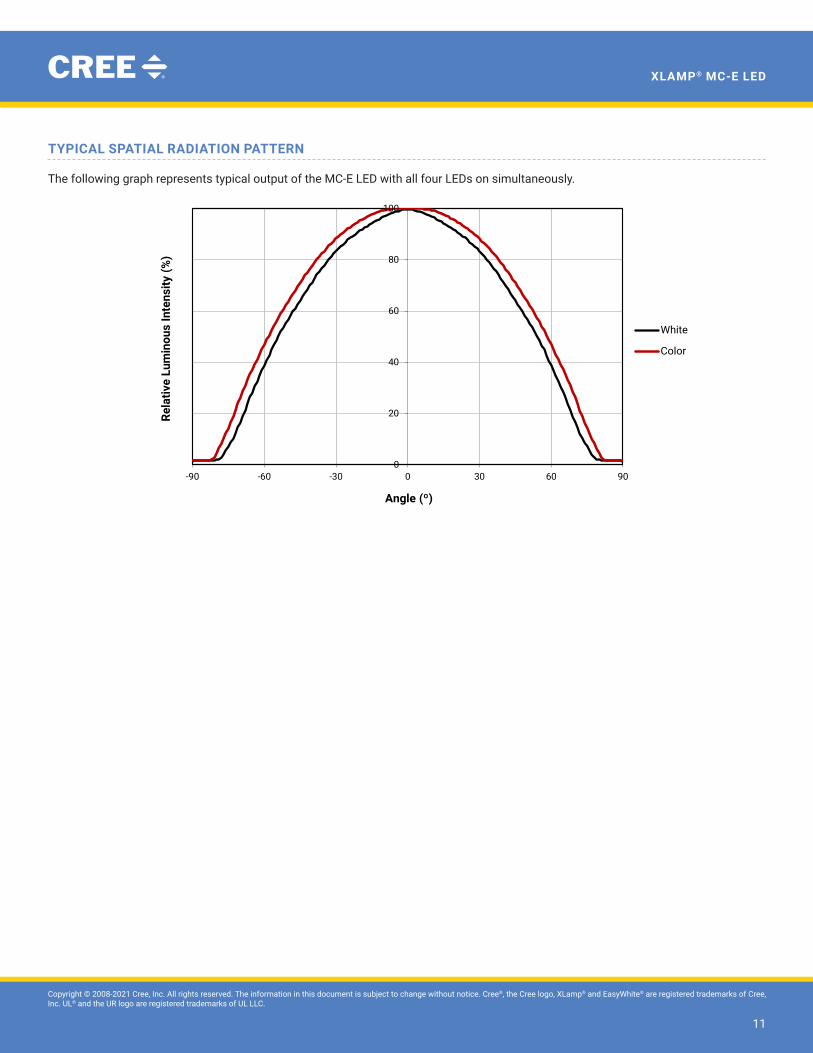
TYPICAL SPATIAL RADIATION PATTERN
The following graph represents typical output of the MC-E LED with all four LEDs on simultaneously.
Typical Spatial Radiation PatternThe following graph represents typical spectral output of the XLamp MC-E LED with all four LEDs on simultaneously.
0
20
40
60
80
100
-90 -60 -30 0 30 60 90
Rela
tive
Lum
inou
s In
tens
ity (%
)
Angle (º)
White
Color

Copyright © 2008-2021 Cree, Inc. All rights reserved. The information in this document is subject to change without notice. Cree®, the Cree logo, XLamp® and EasyWhite® are registered trademarks of Cree, Inc. UL® and the UR logo are registered trademarks of UL LLC.
12
XLAMP® MC-E LED
PERFORMANCE GROUPS – BRIGHTNESS
MC-E white and EasyWhite® LEDs are tested for luminous flux and placed into one of the following luminous-flux groups:
Group Code Minimum Luminous Flux @ 350 mA (lm)
Maximum Luminous Flux @ 350 mA (lm)
F 210 240
G 240 280
H 280 320
J 320 370
K 370 430
M 430 490
• Flux and chromaticity are measured with each LED die connected to independent drive circuits at 350 mA.
• The flux and chromaticity are measured with all LEDs lit simultaneously.
Each LED die in the MC-E color LED is tested individually for luminous flux and placed into one of the following luminous-flux groups. The
luminous-flux groups for the MC-E color LED specify only minimum flux and do not have a maximum.
Color Group Code Minimum Luminous Flux@ 350 mA
Red K 30.6
Green P 67.2
Blue E 8.2
WhiteJ 80
K 100

Copyright © 2008-2021 Cree, Inc. All rights reserved. The information in this document is subject to change without notice. Cree®, the Cree logo, XLamp® and EasyWhite® are registered trademarks of Cree, Inc. UL® and the UR logo are registered trademarks of UL LLC.
13
XLAMP® MC-E LED
PERFORMANCE GROUPS – CHROMATICITY (IF = 350 mA PER EMITTER)
MC-E white LEDs and the white LED in the MC-E color LED are tested for chromaticity and placed into one of the regions defined by
the bounding coordinates on the following pages. The MC-E white and EasyWhite LEDs are tested with each LED die connected to
independent drive circuits at 350 mA and all LED die lit simultaneously. The white LED in the MC-E Color LED is tested individually.
Region x y Region x y
WK
.283 .284
WF
.314 .355
.295 .297 .316 .332
.298 .288 .306 .322
.287 .276 .301 .342
WA
.292 .306
WP
.317 .319
.295 .297 .329 .330
.283 .284 .329 .318
.279 .291 .318 .308
WM
.295 .297
WD
.329 .345
.308 .311 .329 .330
.310 .300 .317 .319
.298 .288 .316 .332
WB
.306 .322
WG
.329 .369
.308 .311 .329 .345
.295 .297 .316 .332
.292 .306 .314 .355
WE
.301 .342
WJ
.329 .330
.306 .322 .329 .345
.292 .306 .346 .359
.287 .321 .344 .342
WN
.308 .311
WH
.348 .384
.317 .319 .346 .359
.318 .308 .329 .345
.310 .300 .329 .369
WC
.316 .332
.317 .319
.308 .311
.306 .322
Copyright © 2008-2021 Cree, Inc. All rights reserved. The information in this document is subject to change without notice. Cree®, the Cree logo, XLamp® and EasyWhite® are registered trademarks of Cree, Inc. UL® and the UR logo are registered trademarks of UL LLC.
14
XLAMP® MC-E LED
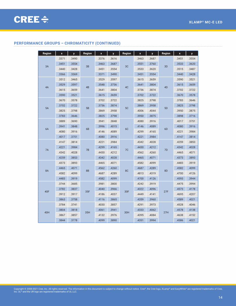
PERFORMANCE GROUPS – CHROMATICITY (CONTINUED)
Region x y Region x y Region x y Region x y
3A
.3371 .3490
3B
.3376 .3616
3C
.3463 .3687
3D
.3451 .3554
.3451 .3554 .3463 .3687 .3551 .3760 .3533 .3620
.3440 .3428 .3451 .3554 .3533 .3620 .3515 .3487
.3366 .3369 .3371 .3490 .3451 .3554 .3440 .3428
4A
.3512 .3465
4B
.3529 .3597
4C
.3615 .3659
4D
.3590 .3521
.3529 .3597 .3548 .3736 .3641 .3804 .3615 .3659
.3615 .3659 .3641 .3804 .3736 .3874 .3702 .3722
.3590 .3521 .3615 .3659 .3702 .3722 .3670 .3578
5A
.3670 .3578
5B
.3702 .3722
5C
.3825 .3798
5D
.3783 .3646
.3702 .3722 .3736 .3874 .3869 .3958 .3825 .3798
.3825 .3798 .3869 .3958 .4006 .4044 .3950 .3875
.3783 .3646 .3825 .3798 .3950 .3875 .3898 .3716
6A
.3889 .3690
6B
.3941 .3848
6C
.4080 .3916
6D
.4017 .3751
.3941 .3848 .3996 .4015 .4146 .4089 .4080 .3916
.4080 .3916 .4146 .4089 .4299 .4165 .4221 .3984
.4017 .3751 .4080 .3916 .4221 .3984 .4147 .3814
7A
.4147 .3814
7B
.4221 .3984
7C
.4342 .4028
7D
.4259 .3853
.4221 .3984 .4299 .4165 .4430 .4212 .4342 .4028
.4342 .4028 .4430 .4212 .4562 .4260 .4465 .4071
.4259 .3853 .4342 .4028 .4465 .4071 .4373 .3893
8A
.4373 .3893
8B
.4465 .4071
8C
.4582 .4099
8D
.4483 .3919
.4465 .4071 .4562 .4260 .4687 .4289 .4582 .4099
.4582 .4099 .4687 .4289 .4813 .4319 .4700 .4126
.4483 .3919 .4582 .4099 .4700 .4126 .4593 .3944
40F
.3744 .3685
35F
.3981 .3800
30F
.4242 .3919
27F
.4475 .3994
.3782 .3837 .4040 .3966 .4322 .4096 .4573 .4178
.3912 .3917 .4186 .4037 .4449 .4141 .4695 .4207
.3863 .3758 .4116 .3865 .4359 .3960 .4589 .4021
40H
.3784 .3741
35H
.4030 .3857
30H
.4291 .3973
27H
.4528 .4046
.3804 .3818 .4061 .3941 .4333 .4062 .4578 .4138
.3867 .3857 .4132 .3976 .4395 .4084 .4638 .4152
.3844 .3778 .4099 .3890 .4351 .3994 .4586 .4021

Copyright © 2008-2021 Cree, Inc. All rights reserved. The information in this document is subject to change without notice. Cree®, the Cree logo, XLamp® and EasyWhite® are registered trademarks of Cree, Inc. UL® and the UR logo are registered trademarks of UL LLC.
15
XLAMP® MC-E LED
PERFORMANCE GROUPS – DOMINANT WAVELENGTH
The red, green and blue LEDs in the MC-E color LED are tested individually for dominant wavelength (DWL) and sorted into one of the DWL
bins defined below.
Color DWL Group Minimum DWL@ 350 mA
Maximum DWL@ 350 mA
Blue
K 450 455
L 455 460
M 460 465
Green
2 520 525
3 525 530
4 530 535
Red A 620 630
CREE’S STANDARD CHROMATICITY REGIONS PLOTTED ON THE 1931 CIE CURVE
Cool White
BBL
5000 K
5700 K
6350 K
7000 K
8300 K
10000 K0.30
0.29
0.28
0.27
0.26
0.31
0.32
0.33
0.34
0.35
0.36
0.37
0.38
0.39
0.40
CCy
CCx
0.27 0.28 0.29 0.30 0.31 0.32 0.33 0.35 0.360.34
WH
WG
WJ
WD
WP
WF
WC
WN
WE
WA
WK
WB
WM

Copyright © 2008-2021 Cree, Inc. All rights reserved. The information in this document is subject to change without notice. Cree®, the Cree logo, XLamp® and EasyWhite® are registered trademarks of Cree, Inc. UL® and the UR logo are registered trademarks of UL LLC.
16
XLAMP® MC-E LED
CREE’S STANDARD CHROMATICITY REGIONS PLOTTED ON THE 1931 CIE CURVE - CONTINUED
Neutral and
Warm White2600 K
2700 K2900 K3000 K
3200 K
3500 K3700 K
4000 K
4300 K
4500 K
4750 K5000 K
5300 K
3A
3B
3C
3D4A
4B
4C
4D
5A
5B
5C
5D6A
6B
6C
6D
7A
7B7C
7D8A
8B8C
8D
0.32
0.33
0.34
0.35
0.36
0.37
0.38
0.39
0.40
0.41
0.42
0.43
0.44
0.45
0.32
0.33
0.34
0.35
0.36
0.37
0.38
0.39
0.40
0.41
0.42
0.43
0.44
0.45
0.46
0.47
0.48
0.49
CCy
CCx
ANSIC78.377A
Copyright © 2008-2021 Cree, Inc. All rights reserved. The information in this document is subject to change without notice. Cree®, the Cree logo, XLamp® and EasyWhite® are registered trademarks of Cree, Inc. UL® and the UR logo are registered trademarks of UL LLC.
17
XLAMP® MC-E LED
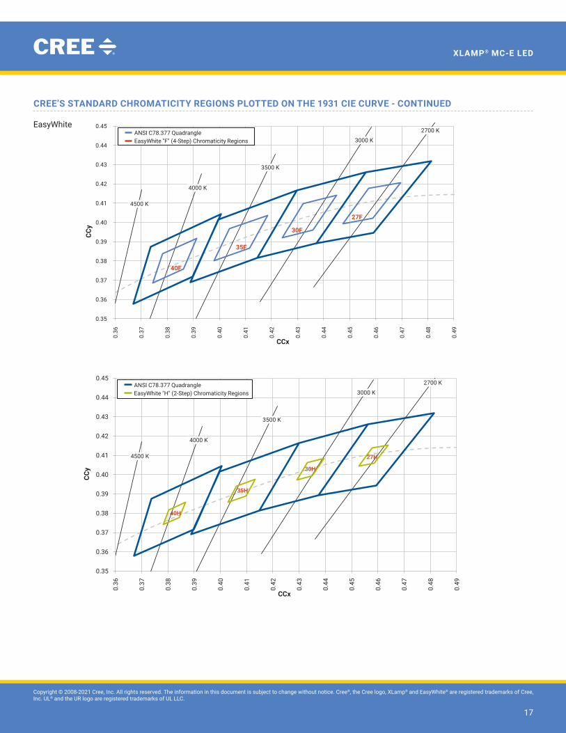
CREE’S STANDARD CHROMATICITY REGIONS PLOTTED ON THE 1931 CIE CURVE - CONTINUED
EasyWhite2700 K
3000 K
3500 K
4000 K
4500 K
40F
35F
30F
27F
0.35
0.36
0.37
0.38
0.39
0.40
0.41
0.42
0.43
0.44
0.45
0.36
0.37
0.38
0.39
0.40
0.41
0.42
0.43
0.44
0.45
0.46
0.47
0.48
0.49
CCy
CCx
ANSI C78.377 QuadrangleEasyWhite "F" (4-Step) Chromaticity Regions
2700 K
3000 K
3500 K
4000 K
4500 K
40H
35H
30H
27H
0.35
0.36
0.37
0.38
0.39
0.40
0.41
0.42
0.43
0.44
0.45
0.36
0.37
0.38
0.39
0.40
0.41
0.42
0.43
0.44
0.45
0.46
0.47
0.48
0.49
CCx
ANSI C78.377 QuadrangleEasyWhite "H" (2-Step) Chromaticity Regions
CCy

Copyright © 2008-2021 Cree, Inc. All rights reserved. The information in this document is subject to change without notice. Cree®, the Cree logo, XLamp® and EasyWhite® are registered trademarks of Cree, Inc. UL® and the UR logo are registered trademarks of UL LLC.
18
XLAMP® MC-E LED
BIN AND ORDER CODE FORMAT (WHITE)
Bin codes and order codes are configured in the following manner:
SSSGCC-BD-HHHH-NNNNNNInternal code
CRI A = Standard CRI
Number of chips 4 = 4 chips
Series MCE = MC-E
Color WT = White
Optical characteristic 2 = Lambertian
Kit number
Order Code
Bin Code
SSSGCC-BD-WWW-FF-G-AAAAAInternal code
Optical characteristic
Number of chips 4 = 4 chips
Series MCE = MC-E
Color WT = White
CRI A = Standard CRI
Chromaticity group
Luminous flux group

Copyright © 2008-2021 Cree, Inc. All rights reserved. The information in this document is subject to change without notice. Cree®, the Cree logo, XLamp® and EasyWhite® are registered trademarks of Cree, Inc. UL® and the UR logo are registered trademarks of UL LLC.
19
XLAMP® MC-E LED
BIN AND ORDER CODE FORMAT (EASYWHITE®)
Bin codes and order codes are configured in the following manner:
SSSCCC-BD-HHHH-NNNNNNNNNKit number
Optical characteristic
Color EZW = EasyWhite
Series MCE = MC-E
CRI A = Standard CRI H = 80 CRI P = 85 CRI U = 90 CRI
Internal codeOrder Code
SSSCCC-BD-WWW-FF-GG-AAAA
Series MCE = MC-E
CRI A = Standard CRI H = 80 CRI P = 85 CRI U = 90 CRI
Chromaticity group
Internal code
Flux group
Optical characteristic
Color EZW = EasyWhite
Bin Code

Copyright © 2008-2021 Cree, Inc. All rights reserved. The information in this document is subject to change without notice. Cree®, the Cree logo, XLamp® and EasyWhite® are registered trademarks of Cree, Inc. UL® and the UR logo are registered trademarks of UL LLC.
20
XLAMP® MC-E LED
BIN AND ORDER CODE FORMAT (COLOR)
Bin codes and order codes are configured in the following manner:
SSSGCC-BD-HHHH-NNNNNNNNN
Series MCE = MC-E
Color CT = Red, green, blue, white
Optical characteristics 2 = Lambertian
Internal code
Dominant wavelength kit (RGB)
Chromaticity kit for white
Flux kit
Internal code
Package configuration A = Individually addressable (all anodes on same side)
Number of chips 4 = 4 chips
Order Code
SSSGCC-BD-HHHH-NNNMMMKKKChromaticity bin for white die
Flux bin for each die (RGBW)
Package configuration A = Individually addressable (all anodes on same side)
Number of chips 4 = 4 chips
Series MCE = MC-E
Color CT = Red, green, blue, white
Optical characteristics 2 = Lambertian
Dominant wavelength bin for each die (RGB)
Internal code
Bin Code

Copyright © 2008-2021 Cree, Inc. All rights reserved. The information in this document is subject to change without notice. Cree®, the Cree logo, XLamp® and EasyWhite® are registered trademarks of Cree, Inc. UL® and the UR logo are registered trademarks of UL LLC.
21
XLAMP® MC-E LED
REFLOW SOLDERING CHARACTERISTICS
In testing, Cree has found MC-E LEDs to be compatible with JEDEC J-STD-020C, using the parameters listed below. As a general guideline,
Cree recommends that users follow the recommended soldering profile provided by the manufacturer of the solder paste used, and
therefore it is the lamp or luminaire manufacturer’s responsibility to determine applicable soldering requirements.
Note that this general guideline may not apply to all PCB designs and configurations of reflow soldering equipment.
Profile Feature Lead-Free Solder
Average Ramp-Up Rate (Tsmax to Tp) 1.2 °C/second
Preheat: Temperature Min (Tsmin) 120 °C
Preheat: Temperature Max (Tsmax) 170 °C
Preheat: Time (tsmin to tsmax) 65-150 seconds
Time Maintained Above: Temperature (TL) 217 °C
Time Maintained Above: Time (tL) 45-90 seconds
Peak/Classification Temperature (Tp) 235 - 245 °C
Time Within 5 °C of Actual Peak Temperature (tp) 20-40 seconds
Ramp-Down Rate 1 - 6 °C/second
Time 25 °C to Peak Temperature 4 minutes max.
Note: All temperatures refer to topside of the package, measured on the package body surface.
TP
TL
Tem
pera
ture
Timet 25˚C to Peak
Preheatts
tS
tP
25
Ramp-down
Ramp-up
Critical ZoneTL to TP
Tsmax
Tsmin

Copyright © 2008-2021 Cree, Inc. All rights reserved. The information in this document is subject to change without notice. Cree®, the Cree logo, XLamp® and EasyWhite® are registered trademarks of Cree, Inc. UL® and the UR logo are registered trademarks of UL LLC.
22
XLAMP® MC-E LED
NOTES
MeasurementsThe luminous flux, radiant power, chromaticity, forward voltage and CRI measurements in this document are binning specifications only
and solely represent product measurements as of the date of shipment. These measurements will change over time based on a number
of factors that are not within Cree’s control and are not intended or provided as operational specifications for the products. Calculated
values are provided for informational purposes only and are not intended or provided as specifications.
Pre-Release Qualification TestingPlease read the LED Reliability Overview for details of the qualification process Cree applies to ensure long-term reliability for LEDs and
details of Cree’s pre-release qualification testing for LEDs.
Lumen MaintenanceCree now uses standardized IES LM-80-08 and TM-21-11 methods for collecting long-term data and extrapolating LED lumen maintenance.
For information on the specific LM-80 data sets available for this LED, refer to the public LM-80 results document.
Moisture SensitivityCree recommends keeping MC-E LEDs in the provided, resealable moisture-barrier packaging (MBP) until immediately prior to soldering.
Unopened MBPs that contain LEDs do not need special storage for moisture sensitivity.
Once the MBP is opened, MC-E LEDs should be handled and stored as MSL 4 per JEDEC J-STD-033, meaning they have limited exposure
time before damage to the LED may occur during the soldering
operation. The table on the right specifies the maximum exposure
time in days depending on temperature and humidity conditions.
LEDs with exposure time longer than the specified maximums
must be baked according to the baking conditions listed below.
Baking ConditionsIt is not necessary to bake all MC-E LEDs. Only the LEDs that meet all of the following criteria must be baked:
• LEDs that have been removed from the original MBP.
• LEDs that have been exposed to a humid environment longer than listed in the Moisture Sensitivity section above.
• LEDs that have not been soldered.
LEDs should be baked at 70 ºC for 24 hours. LEDs may be baked on the original reels. Remove LEDs from the MBP before baking. Do
not bake parts at temperatures higher than 70 ºC. This baking operation resets the exposure time as defined in the Moisture Sensitivity
section above.
TemperatureMaximum Percent Relative Humidity
30% 40% 50% 60% 70% 80% 90%
30 ºC 9 5 4 3 1 1 1
25 ºC 12 7 5 4 2 1 1
20 ºC 17 9 7 6 2 2 1

Copyright © 2008-2021 Cree, Inc. All rights reserved. The information in this document is subject to change without notice. Cree®, the Cree logo, XLamp® and EasyWhite® are registered trademarks of Cree, Inc. UL® and the UR logo are registered trademarks of UL LLC.
23
XLAMP® MC-E LED
Storage ConditionsMC-E LEDs that have been removed from the original MBP but not soldered yet should be stored in a room or cabinet that will maintain
an atmosphere of 25 ± 5 ºC and no greater than 10% RH. For LEDs stored in these conditions, storage time does not add to exposure time
as defined in the above Moisture Sensitivity section.
RoHS ComplianceThe levels of RoHS restricted materials in this product are below the maximum concentration values (also referred to as the threshold
limits) permitted for such substances, or are used in an exempted application, in accordance with EU Directive 2011/65/EC (RoHS2), as
implemented January 2, 2013. RoHS Declarations for this product can be obtained from your Cree representative or from the Product
Ecology section of the Cree website.
REACh ComplianceREACh substances of high concern (SVHCs) information is available for this product. Since the European Chemical Agency (ECHA) has
published notice of their intent to frequently revise the SVHC listing for the foreseeable future, please contact a Cree representative to
insure you get the most up-to-date REACh SVHC Declaration. REACh banned substance information (REACh Article 67) is also available
upon request.
UL® Recognized ComponentThis product meets the requirements to be considered a UL Recognized Component with Level 1 enclosure consideration. The LED
package or a portion thereof has not been investigated as a fire enclosure or a fire and electrical enclosure per ANSI/UL 8750.
Vision AdvisoryWARNING. Do not look at ab exposed lamp in operation. Eye injury can result. For more information about LEDs and eye safety, please
refer to the LED Eye Safety application note.
NOTES - CONTINUED

Copyright © 2008-2021 Cree, Inc. All rights reserved. The information in this document is subject to change without notice. Cree®, the Cree logo, XLamp® and EasyWhite® are registered trademarks of Cree, Inc. UL® and the UR logo are registered trademarks of UL LLC.
24
XLAMP® MC-E LED
MECHANICAL DIMENSIONS
All measurements are ±.1 mm unless otherwise indicated.
Bottom ViewSide View
9.0 .0+.2
.80TYP.
7.50
7.00
.75
.10
1.50 BSCPITCH
1 2 3 4
5678
.05±.05
.25
1.45
R3.18
4.48±.20
A
5.40
2.60
2.84 7.70 10.02
5.60
1.00 TYP.
1.50 BSCPITCH
2.75
1.16
3.85
1.30
2.00
7090MC PARALLEL / INDEPENDENTCONFIGURATION
D8
D7
D6
D5
D4
D3
D2
D1
NEGATIVE (-) 45 4
POSITIVE (+) 4
NEGATIVE (-) 36 3
POSITIVE (+) 3
NEGATIVE (-) 27 2
POSITIVE (+) 2
8 1NEGATIVE (-) 1 POSITIVE (+) 1
HEATSINK
RECOMMENDED PCB SOLDER PADTolerances: .101.Solder mask windows must be .05 mm bigger 2.than PCB Solder Pad.
+.13-.03
D1
D2 D3
D4
REVISIONS
REV COMMENTS DATE APPROVED BY
A Initial Release 10/16/07 RC
B Change height due to new lens 10/23/2007 RC
C Change recommended solder pad footprint 11/26/2007 RC
D Height change due to new lens (was 3.86) 12/26/2007 RC
E - Change package height FROM 1.5 TO 1.45 - Add LED reference designators - Delete Series Configuration schematic - Add tabs to recommended PCB footprint
5/12/2008 RC
SHEET 1 OF 120:1
2610-00005SIZE
TITLE
REV.
CDRAWING NO.
DATE
DATE
DATE
CHECK
FINAL PROTECTIVE FINISH
MATERIAL
APPROVED
DRAWN BY
THIRD ANGLE PROJECTION
.X ± 0.3
X° ± 2°
.XX ± .10
.X ± .25FOR SHEET METAL PARTS ONLY
.XX ± .13
X° ± 1°
UNLESS OTHERWISE SPECIFIEDDIMENSIONS ARE IN
MILLIMETERS & BEFORE FINISH.TOLERANCE UNLESS SPECIFIED:
SCALE
A
B
C
D
123456
6 5 4 3 2 1
A
B
C
D
4600 Silicon DriveDurham, N.C 27703
UNAUTHORIZED PERSON WITHOUT THE WRITTEN CONSENTMAY NOT BE COPIED, REPRODUCED OR DISCLOSED TO ANY CONFIDENTIAL INFORMATION OF CREE, INC. THIS PLOT CONTAINED WITHIN ARE THE PROPRIETARY ANDCREE CONFIDENTIAL. THIS PLOT AND THE INFORMATION
OF CREE INC.
NOTICE
OUTLINE DRAWING, 7090MC PACKAGE
E
R.Chaloupecky 10/16/07
Ban Loh
Top View
9.0 .0+.2
.80TYP.
7.50
7.00
.75
.10
1.50 BSCPITCH
1 2 3 4
5678
.05±.05
.25
1.45
R3.18
4.48±.20
A
5.40
2.60
2.84 7.70 10.02
5.60
1.00 TYP.
1.50 BSCPITCH
2.75
1.16
3.85
1.30
2.00
7090MC PARALLEL / INDEPENDENTCONFIGURATION
D8
D7
D6
D5
D4
D3
D2
D1
NEGATIVE (-) 45 4
POSITIVE (+) 4
NEGATIVE (-) 36 3
POSITIVE (+) 3
NEGATIVE (-) 27 2
POSITIVE (+) 2
8 1NEGATIVE (-) 1 POSITIVE (+) 1
HEATSINK
RECOMMENDED PCB SOLDER PADTolerances: .101.Solder mask windows must be .05 mm bigger 2.than PCB Solder Pad.
+.13-.03
D1
D2 D3
D4
REVISIONS
REV COMMENTS DATE APPROVED BY
A Initial Release 10/16/07 RC
B Change height due to new lens 10/23/2007 RC
C Change recommended solder pad footprint 11/26/2007 RC
D Height change due to new lens (was 3.86) 12/26/2007 RC
E - Change package height FROM 1.5 TO 1.45 - Add LED reference designators - Delete Series Configuration schematic - Add tabs to recommended PCB footprint
5/12/2008 RC
SHEET 1 OF 120:1
2610-00005SIZE
TITLE
REV.
CDRAWING NO.
DATE
DATE
DATE
CHECK
FINAL PROTECTIVE FINISH
MATERIAL
APPROVED
DRAWN BY
THIRD ANGLE PROJECTION
.X ± 0.3
X° ± 2°
.XX ± .10
.X ± .25FOR SHEET METAL PARTS ONLY
.XX ± .13
X° ± 1°
UNLESS OTHERWISE SPECIFIEDDIMENSIONS ARE IN
MILLIMETERS & BEFORE FINISH.TOLERANCE UNLESS SPECIFIED:
SCALE
A
B
C
D
123456
6 5 4 3 2 1
A
B
C
D
4600 Silicon DriveDurham, N.C 27703
UNAUTHORIZED PERSON WITHOUT THE WRITTEN CONSENTMAY NOT BE COPIED, REPRODUCED OR DISCLOSED TO ANY CONFIDENTIAL INFORMATION OF CREE, INC. THIS PLOT CONTAINED WITHIN ARE THE PROPRIETARY ANDCREE CONFIDENTIAL. THIS PLOT AND THE INFORMATION
OF CREE INC.
NOTICE
OUTLINE DRAWING, 7090MC PACKAGE
E
R.Chaloupecky 10/16/07
Ban Loh
ColorD1: RedD2: GreenD3: BlueD4: White
Recommended PCB Solder Pad
9.0 .0+.2
.80TYP.
7.50
7.00
.75
.10
1.50 BSCPITCH
1 2 3 4
5678
.05±.05
.25
1.45
R3.18
4.48±.20
A
5.40
2.60
2.84 7.70 10.02
5.60
1.00 TYP.
1.50 BSCPITCH
2.75
1.16
3.85
1.30
2.00
7090MC PARALLEL / INDEPENDENTCONFIGURATION
D8
D7
D6
D5
D4
D3
D2
D1
NEGATIVE (-) 45 4
POSITIVE (+) 4
NEGATIVE (-) 36 3
POSITIVE (+) 3
NEGATIVE (-) 27 2
POSITIVE (+) 2
8 1NEGATIVE (-) 1 POSITIVE (+) 1
HEATSINK
RECOMMENDED PCB SOLDER PADTolerances: .101.Solder mask windows must be .05 mm bigger 2.than PCB Solder Pad.
+.13-.03
D1
D2 D3
D4
REVISIONS
REV COMMENTS DATE APPROVED BY
A Initial Release 10/16/07 RC
B Change height due to new lens 10/23/2007 RC
C Change recommended solder pad footprint 11/26/2007 RC
D Height change due to new lens (was 3.86) 12/26/2007 RC
E - Change package height FROM 1.5 TO 1.45 - Add LED reference designators - Delete Series Configuration schematic - Add tabs to recommended PCB footprint
5/12/2008 RC
SHEET 1 OF 120:1
2610-00005SIZE
TITLE
REV.
CDRAWING NO.
DATE
DATE
DATE
CHECK
FINAL PROTECTIVE FINISH
MATERIAL
APPROVED
DRAWN BY
THIRD ANGLE PROJECTION
.X ± 0.3
X° ± 2°
.XX ± .10
.X ± .25FOR SHEET METAL PARTS ONLY
.XX ± .13
X° ± 1°
UNLESS OTHERWISE SPECIFIEDDIMENSIONS ARE IN
MILLIMETERS & BEFORE FINISH.TOLERANCE UNLESS SPECIFIED:
SCALE
A
B
C
D
123456
6 5 4 3 2 1
A
B
C
D
4600 Silicon DriveDurham, N.C 27703
UNAUTHORIZED PERSON WITHOUT THE WRITTEN CONSENTMAY NOT BE COPIED, REPRODUCED OR DISCLOSED TO ANY CONFIDENTIAL INFORMATION OF CREE, INC. THIS PLOT CONTAINED WITHIN ARE THE PROPRIETARY ANDCREE CONFIDENTIAL. THIS PLOT AND THE INFORMATION
OF CREE INC.
NOTICE
OUTLINE DRAWING, 7090MC PACKAGE
E
R.Chaloupecky 10/16/07
Ban LohRecommended Stencil Pattern(Shaded Area is Open)
1.24 7.7 10.02
1
1.5
2.75
1.16
3.854

Copyright © 2008-2021 Cree, Inc. All rights reserved. The information in this document is subject to change without notice. Cree®, the Cree logo, XLamp® and EasyWhite® are registered trademarks of Cree, Inc. UL® and the UR logo are registered trademarks of UL LLC.
25
XLAMP® MC-E LED
(200 Lamps)Loaded Pockets
(13 pockets min.)
Trailer160mm (min) ofempty pockets
sealed with tape
(34 empty pockets min.)
Leader400mm (min) of
empty pockets withat least 100mmsealed by tape
STARTEND
Cathode Side
Anode Side(denoted by chamfer)
200.0
A
A
B
5.5±.1
SECTION A-A SCALE 2 : 1
16.0 .0+.3
12.0±.11.75±.10
4.0±.11.5±.1
DETAIL B SCALE 2 : 1
13mm7"
Cover Tape
Pocket Tape
User Feed Direction
User Feed Direction
TAPE AND REEL
All Cree carrier tapes conform to EIA-481D, Automated Component Handling Systems Standard.
Except as noted, all measurements in mm.

Copyright © 2008-2021 Cree, Inc. All rights reserved. The information in this document is subject to change without notice. Cree®, the Cree logo, XLamp® and EasyWhite® are registered trademarks of Cree, Inc. UL® and the UR logo are registered trademarks of UL LLC.
26
XLAMP® MC-E LED
PACKAGING
Patent Label(on bottom of box)
Label with Cree Bin Code, Quantity, Reel ID
Label with Cree Bin Code, Quantity, Reel ID
Label with Cree Order Code, Quantity, Reel ID, PO #
Label with Cree Order Code, Quantity, Reel ID, PO #
Label with Cree Bin Code, Quantity, Reel ID
Unpackaged Reel
Packaged Reel
Boxed Reel
CREE Bin Code& Barcode Label
Vacuum-SealedMoisture Barrier Bag
Label with CustomerP/N, Qty, Lot #, PO #
Label with Cree Bin Code, Qty, Lot #
Label with Cree Bin Code, Qty, Lot #
Vacuum-Sealed Moisture Barrier Bag
Patent Label
Label with Customer Order Code, Qty, Reel ID, PO #
Humidity Indicator Card (inside bag)
Dessicant (inside bag)

Mouser Electronics
Authorized Distributor
Click to View Pricing, Inventory, Delivery & Lifecycle Information: Cree, Inc.:
MCE4WT-A2-0000-000GA9 MCE4WT-A2-0000-000GAA MCE4WT-A2-0000-000GE8 MCE4WT-A2-0000-000GF8
MCE4WT-A2-0000-000HA5 MCE4WT-A2-0000-000HA6 MCE4WT-A2-0000-000HA7 MCE4WT-A2-0000-000HA8
MCE4WT-A2-0000-000HA9 MCE4WT-A2-0000-000HAA MCE4WT-A2-0000-000HE6 MCE4WT-A2-0000-000HE8
MCE4WT-A2-0000-000HF6 MCE4WT-A2-0000-000HF7 MCE4WT-A2-0000-000HF8 MCE4WT-A2-0000-000JA1
MCE4WT-A2-0000-000JA2 MCE4WT-A2-0000-000JA3 MCE4WT-A2-0000-000JA4 MCE4WT-A2-0000-000JA5
MCE4WT-A2-0000-000JA6 MCE4WT-A2-0000-000JA7 MCE4WT-A2-0000-000JA8 MCE4WT-A2-0000-000JA9
MCE4WT-A2-0000-000JAA MCE4WT-A2-0000-000JE3 MCE4WT-A2-0000-000JE6 MCE4WT-A2-0000-000JE7
MCE4WT-A2-0000-000JE8 MCE4WT-A2-0000-000JF4 MCE4WT-A2-0000-000JF5 MCE4WT-A2-0000-000JF6
MCE4WT-A2-0000-000JF7 MCE4WT-A2-0000-000JF8 MCE4WT-A2-0000-000K01 MCE4WT-A2-0000-000K02
MCE4WT-A2-0000-000K03 MCE4WT-A2-0000-000K07 MCE4WT-A2-0000-000K08 MCE4WT-A2-0000-000K09
MCE4WT-A2-0000-000KA1 MCE4WT-A2-0000-000KA2 MCE4WT-A2-0000-000KA3 MCE4WT-A2-0000-000KA4
MCE4WT-A2-0000-000KA5 MCE4WT-A2-0000-000KA6 MCE4WT-A2-0000-000KE3 MCE4WT-A2-0000-000KE4
MCE4WT-A2-0000-000KE5 MCE4WT-A2-0000-000KE6 MCE4WT-A2-0000-000KF4 MCE4WT-A2-0000-000KF5
MCE4WT-A2-0000-000KF6 MCE4WT-A2-0000-000M02 MCE4WT-A2-0000-000M03 MCE4WT-A2-0000-000M07
MCE4WT-A2-0000-000M08 MCE4WT-A2-0000-000M09 MCEEZW-A1-0000-0000G027F MCEEZW-A1-0000-
0000G027H MCEEZW-A1-0000-0000H027F MCEEZW-A1-0000-0000H027H MCEEZW-A1-0000-0000H030F
MCEEZW-A1-0000-0000H030H MCEEZW-A1-0000-0000J027F MCEEZW-A1-0000-0000J027H MCEEZW-A1-0000-
0000J030F MCEEZW-A1-0000-0000J030H MCEEZW-A1-0000-0000J035F MCEEZW-A1-0000-0000J035H
MCEEZW-A1-0000-0000K035F MCEEZW-A1-0000-0000K035H MCE4WT-A2-0000-000JE4 MCE4CT-A2-0000-
00A4AAAB1 MCE4CT-A2-0000-00A5AAAA1 MCE4WT-A2-0000-000HE7 MCE4WT-A2-0000-000JE5 MCE4WT-A2-
0000-000M01 MCEEZW-A1-0000-0000H035F MCEEZW-A1-0000-0000H035H MCEEZW-A1-0000-0000J040F
MCEEZW-A1-0000-0000J040H MCEEZW-A1-0000-0000K040F MCEEZW-A1-0000-0000K040H MCEDWT-A1-0000-
0000A1001 MCEDWT-A1-0000-0000A1002 MCEEZW-H1-0000-0000H035F MCEEZW-H1-0000-0000H035H
MCEEZW-H1-0000-0000H040H MCEEZW-H1-0000-0000J027F MCEEZW-H1-0000-0000J030F MCEEZW-P1-0000-
0000G030F MCEEZW-P1-0000-0000G030H MCEEZW-P1-0000-0000H030F MCEEZW-H1-0000-0000H027F
MCEEZW-P1-0000-0000H030H MCEEZW-P1-0000-0000G027H MCEEZW-H1-0000-0000J040F MCEEZW-H1-0000-
0000H040F MCEEZW-P1-0000-0000H027H