Embed Size (px)
Citation preview

Submittal Cover.doc
ABC ACCREDITED QUALITY CONTRACTOR EC-0000981
430 West Drive Altamonte Springs, Florida 32714 EC-0000981 Phone: (407) 788-3500
CLAY SPRINGS ELEMENTARY SCHOOL
TCE JOB #100707
OWNER: Orange County Public Schools Design & Construction Bldg. 200, 6501 Magic Way Orlando, FL 32809
GENERAL CONTRACTOR: Williams Company 2301 Silver Star Road Orlando, FL 32804
ARCHITECT: Rhodes + Brito Architects 605 E. Robinson Street, Suite 750 Orlando, FL 32801
ENGINEER: Matern Professional Engineering, Inc. 130 Candace Drive Maitland, FL 32751
SUBCONTRACTOR: Tri-City Electrical Contractors, Inc. 430 West Drive Altamonte Springs, FL 32714
Specification Section: 26 05 19 Building Wire & Cable
10/2/14

PRODUCT CATALOG
1 - 8 0 0 - 9 6 2 - 9 4 7 3
1
1410 MILLWOOD ROAD • MCKINNEY, TX. 75069 • 972-542-4744 FAX
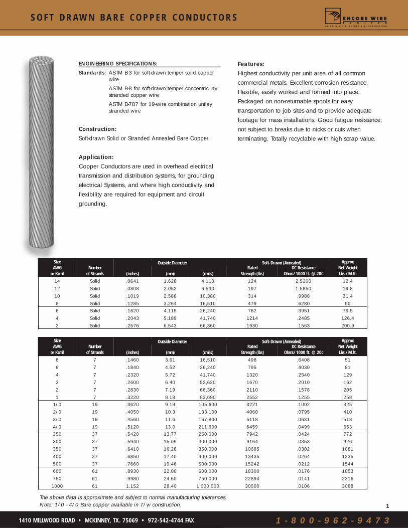
S O F T D R A W N B A R E C O P P E R C O N D U C T O R S
Features:Highest conductivity per unit area of all commoncommercial metals. Excellent corrosion resistance.Flexible, easily worked and formed into place.Packaged on non-returnable spools for easytransportation to job sites and to provide adequatefootage for mass installations. Good fatigue resistance;not subject to breaks due to nicks or cuts whenterminating. Totally recyclable with high scrap value.
ENGINEERING SPECIFICATIONS:
Standards: ASTM B-3 for soft-drawn temper solid copperwire
ASTM B-8 for soft-drawn temper concentric laystranded copper wire
ASTM B-787 for 19-wire combination unilaystranded wire
Construction: Soft-drawn Solid or Stranded Annealed Bare Copper.
Application: Copper Conductors are used in overhead electricaltransmission and distribution systems, for groundingelectrical Systems, and where high conductivity andflexibility are required for equipment and circuitgrounding.
SizeAWG
or KcmilNumber
of Strands (inches) (mm) (cmils)Rated
Strength (lbs)DC Resistance
Ohms/1000 ft. @ 20C
ApproxNet WeightLbs./M.ft.
14 Solid .0641 1.628 4,110 124 2.5200 12.412 Solid .0808 2.052 6,530 197 1.5850 19.810 Solid .1019 2.588 10,380 314 .9988 31.48 Solid .1285 3.264 16,510 479 .6280 506 Solid .1620 4.115 26,240 762 .3951 79.54 Solid .2043 5.189 41,740 1214 .2485 126.42 Solid .2576 6.543 66,360 1930 .1563 200.9
Outside Diameter Soft-Drawn (Annealed)
SizeAWG
or KcmilNumber
of Strands (inches) (mm) (cmils)Rated
Strength (lbs)DC Resistance
Ohms/1000 ft. @ 20c
ApproxNet WeightLbs./M.ft.
8 7 .1460 3.61 16,510 498 .6408 516 7 .1840 4.52 26,240 795 .4030 814 7 .2320 5.72 41,740 1320 .2540 1293 7 .2600 6.40 52,620 1670 .2010 1622 7 .2830 7.19 66,360 2110 .1578 2051 7 .3220 8.18 83,690 2552 .1255 258
1/0 19 .3620 9.19 105,600 3221 .1002 3252/0 19 .4050 10.3 133,100 4060 .0795 4103/0 19 .4560 11.6 167,800 5118 .0631 5184/0 19 .5120 13.0 211,600 6459 .0499 653250 37 .5420 13.77 250,000 7942 .0424 772300 37 .5940 15.09 300,000 9164 .0353 926350 37 .6410 16.28 350,000 10685 .0302 1081400 37 .6850 17.40 400,000 13435 .0264 1235500 37 .7660 19.46 500,000 15242 .0212 1544600 61 .8930 22.00 600,000 18300 .0176 1853750 61 .9980 24.60 750,000 22894 .0141 23161000 61 1.152 28.40 1,000,000 30500 .0106 3088
Outside Diameter Soft-Drawn (Annealed)
The above data is approximate and subject to normal manufacturing tolerances.Note: 1/0 - 4/0 Bare copper available in 7/w construction.

1 - 8 0 0 - 9 6 2 - 9 4 7 3
4
1410 MILLWOOD ROAD • MCKINNEY, TX. 75069 • 972-542-4744 FAX
CopperConductor
PVCInsulation
NylonJacket
T H H N / M T W / T H W N - 2 C O P P E R C O N D U C T O R
Appl i cat ion:Encore Type THHN-THWN-2 building wire is intended forgeneral purpose applications as defined by the NationalElectrical Code (NEC). Suitable for new construction or rewiringfor 600-volt applications. When used as type THHN or THWN-2, conductor is suitable for use in wet or dry locations at temp-eratures not to exceed 90°C, or not to exceed 75°C in oil orcoolants. When used as type MTW, conductor is suitable for usein dry locations at 90°C, or not to exceed 60°C in wet locationsor where exposed to oils or coolants. When used as type AWMtemperatures should not exceed 105°C in dry locations.
LISTED SOLID E-123774STRANDED E-156879
ENGINEERING SPECIFICATIONS:
Standards: Underwriters Laboratories Standard UL-83, UL-1063, UL-758.AWM Spec 1316, 1317, 1318, 1319, 1320, 1321 ASTM StrandingClass B-3, B-8, B-787Federal Specification A-A-59544Canadian Standards Association C22.2 No. 75NEMA WC5/ICEA S-61-402
Packaging: 14 and 12 AWG — 4 x 500' spools, 2,000' per carton or2,500' reels. 10 AWG — 2 x 500' spools, 1,000' percarton or 2,500' reel. 8 AWG — 500' carton, 1,000’,2,500’, or 5,000' reel. 6 AWG — 500', 1,000', 2,500',or 5,000' reel. 4 AWG through 1000 KCMIL — 500',1,000', or longer lengths on reels.
Construction: Conductors: Solid conductors, uncoated copper, perASTM B3. Stranded conductors uncoated copper perASTM B3, ASTM B787and ASTM B8.Conductors Insulation:Color-coded, Polyvinyl chloride (PVC), heat-and Moisture-resistant, flame-retardantcompound per UL-83 and UL-1063.Jacket: A tough, polyamide, outer-nylon coveringper UL-83 and UL-1063.Features: Slick, outer-nylon jacket for easy pulling.VW-1 rated 14 AWG - 1 AWG, 1/0AWG and larger is rated for CT use. 6AWG and larger is rated for SunlightResistance in all colors. All sizes are rated“Gasoline and Oil Resistant II.”Print Legend: Conductor Sizes 14 AWG through 10 AWG Solid:E123774 (SIZE) AWG TYPE THHN ORTHWN-2 GASOLINE AND OIL RESISTANTII VW-1 600V (UL) OR AWM OR C-(UL)TYPE T90 NYLON OR TWN 75 FT1Conductor Sizes 14 AWG through 1 AWG Stranded:E156879 (SIZE) AWG TYPE MTW ORTHHN OR THWN-2 GASOLINE AND OILRESISTANT II VW-1 600V (UL) OR AWMOR C-(UL) TYPE T90 NYLON OR TWN 75FT1 DATE/TIME/OPERConductor Sizes 1/0 AWG - 500 KCMIL Stranded:E156879 (SIZE) AWG OR KCMIL TYPEMTW OR THHN OR THWN-2 GASOLINEAND OIL RESISTANT II SUNLIGHTRESISTANT FOR CT USE 600V (UL) OR C-(UL) TYPE T90 NYLON OR TWN 75 FT1DATE/TIME/OPERConductor Sizes 500 KCMIL - 1000 KCMIL Stranded:E156879 (SIZE) KCMIL TYPE MTW ORTHHN OR THWN-2 GASOLINE AND OILRESISTANT II SUNLIGHT RESISTANT FORCT USE 600V (UL)DATE/TIME/OPER
Ampacity shown above is per the 2002 National Electrical Code. The above data is approximate and subject to normal manufacturing tolerances.
SizeAWG
or Kcmil Number
of Strands
Conductor Size
(mm2)
InsulationThickness
PVC Nylon (Inches) ((mm) 60C 75C 90C
ApproxNet WeightLbs./M.ft.
14 SOL 2.08 .015 .004 .101 2.57 15 15 15 15
12 SOL 3.31 .015 .004 .120 3.05 20 20 20 23
10 SOL 5.26 .020 .004 .149 3.78 30 30 30 3714 19 2.08 .015 .004 .109 2.77 15 15 15 17
12 19 3.31 .015 .004 .127 3.23 20 20 20 24
10 19 5.26 .020 .004 .160 4.07 30 30 30 388 19 8.37 .030 .005 .212 5.39 40 50 55 63
6 19 13.3 .030 .005 .248 6.30 55 65 75 95
4 19 21.2 .040 .006 .317 8.06 70 85 95 153
3 19 26.7 .040 .006 .344 8.74 85 100 110 189
2 19 33.6 .040 .006 .375 9.53 95 115 130 234
1 19 42.4 .050 .007 .435 11.05 110 130 150 2991/0 19 53.5 .050 .007 .474 12.04 125 150 170 372
2/0 19 67.4 .050 .007 .518 13.16 145 175 195 462
3/0 19 85.0 .050 .007 .568 14.43 165 200 225 572
4/0 19 107 .050 .007 .624 15.85 195 230 260 712250 37 127 .060 .008 .678 17.23 215 255 290 851
300 37 152 .060 .008 .730 18.55 240 285 320 1010
350 37 177 .060 .008 .777 19.74 260 310 350 1170
400 37 203 .060 .008 .821 20.86 280 335 380 1330
500 37 253 .060 .008 .902 22.91 320 380 430 1650600 61 304 .070 .009 1.051 26.70 355 420 475 1985
750 61 380 .070 .009 1.156 29.37 400 475 535 2455
1000 61 507 .070 .009 1.310 33.28 455 545 615 3252
Overall OutsideDiameter
AllowableAmpacities

grounded in service wired to innovate™
STABILOY®
Type XHHW-2 and USE-2/RHH/RHW-2

Alcan manufactures XHHW-2 and USE-2/RHH/RHW–2 STABILOY®
cables which are intended for use in general purpose wiring in residential,
commercial and industrial construction. In addition, Type
USE-2/RHH/RHW–2 is primarily used as Type USE-2 direct- buried
underground service entrance, but is listed for RHH or RHW-2 for appli-
cations in general purpose lighting and power. As with all STABILOY®
building wire, these products are high quality, dependable and offer
tremendous flexibility. They exceed the requirements of the Underwriters
Laboratories, Inc. standards and are approved for use in accordance with
the recommendations of the National Electrical Code. STABILOY® alloy
conductor is recognized by ASTM.
Product Features Alcan Type XHHW-2 and USE-2/RHH/RHW–2 offer severalexceptional features:
• Lightweight for easier lifting and handling because STABILOYconductors weigh half as much as copper.
• Maximum operating temperature of 90˚C in dry and wet locations which exceeds the requirements for installations ofservice and feeder circuits.
• Sunlight resistant, moisture resistant and flame-retardantinsulation, which enhances the life of the cable by fending offenvironmental elements that can cause deterioration.
• Increased flexibility because both XHHW-2 and USE-2/RHH/RHW-2 are made with STABILOY AA-8030 conductors which require less bending force and have less spring back than copper conductors.
• Cross-linked polyethylene insulation (XLPE) over STABILOYconductors offers higher short-circuit withstand capability thanthe traditional THHN/THWN-2 insulation used on copper conductors.
• NEW! Size 900 kcmil now available as a better choice over 600kcmil copper!
Type XHHW-2 and Type USE-2/RHH/RHW-2

Description:XHHW-2 is a compact stranded conductor. Mylar tape may be placed between the XLPE insulation and the conductor strands.
Application:Installed in raceways for general-purpose wiring for upto 600V rated service and feeder circuits in residential,commercial, institutional and industrial buildings. Also,used in cable trays (with “CT USE” marking) and mes-senger supported wiring applications.
Marking:Cables will bear the following surface marking: Alcan(Plant of Manufacture) (Size) Compact AL STABILOY®AA-8030 Series XLPE 600 V XHHW-2 SUN-RES (UL)(Year of Manufacture).
Available Options:Contact Alcan Cable for:600V XHHW-2 conductors rated for"CT USE" and other markings.
Type XHHW-2
NOTES:1. Data are approximate and subject to normal manufacturing tolerances.2. Standard lengths are subject to normal manufacturing tolerances of ±10%.3. Two, three or four conductors can be paralleled on a reel.4. The suffix -2 indicates that these wire types can be used at a continuous 90°C operating temperature in wet and dry locations.
NOMINAL DIMENSIONSSize Insulation BARE XHHW-2 Bare XHHW-2 NOMINAL WEIGHTAWG Thickness Conductor Conductor Conductor Conductor (LBS./1000FT.) STANDARD PACKAGE
or kcmil (Mils) Diameter Diameter Area Area STABILOY Total Length Reel(Inches) (Inches) (Sq. Inches) (Sq. Inches)
6 45 .169 .260 .0224 .0530 25 39 1000' NRC 16.154 45 .213 .305 .0356 .0730 39 57 1000' NRC 16.152 45 .268 .360 .0564 .1017 62 84 1000' NRC 21.15
1 55 .299 .415 .0702 .1352 79 108 1000' NRC 21.151/0 55 .336 .450 .0887 .1590 99 132 1000' NRC 21.152/0 55 .376 .490 .1110 .1885 125 161 1000' NRC 21.183/0 55 .423 .540 .1405 .2290 157 198 1000' NRC 24.154/0 55 .475 .590 .1772 .2733 199 244 1000' NRC 24.18
250 65 .520 .655 .2124 .3370 235 292 1000' NRC 27.18300 65 .570 .705 .2552 .3904 282 344 1000' NRC 30.18350 65 .616 .750 .2980 .4418 329 396 1000' NRC 30.24400 65 .659 .795 .3411 .4964 376 448 1000' NRC 32.24500 65 .736 .870 .4254 .5945 469 550 1000' NRC 32.24
600 80 .813 .980 .5191 .7542 563 671 1000' NRC 36.24700 80 .877 1.040 .6041 .8494 657 774 1000' NRC 40.24750 80 .908 1.075 .6475 .9076 704 824 1000' NRC 40.24900 80 .999 1.169 .7838 1.0733 847 983 1000' NRC 42.261000 80 1.060 1.230 .8825 1.1882 939 1079 1000' NRC 48.25

Allowable Ampacities†
30°C (86°F) Ambient Temperature
Ampacities are based on conductor operating tempera-tures only and do not take voltage drop into consideration.
When the number of current carrying conductors in a raceway or cable exceeds three, the allowable ampacity of each conductor shall be reduced to the following percentages of tabular values:
4 to 6 80%7 to 9 70%10 to 20 50%21 to 30 45%31 to 40 40%
In dwelling units, conductors are permitted to be utilized as 120/240 volt, 3-wire, single-phase serviceentrance conductors and feeder conductors in raceway or cable with or without an equipment grounding con-ductor. The allowable ampacity for Types XHHW-2, RHW-2and RHH aluminum conductors are:
S T A B I L O Y X H H W-2 v s . C o p p e r T H W N & T H H NA m p a c i t i e s a n d C o r r e c t i o n F a c t o r s
NOTES:1.Based on NEC Table 310.16.
† See termination provisions for conductor sizing as given in Underwriters Laboratories Electrical Construction MaterialsDirectory, “Equipment for Use in Ordinary Locations.”
STABILOY Type XHHW-2 and Type USE-2/RHH/RHW-2 con-ductors can be operated at 90°C in dry AND wet locations.This characteristic is advantageous when derating of con-ductor ampacity is required, for example, when there arefour or more current carrying conductors in a raceway orcable in a wet location. In this instance one can begin withthe 90°C ampacity from which to derate.
System design loads falling between values listed in thistable for copper THHN often permit the use of a smallerSTABILOY conductor than would be necessary based onthe maximum ampacity of the copper conductor required.
Example:For a design load of 380 amps, the required 500 kcmil copper THHN conductor would have to be replaced by a 750 kcmil STABILOY conductor (75°C, wet location).However, if the design load was between 336 and 375 amps(still requiring 500 kcmil copper), a 700 kcmil STABILOY conductor would be adequate.
AMPACITIES (AMPS)†
Conductor Size COPPER STABILOY Conductor SizeAWG or kcmil THWN (75°C) THHN, THHN-2 (90°C) XHHW (75°C) XHHW-2 (90°C) AWG or kcmil
6 65 75 50 60 64 85 95 65 75 42 115 130 90 100 21 130 150 100 115 1
1/0 150 170 120 135 1/02/0 175 195 135 150 2/03/0 200 225 155 175 3/04/0 230 260 180 205 4/0250 255 290 205 230 250300 285 320 230 255 300350 310 350 250 280 350400 335 380 270 305 400500 380 430 310 350 500600 420 475 340 385 600700 460 520 375 420 700750 475 535 385 435 750900 520 585 425 480 9001000 545 615 445 500 1000
Size Amps#2AWG 1001 1101/0 1252/0 150
Size Amps350kcmil 300500kcmil 350600 kcmil 400
Size Amps3/0 1754/0 200250kcmil 225300kcmil 250

S T A B I L O Y A m p a c i t i e s a n d C o r r e c t i o n F a c t o r s
NOT MORE THAN THREE* SINGLE INSULATED CONDUCTORS IN A RACEWAY IN FREE AIR** SINGLE INSULATED CONDUCTOR IN FREE AIR**
75°C (167°F) 90°C (194°F) 75°C (167°F) 90°C (194°F)Size AWG XHHW, XHHW-2, RHH, XHHW, XHHW-2, RHH, Size AWGor kcmil RHH, RHW, USE RHW-2, USE-2 RHH, RHW, USE RHW-2, USE-2 or kcmil
8 40 45 55 60 86 50 60 75 80 64 65 75 100 110 42† 90 100 135 150 2†
1† 100 115 155 175 1†
1/0† 120 135 180 205 1/0†
2/0† 135 150 210 235 2/0†
3/0† 155 175 240 275 3/0†
4/0† 180 205 280 315 4/0†
250 205 230 315 355 250300 230 255 350 395 300350 250 280 395 445 350400 270 305 425 480 400500 310 350 485 545 500600 340 385 540 615 600700 375 420 595 675 700750 385 435 620 700 750900 425 480 700 785 9001000 445 500 750 845 1000
NOTES:
1. Ampacities are based on conductor operating temperatures only and do not take voltage drop into consideration.
2. A neutral conductor which carries only the unbalanced current from other conductors, as in the case of normally balanced cir-cuits of three or more conductors, shall not be counted in determining Ampacity Adjustment Factors. But in a three-wire circuitconsisting of two phase wires and the neutral of a four-wire three-phase Wye-connected system, a common conductor carriesapproximately the same current as the other conductors and shall be counted in determining ampacities.
3. Based on Ambient Air Temperature of 30°C (86°F).
* See 310.15(B)(4)
** See termination provisions for conductor sizing as given in Underwriters Laboratories Electrical Construction MaterialsDirectory, “Equipment for Use in Ordinary Locations.”
† In dwelling units, conductors shall be permitted to be utilized as 120/240 volt, 3-wire, single-phase service entrance conductorsand feeder conductors in raceway or cable with or without an equipment grounding conductor. The allowable ampacity for TypesXHHW-2, RHW-2 and RHH aluminum conductors shall be:
Ampacity Correction Factors
For ambient temperatures other than 30°C (86°F), multiply the
ampacities shown above by the
Ambientappropriate factor shown below.
AmbientTemp.°C 75°C 90°C Temp.°F
21–25 1.05 1.04 70–7726–30 1.00 1.00 79–8631–35 .94 .96 88–9536–40 .88 .91 97–10441–45 .82 .87 106–11346–50 .75 .82 115–12251–55 .67 .76 124–13156–60 .58 .71 133–14061–70 .33 .58 142–15871–80 – .41 160–176
Size Amps#2AWG 1001 1101/0 1252/0 150
Size Amps350kcmil 300500kcmil 350600 kcmil 400
Size Amps3/0 1754/0 200250kcmil 225300kcmil 250

MAX
IMUM
NUM
BER
OF T
YPE
XHHW
-2 C
OMPA
CT S
TABI
LOYR
ALUM
INUM
ALL
OY C
ONDU
CTOR
S IN
CON
DUIT
TABL
E C7
ATA
BLE
C9A
TABL
E C1
1ACO
NDUC
TOR
LIQU
IDTI
GHT
FLEX
IBLE
MET
ALLI
C CO
NDUI
TRI
GID
PVC
COND
UIT,
Sch
edul
e 80
Type
A R
IGID
PVC
CON
DUIT
SIZE
TRAD
E SI
ZES
IN IN
CHES
TRAD
E SI
ZES
IN IN
CHES
TRAD
E SI
ZES
IN IN
CHES
AWG/
KCM
IL3/
81/
23/
41
1 1/
41
1/2
22
1/2
33
1/2
41/
23/
41
1 1/
41
1/2
22
1/2
33
1/2
45
61/
23/
41
1 1/
41
1/2
22
1/2
33
1/2
46
12
46
1115
2437
5673
951
35
913
2131
4865
8513
419
33
58
1317
2741
6280
103
41
13
48
1117
2641
5369
11
36
915
2235
4761
9814
01
36
912
2030
4558
752
11
13
67
1219
2938
501
12
56
1116
2534
4470
100
12
47
914
2132
4254
10
11
24
69
1422
2837
11
13
58
1219
2533
5375
11
35
710
1624
3140
1/0
01
11
45
812
1924
320
11
34
710
1622
2845
641
12
46
913
2027
342/
00
11
13
47
1016
2027
01
12
36
813
1824
3854
11
13
57
1117
2229
3/0
00
11
23
58
1317
220
11
13
57
1115
1931
441
11
34
69
1418
244/
00
01
11
34
711
1418
00
11
24
69
1216
2637
01
12
35
812
1520
250
00
11
11
35
811
150
01
11
35
710
1321
300
11
12
46
912
1630
00
00
11
13
57
912
00
11
13
46
811
1725
01
11
13
58
1013
350
00
01
11
34
68
110
01
11
23
57
1015
220
01
11
35
79
1240
00
00
11
12
46
710
00
01
11
35
79
1420
00
11
13
46
811
500
00
00
11
13
56
80
00
11
12
45
711
170
01
11
23
57
960
00
00
01
11
24
56
00
01
11
13
46
913
00
01
11
34
57
700
00
00
11
11
34
60
00
01
11
34
58
120
00
11
12
35
675
00
00
01
11
13
45
00
00
11
12
35
711
00
01
11
23
46
900
00
00
01
12
23
40
00
01
11
23
46
80
00
11
12
34
510
000
00
00
11
12
34
00
00
01
11
33
68
00
00
11
12
34
TABL
E C8
ATA
BLE
C10A
TABL
E C1
2ACO
NDUC
TOR
RIGI
D M
ETAL
LIC
COND
UIT
RIGI
D PV
C CO
NDUI
T, S
ched
ule
40
Type
EB,
PVC
CON
DUIT
SI
ZETR
ADE
SIZE
S IN
INCH
ESTR
ADE
SIZE
S IN
INCH
ESTR
ADE
SIZE
S IN
INCH
ESAW
G/KC
MIL
1/2
3/4
11
1/4
1 1/
22
2 1/
23
3 1/
24
56
1/2
3/4
11
1/4
1 1/
22
2 1/
23
3 1/
24
56
23
3 1/
24
56
62
46
1115
2536
5675
9715
222
01
46
1115
2535
5573
9414
921
529
6585
109
167
238
41
35
811
1826
4155
7011
015
91
24
811
1825
4053
6810
815
621
4762
7912
117
22
11
36
813
1929
3950
7911
41
13
58
1318
2838
4977
112
1534
4457
8712
41
11
24
610
1422
2938
6086
11
24
69
1421
2937
5884
1125
3342
6593
1/0
11
14
58
1219
2532
5173
11
13
58
1218
2431
4972
922
2836
5679
2/0
11
13
47
1016
2127
4362
11
13
47
1015
2026
4260
818
2430
4767
3/0
01
12
36
813
1722
3551
01
12
35
812
1722
3450
615
2025
3855
4/0
01
11
35
711
1419
2942
01
11
35
710
1418
2942
512
1621
3246
250
01
11
24
58
1115
2334
00
11
14
58
1114
2333
410
1317
2637
300
00
11
13
57
1013
2029
00
11
13
47
912
1928
48
1114
2231
350
00
11
13
46
911
1825
00
11
13
46
811
1725
37
1012
1928
400
00
11
12
46
810
1623
00
11
12
35
710
1522
37
911
1725
500
00
01
11
35
68
1319
00
01
11
34
68
1318
25
79
1420
600
00
01
11
24
57
1015
00
01
11
24
56
1015
14
67
1116
700
00
01
11
13
46
913
00
01
11
13
45
913
14
56
1014
750
00
01
11
13
45
812
00
01
11
13
45
812
13
56
913
900
00
00
11
22
35
710
00
00
11
12
34
69
13
45
710
1000
00
00
11
12
34
710
00
00
11
12
34
69
13
45
710
DAT
A F
RO
M T
HE
NAT
ION
AL
ELE
CT
RIC
AL
CO
DE
®
ALC
AN
CA
BLE
NE
C is
a r
egis
tere
d tr
adem
ark
of T
he N
atio
nal
Fire
Pro
tect
ion
Ass
ocia
tion
STA
BIL
OY
® is
a r
egis
tere
d tr
adem
ark
of
Alc
an P
rodu
cts
Cor
pora
tion
for
AA
-803
0 A
lum
inum
Allo
y C
ondu
ctor
Mat
eria
l

ALC
AN
CA
BLE
MAX
IMUM
NUM
BER
OF T
YPE
XHHW
-2 C
OMPA
CT S
TABI
LOYR
ALUM
INUM
ALL
OY C
ONDU
CTOR
S IN
CON
DUIT
TABL
E C1
ATA
BLE
C3A
TABL
E C5
ACO
NDUC
TOR
ELEC
TRIC
AL M
ETAL
LIC
TUBI
NGFL
EXIB
LE M
ETAL
LIC
COND
UIT
LIQU
IDTI
GHT
FLEX
IBLE
NON
MET
ALLI
C CO
NDUI
T (F
NMC-
B)
SIZE
TRAD
E SI
ZES
IN IN
CHES
TRAD
E SI
ZES
IN IN
CHES
TRAD
E SI
ZES
IN IN
CHES
AWG/
KCM
IL1/
23/
41
1 1/
41
1/2
22
1/2
33
1/2
41/
23/
41
1 1/
41
1/2
22
1/2
33
1/2
43/
81/
23/
41
1 1/
41
1/2
26
14
611
1525
4466
8711
12
46
914
2437
5372
951
24
611
1524
41
34
811
1832
4863
811
34
710
1827
3852
691
13
48
1117
21
13
68
1323
3445
581
13
57
1319
2838
491
11
36
712
11
12
46
1017
2634
431
12
35
914
2128
370
11
24
69
1/0
11
13
58
1422
2937
11
13
48
1217
2431
01
11
45
82/
01
11
34
712
1824
311
11
24
710
1520
260
11
13
47
3/0
01
12
36
1015
2025
01
11
35
812
1722
00
11
23
54/
00
11
13
58
1317
210
11
12
47
1014
180
01
11
34
250
01
11
24
710
1317
01
11
14
58
1114
00
11
11
330
00
01
11
36
911
140
01
11
35
79
120
00
11
13
350
00
11
13
58
1013
00
11
13
46
811
00
01
11
340
00
01
11
24
79
110
01
11
24
57
100
00
11
12
500
00
01
11
46
79
00
01
11
34
68
00
00
11
160
00
00
11
13
46
80
00
11
12
35
60
00
01
11
700
00
01
11
24
57
00
00
11
13
46
00
00
11
175
00
00
11
12
35
60
00
01
11
34
50
00
01
11
900
00
00
11
23
45
00
00
11
22
34
00
00
01
110
000
00
01
11
34
50
00
01
11
23
40
00
00
11
TABL
E C2
ATA
BLE
C4A
TABL
E C6
ACO
NDUC
TOR
ELEC
TRIC
AL N
ONM
ETAL
LIC
TUBI
NGIN
TERM
EDIA
TE M
ETAL
LIC
COND
UIT
LIQU
IDTI
GHT
FLEX
IBLE
NON
MET
ALLI
C CO
NDUI
T (F
NMC-
A)
SIZE
TRAD
E SI
ZES
IN IN
CHES
TRAD
E SI
ZES
IN IN
CHES
TRAD
E SI
ZES
IN IN
CHES
AWG/
KCM
IL1/
23/
41
1 1/
41
1/2
21/
23/
41
1 1/
41
1/2
22
1/2
33
1/2
43/
81/
23/
41
1 1/
41
1/2
26
13
610
1424
24
712
1627
3859
8010
31
24
611
1525
41
24
710
171
35
912
2028
4358
741
13
48
1118
21
13
57
121
13
68
1420
3141
531
11
36
813
11
12
45
91
13
56
1015
2331
400
11
24
610
1/0
11
13
58
11
14
59
1320
2634
01
11
35
82/
00
11
34
71
11
34
711
1722
290
11
13
47
3/0
01
12
35
01
13
46
914
1824
00
11
23
64/
00
11
13
40
11
23
57
1115
200
01
11
35
250
00
11
13
01
11
24
69
1216
00
11
12
430
00
01
11
30
01
11
35
810
130
00
11
13
350
00
11
13
00
11
13
47
912
00
01
11
340
00
01
11
20
01
11
34
68
110
00
11
12
500
00
01
11
00
01
12
35
79
00
00
11
160
00
00
11
10
00
11
12
45
70
00
01
11
700
00
01
11
00
01
11
23
56
00
00
11
175
00
00
11
10
00
11
11
34
60
00
01
11
900
00
00
11
00
00
11
23
45
00
00
01
110
000
00
01
10
00
01
11
23
40
00
00
11
DAT
A F
RO
M T
HE
NAT
ION
AL
ELE
CT
RIC
AL
CO
DE
®
NE
C is
a r
egis
tere
d tr
adem
ark
of T
he N
atio
nal F
irePr
otec
tion
Ass
ocia
tion
STA
BIL
OY
® is
a r
egis
tere
d tr
adem
ark
of
Alc
an P
rodu
cts
Cor
pora
tion
for
AA
-803
0 A
lum
inum
Allo
y C
ondu
ctor
Mat
eria
l

Wing-Nut® Wire Connectors
� Three color-coded models cover a full range of wire sizes from 18 through 6 AWG
� Specially designed contoured wings provide a secure grip for extra leverage on maximum wire combinations
� Live-action spring expands to accept wire shape and size with no pre-twisting required
� Square-wire spring threads directly onto conductors for fast, secure connections
� Deep skirt helps protect against flash-over and turned-backstrands for maximum dielectric protection
� Easily removed for repeat usage on same size or larger wirecombinations
� Tough, UL 94V-2 flame-retardant shell rated at 105°C (221°F)
� UL Listed to 486C and CSA Certified to C22.2 #188; complywith Federal Specification W-S-610E
� Classified in accordance with IEC Publications 998-2 and 998-2-4
Tough, durablethermoplastic shell
Live-action,square-wire spring
Deep skirt, wide throat
Comfortablecontoured wings
Wire
Co
nn
ecto
rs
www.idealindustries.com 1-800-435-0705 for Customer ServiceA-4
ULRLIST
ED
- WIRE CON
N
C USEN 60-998-2-4
Wire Combination Wire CombinationModel Color Range Range (mm) Quantity Cat. No.
Box of 100 30-451600V* 600V* Jar of 225 30-451J
451® Yellow 18 thru 10 AWG ,75mm2 to 6,0mm2 Jar of 500 30-651JMin. 2 #18 Min. 2-,75mm2 Carton of 1,000 30-551Max. 3 #12 Max. 3-4,0mm2 Keg of 5,000 (10 bags, 500 ea.) 30-651
Barrel of 35,000 30-851Box of 100 30-452
600V* 600V* Jar of 300 30-452J
452® Red 18 thru 8 AWG ,75mm2 to 10,0mm2 Jar of 500 30-652JMin. 2 #18 Min. 2-,75mm2 Carton of 1,000 30-552Max. 4 #10 Max. 4-6,0mm2 Keg of 5,000 (10 bags, 500 ea.) 30-652
Barrel of 25,000 30-852600V* 600V*
454® Blue 14 thru 6 AWG 2,5mm2 to 16,0mm2 Box of 50 30-454
Min. 3 #12 Min. 3-4,0mm2
Keg of 2,500 (25 bags, 100 ea.) 30-654Max. 1 #6 & 2 #8 Max. 2-16,0mm2 w/1-4,0mm2
*1,000V maximum in fixtures and signs
Model A B C D E
451® 15/64 11/32 11/16 5/16 1-1/646 9 18 8 26
452® 21/64 15/32 15/16 5/16 1-15/648.5 12 24 8 31.5
454® 7/16 5/8 1-3/16 13/32 1-15/3211 16 30 10.5 37.5
92® 21/64 13/32 29/32 9/32 1-5/328.5 10.5 23 10 30
Dimensions Inchesmm( )
Min2 #18
Min2 #18
Min3 #12
Max 3 #12
Max 4 #10 Max
1 #6 & 2 #8
451 Yellow
452 Red
454 Blue
Wire Combinations
Model
2 #18 2 #14 3 #12 5 #12 4 #10 5 #10

Wire
Co
nn
ecto
rs
www.idealindustries.com 1-800-435-0705 for Customer ServiceA-2
Wire-Nut® Wire Connectors
Wire Combination Wire CombinationModel Color Range Range (mm) Quantity Cat. No.
300V 300V Box of 100 30-071
71B® Gray 22 to 16 AWG ,34mm2 to 1,5mm2 Carton of 1,000 30-171
Min. 2 #22 – Max. 2 #16 Min. 2-,34mm2 Max. 3-1,5mm2 Keg of 25,000 (loose pack) 30-271Barrel of 150,000 30-871
300V 300VBox of 100 30-072
72B® Blue 22 to 14 AWG ,34mm2 to 2,5mm2 Carton of 1,000 30-172
Min. 2 #22 – Max. 3 #16 Min. 2-,34mm2 Max. 3-1,5mm2 Keg of 10,000 (loose pack) 30-272Barrel of 85,000 30-872
Box of 100 30-073600V* 600V* Jar of 300 30-073J
73B® Orange 22 to 14 AWG ,34mm2 to 2,5mm2 Carton of 1,000 30-173Min. 1 #18 & 1 #20 Min. 1-,75mm2 w/1-,50mm2 Keg of 10,000 (20 bags, 500 ea.) 30-273Max. 4 #16 & 1 #20 Max. 4-1,5mm2 w/1-,50mm2 Keg of 10,000 (loose pack) 30-673
Barrel of 50,000 30-873Box of 100 30-074
600V* 600V* Jar of 175 30-074J
74B® Yellow 18 to 12 AWG ,75mm2 to 4,0mm2 Carton of 1,000 30-174Min. 2 #18 Min. 2-,75mm2 Keg of 5,000 (10 bags, 500 ea.) 30-274
Max. 4 #14 & 1 #18 Max. 4-2,5mm2 w/1-,75mm2 Keg of 10,000 (loose pack) 30-674Barrel of 35,000 30-874
600V* 600V* Box of 100 30-07618 to 10 AWG ,75mm2 to 6,0mm2 Carton of 1,000 30-176
76B® Red Min. 2 #14 Min. 2-2,5mm2 Keg of 5,000 (20 bags, 250 ea.) 30-276Max. 2 #10 & 2 #12 Max. 2-6,0mm2 w/2-4,0mm2 Barrel of 15,000 30-876
*1,000V maximum in fixtures and signs
Tough, durablethermoplastic shell
Positive-gripdesign
Long, fully seatedsquare-wire spring
Threadedentry
Deep skirt,wide throat
ULRLIST
ED
- WIRE CON
N
C USEN 60-998-2-4
Model A B C D E
71B® 11/64 1/4 21/64 11/64 37/644.5 6.5 8 4.5 15
72B® 11/64 5/16 25/64 3/16 45/644.5 8 10 5 18
73B® 11/64 11/32 7/16 11/32 55/644.5 9 11 9 22
74B® 17/64 7/16 35/64 5/16 61/647 11 14 8 24
76B® 9/32 1/2 19/32 3/8 1-1/167 13 15 10 27
Dimensions Inchesmm( )
■ Five color-coded models cover a full range of wire sizes from 22 - 8 AWG
■ Fixed, square-wire spring creates its own threads — maintains a secure positive grip that will not relax over time
■ No pre-twisting required — positive grip design provides fast, easy installation
■ Deep, wide skirt helps protect against flash-over and turned-back strandsfor maximum dielectric protection
■ Reusable for easy circuit changes and additions
■ Tough, UL94V-2 flame-retardant shell rated at 105oC (221oF)
■ UL Listed to 486C and CSA certified to C22.2 #188; comply with FederalSpecification W-S-610E
■ Classified in accordance with IEC Publications 998-2 and 998-2-4

If it’s IDEAL, it’s a quality connector — and the In-Sure™ Push-In Wire Connector is no exception.Color-coded, the clear polycarbonate housing allows for visual verification of every connection. The ergonomic design of the In-Sure is easier to grip which means more comfortable push-in connections. Perfect for OEM lighting manufacturing, prefabricated wiring systems and other OEM and branch circuit wiring applications. Simply push the wire in — the low insertion force makes it easy. UL Listed, CSA Certified and rated to 600V and 105C. In-Sure saves time and improves productivity while perfecting connections.
In-Sure™ Push-In Wire Connectors
IDEAL INDUSTRIES, INC.Becker Place, Sycamore, IL 60178, USA / 815-895-5181 • 800-435-0705 in USA
International offices: Australia • Brazil • Canada • China • Germany • Mexico • UKFor complete sales office contact information, visit us at:www.idealindustries.com
Rev. 12/08Form No. P-2854
Printed in USA©2008 IDEAL INDUSTRIES, INC.
Great for residential applications as well.
Models 32, 33, 34 Wire Combination Range
Solid #20 – #12 solid
Stranded #16 – #12 (19 strand or less)#18 (7 strand)
Stranded Tin-Bonded #18 – #14 (19 strand or less)
Model 39 Wire Combination Range
Solid #14 – #10 solid
Stranded #12 – #10 (19 strand or less)
Stranded Tin-Bonded #14 – #10 (19 strand or less)
12-18 AWG Color No. of Length Width Height Quantity Cat. No.Models Ports mm in. mm in. mm in.
Box of 100 30-1032
32 Red 2 19.81 0.78 13.21 0.52 9.65 0.38 Jar of 300 30-1032J
Box of 5000 30-1632
Box of 100 30-1033
33 Orange 3 19.81 0.78 17.53 0.69 9.65 0.38 Jar of 250 30-1033J
Box of 5000 30-1633
Box of 100 30-1034
34 Yellow 4 19.81 0.78 20.83 0.82 9.65 0.38 Jar of 200 30-1034J
Box of 5000 30-1634
Box of 50 30-1039
39 Blue 3 19.81 0.78 21.84 0.86 11.43 0.45 Jar of 150 30-1039J
Box of 5000 30-1639
COPPER TO COPPER ONLY. Do not use on aluminum.Temperature rating: 105°C (221°F) maximum600V maximum building wire, 1000V maximum signs or lighting fixtures
Color-coded for easy identification
Tin-plated copper bus system
Stainless steel inserts restrict pull-out
Check port for continuity testing
Visual verification of connection
10-14 AWG Model
(6 port model available soon)
Form No. P-1608©2000 IDEAL INDUSTRIES, INC.
Rev. 5/06Printed in U.S.A.
IDEAL INDUSTRIES, INC.Becker Place, Sycamore, IL 60178, USA / 815-895-5181 • 800-435-0705 in USA
International offices: Australia • Brazil • Canada • China • Germany • India • Mexico • UK
For complete sales office contact information, visit us at:www.idealindustries.com
In-Sure™ Push-In Wire Connectors
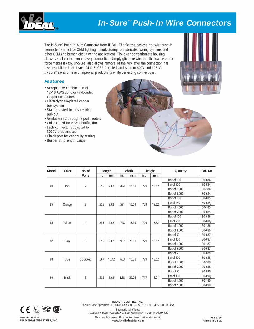
The In-Sure™ Push-In Wire Connector from IDEAL. The fastest, easiest, no-twist push-inconnector. Perfect for OEM lighting manufacturing, prefabricated wiring systems andother OEM and branch circuit wiring applications. The clear polycarbonate housing allows visual verification of every connection. Simply glide the wire in – the low insertionforce makes it easy. In-Sure™ also allows removal of the wire after the connection hasbeen established. UL Listed 94 D-Z, CSA Certified, and rated to 600V and 105°C. In-Sure™ saves time and improves productivity while perfecting connections.
Features• Accepts any combination of
12-18 AWG solid or tin-bonded copper conductors
• Electrolytic tin-plated copper bus system
• Stainless steel inserts restrict pull-out
• Available in 2 through 8 port models• Color-coded for easy identification• Each connector subjected to
3000V dielectric test• Check port for continuity testing• Built-in strip length gauge
Model Color No. of Length Width Height Quantity Cat. No.Ports in. mm in. mm in. mm
Box of 100 30-084Jar of 300 30-084J84 Red 2 .355 9.02 .434 11.02 .729 18.52Box of 1,000 30-184Box of 5,000 30-684Box of 100 30-085Jar of 250 30-085J85 Orange 3 .355 9.02 .591 15.01 .729 18.52Box of 1,000 30-185Box of 5,000 30-685Box of 100 30-086Jar of 200 30-086J86 Yellow 4 .355 9.02 .748 18.99 .729 18.52Box of 1,000 30-186Box of 4,000 30-686Box of 50 30-087Jar of 150 30-087J87 Gray 5 .355 9.02 .907 23.03 .729 18.52Box of 1,000 30-187Box of 5,000 30-687Box of 50 30-088Jar of 100 30-088J88 Blue 6 Stacked .607 15.42 .603 15.32 .729 18.52Box of 1,000 30-188Box of 5,000 30-688Box of 50 30-090Jar of 100 30-090J90 Black 8 .355 9.02 1.38 35.03 .717 18.21Box of 1,000 30-190Box of 2,000 30-690

AFC
Ca
ble
Sys
tem
s C
ab
le C
ata
log
PRODUCT CATALOG
FeaturingAFC's ColorSpec™ ID System
MC TUFF® Cable
MC-Lite® Cable
HCF® Cable
Lighting, Power & Appliance Whips
Temp-Lites™

Application(s) NEC® Type AC Type MC Type MOF
Hospitals, 517.13***** HCF-90, HCF-Lite Fire Alarm/Control
Nursing Homes, 250.118
Health Care Facilities
Places of Assembly* 518 HCF-90, HCF-Lite MC, MC-Lite, MC TUFF,
Fire Alarm/Control, Super Neutral,
Home Run, MC/OF, MC TUFF IG
Fire Alarm Systems, 760, 725.8(B) Fire Alarm/Control
Remote Control Circuits
Under Computer Room 330, 645 Super Neutral, MC TUFF IG
Raised Floors, Business
Equipment, Electronic
Discharge Lighting
Direct Burial in Wet, 330.10,*** Parking Deck/Lot
Dry, Oily Areas**
Multi-conductor Runs, 330 MC, MC-Lite, MC TUFF,
Commercial/Industrial/Utility Super Neutral, Home Run,
MC TUFF IG, Parking Deck/Lot
Robotics, Video Conferencing, 770 MC/OF MOF
Closed-Circuit TV, Factory
Automation
Redundant Ground 250.118, HCF-90, HCF-Lite MC TUFF IG
517.13, 645
Environmental 300.22(C), AC-90, AC-Lite, MC, MC-Lite, MC TUFF, MOF
Air-Handling Spaces 760.71(D)**** HCF-90, HCF-Lite Fire Alarm/Control, Super Neutral,
Home Run, MC/OF, MC TUFF IG
Branch Circuits in Hotels 320, 330 AC-90, AC-Lite MC, MC-Lite, MC TUFF
& Multi-family Dwellings
Office Partition Furniture 605 Super Neutral, MC TUFF IG
Parking Decks, Lots, Garages 330.10*** Parking Deck/Lot
Air Conditioners, Factory 330, 350, 356 Parking Deck/Lot
Installations with Wet, Dirty,
Oily Conditions
Lighting Whips, Motor Leads 320, 330, 348 AC-90, AC-Lite MC, MC TUFF, MC-Lite
2 AFC Cable Systems800-757-6996 www.afcweb.com
Cable Applications Chart
* Over 100 People
** Also hazardous locations up to Class 1, Div. 2
*** Also 230.43, 511.7, 513.7(A), 514.7, 515.7(A), 516.7(A)
**** Fire Alarm/Control Cable Only
***** HCF cables may not be used on emergency circuits in a health care setting. - Review NEC 517.30 (C)(3)(3)
NOTE: Local electrical codes may differ. Please consult appropriate authority.
THIS CHART HAS BEEN PREPARED AS A CONVENIENT REFERENCE TO SOME OF OUR PRODUCTS' MOST COMMON APPLICATIONS.
FOR MORE DETAILED INFORMATION, REFER TO THE APPROPRIATE SECTION OF THIS BROCHURE AND THE NEC.®

MC
3800-757-6996 www.afcweb.comAFC Cable Systems
Type MC Metal Clad CablesType MC Cables – Uses Permitted:
The uses permitted for MC cable are governed by NEC®
Article 330 and any applicable local codes. Please referto NEC® Article 330 and your local authority havingjurisdiction for additional information.
• Where not subject to physical damage; For services, feeders and branch circuits
• For power, lighting, control and signalcircuits
• Indoors, exposed or concealed
• Outdoors or in wet locations where thearmor has an overall outer, moistureresistant PVC jacket and the conductors are wet rated
• Direct buried or in concrete encasementwhere identified for such use (ParkingDeck/Lot Cable™)
• Under raised floors, above suspendedceilings and in other environmental air-handling spaces per NEC 300.22(C)
• In places of assembly
• In cable tray or as open runs
• In locations classified as hazardous aspermitted in NEC Articles 501, 502, 503,504, and 505
• As aerial cable on a messenger
Type MC Cables – Uses Not Permitted:
• Where exposed to destructive corrosiveconditions unless the metallic sheath issuitable for the conditions or is protected by material suitable for the conditions
Type MC cables have 2 or more solid or stranded copper conductors in
sizes 18 AWG and larger.
The construction of AFC’s 600 Volt MC cable consists of copper circuit
and grounding conductors covered with thermoplastic insulation, an
overall polypropylene cable assembly tape and an outer galvanized steel
or aluminum interlocked armor.
The armor of interlocked Type MC cable is not an equipment grounding
means. Type MC cable requires a bare or green grounding conductor.
Type MC cable should be cut with an armored cable rotary cutter.
Rotary cutters have many advantages over other methods. Nicking and
cutting of the conductors is eliminated and the cuts can be made
quickly and safely.
In addition to our standard MC products, AFC offers lightweight
steel MC TUFF® and MC in a variety of specialty configurations, most
featuring the time saving ColorSpec™ ID System. These configurations,
specialty cables, are designed for applications such as fire alarm circuits,
direct burial or modular office furniture. This section describes the
different varieties of MC cable offered by AFC.
For more information about the proper use andapplication of AC & MC cables, visit AFC Universityon the Internet at www.afcweb.com/afcu
NEC® is a registered trademark of the National Fire Protection Association

MC
8 AFC Cable Systems800-757-6996 www.afcweb.com
Product Codes, Trade Sizes, Conductors, Packaging & Weights
Grounding Approx. Armor Product Code Conductor Length (feet) Weight/1000 Minimum
Coil Reel Trade Size AWG Coil Reel Feet (lbs.) O.D. (inches)
1701B42T00 1701B60T00 14-2 Solid 14 250' 1000' 117 0.470
1702B42T00 1702B60T00 14-3 Solid 14 250' 1000' 140 0.480
1703B42T00 1703B60T00 14-4 Solid 14 250' 1000' 164 0.510
1704B42T00 1704B60T00 12-2 Solid 12 250' 1000' 147 0.495
1705B42T00 1705B60T00 12-3 Solid 12 250' 1000' 186 0.530
1706B42T00 1706B60T00 12-4 Solid 12 250' 1000' 223 0.565
1758B42T00 1758B60T00 12-2 Stranded 12 250' 1000' 152 0.495
1759B42T00 1759B60T00 12-3 Stranded 12 250' 1000' 191 0.530
1760B42T00 1760B60T00 12-4 Stranded 12 250' 1000' 225 0.565
1707B32T00 — 10-2 Solid 10 125' — 222 0.560
1708B32T00 — 10-3 Solid 10 125' — 268 0.600
1709B32T00 — 10-4 Solid 10 125' — 313 0.645
1707B42T00 1707B60T00 10-2 Solid 10 250' 1000' 222 0.560
1708B42T00 1708B60T00 10-3 Solid 10 250' 1000' 268 0.600
1709B42T00 1709B60T00 10-4 Solid 10 250' 1000' 313 0.645
1761B32T00 — 10-2 Stranded 10 125' — 227 0.560
1762B32T00 — 10-3 Stranded 10 125' — 269 0.600
1763B32T00 — 10-4 Stranded 10 125' — 319 0.645
1761B42T00 1761B60T00 10-2 Stranded 10 250' 1000' 227 0.560
1762B42T00 1762B60T00 10-3 Stranded 10 250' 1000' 269 0.600
1763B42T00 1763B60T00 10-4 Stranded 10 250' 1000' 319 0.645
Specialty Colors
1704B42T04 1704B60T04 12-2 Solid (red, white) 12 250' 1000' 147 0.495
1704B42T05 1704B60T05 12-2 Solid (blue, white) 12 250' 1000' 147 0.495
1705B42T04 1705B60T04 12-3 Solid (red, blue, white) 12 250' 1000' 147 0.495
1705B42T05 1705B60T05 12-3 Solid (black, blue, white) 12 250' 1000' 147 0.495
1707B42T04 1707B60T04 10-2 Solid (red, white) 10 250' 1000' 222 0.560
1707B42T05 1707B60T05 10-2 Solid (blue, white) 10 250' 1000' 222 0.560
1708B42T04 1708B60T04 10-3 Solid (red, blue, white) 10 250' 1000' 268 0.600
1708B42T05 1708B60T05 10-3 Solid (black, blue, white) 10 250' 1000' 268 0.600
MC TUFF® Lightweight Steel Metal Clad Cable(120 Volt colors) Technical Specifications
NOTE: All dimensions and weights are subject to normal manufacturing tolerances. WARNING: DO NOT RE-IDENTIFY CONDUCTOR COLORS.
Additional black stripe denotes 2 conductor cable
Additional black and red stripe denotes 3 conductor cable
Additional black, red and light blue stripes denote 4 conductor cable
Additional red and white stripesdenote special 2 conductor cable
Additional light blue and white stripesdenote special 2 conductor cable
Additional red, light blue and whitestripes denote special 3 conductor cable
Additional black, light blue and whitestripes denote special 3 conductor cable
Galvanized Steel Armor(Color-Coded Blue) Assembly Tape Copper
Conductors
Nylon ThermoplasticTHHN Insulation
CopperGround
Specification Description
Specification MC-TUFF ColorSpec™ ID System
Armor Galvanized Interlocking Steel Strip
(blue striped)
Conductors Solid/Stranded Copper (see below)
Conductor THHN/THWN (XHHW available by
Insulation special order subject to lead time and
minimum quantities)
Assembly Covering Polypropylene Tape
Maximum
Temperature 90°C (dry)
Rating
Grounding One grounding means – Insulated
Green Grounding Conductor
Neutral Conductor White
Maximum 600V
Voltage Rating
References & Ratings• U.L. 83, 1479, 1569, 1581,
File Reference E80042
• NEC 230.43, 300.22(C), 392, 396,
330, 518, 520, 530, 645
• Federal Specification A-A-59544
(formerly J-C-30B)
• Meets all applicable OSHA and
HUD Requirements
• May be surface mounted, fished and/or embedded in plaster
• Cable Tray installations per NEC
• U.L. Classified 1, 2 and 3-hour Through-Penetration Fire Wall File R-14929
• Environmental Air-Handling Space installation
AFC’s ColorSpec™ ID System
SET SCREW CONNECTORS MAY BE USED WITH STEEL CABLES, SEE CONNECTOR CROSS-REFERENCE GUIDE PAGE 30 FOR DETAILS.

MC
9800-757-6996 www.afcweb.comAFC Cable Systems
Type MC Steel Metal Clad Cable (8 AWG-2 – 4/0 AWG-4 ) Technical Specifications
Galvanized SteelInterlocked Armor Assembly Tape
Stranded CopperConductors
CopperGround
Nylon ThermoplasticTHHN Insulation
Specification Description
Specification MC
Armor Galvanized Interlocking Steel Strip
Conductors Stranded Copper
Conductor THHN/THWN
Insulation
Assembly Polypropylene Tape
Covering
Maximum
Temperature 90°C (dry)
Rating
Grounding One grounding means – may be insulated
or bare, see chart below
Neutral Conductor White
Maximum 600V
Voltage Rating
References & Ratings• U.L. 83, 1479, 1569, 1581, File Reference E80042
• NEC 230.43, 300.22(C), 392, 396, 330, 518, 520, 530, 645
• Federal Specification A-A-59544 (formerly J-C-30B)
• Meets all applicable OSHA and HUD Requirements
• Cable Tray installations per NEC
• U.L. Classified 1, 2 and 3-hour Through-Penetration Fire Wall File R-14929
• Environmental Air-Handling Space installation
Product Codes, Trade Sizes, Conductors, Packaging & Weights
Grounding Approx. Armor Product Code Conductor Length (feet) Weight/1000 Minimum
Coil Reel Trade Size AWG Coil Reel Feet (lbs.) O.D. (inches)
Stock Items
1715-40-00 1715-45-00 8-2 Stranded 10 solid 200' 500' 329 0.635
1716-40-00 1716-45-00 8-3 Stranded 10 solid 200' 500' 432 0.685
1717-32-00 1717-45-00 8-4 Stranded 10 solid 125' 500' 511 0.835
1719-32-00 1719-45-00 6-2 Stranded 8 125' 500' 462 0.795
1720-32-00 1720-45-00 6-3 Stranded 8 125' 500' 594 0.855
1721-30-00 1721-45-00 6-4 Stranded 8 100' 500' 860 0.945
1724-30-00 1724-45-00 4-3 Stranded 8 100' 500' 985 1.035
1725-30-00 1725-45-00 4-4 Stranded 8 100' 500' 1195 1.135
1728-30-00 1728-45-00 3-3 Stranded 6 100' 500' 1070 1.025
1729-30-00 1729-45-00 3-4 Stranded 6 100' 500' 1260 1.120
1726-30-00 1726-45-00 2-3 Stranded 6 100' 500' 1340 1.180
1727-30-00 1727-45-00 2-4 Stranded 6 100' 500' 1640 1.295
1737-30-00 1737-45-00 1-3 Stranded 6 100' 500' 1530 1.185
1738-99-00 1738-99-00 1-4 Stranded 6 †† †† 1930 1.350
1770-99-00 1750-99-00 1/0-3 Stranded bare #6 †† †† 1780 1.255
1771-99-00 1751-99-00 1/0-4 Stranded bare #6 †† †† 2220 1.390
1772-99-00 1753-99-00 2/0-3 Stranded bare #6 †† †† 2095 1.350
1773-99-00 1754-99-00 2/0-4 Stranded bare #6 †† †† 2650 1.520
1774-99-00 1740-99-00 3/0-3 Stranded bare #4 †† †† 2580 1.520
1775-99-00 1741-99-00 3/0-4 Stranded bare #4 †† †† 3245 1.690
1776-99-00 1743-99-00 4/0-3 Stranded bare #4 †† †† 3040 1.580
1777-99-00 1744-99-00 4/0-4 Stranded bare #4 †† †† 3855 1.770
NOTE: All dimensions and weights are subject to normal manufacturing tolerances.
†† Cut to order.
XHHW INSULATION BY SPECIAL ORDER. CALL FOR DETAILS.

MC
10 AFC Cable Systems800-757-6996 www.afcweb.com
Product Codes, Trade Sizes, Conductors, Packaging & Weights
Grounding Approx. Armor Product Code Conductor Length (feet) Weight/1000 Minimum
Coil Reel Trade Size AWG Coil Reel Feet (lbs.) O.D. (inches)
1704B42T01 1704B60T01 12-2 Solid (brown) 12 250' 1000' 147 0.495
1704B42T02 1704B60T02 12-2 Solid (orange) 12 250' 1000' 147 0.495
1704B42T03 1704B60T03 12-2 Solid (yellow) 12 250' 1000' 147 0.495
1704B42T07 1704B60T07 12-2 Solid (purple) 12 250' 1000' 147 0.495
1705B42T01 1705B60T01 12-3 Solid (brown, orange) 12 250' 1000' 186 0.530
1705B42T02 1705B60T02 12-3 Solid (orange, yellow) 12 250' 1000' 186 0.530
1705B42T03 1705B60T03 12-3 Solid (brown, yellow) 12 250' 1000' 186 0.530
1705B42T07 1705B60T07 12-3 Solid (brown, purple) 12 250' 1000' 186 0.530
1706B42T01 1706B60T01 12-4 Solid (brown, orange, yellow) 12 250' 1000' 223 0.565
1706B42T07 1706B60T07 12-4 Solid (brown, yellow, purple) 12 250' 1000' 223 0.565
1758B42T01 1758B60T01 12-2 Stranded (brown) 12 250' 1000' 152 0.495
1758B42T02 1758B60T02 12-2 Stranded (orange) 12 250' 1000' 152 0.495
1758B42T03 1758B60T03 12-2 Stranded (yellow) 12 250' 1000' 152 0.495
1759B42T01 1759B60T01 12-3 Stranded (brown, orange) 12 250' 1000' 191 0.530
1760B42T01 1760B60T01 12-4 Stranded (brown, orange, yellow) 12 250' 1000' 225 0.565
1707B42T01 1707B60T01 10-2 Solid (brown) 10 250' 1000' 222 0.560
1707B42T02 1707B60T02 10-2 Solid (orange) 10 250' 1000' 222 0.560
1707B42T03 1707B60T03 10-2 Solid (yellow) 10 250' 1000' 222 0.560
1707B42T07 1707B60T07 10-2 Solid (purple) 10 250' 1000' 222 0.560
1708B42T01 1708B60T01 10-3 Solid (brown, orange) 10 250' 1000' 268 0.600
1708B42T02 1708B60T02 10-3 Solid (orange, yellow) 10 250' 1000' 268 0.600
1708B42T03 1708B60T03 10-3 Solid (brown, yellow) 10 250' 1000' 268 0.600
1708B42T07 1708B60T07 10-3 Solid (brown, purple) 10 250' 1000' 268 0.600
1709B42T01 1709B60T01 10-4 Solid (brown, orange, yellow) 10 250' 1000 313 0.645
1709B42T07 1709B60T07 10-4 Solid (brown, yellow, purple) 10 250' 1000' 313 0.645
1761B42T01 1761B60T01 10-2 Stranded (brown) 10 250' 1000' 227 0.560
1762B42T01 1762B60T01 10-3 Stranded (brown, orange) 10 250' 1000' 269 0.600
1763B42T01 1763B60T01 10-4 Stranded (brown, orange, yellow) 10 250' 1000' 319 0.645
MC TUFF® Lightweight Steel Metal Clad Cable(480Y/277 Volt colors) Technical Specifications
NOTE: All dimensions and weights are subject to normal manufacturing tolerances. Other conductor colors available by special order. WARNING: DO NOT RE-IDENTIFY CONDUCTOR COLORS.
Additional brown stripe denotes
2 conductor cable (brown conductor)
Additional orange stripe denotes
2 conductor cable (orange conductor)
Additional yellow stripe denotes
2 conductor cable (yellow conductor)
Additional purple stripe denotes
2 conductor cable (purple conductor)
Additional brown and orange stripes
denote 3 conductor cable
Additional orange and yellow stripes
denote 3 conductor cable
Additional brown and yellow stripes
denote 3 conductor cable
Additional brown and purple stripes
denote 3 conductor cable
Additional brown, orange and
yellow stripes denote 4 conductor cable
Additional brown, yellow and purple
stripes denote 4 conductor cable
Galvanized Steel Armor(Color-Coded Blue) Assembly Tape Copper
Conductors
Nylon ThermoplasticTHHN Insulation
Copper Ground
Gray InsulatedNeutral
Specification Description
Specification MC TUFF ColorSpec™ ID System
Armor Galvanized Interlocking Steel Strip
(blue striped)
Conductors Solid or Stranded Copper (see below)
Conductor THHN/THWN (XHHW available by
Insulation special order subject to lead time and
minimum quantities)
Assembly Covering Polypropylene tape
Maximum
Temperature 90°C (dry)
Rating
Grounding One grounding means – Insulated
Green Grounding Conductor
(additional insulated
conductors optional)
Neutral Gray
Conductor
Maximum 600V
Voltage Rating
References & Ratings• U.L. 83, 1479, 1569, 1581,
File Reference E80042
• NEC 230.43, 300.22(C), 392, 396,
330, 518, 520, 530, 645
• Cable Tray installations per NEC
• Federal Specification A-A-59544
(formerly J-C-30B)
• Meets all applicable OSHA and HUD requirements
• May be surfaced mounted and embedded in plaster
• Environmental Air-Handling Space installation
• U.L. Classified 1, 2 and 3-hour Through-Penetration Fire Wall File R-14929
AFC’s ColorSpec™ ID System
SET SCREW CONNECTORS MAY BE USED WITH STEEL CABLES, SEE CONNECTOR CROSS-REFERENCE GUIDE PAGE 32 FOR DETAILS.

Flex • AC • MC
Arlington Industries, Inc. www.aifittings.com • E-mail: [email protected]/233-4717 • FAX 570/562-0646
SeePages E-1 to E-4
38AST
40AST
45AST
50AST
Catalog Nos. 3810AST, 383810AST, 38AST, 38A, 380ST, 380AST, 3838AST, 3890AST
MC/HCF Cable Steel and Aluminum
AC/HCF Cable Steel and Aluminum
MCI-A (MCAP Cable) 3810AST & 383810AST
MCI-A (HCF MCAP Cable) 3810AST & 383810AST
Flexible Metal ConduitSteel and Aluminum (Regular and Reduced Wall)
MC Cable Continuous Corrugated Aluminum
CABLE TYPE CABLE RANGE
14/4, 12/2, 12/3, 12/4, 10/2
14/2, 14/3, 14/4, 12/2, 12/3, 12/4,10/2
14/2, 14/3, 14/4, 12/2, 12/3, 12/4,10/2
3/8" Trade SizeCSA Only - Use Anti-ShortBushing
Catalog Nos. 4010AST, 404010AST, 40AST,400AST, 4040AST, 4090AST
MC/HCF Cable Steel and Aluminum
AC/HCF Cable Steel and Aluminum
MCI-A (MCAP Cable) 4010AST & 404010AST
MCI-A (HCF MCAP Cable) 4010AST & 404010AST
Flexible Metal ConduitSteel and Aluminum (Regular and Reduced Wall)
MC Cable Continuous Corrugated Aluminum
CABLE TYPE CABLE RANGE14/2 w/gr.,14/4, 12/2 w/gr.,12/3, 12/3 w/gr., 10/2 w/gr., 10/3
12/2, 12/3, 12/4 10/2, 10/3, 10/4
14/4, 12/2 w/gr.,12/3, 12/4, 10/2 w/gr., 10/3
3/8" Trade SizeCSA Only - Use Anti-ShortBushing
Catalog Nos. 45AST, 50AST, 5090AST
MC/HCF Cable Steel and Aluminum
AC/HCF Cable Steel and Aluminum
Flexible Metal ConduitSteel and Aluminum (Regular and Reduced Wall)
CABLE TYPE CABLE RANGE
10/3to
6-2
—
8/3 to
4-2
1/2" Flex
45AST 50AST, 5090AST
• No Tools Required to Install• Saves Time and Money• Easy to Remove
PATENTED/PATENTS PENDING.
MCAP and HCF MCAP are registered trademarks of the Southwire® Company.
THEWIDESTCABLE RANGESFOR FLEX • AC • MC • HCF • MCI-A CABLE!
R
R
For overlapping cable ranges, use the larger fitting foreasier cable insertion
119575-LngfrdE 8/10/07 8:01 PM Page ii

CATALOG UPC/DCI/NAED TRADE KO UNIT STD DIM DIM DIM DIM CABLENUMBER MFG #01 8997 SIZE SIZE PKG PKG A B C D RANGE
40AST 00041 3/8 1/2 50 500 1.410 .850 .405 1.000 .485-.612400AST 40347 3/8 1/2 50 500 1.280 .850 .400 1.000 .485-.61250AST 72300 1/2 1/2 50 500 1.660 1.130 .560 1.244 .860-.920
Refer to chart on page E-25 for a list of cable types.Concrete tight when taped.Flexible metal conduit, CSA listed with anti-short bushing (UL not applicable).SNAP-TITE® and SNAP2IT® products have been tested and listed by UL in accordance with UL’s ground fault requirements. For additional information see page 6.PATENTED. ADDITIONAL PATENTS PENDING.
CATALOG UPC/DCI/NAED TRADE KO UNIT STD DIM DIM DIM DIM CABLENUMBER MFG #01 8997 SIZE SIZE PKG PKG A B C D RANGE
38AST* 00070 3/8 1/2 50 500 1.410 .850 .405 1.000 .405-.61238A* 00038 3/8 1/2 50 500 1.410 .850 .405 1.000 .405-.612380ST 00381 3/8 1/2 50 500 1.280 .850 .400 1.000 .405-.612380AST* 00382 3/8 1/2 50 500 1.280 .850 .400 1.000 .405-.61245AST* 00045 1/2 1/2 50 500 1.660 1.130 .560 1.244 .590-.840
*Provided with insulated throat.
E-1 Flex • AC • MC
Arlington Industries, Inc.www.aifittings.com • E-mail: [email protected]/233-4717 • FAX 570/562-0646
380AST
R
R
E18304 LR49636
R
R
E18304 LR49636
SNAP2IT Connectors are EASY to Install... And EASY to Remove...
RED TINTING means‘OPEN TANG’ Design! It gives you more room inside the fitting for easy insertion of wires. The redesigned front end makes it easier than ever to snap the fitting into box!
COMPARE...
SNAP2IT®
ConnectorsZinc die-cast. For MC/HCF steeland aluminum cable • AC/HCFsteel and aluminum cable •Flexible metal conduit steel andaluminum (regular and reducedwall) • MC cable continuous corrugated aluminum.
FOR
EASIER MC/AC
INSTALLATIONS...
38AST38A
DC
B
A38AST
Using ascrewdriver,lift the ringand twistoff.
With Insulated Throat and Red Tinted Inside Clip38AST
40AST
Just snaponto cableand snapinto box!
NO TOOLS!• Safe and fast installations• Saves about 17 seconds
per fitting!• Competitively priced
38AST 40AST
See
3810AST & 4010AST
on Page E-2
119575-LngfrdE 8/10/07 8:01 PM Page 1

E-3 Flex • AC • MC
Arlington Industries, Inc.www.aifittings.com • E-mail: [email protected]/233-4717 • FAX 570/562-0646
*Provided with insulated throat.†Provided with insulated throat and red tinted inside clips. See comparison on page E-1.Refer to chart on page E-25 for a list of cable types.Concrete tight when taped.SNAP-TITE® and SNAP2IT® products have been tested and listed by UL in accordance with UL’s ground fault requirements. For additional information see page 6.PATENTED. ADDITIONAL PATENTS PENDING.
CATALOG UPC/DCI/NAED TRADE KO UNIT STD DIM DIM DIM DIM CABLENUMBER MFG #01 8997 SIZE SIZE PKG PKG A B C D RANGE
3838ST 10935 3/8 1/2 25 100 1.912 1.738 .970 .620 (2).405-.612
3838AST* 36230 3/8 1/2 25 100 1.962 1.738 .970 .620 (2).405-.612
4040AST† 40351 3/8 1/2 25 100 1.962 1.738 .970 .620 (2).485-.612
R
R
E18304 LR49636
A C
D
B
No Tools Required...Fully Assembled!Snap cables into connector andsnap assembly into box orfixture.
SNAP2IT® DuplexConnectorsZinc die-cast. For MC/HCF steeland aluminum cable • AC/HCFsteel and aluminum cable •Flexible metal conduit steel andaluminum (regular and reducedwall) • MC cable continuous corrugated aluminum.
383810AST
CATALOG UPC/DCI/NAED TRADE KO UNIT STD DIM DIM DIM DIM CABLENUMBER MFG #01 8997 SIZE SIZE PKG PKG A B C D RANGE
383810AST 10937 3/8 1/2 25 100 2.398 2.035 .840 .624 (2).370-.490
404010AST† 40533 3/8 1/2 25 100 2.398 2.165 .840 .624 (2).440-.612
404010AST
†Provided with red tinted inside clips so you candifferentiate a 383810AST from a 404010AST.Refer to chart on page E-25 for a list of cable types.Refer to chart on page E-26 for MCI-A (MCAP™ and HCF MCAP™) cable ranges.Concrete tight when taped.SNAP-TITE® and SNAP2IT® products have been tested and listed by UL in accordance with UL’s ground fault requirements. For additional information see page 6.PATENT PENDING.
R
R
E18304 LR49636
A
C
D
B
SNAP2IT® DuplexConnectors withInsulated ThroatZinc die-cast. For MC/HCF steeland aluminum cable • AC/HCFsteel and aluminum cable •Flexible metal conduit steel andaluminum (regular and reducedwall) • MC cable continuous corrugated aluminum • MCI-A(MCAP™ and HCF MCAP™) cable.
New!
Secure hold – Easy cable insertion!
FOR THE
WIDEST TOTAL
CABLE RANGES
MCAP and HCF MCAP are registered trademarks of the Southwire® Company.
Simply snap the cable into the fitting andsnap it into the box...no tools needed! The screw only holds the clip in place.
FOR
EASIER MC/AC
INSTALLATIONS...
See
383810AST & 404010AST
Above
119575-LngfrdE.2 9/11/07 12:14 AM Page 3

E-14Flex • AC • MC
Arlington Industries, Inc. www.aifittings.com • E-mail: [email protected]/233-4717 • FAX 570/562-0646
CATALOG UPC/DCI/NAED TRADE KO UNIT STD DIM DIM DIM CABLE END STOPNUMBER MFG #01 8997 SIZE SIZE PKG PKG A B C RANGE DIAMETER
SG38AST*‡ 80144 3/8 1/2 50 500 1.203 .555 1.077 .405-.612 .400
SG380AST*‡ 80148 3/8 1/2 50 500 1.145 .555 1.077 .405-.612 .400 x .580
SG50ST‡ 80150 1/2 1/2 50 500 1.458 .510 1.235 .710-.910 .620
SG50AST*‡ 17501 1/2 1/2 50 500 1.145 .555 1.277 .710-.910 .620
SG75ST 18080 3/4 3/4 20 200 1.495 .510 1.570 .840-1.110 .820
SG75AST* 17755 3/4 3/4 20 200 1.540 .555 1.570 .840-1.110 .820
*Provided with insulated throat.‡Also for MCI-A (MCAP™ and HCF MCAP™) cable. Refer to page E-26 for cable ranges.Refer to chart on page E-25 for a list of cable types.Concrete tight when taped.For cables smaller than .405" see L16 and L16ST on page E-5.SNAP-TITE® products have been tested and listed by UL in accordance with UL’s ground fault requirements. For additional information see page 6.PATENTED.
CATALOG UPC/DCI/NAED TRADE KO UNIT STD DIM DIM DIM CABLENUMBER MFG #01 8997 SIZE SIZE PKG PKG A B C RANGE
SG3838ST 80152 3/8 1/2 25 100 .455 1.560 .780 (2) .445-.612SG3838AST* 36210 3/8 1/2 25 100 .605 1.610 .780 (2) .445-.612*Provided with insulated throat.Refer to chart on page E-24 for a list of cable types.Refer to chart on page E-26 for MCI-A (MCAP™ and HCF MCAP™) cable ranges.Concrete tight when taped.With independent securing of the cables, you can use two different size cables.SNAP-TITE® products have been tested and listed by UL in accordance with UL’s ground faultrequirements. For additional information see page 6.PATENTED.
SADDLEGRIP®
SNAP-TITE®
ConnectorsFor aluminum and steel Flex •AC • MC cable. Zinc die-cast.
SG38AST
SG380AST
R
R
E60812 LR49636
SG380AST SG38AST
R
R
E60812 LR49636
DuplexSADDLEGRIP®
SNAP-TITE®
ConnectorsZinc die-cast. For aluminumand steel Flex • AC • MCcable • MCI-A (MCAP™ andHCF MCAP™) cable.
A
B
C
A
B
C
MCAP and HCF MCAP are registered trademarks of the Southwire® Company.
119575-LngfrdE 8/10/07 8:01 PM Page 14