Embed Size (px)
Citation preview

2014 Microchip Technology Inc. DS00001778A-page 1
AN1778
INTRODUCTIONThis application note describes the Class B Safety Software Library routines that detect the occurrences of Faults in a single channel MCU. These routines have been developed in accordance with the IEC 60730 standard to support the Class B certification pro-cess. The routines can be directly integrated with the end user’s application to test and verify the critical functionalities of a controller without affecting the end user’s application.
This application note also describes the Application Programming Interface (API) functions that are available in the Class B Safety Software Library.
The Class B safety software routines can be called periodically at start-up or run time to test the following components:
• CPU Registers• CPU Program Counter• Invariable Memory• Variable Memory• Clock
This application note also outlines various techniques, which are not part of the Class B Safety Software Library, to test components such as external communi-cation, timing, I/O periphery, analog I/O and analog multiplexer.
OVERVIEW OF THE IEC 60730 STANDARD
The IEC 60730 standard defines the test and diagnos-tic methods that ensure the safe operation of the con-trolled equipment used in household appliances. Annex H of the IEC 60730 standard classifies the soft-ware into the following categories (see Appendix B: “IEC 60730-1 Table H.1 (H.11.12.7 of edition 3)”):
• Class A• Class B• Class C
The Class B Safety Software Library implements the important test and diagnostic methods that fall into the Class B category. These methods use various mea-sures to detect and respond to the software-related Faults and errors.
According to the IEC 60730 standard, the controls with functions that fall into the Class B category should have one of the following structures:
• Single Channel with Functional Test In this structure, the Functional test is executed prior to the application firmware execution.
• Single Channel with Periodic Self-Test In this structure, the Periodic tests are embedded within the firmware, and the self-test occurs periodically while the firmware is in Execution mode.
• Dual Channel without ComparisonIn this structure, two independent methods execute the specified operations.
Note: The term ‘IEC 60730 standard’ that isused in this document refers to the “IEC60730-1 ed.5.0” Copyright © 2013 IEC,Geneva, Switzerland. www.iec.ch.
Authors: Veena Kudva, Adrian Aur & Anton AlkhimenokMicrochip Technology Inc.
Note: “The authors thank the InternationalElectrotechnical Commission (IEC) forpermission to reproduce information fromits International Standard IEC 60730-1ed.5.0 (2013). All such extracts are copy-right of IEC, Geneva, Switzerland. Allrights reserved. Further information on theIEC is available from www.iec.ch. IEC hasno responsibility for the placement andcontext in which the extracts and contentsare reproduced by the author, nor is IEC inany way responsible for the other contentor accuracy therein.”
Class B Safety Software Library forPIC® MCUs and dsPIC® DSCs

AN1778
DS00001778A-page 2 2014 Microchip Technology Inc.
SYSTEM REQUIREMENTSThe following system requirement is recommended to run the Class B Safety Software Library:
For the tests that require the independent time slot monitoring, the system hardware must be provided with at least two independent clock sources (e.g., internal oscillator, crystal oscillator and line frequency).
CLASS B SAFETY SOFTWARE LIBRARYThe 16-bit Class B Safety Software Library includes APIs, which are intended to maximize application reliability through Fault detection. These APIs help meet the IEC 60730 standard compliance. The follow-ing tests can be implemented using this library:
• CPU Register Test• Program Counter Test• Invariable Memory (Flash/EEPROM) Test• Variable Memory Test• Clock Test
In the following sections, the test description and the implementation details are discussed for each test. In addition, each section lists the APIs that are required to execute the corresponding test.
CPU Register TestThe CPU Register test implements functional test H.2.16.5, as defined by the IEC 60730 standard. It detects stuck-at Faults in the CPU registers. This ensures that the bits in the registers are not stuck at a value of ‘0’ or ‘1’.
The CPU Register test is a non-destructive test.
This test performs the following major tasks:
1. The contents of the CPU registers to be tested are saved and restored during the test.
2. The registers are tested by first successively writing the binary sequences (length is depen-dent upon architecture), 010101... followed by 101010... into the registers, and then reading the values from these registers for verification.
3. The test returns an error code if the returned values do not match.
API FUNCTIONSThis API function implements the CPU Register test:
CLASSB_CPURegistersTest
Program Counter TestThe Program Counter (PC) test implements the func-tional test H.2.16.5 defined by the IEC 60730 standard. The PC holds the address of the next instruction to be executed.
The test performs the following major tasks:
1. The PC test invokes the functions that are located in the Flash memory at different addresses.
2. These functions reset the error flag.3. The error flag is tested in many places of the
application code.4. If the error flag is cleared, the PC branches to
the correct location.
API FUNCTIONSThe following API functions implement the PC test:
• CLASSB_CPUPCTest()
• CLASSB_CPUPCTestGetResult()
2014 Microchip Technology Inc. DS00001778A-page 3
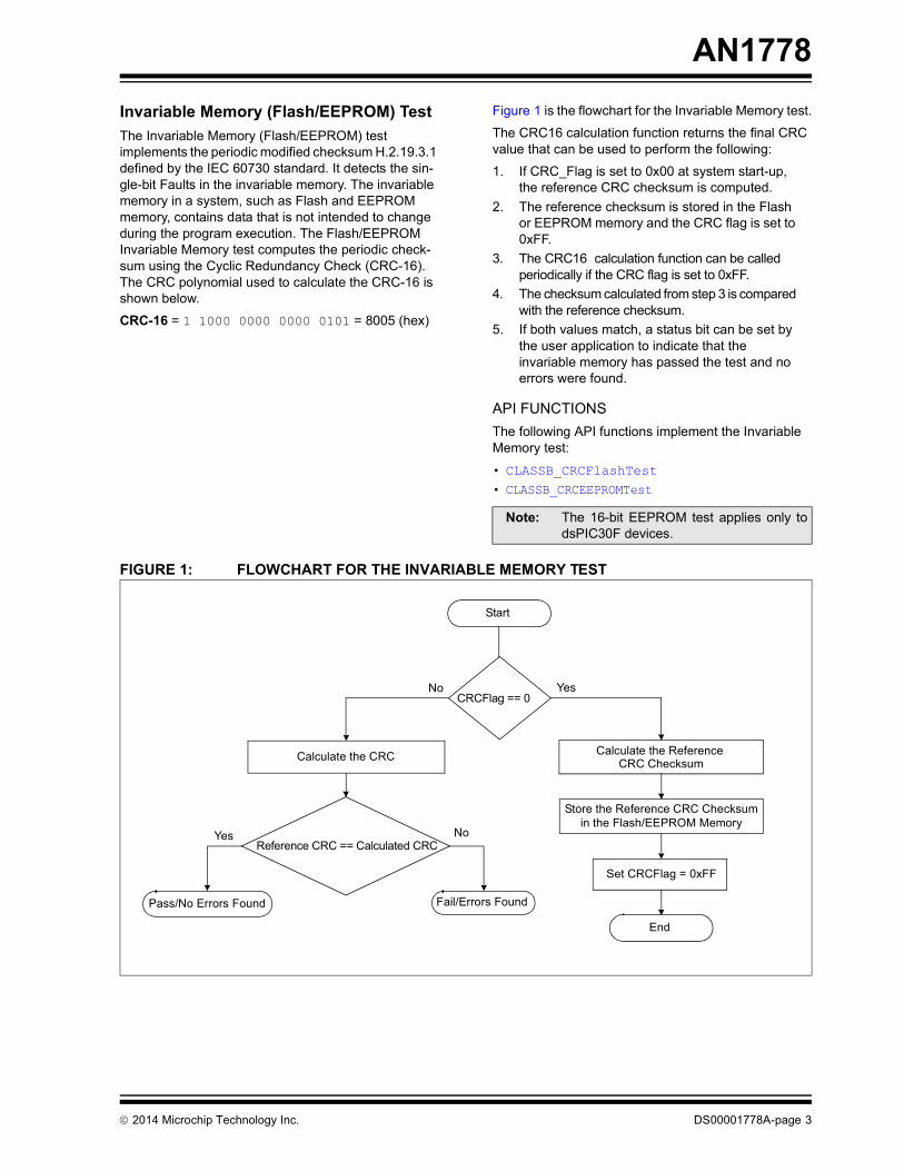
AN1778Invariable Memory (Flash/EEPROM) TestThe Invariable Memory (Flash/EEPROM) test implements the periodic modified checksum H.2.19.3.1 defined by the IEC 60730 standard. It detects the sin-gle-bit Faults in the invariable memory. The invariable memory in a system, such as Flash and EEPROM memory, contains data that is not intended to change during the program execution. The Flash/EEPROM Invariable Memory test computes the periodic check-sum using the Cyclic Redundancy Check (CRC-16). The CRC polynomial used to calculate the CRC-16 is shown below.
CRC-16 = 1 1000 0000 0000 0101 = 8005 (hex)
Figure 1 is the flowchart for the Invariable Memory test.
The CRC16 calculation function returns the final CRC value that can be used to perform the following:
1. If CRC_Flag is set to 0x00 at system start-up, the reference CRC checksum is computed.
2. The reference checksum is stored in the Flash or EEPROM memory and the CRC flag is set to 0xFF.
3. The CRC16 calculation function can be called periodically if the CRC flag is set to 0xFF.
4. The checksum calculated from step 3 is compared with the reference checksum.
5. If both values match, a status bit can be set by the user application to indicate that the invariable memory has passed the test and no errors were found.
API FUNCTIONSThe following API functions implement the Invariable Memory test:
• CLASSB_CRCFlashTest
• CLASSB_CRCEEPROMTest
FIGURE 1: FLOWCHART FOR THE INVARIABLE MEMORY TEST
Note: The 16-bit EEPROM test applies only todsPIC30F devices.
Calculate the CRC
Reference CRC == Calculated CRC
Yes
Yes No
No
Pass/No Errors Found Fail/Errors Found
Calculate the Reference
CRCFlag == 0
Store the Reference CRC Checksumin the Flash/EEPROM Memory
Start
Set CRCFlag = 0xFF
End
CRC Checksum

AN1778
DS00001778A-page 4 2014 Microchip Technology Inc.
Variable Memory TestThe Variable Memory test implements the Periodic Static Memory test H.2.19.6 defined by the IEC 60730 standard. It detects single bit Faults in variable mem-ory. The variable memory contains data, which is intended to vary during program execution. The RAM Memory test is used to determine if any bit of the RAM memory is stuck at ‘1’ or ‘0’. The March Memory and Checkerboard tests are widely used static memory algorithms for checking the DC Faults.
The following tests can be implemented using the Class B Safety Software Library:
• March Test- March C/C- Test- March B Test
MARCH TESTA March test performs a finite set of operations on every memory cell in a memory array. Each operation performs the following tasks:
1. Writes ‘0’ to a memory cell (w0).2. Writes ‘1’ to a memory cell (w1).3. Reads the expected value ‘0’ from a memory
cell (r0).4. Reads the expected value ‘1’ from a memory
cell (r1).
March Test NotationsFigure 2 illustrates the notations that are used in the March test.
FIGURE 2: MARCH TEST NOTATIONS
MARCH C/C- TESTThe March C/C- test is used to detect the following types of Fault in the variable memory:
• Stuck-at Fault• Addressing Fault• Transition Fault • Coupling Fault
The complexity of the March C/C- test is 11n and 10n respectively, where n indicates the number of bits in the memory. This test can be run as either destructive or non-destructive. If run in non-destructive mode buffer space is required to store the contents of the memory to be tested and restored. If needed, this test can be executed at the system start-up before initializing the memory.
Example 1 shows the pseudocode that demonstrates the implementation of the March C test.
API FUNCTIONSThis API function implements the March C/C- test:
CLASSB_RAMMarchCTest
Figure 3 illustrates a March C algorithm.
FIGURE 3: MARCH C ALGORITHM
Arranges the address sequence in ascending order.
Arranges the address sequence in descending order.
Arranges the address sequence in either ascending or descending order.
Indicates a read operation (reads ‘0’ from a memory cell).
Indicates a read operation (reads ‘1’ from a memory cell).
Indicates a write operation (writes ‘0’ to a memory cell).
Indicates a write operation (writes ‘1’ to a memory cell).
:
1
:
0
:
1
:
0
:
:
w
w
r
r
:
})0();0,1();1,0();0(
);0,1();1,0();0(
{
rwrwrr
wrwrw
CMarch
Note: This step can be skipped for C-.

2014 Microchip Technology Inc. DS00001778A-page 5
AN1778EXAMPLE 1: PSEUDOCODE FOR MARCH C TEST /* Ascending: Write 0 */for(i=0;i<=(n-1);i++) x(i)=0;
/* Ascending: Read 0, Write 1 */for(i=0;i<=(n-1);i++){ if (x(i)==0)x(i) =1;else return fail;}
/* Ascending: Read 1, Write 0 */for(i=0;i<=(n-1);i++){ if(x(i)==1) x(i)=0; else return fail;}
/* Standard March C only/* Ascending: Read 0*/if ( minus != 0){ for(i=(n-1);i>=0;i--) { if(x(i)==0) {} else return fail ; }}
/* Descending: Read 0, Write 1*/for(i=(n-1);i>=0;i--){ if(x(i)==0) x(i)=1; else return fail;}
/* Descending: Read 1, Write 0 */for(i=(n-1);i>=0;i--){ if(x(i)==1) x(i)=0; else return fail;
/* Ascending: Read 0 */for(i=(n-1);i>=0;i--){ if(x(i)==0) {} else return fail;}return pass;

AN1778
DS00001778A-page 6 2014 Microchip Technology Inc.
MARCH B TESTThe March B is a non-redundant test that can detect the following types of Fault:
• Stuck-at• Linked Idempotent Coupling• Inversion Coupling
This test is of complexity 17n, where n indicates the number of bits in the memory. This test can be run as either destructive or non-destructive. If run in non-destructive mode buffer space is required to store the contents of the memory to be tested and restored. If needed, this test can be executed at the system start-up before initializing the memory.
Figure 4 illustrates a March B algorithm.
FIGURE 4: MARCH B ALGORITHM
Example 2 shows the pseudocode that demonstrates the implementation of the March B test.
API FUNCTIONSThis API function implements the March B test:
CLASSB_RAMMarchBTest
});1,,0();01,(
);0, ,1();1, ,0();0(
{
wrwr
wrwrw
BMarch
1,r 0, w 0,r 1w 1 w
0, w w1, w0

2014 Microchip Technology Inc. DS00001778A-page 7
AN1778EXAMPLE 2: PSEUDOCODE FOR MARCH B TEST /* Write 0 */
for(i=0;i<=(n-1);i++)
x(i)=0;
/* Ascending: Read 0, Write 1; Read 1, Write 0; Read 0, Write 1 */
for(i=0;i<=(n-1);i++)
{
if(x(i)=0)
{
x(i)==1;
}
else
return fail;
if(x(i)==1)
{
x(i)=0;
}
else
return fail;
if(x(i)==0)
{
x(i)=1;
}
else
return fail;
/* Ascending: Read 1, Write 0; Write 1 */
for(i=0;i<=(n-1);i++)
{
if(x(i)==1)
{
x(i)=0;
x(i)=1;
}
else
return fail;
/* Descending: Read 1, Write 0, Write 1, Write 0 */
for(i=(n-1);i>=0;i--)
{
if(x(i)=1)
{
x(i)=0;
x(i)=1;
x(i)=0;
}
else
return fail;
/* Descending: Read 0, Write 1, Write 0; */}
for(i=(n-1);i>=0;i--)
{
if(x(i)==0)
{
x(i)=1;
x(i)=0;
}
else
return fail;
}
return pass;

AN1778
DS00001778A-page 8 2014 Microchip Technology Inc.
CHECKERBOARD RAM TESTThe Checkerboard RAM test writes the checkerboard patterns to a sequence of adjacent memory locations. This test is performed in units (memory chunks) of 4 bytes. This is a non-destructive memory test.
This test performs the following major tasks:
1. Saves the contents of the memory locations to be tested in the CPU registers.
2. Writes the binary value (length is dependent upon architecture) 101010... to the memory location, ‘N’, and the inverted binary value, 010101..., to the memory location, ‘N+1’, and so on, until the whole memory chunk is filled.
3. Reads the contents of all the memory locations in the current chunk and verifies its contents. If the values match, the function continues; otherwise it stops and returns an error.
4. Step 2 and 3 are repeated by writing the inverted pattern to the same locations.
5. Once a memory chunk is completed the test of the next chunk is started until all of the requested memory area is tested.
API FUNCTIONSThis API function implements the Checkerboard RAM test:
CLASSB_RAMCheckerboardTest
Clock Test According to the IEC 60730 standard, only harmonics and subharmonics of the clock need to be tested. The Clock test implements the independent time slot moni-toring H.2.18.10.4 defined by the IEC 60730 standard. It verifies the reliability of the system clock (i.e., the system clock should be neither too fast nor too slow).
The Clock Test function is used to verify the proper operation of the CPU clock.
This test performs the following major tasks:
1. The independent clock source (or a reference clock source) is required for the test. It can be a secondary oscillator or power line. The refer-ence clock should be connected to a timer such as Timer1.
2. During the test the number of CPU clock cycles per the one reference clock period are counted.
3. If the number of clock cycles is outside a speci-fied range, the function returns an error code.
API FUNCTIONSThis API function implements the Clock test:
CLASSB_ClockTest
Addressing of Variable and Invariable Memory and Internal Data PathFor single chip microcontrollers or digital signal controllers, such as PIC MCUs and dsPIC DSCs, the Periodic Static Memory test is used to test the variable memory, and the periodic checksum is used to test the invariable memory. These tests detect any stuck-at Fault in the internal address bus and internal data path.

2014 Microchip Technology Inc. DS00001778A-page 9
AN1778Addressing Wrong AddressThis test is required only for microcontrollers with an external memory device.
External Communication The IEC 60730 Class B specifications suggest the fol-lowing measures to ensure reliable communication between components:
TRANSFER REDUNDANCYThe transfer redundancy is a Fault/error control technique that protects against coincidental and/or systematic errors in the input and output information. It is achieved by transferring the data between the trans-mitter and receiver. The data is transferred at least twice in succession and then compared.
PROTOCOL TEST The Protocol test is a Fault/error control technique in which the data is transferred to and from the computer components to detect errors in the internal communication protocol.
CRC SINGLE WORD A CRC polynomial is used to calculate the CRC check-sum of the transmitted message. At the transmitting end, this CRC checksum is appended to the message before transmitting it. At the receiving end, the receiver uses the same CRC polynomial to compute the CRC checksum, and compares the computed value with the received value.
TimingThe PIC MCUs and dsPIC DSCs have several dedicated communication interfaces, such as UART, I2C™ and SPI modules. The IEC 60730 Class B specifications suggest that these modules should use time slot monitoring to ensure that the communication occurs at the correct point in time.
Plausibility CheckThe plausibility checks on the I/O periphery, analog multiplexer and A/D convertor can be performed as follows:
I/O PERIPHERY The plausibility check on an I/O pin can be performed by toggling the I/O and checking the state of the pin.
ANALOG MULTIPLEXERTo verify the operation of the analog multiplexer, known voltage values are applied to all channels. These val-ues are read and compared with the applied voltage for verification.
A/D CONVERTERTo test the analog functions of the A/D converter, a known external voltage is applied to the analog inputs. The conversion results are then compared with the applied voltage.

AN1778
DS00001778A-page 10 2014 Microchip Technology Inc.
DescriptionThis function implements the CPU Register test. The test writes the values 0x5555 and 0xAAAA into the CPU registers and then reads the values from these registers for verification. The function returns a non-zero if the values do not match. The results are returned into the W0 register. Therefore the contents are the W0 register are not preserved. The content of the CPU register to be tested is saved and then restored upon the completion of the each register test.
PrototypeCLASSBRESULT CLASSB_CPURegistersTest();
ArgumentsNone
Return ValueCLASSB_TEST_PASS (returned value = 0) – the test finished successfully
CLASSB_TEST_FAIL (returned value != 0) – the test is failed
Source Fileclassb_registers_.s
TABLE 1: RESOURCE REQUIREMENTS
CLASSB_CPURegistersTest
Parameter Requirements
Program Flash Memory 1054 BytesExecution Time 240 Instruction CyclesInterrupts Disabled for 39 Instruction Cycles
2014 Microchip Technology Inc. DS00001778A-page 11
AN1778
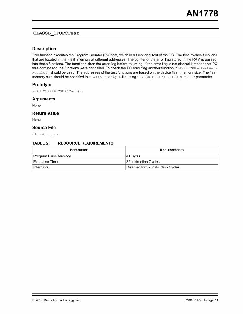
DescriptionThis function executes the Program Counter (PC) test, which is a functional test of the PC. The test invokes functions that are located in the Flash memory at different addresses. The pointer of the error flag stored in the RAM is passed into these functions. The functions clear the error flag before returning. If the error flag is not cleared it means that PC was corrupt and the functions were not called. To check the PC error flag another function CLASSB_CPUPCTestGet-Result() should be used. The addresses of the test functions are based on the device flash memory size. The flash memory size should be specified in classb_config.h file using CLASSB_DEVICE_FLASH_SIZE_KB parameter.
Prototypevoid CLASSB_CPUPCTest();
ArgumentsNone
Return ValueNone
Source Fileclassb_pc_.s
TABLE 2: RESOURCE REQUIREMENTS
CLASSB_CPUPCTest
Parameter Requirements
Program Flash Memory 41 BytesExecution Time 32 Instruction CyclesInterrupts Disabled for 32 Instruction Cycles

AN1778
DS00001778A-page 12 2014 Microchip Technology Inc.
DescriptionThis function checks the result of the PC test done by CLASSB_CPUPCTest() function. This function should be called in many places of the application code, especially before any critical operations.
PrototypeCLASSBRESULT CLASSB_CPUPCTestGetResult();
ArgumentsNone
Return ValueCLASSB_TEST_PASS (returned value = 0) – the test finished successfully
CLASSB_TEST_FAIL (returned value != 0) – the test is failed
Source Fileclassb.h
RemarksNone
TABLE 3: RESOURCE REQUIREMENTS
CLASSB_CPUPCTestGetResult
Parameter Requirements
Program Flash Memory N/AExecution Time N/AInterrupts Enabled

2014 Microchip Technology Inc. DS00001778A-page 13
AN1778
DescriptionThis function implements the Invariable Memory test. It computes the CRC of data starting at startAddress for length bytes using the crcSeed provided. This function returns the final CRC value.
Prototypeuint16_t CLASSB_CRCFlashTest(startAddress, length, crcSeed)
Arguments• startAddress - the first address of the tested memory (must be even number)• length - the byte length of the tested memory (must be even number)• crcSeed - initial value of the CRC check sum
Return Valuecrc_ResultHolds the CRC result
Source Fileclassb_crc.c
RemarksNone
TABLE 4: RESOURCE REQUIREMENTS
CLASSB_CRCFlashTest
Parameter Requirements
Flash Memory 383 BytesExecution Time 160000 Instruction Cycles per KbyteInterrupts Enabled

AN1778
DS00001778A-page 14 2014 Microchip Technology Inc.
DescriptionThe function calculates the CRC check sum for the EEPROM memory region. The variables startAddress and length must be even numbers.
Prototypeuint16_t CLASSB_CRCEEPROMTest (startAddress, length, crcSeed)
Arguments• startAddress - the first address of the tested EEPROM memory in bytes (must be even number)• length - the byte length of the tested EEPROM memory (must be even number)• crcSeed - initial value of the CRC check sum
Return ValueThe function returns the standard 16-bit CRC check sum
RemarksNone
Source Fileclassb_crc.c
TABLE 5: RESOURCE REQUIREMENTS
CLASSB_CRCEEPROMTest
Parameter Requirements
Flash Memory 383 BytesExecution Time 128000 Instruction Cycles per Kbyte Interrupts Enabled

2014 Microchip Technology Inc. DS00001778A-page 15
AN1778
DescriptionThis function implements the March C and March C minus tests for the RAM memory. The variables startAddress and length must be even numbers. This test can be run as either destructive or non-destructive. When the buffer to store the memory content is not specified, it is run in destructive mode and the memory content is not saved. To run in non-destructive mode the buffer address must be defined. The tested RAM region must not cross the storage buffer region. Also this test can be executed at the system start-up before initializing the memory. The CLASSB_-MARCH_C_STARTUP or CLASSB_MARCH_C_MINUS_STARTUP parameters in classb_config.h must be set to non-zero value to run the test at the system start-up. The interrupts are disabled during the test.
PrototypeCLASSBRESULT CLASSB_RAMMarchCTest (startAddress, length, bufferAddress, minus)
Arguments• startAddress - the first address of the tested memory (must be even number)• length - the byte length of the tested memory (must be even number)• bufferAddress - the first address of the buffer to store the tested memory content (must be even number); if
this parameter is NULL then tested memory will be cleared• minus - if the parameter is non-zero, the “minus” algorithm is used.
Return ValueCLASSB_TEST_PASS (returned value = 0) - the test finished successfully
CLASSB_TEST_FAIL (returned value != 0) - the test is failed
RemarksNone
Source Fileclassb_marchc_.s
TABLE 6: RESOURCE REQUIREMENTS
CLASSB_RAMMarchCTest
Parameter Requirements
Memory 1364 BytesExecution Time March C 115,200 Instruction Cycles per Kbyte
March C- 121600 Instruction Cycles per KbyteInterrupts Disabled during the test

AN1778
DS00001778A-page 16 2014 Microchip Technology Inc.
DescriptionThis function implements the March B test for the RAM memory. The variables startAddress and length must be even numbers. This test can be run as either destructive or non-destructive. When the bufferAddress is not speci-fied, it is run in destructive mode and the memory content is not saved. To run in non-destructive mode, the bufferAd-dress must be defined. The tested RAM region must not cross the storage buffer region. Also, this test can be executed at the system start-up before initializing the memory. The CLASSB_MARCH_B_STARTUP parameter in classb_config.h must be set to non-zero value to run the test at the system start-up. The interrupts are disabled during the test.
PrototypeCLASSBRESULT CLASSB_RAMMarchBTest(startAddress, length, bufferAddress);
Arguments• startAddress - the first address of the tested memory (must be even number)• length - the byte length of the tested memory (must be even number)• bufferAddress - the first address of the buffer to store the tested memory content (must be even number); if
this parameter is NULL then tested memory will be cleared
Return ValueCLASSB_TEST_PASS (returned value = 0) - the test finished successfully
CLASSB_TEST_FAIL (returned value != 0) - the test is failed
RemarksNone
Source Fileclassb_marchb_.s
TABLE 7: RESOURCE REQUIREMENTS
CLASSB_RAMMarchBTest
Parameter Requirements
Flash Memory 2003 BytesExecution Time 192000 Instruction Cycles per KbyteInterrupts Disabled during the test

2014 Microchip Technology Inc. DS00001778A-page 17
AN1778
DescriptionThis function implements the Checkerboard test on the RAM memory. The test is performed on length bytes starting at startAddress. The variable length must be divisible by 4.
PrototypeCLASSBRESULT CLASSB_RAMCheckerboardTest (startAddress, length)
Arguments• startAddress - the first address of the tested memory (must be even number)• length - the byte length of the tested memory (must be divisible by 4 bytes).
Return ValueCLASSB_TEST_PASS (returned value = 0) - the test finished successfully
CLASSB_TEST_FAIL (returned value != 0) - the test is failed
RemarksNone.
Source Fileclassb_checkerboard_.s
TABLE 8: RESOURCE REQUIREMENTS
CLASSB_RAMCheckerboardTest
Parameter Requirements
Flash Memory 190 Bytes Stack 8000 Instruction Cycles per KbyteInterrupts Disabled for 24 Instruction Cycles

AN1778
DS00001778A-page 18 2014 Microchip Technology Inc.
DescriptionThis function implements the Clock test. It is used to verify that the CPU clock source is operating within the acceptable frequency tolerance. The reference clock (e.g., external crystal or line frequency) needs to be connected to a timer. The timer must be initialized by the application code to count the reference clock pulses. The period register must be set to the maximum value. The address of the timer counter register must be specified in classb_config.h using the com-pile time option CLASSB_CLOCK_TEST_TIMER_ADDRESS. The compile option CLASSB_CLOCK_TEST_TIME_MS in the classb_config.h file defines the test time – it can be about 20 ms if the clock is between 1-32 MHz and the reference clock is 50 Hz-33 kHz. Interrupts are disabled during the test.
PrototypeCLASSB_ClockTest (uint32_t clockFrequency, uint32_t referenceFrequency, uint16_t tolerance)
Arguments• clockFrequency - frequency of the clock source• referenceFrequency - frequency of the reference clock (such as power line or secondary oscillator)• tolerance - maximum valid frequency tolerance, can be from 1(0.1%) to 100(10%)
Return Value CLASSB_TEST_PASS (returned value = 0) - the test finished successfully
CLASSB_TEST_FAIL (returned value != 0) - the test is failed
RemarksNone.
Source Fileclassb_clock_.s
classb_clock.c
TABLE 9: RESOURCE REQUIREMENTS
CLASSB_ClockTest
Parameter Requirements
Flash Memory 633 BytesExecution Time 160000-640000 Instruction CyclesInterrupts Disabled during the test

2014 Microchip Technology Inc. DS00001778A-page 19
AN1778
SUMMARYThis application note describes how to implement various diagnostic measures proposed by the IEC 60730 standard. These measures ensure the safe operation of controlled equipment that falls under the Class B category. In addition, this application note also describes the different APIs that are available in the Class B Safety Software Library. These APIs can be directly integrated with the end user’s application to test and verify the critical functionalities of a controller and are intended to maximize the application reliability through Fault detection. When implemented on a dsPIC DSC or PIC MCU, these APIs help meet the IEC 60730 standard’s requirements.
Microchip has developed the Class B Safety Software Library to assist you in implementing the safety software routines. Contact your Microchip sales or application engineer if you would like further support.
REFERENCES• IEC 60730 Standard, “Automatic Electrical
Controls for Household and Similar Use”, IEC 60730-1 ed.5, 2013
• Bushnell, M., Agarwal, V. “Essentials of Electronic Testing for Digital, Memory, and Mixed-Signal VLSI Circuits” New York: Springer, 1st ed. 2000. Corr. 2nd printing, 2005
• Wu, C. “Memory Testing” • Wu, C. “RAM Fault Models and Memory Testing” • Suk, D.S. and Reddy, S.M. “A March Test for
Functional Faults in Semiconductor Random-Access Memories”, lEEE Trans. Computers, Vol. C-30, No. 12, 1981, pp. 982-985

AN1778
DS00001778A-page 20 2014 Microchip Technology Inc.
APPENDIX A: SOURCE CODE
All of the software covered in this application note is available as a single zip file. This archive can be downloaded from the Microchip corporate web site at:
www.microchip.com/classb
Software License Agreement
The software supplied herewith by Microchip Technology Incorporated (the “Company”) is intended and supplied to you, the Company’s customer, for use solely and exclusively with products manufactured by the Company.
The software is owned by the Company and/or its supplier, and is protected under applicable copyright laws. All rights are reserved. Any use in violation of the foregoing restrictions may subject the user to criminal sanctions under appli-cable laws, as well as to civil liability for the breach of the terms and conditions of this license.
THIS SOFTWARE IS PROVIDED IN AN “AS IS” CONDITION. NO WARRANTIES, WHETHER EXPRESS, IMPLIED OR STATUTORY, INCLUDING, BUT NOT LIMITED TO, IMPLIED WARRANTIES OF MERCHANTABILITY AND FIT-NESS FOR A PARTICULAR PURPOSE APPLY TO THIS SOFTWARE. THE COMPANY SHALL NOT, IN ANY CIR-CUMSTANCES, BE LIABLE FOR SPECIAL, INCIDENTAL OR CONSEQUENTIAL DAMAGES, FOR ANY REASON WHATSOEVER.

2014 Microchip Technology Inc. DS00001778A-page 21
AN1778
APPENDIX B: IEC 60730-1 TABLE H.1 (H.11.12.7 OF EDITION 3)The following table is reproduced with the permission of the International Electrotechnical Commission (IEC). IEC 60730-1 ed.5 “Copyright © 2013 IEC, Geneva, Switzerland. www.iec.ch”.TABLE B-1: Table H.1 (H.11.12.7 of edition 3) – Acceptable measures to address fault/errorsa Componentb Fault/error Software Class Example of acceptable measuresc d e Definitions
B C
1. CPU1.1Registers Stuck at
DC fault
rq
rq
Functional test, or periodic self-test using either: – static memory test, or – word protection with single bit
redundancyComparison of redundant CPUs by either:– reciprocal comparison – independent hardware comparator, or internal error detection, or redundant memory with comparison, or periodic self-tests using either– walkpat memory test – Abraham test – transparent GALPAT test; or word protection with multi-bit redundancy,orstatic memory test and word protection with single bit redundancy
H.2.16.5H.2.16.6H.2.19.6H.2.19.8.2
H.2.18.15H.2.18.3H.2.18.9H.2.19.5
H.2.19.7H.2.19.1H.2.19.2.1H.2.19.8.1
H.2.19.6H.2.19.8.2
1.2Instructiondecoding andexecution
Wrong decodingand execution
rq Comparison of redundant CPUs by either:– reciprocal comparison– independent hardware comparator, orinternal error detection, orperiodic self-test using equivalence class test
H.2.18.15H.2.18.3H.2.18.9H.2.18.5
1.3Programme counter
Stuck at
DC fault
rq
rq
Functional test, or periodic self-test, orindependent time-slot monitoring of the program sequence, orlogical monitoring of the programme sequencePeriodic self-test and monitoring using either:– independent time-slot and logical
monitoring– internal error detection, orcomparison of redundant functional channels by either:– reciprocal comparison– independent hardware comparator
H.2.16.5H.2.16.6H.2.18.10.4
H.2.18.10.2
H.2.16.7H.2.18.10.3
H.2.18.9
H.2.18.15H.2.18.3
CPU: Central programmation unitrq: Coverage of the fault is required for the indicated software class.a Table H.1 is applied according to the requirements of H.11.12 to H.11.12.2.12 inclusive.b For fault/error assessment, some components are divided into their subfunctions.c For each subfunction in the table, the software class C measure will cover the software class B fault/error.d It is recognized that some of the acceptable measures provide a higher level of assurance than is required
by this standard.e Where more than one measure is given for a subfunction, these are alternatives.f To be divided as necessary by the manufacturer into subfunctions.

AN1778
DS00001778A-page 22 2014 Microchip Technology Inc.
1.4Addressing DC fault rq Comparison of redundant CPUs by either:
– reciprocal comparison– independent hardware comparator; orInternal error detection; orperiodic self-test using a testing pattern of the address lines; orfull bus redundancy, ormulti-bit bus parity
H.2.18.15H.2.18.3H.2.18.9H.2.16.7H.2.18.22H.2.18.1.1H.2.18.1.2
1.5Data paths instruction decoding
DC fault and execution
rq Comparison of redundant CPUs by either:reciprocal comparison, orindependent hardware comparator, or Internal error detection, orperiodic self-test using a testing pattern, ordata redundancy, ormulti-bit bus parity
H.2.18.15H.2.18.3H.2.18.9H.2.16.7H.2.18.2.1H.2.18.1.2
2. Interrupt handling and execution
No interrupt or too frequent interruptNo interrupt or too frequent interrupt related todifferent sources
rq
rq
Functional test; or time-slot monitoring
Comparison of redundant functional channels by eitherreciprocal comparison,independent hardware comparator, orIndependent time-slot and logical monitoring
H.2.16.5H.2.18.10.4
H.2.18.15H.2.18.3H.2.18.10.3
3. Clock
Wrong frequency (for quartzsynchronized clock: harmonics/ subharmonicsonly)
rq
rq
Frequency monitoring, or time slot monitoring Frequency monitoring, or time-slot monitoring, orcomparison of redundant functional channels by either:– reciprocal comparison– independent hardware comparator
H.2.18.10.1H.2.18.10.4H.2.18.10.1H.2.18.10.4
H.2.18.15H.2.18.3
TABLE B-1: Table H.1 (H.11.12.7 of edition 3) – Acceptable measures to address fault/errorsa Componentb Fault/error Software Class Example of acceptable measuresc d e Definitions
B C
CPU: Central programmation unitrq: Coverage of the fault is required for the indicated software class.a Table H.1 is applied according to the requirements of H.11.12 to H.11.12.2.12 inclusive.b For fault/error assessment, some components are divided into their subfunctions.c For each subfunction in the table, the software class C measure will cover the software class B fault/error.d It is recognized that some of the acceptable measures provide a higher level of assurance than is required
by this standard.e Where more than one measure is given for a subfunction, these are alternatives.f To be divided as necessary by the manufacturer into subfunctions.

2014 Microchip Technology Inc. DS00001778A-page 23
AN1778
4. Memory4.1Invariable memory
All single bitfaults
99,6 %coverage of allinformationerrors
rq
rq
Periodic modified checksum; ormultiple checksum, orword protection with single bit redundancyComparison of redundant CPUs by either:– reciprocal comparison– independent hardware comparator, or
redundant memory with comparison, or periodic cyclic redundancy check, either– single word– double word, orword protection with multi-bit redundancy
H.2.19.3.1H.2.19.3.2H.2.19.8.2
H.2.18.15H.2.18.3
H.2.19.5
H.2.19.4.1H.2.19.4.2H.2.19.8.1
4.2Variable memory
DC fault
DC faultand dynamic cross links
rq
rq
Periodic static memory test, orword protection with single bit redundancyComparison of redundant CPUs by either:– reciprocal comparison– independent hardware comparator, or redundant memory with comparison, or periodic self-tests using either:– walkpat memory test– Abraham test– transparent G ALP AT test, orword protection with multi-bit redundancy
H.2.19.6H.2.19.8.2
H.2.18.15H.2.18.3H.2.19.5
H.2.19.7H.2.19.1H.2.19.2.1H.2.19.8.1
4.3Addressing (relevant to variable memory and invariable memory)
Stuck at
DC fault
rq
rq
Word protection with single bit redundancyincluding the address, orcomparison of redundant CPUs by either:– reciprocal comparison, or– independent hardware comparator, orfull bus redundancyTesting pattern, orperiodic cyclic redundancy check, either:– single word– double word, orword protection with multi-bit redundancyincluding the address
H.2.19.18.2
H.2.18.15H.2.18.3H.2.18.1.1
H.2.18.22H.2.19.4.1H.2.19.4.2H.2.19.8.1
TABLE B-1: Table H.1 (H.11.12.7 of edition 3) – Acceptable measures to address fault/errorsa Componentb Fault/error Software Class Example of acceptable measuresc d e Definitions
B C
CPU: Central programmation unitrq: Coverage of the fault is required for the indicated software class.a Table H.1 is applied according to the requirements of H.11.12 to H.11.12.2.12 inclusive.b For fault/error assessment, some components are divided into their subfunctions.c For each subfunction in the table, the software class C measure will cover the software class B fault/error.d It is recognized that some of the acceptable measures provide a higher level of assurance than is required
by this standard.e Where more than one measure is given for a subfunction, these are alternatives.f To be divided as necessary by the manufacturer into subfunctions.

AN1778
DS00001778A-page 24 2014 Microchip Technology Inc.
5. Internal data path
5.1 Data Stuck atDC fault
rqrq
Word protection with single bit redundancyComparison of redundant CPUs by either:– reciprocal comparison– independent hardware comparator, or word protection with multi-bit redundancy including the address, or data redundancy, or testing pattern, orprotocol test
H.2.19.8.2
H.2.18.15H.2.18.3H.2.19.8.1H.2.18.2.1H.2.18.22H.2.18.14
5.2 Addressing Wrong addressWrongaddress and multiple addressing
rq
rq
Word protection with single bit redundancyincluding the addressComparison of redundant CPUs by:– reciprocal comparison– independent hardware comparator, orword protection with multi-bit redundancy, including the address, or full bus redundancy; or testing pattern including the address
H.2.19.8.2
H.2.18.15H.2.18.3H.2.19.8.1H.2.18.1.1H.2.18.22
6External communication
Hamming distance 3
rq Word protection with multi-bit redundancy, or CRC – single word, ortransfer redundancy, orprotocol test
H.2.19.8.1H.2.19.4.1H.2.18.2.2H.2.18.14
6.1Data Hamming
distance 4rq CRC – double word, or
data redundancy or comparison of redundant functional channels by either:– reciprocal comparison– independent hardware comparator
H.2.19.4.2
H.2.18.2.1
H.2.18.15H.2.18.3
6.2Addressing
Wrong address
Wrong and multiple addressing
rq
rq
Word protection with multi-bit redundancy, including the address, or CRC – single word including the addresses, ortransfer redundancy orprotocol testCRC – double word, including the address, orfull bus redundancy of data and address, or comparison of redundant communicationchannels by either:– reciprocal comparison– independent hardware comparator
H.2.19.8.1H.2.19.4.1
H.2.18.2.2H.2.18.14H.2.19.4.2H.2.18.1.1
H.2.18.15H.2.18.3
TABLE B-1: Table H.1 (H.11.12.7 of edition 3) – Acceptable measures to address fault/errorsa Componentb Fault/error Software Class Example of acceptable measuresc d e Definitions
B C
CPU: Central programmation unitrq: Coverage of the fault is required for the indicated software class.a Table H.1 is applied according to the requirements of H.11.12 to H.11.12.2.12 inclusive.b For fault/error assessment, some components are divided into their subfunctions.c For each subfunction in the table, the software class C measure will cover the software class B fault/error.d It is recognized that some of the acceptable measures provide a higher level of assurance than is required
by this standard.e Where more than one measure is given for a subfunction, these are alternatives.f To be divided as necessary by the manufacturer into subfunctions.

2014 Microchip Technology Inc. DS00001778A-page 25
AN1778
6.3Timing
Wrong point in time
Wrong sequence
rq
rq
rq
rq
Time-slot monitoring, orscheduled transmissionTime-slot and logical monitoring, or comparison of redundant communicationchannels by either:– reciprocal comparison– independent hardware comparatorLogical monitoring, or time-slot monitoring, or scheduled transmission(same options as for wrong point in time)
H.2.18.10.4H.2.18.18H.2.18.10.3
H.2.18.15H.2.18.3H.2.18.10.2H.2.18.10.4H.2.18.18
7. Input/output periphery
7.1Digital I/O
Fault conditions specified in Clause H.27
rq
rq
Plausibility check
Comparison of redundant CPUs by either:– reciprocal comparison– independent hardware comparator, or
input comparison, or multiple parallel outputs; or output verification, or testing pattern, orcode safety
H.2.18.13
H.2.18.15H.2.18.3
H.2.18.8H.2.18.11H.2.18.12H.2.18.22H.2.18.2
7.2Analog I/O7.2.1 A/D- and
D/A- convertor
Fault conditions specified in Clause H.27
rq
rq
Plausibility check
Comparison of redundant CPUs by either:– reciprocal comparison– independent hardware comparator, orinput comparison, or multiple parallel outputs, or output verification, or testing pattern
H.2.18.13
H.2.18.15H.2.18.3H.2.18.8H.2.18.11H.2.18.12H.2.18.22
7.2.2 Analog multiplexer
Wrong addressing
rq
rq
Plausibility check
Comparison of redundant CPUs by either:– reciprocal comparison– independent hardware comparator, orinput comparison ortesting pattern
H.2.18.13
H.2.18.15H.2.18.3H.2.18.8H.2.18.22
8. Monitoringdevices andcomparators
Any output outside the static and dynamic functional specification
rq Tested monitoring, orredundant monitoring and comparison, orerror recognizing means
H.2.18.21H.2.18.17H.2.18.6
TABLE B-1: Table H.1 (H.11.12.7 of edition 3) – Acceptable measures to address fault/errorsa Componentb Fault/error Software Class Example of acceptable measuresc d e Definitions
B C
CPU: Central programmation unitrq: Coverage of the fault is required for the indicated software class.a Table H.1 is applied according to the requirements of H.11.12 to H.11.12.2.12 inclusive.b For fault/error assessment, some components are divided into their subfunctions.c For each subfunction in the table, the software class C measure will cover the software class B fault/error.d It is recognized that some of the acceptable measures provide a higher level of assurance than is required
by this standard.e Where more than one measure is given for a subfunction, these are alternatives.f To be divided as necessary by the manufacturer into subfunctions.

AN1778
DS00001778A-page 26 2014 Microchip Technology Inc.
9. Customchipsf
for example, ASIC,GAL, Gate array
Any output outside the static and
dynamic functional specification
rq
rq
Periodic self-test
Periodic self-test and monitoring, or
dual channel (diverse) with comparison, orerror recognizing means
H.2.16.6
H.2.16.7
H.2.16.2H.2.18.6
TABLE B-1: Table H.1 (H.11.12.7 of edition 3) – Acceptable measures to address fault/errorsa Componentb Fault/error Software Class Example of acceptable measuresc d e Definitions
B C
CPU: Central programmation unitrq: Coverage of the fault is required for the indicated software class.a Table H.1 is applied according to the requirements of H.11.12 to H.11.12.2.12 inclusive.b For fault/error assessment, some components are divided into their subfunctions.c For each subfunction in the table, the software class C measure will cover the software class B fault/error.d It is recognized that some of the acceptable measures provide a higher level of assurance than is required
by this standard.e Where more than one measure is given for a subfunction, these are alternatives.f To be divided as necessary by the manufacturer into subfunctions.

2014 Microchip Technology Inc. DS00001778A-page 27
AN1778
APPENDIX C: REVISION HISTORY
Revision A (August 2014)This is the initial release of this application note.

AN1778
DS00001778A-page 28 2014 Microchip Technology Inc.
NOTES:

2014 Microchip Technology Inc. DS00001778A-page 29
Information contained in this publication regarding deviceapplications and the like is provided only for your convenienceand may be superseded by updates. It is your responsibility toensure that your application meets with your specifications.MICROCHIP MAKES NO REPRESENTATIONS ORWARRANTIES OF ANY KIND WHETHER EXPRESS ORIMPLIED, WRITTEN OR ORAL, STATUTORY OROTHERWISE, RELATED TO THE INFORMATION,INCLUDING BUT NOT LIMITED TO ITS CONDITION,QUALITY, PERFORMANCE, MERCHANTABILITY ORFITNESS FOR PURPOSE. Microchip disclaims all liabilityarising from this information and its use. Use of Microchipdevices in life support and/or safety applications is entirely atthe buyer’s risk, and the buyer agrees to defend, indemnify andhold harmless Microchip from any and all damages, claims,suits, or expenses resulting from such use. No licenses areconveyed, implicitly or otherwise, under any Microchipintellectual property rights.
Trademarks
The Microchip name and logo, the Microchip logo, dsPIC, FlashFlex, flexPWR, JukeBlox, KEELOQ, KEELOQ logo, Kleer, LANCheck, MediaLB, MOST, MOST logo, MPLAB, OptoLyzer, PIC, PICSTART, PIC32 logo, RightTouch, SpyNIC, SST, SST Logo, SuperFlash and UNI/O are registered trademarks of Microchip Technology Incorporated in the U.S.A. and other countries.
The Embedded Control Solutions Company and mTouch are registered trademarks of Microchip Technology Incorporated in the U.S.A.
Analog-for-the-Digital Age, BodyCom, chipKIT, chipKIT logo, CodeGuard, dsPICDEM, dsPICDEM.net, ECAN, In-Circuit Serial Programming, ICSP, Inter-Chip Connectivity, KleerNet, KleerNet logo, MiWi, MPASM, MPF, MPLAB Certified logo, MPLIB, MPLINK, MultiTRAK, NetDetach, Omniscient Code Generation, PICDEM, PICDEM.net, PICkit, PICtail, RightTouch logo, REAL ICE, SQI, Serial Quad I/O, Total Endurance, TSHARC, USBCheck, VariSense, ViewSpan, WiperLock, Wireless DNA, and ZENA are trademarks of Microchip Technology Incorporated in the U.S.A. and other countries.
SQTP is a service mark of Microchip Technology Incorporated in the U.S.A.
Silicon Storage Technology is a registered trademark of Microchip Technology Inc. in other countries.
GestIC is a registered trademarks of Microchip Technology Germany II GmbH & Co. KG, a subsidiary of Microchip Technology Inc., in other countries.
All other trademarks mentioned herein are property of their respective companies.
© 2014, Microchip Technology Incorporated, Printed in the U.S.A., All Rights Reserved.
ISBN: 978-1-63276-494-2
Note the following details of the code protection feature on Microchip devices:• Microchip products meet the specification contained in their particular Microchip Data Sheet.
• Microchip believes that its family of products is one of the most secure families of its kind on the market today, when used in the intended manner and under normal conditions.
• There are dishonest and possibly illegal methods used to breach the code protection feature. All of these methods, to our knowledge, require using the Microchip products in a manner outside the operating specifications contained in Microchip’s Data Sheets. Most likely, the person doing so is engaged in theft of intellectual property.
• Microchip is willing to work with the customer who is concerned about the integrity of their code.
• Neither Microchip nor any other semiconductor manufacturer can guarantee the security of their code. Code protection does not mean that we are guaranteeing the product as “unbreakable.”
Code protection is constantly evolving. We at Microchip are committed to continuously improving the code protection features of ourproducts. Attempts to break Microchip’s code protection feature may be a violation of the Digital Millennium Copyright Act. If such actsallow unauthorized access to your software or other copyrighted work, you may have a right to sue for relief under that Act.
Microchip received ISO/TS-16949:2009 certification for its worldwide headquarters, design and wafer fabrication facilities in Chandler and Tempe, Arizona; Gresham, Oregon and design centers in California and India. The Company’s quality system processes and procedures are for its PIC® MCUs and dsPIC® DSCs, KEELOQ® code hopping devices, Serial EEPROMs, microperipherals, nonvolatile memory and analog products. In addition, Microchip’s quality system for the design and manufacture of development systems is ISO 9001:2000 certified.
QUALITY MANAGEMENT SYSTEM CERTIFIED BY DNV
== ISO/TS 16949 ==

DS00001778A-page 30 2014 Microchip Technology Inc.
AMERICASCorporate Office2355 West Chandler Blvd.Chandler, AZ 85224-6199Tel: 480-792-7200 Fax: 480-792-7277Technical Support: http://www.microchip.com/supportWeb Address: www.microchip.comAtlantaDuluth, GA Tel: 678-957-9614 Fax: 678-957-1455Austin, TXTel: 512-257-3370 BostonWestborough, MA Tel: 774-760-0087 Fax: 774-760-0088ChicagoItasca, IL Tel: 630-285-0071 Fax: 630-285-0075ClevelandIndependence, OH Tel: 216-447-0464 Fax: 216-447-0643DallasAddison, TX Tel: 972-818-7423 Fax: 972-818-2924DetroitNovi, MI Tel: 248-848-4000Houston, TX Tel: 281-894-5983IndianapolisNoblesville, IN Tel: 317-773-8323Fax: 317-773-5453Los AngelesMission Viejo, CA Tel: 949-462-9523 Fax: 949-462-9608New York, NY Tel: 631-435-6000San Jose, CA Tel: 408-735-9110Canada - TorontoTel: 905-673-0699 Fax: 905-673-6509
ASIA/PACIFICAsia Pacific OfficeSuites 3707-14, 37th FloorTower 6, The GatewayHarbour City, KowloonHong KongTel: 852-2943-5100Fax: 852-2401-3431Australia - SydneyTel: 61-2-9868-6733Fax: 61-2-9868-6755China - BeijingTel: 86-10-8569-7000 Fax: 86-10-8528-2104China - ChengduTel: 86-28-8665-5511Fax: 86-28-8665-7889China - ChongqingTel: 86-23-8980-9588Fax: 86-23-8980-9500China - HangzhouTel: 86-571-8792-8115 Fax: 86-571-8792-8116China - Hong Kong SARTel: 852-2943-5100 Fax: 852-2401-3431China - NanjingTel: 86-25-8473-2460Fax: 86-25-8473-2470China - QingdaoTel: 86-532-8502-7355Fax: 86-532-8502-7205China - ShanghaiTel: 86-21-5407-5533 Fax: 86-21-5407-5066China - ShenyangTel: 86-24-2334-2829Fax: 86-24-2334-2393China - ShenzhenTel: 86-755-8864-2200 Fax: 86-755-8203-1760China - WuhanTel: 86-27-5980-5300Fax: 86-27-5980-5118China - XianTel: 86-29-8833-7252Fax: 86-29-8833-7256China - XiamenTel: 86-592-2388138 Fax: 86-592-2388130China - ZhuhaiTel: 86-756-3210040 Fax: 86-756-3210049
ASIA/PACIFICIndia - BangaloreTel: 91-80-3090-4444 Fax: 91-80-3090-4123India - New DelhiTel: 91-11-4160-8631Fax: 91-11-4160-8632India - PuneTel: 91-20-3019-1500Japan - OsakaTel: 81-6-6152-7160 Fax: 81-6-6152-9310Japan - TokyoTel: 81-3-6880- 3770 Fax: 81-3-6880-3771Korea - DaeguTel: 82-53-744-4301Fax: 82-53-744-4302Korea - SeoulTel: 82-2-554-7200Fax: 82-2-558-5932 or 82-2-558-5934Malaysia - Kuala LumpurTel: 60-3-6201-9857Fax: 60-3-6201-9859Malaysia - PenangTel: 60-4-227-8870Fax: 60-4-227-4068Philippines - ManilaTel: 63-2-634-9065Fax: 63-2-634-9069SingaporeTel: 65-6334-8870Fax: 65-6334-8850Taiwan - Hsin ChuTel: 886-3-5778-366Fax: 886-3-5770-955Taiwan - KaohsiungTel: 886-7-213-7830Taiwan - TaipeiTel: 886-2-2508-8600 Fax: 886-2-2508-0102Thailand - BangkokTel: 66-2-694-1351Fax: 66-2-694-1350
EUROPEAustria - WelsTel: 43-7242-2244-39Fax: 43-7242-2244-393Denmark - CopenhagenTel: 45-4450-2828 Fax: 45-4485-2829France - ParisTel: 33-1-69-53-63-20 Fax: 33-1-69-30-90-79Germany - DusseldorfTel: 49-2129-3766400Germany - MunichTel: 49-89-627-144-0 Fax: 49-89-627-144-44Germany - PforzheimTel: 49-7231-424750Italy - Milan Tel: 39-0331-742611 Fax: 39-0331-466781Italy - VeniceTel: 39-049-7625286 Netherlands - DrunenTel: 31-416-690399 Fax: 31-416-690340Poland - WarsawTel: 48-22-3325737 Spain - MadridTel: 34-91-708-08-90Fax: 34-91-708-08-91Sweden - StockholmTel: 46-8-5090-4654UK - WokinghamTel: 44-118-921-5800Fax: 44-118-921-5820
Worldwide Sales and Service
03/25/14