Embed Size (px)
Citation preview

Closed Cycle Microturbines for CHP
Market

1. Introduction
Recently, there is a growing requirement for
distributed/decentralized energy installations for C.H.P (Combined
Heat and Power) applications, in which micro turbines are
competing against natural gas piston engines .
Many advantages exist to micro turbines against the piston
engines ,such as low pollution , compactness and total efficiency
but their major disadvantage is a high price currently twice
compared the piston engine., mostly in the low power range (up
to 500 kw).

Micro Turbines advantages so far has been recognized mostly in
the western world and won recently considerable support from
governments such as Germany, Great Britain and recently U.S.A .
by activating high incentive programs.
There are a few micro turbines manufacturers for the C.H.P
market in the world i.e -Capston, Turbec, which generate less
than 250kw of electric power. A cluster of several micro turbines
is delivered whenever a higher power is required.

At present the above design features are limited to 200kw
mainly due to the alternator rotor stresses occurring at typical
high speeds.
Another disadvantage is the power electronics size and cost.
Their size is similar to a 200kw synchronous alternator turning at
1500 rpm and the cost is twice as much.
Large industrial gas turbines continue are designed with 1500
rpm of alternator speed and install a reduction transmission
between gas turbine shaft and alternator.

The energy losses due to adding a transmission is less (4%) than
the power electronic losses (8%) so there is an opportunity to
design a micro turbine driving a conventional alternator with a
mechanical transmission.
The above design is not sufficient to reduce the total cost . The
gas turbine cost itself has to be reduced to match piston
engine cost.
A closed cycle design is presented that intends to reduce micro
turbines cost.

2. Closed cycle CHP micro turbine design-fig.1
The closed cycle design has the following advantages -
•Avoiding fouling of engine from fuel pollution products thus
attaining multi-fuel combustion thus avoiding contamination of
combustor, ducts and turbines.
•Control of internal fluid pressure determines total power, thus
bleeding or pressurizing of internal closed fluid allows constant
speed operation and variable power.


By increasing the mass flow and the inlet pressure
simultaneously the corrected flow is kept constant and the
same micro turbine is thus adaptable to increase its power
which will be limited only by its structural strength.
The recuperator heat transfer capacity increases when its cold
and hot mass flows increase due to higher heat transfer factors.
Using Helium or CO2 as circulating fluid result in higher
performance -power and thermal efficiency.

The disadvantages of the micro turbine closed cycle are-
•increased cost and size due to two heat exchangers at external
flow exit and at compressor inlet.
•Pressure and heat loss in the external combustor.
A fan is used to circulate the air through the
combustor and its heat exchanger.

3. Closed cycle design concepts
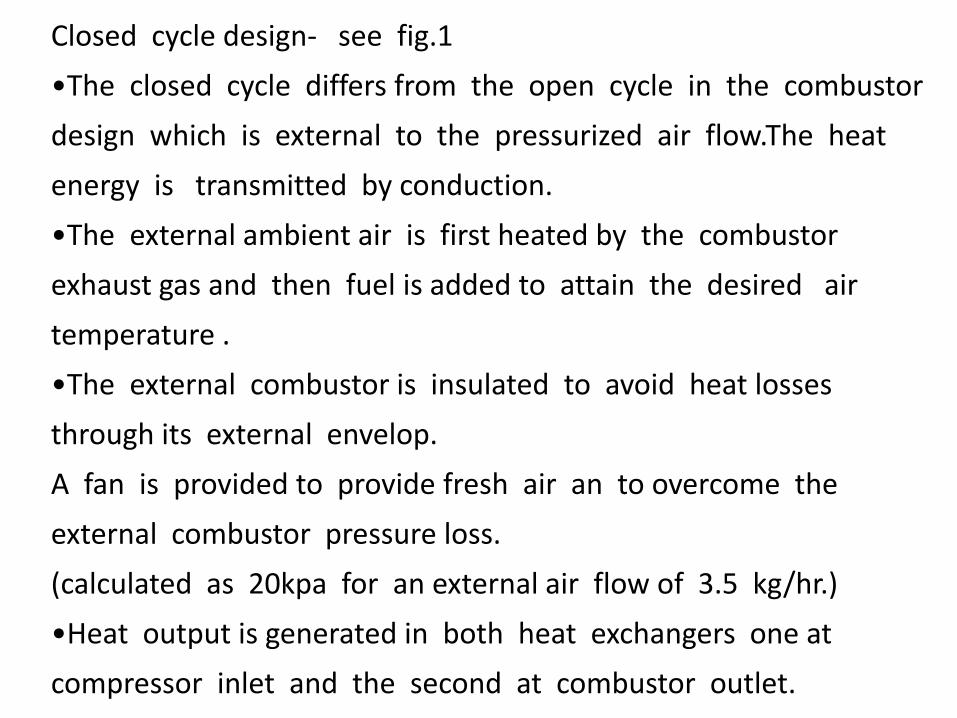
Closed cycle design- see fig.1
•The closed cycle differs from the open cycle in the combustor
design which is external to the pressurized air flow.The heat
energy is transmitted by conduction.
•The external ambient air is first heated by the combustor
exhaust gas and then fuel is added to attain the desired air
temperature .
•The external combustor is insulated to avoid heat losses
through its external envelop.
A fan is provided to provide fresh air an to overcome the
external combustor pressure loss.
(calculated as 20kpa for an external air flow of 3.5 kg/hr.)
•Heat output is generated in both heat exchangers one at
compressor inlet and the second at combustor outlet.

3.1 -The TG-40 micro turbine performance is evaluated when
modifying it to a closed cycle design and boosting its inlet air pressure
to 1000 kpa. The results are presented in TABLE A as:
Thermal power -472kw, Thermal efficiency-37.15%
Unfortunately at a speed of 80000 rpm the existing high speed
alternator technology is limited to 40kw at 80000 rpm (Calnetix),
100kw at 70000 rpm (ABB) and 200kw at 60000 rpm (Capstone).The
limiting barrier is the stress at the permanent magnet rotor.

TABLE A—THEMODYNAMIC OF TG-500 CYCLE - INLET PRESSURE BOOSTED TO 1000 KPA
POWER=472KW at 80000 rpm
W T P WRstd
Station kg/s K kPa kg/s PWSD = 472 kW
amb 1 3.038 288.00 1000.130 PSFC = 0.1948 kg/(kW*h) 2 3.038 288.00 980.127 0.314 Heat Rate= 9690.6 kJ/(kW*h) 3 3.038 421.67 2940.382 0.127 ThermEff= 0.3715
31 3.038 421.67 2940.382 WF = 0.02505 kg/s 35 2.856 979.02 2896.276 P35/P3 = 0.98500
4 2.881 1310.00 2780.425 0.225 P7/P6 = 0.98000
41 3.063 1291.13 2780.425 0.237 s NOx = 2.44674
49 3.063 1051.43 1030.849 incidence= 0.00000 ° 5 3.063 1051.43 1030.849 0.577 XM8 = 2.201E-4
6 3.063 1051.43 1020.541 A8 = 4.5843 m² 7 3.063 518.34 1000.130
8 3.063 518.34 1000.130 0.417 P8/Ps8 = 1.00000
Bleed 0.000 421.67 2940.376WBld/W2 = 0.00000
Efficiencies: isentrpolytr RNI P/P W_NGV/W2 = 0.06000
Compressor 0.7900 0.8194 9.679 3.000 WCL/W2 = 0.00000
Burner 0.9600 0.960 Loading = 100.00 % Turbine 0.8700 0.8555 4.745 2.697 e45 th = 0.86853
Heat Exch. 0.8800 Generator 0.96 Transmission 0.96
PW_gen = 425 Kw- Spool mechEff 0.9950 Nom Spd 80000 rpm P6/P5 = 0.9900
hum [%] war0 FHV Fuel 0.0 0.00000 49.736 Natural Gas

4. Competitive Cost closed cycle design.- boosting to 750 kpa
Thermal efficiency-37.7% Thermal Power-522kw Design Speed-50Krpm-see Table B
a. Application of the following large gas turbine architecture –
•Synchronic alternator generating 50/60 HZ turning at 1500/1800
rpm.
•Planetary transmission 33:1 for 1500 , 27:1 for1800 rpm
Electric starter driving transmission exit shaft.

TABLE B—THEMODYNAMIC OF TG-500 CYCLE - INLET PRESSURE BOOSTED TO 1000 KPA
POWER=522 kW at 50000 rpm
W T P WRstd
Station kg/s K kPa kg/s PWSD = 522.4 kW
amb 300.00 750.000 1 3.555 300.00 750.000 PSFC = 0.1921 kg/(kW*h) 2 3.555 300.00 735.000 0.500 ThermEff= 0.37673
24 3.555 300.01 735.073 0.500 Heat Rate= 9556.0 kJ/(kW*h) 25 3.555 300.01 735.073 0.500 P2/P1 = 0.9800
3 3.555 437.24 2205.220 0.201 P25/P24 = 1.0000
31 3.555 437.24 2205.220 P3/P2 = 3.00
35 3.341 963.76 2172.142 0.285 P35/P3 = 0.98500
4 3.369 1290.00 2150.421 0.337 WF = 0.02788 kg/s 41 3.582 1271.31 2150.421 0.356 Loading = 100.00 % 42 3.582 1156.03 1360.771 s NOx = 2.01613
43 3.582 1156.03 1360.771
44 3.582 1156.03 1360.771
45 3.582 1156.03 1360.771 0.536 P45/P43 = 1.00000
49 3.582 1032.61 796.543 5 3.582 1032.61 796.543 0.865 6 3.582 1032.61 780.612 P6/P5 = 0.98000
8 3.582 527.83 765.000 0.644 P7/P6 = 0.98000
Efficiencies: isentr polytr RNI P/P A8 = 0.00933 m² Compressor 0.8000 0.8279 6.916 3.000 Burner 0.9900 0.990 HP Turbine 0.8700 0.8635 3.735 1.580 LP Turbine 0.8700 0.8624 2.632 1.708 eta t-s = 0.78767
Heat Exch .8800
Generator 0.96 Transmission 0.96
PW_gen = 483 Kw-------------------------------------------- HP Spool mechEff0.9950 NomSpd 50000 rpm LP Spool mechEff1.0000 NomSpd 50000 rpm PT Spool Nom Spd 50000 rpm hum [%] war0 FHV Fuel 0.0 0.00000 49.736 Natural Gas

5. SUMMARY
A closed cycle design of micro turbines is presented as a cost
effective solution which is competitive to gas piston engines cost
and performance for the CHP markets.
This design allows to use efficiently the same core engine for
variable power.
This design will result in a total energy (Power and Heat)
efficiency of 85%-92%.