Embed Size (px)
Citation preview

Thank you for purchasing the CJ-500.
• To ensure correct and safe usage with a full understanding of thisproduct's performance, please be sure to read through this manualcompletely and store it in a safe location.
• Unauthorized copying or transferral, in whole or in part, of this manualis prohibited.
• The contents of this operation manual and the specifications of thisproduct are subject to change without notice.
• The operation manual and the product have been prepared and tested asmuch as possible. If you find any misprint or error, please inform us.
• Roland DG Corp. assumes no responsibility for any direct or indirectloss or damage which may occur through use of this product, regardlessof any failure to perform on the part of this product.
USER'S MANUAL
C J - 5 0 0C J - 5 0 0C J - 5 0 0C J - 5 0 0C J - 5 0 0
For the USA
FEDERAL COMMUNICATIONS COMMISSIONRADIO FREQUENCY INTERFERENCE
STATEMENT
This equipment has been tested and found to comply with thelimits for a Class A digital device, pursuant to Part 15 of theFCC Rules.These limits are designed to provide reasonable protectionagainst harmful interference when the equipment is operatedin a commercial environment.This equipment generates, uses, and can radiate radiofrequency energy and, if not installed and used in accordancewith the instruction manual, may cause harmful interferenceto radio communications.Operation of this equipment in a residential area is likely tocause harmful interference in which case the user will berequired to correct the interference at his own expense.
Unauthorized changes or modification to this system can voidthe users authority to operate this equipment.
The I/O cables between this equipment and the computingdevice must be shielded.
NOTICEGrounding Instructions
Do not modify the plug provided - if it will not fit the outlet,have the proper outlet installed by a qualified electrician.
Check with qualified electrician or service personnel if thegrounding instructions are not completely understood, or if indoubt as to whether the tool is properly grounded.
Use only 3-wire extension cords that have 3-pronggrounding plugs and 3-pole receptacles that accept the tool’splug.
Repair or replace damaged or worn out cord immediately.
For Canada
CLASS A NOTICE
This Class A digital apparatus meets all requirements of theCanadian Interference-Causing Equipment Regulations.
CLASSE A AVIS
Cet appareil numérique de la classe A respecte toutes lesexigences du Règlement sur le matériel brouilleur duCanada.
Operating Instructions
KEEP WORK AREA CLEAN. Cluttered areas and benchesinvite accidents.
DON’T USE IN DANGEROUS ENVIRONMENT. Don’tuse power tools in damp or wet locations, or expose them torain. Keep work area well lighted.
DISCONNECT TOOLS before servicing; when changingaccessories, such as blades, bits, cutters, etc.
REDUCE THE RISK OF UNINTENTIONAL STARTING.Make sure the switch is in off position before plugging in.
USE RECOMMENDED ACCESSORIES. Consult theowner’s manual for recommended accessories. The use ofimproper accessories may cause risk of injury.
NEVER LEAVE TOOL RUNNING UNATTENDED.TURN POWER OFF. Don’t leave tool until it comes to acomplete stop.
1
Copyright © 1999 ROLAND DG CORPORATION
Windows® is a registered trademark or trademark of Microsoft® Corporation in the United States and/or other countries.IBM is a registered trademark of International Business Machines Corporation.Macintosh is a registered trademark or trademark of Apple Computer, Inc. in the USA and other countries.Other company names and product names are trademarks or registered trademarks of their respective holders.COLORCHOICE® is a registered in the U.S. Patent Office.
Table of Contents
To Ensure Safe Use .......................................2
About the Labels Affixed to the Unit ......4
Pour utiliser en toute sécurité .........6
À propos des étiquettes collées sur l'appareil ....9
Unpacking the CAMMJET..................................... 11
1 Checking Accessories ..........................................11
2 Setting Up and Connection ..................................12
3 Attaching the Drain Bottle .................................... 14
4 Installing Ink Cartridges ........................................ 16
5 Power up ................................................................. 18
Part Names .................................................................19
Front View .....................................................................19
Rear View .....................................................................20
Inside the Front Cover ................................................20
Operation Panel ...........................................................21
Five modes .................................................................22
Setup for Printing .................................................23
1 Loading the Material ...............................................23
2 Test Printing .............................................................27
3 Setting the Printing Mode and Printing Direction ....... 28
Setup for Cutting ...................................................29
1 Loading the Material ...............................................29
2 Installing a Blade .....................................................33
3 Test Cutting ..............................................................34
Setup for Printing and Cutting ..................36
Downloading Printing/Cutting Data ..........37
Remov ing the Materia l ..................................... 39
Remove the Material from the machine ...................39
Cut the material from the roll .....................................39
When Operations Are Finished ................41
Maintenance ..............................................................42
Replacing the Ink Cartridges .....................................42
Check how much ink remains ....................................44
Cleaning the Printing Heads ......................................44
Changing the Type of Ink ...........................................46
Replacing the Cutter Blade ........................................47
How to Replace the Separating Knife ......................48
When the Product Needs Cleaning ..........................49
When Not in Use for a Prolonged Period... .............50
When Moving the Unit... .............................................51
User's Reference ...................................................53
Setting the start point....................................................... 53
Adjusting the Printing and Cutting Positions ...........54
Remove the Printed Material,
then Reload the Material and Perform Cutting .................56
Making Corrections for Printing .................................59
Aligning the Printing Length and Cutting Length ............61
Performing Overprinting .............................................63
Setting the Page Margins ...........................................64
About the Prefeed ([PREFEED]) Function ..............65
To Perform Long Printing/Cutting .............................66
Adjusting the Height of the Printing Head ................67
Materials ........................................................................68
About Blade Life ..........................................................70
About the Printing/Cutting Area .................................71
Description of Keys ............................................72
Description of Menu Items ...........................74
Description of Menu..................................................... 74
Display Menu Flowchart ............................................. 77
What to Do If... .........................................................81
Error Messages ......................................................86
Specifications ..........................................................88
2
To Ensure Safe Use
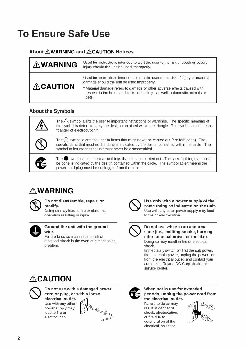
Used for instructions intended to alert the user to the risk of death or severeinjury should the unit be used improperly.
About and Notices
Used for instructions intended to alert the user to the risk of injury or materialdamage should the unit be used improperly.
* Material damage refers to damage or other adverse effects caused withrespect to the home and all its furnishings, as well to domestic animals orpets.
About the Symbols
The symbol alerts the user to important instructions or warnings. The specific meaning ofthe symbol is determined by the design contained within the triangle. The symbol at left means"danger of electrocution."
The symbol alerts the user to items that must never be carried out (are forbidden). Thespecific thing that must not be done is indicated by the design contained within the circle. Thesymbol at left means the unit must never be disassembled.
The symbol alerts the user to things that must be carried out. The specific thing that mustbe done is indicated by the design contained within the circle. The symbol at left means thepower-cord plug must be unplugged from the outlet.
Do not disassemble, repair, ormodify.Doing so may lead to fire or abnormaloperation resulting in injury.
Ground the unit with the groundwire.Failure to do so may result in risk ofelectrical shock in the even of a mechanicalproblem.
Use only with a power supply of thesame rating as indicated on the unit.Use with any other power supply may leadto fire or electrocution.
Do not use with a damaged powercord or plug, or with a looseelectrical outlet.Use with any otherpower supply maylead to fire orelectrocution.
Do not use while in an abnormalstate (i.e., emitting smoke, burningodor, unusual noise, or the like).Doing so may result in fire or electricalshock.Immediately switch off first the sub power,then the main power, unplug the power cordfrom the electrical outlet, and contact yourauthorized Roland DG Corp. dealer orservice center.
When not in use for extendedperiods, unplug the power cord fromthe electrical outlet.Failure to do so mayresult in danger ofshock, electrocution,or fire due todeterioration of theelectrical insulation.
3
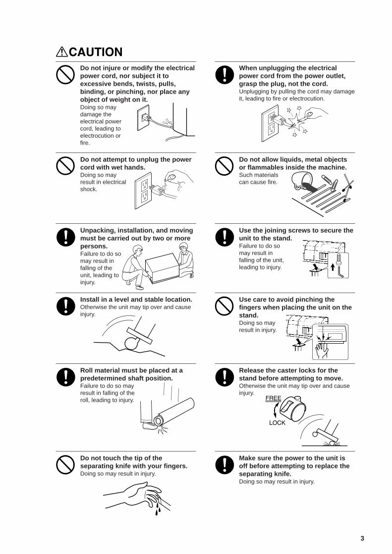
Do not injure or modify the electricalpower cord, nor subject it toexcessive bends, twists, pulls,binding, or pinching, nor place anyobject of weight on it.Doing so maydamage theelectrical powercord, leading toelectrocution orfire.
When unplugging the electricalpower cord from the power outlet,grasp the plug, not the cord.Unplugging by pulling the cord may damageit, leading to fire or electrocution.
Do not attempt to unplug the powercord with wet hands.Doing so mayresult in electricalshock.
Do not allow liquids, metal objectsor flammables inside the machine.Such materialscan cause fire.
Unpacking, installation, and movingmust be carried out by two or morepersons.Failure to do somay result infalling of theunit, leading toinjury.
Use the joining screws to secure theunit to the stand.Failure to do somay result infalling of the unit,leading to injury.
Install in a level and stable location.Otherwise the unit may tip over and causeinjury.
Use care to avoid pinching thefingers when placing the unit on thestand.Doing so mayresult in injury.
Roll material must be placed at apredetermined shaft position.Failure to do so mayresult in falling of theroll, leading to injury.
Release the caster locks for thestand before attempting to move.Otherwise the unit may tip over and causeinjury.
Do not touch the tip of theseparating knife with your fingers.Doing so may result in injury.
Make sure the power to the unit isoff before attempting to replace theseparating knife.Doing so may result in injury.

4
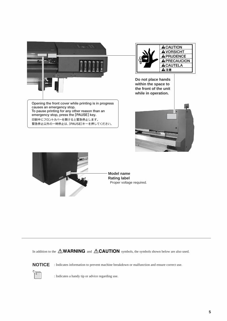
Do not place hands within the spaceto the front of the unit while inoperation.Doing so may result in injury.
If ink contacts the eyes, flushimmediately with water.
Store ink cartridges out of the reachof children.
Do not dismantle the cartridge.Keep out of reach of children.Do not store the cartridge in high or freezing temperatures.
About the Labels Affixed to the UnitThese labels are affixed to the body of this product.The following figure describes the location andcontent of these messages.
Ink cartridge
5
: Indicates information to prevent machine breakdown or malfunction and ensure correct use.
: Indicates a handy tip or advice regarding use.
In addition to the and symbols, the symbols shown below are also used.
NOTICE
Do not place handswithin the space tothe front of the unitwhile in operation.
Model nameRating label Proper voltage required.

6
Utilisé pour avertir l'utilisateur d'un risque de décès ou de blessure grave encas de mauvaise utilisation de l'appareil.
Avis sur les avertissements
Utilisé pour avertir l'utilisateur d'un risque de blessure ou de dommagematériel en cas de mauvaise utilisation de l'appareil.
* Par dommage matériel, il est entendu dommage ou tout autre effetindésirable sur la maison, tous les meubles et même les animauxdomestiques.
Ne pas démonter, réparer oumodifier.Le non-respect de cette consigne pourraitcauser un incendie ou provoquer desopérations anormales entraînant desblessures.
Mettre l'appareil à la masse avec uneprise de terre.Le non-respect de cette consigne pourraitentraîner des décharges électriques encas de problème mécanique.
Utiliser seulement avec unealimentation de mêmescaractéristiques électriques quecelles indiquées sur l'appareil.Une négligence à ce niveau pourraitprovoquer un incendie ou uneélectrocution.
Ne pas utiliser si l'appareil est dansun état anormal (c'est-à-dire s'il y aémission de fumée, odeur de brûlé,bruit inhabituel etc.).Le non-respect de cette consigne pourraitprovoquer un incendie ou des déchargesélectriques.Couper immédiatement l'alimentationsecondaire et ensuite l'alimentationprincipale. Débranchez le fil électrique etcontacter votre revendeur ou votre centrede service de la société Roland DGautorisé.
À propos des symboles
Le symbole attire l'attention de l'utilisateur sur les instructions importantes ou lesavertissements. Le sens précis du symbole est déterminé par le dessin à l'intérieur du triangle.Le symbole à gauche signifie "danger d'électrocution".
Le symbole avertit l'utilisateur de ce qu'il ne doit pas faire, ce qui est interdit. La chosespécifique à ne pas faire est indiquée par le dessin à l'intérieur du cercle. Le symbole àgauche signifie que l'appareil ne doit jamais être démonté.
Le symbole prévient l'utilisateur sur ce qu'il doit faire. La chose spécifique à faire estindiquée par le dessin à l'intérieur du cercle. Le symbole à gauche signifie que le fil électriquedoit être débranché de la prise.
Pour utiliser en toute sécurité
7
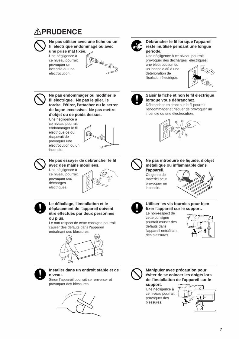
Ne pas endommager ou modifier lefil électrique. Ne pas le plier, letordre, l'étirer, l'attacher ou le serrerde façon excessive. Ne pas mettred'objet ou de poids dessus.Une négligence àce niveau pourraitendommager le filélectrique ce quirisquerait deprovoquer uneélectrocution ou unincendie.
Saisir la fiche et non le fil électriquelorsque vous débranchez.Débrancher en tirant sur le fil pourraitl'endommager et risquer de provoquer unincendie ou une électrocution.
Ne pas essayer de débrancher le filavec des mains mouillées.Une négligence àce niveau pourraitprovoquer desdéchargesélectriques.
Ne pas introduire de liquide, d'objetmétallique ou inflammable dansl'appareil.Ce genre dematériel peutprovoquer unincendie.
Le déballage, l'installation et ledéplacement de l'appareil doiventêtre effectués par deux personnesou plus.Le non-respect de cette consigne pourraitcauser des défauts dans l'appareilentraînant des blessures.
Utiliser les vis fournies pour bienfixer l'appareil sur le support.Le non-respect decette consignepourrait causer desdéfauts dansl'appareil entraînantdes blessures.
Installer dans un endroit stable et deniveau.Sinon l'appareil pourrait se renverser etprovoquer des blessures.
Manipuler avec précaution pouréviter de se coincer les doigts lorsde l'installation de l'appareil sur lesupport.Une négligence àce niveau pourraitprovoquer desblessures.
Ne pas utiliser avec une fiche ou unfil électrique endommagé ou avecune prise mal fixée.Une négligence àce niveau pourraitprovoquer unincendie ou uneélectrocution.
Débrancher le fil lorsque l'appareilreste inutilisé pendant une longuepériode.Une négligence à ce niveau pourraitprovoquer des décharges électriques,une électrocution ouun incendie dû à unedétérioration del'isolation électrique.
8
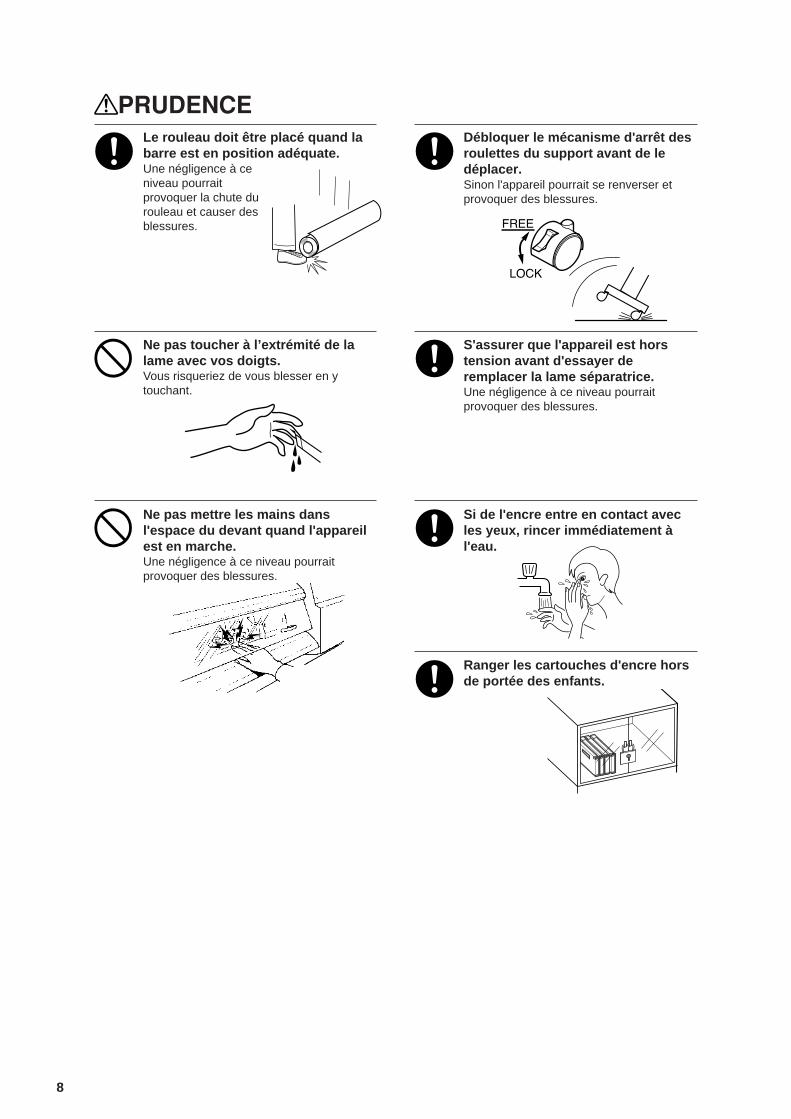
Le rouleau doit être placé quand labarre est en position adéquate.Une négligence à ceniveau pourraitprovoquer la chute durouleau et causer desblessures.
Débloquer le mécanisme d'arrêt desroulettes du support avant de ledéplacer.Sinon l'appareil pourrait se renverser etprovoquer des blessures.
Ne pas toucher à l’extrémité de lalame avec vos doigts.Vous risqueriez de vous blesser en ytouchant.
S'assurer que l'appareil est horstension avant d'essayer deremplacer la lame séparatrice.Une négligence à ce niveau pourraitprovoquer des blessures.
Ne pas mettre les mains dansl'espace du devant quand l'appareilest en marche.Une négligence à ce niveau pourraitprovoquer des blessures.
Si de l'encre entre en contact avecles yeux, rincer immédiatement àl'eau.
Ranger les cartouches d'encre horsde portée des enfants.

9
À propos des étiquettes collées sur l'appareilCes étiquettes sont collées à l'extérieur de l'appareil.Les dessins suivants indiquent l'endroit et le contenu des messages.
Ne pas démonter la cartouche.Conserver hors de la portée des enfants.Ne pas emmagasiner á das températures hautes oubasses.
la cartouche d'encre
Ouvrir la plaque avant pendant l’impressionprovoque un arrêt d’urgence.Appuyer sur “PAUSE” si, pour toute autreraison qu’une urgence, vous désirezsuspendre momentanément l’impression.
Ne pas mettre lesmains dans l'espacedevant l'élémentquand celui-ci esten marche.
Nom du modèleÉtiquette des caractéristiques électriques Utiliser l'alimentation appropriée

10
MEMO
11
Unpacking the CAMMJET
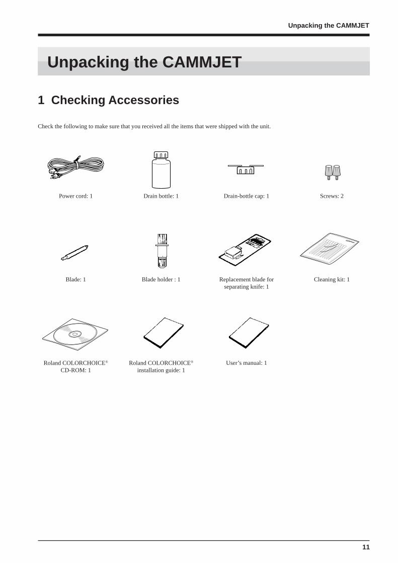
1 Checking Accessories
Check the following to make sure that you received all the items that were shipped with the unit.
Power cord: 1 Drain bottle: 1 Drain-bottle cap: 1 Screws: 2
Roland COLORCHOICE®
installation guide: 1Roland COLORCHOICE®
CD-ROM: 1User’s manual: 1
Replacement blade forseparating knife: 1
Blade: 1 Blade holder : 1 Cleaning kit: 1
Unpacking the CAMMJET

12
Unpacking the CAMMJET
2 Setting Up and Connection
For an explanation of how to assemble the unit and the stand (PNS-501), refer to the “ASSEMBLY INSTRUCTIONS” included with thestand.When using the unit while mounted on a stand, be sure to ensure a sufficient amount of installation space for the unit. The requiredinstallation spaces for this model are listed below.
2700 mm (106-5/16 in.) wide, 900 mm (35-7/16 in.) depth, and 1500 mm (59-1/16 in.) high
Be sure to install the drain bottle before switching on the power.
Never install the unit in any of the following situations, as it could result in breakdown or faulty operation:Places where the installation surface is unstable or not level.Places with excessive electrical noise.Places with excessive humidity or dust.Places with poor ventilation, because the CJ-500 generates considerable heat during operation.Places with excessive vibration.Places exposed to strong illumination or direct sunlight.
Unpacking, installation, and movingmust be carried out by two or morepersons.Failure to do somay result infalling of theunit, leading toinjury.
Install in a level and stable location.Otherwise the unit may tip over and causeinjury.
NOTICE
Never step or stand on the stand legs, as doing so may damage them.
Do not place objects on the unit, as doing so may result in breakdown.
Setting Up
13
Unpacking the CAMMJET
Use only with a power supply of thesame rating as indicated on the unit.Use with any other power supply may leadto fire or electrocution.
Ground the unit with the groundwire.Failure to do so may result in risk ofelectrical shock in the even of a mechanicalproblem
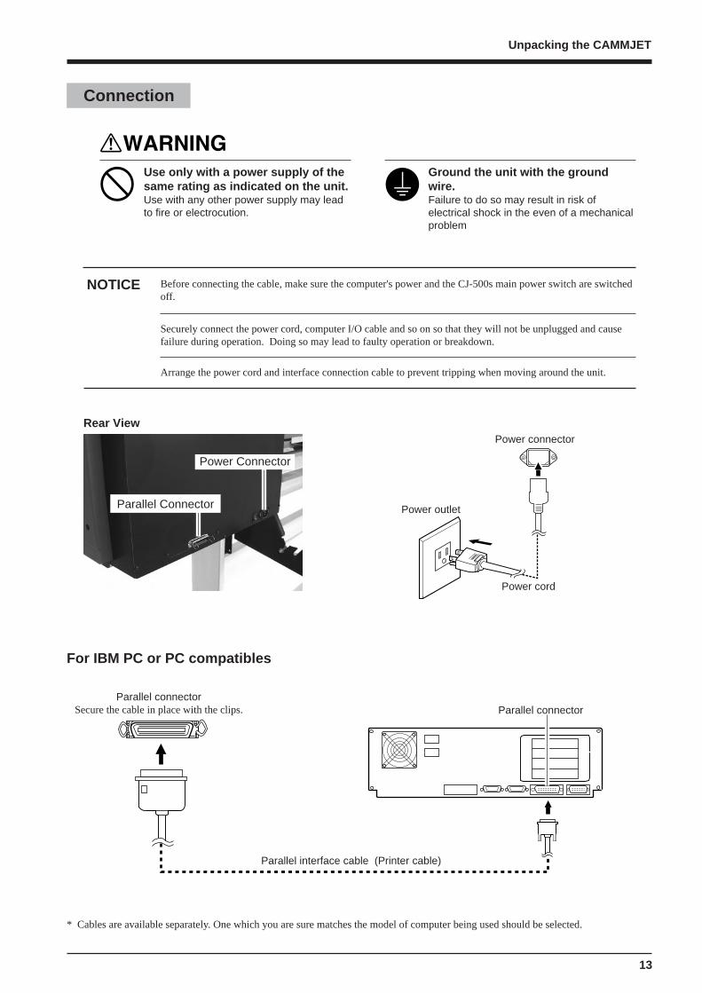
Before connecting the cable, make sure the computer's power and the CJ-500s main power switch are switchedoff.
Securely connect the power cord, computer I/O cable and so on so that they will not be unplugged and causefailure during operation. Doing so may lead to faulty operation or breakdown.
Arrange the power cord and interface connection cable to prevent tripping when moving around the unit.
NOTICE
Power connector
Power outlet
Power cord
* Cables are available separately. One which you are sure matches the model of computer being used should be selected.
For IBM PC or PC compatibles
Parallel connectorSecure the cable in place with the clips.
Parallel interface cable (Printer cable)
Parallel connector
Connection
Rear View
Power Connector
Parallel Connector
14
Unpacking the CAMMJET
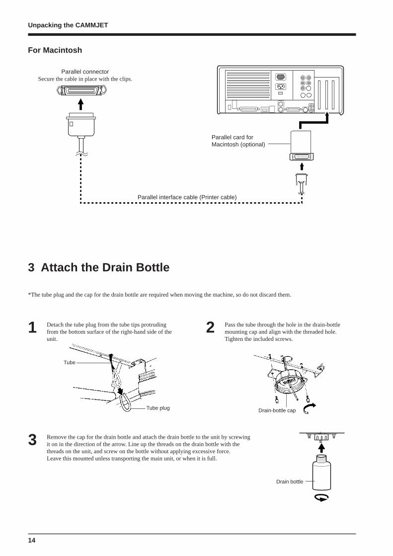
For Macintosh
Parallel interface cable (Printer cable)
Parallel connectorSecure the cable in place with the clips.
Parallel card forMacintosh (optional)
*The tube plug and the cap for the drain bottle are required when moving the machine, so do not discard them.
1 Detach the tube plug from the tube tips protrudingfrom the bottom surface of the right-hand side of theunit.
Drain bottle
3 Remove the cap for the drain bottle and attach the drain bottle to the unit by screwingit on in the direction of the arrow. Line up the threads on the drain bottle with thethreads on the unit, and screw on the bottle without applying excessive force.Leave this mounted unless transporting the main unit, or when it is full.
2 Pass the tube through the hole in the drain-bottlemounting cap and align with the threaded hole.Tighten the included screws.
Drain-bottle cap
3 Attach the Drain Bottle
Tube
Tube plug
15
Unpacking the CAMMJET
The POWER LED goes out
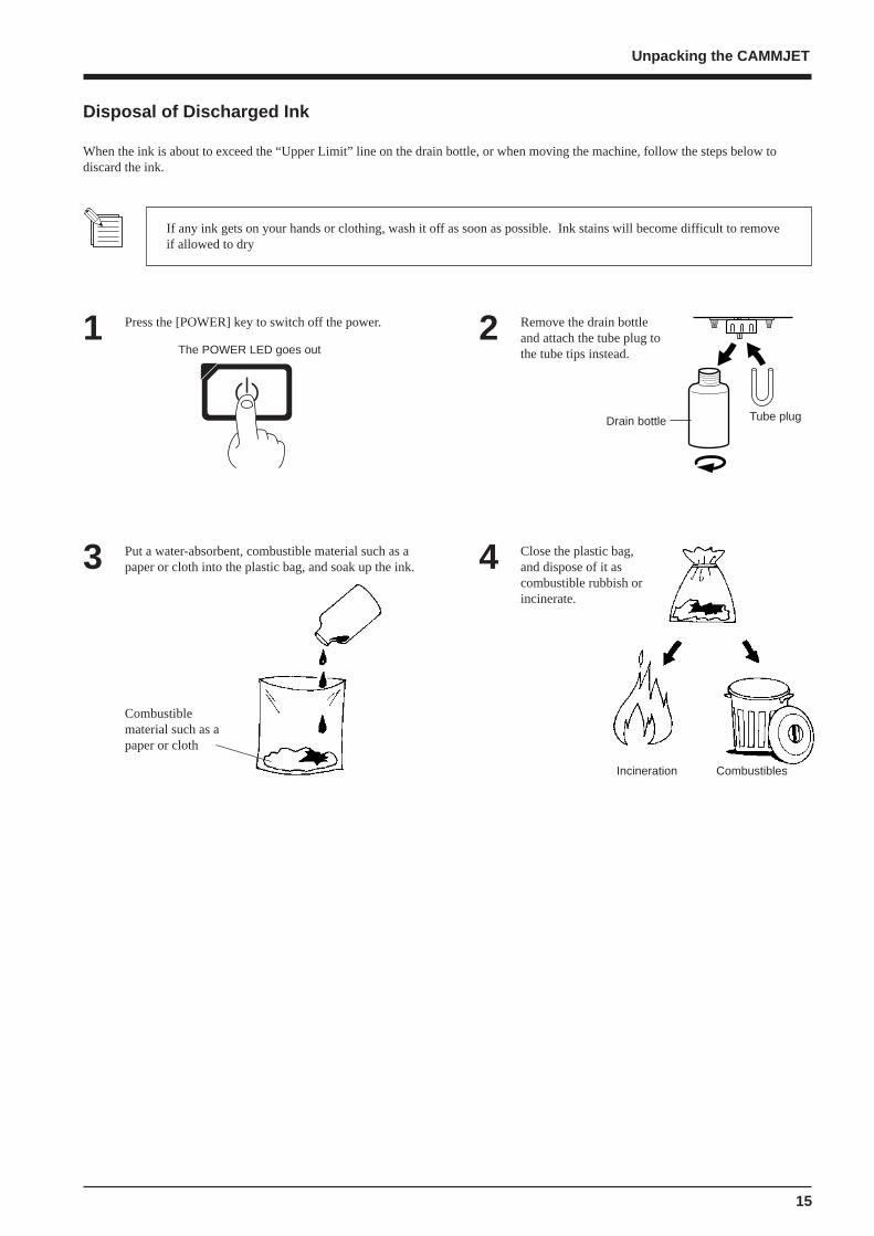
If any ink gets on your hands or clothing, wash it off as soon as possible. Ink stains will become difficult to removeif allowed to dry
When the ink is about to exceed the “Upper Limit” line on the drain bottle, or when moving the machine, follow the steps below todiscard the ink.
Press the [POWER] key to switch off the power.1 Remove the drain bottleand attach the tube plug tothe tube tips instead.
2
Tube plugDrain bottle
4Put a water-absorbent, combustible material such as apaper or cloth into the plastic bag, and soak up the ink.3 Close the plastic bag,
and dispose of it ascombustible rubbish orincinerate.
Combustiblematerial such as apaper or cloth
Incineration Combustibles
Disposal of Discharged Ink
16
Unpacking the CAMMJET
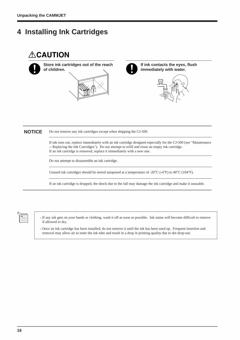
Store ink cartridges out of the reachof children.
If ink contacts the eyes, flushimmediately with water.
Do not remove any ink cartridges except when shipping the CJ-500.
If ink runs out, replace immediately with an ink cartridge designed especially for the CJ-500 (see "Maintenance-- Replacing the Ink Cartridges"). Do not attempt to refill and reuse an empty ink cartridge.If an ink cartridge is removed, replace it immediately with a new one.
NOTICE
Do not attempt to disassemble an ink cartridge.
Unused ink cartridges should be stored unopened at a temperature of -20°C (-4°F) to 40°C (104°F).
If an ink cartridge is dropped, the shock due to the fall may damage the ink cartridge and make it unusable.
- If any ink gets on your hands or clothing, wash it off as soon as possible. Ink stains will become difficult to removeif allowed to dry.
- Once an ink cartridge has been installed, do not remove it until the ink has been used up. Frequent insertion andremoval may allow air to enter the ink tube and result in a drop in printing quality due to dot drop-out.
4 Installing Ink Cartridges
17
Unpacking the CAMMJET
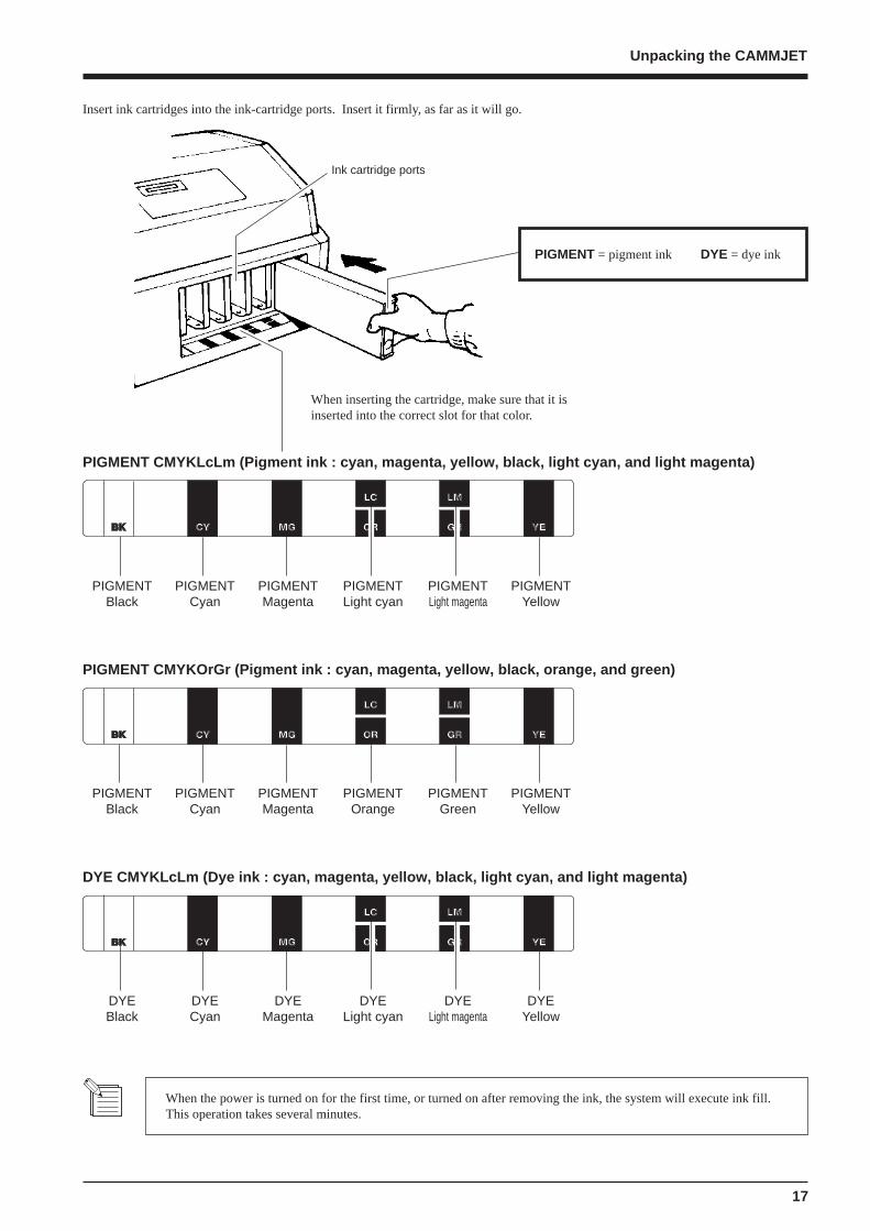
Insert ink cartridges into the ink-cartridge ports. Insert it firmly, as far as it will go.
Ink cartridge ports
When inserting the cartridge, make sure that it isinserted into the correct slot for that color.
PIGMENT CMYKLcLm (Pigment ink : cyan, magenta, yellow, black, light cyan, and light magenta)
PIGMENTBlack
PIGMENTCyan
PIGMENTMagenta
PIGMENTLight cyan
PIGMENTLight magenta
PIGMENTYellow
PIGMENT CMYKOrGr (Pigment ink : cyan, magenta, yellow, black, orange, and green)
PIGMENTBlack
PIGMENTCyan
PIGMENTMagenta
PIGMENTOrange
PIGMENTGreen
PIGMENTYellow
PIGMENT = pigment ink DYE = dye ink
When the power is turned on for the first time, or turned on after removing the ink, the system will execute ink fill.This operation takes several minutes.
DYE CMYKLcLm (Dye ink : cyan, magenta, yellow, black, light cyan, and light magenta)
DYEBlack
DYECyan
DYEMagenta
DYELight cyan
DYELight magenta
DYEYellow

18
Unpacking the CAMMJET
The POWER LED lights up
When the power is turned on for the firsttime, or turned on after removing the ink
Be sure to mount the drain bottle before turning on the power. Refer to section "3 Attach the Drain Bottle".
When using for the first time turn on the main power switch on therear of the unit.
* Leave the main power switch on, and turn the power off and on indaily use with the sub power switch on the front of the machine.
1
Press the [POWER] key on the operation panel.2
Roland CJ-500 Ver.1.00
Roland CJ-500UNKNOWN INK TYPE
SELECT INK TYPEPIG.CMYKLcLm
INSTALL DRAIN TANK
NOW FILLING INK
Use the [ ] [ ] key to select the installed ink type and press the [ENTER] key.
No ink is filled.
Attach the drain tank, and press the [ENTER] key.
The system will execute ink fill.This operation takes several minutes.
PIG. CMYKLcLm/PIG. CMYKOrGr/DYE CMYKLcLm
The POWER LED lights up
5 Power up
19
Part Names
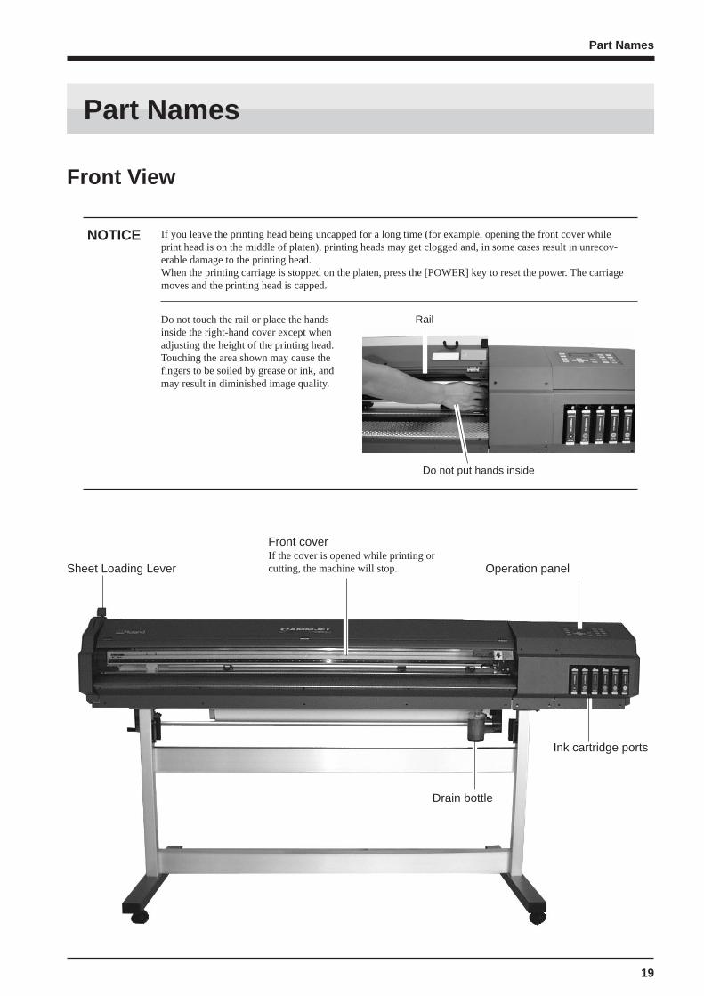
NOTICE If you leave the printing head being uncapped for a long time (for example, opening the front cover whileprint head is on the middle of platen), printing heads may get clogged and, in some cases result in unrecov-erable damage to the printing head.When the printing carriage is stopped on the platen, press the [POWER] key to reset the power. The carriagemoves and the printing head is capped.
Front View
Sheet Loading Lever
Front coverIf the cover is opened while printing orcutting, the machine will stop. Operation panel
Ink cartridge ports
Drain bottle
Do not touch the rail or place the handsinside the right-hand cover except whenadjusting the height of the printing head.Touching the area shown may cause thefingers to be soiled by grease or ink, andmay result in diminished image quality.
Do not put hands inside
Part Names
Rail
20
Part Names
Inside the Front Cover
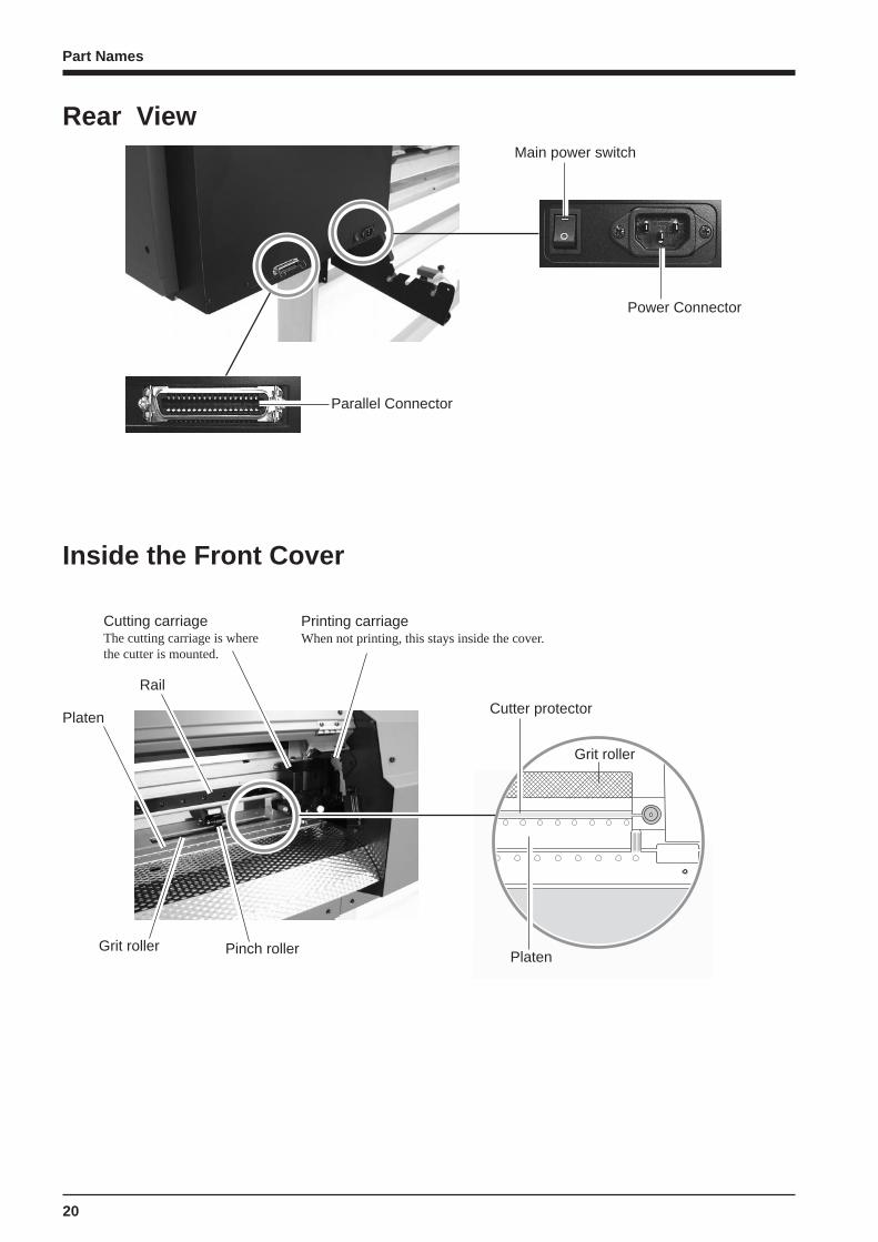
Parallel Connector
Main power switch
Rear View
Power Connector
Pinch rollerGrit roller
Platen
Printing carriageWhen not printing, this stays inside the cover.
Platen
Grit roller
Cutter protector
Cutting carriageThe cutting carriage is wherethe cutter is mounted.
Rail

21
Part Names
Operation PanelFor more information about the keys, take a look at "Description of Keys".
DisplayThis show the various settingmenus, and messages.
BUSY LEDThis flashes while data is beingreceived from the host computer.
[ENTER] key
[BASE POINT] key
BASE POINT LED
ALIGN POINT LED
[ALIGN POINT] key
SETUP LED
[SETUP] key
PAUSE LED
[PAUSE] key
[SHEET CUT] key
POWER LED
[POWER] key
[TEST PRINT] key
[PRINT CONFIG] key
[CUT CONFIG] key
[CLEANING] key
[TEST CUT] key
[TOOL UP/DOWN] key
Arrow keys( [ ] [ ] [ ] [ ] )
[MENU] key
22
Five Modes
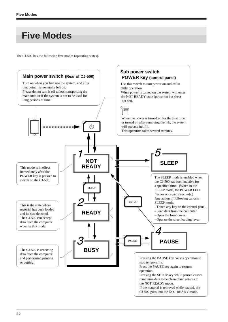
Main power switch (Rear of CJ-500)
Turn on when you first use the system, and after that point it is generally left on. Please do not turn it off unless transporting the main unit, or if the system is not to be used for long periods of time.
Sub power switch POWER key (control panel)
NOTREADY
READY
BUSY
SLEEP
PAUSE
This mode is in effect immediately after the POWER key is pressed to switch on the CJ-500.
This is the state where material has been loadedand its size detected.The CJ-500 can accept data from the computer when in this mode.
The CJ-500 is receiving data from the computerand performing printing or cutting
The SLEEP mode is enabled when the CJ-500 has been inactive for a specified time. (When in the SLEEP mode, the POWER LED flashes once per 2 seconds.)Any action of following cancels SLEEP mode.- Touch any key on the control panel.- Send data from the computer.- Open the front cover.- Operate the sheet loading lever.
Pressing the PAUSE key causes operation to stop temporarily.Press the PAUSE key again to resume operation.Pressing the SETUP key while paused causes remaining data to be cleared and returns to the NOT READY mode.If the material is removed while paused, the CJ-500 goes into the NOT READY mode.
Use this switch to turn power on and off in daily operation. When power is turned on the system will enterthe NOT READY state (power on but sheet not set).
When the power is turned on for the first time, or turned on after removing the ink, the system will execute ink fill. This operation takes several minutes.
The CJ-500 has the following five modes (operating states).
Five Modes

23
Roll material must be placed at apredetermined shaft position.Failure to do so mayresult in dropping theroll, leading to injury.
Acceptable material widths
90 mm to 1371 mm (3.5 in. to 54 in.)
* N O T E : when loading material with a widthof 90 mm to 430 mm (3.5 in. to 17 in.), set the[EDGE SENSE] menu item to [DISABLE].
Pass the stoppers onto both ends of the shaft.(The shafts (2 pieces), stoppers (2 pieces), and screws(2 pieces) are included with the stand.)
* When passing the shaft through the stopper,be sure to loosen the screws on the stopperfirst.
1
Loading Roll Material
Align the media flange with the roll sheet edges, matching the roll sheet center ID.(The media flange is included with the stand.)2
1 Loading the Material
Stopper
Tighten loosely with the screws.
Shaft
Media flange
Media flange
Media flange
50.8 mm(2 in.)
76.2 mm(3 in.)
Setup for Printing
Setup for Printing
24
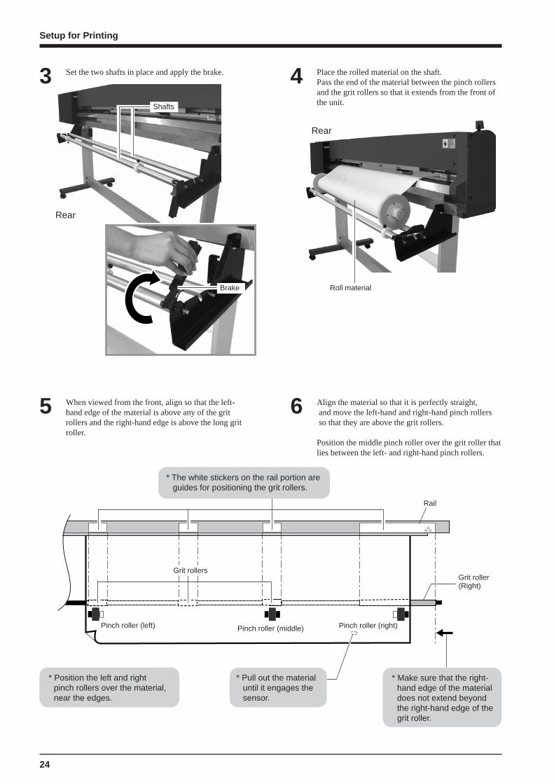
When viewed from the front, align so that the left-hand edge of the material is above any of the gritrollers and the right-hand edge is above the long gritroller.
5
Set the two shafts in place and apply the brake.3 Place the rolled material on the shaft.Pass the end of the material between the pinch rollersand the grit rollers so that it extends from the front ofthe unit.
4
Align the material so that it is perfectly straight, and move the left-hand and right-hand pinch rollers so that they are above the grit rollers.
Position the middle pinch roller over the grit roller thatlies between the left- and right-hand pinch rollers.
6
Rear
Roll material
* The white stickers on the rail portion areguides for positioning the grit rollers.
* Position the left and rightpinch rollers over the material,near the edges.
* Pull out the materialuntil it engages thesensor.
* Make sure that the right-hand edge of the materialdoes not extend beyondthe right-hand edge of thegrit roller.
Grit rollersGrit roller(Right)
Rail
Pinch roller (middle) Pinch roller (right)Pinch roller (left)
Shafts
Setup for Printing
Brake
Rear

25
From the front of the machine, pull the center ofmaterial straight out toward the front. Without lettingany part of the entire piece of material pulled out tobecome slack, move the sheet loading lever all theway to “LOAD.”The pinch rollers lower to hold the material in place.
8
Press the [SETUP] key. This detects the width of thematerial and shows the printable width on the display.
*When [EDGE] is selected in step 9, the width ofthe loaded material is detected, then the frontedge of the material is aligned with the print-startlocation.
10
Align the left- and right-hand stoppers with the widthof the material and tighten the screws to secure inplace.
7 Rear
Roll material
Stopper
Screw
Media flange
RearEntire materialstretched taut
Close the front cover.Use the [ ] and [ ] keys to select [ROLL], thenpress the [ENTER] key.
*If printing is to be performed from the edge ofthe material, select [EDGE] (If [EDGE] does notappear, set [EDGE SENSE] to [ENABLE]).
9
Top menu
W1000mm L ---mmFINE BI-DIR
The SETUP LED lights up
If a pinch roller is positioned over an area where there is no grit roller, the message shown below appears whenyou press the [SETUP] key.
SETUP SHEETROLL EDGE PIECE
PINCHROLL ERRORINVALID LEFTPOS
or [RIGHT]
Setup for Printing
* If there is any slack in the loaded material, the material maymove at an angle and come loose from the pinch rollers.
Check the positioning of the pinch rollers and makesure they are aligned at the correct positions.
Sheet loading lever
26
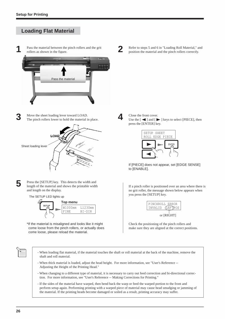
Pass the material between the pinch rollers and the gritrollers as shown in the figure.1
Move the sheet loading lever toward LOAD.The pinch rollers lower to hold the material in place.3 Close the front cover.
Use the [ ] and [ ] keys to select [PIECE], thenpress the [ENTER] key.
4
Sheet loading lever
Loading Flat Material
Refer to steps 5 and 6 in "Loading Roll Material," andposition the material and the pinch rollers correctly.2
- When loading flat material, if the material touches the shaft or roll material at the back of the machine, remove theshaft and roll material.
- When thick material is loaded, adjust the head height. For more information, see "User's Reference --Adjusting the Height of the Printing Head."
- When changing to a different type of material, it is necessary to carry out feed correction and bi-directional correc-tion. For more information, see "User's Reference -- Making Corrections for Printing."
- If the sides of the material have warped, then bend back the warp or feed the warped portion to the front andperform setup again. Performing printing with a warped piece of material may cause head smudging or jamming ofthe material. If the printing heads become damaged or soiled as a result, printing accuracy may suffer.
Press the [SETUP] key. This detects the width andlength of the material and shows the printable widthand length on the display.
5 If a pinch roller is positioned over an area where there is no grit roller, the message shown below appears whenyou press the [SETUP] key.
PINCHROLL ERRORINVALID LEFTPOS
or [RIGHT]
Top menu
W1000mm L1230mmFINE BI-DIR
*If the material is misaligned and looks like it mightcome loose from the pinch rollers, or actually doescome loose, please reload the material.
Pass the material
Setup for Printing
Check the positioning of the pinch rollers andmake sure they are aligned at the correct positions.
The SETUP LED lights up
SETUP SHEETROLL EDGE PIECE
If [PIECE] does not appear, set [EDGE SENSE]to [ENABLE].
27
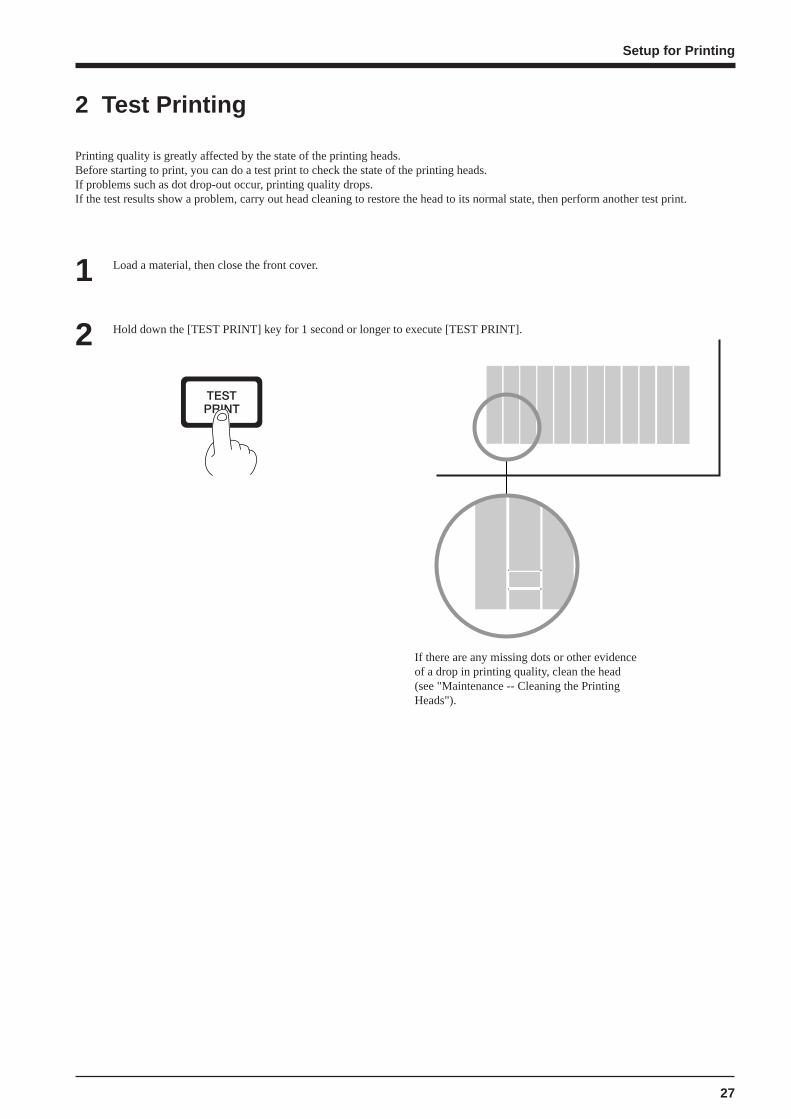
Load a material, then close the front cover.1
Hold down the [TEST PRINT] key for 1 second or longer to execute [TEST PRINT].2
If there are any missing dots or other evidenceof a drop in printing quality, clean the head(see "Maintenance -- Cleaning the PrintingHeads").
2 Test Printing
Printing quality is greatly affected by the state of the printing heads.Before starting to print, you can do a test print to check the state of the printing heads.If problems such as dot drop-out occur, printing quality drops.If the test results show a problem, carry out head cleaning to restore the head to its normal state, then perform another test print.
Setup for Printing

28
3 Setting the Printing Mode and Printing Direction
Before starting to print, set the printing mode and printing direction.On the control panel, press the [PRINT CONFIG] key and specify the printing mode and direction of printing.
Printing Mode
PHOTO: This is suitable for printing photographs.
SUPER: This is suitable for output with high imagequality, such as posters.
FINE: This is suitable for output with comparativelyhigh detail, such as posters.
FINE2: This is suitable for outputting posters and the(Factory like on various materials. default)
NORMAL: This is suitable for printing large-size itemswith comparatively high quality in a shorttime.
FAST: This is suitable for printing large-size items ina short time.
DRAFT: This can produce output in the shortest time. Itis suitable for checking layout and the like.
UNI-DIRECTION:Uni-directional printing.Printing is performed as the carriage moves from right to left.Printing quality is better than with [BI-DIRECTION].
BI-DIRECTION (factory default):Bi-directional printing.Printing is performed as the carriage moves from right to left,and also as it returns from left to right.Printing speed is faster than with [UNI-DIRECTION].
Printing Direction
Press the [ ] key to make the setting for the printingdirection.Use the [ ] and [ ] keys to display the printingdirection, then press the [ENTER] key.
3
DIRECTIONBI-DIRECTION
Press the [PRINT CONFIG] key.1 Use the [ ] and [ ] keys to choose the printingmode.2
PRINT MODEFINE
- Printing quality and output time vary according to the printing mode. Choose a mode that matches the task.Note that when the printing mode is set on the computer, the computer’s setting takes priority.
- The printing time for the same original data becomes increasingly longer in this sequence: DRAFT, FAST,NORMAL, FINE, FINE2, SUPER, and PHOTO. Also, with this procedure, the size of the output file generallygrows larger, and the processing time for creating the output file also becomes longer.It's also necessary to ensure enough memory on the computer.
Setup for Printing

29
Roll material must be placed at apredetermined shaft position.Failure to do so mayresult in dropping theroll, leading to injury.
Acceptable material widths
90 mm to 1371 mm (3.5 in. to 54 in.)
* N O T E : when loading material with a widthof 90 mm to 430 mm (3.5 in. to 17 in.), set the[EDGE SENSE] menu item to [DISABLE].
Pass the stoppers onto both ends of the shaft.(The shafts (2 pieces), stoppers (2 pieces), and screws(2 pieces) are included with the stand.)
* When passing the shaft through the stopper,be sure to loosen the screws on the stopperfirst.
1
Loading Roll Material
Align the media flange with the roll sheet edges, matching the roll sheet center ID.(The media flange is included with the stand.)2
1 Loading the Material
Stopper
Shaft
Media flange
Media flange
Media flange
50.8 mm(2 in.)
76.2 mm(3 in.)
Setup for Cutting
Setup for Cutting
Tighten loosely with the screws.

30
When viewed from the front, align so that the left-hand edge of the material is above any of the gritrollers and the right-hand edge is above the long gritroller.
5
Set the two shafts in place and apply the brake.3 Place the rolled material on the shaft.Pass the end of the material between the pinch rollersand the grit rollers so that it extends from the front ofthe unit.
4
Align the orientation of the material so that it isperfectly straight, and move the left-hand and right-hand pinch rollers so that they are above the gritrollers.Position the middle pinch roller over the grit roller thatlies between the left- and right-hand pinch rollers.
6
Rear
Rear
Roll material
* Position the left and rightpinch rollers over the material,near the edges.
Grit rollersGrit roller(Right)
Rail
Pinch roller (middle) Pinch roller (right)Pinch roller (left)
Shafts
Setup for Cutting
Brake
* The white stickers on the rail portion areguides for positioning the grit rollers.
* Make sure that the right-hand edge of the materialdoes not extend beyondthe right-hand edge of thegrit roller.
* Pull out the materialuntil it engages thesensor.

31
From the front of the machine, pull the center ofmaterial straight out toward the front. Without lettingany part of the entire piece of material pulled out tobecome slack, move the sheet loading lever all theway to “LOAD.”The pinch rollers lower to hold the material in place.
8
Press the [SETUP] key. This detects the width of thematerial and shows the printable width on the display.
*When [EDGE] is selected in step 9, the width ofthe loaded material is detected, then the frontedge of the material is aligned with the print-startlocation.
10
Align the left- and right-hand stoppers with the widthof the material and tighten the screws to secure inplace.
7 Rear
Roll material
Stopper
Screw
Media flange
RearEntire materialstretched taut
Close the front cover.Use the [ ] and [ ] keys to select [ROLL], thenpress the [ENTER] key.
*If cutting is to be performed from the edge of thematerial, select [EDGE] (If [EDGE] does notappear, set [EDGE SENSE] to [ENABLE]).
9
Top menu
W1000mm L ---mmFINE BI-DIR
The SETUP LED lights up
If a pinch roller is positioned over an area where there isno grit roller, the message shown below appears whenyou press the [SETUP] key.
SETUP SHEETROLL EDGE PIECE
PINCHROLL ERRORINVALID LEFTPOS
or [RIGHT]
Setup for Cutting
* If there is any slack in the loaded material, the material maymove at an angle and come loose from the pinch rollers.
Check the positioning of the pinch rollers and makesure they are aligned at the correct positions.
Sheet loading lever
32
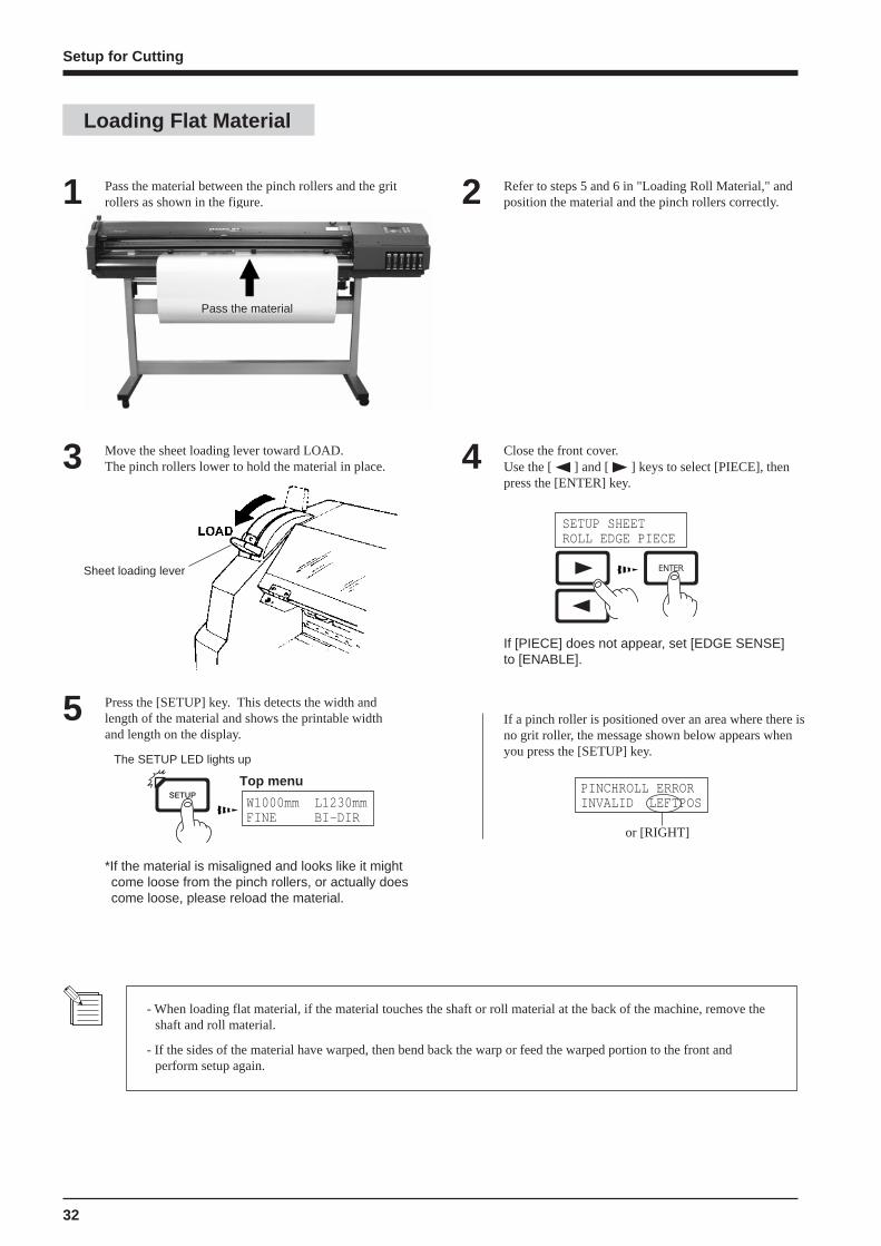
Pass the material between the pinch rollers and the gritrollers as shown in the figure.1
Move the sheet loading lever toward LOAD.The pinch rollers lower to hold the material in place.3 Close the front cover.
Use the [ ] and [ ] keys to select [PIECE], thenpress the [ENTER] key.
4
Sheet loading lever
Loading Flat Material
Refer to steps 5 and 6 in "Loading Roll Material," andposition the material and the pinch rollers correctly.2
- When loading flat material, if the material touches the shaft or roll material at the back of the machine, remove theshaft and roll material.
- If the sides of the material have warped, then bend back the warp or feed the warped portion to the front andperform setup again.
Press the [SETUP] key. This detects the width andlength of the material and shows the printable widthand length on the display.
5 If a pinch roller is positioned over an area where there isno grit roller, the message shown below appears whenyou press the [SETUP] key.
PINCHROLL ERRORINVALID LEFTPOS
or [RIGHT]
The SETUP LED lights up
Top menu
W1000mm L1230mmFINE BI-DIR
*If the material is misaligned and looks like it mightcome loose from the pinch rollers, or actually doescome loose, please reload the material.
SETUP SHEETROLL EDGE PIECE
Pass the material
Setup for Cutting
If [PIECE] does not appear, set [EDGE SENSE]to [ENABLE].
33
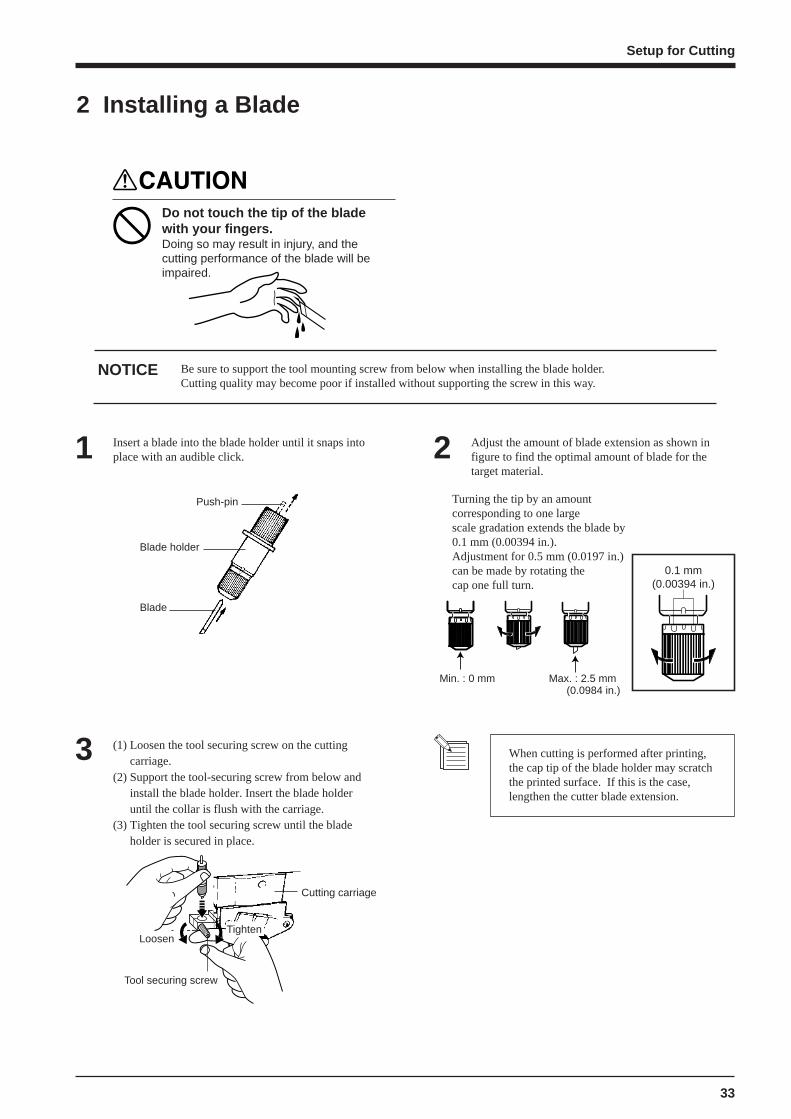
2 Installing a Blade
Do not touch the tip of the bladewith your fingers.Doing so may result in injury, and thecutting performance of the blade will beimpaired.
Be sure to support the tool mounting screw from below when installing the blade holder.Cutting quality may become poor if installed without supporting the screw in this way.
NOTICE
Push-pin
Blade holder
Blade
Insert a blade into the blade holder until it snaps intoplace with an audible click.1
Loosen
Tool securing screw
Tighten
Cutting carriage
(1) Loosen the tool securing screw on the cuttingcarriage.
(2) Support the tool-securing screw from below andinstall the blade holder. Insert the blade holderuntil the collar is flush with the carriage.
(3) Tighten the tool securing screw until the bladeholder is secured in place.
3
Adjust the amount of blade extension as shown infigure to find the optimal amount of blade for thetarget material.
2
Min. : 0 mm Max. : 2.5 mm(0.0984 in.)
0.1 mm(0.00394 in.)
When cutting is performed after printing,the cap tip of the blade holder may scratchthe printed surface. If this is the case,lengthen the cutter blade extension.
Setup for Cutting
Turning the tip by an amountcorresponding to one largescale gradation extends the blade by0.1 mm (0.00394 in.).Adjustment for 0.5 mm (0.0197 in.)can be made by rotating thecap one full turn.
34
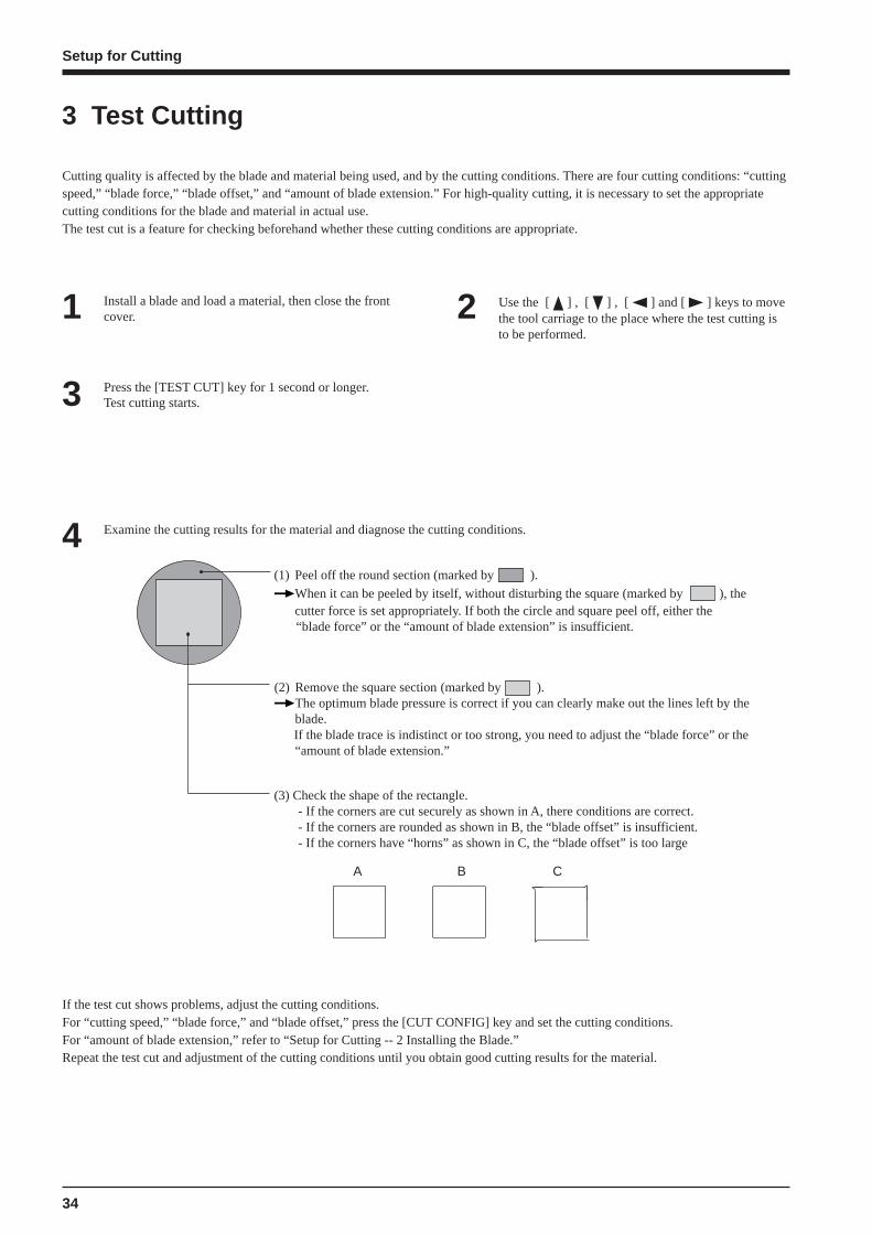
3 Test Cutting
Cutting quality is affected by the blade and material being used, and by the cutting conditions. There are four cutting conditions: “cuttingspeed,” “blade force,” “blade offset,” and “amount of blade extension.” For high-quality cutting, it is necessary to set the appropriatecutting conditions for the blade and material in actual use.The test cut is a feature for checking beforehand whether these cutting conditions are appropriate.
Install a blade and load a material, then close the frontcover.1 Use the [ ] , [ ] , [ ] and [ ] keys to move
the tool carriage to the place where the test cutting isto be performed.
2
Press the [TEST CUT] key for 1 second or longer.Test cutting starts.3
Examine the cutting results for the material and diagnose the cutting conditions.4(1) Peel off the round section (marked by ).
When it can be peeled by itself, without disturbing the square (marked by ), thecutter force is set appropriately. If both the circle and square peel off, either the “blade force” or the “amount of blade extension” is insufficient.
(2) Remove the square section (marked by ).The optimum blade pressure is correct if you can clearly make out the lines left by theblade.
If the blade trace is indistinct or too strong, you need to adjust the “blade force” or the“amount of blade extension.”
(3) Check the shape of the rectangle. - If the corners are cut securely as shown in A, there conditions are correct. - If the corners are rounded as shown in B, the “blade offset” is insufficient. - If the corners have “horns” as shown in C, the “blade offset” is too large
A B C
If the test cut shows problems, adjust the cutting conditions.For “cutting speed,” “blade force,” and “blade offset,” press the [CUT CONFIG] key and set the cutting conditions.For “amount of blade extension,” refer to “Setup for Cutting -- 2 Installing the Blade.”Repeat the test cut and adjustment of the cutting conditions until you obtain good cutting results for the material.
Setup for Cutting
35
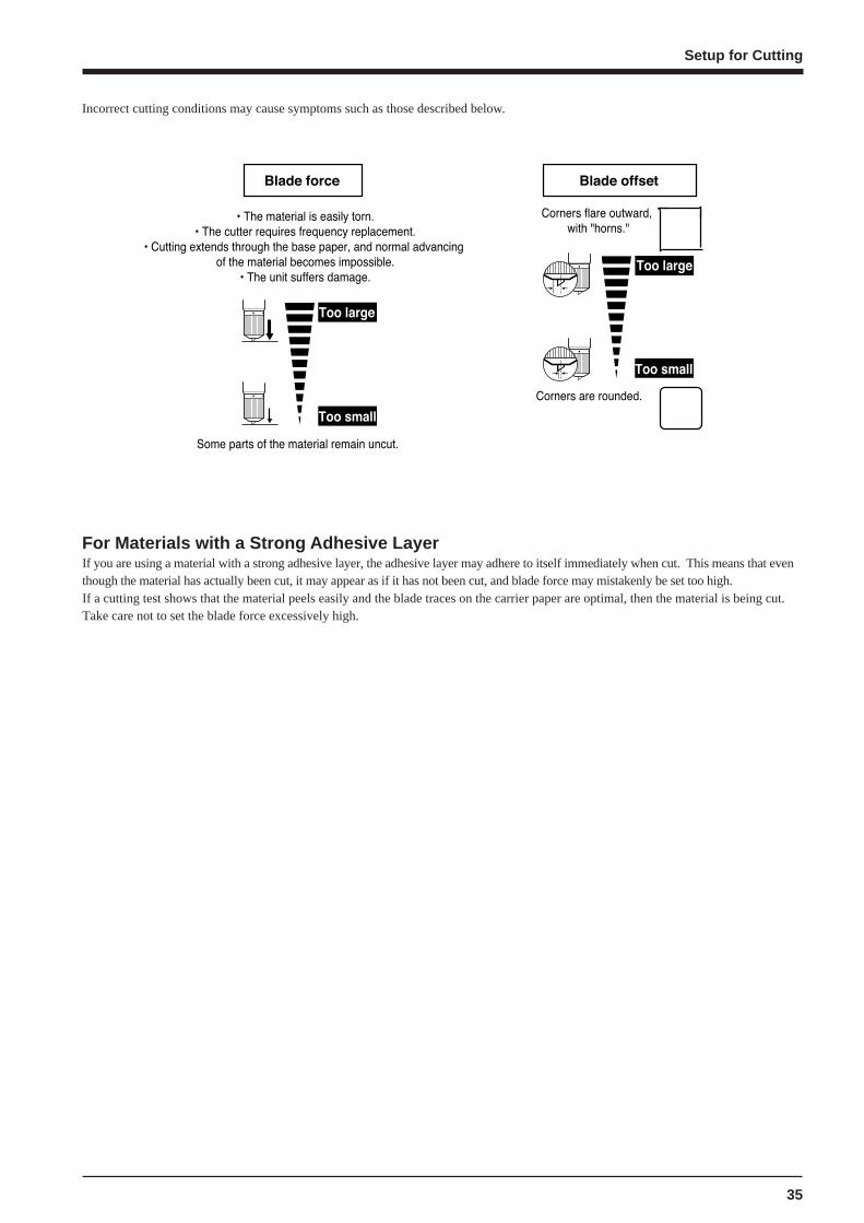
Incorrect cutting conditions may cause symptoms such as those described below.
For Materials with a Strong Adhesive LayerIf you are using a material with a strong adhesive layer, the adhesive layer may adhere to itself immediately when cut. This means that eventhough the material has actually been cut, it may appear as if it has not been cut, and blade force may mistakenly be set too high.If a cutting test shows that the material peels easily and the blade traces on the carrier paper are optimal, then the material is being cut.Take care not to set the blade force excessively high.
Setup for Cutting

36
Before performing printing and cutting, set up the machine as follows.
1 Loading the MaterialRefer to “Setup for Printing -- 1 Loading the Material” and load the material correctly.
2 Installing a BladeRefer to “Setup for Cutting -- 2 Installing the Blade” and install the blade correctly.
3 Test PrintingRefer to “Setup for Printing -- 2 Printing Test” and check the state of the heads.
4 Setting the Printing Mode and Printing DirectionRefer to “Setup for Printing -- 3 Selecting the Printing Mode and Direction of Printing” and make the settings for the modes.
5 Test CuttingRefer to “Setup for Cutting -- 3 Cutting Test” and perform a cutting test and adjust the cutting conditions.
Setup for Printing and Cutting
Setup for Printing and Cutting
37
Opening the front cover while printing is in progress causes an emergency stop. This means that printing maynot be carried out correctly even if operation is resumed, due to drop-out or misalignment of the image.To pause printing for any other reason than an emergency stop, press the [PAUSE] key.Note pressing the [PAUSE] key to pause operation may result in differing image quality before and after thepause. It is a good idea to avoid pausing operation while printing is in progress whenever possible.
NOTICE
If you leave the print head uncapped for a long time (for example, open the front cover while print head is in the middle of platen), print heads may get clogged and, in some cases it results in unrecoverable damage to the print head.
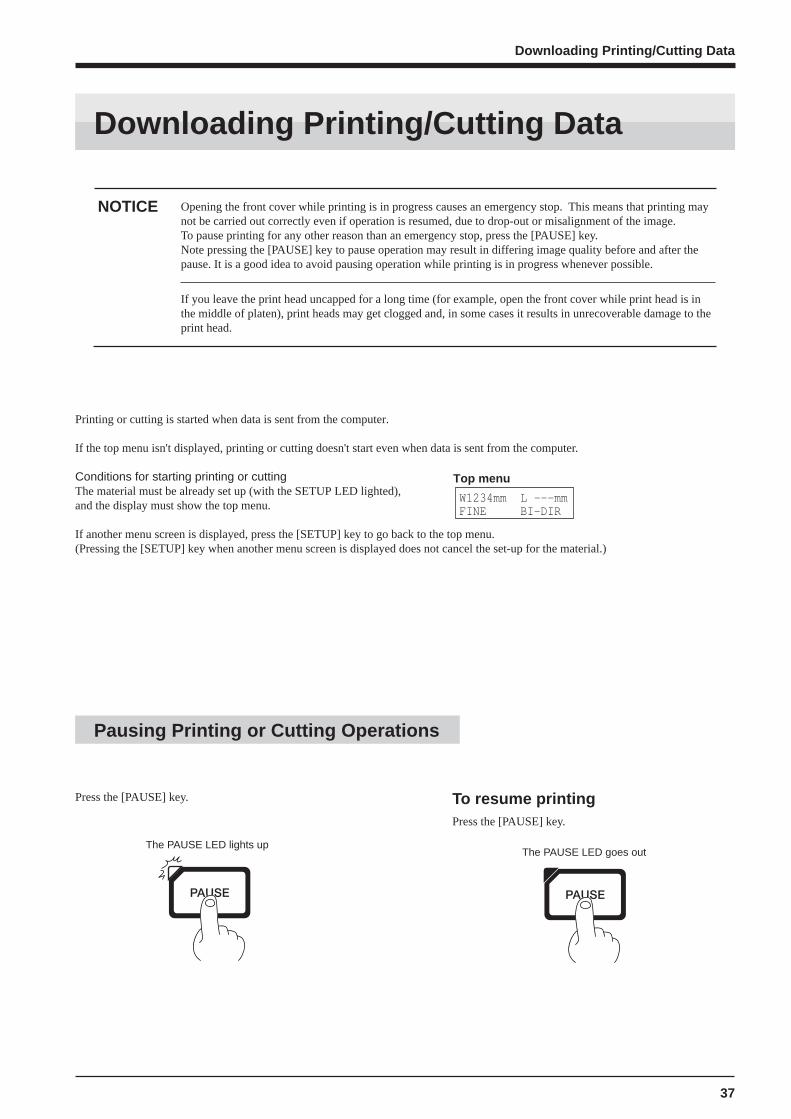
Press the [PAUSE] key. To resume printingPress the [PAUSE] key.
The PAUSE LED lights up
Pausing Printing or Cutting Operations
The PAUSE LED goes out
Downloading Printing/Cutting Data
Downloading Printing/Cutting Data
Printing or cutting is started when data is sent from the computer.
If the top menu isn't displayed, printing or cutting doesn't start even when data is sent from the computer.
Conditions for starting printing or cuttingThe material must be already set up (with the SETUP LED lighted),and the display must show the top menu.
If another menu screen is displayed, press the [SETUP] key to go back to the top menu.(Pressing the [SETUP] key when another menu screen is displayed does not cancel the set-up for the material.)
Top menu
W1234mm L ---mmFINE BI-DIR
38
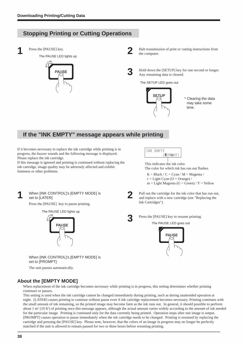
If it becomes necessary to replace the ink cartridge while printing is inprogress, the buzzer sounds and the following message is displayed.Please replace the ink cartridge.If this message is ignored and printing is continued without replacing theink cartridge, image quality may be adversely affected and exhibitfaintness or other problems.
INK EMPTY [KCMcmY]
This indicates the ink color.The color for which ink has run out flashes.
K = Black / C = Cyan / M = Magenta /c = Light Cyan (O = Orange) /m = Light Magenta (G = Green) / Y = Yellow
1 When [INK CONTROL]'s [EMPTY MODE] isset to [LATER]
Press the [PAUSE] key to pause printing.
The PAUSE LED lights up
When [INK CONTROL]'s [EMPTY MODE] isset to [PROMPT]
The unit pauses automatically.
2 Pull out the cartridge for the ink color that has run out,and replace with a new cartridge (see "Replacing theInk Cartridges").
3 Press the [PAUSE] key to resume printing.
The PAUSE LED goes out
Press the [PAUSE] key.1 Halt transmission of print or cutting instructions fromthe computer.2
The PAUSE LED lights up
Stopping Printing or Cutting Operations
If the "INK EMPTY" message appears while printing
Downloading Printing/Cutting Data
Hold down the [SETUP] key for one second or longer.Any remaining data is cleared.3The SETUP LED goes out
* Clearing the datamay take sometime.
About the [EMPTY MODE]When replacement of the ink cartridge becomes necessary while printing is in progress, this setting determines whether printingcontinues or pauses.This setting is used when the ink cartridge cannot be changed immediately during printing, such as during unattended operation atnight. [LATER] causes printing to continue without pause even if ink cartridge replacement becomes necessary. Printing continues with the small amount of ink remaining, so the printed image may become faint as the ink runs out. In general, it should possible to performabout 1 m2 (10 ft2) of printing once this message appears, although the actual amount varies widely according to the amount of ink neededfor the particular image. Printing is continued only for the data currently being printed. Operation stops after one image is output.[PROMPT] causes operation to pause immediately when the ink cartridge needs to be changed. Printing is resumed by replacing thecartridge and pressing the [PAUSE] key. Please note, however, that the colors of an image in progress may no longer be perfectlymatched if the unit is allowed to remain paused for two or three hours before resuming printing.

39
Cut the material from the rollEither of two methods can be used to separate a portion that's already been cut or printed from the roll. One method is to press the[SHEET CUT] key. The other method is to perform separation automatically by sending a material-cutting command from the computer.
Remov ing the Material from the machine
When separating the material by pressing the [SHEET CUT] key
Remov ing the Material
Press the [SETUP] key. Hold down for about 1second.1
The SETUP LED goes out
Move the sheet loading lever toward the back of theunit.The pinch rollers rise to release the material.
2Sheet loading lever
Open the front cover.To remove the material.3
Holding down the [SHEET CUT] key for 1 second or longersevers the material at the present location of the blade tip. Present location of
the blade tip
Cut or printedportion
The material is cut off here.
Remov ing the Material
* This operation isn't necessary whensending a material-cutting commandfrom the computer to separate thematerial automatically.
40
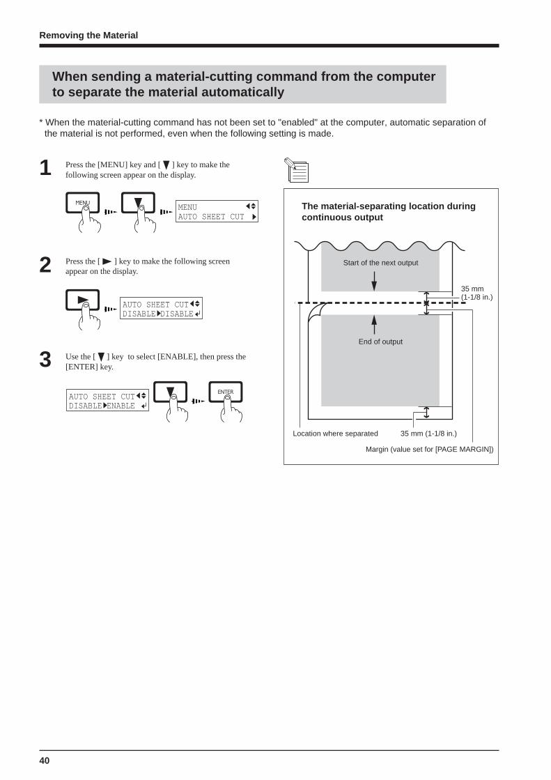
Press the [MENU] key and [ ] key to make thefollowing screen appear on the display.1
MENUAUTO SHEET CUT
Press the [ ] key to make the following screenappear on the display.2
AUTO SHEET CUTDISABLE DISABLE
Use the [ ] key to select [ENABLE], then press the[ENTER] key.3AUTO SHEET CUTDISABLE ENABLE
The material-separating location duringcontinuous output
Start of the next output
End of output
* When the material-cutting command has not been set to "enabled" at the computer, automatic separation ofthe material is not performed, even when the following setting is made.
When sending a material-cutting command from the computerto separate the material automatically
Remov ing the Material
35 mm(1-1/8 in.)
Location where separated 35 mm (1-1/8 in.)
Margin (value set for [PAGE MARGIN])

41
When operations are finished, move the sheet loading levertoward the back of the machine to raise the pinch rollers.The pinch rollers may be deformed if allowed to remain inthe lowered state.
NOTICESheet loading lever
The SETUP LED goes out
If the SETUP LED is lighted, press the [SETUP] key.Hold down for about 1 second.1 Move the sheet loading lever toward the back of the
unit and remove the material.2Sheet loading lever
The POWER LED goes out
5 Press the [POWER] key to switch off the power.The carriage moves to the standby position and the head is capped.If the carriage is already at the standby position, no movement takes place.
Remove the blade holder from the cutting carriage.3 Remove the blade.4
(1) Loosen the toolsecuring screw
Press the push-pin
Blade holder
Blade
Carriage
Standby position
When Operations Are Finished
When Operations Are Finished
(2) Remove the blade holder
42
Maintenance
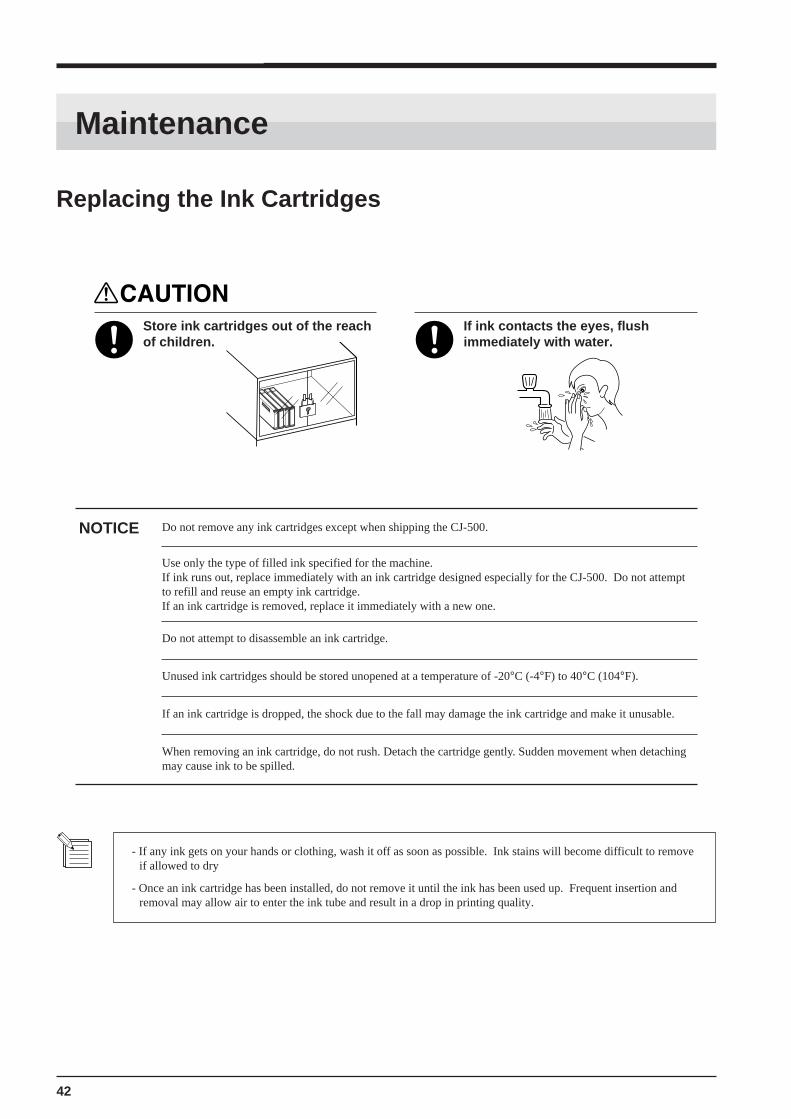
Store ink cartridges out of the reachof children.
If ink contacts the eyes, flushimmediately with water.
Do not remove any ink cartridges except when shipping the CJ-500.
Use only the type of filled ink specified for the machine.If ink runs out, replace immediately with an ink cartridge designed especially for the CJ-500. Do not attemptto refill and reuse an empty ink cartridge.If an ink cartridge is removed, replace it immediately with a new one.
NOTICE
Do not attempt to disassemble an ink cartridge.
Unused ink cartridges should be stored unopened at a temperature of -20°C (-4°F) to 40°C (104°F).
If an ink cartridge is dropped, the shock due to the fall may damage the ink cartridge and make it unusable.
- If any ink gets on your hands or clothing, wash it off as soon as possible. Ink stains will become difficult to removeif allowed to dry
- Once an ink cartridge has been installed, do not remove it until the ink has been used up. Frequent insertion andremoval may allow air to enter the ink tube and result in a drop in printing quality.
When removing an ink cartridge, do not rush. Detach the cartridge gently. Sudden movement when detachingmay cause ink to be spilled.
Replacing the Ink Cartridges
Maintenance

43
Maintenance
Remove the ink cartridge from the ink-cartridge port.1
Ink cartridge ports
PIGMENT = pigment ink DYE = dye ink
Use only the type of ink currently filled in the machine.The present ink type is displayed when the power is turned on.
With pigment inks, do not insert ink cartridges for orange or green when using light cyan and light magenta. Also, do notinsert the ink cartridges for light cyan or light magenta when using orange and green.If ink cartridges other than the filled type or color are installed, printed color will be inaccurate.
To change the type of ink, you must use an optionally available cleaning cartridge to flush the ink. For more informa-tion, see "Maintenance -- Changing the Type of Ink."
UNKNOWN TYPE = No ink is filled.PIGMENT CMYKLcLm = Pigment ink (cyan, magenta, yellow, black, light cyan, and light magenta)PIGMENT CMYKOrGr = Pigment ink (cyan, magenta, yellow, black, orange, and green)DYE CMYKLcLm = Dye ink (cyan, magenta, yellow, black, light cyan, and light magenta)
Press the key
Roland CJ-500 Ver.1.00
Roland CJ-500PIGMENT CMYKLcLm
Insert new ink cartridge.2
44
Maintenance
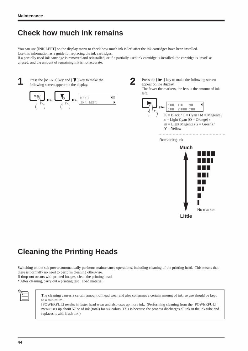
You can use [INK LEFT] on the display menu to check how much ink is left after the ink cartridges have been installed.Use this information as a guide for replacing the ink cartridges.If a partially used ink cartridge is removed and reinstalled, or if a partially used ink cartridge is installed, the cartridge is "read" asunused, and the amount of remaining ink is not accurate.
Press the [MENU] key and [ ] key to make thefollowing screen appear on the display.1 Press the [ ] key to make the following screen
appear on the display.The fewer the markers, the less is the amount of inkleft.
2MENUINK LEFT
K C Mc m Y
K = Black / C = Cyan / M = Magenta /c = Light Cyan (O = Orange) /m = Light Magenta (G = Green) /Y = Yellow
Remaining ink
Much
LittleNo marker
Check how much ink remains
Cleaning the Printing Heads
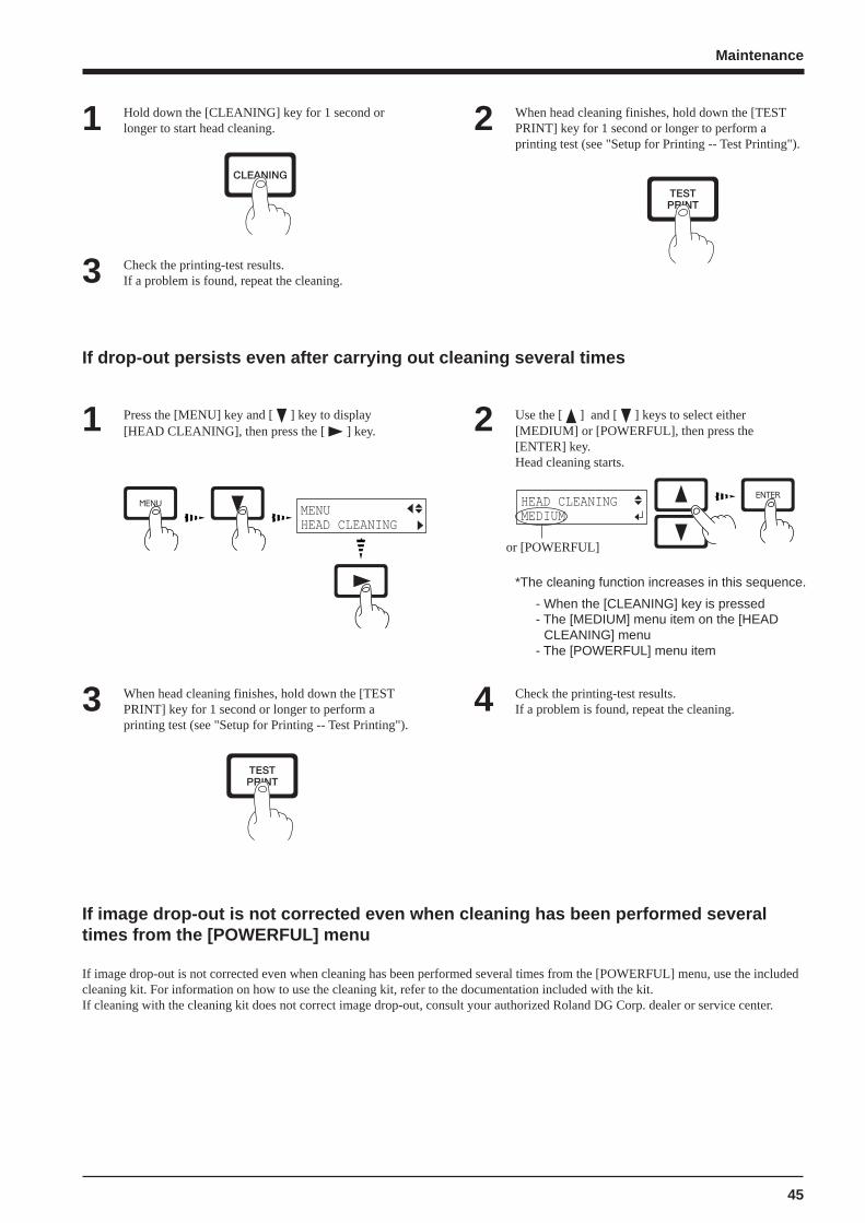
Switching on the sub power automatically performs maintenance operations, including cleaning of the printing head. This means thatthere is normally no need to perform cleaning otherwise.If drop-out occurs with printed images, clean the printing head.* After cleaning, carry out a printing test. Load material.
The cleaning causes a certain amount of head wear and also consumes a certain amount of ink, so use should be keptto a minimum.[POWERFUL] results in faster head wear and also uses up more ink. (Performing cleaning from the [POWERFUL]menu uses up about 57 cc of ink (total) for six colors. This is because the process discharges all ink in the ink tube andreplaces it with fresh ink.)
45
Maintenance
If image drop-out is not corrected even when cleaning has been performed several times from the [POWERFUL] menu, use the includedcleaning kit. For information on how to use the cleaning kit, refer to the documentation included with the kit.If cleaning with the cleaning kit does not correct image drop-out, consult your authorized Roland DG Corp. dealer or service center.
If drop-out persists even after carrying out cleaning several times
Press the [MENU] key and [ ] key to display[HEAD CLEANING], then press the [ ] key.1 Use the [ ] and [ ] keys to select either
[MEDIUM] or [POWERFUL], then press the[ENTER] key.Head cleaning starts.
2
MENUHEAD CLEANING
HEAD CLEANINGMEDIUM
When head cleaning finishes, hold down the [TESTPRINT] key for 1 second or longer to perform aprinting test (see "Setup for Printing -- Test Printing").
3 Check the printing-test results.If a problem is found, repeat the cleaning.4
Hold down the [CLEANING] key for 1 second orlonger to start head cleaning.1 When head cleaning finishes, hold down the [TEST
PRINT] key for 1 second or longer to perform aprinting test (see "Setup for Printing -- Test Printing").
2
Check the printing-test results.If a problem is found, repeat the cleaning.3
or [POWERFUL]
*The cleaning function increases in this sequence.
- When the [CLEANING] key is pressed- The [MEDIUM] menu item on the [HEAD
CLEANING] menu- The [POWERFUL] menu item
If image drop-out is not corrected even when cleaning has been performed severaltimes from the [POWERFUL] menu

46
Maintenance
To change the type of ink in use, change the ink set on the LED.Ink replacement requires three optionally available cleaning cartridges.
Press the [MENU] key and [ ] key to make thefollowing screen appear on the display.1 Press the [ ] key to make the following screen
appear on the display.2
Use the [ ] key to select [CHANGE INK SET], thenpress the [ ] key.3 Use the [ ] and [ ] keys to select the new type of
ink to use, then press the [ENTER] key.4
When the display shown in the figure appears, discardthe discharged ink in the drain bottle.* Be sure to discard the discharged ink.
Attempting to replace the ink while discharged inkremains may cause discharged ink to overflow fromthe bottle.
5 Remount the drain bottle and press the [ENTER] key todisplay the screen shown in the figure.6
When all ink cartridges have been removed, inkreplacement starts. Follow the messages on thedisplay to carry out the procedure.
7 When the display shown in the figure appears, insertthe ink cartridge to be newly used.8
When the display shown in the figure appears, inkreplacement is finished.Press the [SETUP] key to go back to the top menu.
9
MENUINK CONTROL
INK CONTROLEMPTY MODE
INK CONTROLCHANGE INK SET
PIG. CMYKLcLm (Pigment ink : cyan, magenta, yellow, black, light cyan, and light magenta)PIG. CMYKOrGr (Pigment ink : cyan, magenta, yellow, black, orange, and green)DYE CMYKLcLm (Dye ink : cyan, magenta, yellow, black, light cyan, and light magenta)
CHANGE INK SETPIG.CMYKLcLm
DISCARD DRAIN INK
REMOVE CARTRIDGE [KCMcmY]
SET CL-LIQUID [KCMcmY]
Insert a cleaning cartridge into the ink cartridge portfor the flashing color.
REMOVE CL-LIQUID [KCMcmY]
Remove the cleaning cartridge from the ink cartridgeport for the flashing color.
K = Black C = Cyan M = Magenta c = Light Cyan (O = Orange)m = Light Magenta (G = Green) Y = Yellow
SET CARTRIDGE [KCMOGY]
Messages appearing during ink replacement
Changing the Type of Ink
CHANGE INK SETPIG.CMYKOrGr

47
Maintenance
Replacing the Cutter Blade
Do not touch the tip of the bladewith your fingers.Doing so may result in injury, and thecutting performance of the blade will beimpaired.
Remove the blade holder from the cutting carriage.1 Remove the old blade.2
(1) Loosen the toolsecuring screw
(2) Remove the blade holder
Press the push-pin
Blade holder
Oldblade
Push-pin
Blade holder
Newblade
Replace with a new blade.3
Loosen
Tool securing screw
Tighten
Cutting carriage
(1) Loosen the tool securing screw on the cuttingcarriage.
(2) Support the tool-securing screw from below andinstall the blade holder. Insert the blade holderuntil the collar is flush with the carriage.
(3) Tighten the tool securing screw until the bladeholder is secured in place.
4
48
Maintenance
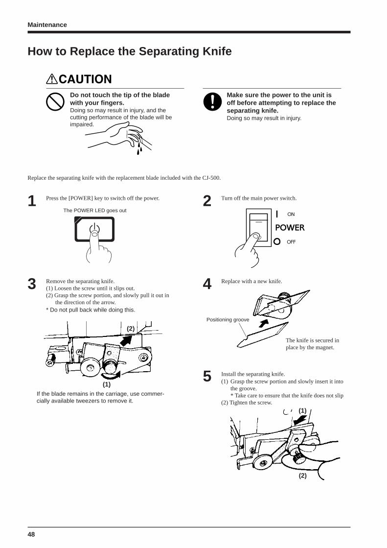
Replace the separating knife with the replacement blade included with the CJ-500.
Make sure the power to the unit isoff before attempting to replace theseparating knife.Doing so may result in injury.
Press the [POWER] key to switch off the power.1 Turn off the main power switch.2The POWER LED goes out
Remove the separating knife.(1) Loosen the screw until it slips out.(2) Grasp the screw portion, and slowly pull it out in
the direction of the arrow.* Do not pull back while doing this.
3 Replace with a new knife.4
Install the separating knife.(1) Grasp the screw portion and slowly insert it into
the groove.* Take care to ensure that the knife does not slip
(2) Tighten the screw.
5
Positioning groove
The knife is secured inplace by the magnet.
How to Replace the Separating Knife
Do not touch the tip of the bladewith your fingers.Doing so may result in injury, and thecutting performance of the blade will beimpaired.
(2)
(1)If the blade remains in the carriage, use commer-cially available tweezers to remove it.
(1)
(2)

49
Maintenance
Cleaning the bodyUse water or ethyl alcohol to clean, and wipe gently with a clean cloth. Wipe the operation panel and display gently with a clean, dry, andsoft cloth.
Cleaning the platenIf the platen is dirty clean with ethyl alcohol or water and wipe gently with a cloth.
Cleaning the grit rollersUse a commercially available brush to remove dust and other detritus. Brushhorizontally while rotating the grit rollers.Any adhering grime may prevent the material from being held in place securely.
Cleaning the pinch rollersUse water or ethyl alcohol and clean with a soft cloth.
Cleaning the front coverUse water or ethyl alcohol and clean with a soft cloth.
Cleaning the blade holder capIf material debris is adhering to the inner surface of the cap for the blade holder, loosen and remove the cap, then remove the materialdebris.
Never lubricate the mechanisms.
Use a small amount of water or ethyl alcohol for cleaning the covers. Never use solvents such as benzene orthinner.
Periodically clean the platen. Attractive printing may become impossible if the platen is soiled.
Do not touch the printing heads or allow the printing heads to come in contact with anything except ink.
NOTICE When performing cleaning, turn off the main power switch.* Before turning off the main power, press the [POWER] key to switch off the sub power.
When the Product Needs Cleaning
50
Maintenance
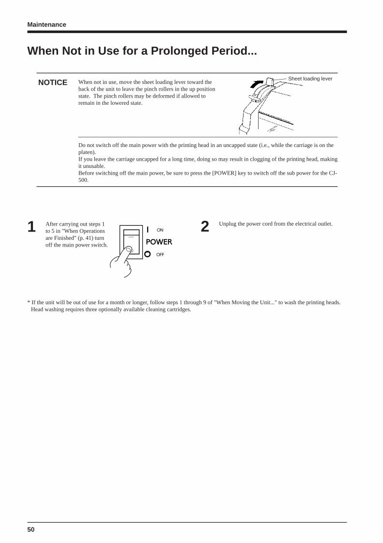
When Not in Use for a Prolonged Period...
When not in use, move the sheet loading lever toward theback of the unit to leave the pinch rollers in the up positionstate. The pinch rollers may be deformed if allowed toremain in the lowered state.
NOTICESheet loading lever
2 Unplug the power cord from the electrical outlet.After carrying out steps 1to 5 in "When Operationsare Finished" (p. 41) turn off the main power switch.
1
Do not switch off the main power with the printing head in an uncapped state (i.e., while the carriage is on theplaten).If you leave the carriage uncapped for a long time, doing so may result in clogging of the printing head, makingit unusable.Before switching off the main power, be sure to press the [POWER] key to switch off the sub power for the CJ-500.
* If the unit will be out of use for a month or longer, follow steps 1 through 9 of "When Moving the Unit..." to wash the printing heads.Head washing requires three optionally available cleaning cartridges.

51
Maintenance
When moving the unit, first carry out head washing, then secure the carriage in place. Head washing requiresthree optionally available cleaning cartridges.
NOTICE
If there is material loaded, hold down the [SETUP]key for 1 second or longer to cancel setup, thenremove the material (see "Remove the Material").
1 Press the [MENU] key and [ ] key to make thefollowing screen appear on the display.2
MENUINK CONTROL
Press the [ ] key to make the following screenappear on the display.3 Use the [ ] key to select [HEAD WASH], then press
the [ENTER] key.4INK CONTROLEMPTY MODE
INK CONTROLHEAD WASH
When the display shown in the figure appears, discardthe discharged ink in the drain bottle.* Be sure to discard the discharged ink.
Attempting to head washing while discharged inkremains may cause discharged ink to overflow fromthe bottle.
5 Mount the drain bottle and press the [ENTER] key todisplay the screen shown in the figure.6
When all ink cartridges have been removed, headwashing starts. Follow the messages on the display tocarry out the procedure.
7
DISCARD DRAIN INK
REMOVE CARTRIDGE [KCMcmY]
SET CL-LIQUID [KCMcmY]
Insert a cleaning cartridge into the inkcartridge port for the flashing color.
Continued on the next page
Messages appearing during head washing
K = Black C = Cyan M = Magenta c = Light Cyan (O = Orange)m = Light Magenta (G = Green) Y = Yellow
REMOVE CL-LIQUID [KCMcmY]
Remove the cleaning cartridge from the inkcartridge port for the flashing color.
When the display shown in the figure appears, headwashing is finished.Press the [POWER] key to switch off the sub power.
8
INK CONTROLHEAD WASH
The POWER LED goes out
When the POWERLED goes out, turn offthe main power switch.
9
When Moving the Unit...
52
Maintenance
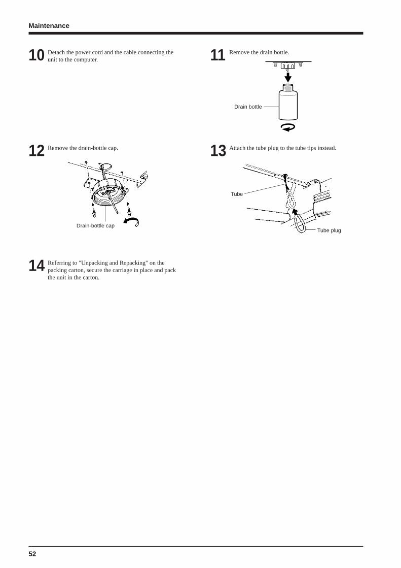
Detach the power cord and the cable connecting theunit to the computer.10 Remove the drain bottle.11
Remove the drain-bottle cap.12
Drain-bottle cap
Attach the tube plug to the tube tips instead.13
Referring to "Unpacking and Repacking" on thepacking carton, secure the carriage in place and packthe unit in the carton.
14
Tube
Tube plug
Drain bottle

53
User's Reference
Setting the Start Point
Set the print or cutting start position (base point) to the desired location.
Load material and install a blade, then press the[SETUP] key.1 Use the arrow keys to align the blade with the new
printing or cutting start location (base point).2
Press the [BASE POINT] key.3
To change the starting location that has been set...
• Set a new starting location in a different location.• Press the [SETUP] key to cancel the setup for the material (making the SETUP LED go out).
The BASE POINT LED lights up
When an align point has been set,it is released if the [BASE POINT]key is pressed.
Align withthe centerof the bladeinstalled onthe cuttingcarriage.
User's Reference
54
User's Reference
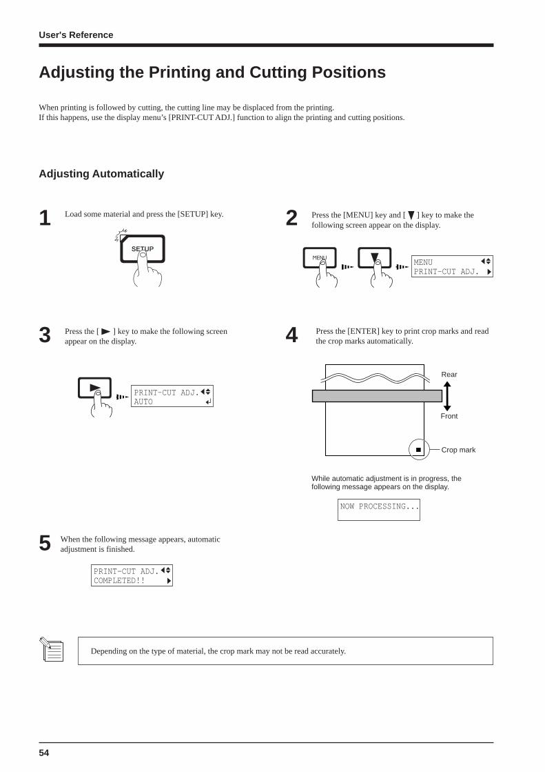
Adjusting the Printing and Cutting Positions
When printing is followed by cutting, the cutting line may be displaced from the printing.If this happens, use the display menu’s [PRINT-CUT ADJ.] function to align the printing and cutting positions.
Press the [ ] key to make the following screenappear on the display.3
Press the [MENU] key and [ ] key to make thefollowing screen appear on the display.2Load some material and press the [SETUP] key.1
4 Press the [ENTER] key to print crop marks and readthe crop marks automatically.
5 When the following message appears, automaticadjustment is finished.
Depending on the type of material, the crop mark may not be read accurately.
Adjusting Automatically
MENUPRINT-CUT ADJ.
PRINT-CUT ADJ.AUTO
Rear
Front
Crop mark
While automatic adjustment is in progress, thefollowing message appears on the display.
NOW PROCESSING...
PRINT-CUT ADJ.COMPLETED!!
55
User's Reference
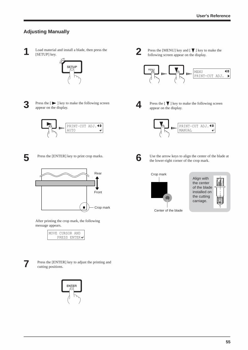
Press the [ ] key to make the following screenappear on the display.3
Press the [MENU] key and [ ] key to make thefollowing screen appear on the display.2Load material and install a blade, then press the
[SETUP] key.1
4 Press the [ ] key to make the following screenappear on the display.
Adjusting Manually
MENUPRINT-CUT ADJ.
PRINT-CUT ADJ.AUTO
Rear
Front
Crop mark
After printing the crop mark, the followingmessage appears.
5 Press the [ENTER] key to print crop marks. 6 Use the arrow keys to align the center of the blade atthe lower-right corner of the crop mark.
7 Press the [ENTER] key to adjust the printing andcutting positions.
Crop mark
MOVE CURSOR AND PRESS ENTER
PRINT-CUT ADJ.MANUAL
Align withthe centerof the bladeinstalled onthe cuttingcarriage.
Center of the blade
56
User's Reference
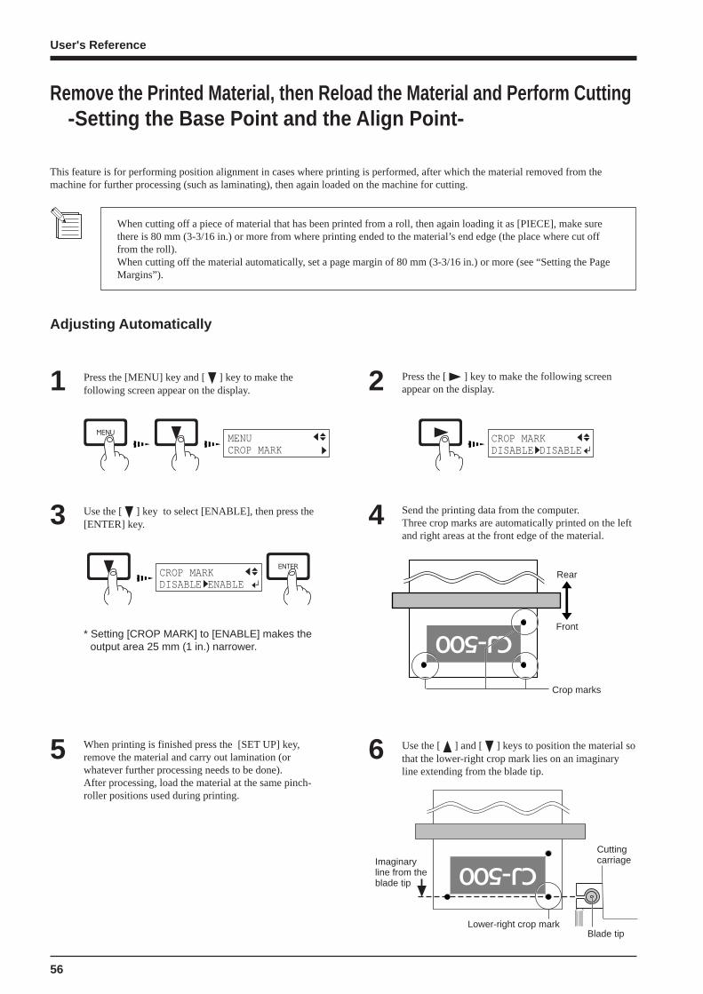
Remove the Printed Material, then Reload the Material and Perform Cutting -Setting the Base Point and the Align Point -
This feature is for performing position alignment in cases where printing is performed, after which the material removed from themachine for further processing (such as laminating), then again loaded on the machine for cutting.
When cutting off a piece of material that has been printed from a roll, then again loading it as [PIECE], make surethere is 80 mm (3-3/16 in.) or more from where printing ended to the material’s end edge (the place where cut offfrom the roll).When cutting off the material automatically, set a page margin of 80 mm (3-3/16 in.) or more (see “Setting the PageMargins”).
Adjusting Automatically
Press the [MENU] key and [ ] key to make thefollowing screen appear on the display.1 Press the [ ] key to make the following screen
appear on the display.2
Use the [ ] key to select [ENABLE], then press the[ENTER] key.3
When printing is finished press the [SET UP] key,remove the material and carry out lamination (orwhatever further processing needs to be done).After processing, load the material at the same pinch-roller positions used during printing.
5
Send the printing data from the computer.Three crop marks are automatically printed on the leftand right areas at the front edge of the material.
4
Use the [ ] and [ ] keys to position the material sothat the lower-right crop mark lies on an imaginaryline extending from the blade tip.
6
MENUCROP MARK
CROP MARKDISABLE DISABLE
CROP MARKDISABLE ENABLE
* Setting [CROP MARK] to [ENABLE] makes theoutput area 25 mm (1 in.) narrower.
Crop marks
Rear
Front
CuttingcarriageImaginary
line from theblade tip
Lower-right crop markBlade tip
57
User's Reference
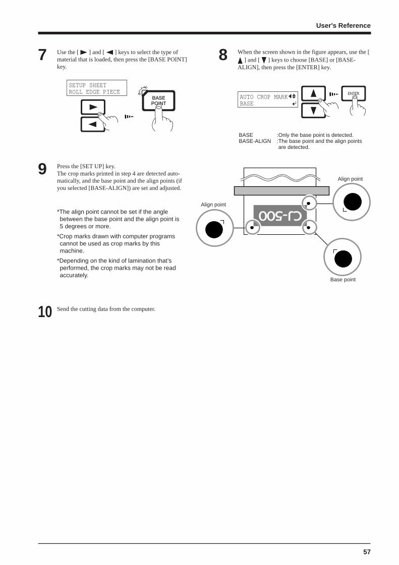
Use the [ ] and [ ] keys to select the type ofmaterial that is loaded, then press the [BASE POINT]key.
7 When the screen shown in the figure appears, use the [ ] and [ ] keys to choose [BASE] or [BASE-
ALIGN], then press the [ENTER] key.
8
Press the [SET UP] key.The crop marks printed in step 4 are detected auto-matically, and the base point and the align points (ifyou selected [BASE-ALIGN]) are set and adjusted.
9
Send the cutting data from the computer.10
*The align point cannot be set if the anglebetween the base point and the align point is5 degrees or more.
*Crop marks drawn with computer programs cannot be used as crop marks by thismachine.
*Depending on the kind of lamination that’sperformed, the crop marks may not be readaccurately.
SETUP SHEETROLL EDGE PIECE
AUTO CROP MARKBASE
BASE :Only the base point is detected.BASE-ALIGN :The base point and the align points
are detected.
Align point
Align point
Base point
58
User's Reference
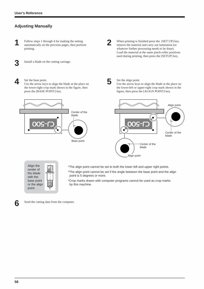
When printing is finished press the [SET UP] key,remove the material and carry out lamination (orwhatever further processing needs to be done).Load the material at the same pinch-roller positionsused during printing, then press the [SETUP] key.
2Follow steps 1 through 4 for making the settingautomatically on the previous pages, then performprinting.
1
Adjusting Manually
Install a blade on the cutting carriage.3
Set the base point.Use the arrow keys to align the blade at the place onthe lower-right crop mark shown in the figure, thenpress the [BASE POINT] key.
4 Set the align point.Use the arrow keys to align the blade at the place onthe lower-left or upper-right crop mark shown in thefigure, then press the [ALIGN POINT] key.
5
Send the cutting data from the computer.6
Base point
Align thecenter ofthe bladewith thebase pointor the alignpoint.
Align point
Align point
*The align point cannot be set to both the lower left and upper right points.
*The align point cannot be set if the angle between the base point and the alignpoint is 5 degrees or more.
*Crop marks drawn with computer programs cannot be used as crop marks by this machine.
Center of theblade
Center of theblade
Center of theblade

59
User's Reference
Making Corrections for Printing
Press the [MENU] key and [ ] key to make thefollowing screen appear on the display.1 Press the [ ] key to make the following screen
appear on the display.2
Press the [ ] key to make thefollowing screen appear on the display.3
MENUCALIBRATION
CALIBRATIONPRINTING ADJ.
When performing test printing for feed correction, load the material correctly (see "Setup for Printing -- Loading theMaterial"). If the material is not loaded correctly, an accurate test pattern may not be output.
Check the test pattern and choose avalue with no displacement.5
Press the [ ] key to make the following screenappear on the display.6
PRINTING ADJ.ADJUST
Press the [ ] key to make the following screenappear on the display.7
ADJUST -0.10% -0.10%
Use the [ ] and [ ] keys to set the value youchecked in step 4, then press the [ENTER] key.8ADJUST -0.10% +0.20%
-2.0% to +2.0% (In steps of 0.05%)
* Test printing prints the pattern in steps of 0.10%.
+0.30%
+0.25%
+0.20%
+0.15%
+0.10%
+0.05%
0.00%
-0.05%
-0.10%
-0.15%
Value with nodisplacement
Currentsetting
Test pattern
Press the [ENTER] key to start printing a test pattern.4
* Printing a Patternin Steps of 0.10%
This corrects for errors in the amount of feed of the grit rollers due the type of material.Be sure to make this setting when you have replaced the material with a different type.Correcting the amount of feed improves the dot-positioning accuracy in the feed direction, which can help enhance image quality.
Feed Correction
PRINTING ADJ.TEST PRINT
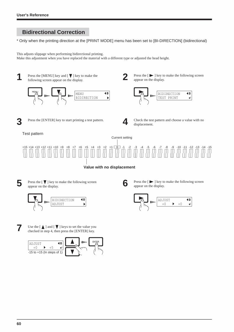
60
User's Reference
Bidirectional Correction* Only when the printing direction at the [PRINT MODE] menu has been set to [BI-DIRECTION] (bidirectional)
This adjusts slippage when performing bidirectional printing.Make this adjustment when you have replaced the material with a different type or adjusted the head height.
Press the [MENU] key and [ ] key to make thefollowing screen appear on the display.1 Press the [ ] key to make the following screen
appear on the display.2
Press the [ENTER] key to start printing a test pattern.3 Check the test pattern and choose a value with nodisplacement.4
MENUBIDIRECTION
BIDIRECTIONTEST PRINT
+15 +14 +13 +12 +11 +10 +9 +8 +7 +6 +5 +4 +3 +2 +1 0 -1 -2 -3 -4 -5 -6 -7 -8 -9 -10 -11 -12 -13 -14 -15
Test pattern
Value with no displacement
Current setting
Press the [ ] key to make the following screenappear on the display.5 Press the [ ] key to make the following screen
appear on the display.6
Use the [ ] and [ ] keys to set the value youchecked in step 4, then press the [ENTER] key.7
BIDIRECTIONADJUST
ADJUST +0 +0
-15 to +15 (In steps of 1)
ADJUST +0 +5
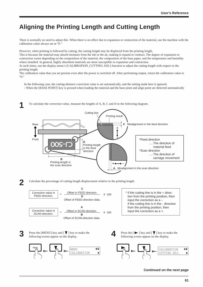
61
User's Reference
Aligning the Printing Length and Cutting Length
There is normally no need to adjust this. When there is no effect due to expansion or contraction of the material, use the machine with thecalibration value always set at “0.”
However, when printing is followed by cutting, the cutting length may be displaced from the printing length.This is because the material may absorb moisture from the ink or the air, making it expand or contract. The degree of expansion orcontraction varies depending on the composition of the material, the composition of the base paper, and the temperature and humiditywhere installed. In general, highly absorbent materials are more susceptible to expansion and contraction.At such times, use the display menu’s [CALIBRATION_CUTTING ADJ.] function to adjust the cutting length with respect to theprinting length.The calibration value that you set persists even after the power is switched off. After performing output, return the calibration value to“0.”
In the following case, the cutting-distance correction value is set automatically, and the setting made here is ignored.- When the [BASE POINT] key is pressed when loading the material and the base point and align point are detected automatically
To calculate the correction value, measure the lengths of A, B, C and D in the following diagram.1
Rear
Front
+
–
+ –
Printing resultCutting line
BPrinting length inthe scan direction
A Misalignment in the scan direction
C Misalignment in the feed direction
*Feed direction.....The direction of material feed
*Scan direction.....The direction of carriage movement
Calculate the percentage of cutting-length displacement relative to the printing length.2* If the cutting line is in the + direc-
tion from the printing position, theninput the correction as a -.If the cutting line is in the - directionfrom the printing position, theninput the correction as a +.
Correction value inFEED direction.
= X 100
Press the [MENU] key and [ ] key to make thefollowing screen appear on the display.3 Press the [ ] key and [ ] key to make the
following screen appear on the display.4
MENUCALIBRATION
CALIBRATIONCUTTING ADJ.
COffset in FEED direction.
DOffset of FEED-direction data.
Continued on the next page
DPrinting lengthin the feeddirection
Correction value inSCAN direction.
= X 100
AOffset in SCAN direction.
BOffset of SCAN-direction data.

62
User's Reference
Press the [ ] key to make the following screenappear on the display.5 Use the [ ] key to choose [FEED ADJUST] or
[SCAN ADJUST], then press the [ENTER] key.6
Press the [ ] key to make the following screenappear on the display.7 Input the correction value calculated in step (2).
Select the correction value with the [ ] [ ] key,and press the [ENTER] key.
8
CUTTING ADJ.FEED ADJUST
CUTTING ADJ.SCAN ADJUST
SCAN ADJUST+0.00% +0.00%

63
User's Reference
Performing Overprinting
Press the [MENU] key and [ ] key to make thefollowing screen appear on the display.1 Press the [ ] key to make the following screen
appear on the display.2MENUOVER PRINT
OVER PRINT NONE NONE
Use the [ ] and [ ] keys to choose the number ofpasses (two or three), then press the [ENTER] key.3OVER PRINT NONE 2
This prints the same image superimposed over the same location a number of times.When printing materials such as fabric, colors may not come out well with just a single printing pass. Overprinting can achieve darkerprinting results.You can choose either [2] (two passes) or [3] (three passes) as the number of passes for overprinting.Performing overprinting may result in ink smudges or stretch the fabric.
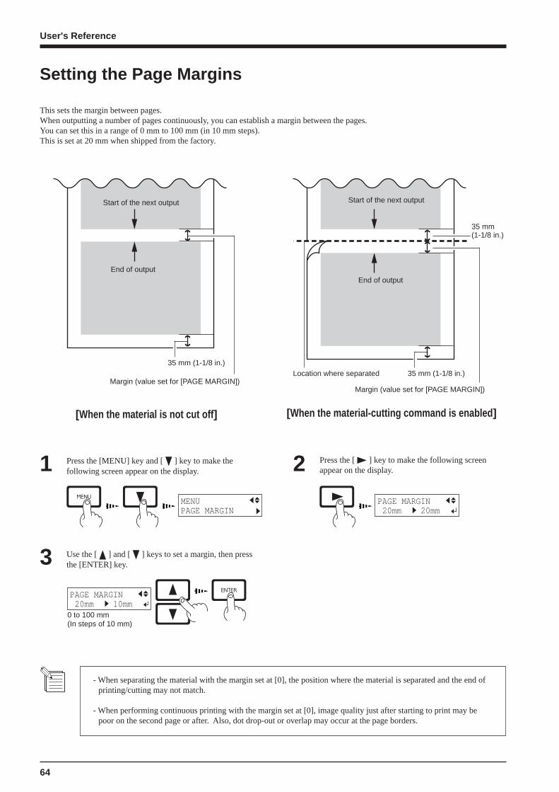
64
User's Reference
Setting the Page Margins
This sets the margin between pages.When outputting a number of pages continuously, you can establish a margin between the pages.You can set this in a range of 0 mm to 100 mm (in 10 mm steps).This is set at 20 mm when shipped from the factory.
[When the material-cutting command is enabled ]
Start of the next output
End of output
Margin (value set for [PAGE MARGIN])
Start of the next output
End of output
Margin (value set for [PAGE MARGIN])
Location where separated
35 mm(1-1/8 in.)
35 mm (1-1/8 in.)
[When the material is not cut off ]
Press the [MENU] key and [ ] key to make thefollowing screen appear on the display.1 Press the [ ] key to make the following screen
appear on the display.2
Use the [ ] and [ ] keys to set a margin, then pressthe [ENTER] key.3
MENUPAGE MARGIN
PAGE MARGIN 20mm 20mm
0 to 100 mm (In steps of 10 mm)
PAGE MARGIN 20mm 10mm
- When separating the material with the margin set at [0], the position where the material is separated and the end ofprinting/cutting may not match.
- When performing continuous printing with the margin set at [0], image quality just after starting to print may bepoor on the second page or after. Also, dot drop-out or overlap may occur at the page borders.
35 mm (1-1/8 in.)
65
User's Reference
About the Prefeed ([PREFEED]) Function
When using roll material, you can check in advance whether there is enough material available for the amount of printing or cutting data,or whether the material can be gripped correctly.When data is sent from the computer, the amount of material equal to the length of the data is automatically pulled out, and then printingor cutting begins. If material equal to the amount of data is not available, operation pauses and the following message appears on thedisplay.
SHEET TOO SHORT CONTINUE?
Press the [ENTER] key to perform printing or cutting.To cancel output, stop sending data from the computer, then hold down the [SETUP] keyfor 2 to 3 seconds.
When shipped from the factory, the prefeed ([PREFEED]) function is set to [ENABLE] as the default.
When using the optional media take-up unit (the TU-500), set the prefeed ([PREFEED]) function to [DISABLE].
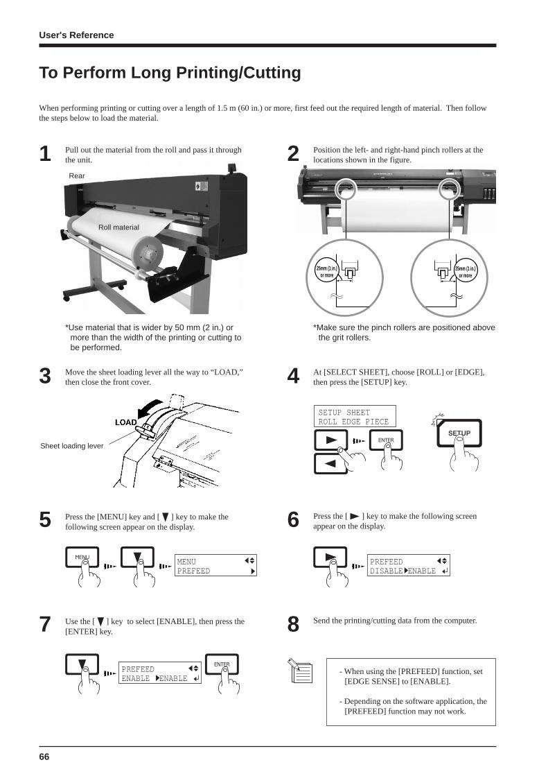
66
User's Reference
To Perform Long Printing/Cutting
When performing printing or cutting over a length of 1.5 m (60 in.) or more, first feed out the required length of material. Then followthe steps below to load the material.
1 Position the left- and right-hand pinch rollers at thelocations shown in the figure.2
*Use material that is wider by 50 mm (2 in.) ormore than the width of the printing or cutting tobe performed.
*Make sure the pinch rollers are positioned abovethe grit rollers.
Sheet loading lever
SETUP SHEETROLL EDGE PIECE
Move the sheet loading lever all the way to “LOAD,”then close the front cover.3 At [SELECT SHEET], choose [ROLL] or [EDGE],
then press the [SETUP] key.4
Press the [MENU] key and [ ] key to make thefollowing screen appear on the display.5 Press the [ ] key to make the following screen
appear on the display.6
Use the [ ] key to select [ENABLE], then press the[ENTER] key.7 Send the printing/cutting data from the computer.8
Rear
Pull out the material from the roll and pass it throughthe unit.
Roll material
25mm (1 in.)or more
25mm (1 in.)or more
MENUPREFEED
PREFEEDDISABLE ENABLE
PREFEEDENABLE ENABLE
- When using the [PREFEED] function, set[EDGE SENSE] to [ENABLE].
- Depending on the software application, the[PREFEED] function may not work.
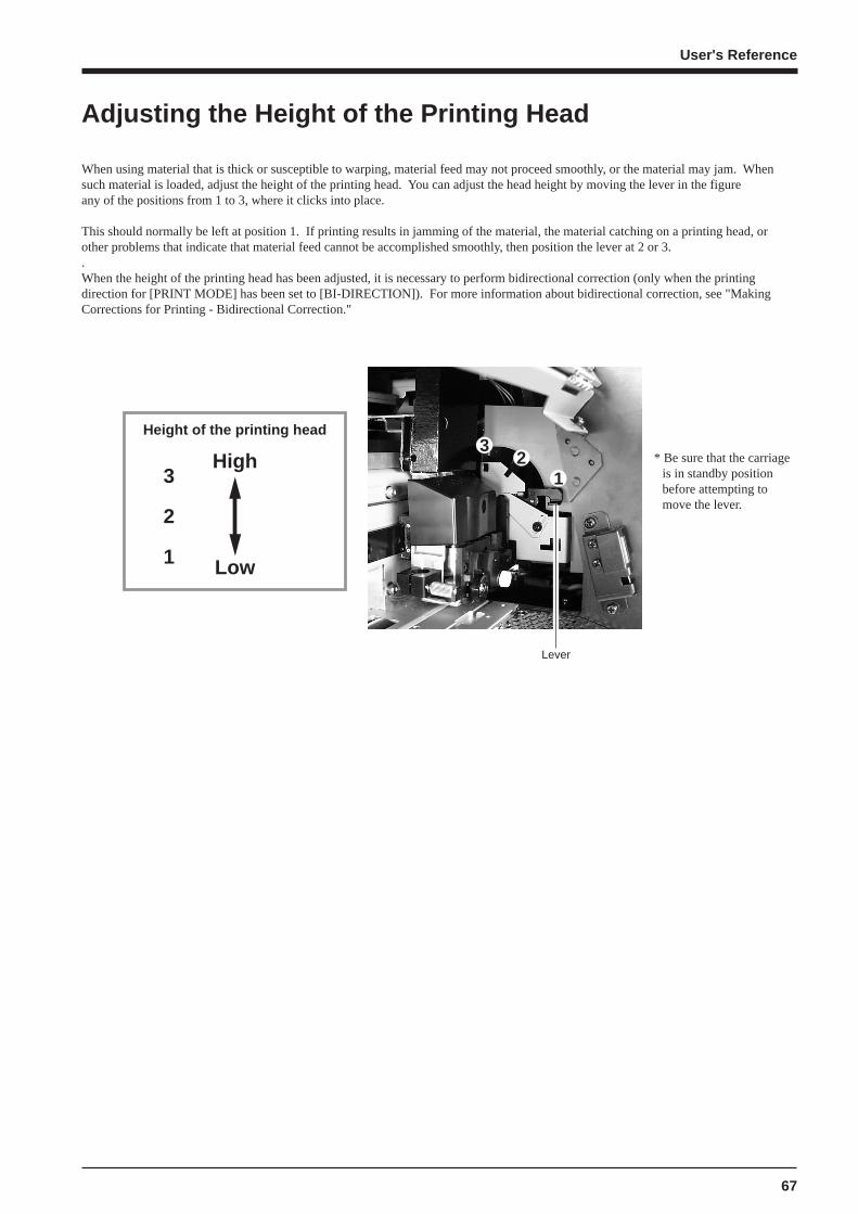
67
User's Reference
Adjusting the Height of the Printing Head
When using material that is thick or susceptible to warping, material feed may not proceed smoothly, or the material may jam. Whensuch material is loaded, adjust the height of the printing head. You can adjust the head height by moving the lever in the figureany of the positions from 1 to 3, where it clicks into place.
This should normally be left at position 1. If printing results in jamming of the material, the material catching on a printing head, orother problems that indicate that material feed cannot be accomplished smoothly, then position the lever at 2 or 3..When the height of the printing head has been adjusted, it is necessary to perform bidirectional correction (only when the printingdirection for [PRINT MODE] has been set to [BI-DIRECTION]). For more information about bidirectional correction, see "MakingCorrections for Printing - Bidirectional Correction."
Height of the printing head
3
2
1
High
Low
3
12
Lever
* Be sure that the carriageis in standby positionbefore attempting tomove the lever.
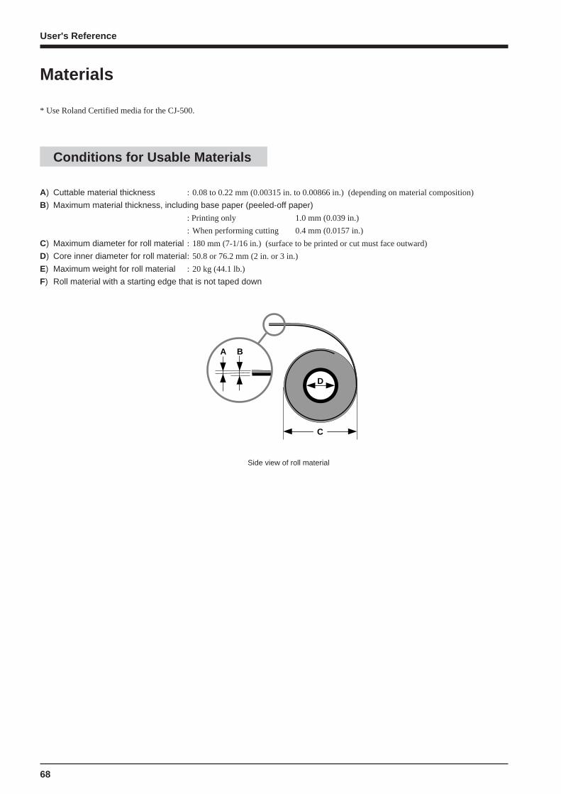
68
User's Reference
Materials
* Use Roland Certified media for the CJ-500.
Conditions for Usable Materials
C
D
A B
A) Cuttable material thickness : 0.08 to 0.22 mm (0.00315 in. to 0.00866 in.) (depending on material composition)
B) Maximum material thickness, including base paper (peeled-off paper)
: Printing only 1.0 mm (0.039 in.)
: When performing cutting 0.4 mm (0.0157 in.)
C) Maximum diameter for roll material : 180 mm (7-1/16 in.) (surface to be printed or cut must face outward)
D) Core inner diameter for roll material: 50.8 or 76.2 mm (2 in. or 3 in.)
E) Maximum weight for roll material : 20 kg (44.1 lb.)
F) Roll material with a starting edge that is not taped down
Side view of roll material

69
User's Reference
Acceptable material widths
90 mm to 430 mm (3.5 to 54 in.)
* However, when loading material with a width of 90 mm to 430 mm (3.5 to 17 in.), set the [EDGE SENSE] menu item to[DISABLE].
54 in. (approx. 1371 mm)
48 in. (approx. 1219 mm)
Material with a width 38 and 46 in.
Material with a width 30 and 36 in.
Material with a width 18 and 24 in.
46 in. (approx. 1168 mm)
36 in. (approx. 914 mm)
30 in. (approx. 762 mm)
(1*)(2*)
Material
18 in. (approx. 457 mm)
54 in. (approx. 1372 mm)
Material with a width 48 and 54 in. 170 mm
(6-11/16 in.)
24 in. (approx. 610 mm)
38 in. (approx. 965 mm)
(1*) Position of the pinch roller (middle) when using material with a width of 30, 36, 38 and 46 in.(2*) Position of the pinch roller (middle) when using material with a width of 48 and 54 in.
*Lowering the middle pinch roller during printing may damage the printing surface. At such times, position the pinchrollers away from above the grit rollers.
: Grit roller
: Pinch roller (left) : Pinch roller (right)
: Pinch roller (middle)* Make sure the left and right pinch rollers
are positioned above the grit rollers.
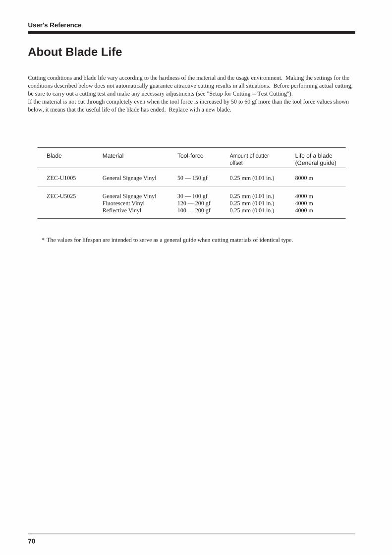
70
User's Reference
About Blade Life
Cutting conditions and blade life vary according to the hardness of the material and the usage environment. Making the settings for theconditions described below does not automatically guarantee attractive cutting results in all situations. Before performing actual cutting,be sure to carry out a cutting test and make any necessary adjustments (see "Setup for Cutting -- Test Cutting").If the material is not cut through completely even when the tool force is increased by 50 to 60 gf more than the tool force values shownbelow, it means that the useful life of the blade has ended. Replace with a new blade.
* The values for lifespan are intended to serve as a general guide when cutting materials of identical type.
Amount of cutteroffset
0.25 mm (0.01 in.)
0.25 mm (0.01 in.)0.25 mm (0.01 in.)0.25 mm (0.01 in.)
Life of a blade(General guide)
8000 m
4000 m4000 m4000 m
Tool-force
50 — 150 gf
30 — 100 gf120 — 200 gf100 — 200 gf
Material
General Signage Vinyl
General Signage VinylFluorescent VinylReflective Vinyl
Blade
ZEC-U1005
ZEC-U5025

71
User's Reference
The printing/cutting area along the horizontal plane (the direction in which the carriage moves) is determined by the position of the pinchrollers. The workable area spans the length between the two rollers, minus a margin of about 1.5 mm (about 0.06 in.) on both sides.If " PIECE" has been selected and material length (the distance in the X direction as shown in the figure) is 2,000 mm, the area is thesame as when "EDGE" has been chosen.
About the Printing/Cutting Area
* The arrows in the figure indicating the X and Y directions indicaterespectively the positive directions of the X axis and Y axis.
Max.: 1346 mm (53 in.)
19.2 mm (13/16 in.)
Pinch roller (right)
Printing/cutting area
Material
Max.: 24998 mm (984-1/8 in.)
10 mm(3/8 in.)
Approx. 1.5 mm (about 0.06 in.)
60 mm(about 2-1/8 in.)
When [PIECE] is selected
Pinch roller (left)
Approx. 19.2 mm(about 13/16 in.)
35 mm (1-1/8 in.)(If the material configuration is "EDGE" or "PIECE.")
10 mm(3/8 in.)
Approx. 1.5 mm (about 0.06 in.)
Printing/cutting coordinates origin (0, 0)
35 mm (1-1/8 in.)(If the material configuration is "EDGE" or "PIECE.")
When crop marks are printed, the printing or cutting area in the area shown above is reduced by an amount equal to the size of the cropmarks (12.5 mm (0.5 in.) + 12.5 mm (0.5 in.)).
12.5 mm(0.5 in.)
Pinch roller (left)
12.5 mm(0.5 in.)
The area shown above
The area when crop marks are printed
Printing or cutting area when crop marks are printed
Crop mark
The area shown above
Crop marks
12.5 mm(0.5 in.)
12.5 mm(0.5 in.)
Crop mark
Default area
Pinch roller (right)
Printing/cutting coordinates origin (0, 0)

72
User's Reference
Defaultvalue
Settingrange
FunctionSubmenuTopmenu
Key
— — — —This switches on and off the sub power . When thepower is switched on, the POWER LED lights up.
— — — —This detects the presence of material, and its dimensions,and shows the printable or cuttable size on the display.The SETUP LED flashes while detection of materialwidth is in progress. When setup finishes, the SETUPLED lights up continuously.Also press this key when removing the material.
— — — —The [PAUSE] key pauses operation. The PAUSE LEDlights up while paused.Pressing this key again cancels the paused state.Holding down the [SETUP] key for about 1 secondwhile paused causes remaining data to be cleared andcancels the material's setup state.
— — — —This sets the present blade position (blade center) at theprinting or cutting start location (base point).For more information, see "User's Reference --Setting the Start Point."
PRINTMODE
— [PRINT MODE]PHOTOSUPERFINEFINE2NORMALFASTDRAFT
[PRINTDIRECTION]UNI-DIRECTIONBI-DIRECTION
[PRINT MODE]FINE2
[PRINTDIRECTION]BI-DIREC-TION
This displays the [PRINT MODE] menu for settingimage quality.This is used to specify the printing quality and unidi-rectional or bidirectional printing.Settings cannot be made while printing is in progress.To exit the [PRINT MODE] menu screen, press the[MENU] key or the [CLEANING] key or the [SETUP]key.For more information, see "Setup for Printing -- Settingthe Printing quality and Printing direction."
— — — —This sets an align point for correction when the materialis not straight.The angle of the material, referenced from the basepoint, is stored in memory. Any angle of 5° or less maybe set.This setting is valid only when cutting.
FORCE — [FORCE]30 to 200 gf(In steps of 5 gf)
[SPEED]1 to 60 cm/s(In steps of 1 cm/s)[OFFSET]0 to 1.5 mm
(In steps of 0.025 mm)[UP-SPEED]1 to 60 cm/s(In steps of 1 cm/s)
[FORCE]50 gf
[SPEED]40 cm/s
[OFFSET]0.25 mm
[UP-SPEED]60 cm/s
This enters the menu for setting the conditions forcutting.You can set the values for blade force, cutting speed,blade offset compensation, and tool movement speedwhen raising the tool.For more information, see "Display Menus Flowchart."
Description of Keys

73
User's Reference
Defaultvalue
Settingrange
FunctionSubmenuTopmenu
Key
— — — —This cuts off the material at the present location of theblade tip. Press this to cut off the portion alreadyprinted or cut from the roll.You cannot sever a piece of material while printing orcutting is in progress.For more information, see "Removing the Material."
— — — —This enters the menu mode.When a menu is displayed, the [ ] and [ ] keysmove to the next menu,the [ ] moves to a submenu, and the [ ] keymoves to the previous screen.
— — — —This is used to accept, execute, or save the item shownon the display.
— — — —These move the material and the carriage.When a menu is displayed, these move among themenu items.
— — — —Holding down this key for 1 second or longer performsa printing test in an area of approximately 54 mm x 18mm (2.13 in. x 0.71 in.).Before starting to print, you can carry out a test printingto check the printing quality. For more information, see"Setup for Printing -- Test Printing."If there is a problem with the state of the heads, such asdot drop-out, perform head cleaning.
— — — —Holding down this key for 1 second or longer performscleaning for the printing heads.You can perform cleaning while in any state.For more information, see "Maintenance -- Cleaningthe Printing Heads."
— — — —Holding down this key for 1 second or longer performsa cutting test in an area of approximately 20 mm x 20mm (0.79 in. x 0.79 in.).For more information, see "Setup for Cutting -- TestCutting"If there are problems with the quality of cutting resultsfor the material, press the [CUT CONFIG] key andadjust the cutting conditions.
MENULANGUAGE
— ENGLISHJAPANESE
ENGLISHThis sets the language for screen messages. You canselect either English or Japanese.
+
— — — —This forces the tool to move up or down.

74
User's Reference
Description of MenusPressing the [MENU] key enters the menu mode.
Defaultvalue
SettingrangeFunctionSubmenuTop
menu
DEMO PRINT &CUT
— —This performs printing or cutting of sample data.[PRINT & CUT]: This outputs the sample data for printing and cutting.[PRINT]: This outputs the sample data for printing.[CUT]: This outputs the sample data for cutting.
CARIBRATION 0%
0%
This corrects for errors in the amount of feed of the grit rollers due thetype of material.Be sure to make this setting when you have replaced the material witha different type.Make this setting again when horizontal stripes are plainly visible onprinting results.[TEST PRINT]: This menu is for verifying the adjustment.[ADJUST]: This sets the correction value.For more information, see "User's Reference -- Making Corrections forPrinting -- Feed Correction"This corrects the cutting length relative to the print length (distancecorrection).For more information, see "User's Reference -- Aligning the PrintingLength and Cutting Length"[FEED ADJUST]: This sets the adjustment value for the material-feed
direction.[SCAN ADJUST]: This sets the adjustment value for the left-right
direction (the carriage-movement direction).
PRINTINGADJ.
CUTTINGADJ.
[PRINTING ADJ.]-2.0% to +2.0%(In steps of 0.05%)
[CUTTING ADJ.]-2.0% to +2.0%(In steps of 0.01%)
BIDIRECTION Correctionvalue when
shippedfrom thefactory
This adjusts for slippage when performing bidirectional printing.This must be readjusted when you have replaced the material with adifferent type or adjusted the head height.[TEST PRINT]: This menu is for verifying the adjustment.[ADJUST]: This sets the correction value.For more information, see "User's Reference -- Making Corrections forPrinting -- Bidirectional Correction."
TEST PRINTADJUST
-15 to +15(In steps of 1)
OVERPRINT
NONEYou can carry out the same printing superimposed over the samelocation. When printing materials such as fabric, colors may not comeout well with just a single printing pass.This should normally be set to [NONE].For more information, see "User's Reference -- Performing Overprint-ing."
— NONE/2/3
DRYINGTIME
NONEThis sets the drying time for the material. For materials with lowabsorbency that are difficult to dry, make the setting for a longer time.When printing is followed by cutting, cutting is performed afterwaiting for the set time.
— NONE/10 to 990 sec.(In steps of 10 sec.)
EDGESENSE
— ENABLE/DISABLE
ENABLEThis specifies whether detection of the front and rear edges of thematerial is enabled or disabled.This should normally be set to [ENABLE].When loading transparent material or material with a width of 90 to 430mm (3.5 to 17 in.), set this to [DISABLE]. When set to [DISABLE],then during material setup only the [ROLL] selection is available.
Description of Menu Items
CROP MARK — ENABLE/DISABLE
DISABLEThis specifies whether output of crop marks is enabled or disabled.When set to [ENABLE], crop marks are automatically added to thedata sent from the computer and printed.

75
User's Reference
Defaultvalue
SettingrangeFunctionSubmenuTop
menu
INKCONTROL
EMPTYMODE
FILL INK
PUMP UPHEAD WASH
CHANGEINK SET
[EMPTYMODE]
LATER/PROMPT
[CHANGEINK SET]
PIG.CMYKLcLm/PIG.CMYKOrGr/DYECMYKLcLm/
LATERWhen replacement of the ink cartridge becomes necessary whileprinting is in progress, this setting determines whether printingcontinues or pauses.This setting is used when the ink cartridge cannot be changed immedi-ately during printing, such as during unattended operation at night.[LATER] causes printing to continue without pause even if ink refillingbecomes necessary. Printing continues with the small amount of inkremaining, so the printed image may become faint as the ink runs out.In general, it should possible to perform about 1 m2 (10 ft2) of printingonce this message appears, although the actual varies widely accordingto the amount of ink needed for the particular image. Printing iscontinued only for the data currently being printed. Operation stopsafter one image is output.[PROMPT] causes operation to pause immediately when the inkcartridge needs to be changed. Printing is resumed by replacing thecartridge and pressing the [PAUSE] key. Please note, however, that thecolors of an image in progress may no longer be perfectly matched ifthe unit is allowed to remain paused for two or three hours beforeresuming printing.[FILL INK] : Refills the printing heads with ink. Normally there is noneed to do this, because refilling is automatic.[PUMP UP] : Drains ink from the printing heads.[HEAD WASH] : This washes the printing heads with optionallyavailable cleaning cartridges. For more information, see "Maintenance-- When Moving the Unit... ."[CHANGE INK SET] : Performs the [HEAD WASH] and [FILL INK]operations.This is used when switching the ink type. Before running this, choosethe type of ink to be used after the change.For more information, see "Maintenance -- Changing the Type of Ink."
TIME OUT NONEWhen a certain amount of time passes with no data sent from thecomputer, the current output is considered to be finished."TIME OUT" sets the time used for this determination.
— NONE/10 to 990 sec.(In steps of 10 sec.)
FACTORYDEFAULT
— — —This returns all menu settings to their original values when shippedfrom the factory.For more about the factory defaults for the various settings, see the"Default value" entry for each menu setting in this section.
PRINT-CUTADJ.
— AUTO/MANUAL
—[AUTO]: Alignment of the printing and cutting positions isperformed automatically.
[MANUAL]: Alignment of the printing and cutting positions isperformed manually.
For more information, see "User's Reference -- Adjusting the Printingand Cutting Positions"
SYSTEMREPORT
— — —This prints the current status of setting and other system information.
— mm/INCH mmThis selects millimeters or inches as the unit of measurement for thewidth displayed on the top menu after setting up the material. Wheninch display is used, values are displayed to the first digit to the right ofthe decimal point.
MENU UNIT
— 0 to 100 mm(In steps of 10 mm)
20 mmThis makes the setting for the margin between pages.When outputting a number of pages continuously, you can establish amargin between the pages.For more information, see "User's Reference -- Setting the PageMargins."
PAGEMARGIN
PREFEED — ENABLE/DISABLE
ENABLEThis specifies whether the material prefeed function is enabled ordisabled.When set to [ENABLE], an amount of material equal to the size of thedata sent from the computer is fed out first, and then printing or cuttingare performed.
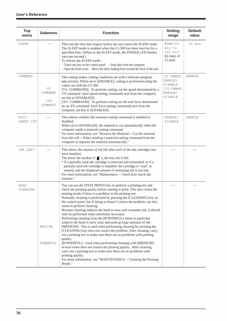
76
User's Reference
Defaultvalue
Settingrange
FunctionSubmenuTopmenu
— — —INK LEFT This shows the amount of ink left after each of the ink cartridges hasbeen installed.The fewer the markers (" "), the less ink is left.* If a partially used ink cartridge is removed and reinstalled, or if a
partially used ink cartridge is installed, the cartridge is "read" asunused, and the displayed amount of remaining ink is not true.
For more information, see "Maintenance -- Check how much inkremains."
COMMAND
VSCOMMAND
!FSCOMMAND
[VS COMMAND]ENABLE/DISABLE[!FS COMMAND]ENABLE/DISABLE
ENABLEThis setting makes cutting conditions set with a software programtake priority. When set to [DISABLE], cutting is performed using thevalues set with the CJ-500.[VS COMMAND]: To perform cutting, set the speed determined by aVS command (tool speed setting command) sent from the computer,set this to [ENABLED].[!FS COMMAND]: To perform cutting set the tool force determinedby an !FS command (tool force setting command) sent from thecomputer, set this to [ENABLED].
SLEEP 15 minThis sets the time that elapses before the unit enters the SLEEP mode.The SLEEP mode is enabled when the CJ-500 has been inactive for aspecified time. (When in the SLEEP mode, the POWER LED flashesonce per second.)To release the SLEEP mode... - Touch any key on the control panel. - Send data from the computer. - Open the front cover. - Move the sheet loading lever toward the back of the unit.
— NONE/15min to120 min(In steps of15 min)
AUTOSHEET CUT
— ENABLE/DISABLE
ENABLEThis selects whether the material-cutting command is enabled ordisabled.When set to [ENABLED], the material is cut automatically when thecomputer sends a material-cutting command.For more information, see "Remove the Material -- Cut the materialfrom the roll -- When sending a material-cutting command from thecomputer to separate the material automatically."
HEADCLEANING
MEDIUM
POWERFUL
— —You can use the [TEST PRINT] key to perform a printing test andcheck the printing quality before starting to print. This also cleans theprinting heads if there is a problem in the printing test.Normally cleaning is performed by pressing the [CLEANING] key onthe control panel, but if doing so doesn’t correct the problem, use thismenu to perform cleaning.Because cleaning subjects the head to wear and consumes ink, it shouldonly be performed when absolutely necessary.Performing cleaning from the [POWERFUL] menu in particularsubjects the head to early wear and used up large amounts of ink.[MEDIUM]: This is used when performing cleaning by pressing the[CLEANING] key does not correct the problem. After cleaning, carryout a printing test to make sure there are no problems with printingquality.[POWERFUL]: Used when performing cleaning with [MEDIUM]several times does not restore the printing quality. After cleaning,carry out a printing test to make sure there are no problems withprinting quality.For more information, see "MAINTENANCE -- Cleaning the PrintingHeads."

77
User's Reference
For details about each of the menus, see the "Description of Display Menus."
Selecting the language for screen messages
Display Menus Flowchart
Load the material and press
key
When the power is turned on for the first time, or turned on after removing the ink
Roland CJ-500 Ver.1.00
SETUP SHEETROLL EDGE PIECE
Roland CJ-500PIGMENT CMYKLcLm
MENU LANGUAGEENGLISH
MENU LANGUAGEJAPANESE
SETUP SHEETROLL
If [EDGE SENSE] is [DISABLE].
Press the [BASE POINT] key
AUTO CROP MARKBASE
PRESS SETUP KEY
Press the key
Printing/cutting area of the loaded material (length).*This is not displayed when [ROLL] or [EDGE] has been selected.
Printing/cutting areaof the loaded material(width).
W1000mm L1230mmFINE BI-DIR
The settings for [PRINT MODE] (Print Direction) display only in the case of [BI-DIRECTION].
NOW PROCESSING..
Settings for [PRINT MODE] (Print Mode)PHOTO/SUPER/FINE/FINE2/NORMAL/FAST/DRAFT
Top menu
Press the
Press the [ENTER] key to enable the setting.
Use or to select.
Attach the drain bottle, and press [ENTER] key.
The system will execute ink fill.
No ink is filled.
Select the installed ink type and press the [ENTER] key.
SELECT INK TYPEPIG.CMYKLcLm
NOW FILLING INK
Roland CJ-500UNKNOWN INK TYPE
PIG. CMYKLcLm/PIG. CMYKOrGr/DYE CMYKLcLm
INSTALL DRAIN BOTTLE
the key
Press the [ENTER] key to enable the setting.
Use or to select.
+
Choose [BASE] or [BASE-ALIGN], then press the [ENTER] key

78
User's Reference
PRINT & CUT/PRINT/CUT
MENUDEMO
DEMO PRINT & CUT
BIDIRECTIONADJUST
BIDIRECTIONTEST PRINT
MENUBIDIRECTION
-15 to +15 (In steps of 1)
ADJUST +0 +0
NONE/ 2 / 3
MENUOVER PRINT
OVER PRINT NONE 2
MENUFACTORY DEFAULT
FACTORY DEFAULTNOW PROCESSING..
• Move to the previous menu screen or the next menu screen• Select the value for a setting• Moves the material (when specifying the printing/cutting location)
• Move to a submenu screen• Moves the carriage (when specifying the printing/cutting location)
• Move to the previous menu screen• Moves the carriage (when specifying the printing/cutting location)
• Executes the menu• Locks in the value for a setting
MENUCALIBRATION
CALIBRATIONPRINTING ADJ.
PRINTING ADJ.ADJUST
PRINTING ADJ.TEST PRINT
ADJUST+0.25% +0.30%
CALIBRATIONCUTTING ADJ.
CUTTING ADJ.FEED ADJUST
FEED ADJUST+0.00% +0.00%
CUTTING ADJ.SCAN ADJUST
SCAN ADJUST+0.00% +0.00%
NONE/ 10 to 990 (In steps of 10 sec.)
MENUDRYING TIME
DRYING TIME15sec 15sec
ENABLE/DISABLE
MENUEDGE SENSE
EDGE SENSEENABLE DISABLE
ENABLE/DISABLE
MENUCROP MARK
CROP MARKENABLE DISABLE
NONE/ 10 to 990 (In steps of 10 sec.)
MENUTIME OUT
TIME OUT15sec 15sec
PRINT-CUT ADJ.MANUAL
PRINT-CUT ADJ.AUTO
MENUPRINT-CUT ADJ.
MOVE CURDOR AND PRESS ENTER
NOW PROCESSING..
Press the key
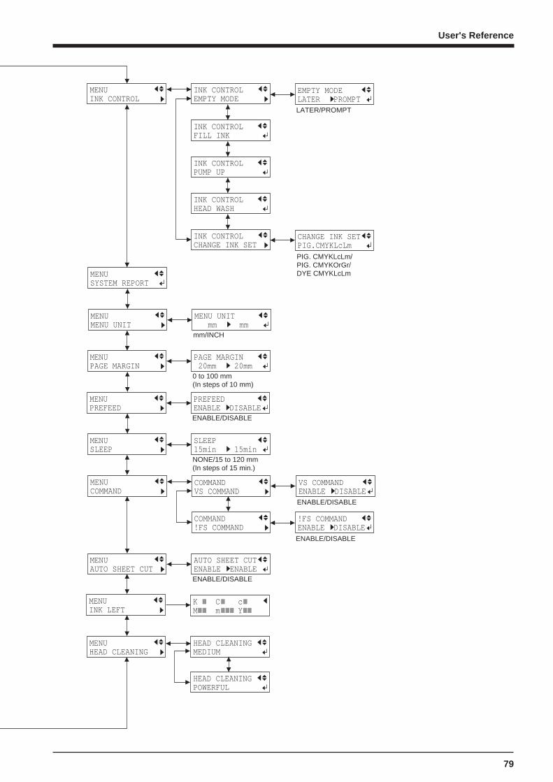
79
User's Reference
LATER/PROMPT
EMPTY MODELATER PROMPT
MENUHEAD CLEANING
HEAD CLEANINGMEDIUM
MENUINK CONTROL
INK CONTROLEMPTY MODE
INK CONTROLFILL INK
INK CONTROLPUMP UP
INK CONTROLCHANGE INK SET
PIG. CMYKLcLm/PIG. CMYKOrGr/DYE CMYKLcLm
INK CONTROLHEAD WASH
CHANGE INK SETPIG.CMYKLcLm
NONE/15 to 120 mm (In steps of 15 min.)
MENUSLEEP
SLEEP15min 15min
ENABLE/DISABLE
MENUAUTO SHEET CUT
AUTO SHEET CUTENABLE ENABLE
0 to 100 mm (In steps of 10 mm)
MENUPAGE MARGIN
PAGE MARGIN 20mm 20mm
mm/INCH
MENUMENU UNIT
MENU UNIT mm mm
MENUINK LEFT
MENUSYSTEM REPORT
ENABLE/DISABLE
MENUPREFEED
PREFEEDENABLE DISABLE
COMMAND!FS COMMAND
MENUCOMMAND
COMMANDVS COMMAND
!FS COMMANDENABLE DISABLE
VS COMMANDENABLE DISABLE
HEAD CLEANINGPOWERFUL
ENABLE/DISABLE
ENABLE/DISABLE
K C cM m Y
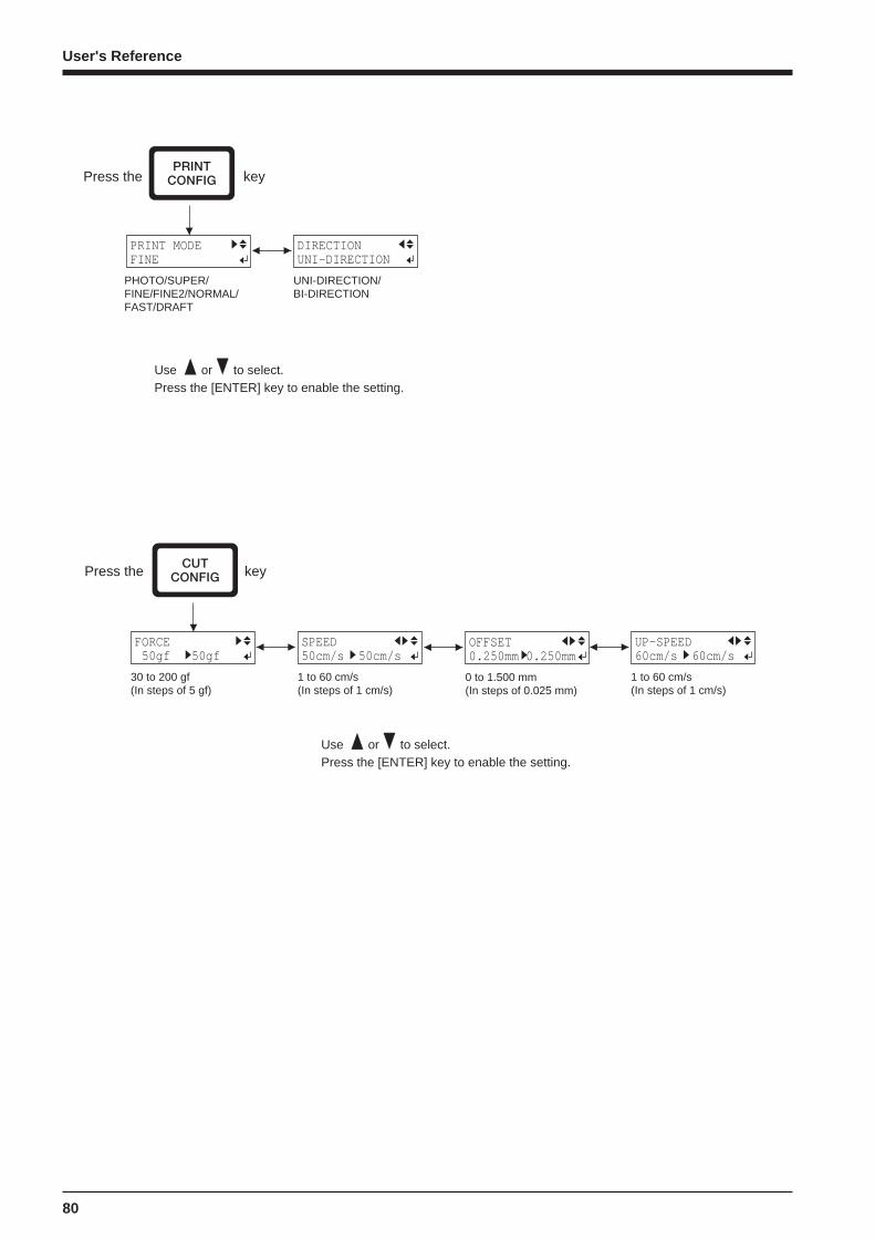
80
User's Reference
FORCE 50gf 50gf
30 to 200 gf (In steps of 5 gf)
1 to 60 cm/s(In steps of 1 cm/s)
SPEED50cm/s 50cm/s
OFFSET0.250mm 0.250mm
1 to 60 cm/s(In steps of 1 cm/s)
UP-SPEED60cm/s 60cm/s
0 to 1.500 mm(In steps of 0.025 mm)
Press the key
Press the [ENTER] key to enable the setting.Use or to select.
PRINT MODEFINE
PHOTO/SUPER/FINE/FINE2/NORMAL/FAST/DRAFT
UNI-DIRECTION/BI-DIRECTION
DIRECTION UNI-DIRECTION
Press the key
Press the [ENTER] key to enable the setting.Use or to select.
81
User's Reference
Top menu
W1234mm L ---mmFINE BI-DIR
What to Do If...
If the CJ-500 doesn't run...
Is the power cord connected correctly?
Connect the power cord included with the CJ-500 to the unit, and plug the other end securely into an electrical outlet. (See “Unpackingthe CAMMJET -- 2 -- Setting Up and Connection” .)
Is the CJ-500 power on?
Turn on the power. (See “Unpacking the CAMMJET-- 5 -- Power up” .)
Has material been loaded (the SETUP LED is lighted)?
If the SETUP LED is not illuminated, make sure the material is loaded correctly and press the [SETUP] key to illuminate the SETUPLED.
Is the PAUSE LED lighted?
If the [PAUSE] key has been pressed and the PAUSE LED is lighted, the unit has been paused.To resume printing or cutting, press the [PAUSE] key again. The PAUSE LED is extinguished, and printing or cutting resumes.To terminate printing or cutting, first stop the transmission of printing or cutting instructions from the computer to the CJ-500. Thenpress the [SETUP] key. Hold down for about 1 second. This deletes the printing or cutting instructions that have already been sent fromthe computer to the CJ-500, and printing or cutting is stopped.
Is the top menu displayed?
If the top menu isn't displayed, printing doesn't start even when data is sent from the computer.
Conditions for starting printing or cuttingThe material must be already set up (with the SETUP LED lighted),and the display must show the top menu.
If another menu screen is displayed, press the [SETUP] key to go back to the top menu.(Pressing the [SETUP] key when another menu screen is displayed does not cancel the set-up for the material.)
Are the computer and the CJ-500 linked with the right cable ?
The type of cable you need is determined by your computer. The cable which matches the model of computer being used shouldbe selected.
Is the cable making a secure connection?
Connect securely. (See “Unpacking the CAMMJET -- 2 -- Setting Up and Connection” .)
Has the correct driver selection been made for the application software?
Select the appropriate CJ-500 driver.
82
User's Reference
If the "INK EMPTY" message appears during setupA cartridge has run out of ink, and printing cannot be started.If printing data is being sent, this message is displayed and the printer chirps. At the same time, operation is paused and the PAUSELED flashes. Replace the empty cartridge with a new one and press the [PAUSE] key to start printing.
Printed Output is Unacceptable
If drop-out occurs with printed images.
Clean the printing heads (see "Maintenance -- Cleaning the Printing Heads").
Is the surface of the platen dirty or scratched?
Clean the platen (see “Maintenance -- When the Product Needs Cleaning”).
Is the material dirty?
Remove superficial soiling, then load the material.
Is the material damaged?
Clean, attractive printing is not possible if the material is damaged or warped.Use care to keep materials from being damaged while in storage.
During printing, was the front cover opened (executing an emergency stop) or the [PAUSE] key pressed?
If operation is stopped or paused while printing is in progress, the quality of the image before and after the interruption may differ. It is agood idea to avoid pausing operation while printing is in progress whenever possible.
Is thick material in use, or does the surface of the material rub against the printing heads?
If material feed is not smooth because the material catches on the head, then adjust the height of the printing heads (see "User's Refer-ence -- Adjusting the Height of the Printing Head").When the height of the printing head has been adjusted, it is necessary to perform bidirectional correction (only when the printingdirection for [PRINT MODE] has been set to [BI-DIRECTION]). For more information about bidirectional correction, see "User'sReference -- Making Corrections for Printing -- Bidirectional Correction."
If the type of material was changed, was feed correction performed?
Correcting the amount of feed improves the dot-positioning accuracy in the feed direction, which can help enhance image quality.If the type of material was changed, refer to "User's Reference -- Making Corrections for Printing -- Feed Correction" and performcorrection for feed.
Printing goes beyond the loaded material
Has the material been loaded at an angle?
If the loaded material is not straight, it may extend outside the printing area.In “Setup for Printing” or “Setup for Cutting,” refer to “1 Loading the Material” and load the material correctly.
83
User's Reference
The Material is not cut properly
Are the blade and blade holder installed correctly and securely?
Install these so that there is no looseness (see “Setup for Cutting -- Installing the Cutter”).
Is the blade chipped?
If it is, replace it with a new one (see “Maintenance -- Replacing the Cutter Blade”).
Check if there are any dirty deposits on the blade.
If dirty, remove and clean the blade.
Make sure you are using an appropriate cutter force setting.
Perform a “test cut,” then adjust to the optimum cutter force (see “Setup for Cutting -- Test Cutting”).
Material feed is not smooth (slippage occurs)
Is thick material being used?
If the surface of the material rubs against the printing heads and smooth feed is impossible, then adjust the height of the printing heads(see "User's Reference -- Adjusting the Height of the Printing Head").When the height of the printing head has been adjusted, it is necessary to perform bidirectional correction (only when the printingdirection for [PRINT MODE] has been set to [BI-DIRECTION]). For more information about bidirectional correction, see "User'sReference -- Making Corrections for Printing -- Bidirectional Correction."
Does a piece of flat material touch the shaft or roll material at the back of the machine?
When loading flat material, if the material touches the shaft or roll material at the back of the machine, remove the shaft and roll material.If the material touches an obstruction while printing is in progress, normal material feed is not performed, and image quality may sufferor the material may jam.
Is the sheet material loaded at an angle? Are the left and right edges of the material not straight?
If the material is loaded at an angle or if the left and right sides of the material are not cut straight, the location of the edges may shift asfeed is carried out. This may cause the material to rub against the inner side of the CJ-500 or be displaced from the printing/cutting area.
Is the roll material loaded correctly?
If the roll material is not loaded correctly, the material may come loose or advance at an angle. In “Setup for Printing” or “Setup forCutting,” refer to “1 Loading the Material” and load the material correctly.
Has the sheet loading lever been moved all the way to “LOAD?”
If the sheet loading lever is moved only part of the way, only the right-hand pinch roller is not lowered. Make sure the left- and right-hand pinch rollers are inside the edges of the material then move the level all the way to “LOAD.”
If the material is to be advanced over a long distance,
Movable pinch roller inward slightly can help prevent the material from becoming dislodged.
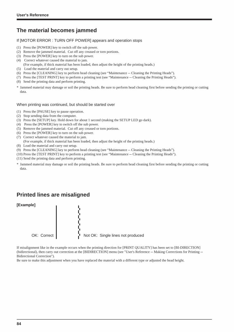
84
User's Reference
The material becomes jammed
If [MOTOR ERROR : TURN OFF POWER] appears and operation stops
(1) Press the [POWER] key to switch off the sub power.(2) Remove the jammed material. Cut off any creased or torn portions.(3) Press the [POWER] key to turn on the sub power.(4) Correct whatever caused the material to jam.
(For example, if thick material has been loaded, then adjust the height of the printing heads.)(5) Load the material and carry out setup.(6) Press the [CLEANING] key to perform head cleaning (see “Maintenance -- Cleaning the Printing Heads”).(7) Press the [TEST PRINT] key to perform a printing test (see “Maintenance -- Cleaning the Printing Heads”).(8) Send the printing data and perform printing.
* Jammed material may damage or soil the printing heads. Be sure to perform head cleaning first before sending the printing or cuttingdata.
When printing was continued, but should be started over
(1) Press the [PAUSE] key to pause operation.(2) Stop sending data from the computer.(3) Press the [SETUP] key. Hold down for about 1 second (making the SETUP LED go dark).(4) Press the [POWER] key to switch off the sub power.(5) Remove the jammed material. Cut off any creased or torn portions.(6) Press the [POWER] key to turn on the sub power.(7) Correct whatever caused the material to jam.
(For example, if thick material has been loaded, then adjust the height of the printing heads.)(8) Load the material and carry out setup.(9) Press the [CLEANING] key to perform head cleaning (see “Maintenance -- Cleaning the Printing Heads”).(10) Press the [TEST PRINT] key to perform a printing test (see “Maintenance -- Cleaning the Printing Heads”).(11) Send the printing data and perform printing.
* Jammed material may damage or soil the printing heads. Be sure to perform head cleaning first before sending the printing or cuttingdata.
Printed lines are misaligned
[Example]
OK: Correct Not OK: Single lines not produced
If misalignment like in the example occurs when the printing direction for [PRINT QUALITY] has been set to [BI-DIRECTION](bidirectional), then carry out correction at the [BIDIRECTION] menu (see "User's Reference -- Making Corrections for Printing --Bidirectional Correction").Be sure to make this adjustment when you have replaced the material with a different type or adjusted the head height.
85
User's Reference
The material cannot be separated
Is a blade installed in the separating knife?
If no blade is installed, then install one (see "Maintenance -- How to Replace the Separating Knife").
Is the blade dull or broken?
If the blade has become dull or broken, replace it with the replacement blade included with the unit (see "Maintenance -- How to Replacethe Separating Knife").
* Some materials cannot be separated due to their composition.
The material cannot be separated automatically
Has the [AUTO SHEET CUT] menu item been set to [ENABLE]?
If the material-cutting command has been set to "enable" with the driver, then set [AUTO SHEET CUT] on the CJ-500 to [ENABLE](see "Remove the Material -- Cut the material from the roll").
Has the material-cutting command been set to "enable" with the driver?
When the material-cutting command has not been set to "enable" with the driver, automatic separation of the material is not performed,even when [AUTO SHEET CUT] has been set to [ENABLE].
Adjustment of the printing and cutting positions was performed (automati-cally), but the positions are not aligned
Depending on the type of material, automatic detection of crop marks may not be possible.In such cases, perform the alignment manually (see "Adjusting the Printing and Cutting Positions_Adjusting Manually").
Automatic setting of the base point and the align point was performed, butthe positions are not aligned
Depending on the type of material and lamination performed, automatic detection of crop marks may not be possible.In such cases, set the base point and align point manually (see "Remove the Printed Material, then Reload the Material and PerformCutting -- Adjusting Manually").
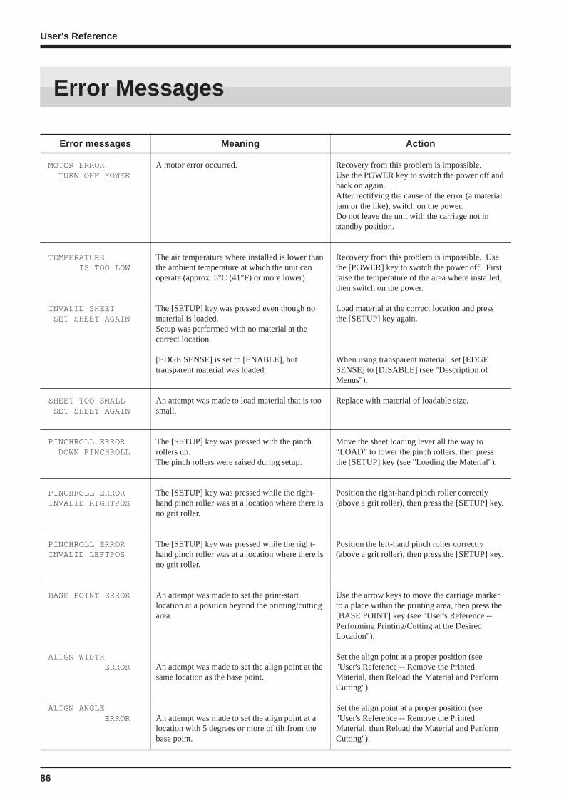
86
User's Reference
Meaning
A motor error occurred.
The air temperature where installed is lower thanthe ambient temperature at which the unit canoperate (approx. 5°C (41°F) or more lower).
The [SETUP] key was pressed even though nomaterial is loaded.Setup was performed with no material at thecorrect location.
[EDGE SENSE] is set to [ENABLE], buttransparent material was loaded.
An attempt was made to load material that is toosmall.
The [SETUP] key was pressed with the pinchrollers up.The pinch rollers were raised during setup.
The [SETUP] key was pressed while the right-hand pinch roller was at a location where there isno grit roller.
The [SETUP] key was pressed while the right-hand pinch roller was at a location where there isno grit roller.
An attempt was made to set the print-startlocation at a position beyond the printing/cuttingarea.
An attempt was made to set the align point at thesame location as the base point.
An attempt was made to set the align point at alocation with 5 degrees or more of tilt from thebase point.
Action
Recovery from this problem is impossible.Use the POWER key to switch the power off andback on again.After rectifying the cause of the error (a materialjam or the like), switch on the power.Do not leave the unit with the carriage not instandby position.
Recovery from this problem is impossible. Usethe [POWER] key to switch the power off. Firstraise the temperature of the area where installed,then switch on the power.
Load material at the correct location and pressthe [SETUP] key again.
When using transparent material, set [EDGESENSE] to [DISABLE] (see "Description ofMenus").
Replace with material of loadable size.
Move the sheet loading lever all the way to“LOAD” to lower the pinch rollers, then pressthe [SETUP] key (see "Loading the Material").
Position the right-hand pinch roller correctly(above a grit roller), then press the [SETUP] key.
Position the left-hand pinch roller correctly(above a grit roller), then press the [SETUP] key.
Use the arrow keys to move the carriage markerto a place within the printing area, then press the[BASE POINT] key (see "User's Reference --Performing Printing/Cutting at the DesiredLocation").
Set the align point at a proper position (see"User's Reference -- Remove the PrintedMaterial, then Reload the Material and PerformCutting").
Set the align point at a proper position (see"User's Reference -- Remove the PrintedMaterial, then Reload the Material and PerformCutting").
Error messages
MOTOR ERROR TURN OFF POWER
TEMPERATURE IS TOO LOW
INVALID SHEET SET SHEET AGAIN
SHEET TOO SMALL SET SHEET AGAIN
PINCHROLL ERROR DOWN PINCHROLL
PINCHROLL ERRORINVALID RIGHTPOS
PINCHROLL ERRORINVALID LEFTPOS
BASE POINT ERROR
ALIGN WIDTH ERROR
ALIGN ANGLE ERROR
Error Messages

87
User's Reference
Meaning
- With [PRINT-CUT ADJ.] set to [AUTO], cropmarks cannot be detected.
- The [BASE POINT] key was pressed duringmaterial setup to make the setting for auto-matic detection of crop marks, but crop markscannot be detected.
An attempt was made to perform a printing orcutting test outside the printing or cutting area.
The main power switch was turned off withoutfirst turning off the sub power with the[POWER] key.
Action
Load the material at the correct position andperform detection of crop marks again.
Perform the printing or cutting test inside theprinting or cutting area.
Press the [POWER] key to turn off the subpower, then turn on the power again.
Error messages
CROPMARK ERROR NOT FOUND
CURSOR POS. ERROR OUT OF AREA
ILLEGAL SHUTDOWN TURN OFF POWER
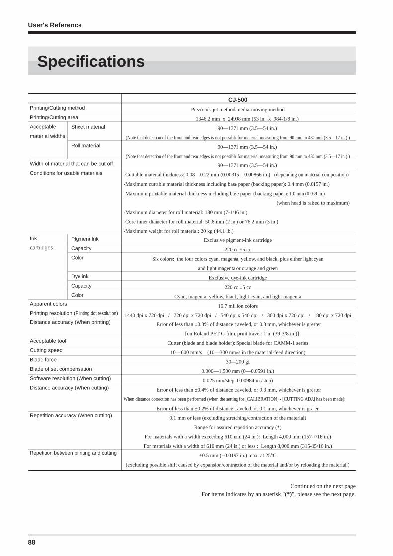
88
User's Reference
CJ-500
Piezo ink-jet method/media-moving method
1346.2 mm x 24998 mm (53 in. x 984-1/8 in.)
90—1371 mm (3.5—54 in.)
(Note that detection of the front and rear edges is not possible for material measuring from 90 mm to 430 mm (3.5—17 in.).)
90—1371 mm (3.5—54 in.)
(Note that detection of the front and rear edges is not possible for material measuring from 90 mm to 430 mm (3.5—17 in.).)
90—1371 mm (3.5—54 in.)
-Cuttable material thickness: 0.08—0.22 mm (0.00315—0.00866 in.) (depending on material composition)
-Maximum cuttable material thickness including base paper (backing paper): 0.4 mm (0.0157 in.)
-Maximum printable material thickness including base paper (backing paper): 1.0 mm (0.039 in.)
(when head is raised to maximum)
-Maximum diameter for roll material: 180 mm (7-1/16 in.)
-Core inner diameter for roll material: 50.8 mm (2 in.) or 76.2 mm (3 in.)
-Maximum weight for roll material: 20 kg (44.1 lb.)
Exclusive pigment-ink cartridge
220 cc ±5 cc
Six colors: the four colors cyan, magenta, yellow, and black, plus either light cyan
and light magenta or orange and green
Exclusive dye-ink cartridge
220 cc ±5 cc
Cyan, magenta, yellow, black, light cyan, and light magenta
16.7 million colors
1440 dpi x 720 dpi / 720 dpi x 720 dpi / 540 dpi x 540 dpi / 360 dpi x 720 dpi / 180 dpi x 720 dpi
Error of less than ±0.3% of distance traveled, or 0.3 mm, whichever is greater
[on Roland PET-G film, print travel: 1 m (39-3/8 in.)]
Cutter (blade and blade holder): Special blade for CAMM-1 series
10—600 mm/s (10—300 mm/s in the material-feed direction)
30—200 gf
0.000—1.500 mm (0—0.0591 in.)
0.025 mm/step (0.00984 in./step)
Error of less than ±0.4% of distance traveled, or 0.3 mm, whichever is greater
When distance correction has been performed (when the setting for [CALIBRATION] - [CUTTING ADJ.] has been made):
Error of less than ±0.2% of distance traveled, or 0.1 mm, whichever is grater
0.1 mm or less (excluding stretching/contraction of the material)
Range for assured repetition accuracy (*)
For materials with a width exceeding 610 mm (24 in.): Length 4,000 mm (157-7/16 in.)
For materials with a width of 610 mm (24 in.) or less : Length 8,000 mm (315-15/16 in.)
±0.5 mm (±0.0197 in.) max. at 25°C
(excluding possible shift caused by expansion/contraction of the material and/or by reloading the material.)
Pigment ink
Capacity
Color
Dye ink
Capacity
Color
Printing/Cutting method
Printing/Cutting area
Acceptable
material widths
Width of material that can be cut off
Conditions for usable materials
Ink
cartridges
Apparent colors
Printing resolution (Printing dot resolution)
Distance accuracy (When printing)
Acceptable tool
Cutting speed
Blade force
Blade offset compensation
Software resolution (When cutting)
Distance accuracy (When cutting)
Repetition accuracy (When cutting)
Repetition between printing and cutting
Specifications
Sheet material
Roll material
Continued on the next pageFor items indicates by an asterisk "(*) ", please see the next page.
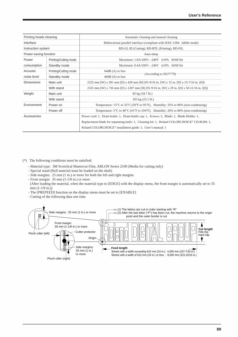
89
User's Reference
Printing heads cleaning
Interface
Instruction system
Power-saving function
Power
consumption
Acoustic
noise level
Dimensions
Weight
Environment
Accessories
Automatic cleaning and manual cleaning
Bidirectional parallel interface (compliant with IEEE 1284: nibble mode)
RD-GL III (Cutting), RD-RTL (Printing), RD-PJL
Auto-sleep
Maximum: 1.0A/100V—240V ±10% 50/60 Hz
Maximum: 0.4A/100V—240V ±10% 50/60 Hz
64dB (A) or less
40dB (A) or less
2325 mm [W] x 381 mm [D] x 428 mm [H] (91-9/16 in. [W] x 15 in. [D] x 15-7/16 in. [H])
2325 mm [W] x 736 mm [D] x 1287 mm [H] (91-9/16 in. [W] x 29 in. [D] x 50-11/16 in. [H])
85 kg (18.7 lb.)
105 kg (23.1 lb.)
Temperature: 15°C to 35°C (59°F to 95°F), Humidity: 35% to 80% (non-condensing)
Temperature: 5°C to 40°C (41°F to 104°F), Humidity: 20% to 80% (non-condensing)
Power cord: 1, Drain bottle: 1, Drain-bottle cap: 1, Screws: 2, Blade: 1, Blade Holder: 1,
Replacement blade for separating knife: 1, Cleaning kit: 1, Roland COLORCHOICE® CD-ROM: 1,
Roland COLORCHOICE® installation guide: 1, User’s manual: 1
(*) The following conditions must be satisfied:
- Material type: 3M Scotchcal Mastercut Film, ARLON Series 2100 (Media for cutting only)- Special stand (Roll material must be loaded on the shaft)- Side margins: 25 mm (1 in.) or more for both the left and right margins- Front margin: 35 mm (1-1/8 in.) or more (After loading the material, when the material type to [EDGE] with the display menu, the front margin is automatically set to 35mm (1-1/8 in.))
- The [PREFEED] function on the display menu must be set to [ENABLE]- Cutting of the following data one time
Origin
(1) The letters are cut in order starting with "R"(2) After the last letter ("P") has been cut, the machine returns to the origin point and the outer border is cut
Feed lengthSheets with a width exceeding 610 mm (24 in.): 4,000 mm (157-7/16 in.)Sheets with a width of 610 mm (24 in.) or less : 8,000 mm (315-15/16 in.)
Cut lengthFills the hard clip
Front margin: 35 mm (1-1/8 in.) or more
Side margins: 25 mm (1 in.) or more
Side margins: 25 mm (1 in.) or more
Pinch roller (left)
Pinch roller (right)
Cutter protector
Printing/Cutting mode
Standby mode
Printing/Cutting mode
Standby mode
Main unit
With stand
Main unit
With stand
Power on
Power off
(According to ISO7779)
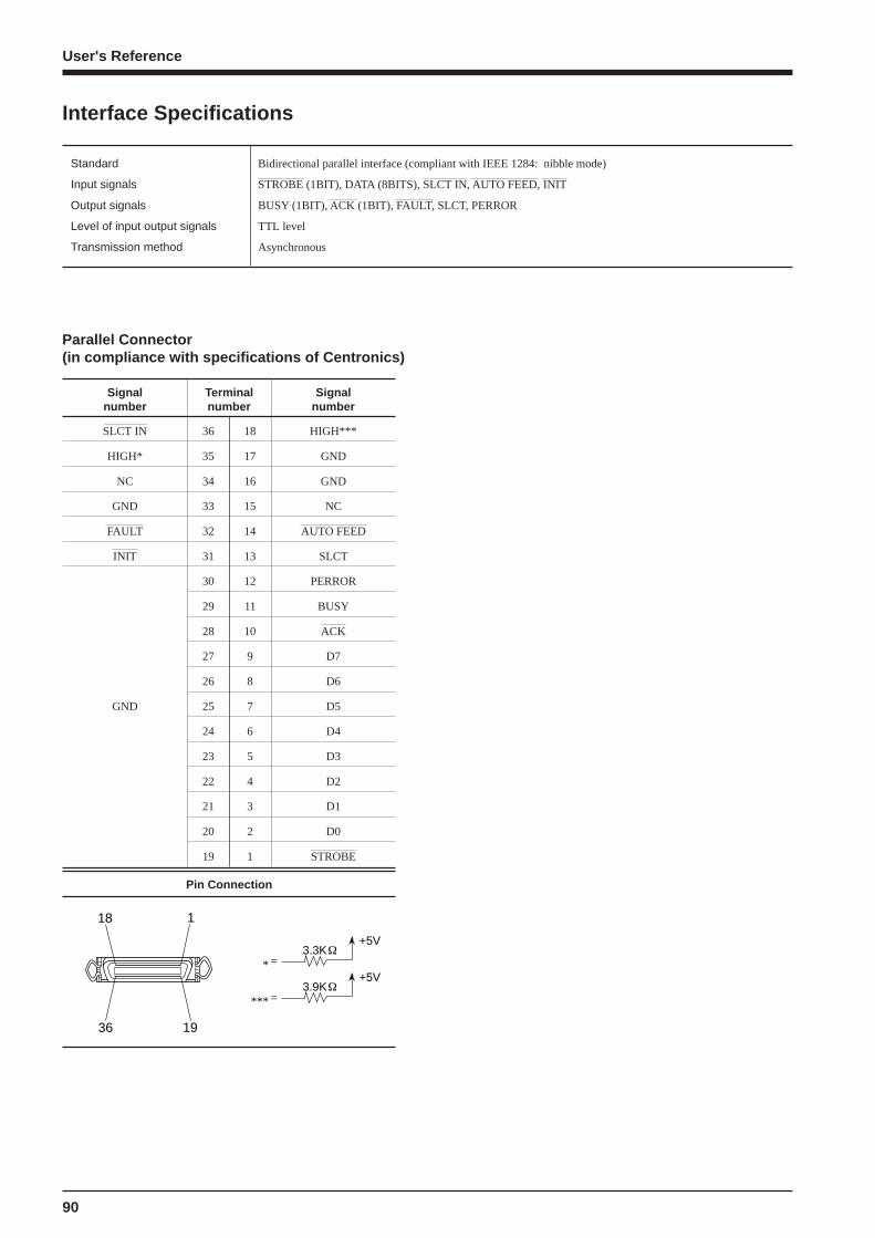
90
User's Reference
SLCT IN
HIGH*
NC
GND
FAULT
INIT
GND
36
35
34
33
32
31
30
29
28
27
26
25
24
23
22
21
20
19
18
17
16
15
14
13
12
11
10
9
8
7
6
5
4
3
2
1
HIGH***
GND
GND
NC
AUTO FEED
SLCT
PERROR
BUSY
ACK
D7
D6
D5
D4
D3
D2
D1
D0
STROBE
Interface Specifications
Parallel Connector(in compliance with specifications of Centronics)
Signalnumber
Signalnumber
Terminalnumber
Pin Connection
1
19
18
36
3.3K+5V
=*
3.9K+5V
=***
Standard Bidirectional parallel interface (compliant with IEEE 1284: nibble mode)
Input signals STROBE (1BIT), DATA (8BITS), SLCT IN, AUTO FEED, INIT
Output signals BUSY (1BIT), ACK (1BIT), FAULT, SLCT, PERROR
Level of input output signals TTL level
Transmission method Asynchronous

R2-991015