Embed Size (px)
Citation preview
7/29/2019 CJ Install Guide July2012
http://slidepdf.com/reader/full/cj-install-guide-july2012 1/4
Page 1 of 4
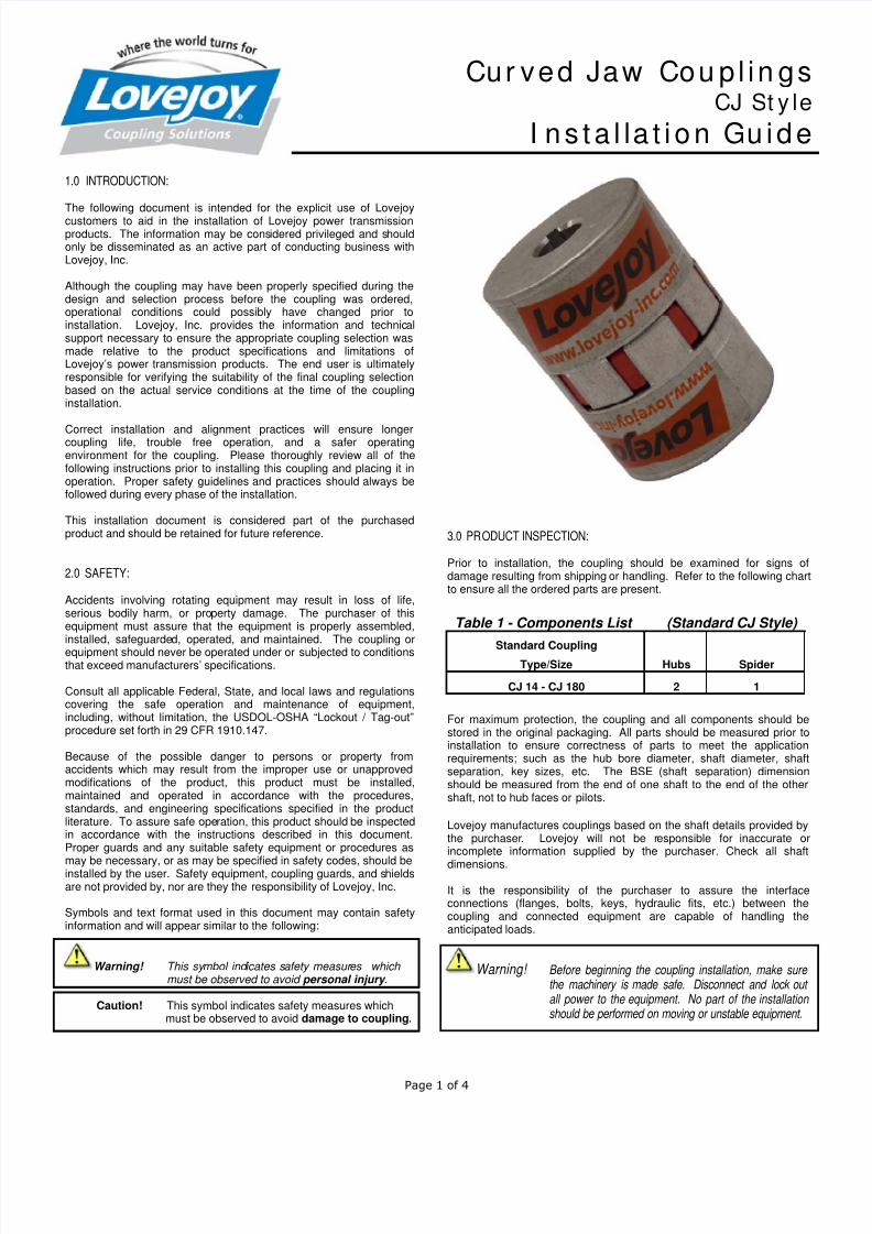
Cur ved Jaw Cou p l in gsCJ St y le
I ns ta l la t i on Gu ide
1.0 INTRODUCTION:
The following document is intended for the explicit use of Lovejoy
customers to aid in the installation of Lovejoy power transmissionproducts. The information may be considered privileged and shouldonly be disseminated as an active part of conducting business withLovejoy, Inc.
Although the coupling may have been properly specified during thedesign and selection process before the coupling was ordered,operational conditions could possibly have changed prior toinstallation. Lovejoy, Inc. provides the information and technicalsupport necessary to ensure the appropriate coupling selection wasmade relative to the product specifications and limitations ofLovejoy’s power transmission products. The end user is ultimatelyresponsible for verifying the suitability of the final coupling selectionbased on the actual service conditions at the time of the couplinginstallation.
Correct installation and alignment practices will ensure longercoupling life, trouble free operation, and a safer operatingenvironment for the coupling. Please thoroughly review all of thefollowing instructions prior to installing this coupling and placing it inoperation. Proper safety guidelines and practices should always befollowed during every phase of the installation.
This installation document is considered part of the purchasedproduct and should be retained for future reference.
2.0 SAFETY:
Accidents involving rotating equipment may result in loss of life,serious bodily harm, or property damage. The purchaser of thisequipment must assure that the equipment is properly assembled,installed, safeguarded, operated, and maintained. The coupling or
equipment should never be operated under or subjected to conditionsthat exceed manufacturers’ specifications.
Consult all applicable Federal, State, and local laws and regulationscovering the safe operation and maintenance of equipment,including, without limitation, the USDOL-OSHA “Lockout / Tag-out”procedure set forth in 29 CFR 1910.147.
Because of the possible danger to persons or property fromaccidents which may result from the improper use or unapprovedmodifications of the product, this product must be installed,maintained and operated in accordance with the procedures,standards, and engineering specifications specified in the productliterature. To assure safe operation, this product should be inspectedin accordance with the instructions described in this document.Proper guards and any suitable safety equipment or procedures as
may be necessary, or as may be specified in safety codes, should beinstalled by the user. Safety equipment, coupling guards, and shieldsare not provided by, nor are they the responsibility of Lovejoy, Inc.
Symbols and text format used in this document may contain safetyinformation and will appear similar to the following:
Warning! This symbol indicates safety measures which must be observed to avoid personal injury .
Caution! This symbol indicates safety measures whichmust be observed to avoid damage to coupling.
3.0 PRODUCT INSPECTION:
Prior to installation, the coupling should be examined for signs ofdamage resulting from shipping or handling. Refer to the following chartto ensure all the ordered parts are present.
For maximum protection, the coupling and all components should bestored in the original packaging. All parts should be measured prior toinstallation to ensure correctness of parts to meet the applicationrequirements; such as the hub bore diameter, shaft diameter, shaftseparation, key sizes, etc. The BSE (shaft separation) dimensionshould be measured from the end of one shaft to the end of the othershaft, not to hub faces or pilots.
Lovejoy manufactures couplings based on the shaft details provided bythe purchaser. Lovejoy will not be responsible for inaccurate orincomplete information supplied by the purchaser. Check all shaft
dimensions.
It is the responsibility of the purchaser to assure the interfaceconnections (flanges, bolts, keys, hydraulic fits, etc.) between thecoupling and connected equipment are capable of handling theanticipated loads.
Warning! Before beginning the coupling installation, make sure the machinery is made safe. Disconnect and lock out all power to the equipment. No part of the installation should be performed on moving or unstable equipment.
Table 1 - Components List (Standard CJ Style)
Standard CouplingType/Size Hubs Spider
CJ 14 - CJ 180 2 1
7/29/2019 CJ Install Guide July2012
http://slidepdf.com/reader/full/cj-install-guide-july2012 2/4
Page 2 of 4
Lov ejoy , I nc .
Wor ld H eadqua r te r s
2655 Wisconsin AvenueDowners Grove, IL 60515630-852-0500630-852-2120 [email protected]
w w w . lo v e j o y - i n c. co m
ISO 9001-2008 Certified
Version Date: 24-July-2012
4.0 REQUIRED TOOLS:
Calibrated Torque Wrench and Allen sockets Alignment Equipment (dial indicator, laser, straight edge) Appropriate tooling for repositioning equipment
5.0 COUPLING AND COMPONENT PREPARATION:
5.1 All exposed surfaces of the coupling and components,including hubs, spiders, spacers, collars, and any other Lovejoy
supplied subassemblies should be thoroughly cleaned prior toinstallation to remove any protective coatings that may have beenapplied by Lovejoy as corrosion protection for the coupling surfacesduring shipping. All coupling parts, equipment components, shafts,and keyways must be clean and free of any foreign materials prior toattempting assembly or installation. A clean cloth dampened with anonflammable solvent should be sufficient for this cleaning.
5.2 All hub bores, shafts, keys, and keyways must be checked forraised metal, nicks, burrs, dents, gouges, etc., and should be dressedor repaired accordingly prior to installation.
5.3 Prior to removing any existing coupling, establish and recordthe Distance Between Shaft Ends (BSE), or Gap (G) between thedriver and driven and compare this value with the ‘G’ dimension forLovejoy Curved Jaw Couplings in Table-4 to verify fit of the coupling.
5.4 Once all necessary measurements have been taken and allcomponents are verified as correct, remove any existing coupling anddress the shafts on the driver and driven equipment.
5.5 If the actual shaft BSE is the same as the specified gap forthe Lovejoy Curved Jaw coupling (see Table-4), then the hubs can bemounted flush with the ends of the driver and driven shafts.
5.6 If the actual shaft BSE is different than the specified gap forthe Lovejoy Curved Jaw coupling, then the hubs must be mounted onthe driver and driven shafts so that the dimension between the hubfaces matches the ‘G’ dimension, or gap as specified in Table-4.
5.7 Lovejoy machines the bore in all Lovejoy Curved Jaw stylehubs with ‘inch’ dimensioned straight bores and keyways to meetthe industry accepted ANSI/AGMA 9002-B04 Standards’ tolerance
for common keyways and clearance fit bores unless otherwisespecified. Tapered and spline bores may require specialmanufacturing and installation consideration.
5.8 Lovejoy machines the bore in all Lovejoy Curved Jaw stylehubs with ‘metric’ dimensioned straight bores and keyways to meetthe industry accepted ANSI/AGMA 9112-A04 Standards’ tolerancefor common keyways and clearance fit bores unless otherwisespecified. Tapered and spline bores may require specialmanufacturing and installation consideration.
5.9 Lovejoy machines the bore in all Lovejoy Curved Jaw stylehubs with splines, based on information provided by the customer.Standard spline meet specifications set forth in ANSI B92.1A forClass 5 fits, and DIN 5480 for metric splines. If the spline utilizes theL-LOC shaft locking feature, see section 7.0 for assistance ininstalling hubs with this feature.
5.10 For all Lovejoy Curved Jaw style hubs with taper bores andtaper bores with keyways, Lovejoy manufactures these hubs withbores using tolerances and specifications as supplied by thecustomer. Taper bores will be tested with plug gauges usuallysupplied by the customer or included in the cost of the coupling.
6.0 CURVED JAW COUPLING INSTALLATION:
6.1 Before beginning the coupling installation, make sure themachinery is made safe. Disconnect and lock out all power to theequipment. No part of the installation should be performed on movingor unstable equipment.
6.2 Prior to mounting the hubs, place the keys in the shaft keyways.The key should fit snuggly in the keyway with minimal side to sidemovement. Standard keys should be the same length or slightly longer
than the keyway in the hub. Woodruff keys are usually shorter andmay not transmit the same amount of torque. For hubs with splinesand the L-LOC spline clamping feature, see section 7.0 for instructionson installing hubs with splines.
6.3 Slide the appropriate hub on each of the shafts over the keysand align the face of the hub with the end of the shaft. Lovejoy curved jaw coupling hubs are manufactured with a clearance, or slip fit andshould slide onto the shaft with little or no difficulty. Using a calibratedtorque wrench, tighten the set screw in one hub to the torque valuespecified in Table-2. Lightly tighten the second set screw to allow forpossible axial adjustments after the equipment has been moved.
Note: Hubs must be mounted on the driver and driven shafts with the jaws facing each other.
6.3 Insert the spider into one hub at this time. If either shaft needsto extend into the center of the spider, the hub may not align with theend of the shaft. Check Table-5 to ensure the shaft will fit in the opencenter in the spider.
6.4 Move the equipment into the proper location to achieve the ‘G’gap dimension between hub faces as specified in Table-4. The hubscould be moved back on the shafts or overhung slightly to compensatefor discrepancies in shaft separation. Ideally, the amount of hubengagement on the shaft should be equal to or greater than thediameter of the shaft. When the hubs are tightened in place, the hubsshould be touching the raised dots on the side of the spider without anyexcess pressure. If the hubs are pressed too tightly against the spider,the coupling could lose some of its capability to accommodatemisalignment.
6.5 Check alignment using either “straight edge method” or a dial
indicator taking measurements at four locations 90º apart to ensurealignment does not exceed the allowable misalignment as specified inTable-4.
6.6 Using a calibrated torque wrench tighten the set screws to thetorque specified in Table-2. If one or both of the hubs contain a splinewith the Lovejoy L-LOC feature, see section 7.0 regarding Splined HubInstallation for the specified set screw torque.
6.7 Recheck axial, parallel, and angular alignment for accuracy.
6.8 Remove any tooling and material away from the shafting andcoupling. Install the appropriate coupling guard per OSHArequirements and remove the Lockout / Tagout kit from the powersupply. The equipment can then be started up and tested. Thecoupling and equipment should run smoothly. If vibration is detected
it could indicate there is an issue with alignment or other problems.These problems could point to problems related to the motor, coupling,or driven equipment and should be resolved prior to placing thiscoupling into operation.
7/29/2019 CJ Install Guide July2012
http://slidepdf.com/reader/full/cj-install-guide-july2012 3/4
Page 3 of 4
Lov ejoy , I nc .
Wor ld H eadqua r te r s
2655 Wisconsin AvenueDowners Grove, IL 60515630-852-0500630-852-2120 [email protected]
w w w . lo v e j o y - i n c. co m
ISO 9001-2008 Certified
Version Date: 24-July-2012
Table 2 - Set Screw Size and Tightening Torque (for Standard Curved Jaw Hubs)
Inch Set Screws Metric Set Screws1
CPLG Set Screw - inch Tightening Torque Set Screw - mm Tightening Torque
Size Size Length in-lbs Nm Size Length in-lbs Nm
14 (PM) 8-32 3/16 & up 18-20 2 - 2.2 M4 3 & up 18 2
19/24 (PM)10-24 3/16 & up 32-36 3.6 - 4 M5
4 - 5 26 3
24/38 (PM) 6 & up 35 4
28/38 (PM)
5/16-18
1/4 80-90 9-10 M6 8 & up 58-62 6.6-738/45 (PM)
42/55 (CI)5/16 & up 150-160 17-19 M8 10 & up 142-150 16-17
48/60 (CI)
55/70 (CI)
3/8-161/4
5/163/8 & up
133-150225-250260-290
15-1725-2829-33
M106-10
12 & up168-177283-300
19-2032-34
65/75 (CI)
75/90 (CI)
90/100 (CI)
100/110 (CI) 1/2-13 1/2 & up 540-600 61-68 M128-12
14 & up372-396504-528
42-4557-60
110/125 (CI)5/8-11 5/8 & up 1100-1200 124-136 M16
1618 & up
756-7921260-1320
86-90142-150
125/145 (CI)Notes 1. In some countries, set screws may be referred to as "Grub screws"
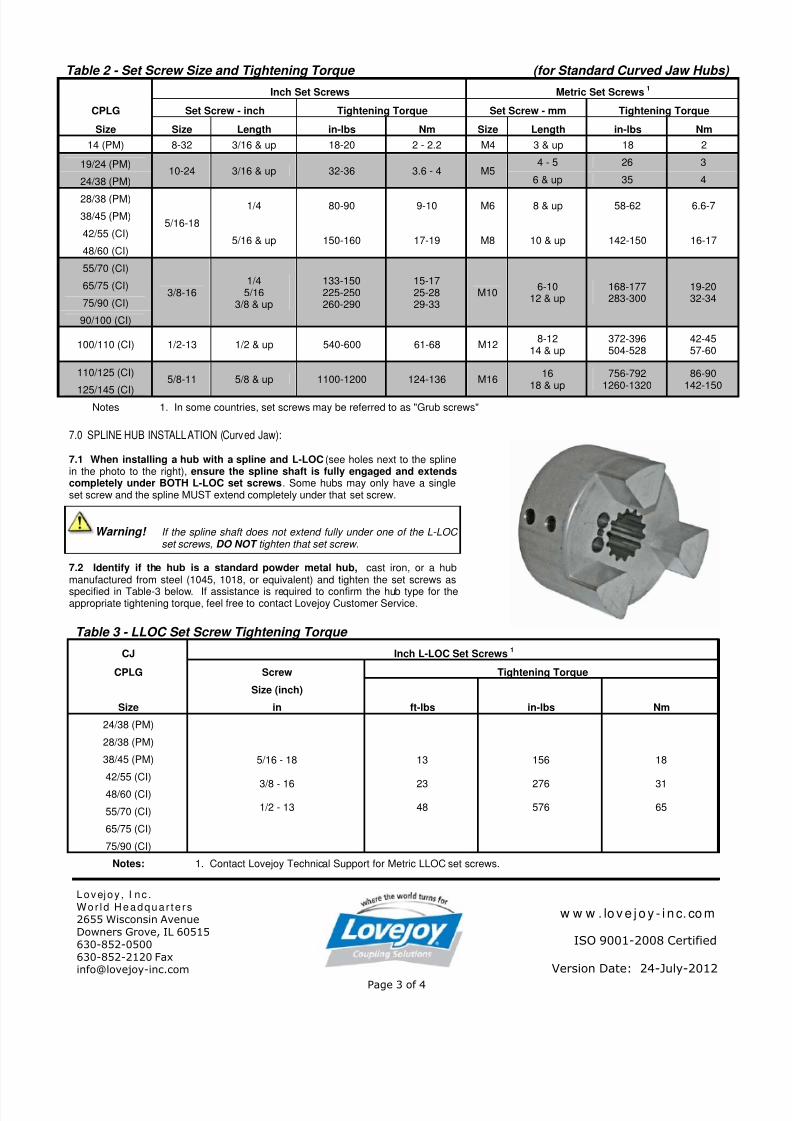
7.0 SPLINE HUB INSTALLATION (Curved Jaw):
7.1 When installing a hub with a spline and L-LOC (see holes next to the splinein the photo to the right), ensure the spline shaft is fully engaged and extendscompletely under BOTH L-LOC set screws. Some hubs may only have a singleset screw and the spline MUST extend completely under that set screw.
Warning! If the spline shaft does not extend fully under one of the L-LOC set screws, DO NOT tighten that set screw.
7.2 Identify if the hub is a standard powder metal hub, cast iron, or a hubmanufactured from steel (1045, 1018, or equivalent) and tighten the set screws as
specified in Table-3 below. If assistance is required to confirm the hub type for theappropriate tightening torque, feel free to contact Lovejoy Customer Service. Table 3 - LLOC Set Screw Tightening Torque
CJ Inch L-LOC Set Screws1
CPLG Screw Tightening Torque
Size (inch)
Size in ft-lbs in-lbs Nm
24/38 (PM)
5/16 - 18
3/8 - 16
1/2 - 13
13
23
48
156
276
576
18
31
65
28/38 (PM)
38/45 (PM)
42/55 (CI)
48/60 (CI)
55/70 (CI)
65/75 (CI)
75/90 (CI)
Notes: 1. Contact Lovejoy Technical Support for Metric LLOC set screws.
7/29/2019 CJ Install Guide July2012
http://slidepdf.com/reader/full/cj-install-guide-july2012 4/4
Page 4 of 4
Lov ejoy , I nc .
Wor ld H eadqua r te r s
2655 Wisconsin AvenueDowners Grove, IL 60515630-852-0500630-852-2120 [email protected]
w w w . lo v e j o y - i n c. co m
ISO 9001-2008 Certified
Version Date: 24-July-2012
Table 4. Curved Jaw Allowable Misalignment (Standard CJ Style)
Size Spider CL1 Misalignment
'G' Gap Maximum Displacement (offset)
Angular Axial Parallel
in mm in Degrees in in (+/-)
14 0.51 13.0 0.06 1 -0.0 / +0.040 0.00719/24 0.63 16.0 0.08 1 -0.0 / +0.047 0.00824/32 0.70 17.8 0.08 1 -0.0 / +0.055 0.00928/38 0.79 20.1 0.10 1 -0.0 / +0.060 0.01038/45 0.94 23.9 0.12 1 -0.0 / +0.070 0.01142/55 1.02 25.9 0.12 1 -0.0 / +0.079 0.01248/60 1.10 27.9 0.14 1 -0.0 / +0.082 0.01455/70 1.18 30.0 0.16 1 -0.0 / +0.087 0.01465/75 1.38 35.1 0.18 1 -0.0 / +0.102 0.016
75/90 1.57 39.9 0.20 1 -0.0 / +0.120 0.01890/100 1.77 45.0 0.22 1 -0.0 / +0.133 0.019
100 1.97 50.0 0.24 1 -0.0 / +0.150 0.020110 2.17 55.1 0.26 1 -0.0 / +0.165 0.021
125 2.36 59.9 0.28 1 -0.0 / +0.180 0.024140 2.56 65.0 0.30 1 -0.0 / +0.190 0.024160 2.95 74.9 0.35 1 -0.0 / +0.220 0.025
180 3.35 85.1 0.41 1 -0.0 / +0.250 0.027
Notes: 1. CL (Clearance) is the distance between the jaws on one hub and the face of the second hub
Table 5 - Curved Jaw Spider Dimensions
CPLG Open Center Spiders
Spider Outside Diameter Spider Width Center Opening Diameter
Size in mm in mm in mm
CJ 14 1.18 30 0.39 10 0.39 10
CJ 19/24 1.57 40 0.47 12 0.71 18
CJ24/32 2.16 55 0.55 14 1.06 27
CJ 28/38 2.56 65 0.59 15 1.15 29
CJ 38/45 3.15 80 0.71 18 1.50 38
CJ 42/55 3.74 95 0.79 20 1.81 46
CJ 48/60 4.13 105 0.83 21 2.01 51
CJ55/70 4.72 120 0.87 22 2.36 60
CJ 65/75 5.31 135 1.02 26 2.68 68
CJ 75/90 6.30 160 1.18 30 3.15 80
CJ 90/100 7.87 200 1.34 34 3.94 100
CJ 100/110 8.86 225 1.50 38 4.45 113
CJ 110/125 10.04 255 1.65 42 5.00 127
CJ 125/145 11.42 290 1.81 46 5.79 147
CJ 140 12.60 320 1.97 50 6.50 165
CJ 160 14.57 370 2.24 57 7.48 190
CJ 180 16.54 420 2.52 64 8.66 220