Embed Size (px)
Citation preview

1
CIVIL ENGINEERING COMPONENTS FOR A
CONCEPTUAL ELEVATED LIGHT RAIL TRANSIT
MODEL WITH REFERENCE TO NELSON MANDELA
BAY
JIN ZANG
brought to you by COREView metadata, citation and similar papers at core.ac.uk
provided by South East Academic Libraries System (SEALS)

2
CIVIL ENGINEERING COMPONENTS FOR A
CONCEPTUAL ELEVATED LIGHT RAIL TRANSIT
MODEL WITH REFERENCE TO NELSON MANDELA
BAY
JIN ZANG
Dissertation submitted in fulfilment of
the requirements for the degree of
Magister Technologiae: Engineering: Civil
In the Faculty of Engineering,
The Built Environment and Information Technology
at the
Nelson Mandela Metropolitan University
Promoter: Prof. JJ van Wyk
Co-promoter: Mr. Greg Pryce Lewis

3
SUMMARY
The increase of motor vehicles, especially in cities, cause transport problems of traffic
congestion, vehicle accidents, air pollution and a lack of public spaces. The
increasing number of motor vehicles consumes huge amounts of finite petrol energy
and emits large amounts of gases that are harmful to the atmosphere and the natural
environment. Therefore, the current road transport network is not a sustainable form
of public transport for the future.
In order to seek a suitable transportation mode, the Infrastructure and Engineering
Business Unit of the Nelson Mandela Bay Municipality (NMBM) did some feasibility
studies about light rail transit (LRT) from 1984 to 1988. The NMBM-report (1988: 8)
concluded that a LRT system would provide the most suitable and primary mode to
serve Nelson Mandela Bay (NMB). Although LRT was regarded as the most suitable
primary mode of transport at that time (1988), further studies that were reported in
2006 recommended an alternative public transportation system. This research
refers to these studies done for the NMB area and other studies and reports for other
areas, but focus on the identification of the most suitable civil engineering components
for a conceptual elevated light rail transit (ELRT) model.
Electrical driven LRT systems have advantages over internal-combustion driven
vehicles in terms of environmental protection. Traditional LRT systems are at ground
level and are integrated with the existing road network. Some successful LRT
systems indicate that the success of LRT systems is mainly dependent on integration
with the existing road network. However, the integration of road transport systems
with LRT systems cause increased congestion and accidents. An ELRT system can
solve these problems. Bangkok has already built an ELRT system to solve its severe
traffic congestion.

4
In order to develop a conceptual ELRT model, this research aimed to determine the
most suitable civil engineering components for a conceptual ELRT model, including:
(i) the most suitable type of bridge foundation;
(ii) the most suitable type bridge girder;
(iii) the most suitable type of sleeper; and
(iv) whether the track should be a ballasted or non-ballasted type.
The grounded theory approach was adopted to build up sets of data from which the
most suitable components could be selected. In addition, design analyses were
done of the various types of components to determine their suitability for a conceptual
ELRT model. Experienced engineers and experts were also consulted to identify the
most suitable components. After analyses and selection of the most suitable
components, outstanding experts were approached to evaluate the components that
showed up as the most suitable through the research.
The research results indicated that bored and cast-in-place piles, a double-cell
trapezoidal segmental box girder, and twin-block sleepers on a non-ballasted sleeper
bed are the most suitable civil engineering components.
5
CONTENTS
CHAPTER 1
INTRODUCTION ............................................................................................................................1
1.1 CONTEXT OF THE RESEARCH PROBLEM ....................................................................................1
1.2 THE STATEMENT OF THE PROBLEM...........................................................................................2
1.3 THE STATEMENT OF THE SUB-PROBLEMS: ................................................................................2
1.4 HYPOTHESES..........................................................................................................................2
1.5 DELIMITATIONS OF THE RESEARCH ...........................................................................................3
1.6 RESEARCH OBJECTIVES ..........................................................................................................4
1.7 RESEARCH METHODOLOGY......................................................................................................4
1.7.1 Secondary sources ......................................................................................................5
1.7.2 Primary sources ...........................................................................................................5
1.7.3 Data analysis ................................................................................................................6
1.8 OVERVIEW OF THIS STUDY .......................................................................................................6
CHAPTER 2
LITERATURE REVIEW ON LIGHT RAIL TRANSIT SYSTEMS ....................................................9
2.1 INTRODUCTION........................................................................................................................9
2.2 BACKGROUND ......................................................................................................................10
2.2.1 Main factors that lead to transportation problems ..................................................10
2.2.2 Sustainable transportation ........................................................................................10
2.2.3 Main transportation problems ................................................................................... 11
2.3 SOME PREVIOUS STUDIES OF LRT SYSTEMS ...........................................................................13
2.3.1 Light Rail in Africa (with reference to the NMBM) ...................................................13
2.3.2 Experience of LRT systems in U.S.A. .......................................................................14
2.3.2.1 Reasons to choose LRT.........................................................................................15
2.3.2.2 The importance of planning....................................................................................16
6
2.3.2.3 The features of Portland’s LRT system ..................................................................18
2.3.2.4 The advantages and disadvantages of LRT systems.............................................18
2.3.3 Experience of LRT in Canada ....................................................................................21
2.3.3.1 Why LRT was chosen in Calgary ...........................................................................21
2.3.3.2 The importance of planning....................................................................................22
2.3.3.3 The lessons of the Calgary LRT system ................................................................22
2.4 THE BUDGETS OF SOME LRT PROJECTS.................................................................................24
2.5 ENVIRONMENTAL FACTORS ....................................................................................................26
2.6 BANGKOK ELRT SYSTEM......................................................................................................27
2.7 SUMMARY AND CONCLUSIONS................................................................................................27
CHAPTER 3
LITERATURE REVIEW ON THE MAIN CIVIL ENGINEERING COMPONENTS FOR A
CONCEPTUAL ELRT MODEL ....................................................................................................30
3.1 INTRODUCTION......................................................................................................................30
3.2 MAIN CIVIL ENGINEERING COMPONENTS FOR THE CONCEPTUAL ELRT MODEL..........................30
3.2.1 ELRT foundations.......................................................................................................31
3.2.1.1 Characteristics of different types of foundations ....................................................32
3.2.1.1.1 Pad foundations ..............................................................................................32
3.2.1.1.2 Strip foundations..............................................................................................32
3.2.1.1.3 Raft foundations ..............................................................................................33
3.2.1.1.4 Piled foundations .............................................................................................33
3.2.1.2 Bridge foundations .................................................................................................33
3.2.1.2.1 Effect of settlement on bridges ........................................................................34
3.2.1.2.2 Types of pile foundations .................................................................................35
3.2.1.2.3 Choice of piled foundations .............................................................................36
3.2.1.2.4 Advantages and disadvantages of types of pile foundations ...........................36
3.2.1.2.5 Specific application for each type of piles........................................................40
3.2.1.3 Analysis of bored and cast-in-place piles in different types of soils........................42
3.2.1.3.1 General soil types............................................................................................42
7
3.2.1.3.2 Soil types by grain size....................................................................................43
3.2.1.3.3 Bored and cast-in-place piles in coarse-grained soils .....................................44
3.2.1.3.4 Bored and cast-in-place piles in fine-grained soils ..........................................45
3.2.1.4 Effects of horizontal or inclined loads on foundation piles ......................................46
3.2.1.4.1 Effects of horizontal or inclined loads on short piles ........................................46
3.2.1.4.2 Effects of horizontal or inclined loads on long piles .........................................47
3.2.2 ELRT girders ...............................................................................................................48
3.2.2.1 The effects of different types of cross-section under loads ....................................51
3.2.2.1.1 Analysis of the moment of inertia for three forms of cross-section ..................54
3.2.2.1.2 Analysis of the influence of torsion moment among three forms of
cross-sectional girders ...................................................................................................59
3.2.2.2 Analysis of box girders ...........................................................................................65
3.2.2.2.1 Some forms of box girders used in America ....................................................66
3.2.2.2.2 A technique used for the construction of box girders .......................................69
3.2.2.2.3 Functional and economical aspects of the construction of box girders............69
3.2.2.2.4 Some of the problems about box girders to consider during the design
procedure .......................................................................................................................74
3.2.2.2.5 Design Challenges for Rail Bridges .................................................................76
3.2.2.2.6 Two case studies about pre-cast concrete segmental box girder railway
structures .......................................................................................................................79
3.2.3 ELRT sleepers and sleeper beds ..............................................................................82
3.2.3.1 Choosing among different sleepers .......................................................................84
3.2.3.2 Choosing whether the track should be a non-ballasted or ballasted type ..............84
3.2.3.2.1 Non-ballasted railway track versus ballasted railway track..............................85
3.2.3.2.2 Basic criteria for choosing non-ballasted or ballasted railway track.................87
3.2.3.3 Introduction of non-ballasted tracks for urban rail systems ....................................89
3.2.3.3.1 Main types of non-ballasted railway track........................................................89
3.2.3.3.2 Recent developments in slab track..................................................................95
3.2.3.3.3 Analysis of the popular non-ballasted railway tracks .....................................100
3.2.3.3.4 Twin-block sleepers .......................................................................................101
8
3.2.3.3.5 Installation of twin block sleepers ..................................................................102
3.2.3.4 Noise and vibration problems of non-ballasted railway tracks for urban rail systems
.........................................................................................................................................103
3.2.3.5 Proposed railway track systems for the conceptual ELRT model ........................105
3.3 SUMMARY AND CONCLUSIONS..............................................................................................107
CHAPTER 4
RESEARCH METHODOLOGY..................................................................................................108
4.1 INTRODUCTION....................................................................................................................108
4.2 RESEARCH METHODOLOGY..................................................................................................108
4.2.1 Qualitative versus quantitative research methodology ........................................108
4.2.2 The specific qualitative approach for this research: grounded theory approach
............................................................................................................................................109
4.2.3 Data collection methods .......................................................................................... 110
4.2.3.1 Dataset 1: Previous studies about LRT in NMB ................................................... 110
4.2.3.2 Dataset 2: Previous case studies on LRT systems .............................................. 110
4.2.3.3 Dataset 3: Guidelines from literature for the most suitable civil engineering
components for a conceptual ELRT model ...................................................................... 111
4.2.3.4 Dataset 4: Questionnaire surveys among engineers, experts and scholars......... 111
4.2.3.5 Dataset 5: Review of the conceptual ELRT model by civil engineering experts ... 112
4.2.4 Data analysis ............................................................................................................ 112
4.2.4.1 Dataset 1: Previous feasibility study in NMB........................................................ 113
4.2.4.2 Dataset 2: Analysis of case studies...................................................................... 113
4.2.4.3 Dataset 3: Analyses of suitable civil engineering components for the conceptual
ELRT model ..................................................................................................................... 113
4.2.4.4 Dataset 4: Analysis of feedback on questionnaires.............................................. 114
4.2.4.5 Dataset 5: Analysis of the experts’ review of the civil engineering components
selected for the conceptual ELRT model ......................................................................... 115
4.2.5 Validity and reliability of data .................................................................................. 115
4.3 SUMMARY AND CONCLUSIONS.............................................................................................. 116
9
CHAPTER 5
RESULTS OF THE EMPIRICAL INVESTIGATION....................................................................118
5.1 INTRODUCTION.................................................................................................................... 118
5.2 MOST SUITABLE CIVIL ENGINEERING COMPONENTS FOR THE CONCEPTUAL ELRT MODEL........ 118
5.2.1 Suitable ELRT foundation for the conceptual ELRT model .................................. 119
5.2.1.1 Criteria for ELRT foundations for the conceptual ELRT model............................. 119
5.2.1.2 Most suitable foundation for the conceptual ELRT model ....................................124
5.2.2 Suitable ELRT girder for the conceptual ELRT model ..........................................128
5.2.2.1 Criteria for ELRT girders for the conceptual ELRT model ....................................128
5.2.2.2 Most suitable girder for the conceptual ELRT model............................................133
5.2.2.3 Suitable bridge types for the conceptual ELRT model .........................................135
5.2.3 Suitable ELRT sleepers for the conceptual ELRT model ......................................138
5.2.3.1 Criteria of ELRT sleepers for the conceptual ELRT model...................................138
5.2.3.2 Most suitable types of sleepers and sleeper beds for the conceptual ELRT model
.........................................................................................................................................143
5.2.4 Suitability of ballasted or non-ballasted sleeper bed for the conceptual model 146
5.2.4.1 Most suitable type of sleeper bed ........................................................................146
5.3 SUMMARY AND CONCLUSIONS..............................................................................................147
CHAPTER 6
EXPERTS’ REVIEW ON THE MOST SUITABLE CIVIL ENGINEERING COMPONENTS FOR
THE CONCEPTUAL ELRT MODEL ..........................................................................................149
6.1 INTRODUCTION....................................................................................................................149
6.2 MOST SUITABLE CIVIL ENGINEERING COMPONENTS FOR THE CONCEPTUAL ELRT MODEL........149
6.2.1 Bored and cast-in-place piles..................................................................................150
6.2.2 A double-cell trapezoidal segmental box girder ....................................................151
6.2.3 Twin-block sleepers on a non-ballasted sleeper bed ............................................151
6.3 SUMMARY AND CONCLUSIONS..............................................................................................153
CHAPTER 7

10
CONCLUSIONS AND RECOMMENDATIONS FOR FUTURE RESEARCH .............................154
7.1 INTRODUCTION....................................................................................................................154
7.2 CONCLUSIONS ....................................................................................................................154
7.3 RECOMMENDATIONS FOR FUTURE RESEARCH .......................................................................155
REFERENCE LIST.....................................................................................................................156
APPENDIX A
QUESTIONNAIRE ON THE MOST SUITABLE BRIDGE FOUNDATION FOR THE
CONCEPTUAL ELRT MODEL ..................................................................................................163
APPENDIX B
QUESTIONNAIRE ON THE MOST SUITABLE BRIDGE GIRDER FOR THE CONCEPTUAL
ELRT MODEL ............................................................................................................................168
APPENDIX C
QUESTIONNAIRE ON THE MOST SUITABLE RAILWAY SLEEPER FOR THE CONCEPTUAL
ELRT MODEL ............................................................................................................................174
APPENDIX D
STATISTICAL RESULTS OF QUESTIONNAIRE SURVEYS.....................................................178
APPENDIX E
SUMMARY OF RESPONSES FROM QUESTIONNAIRE SURVEYS........................................190
APPENDIX F
EXPERT REVIEW OF SUITABLE CIVIL ENGINEERING COMPONENTS FOR A CONCEPTUAL
ELRT MODEL ............................................................................................................................194
APPENDIX G
SUMMARY OF RESPONSES FROM EXPERT REVIEW ..........................................................199

11
LIST OF TABLES
TABLE 2.1: CALGARY LRT AND BUS COLLISIONS AND PASSENGER ACCIDENTS...................................22
TABLE 2.2: LIGHT RAIL PROJECTS COMPLETED WITHIN BUDGET .......................................................25
TABLE 2.3: RELATIVE CONTRIBUTION OF GASES TO GLOBAL WARMING, 1989 ......................................26
TABLE 2.4: CARBON DIOXIDE (CO2) EMISSIONS PER TYPE OF FUEL....................................................27
TABLE 3.1: SECTIONAL SHAPES FOR BRIDGE SUPERSTRUCTURES ......................................................51
TABLE 3.2: BRIDGE TYPES AND DEFICIENCIES FROM AUGUST 2000 FHWANBI DATA...........................71
TABLE 3.3: FATAL FLAWS AND ECONOMICAL EVALUATION....................................................................73
TABLE 3.4: ATTRIBUTES OF DIFFERENT TYPES OF NON-BALLASTED RAILWAY TRACK ...........................92
TABLE 5.1: THE IMPORTANCE OF CRITERIA FROM CIVIL ENGINEERS, EXPERTS AND SCHOLARS............120
TABLE 5.2: THE IMPORTANCE OF FOUNDATION CRITERIA FROM STATISTICAL RESULTS ........................124
TABLE 5.3: THE SUITABILITY OF TYPE(S) OF BRIDGE FOUNDATION(S) ................................................125
TABLE 5.4: THE IMPORTANCE OF CRITERIA FROM CIVIL ENGINEERS, EXPERTS AND SCHOLARS............129
TABLE 5.5: THE IMPORTANCE OF GIRDER CRITERIA FROM STATISTICAL RESULTS................................132
TABLE 5.6: THE SUITABILITY OF TYPE(S) OF BRIDGE GIRDER(S) ........................................................133
TABLE 5.7: THE SUITABILITY OF BRIDGE TYPE(S) .............................................................................136
TABLE 5.8: THE IMPORTANCE OF CRITERIA FROM CIVIL ENGINEERS, EXPERTS AND SCHOLARS............139
TABLE 5.9: THE IMPORTANCE OF RAILWAY SLEEPER CRITERIA FROM STATISTICAL RESULTS ................142
TABLE 5.10: THE SUITABILITY OF TYPE(S) OF RAILWAY SLEEPER(S)...................................................144

12
LIST OF FIGURES
FIGURE 1.1: LAYOUT OF DISSERTATION..............................................................................................8
FIGURE 3.1: COMPARISON OF SINGLE PILE AND PILE GROUP UNDER HORIZONTAL LOADS .....................48
FIGURE 3.2: SKETCH FOR ANALYSIS OF A SIMPLY-SUPPORTED GIRDER UNDER LOADS..........................52
FIGURE 3.3: COMPARISON OF THREE DIFFERENT CROSS-SECTIONAL FORMS ......................................54
FIGURE 3.4: ANALYSIS OF THE MOMENT OF INERTIA OF T CROSS-SECTIONAL FORM.............................55
FIGURE 3.5: ANALYSIS OF THE MOMENT OF INERTIA OF I CROSS-SECTIONAL FORM ..............................57
FIGURE 3.6: ANALYSIS OF THE MOMENT OF INERTIA OF BOX CROSS-SECTIONAL FORM.........................58
FIGURE 3.7: MEANING OF SYMBOLS IN BOX CROSS-SECTIONAL FORM..............................................62
FIGURE 3.8: MEANING OF SYMBOLS IN T CROSS-SECTIONAL FORM..................................................63
FIGURE 3.9: MEANING OF SYMBOLS IN I CROSS-SECTIONAL FORM...................................................64
FIGURE 3.10: BOX GIRDER BRIDGE ..................................................................................................66
FIGURE 3.11: MARTA CS360 AND CN480-FIRST PRE-CAST SEGMENTAL CONCRETE BRIDGES BUILT FOR
RAIL USE IN THE UNITED STATES ......................................................................................................80
FIGURE 3.12: MARTA CS360 AND CN480-FIRST USE OF TWIN TRIANGULAR TRUSSES FOR
SPAN-BY-SPAN CONSTRUCTION. .......................................................................................................81
FIGURE 3.13: CONSTRUCTION CONTINUED THROUGH CONGESTED ATLANTA, MINIMIZING DISRUPTION TO
EXISTING TRAFFIC. ..........................................................................................................................81
FIGURE 3.14: JFK LIGHT RAIL SYSTEM-COMPLETED ELEVATED TRACK INCORPORATED DETAILS TO
CREATE AN AESTHETICALLY PLEASING STRUCTURE............................................................................82
FIGURE 3.15: THE SHINKANSEN SLAB TRACK....................................................................................96
FIGURE 3.16: PROFILE CHART OF RHEDA 2000 SYSTEM....................................................................97
FIGURE 3.17: BOGL SYSTEM ...........................................................................................................98
FIGURE 3.18: EDILON BLOCK TRACK ................................................................................................99
FIGURE 3.19: TWIN-BLOCK SLEEPERS............................................................................................103
FIGURE 3.20: STEDEF TWIN-BLOCK SYSTEMS ................................................................................104
13
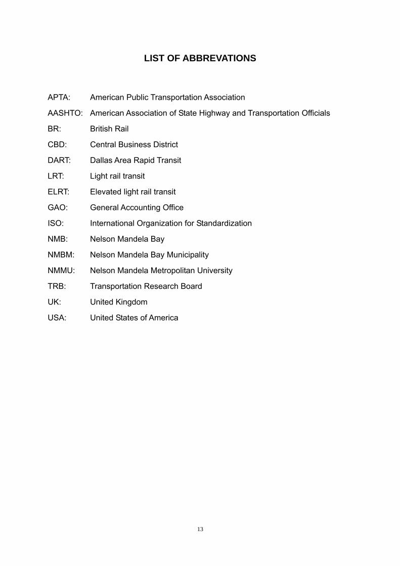
LIST OF ABBREVATIONS
APTA: American Public Transportation Association
AASHTO: American Association of State Highway and Transportation Officials
BR: British Rail
CBD: Central Business District
DART: Dallas Area Rapid Transit
LRT: Light rail transit
ELRT: Elevated light rail transit
GAO: General Accounting Office
ISO: International Organization for Standardization
NMB: Nelson Mandela Bay
NMBM: Nelson Mandela Bay Municipality
NMMU: Nelson Mandela Metropolitan University
TRB: Transportation Research Board
UK: United Kingdom
USA: United States of America

14
ACKNOWLEDGEMENTS
This research could not be completed without the support of many individuals and
organizations. I appreciate the support of the following people and organizations
and sincerely thank them for their time, guidance, and their expertise.
My promoter Prof. JJ van Wyk, for his time, guidance, patience, support and
encouragement.
My co-promoter Mr. Greg Pryce Lewis, for his support and time.
Mr. J van der Mescht, for his guidance, support and time.
My mother, for her encouragement to persevere with my research.
Mrs. Hogan, for her support and information.
The American Association of State Highway and Transportation Officials and the
staff who supported me with my questionnaire surveys and expert reviews.
The USA Transportation Research Board for their support regarding my
dissertation and questionnaire surveys.
Some Chinese engineers, for their support with my questionnaire surveys and
expert reviews.
The Australian PhD Scholar, for his expertise and support with my questionnaire
surveys.
Dr. Shaun Krause, for his support.
Dr. Jacques Pietersen, for his support with the statistics.
Nelson Mandela Metropolitan University, for support and financial assistance.
All the others who helped me with my research.

1
CHAPTER 1
INTRODUCTION
Light rail transit (LRT) systems are powered by electricity. LRT lines are less
expensive to construct than a traditional subway line and they have a greater
transportation capacity. As a result, LRT has been well received in North America
and Europe. According to Ginn (1998: 11), LRT provide easy access for the people
to travel with limited environmental and social disturbance. Although LRT has been
developed over many years, the formal definition of LRT was only adopted in 1989.
The Transportation Research Board’s Urban Public Transportation Glossary defines it
as:
“A metropolitan electric railway system characterized by its ability to operate
single cars or short trains along exclusive rights-of-way at ground level, on aerial
structures, in subways, or occasionally, in streets and to board and discharge
passengers at track or car floor level” (American Public Transportation Association
(APTA), 2002: 3).
The aim of this study is to identify the most suitable civil engineering components for a
conceptual elevated light rail transit (ELRT) model. This chapter introduces the
research and provides the research problems, the hypotheses, the research
methodology and other related information.
1.1 Context of the research problem
The transportation problems encountered by most cities in the world include traffic
congestion, traffic accidents, air pollution and a lack of public spaces. Nelson
Mandela Bay (NMB) is also faced with such problems. LRT systems that are located
2
at ground level in some cities, offer solutions to these public transportation problems.
In order to offer a solution to the demands that future public transport may bring, the
civil engineering components will be identified for a conceptual ELRT model in this
research. ELRT may offer a solution to the problem of limited land space that ground
operating transport systems encounter because it operates at an elevated level.
1.2 The statement of the problem
The main problem is to determine which civil engineering components will be most
suitable for a conceptual ELRT model. Reference will be made to the NMB area in
view of previous studies and consideration of a LRT system by the Nelson Mandela
Bay Municipality (NMBM).
1.3 The statement of the sub-problems:
The first sub-problem is to determine what type of bridge foundation is most
suitable for a conceptual ELRT model.
The second sub-problem is to determine what type of bridge girder is most
suitable for a conceptual ELRT model.
The third sub-problem is to determine what type of railway sleeper is most
suitable for a conceptual ELRT model.
The fourth sub-problem is to determine whether the track should be a
ballasted or non-ballasted type for a conceptual ELRT model.
1.4 Hypotheses
The first hypothesis is that the bored and cast-in-place piles are most suitable
for a conceptual ELRT model.
The second hypothesis is that trapezoidal segmental box girders are most
suitable for a conceptual model.

3
The third hypothesis is that twin-block sleepers are most suitable for a
conceptual ELRT model.
The fourth hypothesis is that the track should be a non-ballasted type for a
conceptual ELRT model.
1.5 Delimitations of the research
The main purpose of the research is to determine which civil engineering components
are most suitable for a conceptual ELRT model. In order to achieve this purpose, the
research will focus on following aspects:
Analysing types of bridge foundations to determine what type of foundations
are most suitable for a conceptual ELRT model.
Analysing types of bridge girders to determine what type of girders are most
suitable for a conceptual ELRT model.
Analysing types of railway sleepers to determine what type of railway sleepers
are most suitable for a conceptual ELRT model.
Analysing whether the track should be a ballasted or non-ballasted type for a
conceptual ELRT model.
This research will only focus on the technologies aspect of the above four civil
engineering components concerning a conceptual ELRT model. This research will
determine the types of bridge foundations, bridge girders, railway sleepers and
whether the track should be a ballasted or non-ballasted type. The design codes
and design conditions are not the same in different countries and for different practical
ELRT projects. For this reason, the exact dimensions and carry capacities for these
main civil engineering components of a conceptual ELRT model will have to be
determined during the practical design of each ELRT system in its specific
circumstances and will not be discussed in this dissertation.
4
The aim of this research is to determine the main civil engineering components of a
conceptual ELRT model. The other civil engineering components that a conceptual
ELRT model is composed of, such as pillars, ELRT stations and rails will not be
discussed. The conceptual ELRT model uses electricity as a source of power, but
this research will not discuss the electricity technology and its role in ELRT.
1.6 Research objectives
The intention of this research is to identify the most suitable civil engineering
components for a conceptual ELRT model. The objectives of this research are as
follows:
To analyse bridge foundations and to identify the most suitable type of
foundation for a conceptual ELRT model;
To analyse bridge girders and to identify the most suitable type of bridge girder
for a conceptual ELRT model;
To analyse railway sleepers and to identify the most suitable type of railway
sleeper for a conceptual ELRT model;
To analyse the track/ sleeper bed and to determine whether it should be a
ballasted or non-ballasted type for a conceptual ELRT model.
1.7 Research methodology
The main purpose of this research is to determine which civil engineering components
are most suitable for a conceptual ELRT model. Leedy (2005: 140) states that the
grounded theory approach was mainly aimed at data analysis and to use the data to
develop a theory or a model. In order to construct a theoretical model, grounded
theory uses a set of procedure to analyze data. Further, Tan (2004: 48) states that in
order to build a hypothesis from specific instances, grounded theory is used as an
inductive approach.
5
According to Fellows & Liu (2003: 103), grounded theory also uses case studies to
develop a theory. Chapter 2 reviews case studies of some successful LRT projects
that will help to develop the conceptual ELRT model. Due to the exploratory nature
of this research, the emphasis will be on exploring civil engineering components that
would be most suitable for a conceptual ELRT model, rather than confirming any
previously proven views. For the above reasons, the grounded theory is the most
suitable methodology for this research. Through the grounded theory approach, the
main civil engineering components that is most suitable for a conceptual ELRT model
has been developed.
The data will be obtained from both secondary and primary sources.
1.7.1 Secondary sources
The secondary data will be acquired through books, journals, conference papers,
databases and previous studies on the subject.
1.7.2 Primary sources
The primary data will be gathered by means of questionnaire surveys on the main civil
engineering components for a conceptual ELRT model, together with expert reviews
on the main civil engineering components that are most suitable for a conceptual
ELRT model.
Before the questionnaire surveys and expert reviews will be conducted, various types
of the main civil engineering components will be listed for the respondents to choose.
Scales showing different types of civil engineering components will enable the
respondents to consider which components would be best suited for a conceptual
ELRT model. The respondent must include railway engineers, bridge engineers and

6
engineering scholars. South Africa does not have an ELRT system as yet, therefore
many of the ELRT experts are not in South Africa. This makes it impossible to do
face to face interviews with experts. A range of questions based on the main
problem and sub-problems of this research, together with the relevant literature will be
formulated in a questionnaire. The questionnaire will be sent by means of
electronic-mail (e-mail) to the engineers, experts and scholars in the relevant fields.
With the help of the Nelson Mandela Metropolitan University (NMMU) librarian,
electronic journals, conference papers and previous theses will be collected.
Information on the latest technology of high-speed railways and bridge technology will
also contribute to determining the main civil engineering components that would be
most suitable for a conceptual ELRT model.
1.7.3 Data analysis
After obtaining the primary and secondary data, the data will be analyzed by means of
categorisation, interpretation and comparison according to the main problem and
sub-problems. The data will then be analysed and synthesized to identify the most
suitable civil engineering components for a conceptual ELRT model.
The data will then be validated and verified by means of an expert review from railway
and bridge engineers, and civil engineering experts.
1.8 Overview of this study
The layout of the dissertation is illustrated in figure 1.1 below. Chapter 1 presents an
introduction to the research, the background knowledge, the research problems, the
delimitations and the objectives of this research. Chapter 2 presents a literature
review of LRT. Chapter 3 reviews the main civil engineering components for a
conceptual ELRT model. Chapter 3 is divided into three sections: Section 1 covers
7
the ELRT foundation; Section 2 the ELRT girder and Section 3 the ELRT sleepers.
Chapter 4 presents the methodology of this research. Chapter 5 presents the
empirical results obtained from the questionnaire surveys. Chapter 6 will reports on
the expert review. Chapter 7 concludes this dissertation and indicates possible
future research opportunities.

8
Figure 1.1: Layout of Dissertation
Chapter 1 Introduction
Chapter 2 Literature review of LRT systems
Chapter 3 Literature review on the main civil
engineering components for a conceptual ELRT model
Section 3 ELRT sleepers and sleeper beds
Section 2 ELRT girder
Section 1 ELRT foundation
Chapter 5 Results of the empirical
investigation
Chapter7 Conclusions and recommendations
for future research
Chapter 4 Research methodology
Chapter 6 Expert’s review on the most suitable civil engineering components for the
conceptual ELRT model

9
CHAPTER 2
LITERATURE REVIEW ON LIGHT RAIL TRANSIT SYSTEMS
2.1 Introduction
Public transportation provides people with a convenient means for travelling to and
from work, or for recreational purposes. The growth of the economy and new
technological developments resulted in a transportation environment that has
changed a great deal. More efficient environmental protection systems are needed.
Traditional transportation systems cannot keep up with the demand for modern
development. Hence, new transportation systems are needed to adapt to the new
requirements. This research aims to determine the main civil engineering
components that are most suitable for a conceptual ELRT model. Before analyzing
the main civil engineering components, some information about previous LRT and
ELRT studies will be introduced.
This chapter is divided into six parts. The first part introduces the background
information. This part discusses the main factors that lead to the main transportation
problems that most metropolitan cities are facing, and which lead to unsustainable
development. The second part introduces previous LRT studies, including LRT
studies of the NMB area and some successful LRT systems abroad. The third part
investigates the budgets needed for some typical LRT projects. The fourth part
investigates the environmental factors that need to be considered in an LRT project.
The fifth part introduces the Bangkok ELRT system that will help to determine the
main civil engineering components for a conceptual model. The sixth part
summarizes the contents of this chapter.

10
2.2 Background
More and more vehicles are on the roads and people have begun to complain about
transport problems such as traffic congestion and air pollution, which brings about
adverse effects on city development. Among various factors that cause
transportation problems, some are prominent and provide an insight into the current
transportation problems. These aspects need to be seriously considered when
undertaking city planning and development.
2.2.1 Main factors that lead to transportation problems
Technology and transportation systems have developed rapidly around the world.
Most transportation problems have occurred with the rapid increase in motor vehicle
ownership. According to Rodrigue (2005: 1), transport system use complex spatial
structures to accumulate and concentrate economic activities. Therefore, most
transport problems occur in urban areas. The World Bank Group (2002: 2) also
emphasizes that the adverse impacts of modern urban transport systems became
more apparent to the public officials and general public.
2.2.2 Sustainable transportation
Sustainable development has become a well-known concept. However, the use of
resources such as soils, minerals, and finite fossil fuels all form part of the daily
activities of people. These resources cannot be sustained forever. Most countries
use motor vehicles as the main mode of transportation and this does not assist with
sustainable transportation. According to Banister (2005: 7), the increase in the car
ownership resulted in urban sprawl, consumption of land for transport, and fossil fuel
consumption. This was also proved by Black (2006: 4) who stated that the highway
motor vehicle transportation systems are non-sustainable for the reasons as follows:
11
They uses a finite fossil fuel, which creates local air-quality problems and
contributes to global warming;
they produce an excessive number of fatalities and injuries; and
they suffer from congestion in major urban areas.
According to Kastenholz (1991: 2), a single type of transport system cannot be
suitable for all transportation needs and circumstances. Therefore, diverse
transportation systems must complement one another to make transportation systems
more efficient. A conceptual ELRT model, to which this study will contribute, will
provide an efficient transportation mode for public transport. The emphasis of this
research is to determine the most suitable civil engineering components for a
conceptual ELRT model.
2.2.3 Main transportation problems
According to Rodrigue (2005: 1), the productivity of urban areas is highly dependent
on the efficiency of its transport systems to move labour, consumers and freight
between multiple origins and destinations. Some problems like traffic congestion
have already existed for a long time. Other problems like urban freight distribution
and environmental impacts are more recent. The diffusion of internal combustion
engines emitting carbon dioxide (CO2) leads to global warming. The most notable
urban transport problems are:
Traffic congestion and parking difficulties. Rodrigue (2005: 1) argues that
congestion is one of the most prevalent transport problems in large urban
areas, particularly with the increase of vehicles on the roads. It occurs when
increasing demand for transport infrastructure cannot keep up with the
increase in the number of vehicles.
Public transport inadequacy. Rodrigue (2005: 1) explains that many
public transit systems, or parts of them, are either over- or under-utilised.
12
They are too crowded during peak hours and create discomfort for
passengers. Furthermore, low ridership (passenger numbers) makes
services financially unsustainable, especially in lower density areas.
Difficulties for pedestrians. Rodrigue (2005: 1) indicates that difficulties for
pedestrians are mainly the outcome of intense traffic, where the mobility of
pedestrians and vehicles are impaired. The lack of consideration for
pedestrians in the physical design of facilities is another factor.
Loss of public space. Rodrigue (2005: 1) maintains that most roads are
freely accessible and publicly owned. The increase in automobiles has
resulted in land for transportation systems gradually taking up the available
public spaces. The life and interactions of residents and their use of street
space are influenced by traffic flows.
Environmental impacts and energy consumption. Rodrigue (2005: 1)
shows that the pollution and noise generated by motor vehicles reduce the
quality of life of urban populations. Furthermore, the dependency on
petroleum by urban transportation has dramatically increased.
Accidents and safety. Rodrigue (2005: 1) emphases that a growing
number of accidents and fatalities are caused by the increasing traffic in urban
areas, especially in developing countries. People feel less safe to use the
streets as traffic increases.
Land consumption. Rodrigue (2005: 2) claims that the over-reliance on
some forms of urban transportation leads to between 30 to 60 percent of
metropolitan areas being occupied by transportation systems. In addition,
the increase in road vehicles, such as privately owned cars, makes the
existing road network more congested.
Freight distribution. Rodrigue (2005: 2) states that growing quantities of
freight, moving within metropolitan areas, were produced by the
materialization of the economy. The mobility of freight in urban areas has
become increasingly problematic, because freight traffic commonly shares
infrastructures with passengers traffic.

13
From the above, it can be deduced that certain forms of transportation systems do not
make use of land efficiently. In order to relieve environmental and energy
consumption problems, vehicles that are driven by electricity would provide a better
solution. In order to use land more efficiently, elevated structures can be considered,
because additional space is created at ground level. Most accidents occur at
intersections or are caused by careless drivers. Elevated structures and a specific
track can help prevent the accidents caused by careless drivers. Therefore, diverse
transportation systems could provide a better solution for sustainable development in
urban areas.
2.3 Some previous studies of LRT systems
In this part, two case studies: 1) Portland LRT and 2) Sacramento LRT will be
introduced. These examples include the purposes for which they were developed
and the successes that were recorded. Light rail has also been developed in Africa
since 1985, but was only implemented in Tunisia and Egypt. The experiences of
these LRT systems have great value for the development for a conceptual ELRT
model. The studies on these typical LRT systems are discussed henceforth:
2.3.1 Light Rail in Africa (with reference to the NMBM)
According to Taplin (1998: 1) light rail in Africa is limited to Tunisia and Egypt.
Tunisia developed a 32-kilometre system in 1985, using German-built articulated cars
and operating four surface lines that carry 90 million passengers per year. In
Alexandria, Egypt, is a street tramway and suburban light rail line, while in the Cairo
area, modernized light rail lines exist in Heliopolis and Helwan. Taplin states that
light rail has existed for 21 years in Africa. Although there are no LRT systems in
Africa besides those in Tunisia and Egypt, some studies have already been
conducted by the NMBM in the past.

14
Feasibility studies concerning the possibility of the constructing of an LRT system in
the NMB area were carried out and revised by the NMBM between 1984 and 1989.
The NMBM-report (1988: 8) concluded that a LRT system was suitable for use in the
NMB area at that time.
The LRT system was said to be a suitable transport mode for the NMB in 1988.
However, the more recent NMBM-report (2006: 5) concluded that a trunk bus route
corridor together with the local bus and minibus-taxi services based system would
best serve the NMB area for the next 10 years. It explained that this would provide
better travel standards and less operating costs for the people of the NMB
(NMBM-report, 2006: 32). The NMBM-report (2006: 5) also concluded that there
would not be enough passengers for an expanded railway system in the next 10 years.
Only Motherwell in the north of the NMB would benefit from a new railway
development, but this would only be viable if densification reached higher levels along
the corridor that connects Motherwell to the central business district (CBD).
Therefore, it would only be reconsidered again in approximately 10 years time, when
more details can be acquired in order to justify the investment of a LRT railway service
(NMBM-report, 2006: 32).
Although the NMBM decided to use a trunk bus based system in the NMB area, this
research will contribute to the future decisions of the NMBM regarding the introduction
of an ELRT system. In addition, seeing that it is aimed at determining the most
suitable civil engineering components for a conceptual ELRT model, the research
results can inform any metropolitan city in the world in their consideration of an ELRT
system.
2.3.2 Experience of LRT systems in U.S.A.
Many factors need to be considered in city planning and development, among others,

15
transportation systems. LRT systems were introduced in America as a measure to
relieve the increasing transportation problems and these LRT systems have been
successful in some cities. This section highlights certain aspects of LRT systems
with reference to experiences in the USA.
2.3.2.1 Reasons to choose LRT
Roads or highways have become the main transportation system around the world.
According to Hoyt (1988: 101), the cost of a LRT system in Sacramento was about 9.6
million dollars per mile, while the interstate highway project would have cost 25 million
dollars a mile. The LRT systems need fewer operators than buses to operate with
the same efficiency. Hoyt (1988: 101) confirms that, with the same number of drivers,
the new light rail has the capacity to carry 10 times as many people as they did with
their previous transit system. In order to save funds, the rail operators have been
transferred from buses to LRT, but still earn the same hourly rate. Therefore, they
are carrying 700 people on four-car trains instead of carrying only 70 people on the
bus.
Sometimes it is not clear whether the LRT system could create enough benefits
compared to other transportation systems. Although the economic development
benefit of a LRT system is not as apparent as with other transportation systems, the
purpose of LRT service is to move people throughout a region efficiently (The Urban
Land Institute, 2001: 32). The benefits of LRT will only be realized as this form of
transport is accepted and supported, and as it expands over the next few decades,
although it may not seem obvious initially.
Hoyt (1988: 105) states that many regions in the USA claim to be uniquely
car-oriented. Automobiles present freedom to car owners and individuality as, for
example, Californians, Texans or Detroiters. Hoyt has never been anywhere in the
USA where people have not told her that their town is different, because their people
16
are auto-oriented. Hoyt claims that motor transit has not worked well in Detroit
because there are too many motor vehicles. The same situation exists in
Sacramento, which is also automobile-oriented.
2.3.2.2 The importance of planning
Long-term views are needed for city planning. The emergence of transportation
problems are the result of a lack of long term vision in city planning. Making the
proper choice in advance will generate significant benefits. Hoyt (1988: 103) argues
that long-term plan and financing are needed before the traffic problems become
severe. It is too late if the general populace starts to complain. Hoyt states that Los
Angeles and Detroit were in that situation in 1988. Both these two cities have been
built such that there is no right-of-way, and widening is impossible. Hoyt continues to
explain that early planning is needed when the land is available to allow
high-occupancy vehicles or a LRT line (Hoyt, 1988: 103).
Transportation systems cannot be isolated. A combination of different types of
transportation systems could make each transportation system more efficient.
Therefore, the planners of the Portland Project chose a combination of both the
highway and a light rail systems. A substandard inner-city freeway section that was
five miles in length was upgraded for the highway portion. The total 15.4 miles light
rail project starts from the centre of downtown Portland to the heart of the suburban
community of Gresham. This project runs adjacent to the upgraded freeway for a
portion of its alignment. A combined system was chosen because it suited the
emerging transportation and land use policies of the region (Post, 1988: 63). The
Sacramento LRT also chose bus systems to feed into the LRT system (Hoyt, 1988:
101).
Many cities have found that too much infrastructure can prevent the planning of new
transportation systems that are needed to solve the increasing transport problems.

17
Hoyt (1988: 103) spent seven years in Detroit working for a seven-county transit
organization. At that time there were over five million people in the service area.
The infrastructure was built several decades earlier, when Detroit was going through
the automobile industry boom. The area has grown rapidly, just as Sacramento grew
rapidly in 1988. Hoyt spend a great deal of time correcting earlier mistakes. The
project that Hoyt worked on needed to retrofit the transit of existing infrastructure, in an
established community, in order to contend with tremendous traffic and development
impacts, which was having a negative effect on the environment. Hoyt (1988: 103)
declares that the lessons learnt from Detroit can be applied elsewhere and that they
could not go backwards. Hoyt (1988: 103) furthermore states that the attempt of Los
Angeles to build a heavy rail system for US $ 400 million per mile was a warning, as
was Detroit’s attempt to build a light rail system for almost US $ 80 million per mile. It
was concluded that it was much better and certainly less costly to build early in a
community’s growth cycle. Therefore, planning early when land space still exists, will
make it easier to choose an efficient transport system which will not be expensive to
develop. Hence, it is very important to develop a long-term plan before undertaking
any transportation project.
As discussed above, it is obvious that the planning phase plays an important role in
coping with the problems that urban developments are now facing and that could
increase in the future. Hoyt (1988: 106) concludes that the predecessors in
Sacramento decided very early to transfer monies from an interstate project into a light
rail system, in the hope of eventually transporting 20,000 people a day. They did it
when land was still available. The cost was so low that they built the entire system for
US $ 170 million - US $ 9.6million per mile, including a maintenance facility and all the
light rail vehicles.

18
2.3.2.3 The features of Portland’s LRT system
Each transport system has its own specific features. According to Post (1988: 64),
the features of the Portland’s LRT system are as follows:
27 stations;
five stations that serve as bus centres providing a connecting service for
multiple bus lines;
five park-and-ride lots with a total of 17 000 parking bays;
a fare structure fully integrated with the bus fare system;
26 bi-directional light rail vehicles with four double doors each side; the cars
are single articulated, 88 feet (26.822 metres) in length, 8 feet 8 inches (2.682
meters) wide, and have a seating capacity of 76;
maximum operating speed of 55 miles per hour (88.495 kilometres per hour);
and
travel time end-to-end of 42 minutes.
As seen above, the Portland LRT system is very efficient, because the overall travel
time to complete a full cycle is 42 minutes. The average operating speed of
approximately 88.495 kilometres per hour is faster than that of a bus system. Due to
the start and stop nature of the system, the top speed is much more than this average
speed. By having a more solid bridge foundation, bridge girder and stable railway
track, a conceptual ELRT model can provide more efficient and comfortable
circumstances for passengers. The LRT can travel through the main areas of a city,
connecting with the multiple bus lines for the convenience of the passengers.
2.3.2.4 The advantages and disadvantages of LRT systems
Each transportation system has its advantages and disadvantages. According to the
experiences of Post (1988: 71), the advantages of the Portland LRT include:

19
Public/rider acceptance: Post (1988: 71) claimes that the general public and
transit riders have enthusiastically embraced the project. Persons who are
reluctant to use bus transport are more willing to use light rail.
Community pride: Post (1988: 71) indicates that light rail has aroused interest
while no one gets excited about the introduction of a new bus service. More
than 200 000 riders showed up for the first two and a half days of free service.
There is a continuing positive response from the community, business
interests and the media. The light rail system is prominently featured in
numerous publications attempting to interest businesses and visitors in the
Portland area.
Operating cost: Post (1988: 71) emphasizes that the light rail system’s
operating cost per passenger is approximately half of that experienced with
the bus system. The first year’s operating costs were running below the
projections. With increased ridership, the results will be even better.
Fare box recovery: Post (1988: 71) argues that it was not anticipated that the
rail system would generate a significantly higher fare box recovery ratio
because the fare structure for the rail operation is fully integrated with bus
operations. However, with a higher-than-anticipated level of originating rides,
the rail system is realizing a 51 percent recovery ratio compared to 27 percent
for buses.
Service quality: Post (1988: 71) maintains that the rail service provides a ride
that is smoother, quieter and faster than the previous bus service. Post
claims that this is easier to promote as a service because of its attractiveness.
Permanence/development response: Post (1988: 71) argues that no matter
what the volume of service and passengers, a bus service is difficult to sell to a
developing community. They are much more willing to respond to a rail
project and make a permanent commitment to the high level service that it
represents.

20
According to the experiences of Post (1988: 72), the disadvantages of Portland LRT
include:
Capital cost: Post (1988: 72) explains that the advance investment needs to be
considered in order to obtain the advantages outlined previously.
Maintenance: Post (1988: 72) adds that some difficulties arise when light rail is
introduced into a previously all-diesel bus operation. Firstly, a whole new
vehicle maintenance crew trained in electronics rather than diesel engines
reduces the flexibility of maintenance. As opposed to the bus operation,
which requires very little on-street maintenance, the rail operation introduces a
15-mile corridor that must be monitored and maintained continuously. With
the facility being totally accessible to the public, the risk of vandalism is
significant.
Traffic interface: Post (1988: 72) maintains that although the LRT system is
segregated or semi-segregated from other traffic, the operation’s success is
heavily dependent on smooth operations on those segments affected by
automobile traffic and traffic control devices. A small mistake by automobile
operators could interrupt the LRT operations. Portland’s LRT system is
heavily dependent on close cooperation with local traffic engineers.
As seen from the advantages and disadvantages that Post outlines, the main
advantage is that the Portland LRT system’s operating cost per passenger is
approximately half of that of the bus system.. In addition, the LRT fare box recovery
ratio is approximately double that of buses. The public acceptance of the LRT
system may be a major contribution to such success.
The capital cost is vital to all transportation systems. According to the Urban Land
Institute (2001: 32), the 20 miles (32.18 kilometres) long light rail system in Dallas,
which was opened in June 1996, provides an example of the philosophy that if a LRT
system is built, it will prove to have many benefits. The initial US $865 million

21
investment into the Dallas Area Rapid Transit (DART) system generated more than US
$1 billion in development at or near the stations; none of this development had been
initiated prior to the opening. The effectiveness of the DART has been proven during
these first years of its effective existence, surpassing opening projections of 32 000
riders a day by 8 000 riders per day. The economic development activity was spurred
on by the opening’s success, with developers tending to wait and see before believing
it. One can conclude that the experiences of LRT systems in the USA have been very
positive in spite of the disadvantages of LRT systems.
2.3.3 Experience of LRT in Canada
During the past 25 years the City of Calgary invested approximately CAN $1 billion in
developing a three leg, radial LRT system that is closely integrated with an extensive
bus network. Hubbell and Colquhoun (2006: 1) explain that the Calgary LRT system
includes a 42.1 km of double track and 116 light rail vehicles. Each weekday,
Calgary LRT can carry over 220,000 boarding passengers. The Calgary system
shows that to make full use of their potential, transportation systems should not be
isolated from one another. Hence, connecting each transportation system and
making full use of each system’s special features, can make the city’s overall
transportation system more efficient.
2.3.3.1 Why LRT was chosen in Calgary
As indicated by Hubbell and Colquhoun (2006: 3), a report entitled ‘A Balanced
Transportation Concept for The City of Calgary’ was completed in 1973. In this report,
integrated surface-running street-car and light rail systems in Europe were closely
considered as a model for implementing a higher capacity transit service in Calgary.
In 1976 the LRT concept was approved by the City Council. The design of the LRT
system was approved by the City Council in 1977 and implemented thereafter.

22
2.3.3.2 The importance of planning
Planning is a vital factor to the success of a city layout. Hubbell and Colquhoun
(2006: 8) emphasize that design, construction and maintenance of vehicles and
infrastructure are key factors in the consideration of life cycle expectations. Therefore,
they should be taken into account in order to plan fifty to one hundred years ahead.
Hubbell and Colquhoun also mention that the LRT right-of-way should be protected in
long-term plans. This means that the station areas, land for parks and cycling paths,
feeder bus facilities, and transit-oriented developments need to be included in the
plans for LRT developments.
2.3.3.3 The lessons of the Calgary LRT system
Safety is a key factor for passengers riding transportation vehicles. Hubbell and
Colquhoun (2006: 13) state that the Calgary Transit system provides a safe journey for
passengers. Nearly 500 000 individuals board the Calgary Transit’s buses and LRT
system each weekday. The comparison of LRT and bus collisions and passenger
accidents are shown in table 2.1 below:
Table 2.1: Calgary LRT and Bus Collisions and Passenger Accidents
Year 1995 2005
Collisions per million kilometres
Bus Collisions 23.0 17.8
LRT Collisions 11.3 10.3
Passenger Accidents per million boardings
Bus Passenger Accidents 5.6 1.6
LRT Passenger Accidents 0.40 0.06

23
Table 2.1 shows a comparison of collisions and accidents of LRT and bus systems in
Calgary in 1995 and 2005. The number of LRT collisions in 1995 was 11.3 collisions
per million kilometres, which was approximately half of that of buses. In 2005, both
bus and LRT collisions decreased. The LRT decreased to 10.3 collisions per million
kilometre and bus collisions decreased to 17.8 collisions per million kilometres. With
regard to accidents it can be seen that LRT has fewer accidents than the bus system.
The accidents of LRT dropped from 0.40 accidents per million boardings in 1995, to
0.06 accidents per million boardings in 2005. Bus accidents per million boardings
dropped from 5.6 in 1995 to 1.6 in 2005.
According to Hubbell and Colquhoun (2006: 14), lessons regarding the high safety
levels of LRT can be listed as follows:
Surface LRT operations can be safely and effectively integrated within city
streets by using conventional traffic, pedestrian and railway controls.
LRT signal pre-emption in arterial streets provides reduced transit travel time
without compromising roadway safety.
LRT is safer than the bus system. On the basis of Calgary Transit’s
experience, LRT vehicle collision and passenger accident rates are
significantly lower than those for the bus system.
According to Hubbell and Colquhoun (2006: 14), the lessons learned from access
mode planning indicate to LRT planners that the following steps need to be taken
before embarking on the project:
Plan to accommodate a full range of access modes – walking, cycling, feeder
bus, private vehicle and taxi.
Good feeder bus services are critical to LRT success. Integration of LRT and
bus services enhances the potential of the system to attract downtown and
cross-town work trips and non-work travel to suburban destinations.
24
From the Calgary LRT experience, it can be seen that the LRT system is safer than the
bus system. Despite the fact that the LRT system at ground level is safer than the
bus system, it also requires close co-operation with the existing road network. The
conceptual ELRT model can provide easier operation management than the LRT
system at ground level. Diverse transportation systems need to be integrated with
each other in order to be more efficient and to better combine with road networks and
other facilities. Therefore the conceptual ELRT model will provide a solution that
supports the development of sustainable public transport.
2.4 The budgets of some LRT projects
The budget of a project is vital to both the owner and the bidder. The budget of a
project presents the benefits of both the service provider and the owner. In the long
term, a well-planned budget can also stimulate the development of a particular
industry through active competition. According to Allport (2005: 16), much attention
has been focused on implementing such projects within time and within budget.
These are measures whereby major infrastructure projects can be evaluated. The
appraisal for infrastructure projects is typically for an economic life of 15 to 30 years
because these are long-lived assets. Therefore, operating revenues and costs need
to be forecasted over this period and may cumulatively exceed the initial capital cost
(Allport, 2005: 16).
According to Light Rail Now (2001: 1), a US General Accounting Office (GAO) study
done in 1999, the schedules and budgets for some LRT projects were as shown in
table 2.2 below. Among all these 14 projects examined in cities such as Denver,
Portland, Salt Lake City and Sacramento, approximately 60 percent of them were
completed on schedule and within their budgets. In addition, approximately 79
percent of the projects were finished within a 7 percent or smaller deviation from their
budgets.

25
Table 2.2: Light Rail Projects Completed Within Budget
Edmonton
(1978)
North America's first major citywide light rail installation in the post-World War 2 era, this Canadian city's project was completed on time and within its budget of (1978 Canadian) $65 million. [TRB Special Report 182 (1978)]
San Diego
(1981)
The first Trolley line - south to the Mexican border – was completed on time and within the budget of $86.5 million (1981). [APTA, North American Rail Transit (1991); J Schumann, LRT cost table (1996)]
Calgary
(1987)
Northwest line extension, opened in 1987, completed months ahead of schedule and $3 million under the budget at a cost of (1987 Canadian) $104 million. [TRB Special Report 221 (1989)]
Sacramento
(1998)
Mather Field Road extension (2.5 mi), plus double tracking of the starter line from Starfire to Butterfield and doubling of the Brighton Bridge were all completed on time and for about $37 million– about 10% under total project estimate of $40 million. [LTK Engineering (2000)]
Portland
(1986, 1998)
Both the original Eastside line project (1986, $214 million) and the more recent Westside line project (1998, $964 million) completed within the budgets of the agency's full-funding agreement with the Federal Transit Administration. [Centre for Transportation Excellence]
Denver
(2000)
The nearly 9-mile-long Southwest light rail line to Littleton, which opened in July 2000, came in on target at a total cost of $177.7 million. [Denver Business Journal, 4 September 2000]
Salt Lake
City
(1999)
According to Utah Transit Authority Grants Administrator's Office, the publicly budgeted amount for the TRAX LRT system was $312.5 million at the time the project was funded. Actual payout has been almost exactly $300 – several million dollars under budget.
St. Louis
(1993, 2001)
The starter line for Metro Link was completed on time, on budget for $355 million. The 2nd Line (St. Clair County, Il) is scheduled to open six months ahead of time (May 2001) and under the budget of $335 million – with the savings going for enhancements such as additional vehicles. [Citizens for Modern Transit (St. Louis), 2000]
Dallas
(2001)
Light rail extensions on the North Central and Northeast lines are on schedule and under budget. In fact, the total budget was reduced by $17 million over the past year due to excellent bid prices. [DART, Oct. 2000]

26
As shown in table 2.2, nine examples of the light rail transit systems were completed
within their budgets and on schedule. This characteristic of LRT systems supports
the development and construction of such systems, as they are frequently finished on
time and within their budgets, which encourages investment from both the public and
private sectors.
2.5 Environmental factors
As the living conditions of people improve, people take more care of their environment.
The International Organization for Standardization (ISO) has also created
environmental standards for various industries.
According to Vasconcellos (2001: 120) public transport in developing countries is at
the centre of a conflict between the conservation of their natural environment and their
poor socio-economic environments. The negative effects of transport pollution on
human health have long been recognized.
Table 2.3: Relative contribution of gases to global warming, 1989
Gas Contribution (%)
Carbon Dioxide (CO2) 50
Methane 18
Chlorofluorocarbons 14
Tropospheric ozone 12
NOx 6
27
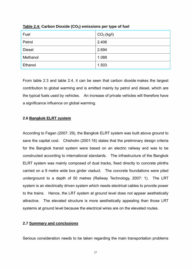
Table 2.4: Carbon Dioxide (CO2) emissions per type of fuel
Fuel CO2 (kg/l)
Petrol 2.406
Diesel 2.694
Methanol 1.088
Ethanol 1.503
From table 2.3 and table 2.4, it can be seen that carbon dioxide makes the largest
contribution to global warming and is emitted mainly by petrol and diesel, which are
the typical fuels used by vehicles. An increase of private vehicles will therefore have
a significance influence on global warming.
2.6 Bangkok ELRT system
According to Fagan (2007: 29), the Bangkok ELRT system was built above ground to
save the capital cost. Chisholm (2001:16) states that the preliminary design criteria
for the Bangkok transit system were based on an electric railway and was to be
constructed according to international standards. The infrastructure of the Bangkok
ELRT system was mainly composed of dual tracks, fixed directly to concrete plinths
carried on a 9 metre wide box girder viaduct. The concrete foundations were piled
underground to a depth of 50 metres (Railway Technology, 2007: 1). The LRT
system is an electrically driven system which needs electrical cables to provide power
to the trains. Hence, the LRT system at ground level does not appear aesthetically
attractive. The elevated structure is more aesthetically appealing than those LRT
systems at ground level because the electrical wires are on the elevated routes.
2.7 Summary and conclusions
Serious consideration needs to be taken regarding the main transportation problems

28
that urban areas are facing today. These problems are: traffic congestion and a lack
of public parking space; limited public space and recreational space; noise and air
pollution; damage to the natural environmental and excessive use of natural
resources for energy usage. In order to accommodate the increasing number of
motor vehicles, more road and cloverleaf junctions have been built to relieve traffic
congestion. However, more roads and cloverleaf junctions cannot solve the adverse
effects caused by high numbers of motor vehicles on the roads. Under the present
circumstances, new and efficient transportation systems are necessary for the current
and future development in large urban centres.
Some successful LRT systems were described in this chapter. Feasibility studies
carried out by the NMBM between 1984 and 1989 showed at the time that LRT would
be suitable as an alternative transport mode to serve the NMB area. The experience
of successful LRT systems show that this success depends greatly on close
integration with the road network, because they are on the same plane and interact
with each other. A conceptual ELRT model can alleviate various transportation
problems due to elevating the track. The exclusive right of way will provide an
efficient and convenient transportation system for both the passengers and the
operating departments.
An analysis of the budgets of some completed LRT projects illustrates that the
construction of an LRT system has the ability to be completed on time and within its
budget. The benefits of LRT are demonstrated in time after commissioning the
system.
While considering the budget of a transportation system, environmental aspects
cannot be neglected. The electricity energy usage of LRT systems can reduce the
use of finite petroleum energy resources and is also air pollution free.
In order to solve its transportation problems, Bangkok built an ELRT system to reduce

29
its severe traffic congestions. The conceptual ELRT model will be more aesthetically
appealing than LRT systems at ground level.
The next chapter focuses on the main civil engineering components of ELRT systems.

30
CHAPTER 3
LITERATURE REVIEW ON THE MAIN CIVIL ENGINEERING
COMPONENTS FOR A CONCEPTUAL ELRT MODEL
3.1 Introduction
Based on the analysis from chapter 2, a conceptual ELRT model can be developed
that will be more efficient and will solve transportation problems. The main civil
engineering components for a conceptual ELRT model will be analysed in this chapter.
The following sections will suggest the most suitable bridge foundation, bridge girder,
and railway sleeper together with an indication whether the track should be a
ballasted or non-ballasted type.
3.2 Main civil engineering components for the conceptual ELRT model
Like other structures, a conceptual ELRT model is also composed of different
components. Essentially, the conceptual ELRT model is composed of bridges and
railway tracks. The bridges are mainly composed of bridge foundations, pillars and
bridge girders. The bridge pillars are not much different from other bridge projects,
because it fulfils the same main function, which is to transfer loads to the foundations.
The differences between various bridge pillars are only their appearance and size and
thus do not need to be discussed in depth. Hence bridge pillars are not dealt with in
this research.
As for bridge foundations, there are several types of foundations for different type of
soils and building structures. Hence, foundations are of vital importance for the
stability of a conceptual ELRT model. Like bridge foundations, various types of

31
bridge girders have special applications. Bridge foundations and bridge girders are
thus discussed in depth in this research to determine the most suitable type of bridge
foundation and bridge girder for a conceptual ELRT model.
Typically LRT systems use steel wheels on steel rails. However, a rubber tyre
system or magnetic levitation system can also be considered as alternatives. The
rubber tyre system is usually used for a monorail system. The elevated rubber tyres
are easily worn down through abrasion, which needs constant maintenances. In
addition, the elevated rubber tyres need special technology to control the direction of
trains along the elevated structures. Therefore, the rubber tyre system will not be
considered in this research. The magnetic levitation system is too expensive to build
and the magnetic levitation technology still needs to be developed. Therefore, this
research only focuses on railway tracks designed for steel wheel on steel rail.
Railway tracks mainly consist of railway sleepers, rails and ballasted or non-ballasted
sleeper bed. Different types of rails are suitable for different railway systems. Rail
specifications do not vary widely for LRT systems and there is thus no need to discuss
them in depth. Sleepers for railway tracks, like the foundations for bridges, are
important for the stability of the railway line. The technology for non-ballasted
railway tracks has developed rapidly in recent years. Therefore, the correct type of
sleepers and whether the track should be a ballasted or non-ballasted will be
discussed in depth in order to determine which type is most suitable for a conceptual
ELRT model. The following section will discuss these main civil engineering
components.
3.2.1 ELRT foundations
The function of a foundation is to form the solid underground base for the building
(Wehmeier, 2000: 499). The ELRT foundations are similar to bridge foundations and
are determined by the type of soils that the foundations are in. However, this

32
research concerns foundations for ELRT and aims at developing the most suitable
foundations for a conceptual ELRT model. Therefore, no detailed soil information
and site investigations are needed because it belongs to the practical design. In this
section, the characteristics of different types of foundations will be introduced.
The assumed ELRT foundation will be determined by comparing the characteristics of
different types of bridge foundations. Through in depth analysis of potential
foundation types, it will be determined which type is the most suitable foundation for a
conceptual ELRT model.
3.2.1.1 Characteristics of different types of foundations
Foundations are separated into several types according to their applications. Each
type of foundation has its own characteristics, which are suitable for different types of
buildings. Four typical foundations are introduced below:
3.2.1.1.1 Pad foundations
According to Tomlinson (2001: 38), pad foundations are invariably provided to support
structural columns which usually consist of a simple circular, square, or rectangular
slab of uniform thickness. In order to distribute the load from a heavy column, these
footings may be stepped or hunched. However, if pad foundations are used for
heavily loaded structural steel columns, a steel grillage will sometimes be needed.
3.2.1.1.2 Strip foundations
Tomlinson (2001: 38) indicates that strip foundations are usually divided into two types.
The first type usually provides for load-bearing walls and the second type normally
provides for rows of columns, which are spaced so closely that the pad foundations
would nearly touch each other. Tomlinson explains that it is more economical for

33
foundations with rows of columns to be excavated and a concrete strip foundation
inserted, than to work in a large number of individual pits. Furthermore, Tomlinson
(2001: 38) points out that if the bearing capacity of the soils is low, wide strip
foundations are recommended.
3.2.1.1.3 Raft foundations
According to Tomlinson (2001: 38), raft foundations are normally used in soils of low
load-bearing capacity, with structural columns, or when other loaded areas are so
close in both directions that individual pad foundations would nearly touch each other.
Tomlinson pointed out that raft foundations are useful to reduce differential settlement
on different types of soils or where the loading varies greatly between adjacent
columns or other applied loads.
3.2.1.1.4 Piled foundations
Bearing piles are required on conditions where the soil that is at normal foundation
level cannot support an ordinary pad, strip, or raft foundation, or where structures are
located on deep filling, which is compressible and settling under its own weight
(Tomlinson, 2001: 38). For the situations where supporting structures are built over
water, or where upward loads must be resisted, piled foundations are a convenient
method to use. Lateral forces are resisted by inclined or raking piles.
3.2.1.2 Bridge foundations
According to Tomlinson (2001: 223), the character of bridge foundations is very
different from that of buildings in terms of foundation loadings. For highway bridges,
imposed loads can be half of the dead load and can be dominant. For railway
bridges, imposed loads account for two-thirds of the dead load. Furthermore, the
moving loads caused by traffic can exert a considerable longitudinal traction force on

34
the bridge deck. Besides moving loads caused by traffic, longitudinal forces are also
caused by shrinkage, temperature changes in bridge decks and wind loading.
3.2.1.2.1 Effect of settlement on bridges
The settlement of bridge foundations plays an important role in the stability of the
bridge. The differential settlements of bridge foundations can induce bending
moments at the junction between the bridge girder and pier. Furthermore, the
differential settlements of bridge foundations can cause unevenness of the surface.
This unevenness of the route surface will impose more moving loads on the bridge,
limit maximum speeds of LRT trains and thus result in instability of the system and
discomfort for passengers. According to Tomlinson (2001: 42), close liaison between
designers of the superstructure and those of the foundation is essential, to avoid
impracticable constraints such as zero settlement in the superstructure design.
Tomlinson (2001: 224) explains that foundation settlements are more critical to the
design of the superstructure than in the case of buildings because of the heavy
moving loads on the highway and rail bridges. Furthermore, Tomlinson (2001: 225)
emphasizes that the limitation of total settlement to 5-10 millimetre (mm) is difficult to
achieve with spread foundations, especially on certain types of soils that have
moderate to low compressibility. Even spread foundations may be taken down
through weak soils to less compressible soils at depth. Tomlinson (2001: 226) points
out that highway and bridge designers are often forced to adopt piled foundations to
reduce settlement to tolerable limits.
According to Tomlinson (2001: 279), piles may settle beyond the maximum allowable
settlement at loads lower than the maximum load that the piles can sustain. When
piles settle beyond their specified allowable settlement, it is regarded as failure of the
piles. Hence, settlement limits and allowable loads are critical aspects in the
selection and design of piles. The effect of settlement is even more critical for the

35
bridge deck and track smoothness.
3.2.1.2.2 Types of pile foundations
Piled foundations are widely used as bridge foundations and they are divided into
several types that are use in different circumstances. According to Tomlinson (2001:
345), piled foundations are typically divided into the following types:
Driven piles:
Timber (round or square sections);
Pre-cast concrete (solid or hollow sections);
Pre-stressed concrete (solid or hollow sections); and
Steel H-section, box and tube piles.
Driven and cast-in place piles:
Withdrawable steel driven tube with end closed by detachable point;
Steel shells driven by withdrawable mandrel or drive tube; and
Pre-cast concrete shells driven by withdrawable mandrel.
Bored piles:
Augered;
Cable percussion drilling;
Large-diameter under-reamed;
Types incorporating pre-cast concrete units;
Drilled-in tubes; and
Mini-piles.
36
Composite piles:
These are a combination of two or more of the preceding types, or a
combination of different materials in the same type of pile.
3.2.1.2.3 Choice of piled foundations
Tomlinson (2001: 387) claims that the foundation should ideally be designed for the
particular conditions at any given point of loading, which requires a very detailed
investigation of soils at a considerable cost. The other alternative is for the
foundations to be designed individually, according to the soil conditions, which are
analysed during the excavation work. This procedure makes any advanced design
or job planning impossible and will delay the time schedule for the project. Hence,
Tomlinson recommends that by adopting pile foundations, the job can be designed
and planned well before construction, regardless whether the soil is in a good or bad
condition. Furthermore, Tomlinson explains that by adapting a safety factor, piles in
bad ground conditions have very small settlements and the relative settlements can
be negligible. These results could be difficult to be achieved with pad foundations.
The characteristics of piled foundations makes piled foundations most suitable for a
conceptual ELRT model.
3.2.1.2.4 Advantages and disadvantages of types of pile foundations
Each type of pile foundation has its own applications according to specific conditions.
Tomlinson (2001: 387) summarizes the various types of pile foundations in detail and
gives their particular application as follows:
a) Driven piles
Tomlinson (2001: 387) explains that the advantages of driven piles are as follows:

37
Materials of piles can be inspected before they go into the ground.
They are stable in ‘squeezing’ ground.
They do not get damaged by ground heave when driving adjacent piles.
Construction procedure unaffected by ground water.
Can be readily carried above ground level, especially in marine structures.
Can be driven in very long lengths.
However, Tomlinson (2001: 387) explains that the disadvantages of driven piles
include:
They may break during hard driving causing delays and replacement charges,
or worse still, they may suffer major unseen damage in hard driving
conditions.
They are uneconomical if the amount of material in the piles is governed by
handling and driving stresses rather than by stresses from permanent loading.
Noise and vibration during driving may cause nuisance or damage.
Displacement of soil when driving piles in groups may damage adjacent
structures or cause lifting by ground heave of adjacent piles.
End enlargements are not always advantageous.
They cannot be driven in conditions of low headroom.
The characteristics of driven piles, as described by Tomlinson show that they are not
suitable for a conceptual ELRT model. The main problem with driven piles is that
they engender noise and vibration during construction which will produce
environmental pollution in the area. Situations of low headroom also restrict the use
of driven piles because the construction must take place mainly in a built up
environment with business and residential development close to the proposed route.
The headroom of a bridge in urban areas is typically 6 meters to provide the least
amount of interference to the existing traffic at ground level (Erie Community College

38
(ECC), 2007: 21).
b) Driven and cast-in-place piles
Tomlinson (2001: 387) states that the advantages of driven and cast-in-place piles are
as follows:
Their length can be readily adjusted to suit varying levels of bearing stratum.
The tube is driven with a closed end, thus excluding ground water.
It is possible to form an enlarged base in some types.
The material in these piles is not affected by handling or driving stresses.
Noise and vibration can be reduced in some types.
They do not produce surplus spoil.
Nevertheless, Tomlinson (2001, 388) states that the disadvantages include:
‘Necking’ or ‘waisting’ may occur in squeezing ground unless great care is
taken when concreting the shaft.
Concrete shafts may be weakened if strong artesian water-flow pipe up
outside of the shaft.
Concrete cannot be inspected after completion.
Limitations of length of driving in most types.
Displacement of ground may damage ‘green’ concrete of adjacent piles, or
cause lifting by ground heave of adjacent piles.
Noise, vibration, and ground displacement may cause a nuisance or damage
adjacent structures.
They cannot be used in river or marine structures without special adaptation.
They cannot be driven in conditions of very low headroom.
Based on Tomlinson’s explanation for driven and cast-in-place piles, they also not
39
suitable for the conceptual ELRT model. Noise, vibration and ground displacement
may cause damage to adjacent structures, which means that this type of foundation is
not suitable for urban areas. This type of foundation cannot be constructed in places
where there is low headroom because the headroom of bridges in urban areas is
typically 6 meters, to provide the least amount of interference to traffic at ground level
(ECC, 2007: 21).
c) Bored and cast-in-place piles
Tomlinson (2001: 388) describes the advantages of bored and cast-in-place piles as
follows:
Length can be readily varied to suit varying ground conditions.
Soil removed in boring can be inspected and if necessary sampled or an
in-situ test can be done.
They can be installed in very large diameters.
End enlargements up to two or three diameters are possible in clay.
The material of the piles is not dependent on handling or driving conditions.
They can be installed in very long lengths.
They can be installed without much noise or vibration.
They can be installed in conditions of very low headroom.
They present no risk of ground heaves.
While Tomlinson (2001: 388) further points out the disadvantages as follows:
They are susceptible to ‘waisting’ or ‘necking’ in ‘squeezing’ ground.
Concrete is not placed under ideal conditions and cannot be inspected after
construction.
Water under artesian pressure may pipe up the pile shaft, washing out the
cement.

40
Enlarged ends cannot be formed in coarse materials without special
techniques.
They cannot be readily extended above ground level especially in river and
marine structures.
Boring methods may loosen sandy soils or gravel requiring base grouting to
achieve economical base resistance.
Sinking piles may cause loss of ground in coarse soils, leading to settlement
of adjacent structures.
Surplus spoils may be produced with additional cost of transporting from site.
The limitations of driven piles and driven and cast-in-place piles make bored and
cast-in-place piles the most suitable foundation type for bridge foundations for the
conceptual ELRT model. Large diameters and long lengths provide enough bearing
capacity to stabilize the bridges for the conceptual ELRT model. Lower noise during
construction makes this type of pile more suitable for use in urban areas. In addition,
bored and cast-in-place piles can be installed with low headroom which can save the
materials used in bridge pillars. Varghese (2005: 254) states that bored and
cast-in-place piles are much preferred for use in cities, as they do not cause any
disturbance to the surroundings.
3.2.1.2.5 Specific application for each type of piles
Tomlinson (2001: 388) described three different types of piles as follows:
Firstly, the driven piles are typically divided into timber, concrete and steel driven piles
in terms of the materials that are used. The specific applications of three types of
driven piles are introduced by Tomlinson as follows:
Timber-driven piles are suitable for light loads or temporary works. However,
timber-driven piles are unsuitable for heavy loads. Because of the
41
fluctuating water table, this type of foundation is subject to decay. If driven
too heavily, this type of foundation is liable to unseen splitting damage.
Concrete-driven piles are suitable for all ranges of loading and can be
designed to be suitable for corrosive soil conditions. Concrete driven piles
have the ability to adapt to various sizes and shapes. However, additional
reinforcement must be used to provide enough strength for handling and
driving stresses. This type of foundation is liable to unseen damage under
heavy driving, causing delay between casting and driving.
A steel-driven pile is also suitable for all ranges of loading and can readily be
cut down or extended. The parts that are cut off can be used for extending
other piles. When driven hard, steel-driven piles will not damage and can be
driven in very long lengths by welding on additional lengths. Some types
cause minor displacement of ground. Structural steel bracing can be welded
or bolted on. Steel-driven piles are suitable for jetty structures. However,
the main disadvantage of steel-driven piles is that they are subject to
corrosion above the soil line, especially in marine structures. In addition,
long and slender piles are liable to go off line during driving.
Secondly, driven and cast-in-place piles have withdrawable tubes which make them
cheaper than piles where steel or concrete tubes or shells are left in the ground.
However, those with tubes or shells in the ground are a sounder form of construction
for ‘squeezing’ soils or water-bearing sands or where redriving is necessary following
ground heave.
Thirdly, bored and cast-in-place piles are the cheapest form of piles and are simple,
mechanically auger piles sunk without any casing. However, they are only suitable
for reasonably firm to stiff cohesive soils. The cost varies when a casing has to be
installed and withdrawn, and slower conventional boring methods must be used.
The use of continuous flight auger piling reduces problems with casings. In addition,
the use of drilling with continuous flight augers or under bentonite slurry has overcome

42
many of the problems associated with ground water and the loosening of granular
soils.
According to the experience reported by Tomlinson (2001: 388), it is usual that
headroom conditions restrict the selection of the type of pile. ECC (2007: 21) points
out that the headroom of a bridge in urban areas is typically 6 meters. Bored and
cast-in-place piles are therefore providing a reasonable foundation type for the
conceptual ELRT model.
3.2.1.3 Analysis of bored and cast-in-place piles in different types of soils
Different types of soils have different characteristics and have different carrying
capacities for structures. Hence, it is important to understand the different types of
soils, because they will affect the design and application of bored and cast-in-place
piles for various situations for the conceptual ELRT model. 3.2.1.3.1 General soil types
According to Liu and Event (2004: 9), soils may be broadly divided into three
categories: 1) non-cohesive, 2) cohesive and 3) organic soils. Each type has its own
properties as shown in the following section.
a) Non-cohesive soils
Liu and Event (2004: 9) point out that one the main characteristics of non-cohesive
soils are that the particles tend not to stick together. Gravel, sand and silt are three
common types of non-cohesive soils which are differentiated by particle size. The
particle size of gravel is greater than 2 mm, whereas the sizes for sand range between
0.1 to 2 mm. Furthermore, both gravel and sand may be divided into fine (fine sand)
and coarse (coarse sand). However, the range of particle size for silt is from 0.005 to
43
0.1 mm.
b) Cohesive soils
According to Liu and Event (2004: 9), cohesive soils have a very small particle size
and the particles tend to stick together. This characteristic is the result of
water-particle interaction and attractive forces between particles. Hence, cohesive
soils are sticky and plastic. The most common type of cohesive soil is clay, which
has a particle size less than 0.005 mm. Liu and Event claims that clayey soils cannot
be separated by sieve analysis because no practical sieve can be made small enough.
Through observing setting velocities1 of the particles in a water mixture, the particle
sizes can be determined (Liu and Event, 2004: 9).
c) Organic soils
Liu and Event (2004: 9) explains that the identities of organic soils are typically spongy,
crumbly and compressible. These characteristics make organic soils unsuitable for
supporting structures.
Soils can also be strictly divided into coarse-grained and fine-grained soils according
to their grain size for foundation design purposes.
3.2.1.3.2 Soil types by grain size
According to Liu and Event (2004: 9), soils can also be categorized strictly in terms of
grain size. Gravel and sand with soil grains coarser than 0.075 mm belong to
coarse-grained soils. Silt and clay with soil grains finer than 0.075 mm belong to
fine-grained soils.
1 A method to determine particle sizes of cohesive soils
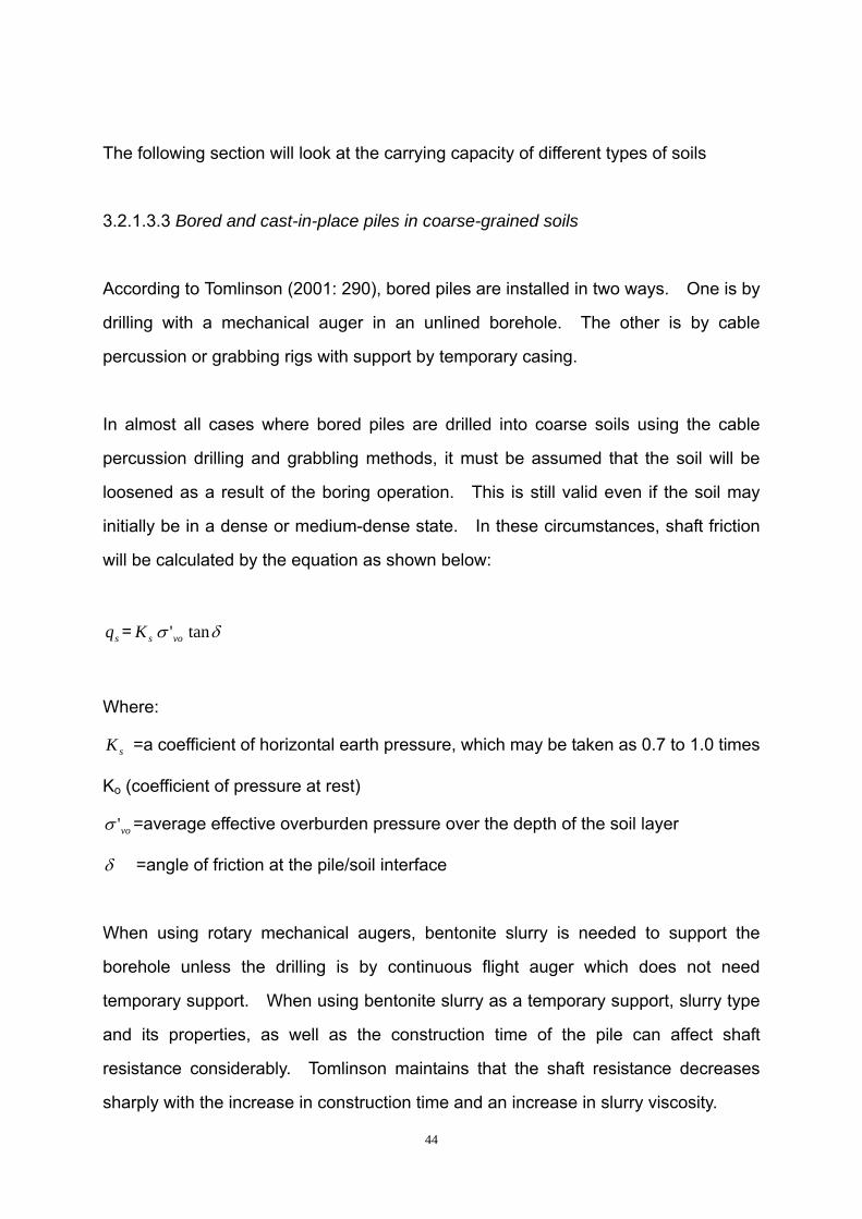
44
The following section will look at the carrying capacity of different types of soils
3.2.1.3.3 Bored and cast-in-place piles in coarse-grained soils
According to Tomlinson (2001: 290), bored piles are installed in two ways. One is by
drilling with a mechanical auger in an unlined borehole. The other is by cable
percussion or grabbing rigs with support by temporary casing.
In almost all cases where bored piles are drilled into coarse soils using the cable
percussion drilling and grabbling methods, it must be assumed that the soil will be
loosened as a result of the boring operation. This is still valid even if the soil may
initially be in a dense or medium-dense state. In these circumstances, shaft friction
will be calculated by the equation as shown below:
sq = sK vo'σ δtan
Where:
sK =a coefficient of horizontal earth pressure, which may be taken as 0.7 to 1.0 times
Ko (coefficient of pressure at rest)
vo'σ =average effective overburden pressure over the depth of the soil layer
δ =angle of friction at the pile/soil interface
When using rotary mechanical augers, bentonite slurry is needed to support the
borehole unless the drilling is by continuous flight auger which does not need
temporary support. When using bentonite slurry as a temporary support, slurry type
and its properties, as well as the construction time of the pile can affect shaft
resistance considerably. Tomlinson maintains that the shaft resistance decreases
sharply with the increase in construction time and an increase in slurry viscosity.
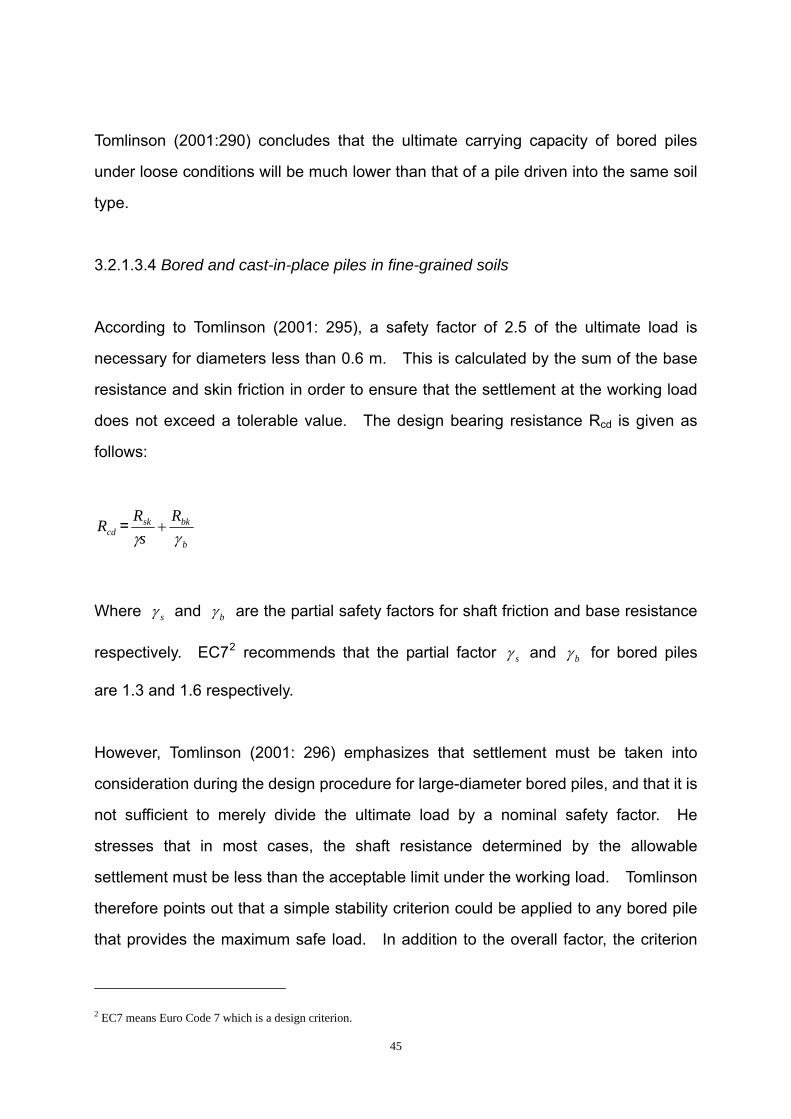
45
Tomlinson (2001:290) concludes that the ultimate carrying capacity of bored piles
under loose conditions will be much lower than that of a pile driven into the same soil
type.
3.2.1.3.4 Bored and cast-in-place piles in fine-grained soils
According to Tomlinson (2001: 295), a safety factor of 2.5 of the ultimate load is
necessary for diameters less than 0.6 m. This is calculated by the sum of the base
resistance and skin friction in order to ensure that the settlement at the working load
does not exceed a tolerable value. The design bearing resistance Rcd is given as
follows:
cdR =b
bksk Rs
Rγγ
+
Where sγ and bγ are the partial safety factors for shaft friction and base resistance
respectively. EC72 recommends that the partial factor sγ and bγ for bored piles
are 1.3 and 1.6 respectively.
However, Tomlinson (2001: 296) emphasizes that settlement must be taken into
consideration during the design procedure for large-diameter bored piles, and that it is
not sufficient to merely divide the ultimate load by a nominal safety factor. He
stresses that in most cases, the shaft resistance determined by the allowable
settlement must be less than the acceptable limit under the working load. Tomlinson
therefore points out that a simple stability criterion could be applied to any bored pile
that provides the maximum safe load. In addition to the overall factor, the criterion
2 EC7 means Euro Code 7 which is a design criterion.

46
stipulates that a factor of safety in end-bearing must be sufficient in general terms.
For example, if an overall load factor of 2, together with a minimum end-bearing factor
of 3 is stipulated, then the maximum safety load is the lesser of the two expressions
below:
2ultQ for the pile
and
ultQ for the shaft3ultQ
+ for the base.
If the soil data are meagre or variable, or when the loads are indeterminate, an overall
load factor of 2.5 with a minimum factor of 3.5 on the base is more suitable for
application.
3.2.1.4 Effects of horizontal or inclined loads on foundation piles
Tomlinson (2001: 314) states that foundation piles frequently carry incline loads that
come from the dead load of the structure and also horizontal loads such as wind,
water pressure or earth pressure. The effects of horizontal or inclined loads to piles
will be discussed below:
3.2.1.4.1 Effects of horizontal or inclined loads on short piles
Tomlinson (2001: 315) states that the full value of skin friction on the shaft should not
be allowed where the lateral loading is intermittent, as in the case of bridge trestles.
Lateral loads have a deep effect on short piles3, either in stiff clays or in soft clays, silts,
or sands and gravels. Intermittent lateral loadings cause deflection and rebound to
short piles in stiff clays, and for this reason the enlarged hole for the pile reduces the
3 Typically, short piles refer to those lengths to width ratio less than 10-12.

47
friction. This causes the carrying capacity to be based on the end-bearing only.
However, in case of piles in soft clays, silts, or sands and gravels, intermittent lateral
loadings cause remoulded shear strength, but soft clays or silts may still be used for
skin friction. Under these circumstances the low value of skin friction in sands and
gravels themselves should be taken into account.
In the case of horizontal load being applied on a pile, a short rigid pile will rotate and
passive resistance will occur at the head and toe and near the ground surface
(Tomlinson, 2001: 315).
3.2.1.4.2 Effects of horizontal or inclined loads on long piles
Compared to short piles, the failure mechanism of a long pile is different because the
cumulative passive resistance at the lower part of the pile is very high, which makes it
impossible for the pile to rotate. Failure should occur at the point of maximum
moment of a pile (Tomlinson, 2001: 315).
Due to rotation or fracture of the pile, the head of the pile under a lateral load will move
a considerable distance before it is damaged (Tomlinson, 2001: 316). Then, the
moment of the upper parts of the bridge which are supported by the pile, may exceed
the tolerable limit and will affect the stability of the bridge and in turn endanger the
stability of the railway track.
From the analysis above, long piles are more suitable to provide stable structures. If
the conditions permit, it is better that the pile is driven to a hard unyielding stratum
which makes the settlement of the foundation almost equal to zero. Hence, the
impact on the bridge foundation will only be limited to the shrinkage of the pile due to
the compression.
Typically, in most practical projects, the piled foundations are arranged four piles to a

48
H H
V1 V2
M
ground level
A
pillar. It is depicted diagrammatically from a mechanical point of view in figure 3.1
below:
Figure 3.1: Comparison of single pile and pile group under horizontal loads
Figure 3.1 shows the cross section of a single pile and a four pile group under
horizontal load H. By comparing the forces on each of these, a single pile provides
the shearing force and bending moments M while the pile group provides shearing
force, tension V2 and compression V1 under the effect of H. Under horizontal load H,
a single pile may be broken at the point of A and move as shown by the broken line.
Due to the property of reinforced concrete, a pile can resist more tension and
compression than bending moments. Hence, pile groups are more stable than a
single pile.
3.2.2 ELRT girders
According to Wehmeier (2000: 499), a girder is a long strong beam used for bridges
and the framework of large buildings. Nowadays, many bridge girders have
reinforced concrete to reduce the cost and self-weight and to have greater carrying
capacity. Typically, bridges are divided into several types as follows (Schulz, 2002:
16):
49
Drainage/culvert;
Arch;
Beam;
Box girder;
Suspension;
Cable-stayed;
Truss;
Cantilever;
Movable; and
Covered.
According to Bonnett (2001: 113), a characteristic of concrete is that the compression
strength is about ten times that of tension strength. Steel has more tensile strength
while concrete has more compression strength. The cost of concrete is much less
than that of steel. Reinforced concrete use concrete for compression and reinforcing
steel bars for tension. For these reasons, reinforced concrete girders can greatly
reduce the cost of bridge girders without diminishing the maximum carrying capacity.
Furthermore, Bonnett (2001: 113) points out that reinforced concrete can overcome its
deficiency in tension simply by adding reinforced steel bars where tension is likely to
occur. One other advantage of reinforced concrete girders over steel girders is that
the concrete in the reinforced concrete girder prevents the steel bars from rusting if
there is enough concrete cover. The steel bars therefore do not need special
protection outside the girder to prevent them from rusting. Due to cost and durability
factors, reinforced concrete girders are suitable for use in the conceptual ELRT
model.
Railway bridges need to be very stiff, therefore cable stayed or suspension systems
are usually inappropriate (University of Portsmouth, 2003: 1). Railway bridges are
typically divided into simple supported bridges and continuous bridges, according to
their structural modalities. Continuous bridges need to be constructed in situ where

50
many support implements and construction vehicles are needed. These implements
and vehicles will occupy a wide area of space near the construction site. For simple
supported bridges, the bridge girders are prefabricated in bridge girder factories and
conveyed to the construction site for installing. For ease of design procedures,
construction procedures, and few disturbances in the existing transportation systems,
simple supported bridges are comparatively the best solution for the conceptual ELRT
model.
Steel girders usually make use of a truss framework to reduce their self-weight and
further to reduce the cost through reducing the quantity of materials that are used.
For the same reason, reinforced concrete girders use different forms of cross-section
to reduce their own weight and material costs without reducing the maximum carrying
capacity in supporting the loads from the top. Usually, bridge girders have to resist
bending moment, shearing force and torsional moment.
Priestley et al (cited in Rodriguez, 2005: 7) show the typical sectional shapes for
bridge superstructures as in the table 3.1 below:
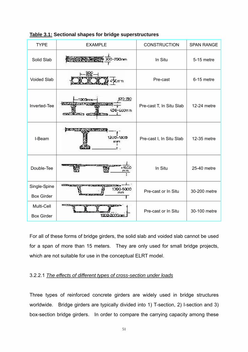
51
Table 3.1: Sectional shapes for bridge superstructures
TYPE EXAMPLE CONSTRUCTION SPAN RANGE
Solid Slab
In Situ 5-15 metre
Voided Slab
Pre-cast 6-15 metre
Inverted-Tee Pre-cast T, In Situ Slab 12-24 metre
I-Beam
Pre-cast I, In Situ Slab 12-35 metre
Double-Tee In Situ 25-40 metre
Single-Spine
Box Girder Pre-cast or In Situ 30-200 metre
Multi-Cell
Box Girder Pre-cast or In Situ 30-100 metre
For all of these forms of bridge girders, the solid slab and voided slab cannot be used
for a span of more than 15 meters. They are only used for small bridge projects,
which are not suitable for use in the conceptual ELRT model.
3.2.2.1 The effects of different types of cross-section under loads
Three types of reinforced concrete girders are widely used in bridge structures
worldwide. Bridge girders are typically divided into 1) T-section, 2) I-section and 3)
box-section bridge girders. In order to compare the carrying capacity among these

52
FW
Girder
pier pier
three types of girder forms, an analysis of structural mechanics is needed.
Figure 3.2 below illustrates the example of a reinforced concrete girder experiencing
uniformly distributed loads W and a central point load F:
Figure 3.2: Sketch for analysis of a simply-supported girder under loads
Two loads can be identified on the girder and they are indicated by the letters F and W.
According to Orton (1988: 101), the maximum bending moment under uniformly
distributed loads W is at the central point of the girder. The maximum bending
moment under central point load F also happens at the central point of the girder as
shown below:
8.LWM cud = and
4.LFM ccp =
Where cudM and ccpM account for the maximum bending moments caused by
uniformly distributed loads W and central point load F respectively.
L is the length of the girder.
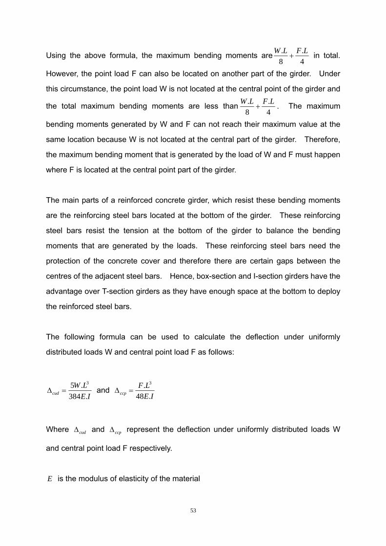
53
Using the above formula, the maximum bending moments are4.
8. LFLW+ in total.
However, the point load F can also be located on another part of the girder. Under
this circumstance, the point load W is not located at the central point of the girder and
the total maximum bending moments are less than4.
8. LFLW+ . The maximum
bending moments generated by W and F can not reach their maximum value at the
same location because W is not located at the central part of the girder. Therefore,
the maximum bending moment that is generated by the load of W and F must happen
where F is located at the central point part of the girder.
The main parts of a reinforced concrete girder, which resist these bending moments
are the reinforcing steel bars located at the bottom of the girder. These reinforcing
steel bars resist the tension at the bottom of the girder to balance the bending
moments that are generated by the loads. These reinforcing steel bars need the
protection of the concrete cover and therefore there are certain gaps between the
centres of the adjacent steel bars. Hence, box-section and I-section girders have the
advantage over T-section girders as they have enough space at the bottom to deploy
the reinforced steel bars.
The following formula can be used to calculate the deflection under uniformly
distributed loads W and central point load F as follows:
IELW
cud .384.5 3
=Δ and IE
LFccp .48
. 3
=Δ
Where cudΔ and ccpΔ represent the deflection under uniformly distributed loads W
and central point load F respectively.
E is the modulus of elasticity of the material

54
I is the moment of inertia.
In the formula shown above, the bending moment is related to parameters E and I
if the loads on the girder are the same. E is the modulus of elasticity of the material,
therefore it relates to the materials of which the girders are made of. Hence, the
bearing capacity of maximum deformation relates to the moment of inertia I .
According to Chen (1995: 1396), the moment of inertia zI can be calculated as
follows:
zI dAyA∫=
2
Hence, the moment of inertia I relates to the cross-sectional area. The next
section will discuss the moment of inertia among different types of girder forms.
3.2.2.1.1 Analysis of the moment of inertia for three forms of cross-section
Figure 3.3 below gives the dimensions of T, I and the box cross-section. These units
are all indicated in centimetres (cm):
Figure 3.3: Comparison of three different cross-sectional forms

55
y
ycc
I
II
z1
z
As shown in Figure 3.3, the widths of the upper part of the three forms are the same
because an ELRT girder needs the same space to support both the railway tracks and
the additional bridge facilities on the girders. The areas of these three forms are
identical, which ensures that the self-weight of the three forms of girder are the same,
provided that the three girders are made of the same concrete and reinforcing steel
bars.
In order to compare the moment of inertia for the three forms of cross-sections,
calculations of the moment of inertia among these three forms are needed.
Firstly, it is necessary to calculate the moment of inertia of T cross-sectional form as
the figure 3.4 shows below:
Figure 3.4: Analysis of the moment of inertia of T cross-sectional form

56
The centre of the figure, ( c ), must be determined before calculating the moment of
inertia. Firstly, it is necessary to divide the T-section into two rectangle sections I
and II as shown in figure 3.4 above. These two sections are symmetrical among
the z axis, hence the centre of the figure c must be along the z axis. Nie and
Meng (2004: 413) demonstrated the calculation as follows: ∑
∑
=
== n
ii
n
iii
A
yAy
1
1 , hence the
distance 1z between the horizontal axis y and cy can be calculated as follows:
21
22111
..AA
yAyAz++
=
=37310
5370310×+×
××+××
= m056.2
The location of the central point of the figure was fixed. Next, the moment of inertia
yI will be calculated according to the formula 12
3bhI y = (Nie & Meng 2004: 415) and
AaII yy2
1 += (Nie & Meng 2004: 416).
21)056.25(7312130056.2310
121 2323 ×−+××+×+××=yI
010.18275.85814.1265.22 +++=
3074.417 m=
Secondly, it is necessary to calculate the moment of inertia of the I cross-sectional
forms as figure 3.5 shows:

57
y
z
Figure 3.5: Analysis of the moment of inertia of I cross-sectional form
The location of the central point of the figure must be in the middle of this
cross-section because it is symmetrical along the vertical axis z and the horizontal
axis y . Hence, the moment of inertia of the I cross-sectional form is calculated as
follows:
323 731212]15)75.05.3(5.110
121[ ××+××++××=yI
75.855.547 +=
325.633 m=
Thirdly, it is necessary to calculate the moment of inertia of the box cross-sectional
forms as the figure 3.6 shows:

58
Figure 3.6: Analysis of the moment of inertia of box cross-sectional form
With the same principle as in the I cross-sectional form, the central point of the figure
is also in the middle of this cross-section. Hence, the moment of inertia of the box
cross-sectional form is calculated as follows:
275.11212]15)75.05.3(5.110
121[ 323 ×××+××++××=yI
75.855.547 +=
325.633 m=
By calculating the moment of inertia for these three forms of cross-section, the results
concerning the moment of inertia show that the forms of the I-section and box-section
are larger than that of the T-section. From the formula IE
LWcud .384
.5 3
=Δ and
IELF
ccp .48. 3
=Δ , it can be seen that if the moment of inertia is larger, the deformation of
the girder is smaller. Hence, the I-section and the box-section types have an
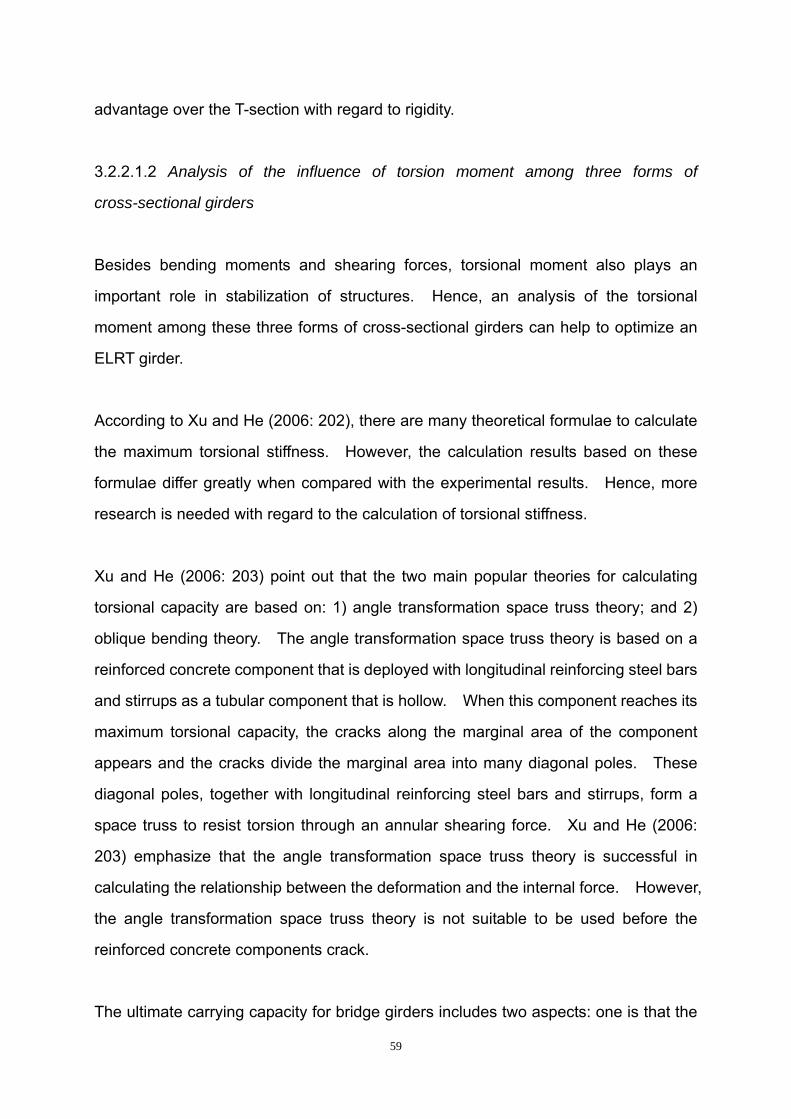
59
advantage over the T-section with regard to rigidity.
3.2.2.1.2 Analysis of the influence of torsion moment among three forms of
cross-sectional girders
Besides bending moments and shearing forces, torsional moment also plays an
important role in stabilization of structures. Hence, an analysis of the torsional
moment among these three forms of cross-sectional girders can help to optimize an
ELRT girder.
According to Xu and He (2006: 202), there are many theoretical formulae to calculate
the maximum torsional stiffness. However, the calculation results based on these
formulae differ greatly when compared with the experimental results. Hence, more
research is needed with regard to the calculation of torsional stiffness.
Xu and He (2006: 203) point out that the two main popular theories for calculating
torsional capacity are based on: 1) angle transformation space truss theory; and 2)
oblique bending theory. The angle transformation space truss theory is based on a
reinforced concrete component that is deployed with longitudinal reinforcing steel bars
and stirrups as a tubular component that is hollow. When this component reaches its
maximum torsional capacity, the cracks along the marginal area of the component
appears and the cracks divide the marginal area into many diagonal poles. These
diagonal poles, together with longitudinal reinforcing steel bars and stirrups, form a
space truss to resist torsion through an annular shearing force. Xu and He (2006:
203) emphasize that the angle transformation space truss theory is successful in
calculating the relationship between the deformation and the internal force. However,
the angle transformation space truss theory is not suitable to be used before the
reinforced concrete components crack.
The ultimate carrying capacity for bridge girders includes two aspects: one is that the

60
girders reach their carrying capacity and the other is that the girders reach their
deformation limit. Hence, the angle transformation space truss theory is suitable for
the calculation of the torsional capacity of girders. Based on this theory, Xu and He
(2006: 205) give the suitable formulae to calculate the torsional capacity of a T-section,
an I-section and a box-section of a reinforced concrete component.
In order to analyse the resistance of torsional moment to distinguish among these
three forms of cross-sectional girders, the same cross-sectional dimensions, which
were used for analysing the bending moments in the previous section are used again.
Xu and He (2006: 205) give the torsional capacity for box cross-sectional components
as follows:
sAAfWfaT st
yvtthucot1.2.135.0 ξ+= .
Where: ha is the effect coefficient of the box-section that equals to 2.5 wt / hb . When
ha >1.0, ha equals 1.0;
wt is the thickness of wall that belongs to the box-section;
hb is the width of the box-section;
tf is the concrete intensity of the axial tension resistance; and
tW is the resistance of torsional moment.
The right part of equation was divided into two parts, one is the torsional resistance by
concrete and the other is the torsional resistance by reinforcing steel bars and stirrups.
The part of sAAf st
yvcot1.2.1 ξ represents the longitudinal steel bars and stirrups which
are resisting the torsional moment. This part of the formula is related to the
deployment of the reinforced steel bars which are determined by the grade of steels

61
used. Hence, the support by steel bars does not directly relate to the cross-sectional
forms, which will not be discussed herein. The part of tth Wfa35.0 represents the
concrete section resistance to the torsional moment. The symbol tf relates to the
property of concrete and the numerical values, which are equal if the grades of
concrete are the same. The symbol tW is the resistance of torsional moment and is
related to the cross-sectional shape.
The parameter that determines the maximum torsional resistance of concrete is the
resistance of torsional moment tW , and the distinctions among these three forms of
cross-sectional girder were determined by tW . Hence tW needs to be calculated in
order to analyse the maximum torsional resistance for these three forms of
cross-sectional girder.
Firstly, it is necessary to calculate the torsional resistance moment of box
cross-sectional forms.
According to Xu and He (2006: 205), the formula for calculating the resistance of
torsional moment for the box-section is given as follows:
)]2(3[6
)2()3(6
22
whwwh
hhh
t tbhtbbhbW −−−
−−=
For easy understanding, each symbol for calculating the box cross-sectional form is
shown in figure 3.7:

62
Figure 3.7: Meaning of symbols in box cross-sectional form
Then, the resistance of the torsional moment is calculated as follows:
)]2(3[6
)2()3(6
22
whwwh
hhh
t tbhtbbhbW −−−
−−=
)]5.1210(73[6
)5.1210()10103(6
10 22
×−−××−
−−×=
333.114333.333 −=
3219m=
Secondly, it is necessary to calculate the resistance of the torsional moment of the T
cross-sectional forms.

63
b'f
b
h
h'f
Xu and He (2006: 206) give the formula to calculate the resistance of the torsional
moment for the T-section as follows:
)'(2'
)3(6
22
bbh
bhbW ff
t −+−=
The meaning of each symbol in this equation is shown in figure 3.8 as follows:
Figure 3.8: Meaning of symbols in T cross-sectional form
Then,
)(2'
)3(6
22
bbh
bhbW ff
t −+−=
)310(23)3103(
63 22
−+−×=
5.315.40 +=
372m=
Thirdly, it is necessary to calculate the resistance of the torsional moment of the I
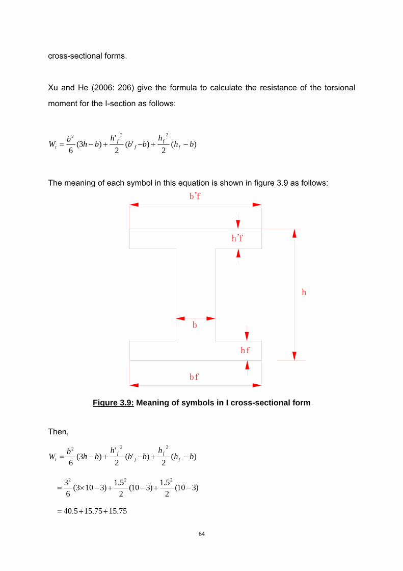
64
b'f
b
h
h'f
hf
bf
cross-sectional forms.
Xu and He (2006: 206) give the formula to calculate the resistance of the torsional
moment for the I-section as follows:
)(2
)'(2'
)3(6
222
bhh
bbh
bhbW ff
ff
t −+−+−=
The meaning of each symbol in this equation is shown in figure 3.9 as follows:
Figure 3.9: Meaning of symbols in I cross-sectional form
Then,
)(2
)'(2'
)3(6
222
bhh
bbh
bhbW ff
ff
t −+−+−=
)310(25.1)310(
25.1)3103(
63 222
−+−+−×=
75.1575.155.40 ++=

65
372m=
The results from calculating the resistance of the torsional moments among the three
forms of cross-sectional components show that the box-section can resist torsion
moments much better than that of the T- and I-sections. Hence box cross-sectional
component have an advantage of torsion resistance over the T and I cross-sectional
components. Bonnett (2001: 109) also conforms that the box-section is torsionally
much stiffer than an I-section.
The foregoing calculations analyses the bending moment and torsional moment of
these three forms of cross-section under the same self-weight. By comparing the
moment of inertia between these three forms of cross-section, the I-section and the
box-section are of greater bending resistance than that of the T-section. The
torsional moment analysis shows that the box section has greater torsional resistance
than the other two forms of cross-sections. Hence, the analyses of the girders are
affected by the loads. The box-section girder is the best form among these three
forms of cross-sectional girders because it is able to resist the loads on the girder
more efficiently.
3.2.2.2 Analysis of box girders
The previous analysis concerning the load effects on the girders indicate that the box
girder has the advantage over the other two forms of bridge girders from a theoretical
perspective. Rodriguez (2005: 6) mentions that the advantage of box girders is that
they have high stiffness and strength with minimum weight and they can be used for
medium and long spans. According to Caltrans (cited in Rodriguez, 2005:6), both
open soffit structures (T-Beams and I-Girders) and box girders present different yet
effective widths in resisting longitudinal seismic moments of superstructures. The
effective width for girders with section of open soffit shapes is smaller than that of

66
corresponding box girders because the shape of the former section offers less
resistance to the torsional rotation of the bent cap.
Ma, Tadros and Sun (2004: 80) state that in North America pre-cast and pre-stressed
concrete box girders are widely used in short-span and medium-span bridges. They
state that pre-stressed concrete bridges account for approximately 50 percent of
bridges built in the USA, and one-third of these are pre-cast box girder structures.
Hence, box girders have a great value in practical application. In the following
section, some previous studies on box girders will be presented in order to determine
a suitable form of box girder for the conceptual ELRT model. The box girder bridge
is shown in figure 3.10 below:
Figure 3.10: Box Girder Bridge
[Source: Schulz, D. (2002: 20). Waterways & Bridges.]
3.2.2.2.1 Some forms of box girders used in America
In the 1950s, new forms of box girder bridges emerged and the most common form
consisted of box sections that were placed adjacent to each other and these adjacent
box girder bridges generally performed very well (Ma, et al., 2004: 81).

67
Ma, et al. (2004: 80) state that the most common box girder systems used in the USA
are the standard AASHTO4 box girder, the U-shaped girder with cast-in-place deck,
and the trapezoidal segmental box system. They analysed the advantages of these
three types of box girders as follows.
a) AASHTO box girder
Ma, et al. (2004: 81) report that in order to save construction time and make the
construction economical, the standard AASHTO box girders are usually built as
non-composite structures, which lead to the deck and do not need to be placed and
cured. In addition, the adjacent box girder bridges have the consistent soffits and a
wide range of span-to-depth ratio, which makes this form of box girder bridges more
practical.
However, Ma, et al. (2004: 81) point out that this form of box girder is not efficient
during the production process. The reason for this is because the void forms must
be left in place, unless using the removable collapsible forms, which are expensive
and time consuming to remove. In addition, Ma, et al. (2004: 81) mention that the
adjacent box girder bridges suffer reflective longitudinal cracking at the top directly
over the longitudinal joints. This cracking causes water leakage, concrete staining,
concrete spalling and corrosion that are not suitable for the stability of the bridge
girders, especially for long term usage.
b) U-shaped girder with cast-in-place deck
Ma, et al. (2004: 81) state that a U-shaped girder, with a cast-in-place deck, is a good
system that is widely used in Oregon, Washington, Texas and other states in America.
4 American Association of State Highway and Transportation Officials

68
The void forms in this type of girder are easily removed. However, the cast-in-place
decks need to be formed in the field, which adds to the cost and construction time.
For some large U-shaped girders, the self-weight is so heavy that transport costs may
increase significantly.
c) Trapezoidal segmental box system
According to Ma, et al. (2004: 81), the trapezoidal segmental box system was
developed by a joint committee of the Pre-cast/Pre-stressed Concrete Institute (PCI)
and the American Segmental Bridge Institute (ASBI). This system is approved by
AASHTO, was put into use several years before 2004, and gained widespread
acceptance. Ma, et al. (2004: 81) state that the advantage of the trapezoidal
segmental box system is that the girders can span up to 200 feet (61 m) and can be
used for most bridge spans. In addition, this system is also aesthetically appealing.
Because of the form costs, production complexity and specialized erection equipment,
this type of system is limited to large projects with enough segment and span
repetition to justify mobilization (Ma, et al., 2004: 81).
Ma, et al. (2004: 81) describe the standard AASHTO-PCI-ASBI segment as being
limited to about 10 feet (3 m) and with a mass of 40 tons. During the construction
procedure, temporary support is needed until the post-tensioned girder is erected,
because of the short segment length. However, the simple false work will disrupt
traffic and make the system unfeasible. Ma, et al. (2004: 81) explain that a solution
for this was to use a special assembly truss, spanning between the adjacent piers. If
the system does not include considerable repetition of the special assembly truss, this
solution is not economical.
For the conceptual ELRT model, the trapezoidal segment box system seems to be the
best of the three box girders because the whole route is elevated allowing for the
possibility of considerable repetition of spans. Ma, et al. (2004: 89) conclude that by

69
assembling the segmental post tensioned box girder to a span-length, the erection
stage would be greatly simplified, especially when it is compared to traditional
methods.
3.2.2.2.2 A technique used for the construction of box girders
According to ECC (2007: 16), the tallest viaduct in Asia, named the Panvel Nadi
viaduct, was completed in 1994. This viaduct, in which box girders were used, spans
420 metres long and it has a height of 60 metres. The superstructure of the viaduct
is composed of single cell continuous span box girders spanning a length of 30 metres
between abutments and pylons and 40 metres from pylon to pylon for the internal
spans.
ECC (2007:17) points out that:
“…the pre-stressed concrete box girder is pre-cast in 20m long segments in a
casting yard under controlled conditions and after stressing with the previously
cast segment is incrementally launched by 20m to clear the bed for casting the
next segment”.
This technique is called the incremental launching technique. The incremental
launching technique was used for the first time in India at the Panvel Nadi viaduct
project to build Asia’s tallest viaduct with great success. ECC (2007: 17) reports that
the Panvel Nadi viaduct received the ‘Most Outstanding Concrete Structure Award’
from the American Concrete Institute in 1995 and a reward from the Indian Institution
of Bridge Engineers, Mumbai. Furthermore, an Indian postage stamp using the
image of this viaduct featured on a commemorative stamp, released by the Prime
Minister, Mr. Atal Behari Vajpayee on May 1, 1998.
3.2.2.2.3 Functional and economical aspects of the construction of box girders
A structure need to be cost effective (University of Portsmouth, 2003: 2). Besides the

70
initial construction costs, the long-term maintenance cost also needs to be evaluated.
According to Klaiber, Wipf and Russo (2004: 12), there is considerable data available
from the National Bridge Inventory (NBI) in the Department of Transportation, Federal
Highway Administration (FHWA) on bridge types and their deficiencies as shown in
table 3.2.

71
Table 3.2: Bridge types and deficiencies from August 2000 FHWANBI data
Table 3.2 above shows the deficiencies of different types of bridges as presented by
the FHWA in August 2000. Among all these types of bridges the T beam, Box beam
or girders (multiple), the Box beam or girders (single or spread) and the Segmental
box girder can be used for railway systems. Among the number of bridges that have

72
been put into use, Box beam or girders (multiple) account for the majority of bridges
among these four types of bridges with 42739 bridges. The segmental box girder
has the smallest number with 127 bridges. Tee beams have the highest percentage
with (13.24%) structural deficiencies. Box beams or girders, either multiple, single or
spread have similar percentages of structural deficiencies (4.67% and 4.20%
respectively). Only 3.15% of segmental box girders are structurally deficient.
For bridges that are functionally obsolete, Tee beams have the highest percentage at
22.9%. The other three types do not differ very much with approximately 11% being
functionally obsolete.
The analysis above indicates that box forms have an advantage over Tee beams,
because of their performance in practical. Segmental box girders account for the
lowest number of these four types of bridges being used, but segmental box girders
have greater functionality compared with the other three types of bridges. Hence, a
segmental box girder is the proposed form of box girder for the conceptual ELRT
model.
According to the Project Management Office (2004: 12), the fatal flaws and cost
evaluation for alternative bridge types for the chosen areas are as shown on the
following table:

73
Table 3.3: Fatal flaws and economical evaluation
Alternative Are there any fatal flaws?
AC-3 - Steel Arch
No Fatal Flaws. Requires geometric changes to the approaches if used in conjunction with Plaza Alternative 2. Order of magnitude construction cost of new bridge is US $95-$105 million.
AC-4 - Steel Arch with Black Rock Arches
Potential Fatal Flaw. Requires the removal of a portion of a National Register eligible structure. Requires geometric changes to the approaches if used in conjunction with Plaza Alternative 2. Order of magnitude construction cost of new bridge plus the removal and replacement of the Parker Truss is US $110-$120 million.
XC-1 - Multi-Span Segmental Box
No fatal flaws. Variable depth concrete box girder bridge. Significant material delivery using the river required. Order of magnitude construction costs US $60-$65 million.
XC-2 - Multi-Span Segmental Box
No fatal flaws. Variable depth concrete box girder bridge. Significant material delivery using the river required. Order of magnitude construction costs US $65-$70 million.
AC-1 Three Arch
No fatal flaws. Minor modifications required of the eastern arch for Plaza Alternative 2. Erection challenges for arches. Order of magnitude construction cost US $95-105 million.
FC-1 Rigid Frame Arch
No fatal flaws. Minor modifications required of the eastern arch for Plaza Alternative 2. Erection challenges for arches. Order of magnitude construction cost US $95-105 million.
FC-2 - Rigid Frame with One Tower Cable Stay
Yes, Does not work with selected plaza alternatives. To allow this concept to be used the tower would have to be moved to the west side of the Black Rock Canal. Order of magnitude construction costs US $95-$105 million
CC-1 - Two Tower Asymmetric Cable Stay
No fatal flaws. Minor modifications required of the eastern back span for Plaza Alternative 1. Order of magnitude construction cost US $110-120 million.

74
Table 3.3 above shows the evaluation of fatal flaws and structure costs among
different types of bridges. In this table, there are mainly three types of bridge girders:
arch, segmental box girder and cable-stayed girder. Regarding the fatal flaws, only
the Rigid Frame with One Tower Cable Stay girders and the Steel Arch with Black
Rock Arches have potential fatal flaws. The other types of bridge girders are all
suitable for use in the conceptual ELRT model. From an economical point of view,
the segmental box girder bridges have an advantage over other types of girder
bridges of about US $ 65 million in construction cost. The other types of girder
bridges cost approximately US $ 105 million in construction costs, which is nearly
double the cost of the segmental box girder bridges.
The above analysis indicates that segmental box girder bridges have an advantage
over other girder bridge types both from an economic and utilisation point of view.
3.2.2.2.4 Some of the problems about box girders to consider during the design
procedure
Steel fatigue occurs in the welded joints when the box girders are constructed. This
problem needs to be considered during the construction procedure in order to
maximise the durability of maintenance (University of Portsmouth, 2003: 2).
Furthermore, the deck supporting systems around the box section are presented by
University of Portsmouth (2003: 6) as follows:
The 'box' comprises pre-stressed concrete units or welded steel sections,
which employ composite action if the deck is concreted in-situ;
'box' construction is only economical for medium and longer spans; typically >
40m;
concrete 'box' sections may be closed or open top, for composite connections
to an in-situ concrete deck;
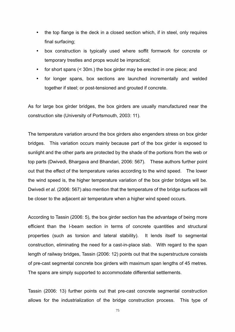
75
the top flange is the deck in a closed section which, if in steel, only requires
final surfacing;
box construction is typically used where soffit formwork for concrete or
temporary trestles and props would be impractical;
for short spans (< 30m.) the box girder may be erected in one piece; and
for longer spans, box sections are launched incrementally and welded
together if steel; or post-tensioned and grouted if concrete.
As for large box girder bridges, the box girders are usually manufactured near the
construction site (University of Portsmouth, 2003: 11).
The temperature variation around the box girders also engenders stress on box girder
bridges. This variation occurs mainly because part of the box girder is exposed to
sunlight and the other parts are protected by the shade of the portions from the web or
top parts (Dwivedi, Bhargava and Bhandari, 2006: 567). These authors further point
out that the effect of the temperature varies according to the wind speed. The lower
the wind speed is, the higher temperature variation of the box girder bridges will be.
Dwivedi et al. (2006: 567) also mention that the temperature of the bridge surfaces will
be closer to the adjacent air temperature when a higher wind speed occurs.
According to Tassin (2006: 5), the box girder section has the advantage of being more
efficient than the I-beam section in terms of concrete quantities and structural
properties (such as torsion and lateral stability). It lends itself to segmental
construction, eliminating the need for a cast-in-place slab. With regard to the span
length of railway bridges, Tassin (2006: 12) points out that the superstructure consists
of pre-cast segmental concrete box girders with maximum span lengths of 45 metres.
The spans are simply supported to accommodate differential settlements.
Tassin (2006: 13) further points out that pre-cast concrete segmental construction
allows for the industrialization of the bridge construction process. This type of

76
construction requires an important initial investment for setting up a casting yard and
purchasing special forms and erection equipment. This investment is justified for
large projects. However, it can also be economical for smaller bridges if existing
pre-casting yards could be used and the equipment could be standardized and reused
on several projects (Tassin, 2006: 13).
From the above analysis, the bridge girder for the conceptual ELRT model should be
pre-cast in the casting yard to make it more economical. The simple supported bridge
type helps to reduce the differential settlement and the girders can be erected with
special equipment which helps to make the construction procedure more convenient
and economical.
3.2.2.2.5 Design Challenges for Rail Bridges
According to Kohls and Urquhart (2007: 3), certain factors need to be considered
during the design procedure of rail structures. The differences between typical
highway bridges and rail bridges are not simply caused by the high live load which is
engendered by heavier train loadings. Loadings, service considerations and long
term maintenance need to be taken into consideration (Kohls & Urquhart, 2007: 3).
a) Loadings
According to Kohls and Urquhart (2007: 3), the following considerations should be
taken into account during the procedure of designing a rail bridge:
• Increased live load – the typical train loading is significantly larger than the
truck loads used in typical highway design.
• Derailment load – the design must consider the effects of a train derailing,
including the impact of such an occurrence.
• Rail/structure interaction forces – the rails are typically continuously connected

77
to the bridge deck, resulting in differential expansion and contraction effects
between the different materials.
• Longitudinal braking forces from trains – the braking force from the train is
typically a larger load than the longitudinal force used in the design of highway
bridges.
• Lateral rolling forces from trains – the effect of the train’s lateral moment is
carried through the rails into the bridge deck.
• Different critical section locations – the critical sections in a rail bridge under
train loading will be different from those typically anticipated under highway
loading.
Kohls and Urquhart (2007: 3) point out that the nature of the pre-cast segmental
construction bridge successfully solves these design issues. The concrete box
girder is torsionally rigid due to its closed trapezoidal shape (this was also proved by
the previous calculation in section 3.2.2.1.2). The torsional rigidity of the concrete
box girder makes it effective in resisting large torsion loads caused by derailment
loads from the train and other lateral forces. In addition, Kohls and Urquhart
emphasize that the design of railway bridges are facilitated by using the concrete
section to resist the loads. Hence, segmental reinforced concrete box girders are
suitable for use in the conceptual ELRT model.
b) Service Considerations
According to Kohls and Urquhart (2007: 3), the design criteria of serviceability for a
rail bridge are different from that of highway bridges. These differences include:
• Vibration and deflection criteria – the limitations established for vibrations and
deflections for rail structures are more stringent than typical highway loading
due to the sensitivity of the train operations to structure moment.
• Fatigue considerations – the bridge will be exposed to more significant cyclic

78
moments under train loadings, requiring greater attention to structural design
and details.
• Upward forces at piers – the location of the train on the bridge will result in
more frequent occurrences of upward forces at piers that must be addressed in
the superstructure to substructure connection.
• Noise control – the noise level created by trains is often a concern in areas
where the alignment passes through residential areas, commercial areas, or
parklands.
Kohls and Urquhart (2007: 3) point out that concrete is a natural dampener for both
noise and vibration. Hence, concrete girders can reduce noise and vibration such
that stringent criteria for rail structures can be satisfied. The closed box shape
ensures the rigidity of concrete segmental box girder and enhances the dampening.
These characteristics of segmental box girders can help to reduce vibration and
deflection in the structure, improving the serviceability of the bridge under train
loadings.
c) Long Term Maintenance
Kohls and Urquhart (2007: 5) state that future maintenance should be considered
when designing any structures. This maintenance will guarantee the functional
requirement of a structure throughout its anticipated design life. Kohls and Urquhart
(2007: 5) emphasize that long-term maintenance is important for a rail structures due
to the following:
• Difficulty of maintaining train traffic during maintenance – it is often difficult to
keep an active rail line open during significant maintenance because it is not
possible to direct the train along any other path than that set by the rails. With
a traffic bridge, as a comparison, it is possible to close lanes or route traffic
onto a shoulder during times of maintenance.

79
• Increased difficulty in replacement – a longer structure life must be considered
in the design to take into account the difficulty to replace a rail structure. To
build a replacement bridge, it is often not possible to reroute the rail to a
parallel structure, so the new bridge must be built on the existing footprint,
causing disruption to the active rail line.
Kohls and Urquhart (2007: 6) conclude that pre-cast segmental bridges are the types
of structures that have high durability for the following reasons:
Firstly, the pre-casting of the structural elements constructed in the casting
factory allows a controlled casting procedure. The quality controls for
factory-constructed girders are better than that of on-site casting.
Secondly, the post-tensioned superstructure affects the segmental box girders
in both the transverse and longitudinal directions and enables the bridge deck
to be in compression at all times. This pre-stressing force eliminates possible
cracks on the bridge deck, which in turn prevents the reinforced mild steel in
the box girder from being invaded by corrosive agents.
Thirdly, concrete itself is a highly durable material that does not need to be
coated or treated to prevent corrosion.
3.2.2.2.6 Two case studies about pre-cast concrete segmental box girder railway
structures
As mentioned previously, box girders have been widely used for bridge construction,
because of their internal merits. The discussion in section 3.2.2.2.5 showed how
pre-cast segmental construction works most efficiently under several environmental
and congested conditions. The following section presents projects with completed
bridges where pre-cast segmental construction was used. These projects
demonstrate the successful use of this kind of construction method under the
situations with similar challenges.
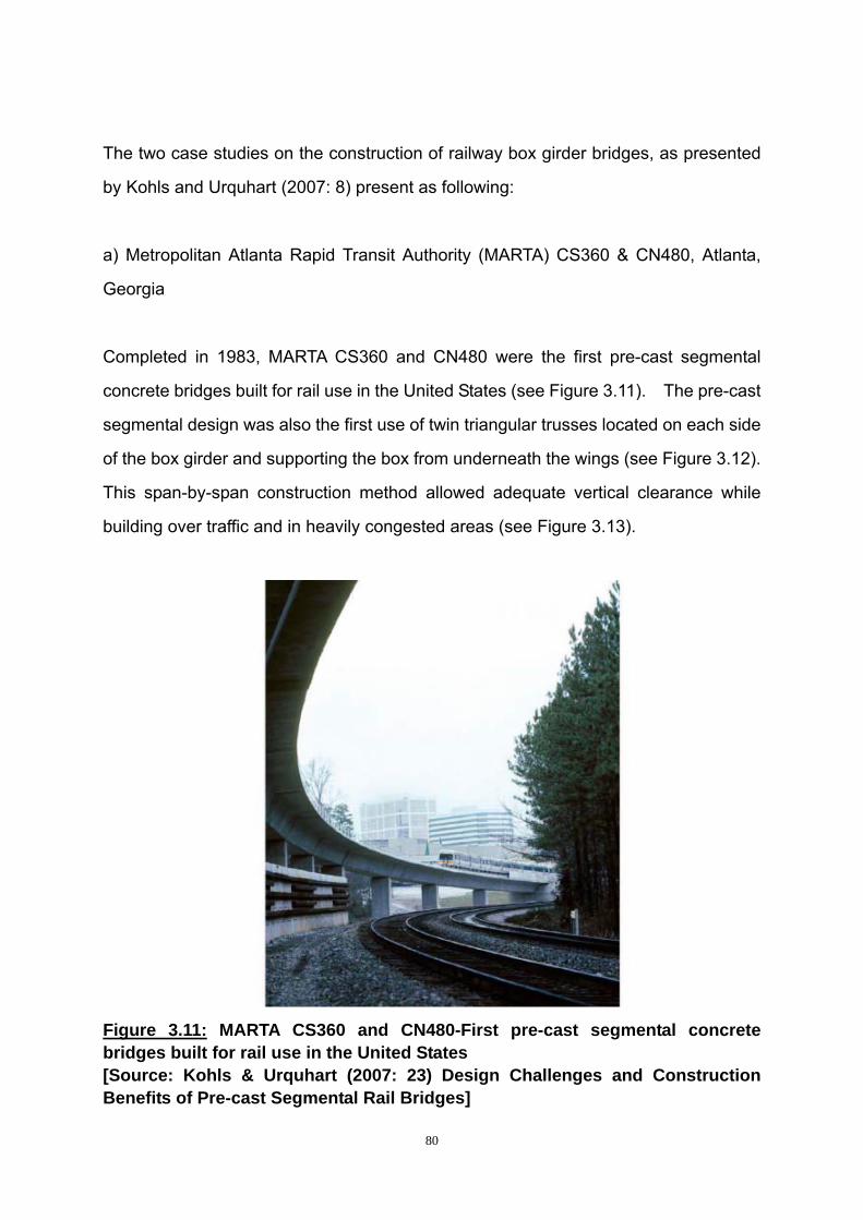
80
The two case studies on the construction of railway box girder bridges, as presented
by Kohls and Urquhart (2007: 8) present as following:
a) Metropolitan Atlanta Rapid Transit Authority (MARTA) CS360 & CN480, Atlanta,
Georgia
Completed in 1983, MARTA CS360 and CN480 were the first pre-cast segmental
concrete bridges built for rail use in the United States (see Figure 3.11). The pre-cast
segmental design was also the first use of twin triangular trusses located on each side
of the box girder and supporting the box from underneath the wings (see Figure 3.12).
This span-by-span construction method allowed adequate vertical clearance while
building over traffic and in heavily congested areas (see Figure 3.13).
Figure 3.11: MARTA CS360 and CN480-First pre-cast segmental concrete bridges built for rail use in the United States [Source: Kohls & Urquhart (2007: 23) Design Challenges and Construction Benefits of Pre-cast Segmental Rail Bridges]

81
Figure 3.12: MARTA CS360 and CN480-First use of twin triangular trusses for span-by-span construction. [Source: Kohls & Urquhart (2007: 24) Design Challenges and Construction Benefits of Pre-cast Segmental Rail Bridges]
Figure 3.13: Construction continued through congested Atlanta, minimizing disruption to existing traffic. [Source: Kohls & Urquhart (2007: 25) Design Challenges and Construction Benefits of Pre-cast Segmental Rail Bridges]

82
b) JFK Light Rail System, New York City, New York
This closed box girder shape creates a smooth underside for the structure, allowing
clean lines and an uncluttered appearance. The concrete mix was closely regulated,
using specific materials to generate the same concrete colour whether it was pre-cast
(superstructure), cast-in-place (substructure), or mixed on-site (closure pours). This
attention to detail resulted in an aesthetically pleasing structure for the airport and
surrounding area (see Figure 3.14).
Figure 3.14: JFK Light Rail System-Completed elevated track incorporated details to create an aesthetically pleasing structure. [Source: Kohls & Urquhart (2007: 32) Design Challenges and Construction Benefits of Pre-cast Segmental Rail Bridges]
3.2.3 ELRT sleepers and sleeper beds
In order to lay a high-quality railway track, three basic requisites that need to be
considered are economy, safety and comfort (Ponnuswamy, 2004: 149). Traditional

83
tracks are mainly composed of rail, sleeper and ballast. Rails are largely
standardised all around the world. Hence, the rail will not be discussed in great
detail in this research. The focus will be on the types of railway sleepers and
whether the track should be a ballasted or non-ballasted type.
According to Bonnett (2001: 67), the basic functions of sleepers and bearers or
timbers (for points and crossings) are needed to:
Spread wheel loads to ballast;
hold rails to gauge and inclination;
transmit lateral and longitudinal forces;
insulate rails electrically; and
provide a base for rail seats and fastenings.
Besides these basic functions that Bonnett describes, he further points out some
important secondary functions that also need to be considered. These include:
Supporting wheels and jacks direct (in a derailment situation);
acting as transverse beams when sitting on temporary ’way beams’;
supporting signal engineering and other safety related equipment (such as trip
cocks and point motors);
supporting conductor rails electrical bonds and feeder cables; and
reducing noise and vibration on non-ballasted bridge decks.
There are three main types of sleepers used worldwide according to the material used
for sleepers. Bonnett (2001: 67) mentions that timber sleepers, pre-stressed
concrete sleepers and steel sleepers are used. Traditionally, these sleepers are laid
on ballasted, which serves as the sleeper bed.
With the development of technology, the traditional ballasted type of track does not
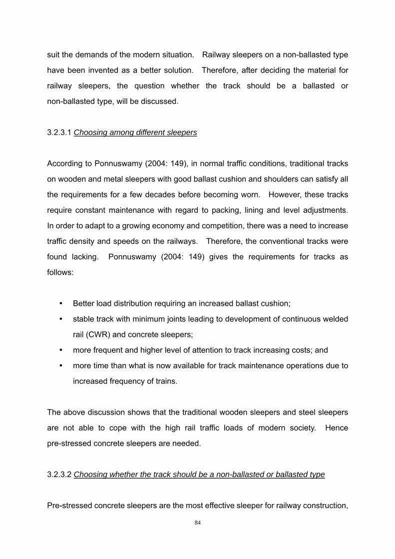
84
suit the demands of the modern situation. Railway sleepers on a non-ballasted type
have been invented as a better solution. Therefore, after deciding the material for
railway sleepers, the question whether the track should be a ballasted or
non-ballasted type, will be discussed.
3.2.3.1 Choosing among different sleepers
According to Ponnuswamy (2004: 149), in normal traffic conditions, traditional tracks
on wooden and metal sleepers with good ballast cushion and shoulders can satisfy all
the requirements for a few decades before becoming worn. However, these tracks
require constant maintenance with regard to packing, lining and level adjustments.
In order to adapt to a growing economy and competition, there was a need to increase
traffic density and speeds on the railways. Therefore, the conventional tracks were
found lacking. Ponnuswamy (2004: 149) gives the requirements for tracks as
follows:
Better load distribution requiring an increased ballast cushion;
stable track with minimum joints leading to development of continuous welded
rail (CWR) and concrete sleepers;
more frequent and higher level of attention to track increasing costs; and
more time than what is now available for track maintenance operations due to
increased frequency of trains.
The above discussion shows that the traditional wooden sleepers and steel sleepers
are not able to cope with the high rail traffic loads of modern society. Hence
pre-stressed concrete sleepers are needed.
3.2.3.2 Choosing whether the track should be a non-ballasted or ballasted type
Pre-stressed concrete sleepers are the most effective sleeper for railway construction,

85
therefore, they will be discussed in more detail. Whether the track should be a
ballasted or non-ballasted type plays a vital role with regard to the stability of railway
systems. The characteristics of the ballasted and non-ballasted type will be
discussed below.
3.2.3.2.1 Non-ballasted railway track versus ballasted railway track
According to Fumey (2002: 7), the function of ballast is to distribute load between
sleepers and support. Ballast has characteristics of stiffness and damping. It also
has characteristics of plasticity that have both advantages and disadvantages.
Fumey also presents the advantages and disadvantages of non-ballasted and
ballasted railway tracks:
The disadvantages of the plasticity of the ballasted track, which can be avoided by
using a non-ballasted track, are:
Middle term evolution of the geometry that needs periodic intervention
(frequency range from 0,5 to 6 years);
wear of the ballast by abrasion and fragmentation limiting the lifespan in the
order of 30 years (depending on traffic); and
limited lateral resistance imposing particular rules for CWR track.
However, on the other hand, Fumey points out that ballasted railway tracks have
certain advantages due to the plasticity of the ballast linked to the facility of use:
The tempo of track laying is more rapid than with non-ballasted track, with less
interruption and delay of traffic;
no difficulties to obtain the desired geometry of track with a process comprising
several phases of construction and the possibility to undertake as much local
retaking as necessary (to reduce cost);

86
simple adaptation to uncontrolled evolutions of the support: settlements in the
long term, differential settlements at railway bridge ends;
simple adaptation to modification of track alignment: change of characteristics
of switches and crossings, adaptation of transitions and cant for speed
upgrading; and
regeneration process well known and allowing circulation with restrictions.
Besides the above characteristics, Fumey (2002: 7) points out that the ballasted
railway track also has the following properties:
Disadvantages linked to projections of ballast and to imprints on rails;
advantages linked to the attenuation of sound propagation; and
contribution to the drainage of the track.
However, with a non-ballasted track a better control of the stiffness of the track is
achieved. This can reduce some problems such as rail corrugation.
Esveld (2003: 81) presents the great advantages of non-ballasted structures as
follows:
Reduction of structure height;
lower maintenance requirements and hence higher availability;
increased service life;
high lateral track resistance which allows future speed increases in
combination with tilting technology; and
no problems with churning of ballast particles at high-speed.
In order to handle the disadvantages of the ballasted track, the designs of
non-ballasted track can avoid all the obvious disadvantages that ballasted railway
tracks tend to have.

87
Fumey (2002: 8) points out that the economic statement specific to each project can
be modified by technical considerations, that is the differential settlement of
construction is less on railway bridges or tunnels than on earth works. As a
consequence of this characteristic, Fumey indicates that a non-ballasted track is more
favourable to choose for a project that has most of its layout in a tunnel or viaduct.
According to Esveld (2001: 231), the slow deterioration of ballast material, which is
caused mainly by traffic loading, is a general problem that occurs with a ballasted
track. Ballast is mainly composed of packed loose granular material. The
dispersion, wear, and break up of these grains can cause increasing geometrical
unevenness and clogging of the ballast bed by fine particles, which cause drainage
problems. Hence, regular maintenance is needed to restore the track alignment time
after time.
Fumey (2002: 7) further emphasizes that the plasticity of the ballasted tracks leads to
the need for periodic maintenance of the geometry to extend the design life of
ballasted track. A much shorter periodic maintenance cycle is needed for ballasted
track than that for a non-ballasted track. Hence the non-ballasted tracks are more
suited for use in railway systems in urban areas.
3.2.3.2.2 Basic criteria for choosing non-ballasted or ballasted railway track
In order to choose suitable forms of track for the conceptual model, certain aspects
need to be evaluated in order to determine which forms are suitable to use.
According to Bachmann (2003: 4) the following criteria affect the overall economical
evaluation:
Investment cost;
long term maintenance cost;

88
potential advantages of non-ballasted tracks through alignment smoothing to
natural field conditions: Shortening of construction periods;
cost influence of higher/lower availability;
relevance of comfort and riding quality criteria;
operational advantages by extended alignment parameters; and
relevance of airborne and structure borne noise.
Esveld (2003: 81) indicates that the basis of investment costs assessed for a new
project is mainly to consider the life cycle cost. Hence, the long-term maintenance is
an important factor to evaluate with regard to ultimate cost for a project. A quality
track with smooth alignment can greatly reduce the maintenance cost, increase
passenger comfort and relieve the impact between rail and trains. Little maintenance
is required and better operations can be executed. Noise is a vital factor in railway
systems, especially for an urban railway system. Hence, measures must be taken to
reduce noise levels.
Furthermore, Bachmann (2003: 4) gives the characteristic of non-ballasted railway
tracks as follows:
Low maintenance;
high availability;
increased service life;
reduced life cycle costs;
low structure height;
low weight;
high lateral track resistance which allows future speed increases in
combination with tilting technology; and
no problems with churning of ballast particles at high-speed.
The characteristics of non-ballasted railway tracks make non-ballasted railway tracks

89
extremely versatile. Esveld (2007: 1) emphasizes that the major advantage of
non-ballasted railway tracks is low maintenance and high availability. Esveld (2003:
81) further confirms that the ballasted track concepts would loose attractiveness in the
future as slab track systems become more popular. The lower height and weight of
non-ballasted tracks compared with traditional ballasted tracks make non-ballasted
tracks especially suitable for use in bridge structures. Hence, the track on a
non-ballasted type of track is much more suited for use in the conceptual ELRT
model.
3.2.3.3 Introduction of non-ballasted tracks for urban rail systems
Esveld (2003: 81) states that the concept of a non-ballasted railway track provides
good opportunities for the design of railway lines. This is especially significant if one
considers the life cycle costs, construction times, availability and durability of
materials that play an increasingly important role in railway design.
3.2.3.3.1 Main types of non-ballasted railway track
Ponnuswamy (2004: 149) points out that a certain number of forms of slab track was
introduced in railway systems in Europe and the United Kingdom (UK) in the 1960s.
The purpose of these was aimed at developing high-speed lines and reducing
maintenance problems elsewhere. The emphasis of their studies was on the
transmission of vibrations to the surrounding ground and the reduction of noise levels
caused inside and outside the trains. Ponnuswamy (2004: 150) mentions that a
study in 1976 indicated the prevalence of the following types of non-ballasted track on
different urban rail systems:
Laying concrete sleepers or blocks over a base or deck slab and subsequently
stabilizing by pouring grout or concrete around them (Budapest and
Sonneville).

90
Laying tracks complete with fasteners and dowels on auxiliary sleepers
supported by special props and subsequently pouring longitudinal beams
below (Cologne, Germany).
Laying a continuous reinforced cement concrete (RCC) floor on tunnel floor or
over formation, laying rails with rubber pads and elastic fastenings in position
and fixing to concrete slab with proper holding down/anchoring (Japan and
UK).
Laying the concrete slab to proper tolerances and then fixing the rail with base
plates and rubber pads on the same with proper holding down arrangements
(Netherlands).
The above-mentioned studies on the forms of non-ballasted railway track were done
in 1976 in order to develop railway tracks to adapt to modern circumstances.
Ponnuswamy (2004: 154) points out that there are three main types of non-ballasted
railway track in use nowadays in different parts of the world. These three types of
non-ballasted railway track are listed with a few examples of locations as follows:
a) Fixed Base
Continuous RCC Plinth: BART (San Francisco); Hong Kong Metro
Continuous Slab: UK and Europe; Kolkata Metro
b) Floating Slab with
Continuous Resilient Medium: Japan-Shinkansen lines; Germany-Berlin Metro
Resilient Pads at Intervals: Atlanta Metro; Honk Kong Airport line
c) Sleepers/Sleeper Blocks Inset in Concrete
Timber: Trials at Calcutta; BART- at turnouts and locations where lateral shifts

91
are expected
Twin Block Sleepers with Boot - (Sonneville, Stedef): Channel Tunnel, Europe,
Hong Kong Metro and BART at sensitive locations.
Having noted that three main non-ballasted railway tracks are used worldwide,
Ponnuswamy (2004: 158) provides the characteristics of different types of
non-ballasted railway track shown in table 3.4 as follows:

92
Table 3.4: Attributes of Different Types of non-ballasted railway Track
No Attributes Type Ⅰ: Continuous Slab or Plinth with DFF
Type Ⅱ: Floating Slab with continuous or isolated medium
Type Ⅲ: Sleepers or Blocks Insert in concrete or grout
Construction:
Accuracy and quality Good to fair — depends on skill and supervision
Very good. Needs little skill to achieve quality
Excellent. Medium skill required for achieving quality
Rate of progress Low 250 m/month/ party
Excellent 4 km-5 km/ month/ party
Low 250 m/month/ party
Ease of construction Good Difficult. Needs heavy equipment to handle
Medium
Cost Low ($ 1.5 million/km)
Highest ($ 3.2 million/ km)
High. ($ 2.0 million/km)
1.
Design Simple Needs high technology
Needs high technology
2. Dampening Fair to good depending on pads
Excellent Excellent
3. Noise Poor to good depending on pads.
Excellent — low Excellent — low
4. Vibration –Ditto– Excellent — low Excellent
5. Maintenance and replacement of pads/fittings
Good (easy) Difficult to replace units and maintain elastic medium
Easy. Replacement of boot/pad below sleeper difficult
6. Lightness of structure
Slab – heavy Plinth – lighter
Heaviest Medium
7. Proprietary nature Most self-reliant Needs import of technology
Needs import of technology
8. Other characteristics Economical and quicker for implementation
Most expensive
Expensive but preferable. Will take time to develop design and test
Note : 1. Pre-cast slab tracks used in Japan and on the S-Bahn in Berlin can be classified under this; 2. The cast-in situ block type used with bearing plates in BART and Washington Metro are variations of this process; 3. The new Netherlands Railway development of the Edilon type with rail embedded in Corkelast packing can come under this.

93
Table 3.4 shows the evaluations of these three types of railway track under the
different factors: design procedure, construction procedure and maintenance
procedure. For a simple comparison, these three types of railway track are divided
as follows: Type Ⅰ presents a continuous slab or plinth with direct fixation fastener
(DFF), Type Ⅱ presents a floating slab with continuous or isolated medium and Type
Ⅲ presents sleepers or blocks that are insert in concrete or grout.
Among all these factors, accuracy and quality, cost, noise, vibration, maintenance and
lightness of structure are of vital importance for a good railway track in urban areas.
With regard to accuracy and quality part, Type Ⅲ has a high level of accuracy and
quality while Type is only Ⅰ rated as “good”. Type is Ⅱ rated “very good”, which is
in-between the other two types. Little skill is needed to achieve the quality as found
at Type Ⅱ. Type needs Ⅲ a medium level of skill to achieve quality. However, the
skill and supervision determine the level of quality for each type. Accuracy and
quality can make the railway track even and stable, which is necessary for high speed
railways to be competitive. Among these three types of non-ballasted railway track,
Type Ⅲ has excellent accuracy and quality, which makes it suitable for the conceptual
ELRT model.
Type is Ⅰ the lease expensive among these types of railway non-ballasted railway
track having a cost of $ 1.5 million per kilometre. Type is the Ⅱ most expensive of
the three types with a cost of $ 3.2 million per kilometre. The cost of Type is in the Ⅲ
middle range, costing $ 2.0 million per kilometre. However, these costs are only an
estimate for non-ballasted railway tracks because material costs and labour costs are
not the same in all countries and regions. The cost for a system should take into
consideration into the long-term sustainability. Long-term sustainability should be
taken into consideration when the cost of a system is determined.
Both Type and Ⅱ Type are excellent Ⅲ with regard to low noise generation. Type Ⅰ

94
is rated “poor to good” with regard to noise emission and is dependent on the pads
that it runs on. Care for the environment is a major issue in world affairs especially
as it impacts upon the lives of people. Noise levels for systems need to be carefully
evaluated, especially in urban areas. Hence, both Type andⅡ Type are suitable Ⅲ
for use in the conceptual ELRT model.
Both Type and Ⅱ Type are excellent Ⅲ with regard low vibration generation while
Type doⅠ es generate vibration. Vibration generated from the track has an adverse
effect on both the built environment and human experience. Low vibration
engenders few disturbances for the surrounding area. The conceptual ELRT model
is supposed to be located on a main line with many roads and structures nearby.
Hence, both Type and Ⅱ Type can be Ⅲ used for the conceptual ELRT model.
It is easy to maintain Type and Ⅰ Type Ⅲ while it is more difficult to maintain Type
on elastic mediⅡ um. However, to replace the bottom or pad below the sleeper is
difficult for Type and Ⅲ it is also difficult to replace the units for Type . Ⅱ As
discussed above, maintenance also has a direct impact on the cost of a system.
Low maintenance also means that the system is more reliable and can be in use for a
much longer period. Hence, both Type and Ⅰ Type can be Ⅲ used for the
conceptual ELRT model. However, for Type , the pad below Ⅲ the sleepers needs to
be considered.
Type Ⅱ has the heaviest structure and Type isⅢ of a medium weight. However,
Type Ⅰ is heavier for a slab, but lighter for a plinth. For bridge structures, the lighter
the tracks, the fewer the pressures on the bridge foundations and bridge girders.
Hence, Type with Ⅰ a plinth could be chosen. However, Type should also Ⅲ be
taken into consideration for use in the conceptual ELRT model.
From the above analysis, sleepers or blocks Inserted in concrete or grout is possibly
the best among the three types of non-ballasted railway track.

95
3.2.3.3.2 Recent developments in slab track
Esveld (2003: 81) points out that the growth of traffic intensity has made the
maintenance and renewal work of railway tracks more difficult than before. For
instance, the interval for maintenance is less than 5 hours in the Netherlands. For
the Korean line (435 km from Seoul to Pusan), the interval for maintenance is no more
than 1.5 hours per night. Hence, low maintenance tracks are needed for modern
railway track systems.
Due to the natural advantages of the non-ballasted railway track, the technology of
non-ballasted railway track has developed rapidly in some countries. The following
section will introduce some types of non-ballasted railway track systems that are
internationally renowned.
The first type is the reinforced pre-stressed concrete slab used in Japan. According
to Esveld (2003: 82), the development work on the Shinkansen network was started at
the end of 1950s. The first Shinkansen line opened in 1964 from Tokyo to Osaka.
In 2003, five lines were in service and the sixth was under construction. The
Shinkansen slab track as shown in figure 3.15 below is mainly composed of a
sub-layer, stopper and concrete slab. The sub-layer using cement for stabilizing,
cylindrical ‘stoppers’ between two pieces of slab track prevent lateral and longitudinal
moment. It includes reinforced pre-stressed concrete slabs measuring 4.93 m x 2.34
m x 0.19 m (4.95 m x 2.34 m x 0.16 m in tunnels) and asphalt cement mortar, injected
under and between the slabs. This type of slab track provides a stable foundation for
the trains. However, the reinforced pre-stressed concrete slabs are too heavy for
use in bridge structures, because the slabs generate too much load for the bridge
foundations, which will in turn affect the long-term usage for railway bridge systems.
Hence, the reinforced pre-stressed slab track cannot be used for the conceptual ELRT
model.

96
Figure 3.15: The Shinkansen slab track
[Source: Esveld, C. (2003: 81). Recent developments in slab track.]
The second type of non-ballasted track is the Rheda 2000 system in Germany.
Esveld (2003: 82) states that non-ballasted railway tracks developed quickly in
Germany. The German Railway opened seven new types of non-ballasted railway
lines for tests in Karlsruhe in 1996. Among all these systems the most developed is
Rheda 2000. The Rheda system achieved configuration through a significant
simplification by eliminating the conventional concrete trough. As shown in figure
3.16 below, a considerable reduction in the structural height was achieved, because
the trough was eliminated and twin-block sleepers were used. Mathur and Negi
(2005: 7) emphasize the essential advantages of Rheda 2000 systems as follows:
Great precision of gauge and track geometry due to the cross sleepers used;
no need to use compensation tolerances in rail fastenings, otherwise
necessary to compensate for track positioning errors during installation;
no periodic occurrence of waves in the rails;
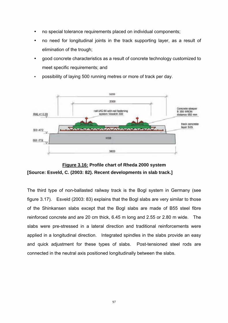
97
no special tolerance requirements placed on individual components;
no need for longitudinal joints in the track supporting layer, as a result of
elimination of the trough;
good concrete characteristics as a result of concrete technology customized to
meet specific requirements; and
possibility of laying 500 running metres or more of track per day.
Figure 3.16: Profile chart of Rheda 2000 system
[Source: Esveld, C. (2003: 82). Recent developments in slab track.]
The third type of non-ballasted railway track is the Bogl system in Germany (see
figure 3.17). Esveld (2003: 83) explains that the Bogl slabs are very similar to those
of the Shinkansen slabs except that the Bogl slabs are made of B55 steel fibre
reinforced concrete and are 20 cm thick, 6.45 m long and 2.55 or 2.80 m wide. The
slabs were pre-stressed in a lateral direction and traditional reinforcements were
applied in a longitudinal direction. Integrated spindles in the slabs provide an easy
and quick adjustment for these types of slabs. Post-tensioned steel rods are
connected in the neutral axis positioned longitudinally between the slabs.
98
Figure 3.17: Bogl system
[Source: Esveld, C. (2003: 82). Recent developments in slab track.]
The fourth type of non-ballasted railway track is a special track in the Netherlands.
Esveld (2003: 83) states that this high-speed line is located in the south of the
Netherlands. The track uses a piled concrete slab of a low viaduct and a separate
Rheda 2000 track slab. At 35 m intervals, both the supporting structure and the
Rheda slab are enlarged to restrict longitudinal forces in the concrete and
displacements at the end of the structure. The vertical relative displacements were
confined to 2 mm between the substructure elements at the expansion joints.
The fifth type of non-ballasted railway track is the Edilon block track system that is
specially used for bridges and tunnels as shown in figure3.18 below. Esveld (2003:
84) explains that in order to construct this type of system, the first step is to place the
rails and blocks in position. Then the blocks are cast using Corkelast (a cork /
polyurethane mixture) which can provide enough elastic support. This type of
non-ballasted railway system has already been used by Prorail for 100 km and on
light rail systems in the Netherlands and in the Madrid Metro for approximately 100
km.

99
Figure 3.18: Edilon block track
[Source: Esveld, C. (2003: 82). Recent developments in slab track.]
Besides the non-ballasted railway systems mentioned above, another type of
non-ballasted railway track system, called embedded rail structures, will be introduced
below.
Esveld (2003: 84) states that a continuously supported rail system has been in use in
the Netherlands on a small scale since 1976. The system is known as the
Embedded Rail Structure (ERS). ERS uses a compound consisting of Corkelast to
provide continuous support for the rail. Esveld points out that one of the big
advantages of ERS is that the track is built ‘top-down’, so the tolerance in the
supporting structure has no effect on the track geometry. Another major advantage
of ERS is that the wheels are not subjected to any difference in vertical stiffness as on
a track with sleepers. The stiffness difference is one of the major causes of
corrugation. Twenty years of experience by Prorail has proved that ERS requires
little maintenance (Esveld, 2003: 84).

100
Besides the normal ERS, Esveld (2003: 84) indicates that a new track system named
Embedded Rail in Asphalt (ERIA) was developed in the Netherlands with an asphalt
pavement. The ERIA is a special solution for trams and light rail trains in urban areas
because it is silent.
3.2.3.3.3 Analysis of the popular non-ballasted railway tracks
Among all these types of non-ballasted railway track systems, the Shinkansen
reinforced pre-stressed concrete slab and Bogl systems are too heavy to be used on
bridge structures. Heavy loads on the bridge will cause too much pressure on the
bridge foundations. While the trains pass through, the vibration will engender more
moments to the bridge deck and bridge pillar. Heavy self-weight of the bridges and
railway tracks together with the high imposed loads from trains, will cause more
moments. In order to avoid the heavy loads, the track systems on bridges should be
as light as possible for long-term considerations. Therefore, these two types of
non-ballasted railway track systems will not be considered for the conceptual ELRT
model.
The Rheda 2000 system, the special track in the Netherlands and the Edilon block
track system seem reasonable for bridge structures. The Rheda 2000 system
reduces the height significantly, which in turn reduces the weight of the track greatly.
In order to reduce the railway track height, twin-block sleepers are the most suitable.
The special track in the Netherlands uses piled concrete slabs to provide the stability
for the railway track. However, the differential settlement of the railway tracks on
piled concrete slabs is not as low as that on piled foundation bridges. Through using
piled concrete slabs, little maintenance is required and it can support the high speed
of trains. The Edilon block track system, which uses block sleepers, is a special
solution for bridges and tunnels.

101
The ERS tracks are special types that do not need sleepers at all. The rails are
directly embedded into the railway slab. The new ERIS system can be used for light
rail systems in urban areas.
The non-ballasted railway tracks discussed above seem to be suitable for use in an
ELRT system. However, they all need the concrete slabs to provide a stable route
for the railway track. For railway tracks on bridges this is not necessary, because the
allowable settlement on a bridge is much smaller than that of a railway track at ground
level. The special track in the Netherlands used piled concrete slabs just like the
railway on a bridge.
Seeing that the allowable settlement in bridges is much smaller than that of railway
track at ground level, the conceptual ELRT model will provide a much more stable
railway track than the piled concrete slab. Low maintenance of non-ballasted railway
tracks makes the non-ballasted railway track most suitable for the conceptual ELRT
model. Like the Rheda 2000 system, twin-block sleepers are more beneficial than
others. Hence, twin-block sleepers are regarded as the most suitable railway
sleepers for the conceptual ELRT model.
3.2.3.3.4 Twin-block sleepers
According to Bonnett (2001: 71), the twin-block sleeper consists of two reinforced
concrete blocks and a steel tie bar. The two blocks are connected together with a
steel tie bar cast into the blocks. In Europe, particularly in France, this type of
sleeper is widely used except in the UK. The standard weight of twin-block sleeper is
230 kg which is less than the equivalent mono-block. However, Bonnett explains
that the handling and placing of twin-block sleepers is difficult, because twin-block
sleepers tend to twist when lifted. Besides the relatively low weight compared to
other reinforced concrete sleepers, twin-block sleepers can also be incorporated into
a non-ballasted slab track or monolithically embedded into road surfaces for light rail

102
street running by providing resilient ‘boot’.
According to Züblin Technology (2007: 2), the reinforcing bars between reinforced
concrete sleeper heads do not only provide the accuracy of geometry during
installation, but also add additional anchorage in the concrete. Hence, a twin-block
sleeper provides a stable support to trains.
3.2.3.3.5 Installation of twin block sleepers
According to Esveld (2001: 241), a new installation concept was developed for the
Rheda 2000 system with the purpose of reducing the expensive construction costs.
By omitting the concrete trough, it was possible to remove a complete step in the work
sequence. The application of the light twin-block sleepers significantly simplified the
installation procedure at the construction site and enabled the mechanized installation
of prefabricated track panels at the same time. The developed surveying techniques
especially enhanced the cost effectiveness of the track installation process. Mathur
and Negi (2005: 7) claim that this new technique was developed through a portal and
spreader-bar adjustment together with a spindle base adjustment, which enables the
exact alignment and fixing of the track system, even under the most unfavourable
installing conditions.
Esveld (2001: 241) mentions that during the earthworks, the installation of the Rheda
2000 begins with the placement of a concrete roadbed using a slipform paver.
Furthermore, Mathur and Negi (2005: 6) point out that a hydraulically bonded support
layer (HSL) is necessary while installing the track-supporting layer. According to
German highway standards, the thickness of this layer is 300 cm.
The conventional track installation process can also be applied to the twin-block
sleeper. The concrete base-sockets make it easy for loaded construction vehicles to
use the rails before the foundation are accurately positioned and secured in place.

103
Hence, to lay the track in a single sleeper mode, or in the form of assembled track
panels, is possible (Esveld, 2001: 241).
Esveld (2001: 241) indicates that the arrangement of the slab layer reinforcement
within the sleeper lattice-truss makes it possible for the installation of the
reinforcement to take place with the track being laid at the exact same time. Based
on this procedure, the construction crew places the required reinforcing rods on the
concrete roadbed and inserts these reinforcing rods through the lattice-girder
compartment as shown in figure 3.19 below.
Figure 3.19: Twin-block sleepers
[Source: Esveld, C. (2001: 241). Modern Railway Track.]
3.2.3.4 Noise and vibration problems of non-ballasted railway tracks for urban rail
systems
According to Ludvigh (2004:6), more noise will be produced by non-ballasted railway
tracks than by ballasted railway tracks, because the slabs cause the rolling noise to
reverberate. Under these circumstances, elastic pads with low stiffness provide a
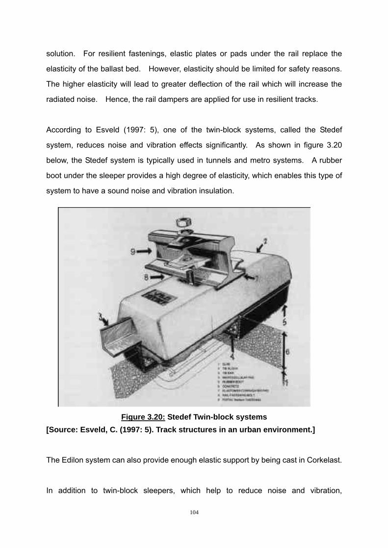
104
solution. For resilient fastenings, elastic plates or pads under the rail replace the
elasticity of the ballast bed. However, elasticity should be limited for safety reasons.
The higher elasticity will lead to greater deflection of the rail which will increase the
radiated noise. Hence, the rail dampers are applied for use in resilient tracks.
According to Esveld (1997: 5), one of the twin-block systems, called the Stedef
system, reduces noise and vibration effects significantly. As shown in figure 3.20
below, the Stedef system is typically used in tunnels and metro systems. A rubber
boot under the sleeper provides a high degree of elasticity, which enables this type of
system to have a sound noise and vibration insulation.
Figure 3.20: Stedef Twin-block systems
[Source: Esveld, C. (1997: 5). Track structures in an urban environment.]
The Edilon system can also provide enough elastic support by being cast in Corkelast.
In addition to twin-block sleepers, which help to reduce noise and vibration,

105
embedded tracks can also have the same function. As mentioned, the ERIA system
in the Netherlands has a characteristic of being silent and is especially suitable for
trams and light rail transit in urban areas.
3.2.3.5 Proposed railway track systems for the conceptual ELRT model
The foregoing section introduces some of the types of popular modern railway tracks
and sleepers. New innovations of tracks and sleepers have made them more
adaptable to the current need by eliminating traditional deficiencies. Each type of
track or sleeper has its own special usage. In order to choose a proper type of
railway track, Esveld (2001: 14) indicates the following requirements that need to be
taken into account:
The track must be constructed in such a way that the trains running on it do not
cause excessive environmental pollution in the form of noise and ground
vibrations.
Costs of the total service life of the track must be as low as possible.
Maintenance should be low and as inexpensive as possible.
Based on the requirements that Esveld indicates and the characteristics of tracks that
were discussed above, the track on a non-ballasted type is best suited for use in the
conceptual ELRT model.
As for the sleeper, twin-block sleepers are best suited to the conceptual ELRT model
for the reasons indicated below:
Firstly, a twin-block sleeper with rubber boot enables this type of sleeper to
have a good noise and vibration insulation. This meets the first consideration
that Esveld mentioned. On this aspect, twin-block sleepers and embedded
tracks do not differ much.
106
Secondly, the costs of the total service life including initial costs, and
maintenance costs, are much less for twin-block sleepers when compared with
the embedded tracks, because twin-block sleepers use much less material
than embedded tracks, in which the reinforced concrete slabs are placed.
For construction, the concrete slabs of embedded tracks need slipform pavers,
which are also costly. However, twin-block sleeper can be pre-cast in the
factory and transported to the site for adjustment, which is more cost effective.
As for the maintenance, embedded tracks need little maintenance. The
maintenance for twin-block sleepers is also easy, as was indicated by
Ponnuswamy (2004: 158).
Thirdly, the maintenance of bridges also needs to be taken into account when
considering the maintenance for an elevated railway track. The weight of
embedded tracks is much than that of twin-block sleepers. Hence, the
twin-block sleepers add fewer loads to bridge decks, pillars and bridge
foundations, which can greatly reduce the maintenance cost and the stability
of the whole system.
The railway tracks for the conceptual ELRT model are all elevated, therefore this
makes it possible to simplify the whole system through reserving space for twin-block
sleepers. This means that the upper part of the bridge deck may be designed thicker
and secured with plates that are connected with twin-block sleepers. This will help to
control the gauge and integrated the bridge deck and twin-block sleepers together by
anchoring them. Furthermore, later installation allows for the adjustment of the track
geometry. If the twin-block sleepers are prefabricated directly on box girders, the
track geometry tends to be uneven because there may be some errors, which are
caused by the deviation of the installation of the bridge decks. For the above
reasons, twin-block sleepers on a non-ballasted sleeper bed are most suitable for use
in the conceptual ELRT model.
107
3.3 Summary and conclusions
Chapter 2 concluded that the conceptual ELRT model could provide a better solution
for the development of an effective transportation system. The main civil engineering
components for the conceptual ELRT model were analysed in this chapter. The four
main components that play an important role in the conceptual ELRT model are the
ELRT foundation, the ELRT girder the ELRT sleeper and sleeper bed. For each
component, there are certain forms that can be used under different circumstances.
Piled foundations provide low allowable settlement for bridges. Through in-depth
analysis of piled foundations, bored and cast-in-place piles are the most suitable for
the conceptual ELRT model.
Box girders have much more stiffness than T section and I section girders, both in
bending and in torsion. By comparing various forms of box girders, the trapezoidal
segmental box girder is the most suitable for the conceptual ELRT model.
Non-ballasted tracks require less maintenance than that of a ballasted track. The
less maintenance of the non-ballasted track makes it more economical. In addition,
less maintenance of the non-ballasted track makes it easier to operate and control.
By comparison, twin-block sleepers on a non-ballast sleeper bed are most suitable for
the conceptual ELRT model.

108
CHAPTER 4
RESEARCH METHODOLOGY
4.1 Introduction
The preceding chapters presented the background of this research and defined the
main civil engineering components for the conceptual ELRT model. Through the
analysis of bridge foundations, bridge girders, railway sleepers and whether the track
should be a ballasted or non-ballasted type, the most suitable civil engineering
components were determined for the conceptual ELRT model.
In this chapter, the methods used for the collection of primary and secondary data for
this research, are described. The dataset that was used to validate and verify the
most suitable civil engineering components is also described in this chapter.
4.2 Research methodology
According to Leedy (2005: 93), data are related with methodology. Hence, the
nature of the data and the research problems determine the research methodology to
be used.
4.2.1 Qualitative versus quantitative research methodology
In general, two main approaches are used for research and these are described as
follows:
The purpose of the quantitative approach is to develop generalizations through
establishing, confirming or validating relationships that can contribute to theory

109
(Leedy, 2005: 95).
Qualitative researchers, usually in an exploratory nature, seek a better
understanding of complex situations (Leedy, 2005: 95). However, Leedy
(2005: 133) gave two characteristics that qualitative approaches have in
common. The first is that they focus on the naturally occurring phenomena,
which means that these phenomena happen in the real world. The second is
that qualitative studies usually study those phenomena in depth which involves
each aspect of those phenomena.
After examining the characteristics of each methodology as viewed above, it was
determined that a qualitative research approach was more suitable for this research,
because the study is exploratory and aims at determining the most suitable civil
engineering components for a conceptual ELRT model.
4.2.2 The specific qualitative approach for this research: grounded theory
approach
The main purpose of this research was to determine the main civil engineering
components for a conceptual ELRT model. Leedy (2005: 140) explains that the main
purpose of a grounded theory approach is to develop a theory which begins with the
data collection. By analysis and categorisation of the data, the theory is developed.
More specifically, a grounded theory approach develops a theoretical model by
analyzing the data with a prescribed set of procedures.
Furthermore, Tan (2004: 48) states that the grounded theory approach is sometimes
used to delineate the building of a hypothesis from specific instances, which is by
using an inductive approach. According to Fellows and Liu (2003: 103), the main
characteristic of the grounded theory approach is directed at theory-building rather
than theory-testing. Hence, case studies are also used for the grounded theory
approach. Case studies of some selected successful LRT projects will help to
110
optimise the conceptual ELRT model. Due to the exploratory nature of this research,
the emphasis will be on exploring the most suitable civil engineering components for a
conceptual ELRT model, rather than confirming any previously proven views.
Through the grounded theory approach, the main civil engineering components that
are the most suitable for the conceptual ELRT model will be developed, validated and
verified. Therefore, grounded theory is the most suitable methodological approach
for this research.
4.2.3 Data collection methods
According to Leedy (2005: 140), a grounded theory approach typically focuses on a
process related to a particular topic and develops a theory or model as the ultimate
goal about that process. Leedy (2005: 144) points out that the data collection for a
grounded theory study includes interviews and the other relevant data sources. In
order to determine the main civil engineering components for a conceptual ELRT
model, the following datasets had to be collected:
4.2.3.1 Dataset 1: Previous studies about LRT in NMB
This dataset should include an analysis of the feasibility studies that have been done
for the NMB area from 1984 to 1989. These documents had to be collected from
NMBM.
4.2.3.2 Dataset 2: Previous case studies on LRT systems
This dataset was needed so as to obtain some information about LRT systems.
South Africa has not had any LRT projects before; therefore it was impossible to get
LRT experiences from successful projects of LRT in South Africa. Hence, most of
these case studies were done on LRT systems from abroad. Their data was
111
collected from books and the Internet.
4.2.3.3 Dataset 3: Guidelines from literature for the most suitable civil engineering
components for a conceptual ELRT model
The first two datasets gathered information from the previous studies about LRT
systems. In order to avoid the adverse effect of previous LRT system, a conceptual
ELRT model was proposed. The related technologies for each component for the
conceptual ELRT model had to be taken into considerations. In order to keep up with
the development of modern technology and the need for the current transport
situation, each component of the conceptual ELRT model had to be analysed in depth.
The civil engineering fields identified in this dataset included the discipline of railway
engineering, bridge engineering and foundation engineering. These technologies
were obtained from books, journals and works from research institutes through the
library and the Internet.
4.2.3.4 Dataset 4: Questionnaire surveys among engineers, experts and scholars
In this dataset, questionnaire surveys related to the most suitable civil engineering
components of the conceptual ELRT model will be done. Various forms of each
component will be listed in the questionnaires based on Dataset 3. After the
questionnaires will be developed, they will be sent to experts, scholars and engineers
in related fields. The opinions from the engineers, experts or scholars will be
included as Dataset 4 in order to evaluate the most suitable civil engineering
components of the conceptual ELRT model. Electronic mailing (e-mail) will greatly
simplify the process of sending out the questionnaires. The e-mail addresses of the
engineers, experts and scholars were found using the following methods:
Firstly, the contact information was obtained from articles in the related fields that they
had published. These articles were found using a search engine of the NMMU;

112
Secondly, contact information was obtained from professional associations in related
engineering fields. Through such contacts, contact information was obtained.
4.2.3.5 Dataset 5: Review of the conceptual ELRT model by civil engineering experts
The conceptual ELRT model should be verified by experts to determine the most
suitable civil engineering components for the conceptual ELRT model.
The nature of this research topic meant that many experts in the railway engineering,
bridge engineering and foundation engineering fields were located all over the world,
which made it impossible to conduct face-to-face interviews. E-mail based reviews
were the solution to this problem. E-mails are popular nowadays because of their
global reach, fast response and cost efficiency (Tan, 2004: 132).
Using e-mails also allows respondents more time to think about the questions before
responding. However, Tan (2004: 132) points out that one of the disadvantages of
using e-mail surveys was that there were often incomplete replies or poor responses.
The other possible negative aspect of this method is that the respondents may not
own a computer or have access to the Internet. However, this problem does not
exist in this research because the respondents were all from the civil engineering
fields and all have access to the Internet.
4.2.4 Data analysis
After these datasets were collected and analysed separately. The analysis of each
dataset is presented below.

113
4.2.4.1 Dataset 1: Previous feasibility study in NMB
After obtaining the documents about the feasibility study for the NMB area from 1984
to 1989, these documents were analysed. The conclusion of the NMB LRT feasibility
study, which showed that the LRT was the most suitable primary mode of transport to
serve the NMB area at the time of study, was introduced in Chapter 2.
4.2.4.2 Dataset 2: Analysis of case studies
Some successful case studies of LRT systems from America and Canady were
analyzed from the planning stage to the implementation stage as shown in Chapter 2.
By comparing the advantages and disadvantages of each successful project, the
advantages of the LRT system became more obvious. At the same time, more
emphasis was placed on the problems of these successful LRT systems. After that,
the Bangkok ELRT system is introduced. The civil engineering components for the
Bangkok ELRT system provided a reference to determine the most suitable civil
engineering components for the conceptual ELRT model.
4.2.4.3 Dataset 3: Analyses of suitable civil engineering components for the
conceptual ELRT model
In order to determine the most suitable civil engineering components for the
conceptual ELRT model, the available literature was analysed in depth and presented
in Chapter 3. Various possibilities consist for each component, and can be applied in
a specific set of circumstances, therefore each component had to be analysed in
depth.
The characteristics of various foundations were described in Chapter 3 (foundation
part). By comparing the advantages and disadvantages of various types of
foundations, it was found that piled foundations were the most suitable for railway

114
bridges. Various types of piled foundations were analysed to determine which type
was the most suitable piled foundation for the conceptual ELRT model.
Different shapes of bridge girders have different capacities to resist torsion and
bending. As calculated in Chapter 3 (girder part), the moment of inertia and torsional
resistance of a box girder is higher than that of a T-section and an I-section.
Therefore, the different forms of box girders were further analysed. By following the
whole production procedure from design to construction, the most suitable box girder
was selected for the conceptual ELRT model.
Railway track and sleeper technology has developed greatly in recent years. The
advantages and disadvantages of various railway sleepers, together with the sleeper
bed, were described in Chapter 3 (sleeper part). By comparing the various types of
railway tracks with railway sleepers from the construction period to the maintenance
period, the most suitable sleeper type and the sleeper bed was determined for the
conceptual ELRT model.
4.2.4.4 Dataset 4: Analysis of feedback on questionnaires
The questionnaires were drawn up and based on the content that was analysed in
Dataset 3. Various forms of components were listed in the questionnaires, for the
respondents to choose. After receiving the completed questionnaires from the
respondents, the results will be categorized according to the different civil engineering
components of the conceptual ELRT model and will then be sent to a statistical
agency for the statistical analysis. The results should include frequency tables and
descriptive statistics, which will greatly simplify this dataset, which will make it
possible to identify the most suitable civil engineering components for the conceptual
ELRT model – from experts’ and practitioners’ point of view.
After comparing the results of the questionnaire surveys, the importance of the criteria

115
for each component and the most suitable components must be identified. The
respondents must be experts, scholars and engineers of related fields. Especially
the experts in their fields with many years of experience and their opinions must be
used to verify the conceptual ELRT model contained in Dataset 3. The technologies
of foundation engineering, bridge engineering and railway engineering do not differ
much all around the world. Hence the opinions of the engineers, experts or scholars
from these fields represent the opinions of the civil engineering community.
The main civil engineering components used in the conceptual ELRT model cover the
discipline of foundation engineering, bridge engineering and railway engineering.
Some of the respondents must be experts in these fields. Therefore, the opinions of
the respondents must be limited to their particular discipline or disciplines. The
questionnaire survey results will be used to validate Dataset 3 and should prove the
reliability of the data on the components for the conceptual ELRT model.
4.2.4.5 Dataset 5: Analysis of the experts’ review of the civil engineering components
selected for the conceptual ELRT model
After the opinions were obtained from engineers, experts or scholars, the data was
categorized according to each civil engineering component. The analysis must take
into consideration the planning stage, usage, maintenance and further retrofit of the
main civil engineering components for the conceptual ELRT model. Then Dataset 5,
Dataset 4 and Dataset 3 must be compared and analysed to determine the most
suitable civil engineering components for the conceptual ELRT model.
4.2.5 Validity and reliability of data
Leedy (2005: 28) indicates that the validity of a measurement is the supposed extend
to measure the instrument measures. Grounded theory used in this research use
five datasets to validate and verify the data. The first three datasets present:

116
(i) the previous feasibility of LRT in NMB; (ii) successful LRT and ELRT systems
abroad; and (iii) various components of the conceptual ELRT model. (Revise to
explain 3 datasets). Through analysis of the characteristics of successful LRT
systems, an ELRT system, which will be more efficient for use in urban areas, will be
developed. The characteristics of various civil engineering components, which make
up a conceptual ELRT model, enabled the selection of the most suitable civil
engineering components. Because these technologies were obtained from books,
journals and works from research institutes through the library and the Internet, these
datasets are valid.
According to Leedy (2005: 29), reliability refers to the results of a measuring
instrument being consistent with the entity being measured. The methods of
questionnaires and experts reviews are used to validate dataset 3 and to prove the
validity of the data. The questionnaires will be sent to engineers, scholars and
experts who belong to the fields of foundation engineering, bridge engineering and
railway engineering. A total of 86 questionnaires will be sent to engineers, scholars
and experts in the related fields. Their responses will be validated by means of a
further expert review. After the questionnaires are collected and analyzed, the
experts’ reviews are needed to further validate and verify the main civil engineering
components for a conceptual ELRT model. Experts have more years of experience
in their related fields and their expertise is more reliable than those young engineers.
4.3 Summary and conclusions
This chapter contains the research methodology to be used for this research. The
qualitative research approach was explained as well the use grounded theory
approach. Furthermore, the datasets were described and the analysis procedure for
each dataset was explained.
Dataset 1 was drawn of the previous study about the LRT system in the NMB area,
117
which indicated that the LRT is the most suitable primary transport mode to be used in
the NMB area at that time. Dataset 2 presented was based on an analysis of some
case studies of LRT systems. Dataset 3 was drawn from a literature study,
theoretical calculation and previous practical experience. Dataset 4 deals with the
analysis of the questionnaire surveys. Dataset 5 will be obtained from experts for
final modification and verification of the most suitable civil engineering components for
the conceptual ELRT model.
Although some datasets will include some quantitative data, the emphasis in this
research is on the collection, analysis and interpretation of qualitative data, to
determine the most suitable civil engineering components for the conceptual ELRT
model.
118
CHAPTER 5
RESULTS OF THE EMPIRICAL INVESTIGATION
5.1 Introduction
Chapter 3 presented the most suitable civil engineering components for a conceptual
ELRT model based on the theoretical calculations and literature concerning previous
engineering projects and studies. As indicated in Chapter 4, questionnaires were
prepared to determine the most suitable civil engineering components for the
conceptual ELRT model and sent to engineers, experts and scholars. Out of the 86
questionnaires that were sent out, 27 of completed questionnaires were returned.
In this chapter, the responses of the respondents are reported and analysed with
regard to ELRT components. Through statistical methods, frequency results were
obtained, which helped to determine the importance of criteria and the suitability of
civil engineering components.
5.2 Most suitable civil engineering components for the conceptual ELRT model
Based on the main civil engineering components for the conceptual ELRT model, the
questionnaire survey about ELRT foundations, ELRT girders, railway sleepers and the
type of sleeper bed were sent to engineers, experts and scholars for their responses.
Out of the 27 respondents, 4 of them were from the USA, 22 were from China and 1
was from Australia.
The respondents were engaged in a number of fields. The respondents were
engaged as follows: Seven in the field of bridge design, two in the field of
prefabricated bridge girders, 17 in the field of railway and bridge construction and one

119
in the field of railways and structures. Besides one researcher, who was qualified
with a PhD and has worked for 5 years, all of the respondents had at least seven
years of working experience. Two experts had working experience of 28 years each.
The following section will indicate the components that these respondents considered
to be the most suited for the conceptual ELRT model. The results of the
questionnaire survey will begin with the respondents’ views on the ELRT foundation,
followed by the ELRT girder and then the sleepers and sleeper bed.
5.2.1 Suitable ELRT foundation for the conceptual ELRT model
The questions concerning the ELRT foundations were divided into two sections. The
first section dealt with the criteria that needed to be considered when designing ELRT
foundations and the other dealt with the suitable type of ELRT foundation to be
selected. The following sections will analyse the criteria and the suitable type of
ELRT foundation separately.
5.2.1.1 Criteria for ELRT foundations for the conceptual ELRT model
The importance of the criteria needed for ELRT foundations are described in table 5.1
as follows:

120
Table 5.1: The importance of criteria from civil engineers, experts and scholars
(5 = most important, 4=very important, 3= important, 2=not important, 1 = least
important)
Respondents’ choice (%) Code for
statistics Criteria
5 4 3 2 1
Total
number Mean
Stand
deviation
BF_A_1
High resistance
to imposed load
from railway
bridge
91.666 8.333 24 4.833 0.564
BF_A_2
High horizontal
bending
resistance
87.500 4.166 8.333 24 4.791 0.588
BF_A_3 High horizontal
load resistance 91.666 4.166 4.166 24 4.875 0.448
BF_A_4 Low allowable
settlement 87.500 8.333 4.166 24 4.833 0.481
BF_A_5
Minimum
disturbance of
the current
transportation
systems
87.500 4.166 4.166 4.166 24 4.750 0.737
BF_A_6
Little or no
ground heave to
the surrounding
structures
87.500 8.333 4.166 24 4.708 0.806
BF_A_7 High
constructability 91.666 8.333 24 4.916 0.282
BF_A_8
Minimum
occupation of
land / space
45.833 41.666 12.500 24 4.333 0.701
BF_A_9
Require minimal
information of
soil conditions
5.263 21.052 36.842 26.315 10.526 24 2.842 1.067
BF_A_1
0
Economical
design 70.833 25.000 4.166 24 4.666 0.564
BF_A_11 Economical
construction 75.000 20.833 4.166 24 4.708 0.550
Criterion 1: The foundation should have high resistance to imposed load from
railway bridges - As shown in table 5.1, out of the 24 respondents who answered this

121
question; approximately 92 percent of them regarded this criterion as most important.
Chapter 3, section 3.2.1.2 also indicated that bridge foundations should resist the high
imposed loads that account for two-thirds of the dead load. This is much higher than
that of roadway bridges and other building foundations.
Criterion 2: The foundation should have high horizontal bending resistance -
Approximately 88 percent of the 24 respondents considered this criterion most
important. This is due to the fact that the eccentric load caused by the trains and
winds, impacts on the ELRT foundation, which therefore requires a high resistance to
horizontal bending.
Criterion 3: The foundation should have high horizontal load resistance -
Approximately 92 percent of the respondents felt that this criterion was most important.
The reason for this is that the foundations need to resist bending moment and shear
forces. As in the second criterion, the foundations should resist high horizontal
loads.
Criterion 4: The foundation should have low allowable settlement - For this
criterion, approximately 87 percent of the 24 respondents believed it was most
important. Chapter 3, section 3.2.1.2.2 emphasized that the foundation settlements
are critical to the design of the superstructure, because of the high moving loads on
railway bridges. In addition, the lower the allowable settlement is, the less the
unevenness of the surface. This allows for higher train speed and results in less
damage to the rails caused by trains.
Criterion 5: The foundation should have minimum disturbance of the current
transportation systems - Out of the 24 respondents, 87 percent of them deemed
that this criterion as most important. The conceptual ELRT model is supposed to
operate on the main transport routes and combine with the existing road networks.
Hence, the construction of the foundations should have a minimum disturbance to the
122
existing transportation systems.
Criterion 6: The foundation should have little or no ground heave to the
surrounding structures - Approximately 87 percent of the 24 respondents indicated
that this criterion was most important. The conceptual ELRT model is supposed to
operate on the main transport routes where there are many structures nearby. The
construction of foundations should not affect the surrounding structures. As
mentioned the Chapter 3, some foundations cause ground heave to nearby structures,
which will damage these structures, or reduce their life span.
Criterion 7: The foundation should have high constructability - That means that
the foundation should be constructed easily and quickly. Approximately 92 percent
of the 24 respondents regarded this criterion as most important. Each type of
foundation has its own requirement when constructing. During the construction of
foundations, there will be some disturbance to the existing road network. Therefore,
the easier and faster the foundation is constructed, the shorter the period of the
disturbance to the existing road network.
Criterion 8: The foundation should have minimum occupation of land / space -
Of the 24 respondents, approximately 46 percent regarded this criterion as most
important and approximately 42 percent of the respondents regarded it as very
important. The conceptual ELRT model is supposed to be located on the main
transport routes; therefore some public place will be occupied during the construction
of foundations. The less public place occupied, the fewer the disturbances to the
existing road networks.
Criterion 9: The foundation requires minimal information of soil conditions -
Some of the respondents did not indicate their choice for this criterion. Of all the 19
respondents, approximately 37 percent regarded this criterion as important,
approximately 27 percent deemed this criterion as very important and approximately

123
21 percent regarded this criterion as not important. From the designer’s point of view,
it is certain that sufficient soil information will make the design convenient and
accurate. However, Chapter 3, section 3.2.1.2.4 emphasized that a very detailed
investigation of soils at a considerable cost, is extremely important. It will also
improve the overall cost of the project. Furthermore, a bridge project can be
designed and planned well before construction, whether the soil is in a good or bad
condition, by adopting pile foundations (Tomlinson, 2001: 387). Therefore, choosing
the right types of foundations that do not require detailed soil information could help to
reduce the cost of the whole project. This soil information could prevent any adverse
effects with regard to the stability of the whole project.
Criterion 10: The foundation should be designed economically - Approximately
71 percent of the 24 respondents regarded this criterion as most important and 25
percent of the respondents deemed this criterion as very important. In considering
all the possible required conditions that may happen to ELRT foundations, choosing a
proper type that can serve the conceptual ELRT model for a long term. It is possible
that a certain type of foundation maybe suitable and economical to be used when take
a short period consideration. However, the design should take into consideration of
the whole project in a long term. Chapter 2, section 2.4.2.2 explained that city
planning needed long-term planning. Therefore, an economical design is vitally
important.
Criterion 11: The foundation should be constructed economically - Of all the 24
respondents, 75 percent of them deemed this criterion as most important.
Approximately 21 percent of them regarded this criterion as very important. Besides
the typical considerations while constructing bridge foundations, the disturbances to
the existing transportation systems are also need to be considered. Economical
construction enables the ELRT project to run with comparatively low costs and for the
operational environment of the existing transportation system to operate smoothly.
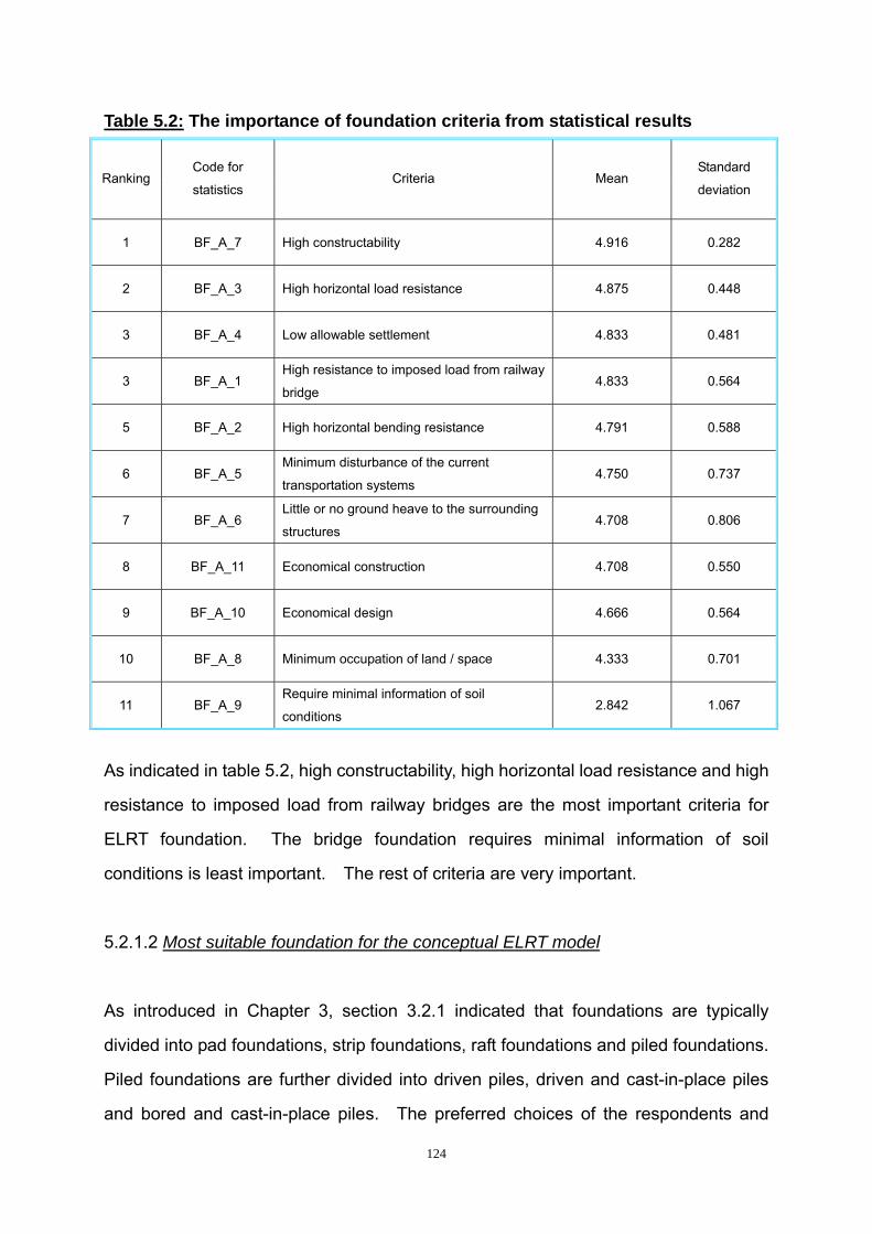
124
Table 5.2: The importance of foundation criteria from statistical results
Ranking Code for
statistics Criteria Mean
Standard
deviation
1 BF_A_7 High constructability 4.916 0.282
2 BF_A_3 High horizontal load resistance 4.875 0.448
3 BF_A_4 Low allowable settlement 4.833 0.481
3 BF_A_1 High resistance to imposed load from railway
bridge 4.833 0.564
5 BF_A_2 High horizontal bending resistance 4.791 0.588
6 BF_A_5 Minimum disturbance of the current
transportation systems 4.750 0.737
7 BF_A_6 Little or no ground heave to the surrounding
structures 4.708 0.806
8 BF_A_11 Economical construction 4.708 0.550
9 BF_A_10 Economical design 4.666 0.564
10 BF_A_8 Minimum occupation of land / space 4.333 0.701
11 BF_A_9 Require minimal information of soil
conditions 2.842 1.067
As indicated in table 5.2, high constructability, high horizontal load resistance and high
resistance to imposed load from railway bridges are the most important criteria for
ELRT foundation. The bridge foundation requires minimal information of soil
conditions is least important. The rest of criteria are very important.
5.2.1.2 Most suitable foundation for the conceptual ELRT model
As introduced in Chapter 3, section 3.2.1 indicated that foundations are typically
divided into pad foundations, strip foundations, raft foundations and piled foundations.
Piled foundations are further divided into driven piles, driven and cast-in-place piles
and bored and cast-in-place piles. The preferred choices of the respondents and
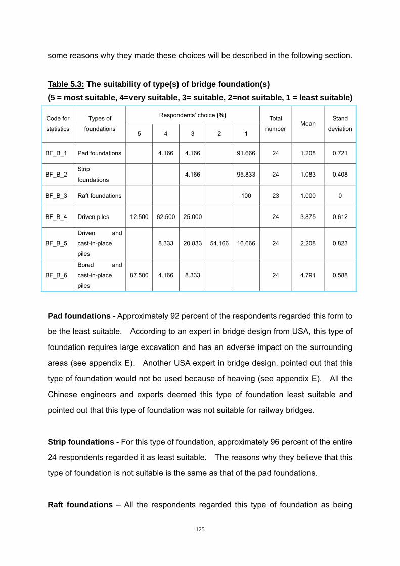
125
some reasons why they made these choices will be described in the following section.
Table 5.3: The suitability of type(s) of bridge foundation(s) (5 = most suitable, 4=very suitable, 3= suitable, 2=not suitable, 1 = least suitable)
Respondents’ choice (%) Code for
statistics
Types of
foundations 5 4 3 2 1
Total
number Mean
Stand
deviation
BF_B_1 Pad foundations 4.166 4.166 91.666 24 1.208 0.721
BF_B_2 Strip
foundations 4.166 95.833 24 1.083 0.408
BF_B_3 Raft foundations 100 23 1.000 0
BF_B_4 Driven piles 12.500 62.500 25.000 24 3.875 0.612
BF_B_5
Driven and
cast-in-place
piles
8.333 20.833 54.166 16.666 24 2.208 0.823
BF_B_6
Bored and
cast-in-place
piles
87.500 4.166 8.333 24 4.791 0.588
Pad foundations - Approximately 92 percent of the respondents regarded this form to
be the least suitable. According to an expert in bridge design from USA, this type of
foundation requires large excavation and has an adverse impact on the surrounding
areas (see appendix E). Another USA expert in bridge design, pointed out that this
type of foundation would not be used because of heaving (see appendix E). All the
Chinese engineers and experts deemed this type of foundation least suitable and
pointed out that this type of foundation was not suitable for railway bridges.
Strip foundations - For this type of foundation, approximately 96 percent of the entire
24 respondents regarded it as least suitable. The reasons why they believe that this
type of foundation is not suitable is the same as that of the pad foundations.
Raft foundations – All the respondents regarded this type of foundation as being
126
least suitable. The reasons why they believe this type of foundation is not suitable is
the same as that of the pad foundations.
Driven piles - Among the 24 respondents, 12.5 percent of them regarded this type of
foundation as most suitable, 62.5 percent of them regarded this type as very suitable
and 25 percent of them regarded this type as suitable. One USA expert in bridge
design (see appendix E) regarded driven piles as being the most suitable and stated
that driven piles have good quality control of materials. The other USA expert (see
appendix E) mentioned that driven piles are a reliable foundation type with more
capacity and less settlement and is also suitable for seismic applications. Most of
the engineers and experts believed the driven piles were very suitable and explained
their reasons as low costs and constructability. However the vibration and the noise
are a little bit high during construction. Another USA expert in bridge design (see
appendix E) indicated that driven piles were suitable because they require a large pile
cap to distribute loads and bending moments from the bridge girders. According to a
Chinese expert in railway and bridge construction (see appendix E), indicated that, for
driven piles, the negative force of friction will work in the long-term, which will restrict
the settlement. Chapter 3, section 3.2.1.2.5 pointed out that the construction of
driven piles will generate ground heave which may damage the adjacent structures.
Driven and cast-in-place piles - Approximately 54 percent of the 24 respondents
regarded this type of foundation as not suitable. Approximately 20 percent of the
respondents considered this type suitable and a smaller percent of respondent
thought that this type was least suitable. A USA expert in bridge design (see
appendix E) stated that driven piles were suitable because they require a large pile
cap to distribute loads and bending moments from the bridge girders. Another USA
expert in bridge design (see appendix E) expressed the same opinion and explained
that this type of foundation need a good quality programme. A third USA expert (see
appendix E) in bridge design indicated that this type of foundation was very suitable
and explained that it is a reliable foundation type with more capacity and less
127
settlement and is suitable for seismic applications. Some other engineers and
experts explained that the cost of this type of foundation was a somewhat high and
had a high vibration level. Besides noise and vibration, Chapter 3, section 3.2.12.5
mentioned that the ground displacement could damage adjacent structures. In
addition, this type of foundation cannot be used in construction with low headroom.
Bored and cast-in-place piles - For this type of foundation, 87.5 percent of the entire
respondents deemed this most suitable. An expert from the USA in bridge design
(see appendix E) regarded this type of foundation most suitable and emphasized that
the shaft extends above ground and becomes the pier shaft. This has very low
impact on surrounding transportation systems and areas around the ELRT. In
addition, this type of foundation can provide high resistance to loads and bending
moments from bridge girders. Another USA expert (see appendix E) in bridge design
stated that this type of foundation is suitable and explained that it needs a good quality
programme. Most of the engineers and experts felt that this type of foundation was
most suitable. They explained that bored and cast-in-place piles are strong and are
suitable for various soil conditions. During the construction procedure, low noise and
vibrations occurs, simple construction vehicles are needed, and cost is comparatively
low. One Chinese engineer in railway and bridge construction (see appendix E)
pointed out that the Tibet-Railway uses this type of foundation to solve the problem of
difficult soil conditions. Chapter 3, section 3.2.1.2.5 indicated that low noise and no
rise of ground heave happens with this type of foundation. Therefore, bored and
cast-in-place piles are the most suitable type for ELRT foundations for the conceptual
ELRT model.
Low noise and no ground heave enables bored and cast-in-place piles to be
constructed in the main lines with few disturbances to the nearby environments.
Large diameters and long lengths of shaft enable bored and cast-in-place piles to
stabilise and to resist heavy loads from the superstructure. However, the driven piles
can also be taken into consideration. Driven piles generate high noise and vibration
128
and they can only be used where there are not many structures nearby. Driven piles
can only be used when the soil conditions permit so that it can avoid the negative
force of friction for a long period. Under these circumstances, the main resistance of
driven piles needs to be end-bearing instead of fraction.
5.2.2 Suitable ELRT girder for the conceptual ELRT model
The questions concerning ELRT girders are divided into three sections. The first
concerns the criteria that need to be considered, the second concerns the suitable
type of ELRT girder to be chosen, the third concerns the suitable type of bridge to be
chosen. The following section will analyse these three sections separately.
5.2.2.1 Criteria for ELRT girders for the conceptual ELRT model
The importance of the criteria for ELRT girders are described as follows:
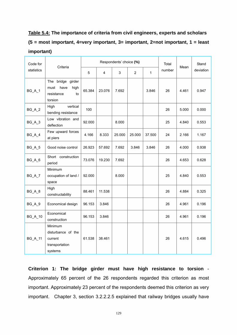
129
Table 5.4: The importance of criteria from civil engineers, experts and scholars
(5 = most important, 4=very important, 3= important, 2=not important, 1 = least
important)
Respondents’ choice (%) Code for
statistics Criteria
5 4 3 2 1
Total
number Mean
Stand
deviation
BG_A_1
The bridge girder
must have high
resistance to
torsion
65.384 23.076 7.692 3.846 26 4.461 0.947
BG_A_2 High vertical
bending resistance 100 26 5.000 0.000
BG_A_3 Low vibration and
deflection 92.000 8.000 25 4.840 0.553
BG_A_4 Few upward forces
at piers 4.166 8.333 25.000 25.000 37.500 24 2.166 1.167
BG_A_5 Good noise control 26.923 57.692 7.692 3.846 3.846 26 4.000 0.938
BG_A_6 Short construction
period 73.076 19.230 7.692 26 4.653 0.628
BG_A_7
Minimum
occupation of land /
space
92.000 8.000 25 4.840 0.553
BG_A_8 High
constructability 88.461 11.538 26 4.884 0.325
BG_A_9 Economical design 96.153 3.846 26 4.961 0.196
BG_A_10 Economical
construction 96.153 3.846 26 4.961 0.196
BG_A_11
Minimum
disturbance of the
current
transportation
systems
61.538 38.461 26 4.615 0.496
Criterion 1: The bridge girder must have high resistance to torsion -
Approximately 65 percent of the 26 respondents regarded this criterion as most
important. Approximately 23 percent of the respondents deemed this criterion as very
important. Chapter 3, section 3.2.2.2.5 explained that railway bridges usually have

130
to carry derailment load and lateral rolling forces from trains. These loads cause
large torsion to the bridge girder. Therefore, the bridge girder needs to have a high
resistance to torsion.
Criterion 2: The bridge girder should have high vertical bending resistance - All
the respondents regard this criterion as most important. Chapter 3, section 3.2.1.2
explained that imposed loads accounted for two-thirds of the dead load for railway
bridges. Chapter 3, section 3.2.2.2.5 also indicated that increased live loads from
trains are significantly larger than the loads from trucks used in a typical highway
design. Therefore, the bridge girder should have a high vertical bending resistance.
Criterion 3: The bridge girder should have low vibration and deflection - For this
criterion, 92 percent of the respondents believed it was most important. Chapter 3,
section 3.2.2.2.5 emphasized that the limitations established for vibrations and
deflections for rail structures are more stringent than typical for highway loading due
to the sensitivity of the train operations to structural moment forces.
Criterion 4: The bridge girder should have few upward forces at piers - For this
criterion, 25 percent of the respondents indicated that it is important. The same
percentage of the respondents regarded it as not important and 37.5 percent of the
respondent deemed it least important. However, Chapter 3, section 3.2.2.2.5
pointed out that the location of the train on the bridge would result in more frequent
occurrences of upward forces at the piers that must be addressed in the
superstructure to substructure connection.
Criterion 5: The bridge girder should have good noise control - Approximately 27
percent of the respondents regarded this criterion as most important and
approximately 58 percent of the respondents deemed this criterion as very important.
Chapter 3, section 3.2.2.2.5 explained that the noise level created by trains is often a
concern in areas where the alignment passes through residential areas, commercial
131
areas, or parklands.
Criterion 6: The bridge girder should have a short construction period -
Approximately 73 percent of the respondents regarded this criterion as most important
and approximately 19 percent of the respondents deemed this criterion as very
important. The conceptual ELRT model is supposed to travel along the main
transport routes, therefore the shorter the construction period the fewer disturbances
to the existing road network.
Criterion 7: The bridge girder should occupy minimum of land/space - Of all the
respondents, 92 percent regarded this criterion as most important. The conceptual
ELRT model is supposed to be located on the main transport routes where the current
public transport network is operating. The less the public space is occupied during
the construction procedure, the fewer the disturbances to the existing road network.
Criterion 8: The bridge girder should have high constructability - Approximately
88 percent of respondents regarded this criterion as being most important. Easy and
fast construction can make the construction process of bridge girders more
economical.
Criterion 9: The bridge girder should have an economical design - Approximately
96 percent of the respondents regarded this criterion as most important. The rest of
the respondents deemed this criterion as being very important. Economical design
helps to reduce the cost without adverse affects to the stability of the whole system.
Criterion 10: It should be economical to construct a bridge girder - Approximately
96 percent of the respondents regarded this criterion as most important. The rest of
the respondents deemed this criterion as being very important. Economical
construction helps to reduce the cost without adverse effects to the quality of the
whole system.

132
Criterion 11: The bridge girder construction should cause minimum disturbance
to the current transportation systems - Approximately 62 percent of the
respondents regarded this criterion as being most important. The rest of the
respondents deemed this criterion as being very important.
Table 5.5: The importance of girder criteria from statistical results
Ranking Code for
statistics Criteria Mean
Standard
deviation
1 BG_A_2 High vertical bending resistance 5.000 0.000
2 BG_A_9 Economical design 4.961 0.196
2 BG_A_10 Economical construction 4.961 0.196
4 BG_A_8 High constructability 4.884 0.325
5 BG_A_3 Low vibration and deflection 4.840 0.553
5 BG_A_7 Minimum occupation of land / space 4.840 0.553
7 BG_A_6 Short construction period 4.653 0.628
8 BG_A_11 Minimum disturbance of the current
transportation systems 4.615 0.496
9 BG_A_1 The bridge girder must have high resistance
to torsion 4.461 0.947
10 BG_A_5 Good noise control 4.000 0.938
11 BG_A_4 Few upward forces at piers 2.166 1.167
As indicated in table 5.5, high vertical bending resistance is most important criterion
for ELRT girder. The criteria of economic design, economical construction, low
vibration and deflection and minimum occupation of land / space are also very
important. The criterion of few uplift forces at piers is least important. The rest of
criteria are very important.
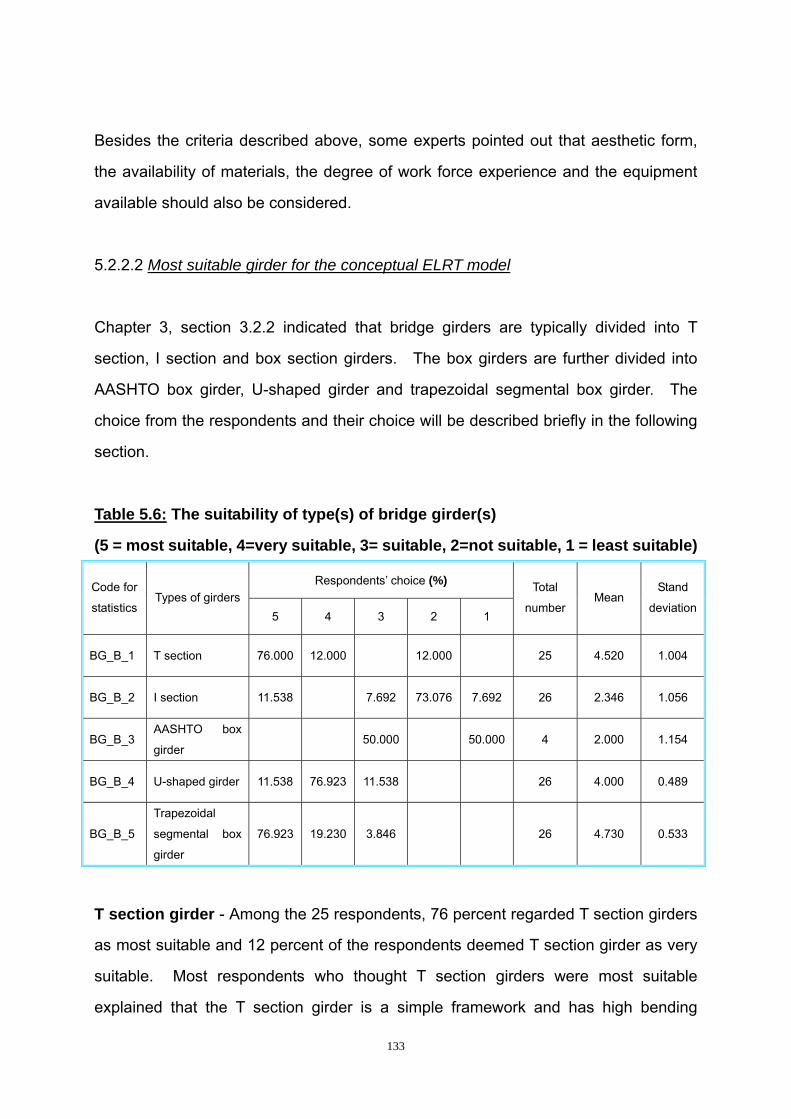
133
Besides the criteria described above, some experts pointed out that aesthetic form,
the availability of materials, the degree of work force experience and the equipment
available should also be considered.
5.2.2.2 Most suitable girder for the conceptual ELRT model
Chapter 3, section 3.2.2 indicated that bridge girders are typically divided into T
section, I section and box section girders. The box girders are further divided into
AASHTO box girder, U-shaped girder and trapezoidal segmental box girder. The
choice from the respondents and their choice will be described briefly in the following
section.
Table 5.6: The suitability of type(s) of bridge girder(s)
(5 = most suitable, 4=very suitable, 3= suitable, 2=not suitable, 1 = least suitable)
Respondents’ choice (%) Code for
statistics Types of girders
5 4 3 2 1
Total
number Mean
Stand
deviation
BG_B_1 T section 76.000 12.000 12.000 25 4.520 1.004
BG_B_2 I section 11.538 7.692 73.076 7.692 26 2.346 1.056
BG_B_3 AASHTO box
girder 50.000 50.000 4 2.000 1.154
BG_B_4 U-shaped girder 11.538 76.923 11.538 26 4.000 0.489
BG_B_5
Trapezoidal
segmental box
girder
76.923 19.230 3.846 26 4.730 0.533
T section girder - Among the 25 respondents, 76 percent regarded T section girders
as most suitable and 12 percent of the respondents deemed T section girder as very
suitable. Most respondents who thought T section girders were most suitable
explained that the T section girder is a simple framework and has high bending

134
resistance. However, some engineers and experts emphasized that the T section
girder is not very torsionally stiff. ELRT bridges will need to follow the line around
curves, which need high resistance to torsion. Therefore, a T section girder is not
suitable for the high-speed railway nowadays.
I section girder - Approximately 73 percent of the 26 respondent regarded an
I-section bridge girder as not suitable. Those respondents who thought that an
I-section bridge girder is most suitable expressed the view that an I-section bridge
girder can be pre-cast and is very efficient in load capacity. However, most
respondents emphasized that I section bridge girders are not very torsionally stiff.
High resistance to torsion is needed for ELRT bridges to follow the line around curves.
In China, I section bridge girders are widely used for roadway bridges.
AASHTO box girder - Only 4 respondents showed the AASHTO box girder, as their
choice, because this type of box girder is typically used in the USA. Half of them
regarded AASHTO box girders as suitable and the other half deemed AASHTO box
girders as least suitable. Most of the respondents mentioned that AASHTO box
girders are usually expensive and it is hard to control cracking in the deck. AASHTO
box girders have a low resistance to torsion and the beam cannot be built to follow the
curves. Joints between beams can become fatigued with time so that beams are
working independently and not together. It is not very aesthetically appealing.
Chapter 3, section 3.2.2.2.1 also indicated that AASHTO box girders are not efficient
during the construction process. Therefore, AASHTO box girders will not be suitable
for ELRT.
U-shaped girder - Approximately 77 percent of the 26 respondents regarded
U-shaped girder as very suitable. Approximately 12 percent of the respondents
deemed U-shaped girders as most suitable. Those who regarded U-shaped girders
to be most suitable explained that the U-shaped girders fit very well with ELRT
geometry, because it can follow curves. Each U-girder gets placed under each track.

135
U-shaped girder can be pre-cast or cast-in-place and have high resistance to torsion.
However, some respondents pointed out that U-shaped girders are usually expensive
and it is hard to control cracking in the deck. Some engineers or experts from China
emphasized that U-shaped girders are widely used for roadway bridges. Chapter 3,
section 3.2.2.2.1 indicates that the deck of U-shaped girders needs to be formed in
the field which adds to cost and construction time.
Trapezoidal segmental box girder - Approximately 77 percent of the 26 respondents
regarded trapezoidal segmental box girders as most suitable and approximately 19
percent of the respondents deem trapezoidal segmental box girder as very suitable.
Most of the respondents believed that trapezoidal segmental box girders are most
suitable. They explained that trapezoidal segmental box girders can be very quick to
construct, have high resistance to bending and torsion, and is good at resisting the
eccentric loads from trains. However, a USA expert in bridge design (see appendix
E) pointed out that trapezoidal segmental box girders are not as flexible in following
the tracks, since both tracks would be located on one box girder. A Chinese expert in
railway and bridge construction (see appendix E) suggested that a double-cell
trapezoidal segmental box girder be used instead of single-cell trapezoidal segmental
box girder. The suggestion solves the problem of the box girder not following the
tracks that the USA expert pointed out. Therefore, a double-cell trapezoidal
segmental box girder is the most suitable ELRT girder for the conceptual ELRT model.
The statistical results from the respondents showed that trapezoidal segmental box
girder is the best type. In order to have the best possible ELRT track geometry, the
girder can be located on two box girders. Hence, a double-cell trapezoidal
segmental box girder is the most suitable ELRT girder for the conceptual ELRT model.
5.2.2.3 Suitable bridge types for the conceptual ELRT model
After choosing the most suitable girder for the conceptual ELRT model, the bridge

136
types for the conceptual ELRT model also need to be selected. There are typically
four types of bridges that are widely used in the world nowadays. They are simple
supported bridges, continuous bridges, cable stayed bridges and suspension bridges.
The choices and opinions of the engineers, experts or scholars will be presented in
the following section.
Table 5.7: The suitability of bridge type(s)
(5 = most suitable, 4=very suitable, 3= suitable, 2=not suitable, 1 = least suitable)
Respondents’ choice (%) Code for
statistics Types of bridge
5 4 3 2 1
Total
number Means
Stand
deviation
BG_C_1
Simple
supported
bridge
88.000 4.000 8.000 25 4.680 0.900
BG_C_2 Continuous
bridge 36.000 16.000 48.000 25 3.880 0.927
BG_C_3 Cable stayed
bridge 4.166 4.166 91.666 24 1.291 0.999
BG_C_4 Suspension
bridge 4.166 4.166 91.666 24 1.208 0.832
Simple supported bridge - Among the entire 25 respondents, 88 percent of them
deemed the simple supported bridge as being the most suitable. The reason for their
choice is that this type of bridge is easy to design and construct. The girders are
prefabricated in the factory and it is easy and quick to put up the bridge with few
disturbances to the nearby transportation network. However, some respondents
claim that multiple joints are needed at each pier, which increases the cost.
Continuous bridge - Among the 25 respondents, 36 percent of them regarded the
continuous bridge as most suitable, 16 percent of them deem it as very suitable, and
the rest of them regarded the continuous bridge as being suitable. Some
respondents indicated that the continuous bridge is very efficient regarding the use
materials because of load redistribution due to the structural continuity. Fewer joints
137
lead the cost effectiveness of continuous bridges. However, most respondents
emphasized that continuous bridges are typically cast-in-place and long periods of
support is necessary for the girders before they are stiff enough. Complex
equipment is needed for construction. The complex support tools and equipment will
affect the current transportation system. Because the conceptual ELRT model is
supposed to travel along the main transport routes, there needs to be minimal
disturbance to the existing transportation system. Therefore, continuous bridges are
not suitable for the conceptual ELRT model.
Cable stayed bridge - Approximately 92 percent of the 24 respondents regarded a
cable stayed bridge as least suitable. Most of the respondents explained that cable
stayed bridges are too expensive to construct. A cabled stayed bridge can only be
used if it is absolutely necessary. A cable stayed bridge can be used to span over
large areas, such as over a plaza or cross a river. The conceptual ELRT model is
supposed to travel inland and along the main transport routes. Therefore, there is no
need to use a cable stayed bridge.
Suspension bridge - Approximately 92 percent of the 24 respondents regard
suspension bridge as least suitable. Like cable stayed bridge, most of the
respondents deemed suspension bridge as being too expensive to construct.
Furthermore, it is even more expensive to build and it takes a longer time to construct
than a cable stay bridge over a plaza. Therefore, suspension bridges are not
suitable for the conceptual ELRT model.
Based on the statistical results, simple support bridges are most suitable for use in the
conceptual ELRT model. Although joints are needed at the piers, easy and fast
construction of a simple support bridge will make the conceptual ELRT model more
economical.
138
5.2.3 Suitable ELRT sleepers for the conceptual ELRT model
The questions concerning the ELRT sleepers were divided into two sections. The first
question dealt with the criteria that needed to be considered, the second concerns the
suitable type of ELRT sleeper for the conceptual ELRT model. The following section
will analyze the criteria and the suitable types of ELRT sleeper separately.
5.2.3.1 Criteria of ELRT sleepers for the conceptual ELRT model
The importance of the criteria for ELRT sleepers, as rated by respondents, are
indicated in table 5.8 and discussed thereafter.
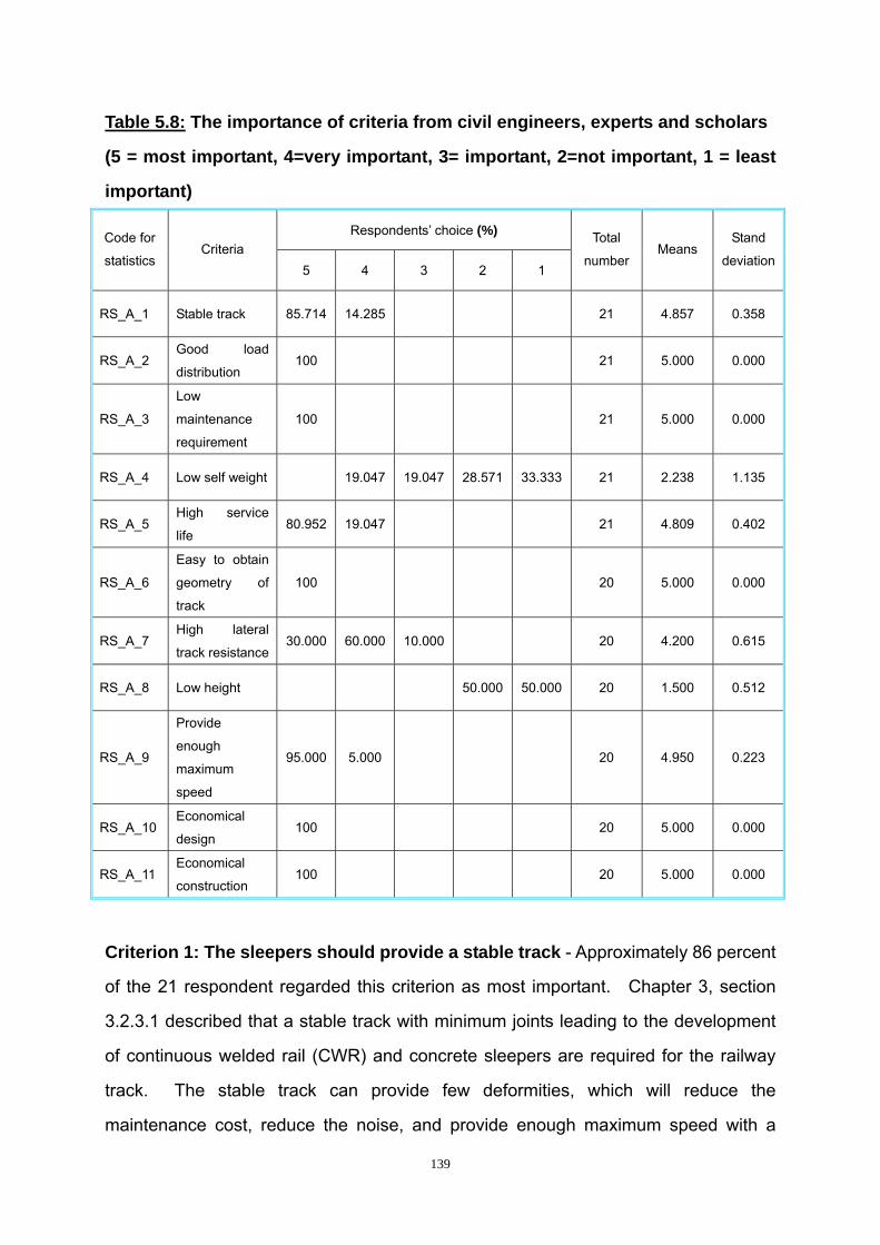
139
Table 5.8: The importance of criteria from civil engineers, experts and scholars
(5 = most important, 4=very important, 3= important, 2=not important, 1 = least
important)
Respondents’ choice (%) Code for
statistics Criteria
5 4 3 2 1
Total
number Means
Stand
deviation
RS_A_1 Stable track 85.714 14.285 21 4.857 0.358
RS_A_2 Good load
distribution 100 21 5.000 0.000
RS_A_3
Low
maintenance
requirement
100 21 5.000 0.000
RS_A_4 Low self weight 19.047 19.047 28.571 33.333 21 2.238 1.135
RS_A_5 High service
life 80.952 19.047 21 4.809 0.402
RS_A_6
Easy to obtain
geometry of
track
100 20 5.000 0.000
RS_A_7 High lateral
track resistance30.000 60.000 10.000 20 4.200 0.615
RS_A_8 Low height 50.000 50.000 20 1.500 0.512
RS_A_9
Provide
enough
maximum
speed
95.000 5.000 20 4.950 0.223
RS_A_10 Economical
design 100 20 5.000 0.000
RS_A_11 Economical
construction 100 20 5.000 0.000
Criterion 1: The sleepers should provide a stable track - Approximately 86 percent
of the 21 respondent regarded this criterion as most important. Chapter 3, section
3.2.3.1 described that a stable track with minimum joints leading to the development
of continuous welded rail (CWR) and concrete sleepers are required for the railway
track. The stable track can provide few deformities, which will reduce the
maintenance cost, reduce the noise, and provide enough maximum speed with a
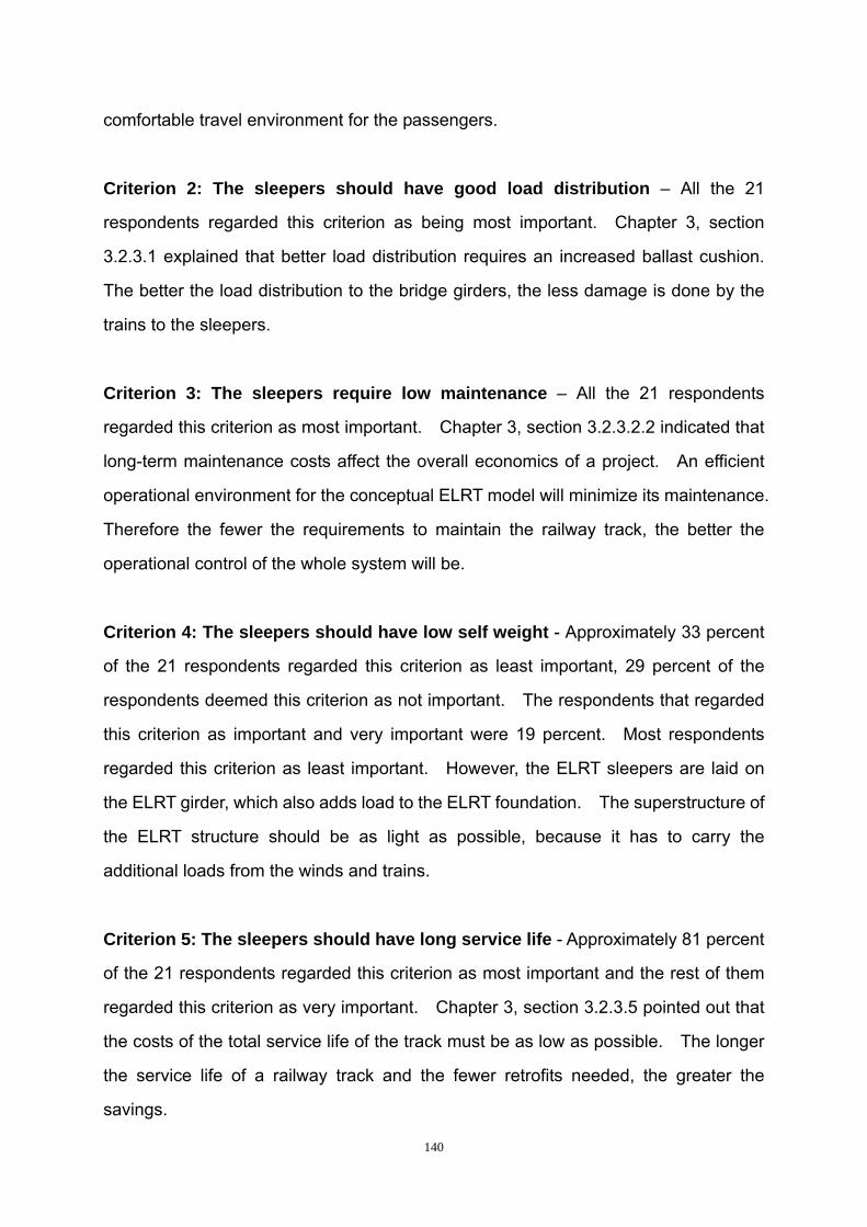
140
comfortable travel environment for the passengers.
Criterion 2: The sleepers should have good load distribution – All the 21
respondents regarded this criterion as being most important. Chapter 3, section
3.2.3.1 explained that better load distribution requires an increased ballast cushion.
The better the load distribution to the bridge girders, the less damage is done by the
trains to the sleepers.
Criterion 3: The sleepers require low maintenance – All the 21 respondents
regarded this criterion as most important. Chapter 3, section 3.2.3.2.2 indicated that
long-term maintenance costs affect the overall economics of a project. An efficient
operational environment for the conceptual ELRT model will minimize its maintenance.
Therefore the fewer the requirements to maintain the railway track, the better the
operational control of the whole system will be.
Criterion 4: The sleepers should have low self weight - Approximately 33 percent
of the 21 respondents regarded this criterion as least important, 29 percent of the
respondents deemed this criterion as not important. The respondents that regarded
this criterion as important and very important were 19 percent. Most respondents
regarded this criterion as least important. However, the ELRT sleepers are laid on
the ELRT girder, which also adds load to the ELRT foundation. The superstructure of
the ELRT structure should be as light as possible, because it has to carry the
additional loads from the winds and trains.
Criterion 5: The sleepers should have long service life - Approximately 81 percent
of the 21 respondents regarded this criterion as most important and the rest of them
regarded this criterion as very important. Chapter 3, section 3.2.3.5 pointed out that
the costs of the total service life of the track must be as low as possible. The longer
the service life of a railway track and the fewer retrofits needed, the greater the
savings.

141
Criterion 6: The sleepers should easily maintain the geometry of track – All the
20 respondents regarded this criterion as most important. The sleeper should easily
maintain the geometry of the track. If the geometry is maintained, it helps to stabilize
the railway track.
Criterion 7: The sleepers should have high lateral track resistance - Among the
20 respondents, 30 percent of them regarded this criterion as most important and 60
percent of them regarded it as very important. As introduced in Chapter 3, section
3.2.2.2.5, railway tracks should resist lateral rolling forces from trains. Hence, the
sleepers should have resistance to lateral forces. Furthermore, Chapter 3, section
3.2.3.2.1 discussed high lateral track resistance, which allows for future speed
increases. Therefore, the sleepers should have high lateral track resistance,
especially with the increase in the speed of trains in order to accommodate the
transportation environment of the future.
Criterion 8: The sleepers should have low height - Half of the respondents
regarded this criterion as least important and the other half deemed this criterion as
not important. For ELRT sleepers, the low height of the railway track goes with low
self-weight, which supports track stabilization.
Criterion 9: The sleepers should provide enough maximum speed - Among the
20 respondents, 95 percent of them regarded this criterion as most important and the
rest of them regarded it as very important. The higher the speeds that the sleepers
can support, the more stable the railway tracks will be. In order to accommodate the
higher speeds of the future, the sleeper should be designed to cope with maximum
speeds.
Criterion 10: The sleepers should be designed economically – All the 20
respondents regard this criterion as most important. Economical design helps to
142
reduce the cost, but it should be without adversely affecting the stability of the whole
system.
Criterion 11: The sleepers should be constructed economically – All the 20
respondents regarded this criterion as most important. Economical construction
helps to reduce the cost, but it should happen without adversely affecting the quality of
the whole system.
Table 5.9: The importance of railway sleeper criteria from statistical results
Ranking Code for
statistics Criteria Mean
Standard
deviation
1 RS_A_2 Good load distribution 5.000 0.000
1 RS_A_3 Low maintenance requirement 5.000 0.000
1 RS_A_6 Easy to obtain geometry of track 5.000 0.000
1 RS_A_10 Economical design 5.000 0.000
1 RS_A_11 Economical construction 5.000 0.000
6 RS_A_9 Provide enough maximum speed 4.950 0.223
7 RS_A_1 Stable track 4.857 0.358
8 RS_A_5 High service life 4.809 0.402
9 RS_A_7 High lateral track resistance 4.200 0.615
10 RS_A_4 Low self weight 2.238 1.135
11 RS_A_8 Low height 1.500 0.512
As indicated in table 5.9, the first five criteria are most important criterion for ELRT
sleeper and all the respondents completely agree that these criteria are of most

143
important. The criteria of low self weight and low height are the least important
criteria. The rest of the criteria are very important.
5.2.3.2 Most suitable types of sleepers and sleeper beds for the conceptual ELRT
model
As described in Chapter 3, section 3.2.3, the modern railway track is mainly divided
into ballasted track and non-ballasted type. Ballasted track use timber sleepers,
steel sleepers and pre-stressed concrete sleepers. The non-ballasted tracks are
divided into embedded tracks, pre-stressed concrete slabs and twin-block sleepers.
The choice of the respondents will be described in the following section.

144
Table 5.10: The suitability of type(s) of railway sleeper(s)
(5 = most suitable, 4=very suitable, 3= suitable, 2=not suitable, 1 = least suitable)
Respondents’ choice (%) Code for
statistics Types of sleepers
5 4 3 2 1
Total
number Mean
Stand
deviation
RS_B_1 Timber sleeper
(ballasted track) 4.761 95.238 21 1.095 0.436
RS_B_2 Steel sleeper
(ballasted track) 100 21 1.000 0.000
RS_B_3
Pre-stressed
concrete sleeper
(ballasted track)
28.571 71.428 21 4.285 0.462
RS_B_4
Embedded track
(non-ballasted
track)
4.761 95.238 21 1.095 0.436
RS_B_5
Pre-stressed
concrete slab
(non-ballasted
track)
19.047 76.190 4.761 21 4.142 0.478
RS_B_6
Twin-block
sleeper
(non-ballasted
track)
90.476 9.523 21 4.904 0.300
Timber sleepers on ballasted track - Approximately 95 percent of the entire
respondents regarded timber sleepers on ballasted track as least suitable. They
explained that the timber sleepers have poor durability and are not stable. Most of
the Chinese engineers or experts emphasized that timber sleepers are not used in the
main lines in China nowadays. Therefore, timber sleepers on ballasted track are not
suitable to be used for the conceptual ELRT model.
Steel sleepers on ballasted track – All the 21 respondents regarded steel sleepers
on ballasted track as least suitable. The respondents explained that steel sleeper
are very expensive and require a high level of maintenance. Therefore, steel
sleepers on ballasted track are also not suitable for the conceptual ELRT model.

145
Pre-stressed concrete sleeper on ballasted track - Approximately 29 percent of the
respondents regarded pre-stressed concrete sleepers as most suitable and the rest of
them deemed pre-stressed concrete sleeper as very suitable. Most of the
respondents explained that pre-stressed concrete sleepers have a long life cycle and
high durability. It is easy to construct pre-stressed concrete and it does not need
high technology. However, some respondents emphasized that constant tamping of
the ballast is needed to provide a stable track. The conceptual ELRT model is
supposed to carry passengers through the day and there is not much time left for
constant maintenance. Therefore, pre-stressed concrete sleepers on ballasted track
are not the best choice for the conceptual ELRT model.
Embedded track - Approximately 95 percent of the 21 respondents regard embedded
tracks as least suitable. Most of the respondents indicated that embedded track is
expensive with very high self-weight. Therefore, embedded tracks are not suitable
for used in the conceptual ELRT model.
Pre-stressed concrete slabs - Approximately 19 percent of the respondents
regarded pre-stressed concrete slabs as most suitable and approximately 76 percent
of them deemed pre-stressed concrete slab as very suitable. Most of the
respondents explained that pre-stressed concrete slabs can provide stable and
smooth tracks. Pre-stressed concrete slabs provide enough carrying capacity and is
suitable for the high-speed trains. However, some respondents emphasized that the
pre-stressed concrete slab is expensive and heavy. Therefore, cheaper sleepers
with low self-weight will be more suitable for the conceptual ELRT model.
Twin-block sleepers - Approximately 90 percent of the 21 respondents regarded
twin-block sleepers as most suitable, the rest of them deemed twin-block sleepers
very suitable. Most of the respondents explained that twin-block sleepers have a
long life cycle and high durability. The cost of twin-block sleepers is low and they can
provide a stable track. It is easy for twin-block sleepers to provide smooth and even

146
railway tracks. However, twin-blocks are not stiff enough to resist the loads from very
high speed trains. For the conceptual ELRT model that operates in the urban areas,
the speeds cannot reach more than 350 kilometres per hour, like that of the high
speed trains of Europe. Therefore, twin-block sleeper is the most suitable for used in
the conceptual ELRT model.
Based on the above-mentioned statistics and discussions, twin-block sleepers are the
best choice for the conceptual ELRT model. The railway tracks on a non-ballasted
type do not need constant tamping of the ballast as ballasted tracks do. Twin-block
sleepers can provide a stable and smooth track and they have a long life span and
high durability. Twin-block sleepers can also support enough maximum speed,
which makes them efficient. Twin-block sleepers are comparatively inexpensive,
which makes it possible to retrofit them in the future when new technologies of railway
sleepers are invented.
5.2.4 Suitability of ballasted or non-ballasted sleeper bed for the conceptual
model
As presented in Chapter 3, the sleeper bed is either ballasted or non-ballasted. The
function of the sleeper bed is to distribute the loads from railway sleepers to the
bridges. The purpose of the sleepers and the sleeper bed is to provide a stable
railway track, therefore the criteria for considering the sleeper bed should coincide
with that of the sleepers. Hence, the criteria for the suitability of ballasted or
non-ballasted track for the conceptual ELRT model do not need to be repeated in this
section. The following section will discuss the most suitable type of sleeper bed for
the conceptual ELRT model.
5.2.4.1 Most suitable type of sleeper bed
Table 5.10, code RS_B_6 shows that approximately 90 percent of the 21 respondents

147
regarded twin-block sleepers on a non-ballasted sleeper bed as the most suitable.
The remaining respondents deemed twin-block sleepers on a non-ballasted sleeper
bed very suitable. Chapter 3, section 3.2.3.2 confirms that non-ballasted railway
tracks needs low maintenance effort and have high availability. Compared with the
ballasted sleeper bed, the non-ballasted sleeper bed is more suitable for use in bridge
structures. This is especially suitable, since it requires less time for maintenance,
which suits urban areas due to the tight traffic schedules. These results and the
analysis from chapter 3 indicate that the twin-block sleeper on a non-ballasted sleeper
bed is most suitable for the conceptual ELRT model.
5.3 Summary and conclusions
In this chapter, the results of questionnaire surveys from the engineers, experts and
scholars were described. By analysing the opinions of the respondents, together
with the literature study of ELRT components, the verification and modification of the
most suitable civil engineering components for the conceptual ELRT model were
done.
From a long-term point of view, the conceptual ELRT model must have a long life span.
Therefore, the ELRT foundation and the ELRT girders should be sustainable for a
long period. The technology of railway tracks and sleepers are developing quickly.
Therefore, the ELRT sleepers should be comparatively inexpensive and easy to
retrofit in the future. At the same time, the ELRT sleepers should support sufficient a
maximum speed that will make it more efficient than other transportation systems.
Based on the choices and the opinions of civil engineers, experts and scholars,
together with the literature review of the suitable components for the conceptual ELRT
model, the most suitable types of components are concluded as follows with the main
reasons given for these choices:

148
Bored and cast-in-place piles are the most suitable ELRT foundation for the
following reasons: Firstly, they have very low impact on surrounding
transportation modes and areas around the ELRT. Secondly, they can
provide high resistance to loads and bending moments from bridge girders.
Thirdly, they have a strong ability that are suitable for various soil conditions.
Fourthly, they will generate low noise and vibration during the construction
procedure. Finally, they require simple construction vehicles and cost is
comparatively low.
Double-cell trapezoidal segmental box girders are the most suitable ELRT
girder type for the following reasons: Firstly, they are very quick to construct.
Secondly, they have a high resistance to bending and torsion, and are good at
resisting the eccentric loads from trains. Thirdly, they fit very well with ELRT
geometry because they can follow curves and a cell can be placed under each
track.
Twin-block sleepers on a non-ballasted sleeper bed are most suitable for the
conceptual ELRT model for the following reasons: Firstly, a non-ballasted
sleeper bed requires less maintenance. Secondly, twin-block sleepers on a
non-ballasted sleeper bed have a longer life cycle and are more durable.
Thirdly, twin-block sleepers are inexpensive and can provide a stable track.
Fourthly, twin-block sleepers control the smoothness of the railway track well.
Fifthly, twin-block sleepers on a non-ballasted sleeper bed can provide a high
enough maximum speed. Lastly, it is relatively inexpensive to remove
twin-block sleepers, which makes it possible to retrofit them at a later stage.

149
CHAPTER 6
EXPERTS’ REVIEW ON THE MOST SUITABLE CIVIL ENGINEERING
COMPONENTS FOR THE CONCEPTUAL ELRT MODEL
6.1 Introduction
Chapter 5 presented the most suitable civil engineering components for the
conceptual ELRT model, based on the literature studies, documentary analyses and
questionnaire survey. This chapter presents an expert review of the most suitable
ELRT components. The questionnaires, which were used for the expert review, were
sent to the civil engineers who had at least 10 years of working experience in their
respective fields. The views of some experts, who had been working for more than
20 years, were considered to be more valid than the views of less experienced and
younger civil engineers.
One American expert and four Chinese experts reviewed the civil engineering
components for the conceptual ELRT model, as was identified through previous
phases of this research. In this manner, the most suitable civil engineering
components were verified.
6.2 Most suitable civil engineering components for the conceptual ELRT model
The review of the most suitable civil engineering components for the conceptual ELRT
model is also divided into three parts, foundations, girders and sleepers, together with
the type of sleeper bed. Each component of the ELRT model was reviewed and the
report of the review is presented in the following sections.

150
6.2.1 Bored and cast-in-place piles
Through the literature studied, as well as through responses obtained by means of the
questionnaire surveys, it was determined that the most suitable foundation was bored
and cast-in-place piles. All the experts strongly agreed that the most suitable
foundation is bored and cast-in-place piles. They explained their opinions as follows
(see appendix G):
Firstly, bored and cast-in-place piles have a high resistance to loads,
inexpensive cost, and high constructability. The ELRT foundation needs to
resist high imposed loads from trains and wind loads, together with the
self-weight of the structure. The high resistance of bored and cast-in-place
piles will provide a stable foundation for the conceptual ELRT model and will
ensure a long life cycle. The budget of a structure helps to evaluate the
feasibility of a specific project.
Secondly, bored and cast-in-place piles are suitable for various soil conditions
and can be fabricated to various diameters and lengths. The main
characteristic of bored and cast-in-place piles is that they are suited to various
soil conditions, which means that this type of foundation can be easily adapted
to the requirements of many different projects. The fact that these piles can
be fabricated in various diameters and lengths makes it easy for bored and
cast-in-place piles to reach the hard and relatively incompressible layer of the
soil bearing stratum. This controls the resistance to the designed loads. In
addition, the piles lie on the hard and relatively incompressible layer of the soil
bearing stratum, which helps to control the allowable settlement and stabilise
the conceptual ELRT model.
Thirdly, during the construction procedure, the noises are low and have very
low impact on the surrounding areas. The disturbance to the surrounding
areas and structures need to be considered, especially with the conceptual
ELRT model, which is supposed to be located near the main transport line of
151
the road network. Less noise and very low impact to the nearby areas will
generate less environmental pollution. The most important advantage is that
the bored and cast-in-place piles will not compress the surrounding soil which
in turn, will not cause ground heave to the nearby structures.
6.2.2 A double-cell trapezoidal segmental box girder
Through the literature studied as well as the responses obtained by means of the
questionnaire survey, it was determined that a double-cell trapezoidal segmental box
girder is the most suitable ELRT girder. All the experts strongly agreed with the
opinion that a double-cell segmental trapezoidal segmental box girder is the most
suitable ELRT girder.
A Chinese expert (see appendix G) explained that, in comparison with the typical
railway bridge girders; box girders have the high stiffness, high durability, succinct
girder forms and are easily maintained. He further indicated that the high speed
railways plan to use trapezoidal box girders in most parts of the world, especially for
passenger transport. Another Chinese expert (see appendix G) confirmed that
double-cell segmental trapezoidal segmental box girders fit very well into double-line
railway geometry. As analysed in Chapter 3, box girders are stiffer than that of T
section and I section girders. High durability enables this type of bridge girder to be
used over a long period. Easy maintenance of this type of girder will reduce the
maintenance cost. Each single cell in a double-cell trapezoidal segmental box girder
provides one integrated structure to resist the loads from the trains of each line.
Therefore, a double-cell trapezoidal segmental box girder is best suited to the
conceptual ELRT model.
6.2.3 Twin-block sleepers on a non-ballasted sleeper bed
Through the literature studied as well as the responses obtained by means of the
152
questionnaire surveys, it was determined that twin-block sleepers on a non-ballasted
track were the most suitable for the conceptual ELRT model. All the experts strongly
agreed with the opinion that non-ballasted tracks with twin-block sleepers were the
most suitable railway track for the conceptual ELRT model. The experts explained
their opinions as follows (see appendix G):
Firstly, a non-ballasted sleeper bed can avoid the constant maintenance that a
ballasted sleeper bed needs. LRT systems need to carry passengers most
times of the day and are left with less time for the maintenance of the railway
track. According to Bonnett (2005: 81) urban railways have a tight clearance
and trains are frequent, therefore maintenance is not usually possible during
traffic hours. The maintenance has to be organized for night-time, when
there is no traffic. Therefore, a non-ballasted sleeper bed can help to save
the high costs of maintenance and ensure uninterrupted traffic flow.
Secondly, twin-block sleepers are comparatively inexpensive, have a long life
span and high durability. Although the twin-block sleepers cannot
accommodate the maximum speed found in high speed railways (350km/h),
twin-block sleepers can support sufficient maximum train speed for urban LRT.
The inexpensive costs of twin-block sleepers will make the budget of the
conceptual ELRT model more economical. Long life spans and high
durability enable the twin-block sleepers to be used for long periods.
Sufficient speeds make the operational environment more efficient. Trains on
tracks built with twin-block sleepers on standard lines in France can reach up
to 200km /hour for 25 tonne axial loads and can reach up to 300 km/hour for
17 tonne axial loads (Fédération Internationale Du Béton, 2007: 2). The
twin-block sleepers can support speeds of approximately 200 km/hour, which
is fast enough for urban rail transport.
Thirdly, the technology of railway tracks has developed rapidly in recent years
and it will be necessary to retrofit the railway track in the future. Therefore,
inexpensive twin-block sleepers will make retrofitting possible in the future.

153
6.3 Summary and conclusions
This chapter reviewed the most suitable civil engineering components for the
conceptual ELRT model as confirmed by experts. By analysing the survey
information as presented by these experts, it was possible to verify the proposed most
suitable civil engineering components for the conceptual ELRT model as developed
from the questionnaire surveys and literature review.
The foundation and the bridge girder of the conceptual ELRT model should be stiff
enough for the long term, because they are of primary importance for the stability of
the conceptual ELRT model. The more stiffness the foundations and bridge girders
provide, the smoother will be the railway track. In addition, the stability of the
foundation and the bridge girder helps to minimize the effects of unpredictable
conditions such as hurricanes. Railway sleepers are the easiest parts for retrofitting
in most railway structures. Therefore, retrofitting of railway sleepers should be
considered for the future to meet the new transit need.
The views of the engineering experts helped to modify and verify the most suitable
civil engineering components for the conceptual ELRT model. These most suitable
civil engineering components for the conceptual ELRT model are: 1) bored and
cast-in-place piles as the most suitable foundation type; 2) double-cell trapezoidal
segmental box girders as the most suitable girder type; and 3) twin-block sleepers on
a non-ballasted sleeper bed as the most suitable track for the conceptual ELRT
model.

154
CHAPTER 7
CONCLUSIONS AND RECOMMENDATIONS FOR FUTURE
RESEARCH
7.1 Introduction
Electrically driven LRT systems have the advantage over internal-combustion driven
vehicles, for two reasons: 1) the increasing demand of energy consumption all around
the world; and 2) the environmental factors such as air pollution and the emission of
greenhouse gases.
However, traditional LRT systems mainly operate at ground level and interact with the
existing road network. Some successful LRT systems indicate that the success of an
LRT system depends heavily on close co-operation with the existing road networks.
Bangkok has already built an ELRT system to reduce its severe traffic congestion.
In order to determine the most suitable civil engineering components for the
conceptual ELRT model, technologies concerning ELRT foundation, ELRT girders
and ELRT sleepers and sleeper beds were analysed in this research and further
validated and verified by civil engineering experts.
7.2 Conclusions
Bored and cast-in-place piles are the most suitable ELRT foundations for the
conceptual ELRT model.
A double-cell trapezoidal segmental box girder is the most suitable ELRT girder for the
155
conceptual ELRT model.
Twin-block sleepers on a non-ballasted sleeper bed are the most suitable for the
conceptual ELRT model.
7.3 Recommendations for future research
This research focused on the technical aspect of the most suitable civil engineering
components for a conceptual ELRT model. Through determining the most suitable
civil engineering components for the conceptual ELRT model, this research presents
foundation technology, bridge girder technology and modern railway track technology.
However, in order to complete the conceptual ELRT model, further research is
recommended:
The socio-technical desirability of an ELRT system should be evaluated before
an ELRT project is undertaken
Socio-political aspects should be studied before an ELRT project is put into
practice
A proper route should be identified together with the feeder bus systems to
optimise the current transportation systems.
More detailed soil information is needed along the planned route before the
exact design of an ELRT foundation is carried out.
The exact dimensions for each component of the conceptual ELRT model
needs to be defined during the practical design procedure, together with the
other components for the conceptual ELRT model.
156
REFERENCE LIST
Allport, R. (2005). ‘Operating risk: The Achilles’ heel of major infrastructure projects’
Civil Engineering Journal. 13(10) pp.16-17.
American Public Transportation Association. (2002). This Is Light Rail Transit.
http://www.apta.com/ [accessed 12 March 2006].
Bachmann, H. (2003). ‘Modern Track Technologies’ The European Railway Review
Conference. Pfleiderer track systems, Manchester. (16 September).
http://www.pfleiderer-track.com/fileadmin/pfleiderer_track_systems/downloads/Prese
ntation_ERR_1003_02.pdf [accessed 7 January 2007].
Banister, D. (2005). Unsustainable transport: City transport in the new century.
Oxfordshire: Routledge.
Black, W. R. (2006). Social and Economic Factors in Transportation.
http://onlinepubs.trb.org/onlinepubs/millennium/00100.pdf [accessed 12 June 2006].
Bonnett, C. F. (2001). Practical railway engineering. London: Imperial College Press.
Bonnett, C. F. (2005). Practical railway engineering. 2nd ed. London: Imperial College
Press.
Chen, W. F. (1995). The Civil Engineering Handbook. Florida: CRC Press.
Chisholm, G. (2001). Design-Build Transit Infrastructure Projects in Asia and Australia.
USA: Transportation research board.
157
http://onlinepubs.trb.org/onlinepubs/tcrp/tcrp_rrd_53.pdf [accessed 8 December
2007].
Dwivedi, A.K., Bhargava, P. and Bhandari, N. M. (2006). ‘Temperature effects in the
design of concrete bridges’ Advances in Bridge Engineering. pp.567.
http:// www.iitr.ac.in/departments/CE/abe/555-568.pdf [accessed 9 January 2007].
Erie Community College. (2007). Two of the World’s most outstanding concrete
structures in a single Campus at ECC Chennai.
http://www.lntecc.com/documents/vignettes_of_ecc_records.pdf [accessed 8 January
2007].
Esveld, C. (1997). TRACK STRUCTURES IN AN URBAN ENVIRONMENT.
http://www.rail.tudelft.nl/Publications/urban.pdf [accessed 9 May 2007].
Esveld, C. (2001). MODERN RAILWAY TRACK. 2nd ed. Delft: MRT Productions.
http://www.esveld.com/MRT_Selection.pdf [accessed 1 May 2007].
Esveld, C. (2003). Recent developments in slab track.
http://www.rail.tudelft.nl/Publications/ERR_Slabtrack.pdf [accessed 7 January 2007].
Esveld, C. (2007). RECENT DEVELOPMENTS IN SLAB TRACK APPLICATION.
http://www.rail.tudelft.nl/Publications/RailTech_99.PDF [accessed 7 January 2007].
Fagan, M. (2007). Maximizing the Value of Commuter Rail Infrastructure: The
International Experience. Massachusetts: Senior Fellow Center for Business and
Government Harvard University.
http://www.cityup.org/jiangao/3-Mark%20Fagan-Urban-infra-china-conf.pdf [accessed
7 December 2007].

158
Fédération Internationale Du Béton. (2007). Precast Concrete Railway Track
Systems.
http://books.google.com/books?id=YeGn_1JnbCIC&printsec=frontcover&dq=speed+k
m+%22twin+block+sleeper%22&hl=zh-CN#PRA3-PA2,M1 [accessed 11 November
2007].
Fellows, R. & Liu, A. (2003). Research Methods for Construction. 2nd ed. Oxford:
Blackwell publishing company
Fumey, M. (2002). Feasibility study <<ballastless track>>.
http://www.uic.asso.fr/download.php/infra/Feasibility_study_Report_march_2002.pdf?
PHPSESSID=a5b0e6f7c7dbe28e32f4475eca4281bc [accessed 1 May 2007].
Ginn, S. (1998). AN OVERVIEW OF LIGHT RAIL TECHNOLOGY AND ITS
POTENTIAL WITHIN AN AUSTRALIAN ENVIRONMENT.
http://www.wapc.wa.gov.au/Publications/Downloads_GetFile.aspx?id=44 [accessed 1
May 2006].
Hoyt, P. (1988) ‘Sacramento Light Rail: Lessons and Advice’ In: Attoe, W. Transit,
Land Use & Urban Form. Austin: Center for the Study of American Architecture. pp.
101-106.
Hubbell, J. & Colquhoun, D. (2006). ‘Light Rail Transit in Calgary- The First 25
Years’ Joint International Light Rail Conference. Calgary transit: St. Louis. (8 April).
http://www.calgarytransit.com/Calgarys_LRT_1st_25Years_TRB%20_revised.pdf
[accessed 16 June 2006].
Kastenholz, F. (1991). SNMP Communications Services.
http://www.faqs.org/ftp/rfc/pdf/rfc1270.txt.pdf [accessed 8 May 2006].

159
Klaiber, F. W., Wipf, T. J. and Russo, F. M. (2004). Cost-Effective Practices for
Off-System and Local Interest Bridges. Washington, D. C.: Transportation research
board.
http://onlinepubs.trb.org/onlinepubs/nchrp/nchrp_syn_327.pdf [accessed 8 January
2007].
Kohls, A. R. & Urquhart, D. B. (2007). Design Challenges and Construction Benefits
of Precast Segmental Rail Bridges. USA: Figg Bridge, Inc.
http://www.arema.org/eseries/scriptcontent/custom/e_arema/library/2003_Conferenc
e_Proceedings/0022.pdf [accessed 11 January 2007].
Leedy, D. P. (2005). Practical Research: Planning and Design. 8th ed. New Jersey: Pearson Education Inc.
Light Rail Now. (2001). Most Light Rail Projects within Budget, on Time.
http://www.lightrailnow.org/myths/m_lrt009.htm [accessed 28 February 2006].
Liu, C. & Event, J. B. (2004). Soils and Foundations. 6th ed. New Jersey: Pearson
Education, Inc.
Ludvigh, E. (2004). ‘Mitigation of railway noise and vibration concentrating on the
“reducing at source” methods’ Railways. 1(2) pp. 6-7.
http://www.ce.tuiasi.ro/intersections/archive/2004/No2/No2_eng.pdf [accessed 6 May
2007].
Ma, Z. G., Tadros, M. K. and Sun, C. B. (2004). ‘Prestressed Concrete Box Girders
Made from Precast Concrete Unsymmetrical Sections’ Precast/Prestressed Concrete
Institute journal. pp. 80.
http://www.pci.org/pdf/publications/journal/2004/January-February/JL-04-JANUARY-F
EBRUARY-5.pdf [accessed 4 January 2007].

160
Mathur, R. & Negi, S. K. (2005). Innovative Track Systems under Development on
Foreign Railways. Pune: India Railway Institute of Civil Engineering.
http://www.iricen.gov.in/projects/525/innovative.pdf [accessed 1 May 2007].
Nelson Mandela Bay Municipality report (1988). LIGHT RAIL TRANSIT SYSTEM:
FEASIBILITY STUDY [EXTENSION AND REVISION]. Nelson Mandela Bay: Nelson
Mandela Bay Municipality.
Nelson Mandela Bay Municipality report (2006). PUBLIC TRANSPORT PLAN 2006.
Nelson Mandela Bay: Nelson Mandela Bay Municipality.
Nie, Y. Q. & Meng, G. W. (2004). Material Mechanics. Peking: China Machine Press.
Orton, A. (1988). The Way We Build Now. Hong Kong: E&FN Spon.
Ponnuswamy, S. (2004). ‘Ballastless Track for Urban Transit Lines’ The Institution of
Engineers (India) Journal. 85 pp. 149-158.
http://www.ieindia.org/publish/cv/1104/nov04cv1.pdf [accessed 31 December 2006].
Post, J. R. (1988) ‘The Portland Light Rail Experience’ In: Attoe, W. Transit, Land Use
& Urban Form. Austin: Center for the Study of American Architecture. pp. 63-72.
Project Management Office. (2004). Bridge Concept Technical Evaluation Report
Executive Summary. New York: Project Management Office.
http://www. peacebridgex.com/files/tech_ eval_rpt_040317.pdf [accessed 9 January
2007].
Railway Technology (2007). Bangkok Transit System Light Rail Route Extension,
Thailand. http://www.railway-technology.com/projects/bangkok/index.html [accessed

161
8 December 2007].
Rodrigue, J. (2005). Urban Transport Problems.
http://people.hofstra.edu/geotrans/ eng/ch6en/co nc6en/ch6c4en.html [accessed 12
March 2006].
Rodriguez, M. (2005). Superstructure: California-Mexico Practice.
http://seismic.cv.titech.ac.jp/committee/FIB/PDF/6-Chapter4.pdf [accessed 4 January
2007].
Schulz, D. (2002). Waterways & Bridges. http://www.iti.northwestern.edu/education/high_school_institute/2002/lectures/02july12.pdf [accessed 9 January 2007].
Tan, W. (2004). Practical Research Methods. 2nd ed. Singapore: Pearson Education
south Asia Pte Ltd.
Taplin, M. (1998). The History of Tramways and Evolution of Light Rail.
http://www.lrta.org/mrthistory.html, [accessed 12 March 2006].
Tassin, D. M. (2006). ‘Jean M. Muller: Bridge Engineer with Flair for the Art Form’
Precast/Prestressed Concrete Institute journal. pp 5-13.
http://www.pci.org/view_file.cfm?file=JL-06-MARCH-APRIL-6.pdf [accessed 11
January 2007].
The Urban Land Institute. (2001). Light Rail Transit Phoenix, Arizona.
http://www.valleymetro.org/rail/publications/Transit%20Oriented%20Development/09-
ULI%20Final%20Report.pdf, [accessed 1 May 2006].
The World Bank Group. (2002). Urban Transport Overview.
http://www.worldbank. org/transport/ut_ss.htm, [accessed 12 January 2006].

162
Tomlinson, M. J. (2001). Foundation Design and Construction. 7th ed. Essex: Pearson
Education Ltd.
University of Portsmouth. (2003). An Introduction to Bridge Design.
http://www.civl.port.ac.uk/design_thread/Level%204/Structural%20Design%20in%20
Practice/BRIDGES/Current/Intro%20to%20Bridge%20Design.%20Intorduction/IntroB
ridgeDes.pdf [accessed 9 January 2007].
Varghese, P. C. (2005). Foundation Engineering. New Delhi: Prentice-Hall of India
Private Limited.
Vasconcellos, E. A. (2001). Urban Transport, Environment and Equity. London:
Earthscan Publication Ltd.
Wehmeier, S. (2000). Oxford Advance Learner’s Dictionary. (6th ed.). Oxford: Oxford
University Express.
Xu, C. X. & He, P. L. (2006) Principle Design the Framework of Concrete. Peking:
Peking University Press.
Züblin Technology. (2007). ON THE TRACK WITH ZÜBLIN (2007).
http://technologie.zueblin.de/www/obj.nsf/0/181C2BB7343F13F8C12571FB002F542
C/$FILE/brochure-on-the-track-with-zueblin-2006.pdf [accessed 17 May 2007].
163
APPENDIX A
QUESTIONNAIRE ON THE MOST SUITABLE BRIDGE FOUNDATION
FOR THE CONCEPTUAL ELRT MODEL

164
QUESTIONNAIRE AMONG ENGINEERS/ EXPERTS ON THE MOST
SUITABLE TYPE OF BRIDGE FOUNDATION FOR THE CONCEPTUAL
ELEVATED LIGHT RAIL TRANSIT MODEL Please complete this questionnaire and send back to Eric [email protected] or fax +27(0)41-5049498 within two weeks after receiving it, but before 31st August. Your participation will be greatly appreciated.
Purpose of the questionnaire
The purpose of this questionnaire is to obtain the views of civil engineers
on the most suitable type of bridge foundation to be use for the
conceptual elevated light rail transit (ELRT) model.
BIOGRAPHICAL INFORMATION ON RESPONDENTS NAME: EMPLOYED BY: POSITION IN ORGANIZATION: QUALIFICATION: EXPERIENCE: years in the field of
Please turn page

165
Section A: CRITERIA FOR THE SUITABILITY OF BRIDGE
FOUNDATIONS FOR THE CONCEPTUAL ELRT MODEL
Please indicate what criteria you would use to determine the suitability of bridge
foundations and how important you rate each criterion. Use the scale of 5 = most
important to 1 = least important.
The criteria for selecting the most suitable forms of bridge foundations for the
conceptual ELRT model:
Importance of criterion
Criteria
Use as criterion? If yes, please
insert a cross X
5 4 3 2 1
High resistance to imposed load from railway bridge
High horizontal bending resistance
High horizontal load resistance
Low allowable settlement
Minimum disturbance of the current transportation systems
Little or no ground heave to the surrounding structures
High constructability
Minimum occupation of land / space
Require minimal information of soil conditions
Economical design

166
Economical construction
Any other criteria, please specify
Note: High constructability means easy and fast construction.
Please turn page

167
Section B: RATING THE SUITABILITY OF BRIDGE FOUNDATIONS
FOR THE CONCEPTUAL ELRT MODEL
In order to develop a conceptual ELRT model, it would be appreciated if you could
indicate which type(s) of bridge foundation(s) are the suitable for the conceptual ELRT
model.
Please indicate your choice(s) by means of an “X” on the appropriate column. Use
the scale of 5 -1 to indicate the suitability of the various types wherein 5 represents the
most suitable type and 1 the least suitable. Please indicate the reason(s) why you
regard a specific type(s) as suitable.
Indication of the suitability of type(s) of bridge foundation(s)
(5= most suitable …. 1= least suitable)
Indicate choice by means of an X
Types of foundations
5 4 3 2 1
Reason for choice
Pad foundations
Strip foundations
Raft foundations
Driven piles
Driven and cast-in-place piles
Piled foundations
Bored and cast-in-place piles
THANK YOU VERY MUCH FOR YOUR FEEDBACK AND SUPPORT

168
APPENDIX B
QUESTIONNAIRE ON THE MOST SUITABLE BRIDGE GIRDER FOR
THE CONCEPTUAL ELRT MODEL

169
QUESTIONNAIRE AMONG CIVIL ENGINEERS / EXPERTS ON THE
MOST SUITABLE TYPE OF BRIDGE AND GIRDER FOR THE
CONCEPTUAL ELEVATED LIGHT RAIL TRANSIT MODEL Please complete this questionnaire and send back to Eric [email protected] or fax +27(0)41-5049498 within two weeks after receiving it, but before 31st August. Your participation will be greatly appreciated.
PURPOSE OF THE QUESTIONNAIRE
The purpose of this questionnaire is to obtain the views of civil engineers
or experts on the most suitable type of girder and bridge to use for the
conceptual elevated light rail transit (ELRT) model.
BIOGRAPHICAL INFORMATION ON RESPONDENTS NAME: EMPLOYED BY: POSITION IN ORGANIZATION: QUALIFICATION: EXPERIENCE: years in the field of
Please turn page

170
Section A: CRITERIA FOR THE SUITABILITY OF BRIDGE GIRDERS
AND BRIDGE TYPES FOR THE CONCEPTUAL ELRT MODEL
Please indicate what criteria you would use to determine the suitability of bridge
girders and how important you rate each criterion. Use the scale of 5 = most
important to 1 = least important.
The criteria for selecting the most suitable forms of bridge girders and bridge types
for the conceptual ELRT model:
Importance of criterion (Please indicate with across X in the
appropriate column) Criteria
Use as criterion? If yes, please
insert a cross X 5 4 3 2 1
The bridge girder must have high resistance to torsion
High vertical bending resistance
Low vibration and deflection
Few upward forces at piers
Good noise control
Short construction period
Minimum occupation of land / space
High constructability
Economical design
Economical construction
Minimum disturbance of the current transportation systems

171
Any other criteria, please add to the list
Aesthetic form
Note: High constructability means easy and fast construction.
Please turn page
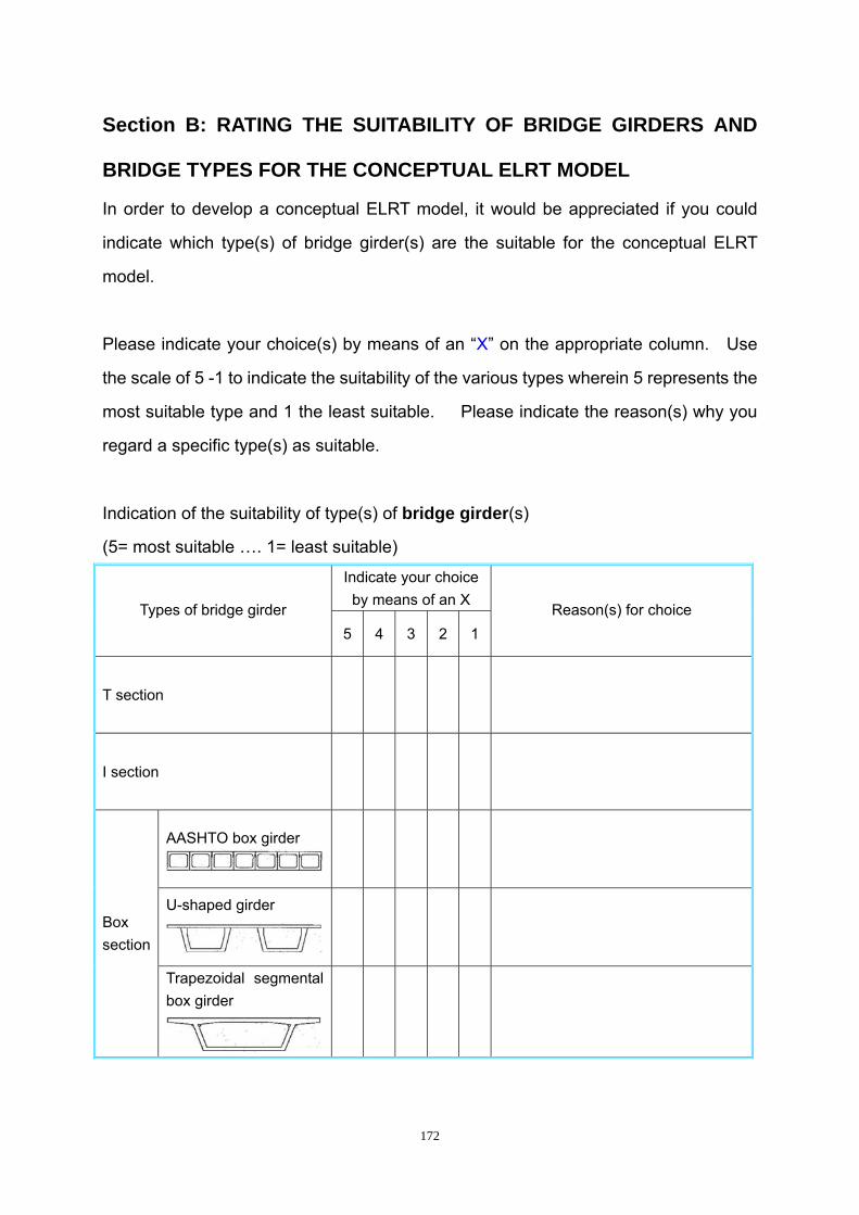
172
Section B: RATING THE SUITABILITY OF BRIDGE GIRDERS AND
BRIDGE TYPES FOR THE CONCEPTUAL ELRT MODEL
In order to develop a conceptual ELRT model, it would be appreciated if you could
indicate which type(s) of bridge girder(s) are the suitable for the conceptual ELRT
model.
Please indicate your choice(s) by means of an “X” on the appropriate column. Use
the scale of 5 -1 to indicate the suitability of the various types wherein 5 represents the
most suitable type and 1 the least suitable. Please indicate the reason(s) why you
regard a specific type(s) as suitable.
Indication of the suitability of type(s) of bridge girder(s)
(5= most suitable …. 1= least suitable)
Indicate your choice by means of an X
Types of bridge girder 5 4 3 2 1
Reason(s) for choice
T section
I section
AASHTO box girder
U-shaped girder
Box
section
Trapezoidal segmental box girder

173
Section C: Indication of the suitable of bridge type(s)
(5= most suitable …. 1= least suitable)
Type of bridge 5 4 3 2 1 Reason(s) for choice
Simple supported bridge
Continuous bridge
Cable stayed bridge
Suspension bridge
THANK YOU VERY MUCH FOR YOUR FEEDBACK AND SUPPORT

174
APPENDIX C
QUESTIONNAIRE ON THE MOST SUITABLE RAILWAY SLEEPER
FOR THE CONCEPTUAL ELRT MODEL

175
QUESTIONNAIRE AMONG ENGINEERS/ EXPERTS ON THE MOST
SUITABLE TYPE OF RAILWAY SLEEPER FOR THE CONCEPTUAL
ELEVATED LIGHT RAIL TRANSIT MODEL Please complete this questionnaire and send back to Eric [email protected] or fax +27(0)41-5049498 within two weeks after receiving it, but before 20th September. Your participation will be greatly appreciated.
PURPOSE OF THE QUESTIONNAIRE
The purpose of this questionnaire is to obtain the views of civil
engineering experts on the most suitable type of railway track with
sleeper for the conceptual elevated light rail transit (ELRT) model.
BIOGRAPHICAL INFORMATION ON RESPONDENTS NAME: EMPLOYED BY: POSITION IN ORGANIZATION: QUALIFICATION: EXPERIENCE: years in the field of
Please turn page

176
Section A: CRITERIA FOR THE SUITABILITY OF RAILWAY SLEEPER
FOR THE CONCEPTUAL ELRT MODEL
Please indicate what criteria you would use to determine the suitability of railway
sleepers and how important you rate each criterion. Use the scale of 5 = most
important to 1 = least important.
The criteria for selecting the most suitable forms of railway sleepers for the conceptual ELRT model:
Importance of criterion
Criteria
Use as criterion? If yes, please
insert a cross X
5 4 3 2 1
Stable track
Good load distribution
Low maintenance requirement
Low self weight
High service life
Easy to obtain geometry of track
High lateral track resistance
Low height
Provide enough maximum speed
Economical design
Economical construction
Any other criteria, please specify
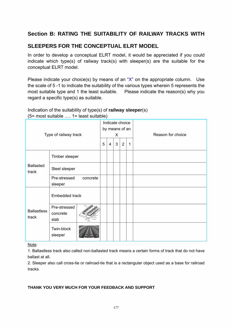
177
Section B: RATING THE SUITABILITY OF RAILWAY TRACKS WITH
SLEEPERS FOR THE CONCEPTUAL ELRT MODEL In order to develop a conceptual ELRT model, it would be appreciated if you could indicate which type(s) of railway track(s) with sleeper(s) are the suitable for the conceptual ELRT model. Please indicate your choice(s) by means of an “X” on the appropriate column. Use the scale of 5 -1 to indicate the suitability of the various types wherein 5 represents the most suitable type and 1 the least suitable. Please indicate the reason(s) why you regard a specific type(s) as suitable. Indication of the suitability of type(s) of railway sleeper(s) (5= most suitable …. 1= least suitable)
Indicate choice by means of an
X Type of railway track
5 4 3 2 1
Reason for choice
Timber sleeper
Steel sleeper Ballasted track
Pre-stressed concrete sleeper
Embedded track
Pre-stressed concrete slab
Ballastless track
Twin-block sleeper
Note: 1. Ballastless track also called non-ballasted track means a certain forms of track that do not have ballast at all. 2. Sleeper also call cross-tie or railroad-tie that is a rectangular object used as a base for railroad tracks. THANK YOU VERY MUCH FOR YOUR FEEDBACK AND SUPPORT

178
APPENDIX D
STATISTICAL RESULTS OF QUESTIONNAIRE SURVEYS

179
Frequency table: RegionCategory Count PercentUSAChinaAustraliaMissing
4 14.8148122 81.481481 3.703700 0.00000
Frequency table: PositionCategory Count PercentDirectorCivil engineerBridge engineerResearcherSenior civil engineerMissing
1 3.7037022 81.481482 7.407411 3.703701 3.703700 0.00000
Frequency table: QualCategory Count PercentDiplomaBachelorMasterDoctorMissing
2 7.4074120 74.074073 11.111111 3.703701 3.70370
Frequency table: ExperienceCategory Count Percent571011121320222328Missing
1 3.7037017 62.962961 3.703701 3.703701 3.703701 3.703701 3.703701 3.703701 3.703702 7.407410 0.00000
Descriptive Statistics
VariableMean Std.Dev Minimum Maximum N No.cases
MissingExperience 10.77778 6.896673 5.000000 28.00000 27 0

180
Frequency table: Field1Category Count PercentBridge designPrefabricate bridge girdersRailway and bridge constructionRailway and structuresMissing
7 25.925932 7.40741
17 62.962961 3.703700 0.00000
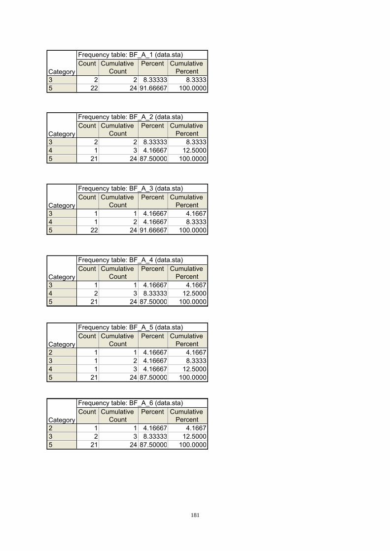
181
Frequency table: BF_A_1 (data.sta)
CategoryCount Cumulative
CountPercent Cumulative
Percent35
2 2 8.33333 8.333322 24 91.66667 100.0000
Frequency table: BF_A_2 (data.sta)
CategoryCount Cumulative
CountPercent Cumulative
Percent345
2 2 8.33333 8.33331 3 4.16667 12.5000
21 24 87.50000 100.0000
Frequency table: BF_A_3 (data.sta)
CategoryCount Cumulative
CountPercent Cumulative
Percent345
1 1 4.16667 4.16671 2 4.16667 8.3333
22 24 91.66667 100.0000
Frequency table: BF_A_4 (data.sta)
CategoryCount Cumulative
CountPercent Cumulative
Percent345
1 1 4.16667 4.16672 3 8.33333 12.5000
21 24 87.50000 100.0000
Frequency table: BF_A_5 (data.sta)
CategoryCount Cumulative
CountPercent Cumulative
Percent2345
1 1 4.16667 4.16671 2 4.16667 8.33331 3 4.16667 12.5000
21 24 87.50000 100.0000
Frequency table: BF_A_6 (data.sta)
CategoryCount Cumulative
CountPercent Cumulative
Percent235
1 1 4.16667 4.16672 3 8.33333 12.5000
21 24 87.50000 100.0000
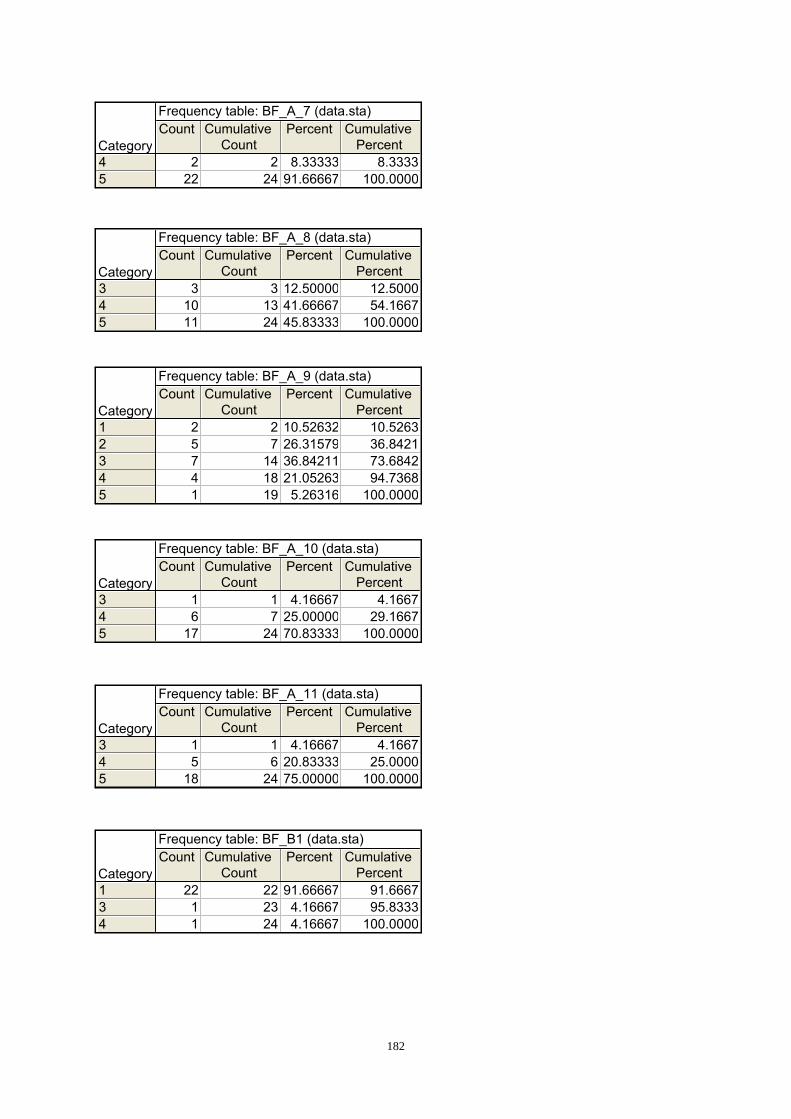
182
Frequency table: BF_A_7 (data.sta)
CategoryCount Cumulative
CountPercent Cumulative
Percent45
2 2 8.33333 8.333322 24 91.66667 100.0000
Frequency table: BF_A_8 (data.sta)
CategoryCount Cumulative
CountPercent Cumulative
Percent345
3 3 12.50000 12.500010 13 41.66667 54.166711 24 45.83333 100.0000
Frequency table: BF_A_9 (data.sta)
CategoryCount Cumulative
CountPercent Cumulative
Percent12345
2 2 10.52632 10.52635 7 26.31579 36.84217 14 36.84211 73.68424 18 21.05263 94.73681 19 5.26316 100.0000
Frequency table: BF_A_10 (data.sta)
CategoryCount Cumulative
CountPercent Cumulative
Percent345
1 1 4.16667 4.16676 7 25.00000 29.1667
17 24 70.83333 100.0000
Frequency table: BF_A_11 (data.sta)
CategoryCount Cumulative
CountPercent Cumulative
Percent345
1 1 4.16667 4.16675 6 20.83333 25.0000
18 24 75.00000 100.0000
Frequency table: BF_B1 (data.sta)
CategoryCount Cumulative
CountPercent Cumulative
Percent134
22 22 91.66667 91.66671 23 4.16667 95.83331 24 4.16667 100.0000

183
Frequency table: BF_B_2 (data.sta)
CategoryCount Cumulative
CountPercent Cumulative
Percent13
23 23 95.83333 95.83331 24 4.16667 100.0000
Frequency table: BF_B_3 (data.sta)
CategoryCount Cumulative
CountPercent Cumulative
Percent1 23 23 100.0000 100.0000
Frequency table: BF_B_4 (data.sta)
CategoryCount Cumulative
CountPercent Cumulative
Percent345
6 6 25.00000 25.000015 21 62.50000 87.50003 24 12.50000 100.0000
Frequency table: BF_B_5 (data.sta)
CategoryCount Cumulative
CountPercent Cumulative
Percent1234
4 4 16.66667 16.666713 17 54.16667 70.83335 22 20.83333 91.66672 24 8.33333 100.0000
Frequency table: BF_B_6 (data.sta)
CategoryCount Cumulative
CountPercent Cumulative
Percent345
2 2 8.33333 8.33331 3 4.16667 12.5000
21 24 87.50000 100.0000
Frequency table: BG_A_1 (data.sta)
CategoryCount Cumulative
CountPercent Cumulative
Percent1345
1 1 3.84615 3.84622 3 7.69231 11.53856 9 23.07692 34.6154
17 26 65.38462 100.0000
Frequency table: BG_A_2 (data.sta)
CategoryCount Cumulative
CountPercent Cumulative
Percent5 26 26 100.0000 100.0000

184
Frequency table: BG_A_3 (data.sta)
CategoryCount Cumulative
CountPercent Cumulative
Percent35
2 2 8.00000 8.000023 25 92.00000 100.0000
Frequency table: BG_A_4 (data.sta)
CategoryCount Cumulative
CountPercent Cumulative
Percent12345
9 9 37.50000 37.50006 15 25.00000 62.50006 21 25.00000 87.50002 23 8.33333 95.83331 24 4.16667 100.0000
Frequency table: BG_A_5 (data.sta)
CategoryCount Cumulative
CountPercent Cumulative
Percent12345
1 1 3.84615 3.84621 2 3.84615 7.69232 4 7.69231 15.3846
15 19 57.69231 73.07697 26 26.92308 100.0000
Frequency table: BG_A_6 (data.sta)
CategoryCount Cumulative
CountPercent Cumulative
Percent345
2 2 7.69231 7.69235 7 19.23077 26.9231
19 26 73.07692 100.0000
Frequency table: BG_A_7 (data.sta)
CategoryCount Cumulative
CountPercent Cumulative
Percent35
2 2 8.00000 8.000023 25 92.00000 100.0000
Frequency table: BG_A_8 (data.sta)
CategoryCount Cumulative
CountPercent Cumulative
Percent45
3 3 11.53846 11.538523 26 88.46154 100.0000
Frequency table: BG_A_9 (data.sta)
CategoryCount Cumulative
CountPercent Cumulative
Percent45
1 1 3.84615 3.846225 26 96.15385 100.0000

185
Frequency table: BG_A_10 (data.sta)
CategoryCount Cumulative
CountPercent Cumulative
Percent45
1 1 3.84615 3.846225 26 96.15385 100.0000
Frequency table: BG_A_11 (data.sta)
CategoryCount Cumulative
CountPercent Cumulative
Percent45
10 10 38.46154 38.461516 26 61.53846 100.0000
Frequency table: BG_B_1 (data.sta)
CategoryCount Cumulative
CountPercent Cumulative
Percent245
3 3 12.00000 12.00003 6 12.00000 24.0000
19 25 76.00000 100.0000
Frequency table: BG_B_2 (data.sta)
CategoryCount Cumulative
CountPercent Cumulative
Percent1235
2 2 7.69231 7.692319 21 73.07692 80.76922 23 7.69231 88.46153 26 11.53846 100.0000
Frequency table: BG_B_3 (data.sta)
CategoryCount Cumulative
CountPercent Cumulative
Percent13
2 2 50.00000 50.00002 4 50.00000 100.0000
Frequency table: BG_B_4 (data.sta)
CategoryCount Cumulative
CountPercent Cumulative
Percent345
3 3 11.53846 11.538520 23 76.92308 88.46153 26 11.53846 100.0000

186
Frequency table: BG_B_5 (data.sta)
CategoryCount Cumulative
CountPercent Cumulative
Percent345
1 1 3.84615 3.84625 6 19.23077 23.0769
20 26 76.92308 100.0000
Frequency table: BG_C_1 (data.sta)
CategoryCount Cumulative
CountPercent Cumulative
Percent235
2 2 8.00000 8.00001 3 4.00000 12.0000
22 25 88.00000 100.0000
Frequency table: BG_C_2 (data.sta)
CategoryCount Cumulative
CountPercent Cumulative
Percent345
12 12 48.00000 48.00004 16 16.00000 64.00009 25 36.00000 100.0000
Frequency table: BG_C_3 (data.sta)
CategoryCount Cumulative
CountPercent Cumulative
Percent145
22 22 91.66667 91.66671 23 4.16667 95.83331 24 4.16667 100.0000
Frequency table: BG_C_4 (data.sta)
CategoryCount Cumulative
CountPercent Cumulative
Percent125
22 22 91.66667 91.66671 23 4.16667 95.83331 24 4.16667 100.0000
Frequency table: RS_A_1 (data.sta)
CategoryCount Cumulative
CountPercent Cumulative
Percent45
3 3 14.28571 14.285718 21 85.71429 100.0000
Frequency table: RS_A_2 (data.sta)
CategoryCount Cumulative
CountPercent Cumulative
Percent5 21 21 100.0000 100.0000
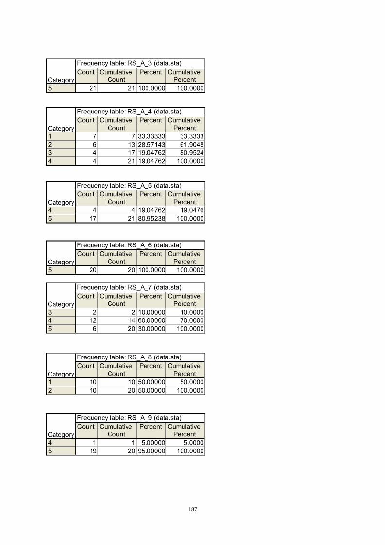
187
Frequency table: RS_A_3 (data.sta)
CategoryCount Cumulative
CountPercent Cumulative
Percent5 21 21 100.0000 100.0000
Frequency table: RS_A_4 (data.sta)
CategoryCount Cumulative
CountPercent Cumulative
Percent1234
7 7 33.33333 33.33336 13 28.57143 61.90484 17 19.04762 80.95244 21 19.04762 100.0000
Frequency table: RS_A_5 (data.sta)
CategoryCount Cumulative
CountPercent Cumulative
Percent45
4 4 19.04762 19.047617 21 80.95238 100.0000
Frequency table: RS_A_6 (data.sta)
CategoryCount Cumulative
CountPercent Cumulative
Percent5 20 20 100.0000 100.0000
Frequency table: RS_A_7 (data.sta)
CategoryCount Cumulative
CountPercent Cumulative
Percent345
2 2 10.00000 10.000012 14 60.00000 70.00006 20 30.00000 100.0000
Frequency table: RS_A_8 (data.sta)
CategoryCount Cumulative
CountPercent Cumulative
Percent12
10 10 50.00000 50.000010 20 50.00000 100.0000
Frequency table: RS_A_9 (data.sta)
CategoryCount Cumulative
CountPercent Cumulative
Percent45
1 1 5.00000 5.000019 20 95.00000 100.0000

188
Frequency table: RS_A_10 (data.sta)
CategoryCount Cumulative
CountPercent Cumulative
Percent5 20 20 100.0000 100.0000
Frequency table: RS_A_11 (data.sta)
CategoryCount Cumulative
CountPercent Cumulative
Percent5 20 20 100.0000 100.0000
Frequency table: RS_B_1 (data.sta)
CategoryCount Cumulative
CountPercent Cumulative
Percent13
20 20 95.23810 95.23811 21 4.76190 100.0000
Frequency table: RS_B_2 (data.sta)
CategoryCount Cumulative
CountPercent Cumulative
Percent1 21 21 100.0000 100.0000
Frequency table: RS_B_3 (data.sta)
CategoryCount Cumulative
CountPercent Cumulative
Percent45
15 15 71.42857 71.42866 21 28.57143 100.0000
Frequency table: RS_B_4 (data.sta)
CategoryCount Cumulative
CountPercent Cumulative
Percent13
20 20 95.23810 95.23811 21 4.76190 100.0000
Frequency table: RS_B_5 (data.sta)
CategoryCount Cumulative
CountPercent Cumulative
Percent345
1 1 4.76190 4.761916 17 76.19048 80.95244 21 19.04762 100.0000
Frequency table: RS_B_6 (data.sta)
CategoryCount Cumulative
CountPercent Cumulative
Percent45
2 2 9.52381 9.523819 21 90.47619 100.0000

189
Descriptive Statistics (data.sta)Variable Valid N Mean Median Minimum Maximum Std.Dev.BF_A_1BF_A_2BF_A_3BF_A_4BF_A_5BF_A_6BF_A_7BF_A_8BF_A_9BF_A_10BF_A_11BF_B1BF_B_2BF_B_3BF_B_4BF_B_5BF_B_6BG_A_1BG_A_2BG_A_3BG_A_4BG_A_5BG_A_6BG_A_7BG_A_8BG_A_9BG_A_10BG_A_11BG_B_1BG_B_2BG_B_3BG_B_4BG_B_5BG_C_1BG_C_2BG_C_3BG_C_4RS_A_1RS_A_2RS_A_3RS_A_4RS_A_5RS_A_6RS_A_7RS_A_8RS_A_9RS_A_10RS_A_11RS_B_1RS_B_2RS_B_3RS_B_4RS_B_5RS_B_6
24 4.833333 5.000000 3.000000 5.000000 0.56466024 4.791667 5.000000 3.000000 5.000000 0.58823024 4.875000 5.000000 3.000000 5.000000 0.44842724 4.833333 5.000000 3.000000 5.000000 0.48154324 4.750000 5.000000 2.000000 5.000000 0.73721024 4.708333 5.000000 2.000000 5.000000 0.80645024 4.916667 5.000000 4.000000 5.000000 0.28233024 4.333333 4.000000 3.000000 5.000000 0.70196419 2.842105 3.000000 1.000000 5.000000 1.06787224 4.666667 5.000000 3.000000 5.000000 0.56466024 4.708333 5.000000 3.000000 5.000000 0.55003324 1.208333 1.000000 1.000000 4.000000 0.72106024 1.083333 1.000000 1.000000 3.000000 0.40824823 1.000000 1.000000 1.000000 1.000000 0.00000024 3.875000 4.000000 3.000000 5.000000 0.61237224 2.208333 2.000000 1.000000 4.000000 0.83297124 4.791667 5.000000 3.000000 5.000000 0.58823026 4.461538 5.000000 1.000000 5.000000 0.94787226 5.000000 5.000000 5.000000 5.000000 0.00000025 4.840000 5.000000 3.000000 5.000000 0.55377524 2.166667 2.000000 1.000000 5.000000 1.16718426 4.000000 4.000000 1.000000 5.000000 0.93808326 4.653846 5.000000 3.000000 5.000000 0.62879625 4.840000 5.000000 3.000000 5.000000 0.55377526 4.884615 5.000000 4.000000 5.000000 0.32581326 4.961538 5.000000 4.000000 5.000000 0.19611626 4.961538 5.000000 4.000000 5.000000 0.19611626 4.615385 5.000000 4.000000 5.000000 0.49613925 4.520000 5.000000 2.000000 5.000000 1.00498826 2.346154 2.000000 1.000000 5.000000 1.0561184 2.000000 2.000000 1.000000 3.000000 1.154701
26 4.000000 4.000000 3.000000 5.000000 0.48989826 4.730769 5.000000 3.000000 5.000000 0.53349425 4.680000 5.000000 2.000000 5.000000 0.90000025 3.880000 4.000000 3.000000 5.000000 0.92736224 1.291667 1.000000 1.000000 5.000000 0.99909424 1.208333 1.000000 1.000000 5.000000 0.83297121 4.857143 5.000000 4.000000 5.000000 0.35856921 5.000000 5.000000 5.000000 5.000000 0.00000021 5.000000 5.000000 5.000000 5.000000 0.00000021 2.238095 2.000000 1.000000 4.000000 1.13599121 4.809524 5.000000 4.000000 5.000000 0.40237420 5.000000 5.000000 5.000000 5.000000 0.00000020 4.200000 4.000000 3.000000 5.000000 0.61558720 1.500000 1.500000 1.000000 2.000000 0.51298920 4.950000 5.000000 4.000000 5.000000 0.22360720 5.000000 5.000000 5.000000 5.000000 0.00000020 5.000000 5.000000 5.000000 5.000000 0.00000021 1.095238 1.000000 1.000000 3.000000 0.43643621 1.000000 1.000000 1.000000 1.000000 0.00000021 4.285714 4.000000 4.000000 5.000000 0.46291021 1.095238 1.000000 1.000000 3.000000 0.43643621 4.142857 4.000000 3.000000 5.000000 0.47809121 4.904762 5.000000 4.000000 5.000000 0.300793
190
APPENDIX E
SUMMARY OF RESPONSES FROM QUESTIONNAIRE SURVEYS

191
Summary of responses from questionnaire surveys Foundation
A. K., working 24 years in bridge design
Pad foundations Require large excavation, impact other transportation modes and surrounding areas. Require large areas to counteract bending moments from bridge girders
Strip foundations Same as for Pad Foundation
Raft foundations Same as for Pad Foundation
Driven piles Still would require a large pile cap to distribute loads and bending moments from the bridge girders
Driven and cast-in-place piles
Same as for driven piles Piled foundations
Bored and cast-in-place piles
If these are to be drilled shafts, where the shaft extends above ground and becomes the pier shaft. Very low impact on surrounding transportation modes and areas around the ELRT. Can provide high resistance to loads and bending moments from bridge girders.
J.D., working 28 years in structures
Pad foundations Wouldn’t use -- heaving
Strip foundations Wouldn’t use - heaving
Raft foundations Wouldn’t use - heaving
Driven piles Good quality control of materials
Driven and cast-in-place piles
Need good quality program Piled foundations
Bored and cast-in-place piles
Need good quality program

192
B.K., working 20 years
Driven piles Reliable foundation type with more capacity and less settlement. Suitable for seismic applications
Driven and cast-in-place piles
Reliable foundation type with more capacity and less settlement. Suitable for seismic applications
Piled foundations
Bored and cast-in-place piles
Augured pile is not common in WA
P. Z., working 28 years in railway and bridge construction
Pad foundations Not suitable for railway bridges.
Strip foundations Same as above.
Raft foundations Same as above
Driven piles Loud noise, easy construction procedure, low cost. However, the minus force of friction will take place in the long term; the allowable settlement is not easy to control.
Driven and cast-in-place piles
High vibration, cost is a little bit high. Piled foundations
Bored and cast-in-place piles
Suitable for various soil conditions and construction circumstances. Simple construction vehicles, low noise and vibration during the construction procedure, cost is comparatively low.
G. W., working 7 years in railway and bridge construction
Driven piles Low cost, noise is a little bit loud
Driven and cast-in-place piles
High vibration, the cost is a little bit high Piled foundations
Bored and cast-in-place piles
Low vibration, quick construction time, can be suitable for various conditions, Tibet-railway use this type of foundation.

193
Girder
A. K., working 24 years in bridge design
T section Not very torsionally stiff. ELRT bridges will need to follow line around curves
I section Not torsionally stiff. See above for explanation
AASHTO box girder
Beams can’t be built to follow curves – can only be placed on chords. Joints between beams can fatigue with time so that beam are working independently and not together. No very aesthetic from below
U-shaped girder Fit very well with ELRT geometry – can follow curves, one U-girder is placed under each track.
Box section
Trapezoidal segmental box girder
Can work, however not as flexible in following the tracks, since both tracks would be located on one box girder.
P. Z., working 28 years in railway and bridge construction
T section Simple framework, high bending resistance, but the torsional resistance is a little bit low, not suitable for high speed railway nowadays.
I section Widely used for roadway bridges.
AASHTO box girder American roadway girder, low resistance to torsion.
U-shaped girder High torsional resistance, typically prefabricate on site, thin plate at the bottom, widely used for roadway bridges.
Box section
Trapezoidal segmental box girder
High torsional resistance. Good at resist the eccentricity of loads from trains. I suggest using multiple cell segmental box girders which each track can lay on each cell.

194
APPENDIX F
EXPERT REVIEW OF SUITABLE CIVIL ENGINEERING
COMPONENTS FOR A CONCEPTUAL ELRT MODEL
195
EXPERT REVIEW OF SUITABLE CIVIL ENGINEERING
COMPONENTS FOR THE CONCEPTUAL ELRT
MODEL Please complete this review and send back to Eric [email protected] or fax +27(0)41-5049498 within one week after receiving it, but before 10th November. Your participation will be greatly appreciated.
Purpose of this review The purpose of this review is to obtain the opinions from experts on the civil engineering components that are regarded as most suitable for the conceptual ELRT (elevated light rail transit) model.
BIOGRAPHICAL INFORMATION OF RESPONDENTS NAME: EMPLOYED BY: POSITION IN ORGANIZATION: QUALIFICATION: EXPERIENCE: years in the field of MOST SUITABLE CIVIL ENGINEERING COMPONENTS FOR THE CONCEPTUAL ELRT MODEL Please review the following civil engineering components and indicate whether they are the most suitable for the conceptual ELRT model. If not, please express your opinion and give some reasons for either supporting or not supporting the selection of a specific component. These components are based on the literature studied as well as responses obtained by means of questionnaires from experts and practicing engineers and post graduate scholars.

196
Foundation The most suitable foundation is bored and cast-in-place piles. The reasons are as follows:
• Bored and cast-in-place piles have very low impact on surrounding transportation modes and areas around the ELRT;
• Bored and cast-in-place piles can provide high resistance to loads and bending
moments from bridge girders;
• Bored and cast-in-place piles have a strong ability that is suitable for various soil conditions;
• Bored and cast-in-place piles will generate low noise and vibration during the
construction procedure;
• Bored and cast-in-place piles require simple construction vehicles and cost is comparatively low.
Please tick (√) the appropriate blocks: My level of agreement to the above-mentioned choice is: Level of agreement / disagreement Tick here Strongly agree Agree Neutral Disagree Strongly disagree Reasons for agreement / disagreement:

197
Girder A double-cell trapezoidal segmental box girder is the most suitable ELRT girder for the following reasons.
• Double-cell trapezoidal segmental box girders can be very quick to construct;
• Double-cell trapezoidal segmental box girders
have a high resistance to bending and torsion; and is good at resisting the eccentric loads from trains;
• Double-cell trapezoidal segmental box girders fit very well with ELRT geometry
because they can follow curves. Each cell gets placed under each track. Please tick (√) the appropriate blocks: My level of agreement to the above-mentioned choice is: Level of agreement / disagreement Tick here Strongly agree Agree Neutral Disagree Strongly disagree Reasons for agreement / disagreement:
Sleeper Twin-block sleepers on a non-ballasted sleeper bed are the most suitable sleepers for an ELRT model because of the following reasons.
• Twin-block sleepers have a long life cycle and high durability;

198
• The cost of twin-block sleepers is low and can provide a stable track;
• It is easy for twin-block sleepers to control the smoothness of the railway track;
• Twin-block sleepers can provide a high enough maximum speed;
• Twin-block sleepers are comparatively inexpensive and easy to remove, which makes future retrofitting possible.
Please tick (√) the appropriate blocks: My level of agreement to the above-mentioned choice is: Level of agreement / disagreement Tick here Strongly agree Agree Neutral Disagree Strongly disagree Reasons for agreement / disagreement:
Thank you very much for your co-operation and sharing your expertise.
199
APPENDIX G
SUMMARY OF RESPONSES FROM EXPERT REVIEW
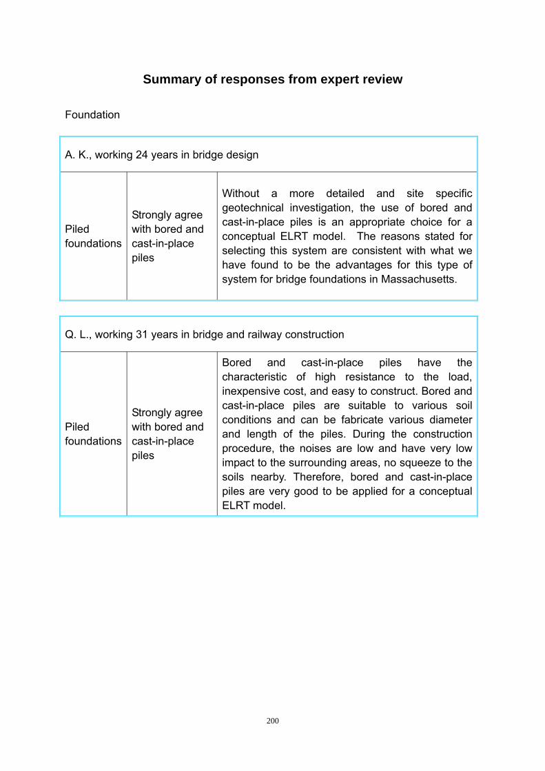
200
Summary of responses from expert review Foundation
A. K., working 24 years in bridge design
Piled foundations
Strongly agree with bored and cast-in-place piles
Without a more detailed and site specific geotechnical investigation, the use of bored and cast-in-place piles is an appropriate choice for a conceptual ELRT model. The reasons stated for selecting this system are consistent with what we have found to be the advantages for this type of system for bridge foundations in Massachusetts.
Q. L., working 31 years in bridge and railway construction
Piled foundations
Strongly agree with bored and cast-in-place piles
Bored and cast-in-place piles have the characteristic of high resistance to the load, inexpensive cost, and easy to construct. Bored and cast-in-place piles are suitable to various soil conditions and can be fabricate various diameter and length of the piles. During the construction procedure, the noises are low and have very low impact to the surrounding areas, no squeeze to the soils nearby. Therefore, bored and cast-in-place piles are very good to be applied for a conceptual ELRT model.

201
P. Z., working 28 years in bridge and railway construction
Piled foundations
Strongly agree with bored and cast-in-place piles
Bored and cast-in-place piles can be suitable for various soil conditions and construction circumstances. Low noise and vibration during the construction procedure. Simple construction vehicles and construction procedure enable this type of bridge foundation suitable for bridges located in the city. One other advantage of bored and cast-in-place piles is this type of foundation has very low impact to the surrounding areas. This type of foundation provides high resistance to the loads and the cost is this type foundation is inexpensive which make this type of foundation very suitable for ELRT foundation.
C. W., working 13 years in bridge and railway construction
Piled foundations
Strongly agree with bored and cast-in-place piles
Bored and cast-in-place piles have the characteristic of Low noise, low vibration, short construction period, easy access to get quality control, very suitable for ELRT foundation.
R. Z., working 11 years in bridge and railway construction
Piled foundations
Strongly agree with bored and cast-in-place piles
Bored and cast-in-place piles have the characteristic of Low noises, low cost, short construction period, and low vibration, suitable for ELRT foundation.
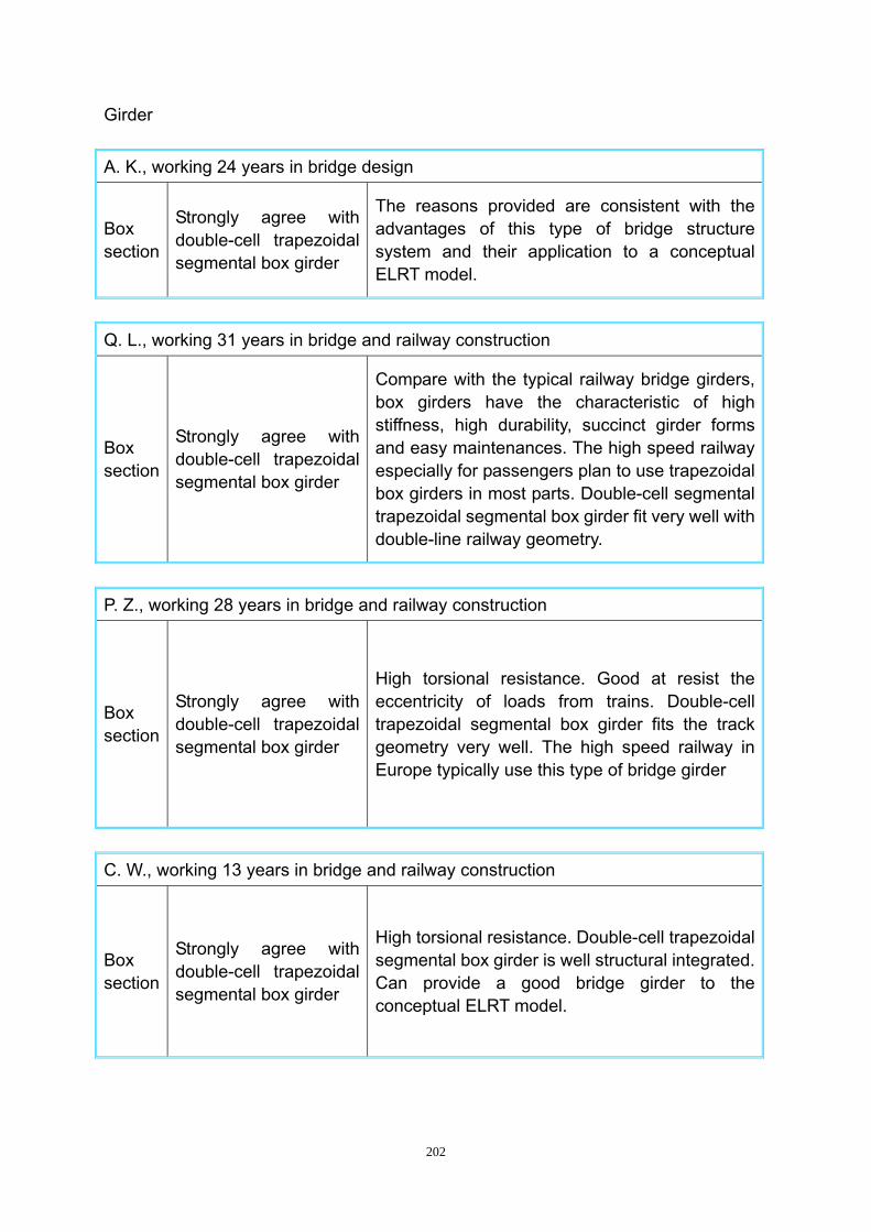
202
Girder
A. K., working 24 years in bridge design
Box section
Strongly agree with double-cell trapezoidal segmental box girder
The reasons provided are consistent with the advantages of this type of bridge structure system and their application to a conceptual ELRT model.
Q. L., working 31 years in bridge and railway construction
Box section
Strongly agree with double-cell trapezoidal segmental box girder
Compare with the typical railway bridge girders, box girders have the characteristic of high stiffness, high durability, succinct girder forms and easy maintenances. The high speed railway especially for passengers plan to use trapezoidal box girders in most parts. Double-cell segmental trapezoidal segmental box girder fit very well with double-line railway geometry.
P. Z., working 28 years in bridge and railway construction
Box section
Strongly agree with double-cell trapezoidal segmental box girder
High torsional resistance. Good at resist the eccentricity of loads from trains. Double-cell trapezoidal segmental box girder fits the track geometry very well. The high speed railway in Europe typically use this type of bridge girder
C. W., working 13 years in bridge and railway construction
Box section
Strongly agree with double-cell trapezoidal segmental box girder
High torsional resistance. Double-cell trapezoidal segmental box girder is well structural integrated. Can provide a good bridge girder to the conceptual ELRT model.

203
R. Z., working 11 years in bridge and railway construction
Box section
Strongly agree with double-cell trapezoidal segmental box girder
High torsional resistance. Good at resist the imposed loads from trains. Double-cell trapezoidal segmental box girder is well structural integrated and suitable for double line railway.
Sleeper
Q. L., working 31 years in bridge and railway construction
Non-Ballasted track
Strongly agree with twin-block sleeper
Non-ballasted railway tracks can avoid constant maintenance that the ballasted railway tracks are needed. Especially the LRT systems need to carry passengers most time of the day and left less time for the maintenance of the railway track. Therefore, non-ballasted tracks can save the high maintenance costs. Twin-block sleepers are comparatively inexpensive, have high life cycle and high durability. Though the twin-block sleepers can not provide enough maximum speed for high speed railway especially for passengers (350km/h), twin-block sleepers can provide enough maximum speed for the urban LRT transport. The technology of railway tracks developed quickly these years and it necessary to retrofit the railway track in the future. Therefore, twin-block sleepers are very well suited for the conceptual ELRT model.
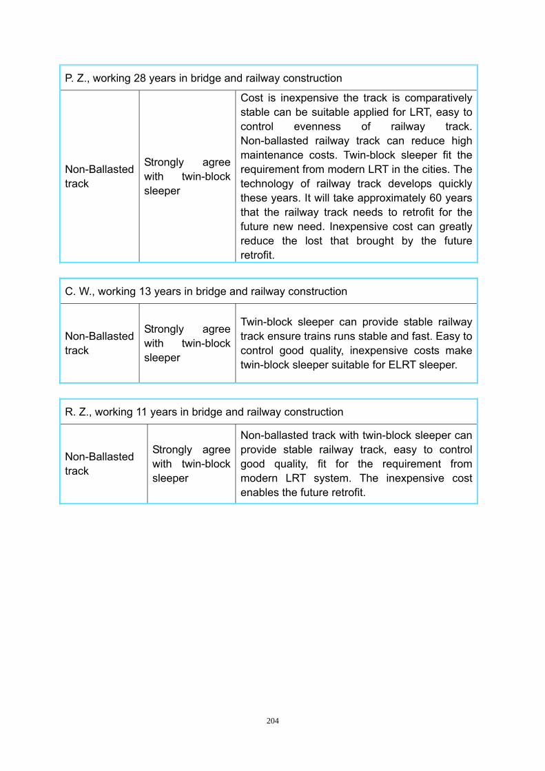
204
P. Z., working 28 years in bridge and railway construction
Non-Ballasted track
Strongly agree with twin-block sleeper
Cost is inexpensive the track is comparatively stable can be suitable applied for LRT, easy to control evenness of railway track. Non-ballasted railway track can reduce high maintenance costs. Twin-block sleeper fit the requirement from modern LRT in the cities. The technology of railway track develops quickly these years. It will take approximately 60 years that the railway track needs to retrofit for the future new need. Inexpensive cost can greatly reduce the lost that brought by the future retrofit.
C. W., working 13 years in bridge and railway construction
Non-Ballasted track
Strongly agree with twin-block sleeper
Twin-block sleeper can provide stable railway track ensure trains runs stable and fast. Easy to control good quality, inexpensive costs make twin-block sleeper suitable for ELRT sleeper.
R. Z., working 11 years in bridge and railway construction
Non-Ballasted track
Strongly agree with twin-block sleeper
Non-ballasted track with twin-block sleeper can provide stable railway track, easy to control good quality, fit for the requirement from modern LRT system. The inexpensive cost enables the future retrofit.


![Material Grado Diccionario Conceptual de Derecho Civil Chileno[1]](https://img.dokumen.tips/doc/110x75/55cf97ee550346d0339484de/material-grado-diccionario-conceptual-de-derecho-civil-chileno1.jpg)


![DICCIONARIO CONCEPTUAL DE DERECHO CIVIL CHILENO[1].pdf](https://img.dokumen.tips/doc/110x75/55cf8ff2550346703ba1960c/diccionario-conceptual-de-derecho-civil-chileno1pdf.jpg)
