Embed Size (px)
Citation preview

Aerodrome Safety Standard Department
1
Verify accuracy and Integrity of Aeronautical Data
2nd Edition, March 2017
CIVIL AVIATION AUTHORITY OF NEPAL
AERODROME SAFETY STANDARD DEPARTMENT
DOCUMENT TO VERIFY ACCURACY AND
INTEGRITY OF DATA PROVIDED BY
AERODROME OPERATOR
Second Edition- March 2017
Civil Aviation Authority of Nepal

Aerodrome Safety Standard Department
2
Verify accuracy and Integrity of Aeronautical Data
2nd Edition, March 2017
AMENDMENTS
After making amendments to this requirement, a record shall be entered in the appropriate
columns below showing amendments number, date, section amended and description of changes,
signatures and entry date.
Note: All pages produced using this requirement will display the date of last amendment, and the
List of Effective Pages will display the amendment status off this page.
Amendment
Number Date Amended
Amended
Part/Section Amended Description
Signature and
Entry Date

Aerodrome Safety Standard Department
3
Verify accuracy and Integrity of Aeronautical Data
2nd Edition, March 2017
TABLE OF CONTENTS
AMENDMENTS .............................................................................................................................. 2
TABLE OF CONTENTS .................................................................................................................. 3
FOREWORD .................................................................................................................................... 6
GLOSSARY OF TERMS ................................................................................................................. 9
CHAPTER ONE: INTRODUCTION ............................................................................................. 27
1.1 Preamble ........................................................................................................................... 27
1.2 Purpose ............................................................................................................................. 28
1.3 Publication ........................................................................................................................ 29
1.4 Requirements for Aerodrome Operators .......................................................................... 30
CHAPTER TWO: DATA ORIGINATION.................................................................................... 31
2.1 Collection of Data ............................................................................................................ 31
2.2 Survey Philosophy............................................................................................................ 38
2.3 Types of Data ................................................................................................................... 39
2.4 Data Management ............................................................................................................ 41

Aerodrome Safety Standard Department
4
Verify accuracy and Integrity of Aeronautical Data
2nd Edition, March 2017
CHAPTER THREE: DATA PROCESSING .................................................................................. 43
2.1 Processing of Data ............................................................................................................ 43
3.2 Submission of Data Information ...................................................................................... 49
3.4 CAAN Aerodrome Data System (CADS) ........................................................................ 56
3.5 Verifying Accuracy .......................................................................................................... 61
3.6 Data Validation & Verification ........................................................................................ 64
3.7 Data Storage ..................................................................................................................... 66
CHAPTER FOUR: QUALITY MANAGEMENT ......................................................................... 67
4.1 Quality Assurance. ........................................................................................................... 67
4.2 Methodology .................................................................................................................... 71
CHAPTER FIVE: PUBLICATION ................................................................................................ 77
5.1 Publication / Presentation ................................................................................................. 77
5.2 Aeronautical Charts. ......................................................................................................... 77
5.3 NOTAM. .......................................................................................................................... 80
5.4 Aeronautical Information Publication (AIP) .................................................................... 83

Aerodrome Safety Standard Department
5
Verify accuracy and Integrity of Aeronautical Data
2nd Edition, March 2017
5.5 Other Publication.............................................................................................................. 90
APPENDIX ..................................................................................................................................... 92

Aerodrome Safety Standard Department
6
Verify accuracy and Integrity of Aeronautical Data
2nd Edition, March 2017
FOREWORD
This document provides the procedure for the collection of aeronautical data through field and
office for the purpose of processing and quality assurance of the data to publish for the purpose of
the safety, regularity and efficiency of international air navigation. It also explains procedure of
submitting data to the Civil Aviation Authority of Nepal (CAAN). The primary purpose of these
general guidelines and specifications is to list the requirements for data collection conducted at
aerodromes through Geographic Information System (GIS) Program. The Aerodrome Safety
Standards Department (ASSD), CAAN administers this program. The procedure covered in this
document provides critical information for the operation and safety of the aircraft operation and
are classified as critical by the International Civil Aviation Organization (ICAO). The role and
importance of aeronautical data changed significantly with the implementation of area navigation
(RNAV), required navigation performance (RNP) and airborne computer based navigation
systems. Corrupt or erroneous aeronautical data can potentially affect the safety of air navigation.
ICAO Annex 15 defines data as critical when “there is a high probability when using corrupted
critical data that the continued safe flight and landing of an aircraft would be severely at risk with
the potential for catastrophe.” The information furnished under these standards covers the entire
spectrum of the aerodrome data requirements, including but not limited to runway and stopway
data, navigational aid data, obstruction data, and data on various aerodrome features, including
taxiways, aprons, and landmark features. Most of this information on source data is acquired by
field survey and/or remote sensing methods.
In developing this guidance material, the CAAN is striving to maximize the level of data collected
while trying to minimize the cost to aerodromes. However, the appropriate collection and safety
implications of the prescribed data against defined, repeatable and verifiable standards far

Aerodrome Safety Standard Department
7
Verify accuracy and Integrity of Aeronautical Data
2nd Edition, March 2017
outweigh the potential costs. The collection and maintenance of the data regarding aerodromes is
a shared responsibility of the CAAN and the Aerodrome operator. The uses of the information
collected according to these standards and specifications are in part to complete the following
tasks:
• Provide geodetic control for engineering projects.
• Assist in aerodrome planning and land use studies.
• Certify aerodromes for certain types of operations (e.g VFR, IFR, Mixed, Precision
approach, etc).
• Develop instrument approach and departure procedures.
• Determine performance of an aircraft.
• Update aeronautical publications.
• Plan for and site navigational aids supporting the aerodrome.
This document provides general specifications, standards, and guidelines for collecting and
maintains the integrity of aerodrome related aeronautical data. These specifications provide the
requirements for capturing the data used in all phases of aerodrome development from planning to
construction, and from origin to its publication in AIP and other official publication. These

Aerodrome Safety Standard Department
8
Verify accuracy and Integrity of Aeronautical Data
2nd Edition, March 2017
specifications are designed to provide information regarding the different types of data collection
tasks on aerodromes.
The CAAN developed these procedures for the purpose of receiving and/or originating,
collating or assembling, editing, formatting, publishing/storing and distributing aeronautical
information/data concerning the entire territory of the Nepal for providing aeronautical services.
Compliance with these requirements and standards without deviation is desirable for all Nepalese
aerodromes.
Director General
Civil Aviation Authority of Nepal

Aerodrome Safety Standard Department
9
Verify accuracy and Integrity of Aeronautical Data
2nd Edition, March 2017
GLOSSARY OF TERMS
Accuracy – A degree of conformance between the estimated or measured value and the true
value.
Note. — For measured positional data, the accuracy is normally expressed in terms of a distance
from a stated position within which there is a defined confidence of the true position falling.
Abeam Point – The point on a line that is nearest to an off line point (for example, a point on the
runway centerline is "abeam" the Glide Slope Antenna when the distance from the centerline
point to the antenna is at a minimum).
Accelerate-Stop Distance Available (ASDA) – The runway plus stopway length declared
available and suitable for the acceleration and deceleration of an airplane aborting a takeoff.
Aerodrome – A defined area on land or water (including any buildings, installations and
equipment) intended to be used either wholly or in part for the arrival, departure and surface
movement of aircraft.
Aerodrome beacon – Aeronautical beacon used to indicate the location of an aerodrome from the
air.
Aerodrome certificate – A certificate issued by the appropriate authority under applicable
regulations for the operation of an aerodrome.
Aerodrome elevation – The elevation of the highest point of the landing area.
Aerodrome mapping data (AMD) – Data collected for the purpose of compiling aerodrome
mapping information for aeronautical uses.

Aerodrome Safety Standard Department
10
Verify accuracy and Integrity of Aeronautical Data
2nd Edition, March 2017
Note. — Aerodrome mapping data are collected for purposes that include the improvement of the
user’s situational awareness, surface navigation operations, training, charting and planning.
Aerodrome mapping database (AMDB) – A collection of aerodrome mapping data organized and
arranged as a structured data set.
Aerodrome reference point (ARP) - The designated geographical location of an aerodrome.
Aeronautical beacon – An aeronautical ground light visible at all azimuths, either continuously or
intermittently, to designate a particular point on the surface of the earth.
Aeronautical Data – A representation of aeronautical facts, concepts or instructions in a
formalised manner suitable for communication, interpretation or processing.
Aeronautical information – Information resulting from the assembly, analysis and formatting of
aeronautical data.
Aeronautical Information Circular (AIC) – A notice containing information that does not
qualify for the origination of a NOTAM or for inclusion in the AIP, but which relates to flight
safety, air navigation, technical, administrative or legislative matters.
Aeronautical Information Publication (AIP) – A publication issued by or with the authority of
a State and containing aeronautical information of a lasting character essential to air navigation.
Aeronautical Information Service (AIS) – A service established within the defined area of
coverage responsible for the provision of aeronautical information/data necessary for the safety,
regularity and efficiency of air navigation.
AIRAC – An acronym (aeronautical information regulation and control) signifying a system
aimed at advance notification based on common effective dates, of circumstances that necessitate
significant changes in operating practices.

Aerodrome Safety Standard Department
11
Verify accuracy and Integrity of Aeronautical Data
2nd Edition, March 2017
Air Navigation Facility – Any facility used in, available for use in, or designed for use in, aid of
air navigation, including landing areas, lights, any apparatus or equipment for disseminating
weather information, for signaling, for radio-directional finding, or for radio or other electrical
communication, and any other structure or mechanism having a similar purpose for guiding or
controlling flight in the air or the landing and takeoff of aircraft.
Aerodrome Lighting – Various lighting aids that may be installed on an aerodrome. Types of
aerodrome lighting include:
• Aerodrome Rotating Beacon (APBN) – A visual navigational aid operated at many
aerodromes. At civil aerodromes, alternating white and green flashes indicate the location of the
aerodrome.
• Approach Light System (ALS) – An aerodrome lighting facility which provides visual
guidance to landing aircraft by radiating light beams in a directional pattern by which the pilot
aligns the aircraft with the extended centerline of the runway on his final approach for landing.
Condenser-Discharge Sequential Flashing Lights/Sequenced Flashing Lights may be installed in
conjunction with the ALS at some aerodromes.
• Precision Approach Path Indicator (PAPI) – A visual approach slope indicator normally
consisting of light units similar to the VASI but in a single row of either two or four light units set
perpendicular to the runway centerline.
• Runway End Identifier Lights (REIL) – Two synchronized flashing lights, one on each side of
the runway threshold, which provide rapid and positive identification of the approach end of a
particular runway.
• Threshold Lights – Fixed green lights arranged symmetrically left and right of the runway
centerline identifying the runway end. When all light units are located outside the runway edge or
runway edge extended, the runway end lights are considered to be “outboard.” If any light unit is
located inside the runway edge or runway edge extended, the lights are considered to be
“inboard.”

Aerodrome Safety Standard Department
12
Verify accuracy and Integrity of Aeronautical Data
2nd Edition, March 2017
Apron – A defined area, on a land aerodrome, intended to accommodate aircraft for purposes of
loading or unloading passengers, mail or cargo, fuelling, parking or maintenance.
Area Navigation – A method of navigation that permits aircraft operation on any desired course
within the coverage of station-referenced navigational signals or within the limits of a self-
contained system capability. Area navigation systems include GPS, Inertial, and LORAN-C.
Assemble – A process of merging data from multiple sources into a database and establishing a
baseline for subsequent processing.
Attributes or Attribute Data – Alphabetical and/or numeric information that describes particular
characteristics of a geospatial feature, such as type, dimensions, usage, occupancy, etc.
Azimuth
• Astronomic Azimuth – At the point of observation, the angle measured from the vertical plane
through the celestial pole and the vertical plane through the observed object. The astronomic
azimuth is established directly from observations on a celestial body and is measured in the plane
of the horizon. Astronomic azimuths differ from geodetic azimuths because of the deflection of
the vertical which can be greater than one minute of arc in extreme cases. Astronomic azimuths
may be reckoned clockwise or counter-clockwise, from either north or south, as established by
convention.
• Geodetic – The angle at point A between the tangent to the meridian at A and the tangent to the
geodesic from A to B whose geodetic azimuth is wanted. It may be reckoned clockwise from
either geodetic north or south as established by convention. Because of earth curvature, the
geodetic azimuth from A to B (forward azimuth) differs from the geodetic azimuth from B to A
(back azimuth) by other than 180 degrees, except where A and B have the same geodetic
longitude or where the geodetic latitude of both points is zero. The “geodesic line” is the shortest
surface distance between two points on the reference ellipsoid. A “geodetic meridian” is a line on
the reference ellipsoid defined by the intersection of the reference ellipsoid and a plane containing
the minor axis of that ellipsoid.

Aerodrome Safety Standard Department
13
Verify accuracy and Integrity of Aeronautical Data
2nd Edition, March 2017
• Grid – The angle in the plane of projection between a straight line and the central meridian of a
plane-rectangular coordinate system. Grid azimuths may be reckoned clockwise from either
geodetic north or south as established by convention.
• Magnetic – At the point of observation, the angle between the vertical plane through the
observed object and the vertical plane in which a freely suspended symmetrically magnetized
needle, influenced by no transient artificial magnetic disturbance, will come to rest. Magnetic
azimuths are reckoned clockwise from magnetic north.
Bench Mark – A relatively permanent natural or artificial material object bearing a marked point
whose elevation above or below an adopted surface (datum) is known.
Clearway – An area beyond the takeoff runway under the control of aerodrome authorities within
which terrain or fixed obstacles may not extend above specified limits. These areas may be
required for certain turbine-powered operations and the size and upward slope of the clearway
will differ depending on when the aircraft was certificated.
Collection – Any combination of data submitted by a provider at a given time.
Cyclic redundancy check (CRC) – A mathematical algorithm applied to the digital expression of
data that provides a level of assurance against loss or alteration of data.
Database – One or more files of data so structured that appropriate applications may draw from
the files and update them.
Data Quality – A degree or level of confidence that the data provided meets the requirements of
the data user in terms of accuracy, resolution, timeliness and integrity.
Datum – Any quantity or set of quantities that may serve as a reference or basis for the
calculation of other quantities

Aerodrome Safety Standard Department
14
Verify accuracy and Integrity of Aeronautical Data
2nd Edition, March 2017
Derived Data – Refers to the data which is derived from other data (entity or derived) and hence,
typically, not related to physical equipment – e.g. an approach procedure derived from runway,
NAVAID and way-point data in association with other factors such as aircraft performance.
Direction Finder (DF) – A radio receiver equipped with a directional sensing antenna used to
take bearings on a radio transmitter.
Distance Measuring Equipment (DME) – Equipment (airborne and ground) used to measure the
slant range distance of an aircraft from the DME navigational aid in nautical miles. DME is
usually frequency paired with other navigational aids such as a VOR or localizer.
Displaced Threshold – A threshold that is located at a point on the runway other than the
designated runway end. The displaced area is available for takeoff or rollout of aircraft, but not
for landing. A displaced threshold does not mark the end of a runway.
Ellipsoid Height – The distance between a point and the reference ellipsoid taken along the
perpendicular to the ellipsoid. Ellipsoid heights are the heights resulting from GPS observations.
Ellipsoid heights are positive if the point is above the ellipsoid. Ellipsoid Height = GEOID Height
+ Orthometric Height.
Feature – A manmade or natural object that appears in the real world such as a building, runway,
navigational aid or river.
Feature Type – A collection of all features of a given type such as all runways or all buildings.
Feature Types are analogous to layers in many GIS applications and are also referred to as Entity
Types and Feature Classes in other standards.
Flight Path – A line, course, or track along which an aircraft is flying or intended to be flown.
Frangible – A type of fixture or fixture mounting designed to break at a predetermined point if
accidentally struck by an aircraft, resulting in minimal damage to the aircraft.

Aerodrome Safety Standard Department
15
Verify accuracy and Integrity of Aeronautical Data
2nd Edition, March 2017
Geodesic distance – The shortest distance between any two points on a mathematically defined
ellipsoidal surface.
Geoid – The equipotential surface in the gravity field of the Earth which coincides with the
undisturbed mean sea level (MSL) extended continuously through the continents.
Note. — The geoid is irregular in shape because of local gravitational disturbances (wind tides,
salinity, current, etc.) and the direction of gravity is perpendicular to the geoid at every point.
Geodetic datum – A minimum set of parameters required to define location and orientation of the
local reference system with respect to the global reference system/frame.
Geoid Height – The distance, taken along a perpendicular to the reference ellipsoid, between the
reference ellipsoid and the Geoid. The Geoid height is positive if the Geoid is above the reference
ellipsoid. Geoid Height = Ellipsoidal Height – Orthometric Height.
Geospatial Data, Geospatially – Referenced Data or Geospatial Vector Data– Data that
identifies the geographic location (2D or 3D coordinates) and characteristics (feature attributes) of
natural or constructed features and boundaries on the earth. This information may be derived from
remote sensing and surveying technologies. The features are represented by a point, line, or
polygon. The position of a point feature is described by a single coordinate pair (or triplet for
three dimensional data). The spatial extent of a line feature is described by a string of coordinates
of points lying along the line, while the extent of a polygon feature is described by treating its
boundary as a line feature. Vector data may be stored in a sequential, a chain node, or a
topological data structure.
Geoid undulation – The distance of the geoid above (positive) or below (negative) the
mathematical reference ellipsoid.
Note.— In respect to the World Geodetic System — 1984 (WGS-84) defined ellipsoid, the
difference between the WGS-84 ellipsoidal height and orthometric height represents WGS-84
geoid undulation.

Aerodrome Safety Standard Department
16
Verify accuracy and Integrity of Aeronautical Data
2nd Edition, March 2017
Global Positioning System (GPS)– A space-based radio-positioning, navigation, and time-
transfer system. The system provides highly accurate position and velocity information and
precise time on a continuous global basis, to an unlimited number of properly equipped users.
Helipad – A small designated area, usually with a prepared surface, on a heliport, aerodrome,
landing/takeoff area, apron/ramp, or movement area used for takeoff, landing, or parking of
helicopters.
Heliport – An aerodrome or a defined area on a structure intended to be used wholly or in part for
the arrival, departure and surface movement of helicopters.
Heliport Reference Point (HRP) – The geographic position of the heliport expressed in latitude
and longitude at (1) the center of the final approach and takeoff (FATO) area or the centroid of
multiple FATOs for heliports having visual and nonprecision instrument approach procedures or
(2) the center of the final approach reference area when the heliport has a precision instrument
approach.
Horizontal Survey Point – A point that represents the horizontal position of a feature. This point
may be located on the feature or located between feature components. For example, the horizontal
survey point for a Precision Approach Path Indicator (PAPI) system is the center of the light array
which falls between light units.
Instrument Landing System (ILS) – A precision instrument approach system which normally
consists of the following electronic components and visual aids: Localizer, Middle Marker, Glide
Slope, Approach Lighting, Outer Marker.
Instrument Runway – A runway equipped with electronic and visual navigational aids for which
a precision or nonprecision approach procedure having straight-in landing minimums have been
approved.
Integrated Aeronautical Information Package – A package which consists of the following
elements:

Aerodrome Safety Standard Department
17
Verify accuracy and Integrity of Aeronautical Data
2nd Edition, March 2017
— AIP, including amendment service;
— Supplements to the AIP;
— NOTAM and PIB;
— AIC; and
— Checklists and lists of valid NOTAM.
Integrity – A degree of assurance that an aeronautical data and its value has not been lost or
altered since the data origination or authorized amendment.
Landing Area – That part of a movement area intended for the landing or take-off of aircraft.
Leveling – The process of determining the difference in elevation between two points. In geodetic
leveling, this process results in a vertical distance from a vertical datum.
• Direct – The determination of differences in elevation by means of a series of horizontal
observations on a graduated rod. The leveling instrument maintains a horizontal line of sight
through spirit leveling or a compensation mechanism. The rod is observed while it is resting on a
point of known elevation (backsight) and then, without disturbing the elevation of the leveling
instrument, is observed a second time while resting on the unknown point (foresight). The
differential in rod readings is applied to the starting elevation to determine the elevation of the
unknown.
• Indirect – The determination of differences in elevation by means other than differential
leveling, such as trigonometric leveling. In trigonometric leveling, the vertical angle and distance
from the instrument to the point of unknown elevation are measured, and the difference in
elevation between the instrument and the unknown point is computed using trigonometry.

Aerodrome Safety Standard Department
18
Verify accuracy and Integrity of Aeronautical Data
2nd Edition, March 2017
Localizer (LOC) – The component of an ILS which provides course guidance to the runway.
Localizer Back Course – The course line defined by the localizer signal along the extended
centerline of the runway in the opposite direction from the normal localizer approach course
(front course.)
Localizer Type Directional Aid (LDA) – A navigational aid used for nonprecision instrument
approaches with utility and accuracy comparable to a localizer but which is not part of a complete
ILS and is not aligned with the runway.
Long Range Navigation (LORAN) – An electronic navigation system by which hyperbolic lines
of position are determined by measuring the difference in the time of reception of synchronized
pulse signals from two fixed transmitters. LORAN A operates in the 1750 - 1950 kHz frequency
band. LORAN C and D operate in the 100 - 110 kHz frequency band.
Marker Beacon – An electronic navigational facility transmitting a 75 MHz vertical fan or bone-
shaped radiation pattern to be received by aircraft flying overhead. Marker beacons are identified
by their modulation frequency and keying code, and when received by compatible airborne
equipment, indicate to the pilot aurally and visually that he is passing over the facility.
• Back Course Marker (BCM) – When installed, normally indicates the localizer back course
final approach fix where approach descent is commenced.
• Inner Marker (IM) – A marker beacon, used with an ILS Category II precision approach,
located between the middle marker and the end of the ILS runway and normally located at the
point of designated decision height (normally 100 feet above the touchdown zone elevation) on
the ILS Category II approach. It also marks progress during a ILS Category III approach.
• Middle Marker (MM) – A marker beacon that defines a point along the glideslope of an ILS,
normally located at or near the point of decision height for ILS Category I approaches.

Aerodrome Safety Standard Department
19
Verify accuracy and Integrity of Aeronautical Data
2nd Edition, March 2017
• Outer Marker (OM) – A marker beacon at or near the glideslope intercepts altitude of an ILS
approach. The outer marker is normally located four to seven miles from the runway threshold on
the extended centerline of the runway.
Mean Sea Level (MSL) – The average location of the interface between the ocean and
atmosphere, over a period of time sufficiently long so that all random and periodic variations of
short duration average to zero.
Metadata – Information about the data itself such as source, accuracy, dates for which the data
are valid, security classification, etc. Metadata is essential in helping users determine the extent on
which they can rely on a given data item to make decisions.
Minimum Safe Altitude Warning (MSAW) – A function of the ARTS III computer that aids the
controller by alerting him when a tracked Mode C equipped aircraft is below or is predicted by the
computer to go below a predetermined minimum safe altitude.
Minimums – Weather condition requirements established for a particular operation or type of
operation; e.g., IFR takeoff or landing, alternate aerodrome for IFR flight plans, VFR flight etc.
Missed Approach – A maneuver conducted by a pilot when an instrument approach cannot be
completed to a landing.
Movement Area – The runways, taxiways, and other areas of an aerodrome/heliport which are
utilized for taxiing/hover taxiing, air taxiing, takeoff, and landing of aircraft, exclusive of loading
ramps and parking areas. At those aerodromes/heliports with a tower, specific approval for entry
onto the movement area must be obtained from ATC.
Navigational Aid (NAVAID) – Any visual or electronic device airborne or on the surface which
provides point-to-point guidance information or position data to aircraft in flight. (Refer to Air
Navigation Facility).

Aerodrome Safety Standard Department
20
Verify accuracy and Integrity of Aeronautical Data
2nd Edition, March 2017
Nondirectional Beacon (NDB) – An L/MF or UHF radio beacon transmitting nondirectional
signals whereby the pilot of an aircraft equipped with direction finding equipment can determine
his bearing to or from the radio beacon and "home" or track to or from the station. When the NDB
is installed in conjunction with an Instrument Landing System marker, it is normally called a
Compass Locator.
Nonprecision Approach Procedure – A standard instrument approach procedure in which no
electronic glide slope is provided; e.g., VOR, TACAN, NDB, LOC, ASR, LDS, and SDF
approaches.
Notice to Airmen (NOTAM) – A notice containing information (not known sufficiently in
advance to publicize by other means) concerning the establishment, condition, or change in any
component (facility, service, or procedure of, or hazard in the National Airspace System) the
timely knowledge of which is essential to personnel concerned with flight operations.
Objective Evidence – The observational and computational data supporting the information
being provided. This evidence is used in the verification process to prove the provided
aeronautical information and substantiate the change being made.
Obstacle – Any object that has a vertical element to it and may or may not penetrate an
obstruction identification surface.
Obstruction – Any object that penetrates an obstruction identification surface.
Obstruction Identification Surface (OIS) – Any imaginary surface authorized by the CAAN to
identify obstructions. Any object that penetrates an OIS is an obstruction.
Offset NAVAID – A NAVAID used during the final approach segment of a straight in instrument
approach and not located on the runway centerline or centerline extended.

Aerodrome Safety Standard Department
21
Verify accuracy and Integrity of Aeronautical Data
2nd Edition, March 2017
Orthometric Height – The distance taken along the plumb line between a point and the Geoid.
Orthometric heights are positive if the point is above the Geoid. Orthometric Height = Ellipsoid
Height – Geoid Height.
Orthophoto – An aerial image that has been taken from above (either from an aircraft or a
satellite) and has been spatially corrected so that features shown on the photo are displayed in
their actual geographic position within a specified range of tolerance.
Photogrammetry – The process of creating vector data such as building outlines and elevation
contours from stereo imagery (pairs of images taken of the same location but at different angles).
Positional Accuracy – The difference between a geospatial feature’s displayed position and its
actual position. Absolute positional accuracy is the difference between a geospatial feature’s
displayed position and its actual position on the face of the earth. Relative positional accuracy is
the difference between a geospatial feature’s displayed position and that of other geospatial
features in the same data set.
Precision – The smallest separation that can be represented by the method employed to make the
positional statement which is the number of units or digits to which a measured or calculated
value is expressed and used
Precision Approach Procedure – A standard instrument approach procedure in which an
electronic glideslope/glidepath is provided; e.g., GPS, ILS, and PAR approaches.
Published Data – Data officially issued for distribution to the public.
Quality- Totality of characteristics of an entity that bear on its ability to satisfy stated and implied
needs.

Aerodrome Safety Standard Department
22
Verify accuracy and Integrity of Aeronautical Data
2nd Edition, March 2017
Quality Assurance – All the planned and systematic activities implemented within the quality
system, and demonstrated as needed, to provide adequate confidence that an entity will fulfil
requirements for quality.
Quality Control – The operational techniques and activities that are used to fulfil requirements
for quality.
Quality level – The extent to which the customer’s needs have been met. A quality level of 100%
means that there has been a complete conformance to specification every time.
Quality Management – All activities of the overall management function that determine the
quality policy, objectives and responsibilities, and implementing them by means such as quality
planning, quality control, quality assurance and quality improvement within the quality system.
Quality Management System – The organisational structure, procedures, processes and
resources needed to implement quality management.
Quality record – Documented evidence of tasks carried out which demonstrates that the required
results have been achieved and provides sufficient links to other quality records to ensure
traceability.
Quality specifications – The minimum, pre-defined specifications that must be met to fulfill the
stated quality requirements. A quality system provides the management control to assure the
required quality specifications are achieved.
Radio Detection and Ranging (RADAR) – A device which provides information on range,
azimuth, and/or elevation of objects in the path of the transmitted pulse by measuring the time
interval between transmission and reception of radio pulses and correlating the angular orientation
of the radiated antenna beam or beams in azimuth and/or elevation.

Aerodrome Safety Standard Department
23
Verify accuracy and Integrity of Aeronautical Data
2nd Edition, March 2017
• Primary Radar – A radar system in which a minute portion of a radio pulse transmitted from a
site is reflected by an object and then received back at the site for processing and display at an air
traffic control facility.
• Secondary radar – A radar system wherein a radio signal transmitted from the radar station
initiates the transmission of a radio signal from another station.
Secondary surveillance radar (SSR) – A surveillance radar system which uses
transmitters/receivers (interrogators) and transponders.
Reference Ellipsoid – A geometric figure comprising one component of a geodetic datum,
usually determined by rotating an ellipse about its shorter (polar) axis, and used as a surface of
reference for geodetic surveys. The reference ellipsoid closely approximates the dimensions of the
Geoid. Certain ellipsoids fit the Geoid more closely for various areas of the earth. Elevations
derived directly from satellite observations are relative to the ellipsoid and are called ellipsoid
heights.
Requirements for quality- Expression of the needs or their translation into a set of quantitatively
or qualitatively stated requirements for the characteristics of an entity to enable its realization and
examination
Resolution – The smallest spacing between two display elements expressed as dots per inch,
pixels per line, or lines per millimeter.
Runway – A defined rectangular area on a land aerodrome prepared for the landing and take-off
of aircraft.
Runway Centerline – A line connecting the two opposite runway end points. The line may be
physically marked on the surface of the runway.
Runway End Point – The point at the runway end halfway between the edges of the runway.

Aerodrome Safety Standard Department
24
Verify accuracy and Integrity of Aeronautical Data
2nd Edition, March 2017
Runway Length – The straight line distance between runway end points. This line does not
account for surface undulations between points. Official runway lengths are normally computed
from runway end coordinates and elevations.
Stopway – A defined rectangular area on the ground at the end of take-off run available prepared
as a suitable area in which an aircraft can be stopped in the case of an abandoned take off.
Take-off Distance Available (TODA) – The length of the take-off run available plus the length
of the clearway, if provided.
Take-off Run Available (TORA) – The length of the runway declared available and suitable for
the ground run of an aeroplane take-off.
Taxiway – A defined path on a land aerodrome established for the taxiing of aircraft and intended
to provide a link between one part of the aerodrome and another, including:
a) Aircraft stand taxilane. A portion of an apron designated as a taxiway and intended to provide
access to aircraft stands only.
b) Apron taxiway. A portion of a taxiway system located on an apron and intended to provide a
through taxi-route across the apron.
c) Rapid exit taxiway. A taxiway connected to a runway at an acute angle and designed to allow
landing aeroplanes to turn off at higher speeds than are achieved on other exit taxiways thereby
minimizing runway occupancy times.
Threshold (THLD) – The beginning of that portion of the runway available for landing. A
displaced threshold is a threshold that is located at a point on the runway other than the designated
beginning of the runway.

Aerodrome Safety Standard Department
25
Verify accuracy and Integrity of Aeronautical Data
2nd Edition, March 2017
Traceability – Ability to trace the history, application or location of an entity by means of
recorded identifications
Traffic Pattern – The traffic flow that is prescribed for aircraft landing at, taxiing on, or taking
off from an aerodrome. The components of a typical traffic pattern are upwind leg, crosswind leg,
downwind leg, base leg, and final approach.
Transmissometer (TMOM) – An apparatus used to determine visibility by measuring the
transmission of light through the atmosphere. It is the measurement source for determining
runway visual range (RVR) and runway visibility value (RVV).
Transponder Landing System (TLS) – Transponder landing system providing azimuth and
elevation guidance to aircraft on approach.
Validation- Confirmation by examination and provision of objective evidence that the particular
requirements for a specific intended use are fulfilled.
Verification- Confirmation by examination and provision of objective evidence that specified
requirements have been fulfilled.
V1 – The takeoff decision speed. If a system failure occurs before V
1, the takeoff is aborted. If the
failure occurs at or above V1, the pilot is committed to continue the takeoff.
Vertical Survey Point – A point that represents the elevation position of a feature. This point
may be located on the top or base of the feature or located between feature components. For
example, the vertical survey point for a Precision Approach Path Indicator (PAPI) system is the
ground at the center of the light array which falls between light units.
Vertical Takeoff and Landing (VTOL) Aircraft – Aircraft capable of vertical climbs and/or
descents and of using very short runways or small areas for takeoff and landings. These aircraft
include, but are not limited to, helicopters.

Aerodrome Safety Standard Department
26
Verify accuracy and Integrity of Aeronautical Data
2nd Edition, March 2017
Very High Frequency Omnidirectional Range Station (VOR) – A ground-based electronic
navigation aid transmitting very high frequency navigation signals, 360 degrees in azimuth,
referenced from magnetic north.
Visual Approach – An approach conducted on an instrument flight rules (IFR) flight plan which
authorizes the pilot to proceed visually to the aerodrome. The pilot must have either the
aerodrome or preceding aircraft in sight at all times.

Aerodrome Safety Standard Department
27
Verify accuracy and Integrity of Aeronautical Data
2nd Edition, March 2017
CHAPTER ONE: INTRODUCTION
1.1 Preamble
This document has been prepared in line with the ICAO Annex 15 (AIS), together with Annexes 4
(Aeronautical Charts), 11 (Air Traffic Services), 14 (Aerodromes) as well as ICAO Documents
9674 (World Geodetic System — 1984 (WGS-84) Manual, 8126 (AIS Manual), 8168 (PANS
OPS) and other supporting materials, to develop and establish a process to ensure that the
aerodrome data, provided by the aerodrome operators for the publication either in the AIP,
NOTAM or other official publication, is verified for its accuracy and integrity by ASSD, CAAN.
It is the quality of the information that made available to end-users (pilots, controllers and their
support systems etc.) which determines the effectiveness of the data-chain in terms of safety,
interoperability and as an enabler for the introduction of new concepts and technologies. There
are various methods that can be used to originate, process, collate, store and distribute
aeronautical information within existing and evolving environments. Thus the first prerequisite is
to ensure that quality data is correctly stipulated and originated, with originators being obliged to
comply with appropriate standards and that their activities are regulated by CAAN. This is
particularly important because the quality of data cannot easily be improved post origination.
Secondly, there are currently many opportunities for aeronautical information to become
corrupted during the data process. This is mainly due to errors introduced at each transaction point
through manual intervention or automated conversion between different data standards/protocols.
Finally, reinforcing the first two points, specific requirements regarding the “quality” of
Aeronautical Data/Information must be applicable on an “end-to-end” basis within the
aeronautical information environment to achieve any meaningful improvement. In order to ensure
the safe operation of the end-user, it is essential that the “quality” of the system as a whole be
ensured. In this context, “quality” should be taken to mean the required accuracy, resolution,

Aerodrome Safety Standard Department
28
Verify accuracy and Integrity of Aeronautical Data
2nd Edition, March 2017
integrity and timeliness of each constituent part of the system. The quality system employed by
CAAN shall provide users with the necessary assurance and confidence that distributed
aeronautical information/data satisfy the stated requirements. In addition, it requires traceability
by the use of appropriate procedures during each stage of data production or data modification
processes.
1.2 Purpose
1.2.1 It was assessed that a major reason for the loss of data integrity was the way in which
aeronautical information was originated, processed, transmitted and delivered from the point of
origination to application in an end-user system. The purpose of this document is to adopt a
process of verification of aerodrome data which will enable Aerodrome Operator to meet their
safety responsibilities and provide the quality data required by the CAAN for following purpose:
Listing of aerodrome data;
Certification of the aerodromes;
Data to be utilize for design and develop flight procedures;
For preparing maps and charts;
For conducting safety evaluations; and
Data to be used for area navigation (RNAV), required navigation performance (RNP) and
airborne computer based navigation systems.

Aerodrome Safety Standard Department
29
Verify accuracy and Integrity of Aeronautical Data
2nd Edition, March 2017
1.2.2 The processed data after verification will be selected for quality assured and then
shall be published in the Aeronautical Information Publication (AIP) and other
associated documents.
1.3 Publication
The publication of aeronautical data shall be published in the following logical steps:
a) Collecting the relevant aerodrome data (data input).
b) Determining the areas of data surveyed (data source).
c) Surveying the areas if required.
d) Listing the Aerodrome Facilities and Master Obstacle data.
e) Updating Aerodrome Manual
f) Producing plans and filtering obstacle data as required.
g) Processing the data report for their accuracy and integrity.
h) Publishing the data and information in official documents.
i) Distributing relevant data and information in the form of published documents.

Aerodrome Safety Standard Department
30
Verify accuracy and Integrity of Aeronautical Data
2nd Edition, March 2017
1.4 Requirements for Aerodrome Operators
1.4.1 This publication will be beneficial for the aerodrome user to develop their confidence due
to level of accuracy of information to reach prescribed safety standards and requirements. CAAN
fully recognizes that each individual aerodrome has its own operational needs and therefore the
data provided should be appropriate and economical to the type of operation intended for its
purpose.
1.4.2 Aerodrome operator shall provide accurate information of their aerodrome and environs
according to the type of operation identified by aerodrome classification issued by CAAN.
Similarly CAAN has issued this document for the purpose of understanding by aerodrome
operator regarding the aeronautical data process considered as "Data Chain" with the following
main stages:
a) Data Requirement
b) Data Origination and Association
c) Data Validation/Verification
d) Data Storage
e) Data Extraction and Compilation
f) Data/Information Promulgation
g) Alternative ‘Delivery’ of Data
h) Data Use

Aerodrome Safety Standard Department
31
Verify accuracy and Integrity of Aeronautical Data
2nd Edition, March 2017
CHAPTER TWO: DATA ORIGINATION
2.1 Collection of Data
The aim of these procedures is to ensure that the aerodrome operator of Nepal should
notify to ASSD, CAAN regarding any changes in the physical condition of the aerodrome due to
accidents, incidents, constructions work, maintenance work, deviation from standards found
during daily inspections and safety related reports from other sources and of new obstacles that
may affect the safety of aircraft operations. The aerodrome operator (General Manager/
Aerodrome Manager) has overall responsibility for ensuring that procedures be established and
resources are provided to report changes to aerodrome physical characteristics, the status of
obstacle limitation surface (OLS), or any other changes that may affect the safety of aircraft
operations.
During the collection of data at an aerodrome if any situation arises, which may have an
immediate effect on the safety of aircraft operations, then it will be reported in the first instance to
ATC by radio or telephone and then confirmation by NOTAM, if applicable, will follow as soon
as possible. In most cases aerodrome conditions or new obstacles that need to be reported
immediately are detected during the daily serviceability inspections. The General
Manager/Aerodrome Manager shall notify the presence of obstacles to ASSD, CAAN with all
data information, and shall control the erection of temporary and permanent structures in the
vicinity of the aerodrome.
The following Chart shows the organization involved in forwarding different aeronautical
data to the end users. It is the responsibility of relevant technical services department of CAAN,
for ensuring the determination of aeronautical raw data which is required for promulgation by the
aeronautical information service (AIS) Nepal. On receipt of the raw data, the relevant technical

Aerodrome Safety Standard Department
32
Verify accuracy and Integrity of Aeronautical Data
2nd Edition, March 2017
services must check, record and edit the data so that they can be released to the next intended user
in a standard format. Raw aeronautical data containing positional information can originate from a
number of different sources as follows:
a) En-route. The surveyed positions of navigational aids and communication facilities
are normally provided by the owner/operator (ATC) of the equipment.
b) SID, STAR, Instrument approach procedures. The calculated positions are normally
determined by the air traffic service provider responsible for the procedure, in
coordination with the technical branch dealing with the procedure design.
c) Aerodrome/heliport. The surveyed positions of thresholds, gates, obstacles and
navigational aids, etc. located at the aerodrome/heliport are normally provided by the
owner or operator of the aerodrome/heliport.
d) Airspace divisions and restrictions. The declared positions are normally defined by
CAAN in coordination of military authorities and other government bodies.
These all data will be forwarded /collected at ASSD, CAAN and then ASSD shall take all
necessary measures to ensure that the aeronautical information/data relating to Aerodromes of
Nepal is adequate, of required quality and timely for further action and processing.
The Organisation Involved

Aerodrome Safety Standard Department
33
Verify accuracy and Integrity of Aeronautical Data
2nd Edition, March 2017
2.1.1 Data Requirement.
The requirement for individual data items may arise for very different reasons, with the majority
of requirements being generated for “traditional” reasons, such as annual (periodic) check surveys
of aerodromes to identify any changes since the previous survey, or the creation of a new/revised
ATS route or instrument procedure. However, requirements may also arise for less prevalent or
unfamiliar reasons, such as the implementation of new concepts or criteria (e.g. WGS 84, RNAV
etc.) or for geo-political (legal) purposes, such as the introduction of special procedures to
safeguard safety and security during regional crises, or for the protection of national interests.

Aerodrome Safety Standard Department
34
Verify accuracy and Integrity of Aeronautical Data
2nd Edition, March 2017
Each individual requirement consists of details regarding the precise facility/location, as well as
requirements for accuracy, resolution and content (e.g. position only, or position and
elevation/height/altitude).
The requirement for data may have arisen, for example, because of the following factors.
• New Facility
• New Technology or Equipment
• New Procedure, Route or Area
• New Obstacle
• New Hazard
• Periodic
• New Concept or Criteria
• Legal
The word new means it also include any revised or removed facilities, services, procedures and
obstructions. Each of above factor may have a number of constituents; some of examples are as
follows:

Aerodrome Safety Standard Department
35
Verify accuracy and Integrity of Aeronautical Data
2nd Edition, March 2017
• New Facility:
o New Aerodrome
o New Runway
o Runway Revision (e.g. Extension or Displaced Threshold)
o New Terminal
o New Taxiway
o Revision of Movement Area
• New Technology or Equipment:
o Microwave Landing System (MLS)
o Differential GPS (DGPS)
o New Surveillance Equipment
o New Precision Approach Equipment
o New Navigation Aid
• New Procedure, Route or Area:
o New Standard Instrument Departure (SID)

Aerodrome Safety Standard Department
36
Verify accuracy and Integrity of Aeronautical Data
2nd Edition, March 2017
o New Standard Instrument Arrival (STAR)
o New Precision Approach Procedure
o New Missed Approach Procedure (MAP)
o New ATS Route
o New Airspace Configuration
• New Obstacle:
o New Building
o New Structure
o Natural Growth of Vegetation
• New Hazard:
o New High Intensity Radio Transmission Area
o New Danger Area
o New Restricted Area
o New Temporary Segregated Airspace (TSA)

Aerodrome Safety Standard Department
37
Verify accuracy and Integrity of Aeronautical Data
2nd Edition, March 2017
o New Activity
• Periodic:
o Periodic requirement to check/update data
• New Concept of Criteria:
o A-SGMCS
o RNAV
o New Geodetic Datum
o New Accuracy/Resolution Requirements
o Dynamic Airspace Management
• Legal:
o Delegation of Airspace/ATS
o Prohibition
o International Treaties and Agreements

Aerodrome Safety Standard Department
38
Verify accuracy and Integrity of Aeronautical Data
2nd Edition, March 2017
2.2 Survey Philosophy
2.2.1 The Data may be “originated” by the Survey and Calculation methods. For Survey
method, this may be achieved by “Traditional” surveying methods using theodolite and
trigonometry and “Modern” surveying methods using GNSS. Similarly for Calculation
method, this may be achieved by “Manual” mathematical calculation and Calculation using
computer based applications.
However, it is likely that not all Data Originators may be familiar with the ATM /
Aerodromes domain requirements and, consequently, may need to be provided with specific
performance requirements and/or guidelines for aeronautical data origination. The World
Geodetic System of 1984 (WGS 84) Manual (Doc 9674) provides some assistance for these
additional specifications and supplemented the requirements of ICAO Annex 15, specifically
elaborating ICAO definitions and specifications to support the specific task of data origination.
2.2.2 The basic survey philosophy applied is to provide master lists of all aerodrome facilities
(i.e. runways, navigation aids, meteorological equipment, etc.) and features identified as
obstacles for each aerodrome. These lists form the basis for all charting, obstacle filtering
(using obstacle identification surfaces) and analysis for Instrument Flight Procedures (IFP)
design.
2.2.3 The challenge placed upon aerodrome operator is to identify appropriate features to survey
in creating these “Master lists”. It will be totally impracticable and costly to survey all
features. Therefore it is important for aerodrome operator to understand the tasks and
challenges faced by the end user, i.e. Aeronautical Charts and Data (ACD) producer, IFP
designers, Aerodrome Inspectors (with regard to Safeguarding), in achieving their
individual objectives.
Aerodrome Safety Standard Department
39
Verify accuracy and Integrity of Aeronautical Data
2nd Edition, March 2017
2.2.4 The aerodrome operator is responsible for providing or arranging for the provision of the
necessary surveyed aerodrome obstacle data to the aeronautical information service (AIS).
The survey should be conducted prior to commissioning any of aerodrome facilities
serving aircraft operation and thereafter at least every five years. The survey specifications
are based on ICAO Annex 4, and are intended to provide detailed data from which
obstacle charts or descriptive text can be derived. Elevations are to be to the nearest foot
and linear dimensions are to be to the nearest half-metre. Co-ordinates are to be expressed
in degrees, minutes, and seconds referenced to the WGS84 datum.
2.2.5 The surveyed data of all aerodrome facilities will be collate or assemble of entire
aerodrome then keep record for further action to check its integrity and verification.
2.3 Types of Data
The following types of data have been listed for the purpose of collecting aeronautical data
by the aerodrome operator from a registered surveyor:
(a) latitude and longitude of the aerodrome reference point in degrees, minutes and
seconds;
(b) runways :—
designation, dimensions and longitudinal slopes of each runway and associated
stopways, clearways, and starter extensions;
elevation above mean sea level (AMSL) of each runway threshold; and
coordinates of each runway threshold;

Aerodrome Safety Standard Department
40
Verify accuracy and Integrity of Aeronautical Data
2nd Edition, March 2017
(c) dimensions of each runway strip and runway end safety area;
(d) depiction of each taxiway and apron area;
(e) coordinates of aircraft stands ;
(f) if available VOR check point radial and distance from the facility;
(g) detail of markings, signs and lighting;
(h) location of meteorological equipment and lighted windsocks;
(i) description of navigational aids; and
(j) location, height (AMSL and AGL) and description of any aerodrome significant
obstacle i.e. any obstacle that intrudes into any of the aerodrome obstacle limitation
surfaces.
(k) description of the :
runway lighting for each runway;
approach lighting for each runway;
visual approach slope indicator system/PAPI including the
glide path angle and threshold crossing height for each
runway;
circling guidance lights, lead in light system, runway end
Aerodrome Safety Standard Department
41
Verify accuracy and Integrity of Aeronautical Data
2nd Edition, March 2017
identification lights, runway alignment indicator lights;
other movement area lighting, taxiway, apron floodlighting,
reflectors;
aerodrome beacon, hazard lights;
lighting controls and limitations of use;
emergency lighting; and
secondary power supply and for which facilities.
2.4 Data Management
2.4.1 Proper data management is crucial during the entire survey and subsequently the recording
process. Aerodrome operators are urged to implement rigorous data handling processes
and practices to eliminate erroneous data submission. Each surveyed entity and associated
attributes shall be dealt with as a single data record stream. Any change to an existing data
record stream identified during a subsequent annual check survey shall necessitate a re-
issue of the entire data record with a new unique record number and the deletion of the old
record number.
2.4.2 If no changes were found to all attributes in an existing record the record shall
retain its original record number and survey date.

Aerodrome Safety Standard Department
42
Verify accuracy and Integrity of Aeronautical Data
2nd Edition, March 2017
2.4.3 If a later full survey is submitted following an initial full survey, all previous data
records shall be declared as obsolete and a new list of survey data records shall be
declared with new record numbers and new survey dates.
2.4.4 These data will be regularly updated for any changes or correctness of its
specification and keep quality assurance by cross checking with daily inspection.
2.4.5 Each supplied data must be checked for the following assurance:
–The data provided meets quality requirements specified by
CAAN.
–The source of any data can be traced in the proper data
record.
–All detected data discrepancies are addressed and reviewed
from the source.
–All reported errors of the data are resolved in a timely manner.
–Delivery of data is made at the agreed time and if the Data is applicable to the
specified intended period, then it should be published.
–Any unresolved errors or anomalies known to remain are made available to the
user.

Aerodrome Safety Standard Department
43
Verify accuracy and Integrity of Aeronautical Data
2nd Edition, March 2017
CHAPTER THREE: DATA PROCESSING
2.1 Processing of Data
The processing of aeronautical data is in transition phase. The introduction of widespread
automation through electronic storage will have more accuracy and free from errors. These
systems will support improvements in the integrity of data, at least at this stage of the process. It
is not known, however, how many of these tools have been validated.
One area of the process phase where it is safe to assume the data obtained “shall, if
possible, be verified before distribution and if not verified shall, when distributed, be clearly
identified as such”. The use of words in this requirement is clear: “if possible”. No mention is
made of cost-effectiveness or practicability. It may be possible to verify the data but, in reality,
AIS providers should have the resources (funding, skills and processes) to do so.
In order to ensure the end-to-end integrity of aeronautical data, it is essential that the data
process is fully identified, mapped and understood. The establishment of this process is critical as
it identifies the key participants, processes, inputs and outputs that must be addressed in any
regularised process. Any process is made up of three key elements; Inputs, Actions and Outputs.
The end-to-end data integrity process is no exception. Data originators (e.g., surveyors, ATS
Personnel, service organisations, etc.) will initiate inputs to the process. The activities that are
then performed in order to turn the inputs into the outputs will form actions associated with the
process. The outputs of the process will be the products that meet the specific need of users for
aeronautical data. These users may be human based or system based. A pilot operating in
accordance with the Visual Flight Rules (VFR) using information derived from an AIP, or a flight
management system (FMS) using its integrated geospatial data, are examples for each type.

Aerodrome Safety Standard Department
44
Verify accuracy and Integrity of Aeronautical Data
2nd Edition, March 2017
The process to ensure Aeronautical Data Integrity has been given in following order.
a. Survey data is provided by ISO9001 accredited companies.
b. Data is stored in electronic media, preferably through use of standard worksheets which
are used throughout the process.
c. In order to ensure that data being transferred electronically is
received at the next activity without having suffered any change, it is necessary that a
CRC value be calculated. This activity is referred to as CRC wrapping.
d. Receiver of data shall conduct a CRC verification to ensure integrity of data (Check
CRC).
e. Data is verified by the ASSD for completeness and quality.
f. Data is transferred electronically to the Publishing Authority (i.e.AIS).
g. AIS shall process the data for storage.
h. AIS shall store the data in database and generate documents for publication when
needed.

Aerodrome Safety Standard Department
45
Verify accuracy and Integrity of Aeronautical Data
2nd Edition, March 2017

Aerodrome Safety Standard Department
46
Verify accuracy and Integrity of Aeronautical Data
2nd Edition, March 2017
The generic Aeronautical Information data process identifies the following main
functional groupings:
a. Surveyors, main organisation for surveying of data;
b. Requesting Authorities – CAAN, Air Navigation Service Provider (ANSP), Air Traffic
Service Provider (ATSP), aerodrome authorities and, possibly, equipment suppliers (such
as those developing terrain awareness warning systems – TAWS) that require surveys of,
and survey information for, aeronautical facilities (navaids, aerodromes, obstacles, etc.);
c. Originating Authorities - organisations responsible for creating facilities related to other
ATM facilities. These organisations may perform procedure or airspace design, airspace
planning etc. and create facilities such as ATS routes or instrument flight procedures;
d. Publishing Authorities – CAAN AIS Department that issue Aeronautical Information.
e. Users – Mostly airlines operators and other associated agencies.
For the purpose of Aeronautical data processing the following model is presented here to
suite the organisational requirement to provide job description according to the processing system
for each technical service departments. (e.g. ASSD processing personals will check for all the
aeronautical data received to provide correct output to the end users.

Aerodrome Safety Standard Department
47
Verify accuracy and Integrity of Aeronautical Data
2nd Edition, March 2017
Data Processing model
3.1.1 Data Recording
Data originated by requesting authorities and originating authorities, surveyors and any
other third party organisations regarding aeronautical data shall be recorded in
ASSD,CAAN.
Those aeronautical data will be collected and recorded from the outcome of following
functions.

Aerodrome Safety Standard Department
48
Verify accuracy and Integrity of Aeronautical Data
2nd Edition, March 2017
3.1.1.1 Surveyed Data:
a. Geodetic datum specification and use;
b. Establishment of Aerodrome survey control networks;
c. Recommended procedures for achieving minimum data
requirements;
d. Monumentation of survey control stations;
e. Production of survey reports;
f. Ongoing maintenance of data;
g. Data management and quality assurance.
3.1.1.2 Calculated and Derived Data (Originating Authority activities):
a. Geodetic datum specification and use;
b. Airspace design;
c. Instrument flight procedure design;
d. Audit;
e. Data management and quality assurance.

Aerodrome Safety Standard Department
49
Verify accuracy and Integrity of Aeronautical Data
2nd Edition, March 2017
3.2 Submission of Data Information
3.2.1 The Processed data for submission to the CAAN shall consist of the following:
• Two electronic copies on CD-ROM to include the Survey Report and
Survey Plans in Adobe PDF format and accompanying Digital Data.
• One original signed copy of completed Survey Data.
3.2.2 The Aerodrome operator shall submit in hard copy the format of the survey
package, comprising report, plans, data and declaration form.
3.2.3 The Aerodrome operator is responsible for ensuring that copies of all survey
information and Survey Data are forwarded within 60 days of the survey date to
ASSD, Civil Aviation Authority of Nepal.
3.2.4 Surveys that fail to conform to the requirements stated in this publication will be
rejected and returned to the Aerodrome operator.
3.3 Listing of Data
3.3.1 Aerodrome geographical and administrative data.
The requirement is for aerodrome geographical and administrative data including:
1) aerodrome reference point (geographical coordinates in degrees, minutes
and seconds) and its site;
2) aerodrome elevation to the nearest metre or foot, and reference
temperature;
3) geoid undulation at the aerodrome elevation position to the nearest metre or
foot;

Aerodrome Safety Standard Department
50
Verify accuracy and Integrity of Aeronautical Data
2nd Edition, March 2017
4) magnetic variation to the nearest degree, date of information and annual
change.
3.3.2 Aprons, taxiways and check locations/positions data.
Details related to the physical characteristics of aprons, taxiways and
locations/positions of designated checkpoints, including:
1) surface ,area and strength of aprons;
2) width, surface and strength of taxiways;
3) location and elevation to the nearest metre or foot of altimeter checkpoints;
4) location of VOR checkpoints
5) position of INS checkpoints in degrees, minutes, seconds and hundredths of
seconds.
3.3.3 Surface movement guidance and control system and markings.
Brief description of the surface movement guidance and control system and
runway and taxiway markings, including:
1) use of aircraft stand identification signs, taxiway guide lines and visual
docking/parking guidance system at aircraft stands;
2) runway and taxiway markings and lights;
3) stop bars (if any).

Aerodrome Safety Standard Department
51
Verify accuracy and Integrity of Aeronautical Data
2nd Edition, March 2017
3.3.4 Aerodrome obstacles.
Detailed description of obstacles, including:
1) obstacles in Area 2
a) obstacle identification or designation;
b) type of obstacle;
c) obstacle position, represented by geographical coordinates in
degrees, minutes, seconds and tenths of seconds;
d) obstacle elevation and height to the nearest metre or foot;
e) obstacle marking, and type and colour of obstacle lighting (if any);
f) if appropriate, an indication that the list of obstacles is available in
electronic form,
2) obstacles in Area 3:
a) obstacle identification or designation;
b) type of obstacle;
c) obstacle position, represented by geographical coordinates in
degrees, minutes, seconds and tenths of seconds;
d) obstacle elevation and height to the nearest metre or foot;
e) obstacle marking, and type and colour of obstacle lighting (if any);

Aerodrome Safety Standard Department
52
Verify accuracy and Integrity of Aeronautical Data
2nd Edition, March 2017
f) if appropriate, an indication that the list of obstacles is available in
electronic form,
Note 1.— description of Area 2 and 3, and graphical illustrations of
obstacle data collection surfaces are given in appendix
Note 2.— Specifications governing the determination and reporting
(accuracy of field work and data integrity) of positions (latitude and
longitude) and elevations for obstacles in Area 2 and 3 are given in
appendix.
3.3.5 Meteorological information provided.
Detail information of meteorological equipment location and their height should
be recorded and provided.
3.3.6 Runway physical Characteristics.
Detailed description of runway physical characteristics, for each runway,
including:
1) designations;
2) true bearings to one-hundredth of a degree;
3) dimensions of runways to the nearest metre or foot;
4) strength of pavement (PCN and associated data) and surface of each runway
and associated stopways;
5) geographical coordinates in degrees, minutes, seconds and hundredths of
seconds for each threshold and runway end, and geoid undulation to the nearest
one-half metre or foot for each threshold;

Aerodrome Safety Standard Department
53
Verify accuracy and Integrity of Aeronautical Data
2nd Edition, March 2017
6) elevations of:
— thresholds of a non-precision approach runway to the nearest metre
or foot; and
— thresholds and the highest elevation of the touchdown zone of a
precision approach runway to the nearest one-half metre or foot;
7) slope of each runway and associated stopways;
8) dimensions of stopway (if any) to the nearest metre or foot;
9) dimensions of clearway (if any) to the nearest metre or foot;
10) dimensions of strips;
11) the existence of an obstacle-free zone.
3.3.7 Declared distances.
Detailed description of declared distances to the nearest metre or foot for each
direction of each runway, including:
1) runway designator;
2) take-off run available;
3) take-off distance available;
4) accelerate-stop distance available;

Aerodrome Safety Standard Department
54
Verify accuracy and Integrity of Aeronautical Data
2nd Edition, March 2017
5) landing distance available; and
If a runway direction cannot be used for take-off or landing, or both, because it is
operationally forbidden, then this must be declared and the words “not usable” or
the abbreviation “NU” entered (Annex 14, Volume I, Attachment A, Section 3).
3.3.8 Approach and runway lighting.
Detailed description of approach and runway lighting, including:
1) runway designator;
2) type, length and intensity of approach lighting system;
3) runway threshold lights, colour and wing bars;
4) type of visual approach slope indicator system;
5) length of runway touchdown zone lights;
6) length, spacing, colour and intensity of runway centre line lights;
7) length, spacing, colour and intensity of runway edge lights;
8) colour of runway end lights and wing bars;
9) length and colour of stopway lights.
3.3.9 Other lighting, secondary power supply.
Aerodrome Safety Standard Department
55
Verify accuracy and Integrity of Aeronautical Data
2nd Edition, March 2017
Description of other lighting and secondary power supply, including:
1) location, characteristics and hours of operation of aerodrome
beacon/identification beacon (if any);
2) location and lighting (if any) of anemometer/landing direction indicator;
3) taxiway edge and taxiway centre line lights;
4) secondary power supply including switch-over time.
3.3.10. Radio navigation and landing aids.
Detailed description of radio navigation and landing aids associated with the
instrument approach and the terminal area procedures at the aerodrome their
location and height of respective equipment as applicable.
3.3.11 Charts related to an aerodrome.
The requirement is for charts related to an aerodrome to be included in the
following order:
1) Aerodrome/Heliport Chart — ICAO;
2) Aircraft Parking/Docking Chart — ICAO;
3) Aerodrome Ground Movement Chart — ICAO;
4) Aerodrome Obstacle Chart — ICAO Type A (for each runway);
5) Precision Approach Terrain Chart — ICAO (precision approach Cat II and
III runways);

Aerodrome Safety Standard Department
56
Verify accuracy and Integrity of Aeronautical Data
2nd Edition, March 2017
6) Area Chart — ICAO (departure and transit routes);
7) Standard Departure Chart — Instrument — ICAO;
8) Area Chart — ICAO (arrival and transit routes);
9) Standard Arrival Chart — Instrument — ICAO;
10) Radar Minimum Altitude Chart — ICAO;
11) Instrument Approach Chart — ICAO (for each runway and procedure
type);
12) Visual Approach Chart — ICAO; and
13) bird concentrations in the vicinity of the aerodrome.
If some of the charts are not produced, a statement to this effect must be provided.
3.4 CAAN Aerodrome Data System (CADS)
For promoting and enhancing aviation safety – data collection, its storage and the
dissemination to the stakeholder and general public is very crucial and important. In this
regard, CAAN Aerodrome Data System (CADS) shall be established, which collects and
process all aerodrome related data. ASSD under the “aerodrome safety data” web based
program collects data from the airports. The data collected from the airports shall be
validated / authenticated by the ASSD and then will be uploaded in the CADS, which is
accessible to authorized ASSD officials only. Following points shall be taken into account
while collecting data from the airports:
1. Data shall be transmitted in an electronic format

Aerodrome Safety Standard Department
57
Verify accuracy and Integrity of Aeronautical Data
2nd Edition, March 2017
2. The airport authority shall make sure, as far as practicable,
to maintain accuracy and authenticity of data updated.
3. The airports updating the data shall first be responsible for
the uploaded data.
4. All the airports shall maintain their own electronic data base.
CAAN shall also have a CAAN DATA Based System (CDBS) which acts as a vital part
of the CAAN overall Management Information System (MIS). The CDBS shall comprise
along with the CADS, other data system such as ATM, AIS, CNS, etc. CAAN after
scrutinizing the data within CDBS, decides on the quality and quantity of data that may be
made public and agreed data will then be published in the AIP under the respective
headings.
Traditional navigation techniques have relied upon the ability to fly to or from point
navigation aids. While the coordinates of the navigation aids have been provided, this
information has not been used as part of the navigation process. Increasing use is being
made of Area Navigation (RNAV) systems which derive the aircraft position from such
sources as Inertial Navigation Systems (INS), Omega, VHF omni-directional radio
range/distance measuring equipment (VOR/DME), dual or multi-DME and Global
Navigation Satellite Systems (GNSS). Based on aeronautical data, RNAV systems
generate appropriate instructions to the autopilots which enable the aircraft to follow the
planned route during the departure, en-route and approach phases and eventually, with the
implementation of GNSS, the landing phases.

Aerodrome Safety Standard Department
58
Verify accuracy and Integrity of Aeronautical Data
2nd Edition, March 2017
Data Integrity
3.4.1 Integrity Requirements.
The integrity of the data can be regarded as the degree of assurance that any data item
retrieved from a storage system has not been corrupted or altered in any way since the
original data entry or its latest authorized amendment. This integrity must be maintained
throughout the data process from survey to data application. In respect to AIS, integrity
must be maintained to the next intended user.
3.4.1.1 Integrity is expressed in terms of the probability that a data item, retrieved from a
storage system with no evidence of corruption, does not hold the same value as intended.

Aerodrome Safety Standard Department
59
Verify accuracy and Integrity of Aeronautical Data
2nd Edition, March 2017
For example, an integrity of 1 × 10⁻⁸ means that an undetected corruption can be expected
in no more than one data item in every 100 000 000 data items processed. Loss of integrity
does not necessarily mean loss of accuracy. However, it does mean that it is no longer
possible to prove that the data are accurate without a further verification of the data from
the point at which integrity can be confirmed.
3.4.1.2 The integrity requirements for data are not absolute. The risk associated with a
point being in error is dependent upon how that data point is being used. Thus the integrity
of a point at threshold, used for landing needs a higher integrity than one, used for en-
route guidance. It is important to note that a lower accuracy does not necessarily imply a
lower integrity requirement.
3.4.1.3 A data item’s use forms the basis for determining its integrity requirement.
Aeronautical data integrity requirements must therefore be based upon the potential risk
resulting from the corruption of data and upon the particular use of the data item.
Consequently, the following classification of data integrity must apply.
a) Critical data. There is a high probability when using corrupted critical data that the
continued safe flight and landing of an aircraft would be severely at risk with the
potential for catastrophe.
b) Essential data. There is a low probability when using corrupted essential data that
the continued safe flight and landing of an aircraft would be severely at risk with the
potential for catastrophe.

Aerodrome Safety Standard Department
60
Verify accuracy and Integrity of Aeronautical Data
2nd Edition, March 2017
c) Routine data. There is a very low probability when using corrupted routine data that
the continued safe flight and landing of an aircraft would be severely at risk with the
potential for catastrophe.
3.4.1.4 To each of these types of data, an integrity level requirement has been assigned as
follows.
a) Critical data: 1 × 10⁻⁸. This level is given to the runway threshold data which
define the landing point. The level of integrity has been derived from the integrity
requirement for autoland and is defined to ensure that the overall process, of which
aeronautical data are only a part, has the required integrity.
b) Essential data: 1 × 10⁻⁵. This level is assigned to points which, while an error can
in itself result in an aircraft being outside of the envelope required, excursion does not
necessarily result in a catastrophe. Examples include en-route navigation aids and
obstacles. The reason why obstacle data can be held with a relatively lower level of
integrity is that, while the data need to be accurate at the time the procedures are
designed, any subsequent corruption should have no impact on the safety of the
aircraft on the condition that it conforms to the procedure requirements.

Aerodrome Safety Standard Department
61
Verify accuracy and Integrity of Aeronautical Data
2nd Edition, March 2017
c) Routine data: 1 × 10⁻³. This level is assigned to data for which errors do not affect
the navigation performance. These include FIR boundary points.
3.4.1.5 The protection of electronic aeronautical data while stored or in transit shall be
totally monitored by the cyclic redundancy check (CRC). To achieve protection of the
integrity level of critical and essential aeronautical data as classified above ASSD, CAAN
shall implement 32-bit or 24-bit CRC algorithm respectively. To achieve protection of the
integrity level, of routine aeronautical data as described above, a 16-bit CRC algorithm
should apply.
3.5 Verifying Accuracy
3.5.1 Accuracy Requirement.
Appropriate survey methods shall be applied to qualify the accuracy and integrity of the
data provided. Survey methodology shall be clearly demonstrated in the Survey Report
and the most stringent survey accuracy shall apply for all the Aerodromes.
The data about aerodromes is critical to the operation and safety and the collection of this
data through a combination of remotely sensed and field survey methods shall be used for
the accuracy. When determining the best method of collection, consider the required
accuracy and efficiency of operations. Remote sensing techniques do not currently meet
the accuracy requirements of some aerodrome and aeronautical features requiring their
collection through field survey. Typically, linear features, some objects within the object
identification surfaces, and visual navigational aids are good candidates for collection by

Aerodrome Safety Standard Department
62
Verify accuracy and Integrity of Aeronautical Data
2nd Edition, March 2017
remote sensing techniques. The geographic coordinate accuracies of this data must meet or
exceed the requirements in the following:
3.5.2. Geodetic Control.
The survey monuments established in the aerodrome vicinity must meet all accuracy
requirements and other criteria specified by CAAN and WGS-84 Manual. These
documents assure accurate relativity between all surveyed points on an aerodrome.
3.5.3. Imagery.
The geo-referenced imagery of the survey area must meet the accuracy requirements
obtained from set procedure approved by DGCA. Due to the critical nature of aerodrome
and aeronautical data, it is important to position and attribute features accurately. Ensure
the spatial resolution and vertex spacing provides an accurate representation of features
without compromising the accuracy of the data. With respect to imagery, this document
defines the word “resolution” as the smallest spacing between two display elements,
expressed as dots per inch, pixels per line, or lines per millimeter. Also consider the
Aerodrome Safety Standard Department
63
Verify accuracy and Integrity of Aeronautical Data
2nd Edition, March 2017
attribute accuracy. Collecting and identifying attributes from imagery requires skill and
knowledge of interpreting aerodrome and aeronautical features. The user must be familiar
with the feature classes, attributes, and valid record entries used to identify spatial features
contained WGS-84 documents.
Features extracted using remote sensing technologies must have spatial accuracies
reported in ground distances at the 95-percent confidence level. Use Root-Mean-Square
Error (RMSE) to estimate spatial accuracies. Testing is the preferred method of reporting
accuracy. Accomplish this by computing RMSE using the square root of the average of the
set of squared differences between twenty or more checkpoint coordinate values and the
coordinate values from an independent source of higher accuracy. However, if less than
twenty checkpoints are available for testing, then report the accuracy as a deductive
estimate based on knowledge of errors in each production step. Indicate in the metadata
the methods used in the deductive method including complete calibration tests and
describe assumptions about error propagation.
3.5.4. Feature Accuracy Requirements.
The accuracy for geospatial vector aerodrome features (taxiway, aprons, ramps, buildings,
etc.) is typically mapping grade accuracy, nominally within 3 feet horizontally and 5 feet
vertically. Specific runway, stopway and navigational aid data accuracies are nominally
within 1 foot horizontal and 0.25 feet vertically. Accuracy requirements for geospatial
features used for geographic orientation (major highways and roads, lakes, rivers,

Aerodrome Safety Standard Department
64
Verify accuracy and Integrity of Aeronautical Data
2nd Edition, March 2017
coastline, and other items of landmark value) are usually 20 feet horizontally and 10 feet
vertically. Derived elevations must be within 10 feet vertically.
3.5.5. Field Surveys.
Many aerodrome features have accuracies greater than are achievable using remotely
sensed methods and require field survey methods be used. These features, specifically the
data for the runway(s) and some navigational aids, are nominally within 1 foot
horizontally and 0.25 feet vertically.
3.6 Data Validation & Verification
As aerodromes move toward a more data centric environment, more information about the
objects on and around the aerodrome is required. Each of these attributes should be
completed. Realizing this will be an iterative process, there are some business rules which
apply to all submissions.
Generally, the surveyor or consultant hired to collect the data will gather some of this
information in the field. Other values can and should be derived from the field
measurements. While other values will require information from other sources such a
record drawings or interviews. Each attribute for each feature should be submitted with the
data. Aerodrome operator should expect surveyors or consultants to complete these
attributes based on the purpose of the survey or data collection effort. Typically any
attribute that can be measured or computed should be completed as part of the statement of
work. Base the requirement for which attributes the consultant should complete on the

Aerodrome Safety Standard Department
65
Verify accuracy and Integrity of Aeronautical Data
2nd Edition, March 2017
intent of the statement of work. If the consultant is hired to collect data for an aerodrome
analysis survey then all attributes relating to those features should be completed.
The more complete the attribution the more complete and useful the data set will be to
both the CAAN and the aerodrome operator in the future. Aerodrome operator should also
plan for the maintenance of this information. If a previously submitted features attribution
changes it should be updated as soon as possible.
Due to the critical nature of some aerodrome features, it is required that the data be
verified and validated by ASSD. The validation/verification could be achieved through
Flight Check, Simulation, Calculation, Photogrammetry and Satellite Imagery.
Typically, these features are those associated with the aerodrome’s movement areas,
navigational systems or those affecting navigable flight such as objects surrounding the
aerodrome. The verification, validation and quality assurance of the safety critical data is
confirmed only after verifying its accuracy of data according to requirements and
standards obtained from set procedures approved by DGCA.
3.6.1. Verification.
In this document, “verification” is defined as the confirmation by examination and
provision of objective evidence that the specified requirements are fulfilled. Verification is
necessary to ensure the data set accurately represents the specifications and is uncorrupted.
The verification process proves the data was properly collected which is obtained from
process approved by DGCA.

Aerodrome Safety Standard Department
66
Verify accuracy and Integrity of Aeronautical Data
2nd Edition, March 2017
3.6.2. Validation.
In this document, “validation” differs from “verification” in scale. The validation
process identifies the aeronautical information submission was correctly developed as an
input to the system. Validation is the confirmation by examination and provisions of
objective evidence showing the data set meets the particular requirements of the intended
use. The purpose of the validation process is to demonstrate the data set has sufficient
overall integrity to satisfy the requirements for its intended application. Validation
answers the questions “is the data reasonable when compared against known data” and
“does it meet the identified need.” Validation does not typically compare the data against
photogrammetric analysis or review of the observational data.
3.7 Data Storage
Validated data should be stored in CAAN Aerodrome Data System Bank with a unique
identifier associated with them; this will allow accurate identification and retrieval of data.
The data during retrieval should provide consistency and plausibility checking for data.
These checks do improvement in data quality and result in the identification of some
potential errors and conflict. The data storing are done as follows:
o Electronic Database
o Paper Documents
o Maps, Charts and Diagrams/Plans

Aerodrome Safety Standard Department
67
Verify accuracy and Integrity of Aeronautical Data
2nd Edition, March 2017
CHAPTER FOUR: QUALITY MANAGEMENT
4.1 Quality Assurance.
Quality system.
The aeronautical data should be organized in such a manner that the quality system is
introduced at all the functional stages of the aeronautical data process, from data
origination to the distribution of data. The quality system should be in conformity with the
International Organization for Standardization (ISO) 9000 series of quality assurance
standards and be certified by Nepalese Government organization. This is done by using a
quality system or quality management system (QMS). The basic elements of such a
system could be:
a) Organization (the management structure). It is very important that the organization be
set up within CAAN with the specified responsibilities for the operation and understood
by all concerned.
b) Planning/procedures. ASSD,CAAN will Identify the tasks to be done and develop
procedures necessary for the production process.
c) Documentation. Procedures should be written down to enable consistency of application
by different personnel. Documents can be updated, but under an authorized control
procedure. Written quality records are needed to provide traceability if there is a problem
to be located.
d) Assessment. The most important part of any quality system is the method of assessment
used, i.e. the audit process. It provides the checks that show whether the procedures are

Aerodrome Safety Standard Department
68
Verify accuracy and Integrity of Aeronautical Data
2nd Edition, March 2017
being used correctly and whether they are achieving the required results. It initiates the
loop to make improvements where necessary. The aim of an assessment is to provide
constructive recommendations for improvement where there are non conformances and to
establish confidence in the methods where there is conformance.
e) Review. The process of considering the assessment result and implementing any
necessary changes through a corrective action procedure.
The following figure shows the basic structure of a quality system which require to be
developed within the organization of ASSD.

Aerodrome Safety Standard Department
69
Verify accuracy and Integrity of Aeronautical Data
2nd Edition, March 2017
4.1.1 ASSD shall take all necessary measures to introduce a properly organized quality
system containing procedures, processes and resources necessary to implement
quality management at each function stage. i.e originate, collate or assemble, edit,
format, publish/store and distribute .The execution of such quality management
shall be made demonstrable for each function stage, when required.
4.1.2 Within the context of a quality system, the skills and knowledge required for each
function shall be identified and personnel assigned to perform those functions shall
be appropriately trained. CAAN shall ensure that personnel possess the skills and
competencies required to perform specific assigned functions, and appropriate

Aerodrome Safety Standard Department
70
Verify accuracy and Integrity of Aeronautical Data
2nd Edition, March 2017
records shall be maintained so that the qualifications of personnel can be
confirmed. Initial and periodic assessments shall be established that require
personnel to demonstrate the required skills and competencies. Periodic
assessments of personnel shall be used as a means to detect and correct shortfalls.
4.1.3 ASSD shall ensure that established procedures exist in order that aeronautical data
at any moment is traceable to its origin so as to allow any data anomalies or errors,
detected during the production/maintenance phases or in operational use, to be
corrected.
4.1.4 The established quality system shall provide users with the necessary assurance
and confidence that distributed aeronautical information/data satisfy stated
requirements for data quality (accuracy, resolution and integrity) and for data
traceability by the use of appropriate procedures in every stage of data production
or data modification process. The system shall also provide assurance of the
applicability period of intended use of aeronautical data as well as that the agreed
distribution dates will be met.
4.1.6 Demonstration of compliance of the quality system applied shall be by audit. If
nonconformity is identified, initiating action to correct its cause shall be
Aerodrome Safety Standard Department
71
Verify accuracy and Integrity of Aeronautical Data
2nd Edition, March 2017
determined and taken. All audit observations and remedial actions shall be
evidenced and properly documented.
4.2 Methodology
4.2.1 WORLD GEODETIC SYSTEM — 1984 (WGS-84)
Introduction.
In order to support implementation of the CNS/ATM systems, CAAN has
implement WGS-84 data and provides geographical coordinates referenced to this
system. A detailed description/list of the WGS-84 coordinate data provided by
CAAN has been published in AIP Nepal.
4.2.2 Requirement of WGS-84.
If a ground-based radar navigation aid is coordinated in two or more different
geodetic reference datums, aircraft horizontal position determination will have two
or more different sets of latitude and longitude values. This could lead to a
situation where an aircraft close to a border between two States with different
geodetic reference datums could be seen by radars in the two States as having
different positions and the potential for misinterpreting aircraft separations and
clearances from restricted areas.The main source of systematic errors is the non-
use of a common geodetic reference datum for determining radar positions; the
solution is to derive the radar positions from a common geodetic reference frame.

Aerodrome Safety Standard Department
72
Verify accuracy and Integrity of Aeronautical Data
2nd Edition, March 2017
There are many geodetic reference datums in use throughout the world providing
references for the charting of particular areas. Each datum has been produced by
fitting a particular mathematical earth model (ellipsoid) to the true shape of the
earth (geoid) in such a way as to minimize the differences between the ellipsoid
and the geoid over the area of interest.
Looking at the current situation, it must be acknowledged that in the en-route
environment, the use of ground-based navigation aids in different reference frames
does not have any significant effect since the primary means of navigation remains
the use of VOR or NDB signals to define radial tracks to or from the beacon with
turning points either at the beacon or at a distance from it, defined by the DME. In
such circumstances, published coordinates of the navigational aid do not affect the
track flown by the aircraft. But this will have big effect either in the approach and
landing phase or where reduced lateral aircraft separation is implemented, i.e. Area
Navigation (RNAV) and Required Navigation Performance (RNP) systems with
higher accuracy and integrity are required. Therefore, these discrepancies will no
longer be tolerable and will demand the introduction of a common geodetic
reference system for use by international civil aviation. The solution to this
problem was to adopt WGS-84 as a common geodetic reference frame for civil
aviation.

Aerodrome Safety Standard Department
73
Verify accuracy and Integrity of Aeronautical Data
2nd Edition, March 2017
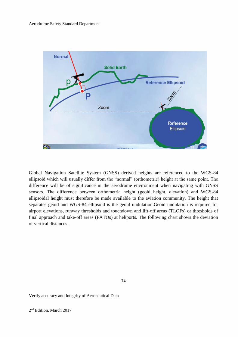
Aerodrome Safety Standard Department
74
Verify accuracy and Integrity of Aeronautical Data
2nd Edition, March 2017
Global Navigation Satellite System (GNSS) derived heights are referenced to the WGS-84
ellipsoid which will usually differ from the “normal” (orthometric) height at the same point. The
difference will be of significance in the aerodrome environment when navigating with GNSS
sensors. The difference between orthometric height (geoid height, elevation) and WGS-84
ellipsoidal height must therefore be made available to the aviation community. The height that
separates geoid and WGS-84 ellipsoid is the geoid undulation.Geoid undulation is required for
airport elevations, runway thresholds and touchdown and lift-off areas (TLOFs) or thresholds of
final approach and take-off areas (FATOs) at heliports. The following chart shows the deviation
of vertical distances.

Aerodrome Safety Standard Department
75
Verify accuracy and Integrity of Aeronautical Data
2nd Edition, March 2017

Aerodrome Safety Standard Department
76
Verify accuracy and Integrity of Aeronautical Data
2nd Edition, March 2017
Thus to fulfill the ICAO requirements for geographical coordinates referenced to the WGS-84
datum at international aerodromes, in flight information regions, enroute and in terminal areas
CAAN should make the necessary arrangements to develop a national WGS-84 implementation
plan and such a plan should contain a timetable for implementation. When developing a national
WGS-84 plan, CAAN should establish a committee composed of personnel from the appropriate
aeronautical and survey departments of Nepal. Such a committee should be tasked with the
management of the WGS-84 implementation plan.
Before the geographical coordinates based on WGS-84 are published in the AIP Nepal and on
charts, every effort must be made to validate and verify them. In order to ensure that quality
(accuracy, resolution and integrity) and traceability requirements for the WGS-84- related
geographical coordinate data are met, the guidance provided in this document should be used for
introducing a quality system programme.
Aerodrome Safety Standard Department
77
Verify accuracy and Integrity of Aeronautical Data
2nd Edition, March 2017
CHAPTER FIVE: PUBLICATION
5.1 Publication / Presentation
Aeronautical information has, until recently, been published only in paper form. However the last
few years have seen the introduction of electronic publications, either electronic representation of
a paper document, such as PDF, or true electronic publications. Although the use of paper remains
the primary means of dissemination, in accordance with the ICAO AIS Manual (Doc 8126), this is
unlikely to remain extant. To achieve this high-level requirement, the publications must be
provided electronically, based on a commonly agreed and standardized data model.
Whilst the move to electronic publication brings benefits to both the service providers and users,
it introduces another area of risk regarding integrity. These risks can be addressed by the same
methods utilised for data transmission. ICAO is currently considering the use of electronic media
as the primary means of providing aeronautical information and it is assumed that electronic
publishing will become the international standard for data dissemination to the users, facilitating
accurate, timely and consistent Aeronautical Information.
The establishment of electronic publication must support the requirement for application of a
standard format assuming, that the information to be published is correct.
5.2 Aeronautical Charts.
5.2.1 The verified and validated data should be published in aeronautical chart of AIP
Nepal at least the following types of charts:

Aerodrome Safety Standard Department
78
Verify accuracy and Integrity of Aeronautical Data
2nd Edition, March 2017
a) Aerodrome Obstacle Chart — ICAO Type A;B;C- These charts are intended to
assist aircraft operators in making the complex take-off mass, distance and
performance calculations required, including those covering emergency
situations such as engine failure during takeoff. Aerodrome obstacle charts
show the runways in plan and profile, take-off flight path areas and the
distances available for take-off run and accelerate-stop, taking obstacles into
account; this data is provided for each runway which has significant obstacles
in the take-off area. The detailed topographical information provided by some
aerodrome obstacle charts includes coverage of areas as far as 45 km away
from the aerodrome itself.
b) Precision Approach Terrain Chart —This chart shall provide detailed terrain
profile information within a defined portion of the final approach so as to
enable aircraft operating agencies to assess the effect of the terrain on decision
height determination by the use of radio altimeters.
c) En-route Chart — This chart shall provide flight crews with information to
facilitate navigation along ATS routes in compliance with air traffic services
procedures.

Aerodrome Safety Standard Department
79
Verify accuracy and Integrity of Aeronautical Data
2nd Edition, March 2017
d) Area Chart -This chart provides pilots with information to facilitate the
transition from en-route phase to final approach phase, as well as from take-off
to en-route phases of the flight. The charts are designed to enable pilots to
comply with departure and arrival procedures and holding pattern procedures;
e) Standard Departure Chart -Instrument (SID) and Standard Arrival Chart -
Instrument (STAR) -When air traffic services routes or position reporting
requirements with sufficient clarity on the area chart cannot be shown then
these separate Charts are produced ;
f) Aerodrome/Heliport Chart –This chart provides an illustration of the
aerodrome or heliport which allows the pilot to recognize significant features,
rapidly clear the runway or heliport touchdown area after landing and follow
taxiing instructions. The charts show aerodrome/heliport movement areas,
visual indicator locations, taxiing guidance aids, aerodrome/heliport lighting,
hangars, terminal buildings and aircraft/heliport stands, various reference
points required for the setting and checking of navigation systems and
operational information such as pavement strengths and radio communication
facility frequencies.;

Aerodrome Safety Standard Department
80
Verify accuracy and Integrity of Aeronautical Data
2nd Edition, March 2017
g) Instrument Approach Chart - This chart provides the pilot with a graphic
presentation of instrument approach procedures, and missed approach
procedures to be followed should the crew be unable to carry out a landing.
This chart type contains a plan and profile view of the approach with full
details of associated radio navigation aids and necessary aerodrome and
topographical information;
h) Visual Approach Chart- This chart illustrates the basic aerodrome layout and
surrounding features easily recognizable from the air. As well as providing
orientation, these charts are designed to highlight potential dangers such as
obstacles, high terrain and areas of hazardous airspace.
i) World Aeronautical Chart — This chart shall provide information to satisfy the
requirements of visual air navigation.
Note.— In the production of Aerodrome Obstacle Charts — ICAO Type A,
Aerodrome Obstacle Charts — ICAO Type C, Instrument Approach Charts —
ICAO, Aerodrome/Heliport Charts — ICAO and Precision Approach Charts —
ICAO, CAAN shall take into account ICAO Annex 4 requirements.
5.3 NOTAM.
International NOTAM offices should be adequately staffed and properly equipped for the
provision of effective 24-hour service. If CAAN is going to establish another International
NOTAM Office beside TIA, CAAN shall define the extent of responsibility and the area
of coverage by each office.

Aerodrome Safety Standard Department
81
Verify accuracy and Integrity of Aeronautical Data
2nd Edition, March 2017
5.3.1 Use and validity of NOTAM
CAAN should ensure that:
a) aeronautical information to be distributed by NOTAM is originated strictly in
accordance with the guidance for the completion of the NOTAM Format
contained in Annex 15;
b) the duration of aeronautical information promulgated by NOTAM does not
exceed three months and if the information is to remain valid after that
period, an appropriate AIP Amendment or Supplement is issued;
c) strict compliance with the requirement to provide at least seven days’
advance notice of the activation of established danger, restricted or prohibited
areas and of activities requiring temporary airspace restrictions, other than for
emergency operations, is observed;
Aerodrome Safety Standard Department
82
Verify accuracy and Integrity of Aeronautical Data
2nd Edition, March 2017
d) a “trigger” NOTAM is originated whenever an AIRAC AIP Amendment or
Supplement is published, giving a brief description of the contents, the
effective date and the reference number of the AIP Amendment or
Supplement. Such a NOTAM must come into force on the same effective
date as the AIP Amendment or Supplement;
e) the monthly printed plain-language summary of NOTAM in force also
contains information on the latest AIP Amendments, AIP Supplements and
AIC issued, and that it is distributed to the recipients with a minimum of
delay by the most expeditious means.
5.3.2 AIS should exercise the proper selectivity in the origination and distribution of
NOTAM by use of the flight information service or, whenever possible, automatic
terminal information service (ATIS), for distribution of information that is valid
for only a few hours.
5.3.3 NOTAM should be mainly used for promulgation of information of a temporary
nature and of short duration. Temporary information promulgated by NOTAM
should not remain in force longer than three months. In exceptional cases, if

Aerodrome Safety Standard Department
83
Verify accuracy and Integrity of Aeronautical Data
2nd Edition, March 2017
temporary information promulgated by NOTAM remains in force for longer than
three months, a replacement NOTAM should be issued.
5.3.4 Use of the abbreviations WIE (“with immediate effect”) and UFN (“until further
notice”) in the NOTAM Format under Items B and C respectively must be avoided
and instead, a ten-figure group giving year, month, day, hours and minutes in UTC
should be used when originating NOTAM. When information on timing is
uncertain, a ten figure date-time group should be followed by an EST to indicate
the approximate duration of information.
5.4 Aeronautical Information Publication (AIP)
The aerodrome data which are relevant to the safe and efficient operation of aircraft at aerodromes
of Nepal must be promulgated in the AIP of Nepal. These data will range from permanent
descriptive material of the aerodrome to information of a short term and temporary nature. The
responsibility for the provision of aerodrome data rests with the Aerodrome Operator.
5.4.1To support the CNS/ATM systems, AIS/MAP should be directed towards the real-
time provision of electronic aeronautical information/data that would ensure
quality and integrity of the information provided. Information contained in the AIP
should be complete and thoroughly checked for correctness before it is provided to
users. To ensure consistency throughout the AIP, changes to the AIP should be
made in such a way that information on the same facility, service, procedure, etc.
affecting one part be changed in the other part(s), if applicable. Strict quality
assurance principles should be put in place in order to ensure that aeronautical data

Aerodrome Safety Standard Department
84
Verify accuracy and Integrity of Aeronautical Data
2nd Edition, March 2017
is of the required quality (accuracy, resolution and integrity), verified and validated
before it is provided to the users. This will give users the required confidence in
the quality of information that is critical to flight safety. The following basic
AIS/MAP requirements should be satisfied regarding:
a) real-time provision and exchange of electronic aeronautical
information/data, through a system that guarantees the quality and integrity
of the information provided;
b) provision and exchange of aeronautical information/data through modern
communications means, including data link, which would allow
interrogation of aeronautical data-bases on the ground from the aircraft;
c) harmonization of AIS and MET information/data to support combined
automated pre-flight and in-flight briefing facilities.
5.4.2 Support for the AIS and MAP services

Aerodrome Safety Standard Department
85
Verify accuracy and Integrity of Aeronautical Data
2nd Edition, March 2017
5.4.2.1 To enable the AIS/MAP to function efficiently and in accordance with
the defined requirements, sufficient funds should be allocated so that all
the administrative and operational requirements of AIS/MAP are met,
including the availability of sufficient and properly qualified personnel
with all the required facilities, equipment and material.
5.4.2.2 The requirements for printing of AIS documentation, including charts
should be ascertained and given the highest priority. Personnel working
for AIS/MAP services should possess the skills and competence
required to perform specific assigned functions. The required skills and
competencies should be demonstrated by AIS and MAP personnel
through initial and periodic assessments on which basis the
corresponding certificate of competence equal to an AIS license may be
accorded.
5.4.3 Coordination between AIS and ASSD.
5.4.3.1 Coordination/liaison on a permanent basis should be established
between AIS/MAP and ASSD for planning and operating aerodrome,
air navigation facilities and services. At least one person from those
services should be assigned and be responsible for maintaining
Aerodrome Safety Standard Department
86
Verify accuracy and Integrity of Aeronautical Data
2nd Edition, March 2017
continuous liaison with AIS/MAP and providing it with “raw”
information as and when required.
5.4.3.2 Aerodromes responsible for origination of the raw aeronautical
information should be acquainted with the requirements for
promulgation and advance notification of changes that are operationally
significant.
5.4.3.3 If the amendment process is too slow for the publication of changes
then the Class II NOTAM should be used to promulgate information.
5.4.3.4 Aerodrome operator should forward any new data, any changes which
affect the accuracy of any published charts or variations of existing data
to ASSD and on checking data it will be forwarded to Aeronautical
Information Service department of CAAN.
5.4.3.5 ASSD personnel should be included in the air navigation planning
processes. This should ensure the timely preparation of appropriate AIS
Aerodrome Safety Standard Department
87
Verify accuracy and Integrity of Aeronautical Data
2nd Edition, March 2017
documentation and that the effective dates for changes to the air
navigation system and procedures are satisfied.
5.4.4 Training of AIS and MAP personnel.
5.4.4.1 Within the context of the quality system implemented, the AIS and
MAP training programme should ensure that AIS and MAP personnel
are appropriately trained according to the skills and competencies
required to perform specific assigned functions.
5.4.4.2 AIS personnel should have, as an essential part of their training,
sufficient knowledge of aeronautical cartography to permit them to
verify information that is published on charts. In addition, AIS
personnel should possess a sufficient background in automation and
knowledge of the English language as are necessary for the
performance of their duties.
5.4.4.3 The aerodrome AIS unit should provide full preflight
Information/briefing service to flight operations personnel and flight

Aerodrome Safety Standard Department
88
Verify accuracy and Integrity of Aeronautical Data
2nd Edition, March 2017
crews for the entire coverage zone. The coverage zone for pre-flight
information service at each aerodrome AIS unit should be determined
taking into account the final destination of aircraft departing from the
aerodrome concerned. This should be done in consultation with aircraft
operators and be reviewed from time to time and/or when the air traffic
pattern is expected to change.
5.4.4.4 Aerodrome AIS units that provide pre-flight information services
should be established at locations conveniently accessible to flight
operations personnel at the aerodromes, preferably on the ground floor
(apron level) of aerodrome terminal buildings.
5.4.4.5 Arrangements should be made between the aerodrome AIS unit, airline
operations personnel (including flight crews) and ATS for an effective
cooperation, coordination and reporting of post-flight information on
inadequacies in the status and operation of air navigation facilities. To
ensure submission of post-flight reports to aerodrome AIS units without
delay, arrangements should be made at aerodrome that a suitable post-
flight report form, such as the one provided in Doc 8126, be made
available to ATS, airline operations offices and aerodrome AIS units.
5.4.4.6 In view of the vital importance of the aeronautical information
contained in the AIP to the safety of air navigation, information in the

Aerodrome Safety Standard Department
89
Verify accuracy and Integrity of Aeronautical Data
2nd Edition, March 2017
AIP should be kept up to date. This should be done by cooperation,
coordination and reporting of information on inadequacies in the status
and operation of air navigation facilities by aerodrome AIS units to
CAAN for publishing in AIP Amendments on specific publication dates
or in accordance with a publication schedule based on regular
intervals.AIP Amendments should be issued at least once every six
months.
5.4.4.7 Data Providers should be provided with basic AIS training so that they
have some understanding of how the data they provide is subsequently
used. This should include the format of data expected by the
applications. The course could also allow methods of error detection to
be covered, with the intention of reducing future problems. The
handling of AIP data within a State could be trained and key processing
issues could be raised and discussed. Data presentation and distribution
for all AIP products could be trained. Every two years or so, refresher
training may be beneficial, to allow the latest procedures followed by
AIS to be reported to the Data Providers.
The training of AIS in surveying may also be considered so that AIS
has an understanding of the process that has to be taken by the
surveyor.

Aerodrome Safety Standard Department
90
Verify accuracy and Integrity of Aeronautical Data
2nd Edition, March 2017
5.5 Other Publication
5.5.1 AIRAC system.
5.5.1.1 CAAN should implement the AIRAC system in accordance with the
requirements of Annex 15 with a minimum of delay and should ensure
that adequate coordination between AIS and other air navigation
services exists to permit effective implementation of the AIRAC
system.
5.5.1.3 Successful implementation of the AIRAC system depends directly on
the level of coordination established among the relevant technical
services and the AIS. To ensure a high level of coordination, CAAN
should prepare their national regulations so that they are well define
the duties and responsibilities of those technical services involved in the
provision of raw AIRAC information to AIS for publication. The
technical services involved should be familiar with the AIRAC system
and comply with it in accordance with specifications provided in
Annexes 11, 14, Volumes I and II, and 15.
5.5.1.4 A schedule of AIRAC publication dates should be issued which
includes a list of latest dates for the receipt of the raw information to be
promulgated by AIRAC, printed on the reverse side of the Aeronautical
Information Promulgation Advice Form.
5.5.1.5 To ensure that aeronautical information of operational significance
reaches users at least 28 days in advance of the AIRAC effective date,
measures should be taken to ensure that:

Aerodrome Safety Standard Department
91
Verify accuracy and Integrity of Aeronautical Data
2nd Edition, March 2017
a) information/data prepared in hard copy format is issued and
distributed at least 56 days prior to the effective date; and
b) information/data provided in electronic format is distributed at
least 35 days in advance of the effective date.
5.5.1.6 Changes to the information promulgated by the AIRAC system should
be avoided by all means, especially during the period consisting of the
first 28 days
5.5.1.7 The AIRAC AIP Amendment shall be used to promulgate operationally
significant changes to the AIP. Where applicable, aeronautical
information of operational significance requiring substantive
amendments to flight documentation (e.g. promulgation of new and/or
revised instrument approach procedures) promulgated by an AIRAC
AIP Supplement should be accompanied by charts or diagrams, as
appropriate, to aid interpretation.
The AIRAC AIP Supplement shall be used to promulgate operationally
significant temporary changes to the AIP.
5.5.1.8 Data Providers should be provided with information of AIRAC dates
and the exact dates by which they should provide data to the AIS in
order to meet these dates, at regular intervals. This could be at six
monthly intervals. It may also be advisable to include a list of AIS
Aerodrome Safety Standard Department
92
Verify accuracy and Integrity of Aeronautical Data
2nd Edition, March 2017
contacts with this to ensure that contact between organisations is as
simple as possible. If a standard form is to be used by the Data
Providers for the submission of data then this could be attached to the
circular.
5.5.2 Aeronautical Information Circulars (AIC).
5.5.2.1 AIS should establish contact with the relevant services providing AIS
with raw aeronautical information to coordinate the preparation and
production of Aeronautical Information Circulars (AIC) strictly in
accordance with Chapter 7 of Annex 15 and Doc 8126.
5.5.2.2 Checklists of current AIC must be issued at least once a year,
irrespective of the number of AIC in force.
APPENDIX
TERRAIN AND OBSTACLE DATA REQUIREMENTS
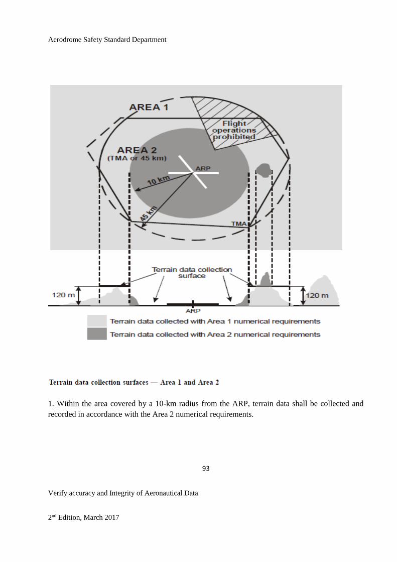
Aerodrome Safety Standard Department
93
Verify accuracy and Integrity of Aeronautical Data
2nd Edition, March 2017
1. Within the area covered by a 10-km radius from the ARP, terrain data shall be collected and
recorded in accordance with the Area 2 numerical requirements.

Aerodrome Safety Standard Department
94
Verify accuracy and Integrity of Aeronautical Data
2nd Edition, March 2017
2. In the area between 10 km and the TMA boundary or 45-km radius (whichever is smaller), data
on terrain that penetrates the horizontal plane
120 m above the lowest runway elevation shall be collected and recorded in accordance with the
Area 2 numerical requirements.
3. In the area between 10 km and the TMA boundary or 45-km radius (whichever is smaller), data
on terrain that does not penetrate the horizontal plane 120 m above the lowest runway elevation
shall be collected and recorded in accordance with the Area 1 numerical requirements.
4. In those portions of Area 2 where flight operations are prohibited due to very high terrain or
other local restrictions and/or regulations, terrain
data shall only be collected and recorded in accordance with the Area 1 numerical requirements.

Aerodrome Safety Standard Department
95
Verify accuracy and Integrity of Aeronautical Data
2nd Edition, March 2017

Aerodrome Safety Standard Department
96
Verify accuracy and Integrity of Aeronautical Data
2nd Edition, March 2017

Aerodrome Safety Standard Department
97
Verify accuracy and Integrity of Aeronautical Data
2nd Edition, March 2017

Aerodrome Safety Standard Department
98
Verify accuracy and Integrity of Aeronautical Data
2nd Edition, March 2017

Aerodrome Safety Standard Department
99
Verify accuracy and Integrity of Aeronautical Data
2nd Edition, March 2017

Aerodrome Safety Standard Department
100
Verify accuracy and Integrity of Aeronautical Data
2nd Edition, March 2017

Aerodrome Safety Standard Department
101
Verify accuracy and Integrity of Aeronautical Data
2nd Edition, March 2017

Aerodrome Safety Standard Department
102
Verify accuracy and Integrity of Aeronautical Data
2nd Edition, March 2017

Aerodrome Safety Standard Department
103
Verify accuracy and Integrity of Aeronautical Data
2nd Edition, March 2017

Aerodrome Safety Standard Department
104
Verify accuracy and Integrity of Aeronautical Data
2nd Edition, March 2017

Aerodrome Safety Standard Department
105
Verify accuracy and Integrity of Aeronautical Data
2nd Edition, March 2017

Aerodrome Safety Standard Department
106
Verify accuracy and Integrity of Aeronautical Data
2nd Edition, March 2017

Aerodrome Safety Standard Department
107
Verify accuracy and Integrity of Aeronautical Data
2nd Edition, March 2017

Aerodrome Safety Standard Department
108
Verify accuracy and Integrity of Aeronautical Data
2nd Edition, March 2017

Aerodrome Safety Standard Department
109
Verify accuracy and Integrity of Aeronautical Data
2nd Edition, March 2017