Embed Size (px)
Citation preview

City, University of London Institutional Repository
Citation: Fu, F. (2010). 3-D nonlinear dynamic progressive collapse analysis of multi-storey steel composite frame buildings—Parametric study. Engineering Structures, 32(12), pp. 3974-3980. doi: 10.1016/j.engstruct.2010.09.008
This is the accepted version of the paper.
This version of the publication may differ from the final published version.
Permanent repository link: http://openaccess.city.ac.uk/6335/
Link to published version: http://dx.doi.org/10.1016/j.engstruct.2010.09.008
Copyright and reuse: City Research Online aims to make research outputs of City, University of London available to a wider audience. Copyright and Moral Rights remain with the author(s) and/or copyright holders. URLs from City Research Online may be freely distributed and linked to.
City Research Online: http://openaccess.city.ac.uk/ [email protected]
City Research Online

1
3-D Nonlinear Dynamic progressive collapse Analysis
of multi-storey steel composite frame buildings –
parametric study
Feng Fu*
School of Engineering, Design and Technology, University of Bradford, Richmond Road,
Bradford, BD71DP
Abstract
A 3-dimensional finite element model built by the author was used in this paper to
analyze the progressive collapse of multi-storey steel composite frame building. The
proposed model can represent the global 3-D behavior of the multi-storey building
under the sudden column removal. Based on this model, parametric studies were
carried out to investigate the structural behavior with variations in: strength of
structural steel, strength of concrete and reinforcement mesh size. Through the
parametric study, the measures to mitigate progressive collapse in the future design
were recommended.
Keywords: progressive collapse, connection, finite element, modelling
* Corresponding author E-mail address: [email protected]

2
1 INTRODUCTION
The terminology of progressive collapse is defined as‘the spread of an initial local
failure from element to element, eventually resulting in the collapse of an entire
structure or a disproportionately large part of it’ [1]. After the event of 11 September
2001, more and more researchers started to refocus on the causes of progressive
collapse in building structures. There are design procedures to mitigate the potential
for progressive collapse in the design guidance of UK and US. In the United States
the Department of Defense (DoD) [2] and the General Services Administration (GSA)
[3] provide detailed information and guidelines regarding methodologies to resist
progressive collapse of building structures. Both employ the alternate path method
(APM). APM is a threat independent methodology, meaning that it does not consider
the type of triggering event, but rather, considers building system response after the
triggering event has destroyed critical structural members. If one component fails,
alternate paths are available for the load and a general collapse does not occur. The
methodology is generally applied in the context of a ‘missing column’ scenario to
assess the potential for progressive collapse and used to check if a building can
successfully absorb loss of a critical member. In U.K., The UK Building Regulations
[4] and BS5950 [5] has led with requirements for the avoidance of disproportionate
collapse. FEMA 2002 [6] and NIST 2005 [7] also provide some general design
recommendations, which require Steel-framed structural systems have enough
redundancy and resilience, such that alternative load paths and additional capacity are
provided for redistributing gravity loads when structural damage occurs. Perimeter
columns and floor framing in particular should have greater mass to enhance thermal and
buckling resistance.
In recent study, there are some experimental and analytical studies on the progressive
collapse behaviors of buildings under the missing column scenario. Khandelwal et al
[8] studied the progressive collapse resistance of seismically designed steel braced
frames with validated two dimensional models. Two types of braced systems are

3
considered: special concentrically braced frames and eccentrically braced frames. The
simulation results show that the eccentrically braced frame is less vulnerable to
progressive collapse than the special concentrically braced frame. Izzuddin et al
[9][10], proposed a simplified framework for progressive collapse assessment of
multi-storey buildings with sudden column loss scenario. It analyzed the nonlinear
static response with dynamic effects evaluated in a simple method. Kim et al [11]
studied the progressive collapse-resisting capacity of steel moment resisting frames
using alternate path methods recommended in the GSA and DoD guidelines. The
linear static and nonlinear dynamic analysis procedures were carried out for
comparison. It was observed that the nonlinear dynamic analysis provided larger
structural responses and the results varied more significantly. However the linear
procedure provided a more conservative decision for progressive collapse potential of
model structures. Paik et al [12] investigated the possibility of progressive collapse of
a cold-formed steel framed structure. The results showed that the removal of corner
wall columns appeared to cause progressive collapse of a portion of the second and
third floor of the end bay directly associated with the column removal, and not the
entire building. Using the commercial program SAP2000, Tsai et al [13] conducted
the progressive collapse analysis following the linear static analysis procedure
recommended by the US General Service Administration GSA .Yu et al [14] proposed
a simplified model to perform progressive collapse analysis, parametric study were
also conducted using their model.
Although there are some research has been done as mentioned above, they all based
on bare steel frames without considering the contribution of the floor systems. Most
of them are 2-D models. Therefore, it is unrelated to real structural performance.
Without considering the contribution of the slabs, the beneficial effects of such as
compressive arching and catenaries actions are not clear. This will lead to the
prediction of an unrealistically large damage area exceeding the prescribed limits.
Therefore, more detailed research on the progressive collapse of multi-storey building
is timely. Using ABAQUS [15], Fu [16] proposed a full scale 3-D finite element

4
model to investigate the progressive collapse of multi-storey building. Research is
conducted in different column removal scenarios. Compared with two dimensional
models, it provides accurate structural behavior of multi-storey buildings under
different sudden columns removal scenarios
In this paper, using the 3-D finite element modeling techniques developed by the Fu
[16], 3-D finite element models representing 20 storey composite steel frame
buildings with bracing system were built to perform the progressive collapse analysis.
Based on these models, parametric studies were carried out to investigate the
structural behaviors of this type of buildings. Through the parametric study, the
measures to mitigate progressive collapse in the future design were also
recommended , which provided important information for additional design guidance
on progressive collapse.
2 3D FINITE ELEMENT MODEL
As shown in Fig 1, a three-dimensional finite element models were created by Fu [16]
using the ABAQUS[15] package to conduct the progressive collapse study of the
high-rise building. The model replicates the 20 storey building with the grid space of
7.5m in both directions as it is shown in Fig 2. The floor height is 3 m for each floor.
The main lateral stability is provided by cross bracing also shown in Fig.1. The slab
thickness are 130mm, the columns are British universal column UC356X406X634
from ground floor to level 6, UC356X406X467 for level 7to level 13,
UC356X406X287 for level 14 to level 19, all the beams are British universal beam
UB305X102X25. The cross bracings are British circular Hollow section CHCF
273X12.5. This model simulated the full structural framing of the typical high-rise
buildings in the current construction industry with full composite action of the
composite slab.

5
2.1 3D finite element Modeling technique
All the beams and columns are simulated using *BEAM elements. The structural
beam elements are modelled close to the centreline of the main beam elements. The
slab are simulated using the four node *Shell element. Reinforcement was represented
in each shell element by defining the area of reinforcement at the appropriate depth of
the cross-section using the *REBAR element from the ABAQUS library. This
reinforcement is defined in both slab directions and was assumed to act as a smeared
layer. The beam and shell elements are coupled together using rigid beam constraint
equations to give the composite action between the beam elements and the concrete
slab. The material properties of all the structural steel components were modelled
using an elastic-plastic material model from ABAQUS [15] which incorporates the
material nonlinearity. The concrete material was modelled using a concrete damage
plasticity model from ABAQUS [15]. The tensile strength of the concrete is ignored
after concrete cracking. The shell elements are integrated at 9 points across the section
to ensure that the concrete cracking behaviour is correctly captured. The models are
supported at the bottom as shown in Fig.1. The mesh representing the model has been
studied and is sufficiently fine in the areas of interest to ensure that the developed
forces can be accurately determined. The steel beam to column connections is
assumed to be fully pinned. The continuity across the connection is maintained by the
composite slab acting across the top of the connection. Therefore, the beam to column
connection is more or less like a semi-rigid composite connection which is to simulate
the characteristic of the connections in normal construction practice. Detailed
modelling techniques were explained in Fu [16].
The columns to be removed are forcibly removed by instantaneously deleting them,
and the subsequent response of each braced frame is then investigated. The maximum
forces, displacements for each of the members involved in the scenario are recorded.
The column is removed over a period of 20 milliseconds with requirement of GSA[3].
The simulations are conducted with 5 % mass proportional damping.

6
2.2 Validation of the model
In order to valid the proposed model, in Fu [16], a two storey composite steel frame
ABAQUS model was built. The model replicated the full scale testing of a
steel-concrete composite frame by Wang et al [17]. Comparison between the tests
result and the modelling result is made. Good agreement is achieved.
3 PARAMETRIC STUDIES
The alternate path method (APM) is applied here to perform the progressive collapse
checking of the existing 20 storey buildings. The resistance ability of the building
under sudden column loss is assessed here using nonlinear dynamic analysis method
with 3-D finite element technique. The loads are computed as dead loads (which is the
self-weight of the floor) plus 25% of the live load in accordance with the acceptance
criteria outlined in Table 2.1 of the GSA guidelines [3]. The columns to be removed
are forcibly removed by instantaneously deleting them. Table 1 shows the list of
analysis cases considered in this study together with the different parameters which
were used in each case. To facilitate the following discussion, the columns and beams
are named as follows according to the grid line shown in Fig2. For instance, Column
C1 stands for the column at the junction of grid C and grid 1. Beam E1-D1 stand for
the beam on grid 1 starting from grid E to grid D.
3.1 Effect of strength of Steel structural member ------ one column removal scenario
In order to evaluate the effect of strength, three grades of steel members are chosen,
which are S275, S355, S460. The comparison is show in Fig.4. It can be seen that,
there is no much difference between these three cases. This is because the inspection
of the model shows that no plastic strain was developed in the steel beams, as is it is
shown in Fig.5. That means all the beams are still in the elastic stage, so no obvious
difference of the response was observed. For the research done so far, most
researchers presume that after one column removed; the plastic hinge will form in the
beam in their analysis model. The modelling result of this paper shows that this is not

7
always true. The plasticity will depend on the size of the beam, the strength of the
beam and the loading. The structure can remains elastic after one column removed.
3.2 Effect of strength of Steel structural member ------ two columns removal scenario
In order to further evaluate the effect of steel strength, two columns removal scenario
was investigated, where, two columns A1 and A2 at ground level were suddenly
removed, as it is shown in Fig.6 that the plastic strain were developed in the steel
beams. The comparison of the response of the models is shown in Fig.7, 8 and 9. It
can be seen that, the lower the steel grade, the larger the maximum vertical dynamic
deflection was observed. It can be also seen that, the higher the steel grade the higher
bending moment and axial force were observed. This is because when plasticity
developed in the steel beam high grade steel exhibits higher yielding and strain
hardening stress, therefore higher bending moment and axial force. From the results,
it can be concluded that, increasing the grade of steel beam will increase the
resistance capacity to progressive collapse as the deflection decreased.
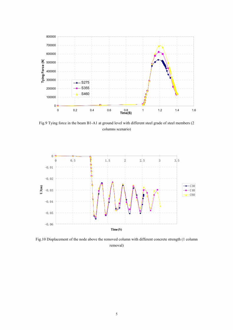
3.3 Effect of concrete strength - one column removal scenario
In order to evaluate the effect of concrete strength, three grades of concrete are chosen,
which are C30, C40, C60. They are the typical concrete grade used in the current
construction practice. The response like vertical displacement, major axis moment and
axial force are reordered. The comparison results are shown in Fig. 10 to 12. When
the columns A1 as shown in Fig. 3 were suddenly removed, the node on the top of the
removed column vibrated and reached a peak vertical displacement and eventually
rest at displacement as shown in Fig. 10. The redistribution of forces was observed to
take place as shown in Fig. 11 and 12. From Fig.10 it can be seen that, the weaker the
concrete strength the greater the maximum vertical dynamic deflection observed. It
can be noticed from the Fig11 and 12 that, the weaker the concrete strength, the
greater the axial force and bending moment were observed in the steel beam, this is

8
because for lower grade concrete strength, the concrete cracked more early than the
higher grade concrete. Therefore, more force is transferred into the steel beams rather
than the slabs.
It can be seen that, Increase the concrete strength will increase the resistance to the
progressive collapse as the deflection reduced and the overall stiffness of the building
is increased. However, the internal force of the steel beam is also increased. It can
also be seen that, the tensile strength of the concrete has smaller effect on response of
the structural. The reason for this is that the joints and the steel beams have provided
sufficient effective tying that prevents large deformation in the floors. This means
increasing of the strength in the concrete has only marginal contribution to the
effective tying of the system. The similar result has been found in the research of [14]
as well.
3.4 Effect of reinforcement mesh - one column removal scenario
In order to evaluate the effect of steel mesh used in the concrete, four types of steel
mesh were chosen first, which are A142, A193, A252 and A393 with mesh size as
142mm2/m, 193mm2/m, 252mm2/m and 393mm2/m respectively. They are the typical
mesh size used in the current composite slab design. The comparison results are
shown in Fig 13, 14 and 15. It can be seen that, when one column A1 was suddenly
removed, the node on the top of the removed column vibrated and substantially
reached a peak vertical displacement. The response eventually rest at displacement as
shown in Fig. 13. A large redistribution of forces was observed to take place as shown
in Fig. 14 and 15. The comparison result shows that, for the conventional steel mesh
used in current construction practice, the variation of the deformation is small. This is
because for these four convention meshes used in the current construction market, the
variation of rebar ratio is small, and force are mainly taken by the steel beams rather
than the slab, as it is discussed in section 3.1. Therefore, the difference is not obvious.
In order to clearly investigate the effect of the steel mesh, more steel meshes are
investigated which are A1930 with mesh size 1930mm2/m and A7200 with mesh size

9
L
i dxEI
MU
0
2
2
ie UU
PU e
7200mm2/m, although these mesh sizes are not actually used in the current
construction market. From Fig.13, It can be seen that, with the increasing of the steel
mesh, lager maximum dynamic deflection is caused. This is because the experiments
done by Fu [18] shows that, with the increasing of the steel bars the rotation capacity
the composite joints increased, therefore larger maximum dynamic deflection is
observed.
From Fig.14 and Fig.15 it can be seen that, the internal force like the beam tying force
and major bending moment increased as well. This is because, after removal, the point
A1 is working as a roller. As the deflection increased, the axial force of the beam
increased due to the increasing of elongation or compression of the beam segment. As
discussed in section 3.1, the beam is still in elastic stage, no plastic hinge is formed,
so from the elastic energy analysis, it can be also seen that:
Where,
Ui is the internal strain energy,
Ue is the potential work due to the loss of the column,
P is the gravity load,
is the deflection.
M is the bending moment of the beam
Therefore, with increasing of deflection, Ue increase, so Ui increased as well,
Therefore M increased. Which means more energy has been transferred into the
system. As no plastic hinge is formed, this amount of energy is stored in the system as
a strain energy, and some are dissipated through the dumping.

10
1)( 2 yy N
N
M
M
3.5 Effect of reinforcement mesh - Three columns removal scenario
In order to clearly investigate the effect of the steel mesh, in this analysis, column A1,
A2 and B1 on the ground level are removed. The steel meshes investigated are A142
with mesh size 142mm2/m, A1420 with mesh size 1420mm2/m and A7200 with mesh
size 7200mm2/m, although the last two mesh sizes are not actually used in the current
construction market.
Plastic strain is also observed similar to two columns removal scenario. From Fig.16,
It can be seen that, with the increasing of the steel mesh, lager maximum dynamic
deflection is observed. From Fig.17 and Fig.18 it can be seen that, with the increasing
of the steel mesh, the beam tying force increase however the major bending moment
decreased. As it is discussed in [19], this is because when plasticity started to develop,
below equation can be obtained:
(1)
Where,
My is the plastic bending moment capacity in the absence of any axial force
Ny is the plastic axial force capacity in the absence of any bending moment.
M is the bending moment and
N is the axial force.
From Eq (1), it can be seen that, when deflection increased due to the increased mesh
size, gravity loads are mainly resisted by the vertical components of axial catenary
forces that develop in the beams. It is apparent from Eq. (1) that, with N approaching
Ny, thus M will approximate to 0. This means that the beam bending stiffness will be
greatly softened by the catenary axial force N. Consequently, when the catenary force
is extremely large, the bending moment will almost disappear, the shape of vertical

11
displacement diagram will approximate to the shape of original bending moment
diagram, and the structure will change from a beam to a cable.
However, the analysis of section 3.4 and 3.5 shows that, the reduction of the M will
not occur in the one column removal scenarios as the structure are still in the elastic
stage, Eq (1) is not applicable, unless large deformation occurs as the three columns
removal scenarios. It normally won’t happen in one or even two columns removal
scenarios, as long as the building is designed in normal grid and the structural
members are designed according to the current code.
3.6 Measures to mitigate progressive collapse
From above parametric study it can be seen that, for the multi-storey composite steel
frame buildings , the way to mitigate the progressive collapse is to increase the
strength of the steel structural members and strength of concrete, however, it only has
marginal effect on the resistance capacity of the building.
It can also be seen that, the building is more vulnerable to the removal of more than
two columns. As it is discussed by Fu [16], this is due to the larger affected loading
area after the column removal which also determines the amount of energy needed to
be absorbed by the remaining building. Therefore, another effective way to resist
progressive collapse is to decrease the spacing of the grid or provide more redundancy
in the structural scheme.
For one column remove scenario, increasing the steel mesh will increase the maximum
dynamic deflection which is a disadvantage. However, for more columns removal
scenarios, because the development of the plasticity, the behaviour of the building
changed. The experiments done by Fu [18] shows that, increasing the steel rebar can
increase the rotation capacity of the composite joint, which allows the plasticisation of
the steel member. Therefore, increase the ductility of the joints. The increasing
ductility increases the energy absorption capacity of the joints. This is because the
ductile joints allow for redistribution of internal forces within the structural system by

12
enabling large deformations so that they are suitable for progressive collapse mitigation
by activating plastic system reserves by transition from flexural loading to tensile load in
the members and joints and initiating of catenary action. So more steel mesh is an
advantage when plasticity developed. However, it is noticed from the analysis of this
paper that, this can only be achieved when more than 1 column are removed, as only large
deflections can make this transfer happen.
4 CONCLUSIONS
In this paper, the behaviour of the 20 storey steel composite frame building under the
sudden column removal was investigated with a 3-D finite element model using
ABAQUS package. Base on this model, parametric studies were carried out to
investigate the structural behaviour with variations in: strength of concrete, strength of
structural steel, reinforcement mesh size. Through the parametric study, the measures
to mitigate progressive collapse design were recommended.
Below are main findings:
1. The risk assessment of multi-storey building shows that, one column removal
scenario is the most frequently occurred scenario. Therefore, most of recent
research is focused on the one column removal of multi-storey buildings. For most
research done so far, the plasticity is presumed to develop in the steel member
under one column removal scenario, and plastic hinge is formed in the beam,
therefore most research are based on the plasticity theory. However, for the beams
size and grid used in the current design practice, this is not always true, after
removal, the beam may still in the elastic stage. The elastic behaviour of the
building after column removal is investigated in this paper in detail.
2. The typical multi-storey building with the cross bracing lateral resistance system
used in the current design practice is less vulnerable to progressive collapse under
the one column removal scenario.

13
3. For one column removal, for the four conventional sizes (A142, A193, A252 and
A393) used in the current composite design practice, the difference mesh size
have slight influence on the behaviour of the structure.
4. For one column removal scenario, increasing the steel mesh will increase the
deflection, due to the increased rotation capacity. As the steel beam are still in the
elastic stage, no plastic hinge are formed, therefore, the catenery effect is not
significant.
5. For more than one column removal scenarios, with the increasing of the steel mesh.
the ductile joint allow for redistribution of internal forces within the structural system
by enabling large deformations so that they are suitable for progressive collapse
mitigation by initiating of catenary action. However, it is noticed from this paper that,
this can only be achieved when more than 1 column are removed as only large
deflections can make this transfer happen.
REFERENCE
[1]ASCE. SEI/ASCE 7-05 Minimum Design Loads for Buildings and Other Structures. Washington, DC: American Society of Civil Engineers; 2005 . [2] Unified Facilities Criteria (UFC)-DoD. Design of Buildings to Resist Progressive Collapse, Department of Defense, 2005. [3] GSA. Progressive collapse analysis and design guidelines for new federal office buildings and major modernization projects. The U.S. General Services Administration; 2003. [4] Office of the Deputy Prime Minister. The building regulations 2000, Part A, Schedule 1: A3, Disproportionate collapse. London (UK); 2004.
[5] British Standards Institution. BS 5950: Structural use of steelwork in buildings, Part 1: Code of practice for design — rolled and welded sections, London (UK); 2001.

14
[6] Federal Emergency Management Agency (FEMA) (2002) FEMA 403, World Trade
Center Building Performance Study: Data Collection, Preliminary Observations, and
Recommendations. Washington, DC, USA, May.
[7] National Institute of Science and Technology (NIST) (2005) Final Report on the Collapse of the World Trade Center Towers. NCSTAR 1, Federal Building and Fire 318 Safety Investigation of the World Trade Center Disaster, US Department of Commerce, Gaithersburg, MD, USA.
[8] Kapil Khandelwal, Sherif El-Tawil, Fahim Sadek, Progressive collapse analysis of seismically designed steel braced frames, Journal of Constructional Steel Research, In Press, Corrected Proof, Available online 8 April 2008
[9] B.A. Izzuddin, A.G. Vlassis, A.Y. Elghazouli, D.A. Nethercot Progressive collapse of multi-storey buildings due to sudden column loss — Part I: Simplified assessment framework, Engineering Structures, Volume 30, Issue 5, May 2008, Pages 1308-1318
[10] A.G. Vlassis, B.A. Izzuddin, A.Y. Elghazouli, D.A. Nethercot Progressive collapse of multi-storey buildings due to sudden column loss—Part II: Application Engineering Structures, Volume 30, Issue 5,May 2008, Pages 1424-1438
[11] Jinkoo Kim, Taewan Kim, Assessment of progressive collapse-resisting capacity of steel moment frames, Journal of Constructional Steel Research,Volume 65, Issue 1, January 2009, Pages 169-179.
[12] Jeom Kee Paik, Bong Ju Kim, Progressive collapse analysis of thin-walled box columns Thin-Walled Structures, Volume 46, Issue 5, May 2008, Pages 541-550
[13] Meng-Hao Tsai, Bing-Hui Lin, Investigation of progressive collapse resistance and inelastic response for an earthquake-resistant RC building subjected to column failure. Engineering Structures,In Press, Corrected Proof, Available online 21 July 2008
[14]Min Yu, Xiaoxiong Zha,, Jianqiao Ye, The influence of joints and composite floor slabs on effective tying of steel Journal of Constructional Steel Research, Volume 66, Issue 3, March 2010, Pages 442-451

15
[15] ABAQUS theory manual, (2003) Version 6.7 Hibbitt, Karlsson and Sorensen, Inc. Pawtucket, R.I.
[16] Feng Fu, Progressive collapse analysis of high-rise building with 3-D finite element modelling method, Journal of Constructional Steel Research, Vol. 65,2009, pp1269-1278
[17]Jing-Feng Wang, Guo-Qiang Li Testing of semi-rigid steel–concrete composite frames subjected to vertical loads, Engineering Structures, Volume 29, Issue 8, August 2007, Pages 1903-1916.
[18] F. Fu and D. Lam, (2006) ‘Experimental study on semi-rigid composite joints with steel beams and precast hollowcore slabs’, Journal of Constructional Steel Research, Vol.62, No. 8, pp 771-782.
[19] J.L. Liu, ‘Preventing progressive collapse through strengthening beam-to-column
connection, Part 1: Theoretical analysis’, Journal of Constructional Steel Research 66 (2010) 229_237.

1
FIGURES
Fig 1 Analysis model with braces as lateral bracing
Fig 2 Typical plan layout of the ETABS model

2
Fig .3 Acceleration contour of model under one column removal scenario
Fig.4 Displacement of the node above the removed column with different steel grade of steel members
-0.06
-0.05
-0.04
-0.03
-0.02
-0.01
0
0 0.5 1 1.5 2 2.5 3 3.5Time(s)
U3
(m)
S275
S355
S460

3
Fig.5 Axial Plastic strain of beam B1-A1 at ground level for case with S355 strength (1 column
removal)
Fig.6 Axial Plastic strain of beam B1-A1 at ground level for case with S355 strength (2 columns
removal)
-0.0002
-0.00015
-0.0001
-0.00005
0
0 0.5 1 1.5
Time(s)
Pla
stic
str
ain

4
Fig.7 Displacement of the node at A1 with different steel grade of steel members (2 columns scenario)
Fig.8 Major Moment of at B1 in Beam B1-A1 at ground level with different steel grade for steel
member (2 columns scenario)
-0.14
-0.12
-0.1
-0.08
-0.06
-0.04
-0.02
0
0 0.2 0.4 0.6 0.8 1 1.2 1.4 1.6
Time(S)
U3
(m)
S275
S355
S460
0
10000
20000
30000
40000
50000
60000
70000
80000
0 0.2 0.4 0.6 0.8 1 1.2 1.4 1.6Time(S)
Mo
men
t(N
.m))
S275
S355
S460
5
Fig.9 Tying force in the beam B1-A1 at ground level with different steel grade of steel members (2
columns scenario)
Fig.10 Displacement of the node above the removed column with different concrete strength (1 column
removal)
0
100000
200000
300000
400000
500000
600000
700000
800000
0 0.2 0.4 0.6 0.8 1 1.2 1.4 1.6Time(S)
Ty
ing
Fo
rce
(N
)
S275
S355
S460
-0.06
-0.05
-0.04
-0.03
-0.02
-0.01
0
0 0.5 1 1.5 2 2.5 3 3.5
Time(S)
U3(
m) C30
C40
C60

6
Fig.11 Major Moment of At end B1 of Beam A1-B1 at ground level with different concrete strength (1
column removal)
Fig.12 Tying force Beam of A1-B1 at ground level with different concrete strength (1 column removal)
0
5000
10000
15000
20000
25000
30000
35000
40000
0 0.5 1 1.5 2 2.5 3 3.5
Time(s)
Ben
din
g M
om
ent(
N.m
)
C30
C40
C60
0
50000
100000
150000
200000
250000
300000
350000
400000
450000
0 0.5 1 1.5 2 2.5 3 3.5
Time(s)
Tyi
ng
Fo
rce
(N)
C30
C40
C60

7
Fig. 13 Displacement of the node above the removed column with different mesh (1 column removal)
Fig.14 Axial force of At B1 of Beam A1-B1 at ground level with different mesh (1 column removal)

8
Fig.15 Major Moment at B1 of Beam A1-B1 at ground level with different mesh (1 column removal)
Fig. 16 Displacement of the node above the removed column with different mesh (3 columns removal)
Fig.17 Axial force of At C1 of Beam B1-C1 at ground level with different mesh (3 columns removal)

9
Fig.18 Major Moment at At C1 of Beam B1-C1 at ground level with different mesh (3 columns
removal)