Embed Size (px)
Citation preview

DEVELOPMENT REVIEW HEARING
Meeting Date: October 21, 2020
File No.(s): PLN2020-14492 Location: 756 Baird Avenue, a 6,100 square-foot site, located on the east side
of Baird Avenue, approximately 120 feet south of Clyde Avenue; APN: 101-23-022; property is zoned Single-Family Residential (R1-6L).
Applicant: Natalia Amatuni for Residential Design Owner: Venu Thiruvengada Request: Architectural Review of a 276 square-foot first-floor expansion and
756 square-foot second-story addition to an existing 1,778 square-foot three-bedroom and two-bathroom home, resulting in a 2,810 square- foot, six-bedroom and four-bathroom home including a 426 square-foot two-car garage to remain.
Mailing Radius: 300 feet CEQA Determination: Categorical Exemption per CEQA 15301(e)(1), Existing Facilities Project Planner: Jeff Schwilk, Associate Planner Staff Recommendation: Approve, subject to conditions
Project Data
Lot Size: 6,100 sq. ft.
Existing Floor Area (sq. ft.)
Proposed Addition (sq. ft.)
Proposed Floor Area (sq.ft.)
First Floor 1,352 276 1,778 Second Floor n/a 756 756 Porch covers n/a 25 25
Garage 426 426 Sheds 120 120
Gross Floor Area 1,778 2,960 Lot Coverage 1,898/6,100 = 31% 2,349/6,100 = 38%
F.A.R. 1,778/6,100 = .29 2,960/6,100 = .49 % of 2nd floor to 1st floor n/a 756/2,229 = 34%
Bedrooms/Baths 3/2 3/2 6/4 Flood Zone X X
Points for consideration • The existing house was constructed in 1964 and located in the Bonnie Brae Tract. • The house is bordered on all sides by similar existing single-story homes. • The project includes the construction of a 276 square foot ground floor addition to the front of the
existing house, and a 756 square foot second-floor addition above the rear ground floor area of the existing house.
• The project would increase the living area of the existing house by expanding the living room and kitchen areas to the front ground floor of the house and a new second floor addition with three new bedrooms and two bathrooms upstairs.
• The exterior of the addition would be clad in metal tile roofing to match the existing house roof, as well as stucco siding and vinyl windows to match the exterior materials of the existing house.
AGENDA ITEM #: 7.B PROJECT OVERVIEW
City of Santa Clara The Center of What's Possible

Development Review Hearing Address: 756 Baird Avenue October 21, 2020 Page 2
• Overall proposed building height is 22-feet, 6-inches, including 8-foot ceiling heights for the first and second floors.
• The proposal includes the addition of a 3-foot deep by 11-foot wide balcony off the south wall of the second-floor master bedroom.
• 300-foot neighborhood notice was distributed for this project review. • There are no active code enforcement cases for this property.
Findings supporting the Staff Recommendation
1) That any off-street parking area, screening strips and other facilitates and improvements
necessary to secure the purpose and intent of this title and the general plan of the City area a part of the proposed development, in that;
• The proposal provides the required two covered parking spaces. • The required parking spaces are not located in the required front yard or side yard
landscaped areas. • The proposed project provides areas surfaced with all-weather materials for parking of
vehicles.
2) That the design and location of the proposed development and its relation to neighboring developments and traffic is such that it will not impair the desirability of investment or occupation in the neighborhood, will not unreasonably interfere with the use and enjoyment of neighboring developments, and will not create traffic congestion or hazard, in that;
• The proposed house expansion resulting in three additional bedrooms and two additional bathrooms would not create traffic congestion or hazards.
• Public streets are adequate in size and design to serve the proposed single-family residence, and the use will not create a substantive increase in traffic.
3) That the design and location of the proposed development is such that it is in keeping with the
character of the neighborhood and is such as not to be detrimental to the harmonious development contemplated by this title and the general plan of the City, in that;
• The proposed development is a two-story home that is consistent with the scale and design similar to the existing surrounding neighborhood.
4) That the granting of such approval will not, under the circumstances of the particular case,
materially affect adversely the health, comfort or general welfare of persons residing or working in the neighborhood of said development, and will not be materially detrimental to the public welfare or injuries to property or improvements in said neighborhood, in that;
• The project is subject to the California Building Code and City Code requirements, which serve to regulate new construction to protect public health, safety and general welfare.
5) That the proposed development, as set forth in the plans and drawings, are consistent with the
set of more detailed policies and criteria for architectural review as approved and updated from time to time by the City Council, which set shall be maintained in the planning division office. The policies and criteria so approved shall be fully effective and operative to the same extent as if written into and made a part of this title, in that;
• The project would create a house design that is compatible scale and character with the housing types that is consistent with the neighborhood.

Development Review Hearing Address: 756 Baird Avenue October 21, 2020 Page 3
Conditions of Approval: 1) Garage shall be maintained clear and free for vehicle parking use at all times. It shall not be
used only for storage.2) Submit plans for final architectural review to the Planning Division and obtain architectural
approval prior to issuance of building permits. Said plans to include, but not be limited to:site plans, floor plans, elevations, landscaping, lighting and signage.
3) Landscaping installation shall meet City water conservation criteria in a manner acceptableto the Director of Community Development.
4) Maintain the front yard landscaping between the house and sidewalk. New landscape areasof 500 square feet or more or rehabilitated landscape areas of 2,500 square feet or moreshall conform to the California Department of Water Resources Water Efficient LandscapeOrdinance.
5) The applicant shall plant and maintain a street tree in the front yard.6) Developer/Owner is responsible for collection and pick-up of all trash and debris on-site and
adjacent public right-of-way.7) Construction activity shall be limited to the hours of 7:00 a.m. to 6:00 p.m. weekdays and
9:00 a.m. to 6:00 p.m. Saturdays for projects within 300 feet of a residential use and shall notbe allowed on recognized State and Federal holidays.
8) Incorporate Best Management Practices (BMPs) into construction plans and incorporate postconstruction water runoff measures into project plans in accordance with the City’s UrbanRunoff Pollution Prevention Program standards prior to the issuance of permits.
Attachments 1) Development Plans
GSPublisherEngine 0.0.100.100
GSPublisherEngine 0.0.100.100
OF
SHEET NUMBER
DATE
PROJECT NO.
REVISIONS
BY
NAT
ALIA
AM
ATU
NI
RES
IDEN
TIAL
DES
IGN
n.am
atun
i@gm
ail.c
om40
8 4
2004
11
PRO
JECT
FOR
Ven
u Th
iruv
enga
da75
6 BAIR
D A
VE,
SAN
TA C
LARA
, CA,
9505
4
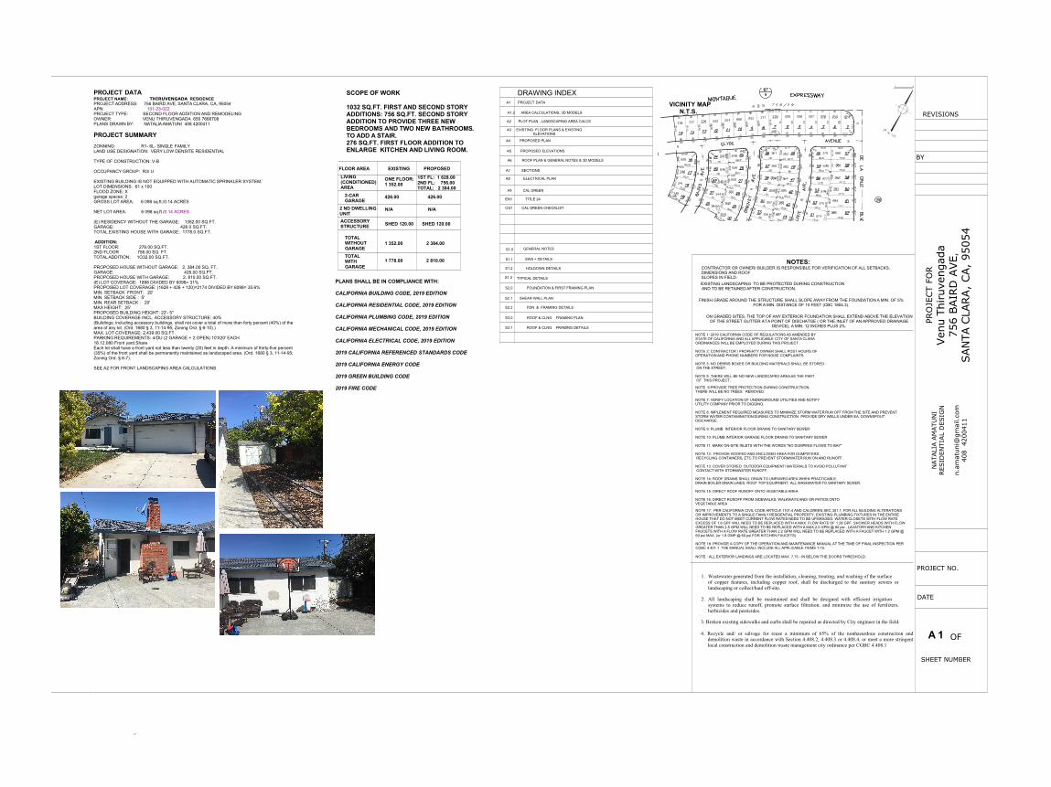
A 1
PROJECT DATAPROJECT NAME: THIRUVENGADA RESIDENCEPROJECT ADDRESS: 756 BAIRD AVE, SANTA CLARA, CA, 95054APN: 101-23-022PROJECT TYPE: SECOND FLOOR ADDITION AND REMODELINGOWNER: VENU THIRUVENGADA 650 7666708PLANS DRAWN BY: NATALIA AMATUNI 408 4200411
PROJECT SUMMARYZONNING: R1- 6L- SINGLE FAMILYLAND USE DESIGNATION: VERY LOW DENSITE RESIDENTIAL
TYPE OF CONSTRUCTION: V-B
OCCUPANCY GROUP: R3/ U
EXISTING BUILDING IS NOT EQUIPPED WITH AUTOMATIC SPRINKLER SYSTEM.LOT DIMENSIONS: 61 x 100FLOOD ZONE: Xgarage spaces: 2GROSS LOT AREA: 6 098 sq.ft./0.14 ACRES
NET LOT AREA: 6 098 sq.ft./0.14 ACRES
(E) RESIDENCY WITHOUT THE GARAGE: 1352.00 SQ.FT.GARAGE: 426.0 SQ.FT.TOTAL EXISTING HOUSE WITH GARAGE: 1778.0 SQ.FT.
ADDITION:1ST FLOOR: 276.00 SQ.FT.2ND FLOOR 756.00 SQ. FT.TOTAL ADDITION: 1O32.00 SQ.FT.
PROPOSED HOUSE WITHOUT GARAGE: 2, 384.00 SQ. FT.GARAGE: 426.00 SQ.FT.PROPOSED HOUSE WITH GARAGE: 2, 810.00 SQ.FT.(E) LOT COVERAGE: 1898 DIVIDED BY 6098= 31%PROPOSED LOT COVERAGE: (1628 + 426 + 120)=2174 DIVIDED BY 6098= 35.6%MIN. SETBACK FRONT: 20'MIN. SETBACK SIDE : 5'MIN. REAR SETBACK : 20'MAX HEIGHT: 25'PROPOSED BUILDING HEIGHT: 22'- 5"BUILDING COVERAGE INCL. ACCESSORY STRUCTURE: 40%(Buildings, including accessory buildings, shall not cover a total of more than forty percent (40%) of thearea of any lot. (Ord. 1680 § 3, 11-14-95; Zoning Ord. § 6-10).)MAX. LOT COVERAGE: 2,439.00 SQ.FT.PARKING REQUIREMENTS: 4/DU (2 GARAGE + 2 OPEN) 10'X20' EACH18.12.080 Front yard.ShareEach lot shall have a front yard not less than twenty (20) feet in depth. A minimum of thirty-five percent(35%) of the front yard shall be permanently maintained as landscaped area. (Ord. 1680 § 3, 11-14-95;Zoning Ord. § 6-7).
SEE A2 FOR FRONT LANDSCAPING AREA CALCULATIONS
VICINITY MAP N.T.S.
A6 ROOF PLAN & GENERAL NOTES & 3D MODELS
A7 SECTIONS
A1 PROJECT DATA
S1.0
S1.1
S1.2 HOLDOWN DETAILS
S1.3
S2.0 FOUNDATION & FIRST FRAMING PLAN
A3 EXISTING FLOOR PLANS & EXISTINGELEVATIONS
A4 PROPOSED PLAN
A8 ELECTRICAL PLAN
GENERAL NOTES
TYPICAL DETAILS
S2.1 SHEAR-WALL PLAN
S2.2 FDN & FRAMING DETAILS
S3.0 ROOF & CLNG FRAMING PLAN
SWS + DETAILS
S3.1 ROOF & CLNG FRAMING DETAILS
EN1 TITLE 24
CG1 CAL GREEN CHECKLIST
DRAWING INDEX
A2 PLOT PLAN , LANDSCAPING AREA CALCS
A5 PROPOSED ELEVATIONS
FLOOR AREA EXISTING PROPOSED
ONE FLOOR:1 352.00
1ST FL: 1 628.002ND FL: 756.00TOTAL: 2 384.00
2-CARGARAGE
426.00 426.00
2 ND DWELLINGUNIT
N/A N/A
ACCESSORYSTRUCTURE SHED 120.00
TOTALWITHOUTGARAGE
NOTES:CONTRACTOR OR OWNER/ BUILDER IS RESPONSIBLE FOR VERIFICATION OF ALL SETBACKS,DIMENSIONS AND ROOFSLOPES IN FIELD.EXISTING LANDSCAPING TO BE PROTECTED DURING CONSTRUCTION AND TO BE RETAINED AFTER CONSTRUCTION.
NOTE 6:PROVIDE TREE PROTECTION DURING CONSTRUCTIION.THERE WILL BE NO TREES REMOVED.
NOTE 7: VERIFY LOCATION OF UNDERGROUND UTILITIES AND NOTIFYUTILITY COMPANY PRIOR TO DIGGING.
NOTE 8: IMPLEMENT REQUIRED MEASURES TO MINIMIZE STORM WATER RUN OFF FROM THE SITE AND PREVENTSTORM WATER CONTAMINATION DURING CONSTRUCTION PROVIDE DRY WELLS UNDER EA. DOWNSPOUTDISCHARGE.
FINISH GRADE AROUND THE STRUCTURE SHALL SLOPE AWAY FROM THE FOUNDATION A MIN. OF 5%FOR A MIN. DISTANCE OF 10 FEET (CBC 1804.3).
ON GRADED SITES, THE TOP OF ANY EXTERIOR FOUNDATION SHALL EXTEND ABOVE THE ELEVATIONOF THE STREET GUTTER AT A POINT OF DISCHATGE ( OR THE INLET OF AN APPROVED DRAINAGE
DEVICE), A MIN. 12 INCHES PLUS 2%.
NOTE 1: 2019 CALIFORNIA CODE OF REGULATIONS AS AMENDED BYSTATE OF CALIFORNIA AND ALL APPLICABLE CITY OF SANTA CLARAORDINANCES WILL BE EMPLOYED DURING THIS PROJECT.
NOTE 2: CONTRACTOR / PROPERTY OWNER SHALL POST HOURS OFOPERATION AND PHONE NUMBERS FOR NOISE COMPLAINTS.
NOTE 3: NO DEBRIS BOXES OR BUILDING MATERIALS SHALL BE STORED ON THE STREET.
NOTE 5: THERE WILL BE NO NEW LANDSCAPED AREA AS THE PART OF THIS PROJECT.
3. Broken existing sidewalks and curbs shall be repaired as directed by City engineer in the field.
4. Recycle and/ or salvage for reuse a minimum of 65% of the nonhazardous construction anddemolition waste in accordance with Section 4.408.2, 4.408.3 or 4.408.4, or meet a more stringentlocal construction and demolition waste management city ordinance per CGBC 4.408.1
1. Wastewater generated from the installation, cleaning, treating, and washing of the surfaceof copper features, including copper roof, shall be discharged to the sanitary sewers orlandscaping or collect/haul off-site.
2. All landscaping shall be maintained and shall be designed with efficient irrigationsystems to reduce runoff, promote surface filtration, and minimize the use of fertilizers,herbicides and pesticides.
NOTE 9: PLUMB INTERIOR FLOOR DRAINS TO SANITARY SEWER
NOTE 10: PLUMB INTERIOR GARAGE FLOOR DRAINS TO SANITARY SEWER
NOTE 11: MARK ON-SITE INLETS WITH THE WORDS "NO DUMPING! FLOWS TO BAY"
NOTE 12: PROVIDE ROOFED AND ENCLOSED AREA FOR DUMPSTERS , RECYCLING CONTAINERS, ETC.TO PREVENT STORMWATER RUN ON AND RUNOFF.
NOTE 13: COVER STORED OUTDOOR EQUIPMENT/ MATERIALS TO AVOID POLLUTANT CONTACT WITH STORMWATER RUNOFF.
NOTE 14: ROOF DRAINS SHALL DRAIN TO UNPAWED AREA WHEN PRACTICABLE.DRAIN BOILER DRAIN LINES, ROOF TOP EQUIPMENT, ALL WASHWATER TO SANITARY SEWER.
NOTE 15: DIRECT ROOF RUNOFF ONTO VEGETABLE AREA
NOTE 16: DIRECT RUNOFF FROM SIDEWALKS, WALKWAYS AND/ OR PATIOS ONTOVEGETABLE AREA
NOTE 17: PER CALIFORNIA CIVIL CODE ARTICLE 1101.4 AND CALGREEN SEC 301.1, FOR ALL BUILDING ALTERATIONSOR IMPROVEMENTS TO A SINGLE FAMILY RESIDENTIAL PROPERTY, EXISTING PLUMBING FIXTURES IN THE ENTIREHOUSE THAT DO NOT MEET CURRENT FLOW RATES NEED TO BE UPGRAGEG. WATER CLOSETS WITH FLOW RATEEXCESS OF 1.6 GPF WILL NEED TO BE REPLACED WITH A MAX. FLOW RATE OF 1.28 GPF. SHOWER HEADS WITH FLOWGREATER THAN 2.5 GPM WILL NEED TO BE REPLACED WITH A MAX.2.0 GPM @ 80 psi . LAVATORY AND KITCHENFAUCETS WITH A FLOW RATE GREATER THAN 2.2 GPM WILL NEED TO BE REPLACED WITH A FAUCET WITH 1.2 GPM @60 psi MAX. (or 1.8 GMP @ 60 psi FOR KITCHEN FAUCETS).
NOTE 18: PROVIDE A COPY OF THE OPERATION AND MAINTENANCE MANUAL AT THE TIME OF FINAL INSPECTION PERCGBC 4.401.1 THE MANUAL SHALL INCLUDE ALL APPLICABLE ITEMS 1-10.
NOTE : ALL EXTERIOR LANDINGS ARE LOCATED MAX. 7.75 - IN BELOW THE DOORS THRESHOLD.
A9 CAL GREEN
SCOPE OF WORK
1032 SQ.FT. FIRST AND SECOND STORYADDITIONS: 756 SQ.FT. SECOND STORYADDITION TO PROVIDE THREE NEWBEDROOMS AND TWO NEW BATHROOMS.TO ADD A STAIR.276 SQ.FT. FIRST FLOOR ADDITION TOENLARGE KITCHEN AND LIVING ROOM.
PLANS SHALL BE IN COMPLIANCE WITH:
CALIFORNIA BUILDING CODE, 2019 EDITION
CALIFORNIA RESIDENTIAL CODE, 2019 EDITION
CALIFORNIA PLUMBING CODE, 2019 EDITION
CALIFORNIA MECHANICAL CODE, 2019 EDITION
CALIFORNIA ELECTRICAL CODE, 2019 EDITION
2019 CALIFORNIA REFERENCED STANDARDS CODE
2019 CALIFORNIA ENERGY CODE
2019 GREEN BUILDING CODE
2019 FIRE CODE
LIVING(CONDITIONED)AREA
1 352.00 2 384.00
SHED 120.00
A1.2 AREA CALCULATIONS, 3D MODELS
TOTALWITHGARAGE
1 778.00 2 810.00
MONTAGUE EXPRESSWAY

GSPublisherEngine 0.0.100.100
GSPublisherEngine 0.0.100.100
OF
SHEET NUMBER
DATE
PROJECT NO.
REVISIONS
BY
NAT
ALIA
AM
ATU
NI
RES
IDEN
TIAL
DES
IGN
n.am
atun
i@gm
ail.c
om40
8 4
2004
11
PRO
JECT
FOR
Ven
u Th
iruv
enga
da75
6 BAIR
D A
VE,
SAN
TA C
LARA
, CA,
9505
4
588.05 sq ft
525.24 sq ft
230.42 sq ft
426.43 sq ft
8.65 sq ft
24'-11"
23'-9
"
23'-9
"
26'-6"
11'-6
"8'
-8 1
/2"
22'-2
"
19'-3"
EXISTING HOUSE FLOORAREA CALCULATIONS
A
HOUSEwithoutgarage:
B
C
D
E
TOTAL EXISTING HOUSEWITHOUT GARAGE: 1 352.00 SQ.FT.
GARAGE: 426.00 SQ.FT.TOTAL EXISTING HOUSE WITH GARAGE:
1 778.0 SQ.FT.
garage
A
C
D
B
E
588.05 sq ft
525.24 sq ft
230.42 sq ft
8.65 sq ft
426.43 sq ft
1, 352.00
245.05 sq ft
298.55 sq ft
156.69 sq ft
111.48 sq ft101.40 sq ft
11'-6
"
22'-1"
9'-1
1"12
'11
'-1"
24'-11"
10'-2 1/2" 12'-6" 13'-8"
.
.
PROPOSED HOUSE FLOORAREA CALCULATIONS
F
G
H I
J
A
1ST Flwithoutgarage
B
C
D
E
TOTAL EXISTING HOUSEWITHOUT GARAGE: 1 352.00 SQ.FT.
GARAGE: 426.00 SQ.FT.TOTAL EXISTING HOUSE WITH GARAGE:
1 778.0 SQ.FT.PROPOSED TWO-STORY HOUSE:
1ST. FLOOR: 1 628 SQ.FT.2ND. FLOOR: 756.00 SQ.FT.
LIVING/ CONDITIONED AREA: 2 384.00 SQ.FT.GARAGE: 426.00 SQ.FT.
PROPOSED HOUSE TOTAL: 2 810.00 SQ.FT.
garage
588.05 sq ft
525.24 sq ft
230.42 sq ft
8.65 sq ft
426.43 sq ft
1, 627.87
F
G
H
I
2ND FL 756.48 sq.ft.
J 152.14 sq ft1ST Fladdition
K1ST Fladdition 123.37 sq ft
245.05 sq ft
298.55 sq ft
101.40 sq ft
111.48 sq ft
588.05 sq ft
525.24 sq ft
230.42 sq ft
426.43 sq ft
8.65 sq ft
123.37 sq ft
24'-11"
23'-9
"
23'-9
"11
'-6"
8'-8
1/2
"
22'-2
"
19'-3"
8'-7
"
14'-5" 12'-1 1/2"
12'-6
1/2
"
152.14 sq ft
A
C
D
B
E
JK
AREA CALCULATIONS
EXISTING HOUSE1/4"=1'0"
PROPOSED SECOND FLOOR AREA1/4"=1'0"
276 SQ.FT. ADDED THE FIRST FLOOR3D MODELSFRONT LEFT
PROPOSED FIRST FLOOR AREA1/8"=1'0"
REAR
RIGHT
➔
~

GSPublisherEngine 0.0.100.100
GSPublisherEngine 0.0.100.100
OF
SHEET NUMBER
DATE
PROJECT NO.
REVISIONS
BY
NAT
ALIA
AM
ATU
NI
RES
IDEN
TIAL
DES
IGN
n.am
atun
i@gm
ail.c
om40
8 4
2004
11
PRO
JECT
FOR
Ven
u Th
iruv
enga
da75
6 BAIR
D A
VE,
SAN
TA C
LARA
, CA,
9505
4
Preventing Pollution: It’s Up to Us In the Santa Clara Valley, storm drains transport water directly to local creeks and San Francisco Bay without treatment. Stormwater pollution is a serious problem for wildlife dependent on our waterways and for the people who live near polluted streams or baylands. Some common sources of this pollution include spilled oil, fuel, and fluids from vehicles and heavy equipment; construction debris; sediment created by erosion, landscaping runoff containing pesticides or weed killers; and materials such as used motor oil, antifreeze, and paint products that people pour or spill into a street or storm drain. Thirteen valley municipalities have joined together with Santa Clara County and the Santa Clara Valley Water District to educate local residents and businesses and fight stormwater pollution. Join us, by following the practices described in this pamphlet. Doing the Job Right General Business Practices
Schedule excavation and grading work during dry weather.
Perform major equipment repairs away from the
job site.
When refueling or vehicle/equipment maintenance must be done on site, designate a location away from storm drains.
Do not use diesel oil to lubricate equipment
parts, or clean equipment.
Practices During Construction Remove existing vegetation only when
absolutely necessary. Plant temporary vegetation for erosion control on slopes or where construction is not immediately planned.
Protect downslope drainage courses, streams, and storm drains with wattles, or temporary drainage swales. Use check dams or ditches to divert runoff around excavations. Refer to the Regional Water Quality Control Board’s Erosion and Sediment Control Field Manual for proper erosion and sediment control measures.
Cover stockpiles and excavated soil with secured tarps or plastic sheeting.
Dewatering Operations Storm Drain Pollution
from Earth-Moving Activities and Dewatering
Soil excavation and grading operations loosen large amounts of soil that can flow or blow into storm drains when handled improperly. Sediments in runoff can clog storm drains, smother aquatic life, and destroy habitats in creeks and the Bay. Effective erosion control practices reduce the amount of runoff crossing a site and slow the flow with check dams or roughened ground surfaces.
Contaminated groundwater is a common problem in the Santa Clara Valley. Depending on soil types and site history, groundwater pumped from construction sites may be contaminated with toxics (such as oil or solvents) or laden with sediments. Any of these pollutants can harm wildlife in creeks or the Bay, or interfere with wastewater treatment plant operation.
1. Check for Toxic Pollutants
Check for odors, discoloration, or an oily sheen on groundwater.
Call your local wastewater treatment agency and ask whether the groundwater must be tested.
If contamination is suspected, have the water tested by a certified laboratory.
Depending on the test results, you may be allowed to discharge pumped groundwater to the storm drain (if no sediments present) or sanitary sewer. OR, you may be required to collect and haul pumped groundwater offsite for treatment and disposal at an appropriate treatment facility.
2. Check for Sediment Levels
If the water is clear, the pumping time is less than 24 hours, and the flow rate is less than 20 gallons per minute, you may pump water to the street or storm drain.
If the pumping time is more than 24 hours and the flow rate greater than 20 gpm, call your local wastewater treatment plant for guidance.
If the water is not clear, solids must be filtered or settled out by pumping to a settling tank prior to discharge. Options for filtering include: Pumping through a perforated pipe sunk
part way into a small pit filled with gravel; −
−
−
Pumping from a bucket placed below water level using a submersible pump; Pumping through a filtering device such as a swimming pool filter or filter fabric wrapped around end of suction pipe.
When discharging to a storm drain, protect the inlet using a barrier of burlap bags filled with drain rock, or cover inlet with filter fabric anchored under the grate. OR pump water through a grassy swale prior to discharge.
Small Business Hazardous Waste Disposal Program
Discharging sediment-laden water from a dewatering site into any water of the state without treatment is prohibited.
Storm Drain Pollution from Fresh Concrete and
Mortar Applications
Preventing Pollution: It’s Up to Us In the Santa Clara Valley, storm drains transport water directly to local creeks and San Francisco Bay without treatment. Stormwater pollution is a serious problem for wildlife dependent on our creeks and bays and for the people who live near polluted streams or baylands. Common sources of this pollution include spilled oil, fuel, and fluids from vehicles and heavy equipment; construction debris; sediment created by erosion; landscaping runoff containing pesticides or weed killers; and materials such as used motor oil, antifreeze, and paint products that people pour or spill into a street or storm drain. Thirteen valley municipalities have joined together with Santa Clara County and the Santa Clara Valley Water District to educate local residents and businesses and fight stormwater pollution. Join us, by following the practices described in this pamphlet.
Doing the Job Right General Business Practices
Wash out concrete mixers only in designated wash-out areas in your yard, away from storm drains and waterways, where the water will flow into a temporary waste pit in a dirt area. Let water percolate through soil and dispose of settled, hardened concrete as garbage. Whenever possible, recycle washout by pumping back into mixers for reuse.
Wash out chutes onto dirt areas at site that do not flow to streets or drains.
Always store both dry and wet materials under cover, protected from rainfall and runoff and away from storm drains or waterways. Protect dry materials from wind.
Secure bags of cement after they are open. Be sure to keep wind-blown cement powder away from streets, gutters, storm drains, rainfall, and runoff.
Do not use diesel fuel as a lubricant on concrete forms, tools, or trailers.
During Construction
Don’t mix up more fresh concrete or cement than you will use in a two-hour period.
Set up and operate small mixers on tarps or heavy plastic drop cloths.
When cleaning up after driveway or sidewalk construction, wash fines onto dirt areas, not down the driveway or into the street or storm drain.
Protect applications of fresh concrete and mortar from rainfall and runoff until the material has dried.
Wash down exposed aggregate concrete only when the wash water can (1) flow onto a dirt area; (2) drain onto a bermed surface from which it can be pumped and disposed of properly; or (3) be vacuumed from a catchment created by blocking a storm drain inlet. If necessary, divert runoff with temporary berms. Make sure runoff does not reach gutters or storm drains.
When breaking up pavement, be sure to pick up all the pieces and dispose of properly. Recycle large chunks of broken concrete at a landfill.
Never bury waste material. Dispose of small amounts of excess dry concrete, grout, and mortar in the trash.
Never dispose of washout into the street, storm drains, drainage ditches, or streams.
Fresh concrete and cement-related mortars that wash into lakes, streams, or estuaries are toxic to fish and the aquatic environment. Disposing of these materials to the storm drains or creeks can block storm drains, causes serious problems, and is prohibited by law.
Preventing Pollution: It’s Up to Us In the Santa Clara Valley, storm drains transport water directly to local creeks and San Francisco Bay without treatment. Stormwater pollution is a serious problem for wildlife dependent on our waterways and for the people who live near polluted streams or baylands. Some common sources of this pollution include spilled oil, fuel, and fluids from vehicles and heavy equipment; construction debris; sediment created by erosion; landscaping runoff containing pesticides or weed killers; and materials such as used motor oil, antifreeze, and paint products that people pour or spill into a street or storm drain. Thirteen valley municipalities have joined together with Santa Clara County and the Santa Clara Valley Water District to educate local residents and businesses and fight stormwater pollution. Join us, by following the practices described in this pamphlet.
Doing the Job Right General Principles
Keep an orderly site and ensure good housekeeping practices are used. Maintain equipment properly. Cover materials when they are not in use. Keep materials away from streets, storm drains
and drainage channels. Ensure dust control water doesn’t leave site or
discharge to storm drains. Advance Planning To Prevent Pollution
Schedule excavation and grading activities for dry weather periods. To reduce soil erosion, plant temporary vegetation or place other erosion controls before rain begins. Use the Erosion and Sediment Control Manual, available form the Regional Water Quality Control Board, as a reference. Control the amount of runoff crossing your site
(especially during excavation!) by using berms or temporary or permanent drainage ditches to divert
water flow around the site. Reduce stormwater runoff velocities by constructing
temporary check dams or berms where appropriate. Train your employees and subcontractors. Make
these brochures available to everyone who works on the construction site. Inform subcontractors about the stormwater requirements and their own responsibilities. Use Blueprint for a Clean Bay, a construction best management practices guide available from the Santa Clara Valley Urban Runoff Pollution Prevention Program, as a reference.
Good Housekeeping Practices Designate one area of the site for auto parking,
vehicle refueling, and routine equipment maintenance. The designated area should be well away from streams or storm drain inlets, bermed if necessary. Make major repairs off site. Keep materials out of the rain – prevent runoff
contamination at the source. Cover exposed piles of soil or construction materials with plastic sheeting or temporary roofs. Before it rains, sweep and remove materials from surfaces that drain to storm drains, creeks, or channels. Keep pollutants off exposed surfaces. Place
trash cans and recycling receptacles around the site to minimize litter.
Clean up leaks, drips and other spills immediately so they do not contaminate soil or groundwater or leave residue on paved surfaces. Use dry cleanup methods whenever possible. If you must use water, use just enough to keep the dust down.
Storm Drain Pollution from Construction Activities
Construction sites are common sources of storm water pollution. Materials and wastes that blow or wash into a storm drain, gutter, or street have a direct impact on local creeks and the Bay. As a contractor, or site supervisor, owner or operator of a site, you may be responsible for any environmental damage caused by your subcontractors or employees.
Cover and maintain dumpsters. Check frequently for leaks. Place dumpsters under roofs or cover with tarps or plastic sheeting secured around the outside of the dumpster. Never clean out a dumpster by hosing it down on the construction site. Place portable toilets away from storm drains.
Make sure portable toilets are in good working order. Check frequently for leaks.
Materials/Waste Handling Practice Source Reduction -- minimize waste
when you order materials. Order only the amount you need to finish the job. Use recyclable materials whenever possible.
Arrange for pick-up of recyclable materials such as concrete, asphalt, scrap metal, solvents, degreasers, cleared vegetation, paper, rock, and vehicle maintenance materials such as used oil, antifreeze, batteries, and tires. Dispose of all wastes properly. Many
construction materials and wastes, including solvents, water-based paints, vehicle fluids, broken asphalt and concrete, wood, and cleared vegetation can be recycled. (See the reference list of recyclers in Blueprint for a Clean Bay.) Materials that cannot be recycled must be taken to an appropriate landfill or disposed of as hazardous waste. Never bury waste materials or leave them in the street or near a creek or stream bed.
Permits In addition to local grading and building permits,
you will need to obtain coverage under the State's General Construction Activity Stormwater Permit if your construction site's disturbed area totals 1 acre or more. Information on the General Permit can be obtained from the Regional Water Quality Control Board.
Preventing Pollution: It’s Up to Us In the Santa Clara Valley, storm drains transport water directly to local creeks and San Francisco Bay without treatment. Stormwater pollution is a serious problem for wildlife dependent on our waterways and for the people who live near polluted streams or baylands. Some common sources of this pollution include spilled oil, fuel, and fluids from vehicles and heavy equipment; construction debris; sediment created by erosion; landscaping runoff containing pesticides or weed killers; and materials such as used motor oil, antifreeze, and paint products that people pour or spill into a street or storm drain. Thirteen valley municipalities have joined together with Santa Clara County and the Santa Clara Valley Water District to educate local residents and businesses and fight stormwater pollution. Join us, by following the practices described in this pamphlet.
Doing the Job Right Handling Paint Products
Keep all liquid paint products and wastes away from the gutter, street, and storm drains. Liquid residues from paints, thinners, solvents, glues, and cleaning fluids are hazardous wastes and must be disposed of at a hazardous waste collection facility (contact your local stormwater program listed on the back of this brochure).
When thoroughly dry, empty paint cans, used brushes, rags, and drop cloths may be disposed of as garbage in a sanitary landfill. Empty, dry paint cans also may be recycled as metal.
Wash water from painted buildings constructed before 1978 can contain high amounts of lead, even if paint chips are not present. Before you begin stripping paint or cleaning pre-1978 building exteriors with water under high pressure, test paint for lead by taking paint scrapings to a local laboratory. See Yellow Pages for a state-certified laboratory.
If there is loose paint on the building, or if the paint tests positive for lead, block storm drains. Check with the wastewater treatment plant to determine whether you may discharge water to the sanitary sewer, or if you must send it offsite for disposal as hazardous waste.
Painting Cleanup Never clean brushes or rinse paint
containers into a street, gutter, storm drain, French drain, or stream.
For water-based paints, paint out brushes to the extent possible, and rinse into a drain that goes to the sanitary sewer. Never pour paint down a storm drain.
For oil-based paints, paint out brushes to the extent possible and clean with thinner or solvent in a proper container. Filter and reuse thinners and solvents. Dispose of excess liquids and residue as hazardous waste.
Paint Removal Paint chips and dust from non-hazardous
dry stripping and sand blasting may be swept up or collected in plastic drop cloths and disposed of as trash.
Chemical paint stripping residue and chips and dust from marine paints or paints containing lead, mercury or tributyl tin must be disposed of as hazardous wastes. Lead based paint removal requires a state-certified contractor.
When stripping or cleaning building exteriors with high-pressure water, block storm drains. Direct wash water onto a dirt area and spade into soil. Or, check with the local wastewater treatment authority to find out if you can collect (mop or vacuum) building cleaning water and dispose to the sanitary sewer. Sampling of the water may be required to assist the wastewater treatment authority in making its decision.
Recycle/Reuse Leftover Paints Whenever Possible.
Recycle or donate excess water-based (latex) paint, or return to supplier.
Reuse leftover oil-based paint. Dispose of non-recyclable thinners, sludge and unwanted paint, as hazardous waste.
Unopened cans of paint may be able to be returned to the paint vendor. Check with the vendor regarding its "buy-back" policy.
Storm Drain Pollution from Paints, Solvents, and
Adhesives All paints, solvents, and adhesives contain chemicals that are harmful to wildlife in local creeks, San Francisco Bay, and the Pacific Ocean. Toxic chemicals may come from liquid or solid products or from cleaning residues or rags. Paint material and wastes, adhesives and cleaning fluids should be recycled when possible, or disposed of properly to prevent these materials from flowing into storm drains and watercourses.
21'-4
"
9'-6"
20'
5'
5'
4'
10'
12'
20'
20'
4'-9
"
6'-3"
3'-1
1"
11 1
/2"
8'-7
"
4'-6"
10'
5'
2'
24'-9"
275.51 sq ft
.
.
.
.
.
.
GASMETERW
WATERMETER
W
CURBCUT
EDRIVEWAY
TWO- CARGARAGE
(E)
TWO- STORYRESIDENCY
C
BAIRD AVE60' R.O.W.
LPR
OPER
TY LINE 100' PR
OPE
RTY
LIN
E 10
0'
PROPERTY LINE 55.92'
PROPERTY LINE 67.30'
N
REAR SETBACK
FRONT SETBACK
SID
E SE
TBAC
K
SIDE SETBAC
K
EGATE
(E) DIRT(E) SHED
TOREMAIN
PLAN
TIN
G
ORANGETREE
E
ORANGETREE
ORANGETREE
ECONC.PATIO
EGATE
EAC
SIDEWALK(E)LINDEN
TREE
FRUIT TREES
SEWERMAIN
LAWNLAWN
DIR
T
125 AMP.SERVICE
1ST. FL.ADDITION
2ND FLOVERHANG
P.U.E.5' W.C.E. &
2' P.U.E.
HANDRAILS (B13)
COMMUNITY DEVELOPMENT PERMIT CENTER
ONE TWIN PINES LANE, SUITE 110, BELMONT CA 94002-3867 (650) 595-7422
2016 CA. RESIDENTIAL CODE
R311.7.8 R311.7.8 Handrails. Handrails shall be provided on not less than one side of each continuous run of treads or
flight with four or more risers.
R311.7.8.1 Height. Handrail height, measured vertically from the sloped plane adjoining the tread nosing, or finish
surface of ramp slope, shall be not less than 34 inches (864 mm) and not more than 38 inches (965 mm).
R311.7.8.2 Continuity. Handrails for stairways shall be continuous for the full length of the flight, from a point
directly above the top riser of the flight to a point directly above the lowest riser of the flight. Handrail ends shall
be returned or shall terminate in newel posts or safety terminals. Handrails adjacent
to a wall shall have a space of not less than 11/2 inch (38 mm) between the wall and the
handrails.
Exceptions:
(1) Handrails shall be permitted to be interrupted by a newel post at the turn.
(2) The use of a volute, turnout, starting easing or starting newel shall be allowed over the lowest tread.
Guard min. 42 in.;
unless also handrail
24'-5"
83.74 sq ft
556.31 sq ft
15.96 sq ftE
DRIVEWAYLAWNLAWN
1,388.97 sq ft
FRONT YARD: 1389 SQ.FT.
DRIVEWAY: 556 SQ.FT.(E) & (N) ENTRY CONC.: 84 SQ.FT.
LANDSCAPING AREA REQUIRED: 35%/: 486 SQ.FT.
(E) CONC STEPS : 6X16=96 SQ.FT.
TOTAL CONC. PROVIDED : 736 SQ.FT. TOTAL CONC. ALLOWED: 903 SQ.FT.
LANDSCAPING . PROVIDED : 653 SQ.FT.
.
3"
SITE PLAN LEGENT:
PROPERTY LINE SETBACK LINE NEW & EXISTING
STRUCTUREE -EXISTING TREE TO REMAIN
R -EXISTING TREE TO BEREMOVED
N -NEW TREE
DS DownspoutWater line
S Sanitary Sewer lineCO
Clean Out
1 6' Wooden fence toremain
PLOT PLAN1/8"=1'0"
W Water line
A 2NOTE 1: PROVIDE WEEP SCREED AT THE BOTTOM OF STUCCO WALLS AT A LOCATION AMINIMUM OF 4" ABOVE EARTH OR 2" ABOVE PAVED AREAS PER CRC R703.6.2.1
NOTE 2: VENTS AT ROOF MUST BE A MINIMUM OF 3' ABOVE OF 10' HORIZONTALLY AWAYFROM OPERABLE SKYLIGHTS PER CPC 906.2
NOTE 3: ALL UNPAVED AREAS SHALL BE GRADED TO SLOPE AT 1% OR MORE.ALL PAVED AREAS SHALL BE GRADED TO SLOPE AT 0.5% OR MORE. ALL GRADING ANDDRAINAGE WORK SHALL CONFORM TO THE CURRENT NPDES REQUIREMENTS. S.B.M.C.12.16.020.
COCONUTBLANKETS
BEST MANAGEMENT PRACTICESFOR CONSTRUCTION INDUSTRY
COCONUTBLANKETS
Storm water drainage andretention during construction: 1. Provide 5% min. slope away from thebuilding (6" for the first 10 feet.)2. Cut swales at 1% slope min. to carrysurface water to front yard landscaping. Referto site plan to direction of drainage at swales.3. Swale elevation of high point to be 0.10'min. below pad elevation.4. In no case shall the swale flowline be lowerthan the bottom of the footing within 5' of thefooting.5. To prevent soil erosion during constructioncover loose dirt with rolled coconut blankets orpermeable geotextile fabric. Refer tomanufacturer recommended overlapping andstappling methods. If neccessary place strawwattles at the street property line to retain soilrunoff on the site.
HANDRAILS
FRONT LANDSCAPING AREA CALCULATIONS1/8"=1'0"
(JJ
I-
C
□
□ -----+-
□ ___L_

GSPublisherEngine 0.0.100.100
GSPublisherEngine 0.0.100.100
OF
SHEET NUMBER
DATE
PROJECT NO.
REVISIONS
BY
NAT
ALIA
AM
ATU
NI
RES
IDEN
TIAL
DES
IGN
n.am
atun
i@gm
ail.c
om40
8 4
2004
11
PRO
JECT
FOR
Ven
u Th
iruv
enga
da75
6 BAIR
D A
VE,
SAN
TA C
LARA
, CA,
9505
4
15'-8
"4"
11'-4
"
1'-5"1'-1 1/2"
14'-3"
6'-8
1/2
"9'
4'-8"4'-6"
26'-10"
19'-6
"
18'-3"
10'-1
0"
7"
3'-6"
12'-2"
2'-9
1/2
"
8'-1
0"
10'-3"
3'-2"
3'-6
"
3'
2'-9"
1'-8"
6'-6"
5'-2"20'-8"
2'-4"
13'-1"
16'-3"
3'-1
"21
'-10"
33'-8
"
18'-7"
5'-1
"8'
-6"
1'
2'-11"
5'-5"
3'7'
5'-5
"
13'-10"
10'-1
1/2
"
2'
2'
14'-9
" 9'
11'-4
"
.
. .
3'
7'9"x4'9" SL 3'X2'6" SL
F
2'8"
5'9"
x3'5
" SL
SILL
37"
2'6"
CLNG.8'
DROPDOWNBEAM4X11
7'4"CLNG.
STEP
7 3
/4"
CLNG.8'
KITCHEN8' CLNG.
LIVING ROOM8' CLNG.
2'6"
4'10"X3'10" SL
2'8"
(E)furnaceBryant
CT 3836-C175
40 GALWH DW
STEP
7 3/
4"ST
EP7
3/4"
2'9"
x 1'
10" S
LO
BSC
.
BATH 12'4"
2'9"
x 1'
10" S
LO
BSC
.
2'6"
5'10
"X3'
8" S
LMASTERBEDROOM8' CLNG.
MASTERBATHROOM
2'6"BEDROOM 2
BEDROOM 1
STEPSTEP
5'8"
X3'8
" SL
SILL
36"
N
MAIN FLOOR 0'-0"
T.P.H. 8'-0"
TOP OF THE ROOF 12'-8"(E)
GARAGE -1'-3"
13'-1
0"
MAIN FLOOR 0'-0"
T.P.H. 8'-0"
TOP OF THE ROOF 12'-8"(E)
GARAGE -1'-3"
FRO
M T
HE
STR
EET
CU
RB
4
12
MAIN FLOOR 0'-0"
T.P.H. 8'-0"
TOP OF THE ROOF 12'-8"(E)
GARAGE -1'-3"
MAIN FLOOR 0'-0"
T.P.H. 8'-0"
TOP OF THE ROOF 12'-8"(E)
GARAGE -1'-3"
.
.
.
.
.
.
A 3
EXISTING ELEVATIONS1/4"=1'0"
EAST ELEVATION
NORTH ELEVATION
WEST ELEVATION
SOUTH ELEVATION
EXISTING PLANS1/4"=1'0" 1 NATURAL GRADE (APPROX.)
ELEVATION NOTES:
2EXISTING WALL FINISH:
STUCCO
3 EXISTING ROOF FINISH: TILECOLOR: GREY
1
1
1
2
3
2
I r _ _ '=:L_ _ _ _ _ _ _ _ _
rn l
I I
/ I " I
I I I I I
I
□
□
□ -Q
---------'-_____________________ L_ _____ _LJ__~

GSPublisherEngine 0.0.100.100
GSPublisherEngine 0.0.100.100
OF
SHEET NUMBER
DATE
PROJECT NO.
REVISIONS
BY
NAT
ALIA
AM
ATU
NI
RES
IDEN
TIAL
DES
IGN
n.am
atun
i@gm
ail.c
om40
8 4
2004
11
PRO
JECT
FOR
Ven
u Th
iruv
enga
da75
6 BAIR
D A
VE,
SAN
TA C
LARA
, CA,
9505
4
S A-
AS
A-A
S B-B S B-B
13'
13'
10'-8
"
1'-4
1/2
"
4" 3'-1 1/2"
3'
3'
3'
3'-6
" 4'-3"
4'-10"
6'-9
"
5'-4"
10'-1"
11'-1
/2"
3'
3'-1 1/2"
3'
15'-9"
2'-1
0"
3'
6'-5
" 11'-6
"
12'-1
"
3'-2
"
6'
1'-4
1/2
"3'
-1"
3'-3 1/2"
3'-7
"2'
-10"
9'-6 1/2"
1'-9
"
..
.
ROOF BELOW
BATH 2
W-I-C
5'X3'6" SLSILL 38"
3636 CSMNTSILL 36"
3636 CSMNTSILL 36"
BALC
ON
Y
8068
SL
7'X3
'6"S
LSI
LL 3
8"
2'6"X2'CSMNT
2'6"X 2'OBSC.
AWNINGSILL 50"
RAILING42" MIN.
2'6"
2'6"
2'6"
2'6"
2'4"
SECONDMASTER
BEDROOMSLOPE
DOWN TO8'1"
SLOPEDOWN TO
8'1"
SLOPEDOWN TO
8'1"
SLOPEDOWN TO
8'1"
SLOPEDOWN TO
8'1"
SLOPEDOWN TO
8'1"
SLO
PED
OW
N T
O8'
1"
SLO
PED
OW
N T
O8'
1"
BEDROOM 2
BEDROOM 3
NAttic
access
SEEG.N.3/ A6
FLAT @ 9.1"
CLNG.FLAT @ 9.1"
SECONDMASTER
BATHROOM
4'6"X4'6"OBSC.
FIX
2'X 2' OBSC.AWNINGSILL 50"
2'6"x3' CSMNT 2'6"x3' CSMNT
15R
DO
WN
T 1
0 1/
2" @
R 7
1/2
"
2'6"X2'CSMNT
2'6"
3626 SLV.I.F.
3626 SLV.I.F.
AREA OFOVERHANG
2'4"
6' SLIDER
6' SLIDER
2'
8'clng.
8'clng.
18'-3"
7"
4'
3'-2"
2'-9"
1'-8"
6'-6"
5'-2"
2'-4"
21'-1
0"
18'-7"
5'-1
"8'
-6"
1'2'-11"
3'
7'
5'-5
"
13'-10"
10'-1
/2"
2'
2'-1
"
27'-8
"
2' 15' 2'-3"
7'-2"
9'
3'
6'-4
"
3'-9"
3'-5
"
24'-7
1/2
"
8'-7
"
14'-5"
3'
11'-4
"
3'-4
"
20'-1
1"
12'-1 1/2"
3'-1
0"
8'-1
1"2'
11'-9
"
25'-1"
4'-7"6'-3"
3'-1
1"
11 1
/2"
9" 2'-6"4 1/2"
2'-6"4 1/2"
2'-6"1'-8 1/2"
3' 8 1/2"
26'-6"3'-6 1/2"3'-6 1/2"
S A-
AS
A-A
S B-B S B-B
275.51 sq ft
.
. .
.
.
.
.
.
.
..
.
.
.
AREA OF ADDITION
5'X3'6" SL
F
2'8"
5'9"
x3'5
" SL
SILL
37"
2'6"
CLNG.8'
DROPDOWNBEAM4X11
7'4"CLNG.
STEP
7 3
/4"
CLNG.8'
KITCHENSLOPEDCLNG.
LIVING ROOM8' CLNG.
2'6"
4'10"X3'10" SL
2'8"
(E)furnace
BryantCT 3836-
C175
40 GALWH DW
STEP
7 3/
4"ST
EP7
3/4"
2'9"
x 1'
10" S
LO
BSC
.
BATH 12'4"
2'9"
x 1'
10" S
LO
BSC
.
2'6"
5'10
"X3'
8" S
L
MASTERBEDROOM8' CLNG.
MASTERBATHROOM
BEDROOM 1
15R
7.2
WIT
H 1
4T 1
0 1/
2"
RAI
LIN
G
SEC
ON
D F
LOO
R A
DD
ITIO
N A
BOVE
OFFICE
SILL 38"
5'8"
X3'8
" SL
SILL
36"
SILL
36"
STEPSTEP
door to be equipped with 1-3/8 inches in thickness, solidwood doors, solid or honeycomb core steel doors, 20-minute fire-rated doors. Door shall be self-closing andself-latching. (R302.5.1)
PAN
TRY
6;x3
'6" S
L
ADD
ITIO
N
1
2
ENTR
YC
LOSE
T
DU
CTS
2'6"x5'6"FIX
FCM 2246VELUX3
2'6"x5'6"FIX
2'6"x5'6"FIX
STEP
FDN
. AC
CES
SSE
E ST
R.D
WG
S2N
D F
L AB
OVE
FCM 2246VELUX
FCM 2246VELUX
A 4Wall to be removed
New wall
Existing wall
PROPOSED PLAN1/4"=1'0" ACCESS OPENING THROUGH FLOOR SHALL
BE MIN. 18"x 24".(2016R 408.4)OPENING THROUGH PERIMETER WALL SHALLBE 16"X24" MIN. (2016R. 408.4)
CRAWL SPACE ACCESS NOTE:
FIRST FLOOR
SECOND FLOOR
◄
I
I
1 l
-- ~ = =-=:=J
CJ
DE] / I
I I I I
I
I
' • I I I
◄
◄

GSPublisherEngine 0.0.100.100
GSPublisherEngine 0.0.100.100
OF
SHEET NUMBER
DATE
PROJECT NO.
REVISIONS
BY
NAT
ALIA
AM
ATU
NI
RES
IDEN
TIAL
DES
IGN
n.am
atun
i@gm
ail.c
om40
8 4
2004
11
PRO
JECT
FOR
Ven
u Th
iruv
enga
da75
6 BAIR
D A
VE,
SAN
TA C
LARA
, CA,
9505
4
9'
.
MAIN FLOOR 0'-0"
T.P.H. 8'-0"
SECOND FLOOR T.O.P. 16'-11"
GARAGE -1'-3"
SECOND FLOOR 8'-11"
TOP OF THE NEW ROOF 21'-3"
4
12
N
N
10"CRAFTSMAN
COLUMN
NN N
NN
N
N
N
NN
3'-6"
. .
.
.
MAIN FLOOR 0'-0"
T.P.H. 8'-0"
SECOND FLOOR T.O.P. 16'-11"
GARAGE -1'-3"
SECOND FLOOR 8'-11"
TOP OF THE NEW ROOF 21'-3"
OBSCURED
OBSCURED
EE
E E E
N NNNN
N N
N
ADDITION
8" TRIMCOLOR: WHITE
8" TRIMCOLOR: WHITE
OBSCUREDN
22'-5
"
MAIN FLOOR 0'-0"
SECOND FLOOR T.O.P. 16'-11"
GARAGE -1'-3"
SECOND FLOOR 8'-11"
TOP OF THE NEW ROOF 21'-3"
E
EE
NN
N
from
the
face
of c
urb
.
.
.
.
.
..
.
.
A 5
PROPOSED ELEVATIONS1/4"=1'0"
EXTERIOR MATERIALS:
ROOF COLOR: TO MATCH EXISTING METAL TILE
EXTERIOR WALLS: STUCCO TO MATCH EXISTING
WINDOWS : VINYL TO MATCH EXISTING COLOR WHITE
EAVES: TO MATCH EXISTING
GUTTERS: PAINTED SHEET METAL TO MATCH EXISTING
BALCONY DECK: TIMBERTECH OR SIMILAR
WEST ELEVATION SOUTH ELEVATION
EAST ELEVATION
TYP. ROOF AT FLAT CEILINGSCLAY TILE (CLASS "B" FIRE RATING) O/ 30LB. BUILDING PAPER O/ 1/2" CDX PLYWOODO/2X8 RAFTERS D.F.N.O:2 O/ VENTILATEDATTIC O/ 2X6 CEILING JOISTS W/ R-38INSULATION& 1" MINIMUM VENTED AIRSPACE O/1 PERM MINIMUM VAPORBARRIER O/ 5/8" GYPSUM BOARD CEILING.
TYP. ROOF AT SLOPED CEILINGSCLAY TILE (CLASS "B" FIRE RATING) O/ 30LB. BUILDING PAPER O/ 1/2" CDX PLYWOODO/2X8 D.F.N.O:2 RAFTERS W /R- 38INSULATION & 1" MINIMUM VENTED AIRSPACE O/1 PERM MINIMUM VAPORBARRIER O/ 5/8" GYPSUM BOARD CEILING.
TYP. NEW WALL7/8" STUCCO (3 COATS) O 2 LAYERSGRADE "D" BLDNG PAPER O/1/2" CDXPLYWD. O/ 2X4 @ 16"O.C. STUDSW/R-15 INSUL. O/ 5/8" GYPSUM BOARD.COLOR SCHEME:
Fascia Board , windowsstucco trim, decorative wallsstucco trim :White
Windows- White vinylRoof- Metal tile (grey)tomatch existing
NORTH ELEVATION
3
PROPOSED WALLFINISH: STUCCO
NATURAL GRADE(APPROX.)1
2
PROPOSED HOUSEROOF: METAL TILE
TO MATCH EXISTINGMIN. CLASS "B" FIRE
RATED
3
2
WALL COLOR: LIGHT GREYSHERWIN WILLIAMS SW 9138 STARDEW OR SIMILAR
DECK: TIMBERTECH, COLOR: COASTLINE (WARM GREY) ORSIMILAR
1
1
2
22
3
3
~~~
~~~
~~~ L --------------Q --------- --~ ~ "" ------- - l!:::;;;:;;;;ir~i:;;;;;;;;;;;;; -------------------------- - 7 - ---------------
______________ LT__L ____ .t:::===tL-----_L___l'.==~==--====~-1-
□ □ □
q
t:
-~ L_J -0 □-
I~ .. I -'- =~--------~---------------L___------------------1-L--------------------------__J---~

GSPublisherEngine 0.0.100.100
GSPublisherEngine 0.0.100.100
OF
SHEET NUMBER
DATE
PROJECT NO.
REVISIONS
BY
NAT
ALIA
AM
ATU
NI
RES
IDEN
TIAL
DES
IGN
n.am
atun
i@gm
ail.c
om40
8 4
2004
11
PRO
JECT
FOR
Ven
u Th
iruv
enga
da75
6 BAIR
D A
VE,
SAN
TA C
LARA
, CA,
9505
4
. .
. .
.
..
. .
.
.
. .
..
..
..
.
.
. .
. .
.
. .
.
.
. .
.
.
.
4: 12E
RID
GE
E
4: 12
E R
IDG
EE
4: 12
E
4: 12
E
E RIDGE
4: 12
E
4: 12
E4: 12
E
4: 12
N
4: 12
N
4: 12
N
4: 12
N
4: 12
N
4: 12
N
4: 12
N
4: 12
N
4: 12
N
4: 12
N(E)
CHIMNEYTO RAISE
ADD
ITIO
N
4: 12E
4: 12N
4: 12N
4: 12N
4: 12N
1/4" FT MIN.CRICKET
DS
N 4: 12N
4: 12
FCM 2246VELUX
DS
N
DS
E DS
N
FCM 2246VELUX
FCM 2246VELUX
4: 12
N
4: 12
N
DS
NDS
N
DS
N
DS
E
DS
EDS
N
DS
EDS
N
DS
N
DS
N DS
N
DS
N
DS
N
N R
IDG
E.
A 6
ROOF PLAN1/4"=1'0"
METAL TILETO MATCH EXISTING. MIN.CLASS"B" FIRE RATED
NEW ROOF:
EXISTING ROOF:METAL TILE
NOTE 1:HOUSE NEW ROOF TO SLOPE 4:12
TO MATCH EXISTING
LEGEND:DS
NOTE 1:ROOF GUTTERS SHALL BE
PROVIDED WITH GUTTER SCREENSTO PREVENT THE ACCUMULATION
OF LEAVES AND DEBRIS IN THEGUTTER.
DOWNSPOUT
GENERAL NOTESGENERAL NOTESGENERAL CONTRACTOR AND ALL SUBCONTRACTORS SHALL NOTIFY OWNER OR DESIGNER OF ANY DISCREPENCIES OR OMISSIONS FOUND IN THE DRAWINGSAND SPECIFICATIONS OR DISCREPENCIES BETWEEN THE DRAWINGS AND SPECIFICATIONS, OR BETWEEN THE DOCUMENTS AND EXISTING CONDITIONS PRIOR TOPROCEEDING WITH AFFECTED WORK.
VENTILATION1. BATHROOMS AND LAUNDRY ROOMS WITHOUT NATURAL VENTILATION SHALL BE MECHANICALLY VENTILATED (5 AIR CHANGES PER HOUR).THE POINT OF DISCHARGE MUST BE MIN.3' ABOVE ANY BUILDING OPENINGS WITHIN 10'.
ACCESS2. PROVIDE UNOBSTRUCTED 18" MIN. BY 24" MIN. ACCESS TO ALL UNDERFLOOR SPACES WHERE JOISTS OR SUBFLOOR IS UNTREATED. CRC R408.4 NET FREE AREA OF VENTILATION OPENINGS SHALL NOT BE LESS THAN 1/ 150 OF THE UNDER FLOOR AREA. SEE CRC R408 FOR EXCEPTIONS. ACCESS OPENING THROUGH FLOOR SHALL BE MIN. 18"X24" (2016 R 408.4)OPENING THROUGH PERIMETER WALL SHALL BE MIN. 16"X24" (2016 R 408.4)3.PROVIDE 22" MIN. BY 30" MIN. ACCESS TO ALL ATTIC SPACES WITH 30" CLEAR HEIGHT OR MORE. CRC R807.
LANDING4. LANDING OR FLOOR IS REQUIRED AT EACH SIDE OF EACH EXTERIOR DOOR. THE WIDTH OF THE LANDING SHALL NOT BE LESS THAN THE DOOR WIDTH AND36"MINIMUM IN DEPTH. LANDING AT REQUIRED EGRESS DOOR SHALL NOT BE MORE THAN 1-1/2" LOWER THAN THE TOP OF THE TRESHOLD.EXCEPTION: A DOOR MAY OPEN AT A LANDING THAT IS NOT MORE THAN 7 3/4" LOWER THAN THE FLOOR LEVEL IF THE DOOR DOES NOT SWING INTO THELANDING. CRC R311.3.1& R311.3.2
FIRE PROTECTION5.ALL GARAGE CEILINGS, AND WALLS COMMON WITH LIVING AREA, OR SUPPORTING LIVING AREA ABOVE, TO BE 1 HOUR CONSTRUCTION.6. USABLE SPACE UNDER STAIR TO BE 1 HOUR CONSTRUCTION 5/8" TYPE "X" GYPSUM BOARD MINIMUM AT ALL WALLS AND CEILING.7. PROVIDE 6" MIN. CLEARANCE AT THE BACK OF FURNACE AND 12" TOTAL CLEARANCE ON SIDES OF FURNACE.
MECHANICAL
PROVIDE 6" CLEARANCE ON COMBUSTION AIR SIDE OF FURNACE ROOM AND 30" WORKING SPACE IN FRONT OF ALL HEATING CONTROLS PER C.M.C.
PROVIDE MIN. REQUIRED DISTANCE OF TERMINATION OF VENTS, AND FLUES PER C.M.C. AND C.P.C. LATEST EDITION.
IN A CASE OF MEMBRANE PENETRATION BY DUCT OR PIPE, PROVIDE 26 GA FOR MIN. 2' OF THE PENETRATION SECTION. PIPE SHALL BE METAL AT THEPENETRATION. ALL PENETRATION AREA SHALL BE CAULKED AND SEALED.
THE DRYER DUCT RUN AND TERMINATION POINT OF THE DRYER EXHAUST SHALL EXTEND TO THE OUTSIDE.
TERMINATION OF ALL ENVIRONMENTAL AIR DUCTS SHALL BE A MINIMUM OF 3 FEET FROM ANY OPENINGS INTO THE BUILDING (I.E., DRYERS, BATHAND UTILITY FANS, ETC., MUST BE 3 FEET AWAY FROM DOORS, WINDOWS, ATTIC VENTS, OPENING SKYLIGHTS).
PER EPA REQUIREMENTS AND AS ENFORCED BY CONTRACTOR'S STATE LICENSE BOARD ANY CONTRACTOR WORKING IN A HOME THAT WAS BUILTPRIOR TO 1978 MUST BE SERTIFIED IN LEAD-SAFE WORK PRACTICES.
PLUMBING
PROVIDE ANTI- SCALD SHOWER VALVES AT ALL NEW SHOWERS AND TUB/ SHOWERS.
SHOWER AND TUB/ SHOWER COMBINATIONS SHALL BE PROVIDED WITH INDIVIDUAL CONTROL VALVES OF THE PRESSURE BALANCE ORTHERMOSTATIC MIXING VALVE TYPE.
THE WATER HEATER SHALL BE SEISMIC STRAPPED OR ANCHORED IN ACCORDANCE WITH CPC 507.2THE WATER HEATER SHALL BE LOCATED ON AN 18" PLATFORM, ABOVE THE FLOOR, UNLESS LISTED AS FLAMMABLE VAPOR IGNITION RESISTANTPER CPC 507.13
ELECTRICAL
BATHROOMS AND LAUNDRY RECEPTICLES REQUIRE SEPARATE 20 AMP. CIRCUIT. THE CIRCUITS SHALL HAVE NO OTHER ELECTRICAL OUTLETS.
KITCHENS AND BATHROOMS ARE TO HAVE THEIR TITLE 24 FLUORESCENT FIXTURES OPERATED BY FIRST SWITCH AT ALL ENRANCES TO THEROOMS, GENERAL LIGHTING FIXTURES ARE TO BE LOCATED SO AS TO ILLUMINATE FLOOR AND COUNTERS.
STUCCO
STUCCO AT ALL HORIZONTAL SURFACES AND THE FIRST 12" VERTICAL PORTIONS AROUND CORNERS AND EDGES SHALL BE MIXED WITH "ACRYLE- 60".A MINIMUM 0.019(26GA) CORROSION-RESISTANT WEEP SCREED WITH A MINIMUM VERTICAL ATTACHMENT FLANGE OF 3" SHALL BE PROVIDED AT ORBELOW THE FOUNDATION PLATE LINE ON ALL EXTERIOR STUD WALLS WITH STUCCO. THE SCREED SHALL BE PLACED AT MINIMUM OF 6" ABOVE THEGROUND OR 2" ABOVE PAVED AREAS AND SHALL BE OF A TYPE THAT WILL ALLOW TRAPPED WATER TO DRAIN TO THE EXTERIOR OF THE BUILDING. SEC25065.
APPLICATION OF STUCCO: STUCCO SHALL BE THREE COATS PROCESS AND 7/8" THICK OVER TWO LAYERS OF GRADE D WALLPAPER BACKED WITH METALLATH.
ENERGY
ALL EXTERIOR DOORS TO BE 1 3/8" SOLID CORE AND WEATHER-STRIPPED.
DOOR FROM GARAGE TO HOUSE TO BE 1 3/8" SOLID CORE, WEATHER STRIPPED AND WITH SELF- CLOSING DEVICE.
ADD A BEAD OF CAULKING AROUND THE INTERIOR OF THE SOLE PLATE AT ALL EXTERIOR WALLS. THE BEAD SHALL BE APPLIED AT THE JOINT OFSUBFLOOR AND SOLE PLATE JUST PRIOR TO SHEETROCK APPLICATION.
THERMAL AND MOISTURE
SHOWER AND TUB/ SHOWER WALLS SHALL HAVE A SMOOTH, HARD, NONABSORBENT SURFACE (E.G., CERAMIC TILE OR FIBERGLASS) OVER A MOISTURERESISTANT UNDERLAYMENT (E.G., CEMENT, FIBER CEMENT, OR GLASS MAT GYPSUM BACKER) TO A HEIGHT OF 72 INCHES ABOVE THE DRAIN INLET. NON-ABSORBENT SURFACE TO BE AT LEAST 72" ABOVE THE DRAIN INLET.WATER- RESISTANT GYPSUM BOARD SHALL NOT BE USED OVER A VAPOR RETAINER IN SHOWER OR BATHTUB COMPARTMENT.CRC SECTION R307.2 AND R702.3.8
WHEN INSULATED SPACE IS SMALLER THAT 12" USE ROGOD INSULATION BOARD TO ALLPW MIT 1" AIRFLOW. WHEN INSULATING CEILINGS PROVIDE MIN. 1"SPACE FOR AIRFLOW.
PROVIDE CROSS VENTILATION AT ALL ROOFS.CHECK MOISTURE CONTENT OF BUILDING MATERIALS USED IN WALL AND FRAMING BEFORE ENCLOSURE (4.505.3)
EACH BATHROOM SHALL BE MECHANICALLY VENTILATED WITH AN ENERGY STAR EXHAUST FAN, AND FAN MUST BE CONTROLLED BY HUMIDITY CONTROL(4.506.1)
DUCT PENETRATING THE WALL OR CEILING SEPARATING THE DWELLING FROM THE GARAGE SHALL BE CONSTRUCTED OF AMINIMUM 26 GAGE SHEET STEEL OR OTHER APPROVED MATERIAL AND SHALL HAVE NO OPENING INTO THE GARAGE.CRC R302.5.2
FINISH NOTES:
1. USE HARDWOOD FLOOR IN THE KITCHEN & LIVING ROOM. TILE FLOOR IN THE BATHROOMS.2. ANY TRIM SPANNING A CORNER OR TWO ADJUSENT SURFACESSHOULD BE FASTENED ON ONE SIDE ONLY.
3. MAKE ADJUSTMENTS FOR VARYING FRAMING MEMBERS MOISTURECONTENT TO ENSURE LEVEL BASE FOR DRY WALL AND OTHERFINISHES.
4. PROVIDE NON-SLIP FLOORING IN ALL AREAS, AND SLIP- RESISTANTWHEN WET IN BATHROOMS, ENTRY HALL AND KITCHEN. BATHROOM FINISH:a) BATHROOMS SHALL BE FINISHED WITH NONABSORBENT SURFACESEXTENDING TO A HEIGHT OF NOT LESS THAN 6 FEET ABOVE THEFLOOR.b) WATER RESISTANT GYPSUM BACKING SHALLL NOT BE USED WHEREWILL BE DIRECT EXPOSURE TO WATER, OR IN AREAS SUBJECTCONTINUOUS HIGH HUMIDITY. CRC R702.3.8.1
5. TRESHOLDS AND FLOORING TRANSITION STRIPS TO MEET CBCCHAPTER 11A, EXCEPT EXTERIOR DOORS FLOOR LEVEL SHALLCHANGE MIN. 1 1/2".
6. DO NOT BUTT DISSIMILAR MATERIALS TIGHTLY, LEAVE REASONOBLECLEARANCES @ JOINTS, TO ALLOW EXPANSION AND CONTRACTION,AND FOR DIFFERENT SETTLEMENT.
All bathrooms exhaust fans to be minimum 50 cfm intermittent airflow or provide 20 cfm for the continuouslyoperating Bathroom exhaust fans.
REQUIRED VENTILATION
330 SQ.FT.OF NEW VENTED AREA(330x144):150=317 SQ.IN.(PER R 806.2 OF 2016 CALIFORNIA RESIDENTIAL CODEREQUIRED OPENINGS AREA 1/150 OF VENTILATED AREA IFAPPROVED VAPOR BARRIER PROVIDED).REQUIRED OPENINGS ON TWO SIDES(LOW VENTS INTAKE AND RIDGE VENTS- HIGH VENTS-EXHAUST)317:2=159 SQ.IN. OF INTAKE NET FREE AREA & 159 SQ.IN.OF EXHAUST NET FREE AREA.
EXHAUST:159 : 72= 2 PCS. OF SHINGLE VENT (4' LENGHT)OR159 : 39.6= 4 PCS OF RECTANGLE GABLE L0UVERS 12"X12"
INTAKE:
OPENING SIZE 2"X4"=8SQ.IN.(SAW CUT BLOCKING)159:8=20 PCS, USE FOR EACH SIDE OF THE ROOF,MAX 2 PER RAFTER BAY @EACH BAY.
I
~ I
I
I
~ I
I
~ I CJ
CJ
D
l
1

GSPublisherEngine 0.0.100.100
GSPublisherEngine 0.0.100.100
OF
SHEET NUMBER
DATE
PROJECT NO.
REVISIONS
BY
NAT
ALIA
AM
ATU
NI
RES
IDEN
TIAL
DES
IGN
n.am
atun
i@gm
ail.c
om40
8 4
2004
11
PRO
JECT
FOR
Ven
u Th
iruv
enga
da75
6 BAIR
D A
VE,
SAN
TA C
LARA
, CA,
9505
4
GSPublisherEngine 0.0.100.100
OF
SHEET NUMBER
DATE
PROJECT NO.
REVISIONS
BY
NAT
ALIA
AM
ATU
NI
RES
IDEN
TIAL
DES
IGN
n.am
atun
i@gm
ail.c
om40
8 4
2004
11
PRO
JECT
FOR
BO
RIS
KO
TELN
IKO
V 670 BRAXTON DRIVE
SAN
JO
SE,
CA
OF
SHEET NUMBER
DATE
PROJECT NO.
REVISIONS
NATA
LIA A
MATU
NI
RES
IDEN
TIAL
DES
IGN
n.am
atun
i@gm
ail.c
om40
8 4
2004
11
PRO
JECT
FOR
JULI
A A
ND
YU
RI
YATS
KAR
1805
1 SARATO
GA -
LOS G
ATO
S R
DM
ON
TE S
EREN
O C
A
1 PLN CHCK RESPONSE 03.02.15
.
...
.
.
.
NEW WALLS FINISH: STUCCO TOMATCH EXISTING
ROOF: TO BE REPLACED WITHCOMPOSITION SHINGLES CLASS"A".
Box in eave withnoncombustable or ignition
resistant material(HARDIE soffit panel or similar)
RAFTER TAIL
CLASS A COMPOSITIONSHINGLES ASPHALT ROOF
R-30 MIN.
FACIA BOARD(HARDIE TRIM FACIA BOARDor similar NONCOMBUATABLE)
R-19 MIN.
STUCCO
.
....
..
..
.
A 11.1
1
WINDOW FLASHING DETAILN.T.S.
PAN FLASHING DETAILN.T.S.
1
2
ROOF @ EAVEN.T.S.3
1
1
1/4" CORROSION RESISTANCE WIRE SCREEN OVER THE ENTIRE OPEN AREAOF THE GUTTER OR A FACTORY INSTALLED LEAF GUARD OVER THE OPEN GUTTER FACE.wIRE OR GUARD SHALL BE REMOVEABLE FORCLEANING.
4
DECK ALLUMINUM RAILING SYSTEM ORSIMILAR
5
GALVANIZED WEEPSCREED, CONT.
6 SILL PLATE FLASHING NTS9"
MIN
.
1 1
2X FOOR RAIL
2X8 METAL TOP RAIL
CABLES SHALL BE TIGHTENED SOTHAT 4" SPHERE COULD NOT PASS.
CABLE RAILING, @ 3" O.C.4X4 POST, USE SPACER POST @ 3'-
0" OC MAX.
2X RIM JOIST
DECK SUPPORT FRAMINGBEYOND
NOTE: CABLE- RAIL SYSTEM BY FEENEY, OREQUAL.ASSEMBLY & INSTALLATION PER MFRSPECS.
CABLE-RAILN.T.S.
OF
SHEET NUMBER
DATE
PROJECT NO.
REVISIONS
NATA
LIA A
MATU
NI
RES
IDEN
TIAL
DES
IGN
n.am
atun
i@gm
ail.c
om40
8 4
2004
11
PRO
JECT
FOR
JULI
A A
ND
YU
RI
YATS
KAR
1805
1 SARATO
GA -
LOS G
ATO
S R
DM
ON
TE S
EREN
O C
A
1 PLN CHCK RESPONSE 03.02.15
.
...
.
.
.
NEW WALLS FINISH: STUCCO TOMATCH EXISTING
ROOF: TO BE REPLACED WITHCOMPOSITION SHINGLES CLASS"A".
Box in eave withnoncombustable or ignition
resistant material(HARDIE soffit panel or similar)
RAFTER TAIL
CLASS A COMPOSITIONSHINGLES ASPHALT ROOF
R-30 MIN.
FACIA BOARD(HARDIE TRIM FACIA BOARDor similar NONCOMBUATABLE)
R-19 MIN.
STUCCO
.
....
..
..
.
A 11.1
1
WINDOW FLASHING DETAILN.T.S.
PAN FLASHING DETAILN.T.S.
1
2
ROOF @ EAVEN.T.S.3
1
1
1/4" CORROSION RESISTANCE WIRE SCREEN OVER THE ENTIRE OPEN AREAOF THE GUTTER OR A FACTORY INSTALLED LEAF GUARD OVER THE OPEN GUTTER FACE.wIRE OR GUARD SHALL BE REMOVEABLE FORCLEANING.
4
DECK ALLUMINUM RAILING SYSTEM ORSIMILAR
5
GALVANIZED WEEPSCREED, CONT.
6 SILL PLATE FLASHING NTS
9" M
IN.
1 1
2X FOOR RAIL
2X8 METAL TOP RAIL
CABLES SHALL BE TIGHTENED SOTHAT 4" SPHERE COULD NOT PASS.
CABLE RAILING, @ 3" O.C.4X4 POST, USE SPACER POST @ 3'-
0" OC MAX.
2X RIM JOIST
DECK SUPPORT FRAMINGBEYOND
NOTE: CABLE- RAIL SYSTEM BY FEENEY, OREQUAL.ASSEMBLY & INSTALLATION PER MFRSPECS.
CABLE-RAILN.T.S.
5'-1
1 1/
2"
9'
10'
2'-2"
8'9'
8'-1
"
1'-6
"
.
.
.
.
. 1
FIRST FLOOR 0'-0"
8'-0" SECOND FLOOR 9'-0"
P.H. 18''-0"
P.H
.P.
H.
MIN
.
3
R- 13 MIN. THERMAL INSULATION1
R- 19 MIN. THERMAL INSULATIONTO BE PROVIDED AT EXISTING AND
NEW FLOOR
2
R- 30 MIN. THERMAL INSULATIONAT CEILING. PROVIDE:1. MIN. 1" CLEARANCE BETWEENINSULATION AND ROOF SHEATING.2. CONT. AIR FLOW BETWEEN ALL
ATTICS AND VAULTED CEILING.
3
2
PORCH
LIVING ROOMBEDROOM 1BEDROOM 2BEDROOM 3
4
125.6
12
11'-10"
BEDROOM 8
P.H.LIVING ROOM
TOP OF THE ROOF 21''-3"
20''-3"
ADDITION
2
1
1'-3"
8'9'
7'-7
"10 1/2"
7 1/
2"
3'-2 1/2"
3'
9'
1'-6
"
7'-6
"
6"
.
.
..
. .
..
.
.
..
..
2X4 D.F.@ 16"o.c.
(N)3 ATTIC
ENTRYCLOSET
5/8"S.R.
GARAGE
w D
KITCHEN
ATTIC
FIRST FLOOR 0'-0"
8'-0" SECOND FLOOR 9'-0"
P.H. 18''-0"
3
BEDROOM 7
3
LOFT
LIVING ROOM
11
2
MIN
.
36" RAILING
5/8" TYPE "X" G.B.
NATURAL GRADENATURAL GRADE
MIN
.
flush transition
slope directlyto drain
shower
room floor
flush transition
showerroom floor
1/2”
max
.be
vele
dtr
ansi
tion
flush transition
shower
room floor
1/4”
max
.ve
rtic
alri
se
1:2slope max.
5
>
FLUSH ENTRANCE
The NC Accessibility Code and most national accessibility standards prohibitany threshold or curb at the entry of curbless showers. Flush transitionsbetween room and shower floor generally dictate that the shower be recessedinto the floor of the bathroom. The shower floor must be sloped sufficientlyso water will flow toward the drain and away from the entry.
Controlling Water: Flush Entrance
FLUSH TRANSITION BETWEEN ROOM FLOOR AND SHOWER
Preferred profileworks best for large showerswhere water containment iseasier to manage
Good compromisegood detail for narrow showerwhere water containment is amajor concern
Least preferredacceptable but some peoplewill have difficulty rolling overany abrupt vertical transition
>
>
>
trackless shower door or curtain
recommended extension ofwaterproof membrane
ceramic tile floor
recess slab at shower pan
full mortar bed in shower area
two-stage floor drain with weep holes
concrete slab
top of waterproof mem-brane at threshold must beabove top of floor drain
continuous waterproof membrane
top of waterproofmembrane behind wall
room floor
tile floor slope:1/8” to 3/16”per foot
tile setting bed
top of drain
1/2”
orm
ore
two-stage floor drainwith weep holes setbelow subfloor
Controlling Water
7
Wood frame construction
Slab on grade construction
>
>
SHOWER FLOOR DETAILS AT CUSTOM-BUILT UNITS
tile floor slope:1/8” to 3/16”per foot
top of waterproof membranebehind wall
A 7SECTIONS A-A & B-B
1/4"=1'0"
A - A
B - B
NOTE:ALL FIRST FLOOR SHOWERS TO BE
CURBLESS.
CURBLESS SHOWER N.T.S.
WINDOW FLASHING N.T.S.
PAN FLASHING N.T.S.
FACIA BOARD
BOX IN EAVE
ROOF @ EAVE N.T.S.
1'-6
"
3'-6
"
8'
3'
9'-1
"
22'-1
0"
3'-2
". .
MAIN FLOOR 0'-0"
T.P.H. 8'-0"
SECOND FLOOR T.O.P. 16'-11"
GARAGE -1'-3"
SECOND FLOOR 8'-11"
MIN
.
(E) ATTIC
NEWKITCHEN
sloped clng.MASTER
BEDROOM
SECONDMASTER
BEDROOM
MIN
.
(N)ATTIC
TOP OF THE NEW ROOF 21'-3"
ADDITION
(E)LIVING ROOM
(N) ATTIC
8'-8
1/2
"
.
.
.
MAIN FLOOR 0'-0"
T.P.H. 8'-0"
SECOND FLOOR T.O.P. 16'-11"
GARAGE -1'-3"
SECOND FLOOR 8'-11"
TOP OF THE NEW ROOF 21'-3"
(E) BEAM TOREMOVE
(E) CRAWL SPACE
(E) STEP
MASTERBATHROOM
BEDROOM 1
(E) CLNG. TOREMOVE
BEDROOM 3
GUARDRAILS (B14) COMMUNITY DEVELOPMENT
PERMIT CENTER
ONE TWIN PINES LANE, SUITE 110, BELMONT CA 94002-3867 (650) 595-7422
2016 CA. RESIDENTIAL CODE R312
R312.1 Guards. Guards shall be provided in accordance with Sections R312.1.1 through
R312.1.4.
R312.1.1 Where required. Guards shall be located along open-sided walking surfaces, including
stairs, ramps and landings that are located more than 30 inches (762 mm) measured vertically to
the floor or grade below at any point within 26 inches (914 mm) horizontally to the edge of the
open side. Insect screening shall not be considered as a guard.
R312.1.2 Height. Required guards at open-sided walking surfaces, including stairs, porches,
balconies or landings, shall not be less than 42 inches (1067 mm) in height as measured vertically
above the adjacent walking surface or the line connecting the leading edges of the treads.
Exceptions:
1. Guards on the open sides of stairs shall have a height not less than 34 inches (864 mm)
measured vertically from a line connecting the leading edges of the treads.
2. Where the top of the guard serves as a handrail on the open sides of stairs, the top of
the guard shall be not less than 34 inches (864 mm) and not more than 38 inches (965
mm) as measured vertically from a line connecting the leading edges of the treads.
.
.
.
S B- B
A 7
(1) LAYER OF 15# FELT UNDER ROOFING MATERIAL
STUCCO2 LAYERS OF GRADE D PAPER
TILE TO MATCHEXISTING
R- 30 MIN. THERMAL INSULATIONTO BE PROVIDED AT ADDITION NEW
FLOOR.
R- 38 MIN. THERMAL INSULATIONAT CEILING. PROVIDE:1. MIN. 1" CLEARANCE BETWEENINSULATION AND ROOF SHEATING.2. CONT. AIR FLOW BETWEEN ALL
ATTICS AND VAULTED CEILING.
3
2
1 R- 15 MIN. THERMAL INSULATIONTO BE PROVIDED AT NEW WALLS
S A- A
B
SECTIONS1/4"=1'0"
STAIRWAY AND GUARD RAIL NOTES:
STAIRWAY SHALL BE NOT LESS THAN 36" IN WIDTH.RISERS SHALL BE NO GREATER THAN 7 3/4".TREADS SHALL BE MIN. 10" FROM NOSING TONOSINGA NOSING MEASURING 3/4" MIN TO 1 1/4" MAXREQUIRED ON STAIRS WHERE TREAD DEPTH ISLESS THAN 11".MIN. HEADROOM CLEARANCE IS 6'8".
OPENINGS FOR REQUIRED GUARDS ON THE SIDESOF STAIR -BETWEEN BALUSTERS OR BETWEENPOST AND BALUSTER- SHALL NOT ALLOW A 4"DIAMETER SPHERE TO PASS THROUGH.
THE SPACE BETWEEN THE FINISHED FLOOR ANDTHE BOTTOM RAIL MUST NOT EXCEED 4 INCHES.
THE BALUSTRADE MUST BE ABLE TO WITHSTAND200 POUNDS OF FORCE OF PRESSURE AT ANYPOINT.
THE MINIMUM BALUSTRADE HEIGHT IS 42 INCHES
TRIM SHALL NOT REDUCE THE REQUIRED WIDTHBY MORE THAN 3 1/2 INCHES. HANDRAILS MAYPROJECT FROM EACH SIDE OF A STAIRWAY ADISTANCE OF 3 1/2 INCHES INTO THER EQUIREDWIDTH.
PROVIDE 42" MIN. HIGH GUARD RAILS ATBALCONIES AND PORCHES AT HIGHT GREATERTHAN 30" FINISHED GRAGE WHICH IS MEASUREDAS MUCH AS 3' OUT.
RAILING DETAILS
42"
GUARDRAILS
5/8" SHEETROCKMIN.
N.T.S. SILL DETAIL
vinyl
~""":w,em<g 1x4 (1mf f2"brickmokling
veedge112"
= "
JJ
□
□
□
& ampleo!Exterlor O.ckSl.llrs
Skylight/ Slopped- Cathedral Ceilling N.T.$.
Proposed skylights in Living Room to be Velux FS
1. MADE BY "VELUX" 2. ROUGH OPENING PER SCHEDULE 3. FLASHING: USE EDL FLNG. OF VELUX
R- 30 - shall be rigid if member is less
than 10· (H). Provide min. 1" cir.