Embed Size (px)
Citation preview
Controlled ImpedanceTest System
Accurate Impedance Measurement ensures Signal Integri ty
CITS900s4
Enhanced accuracy
Excellent R&R
Single ended &
differential measurement
CITS900s4 - 4 Channels
polarinstruments.com

ACCURATE AND REPEATABLE
RESULTS IN A PCB ENVIRONMENT
CITS900s4 has 4 channels to
test single ended and
differential
traces on the same coupon
New in CITS900s4
4 Channel versions
Enhanced differential
calibration
Accurate measurement of
close coupled traces
Crosstalk measurement
As a PCB manufacturer, you are almost certainly now
producing controlled impedance PCBs for your
customers – it is estimated that within a few years
these types of boards will account for some
70% of the market.
But how do you verify the PCB characteristics, control
your production process and demonstrate quality
conformance to your customers?
Controlled impedance PCBs are used across a broad range of
applications to help ensure high frequency signal integrity.
Designers invariably specify these types of PCBs whenever the
edge speeds of digital signals are faster then 1ns, or analog
signals climb above 300MHz.
The dimensions of the trace and the properties of the PCB material – which can
vary from batch to batch – determine the characteristic impedance of a PCB
trace. To control trace impedance, PCB manufacturers usually vary trace width to
compensate for different batches of PCB material. Historically, they were then
forced to use specialist laboratory equipment, such as an oscilloscope-based time
domain reflectometer (TDR) or a network analyser, to measure the characteristics
of a PCB, or a representative trace etched on the board or a test coupon. This
approach was complex, expensive, and far from ideal in a production
environment.
Many electronics designers – especially those pushing performance boundaries
in the defence/aerospace, communications and IT industries –
are now taking controlled impedance PCBs a stage further, by
using close coupled signals and mixed dielectric pcb stackups
to improve noise immunity and reduce timing errors on very
high speed interconnects. For PCB manufacturers serving these
rapidly growing electronics sectors, verifying the differential
impedance of these balanced traces has proved difficult until now.

The total test solution
The CITS900s4 uses TDR
techniques to measure the
reflection of fast rise-time
pulses, and provides a
graphical view of a
conductor’s characteristic
impedance along its length.
It automatically reports when a
measurement is outside the
tolerance you specify.
CITS900s4 has 4 channels that
allow you to permanently
connect two or more test
probes making it ideal when
your coupons have both single ended and differential traces. The CITS900s4
software automatically prompts the user to select the correct probe.
CITS900s4 provides you with the ideal solution for easily and accurately
verifying the impedance of PCBs both single-ended trace impedance and the
differential impedance of balanced traces.
Enhanced Accuracy
High accuracy is assured over a wide range of impedance measurement as each
CITS900s4 is factory calibrated at 28, 50, 75 and 100 ohms against precision
reference airlines, traceable to National Standards. You obtain accurate
and repeatable results. In addition the calibration is further extended
to measure tightly coupled differential pairs now increasingly
used on mixed dielectric builds and demanding
communications applications. Users achieve excellent
gage R&R using non-technical operators. Excellent
correlation with field solver predictions can
be achieved.
You can share graphical test results
by email and view using the
CITSView software which is available
for download from
www.polarinstruments.com

Exceptional ease of use
CITS900s4 is exceptionally easy to use. Powerful software automates every
aspect of testing, enabling the entire process to be controlled by a mouse or
footswitch. You simply select a test file containing the PCB test impedances
and tolerances, position the probe and press the footswitch. Typical PCBs
and coupons have a number of different impedances and the CITS900s4 can
execute a series of impedance tests automatically, prompting you to reposition the
probes as appropriate.
Results
Test results are clear, the CITS900s4 automatically
processes the data to produce a simple display of
impedance versus distance, and reports a PASS or
FAIL for each test. Automatic datalogging enables
test results, together with system set-up data and
measurement criteria to be easily exported to a wide
variety of third-party database or spreadsheet
packages for real-time statistical process control.
Statistical Process control
Basic SPC data is provided from the optional
Datalog report generator (DRG). The DRG allows
you to process your results and share them
electronically with your clients.
Professional SPC is provided by QC-Calc real time
SPC software. QC-Calc interfaces directly with the
CITS to provide you with SPC data on impedance
control in real time. For more information please
look at: www.prolinksoftware.com
Applications
CITS900s4 is a robust
instrument suitable for use in
production environments by
non-technical operators.
It is also widely used by
contract manufacturers and
OEMs to verify conformance
from PCB suppliers.

Accessories
There are a wide number of accessories to
support your specific application including:
Probes
There is a wide range of probes with footprints
to suit your coupon layout. These have been
designed to ensure maximum repeatability and
accuracy of measurement. For more
information on probes consult
www.polarinstruments.com
Verification kit and airlines
A range of airlines (28, 50, 75 and 100 ohms)
and semi-rigid references (25, 50, 75 and 100
ohms) with Certificates of Accuracy
traceable to National Standards (NIST and NPL). These allow
you to verify the accuracy of your CITS.
Data Report Generator
This is an optional software module that imports data from
the CITS datalog and produces customer reports including
calculation of Cp and Cpk
Professional Statistical process control
Professional real time SPC software (QC-Calc) optionally
allows you to output real time SPC data from the CITS900s4.
More information on QC-Calc is available from
www.prolinksoftware.com
Coupon Holder
This will adjust to hold most sizes of coupon and ensures
maximum accuracy of measurement.
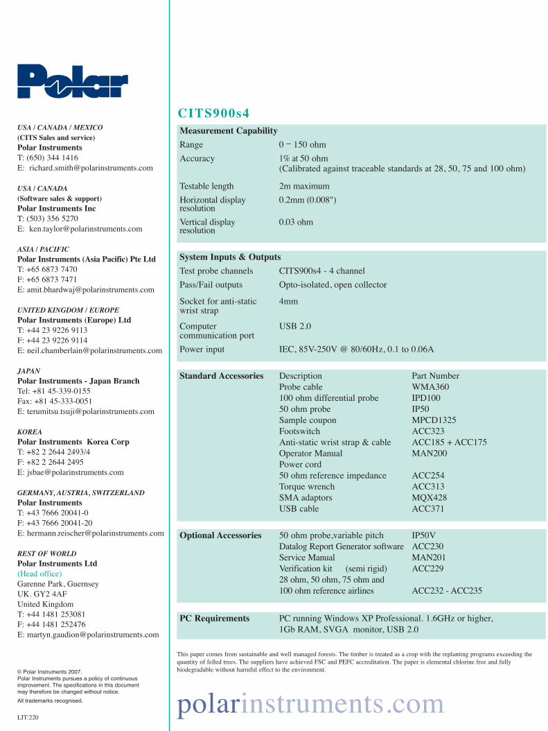
CITS900s4
Standard Accessories Description Part NumberProbe cable WMA360100 ohm differential probe IPD10050 ohm probe IP50 Sample coupon MPCD1325Footswitch ACC323Anti-static wrist strap & cable ACC185 + ACC175Operator Manual MAN200Power cord50 ohm reference impedance ACC254Torque wrench ACC313SMA adaptors MQX428USB cable ACC371
Optional Accessories 50 ohm probe,variable pitch IP50VDatalog Report Generator software ACC230Service Manual MAN201Verification kit (semi rigid) ACC22928 ohm, 50 ohm, 75 ohm and100 ohm reference airlines ACC232 - ACC235
PC Requirements PC running Windows XP Professional. 1.6GHz or higher, 1Gb RAM, SVGA monitor, USB 2.0
Measurement Capability
Range 0 _ 150 ohm
Accuracy 1% at 50 ohm (Calibrated against traceable standards at 28, 50, 75 and 100 ohm)
Testable length 2m maximum
Horizontal display 0.2mm (0.008")resolution
Vertical display 0.03 ohmresolution
System Inputs & Outputs
Test probe channels CITS900s4 - 4 channel
Pass/Fail outputs Opto-isolated, open collector
Socket for anti-static 4mmwrist strap
Computer USB 2.0communication port
Power input IEC, 85V-250V @ 80/60Hz, 0.1 to 0.06A
polarinstruments.com
USA / CANADA / MEXICO (CITS Sales and service)Polar InstrumentsT: (650) 344 1416E: [email protected]
USA / CANADA(Software sales & support)Polar Instruments IncT: (503) 356 5270E: [email protected]
ASIA / PACIFICPolar Instruments (Asia Pacific) Pte LtdT: +65 6873 7470F: +65 6873 7471E: [email protected]
UNITED KINGDOM / EUROPEPolar Instruments (Europe) LtdT: +44 23 9226 9113F: +44 23 9226 9114E: [email protected]
JAPANPolar Instruments - Japan BranchTel: +81 45-339-0155Fax: +81 45-333-0051E: [email protected]
KOREAPolar Instruments Korea CorpT: +82 2 2644 2493/4F: +82 2 2644 2495E: [email protected]
GERMANY, AUSTRIA, SWITZERLANDPolar Instruments T: +43 7666 20041-0F: +43 7666 20041-20E: [email protected]
REST OF WORLDPolar Instruments Ltd(Head office)Garenne Park, GuernseyUK. GY2 4AFUnited KingdomT: +44 1481 253081F: +44 1481 252476E: [email protected]
© Polar Instruments 2007.Polar Instruments pursues a policy of continuous improvement. The specifications in this document may therefore be changed without notice.
All trademarks recognised.
LIT:220
This paper comes from sustainable and well managed forests. The timber is treated as a crop with the replanting programs exceeding thequantity of felled trees. The suppliers have achieved FSC and PEFC accreditation. The paper is elemental chlorine free and fully biodegradable without harmful effect to the environment.