Embed Size (px)
Citation preview
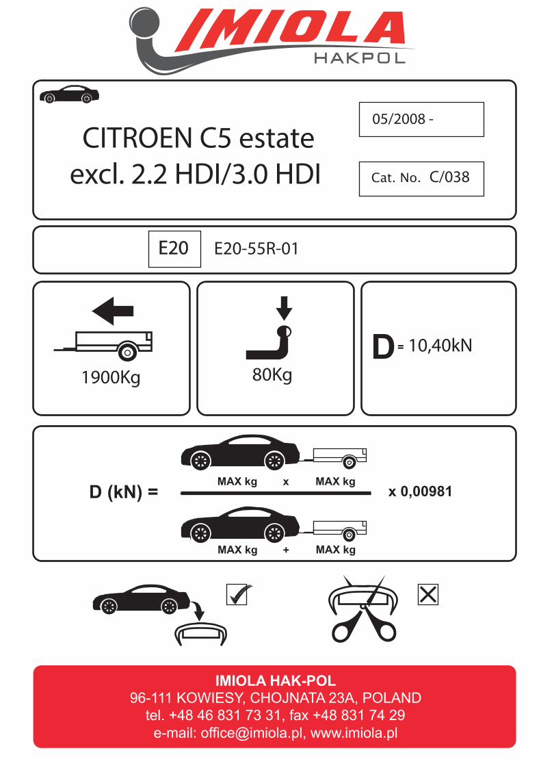
Cat. No.
1900Kg 80Kg
05/2008 -
C/038
10,40kN
E20-55R-01e20
D (kN) = MAX kg MAX kg
MAX kg MAX kg
x
+
x 0,00981
D =
CITROEN C5 estate
excl. 2.2 HDI/3.0 HDI
E20
0Km 1000Km
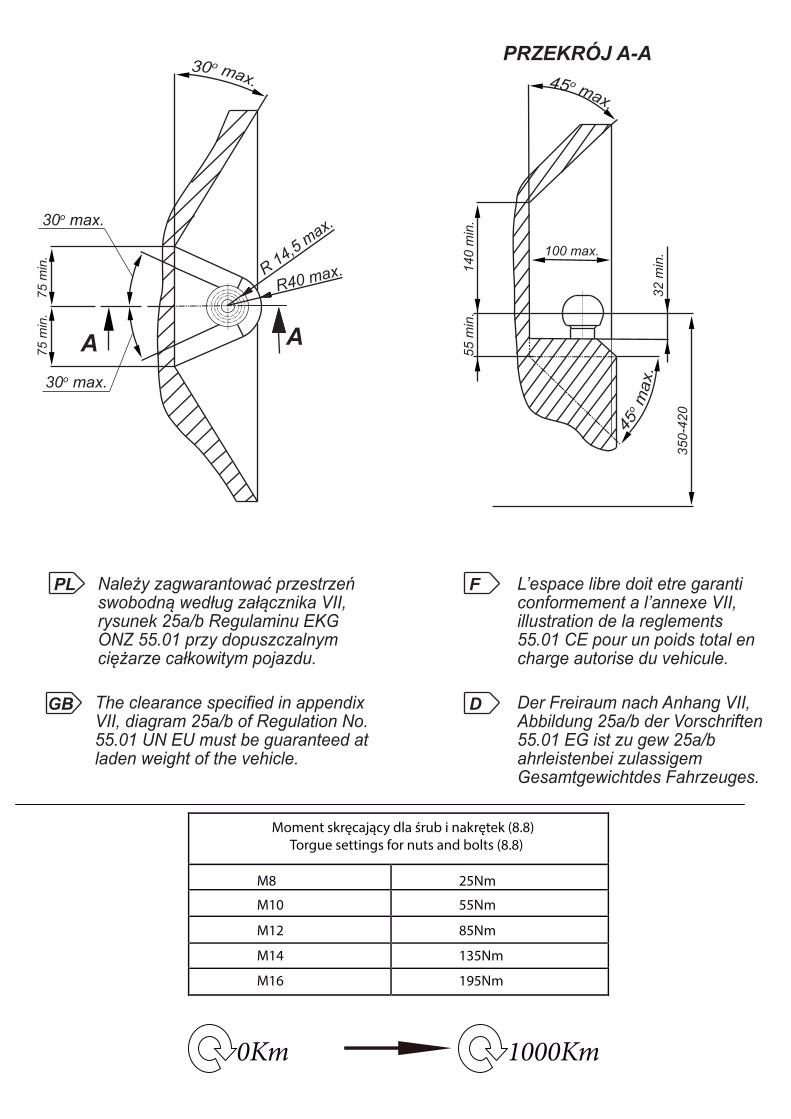
Moment skręcający dla śrub i nakrętek (8.8)
Torgue settings for nuts and bolts (8.8)
M8
M10
M12
M14
M16
25Nm
55Nm
85Nm
135Nm
195Nm
R 14,5
max.
30o max.
30o max.
R40 max.
75 m
in.
75 m
in.
AA
100 max.
140 m
in.
PRZEKRÓJ A-A
55 m
in.
32 m
in.
350
-420
PL Należy zagwarantować przestrzeńswobodną według załącznika VII,rysunek 25a/b Regulaminu EKGONZ 55.01 przy dopuszczalnym ciężarze całkowitym pojazdu.
L’espace libre doit etre garanticonformement a l’annexe VII,illustration de la reglements 55.01 CE pour un poids total en charge autorise du vehicule.
The clearance specified in appendix VII, diagram 25a/b of Regulation No.55.01 UN EU must be guaranteed atladen weight of the vehicle.
Der Freiraum nach Anhang VII, Abbildung 25a/b der Vorschriften 55.01 EG ist zu gew 25a/b ahrleistenbei zulassigem Gesamtgewichtdes Fahrzeuges.
GB
F
D
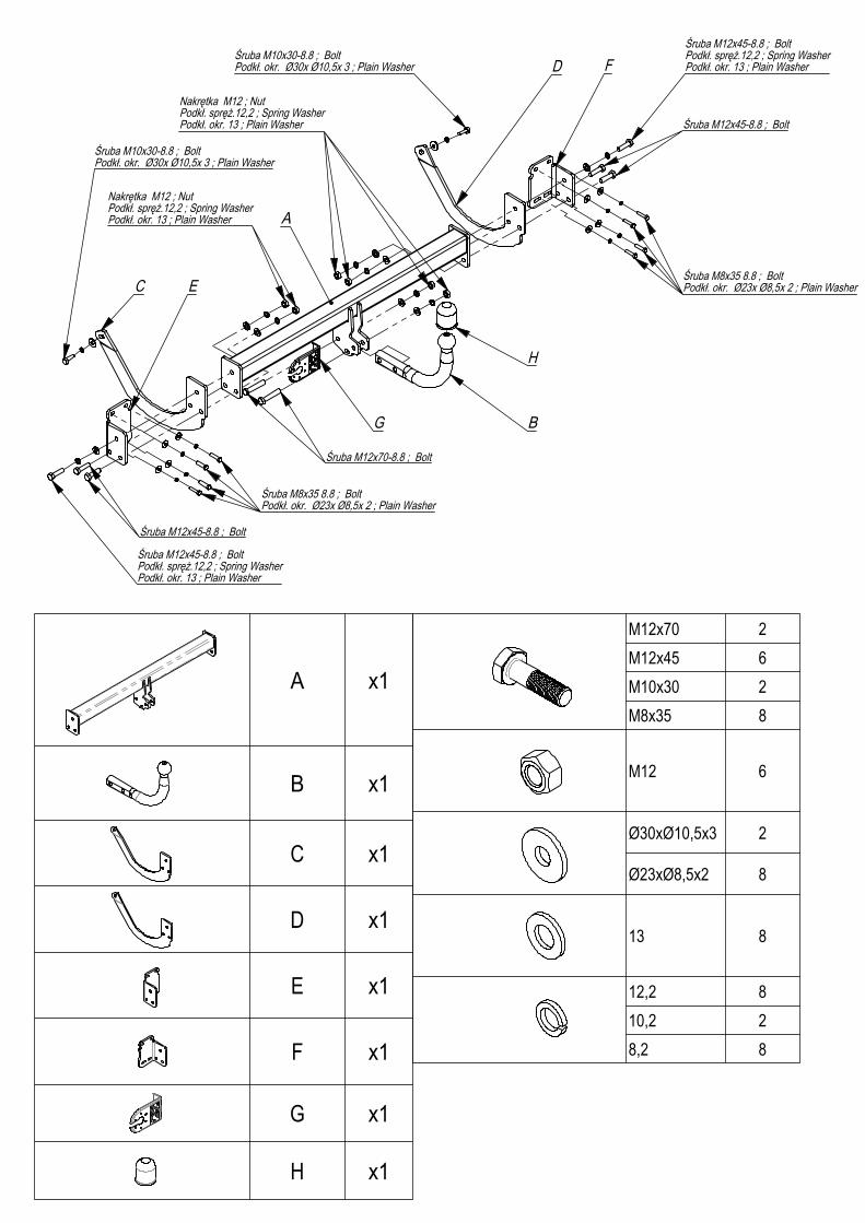
x1
x1
x1
x1
x1
x1
x1
x1
M12x70 2
M12x45
M10x30 2
M8x35 8
M12
Ø30xØ10,5x3 2
Ø23xØ8,5x2 8
13 8
12,2 8
10,2 2
8,2 8
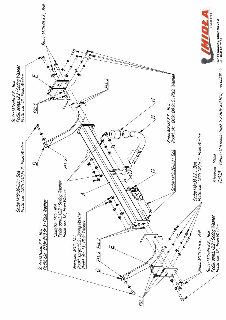
A
B
C
D
E
F
Pkt
. 2
Pkt
. 2
Pkt
. 3
Pkt
. 3
Pkt
. 1
Pkt
. 1
GH
C/0
38M
arka
od 0
5/08
- >
Citr
oen
C-5
est
ate
(exc
l. 2.
2 H
DI/
3.0
HD
I)96
-111
Kow
iesy
, Cho
jnat
a 23
Ate
l. +4
8 46
831
73
31
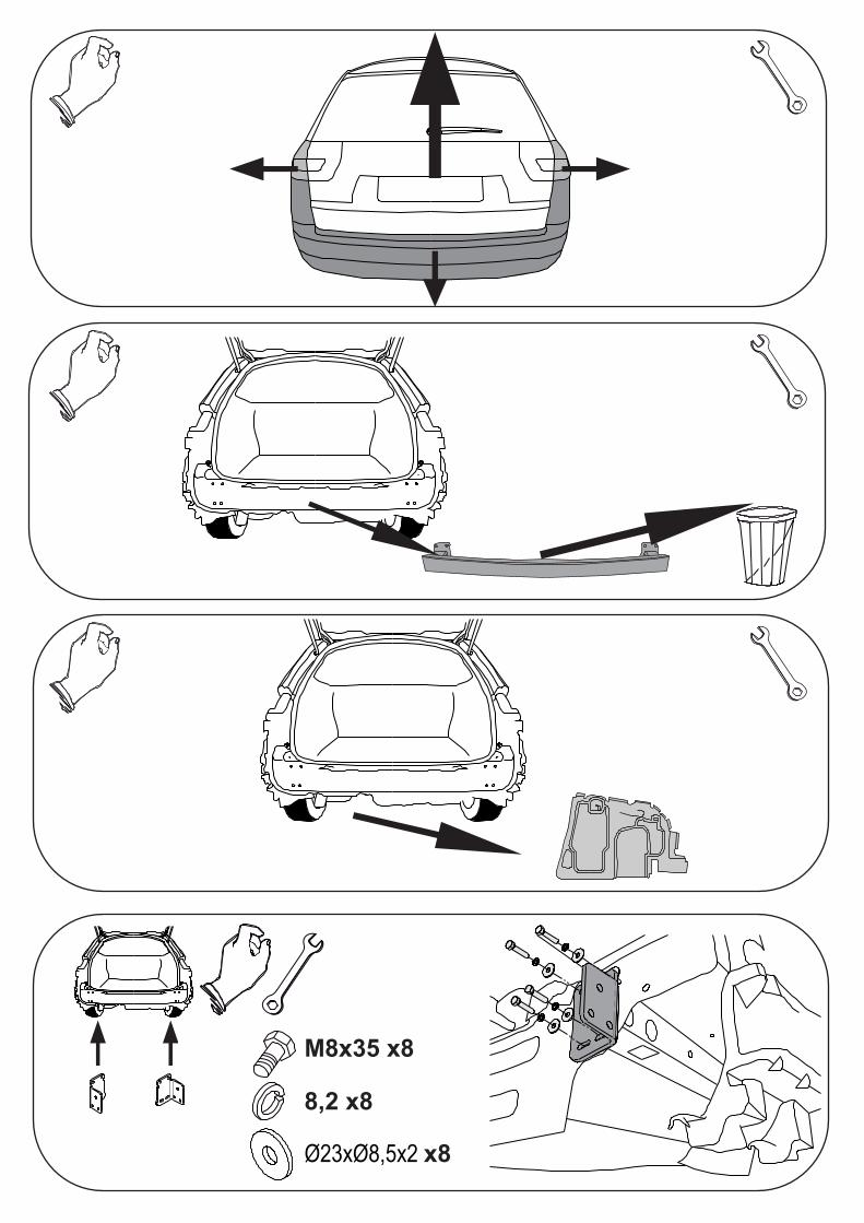
• Zdemontować tylne lampy.
• Odkręcić zderzak i jego plastikowe wzmocnienie.
• Przykręcić do tylnego pasa elementy haka E i F śrubami M8x35 8.8.
• Odszukać na zewnętrznej stronie podłużnic i udrożnić technologiczne otwory.
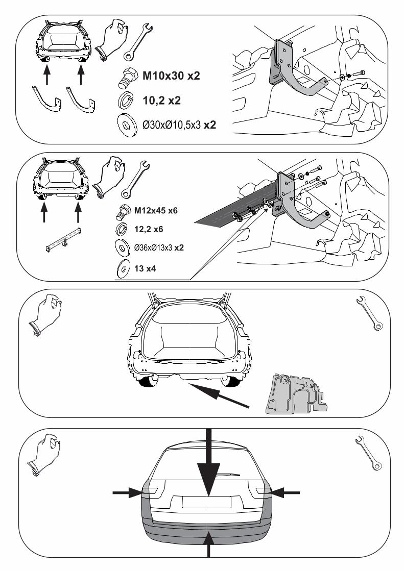
• Elementy C i D przykręcić do boków podłużnic śrubami M10x40 8.8 (pkt 2).
• Przykręcić belkę haka A do elementów E i F oraz C i D śrubamiM12x45 8.8 (pkt 3).
• Dokręcić wszystkie śruby z momentem według tabeli.
• Podłączyć instalację elektryczną.
• Przykręcić zderzak.
• Przykręcić kulę i blachę gniazdka elektrycznego.
• Disassemble the rear lamps.
• Unscrew the bumper and its plastic reinforcement.
• Screw the elements E and F to the rear belt with bolts M8x35 8.8.
• Find the technological holes on the external side of the metal clamps and
make them permeable.
• Screw the elements C and D to the sides of the metal clamps with
bolts M10x40 8.8 (point 2).
• Screw the main bar A to the elements E, F and C, D with bolts M12x45 8.8 (point 3).
• Tighten all the bolts according to the torque setting- see the table.
• Connect the electric wires.
• Screw the bumper.
• Fix the ball and electric plate.
• Dévisser les lampes et le pare-chocs.
• Dévisser la poutre de chocs (elle ne sera plus utilisée).
• Dévisser le carter du fond de la voiture du gauche.
• Visser les éléments E et F à la poutre du crochet A avec les boulons M12x45 8.8 (point 3).
• In�ler dans la bande postérieure la poutre du crochet A avec les éléments E et F �xés
et ensuite serrer tout à travers des trous technologiques restés après le démontage
de la poutre de pare-chocs avec les boulons M8x35 8.8 (point 1).
• Serrer les éléments C et D à travers les trous dans le longeron en utilisant
les boulons M10x40 8.8. (point 2) et ensuite les serrer au crochet d'attelage (A).
• Serrer le carter du côté gauche.
• Monter le pare-chocs et les lampes.
• Visser la boule et la tôle de la prise electrique à l'aide des boulons M12x70 8.8.
• Serrer tous les boulons avec un couple de serrage selon tableau.
• Raccorder le circuit électrique.
M8x35 x8
8,2 x8
Ø23xØ8,5x2 x8
M10x30 x2
10,2 x2
Ø30xØ10,5x3 x2
M12x45 x6
12,2 x6
Ø36xØ13x3 x2
13 x4
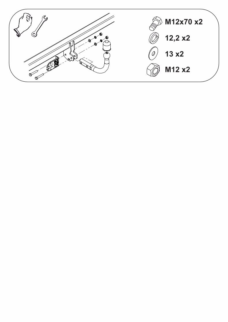
M12x70 x2
12,2 x2
13 x2
M12 x2