Embed Size (px)
Citation preview

Cisco Video Surveillance Solution Reference Network Design GuideJune, 2013
Americas HeadquartersCisco Systems, Inc.170 West Tasman DriveSan Jose, CA 95134-1706 USAhttp://www.cisco.comTel: 408 526-4000
800 553-NETS (6387)Fax: 408 527-0883
Text Part Number: OL-29538-01

THE SPECIFICATIONS AND INFORMATION REGARDING THE PRODUCTS IN THIS MANUAL ARE SUBJECT TO CHANGE WITHOUT NOTICE. ALL STATEMENTS, INFORMATION, AND RECOMMENDATIONS IN THIS MANUAL ARE BELIEVED TO BE ACCURATE BUT ARE PRESENTED WITHOUT WARRANTY OF ANY KIND, EXPRESS OR IMPLIED. USERS MUST TAKE FULL RESPONSIBILITY FOR THEIR APPLICATION OF ANY PRODUCTS.
THE SOFTWARE LICENSE AND LIMITED WARRANTY FOR THE ACCOMPANYING PRODUCT ARE SET FORTH IN THE INFORMATION PACKET THAT SHIPPED WITH THE PRODUCT AND ARE INCORPORATED HEREIN BY THIS REFERENCE. IF YOU ARE UNABLE TO LOCATE THE SOFTWARE LICENSE OR LIMITED WARRANTY, CONTACT YOUR CISCO REPRESENTATIVE FOR A COPY.
The Cisco implementation of TCP header compression is an adaptation of a program developed by the University of California, Berkeley (UCB) as part of UCB’s public domain version of the UNIX operating system. All rights reserved. Copyright © 1981, Regents of the University of California.
NOTWITHSTANDING ANY OTHER WARRANTY HEREIN, ALL DOCUMENT FILES AND SOFTWARE OF THESE SUPPLIERS ARE PROVIDED “AS IS” WITH ALL FAULTS. CISCO AND THE ABOVE-NAMED SUPPLIERS DISCLAIM ALL WARRANTIES, EXPRESSED OR IMPLIED, INCLUDING, WITHOUT LIMITATION, THOSE OF MERCHANTABILITY, FITNESS FOR A PARTICULAR PURPOSE AND NONINFRINGEMENT OR ARISING FROM A COURSE OF DEALING, USAGE, OR TRADE PRACTICE.
IN NO EVENT SHALL CISCO OR ITS SUPPLIERS BE LIABLE FOR ANY INDIRECT, SPECIAL, CONSEQUENTIAL, OR INCIDENTAL DAMAGES, INCLUDING, WITHOUT LIMITATION, LOST PROFITS OR LOSS OR DAMAGE TO DATA ARISING OUT OF THE USE OR INABILITY TO USE THIS MANUAL, EVEN IF CISCO OR ITS SUPPLIERS HAVE BEEN ADVISED OF THE POSSIBILITY OF SUCH DAMAGES.
Cisco and the Cisco logo are trademarks or registered trademarks of Cisco and/or its affiliates in the U.S. and other countries. To view a list of Cisco trademarks, go to this URL: www.cisco.com/go/trademarks. Third-party trademarks mentioned are the property of their respective owners. The use of the word partner does not imply a partnership relationship between Cisco and any other company. (1110R)
Any Internet Protocol (IP) addresses and phone numbers used in this document are not intended to be actual addresses and phone numbers. Any examples, command display output, network topology diagrams, and other figures included in the document are shown for illustrative purposes only. Any use of actual IP addresses or phone numbers in illustrative content is unintentional and coincidental.
Cisco Video Surveillance Solution Reference Network Design Guide © 2013 Cisco Systems, Inc. All rights reserved.

OL-29538-01
C O N T E N T S
Preface v
Purpose v
Audience v
Scope v
Assumptions v
Caveats vi
Related Documentation vi
Command Syntax Conventions vi
C H A P T E R 1 Solution Definition 1-1
Solution Overview 1-1
Video Endpoints 1-1
Client Endpoints 1-2
Video Surveillance Manager 1-2
Architectural Framework 1-2
Design Methodology 1-4
Design Objectives 1-4
Design Approach 1-5
Requirements Specification 1-5
Architecture Vision 1-6
Architecture Review 1-6
Solution Design 1-6
Solution Implementation 1-6
C H A P T E R 2 Enterprise Design Considerations 2-1
Reference Architectures 2-1
Centralized Architecture 2-1
Characteristics 2-1
Design Principles 2-2
Branch Architecture 2-4
Characteristics 2-4
Design Principles 2-5
Distributed Architecture 2-6
Characteristics 2-6
iCisco Video Surveillance Solution Reference Network Design Guide

Contents
Design Principles 2-7
Campus Network Design 2-8
Hierarchical Model 2-8
Access Layer 2-9
Distribution Layer 2-9
Core Layer 2-10
Layer 2 Design 2-10
LAN Switching 2-10
Virtual LAN 2-11
Spanning Tree Protocol (STP) 2-12
Trunking 2-13
Etherchannels 2-13
Layer 3 Design 2-14
IP Addressing 2-14
IP Unicast Routing 2-15
IP Multicast Routing 2-16
Boundary Design 2-18
Layer 2 Distribution 2-18
Layer 3 Distribution 2-19
Layer 3 Access 2-20
Virtual Switching System 2-21
C H A P T E R 3 Network Video Considerations 3-1
Video Compression 3-1
Compression Algorithms 3-1
Chroma subsampling 3-1
Spatial compression 3-1
Temporal compression 3-2
Group of Pictures 3-2
Intra Frames 3-2
Predictive Frames 3-2
Bidirectional Predictive Frames 3-2
Video Codecs 3-3
Motion JPEG 3-3
MPEG-4 3-4
H.264 3-4
Stream Quality 3-5
Resolution 3-5
Bit Rate 3-6
iiCisco Video Surveillance Solution Reference Network Design Guide
OL-29538-01

Contents
Frame Rate 3-6
Quantization Factor 3-7
C H A P T E R 4 Media Flow Considerations 4-1
Data Flow 4-1
Media Transport Protocols 4-3
Real Time Streaming Protocol (RTSP) 4-3
OPTIONS 4-3
DESCRIBE 4-3
SETUP 4-4
PLAY 4-5
PAUSE 4-5
TEARDOWN 4-5
Real-Time Transport Protocol (RTP) 4-6
Real Time Control Protocol (RTCP) 4-6
Flow Characterization 4-7
Video Endpoint-to-Media Server Flow 4-7
RTP over UDP 4-7
RTP over TCP 4-10
Media Server-to-Client Endpoint Flow 4-12
C H A P T E R 5 Network Services Considerations 5-1
Network Time Protocol 5-1
Dynamic Host Control Protocol 5-2
Simple Network Management Protocol 5-5
C H A P T E R 6 Quality of Service Considerations 6-1
QoS Processing 6-1
Classification and Marking 6-1
Congestion Management and Avoidance 6-4
Routers 6-4
LAN Switches 6-7
Traffic Shaping and Policing 6-7
C H A P T E R 7 Network Performance Considerations 7-1
Bandwidth 7-1
Packet Loss 7-3
Latency 7-4
iiiCisco Video Surveillance Solution Reference Network Design Guide
OL-29538-01

Contents
Jitter 7-5
C H A P T E R 8 Network Management Considerations 8-1
Endpoint Provisioning 8-1
IOS Device Sensor 8-1
Auto Smartport (ASP) Macros 8-2
Dynamic Host Control Protocol (DHCP) 8-4
Media Services Interface (MSI) 8-4
Network Validation 8-4
Proactive Monitoring 8-9
Reactive Monitoring 8-13
Mediatrace Poll 8-14
Hops Poll 8-14
System Poll 8-15
Performance Monitor Poll 8-17
Mediatrace Session 8-20
A P P E N D I X A Related Documentation A-1
Cisco Video Surveillance Documentation A-1
Design Documentation A-4
Cisco UCS Platform and VM Documentation A-5
G L O S S A R Y
ivCisco Video Surveillance Solution Reference Network Design Guide
OL-29538-01

Preface
PurposeThis document summarizes high-level design recommendations and best practices for implementing Cisco Video Surveillance on the enterprise network infrastructure. In some instances, existing network equipment and topologies have the necessary configuration and performance characteristics to support high-quality IP Video Surveillance. In other instances, network hardware might require upgrading or reconfiguration to support increased bandwidth needed to support video. Quality-of-service (QoS) techniques are important for any design because video has similar—in some instances, more stringent—requirements than VoIP for loss, latency, and jitter.
AudienceThe intended audiences for this Solution Reference Network Design (SRND) document are architects and engineers responsible for the design of the IP Video Surveillance solution.
ScopeThe scope of this document covers the network design considerations for Cisco VSM 7.0. Product design, while discussed, is not emphasized and is only considered for the purpose of completeness. This SRND should be used in conjunction with the product-specific collateral listed in the “Related Documentation” section.
AssumptionsThe information presented in this document assumes that the reader has a working knowledge of, and experience with the TCP/IP stack, and internet working technologies. Knowledge of the Cisco Video Surveillance Manager (VSM) suite of applications is also assumed.
vCisco Video Surveillance Solution Reference Network Design Guide
OL-29538-01

CaveatsEach network environment is unique, and as such the considerations and recommendations presented in this document must be judiciously and competently applied in the context of the current network architecture deployed in the organization.
Cisco will not be held responsible for any network changes effected that adversely impact the network or business operations, including but not limited to, performance, reliability or scalability.
Related DocumentationSee the “Related Documentation” section.
Command Syntax ConventionsTable 1 describes the syntax used with the commands in this document.
Table 1 Command Syntax Guide
Convention Description
boldface Commands and keywords.
italic Command input that is supplied by you.
[ ] Keywords or arguments that appear within square brackets are optional.
{ x | x | x } A choice of keywords (represented by x) appears in braces separated by vertical bars. You must select one.
^ or Ctrl Represent the key labeled Control. For example, when you read ^D or Ctrl-D, you should hold down the Control key while you press the D key.
screen font Examples of information displayed on the screen.
boldface screen font Examples of information that you must enter.
< > Nonprinting characters, such as passwords, appear in angled brackets.
[ ] Default responses to system prompts appear in square brackets.
viCisco Video Surveillance Solution Reference Network Design Guide
OL-29538-01

Cisco Video SurvOL-29538-01
C H A P T E R 1
Solution DefinitionSolution OverviewThe Cisco IP Video Surveillance (IPVS) solution is a platform for the delivery, management and monitoring of video across the enterprise network.
The solution consists of the following key components as illustrated below:
Figure 1-1 Key Solution Components
Video EndpointsIP video traffic is generated by IP cameras and encoders and is transported over the network to client endpoints and managed by the Video Surveillance Manager (VSM). Encoders are required to convert video signals from analog cameras to digital format so that they can be transported over the IP network.
Cisco provides a range of IP cameras for various use-cases, including fixed and Pan, Tilt, Zoom (PTZ) models that are capable of streaming in both standard and high-definition.
1-1eillance Solution Reference Network Design Guide

Chapter 1 Solution DefinitionArchitectural Framework
In addition, the Cisco VSM application provides support for several third-party IP cameras and encoders. For more information, please contact your Cisco account representative to get the most up to date list of supported devices.
Client Endpoints The client endpoints are end-user workstations that include the following applications:
• The Internet Explorer web browser used to access the Cisco VSM Operations Manager for configuration, monitoring and other day-to-day operational and administrative tasks.
• The Cisco Video Surveillance Safety and Security Desktop (Cisco SASD) application used to monitor live and recorded video.
Due to the resource requirements for rendering video streams, workstations must meet or exceed specific hardware specifications as stipulated in the Cisco Video Surveillance Manager Workstation Baseline Specifications document available at http://www.cisco.com/en/US/products/ps10818/prod_technical_reference_list.html).
Video Surveillance ManagerCisco Video Surveillance Manager (VSM) is a suite of video management applications comprising of Operations Manager (VSOM) and Media Server (VSMS) that utilize the network as a platform for delivery of live streaming as well as recorded video from video endpoints to end users at client endpoints.
The VSM server applications can be hosted on one of the following:
• A Red Hat Linux-based Multi-Services Platform (MSP) appliance.
• A SUSE Linux-based Multi-Services Platform (MSP) appliance.
• Virtual machines (VMs) running on either Linux platform.
All requests for live and archived video are made from client endpoints to the Media Server; therefore, the server in effect acts as a proxy for the video endpoints. The Media Server also acts as a de-jitter buffer to smooth out any delay variation in the arrival of video packets from the video endpoints.
The VSM application also provides high availability for the Media Server application to mitigate service outage in the event of a server fault.
For more information on the products and solution components referenced above, please consult the Related Documentation section of this Guide.
Architectural FrameworkThe IP Video Surveillance architectural framework refers to a set of building blocks that are used as a guiding tool when designing and evaluating a Cisco video surveillance solution. Based on the customer-stated business and technical requirements, and the application of industry standards and best practices, the right IP Video Surveillance solution can be developed and built for an organization.
The enterprise IP Video Surveillance environment is built on a solid foundational framework that is composed of a stack of four horizontal building blocks that define the solution architecture, as well as a vertical services overlay that enables its successful implementation and sustenance.
1-2Cisco Video Surveillance Solution Reference Network Design Guide
OL-29538-01

Chapter 1 Solution DefinitionArchitectural Framework
The IP Video Surveillance solution framework is illustrated below:
Figure 1-2 IP Video Surveillance Architectural Framework
Each block in the stack has a significant and integral role to play in the solution architecture to be developed and should thus be exhaustively addressed to produce a scalable and resilient solution.
The enterprise architectures block defines the structure of the network deployment environment on which the IP Video Surveillance solution will be implemented. In general, there are three main architecture models: centralized, branch and distributed. Each architecture model has unique requirements and considerations, though there are areas of overlap.
The infrastructure platforms block describes the major infrastructure components that comprise the IP Video Surveillance environment. This layer includes the Local Area Network (LAN) and Storage Area Network (SAN) that form the building blocks of the network design, as well as the Unified Computing System (UCS) and Multiservice Platform (MSP) appliances onto which all applications are hosted.
The management instrumentation block defines the system tools and processes that enable the scalable management and flexible monitoring of the IP Video Surveillance solution. These tools leverage embedded instrumentation within IOS, NXOS and MSP devices to extract relevant data points for assessing the total health of the solution, as well as for fault isolation and rapid resolution.
The endpoints and applications block sits at the very top of the stack, leveraging the infrastructure and management capabilities offered by the lower layers. This layer defines the sources and consumers of video data, including Video Surveillance Manager Server applications that manage these endpoint devices as well as video traffic on the network.
The services block comprises the service offerings that support the IP Video Surveillance architecture. These include security, business continuity and optimization services. Security services are composed of the features and technologies necessary for securing the infrastructure and application environments.
1-3Cisco Video Surveillance Solution Reference Network Design Guide
OL-29538-01

Chapter 1 Solution DefinitionDesign Methodology
Security policies could be applied on the network devices, servers and endpoints. Business continuity focuses on maintaining an organization’s IP Video Surveillance systems during and after a disruption, and consist of both high availability and disaster recovery strategies. Optimization services provide features that enhance the performance and intelligence of applications and the network environment, including load balancing and caching. These services are not only related but dependent on each other, supporting a fully functional solution architecture.
The solution framework forms the basis of the design and architecture of the IP Video Surveillance environment, and as such it is important to understand its relevance. The following sections describe these considerations in further detail.
Design MethodologyNetwork design considerations for IP Video Surveillance solutions are easy to overlook, and often are, because it is assumed that the underlying network should be able to handle any type of traffic while delivering acceptable performance.
While this may be true for very small deployments, it is most certainly a recipe for problems for relatively larger deployments, and also for the time in the future when this small deployment needs to grow. An IP Video Surveillance network that has not been designed in a systematic fashion will invariably run into problems from the beginning of the implementation stage.
Network design is as much about developing the most appropriate solution given a set of requirements, as much as it is about documenting these requirements, design decisions and proposed architecture. This allows new team members to easily understand what problems the design solves, how the system operates and how to extend and expand the network when needed.
Design ObjectivesAn effective IP Video Surveillance solution design should strive to meet the following objectives:
• Customer-focus – the solution must be designed with a goal to meet the customer-stated requirements and expectations. In reality, sometimes not all requirements are met by an existing engineering solution in Cisco’s product portfolio, which is why it is necessary to distinguish between “must-have’s” (needs) and “nice-to-have’s” (wants). Prioritization ensures that the most important requirements are met either through product enhancements or evaluation of external products to close the requirements gap.
• Scalability – the solution must be designed with a goal to allow for growth in capacity and functionality. Sound scalable and extensible design allows for implementation of changes and deployment of additional management servers, users and endpoints without requiring a major re-design, or significantly impacting the performance and operation of the existing environment.
• Determinism – the solution must be designed to be predictable. A predictable solution means that, given a set of symptoms or conditions, the logical operation of the solution – including data flows, actions executed, etc., – can be determined. This is especially useful for fault isolation and resolution.
• Accountability – the design choices made when creating a solution must be responsible, defensible and explainable. It is recommended to subject the design to a peer review under the counsel of competent colleagues in order to ensure that the business and technical case being presented to the end customer is sound and passes muster.
1-4Cisco Video Surveillance Solution Reference Network Design Guide
OL-29538-01

Chapter 1 Solution DefinitionDesign Methodology
• Survivability – the solution must be designed to maintain maximum availability and functionality of the solution components under the existence of one or more failure conditions in the deployment environment. Designing for redundancy at the logical and physical level is critical to producing an optimal solution.
Design ApproachThe following figure illustrates the approach to IP Video Surveillance design:
Figure 1-3 Methodology
Requirements Specification
During this phase, all solution requirements and expectations should be gathered from discussions with the customer. There are different types of requirements to gather when starting the solution design process:
• Business requirements – these are high-level requirements that describe what goals the solution should achieve for the customer and how it benefits their business operations. Examples could include: “The solution should provide a means to constantly monitor at-risk patients in the hospital wards using video”.
1-5Cisco Video Surveillance Solution Reference Network Design Guide
OL-29538-01

Chapter 1 Solution DefinitionDesign Methodology
• Functional requirements – these requirements provide a more detailed specification of how the system should work. For example: “The solution must provide N+1 high availability for the VSM application and all camera streams at the central and remote campuses”.
• Technical requirements – these requirements indicate what technical specifications the solution must adhere to. These could include technology preferences, best-practices and industry standards. Examples include: “All video streams must use the H.264 codec, UDP transport and 1Mbps bit rate”.
It is important to ensure that the list of requirements gathered is as exhaustive as possible so as to mitigate instances of re-design of the solution in later phases.
Architecture Vision
The architecture vision essentially provides a high-level response to the requirements gathered. This response presents the technical approach that will be adopted to meet the stated requirements.
During this phase a high-level architecture is developed that depicts the logical topology of the proposed solution. In addition, the vision also describes what platforms – infrastructure, application, storage, etc. – would be used in the solution.
Architecture Review
The architecture review phase provides an opportunity for the other stakeholders and subject matter experts involved in the project to review the proposed design. This group may include the customer and partner teams, as well as other internal or external audiences.
The purpose of the review is to ensure that the solution proposal is feasible given the deployment environment and resource expectations, and that all the stated requirements have been considered and addressed. Not all requirements may be met in the proposed solution, and in such instances justifications for the design decisions taken should be offered.
Solution Design
It is during this phase that the detailed design of the solution is developed. At this point all requirements have been gathered and considered, and the proposed design has been reviewed and accepted. The requirements gathered are further unpacked and design choices are made where variations exist.
The rest of this SRND focuses on the low-level considerations that must be taken into account when designing or evaluating the network component of the IP Video Surveillance solution.
Solution Implementation
While not a focus of this SRND, this phase is included for completeness. During this phase, the solution is delivered as per the design developed.
1-6Cisco Video Surveillance Solution Reference Network Design Guide
OL-29538-01

Cisco Video SurvOL-29538-01
C H A P T E R 2
Enterprise Design ConsiderationsThis chapter discusses the considerations that need to be taken into account when designing the enterprise IP Video Surveillance network.
Reference ArchitecturesEnterprise IP Video Surveillance architectures are characterized based on the following factors:
• Network model (LAN/MAN or WAN)
• Location of the VSM servers
• Number of Operations Manager servers
• Number of Media Servers
The following sections describe the different architecture models that can be adopted in terms of their characterization and principles of design.
Centralized Architecture
Characteristics
The centralized IP Video Surveillance architecture is characterized by the existence of a single Operations Manager server that manages one or more Media Servers at the same organizational and geographical region. A campus with one or more locations that are interconnected by a Local Area Network (LAN) or Metropolitan Area Network (MAN) defines this region.
In general, centralized architectures are classified as “medium-sized” deployments, which consist of 20 or fewer media servers, 1000, or fewer video endpoints and 20 or fewer active client endpoints, in a single location.
2-1eillance Solution Reference Network Design Guide

Chapter 2 Enterprise Design ConsiderationsReference Architectures
The following sample topology illustrates this model:
Figure 2-1 Centralized Architecture
In the figure above, the network spans two campuses that are interconnected over a LAN or MAN. This implies that the campuses are within the same general geographic area with the network providing a high-speed back-haul, e.g. 1Gbps, 10Gbps or 40Gbps. The VSM servers can be located at either or both campuses – Building A and Building 1.
Design Principles
Compute
Computational resources for VSM servers, primarily CPU and memory, are provided either by MSP’s in a physical environment or UCS’s in a virtualized environment. The provisioning of these resources for VSM appliances should be guided by the expected workload from video endpoints, server processing activities and servicing requests from client endpoints.
Cisco provides recommendations for sizing virtual environments in the VSM on UCS Deployment Guides found at http://www.cisco.com/en/US/prod/collateral/vpndevc/ps6918/ps9145/ps9152/data_sheet_c78-712809.html.
MSPs that support Cisco Video Surveillance are equipped with up to a single-socket, quad-core processor and 2GB of RAM. They provide a simple and standardized platform for deploying VSM in centralized architectures. By that same token, the caveat that presents itself is that computational resources cannot be grown to adapt to growth in workloads over time. So either the initial sizing will need to be over-provisioned in anticipation of future resource demands, or multiple appliances would be required to drive the same workload.
2-2Cisco Video Surveillance Solution Reference Network Design Guide
OL-29538-01

Chapter 2 Enterprise Design ConsiderationsReference Architectures
For VSM instances that are virtualized on the UCS platform, these concerns are addressed due to the ability of UCS appliances to handle larger CPU and memory capacities. VSM virtual appliances can be hosted on B-series hosts that provide a dense deployment environment serviced by up to two-socket, 6-core processors and up to 384GB of RAM. C-series servers can be provisioned with up to two-socket, 8-core processors and up to 384GB of RAM. Therefore, these VSM virtual machines can be provisioned with more memory and processor capacity flexibly when required.
Network
For simple deployments, the network should be designed with traffic localization in mind. The VSM media servers should be placed as close as possible to video endpoints from which streams are sourced. This will allow relatively higher quality video to be recorded locally, without being required to traverse the network, which could result in additional latency and higher potential for packet loss.
Sophisticated networks that have end-to-end QoS deployed, with the recommended per-hop behavior (PHB) applied to the video traffic class, allow video traffic to traverse the network to a centralized location. For example in the data center where the associated VSM media server is located.
Cisco recommends that video traffic should be placed in a separate local VLAN for easy identification and classification. The VLAN should not span multiple switches. Similarly, Ethernet storage and management traffic should be placed in separate VLANs.
A logical and consistent IP addressing scheme should be adopted that allows for simplified management, scalability and route summarization.
Cisco recommends that a network readiness assessment should be carried out to ensure that the network has sufficient capacity to meet the performance requirements for delivering video between endpoints and servers.
Storage
Video traffic requires a significant amount of storage space for recording and as such is the most dominant factor to consider when designing IP Video Surveillance environments. Both MSP and UCS appliances can provide local and remote storage capabilities.
Local storage on the MSP platforms can scale up to 24TB of raw capacity per server, when using the standard 2TB disks in a 12-bay 2RU CPS chassis. The UCS C240 M3, on the other hand, can handle up to 36TB raw capacity per appliance, when using 3TB disks in a 12-bay 2RU chassis.
External storage is supported using fibre channel SAN devices. These devices can scale up in excess of 100TB per appliance. Multilayer directors can be used to provide zoning and other advanced features where multiple hosts and storage devices exist.
In general, virtualized appliances leverage external storage to take advantage of high availability (which requires shared storage), storage scalability and high performance. Local storage on MSP’s is suitable for simple deployments that look for an all-in-one solution for recording and management.
Management
A single Operations Manager server that is located in the central data center manages video endpoints and media server resources. A single VSOM instance can scale management of up to 10,000 video endpoints and up to 250 media servers. For deployment environments that exceed these endpoints and servers, such as city-wide deployments, multiple VSOM instances can be provisioned to provide load-balancing.
2-3Cisco Video Surveillance Solution Reference Network Design Guide
OL-29538-01

Chapter 2 Enterprise Design ConsiderationsReference Architectures
The CPS MSP appliance models provide support for out-of-band management through Intelligent Platform Management Interface (IPMI). Cisco recommends that this interface is configured for IP connectivity to allow for remote access to the BIOS, MegaRAID WebBIOS configuration utility and to carry out power operations (power cycle, power-off, power-on) remotely.
The UCS appliances also provide out-of-band management capabilities through the Cisco Integrated Management Controller (CIMC). The virtual environment is managed using the vSphere client and is used for all aspects of virtual machine provisioning and management.
Branch Architecture
Characteristics
The IP Video Surveillance branch architecture is characterized by the existence of a single Operations Manager server that manages one or more Media Servers at the same organizational and geographical region. This region is defined as an autonomous campus with one or more locations that are interconnected by a Local Area Network (LAN).
In general, branch architectures are classified as “small-sized” deployments which consist of 5 or fewer media servers, 100 or fewer video endpoints and 5 or fewer active client endpoints, in a single location. Multiple such branches can exist in the organization; however, each is characterized as being managed independently of each other.
The following sample topology illustrates this model:
2-4Cisco Video Surveillance Solution Reference Network Design Guide
OL-29538-01

Chapter 2 Enterprise Design ConsiderationsReference Architectures
Figure 2-2 Branch Architecture
Design Principles
Compute
Computational resources at the branch environment are provided either by an MSP appliance for physical environments or the UCS E-series blades for virtual environments. The UCS E-series blade is a Cisco ISR G2 router service module that provides the functionality of a compact, power-optimized, multipurpose x86 64-bit blade server.
The E-series offers a single-socket, up to 6-core processor option with up to 48GB of RAM. These specifications best the MSP appliances, while providing the flexibility of a virtualized environment and functionality of a branch-in-a-box. The caveat to consider is that the ISR G2 is a required component, which could add to the cost factor. However, this could also be an advantage to be leveraged if the router exists already or is to be used to provide other services for the branch.
The MSP is a viable alternative where simplicity is key, and the solution requirements fall within the fixed configuration options available.
Network
The small office/branch office network is typically a flat, switched environment with relatively few endpoints and traffic generated. Video traffic is not expected to traverse long distances from the endpoints to the VSM server; however, Cisco recommends that QoS is implemented to provide differentiated services from other traffic types, especially during periods of relatively higher than normal use.
Depending on the size of the environment, all devices may be placed into a single VLAN and IP addresses sourced from a single subnet. If the IP address space is subdivided for different functions, Cisco recommends that video traffic should be placed in its own VLAN for easy identification and classification.
2-5Cisco Video Surveillance Solution Reference Network Design Guide
OL-29538-01

Chapter 2 Enterprise Design ConsiderationsReference Architectures
Storage
MSP appliances can provide local on-board storage for recording video. E-series blades, on the other hand, do not have sufficient storage capacity to meet most solution recording needs. The blades provide up to 3TB raw capacity for SATA drives. If RAID arrays are created for fault tolerance, this available capacity is further diminished. As a result, whenever E-series blades are required, external storage options will need to be evaluated.
In particular, iSCSI SAN devices are appropriate for this environment to provide the needed storage scalability and at the same time leverage existing Ethernet infrastructure, which lowers the total cost of ownership. The E-series has in-built optimizations for iSCSI, specifically TCP/IP Offload Engine (TOE) and iSCSI hardware offload. These enhancements offload the processing of packet headers to hardware ASICS which translate to a significant performance improvement for VSM applications.
Management
The Operations Manager centrally provides management of the video surveillance environment. As noted earlier, the CPS MSP appliances provide out-of-band management capabilities through IPMI. The UCS E-series blade server has an integrated Emulex Baseboard Management Controller (BMC) that provides for management via IPMI as well as through the CIMC interface.
In addition, the VSM virtual appliances can be managed using the vSphere client interface. This capability is especially important in remote branch environments where IT staff may not be available at every site for monitoring or troubleshooting.
Distributed Architecture
Characteristics
The distributed IP Video Surveillance architecture is characterized by the existence of a single Operations Manager server that manages one or more Media Servers across multiple organizational and geographical regions. These regions are typically composed of a central campus and one or more remote campuses interconnected by a private Wide Area Network (WAN) or the public Internet over a secure virtual private network.
In general, distributed architectures can be classified as a “small”, “medium” or “large” deployment depending on the number of media servers, video and client endpoints, at each location. The principle-defining characteristic of this architecture is that, except for large citywide deployments, a single Operations Manager instance manages multiple media servers and endpoints that are spread out across multiple locations in the enterprise. Each remote location does not operate independently but with dependency on the central location where the VSOM instance is hosted.
2-6Cisco Video Surveillance Solution Reference Network Design Guide
OL-29538-01

Chapter 2 Enterprise Design ConsiderationsReference Architectures
The following sample topology illustrates this model:
Figure 2-3 Distributed Architecture
Design Principles
Network
The network connectivity between the branch and central campus could either be over a private WAN service such as Multi-Protocol Label Switching (MPLS) or Frame Relay, or over the public internet, typically over a secure Virtual Private Network (VPN) service such as IPsec VPN, Dynamic Multipoint VPN (DMVPN) or GET VPN.
2-7Cisco Video Surveillance Solution Reference Network Design Guide
OL-29538-01

Chapter 2 Enterprise Design ConsiderationsCampus Network Design
Remote users can gain access to IP Video Surveillance resources, such as the Operations Manager instance, through an ezVPN or Secure Sockets Layer (SSL) VPN connection.
Bandwidth is typically a limiting factor as traffic traverses the WAN. Users also need to balance the need to record high-fidelity, evidence-quality video with monitoring live video from remote locations. Cisco recommends that in such cases secondary streams of lower resolution and bit rate or frame rate should be considered. The lower quality stream is used for live viewing across the WAN from remote branches to users at the central site, for example, while the higher-quality stream is recorded locally for later retrieval should the need arise.
Cisco recommends that network readiness assessments should be carried out across the central campus to multiple remote locations to determine the appropriate stream settings at which the network can sustain acceptable video performance.
Management
Network management tools should be leveraged to monitor the health of video traffic as it traverses the enterprise network. This is especially important for distributed architectures due to the physical separation and often the lack of trained IT staff at remote locations to assist with troubleshooting and remediation measures.
IOS embedded instrumentation that is leveraged by the Medianet architecture should be employed to provide proactive and reactive monitoring capabilities across the enterprise IP Video Surveillance network. These tools should be used in conjunction with management capabilities available within the campus environments.
Campus Network DesignUnderstanding and designing the structure of the network design is crucial to creating scalable and available campus architectures. This section describes the building blocks of the enterprise campus model as well as considerations for designing the IP Video Surveillance network structure.
Hierarchical ModelThe hierarchical model of network design simplifies the architecture of campus networks into modular components, each representing a functional service layer within the campus hierarchy. A hierarchical design is also important as it avoids the need for a fully meshed node network.
The modularity of the design is important for the following reasons:
Allows the network to scale to meet current as well as future requirements
Allows traffic to flow in a more deterministic pattern
Allows for effective fault isolation and faster resolution
2-8Cisco Video Surveillance Solution Reference Network Design Guide
OL-29538-01

Chapter 2 Enterprise Design ConsiderationsCampus Network Design
The enterprise campus hierarchical model consists of the following layers:
Figure 2-4 Hierarchical Model
Access Layer
The campus access layer aggregates end users and edge devices, such as IP cameras, and provides uplinks to the distribution layer. At layer 2, each switchport creates a single collision domain.
In general, network devices at this layer provide the following features:
Power over Ethernet (PoE) – provides power to PoE-capable edge devices such as IP cameras
QoS trust boundary – traffic flows are typically marked at this layer on ingress at the switchport
Link aggregation – high availability is provided to the distribution layer through Etherchannel or 802.3ad Link Aggregation Control Protocol (LACP)
IGMP snooping – helps control multicast packet flooding for multicast applications
Security services – various security features are typically configured at this layer such as DHCP snooping, 802.1x, port security, Dynamic ARP Inspection and IP source guard
Distribution Layer
The campus distribution layer acts as the services and policy boundary, connecting both access and core layers. Network devices in this layer typically participate in Layer 2 switching on downstream access trunks and Layer 3 switching on upstream core links.
2-9Cisco Video Surveillance Solution Reference Network Design Guide
OL-29538-01

Chapter 2 Enterprise Design ConsiderationsCampus Network Design
In general, network devices at this layer provide the following features:
Redundancy – through Virtual Switching System (VSS) for Catalyst 6500 series switches or first-hop redundancy protocols such as Hot Standby Routing Protocol (HSRP), Virtual Router Redundancy Protocol (VRRP)
Route summarization –summarizes routes from the access layer to the core
Route filtering – limits route advertisements to access devices
Policy-based routing – controlled routing decisions and packet manipulation is carried out at this layer, and also forms the boundary between static and dynamic routing protocols
Layer 2 boundary – VLAN’s are terminated at this layer and traffic is subsequently routed between VLAN’s or to the core for external networks
Core Layer
The campus core layer acts as a high-speed backbone for fast and efficient movement of packets across multiple networks. This layer provides a limited set of services and is designed to be highly available and reliable to allow for rapid adaptation to network changes, for instance rerouting of traffic when network failure occurs.
For smaller campuses, the core can be combined with the distribution to form a collapsed core. In this configuration, the collapsed core must be fully meshed to provide proper connectivity. However, the setup is difficult to scale. Additionally, network changes to one part of the core/distributed layer can result in network disruption in other layers as well. As such, while convenient for small environments, these caveats should be carefully considered.
Layer 2 DesignThe two over-arching design goals for the IP Video Surveillance Layer 2 network are high availability and determinism. The optimal Layer 2 design should provide a measure of redundancy and alternate paths to network destinations, and should also establish predictable patterns for video traffic on the network.
The following features are important in ensuring a suitable Layer 2 design is formed. Considerations for designing the IP Video Surveillance network with these features in mind are discussed in the following sections.
LAN Switching
The goal of the Layer 2 switching or forwarding logic in IOS Catalyst devices is to deliver Ethernet frames to appropriate receivers based on the destination MAC address. Physical switches can either be statically configured with MAC addresses or they can be learned dynamically by inspecting the source MAC address field of incoming frames.
If the MAC address is known, it would be present in the Content-Addressable Memory (CAM) table, along with the associated VLAN ID, egress switchport and timestamp of when the MAC address was last seen. This information will then be used to forward the frame.
If the MAC address is unknown, the forwarding behavior will depend on the type of address:
Unknown unicast – the frame is flooded out all interfaces, except the interface on which the frame was received
Broadcast – the frame is flooded out in the same manner as unknown unicasts
2-10Cisco Video Surveillance Solution Reference Network Design Guide
OL-29538-01

Chapter 2 Enterprise Design ConsiderationsCampus Network Design
Multicast – the frame is flooded out in the same manner as unknown unicasts, except when optimizations such as IGMP are implemented
For the switch to forward on the outgoing interface, the port must be the forwarding state in the STP configuration. Spanning Tree Protocol enables switches overcome the possibility of bridging loops occurring along redundant switching paths.
Virtual LAN
A virtual LAN (VLAN) refers to host devices linked to a subset of switchports that communicate as a logical network segment. VLAN’s are used to limit the size of a broadcast domain, and to assist in allocation and management of subnetworks. As such, VLAN’s form a critical component of hierarchical and modular network designs, and they enable isolation of different traffic aggregates.
Cisco recommends that the following traffic aggregates should be separated by VLAN’s on the network:
Management traffic – generally consists of to-the-box traffic. Examples include Secure Shell (SSH), telnet, vSphere connectivity, Cisco Integrated Management Console (CIMC), Cisco Integrated Management Console Express (CIMCE) and device-generated data traffic such as L2/L3 protocols.
Video traffic – consists of traffic from camera endpoints to media servers, and on to client endpoints
Storage traffic – consists of fiber channel over Ethernet (FCoE) and iSCSI storage traffic
This traffic separation provides for simplicity in managing and monitoring endpoints, and in applying differentiated service levels for these traffic classes.
When traffic is received on an ingress switchport, the frames are tagged with a VLAN ID. By default, VLAN 1 is the tag that is applied to all traffic; however, each switchport can be associated with a different VLAN as shown below:
!! Configure the VLAN database!vlan 22 name management! vlan 23 name video!vlan 24 name storage!
! ! Assign the VLAN’s to switchports!interface FastEthernet1/0/3 switchport mode access switchport access vlan 22!interface FastEthernet1/0/4 switchport mode access switchport access vlan 23!interface range FastEthernet1/0/5 - 6 switchport mode access switchport access vlan 24!
2-11Cisco Video Surveillance Solution Reference Network Design Guide
OL-29538-01

Chapter 2 Enterprise Design ConsiderationsCampus Network Design
Spanning Tree Protocol (STP)
STP is a LAN protocol that is used to prevent loops from occurring in a network with redundant Layer 2 links by deterministically blocking switchport interfaces.
Per-VLAN Spanning Tree Plus (PVST+) is an enhancement to STP (802.1d) that provides for a separate spanning-tree instance for each VLAN in the network. Rapid PVST+ (RPVST+) further improves the convergence time of STP, while providing optimizations to the STP instance.
!! PortFast: access ports enter the forwarding state immediately by skipping the listening and! Learning STP states! Do not configure on trunk ports (will likely cause STP loops).! interface range FastEthernet1/0/5 switchport access vlan 19 spanning-tree portfast! ! BPDU Guard: if BPDU’s are seen on a switch port, the port goes into error-disable state and! must be manually recovered before traffic can pass through again! Typically configured along with PortFast! interface range FastEthernet1/0/5 spanning-tree bpduguard enable!! Root Guard: if superior BPDU’s are seen on a switch port, the port goes into error-disable! state to prevent the rogue switch from becoming the root. Automatically recovers the port! when the BPDU’s are no longer received on the interface! interface range FastEthernet1/0/5 spanning-tree guard root!! UplinkFast: for access switches with redundant uplinks, optimized convergence and failover! to alternate links is achieved for direct link failures ! Configured globally on a switch!spanning-tree uplinkfast!! BackboneFast: when a switch learns of an indirect link failure independently, instead of! waiting for max_age timer to expire, it reduces convergence time by querying neighbors! Must be configured globally on all switches in order to be effective!spanning-tree backbonefast!
Cisco recommends that these spanning-tree optimizations should be implemented as a best practice, where appropriate.
2-12Cisco Video Surveillance Solution Reference Network Design Guide
OL-29538-01
Chapter 2 Enterprise Design ConsiderationsCampus Network Design
Trunking
In order to transport information from more than one VLAN across the switch fabric, trunks between participating switches must be configured.
Packets belonging to each VLAN are tagged with identifying information in the frame header using either 802.1q or Inter-Switch Link (ISL) encapsulation; dot1q is standards-based and the most prevalent in networks today.
Also, set the native VLAN to something other than the default (VLAN 1) for security purposes in order to mitigate VLAN-hopping attacks.
!! Configure trunking on the connected ports on both switches!interface GigabitEthernet1/0/24 switchport trunk native vlan 22 switchport trunk encapsulation dot1q switchport mode trunk switchport trunk allowed vlan 22 - 24 !
Etherchannels
EtherChannels allow multiple uplinks (up to eight Ethernet interfaces of the same type) to be combined together and considered as a single link in the spanning-tree domain. All links are in the forwarding state resulting in increased total bandwidth available. Without EtherChannels, only one link would be in the forwarding state and all the others would be blocking in order to prevent STP loops.
EtherChannels also allow for load balancing between the configured link bundles based on the EtherChannel hashing algorithm. Note that, while Cisco switches can, routers do not negotiate port channels through LACP or PAgP, so the far end would need to be unconditionally on.
The link between SW6 and SW4 is configured as a Gigabit EtherChannel:
!! Creating a Layer 2 port channel! Trunk ports must have same native VLAN, encapsulation and list of allowed VLAN’s!interface port-channel 1 switchport mode trunk switchport trunk native vlan 22!interface range gi1/0/23 – 24 switchport mode trunk switchport trunk native vlan 22 channel-group 1 mode on!
!! Creating a Layer 3 port channel!interface port-channel 2 ip address 10.100.22.50 255.255.255.0!interface range gi1/0/6 – 7 no switchport channel-group 1 mode on !
2-13Cisco Video Surveillance Solution Reference Network Design Guide
OL-29538-01
Chapter 2 Enterprise Design ConsiderationsCampus Network Design
Layer 3 DesignWhen designing the Layer 3 network, speed of convergence and scalability are two of the main features to take into consideration. Layer 3 networks should also be designed to be resilient and highly available. The following sections describe the considerations that should be taken into account to achieve these objectives.
IP Addressing
The foundation of an efficient, scalable and manageable routing domain is the IP addressing scheme. A properly designed IP addressing scheme allows the network to take advantage of route summarization. Route summarization allows a Layer 3 device to only advertise summary routes to upstream devices, thus reducing router workloads and resource consumption. This leads to faster convergence times, reduces instability during high-traffic periods and promotes determinism.
Properly designed IP addressing schemes also make it easier to implement access control lists for matching interesting traffic for security purposes or applying differentiated services.
The IP addressing scheme should also be scalable and account for future growth; this allows for new switches, routers or endpoints to be added to the network without impacting the rest of the topology.
Consider the following sample topology:
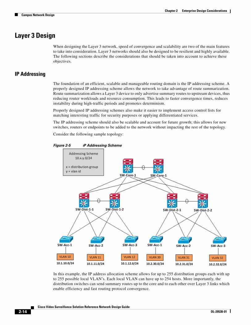
Figure 2-5 IP Addressing Scheme
In this example, the IP address allocation scheme allows for up to 255 distribution groups each with up to 255 possible local VLAN’s. Each local VLAN can have up to 254 hosts. More importantly, the distribution switches can send summary routes up to the core and to each other over Layer 3 links which enable efficiency and fast routing protocol convergence.
2-14Cisco Video Surveillance Solution Reference Network Design Guide
OL-29538-01

Chapter 2 Enterprise Design ConsiderationsCampus Network Design
IP Unicast Routing
Unicast routing could occur either at the access or distribution layer, with high-speed hardware-based switching reserved for the Campus core layer. In order for all participating hosts and routers to learn about destinations within the network, an interior gateway routing protocol must be configured. For most enterprise networks, the routing protocol of choice is either EIGRP or OSPF.
Enhanced Interior Gateway Protocol (EIGRP)
EIGRP is a classless, distance-vector routing protocol that is simple, scalable and fast. Classless meaning subnet masks are included in route advertisements, and distance-vector meaning it shares all its routing information but only to connected routes. The protocol is Cisco proprietary.
EIGRP provides multi-protocol support (IP, IPX, AppleTalk), sends some packets reliably (acknowledgements required) using Reliable Transport Protocol (RTP), uses hellos to discover neighbors and as a keep alive, and uses Diffusion Update Algorithm (DUAL) to select best paths and feasible failover routes. A combination of bandwidth and delay (by default, and optionally load, reliability and MTU) is used as the metric.
EIGRP achieves fast convergence through the concept of successors and feasible successors. A successor route has the lowest metric to the destination prefix and is installed in the routing table. A feasible successor has a higher feasible distance (metric to reach a destination) than the metric that its neighbor reports – that it, it satisfies the feasibility condition. The FS is stored in the topology table. Should an input event occur (new route, failed route), local computation is triggered, the result of which is that either the FS is promoted to be the successor or neighbors are queried for a valid route (i.e. the route goes active). EIGRP also offers MD5 authentication to protect routing updates between neighbors, as well as unequal-cost load balancing of traffic.
Open Shortest Path First (OSPF)
OSPF is a classless, link-state routing protocol that is fast and offers scalability to much larger networks. Link-state routing protocols advertise information only about directly connected links, but they share this information with all routers in their OSPF area. The protocol is an open standard developed by the IETF.
OSPF employs the use of routing domains (areas) to subdivide the network in order to introduce a two-level hierarchical framework that allows for scaling large and complex networks by containing the flow of routing protocol traffic and thus reducing the impact on CPU and memory resources. The two-level hierarchy consists of a backbone area (Area 0) and all other areas. If an OSPF design has multiple areas, the Area Border Routers (ABR’s) must connect to the backbone area in addition to its own attached area. If not physically feasible, an OSPF virtual link can be created that traverses a non-backbone area, to Area 0. Autonomous System Boundary Routers (ASBR’s) inject external routes, typically learned from an exterior protocol such as Border Gateway Protocol (BGP), into the OSPF process. All OSPF-speaking routers in the same area have the exact same topological database.
For multi-access topologies, broadcast (e.g. LANs) and non-broadcast (e.g. Frame Relay), a Designated Router (DR) and Backup Designated Router (BDR) are elected based on OSPF priority and/or router ID in order to form adjacencies with all participating routers (DROther) on a segment. A DR/BDR significantly lowers the number of neighbor relationships that need to be formed and as a result reduces the volume of link-state advertisements (LSA) flooded in the domain. In selecting best routes to a destination, OSPF uses a Shortest-Path First (SPF) calculation based on Dijkstra’s Algorithm. OSPF also provides equal-cost load balancing as well as plain-text and MD5 authentication.
2-15Cisco Video Surveillance Solution Reference Network Design Guide
OL-29538-01

Chapter 2 Enterprise Design ConsiderationsCampus Network Design
Considerations for EIGRP and OSPF
Both EIGRP and OSPF are very capable routing protocols; however, in determining which IGP to select for your network environment, there are several factors to take into account including, but not limited to:
EIGRP is cisco proprietary hence only works on Cisco devices, whereas OSPF is an open standard that will work on multi-vendor devices
Link-state routing protocols require greater CPU and memory resources relative to distance-vector protocols because they process routing information locally from all participating routers in the domain, not just connected routes
OSPF adapts well to larger, more complex networks due to its hierarchical architecture, fast convergence and varied network topology support; EIGRP is much simpler to deploy for relatively smaller networks with fast performance
EIGRP, as a distance-vector protocol, is more susceptible to routing loops and counting-to-infinity and as such must implement avoidance measures such as split-horizon, route-poisoning, and hold-down timers; OSPF is not subject to these routing issues
IP Multicast Routing
Multicasting involves sending packets to a designated group address. In the IP Video Surveillance environment, multicasting is used to transfer video traffic from a single source, the video endpoint, to the Video Surveillance Manager server.
Multicasting is useful for bandwidth consumption. Instead of sending multiple video streams to individual receivers, the same stream can be sent to a strategically placed rendezvous point on the network and all interested receivers can subscribe to the group to receive the stream. The current release of VSM does not support multicasting to client endpoints.
For multicast traffic to be properly routed, the network must be multicast-enabled. A multicast-enabled network is defined as a network where the following requirements are met:
• A defined set of IP addresses by which multicast groups are identified
• A mechanism by which hosts can join and leave multicast groups
• A routing protocol for efficient delivery of multicast traffic to group members
Class D IP addresses in the 224.x.x.x – 239.x.x.x range are reserved for multicast. Note that multicast addresses always begin with 1110 as the first four bits and are not subject to subnetting rules because these addresses are used to represent multicast applications, not hosts. Therefore, 28 bits (out of 32 in an IPv4 address) are available for a total of 228 (268,435,456) multicast groups possible. However, there are certain address ranges that have been reserved for specific use, for example 224.0.0.0/24 for link-local addresses. Of note is the reserved Administratively Scoped range of 239.0.0.0/8, defined in RFC2365. This range is designed to be used in private multicast domains and can be bound by filtering for these addresses at the network edge as well as other defined points where the multicast traffic should not traverse. It is therefore required to select multicast IP addresses, for IPICS in particular, from this address range.
Internet Group Management Protocol (IGMP)
When a router becomes aware of a multicast stream from a connected source, it must be able to determine whether any of its connected networks have hosts that want to join the group to receive the traffic. Once the host has joined the group, the router needs to have a way to query the network to determine if the host still wants to receive the multicast traffic, and when the host is done, it also needs a means to efficiently leave the group. The Internet Group Management Protocol (IGMP) carries out
2-16Cisco Video Surveillance Solution Reference Network Design Guide
OL-29538-01

Chapter 2 Enterprise Design ConsiderationsCampus Network Design
these functions. All participating hosts and routers must support IGMP to enable multicast sessions. IGMP is designed to be limited to the local link only – this is enforced by always setting the Time-To-Live (TTL) value in the encapsulated IP header to 1.
To join a group, a host sends a membership report message to the router. The router then identifies the host as a group member and allows it joins the session. Periodically, the router sends a query to determine if there are any remaining receivers in the subnet; group members receiving the query respond with a report sent to the group address. Note that only one membership report is sent in a group per subnet and it’s sufficient to inform the router that there are still members attached. To leave a group, a leave message is sent to the “All routers on subnet” group address (224.0.0.2).
IGMP snooping is a standards-based switching feature that allows for identification of hosts that request multicast traffic and therefore provide the ability to limit forwarding of group traffic to specific ports. This feature is enabled by default.
Multicast Distribution Trees
While unicast routing attempts to find and forward packets through the shortest path to a particular destination, multicast routing is concerned with finding and forwarding packets through the shortest path to the source, also known as reverse path forwarding (RPF). Routers along these forwarding paths keep the topology loop-free by implementing RPF checks on incoming traffic – the source IP address of an ingress packet on an interface is examined, then the unicast routing table is consulted to determine the next-hop interface as known by the router, and if they match then the packet is forwarded, otherwise it is dropped. In other words, the RPF check verifies that the packet arrived on the same interface that would be used if the router were to send traffic to the source.
These forwarding paths form the multicast distribution trees, and are of two types:
• Shortest Path Tree (SPT) or source-based tree – rooted at the source, with individual (S,G) pairs recorded for each multicast source within the group
• Root Path Tree (RPT) or shared tree – rooted at a router designated as the Rendezvous Point (RP), with only one (*,G) entry created for each group even if the RP has multiple upstream sources
Protocol Independent Multicast (PIM)
PIM is a routing protocol used to forward multicast traffic in an IP network. Other routing protocols exist such as Distance Vector Multicast Routing Protocol (DVMRP), Multicast Open Shortest Path First (MOSPF) and Core-Based Tree (CBT), however, only PIM is fully implemented in Cisco IOS and is thus the preferred protocol.
PIM exists in four variants:
• Dense Mode (PIM-DM) – source-based trees are built by sending traffic to every DM router in the network; if no hosts register on DM routers via IGMP, a prune message is sent back to the host (i.e. flood-and-prune method). Recommended where there’s a large number of recipients, who are located on every subnet (dense) and bandwidth is plentiful (e.g. on a LAN).
• Sparse Mode (PIM-SM) – shared trees are only built for and traffic forwarded to hosts that have sent an explicit join message to the RP. Note that PIM-SM can initiate a switch over from RPT to SPT, therefore potentially improving the packet forwarding efficiency with a shorter route to the source. Recommended where there are relatively small number of sources, with recipients sparsely distributed on the network and bandwidth is constrained (e.g. over a WAN).
2-17Cisco Video Surveillance Solution Reference Network Design Guide
OL-29538-01

Chapter 2 Enterprise Design ConsiderationsCampus Network Design
• Sparse-Dense Mode – provides support for operating in DM or SM on the same interface depending on the mode the multicast group is configured for. If a group has a known RP, then SM is selected, otherwise DM becomes operational. Interfaces must be configured in this mode when implementing group-to-RP mapping (automated RP discovery for SM) via Auto-RP. This is because RP mapping announcements are sent to all participating routers through dense mode flooding.
• Bidirectional (bidir-PIM) – an extension to PIM-SM that addresses its limitations in scaling to large numbers of sources. When multicast traffic is sent from the source, the first-hop leaf router doesn’t send Register messages to the RP so that it can join the source-specific tree as in SM; instead, it just forwards the multicast traffic upstream to the RP, through its RPF interface. In SM this action is not allowed as the RPF check only allows packets to be forwarded downstream, not upstream. To maintain a loop-free topology, a Designated Forwarder (DF) is elected on each segment to forward multicast traffic received on the network to the RP of the bidirectional group. As a result, any multicast traffic from any source is sent through the RP, loop-free, and with little overhead for multiple sources and recipients
Boundary DesignThere are main models for designing the boundary of the Access – Distribution block. Each method optimizes for different requirements and has caveats as discussed in the following sections.
Layer 2 Distribution
In this model, the Layer 2 – Layer 3 boundary is placed at the distribution layer, as illustrated in the figure below:
Figure 2-6 Layer 2 Distribution
The distribution switches are interconnected via a Layer 2 trunk. This topology is considered suboptimal due to the additional complexity and reliance on STP to maintain a loop-free topology. If a failure occurs, convergence times are relatively slower.
2-18Cisco Video Surveillance Solution Reference Network Design Guide
OL-29538-01

Chapter 2 Enterprise Design ConsiderationsCampus Network Design
In this topology it’s also important to ensure that the HSRP primary node and STP root bridge are defined on the same switch so that as VLAN’s are load-balanced, the inter-distribution link is not used consistently for transit traffic.
This topology is typically used when VLAN’s are spanned across access switches. Cisco recommends that VLAN’s should not be spanned across switches whenever possible, particularly when a first-hop router protocol such as HSRP is deployed. This topology could lead to asymmetric routing which can cause unicast flooding whenever traffic is sent to a receiver and this is due to the difference in the aging timers of the Content Addressable Memory (CAM) table and Address Resolution Protocol (ARP).
Layer 3 Distribution
In this model, the Layer 2 – Layer 3 boundary is also placed at the distribution layer, but the inter-distribution link is routed. The following figure illustrates this topology:
Figure 2-7 Layer 3 Distribution
VLAN’s do not span across switches, but as in the previous model, the STP root is aligned with the HSRP primary. All links on the distributed switches are in the forwarding state with HSRP providing the first-hop redundancy.
This topology is considered optimal and provides the highest availability. At the access layer, Layer 2 switches can be used which saves on cost. The inter-distribution link allows for route summarization between the distribution switches.
2-19Cisco Video Surveillance Solution Reference Network Design Guide
OL-29538-01

Chapter 2 Enterprise Design ConsiderationsCampus Network Design
Layer 3 Access
In this model, the Layer 2 – Layer 3 boundary is established at the access switch level, as illustrated below:
Figure 2-8 Layer 2 Access
VLAN’s do not span the access switches. Since a routing protocol is required on the switches, first-hop redundancy protocols like HSRP are not required. This design also supports equal-cost load balancing on all Layer 3 switch links.
This design is considered optimal because it’s relatively easier to implement and achieves the fastest sub-second convergence due to the routing protocol convergence algorithms. However, multilayer switches will be required for all access switches, which can drive up cost and may be prohibited due to the existing architecture.
2-20Cisco Video Surveillance Solution Reference Network Design Guide
OL-29538-01

Chapter 2 Enterprise Design ConsiderationsCampus Network Design
Virtual Switching System
As an alternative to installing two independent chassis at the distribution layer for the datacenter network, the Virtual Switching System can be deployed.
VSS 1440 is a system virtualization technology that combines a pair of Catalyst 6500 switches, deployed in the datacenter, into a single logical network segment, as shown in the comparative illustration below:
Figure 2-9 Virtual Switching System
The benefits of VSS are that the need for first-hop redundancy protocols, like Virtual Redundancy Routing Protocol (VRRP) and Hot Standby Routing Protocol (HSRP), is negated since the chassis-pair are pooled and operate as a single network node. Only one IP address is required per VLAN.
Also, the need for Spanning-Tree Protocol (STP) is negated as port channels on uplinks connect to a single device, forming a loop-free topology. Access switches can connect to and form a port channel between two different distribution switches through the use of a multi-pathing technology – Multichassis Etherchannel (MEC).
A caveat to note with VSS designs is the fact that they must be deployed in pairs; it’s not possible to add a third switch to a VSS to increase availability.
2-21Cisco Video Surveillance Solution Reference Network Design Guide
OL-29538-01

Chapter 2 Enterprise Design ConsiderationsCampus Network Design
2-22Cisco Video Surveillance Solution Reference Network Design Guide
OL-29538-01

Cisco Video SurvOL-29538-01
C H A P T E R 3
Network Video ConsiderationsThere are various considerations to be taken into account when transporting video over an IP network. This section examines compression techniques as well as factors that impact overall video stream quality.
Video CompressionVideo endpoints consume a large amount of raw data from the scene in their field of view. This raw data in its present form is unsuitable for transport over the network and for storage by the Media Server due to its large footprint, so therefore must be intelligently compressed before transmission to the receiver.
Compression refers to the reduction of redundant and irrelevant signal data in a video stream to lower the network bandwidth and storage requirements.
Compression AlgorithmsWhen compressing raw data, video codecs strive to strike a balance between intelligently reducing the size of output data, while still maintaining image quality. There are three main algorithms or techniques that are widely used for compression of video streams:
Chroma subsampling
This technique involves the reduction of color detail (chroma) in a video frame, in favor of variations in its brightness (luma) levels. This approach takes advantage of the fact that the human eye is comparatively less perceptive of subtle changes to color richness, in contrast to changes in the amount of light in the image.
Depending on the field of view, this technique has the potential to achieve relatively modest reductions in the average frame size.
Spatial compression
This technique involves the reduction of redundant data within a video frame, also referred to as intra-frame coding. This technique leverages the property that pixels in a video frame are closely related to their neighbors.
3-1eillance Solution Reference Network Design Guide

Chapter 3 Network Video ConsiderationsVideo Compression
Therefore, a reduction in the number of pixels within a frame that contain very similar data, has the potential to result in an appreciable 20 – 70% reduction in average frame sizes, depending on the scene in the field of view.
Temporal compression
This technique involves the reduction of redundant data between successive frames, also referred to as inter-frame coding. This technique exploits the property that, in general, sequential frames in a group of pictures (GOP) contain areas with redundant data quite similar to those in preceding frames.
With this algorithm, average frame sizes can potentially be drastically reduced by 50 – 80% in scenes with little to no motion as only the portions of the scenes that have changed are transmitted in subsequent frames. In scenes with medium to high complexity, the gains in compression are capped as more data must be transmitted in subsequent frames to represent scene changes in the field of view.
Group of PicturesA Group of Pictures (GOP) is a sequence of frames in an encoded video stream. There are three types of video frames as illustrated in Figure 3-1
Figure 3-1 Sequence of Frames in an Encoded Video Stream
Intra Frames
These frame types consist of a complete picture, representing the complete scene in a field of view. The image is coded without reference to other frames in the GOP. They are also referred to as I-frames. Each GOP structure starts with this frame type. The I-frame interval is typically not directly configurable – the Media Server programmatically determines this value based on other stream options. I-frames are used with both spatial and compression algorithms.
Predictive Frames
These frames are also referred to as P-frames. These frame types represent only the data within a field of view that has changed. They are coded with reference to the preceding I-frame or P-frame in the GOP. P-frames are used with temporal compression.
Bidirectional Predictive Frames
B-frames utilize either the previous and next I-frame or P-frame as reference points for motion compensation. B-frames are not as commonly implemented in compression due to increased latency associated with the compensation prediction, which can potentially be a drawback for real-time video delivery.
3-2Cisco Video Surveillance Solution Reference Network Design Guide
OL-29538-01

Chapter 3 Network Video ConsiderationsVideo Compression
Video CodecsRaw video data is encoded into a video stream in order to allow for efficient network and system resource utilization. At the receiver, the data needs to be decoded for consumption by video clients. This process is implemented using codecs.
The following codecs are commonly used in VSM for camera configuration:
Motion JPEG
Motion JPEG (MJPEG) consists of a series of individual JPEG images. These images are coded as individual I-frames therefore every frame that is produced by the codec is a complete reference frame that is representative of the field of view.
Figure 3-2 illustrates a typical MJPEG stream profile:
Figure 3-2 Typical MJPEG Stream Profile
The main advantage with this encoded format is that it provides a measure of robustness in stream delivery. Any occurrence of packet loss in the network flow does not adversely affect subsequent frames, since each frame is a complete image. In other words, if a frame is lost, the next frame clears up any residual effects from the previous image (e.g. a frozen image on screen), since it has no missing information.
The main drawback with MJPEG is that it has higher bandwidth and storage requirements. Average frame sizes are relatively large due to the fact that it uses spatial compression that realizes fairly modest compression ratios within frames.
3-3Cisco Video Surveillance Solution Reference Network Design Guide
OL-29538-01

Chapter 3 Network Video ConsiderationsVideo Compression
MPEG-4
Video data encoded in this MPEG-4 (strictly MPEG-4 Part 2) format is composed of both I-frames and P-frames in its GOP structure. Since this format uses temporal compression, in general bandwidth and storage utilization is much lower than MJPEG, although this is also dependent on the amount of motion occurring in the scene.
H.264
This encoding format, also referred to as MPEG-4 Part 10 or AVC, is based on the MPEG-4 standard but achieves much higher predictive compression ratios when compared to both MJPEG (up to 80%) and MPEG-4 Part 2 (up to 50%). This format delivers high compression at high bit rates, while resulting in higher quality streams. This codec uses temporal compression.
Figure 3-3 illustrates a typical H.264 stream profile, showing I-frames and P-frames:
Figure 3-3 Typical H.264 Stream Profile
Note The relative bandwidth and storage efficiencies are largely dependent on the scene complexity – high complexity scenes result in very modest to no resource efficiencies when compared to MJPEG encoded data under similar conditions, because each frame (I-frames and P-frames) will be coded essentially as
3-4Cisco Video Surveillance Solution Reference Network Design Guide
OL-29538-01

Chapter 3 Network Video ConsiderationsVideo Compression
complete frames in order to represent the scene changes in the field of view. However, where these conditions are not sustained over long periods of time, H.264 turns out to be far superior as an encoding format.
The main drawback with H.264 is the higher hardware (GPU, CPU, memory) and software (DirectX and other software components) resource requirements to perform the encoding and decoding operations. This is especially pronounced at the client endpoint, as it will impact the total number of H.264 streams that can be rendered at any point in time.
Stream QualityThe perception of the quality of a stream to end users is affected by various factors as outlined below:
Resolution
Stream resolution describes the total number of pixels in each horizontal and vertical (x/y) dimension. The following table defines some of the most common resolutions in use today:
Table 3-1 Common Stream Resolutions
Format Resolution
Analog QCIF 176 x 120
CIF 352 x 240
4CIF 704 x 480
D1/480p 720 x 480
HDTV 720p 1280 x 720 (0.9 MP)
1080p 1920 x 1080 (2.1 MP)
Digital VGA 640 x 480
SXGA 1280 x 1024 (1.3 MP)
EXGA 1400 x 1050 (1.5 MP)
UXGA 1600 x 1200 (1.9 MP)
WUXGA 1920 x 1200 (2.3 MP)
QSXGA 2560 x 2048 (5.2 MP)
The stream resolution directly influences the data-carrying capacity of each frame – the higher the resolution, the larger the amount of video data that can be encoded and transmitted resulting in a “richer” and sharper image quality. For example, 1080p resolution has six times as many pixels per frame as compared to D1 resolution.
Consequently, higher resolutions are typically paired with higher bitrate settings in a stream profile in order to allow the codec to produce compressed data at a rate that maintains the same perceived quality as at lower profiles. The corollary is that if comparatively low bitrate settings are used with high resolutions, the image may appear to be of lower quality (e.g. grainy or blurry), since the codec cannot not produce enough data to be represented by all available pixels as required to maintain the same quality.
3-5Cisco Video Surveillance Solution Reference Network Design Guide
OL-29538-01

Chapter 3 Network Video ConsiderationsVideo Compression
Processing of streams at higher resolutions is resource intensive thus imposes higher hardware requirements particularly at the client since there is more pixel data to process per frame per unit time. Therefore, in order to perform near real-time processing, higher-end GPU, CPU and memory is required.
Lower stream resolutions conversely have lower infrastructure resource requirements but also typically result in relatively lower quality images. The choice of resolution will largely depend on the respective use case.
Bit Rate
The stream bitrate describes the data transfer rate produced by a codec for transmission to receivers. A stream profile can be defined with either of the modes below:
• Variable Bit Rate (VBR) mode – the data transfer rate is automatically varied by the codec to match a desired image quality. The image quality is defined by the quantization level. In a complex scene, the amount of data required to fully represent the field of view is typically higher than in less complex scenes where there’s little to no motion activity present.
• Constant Bit Rate (CBR) mode – the image quality is varied to match the target data transfer rate. In this case the data transfer rate is fixed so the encoder has to produce sufficient data to match the mean target rate, typically with a small standard deviation. With CBR, on average the same amount of data is produced always.
VBR is generally used in instances where image quality is fixed and is desired to be maintained at that level regardless of the scene complexity. CBR is generally used in instances where determinism in the bandwidth utilization of video streams on the network is desired.
Frame Rate
The frame rate refers to the number of individual encoded video frames transmitted per unit time.
As a primary function, the frame rate directly influences the visual perception of continuous motion in a scene (i.e. the smoothness) as observed by the end user. High frame rates (generally above 25 fps) produce the best perception of smooth video, while low frame rates (generally below 5 fps) cause the eye to perceive the apparent discontinuity in the rendering of the image stream.
In addition, the frame rate of a video stream indirectly influences its network bandwidth utilization. When VBR mode is selected, the bit rate is automatically adjusted to match a desired quality or quantization level, which results in the respective variation in frame rate and average frame size as the amount of encoded data increases or decreases based on the scene complexity.
3-6Cisco Video Surveillance Solution Reference Network Design Guide
OL-29538-01

Chapter 3 Network Video ConsiderationsVideo Compression
In CBR mode, the frame rate does impact bandwidth but to a smaller extent than in VBR mode. Increasing the frame rate may result in an increase in data transferred but does not exceed the target bitrate. In Figure 3-4 of an H.264 stream at 768 Kbps CBR, reducing the frame rate by 80% from 30fps to 5fps, only resulted in a 30% drop in bandwidth, all else remaining constant.
Figure 3-4 H.264 Frame Rate Reduction Example
However, higher frame rates will also impose additional processing overhead due to the increased number of frames in the same time period at the client endpoint. Therefore, when choosing stream frame rates, pay close attention to the client compute resources available to ensure an appropriate viewing experience is achieved for the environment.
Quantization Factor
The quantization level defines the compression level used by a codec to convert raw video data into an encoded format. Typically, the reference scale varies by manufacturer e.g. 1-10, 0-100, low/medium/high, etc. Lowering the quantization level on the respective reference scale increases the compression level and lowers the image quality.
Lowering the image quality is appropriate in situations where bandwidth or storage resources are limited, and the need for high quality images is not a top priority for users in the environment.
3-7Cisco Video Surveillance Solution Reference Network Design Guide
OL-29538-01

Chapter 3 Network Video ConsiderationsVideo Compression
Figure 3-5 shows two stream profiles from the same camera, both H.264 15fps VBR, with different quantization settings – “low” and “very high”:
Figure 3-5 Quantization Settings For Two Stream Profiles
Since the quantization level lets one set the desired image quality level, it is only directly configurable when VBR mode is used. When CBR mode is used, the quantization level is varied automatically by the codec compression algorithm in order to match the target bit rate. Therefore, the direct programmability of quantization and CBR mode are mutually exclusive.
3-8Cisco Video Surveillance Solution Reference Network Design Guide
OL-29538-01

Cisco Video SurvOL-29538-01
C H A P T E R 4
Media Flow ConsiderationsA media flow refers to the session that is established for media delivery between a source host producing the video and a destination host receiving the video, using an agreed-upon transport protocol and communicating between two established ports.
This chapter examines these data flows, protocols mechanics and the interaction between the servers and endpoints on the network
Data Flow Once a stream profile, based on options such as resolution, bitrate, frame rate, quality, etc., has been established, the media server can initiate the stream request for video endpoints that are in the “Enabled” state. The media server logs into the video endpoint device and applies the configuration settings, and once completed successfully, the requested video data begins streaming to the server.
Figure 4-1 illustrates the high-level:
Figure 4-1 Media Server Data Flow and Components
All device management and streaming operations from particular camera endpoints are managed by unique umsdevice processes on the server. The video stream from the endpoint is then made available to internal processes that consume this data – such as the recording process, analytics or can be immediately served out live to client endpoints through the MediaOut subsystem.
Each client request for streaming of live or recorded video is managed by a MediaOut process on the server.
4-1eillance Solution Reference Network Design Guide

Chapter 4 Media Flow ConsiderationsData Flow
When a client requests to view a particular stream, the server establishes the session to the client endpoint and delivers the stream as it is available.
Figure 4-2 illustrates the data flow sequence:
Figure 4-2 Data Flow Sequence
Step 1 The end user will first be required to successfully authenticate their log-in credentials with the Operations Manager (OM) server, using the web or desktop client application.
Step 2 Following a successful login-in, the client application retrieves and displays the list of configured cameras in the OM database that the user is authorized to access.
Step 3 When a particular stream is selected for viewing by the end user, the OM server identifies the host Media Server (MS) that manages the requested endpoint device and redirects the client to establish the media session directly with that MS.
Step 4 Once established, if the camera is in a streaming state or the recording is available, the live or recorded media stream is served to the client application.
Note The connection between the server and camera endpoint is always streaming, unless the stream is optimized through the use of the economical streaming feature that only streams live from the video endpoint when requested by client endpoints.
4-2Cisco Video Surveillance Solution Reference Network Design Guide
OL-29538-01

Chapter 4 Media Flow ConsiderationsMedia Transport Protocols
Media Transport ProtocolsIP video surveillance traffic is delivered from sources to receivers using a set of standards-based protocols that govern the initialization, transfer and teardown of media flows on the network. This section describes these protocol mechanics.
Real Time Streaming Protocol (RTSP)RTSP is an session-layer protocol that is used to control the delivery of real-time streaming audio and video content over IP networks. RTSP is typically implemented over TCP, listening on the well-known port 554. Video payload does not actually use RTSP for delivery; rather, Real-Time Protocol (RTP) is used for this purpose.
RTSP maintains state between clients and servers when media sessions are active in order to correlate RTSP requests with a video stream. The simplified finite-state machine is illustrated in Figure 4-3:
Figure 4-3 Simplified Finite-state Machine
The RTSP state machine uses the following main protocol directives to control the multimedia session:
OPTIONS
After establishing the TCP connection to the server on port 554, the client issues an OPTIONS command to request the list of supported options. The server then responds with a list of all the options that it supports e.g. DESCRIBE, SETUP, TEARDOWN, etc.
DESCRIBE
The client issues a DESCRIBE command to notify the server the URL of the media file that it’s requesting. Figure 4-4 illustrates the request made from the VSM server (acting as the RTSP client) to a Cisco 2611 IP camera:
4-3Cisco Video Surveillance Solution Reference Network Design Guide
OL-29538-01

Chapter 4 Media Flow ConsiderationsMedia Transport Protocols
Figure 4-4 DESCRIBE Command
The IP camera then responds with a description of the stream, as shown in Figure 4-5:
Figure 4-5 Stream Description
The parameters of the stream are defined in Session Description Protocol (SDP) format (Figure 4-6):
Figure 4-6 Stream Parameters
SETUP
The client issues a SETUP command to indicate to the server the transport mechanisms to be used for the session.
Figure 4-7 illustrates the client request:
Figure 4-7 Client Request
4-4Cisco Video Surveillance Solution Reference Network Design Guide
OL-29538-01

Chapter 4 Media Flow ConsiderationsMedia Transport Protocols
In this example, for media delivery the VSM server will use UDP port 16102 for RTP and 16103 for RTCP. The IP camera then responds, acknowledging the client’s port assignment and indicating its own (5002 and 5003, respectively) as well as a session ID, as illustrated in Figure 4-8:
Figure 4-8 IP Camera Response
PLAY
Once the client is ready to begin receiving video data, it issues a PLAY request to the server (Figure 4-9):
Figure 4-9 PLAY Request
PAUSE
If a client wants to momentarily stop the delivery of video traffic, the PAUSE request can be issued. This directive has the effect of stopping the media stream without freeing server resources. Once the PLAY command is re-issued, the stream resumes the data flow.
TEARDOWN
If a client wants to permanently stop receiving video traffic, the TEARDOWN request is issued (Figure 4-10):
Figure 4-10 TEARDOWN Request
4-5Cisco Video Surveillance Solution Reference Network Design Guide
OL-29538-01

Chapter 4 Media Flow ConsiderationsMedia Transport Protocols
Real-Time Transport Protocol (RTP)RTP is a transport-layer protocol that defines the set of conventions used to provide end-to-end network transport capabilities for transmission of real-time data, such as voice and video. RTP utilizes either UDP or TCP for transporting video data across the network.
RTP always selects even ports at the transport layer for both servers and clients. As described in the previous section, during set up of the RTSP session the client first indicates its destination ports for receiving video and then the server acknowledges and responds with the UDP ports that it will be using to send the RTP data. Note that all RTP traffic is unidirectional – from source to receiver only.
The RTP packet contains three important fields:
• Timestamp – used for ordering of incoming video packets for correct timing during playback
• Sequence number – used to uniquely identify each packet in a flow for packet loss detection
• Source Synchronization – used to uniquely identify the source of a media stream
Figure 4-11 illustrates the composition of the RTP packet:
Figure 4-11 RTP Packet
Real Time Control Protocol (RTCP)RTCP is a protocol used in conjunction with RTP for reporting on stream-quality information to the server. RTCP is bidirectional and uses UDP as the transport protocol.
RTCP always selects an odd-numbered port, and is always one port higher than the UDP port used for RTP. In general, RTCP accounts for less than 5% of stream traffic.
4-6Cisco Video Surveillance Solution Reference Network Design Guide
OL-29538-01

Chapter 4 Media Flow ConsiderationsFlow Characterization
Flow CharacterizationRTP media flows could either use UDP or TCP as the transport protocol of choice. This section describes the considerations for both approaches.
Video Endpoint-to-Media Server FlowMedia delivery between video endpoints and the media server by RTP could either be accomplished using UDP or TCP as the transport protocol.
It is important to note that the availability either or both protocols for use when defining the stream profile in the media server is entirely dependent on the capabilities of the camera driver built for a particular device model. These capabilities are in turn influenced by the API provided by the device manufacturer. Therefore, the sockets used for session establishment and media streaming are device specific
The following sections examine the protocol mechanics of both methods, as well as techniques for determining sockets that are being used by the VSM server to connect to IP video and client endpoints.
RTP over UDP
When a camera is configured in VSM to stream over UDP, the traffic patterns illustrated inFigure 4-12 are initiated:
Figure 4-12 UDP Traffic Patterns
The management plane is a logical path in the network communication architecture that handles all device management traffic between the endpoints and the VSM server, and between VSM servers. In addition, this plane coordinates the function of the other planes. Traffic is transferred and encrypted over
4-7Cisco Video Surveillance Solution Reference Network Design Guide
OL-29538-01

Chapter 4 Media Flow ConsiderationsFlow Characterization
Secure HTTP. The Openwire protocol is used by the ActiveMQ broker for real-time messaging between VSM servers and between VSM servers and the SASD client. Stomp protocol is a simpler, lightweight alternative to Openwire and is used between the VSOM server and the web client.
At the control plane, RTSP is used to provide signalling for the media streams. RTSP is implemented at the segments between both endpoints. The source port at the sender is always TCP 554; the destination port on the VSM server and at the client endpoint is negotiated during the TCP connection establishment process.
At the data plane, the source and destination ports are both negotiated during the RTSP SETUP process. The source ranges are defined and are configurable at the video endpoint web interface and at the media server console, respectively. The media server UDP destination port range is statically defined to be in the 16000 – 19999 range and is not configurable. Note that since RTP always transmits on even ports, at any point in time an implied maximum of 2000 camera streams can be supported per media server. However, this value is beyond the supported threshold at the time of this writing (250 Mbps stream IO). Consult the current datasheets for up to date information on configuration maximums.
The implication of streaming RTP over UDP is that if the video traffic needs to traverse a firewall, all ports in the range must be allowed for all video endpoints if the flow is in the outside-to-inside direction. If the flow is inside-to-outside, a stateful firewall can be used to allow back returning control and management traffic to the endpoint.
Client endpoints behind a firewall pose an even greater challenge since the UDP ports are assigned dynamically so it’s difficult to determine which ports to open. In such a case, it would be recommended to create a VPN tunnel to exchange traffic between the VSM’s server network and the client endpoint.
4-8Cisco Video Surveillance Solution Reference Network Design Guide
OL-29538-01

Chapter 4 Media Flow ConsiderationsFlow Characterization
The packet capture in Figure 4-13 illustrates the session establishment and video streaming over UDP:
Figure 4-13 UDP Session Establishment and Video Streaming
In the figure above, the VSM server (10.103.0.8) logs into the camera (10.200.42.12) over a HTTPS (TCP/443) connection and completes the handshake. The stream negotiation process over RTSP (TCP/554) is initiated and then subsequently RTP streaming is initiated over UDP/16102 on the Media Server and UDP/5002 on the video endpoint.
In order to find out which ports have been opened for a particular camera stream on the Media Server, first obtain the associated process ID and then retrieve the open sockets a shown below (note: applies to VSM 7.x releases):
media-server:~# lsof –c umsdevice –[email protected] –a | awk ‘{print $2}’PID24160
media-server:~# lsof –p 24160 –i –a –n –PCOMMAND PID USER FD TYPE DEVICE SIZE NODE NAME umsdevice 24160 nobody 13u IPv4 44305817 TCP 10.103.0.8:57824->10.200.42.12:554 (ESTABLISHED)umsdevice 24160 nobody 14u IPv4 44305818 UDP *:16102umsdevice 24160 nobody 15u IPv4 44305819 UDP *:16103
4-9Cisco Video Surveillance Solution Reference Network Design Guide
OL-29538-01

Chapter 4 Media Flow ConsiderationsFlow Characterization
RTP over TCP
When a camera is configured in VSM to stream over TCP, the traffic patterns illustrated in Figure 4-14 are initiated:
Figure 4-14 TCP Streaming Traffic Patterns
The management and control plane are identical when transporting data over UDP and TCP.
At the data plane, RTP is interleaved onto the existing RTSP connection, which means that the RTP stream is encapsulated and now transmitted over the same TCP connection that is being used for RTSP. As a result, only one port is utilized to transport all media flows. This property is useful in environments where the media flow needs to traverse a firewall – only one deterministic port is required to be opened for the RTP traffic to go through. The server also interleaves RTCP messages over the TCP connection.
Interleaving is enabled whenever a camera stream is configured for TCP. Cisco recommends that the TCP option should only be used in the case where firewalls exist in the end-to-end path between servers and endpoints; in all other instances, UDP should be used to allow for faster delivery of real-time video traffic.
4-10Cisco Video Surveillance Solution Reference Network Design Guide
OL-29538-01

Chapter 4 Media Flow ConsiderationsFlow Characterization
The following packet capture illustrates the session establishment and video streaming over TCP (Figure 4-15):
Figure 4-15 TCP Session Establishment and Video Streaming
The figure above (Figure 4-15) shows the connection establishment to the IP camera, this time over HTTP (TCP/80). The RTSP (TCP/554) connection is established and the RTP video stream is interleaved over the same RTSP connection; that is, over TCP 554.
Note that in some instances, some camera models may establish the management and data plane over HTTP as opposed to over RTSP. In effect, the video stream is transmitted over TCP/80. In particular, this behavior is true for Cisco 29xx series cameras, as illustrated in the output below of a Cisco 2911 PTZ camera with IP 10.101.0.10:
media-server:~ # lsof [email protected] -n -PCOMMAND PID USER FD TYPE DEVICE SIZE NODE NAMEumsdevice 24160 nobody 9u IPv4 44302980 UDP 10.100.21.20:59429->10.101.0.10:30001
4-11Cisco Video Surveillance Solution Reference Network Design Guide
OL-29538-01

Chapter 4 Media Flow ConsiderationsFlow Characterization
umsdevice 24160 nobody 11u IPv4 44304849 TCP 10.100.21.20:41422->10.101.0.10:80 (ESTABLISHED)
Media Server-to-Client Endpoint FlowMedia delivery between the media server and the client endpoint, regardless of the connectivity profile between the video endpoint and media server, is accomplished by interleaving the RTP stream over the RTSP session on TCP/554. Consequently, for each client connection to the server, a single media stream session is initiated.
Figure 4-16 illustrates the flow pattern:
Figure 4-16 Media Server-to-Client Flow Pattern
4-12Cisco Video Surveillance Solution Reference Network Design Guide
OL-29538-01

Chapter 4 Media Flow ConsiderationsFlow Characterization
Figure 4-17 illustrates the protocol mechanics in session establishment between the client and the server:
Figure 4-17 Media Server-to-Client Session Establishment
The first three packets illustrate the TCP three-way handshake, then RTSP protocol messages describing and establishing connectivity. Note that once the stream starts flowing after the PLAY command, the dynamic RTP connection is streamed over the RTSP port TCP/554 on the server to the client at TCP/62143.
All outbound streaming from the media server is handled by the MediaOut subsystem. To examine which ports have been opened for a particular streaming request from the client to the server, the following commands can be executed:
media-server:~ # lsof -c MediaOut -i -a -n -P | grep ESTMediaOut 23519 root 7u IPv4 44957697 TCP 10.100.21.20:554->10.1.99.3:62143 (ESTABLISHED)
4-13Cisco Video Surveillance Solution Reference Network Design Guide
OL-29538-01

Chapter 4 Media Flow ConsiderationsFlow Characterization
4-14Cisco Video Surveillance Solution Reference Network Design Guide
OL-29538-01

Cisco Video SurvOL-29538-01
C H A P T E R 5
Network Services ConsiderationsIn designing the IP Video Surveillance network, there are various essential IP services that are integral in supporting the solution. These services are described below:
• Network Time Protocol, page 5-1
• Dynamic Host Control Protocol, page 5-2
• Simple Network Management Protocol, page 5-5
Network Time ProtocolNTP is an internet standard protocol that is used to synchronize time on network machines to a defined authoritative reference clock. Clock sources are organized in a hierarchical system of levels, where each level is referred to as a stratum. The stratum number determines how many NTP hops the machine is away from the authoritative time source.
Time synchronization is very important in an IP Video Surveillance environment because activities such as recording, grooming, event correlation and troubleshooting are dependent on having correct time across all participating servers and endpoints.
Among nodes on the network, time synchronization is also important in validating that predetermined Service Level Agreements (SLA’s) for the solution are being met. Without correct time synchronization, network latency and jitter cannot be accurately determined.
Cisco recommends that all client endpoints, video endpoints, network nodes, media servers and operations manager servers be configured to synchronize to a common NTP master server.
The NTP master could be configured on a Layer 3 IOS device on the network that is used for management, or on an external time server that is reachable by all devices in the subnetwork.
Layer 3 IOS devices can be configured to act as an NTP master as follows:
!! Set the time zone information in global configuration mode!clock timezone PST -8clock summer-time PDT recurring!! Set the hardware calendar configuration!clock calendar-validntp update-calendar!! Ensure the correct time is set in privilege exec mode
5-1eillance Solution Reference Network Design Guide

Chapter 5 Network Services ConsiderationsDynamic Host Control Protocol
!sh clock!! If not, then set the clock time, for example to 1:35pm 10th October 2012!clock set 13:35:00 10 OCT 2012!! Define the master time server! ntp master!! Set the interface from which NTP packets are sourced to the loopback address; note that! the loopback address needs to have been previously defined!ntp source loopback0!
NTP authentication can also be configured but one would need to ensure that all devices that will synchronize to this time server can support authentication, otherwise the synchronization will fail.
It is also important to take into account that if the current system time on a device that is not synchronized differs significantly from the time server, NTP synchronization will not succeed. As a precaution, it is advisable to manually set the system time on the client device, and then enable NTP synchronization.
Dynamic Host Control ProtocolDHCP is an internet protocol that provides a framework for the automatic assignment of reusable IP addresses, as well as passing other network configuration attributes, to a client on a network. For the IP Video Surveillance solution, these additional attributes include:
• Default gateway address
• DNS server address(es)
• VSM media server address(es)
DHCP is important in the IP Video Surveillance environment because it cuts down deployment times for IP video endpoints. Instead of having to manually configure each camera with required IP parameters, they are automatically discovered and assigned.
The Medianet architecture, implemented in IP video endpoints through the embedded Media Services Interface (MSI), allows for discovery of preconfigured media servers on the network for subsequent auto-registration to VSM. The list of media servers is supplied to the IP video client through the DHCP option 125.
As previously discussed, Cisco recommends the use of local VLAN’s as opposed to spanning VLAN’s across the network domain. For ease of management, most organizations typically configure one DHCP server to service multiple subnets. Since initial DHCP messages are broadcast on the subnet, and Layer 3 devices do not forward broadcasts as they form the boundary of the broadcast domain, DHCP relay agents will need to be configured in order to forward the messages to the DHCP server on a different subnet.
5-2Cisco Video Surveillance Solution Reference Network Design Guide
OL-29538-01

Chapter 5 Network Services ConsiderationsDynamic Host Control Protocol
The following illustration shows the sequence of events when a DHCP client connects to the network:
Figure 5-1 DHCP Client Connection
1. The video endpoint sends a DHCPDISCOVER message as a broadcast to all subnets (source IP 0.0.0.0, destination IP 255.255.255.255) on UDP/67 (BootP server) to try reach a DHCP server on the network
2. The Layer 3 device that acts as the DHCP relay agent (in this case a distribution node) intercepts the broadcast message and generates a new unicast DHCP message, inserting the IP address of the interface on which the relay agent is configured in the gateway address (giaddr) field of the DHCP packet, and then forwards the request to the designated DHCP server on the network
3. Upon receiving the request, the DHCP server takes note of the giaddress field and examines the configured DHCP pools to determine which subnet to allocate IP addresses from. The server then responds with a DHCPOFFER as a UDP/67 packet that contains the configuration parameters, or options. These options include:
a. IP address (Option 50)
b. Subnet mask (Option 1)
c. Default gateway (Option 3)
d. Lease duration (Option 51)
e. DNS server (Option 6)
f. Vendor-identifying vendor-specific (Option 125)
4. The DHCP relay agent receives the offer and forwards it to the DHCP client as a unicast message on UDP/68. The DHCPOFFER is not a guarantee that the specified address will be allocated, but the server will typically reserve the assignment until the client responds
5. Upon receiving the DHCPOFFER, the IP video endpoint sends a formal request for the offered address in a DHCPREQUEST message. This is a broadcast request to notify any other DHCP servers that received the initial DHCPDISCOVER message and may have responded so that they can reclaim their assigned offers.
6. Finally the DHCP server upon receiving the formal request, allocates the IP address and sends a DHCPACK message back to the client
5-3Cisco Video Surveillance Solution Reference Network Design Guide
OL-29538-01

Chapter 5 Network Services ConsiderationsDynamic Host Control Protocol
The DHCP relay agent can be configured as shown below:
!! Configure a device as a relay agent to forward DHCP messages to the 10.102.0.100 DHCP server!interface vlan42 ip address 10.200.42.1 255.255.255.0 ip helper-address 10.102.0.100!
The IOS DHCP server can be configured as shown below:!! In global configuration mode, exclude the IP address of the default router ! and any other static hosts, then configure the address pools! If multiple address ranges will be required, configure a top-level pool! from which common attributes will be inherited! The IP address of the media server can also be passed in Option 125! Option is in hex format: 0000.0009.0b14.0901.<vsm-ip-in-hex>.0050.0001! In this example, the VSM server’s IP is 0a64.1516 (10.100.21.22)!ip excluded-address 10.200.42.1!ip dhcp pool 0 network 10.0.0.0 255.0.0.0 dns-server 10.102.0.50 domain-name cisco.com!ip dhcp pool 1 network 10.200.42.0 255.255.255.0 default-router 10.200.42.1 option 125 hex 0000.0009.0b14.0901.0a64.1516.0050.0001!
The following is sample output of the DHCP packet and event exchange between an IP camera and IOS DHCP server:
17w1d: DHCPD: DHCPDISCOVER received from client 0100.22bd.dc78.19 on interface Vlan101.17w1d: DHCPD: using received relay info.17w1d: DHCPD: Sending notification of DISCOVER:17w1d: DHCPD: htype 1 chaddr 0022.bddc.781917w1d: DHCPD: interface = Vlan10117w1d: DHCPD: class id 436973636f2049502043616d65726117w1d: DHCPD: out_vlan_id 017w1d: DHCPD: DHCPOFFER notify setup address 10.101.0.21 mask 255.255.255.017w1d: DHCPD: Sending DHCPOFFER to client 0100.22bd.dc78.19 (10.101.0.21).17w1d: DHCPD: no option 12517w1d: DHCPD: Check for IPe on Vlan10117w1d: DHCPD: creating ARP entry (10.101.0.21, 0022.bddc.7819).17w1d: DHCPD: unicasting BOOTREPLY to client 0022.bddc.7819 (10.101.0.21).17w1d: DHCPD: Reload workspace interface Vlan101 tableid 0.17w1d: DHCPD: tableid for 10.101.0.1 on Vlan101 is 017w1d: DHCPD: client's VPN is.17w1d: DHCPD: DHCPREQUEST received from client 0100.22bd.dc78.19.17w1d: DHCPD: Sending notification of ASSIGNMENT:17w1d: DHCPD: address 10.101.0.21 mask 255.255.255.017w1d: DHCPD: htype 1 chaddr 0022.bddc.781917w1d: DHCPD: lease time remaining (secs) = 60480017w1d: DHCPD: interface = Vlan10117w1d: DHCPD: out_vlan_id 017w1d: DHCPD: Sending DHCPACK to client 0100.22bd.dc78.19 (10.101.0.21).17w1d: DHCPD: no option 125
5-4Cisco Video Surveillance Solution Reference Network Design Guide
OL-29538-01

Chapter 5 Network Services ConsiderationsSimple Network Management Protocol
17w1d: DHCPD: Check for IPe on Vlan10117w1d: DHCPD: creating ARP entry (10.101.0.21, 0022.bddc.7819).17w1d: DHCPD: unicasting BOOTREPLY to client 0022.bddc.7819 (10.101.0.21).17w1d: DHCPD: Reload workspace interface Vlan101 tableid 0.17w1d: DHCPD: tableid for 10.101.0.1 on Vlan101 is 017w1d: DHCPD: client's VPN is.17w1d: DHCPD: DHCPINFORM received from client 0022.bddc.7819 (10.101.0.21).17w1d: DHCPD: Sending DHCPACK to client 0022.bddc.7819 (10.101.0.21).17w1d: DHCPD: option 125 already at end17w1d: DHCPD: unicasting BOOTREPLY to client 0022.bddc.7819 (10.101.0.21).
Simple Network Management ProtocolSNMP is an application-layer protocol used for controlling and managing devices in a client-server architecture on an IP network. The SNMP framework consists of the following components:
• SNMP manager – the network management system (NMS) that monitors and controls the activities of the network host using GET/SET operations and by use of notifications received from the managed device
• SNMP agent – the software component on the managed device that maintains and reports device information to the NMS
• Management Information Base (MIB) – the virtual information storage area for network management information consisting of collections of managed objects and related objects (modules)
The SNMP agent can generate unsolicited notifications to alert the NMS of device status and activities. There are two types of notifications:
• Informs – alert messages sent reliably, that is, requiring an acknowledgement from the NMS of receipt
• Traps – alert messages sent to the NMS but do not expect any acknowledgements. Less reliable than informs but do not consume as much device resources.
We recommend configuring VSM server and IP camera endpoints to send traps to an NMS on the network to provide higher visibility into device and network conditions for fault, administrative and performance management. The VSM server only provides support for sending SNMPv2c traps. Most Cisco IP cameras support both SNMPv2c and SNMPv3.
Network devices along the network path should also be configured for SNMP since they form an integral part of the IP Video Surveillance solution. If the health of any of the network nodes along the path is negatively affected, the quality of experience could be degraded.
Cisco IOS devices can be configured as SNMP agents as shown below:
!! Traps will be sent to the NMS as 10.100.21.110! with the set community strings!snmp-server host 10.100.21.110 traps version 2c publicsnmp-server community public ROsnmp-server community cisco RWsnmp-server ifindex persistsnmp-server enable traps!
Note that Cisco IP cameras by default use a read-only community string of “public”, while Cisco VSM servers use a read-only community string of “broadware-snmp” in VSM 6.x and 7.0 versions. This in effect means that MIB variables cannot the changed using GET/SET operations.
5-5Cisco Video Surveillance Solution Reference Network Design Guide
OL-29538-01

5-6Cisco Video Surveillance Solution Reference Network Design Guide
OL-29538-01
Chapter 5 Network Services ConsiderationsSimple Network Management Protocol

Cisco Video SurvOL-29538-01
C H A P T E R 6
Quality of Service ConsiderationsQuality of Service (QoS) refers to the ability of the network to provide special or preferential service to a set of users or applications or both to the detriment of other users or applications or both. Proper design of QoS in an IP Video Surveillance environment is crucial as video transport places unique demands on the network infrastructure to ensure that it is usable, reliable and available to media servers and end-users.
The following sections describe the various considerations to take into account when designing to provision QoS on the network.
QoS ProcessingQoS processing of packets follows a specific set of steps, in an orderly fashion. The QoS tools available, depends on the direction of the traffic flow.
On ingress on an interface:
• Classification – the packet is inspected to determine the QoS label to apply based on the matching criteria defined, for example ACL, NBAR.
• Policing – the traffic rate is compared with the configured policer to determine whether the packets conform or exceed the defined profile
• Marking – the packets are marked with a defined descriptor, based on whether policing is configured and whether the packet is deemed conformant or non-conformant
• Queuing and scheduling – based on the QoS label, the packet is placed into one of the ingress queues, and the queue is serviced based on the configured weights
On egress on an interface:
• Queuing and scheduling – this is the only set of QoS tools and actions available on egress interfaces.
Classification and MarkingIn order to provide preferential treatment for any traffic types through a switch, the interesting traffic must first be classified and marked.
Traffic can be classified based on the following descriptors:
• Destination MAC addresses
• Source and destination IP addresses
6-1eillance Solution Reference Network Design Guide

Chapter 6 Quality of Service ConsiderationsClassification and Marking
• Network-based Application Recognition (NBAR) – matches a wide range of network protocols, including stateful protocols, peer-to-peer applications, and hosts, URLs, or MIME types for HTTP requests, by carrying out deep packet inspection
• IP Precedence (IPP) – the high-order 3 bits in the IP Type of Service field
• Differentiated Services Code Point (DSCP) – the 6-bit (high-order 6 bits) in the Differentiated Services (DS) field that replaced the ToS byte
• Class of Service (802.1p) – the 3 high-order bits of the Tag Control field when 802.1q trunking is used, and the 3 low-order bits of the User field when ISL is in use.
Traffic can be marked based on the following descriptors:
• IP Precedence
• DSCP
• CoS
• QoS group ID
• ATM CLP bit
• FR DE bit
• MPLS EXP
To facilitate end-to-end QoS for any given packet, the IETF defined the IntServ and DiffServ models. The IntServ model relies on Resource Reservation Protocol (RSVP) to signal and reserve the desired QoS per network flow. A flow is defined as an individual, unidirectional data stream between two applications, uniquely identified by the five-tuple: source IP, source port, destination IP, destination port, transport protocol. However, per-flow QoS is difficult to achieve in an end-to-end network without requiring introduction of significant complexity, in addition to scalability issues.
DiffServ, on the other hand, provides for grouping of network flows into aggregates (traffic classes), then applying appropriate QoS for each aggregate. With this approach, the need for signaling is negated; complexity is reduced and thus provides for a highly-scalable, end-to-end QoS solution.
As noted above, the DS field can be used for both traffic classification and marking. Each DSCP value (codepoint) is expected to cause nodes (network devices) along an IP packet’s path to apply a specific QoS treatment and forwarding behavior, i.e. Per-Hop Behavior (PHB), to the traffic. Packets traveling in the same direction, with the same DSCP values assigned, are referred to as a Behavior Aggregate (BA). Nodes that are DS-compliant must conform and implement the specifications of the PHB.
There are four defined PHB’s in the DiffServ model:
• Default PHB – defines the codepoint ‘000000’ and provides ‘Best Effort’ service from a DS-compliant node
• Class Selector (CS) PHB – defines codepoints in the form ‘xyz000’ corresponding to the classes CS0 (000000 or 0) – CS7 (111000 or 57); higher classes provide increasingly better service treatment. Also provides backward compatibility with IP Precedence.
• Assured Forwarding (AF) PHB – provides four traffic queues with bandwidth reservations. Codepoints are defined in the form ‘xyzab0’ where ‘xyz’ is 001/010/011/100, and ‘ab’ is either 1 or 0 and corresponds to the drop probability
• Expedited Forwarding (EF) PHB – provides for low-loss, low-latency, and guaranteed, but policed, bandwidth service treatment of traffic. Recommended DSCP value is ‘101110’ or 46.
6-2Cisco Video Surveillance Solution Reference Network Design Guide
OL-29538-01

Chapter 6 Quality of Service ConsiderationsClassification and Marking
We recommend marking IP video packets with DSCP values, not CoS for two main reasons:
• DSCP values are persistent end-to-end. Since CoS markings reside in the Layer 2 headers, they are only preserved in the LAN; when a layer-3 device is encountered, the LAN header is discarded and so this marking is lost
• DSCP offers more granular and scalable marking with up to 64 classes of traffic; CoS only allows for 8 traffic classes
Cisco recommends marking all traffic from IP video endpoints with DSCP 40 (which corresponds to CS5) since a disproportionate amount of the traffic composition (video, voice and signaling), is video traffic. However, users can also elect to differentiate these three traffic types through the use of Network-Based Application Recognition (NBAR) protocol discovery.
When using NBAR, we recommend marking interactive voice bearer traffic (VoIP) with DSCP 46 (which corresponds to EF) and any signaling traffic (e.g. RTSP, SIP, and H.323) should be marked with DSCP 24 (which corresponds to CS3). Note that if any video streams are using RTSP interleaving, then RTSP streams should be marked with CS5.
IP Video Surveillance traffic can be classified and marked as shown below:
!! Identify “interesting traffic” based on source IP and use to classify traffic from cameras! Set the DSCP marking and apply the policy outbound on the ingress interface!mls qos!ip access-list standard ACL-IPVS permit any!class-map match-all CMAP-IPVS match access-group ACL-IPVS!policy-map PMAP-IPVS class CMAP-IPVS set dscp cs5!interface gig0/0 service-policy input PMAP-IPVS!
The access-list for identifying video traffic could be configured more restrictively, such as matching the camera subnet, or security could be enforced by applying the service policy to the ingress interface along with a smart-port macro that uses device identification mechanisms, such as CDP to identify camera endpoints.
For Catalyst 2960, 2970, 3560 and 3750 devices, switching is handled in hardware and since QoS tools are software based, the command show policy-map interface gig0/0 does not show any hits on matched packets. To gauge whether QoS marking is working correctly, the command show mls qos interface g0/0 statistics should be issued on the egress interface to the upstream device.
6-3Cisco Video Surveillance Solution Reference Network Design Guide
OL-29538-01

Chapter 6 Quality of Service ConsiderationsCongestion Management and Avoidance
Congestion Management and AvoidanceCongestion occurs when the rate of ingress traffic exceeds that of egress traffic. This congestion may be due to a speed mismatch (traffic incoming on a higher-speed interface exits on a lower-speed interface) or an aggregation issue (traffic incoming on multiple interfaces aggregated on a single egress interface).
While these two concepts are related, each serves different purposes. Congestion management involves the use of interface queues to regulate the flow of packets out an interface through scheduling to prevent congestion; congestion avoidance involves identification and early dropping of traffic (i.e. tail drop) in the queue to prevent the queue from filling up.
Each network interface consists of two queues:
• Software queue – are associated with physical interfaces and created by software queuing tools (e.g. CBWFQ) that implement various algorithms for scheduling and de-queuing packets
• Hardware queue – exists on the hardware NIC and implements strict First-In-First-Out (FIFO) scheduling and also provide configurable queue lengths. Also referred to as transmit queue (Tx queue) or transmit ring (Tx ring).
Cisco IOS provides congestion management and avoidance tools for both routers and switches as discussed below.
RoutersThere are three main queuing disciplines available on IOS routers:
• First-In-First-Out (FIFO) – provides a single queue with no scheduling or dropping algorithm, which can have adverse effects such as bandwidth starvation. The only configurable option is the queue length. It’s the default queuing discipline on interfaces 2.048Mbps and higher (inversely proportional to decreasing congestion probability), and also on the hardware queue.
• Class-based Weighted Fair Queuing (CBWFQ) – defines traffic classes to be assigned to each queue with minimum bandwidth guarantees provided to prevent starvation. Up to 64 classes, and therefore 64 queues, can be defined in addition to the default ‘class-default’ queue that has no bandwidth reservation; it uses any remaining bandwidth. By default, 75% of the total interface bandwidth can be reserved by the various queues – it is not recommended to change this value.
• Low-latency Queuing (LLQ) – similar to CBWFQ but provides low-delay guarantees as well to certain traffic types (e.g. VoIP) through the use of a strict priority queue. That is, it provides a minimum bandwidth but does not exceed that if there’s congestion (policing) – priority traffic will be dropped. LLQ’s can also have multiple priority queues, policed at different rates for different traffic types.
So after routing decisions have been made on a router and there is no congestion on the egress interface to the next-hop, the packet is placed directly on the hardware queue and immediately exits the interface. However, if there is congestion, the packet is placed in the classified into a software queue based on its marked traffic descriptor (e.g. DSCP), using either CBWFQ or LLQ. Packets are then scheduled and de-queued to the hardware queue based on bandwidth resource assigned or priority, and based on the congestion level of the hardware queue.
If the software queue fills up, packets are tail-dropped indiscriminately. This phenomenon can have adverse effects on network traffic, particularly for TCP-based flows.
6-4Cisco Video Surveillance Solution Reference Network Design Guide
OL-29538-01

Chapter 6 Quality of Service ConsiderationsCongestion Management and Avoidance
One of the ways that TCP provides reliability is through acknowledging data sent by a host or device. However, data segments and acknowledgements can get lost, for instance due to being tail-dropped when there’s congestion. Congestion can be detected either by time-outs occurring or reception of duplicate ACK’s. A time-out occurs when the TCP retransmission timer expires (RTO) before an expected ACK is received and TCP sends duplicate ACK’s when expected packets are lost or received out-of-order.
When a segment is not acknowledged, TCP resends based on a binary exponential back-off algorithm, i.e., the interval between retransmissions increases exponentially to a limit. Also, the current window size (the smaller of the congestion and advertised window) is cut in half. If an ACK is later received, slow start is engaged – the congestion window is initially set to one segment, then doubles each time an ACK for sent data is received. Multiple flows getting tail-dropped and going into slow-start simultaneously could lead to wave-like congestion recurrence – the TCP global synchronization phenomenon. If no ACK is received, it gives up and sends a segment with the reset (RST) bit checked that abruptly closes the session. Also, as TCP traffic gets throttled back, other non-TCP traffic types, e.g. UDP and ICMP, fill up the queues leading to TCP starvation.
These behaviors affect IP video streams sent from the VSM media server to viewing clients as the stream is based on TCP. To mitigate these effects, as the software queues begin to fill up, packets can be dropped based on Weighted Random Early Detection (WRED).
WRED is a technique designed to monitor queue depth and discard a percentage of packets in the software queue to reduce the offered load and thus alleviate congestion and prevent tail drop. WRED is governed by three parameters:
• Minimum threshold – when the queue length is below this integer value, no packets are dropped. Minimum value is 0.
• Maximum threshold – when the queue length is above this integer value, all new packets are dropped (full-drop). Maximum output queue length is 40 packets.
• Mark Probability Denominator (MPD) – an integer value between the minimum and maximum threshold values that indicates the probability of a packet being randomly dropped. The relationship is characterized as being 1 of MPD (1/MPD), for example an MPD of 10 means 1 of every 10 packets is randomly dropped from the queue.
The packet drop probability is based on the minimum threshold, maximum threshold, and mark probability denominator. When the average queue depth is above the minimum threshold, RED starts dropping packets.
6-5Cisco Video Surveillance Solution Reference Network Design Guide
OL-29538-01

Chapter 6 Quality of Service ConsiderationsCongestion Management and Avoidance
The rate of packet drops increases linearly as the average queue size increases until the average queue size reaches the maximum threshold. The mark probability denominator is the fraction of packets dropped when the average queue depth is at the maximum threshold.
Figure 6-1 Packet Discard Possibility Thresholds
WRED allows for packets to be characterized into a profile based on either IP Precedence or DSCP markings. In this way, high-latency traffic and highly-aggressive (high-volume) traffic can be differentiated.
It is not recommended to apply WRED to IP Video Surveillance or VoIP traffic as this could lead to packet loss, delay or jitter which lowers the quality of experience for end users. It is however recommended to apply WRED to lower traffic aggregates in order to lower the chances of queues filling up and therefore tail-drops.
If at all WRED must be applied, the IP Video Surveillance traffic aggregate should have a very high MPD (35+) so that they are in fact the last traffic types to be considered for random drops. Such a scenario should only occur as a temporal measure as the network architecture of the segment in question is evaluated for opportunities for better design.
Cisco recommends that IP Video Surveillance traffic should be placed in the Low Latency Queue (LLQ) to allow the delay-sensitive video traffic to be de-queued before other traffic types.
Queuing for IP Video Surveillance traffic could be implemented as shown below:
!! Match all IPVS traffic and place in LLQ with 30% of interface bandwidth! All other traffic is placed in the Weighted Fair Queue!class-map match-all CMAP-IPVS match dscp cs5!policy-map PMAP-IPVS class CMAP-IPVS priority percent 30 class class-default
6-6Cisco Video Surveillance Solution Reference Network Design Guide
OL-29538-01

Chapter 6 Quality of Service ConsiderationsTraffic Shaping and Policing
fair-queue!interface gig0/0 service-policy out PMAP-IPVS!
LAN SwitchesMultilayer IOS LAN switches (e.g. Catalyst 3560) implement both ingress and egress queuing based on either CoS or DSCP markings.
The switch packet scheduler operates in one of two modes:
• Shared Round Robin mode – bandwidth is shared between the queues according to the weights configured; however, any queue can take up unused capacity in the other queue in order to service packets if its own assigned bandwidth is depleted. This mode allows for maximum use of available interface bandwidth and increases queue efficiency. This is the default mode, and only mode available to ingress queues.
• Shaped Round Robin mode – fixed bandwidth is assigned to each queue and packets are sent at an even rate (rate-limiting). This mode is useful in preventing some forms of denial-of-service attacks that attempt to overwhelm an interface with traffic, denying other legit services access. Also allows for configuring subrate packet speeds to prevent exceeding a configured percentage of an interface’s bandwidth. This mode is only available for egress queues.
Ingress interfaces allow for up to 2 queues to be configured and only shared-mode dequeuing is possible. One of the queues can be configured as a priority queue (by default this is queue 2) and will subsequently be assigned traffic aggregates marked with CoS 5 and 10% of the interface bandwidth.
Egress interfaces allow for up to 4 queues and either shared or shaped mode to be configured. One of the four queues can also be configured as the priority queue (this must be queue 1).
Cisco recommends the use of Shared Round Robin mode in order to allow the IP Video Surveillance solution to make full use of all available interface bandwidth on the egress queue.
Traffic Shaping and PolicingShaping is a type of traffic conditioning that addresses two problems:
• Packets being dropped by a service provider because they exceed a predetermined bit rate, that is, the Committed Information Rate (CIR) of the virtual circuit
• Packets being marked-down or dropped due to a mismatch of ingress and egress interface speeds or egress and far-side line rates. For example, 1Gbs ingress traffic exiting via 256Kbps circuits.
Shapers will buffer traffic that is in excess of a prearranged policy (SLA) and transmit evenly at the desired rate.
Policing also monitors the rate of traffic flow and takes action against non-conforming traffic – either marking down the packet’s QoS descriptor and then transmits (later, the packet can be dropped more easily) or, more aggressively, discarding right away.
For both these traffic conditioning mechanisms, traffic rates are measured based on the token bucket model. For a packet to be transmitted out an interface, a token needs to exist. At each time interval (Tc), a certain number of tokens can be sent (Bc – the committed burst size) according to policy or contract with the service provider. On occasion when there are periods of little or no activity, more traffic that typical (that is, higher than the Bc) can be sent – the excess burst (Be).
6-7Cisco Video Surveillance Solution Reference Network Design Guide
OL-29538-01

Chapter 6 Quality of Service ConsiderationsTraffic Shaping and Policing
In cases of networks with constrained bandwidth, policing of IP Video Surveillance traffic can cause increased packet loss observed on the network. Traffic shaping can also lead to increased latency in the delivery of video packets from the endpoints to the server.
In general, Cisco recommends as much as possible IP Video Surveillance and VoIP traffic be confined to the LAN and that in the event this traffic needs to traverse the WAN, adequate bandwidth is available to lessen the need to implement traffic conditioning, due to the adverse effects that these measures can have on the user experience.
6-8Cisco Video Surveillance Solution Reference Network Design Guide
OL-29538-01

Cisco Video SurvOL-29538-01
C H A P T E R 7
Network Performance ConsiderationsService Level Agreement (SLA) refers to the minimum performance guarantees that need to be met in order to ensure that the performance and quality of the IP Video Surveillance solution is assured. The following sections describe the main SLA considerations that need to be taken into account when designing the solution.
BandwidthBandwidth refers to the raw capacity available on a particular transport medium, and is dependent on its physical characteristics and the technology used to detect and transmit signals.
The amount of available bandwidth on a network segment directly impacts the quality and performance of the IP Video Surveillance solution and as such should be carefully considered. High-bandwidth, low-delay networks typically do not encounter much performance degradation over time. Low-bandwidth, low-delay networks on the other hand typically experience packet loss due to congestion. High-bandwidth, high-delay networks (so-called Long Fat Networks), such as satellite links, would typically experience significant performance degradation due to the latency.
Cisco recommends the following minimum network path bandwidth requirements:
• 100 Mbps between IP cameras and access switches
• 1000 Mbps between encoders and access switches
• 1000 Mbps between access switches and media servers
• 1000 Mbps between media servers and client endpoints
It is important to note, however, that raw interface bandwidth is not synonymous with the actual data transfer capacity that is realized on the network. In other words, video traffic will not be transferred end-to-end at the stated raw capacity; rather, the actual transfer capacity is measured as a function of the time it takes for traffic to traverse the network end-to-end. This metric is known as throughput.
Throughput signifies the amount of data that could be transported along a network path over a given time period. The time period refers to the network latency.
When TCP is selected as the transport protocol of choice for a media flow, the size of the sender and receiver windows are a limiting factor to network performance. TCP windows reflect the amount of buffer space available at the sender and receiver to process incoming packets.
During TCP connection establishment, the receiver notifies the sender of the size of its receive window, also known as the advertised window (awnd). After connection establishment, the sender transmits data conservatively setting its sender window, also known as congestion window (cwnd), initially to twice its
7-1eillance Solution Reference Network Design Guide

Chapter 7 Network Performance ConsiderationsBandwidth
Maximum Segment Size (MSS) which is 536 bytes by default. As the data is received an acknowledged back to the sender, the cwnd grows, first exponentially in slow-start mode then linearly in congestion avoidance mode, until either packet loss is encountered or the awnd threshold is reached.
If packet loss is encountered, then the transmission rate is throttled back to slow-start mode where the cwnd is set to 1MSS. Packet loss can be detected on the network either by reception of duplicate ACK packets from the receiver, or expiration of the retransmission timeout (RTO).
If the awnd threshold is reached, it signifies that the receiver cannot accept any new packets because its buffers are full. The receiver sends a window update indicating a window size of zero. The sender at this point stops transmitting, but continuously probes for any new window updates.
At any point in time there can only be a finite amount of data in flight, whose value does not exceed the receive window size (in bytes). This value is known as the bandwidth-delay product (BDP) and is defined as:
Figure 7-1
BDP B( ) TotalBandwidth bps( )
8 bB---⎝ ⎠
⎛ ⎞---------------------------------------------------------
⎝ ⎠⎜ ⎟⎜ ⎟⎜ ⎟⎛ ⎞
Latency zsec( )×=
Bandwidth-delay Product
The design and optimization goal is to ensure that the BDP is as close to the size of the receive window in order to maximize the data transfer rate, that is, throughput. Throughput can be calculated as follows:
Figure 7-2
Throughput bps( ) TCPReviewWindow b( )RoundTripTime s( )
-------------------------------------------------------------=
Throughput
The receive window size is 64KB by default. Since the RTT is guided by laws of physics and cannot be changed, the throughput is almost always lower than the link bandwidth. The maximum bandwidth available along the network path that video traffic traverses is equal to the bandwidth of the “smallest” link.
The window size can be increased in order to approach the raw bandwidth; however, the following caveats should be taken into account:
• Unless Selective Acknowledgements (SACK) is implemented in the client TCP/IP stack, if any packet loss occurs, the entire window will need to be retransmitted. The SACK option causes the client to only retransmit the missing packets, but it’s typically not enabled by default
• To contain the entire widow of unacknowledged data in memory, more buffer space will be required on network routers
Video surveillance traffic encoded with variants of the MPEG standard (H.264 and MPEG4) is bursty in nature and as such this characteristic needs to be accounted for in network provisioning.
7-2Cisco Video Surveillance Solution Reference Network Design Guide
OL-29538-01

Chapter 7 Network Performance ConsiderationsPacket Loss
Packet LossPacket loss refers to the dropping of packets between a defined network ingress point and a defined network egress point. Loss is detected by the reception of non-contiguous sequence numbers at the receiver. Both TCP and RTP packets have a sequence number field in their respective packet headers for this purpose.
In general, packet loss is caused by three main factors:
• Congestion – due to queue build-up and exhaustion of buffer space
• Lower-layer errors – bit errors, which might occur due to noise or attenuation in the transmission medium
• Network element failure – link and device failures
When RTP data is transported over UDP, the sender is not notified of the packet loss because the connection is on-way, sender to receiver, and there’s no concept of state. TCP, on the other hand, notifies the sender through use of duplicate acknowledgements. The duplicate ACKs contain the sequence number of the last contiguous packet received. If the lost packet did not make it to the receiver, the sender discovers the packet loss when the retransmission timeout expires before the expected ACK is received.
Therefore, TCP is more reliable than UDP as a transport protocol; however, UDP is more efficient because of lower protocol overhead. For high packet loss and high latency networks, TCP should not be used as the transport protocol as it will only exacerbate a bad situation, further inhibiting real-time delivery of data. Whenever congestion is detected, TCP slows the transmission rate to adapt to the change and mitigate packet loss; however, when loss does occur, then the throughput is significantly impacted as slow-start mode is invoked.
Note that since a single Ethernet frame (1500 bytes) can carry more than one IP video packet as payload, the loss of a frame can have significant effects on the quality of the decoded stream, typically manifested as pixelated video streams and gaps in recordings.
In order to effectively measure packet loss, the IP Video Surveillance network needs to be preconfigured to monitor and report on the status of all media flows from video endpoints to media servers, and media servers to client endpoints. This method can be characterized as the passive approach, in that performance measurements are taken without disturbing the data operation, and are achieved through the deployment of Cisco performance monitor.
Performance monitoring allows network administrators to detect video degradation due to packet loss, before it significantly impacts the performance of VSM. Whenever a predefined threshold is crossed, a user can be immediately notified either through a syslog message or SNMP traps, allowing for quick fault isolation and resolution.
Mediatrace can also be used to measure packet loss along a network path, and on an on-demand basis. When degradation in the stream quality is visually observed, or reported by the performance monitor, the end-to-end path and the specific flow can be examined to determine which node along the network is causing the loss. This is done by calculating metrics from values in the TCP, UDP and RTP headers at each node. All nodes need to be configured as mediatrace responders.
More details on performance monitoring and mediatrace are discussed in the chapter on network management.
Alternatively, packet loss along a network path can be measured on-demand through the use of synthetic video traffic generated by IP SLA Video Operations probes. This is the active approach, since the IP SLA VO probes emulate video endpoints by generating and sending realistic video traffic to receivers, along the same network path that normal video traffic would take. As a result, the synthetic traffic is exposed to the same path characteristics that real traffic would experience and therefore the packet loss metrics collected are representative of the state of the network path
7-3Cisco Video Surveillance Solution Reference Network Design Guide
OL-29538-01

Chapter 7 Network Performance ConsiderationsLatency
Typically, this tool is used for conducting pre-deployment assessments but can also be used to generate synthetic traffic simulated endpoints. This is the advantage this tool has over mediatrace – the fact that the flow does not need to already exist in order to determine path characteristics; the path characteristics are determined using synthetic traffic which generate results that are statistically very close to the real observed values.
Lastly, one other method of detecting packet loss is by manually collecting packet captures of a network stream and analyzing sequence numbers of RTP and TCP packets to determine gaps in continuity. Data will need to be carefully captured using Switch Port Analyzer (SPAN) feature of IOS Catalyst switches and loaded into a packet analysis tool, such as Wireshark. This approach is much more tedious but provides a wealth of information for deep packet inspection using raw captured data.
Cisco recommends that in order to provide an acceptable quality of experience, the following mean thresholds should not be exceeded:
• Standard definition video: 0.5%
• High definition video: 0.05%
LatencyOne-way network delay, or latency, is characterized by the time difference between when an IP packet is received at a defined network ingress point and it when it’s transmitted at a defined egress point.
There are four main factors that contribute to network delay:
• Propagation – refers to the time it takes for a packet to transit along the end-to-end network path, from source to sink. The propagation speed depends on the medium that the electric current travels on; data in fiber channel media travel at the speed of light while data in unshielded copper travels at about 60% the speed of light.
• Switching – refers to the time it takes to forward packets from an ingress interface to the respective egress interface of a network device. In general, these lookup operations take a very short amount of time especially since modern routing protocols converge quickly and switching is implemented in hardware.
• Queuing – refers to the time a packet spends in the output interface queue of a switch or router awaiting to be de-queued. If the FIFO queue in the tx-ring begins to get full, software queuing tools such as CBWFQ are required to manage packets and provide differentiated service. Congestion on these queues can exacerbate network delay.
• Serialization – refers to the time it takes to send all bits of a frame to the physical medium for transmission. Any bit errors that occur could impact the time it takes to place data on the wire.
It is also important to distinguish between image latency from command latency. Whereas image latency defines the time difference for a scene change in a video stream, command latency measures the time it takes a PTZ camera to respond to commands issued from the VSM server. However, command latency is affected by image latency, since PTZ control movements can only be perceived on a scene change on screen.
Cisco recommends that the one-way network latency, both image and command, should not exceed 150ms when UDP is the transport protocol in order to provide an acceptable quality of experience to viewing clients. For TCP, the round-trip time (RTT) should not exceed 50ms.
7-4Cisco Video Surveillance Solution Reference Network Design Guide
OL-29538-01

Chapter 7 Network Performance ConsiderationsJitter
JitterJitter refers to the variation in one-way network delay between two consecutive packets, caused by factors such as fluctuations in queuing, scheduling delays at network elements or configuration errors.
An appropriately sized de-jitter buffer can accommodate the maximum value of the network jitter so that it does not play-out beyond the worst-case end-to-end network delay. The VSM media server serves this purpose as both a proxy and a de-jitter buffer; however, excessive jitter can overwhelm the ability of the media server to compensate for the delay variation, thus impacting the VSM server application.
Cisco recommends that the mean jitter threshold should not exceed 2ms, in order to ensure an acceptable quality of experience.
7-5Cisco Video Surveillance Solution Reference Network Design Guide
OL-29538-01

Chapter 7 Network Performance ConsiderationsJitter
7-6Cisco Video Surveillance Solution Reference Network Design Guide
OL-29538-01

Cisco Video SurvOL-29538-01
C H A P T E R 8
Network Management ConsiderationsIn order to have an effective IP Video Surveillance solution that meet expectations, the video endpoints, server applications and client endpoints need to be managed on a common network framework, to allow for device and platform health monitoring, fault isolation and resolution.
This section describes considerations for managed provisioning of video endpoints, establishing baselines for network capacity to transport video traffic, as well as monitoring and troubleshooting of video networks leveraging IOS embedded instrumentation of the Medianet architecture.
Endpoint ProvisioningCisco Video Surveillance Manager 7 supports the automated provisioning of video endpoints in IP Video Surveillance architectures.
Auto-provisioning of video endpoints is enabled by the following key features:
IOS Device SensorThe Cisco IOS device sensor provides device identification and classification services for endpoints that are attached to network devices.
The device sensor infrastructure uses the following mechanisms for endpoint discovery:
• Cisco Discovery Protocol (CDP)
• Link-Layer Discovery Protocol (LLDP)
• Dynamic Host Control Protocol (DHCP)
• Media Access Control (MAC) address
When an endpoint is attached to an IOS switch, an event trigger is generated based on the discovery mechanism. The device classifier then responds and gleans metadata from the device to establish a profile for the endpoint based on the type, model and class of the device.
For endpoint devices to be identified, they need to provide native support for these protocols. All Cisco IP cameras, with the exception of the 2900 series, provide native support for CDP.
8-1eillance Solution Reference Network Design Guide

Chapter 8 Network Management ConsiderationsEndpoint Provisioning
Auto Smartport (ASP) MacrosASP macros provide a convenient method for dynamic configuration of network switchport attributes for video endpoints. Once a video endpoint is attached to an IOS switch, a LINK-UP event is received which subsequently triggers a CDP event, for endpoints that support this protocol. The ASP then uses this event trigger to map the macro the respective switchport.
Macros require global activation on the IOS device before use. By default, ASP is globally disabled, but is enabled on each interface. Since this feature may not be required for all switchports on the device, and to avoid unintended consequences, it is recommended to first disable macro processing on all interfaces, then manually enable only on the required interfaces, as shown below:
!! First disable macro processing per interface, then enable globally! Next, enable only on the interfaces where necessary!interface g0/1 – 24 no macro auto processing!macro auto global processing!interface range g0/1 – 10 macro auto processing!
By default, a built-in shell function is defined in access switches for Cisco IP video endpoints, named CISCO_IPVSC_AUTO_SMARTPORT. This macro automatically configures the following features:
• Auto QoS – automatically configures QoS on the switchport by establishing the DSCP trust boundary, creates an egress priority queue, and modifies the SRR bandwidth and queue set. This configuration option assumes that the appropriate QoS marking is performed upstream and is suitable for classification purposes
• Port security – enables port security on the interface, allowing only one secure MAC address on the switchport. Defaults to setting error-disable state if a security violation occurs, in addition to sending SNMP traps and syslog messages to recipients, as configured on the network device.
• Spanning-tree optimizations – applies PortFast and BPDU guard STP optimizations to allow for endpoints to quickly transition to the forwarding state and to guard against the transmission of bridge protocol data units which should not be received on an access port, respectively
The only user configurable option is the access VLAN the switchport is a member of and is set when the macro is applied with the command:
!C3560(config)# macro auto device ip-camera ACCESS-VLAN=100!
The default ASP for Cisco video endpoints, CISCO_IPVSC_AUTO_SMARTPORT, applies the following configuration settings:
!interface GigabitEthernet0/1 switchport access vlan 100 switchport mode access switchport block unicast switchport port-security srr-queue bandwidth share 1 30 35 5 queue-set 2 priority-queue out
8-2Cisco Video Surveillance Solution Reference Network Design Guide
OL-29538-01

Chapter 8 Network Management ConsiderationsEndpoint Provisioning
mls qos trust device ip-camera mls qos trust dscp macro description CISCO_IPVSC_EVENT auto qos video ip-camera spanning-tree portfast spanning-tree bpduguard enable!
Some of the QoS changes applied by the built-in ASP affect the switch global configuration, and as such may lead to unintended consequences. In addition, some of the features, for example port security, may not be required in all environments. To meet specific requirements, custom ASP’s can be created.
The following ASP is executed whenever a CISCO_IPVSC_EVENT is triggered due to CDP after a LINKUP event is detected:
!macro auto execute CISCO_IPVSC_EVENT {
if [[$LINKUP -eq YES]]; thenconf t
interface $INTERFACEmacro description Custom IPC ASPswitchport access vlan 42switchport mode accessswitchport block unicastspanning-tree portfastspanning-tree bpduguard enableservice-policy PMAP-IPVS-IN in
exitend
fiif [[$LINKUP -eq NO]]; then
conf tinterface $INTERFACE
no macro descriptionno switchport access vlan 42no switchport block unicastno spanning-tree portfastno spanning-tree bpduguard enableno service-policy PMAP-IPVS-IN inif [[$AUTH_ENABLED -eq NO]]; then
no switchport mode accessfi
exitend
fi}!
The switchport is placed in access VLAN 42, port mode is set to access, unicast storms are blocked, PortFast and BPDU guard STP optimizations are enabled and a policy map that is used for device classification and DSCP marking is applied.
Whenever the video endpoint is detached from the switch, the macro removes the configuration. It is important to be aware that ASP’s replace existing interface configuration, therefore careful consideration should be taken when enabling the macros.
Once the interface configuration is applied, the device can now begin data transmission over the network segment to obtain an IP address.
8-3Cisco Video Surveillance Solution Reference Network Design Guide
OL-29538-01

Chapter 8 Network Management ConsiderationsNetwork Validation
Dynamic Host Control Protocol (DHCP)DHCP is an important protocol in the auto provisioning process as it allows endpoints to automatically query and receive an IP address and other network attributes from a DHCP server.
A single DHCP server can be used to serve multiple endpoints across layer-3 boundaries. Once these attributes have been learned by the endpoint, transmission of video traffic over the network can now begin.
Media Services Interface (MSI)MSI is a software development kit that Cisco rich-media applications leverage to take advantage of Medianet services in the network efficiently and consistently. The MSI is embedded within several Cisco video endpoints as well as a daemon running on the VSM server.
The MSI embedded within video endpoints facilitates the discovery of the IP address of the VSM media server by inspecting the DHCP server response carried in Option 150, as described in the DHCP section of this document.
Once the camera has this information, the MSI enables camera-based discovery which allows for contacting a media server or list of media servers, if there are multiple discovered and the first on the list does not respond.
Network ValidationWhen planning and designing the IP Video Surveillance network, it is important to consider the effect that IP video will have on existing infrastructure. IP Video Surveillance traffic is similar to voice traffic in the sense that it has high SLA requirements; unlike voice though, video traffic is bandwidth intensive.
Cisco recommends that a network readiness assessment is carried out to ascertain the capacity of the network to transport video prior to any new IP Video Surveillance deployment or expansion of the existing environment.
Establishing a traffic baseline should be the first step in the planning process. The IP Service Level Agreement Video Operations (IPSLA-VO) probe can be used for generating synthetic media flows that when injected into the network can be used to realistically stress the network and gather information about the path between the two endpoints.
IPSLA-VO provides statistics on:
• Round-trip time
• Packet loss (missing, out-of-sequence, tail dropped and duplicate packets)
• One-way latency
• Inter-packet delay variation (jitter)
Synthetic traffic can be generated on a number of platforms, most commonly on the ISR G2 and the Catalyst 3000 series switches. For more information on supported platforms view the datasheet at http://www.cisco.com/en/US/prod/collateral/routers/ps10536/data_sheet_c78-612429.html.
On the Catalyst 3000 platform, traffic can be generated either using a standard profile or a custom profile. The standard, pre-packaged profile for IP Video Surveillance traffic generates a video stream at a maximum bitrate of 2.2Mbps. Custom profiles for use with IP SLA VO can only be generated using a client application that extracts header and payload information from packet capture files. More information can be found at
8-4Cisco Video Surveillance Solution Reference Network Design Guide
OL-29538-01

Chapter 8 Network Management ConsiderationsNetwork Validation
http://www.cisco.com/web/solutions/medianet/docs/User_Guide_IPSLAVO_Profile_Generator_Tool.pdf. Also note that the Catalyst 3000 platform can only generate up to a maximum of 20Mbps of traffic in all sessions from the sender.
The preferred and more scalable method of video traffic generation is by using the ISR G2. Video surveillance traffic can only be generated using custom profiles; however, these custom profiles can be created on-demand using the IOS CLI. The ISR G2 generates traffic in hardware using DSP resources on the high-density Packet Voice DSP Module 3 (PVDM3).
Performance of the hardware-accelerated video generation on the ISR is platform-specific; sizing guidelines are tabulated below:
Figure 8-1 ISR Sizing Guidelines
The capacity for traffic generation by the DSP is based on the number of total credits available and the stream bitrate, and is measured by the number of channels available. Each DSP has a fixed number of credits based on the number of cores available.
For example, if a custom video profile specifies a 4Mbps bitrate when using a PVDM3 module, then the IP SLA sender can create a maximum of 60 sessions. Note that this operation does have a variable CPU cost which can impact the total number of sessions that can be created by the ISR based on the aggregate utilization by other processes. If the CPU is experiencing high utilization due to other running processes, performance may be impacted.
When measuring network performance of particular flows using IP SLA VO, it is important to replicate as much of the network characteristics of a normal media flow as possible, to ensure the validity of the results gathered. This includes ensuring that
• Synthetic traffic flows in the same direction as the normal traffic would as policy maps could be applies in either input or output direction on upstream switches
• QoS markings are identical to provide the same differentiated services to the synthetic flows
• Synthetic media profiles match normal media profiles generated by the video endpoints. Note that IP SLA VO can only emulate media flows encoded in H.264; MJPEG is not supported.
8-5Cisco Video Surveillance Solution Reference Network Design Guide
OL-29538-01

Chapter 8 Network Management ConsiderationsNetwork Validation
Consider the following sample network:
Figure 8-2 Sample Network
In this example, we are interested in measuring the performance metrics (packet loss, latency and jitter) of the flows between:
• Video endpoint and media server
• Media server and client endpoint
R1 and R2 are ISR G2 routers while the rest are Catalyst 3000 switches. R1 and R2 will need to be configured as IP SLA senders and the switches as responders. Both routers are equipped with PVDM3 modules for on-demand traffic generation.
The sender and responder both need to be synchronized to the same NTP clock so that the time stamps can be accurate. This can be verified by issuing the command:
!R4-C2911#sh ntp statusClock is synchronized, stratum 9, reference is 10.250.1.1 nominal frequency is 250.0000 Hz, actual frequency is 249.9998 Hz, precision is 2**21reference time is D4625434.17554952 (13:37:56.091 PST Thu Nov 29 2012)clock offset is 26.8172 msec, root delay is 1.00 msecroot dispersion is 43.03 msec, peer dispersion is 3.05 msecloopfilter state is 'CTRL' (Normal Controlled Loop), drift is 0.000000811 s/ssystem poll interval is 64, last update was 115 sec ago.!
The following configuration is applied to the sample network to measure SLA’s:
!! Configure switches as responders!ip sla responder!
!! On the routers, reserve 90% of DSP resources for video traffic!voice-card 0 voice-service dsp-reservation 10!
!
8-6Cisco Video Surveillance Solution Reference Network Design Guide
OL-29538-01

Chapter 8 Network Management ConsiderationsNetwork Validation
! Create custom profile for video traffic!ip sla profile video IPVS-H264-1080P-30F-4M endpoint custom codec h.264 profile baseline resolution 1080P frame rate 30 bitrate maximum 4000 bitrate window-size 167 frame intra size maximum 100 frame intra refresh interval 1 rtp size average 1300 rtp buffer output shaped content news-broadcast no shutdown!
!! Define SLA probes initiated from R1 to SW3!ip sla 1 video 10.100.30.3 8888 source-ip 10.100.21.100 source-port 9999 profile IPVS-H264-1080P-30F-4M reserve dsp dscp cs5 duration 60 frequency 80 history hours-of-statistics-kept 24!
!! Schedule the SLA operation to start immediately and run for an hour!ip sla schedule 1 start-time now life 3600!
Synthetic video can be generated to simulate varying levels of scene activity:
• single-person – approximates slow scene motion
• conference-room – approximates slow to medium scene motion
• news-broadcast – approximates medium scene motion
• street-view – approximates medium to fast scene motion for a busy street
• sports – approximates fast scene motion
8-7Cisco Video Surveillance Solution Reference Network Design Guide
OL-29538-01

Chapter 8 Network Management ConsiderationsNetwork Validation
The statistics can be viewed on-demand as they are being gathered by the router. The following figure illustrates the SLA metrics collected using the Medianet visualizer by LiveAction:
Figure 8-3 SLA Metrics by LiveAction
Additional flow metrics can be gathered by executing a performance monitor mediatrace poll against the synthetic media flow. The configuration and considerations are described in the Reactive Monitoring section below.
The following is sample output collected from a mediatrace responder along the end-to-end path of the traffic flow showing the additional data points that can be gathered to supplement the information provided by IP SLA VO:
!Hop Number: 1 (Mediatrace, host=SW9-C3560G, ttl=255) Metrics Collection Status: Success Reachability Address: 10.102.0.24 Ingress Interface: Gi0/3
8-8Cisco Video Surveillance Solution Reference Network Design Guide
OL-29538-01

Chapter 8 Network Management ConsiderationsProactive Monitoring
Egress Interface: Gi0/48 Metrics Collected: Flow Sampling Start Timestamp: 13:54:54 Loss of measurement confidence: FALSE Media Stop Event Occurred: FALSE IP Packet Drop Count (pkts): 0 IP Byte Count (KB): 7867.899 IP Packet Count (pkts): 7819 IP Byte Rate (Bps): 262263 Routing Forwarding Status: Unknown IP DSCP: 40 IP TTL: 254 Flow Counter: 0 Flow Direction: Input IP Protocol: 17 Media Byte Rate Average (Bps): 257050 Media Byte Count (KB): 7711.519 Media Packet Count (pkts): 7819 RTP Interarrival Jitter Average (usec): 2382 RTP Packets Lost (pkts): 0 RTP Packets Expected (pkts): 7814 RTP Packet Lost Event Count: 0 RTP Loss Percent (%): 0.00 Traceroute data: Address List: NA Round Trip Time List (msec): NA
!
Proactive MonitoringProactive monitoring of network health is implemented using Cisco Performance Monitor. Performance monitor is a feature of the Medianet architecture that measures the hop-by-hop performance of Real-Time Protocol (RTP), Transmission Control Protocol (TCP) and IP Constant Bit Rate (CBR) traffic.
The granular performance data gathered at each hop enhances the speed of fault isolation and resolution. Analysis is also carried out per-flow and both SNMP and Syslog alerts can be generated based on thresholds.
Performance monitor maintains historical records of statistics gathered and these can be sent to a network management system using NetFlow v9 or SNMP.
8-9Cisco Video Surveillance Solution Reference Network Design Guide
OL-29538-01

Chapter 8 Network Management ConsiderationsProactive Monitoring
Consider the following sample network:
Figure 8-4 Sample Network
Performance monitor is typically deployed at strategic points in the network where traffic converges and are useful for fault isolation, for example at the network edge router. In this example, performance monitor is deployed on SW2 since all media flows traverse this device.
The following configuration is applied to SW2:
!! Classify all traffic based on the DSCP value. This assumes that marking was implemented ! at the access edge!class-map match-all CMAP-IPVS match dscp cs5!
!! Create a flow export destination. This is where flow records will be sent e.g. syslog server! In this example the syslog server is listening at the default port UDP/514.!flow exporter FLOW-EXPORT destination 10.100.21.112 transport udp 514!
!! Create a custom flow record. This specifies what fields are of interest to gather statistics on!flow record type performance-monitor FLOW-REC match ipv4 protocol match ipv4 source address match ipv4 destination address match transport source-port match transport destination-port match transport rtp ssrc collect routing forwarding-status collect ipv4 dscp collect ipv4 ttl collect transport packets expected counter
8-10Cisco Video Surveillance Solution Reference Network Design Guide
OL-29538-01

Chapter 8 Network Management ConsiderationsProactive Monitoring
collect transport packets lost counter collect transport packets lost rate collect transport event packet-loss counter collect transport rtp jitter mean collect transport rtp jitter minimum collect transport rtp jitter maximum collect interface input collect interface output collect counter bytes collect counter packets collect counter bytes rate collect counter packets dropped collect timestamp interval collect application media bytes counter collect application media bytes rate collect application media packets counter collect application media packets rate collect application media event collect monitor event collect transport round-trip-time!
!! Define a flow monitor. This ties together the flow record and flow export ! and is used to define policy! The ‘default-rtp’ flow record can also be used; it only omits the RTT field from the statistics.!flow monitor type performance-monitor FLOW-MON record FLOW-REC exporter FLOW-EXPORT!
!! Apply the flexible netflow policy to the interesting traffic!policy-map type performance-mon PMAP-IPVS class CMAP-IPVS flow monitor FLOW-MON monitor metric rtp min-sequential 2 max-dropout 2 max-reorder 4 monitor metric ip-cbr rate layer3 packet 1 react 1 transport-packets-lost-rate threshold value ge 1.00 alarm severity critical action syslog!
!! Apply the policy map to an interface. The service policy can be applied in both directions.!interface gig0/0 service-policy type performance-monitor input PMAP-IPVS service-policy type performance-monitor output PMAP-IPVS!
The status of the performance data can be validated using the command:
!R6-C2851# show performance monitor status!
8-11Cisco Video Surveillance Solution Reference Network Design Guide
OL-29538-01

Chapter 8 Network Management ConsiderationsProactive Monitoring
The following is sample output observed:
!Match: ipv4 src addr = 10.101.0.2, ipv4 dst addr = 10.100.21.67, ipv4 prot = udp, trns src port = 1024, trns dst port = 16874, SSRC = 1916670251 Policy: PMAP-FLOW-IPVS, Class: CMAP-IPVS, Interface: GigabitEthernet0/0, Direction: input *counter flow : 10 counter bytes : 5227454 counter bytes rate (Bps) : 17424 *counter bytes rate per flow (Bps) : 17424 *counter bytes rate per flow min (Bps) : 16009 *counter bytes rate per flow max (Bps) : 19126 counter packets : 4206 *counter packets rate per flow : 14 counter packets dropped : 0 routing forwarding-status reason : Unknown interface input : Gi0/0 interface output : Gi0/1 monitor event : false ipv4 dscp : 40 ipv4 ttl : 62 application media bytes counter : 5143334 application media packets counter : 4206 application media bytes rate (Bps): 17144 *application media bytes rate per flow (Bps) : 17144 *application media bytes rate per flow min (Bps) : 15751 *application media bytes rate per flow max (Bps) :: 18821 application media packets rate (pps): 14 application media event : Normal *transport rtp flow count : 10 transport rtp jitter mean (usec) : 2766 transport rtp jitter minimum (usec): 2 transport rtp jitter maximum (usec) : 50098 *transport rtp payload type : 96 transport event packet-loss counter : 141 *transport event packet-loss counter min : 6 *transport event packet-loss counter max : 21 transport packets expected counter : 4347 transport packets lost counter : 141 *transport packets lost counter minimum : 6 *transport packets lost counter maximum : 21 transport packets lost rate ( % ) : 3.77 *transport packets lost rate min ( % ) : 1.35 *transport packets lost rate max ( % ) : 4.45 *transport tcp flow count : 0 *transport round-trip-time sum (msec) : NA *transport round-trip-time samples : NA transport round-trip-time (msec) : NA *transport round-trip-time min (msec) : NA *transport round-trip-time max (msec) : NA!
Each media flow has a Source Synchronization ID (SSRC) which is used to uniquely identify each flow from a particular source. In this example we see that jitter is at a mean of 2.7ms and packet loss is occurring at a 3.77% rate.
8-12Cisco Video Surveillance Solution Reference Network Design Guide
OL-29538-01

Chapter 8 Network Management ConsiderationsReactive Monitoring
Since the packet loss rate exceeds the 1% threshold set, a Threshold Crossing Alarm (TCA) is triggered and sent to the syslog server as shown below:
Figure 8-5 Threshold Crossing Alarm (TCA) Triggered
Reactive MonitoringReactive monitoring of IP Video Surveillance networks is implemented using mediatrace. Mediatrace is a technology feature of the Medianet architecture that dynamically enables monitoring capabilities on network devices along a flow’s end-to-end path, collecting statistics on a hop-by-hop basis. Mediatrace can collect metrics on TCP profiles, RTP profiles, interface profiles, CPU profiles, memory profiles and application health. These statistics gathered assist in fault isolation and troubleshooting.
Each participating network node to be monitored must be configured as a mediatrace responder. Each participating network node that will be used to initiate mediatrace polls or sessions must be configured as an initiator. In addition, all switches in Layer-2 mode need to have Resource Reservation Protocol (RSVP) snooping enabled for hop discovery.
This configuration is shown below:
!! Configure mediatrace initiators!Mediatrace initiator source-interface gig0/1!
!! Configure mediatrace responders!Mediatrace responder!
!! Configure RSVP snooping !ip rsvp snooping!
8-13Cisco Video Surveillance Solution Reference Network Design Guide
OL-29538-01

Chapter 8 Network Management ConsiderationsReactive Monitoring
There are two main frameworks for launching mediatrace:
Mediatrace PollA, mediatrace poll is an on-demand collection of system and network data from network nodes on a specific path. The mediatrace runs on a hop-by-hop basis and reports on Layer 3 network devices along the end-to-end path.
Devices with compatible IOS images and configured in Layer 2 mode support mediatrace with RSVP snooping option enabled. The TTL field in the received mediatrace results remains unchanged because the Time To Live (TTL) field is not decremented when an IP packet traverses the Layer 2 node.
There are three main types of mediatrace polls as described below:
Hops Poll
This one-time poll trace is useful for identifying what access edge node a video endpoint is attached to as well as the network path that a media flow takes from one end-to-end, for instance taking a mediatrace of a VSM server from the access switch that a video endpoint or client endpoint is located.
Consider the following sample topology:
Figure 8-6 Sample Topology
A reverse mediatrace is run from the initiator, SW9, to the VSM server attached to SW13. The output is as shown below:
!SW9-C3560G#mediatrace poll path dest 10.100.21.20 hopsStarted the data fetch operation.Waiting for data from hops.This may take several seconds to complete...Data received for hop 1
8-14Cisco Video Surveillance Solution Reference Network Design Guide
OL-29538-01

Chapter 8 Network Management ConsiderationsReactive Monitoring
Data received for hop 2Data received for hop 3Data received for hop 4Data received for hop 5Data fetch complete.Results:Data Collection Summary: Request Timestamp: 20:20:56.822 PST Wed Nov 28 2012 Request Status: Completed Number of hops responded (includes success/error/no-record): 5 Number of hops with valid data report: 5 Number of hops with error report: 0 Number of hops with no data record: 0Detailed Report of collected data: Number of Mediatrace hops in the path: 5
Mediatrace Hop Number: 1 (host=R9-C3845, ttl=254) Reachability Address: 10.102.0.1 Ingress Interface: Gi0/1.102 Egress Interface: Gi0/0
Mediatrace Hop Number: 2 (host=SW8-C3560E, ttl=254) Reachability Address: 10.10.0.5 Ingress Interface: Gi0/4 Egress Interface: Gi0/3
Mediatrace Hop Number: 3 (host=R6-C2851, ttl=253) Reachability Address: 10.10.0.1 Ingress Interface: Gi0/0 Egress Interface: Gi0/1
Mediatrace Hop Number: 4 (host=SW13-C3560E, ttl=251) Reachability Address: 10.100.21.30 Ingress Interface: Gi0/22 Egress Interface: Gi0/1
Mediatrace Hop Number: 5 (host=pss-sj-vsm-1, ttl=251) Reachability Address: 10.100.21.20 Ingress Interface: eth0 Egress Interface: None!
A source interface can optionally be specified. Notice that the TTL did not change at R8 – this is because the switch is configured to operate in Layer-2 mode, not as a routing device. The switch still shows up in the mediatrace results anyway since the IOS image installed supports mediatrace.
Currently, the 6500 series with Supervisor 720 engine IOS images do not support mediatrace, therefore do not show up in the results. The TTL, however, does get decremented as IP packets traverse both 6500 appliances since they are operating as Layer-3 nodes.
System Poll
The system poll is used to fetch data on a system profile, including interface statistics. The following output shows results from a system poll:
!SW9-C3560G#mediatrace poll path sou 10.102.0.24 dest 10.100.21.20 systemStarted the data fetch operation.Waiting for data from hops.This may take several seconds to complete...Data received for hop 1Data received for hop 2
8-15Cisco Video Surveillance Solution Reference Network Design Guide
OL-29538-01

Chapter 8 Network Management ConsiderationsReactive Monitoring
Data received for hop 3Data received for hop 4Data received for hop 5Data fetch complete.Results:Data Collection Summary: Request Timestamp: 20:27:56.072 PST Wed Nov 28 2012 Request Status: Completed Number of hops responded (includes success/error/no-record): 5 Number of hops with valid data report: 5 Number of hops with error report: 0 Number of hops with no data record: 0Detailed Report of collected data: Number of Mediatrace hops in the path: 5
Mediatrace Hop Number: 1 (host=R9-C3845, ttl=254) Metrics Collection Status: Success Reachability Address: 10.102.0.1 Ingress Interface: Gi0/1.102 Egress Interface: Gi0/0 Metrics Collected: Collection timestamp: 20:27:56.089 PST Wed Nov 28 2012 Octet input at Ingress (MB): 3293.025335 Octet output at Egress (MB): 1424.502512 Pkts rcvd with err at Ingress (pkts): 0 Pkts errored at Egress (pkts): 0 Pkts discarded at Ingress (pkts): 0 Pkts discarded at Egress (pkts): 0 Ingress i/f speed (mbps): 1000.000000 Egress i/f speed (mbps): 1000.000000
Mediatrace Hop Number: 2 (host=SW8-C3560E, ttl=254) Metrics Collection Status: Success Reachability Address: 10.10.0.5 Ingress Interface: Gi0/4 Egress Interface: Gi0/3 Metrics Collected: Collection timestamp: 20:27:56.099 PST Wed Nov 28 2012 Octet input at Ingress (KB): 113485.264 Octet output at Egress (MB): 2157.843104 Pkts rcvd with err at Ingress (pkts): 0 Pkts errored at Egress (pkts): 0 Pkts discarded at Ingress (pkts): 0 Pkts discarded at Egress (pkts): 0 Ingress i/f speed (mbps): 1000.000000 Egress i/f speed (mbps): 1000.000000
Mediatrace Hop Number: 3 (host=R6-C2851, ttl=253) Metrics Collection Status: Success Reachability Address: 10.10.0.1 Ingress Interface: Gi0/0 Egress Interface: Gi0/1 Metrics Collected: Collection timestamp: 20:27:56.129 PST Wed Nov 28 2012 Octet input at Ingress (MB): 3554.028490 Octet output at Egress (KB): 947749.978 Pkts rcvd with err at Ingress (pkts): 0 Pkts errored at Egress (pkts): 0 Pkts discarded at Ingress (pkts): 0 Pkts discarded at Egress (pkts): 0 Ingress i/f speed (mbps): 1000.000000 Egress i/f speed (mbps): 1000.000000
Mediatrace Hop Number: 4 (host=SW13-C3560E, ttl=251)
8-16Cisco Video Surveillance Solution Reference Network Design Guide
OL-29538-01

Chapter 8 Network Management ConsiderationsReactive Monitoring
Metrics Collection Status: Success Reachability Address: 10.100.21.30 Ingress Interface: Gi0/22 Egress Interface: Gi0/1 Metrics Collected: Collection timestamp: 20:27:56.137 PST Wed Nov 28 2012 Octet input at Ingress (KB): 383685.174 Octet output at Egress (MB): 1866.064738 Pkts rcvd with err at Ingress (pkts): 0 Pkts errored at Egress (pkts): 0 Pkts discarded at Ingress (pkts): 0 Pkts discarded at Egress (pkts): 0 Ingress i/f speed (mbps): 1000.000000 Egress i/f speed (mbps): 1000.000000
Mediatrace Hop Number: 5 (host=pss-sj-vsm-1, ttl=251) Metrics Collection Status: Success Reachability Address: 10.100.21.20 Ingress Interface: eth0 Egress Interface: None Metrics Collected: Collection timestamp: 20:27:56.000 PST Wed Nov 28 2012 Octet input at Ingress (KB): 535116.949 Octet output at Egress (Bytes): NOT COLLECTED Pkts rcvd with err at Ingress (pkts): 0 Pkts errored at Egress (pkts): NOT COLLECTED Pkts discarded at Ingress (pkts): 0 Pkts discarded at Egress (pkts): NOT COLLECTED Ingress i/f speed (bps): 0 Egress i/f speed (bps): NOT COLLECTED !
Performance Monitor Poll
A performance monitor poll can be used to collect network performance statistics between two endpoints on-demand. In the IP Video Surveillance environment, if a network-related problem is suspected between an IP camera and the VSM server, a perf-mon poll can be run from the access switch onto which the IP camera is attached.
The five-tuple used in the path-specifier has to be exactly the same as the existing media flow. The parameters can be retrieved either from the syslog notification or SNMP trap received, or on-demand from the monitoring device.
Below is an example of how to gather the required parameters on-demand from a monitoring device:
!! Identify the existing media flows using the SSRC as the unique search field!R9-C3845#show performance monitor status | include SSRC Match: ipv4 src addr = 10.101.0.10, ipv4 dst addr = 10.100.21.20, ipv4 prot = udp, trns src port = 6840, trns dst port = 18814, SSRC = 1835561719Match: ipv4 src addr = 10.101.0.2, ipv4 dst addr = 10.100.21.20, ipv4 prot = udp, trns src port = 1024, trns dst port = 18950, SSRC = 1321437565Match: ipv4 src addr = 10.101.0.4, ipv4 dst addr = 10.100.21.20, ipv4 prot = udp, trns src port = 1024, trns dst port = 18776, SSRC = 1327287406!
The mediatrace will now need to be run from the initiator closest to the source (ideally the access switch the endpoint is connected to), to the responder closest to the destination (ideally the access switch the server is connected to).
8-17Cisco Video Surveillance Solution Reference Network Design Guide
OL-29538-01

Chapter 8 Network Management ConsiderationsReactive Monitoring
The following example shows statistics collected when a perf-mon poll is run between an IP camera and a VSM server:
SW10-C3560E#mediatrace poll path dest 10.100.21.30 perf-monitor source-ip 10.101.0.10 source-port 6840 destination-ip 10.100.21.20 dest-port 18814 ip-protocol udpStarted the data fetch operation.Waiting for data from hops.This may take several seconds to complete...Data received for hop 1Data received for hop 2Data received for hop 3Data received for hop 4Data received for hop 5Data fetch complete.Results:Data Collection Summary: Request Timestamp: 21:31:02.545 PST Wed Nov 28 2012 Request Status: Completed Number of hops responded (includes success/error/no-record): 5 Number of hops with valid data report: 3 Number of hops with error report: 0 Number of hops with no data record: 2Detailed Report of collected data: Number of Mediatrace hops in the path: 5
Mediatrace Hop Number: 1 (host=SW9-C3560G, ttl=255) Metrics Collection Status: Success Reachability Address: 10.102.0.24 Ingress Interface: Gi0/22 Egress Interface: Gi0/48 Metrics Collected: Flow Sampling Start Timestamp: 21:30:30 Loss of measurement confidence: FALSE Media Stop Event Occurred: FALSE IP Packet Drop Count (pkts): 0 IP Byte Count (Bytes): 725691 IP Packet Count (pkts): 778 IP Byte Rate (Bps): 24189 Packet Drop Reason: 0 IP DSCP: 40 IP TTL: 64 IP Protocol: 17 Media Byte Rate Average (Bps): 23671 Media Byte Count (Bytes): 710131 Media Packet Count (pkts): 778 RTP Interarrival Jitter Average (usec): 5298 RTP Packets Lost (pkts): 0 RTP Packets Expected (pkts): 773 RTP Packet Lost Event Count: 0 RTP Loss Percent (%): 0.00
Mediatrace Hop Number: 2 (host=R9-C3845, ttl=254) Metrics Collection Status: Fail (19, No statistic data available for reporting) Reachability Address: 10.102.0.1 Ingress Interface: Gi0/1.102 Egress Interface: Gi0/0 Metrics Collected:
Mediatrace Hop Number: 3 (host=SW8-C3560E, ttl=254) Metrics Collection Status: Success Reachability Address: 10.10.0.5 Ingress Interface: Gi0/4 Egress Interface: Gi0/3 Metrics Collected:
8-18Cisco Video Surveillance Solution Reference Network Design Guide
OL-29538-01

Chapter 8 Network Management ConsiderationsReactive Monitoring
Flow Sampling Start Timestamp: 21:30:30 Loss of measurement confidence: FALSE Media Stop Event Occurred: FALSE IP Packet Drop Count (pkts): 0 IP Byte Count (Bytes): 726677 IP Packet Count (pkts): 780 IP Byte Rate (Bps): 24222 Packet Drop Reason: 0 IP DSCP: 40 IP TTL: 63 IP Protocol: 17 Media Byte Rate Average (Bps): 23702 Media Byte Count (Bytes): 711077 Media Packet Count (pkts): 780 RTP Interarrival Jitter Average (usec): 3722 RTP Packets Lost (pkts): 0 RTP Packets Expected (pkts): 775 RTP Packet Lost Event Count: 0 RTP Loss Percent (%): 0.00
Mediatrace Hop Number: 4 (host=R6-C2851, ttl=253) Metrics Collection Status: Success Reachability Address: 10.10.0.1 Ingress Interface: Gi0/0 Egress Interface: Gi0/1 Metrics Collected: Flow Sampling Start Timestamp: 21:30:30 Loss of measurement confidence: FALSE Media Stop Event Occurred: FALSE IP Packet Drop Count (pkts): 0 IP Byte Count (Bytes): 726677 IP Packet Count (pkts): 780 IP Byte Rate (Bps): 24222 Packet Drop Reason: 0 IP DSCP: 40 IP TTL: 62 IP Protocol: 17 Media Byte Rate Average (Bps): 23702 Media Byte Count (Bytes): 711077 Media Packet Count (pkts): 780 RTP Interarrival Jitter Average (usec): 3485 RTP Packets Lost (pkts): 0 RTP Packets Expected (pkts): 775 RTP Packet Lost Event Count: 0 RTP Loss Percent (%): 0.00
Mediatrace Hop Number: 5 (host=SW13-C3560E, ttl=251) Metrics Collection Status: Fail (19, No statistic data available for reporting) Reachability Address: 10.100.21.30 Ingress Interface: Gi0/22 Egress Interface: NOT COLLECTED Metrics Collected:
A performance monitor poll can also be executed against a synthetic media flow. In the previous section that discussed network validation, synthetic but realistic media flows were generated using IP SLA VO. Once the probes have been initiated, the mediatrace poll can be set up as described in this section.
8-19Cisco Video Surveillance Solution Reference Network Design Guide
OL-29538-01

Chapter 8 Network Management ConsiderationsReactive Monitoring
Mediatrace SessionA mediatrace session is a recurring monitoring session that can be scheduled to start at a particular time and run for a particular duration. Specific metrics to be collected can be defined and hops along the network path are automatically discovered.
A session would be configured in order to allow a network administrator gather statistics on a regular basis on the state of the IP Video Surveillance network health. The endpoints need to be predefined – meaning that each mediatrace session will correspond to a single source and single receiver. The mediatrace session is typically defined on an initiator that is closest to the monitored source.
Configuring a mediatrace session is useful as a time-saving measure, to quickly gather monitoring statistics from commonly used endpoints. For example, running a mediatrace session from an access switch onto which a set of video endpoints are attached to the VSM server, or from the access switch onto which the VSM server is attached to a client endpoint. Later, when in the process of troubleshooting, instead of entering the entire session monitoring details (flow and path information), the mediatrace session number can be quickly invoked.
The following example shows how to configure a mediatrace session between a VSM server (10.0.100.5) and a client endpoint (10.30.0.1):
!! Create the path-specifier. This defines the parameters used by RSVP to discover hops!mediatrace path-specifier IPVS-PATHSPEC-VSM-PC disc-proto rsvp destination ip 10.30.0.1 source ip 10.0.100.5!
!! Create the flow-specifier. This defines the media flow five-tuple!mediatrace flow-specifier IPVS-FLOWSPEC-VSM-PC source-ip 10.0.100.5 source-port 1024 destination-ip 10.30.0.1 dest-port 26602 ip-protocol udp!
!! Create session profile. This defines attributes for the performance monitoring profile.! mediatrace profile perf-monitor IPVS-PROF-VSM-PC metric-list rtp clock-rate 96 35000 admin-params sampling-interval 60!
!! Create the session parameters. !mediatrace session-params IPVS-PARAMS-VSM-PC response-timeout 20 history data-sets-kept 10 frequency on-demand!
!! Define and schedule the mediatrace session!Mediatrace 1
8-20Cisco Video Surveillance Solution Reference Network Design Guide
OL-29538-01

Chapter 8 Network Management ConsiderationsReactive Monitoring
path-specifier IPVS-PATHSPEC-VSM-PC session-param IPVS-PARAMS-VSM-PC profile perf-mon IPVS-PROF-VSM-PC flow-specifier IPVS-FLOWSPEC-VSM-PC!mediatrace schedule 1 start-time now!
8-21Cisco Video Surveillance Solution Reference Network Design Guide
OL-29538-01

Chapter 8 Network Management ConsiderationsReactive Monitoring
8-22Cisco Video Surveillance Solution Reference Network Design Guide
OL-29538-01

Cisco Video SurveillancOL-29538-01
A
P P E N D I X A
Related Documentation• Cisco Video Surveillance Documentation, page A-1
• Design Documentation, page A-4
• Cisco UCS Platform and VM Documentation, page A-5
Cisco Video Surveillance DocumentationRefer to the following documentation for additional information about Cisco Video Surveillance, including server installation, system configuration, video monitoring, and other features.
Topic Related Document Description
All technical documentation Cisco Video Surveillance documentation web site
Links to the technical documentation described in this table.
Data Sheets and Use Cases Cisco Video Surveillance Manager Data Sheets and Literature
See the Data Sheet for descriptions of the main features and part numbers for the Cisco Video Surveillance solution.
This site also includes case studies, user cases, and other information.
Release Notes Release Notes for Cisco Video Surveillance Manager, Release 7.0
Describes the new and changed features, open and resolved caveats, and other information.
Network design and planning
Cisco Video Surveillance Solution Reference Network Design (SRND) Guide
Summarizes high-level design recommendations and best practices for implementing IP Video Surveillance on the enterprise network infrastructure.
Deployment design and planning
Cisco Video Surveillance Solution Reference Network Design (SRND) Guide
Summarizes the best practices and design considerations for deploying the Cisco Video Surveillance solution. Topics include best practices, security considerations, high-availability, camera discovery and Medianet, virtual machines on the Cisco UCS platform, and other topics.
Physical server installation Cisco Physical Security Multiservices Platform Series User Guide
Instructions to physically install and set up the Cisco VSM server appliance. Each server can run the Media Server application, the Operations Manager application, or both.
A-1e Solution Reference Network Design Guide

Appendix A Related DocumentationCisco Video Surveillance Documentation
Virtual machine (VM) deployment
Cisco Video Surveillance Virtual Machine Deployment and Recovery Guide for UCS Platforms
This document includes instructions to do the following:
• Deploy a virtualized Cisco Video Surveillance server on a supported Cisco Unified Computing System platform.
• Recover a virtual machine image (.OVA), and configure high availability.
• Deploy a Cisco VSM 7.0 VM using VMware HA.
External Storage Cisco Video Surveillance Storage System:
• Data Sheet
• Installation Guide
• Administration Guide
Installing and administering the CPS-SS-4RU and CPS-SS-4RU-EX Cisco Video Surveillance Storage System
Management Console Cisco Video Surveillance Management Console Administration Guide
Use the browser-based Cisco VSM Management Console to set up and maintain a Cisco VSM server. Tasks include server software and driver pack upgrades, Media Server backups.
Browser-based configuration and monitoring
Cisco Video Surveillance Operations Manager User Guide
Use the browser-based Operations Manager to configure and manage a Cisco VSM deployment.
The Operation Manager can also be used to monitor live and recorded video.
Workstation Profiler Tool Using the Cisco Video Surveillance Monitoring Workstation Pofiler Tool
Describes how to use the Cisco Video Surveillance Workstation Profiler Tool to analyze the ability of a PC client to render video.
Workstation requirements Cisco Video Surveillance Monitoring Workstation Performance Baseline Specification
Baseline performance specifications for a video surveillance monitoring workstation.
Workstation video monitoring
Cisco Video Surveillance Safety and Security Desktop User Guide
Use the Cisco Video Surveillance Safety and Security Desktop (Cisco SASD) application to view cameras, video and alerts on a graphical map. You can also display a video grid on a separate monitor, view Video Walls on multiple workstations, or create unattended workstations.
Video clip player Cisco Video Surveillance Review Player User Guide
Use the Cisco VSM Review Player desktop application for basic playback of multi-pane video clips.
Topic Related Document Description
A-2Cisco Video Surveillance Solution Reference Network Design Guide
OL-29538-01

Appendix A Related DocumentationCisco Video Surveillance Documentation
Restore or repair the server software
Cisco Video Surveillance Manager Flash Drive Recovery Guide
Instructions to repair or restore the Cisco VSM server software.
• Repair: reinstalls the Operating System files and partitions without erasing video files stored on the server. You must backup the Cisco VSM database before using the recovery image, and then restore the database after the recovery process is complete. This action also preserves the RAID configuration.
• Factory Restore: Restores the server to its factory default settings, reinstalls the operating system, and clears and reconfigures the RAID. This action deletes all data, configurations, software and video files from the appliance, and then reinstalls the operating system and Cisco VSM software. Perform this procedure only if necessary.
API Reference • Cisco Video Surveillance API Programming Guide
• Cisco Video Surveillance API Reference Guide
Describes the application programming interface (API) used to display video using third party applications.
Note These documents are available on the Cisco Developer Network (CDN). See your Cisco support representative for more information.
Migrating a 6.3.2 system to release 7.0
Cisco Video Surveillance Migration Guide, Release 6.3.2 to 7.0
Describes how to migrate a release 6.3.2 Cisco Video Surveillance Manager (Cisco VSM) deployment to release 7.0.
Migrating a Cisco Video Surveillance deployment from release 6.3.2 to release 7.0 is a one-time process that is performed using a special set of Cisco utilities. You can migrate the entire deployment, including all Media Servers at a single time, or migrate the Media Servers over an extended period of time.
Note To access this document, contact PDI, Cisco Advanced Services or your Cisco support representative for more information.
Topic Related Document Description
A-3Cisco Video Surveillance Solution Reference Network Design Guide
OL-29538-01

Appendix A Related DocumentationDesign Documentation
Design DocumentationFor more information to design a Cisco Video Surveillance deployment, see the following resources:
Design Documentation Subject Or Document Location
Network design and planning
Cisco Video Surveillance Solution Reference Network Design (SRND) Guide
Summarizes high-level design recommendations and best practices for implementing IP Video Surveillance on the enterprise network infrastructure.
Deployment design and planning
Cisco Video Surveillance Solution Reference Network Design (SRND) Guide
Summarizes the best practices and design considerations for deploying the Cisco Video Surveillance solution. Topics include best practices, security considerations, high-availability, camera discovery and Medianet, virtual machines on the Cisco UCS platform, and other topics.
Related Design Guides
Network Readiness Assessment for IP Video Surveillance
http://www.cisco.com/en/US/docs/solutions/Enterprise/Video/IPVS/IPVS_Network_Assessment.pdf
Cisco Validated Designs http://www.cisco.com/go/cvd
Cisco Design Zone http://www.cisco.com/go/designzone
See the Cisco IP Video Surveillance Design page at:
http://www.cisco.com/en/US/partner/solutions/ns340/ns414/ns742/ns819/landing_vid_surveillance.html
Designing a Campus Network for High Availability
http://www.cisco.com/en/US/docs/solutions/Enterprise/Campus/HA_campus_DG/hacampusdg.html
HA Campus Recovery Analysis http://www.cisco.com/en/US/docs/solutions/Enterprise/Campus/HA_recovery_DG/campusRecovery.html
Not All Packets Are Equal, Part 1:
Streaming Video Coding and SLA Requirements
https://www.cisco.com/en/US/solutions/collateral/ns341/ns524/ns610/jg-je-ab-ieee-int-comp-jan09.pdf
Network Security Cisco SAFE: Security Blueprints for Enterprise Networks
http://www.cisco.com/en/US/solutions/ns340/ns414/ns742/ns744/landing_safe.html
At-a Glance Cisco Enterprise Campus and Branch Network Architecture for IP Video Surveillance - At-a-Glance
Cisco IP Video Surveillance Solution Offering - At-a-Glance Document
http://www.cisco.com/en/US/prod/collateral/vpndevc/ps6918/ps9692/ps9944/at_a_glance_c45-528372.pdf
http://www.cisco.com/en/US/prod/collateral/vpndevc/ps6918/ps6921/ps6937/product_data_sheet0900aecd80456f3e.pdf
MediaNet Design Zone for Medianet/Video:
IP Video Surveillance
http://www.cisco.com/en/US/solutions/ns340/ns414/ns742/ns819/landing_vid_surveillance.html
Overview of a Medianet Architecture: IP Video Surveillance
http://www.cisco.com/en/US/docs/solutions/Enterprise/Video/vrn.html
A-4Cisco Video Surveillance Solution Reference Network Design Guide
OL-29538-01

Appendix A Related DocumentationCisco UCS Platform and VM Documentation
Cisco UCS Platform and VM DocumentationFor more information about Cisco UCS servers and blades, VMWare and deploying Cisco Video Surveillance OVA images, see the following resources:
Cisco Medianet website http://www.cisco.com/go/medianet
Cisco Medianet FAQ http://www.cisco.com/en/US/solutions/collateral/ns340/ns856/ns156/ns1094/qa_C67-511731.html
Medianet Reference Guide http://www.cisco.com/en/US/docs/solutions/Enterprise/Video/Medianet_Ref_Gd/medianet_ref_gd.html
Auto Smartports Configuration Guide
http://www.cisco.com/en/US/docs/switches/lan/auto_smartports/15.0_1_se/configuration/guide/asp_cg.html
IP and Standards TCP/IP Illustrated Vol 1: The Protocols, 2nd Edition
http://www.informit.com/store/product.aspx?isbn=0132808218
IEEE Standards Organization http://www.ieee.org/portal/index.jsp
Design Documentation Subject Or Document Location
VM Documentation Description URL
Virtual machine (VM) deployment, recovery and high availability
• Deploy a virtualized Cisco Video Surveillance server on a supported Cisco Unified Computing System platform.
• Recover a virtual machine image (.OVA), and configure high availability.
• Deploy a Cisco VSM 7.0 VM using VMware HA.
Cisco Video Surveillance Virtual Machine Deployment and Recovery Guide for UCS Platforms
Physical Security Virtualized Applications for UCS
Information to deploy virtualized physical security applications on Cisco UCS platforms.
http://www.cisco.com/en/US/products/ps12689/index.html
Data Sheets Data Sheets for virtualized Cisco Video Surveillance on the UCS platforms.
http://www.cisco.com/en/US/products/ps10818/products_data_sheets_list.html
A-5Cisco Video Surveillance Solution Reference Network Design Guide
OL-29538-01

Appendix A Related DocumentationCisco UCS Platform and VM Documentation
Cisco UCS Platform Cisco Unified Computing and Servers general information
http://www.cisco.com/en/US/products/ps10265/index.html
Cisco UCS Manager Configuration Guides
http://www.cisco.com/en/US/products/ps10281/products_installation_and_configuration_guides_list.html
VMware Installing and Configuring VMware Tools (EN-000478-01)
http://www.vmware.com/pdf/vmware-tools-installation-configuration.pdf
VMware ESXi Configuration Guides http://www.vmware.com/support/pubs/vsphere-esxi-vcenter-server-pubs.html
vSphere High Availability Deployment Best Practices (White Paper)
www.vmware.com
Troubleshooting VMware High Availability (HA) in vSphere (KB 1001596)
www.vmware.com
Cisco UCS Manager Cisco UCS Manager Configuration Guide
http://www.cisco.com/en/US/products/ps10281/products_installation_and_configuration_guides_list.html
UCS B- & C-Series Platforms Cisco UCS Site Preparation Guide http://www.cisco.com/en/US/docs/unified_computing/ucs/hw/site_prep/guide/ucs_site_prep.html
Cisco UCS 6100 Series Fabric Interconnect Hardware Installation Guide
http://www.cisco.com/en/US/docs/unified_computing/ucs/hw/switch/install/ucs6100_install.html
Cisco UCS 5108 Server Chassis Installation Guide
http://www.cisco.com/en/US/docs/unified_computing/ucs/hw/chassis/install/ucs5108_install.html
Cisco UCS C-Series Rack Servers Installation and Upgrade Guides
http://www.cisco.com/en/US/products/ps10493/prod_installation_guides_list.html
Cisco UCS Servers RAID Guide http://www.cisco.com/en/US/docs/unified_computing/ucs/c/sw/raid/configuration/guide/RAID_GUIDE.html
Cisco UCS B-Series Blade Servers VMware Installation Guide
http://www.cisco.com/en/US/docs/unified_computing/ucs/sw/b/os/vmware/install/bseries-vmware-install.html
UCS E-Series Platform Data sheets and installation and configuration guides
http://www.cisco.com/en/US/products/ps12629/index.html
UCS Express Data sheets and installation and configuration guides
http://www.cisco.com/en/US/products/ps11273/index.html
VM Documentation Description URL
A-6Cisco Video Surveillance Solution Reference Network Design Guide
OL-29538-01

OL-29538-01
G L O S S A R Y
A
Alarm The action or event that triggers an alarm for which an event profile is logged. Events can be caused by an encoder with serial contact closures, a motion detected above defined thresholds, or another application using the soft-trigger command API.
Alarm Trigger The action or event that triggers an alarm for which an event profile is logged. Events can be caused by an encoder with serial contact closures, a motion detected above defined thresholds, another application using the soft-trigger command API, or a window or door opening/closing.
Alert The action or event that triggers an alarm for which an event profile is logged. Events can be caused by an encoder with serial contact closures, a motion detected above defined thresholds, or another application using the soft-trigger command API.
API Application Programming Interface
Archive A place in which records or historical documents are stored and/or preserved. An archive is a collection of video data from any given proxy source. This enables a feed from a camera-encoder to be stored in multiple locations and formats to be viewed at a later time. There are three types of archives: Regular, where the archive recording terminates after a pre-set time duration lapses and is stored for the duration of its Days-to-Live. Loop, where the archive continuously records until the archive is stopped. Loop archives reuse the space (first-in-first-out) allocated after every completion of the specified loop time. Clip, the source of the archive is extracted from one of the previous two types and is stored for the duration of its Days-to-Live.
Archive Clip The source of the archive that is extracted from one of the other two types and stored for the duration of its Days-to-Live.
Archive Server Programs which receive incoming video streams or loops, interprets them, and takes the applicable action.
Archiver An application that manages off-line storage of video/audio onto back-up tapes, floppy disks, optical disks, etc.
C
Camera Controls Permits users to change the camera lens direction and field view depth. Panning a camera moves its field of view back and forth along a horizontal axis. Tilting commands move it up and down the vertical axis. Zooming a camera moves objects closer to or further from the field of view. Many of these cameras also include focus and iris control. A camera may have a subset of these features such as zoom, pan, or tilt only.
GL-1Cisco Video Surveillance Solution Reference Network Design Guide

Glossary
Camera Drivers Responsible for converting standardized URL commands supported by the module into binary control protocols read by a specific camera model.
Child Proxy An agent, process, or function that acts as a substitute or stand-in for another. A proxy is a process that is started on a host acting as a source for a camera and encoder. This enables a single camera-encoder source to be viewed and recorded by hundreds of clients. There are three types of proxies:
A “direct” proxy is the initial or direct connection between the edge camera-encoder source. By definition at least one direct proxy exists for a given video source.
A “parent” proxy is the source of a nested or child proxy. Parent proxies may be from remote or local hosts. Proxies are nested in a hierarchy with inheritance rights.
A “child” proxy is the result of a nested or parent proxy. Child proxies run on the local host. Proxies are nested in a hierarchy with inheritance rights. A child proxy has the same resolution, quality, and media type of its parent, but can have a lower framerate for motion JPEG.
Clip A place in which records or historical documents are stored and/or preserved. An archive is a collection of video data from any given proxy source. This enables a feed from a camera-encoder to be stored in multiple locations and formats to be viewed at a later time. There are three types of archives:
Regular: where the archive recording terminates after a pre-set time duration lapses and is stored for the duration of its Days-to-Live.
Loop: where the archive continuously records until the archive is stopped. Loop archives reuse the space (first-in-first-out) allocated after every completion of the specified loop time.
Clip: the source of the archive is extracted from one of the previous two types and is stored for the duration of its Days-to-Live.
D
Direct Proxy An agent, process, or function that acts as a substitute or stand-in for another. A proxy is a process that is started on a host acting as a source for a camera and encoder. This enables a single camera-encoder source to be viewed and recorded by hundreds of clients. There are three types of proxies: A “direct” proxy is the initial or direct connection between the edge camera-encoder source. By definition at least one direct proxy exists for a given video source. A “parent” proxy is the source of a nested or child proxy. Parent proxies may be from remote or local hosts. Proxies are nested in a hierarchy with inheritance rights. A “child” proxy is the result of a nested or parent proxy. Child proxies run on the local host. Proxies are nested in a hierarchy with inheritance rights. A child proxy has the same resolution, quality, and media type of its parent, but can have a lower frame rate for motion JPEG.
DVR Digital Video Recorder/Recording: broadcasts on a hard disk drive which can then be played back at a later time
GL-2Cisco Video Surveillance Solution Reference Network Design Guide
OL-29538-01

Glossary
E
Encoder Driver Sends the output of a camera driver to the encoder to which the camera is attached (via the network protocol supported by a particular type of encoder).
ES Cisco Video Surveillance Encoding Server
Event When an incident or event occurs, it is captured by a device or application and is tagged. An event is a collection of information about an incident, including name, associated video sources, and a timestamp. If the event setup includes triggered clips, an event will have trigger tracking or video data associated directly with it. Users will need to use the event log to refer to times within a referenced archive, typically a master loop. By using the API to seek to a specific UTC timestamp, events can be used to look up occurrences in an archive that were not necessarily associated with the original event.
Event Setup A collection of processes and configurations designed to track and notify when alarms or alerts are triggered. Types of event profiles includes event trigger tracking only, event triggers with archive clips, and motion detection. When an event profile includes a trigger from an encoder, part of the profile includes scripts copied to the encoder which release an event notification. When an event profile includes event triggered clips, a pre-post buffer archive is started from the proxies associated with the event profile. Once a trigger occurs, a clip is extracted from the pre-post buffer.
F
Feed The transmission of a video signal from point to point.
FPS Frames Per Second
Frame Rate The rate at which the source is being recorded. For motion JPEG sources, the play rate is the number of frames-per-second or fps. For MPEG sources, the play rate is the number of megabits-per-second or Mbps and kilobits per second or Kbps.
H
HTTP Hypertext Transfer Protocol
J
GL-3Cisco Video Surveillance Solution Reference Network Design Guide
OL-29538-01

Glossary
J2EE Java 2 Enterprise Edition
JPEG JPEG (pronounced “jay-peg”) stands for Joint Photographic Experts Group, the original name of the committee that wrote the standard. JPEG is designed for compressing full color or gray-scale images of natural, real-world scenes. JPEG is “lossy,” meaning that the decompressed image is not exactly the same as the original. A useful property of JPEG is that the degree of lossiness can be varied by adjusting compression parameters. This means that the image maker can trade off file size against output image quality. The play rate is the number of frames-per-second or fps.
K
Kbps The rate at which the source is being recorded. For motion JPEG sources, the play rate is the number of frames-per-second or fps. For MPEG sources, the play rate is the number of megabits-per-second or Mbps and kilobits per second or Kbps.
L
Layout The geometric description of one or more video panes.
LDAP Lightweight Directory Access Protocol
Loop A loop is a hardware or software device which feeds the incoming signal or data back to the sender. It is used to aid in debugging physical connection problems.
M
Mbps The rate at which the source is being recorded. For motion JPEG sources, the play rate is the number of frames-per-second or fps. For MPEG sources, the play rate is the number of megabits-per-second or Mbps and kilobits per second or Kbps.
Media Server A device that processes multimedia applications.
MPEG MPEG (pronounced “em-peg”) stands for Moving Picture Experts Group and is the name of family of standards used for the compression of digital video and audio sequences. MPEG files are smaller for and use very sophisticated compression techniques. The play rate is the number of megabits-per-second or Mbps and kilobits per second or Kbps.
N
NTSC National Television System Committee
GL-4Cisco Video Surveillance Solution Reference Network Design Guide
OL-29538-01

Glossary
P
Pan-Tilt-Zoom
Controls
Permits users to change the camera lens direction and field view depth. Panning a camera moves its field of view back and forth along a horizontal axis. Tilting commands move it up and down the vertical axis. Zooming a camera moves objects closer to or further from the field of view. Many of these cameras also include focus and iris control. A camera may have a subset of these features such as zoom, pan, or tilt only.
Parent proxy An agent, process, or function that acts as a substitute or stand-in for another. A proxy is a process that is started on a host acting as a source for a camera and encoder. This enables a single camera-encoder source to be viewed and recorded by hundreds of clients. There are three types of proxies: A “direct” proxy is the initial or direct connection between the edge camera-encoder source. By definition at least one direct proxy exists for a given video source. A “parent” proxy is the source of a nested or child proxy. Parent proxies may be from remote or local hosts. Proxies are nested in a hierarchy with inheritance rights. A “child” proxy is the result of a nested or parent proxy. Child proxies run on the local host. Proxies are nested in a hierarchy with inheritance rights. A child proxy has the same resolution, quality, and media type of its parent, but can have a lower frame rate for motion JPEG.
Proxy An agent, process, or function that acts as a substitute or stand-in for another. A proxy is a process that is started on a host acting as a source for a camera and encoder. This enables a single camera-encoder source to be viewed and recorded by hundreds of clients. There are three types of proxies: A “direct” proxy is the initial or direct connection between the edge camera-encoder source. By definition at least one direct proxy exists for a given video source. A “parent” proxy is the source of a nested or child proxy. Parent proxies may be from remote or local hosts. Proxies are nested in a hierarchy with inheritance rights. A “child” proxy is the result of a nested or parent proxy. Child proxies run on the local host. Proxies are nested in a hierarchy with inheritance rights. A child proxy has the same resolution, quality, and media type of its parent, but can have a lower frame rate for motion JPEG.
Proxy Command A URL-based API that is neither application-platform nor programming language specific. Commands are sent to dynamically loaded modules (e.g. info.bwt, command.bwt, event.bwt, &c.) using arguments in the form of name-value pairs.
Proxy Server An agent, process, or function that acts as a substitute or stand-in for another. A proxy is a process that is started on a host acting as a source for a camera and encoder. This enables a single camera-encoder source to be viewed and recorded by hundreds of clients. There are three types of proxies: A “direct” proxy is the initial or direct connection between the edge camera-encoder source. By definition at least one direct proxy exists for a given video source. A “parent” proxy is the source of a nested or child proxy. Parent proxies may be from remote or local hosts. Proxies are nested in a hierarchy with inheritance rights. A “child” proxy is the result of a nested or parent proxy. Child proxies run on the local host. Proxies are nested in a hierarchy with inheritance rights. A child proxy has the same resolution, quality, and media type of its parent, but can have a lower frame rate for motion JPEG.
GL-5Cisco Video Surveillance Solution Reference Network Design Guide
OL-29538-01

Glossary
Proxy Source An agent, process, or function that acts as a substitute or stand-in for another. A proxy is a process that is started on a host acting as a source for a camera and encoder. This enables a single camera-encoder source to be viewed and recorded by hundreds of clients. There are three types of proxies: A “direct” proxy is the initial or direct connection between the edge camera-encoder source. By definition at least one direct proxy exists for a given video source. A “parent” proxy is the source of a nested or child proxy. Parent proxies may be from remote or local hosts. Proxies are nested in a hierarchy with inheritance rights. A “child” proxy is the result of a nested or parent proxy. Child proxies run on the local host. Proxies are nested in a hierarchy with inheritance rights. A child proxy has the same resolution, quality, and media type of its parent, but can have a lower frame rate for motion JPEG.
PTZ: Pan Tilt Zoom Permits users to change the camera lens direction and field view depth. Panning a camera moves its field of view back and forth along a horizontal axis. Tilting commands move it up and down the vertical axis. Zooming a camera moves objects closer to or further from the field of view. Many of these cameras also include focus and iris control. A camera may have a subset of these features such as zoom, pan, or tilt only.
R
Rate The rate at which the source is being recorded. For motion JPEG sources, the play rate is the number of frames-per-second or fps. For MPEG sources, the play rate is the number of megabits-per-second or Mbps and kilobits per second or Kbps.
Record Rate The rate at which the source is being recorded. For motion JPEG sources, the play rate is the number of frames-per-second or fps. For MPEG sources, the play rate is the number of megabits-per-second or Mbps and kilobits per second or Kbps.
Recording A place in which records or historical documents are stored and/or preserved. An archive is a collection of video data from any given proxy source. This enables a feed from a camera-encoder to be stored in multiple locations and formats to be viewed at a later time. There are three types of archives: Regular, where the archive recording terminates after a pre-set time duration lapses and is stored for the duration of its Days-to-Live. Loop, where the archive continuously records until the archive is stopped. Loop archives reuse the space (first-in-first-out) allocated after every completion of the specified loop time. Clip, the source of the archive is extracted from one of the previous two types and is stored for the duration of its Days-to-Live.
Recording Archive An archive whose state is running/recording. A running regular archive gathers additional data and increases in size. A running loop archive gathers more data and reuses its allocated space. Regular archives that have not reached their duration and loops that are still recording are running. Running archives have a Days-to-Live value of v”-1” which does not update until they have stopped.
Repository A central place where data is stored and maintained. A repository can be a place where multiple databases or files are located for distribution over a network, or a repository can be a location that is directly accessible to the user without having to travel across a network.
GL-6Cisco Video Surveillance Solution Reference Network Design Guide
OL-29538-01

Glossary
S
Stopped Archive An archive whose state is stopped. A shelved archive does not gather additional data or increase in size. Regular archives, clips, recordings, and loops that have reached their duration are considered shelved. Shelved archives are stored for the duration of their Days-to-Live.
Stored Archive An archive whose state is stopped. A shelved archive does not gather additional data or increase in size. Regular archives, clips, recordings, and loops that have reached their duration are considered shelved. Shelved archives are stored for the duration of their Days-to-Live.
Stream Any data transmission that occurs in a continuous flow.
T
Tagged Event When an incident or event occurs, it is captured by a device or application and is tagged. An event is a collection of information about an incident, including name, associated video sources, and a timestamp. If the event setup includes triggered clips, an event will have trigger tracking or video data associated directly with it. Users will need to use the event log to refer to times within a referenced archive, typically a master loop. By using the API to seek to a specific timestamp, events can be used to look up occurrences in an archive that were not necessarily associated with the original event.
Time stamp An international and universal time system. Representation of time used by computers and many programming languages are most often accurate down to the millisecond. UTC values are used to track archive date/time values and records when events are triggered.
Trap Used to report alerts or other asynchronous event s pertaining to a managed subsystem.
Trigger The action or event that triggers an alarm for which an event profile is logged. Events can be caused by an encoder with serial contact closures, a motion detected above defined thresholds, or another application using the soft-trigger command API.
U
UI User Interface
Update Proxy Changes the registered information for a proxy source so that the proxy process will serve multiple videos as required. Once a proxy has been updated, all requests for that proxy will be served via the new feed. All clients requesting the feeds will be switched. Proxies are not trans-coded meaning some attributes may not be changed once registered.
GL-7Cisco Video Surveillance Solution Reference Network Design Guide
OL-29538-01

Glossary
V
Video Feed The transmission of a video signal from point to point. View: A layout, dwell time, and media sources. VM: Cisco Video Surveillance Virtual Matrix Client VMR: Video Mixing Renderer
W
Window All or a portion of the camera view. The display can contain multiple windows either by stacking (only the top one is entirely visible) or tiling (all are visible) or a combination of both.
WMV Windows Media Video
GL-8Cisco Video Surveillance Solution Reference Network Design Guide
OL-29538-01