Embed Size (px)
Citation preview

Cisco UCS Platform Emulator User Guide, Release 3.1 (2ePE1)First Published: 2016-09-29
Last Modified: 2017-01-31
Americas HeadquartersCisco Systems, Inc.170 West Tasman DriveSan Jose, CA 95134-1706USAhttp://www.cisco.comTel: 408 526-4000 800 553-NETS (6387)Fax: 408 527-0883

© 2016 Cisco Systems, Inc. All rights reserved.

C O N T E N T S
P r e f a c e Preface vii
Audience vii
Conventions vii
Related Cisco UCS Documentation ix
Documentation Feedback ix
C H A P T E R 1 New and Changed Information 1
New and Changed Information 1
C H A P T E R 2 Overview 17
Information About Cisco UCS Platform Emulator 17
Cisco UCS Platform Emulator Control Panel 17
Navigation Pane 17
Work Pane 18
Hardware Inventory Dashboard 18
Hardware Inventory Menu and Dashboard Icons 18
C H A P T E R 3 Installing and Running Cisco UCS Platform Emulator Using the VM Console 21
IP Address for Cisco UCS Platform Emulator 21
Installing and Launching Cisco UCS Platform Emulator 22
Launching Cisco UCS Platform Emulator Using Hypervisors 22
Viewing System Settings Using VM Console 25
Modifying System Settings Using VM Console 26
Modifying Network Settings Using the VM Console 26
Restarting and Rebooting Cisco UCS Platform Emulator Using the VM Console 27
Starting the Cisco UCS Manager CLI Using the VM Console 28
Cisco UCS Platform Emulator User Guide, Release 3.1 (2ePE1) iii

C H A P T E R 4 Restarting and Shutting Down Cisco UCS Platform Emulator Using the Control Panel 29
Restarting Cisco UCS Platform Emulator 29
Restarting Cisco UCS Platform Emulator and Performing a Factory Reset 29
Rebooting the Cisco UCS Platform Emulator VM 30
Shutting Down the Cisco UCS Platform Emulator VM 30
C H A P T E R 5 Configuring Cisco UCS Platform Emulator 31
Viewing the Cisco UCS Platform Emulator Current Status and Settings 31
Status Summary Page 31
Modifying the Cisco UCS Manager High Availability Setting 33
Configuring Statistics in Cisco UCS Platform Emulator 34
Modifying the Fabric Interconnect Emulation Settings 34
Configuring Cisco UCS Platform Emulator Restart Settings 35
C H A P T E R 6 Configuring the Hardware Inventory 37
Viewing the Hardware Catalog 37
Manually Configuring the Hardware Inventory 38
Adding a New Chassis 38
Creating a New Rack Server 38
Creating a New Fabric Extender 39
Creating a New Blade Server 39
Creating a Hard Disk Drive Expansion Tray 40
Creating an IO Expander 41
Modifying Hardware Components 41
Modifying Chassis Components 41
Modifying Rack and Blade Server Components 42
Duplicating a Device 42
Inserting a Device into Cisco UCS Manager 42
Removing a Device from Cisco UCS Manager 43
Inserting or Removing a Device in Cisco UCS Platform Emulator 44
Inserting or Removing all Devices in Cisco UCS Platform Emulator 44
Deleting a Device 45
Managing Connectivity of Links Between Devices 45
Using Existing Hardware Inventory Configurations 47
Cisco UCS Platform Emulator User Guide, Release 3.1 (2ePE1)iv
Contents

Importing a Hardware Inventory Configuration File 47
Importing the Equipment from a Cisco UCS Domain 47
Importing a Saved Hardware Inventory Configuration 48
Saving the Current Hardware Inventory Configuration 49
Exporting the Hardware Inventory Configuration as an XML File 49
C H A P T E R 7 Accessing Features in Cisco UCS Platform Emulator 51
Starting the Cisco UCS Manager GUI from the Cisco UCS Platform Emulator Control Panel 51
Accessing Cisco Developer Network 52
Accessing Cisco UCS PowerTool 52
Information about Cisco UCS PowerTool 52
Downloading Cisco UCS PowerTool 52
C H A P T E R 8 Using the Managed Object Browser 53
Information About the Managed Object Browser 53
Managed Object Browser Page 53
Running a Query in the Managed Object Browser 55
C H A P T E R 9 Accessing the Cisco UCS Manager XML API Documentation 57
Information About the Cisco UCS Manager XML API 57
Information About the Cisco UCS Manager XML API Documentation 58
Accessing the Cisco UCS Manager XML API Documentation 58
Cisco UCS Platform Emulator User Guide, Release 3.1 (2ePE1) v
Contents

Cisco UCS Platform Emulator User Guide, Release 3.1 (2ePE1)vi
Contents

Preface
• Audience, page vii
• Conventions, page vii
• Related Cisco UCS Documentation, page ix
• Documentation Feedback, page ix
AudienceThis guide is intended primarily for data center administrators with responsibilities and expertise in one ormore of the following:
• Server administration
• Storage administration
• Network administration
• Network security
ConventionsIndicationText Type
GUI elements such as tab titles, area names, and field labels appear in this font.
Main titles such as window, dialog box, and wizard titles appear in this font.
GUI elements
Document titles appear in this font.Document titles
In a Text-based User Interface, text the system displays appears in this font.TUI elements
Terminal sessions and information that the system displays appear in thisfont.
System output
Cisco UCS Platform Emulator User Guide, Release 3.1 (2ePE1) vii

IndicationText Type
CLI command keywords appear in this font.
Variables in a CLI command appear in this font.
CLI commands
Elements in square brackets are optional.[ ]
Required alternative keywords are grouped in braces and separated by verticalbars.
{x | y | z}
Optional alternative keywords are grouped in brackets and separated by verticalbars.
[x | y | z]
A nonquoted set of characters. Do not use quotation marks around the string orthe string will include the quotation marks.
string
Nonprinting characters such as passwords are in angle brackets.< >
Default responses to system prompts are in square brackets.[ ]
An exclamation point (!) or a pound sign (#) at the beginning of a line of codeindicates a comment line.
!, #
Means reader take note. Notes contain helpful suggestions or references to material not covered in thedocument.
Note
Means the following information will help you solve a problem. The tips information might not betroubleshooting or even an action, but could be useful information, similar to a Timesaver.
Tip
Means the described action saves time. You can save time by performing the action described in theparagraph.
Timesaver
Means reader be careful. In this situation, you might perform an action that could result in equipmentdamage or loss of data.
Caution
Cisco UCS Platform Emulator User Guide, Release 3.1 (2ePE1)viii
PrefaceConventions

IMPORTANT SAFETY INSTRUCTIONS
This warning symbol means danger. You are in a situation that could cause bodily injury. Before youwork on any equipment, be aware of the hazards involved with electrical circuitry and be familiar withstandard practices for preventing accidents. Use the statement number provided at the end of each warningto locate its translation in the translated safety warnings that accompanied this device.
SAVE THESE INSTRUCTIONS
Warning
Related Cisco UCS DocumentationDocumentation Roadmaps
For a complete list of all B-Series documentation, see theCiscoUCS B-Series Servers Documentation Roadmapavailable at the following URL: http://www.cisco.com/go/unifiedcomputing/b-series-doc.
For a complete list of all C-Series documentation, see theCiscoUCSC-Series Servers Documentation Roadmapavailable at the following URL: http://www.cisco.com/go/unifiedcomputing/c-series-doc.
For information on supported firmware versions and supported UCS Manager versions for the rack serversthat are integrated with the UCS Manager for management, refer to Release Bundle Contents for Cisco UCSSoftware.
Other Documentation Resources
Follow Cisco UCS Docs on Twitter to receive document update notifications.
Documentation FeedbackTo provide technical feedback on this document, or to report an error or omission, please send your commentsto [email protected]. We appreciate your feedback.
Cisco UCS Platform Emulator User Guide, Release 3.1 (2ePE1) ix
PrefaceRelated Cisco UCS Documentation

Cisco UCS Platform Emulator User Guide, Release 3.1 (2ePE1)x
PrefaceDocumentation Feedback

C H A P T E R 1New and Changed Information
This chapter includes the following sections:
• New and Changed Information, page 1
New and Changed InformationThe following tables provide an overview of the significant new features and behavioral changes to the CiscoUCS Platform Emulator. The tables do not provide an exhaustive list of all changes or of the new features ineach release.
Cisco UCS Platform Emulator User Guide, Release 3.1 (2ePE1) 1

Table 1: New Features and Significant Behavioral Changes in Cisco UCS, Release 3.1(2bPE1)
DescriptionNew or Changed Feature
Following new hardware features are added:
1 Chassis:
1 Cisco UCS C3260 system
2 Storage Servers:
a UCSC-C3X60-SVRNB
b UCSC-C3K-M4SRB
3 Blade Server:
1 UCSB-EX-M4-3
4 Rack Servers:
1 HX220C-M4S
2 HX240C-M4SX
5 Storage Controllers:
1 UCSC-C3X60-HBA
2 UCSC-C3X60-R4GB
3 UCSC-C3K-M4RAID
6 NVMe-based PCIe storage options:
1 HGST HH-HL PCIe cards
2 Intel HH-HL PCIe cards
3 HGST 2.5” PCIe SSDs
4 Intel 2.5” PCIe SSD
New Hardware support
Cisco UCS Platform Emulator User Guide, Release 3.1 (2ePE1)2
New and Changed InformationNew and Changed Information

DescriptionNew or Changed Feature
Following new software features are added:
1 Disk Zoning
2 Chassis Profile
3 Storage Profile for C3260 system
4 New Templates:
• C3K M4SRB High
• C3X60 SVRNB High
• HX220C M4S Medium
• HX240C M4SX Medium
5 Chassis level Templates (Pre-configured chassis withservers and other components on the control panel):
• UCSC-C3X60-BASE - 2 servers
• UCSC-C3X60-BASE - server andHDDExpansiontray
• UCSC-C3X60-BASE - IO Expander andUCSC-C3K-M4SRB
6 Chassis peer device (Option to select the peer device forC3260 chassis - Fabric Extender or Fabric Interconnect)
New software features
Removed support for UCSME-4308 system.Changes and limitations
Table 2: New Features and Significant Behavioral Changes in Cisco UCS, Release 3.1(1ePE1)
DescriptionNew or Changed Feature
Following new features are added:
1 Emulation of full scale setup
2 Dynamic insertion, removal and modification ofcomponents that requires no restarting of Cisco UCSPlatform Emulator.
3 Unified release supporting all platforms and componentssuch as Classic, UCS Mini, UCS Modular Servers
New Features
Cisco UCS Platform Emulator User Guide, Release 3.1 (2ePE1) 3
New and Changed InformationNew and Changed Information

DescriptionNew or Changed Feature
Following new GUI features are added:
1 Summarized view of configured inventory helps inviewing exhaustive settings
2 Focus view for each device with filtered catalog toconfigure components easily
3 New menu bar
4 Configure topology with Manage links module toconfigure customized and automatic connections
5 Import connectivity and cluster information from savedconfiguration and Live UCS
6 Easy to duplicate new devices (Chassis, Fex and Servers)and quickly create extensive set-ups
7 Easy to add pre-configured devices using templates
8 Inserting and removing of all devices in a single instance
9 Navigation pane for quick and easy access
10 Configure all devices to insert automatically upon restart
11 Add components for devices in bulk using range inputs
New Graphic User Interface Features
1 Customize statistics for devices withfixed/random/incrementing values
2 Set clock and NTP server from UCSPE CLI
3 SmartPlay Bundle Configurations are not supported
4 Removed loading configuration from a startup URL
5 Removed SD Card and TPM support
6 Removed Dynamic Fault Injection feature
Changes and limitations
Cisco UCS Platform Emulator User Guide, Release 3.1 (2ePE1)4
New and Changed InformationNew and Changed Information

Table 3: New Features and Significant Behavioral Changes in Cisco UCS, Release 2.5(2aPE1)
DescriptionNew or Changed Feature
Following new hardware features are added:
1 Compute Modular Servers:
1 Cisco UCSME-1414 1 Socket Server
2 Cisco UCSME-2814 2 Socket Server
2 CPUs:
a UCS-CPU-E31231D
b UCS-CPU-E31241D
c UCS-CPU-E31271D
d UCS-CPU-E31281D
e UCS-CPU-E52630D
f UCS-CPU-E52640D
g UCS-CPU-E52650D
h UCS-CPU-E52660D
3 DIMMS:
1 UCS-MR-1X081RU-A
2 UCS-MR-1X162RU-A
New Hardware support
Following new software features are added:
1 Templates (pre-configured cartridges with servers on thecontrol panel) for New Modular Servers
• ME1414 High
• ME2814 Medium
• ME2814 High
2 Added TPM/TXT support for the new modular serversUCSME-1414 and UCSME-2814
New software features
Cisco UCS Releases 2.5(2aPE1) and 2.5(1aPE1) support configuration only for the UCS chassisUCSME-4308 and its components.
Note
Cisco UCS Platform Emulator User Guide, Release 3.1 (2ePE1) 5
New and Changed InformationNew and Changed Information

Table 4: New Features and Significant Behavioral Changes in Cisco UCS, Release 2.5(1aPE1)
DescriptionNew or Changed Feature
Following new hardware features are added:
1 UCS Chassis - UCSME-4308 is a new chassis formodular servers which supports resource sharing suchas adaptors and storage. It has a single IOM(UCSME-4308).
2 Compute Modular Server -Cisco UCSME-142-M4Socket Server ( UCSME-142-M4)
3 DIMM - UCS-MU-1X082RY-F
4 Storage Disks:
1 UCS-SD240G0KS2-EV
2 UCS-SD480G0KS2-EV
3 UCS-SD960G0KS2-EV
4 UCS-SD400G0KS2-EP
5 UCS-SD800G0KS2-EP
6 UCS-SD16T12S2-EP
5 CPUs:
1 UCS-CPU-E31220LD
2 UCS-CPU-E31240LD
3 UCS-CPU-E31275LD
6 Storage controller - Cisco 12G SAS Modular RaidController (UCSME-MRAID12G)
New Hardware support
1 Modifications to the VM Console login
2 Modifications to the VM Console Options Menu
3 Modifications to the Network Settings
4 Modifications to the System Settings
5 More details added to the Status Summary display
Changes to the Cisco UCS Platform EmulatorVM console
Cisco UCS Platform Emulator User Guide, Release 3.1 (2ePE1)6
New and Changed InformationNew and Changed Information

DescriptionNew or Changed Feature
Following new software features are added:
1 Templates (pre-configured cartridges with servers on thecontrol panel) for New Modular Servers
• ME142 M4 Low
• ME142 M4 Medium
• ME142 M4 High
2 New tab for modular servers
3 Support for storage profile operations:
• Creation of a Logical Unit Number (LUN)
• Deletion of a LUN
• Modification to a LUN
• Hot Spare addition
• Removal of Hot Spares
New software features
Table 5: New Features and Significant Behavioral Changes in Cisco UCS, Release 2.2(5aPE1)
DescriptionNew or Changed Feature
Added Haswell CPUs to the catalog.New Hardware support
Added support for time zone management.New Software support
Added support for the following Blade servers:
• UCSB-B420-M4
• Cisco UCS Scalable M4 Blade Module forUCSB-EX-M4-2 Blade Server
New Blade Server support
Added support for the UCSC-PCIE-Q8362 networkadapter.
New network adapter support
The UCSB-EX-M4-2 Blade Server can be added inscaled (4S) or non-scaled (2S) mode.
Scaled mode servers
Cisco UCS Platform Emulator User Guide, Release 3.1 (2ePE1) 7
New and Changed InformationNew and Changed Information

DescriptionNew or Changed Feature
Added the following templates for UCSB-B420-M4,UCSC-C460-M4 , UCSB-EX-M4-1 andUCSB-EX-M4-2 servers:
1 B420M4High
2 C460M4High
3 ExM4ScaledHigh
4 ExM4NonScaledHigh
5 ExM42ScaledHigh
6 ExM42NonScaledHigh
New templates
Table 6: New Features and Significant Behavioral Changes in Cisco UCS, Release 2.2(4bPE1)
DescriptionNew or Changed Feature
Added support for the following network adapters:
• UCSC-MLOM-C10T-02
• UCSB-MEZ-BRC-02
• UCSC-PCIE-C10T-02
New Network Adapter support
1 Added support for N2K-C2232TM-E-10GE
2 New tabRack Integration in the navigation paneof UCS Platform Emulator control panel. It allowsto select the desired FEX model and change themodes of Direct Connect Rack and Single WireManagement.
3 Added notes on Single Wire Management andDirect Connect Rackmode regarding newly addedsupported UCS C-series adapters and FEX.
New Fabric Extender Support
Cisco UCS Platform Emulator User Guide, Release 3.1 (2ePE1)8
New and Changed InformationNew and Changed Information

DescriptionNew or Changed Feature
1 Added support for the following storage profileoperations:
• Creation of a Logical Unit Number (LUN)
• Deletion of a LUN
• Modification to a LUN
• Hot Spare addition
• Removal of Hot Spares
2 Added notes on Storage Controller and Adapteraddition.
3 Added the following new templates containingUCSC-MLOM-C10T-02 andUCSC-PCIE-C10T-02 adapters:
• C220M4LMedium
• C240M4LMedium
4 Added notes on templates, importing from XMLand loading a saved hardware configuration
New Software Features
1 Modifications to the VM Console login
2 Modifications to the VM Console Options Menu
3 Modifications to the Network Settings
4 Modifications to the System Settings
5 More details added to the Status Summary display
Changes to the Cisco UCS Platform Emulator VMconsole
Table 7: New Features and Significant Behavioral Changes in Cisco UCS, Release 2.2(3aPE1)
DescriptionNew or Changed Feature
Added support for the Cisco UCSB-B200-M4 Blade ServerNew blade server support
Cisco UCS Platform Emulator User Guide, Release 3.1 (2ePE1) 9
New and Changed InformationNew and Changed Information

DescriptionNew or Changed Feature
Added support for the following Rack Servers:
1 Cisco UCSC-C220-M4S
2 Cisco UCSC-C220-M4L
3 Cisco UCSC-C240-M4S
4 Cisco UCSC-C240-M4L
5 Cisco UCSC-C240-M4S2
6 Cisco UCSC-C240-M4SX
New rack-mount server support
Added support for the following network adapters:
1 UCSB-MLOM-40G-03
2 UCSC-MLOM-CSC-02
3 UCSB-VIC-M83-8P
New network adapter support
Provides additional flexibility to configure the connectivitybetween IOM and Fabric Interconnect. You have toconfigure the port numbers. It also supports Direct ConnectRack feature.
Configure IOM links
Whenever you perform a configuration change on the controlpanel, the DB persistence gets automatically set to reset DB.
Change of DB persistence
UCSPE from release 2.2(3aPE1) onwards allowsconfiguration of multiple and different adapters on a rackserver.
Extended direct connect Rack
Default Hardware configuration contains a mix of M3 andM4 blade and rack servers.
Default Configuration Change
Cisco UCS Platform Emulator User Guide, Release 3.1 (2ePE1)10
New and Changed InformationNew and Changed Information

DescriptionNew or Changed Feature
Added the following new templates for UCSB-B200-M4,UCSC-C240-M4L/M4S/M4S2/M4SX, andUCSC-C220-M4L/M4S servers:
1 B200M4Large
2 B200M4Low
3 B200M4Medium1
4 B200M4Medium2
5 B200M4Medium3
6 B200M4Medium4
7 C220M4SHigh
8 C220M4SMedium1
9 C220M4SMedium2
10 C240M4SXMedium
11 C240M4SXHigh1
12 C240M4SXHigh2
New templates
Table 8: New Features and Significant Behavioral Changes in Cisco UCS, Release 2.2.(2cPE1)
DescriptionNew or Changed Feature
Added support for the Cisco UCS Scalable M4 BladeModule for the UCSC-B260-M4 or UCSC-B460-M4 BladeServer
New blade server support
Added support for the Cisco UCSC-C460-M4 Rack ServerNew rack-mount server support
Supports the following storage accelerators:
1 Cisco UCS UCSB-F-LSI-400S storage accelerator
2 Cisco UCS UCSB-F-LSI-800S storage accelerator
3 Cisco UCS UCSB-F-FIO-785M storage accelerator
4 Cisco UCS UCSB-F-FIO-365M storage accelerator
New storage accelerator support
Creates mounting points on the Cisco IMC.Mounts are onlyconfigured and not actually mounted.
Scriptable vMedia
Added a new tab called Storage Controllers under StartupInventory. You can drag and drop the storage controllerson the rack-mounted servers or blade servers.
Storage controllers
Cisco UCS Platform Emulator User Guide, Release 3.1 (2ePE1) 11
New and Changed InformationNew and Changed Information

DescriptionNew or Changed Feature
The Cisco UCS Scalable M4 Blade Module can be addedin scaled (4S) or non-scaled (2S) mode.
Scaled mode servers
The default configuration is changed to M3 blade andrack-mounted servers.
Default configuration
Table 9: New Features and Significant Behavioral Changes in Cisco UCS, Release 2.2.(1bPE1)
DescriptionNew or Changed Feature
Connecting rack servers to the switch in Direct ConnectRack mode is now supported.
Added a new tab called Direct Connect Rack under theNavigation Pane of theUCS Platform Emulator ControlPanel.
Direct connect rack
From release UCS PE 2.2 (1bPE1) onwards, download ofonly the stripped-down version of UCS firmware issupported. The stripped-down version is approximately 50KB in size with essential firmware upgrade information.
Stripped-down firmware image
Download of UCS Manager firmware from a local filesystem is now supported.
Download from local file system
Supports the following SmartPlay Bundles:
1 B200_Entry_Plus_UCS_SP7_B200EP
2 B200_Entry_UCS_SP7_B200E
3 B200_Performance_UCS_SP7_B200P
4 B200_Value_Plus_UCS_SP7_B200VP
5 B200_Value_UCS_SP7_B200V
6 B420_Value_UCS_SP7_b420v
7 SWM_C220_Value_Plus_UCS_SP7_c220VP
8 SWM_C220_Value_UCS_SP7_C220V
9 SWM_C240_Performance_UCS_SP7_C240P
10 SWM_C240_Value_UCS_SP7_C240P
SmartPlay bundles
Statistics are generated for the following component:
1 Compute servers—motherboard temperature stats,motherboard power stats, and processor environmentstats
Random statistics generation
Cisco UCS Platform Emulator User Guide, Release 3.1 (2ePE1)12
New and Changed InformationNew and Changed Information

DescriptionNew or Changed Feature
SD card slot in Compute servers is now supported. You cannow upgrade the SD card firmware.
SD card support
Inducing and clearing faults using Command Line Interface(CLI) and observing the fault behavior in the Cisco UCSManager GUI is now supported.
Dynamically inducing and clearing faults
The Second-level boot order feature is now supported. Youcan specify this feature in the service profile of the UCSservers during association.
Second-level boot order support
The user-space NIC (usNIC) feature is now supported. Youcan specify this feature in the service profile of the UCSservers during association.
user-space NIC (usNIC)
Table 10: New Features and Significant Behavioral Changes in Cisco UCS, Release 2.1(2aPE1)
DescriptionNew or Changed Feature
Firmware download and upgrade is now supported. Newfirmware can be downloaded either from the CiscoDeveloper Network or any other source and installed on thePlatform Emulator. Upgrade of installed firmware issupported only for B-Series and C-Series components suchas bios, adapter, Cisco IMC, and storage controller.Installation can also be done using Host Firmware Pack andAuto Install feature.
Auto Install feature supported
Added new tab called Single Wire Management under theNavigation Pane of theUCS Platform Emulator ControlPanel
Single Wire Management
Added new tab calledTemplates underHardware Catalogof theEmulator Settings tab. Templates are pre-configuredblade and rack servers with loaded equipments. You candrag and drop the templates on either a rack box or chassis.The templates merge with the present configuration and failonly when:
1 There is an overflow of connections for FEXs
2 The template configuration is unable to occupy the slotin the chassis
Templates
Options to add multiple objects in a single drag and dropinstance of equipments.
Adding multiple objects in a single instance
Cisco UCS Platform Emulator User Guide, Release 3.1 (2ePE1) 13
New and Changed InformationNew and Changed Information

DescriptionNew or Changed Feature
Option to enter slot range while adding:
1 DIMM, HDD, CPU, or PSU on rack servers and chassis
2 Fans on chassis
Range of slot numbers
Import of a configuration from a live-UCS system usinghttps is supported.
Secure import of configuration supported
Statistics are randomly for the following components:
1 Fabric Interconnect—envstats, Psu input-stats, sysstats,Network stats
2 Chassis—Fan Stats, Psu input-stats
3 FEX—envstats
Random statistics generation
Added support for the following rack-mount servers:
1 Cisco UCS C260 M2 Rack Server
2 Cisco UCS C460 M2 Rack Server
3 Cisco UCS C420 M3 Rack Server
New rack-mount server support
Added support for Cisco UCS B-420 M3 Blade ServerNew blade server support
Added support for the following network adapters:
1 Cisco UCS CNA M73KR-E Emulex Adapter
2 Cisco UCS CNA M73KR-Q Qlogic Adapter
New network adapter support
Added a new icon under the working pane of StartupInventory page.
SmartPlay bundles
Moved Hardware InventoryMenu Tab from theNavigation Pane to Emulator SettingsMenu Tab
Moved Hardware Inventory Menu Tab
Table 11: New Features and Significant Behavioral Changes in Cisco UCS, Release 2.1(1aPE1) and Release 2.1(1aPE2)
DescriptionNew or Changed Feature
Added cluster support with dual-fabric interconnectssimulated on the same virtual machine.
Cluster support
Added a validate configuration option in the GUI.Validation option
Cisco UCS Platform Emulator User Guide, Release 3.1 (2ePE1)14
New and Changed InformationNew and Changed Information
DescriptionNew or Changed Feature
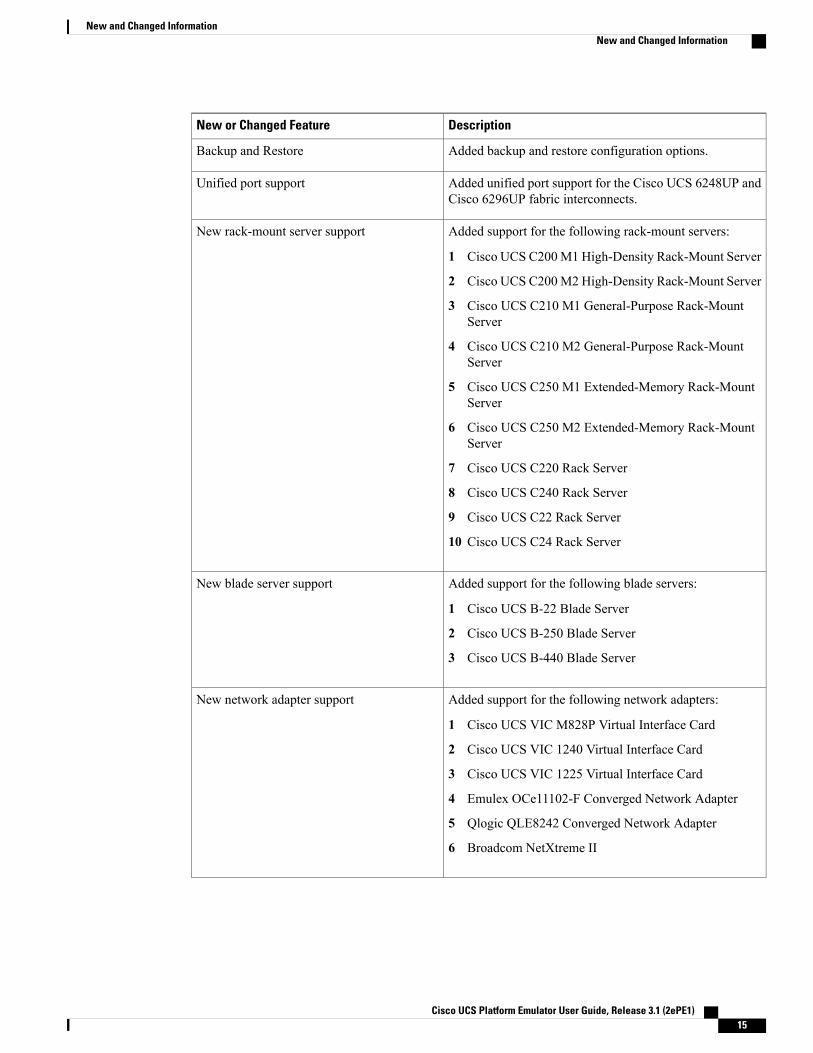
Added backup and restore configuration options.Backup and Restore
Added unified port support for the Cisco UCS 6248UP andCisco 6296UP fabric interconnects.
Unified port support
Added support for the following rack-mount servers:
1 Cisco UCS C200M1 High-Density Rack-Mount Server
2 Cisco UCS C200M2 High-Density Rack-Mount Server
3 Cisco UCS C210 M1 General-Purpose Rack-MountServer
4 Cisco UCS C210 M2 General-Purpose Rack-MountServer
5 Cisco UCS C250 M1 Extended-Memory Rack-MountServer
6 Cisco UCS C250 M2 Extended-Memory Rack-MountServer
7 Cisco UCS C220 Rack Server
8 Cisco UCS C240 Rack Server
9 Cisco UCS C22 Rack Server
10 Cisco UCS C24 Rack Server
New rack-mount server support
Added support for the following blade servers:
1 Cisco UCS B-22 Blade Server
2 Cisco UCS B-250 Blade Server
3 Cisco UCS B-440 Blade Server
New blade server support
Added support for the following network adapters:
1 Cisco UCS VIC M828P Virtual Interface Card
2 Cisco UCS VIC 1240 Virtual Interface Card
3 Cisco UCS VIC 1225 Virtual Interface Card
4 Emulex OCe11102-F Converged Network Adapter
5 Qlogic QLE8242 Converged Network Adapter
6 Broadcom NetXtreme II
New network adapter support
Cisco UCS Platform Emulator User Guide, Release 3.1 (2ePE1) 15
New and Changed InformationNew and Changed Information

DescriptionNew or Changed Feature
Added support for the Cisco Nexus 2232PP Fabric Extender.
Added an automatic rack server to fabric extenderconfiguration.
New Fabric Extender (FEX) support
Added information to use the vm console to change networksettings and to change the cluster status.
VM Console
Added requirement to use the Cisco UCS Platform EmulatorGUI only to change the persistent settings for the database(to reset or to preserve the database upon a restart).
Database Persistence Settings
Added information to launch UCSPE using VMplayer,VMfusion, VMware vSphere Hypervisor (ESXi) , andMicrosoft Hyper-V - on Windows or Linux.
Launching UCSPE
Updated requirements.System Requirements
Removed limitation about high availability mode.Known Issues
Table 12: New Features and Significant Behavioral Changes in Cisco UCS, Release 2.0(2s)
DescriptionNew or Changed Feature
Added an option to switch between standalone and clustermodes for the emulated fabric interconnects.
Enhanced fabric interconnect high availabilitysupport
Added support for the Cisco UCS B200 M3.New blade server
Added support for the Cisco UCS 6248 and 6296 fabricinterconnects.
New fabric interconnects
Added support for the Cisco UCS 2208XP I/O module.New I/O module
Added support for 1, 2, 4, or 8 uplinks from an I/O moduleto a fabric interconnect.
Enhanced connectivity between I/O modulesand fabric interconnects
Cisco UCS Platform Emulator User Guide, Release 3.1 (2ePE1)16
New and Changed InformationNew and Changed Information

C H A P T E R 2Overview
This chapter includes the following sections:
• Information About Cisco UCS Platform Emulator, page 17
• Cisco UCS Platform Emulator Control Panel, page 17
Information About Cisco UCS Platform EmulatorCisco UCS Platform Emulator is the Cisco UCS Manager application bundled into a virtual machine (VM).The VM includes software that emulates hardware communications for the Cisco Unified Computing System(Cisco UCS) hardware that is configured and managed by Cisco UCS Manager.
For example, you can use CiscoUCS PlatformEmulator to create and test a supported CiscoUCS configuration,or to duplicate an existing Cisco UCS environment for troubleshooting or development purposes.
For the latest hardware and software feature information, prerequisites, limitations, and caveats, see therelease notes for Cisco UCS Platform Emulator.
Note
Cisco UCS Platform Emulator Control Panel
Navigation PaneThe Navigation pane displays on the left side of the Cisco UCS Platform Emulator Control Panel. This paneenables you to navigate to all components in the Cisco UCS Platform Emulator.
INVENTORY Menu Tab
The items in this menu tab appear in the form of Equipment hierarchy and enable you to access and configuresettings for Chassis, Fabric Extenders, Rack Servers, and Fabric Interconnects in Cisco UCS PlatformEmulator.
Cisco UCS Platform Emulator User Guide, Release 3.1 (2ePE1) 17

Work PaneTheWork pane displays on the right side of Cisco UCS Platform Emulator Control Panel. TheWork paneincludes a content area that displays information related to the menu item selected in the Navigation pane.This comprises theMenu bar that contains the icons and theHardware Inventory Dashboard that containsthe list of chassis, rack servers, fabric extenders, fabric interconnects, blade servers and modular servers. Youcan view and modify information in theWork pane.
Hardware Inventory DashboardThe inventory of supported hardware components is stored and displayed in the Hardware Inventory dashboard.It contains the inventory of the supported components that you can use to build a chassis in Cisco UCS PlatformEmulator, including servers, fabric interconnects, and fabric extenders.
Hardware Inventory Menu and Dashboard Icons
The following table contains the icons above the Dashboard area and the icons used to perform functionssuch as editing and removing a device, duplicating a device and adding a new device.
DescriptionFunctionIcon
Adds a chassis, rack server or fabric extender.Add New Device
Duplicates the selected device.Duplicate
Opens the hardware inventory focus page where you can edit ormodify the device you selected.
Edit Device
Removes a device from the Emulator.Delete Device
Adds a template to create a chassis or a rack server.Add New Template
Cisco UCS Platform Emulator User Guide, Release 3.1 (2ePE1)18
OverviewWork Pane
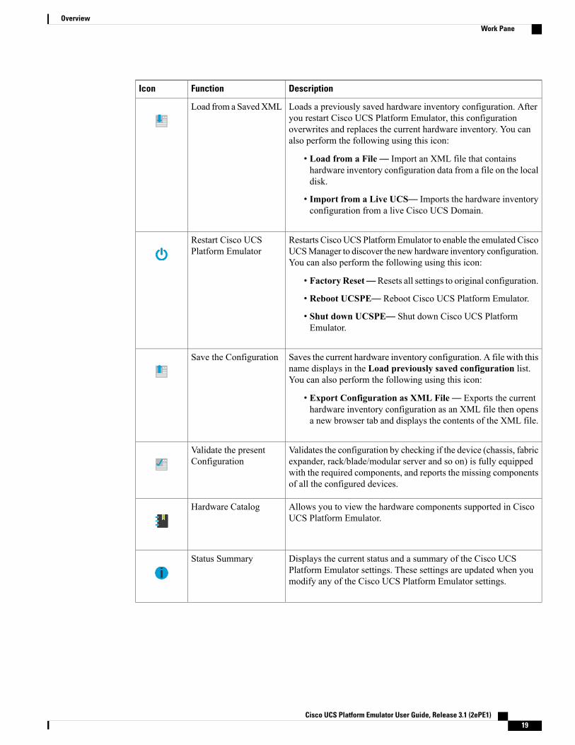
DescriptionFunctionIcon
Loads a previously saved hardware inventory configuration. Afteryou restart Cisco UCS Platform Emulator, this configurationoverwrites and replaces the current hardware inventory. You canalso perform the following using this icon:
• Load from a File— Import an XML file that containshardware inventory configuration data from a file on the localdisk.
• Import from a Live UCS— Imports the hardware inventoryconfiguration from a live Cisco UCS Domain.
Load from a SavedXML
Restarts Cisco UCS Platform Emulator to enable the emulated CiscoUCSManager to discover the new hardware inventory configuration.You can also perform the following using this icon:
• Factory Reset—Resets all settings to original configuration.
• Reboot UCSPE— Reboot Cisco UCS Platform Emulator.
• Shut down UCSPE— Shut down Cisco UCS PlatformEmulator.
Restart Cisco UCSPlatform Emulator
Saves the current hardware inventory configuration. A file with thisname displays in the Load previously saved configuration list.You can also perform the following using this icon:
• Export Configuration as XML File— Exports the currenthardware inventory configuration as an XML file then opensa new browser tab and displays the contents of the XML file.
Save the Configuration
Validates the configuration by checking if the device (chassis, fabricexpander, rack/blade/modular server and so on) is fully equippedwith the required components, and reports the missing componentsof all the configured devices.
Validate the presentConfiguration
Allows you to view the hardware components supported in CiscoUCS Platform Emulator.
Hardware Catalog
Displays the current status and a summary of the Cisco UCSPlatform Emulator settings. These settings are updated when youmodify any of the Cisco UCS Platform Emulator settings.
Status Summary
Cisco UCS Platform Emulator User Guide, Release 3.1 (2ePE1) 19
OverviewWork Pane
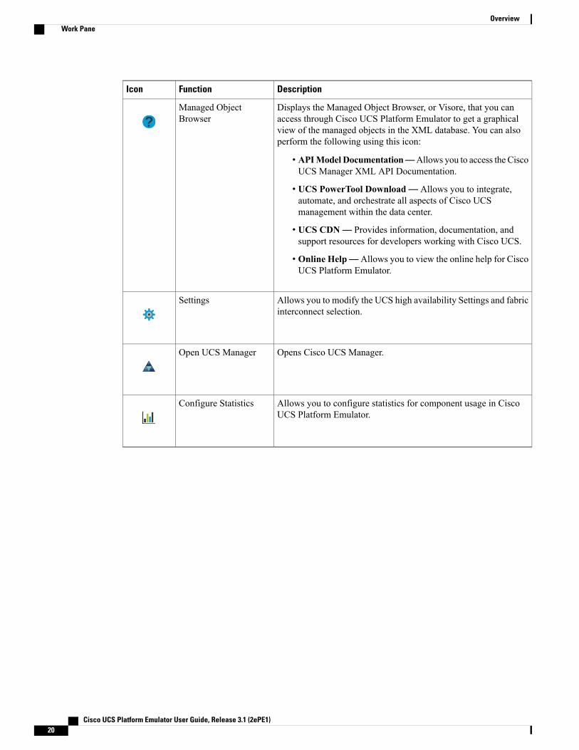
DescriptionFunctionIcon
Displays the Managed Object Browser, or Visore, that you canaccess through Cisco UCS Platform Emulator to get a graphicalview of the managed objects in the XML database. You can alsoperform the following using this icon:
• APIModel Documentation—Allows you to access the CiscoUCS Manager XML API Documentation.
• UCS PowerTool Download— Allows you to integrate,automate, and orchestrate all aspects of Cisco UCSmanagement within the data center.
• UCS CDN— Provides information, documentation, andsupport resources for developers working with Cisco UCS.
• Online Help— Allows you to view the online help for CiscoUCS Platform Emulator.
Managed ObjectBrowser
Allows you to modify the UCS high availability Settings and fabricinterconnect selection.
Settings
Opens Cisco UCS Manager.Open UCS Manager
Allows you to configure statistics for component usage in CiscoUCS Platform Emulator.
Configure Statistics
Cisco UCS Platform Emulator User Guide, Release 3.1 (2ePE1)20
OverviewWork Pane

C H A P T E R 3Installing and Running Cisco UCS PlatformEmulator Using the VM Console
This chapter includes the following sections:
• IP Address for Cisco UCS Platform Emulator, page 21
• Installing and Launching Cisco UCS Platform Emulator, page 22
• Launching Cisco UCS Platform Emulator Using Hypervisors, page 22
• Viewing System Settings Using VM Console, page 25
• Modifying System Settings Using VM Console, page 26
• Modifying Network Settings Using the VM Console, page 26
• Restarting and Rebooting Cisco UCS Platform Emulator Using the VM Console, page 27
• Starting the Cisco UCS Manager CLI Using the VM Console, page 28
IP Address for Cisco UCS Platform EmulatorCisco UCS Platform Emulator supports both DHCP and static IP. By default, Cisco UCS Platform Emulatoris configured to use the local network to obtain an IP address via DHCP. If your network does not include aDHCP server, you must assign a static IP address to Cisco UCS Platform Emulator.
After the initial installation completes, Cisco UCS Platform Emulator displays the management IP address inthe VM console. If you assign a static IP address, the IP address persists across VM reboots. If the IP addresswas assigned by DHCP server, the IP address persists across VM reboots for the duration of the lease.
When connecting to the UCS Platform Emulator VM Console through the SSH, we recommend that youkeep open a single session.
Note
Cisco UCS Platform Emulator User Guide, Release 3.1 (2ePE1) 21

Installing and Launching Cisco UCS Platform Emulator
The VM performs a one-time installation process the first time it starts up. Allow the installation tocomplete before you reboot the VM.
Note
Procedure
Step 1 Extract the Cisco UCS Platform Emulator .zip file and .ova file to a folder.Step 2 Open or import the unzipped Cisco UCS Platform Emulator into a supported hypervisor, as required by the
hypervisor.Do not continue with the next step until the VM has finished booting.
Step 3 (Optional) If you have a DHCP server setup, the Cisco UCS Platform Emulator requests for the IP addressesfrom the DHCP server during startup (three IP addresses are requested) and the IP assigned is displayed onthe login screen. Enter this IP address in a supported Mozilla-based web-browser to open the home screen ofCisco UCS Platform Emulator.
Step 4 (Optional) If you want to assign a static IP address to Cisco UCS Platform Emulator, do the following (youare required to enter three IP addresses as described in step e):a) In the VM console window, at the ucspe login prompt, enter ucspe and press Enter.b) At the Password prompt, enter ucspe and press Enter.c) At the Select prompt, enter n to change the network settings. A brief overview of current network settings
is displayed.d) At theModify Connections prompt, enter y to modify connections.e) At the Set Network Mode prompt, enter c to configure custom network.
Repeat the following steps f. and g. three times, one for each interface.
f) At the Enter <Interface> IP prompt, enter the static IP address to configure and press Enter.g) At the Enter <Interface> Netmask prompt, enter the Netmask to configure and press Enter.h) At the Enter Gateway IP prompt, enter the IP address of the default gateway press Enter.After you enter the default gateway, the network interface reinitializes with your settings and the systembecomes accessible through the new IP address. To cancel an entry and return to the menu, press Ctrl+C.
Launching Cisco UCS Platform Emulator Using HypervisorsYou can launch Cisco UCS Platform Emulator using VMplayer, VMfusion, VMware vSphere Hypervisor(ESXi), and Microsoft Hyper-V.
Launching Cisco UCS Platform Emulator Using Hypervisors With An .ova File
Using VMplayer on Microsoft Windows and Linux, Release 5.0:
Cisco UCS Platform Emulator User Guide, Release 3.1 (2ePE1)22
Installing and Running Cisco UCS Platform Emulator Using the VM ConsoleInstalling and Launching Cisco UCS Platform Emulator

1 Download the VMware OVF Tool, Release 3.0.1 from VMware. You can download the tool from thewebsite.
2 When the download is complete, open your terminal or command prompt, navigate to where the VMwareOVF Tool was installed and run the following to convert the image to a VMX file:ovftool <path_to_ova\UCSPE.ova> <path_to_store_converted_image\UCSPE.vmx>
The conversion begins and a progress window is displayed. When finished, you can use VMware playerto open the converted image and launch Cisco UCS Platform Emulator.
3 From the File menu on the VMware Player menu bar, select Open a Virtual Machine.
4 Browse to the folder where the VMX file was converted and double-click the VMX file to launch CiscoUCS Platform Emulator.
Launching Cisco UCS Platform Emulator Using Hypervisors With a .zip File
The .zip file contains the VMX and VMDK files that can be used directly with VMware Player, VMwareWorkstation and VMware Fusion.
1 Download the .zip file.
2 Extract the .zip file to a folder.
3 Click Open a Virtual Machine and browse to the extracted files. Select the VMX file and click Open..
4 To install in vSphere, the VMDK files must be processed with VMware Converter Standalone, thendeployed to vCenter directly.
5 Open VMware Converter Standalone.
6 In the Converter view pane, select Convert Machine
7 Set the source type as VMware Workstation or Other Virtual Machine.
8 Select the VMX file from the folder. Click Next.
9 Enter the destination information for the vCenter Server.
10 Select a destination cluster resource, and suitable datastore.
11 Click on Finish
12 When the conversion completes successfuly, power on the VM.
Launching Cisco UCS Platform Emulator Using Microsoft Hyper-V With a .zip File
This task applies to the .zip file only; for example,Cisco_UCS_Platform_Emulator_3.1(2bPE1).zip. CiscoUCSPlatformEmulator is deliveredas an .ova file and as a .zip file. Each file contains the VMX and VMDK files that can be used directlywith VMware Player, VMware Workstation and VMware Fusion.
Note
1 Download the .zip file.
2 Extract the .zip file to a folder.
Cisco UCS Platform Emulator User Guide, Release 3.1 (2ePE1) 23
Installing and Running Cisco UCS Platform Emulator Using the VM ConsoleLaunching Cisco UCS Platform Emulator Using Hypervisors

3 Download the StarWindV2V converter fromwww.starwindsoftware.com. Install the converter inMicrosoftWindows.
4 Launch the StarWind converter and convert the UCSPE.vmdk file into VHD or VHDX format. Use theMicrosoft Virtual PC growable image or VHDX as the destination image format.
5 Once you have a .vhd or .vhdx image for the platform emulator you would like to use, you can create anew VM. On Windows 2012 R2, if you are using the Hypervisor Manager to create a VM, you can selectNew > Virtual Machine from the Actions pane to launch the VMWizard and configure the VM with thefollowing settings:
1 Specify a name of your choice for the VM. Optionally, specify a different location to store your VM.
2 Specify Generation 1.
3 Set the startup memory to 1024 MB. Disable the use of dynamic memory..
4 Choose an available Virtual Switch.
Hypervisor switch settings should be configured before you configure the VM. There are options forexternal, internal, and private switch configurations. If you wish to use internally configured IPs and NAT,we recommend you refer to the Hyper-VNATConfiguration Document for more information. Additionally,note that NAT is an available option on Windows build 14295 and later (Windows/Hyper-V Server 2012and Windows 10).
Note
5 UnderConnect Virtual Hard Disk, selectUse an existing virtual hard disk and browse to your .vhdor .vhdx file.
6 Once you have completed creating a VM, select Settings for the new VM, and select Add Hardware> Network Adapter, and click Add.
7 For the new Network Adapter, select the same virtual switch you used in step number 4 and clickOK.
8 Repeat steps 6 and 7, and add a third network adapter. Verify that the VM is reporting three networkadapters on the desired Virtual Switch from the Networking summary tab, or by selecting Settingsagain.
9 Select Start to start the VM after verifying the settings, and then selectConnect to connect to the VMconsole.
10 Once the Cisco UCS Platform Emulator boot is complete, you can verify and/or modify IP settings.Cisco UCS Platform Emulator supports both DHCP and static IP, and by default, is configured to usethe local network to obtain an IP address through the DHCP. If your network does not include a DHCPserver, you must assign a static IP address. To see the version number of Cisco UCS Platform Emulatoryou are using, see the User Guide.
11 Once you configure the networking successfully, you can connect to the IP shown in the Cisco UCSPlatform Emulator VM console.
Launching Cisco UCS Platform Emulator Using VMware Fusion on Mac OS X With an .ova File
If you are running VMware Fusion 4 or below, you can use the VMware OVF Tool to convert the image tothe VMware runtime file format (.vmx). VMware Fusion 5 can import the .ova image file without conversion.
Cisco UCS Platform Emulator User Guide, Release 3.1 (2ePE1)24
Installing and Running Cisco UCS Platform Emulator Using the VM ConsoleLaunching Cisco UCS Platform Emulator Using Hypervisors

1 From the File menu on the VMware Fusion menu bar, select Import. The Import Library window displaysa dialog box for browsing to the location of the .ovf file.
2 Browse to the .ova file and click Open.
3 Type the name for the imported virtual machine in the Save As text box and indicate where to save it. Thedefault destination is the Virtual Machines folder created by VMware Fusion.
4 Click Import. A status bar indicates the progress of the import process.
When the import is complete, the virtual machine appears in the virtual machine library and in a separatevirtual machine window.
Launching Cisco UCS Platform Emulator Using VMware Workstation on Microsoft Windows and Linux Withan .ova File
You can directly import an .ova file into VMware Workstation 8.
1 From the File menu on the VMware Workstation 8 menu bar, select Open.
2 Browse to the .ovf or .ova file and click Open.
3 Type a name for the virtual machine, browse to the directory for the virtual machine files, and click Import.
Launching Cisco UCS Platform Emulator Using VMware vSphere ESXi 5.0 With an .ova File
Connect to your VMware Vcenter or VMware vSphere ESXi using the vSphere client.
1 From the File menu in the Vcenter or ESXi menu bar, select Deploy OVF Template.
2 Browse to the .ova file and click Open.
Viewing System Settings Using VM ConsoleYou can use the Cisco UCS Platform Emulator VM console to view system status and configurations.
Procedure
Step 1 At the ucspe login, enter the username ucspe and press Enter.Step 2 At the Password prompt, enter ucspe and press Enter.
The VM console displays the Options menu.
Step 3 At the Select prompt, enter a to show the status and press Enter.Multiple system statuses and configurations are displayed:
• The current version of Cisco UCS Platform Emulator is displayed on top.
• The current Network Mode and the Network Interface Configurations are displayed.
Cisco UCS Platform Emulator User Guide, Release 3.1 (2ePE1) 25
Installing and Running Cisco UCS Platform Emulator Using the VM ConsoleViewing System Settings Using VM Console

Modifying System Settings Using VM ConsoleYou can use the Cisco UCS Platform Emulator VM console to change some of the UCS Platform Emulatorconfigurations.
Procedure
Step 1 At the ucspe login, enter the username ucspe and press Enter.Step 2 At the Password prompt, enter ucspe and press Enter.
The VM console displays the Options menu.
Step 3 At the Select prompt, enter t to modify system settings.Step 4 At theModify System Settings, select one of the following options:
a) Enter h to modify High-Availability Mode and press Enter. The current status of the High AvailabilityMode is displayed (Stand Alone or Clustered).- At the Set High Availability prompt, enter s to change to Stand Alone or c to change to Clustered, andpress Enter. After modification, the Cisco UCS Platform Emulator and Cisco UCS Manager restart.
b) Enter t to modify system date/time and press Enter. The current date and time is displayed.At the Change Date prompt, press y to change the date. If you choose not to change the date and skip toChange Time instead, press n. Enter the new date in dd/mm/yyyy format and press Enter.
At the Change Time prompt, press y to change the time. If you choose not to change time and exit to themain menu, press n. Enter the new time in hh:mm:ss format and press Enter.
c) Enter n to modify the Network Time Protocol (NTP) server settings.At the prompt, enter the IP address of a valid Time Server running NTP. Cisco UCS Platform Emulatorconnects to the Time server and synchronizes its system time with the server.
If you entered invalid data in the settings, the modification process aborts and the system reverts tothe original menu options.
Note
Modifying Network Settings Using the VM ConsoleYou can use the Cisco UCS Platform Emulator VM console to change some network settings of the VM.
Procedure
Step 1 At the ucspe login, enter the username ucspe and press Enter.Step 2 At the Password prompt, enter ucspe and press Enter.
The VM console displays the Options menu.
Step 3 At the Options Select prompt, enter n to modify network settings.A brief summary of current network settings with the IP address, netmask and hardware address of theinterfaces, is displayed.
Cisco UCS Platform Emulator User Guide, Release 3.1 (2ePE1)26
Installing and Running Cisco UCS Platform Emulator Using the VM ConsoleModifying System Settings Using VM Console

Step 4 At theModify Connections prompt, enter y and press Enter.Step 5 At the Set NetworkMode prompt, choose the network mode by entering a for AutoMode; d for DHCPMode
and c for Custom Mode.
• Auto Mode—This is the default mode of the Cisco UCS Platform Emulator. In this mode, the CiscoUCS Platform Emulator checks for DHCP servers first as shown below.
• DHCP Mode—In this mode, the Cisco UCS Platform Emulator searches only for an available DHCPServer. Upon obtaining IP addresses for all the interfaces, the Cisco UCS Platform Emulator and CiscoUCS Manager restart automatically.
• Custom Mode— In this mode, the Cisco UCS Platform Emulator skips checking for available DHCPservers and directly uses the custom configuration that the user provides. Complete steps a and b onceif Cluster Mode is Stand Alone, and thrice if Cluster Mode is Clustered.
a) At the Enter eth[0,1,2] IP prompt, enter the static IP address for the interface.b) At the Enter eth[0,1,2] Netmask prompt, enter the netmask for the interface.c) At the Enter Gateway IP prompt, enter the default gateway IP address.The Cisco UCS Platform Emulator and Cisco UCS Manager restarts and come up with the configured IPaddress.
Restarting and Rebooting Cisco UCS Platform Emulator Usingthe VM Console
You can use the Cisco UCS Platform Emulator VM console to restart and reboot UCSPE.
Procedure
Step 1 At the cisco-ucspe login prompt, type username ucspe and press Enter.Step 2 At the Password prompt, type ucspe and press Enter.
The VM console window displays the Options menu.
a) Press s to restart Cisco UCS Platform Emulator processes and press Enter. At the Confirm prompt, entery and press Enter. This restarts all the Cisco UCS Platform Emulator processes including the Cisco UCSManager process. The Cisco UCS Manager Database resets based on the configuration. (To change this,see the Modifying System Settings Using VM Console, on page 26 section).
You should perform Cisco UCSManager backup operations to preserve the Cisco UCSManagerconfiguration through all the VM reboots.
Note
b) Press f to perform a Factory Reset and press Enter. At theConfirm prompt, enter y and press Enter. Thisresets all configurations and settings to the original settings of the Cisco UCS Platform Emulator.
c) Press r to reboot the VM and press Enter. At the Confirm prompt, enter y and press Enter. This restartsthe VM.
d) Press x to logout user and press Enter. At the Confirm prompt, enter y and press Enter. This logs outthe current Cisco UCS Platform Emulator user and takes you back to the login screen.
Cisco UCS Platform Emulator User Guide, Release 3.1 (2ePE1) 27
Installing and Running Cisco UCS Platform Emulator Using the VM ConsoleRestarting and Rebooting Cisco UCS Platform Emulator Using the VM Console

e) Press z to shutdown the VM and press Enter. At theConfirm prompt, enter y and press Enter. This shutsdown the VM.
Starting the Cisco UCS Manager CLI Using the VM ConsoleYou can use the supported commands from the Cisco UCSManager CLI to configure andmanage the hardwarein your Cisco UCS Platform Emulator environment. The console window for the Cisco UCS Platform EmulatorVM supports a single CLI session.
For information about Cisco UCS Manager CLI commands, see the Cisco UCS Manager CLI ConfigurationGuide and the Cisco UCS Manager CLI Command Reference. You can access these documents through theCisco UCS B-Series Servers Documentation Roadmap available at the following URL: http://www.cisco.com/go/unifiedcomputing/b-series-doc .
Cisco UCS Platform Emulator does not support Cisco UCS Manager CLI commands for unsupportedfeatures or within the connect nxos or connect local-mgmt scopes
Note
Procedure
Step 1 At the ucspe login prompt, type username ucspe and press Enter.Step 2 At the Password prompt, type ucspe and press Enter.
The VM console displays the Options menu.
Step 3 Press c to log on to the CLI console and press EnterThe VM Console window now displays the ucspe# prompt, which is the equivalent of the top-level scope inthe Cisco UCS Manager CLI.
Cisco UCS Platform Emulator User Guide, Release 3.1 (2ePE1)28
Installing and Running Cisco UCS Platform Emulator Using the VM ConsoleStarting the Cisco UCS Manager CLI Using the VM Console

C H A P T E R 4Restarting and Shutting Down Cisco UCSPlatform Emulator Using the Control Panel
This chapter includes the following sections:
• Restarting Cisco UCS Platform Emulator, page 29
• Restarting Cisco UCS Platform Emulator and Performing a Factory Reset, page 29
• Rebooting the Cisco UCS Platform Emulator VM, page 30
• Shutting Down the Cisco UCS Platform Emulator VM, page 30
Restarting Cisco UCS Platform EmulatorProcedure
Step 1 In theWork pane, click the Power icon on the menu bar.Step 2 Select Restart UCSPE.Step 3 For the question Are you sure you want to restart UCS Emulator with Current Settings now?, select Yes
and click the Restart Cisco UCS Platform Emulator with current settings button to restart Cisco UCSEmulator, or select No and click the Restart Cisco UCS Platform Emulator with current settings buttonto cancel the restart.
Restarting Cisco UCS Platform Emulator and Performing aFactory Reset
By default, when Cisco UCS Platform Emulator restarts, the database is erased, any hardware that you addedto Cisco UCS Manager within Cisco UCS Platform Emulator is deleted, and all configurations and settingsare returned to the factory defaults.
Cisco UCS Platform Emulator User Guide, Release 3.1 (2ePE1) 29
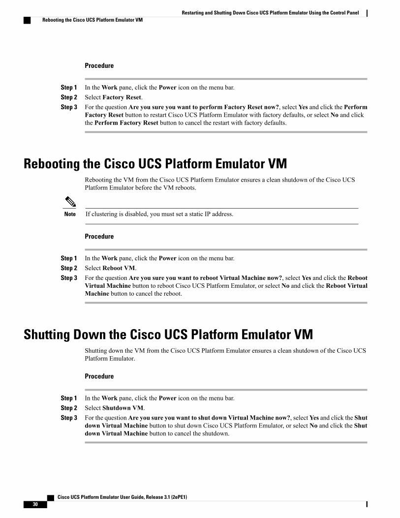
Procedure
Step 1 In theWork pane, click the Power icon on the menu bar.Step 2 Select Factory Reset.Step 3 For the question Are you sure you want to perform Factory Reset now?, select Yes and click the Perform
Factory Reset button to restart Cisco UCS Platform Emulator with factory defaults, or select No and clickthe Perform Factory Reset button to cancel the restart with factory defaults.
Rebooting the Cisco UCS Platform Emulator VMRebooting the VM from the Cisco UCS Platform Emulator ensures a clean shutdown of the Cisco UCSPlatform Emulator before the VM reboots.
If clustering is disabled, you must set a static IP address.Note
Procedure
Step 1 In theWork pane, click the Power icon on the menu bar.Step 2 Select Reboot VM.Step 3 For the question Are you sure you want to reboot Virtual Machine now?, select Yes and click the Reboot
Virtual Machine button to reboot Cisco UCS Platform Emulator, or select No and click the Reboot VirtualMachine button to cancel the reboot.
Shutting Down the Cisco UCS Platform Emulator VMShutting down the VM from the Cisco UCS Platform Emulator ensures a clean shutdown of the Cisco UCSPlatform Emulator.
Procedure
Step 1 In theWork pane, click the Power icon on the menu bar.Step 2 Select Shutdown VM.Step 3 For the questionAre you sure you want to shut down Virtual Machine now?, selectYes and click the Shut
down Virtual Machine button to shut down Cisco UCS Platform Emulator, or select No and click the Shutdown Virtual Machine button to cancel the shutdown.
Cisco UCS Platform Emulator User Guide, Release 3.1 (2ePE1)30
Restarting and Shutting Down Cisco UCS Platform Emulator Using the Control PanelRebooting the Cisco UCS Platform Emulator VM

C H A P T E R 5Configuring Cisco UCS Platform Emulator
This chapter includes the following sections:
• Viewing the Cisco UCS Platform Emulator Current Status and Settings, page 31
• Modifying the Cisco UCS Manager High Availability Setting, page 33
• Configuring Statistics in Cisco UCS Platform Emulator, page 34
• Modifying the Fabric Interconnect Emulation Settings, page 34
• Configuring Cisco UCS Platform Emulator Restart Settings, page 35
Viewing the Cisco UCS Platform Emulator Current Status andSettings
Procedure
Step 1 In the Work pane, click the Status Summary icon from the menu bar.Step 2 View the current status and settings of in the Status Summary page.
Status Summary PageThe Status Summary page displays the current status and a summary of the Cisco UCS Platform Emulatorsettings. These settings are updated when you modify any of the Cisco UCS Platform Emulator settings.
Runtime Status Area
This area provides information about the current status of Cisco UCS Platform Emulator. The number inparentheses shows the number of instances of the processes that are running. This example is for a clustersetting. For a non-cluster (standalone setting), everything will be (1) and the SAM Controller will not berunning.
Cisco UCS Platform Emulator User Guide, Release 3.1 (2ePE1) 31

DescriptionName
Running(1)Emulator field
Running(2)UCS Manager field
Running(2)Blade AG field
Running(2)RsdAG field
Running(2)PortAG field
Running(2)StatsAG field
Running(2)NicAG field
Running(2)DcosAG field
Running(2)HostagentAG field
Running(2)ExtvmmAG field
Running(2)SAM Controller field
The memory currently available to Cisco UCS Platform Emulator.Available Memory field
The current management IP address.Current Mgmt IP field
The netmask configured for Cisco UCS Platform Emulator.Netmask field
The gateway configured for Cisco UCS Platform Emulator.Gateway field
Management IP Settings Area
This area provides details of the management IP address configured for Cisco UCS Platform Emulator.
DescriptionName
Customized network mode.Network Mode field
IP address of the host.IP Address field
Specifies the network's subnet.Netmask field
Node that forwards packets to other networks.Default Gateway field
Emulator Startup Settings Area
This area provides details of the fabric interconnect configuration for Cisco UCS Platform Emulator.
Cisco UCS Platform Emulator User Guide, Release 3.1 (2ePE1)32
Configuring Cisco UCS Platform EmulatorStatus Summary Page

DescriptionName
The number of fabric interconnects configured for Cisco UCS PlatformEmulator. This can be one of the following:
• On
• Off
High-Availability Mode field
Emulator Hardware Config Area
DescriptionName
The location where the startup configuration for Cisco UCS PlatformEmulator is stored.
Startup Config URL field
NTP Settings Area
DescriptionName
Synchronizes time stamps of the system. This could be one of thefollowing:
• Synchronized
• Unsynchronized
NTP Server field
Current time and date.System Date/Time field
Record of the last NTP updates.Last NTP Update Log field
Modifying the Cisco UCS Manager High Availability SettingThe High Availability setting determines which of the following configurations is emulated by Cisco UCSPlatform Emulator:
• High availability cluster configuration with two fabric interconnects
• Single standalone fabric interconnect
Cisco UCS Platform Emulator User Guide, Release 3.1 (2ePE1) 33
Configuring Cisco UCS Platform EmulatorModifying the Cisco UCS Manager High Availability Setting

Procedure
Step 1 In theWork pane, click the Settings icon.Step 2 Select Change Cluster State.Step 3 On theModify UCS High Availability Settings and FI selection page, click one of the following radio
buttons:
• Dual Fabric Interconnect, HA
• Single Fabric Interconnect, no HA
Step 4 Click Submit.This forcefully restarts Cisco UCS Platform Emulator for changes to take effect. Changing the mode resetsall the connections.
Configuring Statistics in Cisco UCS Platform EmulatorProcedure
Step 1 In theWork pane, click the Statistics icon from the menu bar.Step 2 From the device hierarchy, select the desired device.
Configured statistics policies are displayed.
Step 3 To edit the policy of a specific statistic, click the Edit icon and select one of the policies:
• Fixed— allows you to set a fixed value.
• Random— allows you to set a random value.
• Increment— allows you to set an incrementing factor.
Step 4 Enter a value in the text box for the selected policy and click OK.This changes the configuration for the statistics of that device.
Step 5 Click the Reset to Default button to reset the configuration.
Modifying the Fabric Interconnect Emulation SettingsThis setting determines which fabric interconnect is used by Cisco UCS Platform Emulator.
Cisco UCS Platform Emulator User Guide, Release 3.1 (2ePE1)34
Configuring Cisco UCS Platform EmulatorConfiguring Statistics in Cisco UCS Platform Emulator

Procedure
Step 1 In theWork pane, click the Settings icon.Step 2 Select Fabric Interconnect.Step 3 On theModify UCS Fabric Interconnect Emulation Settings page, select the desired fabric interconnect
model from the Fabric Interconnect drop-down list.Step 4 Click Submit.
This restarts the Cisco UCS Platform Emulator for changes to take effect.
Configuring Cisco UCS Platform Emulator Restart SettingsThe Cisco UCS Platform Emulator Restart Settings allow you to configure settings for actions that are requiredwhenever the Platform Emulator restarts.
Modifying Insert Device Settings
You can use this setting when all devices need to be inserted once the Cisco UCS Platform Emulator restarts.If the links of any device are not connected, they are automatically connected and then inserted into the CiscoUCS Manager.
Procedure
Step 1 In theWork pane, click the Settings icon from the menu bar.Step 2 Select UCSPE Restart Settings.Step 3 Click the Yes radio button to insert all devices after a restart, or the No radio button to cancel the action.Step 4 Click Submit.
Cisco UCS Platform Emulator User Guide, Release 3.1 (2ePE1) 35
Configuring Cisco UCS Platform EmulatorConfiguring Cisco UCS Platform Emulator Restart Settings

Cisco UCS Platform Emulator User Guide, Release 3.1 (2ePE1)36
Configuring Cisco UCS Platform EmulatorConfiguring Cisco UCS Platform Emulator Restart Settings

C H A P T E R 6Configuring the Hardware Inventory
This chapter includes the following sections:
• Viewing the Hardware Catalog, page 37
• Manually Configuring the Hardware Inventory, page 38
• Using Existing Hardware Inventory Configurations, page 47
Viewing the Hardware CatalogProcedure
Step 1 On the Hardware Inventory Dashboard page, click the Hardware Catalog icon.Step 2 In theWork pane, click one or more of the following tabs to view the components supported in the current
release:
• Fabric Interconnect
• Chassis
• DIMM
• IOM
• FEX
• Blade Servers
• Rack Servers
•Modular Servers
• CPU
• DIMM
• Disks
• Adaptors
Cisco UCS Platform Emulator User Guide, Release 3.1 (2ePE1) 37

• Fans
• PSU
• Storage Controllers
Manually Configuring the Hardware InventoryYou can manually configure the hardware inventory in theWork pane using the options listed for hardwarecomponents on the Hardware Inventory Dashboard.
Adding a New Chassis
Procedure
Step 1 On the Hardware Inventory Dashboard, click the Add Device icon next to the Chassis heading.Step 2 In the Name field, enter a name for the chassis.Step 3 In the Pid field, select a server from the drop down list.Step 4 Click Add.
Cisco UCS Platform Emulator adds aChassis and the following message is displayed below theMenu icons:Successfully created chassis with serial :: <Chassis serial>
Fabric Model UCS-FI-M-6324 is only supported with the chassis UCSB-5108-AC2 andUCSB-5108-DC2. However, you can connect a secondary chassis N20-C6508 to the UCS Minichassis. To know how tomanage links between devices, seeManaging Connectivity of Links BetweenDevices, on page 45.
Note
Creating a New Rack Server
Procedure
Step 1 On the Hardware Inventory Dashboard, click the Add Device icon next to the Rack Server heading.Step 2 In the Name field, enter a name for the rack server.Step 3 In the Pid field, select the type of server from the drop down list.Step 4 Click Add.
Cisco UCS Platform Emulator adds a Rack Server and the following message is displayed below theMenuicons:Successfully created rack server :: <rack server name>, with serial :: <serial number>..
Cisco UCS Platform Emulator User Guide, Release 3.1 (2ePE1)38
Configuring the Hardware InventoryManually Configuring the Hardware Inventory

What to Do Next
Add a new template to the rack server you just created or an existing rack server. Click theAddNewTemplateicon next to the Rack Server heading, select the rack server from a drop down list and click Add.
When you add a rack server, on the rack server's focus page, you can select the mode with which the rackserver connects, that is, it can directly connect to a fabric interconnect (DAS mode) or through a fabricextender (SWM and DWM modes). To know how to manage links between devices, see ManagingConnectivity of Links Between Devices, on page 45.
Note
Creating a New Fabric Extender
Procedure
Step 1 On the Hardware Inventory Dashboard, click the Add Device icon next to the Fabric Extender heading.Step 2 In the Name field, enter a name for the fabric extender.Step 3 In the Side field, select side A or B from a drop down list.Step 4 In the Pid field, select the fabric extender model from the drop down list.Step 5 Click Add.
Cisco UCS Platform Emulator adds a Fabric Extender and the following message is displayed below theMenu icons:Successfully created Fex :: <fabric extender name>, with serial ::<serial number>.
To know how to manage links between devices, see Managing Connectivity of Links Between Devices, onpage 45.
Creating a New Blade ServerYou can create a new blade server in theChassis area of the Chassis Focus page. However, a new blade serverdoes not contain any components, such as DIMMs, adapters, or fans. Once you create a new blade server,you may edit the device from the Dashboard area to add the individual components.
Cisco UCS Platform Emulator User Guide, Release 3.1 (2ePE1) 39
Configuring the Hardware InventoryCreating a New Fabric Extender

Procedure
Step 1 On the Hardware Inventory Dashboard, click the Edit Device icon for a chassis you select from the Chassislist area.
Step 2 In the hardware catalog table in the Chassis Focus page, click on the blade server and, holding the mousebutton down, drag and drop it to the Chassis area.
Step 3 In the Enter Server Slot field, enter the number of the empty slot where you want to insert the blade serverand press Enter.
Step 4 (Optional) Click the Validate icon on the Dashboard to ensure that all necessary components for a server areadded. Missing components are displayed if the component is missing on the server.
Step 5 Complete the following steps to add the components to the blade server:a) Click the Edit Device icon in the Blade Server area of the dashboard.b) From the hardware catalog table on the Blade Server Focus page, click the desired component and, holding
the mouse button down, drag the component to the Server Slot area.c) Enter the desired slot number for the component when prompted, and press Enter.d) Repeat Steps a through c until you have added all desired components to the blade server.
For the UCS C3260 system, the following configurations are additionally supported:Note
• Server in slot 1 and HDD Expansion Tray in slot 2.
• Server (UCSC-C3K-M4SRB) in slot 2 and IO Expander in slot 1.
To know more about creating an HDD Expansion Tray and IO Expander, see Creating aHard Disk Drive Expansion Tray, on page 40 and Creating an IO Expander, on page 41.
Creating a Hard Disk Drive Expansion TrayYou can add a Hard Disk Drive (HDD) expansion tray from the chassis area.
Procedure
Step 1 On theHardware InventoryDashboard, click the Edit Device icon for a chassis you select from the Chassislist area.
Step 2 In the hardware catalog table in the Chassis Focus page, click the disk and, holding the mouse button down,drag and drop it to the Chassis area.
Step 3 In the Enter Disk Slot field, enter a slot in the range of 57-60.Step 4 Press Enter.
Disks with the above range on a C3260 system represent the HDD expansion tray.The HDD expansion tray gets added to slot number 2 on the C2360 Chassis if the slot is not alreadyoccupied by a server.
Note
Cisco UCS Platform Emulator User Guide, Release 3.1 (2ePE1)40
Configuring the Hardware InventoryCreating a Hard Disk Drive Expansion Tray

Creating an IO ExpanderYou can create an IO expander in the Server area.
Procedure
Step 1 On the Hardware Inventory Dashboard, click the Edit Device icon for the UCSC-C3K-M4SRB server inslot 2.
Step 2 In the hardware catalog table in the Server Focus page, click the disk or controller tab and, holding the mousebutton down, drag and drop either component to the Server area.
Step 3 In the Enter Slot field, enter a slot in the range 4-6 to add controllers, or enter a slot in the range 4-5 to adddisks.
Step 4 Press Enter.Disks and controllers in the above ranges represent an IO Expander.
An IO Expander is created only if slot number 1 is empty, with UCSC-C3K-M4SRB in slot 2. Itoccupies slot 1 of the chassis. Controller slot number 3 is used to connect the IO Expander with theserver. Therefore, in order to create an IO Expander, delete any controller in slot number 3.
Note
Modifying Hardware ComponentsAfter you create a chassis, server, or fabric extender, you can modify these components from their individualareas in a dedicated Focus page that also includes aConnectivity area and the respectiveHardware Catalogtable located below.
You can arrive at the Focus page by clicking the Edit Device icon of the individual hardware componentfrom the hardware list on the Hardware Inventory Dashboard area.
Modifying Chassis Components
Procedure
Step 1 Click the Edit Device icon in the Chassis area of the Hardware Inventory Dashboard.The Chassis Focus page is displayed.
Step 2 From the Hardware Catalog table on the Focus page, click the row for the desired component, drag thecomponent to the Chassis area, and drop it.
Step 3 When prompted, enter the desired slot number and press Enter.Step 4 Repeat Steps 3 and 4 until you have added all the desired components.
On a chassis with PID UCSC-C3X60-BASE, an additional HDD Expansion Tray and IO Expanderare supported in a server slot. You may also add PSU and FANs. However, for other chassis PIDs,only PSU and FANs are permitted to be dropped on the chassis.
Note
Cisco UCS Platform Emulator User Guide, Release 3.1 (2ePE1) 41
Configuring the Hardware InventoryCreating an IO Expander

Modifying Rack and Blade Server Components
Procedure
Step 1 Click the Edit Device icon in the Server area of the Hardware Inventory dashboard.Step 2 From the hardware catalog table on the Focus page, click the row for the desired component, drag the
component to the Server area and drop it.Step 3 When prompted, enter the desired slot number or a slot number range, and press Enter.Step 4 Repeat Steps 2 and 3 until you have added all desired components.
Duplicating a DeviceYou can duplicate a server, fex, or chassis from the Hardware Inventory Dashboard or from the individualcomponent area on the Focus page.
Procedure
On the Hardware Inventory Dashboard, click the Duplicate Device icon in the fex, server, or chassis listareas (tables).Cisco UCS Platform Emulator duplicates the device and the following message is displayed below theMenuicons:Successfully duplicated <device> ::<serial number> to new <device> ::<serial number>
When you duplicate a device, Cisco UCS Platform Emulator duplicates all the components under it(blades, DIMMs, disks, controllers and so on) and also assigns each component a unique serialnumber.
Note
Inserting a Device into Cisco UCS ManagerYou can insert a configured device into Cisco UCS Manager, which results in the discovery of the device.The icons in the Insert/Remove column represent toggled status of each device. For example, an existinginserted device is represented through the green icon. You are required to click this icon to remove the devicefrom UCS Manager. For more information on how to delete a device, see .
You can remove a device from two locations:
• From the Hardware Inventory Dashboard.
• From the Focus page of the device.
Cisco UCS Platform Emulator User Guide, Release 3.1 (2ePE1)42
Configuring the Hardware InventoryDuplicating a Device

Procedure
Step 1 On the Hardware Inventory Dashboard, click the Insert/Remove icon from the desired hardware device'stable.
Step 2 When prompted, click the green Check Mark icon or the Red icon to remove the device or cancel the actionrespectively.Removing the device turns the status of the device to red, and you can insert the device into Cisco UCSManager.
Step 3 Return to the Hardware Inventory Dashboard and click the Edit Device icon.Step 4 On the Focus page of the device, click the Insert/Remove icon on top of the page.Step 5 When prompted, click the green Check Mark icon or the Red icon to remove the device or cancel the action
respectively.Removing the device turns the status of the device to red, and you can insert the device into CiscoUCS Manager. Removal of a device might take some time. We recommend you wait a few minutesbefore attempting to re-insert. Blade and modular servers are removed when a chassis is removedthe Cisco UCS Manager.
Note
Removing a Device from Cisco UCS ManagerYou can remove an inserted configuration fromCisco UCSManager. The icons in the Insert/Remove columnrepresent toggled status of each device. For example, an removed device is represented through the red icon.You are required to click this icon to insert the device into Cisco UCS Manager. For more information onhow to insert a device, see Inserting a Device into Cisco UCS Manager, on page 42.
You can remove a device from two locations:
• From the Hardware Inventory Dashboard.
• From the Focus page of the device.
Procedure
Step 1 On the Hardware Inventory Dashboard, click the Insert/Remove icon from the desired hardware device'stable.
Step 2 When prompted, click the green Check Mark icon or the Red icon to insert the device or cancel the actionrespectively.Inserting the device turns the status of the device to green, and you can remove the device from Cisco UCSManager.
Step 3 Return to the Hardware Inventory Dashboard and click the Edit Device icon.Step 4 On the Focus page of the device, click the Insert/Remove icon on top of the page.Step 5 When prompted, click the green Check Mark icon or the Red icon to remove the device or cancel the action
respectively.
Cisco UCS Platform Emulator User Guide, Release 3.1 (2ePE1) 43
Configuring the Hardware InventoryRemoving a Device from Cisco UCS Manager

Inserting the device turns the status of the device to freen, and you can remove the device from CiscoUCS Manager. Removal of a device might take some time. We recommend you wait a few minutesbefore attempting to re-insert. Blade and modular servers are removed when a chassis is removedthe Cisco UCS Manager.
Note
Inserting or Removing a Device in Cisco UCS Platform EmulatorYou can insert into or remove a configured device from Cisco UCS Manager, resulting in discovery of thedevice, or removal of the device from Cisco UCSManager. The icons in the Insert/Remove column representthe toggled status of each device. For example, an existing inserted device is represented through the greenicon. You are required to click this icon to remove the device from UCS Manager. A removed device isrepresented through the red icon and you are required to click this icon to insert the device into UCSManager.
You can insert or remove a device from two locations:
• From the Hardware Inventory Dashboard.
• From the Focus page of the device.
Procedure
Step 1 On the Hardware Inventory Dashboard, click the Insert/Remove icon from the desired hardware device'stable.
Step 2 When prompted, click the green Check Mark icon or the Red icon depending on its original status to eitherinsert or remove the device, or cancel the action respectively.
Step 3 Return to the Hardware Inventory Dashboard and click the Edit Device icon.Step 4 On the Focus page of the device, click the Insert/Remove icon on top of the page.Step 5 When prompted, click the green CheckMark icon or the Red depending on its original status to either insert
or remove the device, or cancel the action respectively.Removal of a devicemight take some time.We recommend youwait a fewminutes before attemptingto re-insert. Blade and modular servers are removed when a chassis is removed the Cisco UCSManager.
Note
Inserting or Removing all Devices in Cisco UCS Platform EmulatorFrom the Hardware Inventory Dashboard, you can perform operations such as inserting or removing all thedevices to and from the Cisco UCS Manager. Additionally you can connect or disconnect all the links of thehardware components. If all the links of a device are disconnected, they are automatically connected and theninserted. A generic error messageA few devices could not be inserted. Please attempt to insert them manuallyis displayed if device(s) could not be inserted due to various reasons.
Removing devices take some time. However, links of the devices are not deleted.
Cisco UCS Platform Emulator User Guide, Release 3.1 (2ePE1)44
Configuring the Hardware InventoryInserting or Removing a Device in Cisco UCS Platform Emulator

When you connect all the links of removed FEX, Rack Servers and Chassis, it preserves the current linkconfiguration and attempts to connect only if all the links are disconnected. A generic error messageA few devices could not be connectedis displayed if device(s) could not be connected due to various reasons.
You can disconnect all the configured links only after the components are removed.Note
Procedure
Step 1 To insert all devices, on the Hardware Inventory dashboard, Click the Insert all devices icon on the rightcorner.
Step 2 To remove all devices, on the Hardware Inventory dashboard, Click the Remove all devices icon on the rightcorner.
Step 3 To connect all devices, on the Hardware Inventory dashboard, Click theConnect all devices icon on the rightcorner.
Step 4 To disconnect all devices, on the Hardware Inventory dashboard, Click the Disconnect all devices icon onthe right corner.
Deleting a DeviceYou can delete a device from Cisco UCS Platform Emulator, from the following two locations:
• From the Hardware Inventory Dashboard.
• From the Focus page of the device.
Procedure
Step 1 On the Hardware Inventory Dashboard, click theDelete Device icon from the desired hardware device's table.Step 2 Return to the Hardware Inventory Dashboard and click the Edit Device icon.Step 3 On the Focus page of the device, click the Delete Device icon on top of the page.
You can delete a device only when it is removed from the Cisco UCSManager.Note
Managing Connectivity of Links Between DevicesYou can manage the links between the source device and peer devices using the Links area on the individualFocus page of the hardware components in theHardware Inventory Dashboard. You can manage links forchassis, rack servers and fabric extenders.
There are two ways to connect/disconnect links:
Cisco UCS Platform Emulator User Guide, Release 3.1 (2ePE1) 45
Configuring the Hardware InventoryDeleting a Device

• Manually configure the links using the drop-downmenu which lists compatible peer devices and unusedpeer ports.
• Allow Cisco UCS Platform Emulator to connect all links automatically using the Connect All links ofthis device option.
Procedure
Step 1 To manually edit a link, on the Hardware Inventory Dashboard area, click the Edit Device icon for thechassis, rack server, or the FEX you want to modify links for.The individual Focus page is displayed.
Step 2 In the Links area (for instance, for a chassis it displaysManage Links of Chassis), click Edit Port.The break-up ports of scalable port 5 are represented as ports 5, 6, 7, 8. A secondary chassis is discoveredonly if its IOM links are connected to scalable port of FI-IOM.
Step 3 Select options from the Peer Device Type, Peer Device Id/Side, Peer Slot/Peer Port drop-down lists.Links of a rack server vary depending on the mode of the rack server.:
• DAS mode— links (carrying both data and management traffic) are created between adapter ports ofthe rack server and FI ports.
• SWM mode— links (carrying both data and management traffic) are created between adapter ports ofthe rack server and Fex ports.
• DWMmode— links (carrying data traffic) are created between adapter ports of the rack server and Fexports.
Additionally, links are created between LOM ports of the rack server and Fex ports to carry managementtraffic.
Peer Device of a C3260 chassis varies depending on peer device type selected on Chassis box:Note
• Fabric Interconnect - Chassis' SIOCs are connected to the fabric interconnect with a connectivityratio of 1:1.
• Fabric Extender - Chassis' SIOCs are connected to the fabric extender with a connectivity ratioof 1:1.
Peer Port drop-down shows list of unused ports on a selected peer device. Appropriate success orerror message is displayed on selection of Peer Port.
Step 4 To manually delete a link, return to the Hardware Inventory Dashboard area and click the Edit Deviceicon for the chassis, rack server, or the FEX you want to modify links for.The individual Focus page is displayed.
Step 5 In the Links area (for instance, for a chassis it displaysManage Links of Chassis), click Delete Link.Step 6 To automatically connect all the links, from the Hardware Inventory Dashboard area click the Edit
Device icon for the chassis, rack server, or the FEX you want to modify links for.The individual Focus page is displayed.
Step 7 In the Links area (for instance, for a chassis it displaysManage Links of Chassis), click Connect All Linksof this Device..A message is displayed - Connect All Links of this Device.
Cisco UCS Platform Emulator User Guide, Release 3.1 (2ePE1)46
Configuring the Hardware InventoryManaging Connectivity of Links Between Devices

Step 8 Click the green check mark to connect the links or the red cross icon to cancel the action.Step 9 To automatically disconnect all links, return to the Hardware Inventory Dashboard area and click the
Edit Device icon for the chassis, rack server, or the FEX you want to modify links for.The individual Focus page is displayed.
Step 10 In the Links area (for instance, for a chassis it displaysManage Links of Chassis), clickDisconnect all Linksof this Device..
Step 11 Repeat step 8, where a similar message is displayed.Error messages are displayed for incompatible connections. For instance, rack servers in the DASand SWMmode cannot be connected to LOM ports. TheConnect All Links of this device preservesthe current link configuration and attempts to connect only the remaining disconnected ports. In caseof failure to find enough ports, an error message is displayed and the current link configuration ispreserved.
For a C3260 System, Cisco UCS Platform Emulator does not support breakout cable connections.All links are connected in a 1:1 ratio.
Note
Using Existing Hardware Inventory ConfigurationsYou can use existing hardware inventory configurations in theWork pane using the icons on the menu bar.
Importing a Hardware Inventory Configuration FileYou can import a hardware configuration file that you exported from one Cisco UCS Platform Emulator intoanother Cisco UCS Platform Emulator. You cannot import a backup file from a Cisco UCS domain. If youwant to import the configuration from a Cisco UCS domain, see Importing the Equipment from a Cisco UCSDomain.
Before You Begin
Changes to this setting do not take effect until you restart Cisco UCS Platform Emulator.
Procedure
Step 1 On the Hardware Inventory Dashboard page, click the Load File icon on the Menu bar.Step 2 Click Browse and navigate to the file that you want to load into the Cisco UCS Platform Emulator.Step 3 Restart Cisco UCS Platform Emulator.
Importing the Equipment from a Cisco UCS Domain
Before You Begin
Changes to this setting do not take effect until you restart Cisco UCS Platform Emulator.
Cisco UCS Platform Emulator User Guide, Release 3.1 (2ePE1) 47
Configuring the Hardware InventoryUsing Existing Hardware Inventory Configurations

Importing a configuration using HTTPS is now supported. If HTTPS is disabled on a Cisco UCS domain,enable HTTPS redirection.
Note
Procedure
Step 1 In the Work pane, click the Import icon from the menu bar.Step 2 Select Import From a Live UCSStep 3 In theCisco UCS Server field, enter the web link for the Cisco UCSManager GUI of the Cisco UCS domain
from which you want to import the equipment.
The default web link is http://UCSManager_IP:port , where UCSManager_IP represents the IPaddress assigned to Cisco UCS Manager. This IP address can be one of the following:
• Cluster configuration: UCSManager_IP represents the virtual or cluster IP address assigned toCisco UCS Manager. Do not use the IP addresses assigned to the management port on the fabricinterconnects.
• Standalone configuration: UCSManager_IP represents the IP address for the management port onthe fabric interconnect
And where port represents the port used to access the Cisco UCS Manager GUI. By default, this port is 80for HTTP access and 443 for HTTPS access.
Step 4 Enter a valid user name and password for the Cisco UCS domain.Any user with read-only or higher privileges can access the hardware inventory configuration.
Step 5 Click Load.Step 6 Restart Cisco UCS Platform Emulator. For information on restarting, see Restarting Cisco UCS Platform
Emulator, on page 29
Importing a Saved Hardware Inventory Configuration
When a XML before 2.2(4bPE1) version is imported to the 2.2(4bPE1) setup, storage controllers mightnot be added to the rack server if the storage controller slot is same as the adapter slot. If the adapter andstorage controller slots are same, insert the storage controller manually.
Note
Procedure
Step 1 In theWork pane, click the Import icon from the menu bar.Only a user created configuration file is shown when you try to load a configurationfile.
Note
Cisco UCS Platform Emulator User Guide, Release 3.1 (2ePE1)48
Configuring the Hardware InventoryImporting a Saved Hardware Inventory Configuration

Step 2 Select Import from a Saved XMLStep 3 In the menu below, click the link for the hardware inventory configuration you want to load into the Cisco
UCS Platform Emulator.Step 4 Restart Cisco UCS Platform Emulator. For information on restarting, see Restarting Cisco UCS Platform
Emulator, on page 29
Saving the Current Hardware Inventory ConfigurationYou can save the current hardware inventory configuration from theWork pane to use in another Cisco UCSPlatform Emulator VM or as a backup for the current VM. The configuration is saved as an XML file.
Procedure
Step 1 On the Hardware Inventory Dashboard page, click the Save the Configuration icon on the menu bar.Step 2 In the File Name field, enter a name for the configuration file.
The file name must include only alphanumeric chars only, dashes (-) and underscores ( _ ). It cannot includespaces.
Step 3 Click Save.The configuration file is saved in Cisco UCS Platform Emulator and added to the saved configuration list.
Exporting the Hardware Inventory Configuration as an XML FileYou can save the exported XML file with the hardware inventory configuration and then import it into anotherCisco UCS Platform Emulator or place it on a web server to use as a start up configuration.
Procedure
Step 1 In theWork pane, click the Export icon from the menu bar.Step 2 Select Export XML
Cisco UCS Platform Emulator opens a new browser tab and displays the contents of the hardware inventoryconfiguration as an XML file.
Cisco UCS Platform Emulator User Guide, Release 3.1 (2ePE1) 49
Configuring the Hardware InventorySaving the Current Hardware Inventory Configuration

Cisco UCS Platform Emulator User Guide, Release 3.1 (2ePE1)50
Configuring the Hardware InventoryExporting the Hardware Inventory Configuration as an XML File

C H A P T E R 7Accessing Features in Cisco UCS PlatformEmulator
This chapter includes the following sections:
• Starting the Cisco UCS Manager GUI from the Cisco UCS Platform Emulator Control Panel, page 51
• Accessing Cisco Developer Network , page 52
• Accessing Cisco UCS PowerTool, page 52
Starting the Cisco UCS Manager GUI from the Cisco UCSPlatform Emulator Control Panel
You can use the Cisco UCSManager GUI to configure and manage the hardware in your Cisco UCS PlatformEmulator environment.
For information about Cisco UCSManager GUI commands, see the Cisco UCS Manager GUI ConfigurationGuide. You can access this document through the Cisco UCS B-Series Servers Documentation Roadmapavailable at the following URL: http://www.cisco.com/go/unifiedcomputing/b-series-doc .
Procedure
Step 1 In theWork pane, click the Open UCS Manager tab from the menu bar.Step 2 Click the Launch UCS Manager tab.Step 3 If a Security dialog box displays, do the following:
a) (Optional) Check the check box to accept all content from the IP address for Cisco UCS Platform Emulator.b) Click Yes to accept the certificate and continue.
Step 4 In the Login dialog box, do the following:a) In the User Name field, enter UCSPE.b) In the Password field, enter UCSPE.c) Click Login.
Cisco UCS Platform Emulator User Guide, Release 3.1 (2ePE1) 51

Accessing Cisco Developer NetworkThe Cisco Developer Network provides information, documentation, and support resources for developersworking with Cisco UCS. You can also access information and documentation for the Cisco UCS ManagerXML API from the Cisco Developer Network .
Internet access is required in order to access the Cisco UCS Platform Emulator.Note
Procedure
Step 1 In theWork pane, click the Help icon from the menu bar.Step 2 SelectUCS CDN.
Accessing Cisco UCS PowerTool
Information about Cisco UCS PowerToolCisco UCS PowerTool is a Microsoft PowerShell command line toolkit and interface to Cisco UCS. You canuse Cisco UCS PowerTool to integrate, automate, and orchestrate all aspects of Cisco UCS managementwithin the data center, including network, storage and hypervisor management.
Cisco UCS includes over 2400 PowerShell command-lets (“cmdlets”) that enable you to integrate and automateCisco UCS with Microsoft products and many third party products.
Downloading Cisco UCS PowerTool
Cisco UCS Platform Emulator must have access to the internet to download Cisco UCS PowerTool.Note
Procedure
Step 1 In theWork pane, click the Help icon from the menu bar.Step 2 Select UCS PowerTool Download.Step 3 In theWork pane, review the information and follow the instructions to download Cisco UCS PowerTool.
Cisco UCS Platform Emulator User Guide, Release 3.1 (2ePE1)52
Accessing Features in Cisco UCS Platform EmulatorAccessing Cisco Developer Network

C H A P T E R 8Using the Managed Object Browser
This chapter includes the following sections:
• Information About the Managed Object Browser, page 53
• Managed Object Browser Page, page 53
• Running a Query in the Managed Object Browser, page 55
Information About the Managed Object BrowserTheManaged Object Browser, or Visore, that you can access through Cisco UCS Platform Emulator providesyou with a graphical view of the managed objects in the XML database. You can also use the Managed ObjectBrowser to find out what type of data Cisco UCS stores in the database for each type of managed object. Inaddition, since the Managed Object Browser uses the Cisco UCS Manager XML API to query the runtimemanaged objects and display the results, it also enables you to see the query that was used to obtain theinformation from the database.
For example, you can use the Managed Object Browser to see which service profiles have been configuredand the XML query that was used to access that information in the database. You can also use it to view thetype of data stored in the database about servers, such as the number of cores, the type of adapter, or thenumber of CPUs. You can then use that information when you design or debug a Cisco UCS domain.
You can also connect to and run queries with the Managed Object Browser on a running Cisco UCSdomain through the following URL: http://UCSManager_IP/visore.html.
Tip
Managed Object Browser PageFilter Area
The filter form is case sensitive. This area supports all simple Cisco UCS Manager XML API operations.
Cisco UCS Platform Emulator User Guide, Release 3.1 (2ePE1) 53

DescriptionName
Object class name or full distinguished name of a managed object.Class or DN field
The property of the managed object on which you want to filter theresults. If you leave the Property field empty, the search returns allinstances of the specific class.
Property field
Operator for the values of the property on which you want to filter theresults. The following are valid operators are:
• ==—equal to
• !=—not equal to
• <—less than
• >—greater than
• ≤—less than or equal to
• ≥—greater than or equal to
• between
• wildcard
• anybit
• allbits
Op drop-down list
The first value for the property on which you want to filter.Val1 field
The second value on which you want to filter.Val2 field
Display XML of Last Query Link
The Display XML of last query link displays the full Cisco UCSManager XML API translation of the mostrecent query run in the Managed Object Browser.
Results Area
You can bookmark any query results page in your browser to view the results again because the query isencoded in the URL.
Many of the managed objects are only used internally and are not generally applicable to Cisco UCSManager program development.
Note
DescriptionName
Separates individual managed object instances and displays the classname of the object below it.
Pink background
Cisco UCS Platform Emulator User Guide, Release 3.1 (2ePE1)54
Using the Managed Object BrowserManaged Object Browser Page

DescriptionName
Indicates the property names of the managed object.Blue or green background
Indicates the value of a property name.Yellow or beige background
Absolute address of each managed object in the object model.dn property
When clicked, displays all managed objects with that dn.dn link
When clicked, displays all managed objects of that class.Class name link
When clicked, takes you to the parent object of the managed object.Left arrow
When clicked, takes you to the child objects of the managed object.Right arrow
Links you to the XML API documentation for the managed object.Question mark
Running a Query in the Managed Object BrowserProcedure
Step 1 In theWork pane, click the Help icon from the menu bar.Step 2 SelectManaged Object Browser.Step 3 In theWork pane, In the Class or DN field, type the class or DN of the managed object you want to query.
This is the only required field in a query. For information about the available classes or DNs, see the CiscoUCS Manager XML API documentation.
Example:If you want to search on all instances of the blade class in the object model, enter computeBlade in the Classor DN field. However, if you want to limit the query to a specific server, such as blade server 1 in chassis 1,enter sys/chassis-1/blade-1.
Step 4 (Optional) If you want to filter the results of your query, complete the following fields:DescriptionName
Enter a property of the managed object on which youwant to filter the results of the search. For example,if you are querying computeBlade, you could enterassociation.
Property field
Cisco UCS Platform Emulator User Guide, Release 3.1 (2ePE1) 55
Using the Managed Object BrowserRunning a Query in the Managed Object Browser

DescriptionName
Choose the operator on which you want to filter thevalues for the property. This can be:
==, !=, <, >, ≤, ≥, between, wildcard, anybit, allbits
• ==—equal to
• !=—not equal to
• <—less than
• >—greater than
• ≤—less than or equal to
• ≥—greater than or equal to
• between
• wildcard
• anybit
• allbits
Op drop-down list
Enter an available value for the property entered inthe Property field. For example, if you are filteringon the association property, you could enterunassociated.
Val1 field
Enter an available second value for the propertyentered in the Property field.
Val2 field
Step 5 Click Run Query
Cisco UCS Platform Emulator User Guide, Release 3.1 (2ePE1)56
Using the Managed Object BrowserRunning a Query in the Managed Object Browser

C H A P T E R 9Accessing the Cisco UCS Manager XML APIDocumentation
This chapter includes the following sections:
• Information About the Cisco UCS Manager XML API, page 57
• Information About the Cisco UCS Manager XML API Documentation, page 58
• Accessing the Cisco UCS Manager XML API Documentation, page 58
Information About the Cisco UCS Manager XML APIThe Cisco UCS Manager XML API is a programmatic interface to Cisco Unified Computing System (UCS).The API accepts XML documents through HTTP or HTTPS. Developers can use any programming languageto generate XML documents that contain the API methods. Configuration and state information for CiscoUCS is stored in a hierarchical tree structure known as the management information tree, which is completelyaccessible through the XML API.
The Cisco UCS Manager XML API supports operations on a single object or an object hierarchy. An APIcall can initiate changes to attributes of one or more objects such as chassis, blades, adapters, policies, andother configurable components.
The API operates in forgiving mode. Missing attributes are replaced with applicable default values that aremaintained in the internal data management engine (DME). The DME ignores incorrect attributes. Whenmultiple managed objects (MOs) are being configured, the API operation stops if any of the MOs (a virtualNIC, for example) cannot be configured. In that case, the management information tree is rolled back to theprior state that preceded the API operation and an error is returned.
Updates to MOs and properties conform to the existing object model to ensure backward compatibility. Ifexisting properties are changed during a product upgrade, they are managed during the database load afterthe upgrade. New properties are assigned default values.
Operation of the API is transactional and terminates on a single data model. Cisco UCS is responsible for allendpoint communication, such as state updates. Users cannot communicate directly to endpoints, whichrelieves developers from administering isolated, individual component configurations.
The API model includes the following programmatic entities:
• Classes—Define the properties and states of objects in the management information tree.
Cisco UCS Platform Emulator User Guide, Release 3.1 (2ePE1) 57

• Methods—Actions that the API performs on one or more objects.
• Types—Object properties that map values to the object state (for example, equipmentPresence).
A typical request comes into the DME and is placed in the transactor queue in FIFO order. The transactorgets the request from the queue, interprets the request, and performs an authorization check. After the requestis confirmed, the transactor updates the management information tree. This complete operation is done in asingle transaction.
Full event subscription is enabled. After subscribing, any event notification is sent along with its type of statechange.
Information About the Cisco UCS Manager XML APIDocumentation
The Cisco UCS Manager XML API documentation that you can access through the Cisco UCS PlatformEmulator provides information about the Cisco UCS Manager information model
When you view the XMLAPI documentation, the navigation frames on the left list the following information:
• Managed objects
• Methods
• Types
• Fault rules
• Finite State Machine (FSM) rules
For more information about the Cisco UCS Manager XML API, see the Cisco UCS Manager XML APIProgrammer's Guide.
Accessing the Cisco UCS Manager XML API DocumentationThe XML API docs are displayed in theWork pane. The links provide navigation through the informationmodel.
Procedure
Cisco UCS Platform Emulator User Guide, Release 3.1 (2ePE1)58
Accessing the Cisco UCS Manager XML API DocumentationInformation About the Cisco UCS Manager XML API Documentation