Embed Size (px)
Citation preview
Americas HeadquartersCisco Systems, Inc.170 West Tasman DriveSan Jose, CA 95134-1706 USAhttp://www.cisco.comTel: 408 526-4000
800 553-NETS (6387)Fax: 408 527-0883
Cisco UCS C220 M3 Server Installation and Service GuideCovers Server Generation M3
October 29, 2013
Text Part Number: OL-25760-01

THE SPECIFICATIONS AND INFORMATION REGARDING THE PRODUCTS IN THIS MANUAL ARE SUBJECT TO CHANGE WITHOUT NOTICE. ALL STATEMENTS, INFORMATION, AND RECOMMENDATIONS IN THIS MANUAL ARE BELIEVED TO BE ACCURATE BUT ARE PRESENTED WITHOUT WARRANTY OF ANY KIND, EXPRESS OR IMPLIED. USERS MUST TAKE FULL RESPONSIBILITY FOR THEIR APPLICATION OF ANY PRODUCTS.
THE SOFTWARE LICENSE AND LIMITED WARRANTY FOR THE ACCOMPANYING PRODUCT ARE SET FORTH IN THE INFORMATION PACKET THAT SHIPPED WITH THE PRODUCT AND ARE INCORPORATED HEREIN BY THIS REFERENCE. IF YOU ARE UNABLE TO LOCATE THE SOFTWARE LICENSE OR LIMITED WARRANTY, CONTACT YOUR CISCO REPRESENTATIVE FOR A COPY.
The following information is for FCC compliance of Class A devices: This equipment has been tested and found to comply with the limits for a Class A digital device, pursuant to part 15 of the FCC rules. These limits are designed to provide reasonable protection against harmful interference when the equipment is operated in a commercial environment. This equipment generates, uses, and can radiate radio-frequency energy and, if not installed and used in accordance with the instruction manual, may cause harmful interference to radio communications. Operation of this equipment in a residential area is likely to cause harmful interference, in which case users will be required to correct the interference at their own expense.
The following information is for FCC compliance of Class B devices: This equipment has been tested and found to comply with the limits for a Class B digital device, pursuant to part 15 of the FCC rules. These limits are designed to provide reasonable protection against harmful interference in a residential installation. This equipment generates, uses and can radiate radio frequency energy and, if not installed and used in accordance with the instructions, may cause harmful interference to radio communications. However, there is no guarantee that interference will not occur in a particular installation. If the equipment causes interference to radio or television reception, which can be determined by turning the equipment off and on, users are encouraged to try to correct the interference by using one or more of the following measures:
• Reorient or relocate the receiving antenna.
• Increase the separation between the equipment and receiver.
• Connect the equipment into an outlet on a circuit different from that to which the receiver is connected.
• Consult the dealer or an experienced radio/TV technician for help.
Modifications to this product not authorized by Cisco could void the FCC approval and negate your authority to operate the product.
The Cisco implementation of TCP header compression is an adaptation of a program developed by the University of California, Berkeley (UCB) as part of UCB’s public domain version of the UNIX operating system. All rights reserved. Copyright © 1981, Regents of the University of California.
NOTWITHSTANDING ANY OTHER WARRANTY HEREIN, ALL DOCUMENT FILES AND SOFTWARE OF THESE SUPPLIERS ARE PROVIDED “AS IS” WITH ALL FAULTS. CISCO AND THE ABOVE-NAMED SUPPLIERS DISCLAIM ALL WARRANTIES, EXPRESSED OR IMPLIED, INCLUDING, WITHOUT LIMITATION, THOSE OF MERCHANTABILITY, FITNESS FOR A PARTICULAR PURPOSE AND NONINFRINGEMENT OR ARISING FROM A COURSE OF DEALING, USAGE, OR TRADE PRACTICE.
IN NO EVENT SHALL CISCO OR ITS SUPPLIERS BE LIABLE FOR ANY INDIRECT, SPECIAL, CONSEQUENTIAL, OR INCIDENTAL DAMAGES, INCLUDING, WITHOUT LIMITATION, LOST PROFITS OR LOSS OR DAMAGE TO DATA ARISING OUT OF THE USE OR INABILITY TO USE THIS MANUAL, EVEN IF CISCO OR ITS SUPPLIERS HAVE BEEN ADVISED OF THE POSSIBILITY OF SUCH DAMAGES.
CCDE, CCENT, CCSI, Cisco Eos, Cisco Explorer, Cisco HealthPresence, Cisco IronPort, the Cisco logo, Cisco Nurse Connect, Cisco Pulse, Cisco SensorBase, Cisco StackPower, Cisco StadiumVision, Cisco TelePresence, Cisco TrustSec, Cisco Unified Computing System, Cisco WebEx, DCE, Flip Channels, Flip for Good, Flip Mino, Flipshare (Design), Flip Ultra, Flip Video, Flip Video (Design), Instant Broadband, and Welcome to the Human Network are trademarks; Changing the Way We Work, Live, Play, and Learn, Cisco Capital, Cisco Capital (Design), Cisco:Financed (Stylized), Cisco Store, Flip Gift Card, and One Million Acts of Green are service marks; and Access Registrar, Aironet, AllTouch, AsyncOS, Bringing the Meeting To You, Catalyst, CCDA, CCDP, CCIE, CCIP, CCNA, CCNP, CCSP, CCVP, Cisco, the Cisco Certified Internetwork Expert logo, Cisco IOS, Cisco Lumin, Cisco Nexus, Cisco Press, Cisco Systems, Cisco Systems Capital, the Cisco Systems logo, Cisco Unity, Collaboration Without Limitation, Continuum, EtherFast, EtherSwitch, Event Center, Explorer, Follow Me Browsing, GainMaker, iLYNX, IOS, iPhone, IronPort, the IronPort logo, Laser Link, LightStream, Linksys, MeetingPlace, MeetingPlace Chime Sound, MGX, Networkers, Networking Academy, PCNow, PIX, PowerKEY, PowerPanels, PowerTV, PowerTV (Design), PowerVu, Prisma, ProConnect, ROSA, SenderBase, SMARTnet, Spectrum Expert, StackWise, WebEx, and the WebEx logo are registered trademarks of Cisco and/or its affiliates in the United States and certain other countries.
Cisco and the Cisco Logo are trademarks of Cisco Systems, Inc. and/or its affiliates in the U.S. and other countries. A listing of Cisco's trademarks can be found at www.cisco.com/go/trademarks. Third party trademarks mentioned are the property of their respective owners. The use of the word partner does not imply a partnership relationship between Cisco and any other company. (1005R)
Any Internet Protocol (IP) addresses and phone numbers used in this document are not intended to be actual addresses and phone numbers. Any examples, command display output, network topology diagrams, and other figures included in the document are shown for illustrative purposes only. Any use of actual IP addresses or phone numbers in illustrative content is unintentional and coincidental.
Cisco UCS C220 M3 Server Installation and Service Guide© 2013 Cisco Systems, Inc. All rights reserved.
iiiCisco UCS C220 Server Installation and Service Guide
OL-25760-01
C O N T E N T S
Preface vii
Related Documentation vii
Organization vii
Audience viii
Documentation Feedback viii
Conventions viii
Obtaining Documentation and Submitting a Service Request xiii
xiv
C H A P T E R 1 Overview 1-1
External Features Overview 1-1
Summary of Server Features 1-3
C H A P T E R 2 Installing the Server 2-1
Unpacking and Inspecting the Server 2-2
Preparing for Server Installation 2-3
Installation Guidelines 2-3
Rack Requirements 2-4
Equipment Requirements 2-4
Slide Rail Adjustment Range 2-4
Installing the Server In a Rack 2-5
Initial Server Setup 2-9
Connecting and Powering On the Server (Standalone Mode) 2-9
NIC Modes and NIC Redundancy Settings 2-12
System BIOS and CIMC Firmware 2-13
Updating the BIOS and CIMC Firmware 2-13
Accessing the System BIOS 2-14
Service Headers and Jumpers 2-15
Header Locations on the Motherboard 2-15
Using the BIOS Recovery Header J41 2-16
Procedure 1: Reboot With recovery.cap File 2-16
Procedure 2: Use Recovery Jumper and recovery.cap File 2-18
Using the Clear CMOS Header J37 2-19
Contents
ivCisco UCS C220 Server Installation and Service Guide
OL-25760-01
C H A P T E R 3 Maintaining the Server 3-1
Server Monitoring and Management Tools 3-1
Cisco Integrated Management Interface (CIMC) 3-1
Server Configuration Utility 3-1
Status LEDs and Buttons 3-2
Front Panel LEDs 3-2
Rear Panel LEDs and Buttons 3-4
Internal Diagnostic LEDs 3-6
Preparing for Server Component Installation 3-7
Required Equipment 3-7
Shutting Down and Powering Off the Server 3-7
Removing and Replacing the Server Top Cover 3-8
Replaceable Component Locations 3-9
Serial Number Location 3-10
Color-Coded Touch Points 3-10
Installing or Replacing Server Components 3-11
Replacing Hard Drives or Solid State Drives 3-12
Drive Population Guidelines 3-12
Drive Replacement Procedure 3-13
Replacing a Drive Backplane 3-14
Replacing Fan Modules 3-16
Replacing DIMMs 3-18
Memory Performance Guidelines and Population Rules 3-18
DIMM Replacement Procedure 3-21
Replacing CPUs and Heatsinks 3-23
Special Information For Upgrades to Intel E5-2600 v2 Series CPUs 3-23
CPU Configuration Rules 3-23
CPU Replacement Procedure 3-24
Additional CPU-Related Parts To Order With RMA Replacement Motherboards 3-29
Replacing the Motherboard RTC Battery 3-30
Replacing a Mezzanine Card 3-31
Replacing a PCIe Riser 3-33
Replacing a PCIe Card 3-35
PCIe Slots 3-35
Replacing a PCIe Card 3-36
Special Considerations for Cisco UCS Virtual Interface Cards 3-37
Special Considerations for Cisco UCS Fusion ioDrive2 Storage Accelerator Cards 3-37
RAID Controller Card Cable Routing 3-38
Installing Multiple PCIe Cards and Resolving Limited Resources 3-38
Contents
vCisco UCS C220 Server Installation and Service Guide
OL-25760-01
Replacing a Cisco Flexible Flash Card 3-40
Overview of the Pre-Installed Cisco Flexible Flash Card 3-40
Enabling a Cisco Flexible Flash Virtual Drive 3-41
Booting a Cisco Flexible Flash Virtual Drive 3-41
Monitoring and Managing a Cisco Flexible Flash Card 3-42
Synchronizing RAID After Installing a Second Cisco FlexFlash Drive 3-42
Cisco Flexible Flash Card Replacement Procedure 3-43
Replacing the LSI RAID Battery Backup Unit or SuperCap Power Module 3-45
Installing a Trusted Platform Module 3-47
Enabling the Intel Trusted Execution Technology (TXT) Feature For the TPM 3-48
Replacing a SCU Upgrade ROM Module 3-50
Replacing a Software RAID Key Module 3-51
Replacing Power Supplies 3-52
Wiring a DC Power Supply 3-53
Enabling or Disabling the Internal USB Port 3-55
A P P E N D I X A Server Specifications A-1
Physical Specifications A-1
Environmental Specifications A-2
Power Specifications A-3
450W AC Power Supply A-3
650W AC Power Supply A-4
930W DC Power Supply A-4
A P P E N D I X B Power Cord Specifications B-1
Supported Power Cords and Plugs B-1
AC Power Cord Illustrations B-3
A P P E N D I X C RAID Controller Considerations C-1
Supported RAID Controllers and Required Cables C-2
Mixing Drive Types in RAID Groups C-4
RAID Backup Units C-4
Factory-Default Option ROM Settings C-5
RAID Controller Migration C-6
Embedded MegaRAID Controller C-7
Notes on Supported Embedded MegaRAID Levels C-8
Installing a SCU Upgrade ROM Module For Embedded RAID SAS Support C-9
Installing a Software RAID Key Module for Embedded RAID 5 Support C-10
Contents
viCisco UCS C220 Server Installation and Service Guide
OL-25760-01
Enabling the Embedded RAID Controller in the BIOS C-10
Disabling the Embedded RAID Controller in the BIOS C-11
Launching the LSI Embedded RAID Configuration Utility C-11
Installing LSI MegaSR Drivers For Windows and Linux C-11
Downloading the LSI MegaSR Drivers C-12
Microsoft Windows Driver Installation C-12
Linux Driver Installation C-14
RAID Controller Cabling C-19
Cable Routing C-19
Cisco UCS C220 Server Cabling C-20
Backplane and Expander Options C-20
SFF 8-Drive Backplane Cabling C-20
LFF 4-Drive Backplane Cabling C-22
Restoring RAID Configuration After Replacing a RAID Controller C-23
For More Information C-23
A P P E N D I X D Installation for Cisco UCS Integration D-1
viiCisco UCS C220 Server Installation and Service Guide
OL-25760-01
Preface
This preface describes the audience, organization, and conventions of the Cisco UCS C220 Server Installation and Service Guide. It also provides information about how to obtain related documentation.
Related DocumentationThe documentation set for the Cisco Unified Computing System (UCS) C-Series rack-mount servers is described in the roadmap document at the following link:
Cisco UCS C-Series Documentation Roadmap
OrganizationThis guide is organized as follows:
Chapter Title Description
Chapter 1 Overview Provides an overview of the server.
Chapter 2 Installing the Server Describes how to install the server in a rack, how to cable and power on the server, and how to set up the server in standalone mode.
Chapter 3 Maintaining the Server
Describes the server LEDs and buttons, identifies the replaceable components of the server, and describes how to replace them.
Appendix A Server Specifications Lists physical, environmental, and power specifications for the server.
Appendix B Power Cord Specifications
Lists specifications for the supported international power cords.
Appendix C RAID Controller Considerations
Provides server RAID controller information.
Appendix D Installation for Cisco UCS Integration
Provides installation and upgrade procedures for installing the server into Unified Computing System (UCS) integration.
viiiCisco UCS C220 Server Installation and Service Guide
OL-25760-01
Preface
AudienceThis guide is for experienced network administrators who configure and maintain Cisco servers.
Documentation FeedbackTo provide technical feedback on this document, or to report an error or omission, please send your comments to [email protected]. We appreciate your feedback.
ConventionsThis document uses the following conventions for notes, cautions, and safety warnings. Notes and cautions contain important information that you should know.
Note Means reader take note. Notes contain helpful suggestions or references to material that are not covered in the publication.
Caution Means reader be careful. Cautions contain information about something you might do that could result in equipment damage or loss of data.
Safety warnings appear throughout this guide in procedures that, if performed incorrectly, can cause physical injuries. A warning symbol precedes each warning statement.
Warning IMPORTANT SAFETY INSTRUCTIONS
This warning symbol means danger. You are in a situation that could cause bodily injury. Before you work on any equipment, be aware of the hazards involved with electrical circuitry and be familiar with standard practices for preventing accidents. Use the statement number provided at the end of each warning to locate its translation in the translated safety warnings that accompanied this device. Statement 1071
SAVE THESE INSTRUCTIONS
Waarschuwing BELANGRIJKE VEILIGHEIDSINSTRUCTIES
Dit waarschuwingssymbool betekent gevaar. U verkeert in een situatie die lichamelijk letsel kan veroorzaken. Voordat u aan enige apparatuur gaat werken, dient u zich bewust te zijn van de bij elektrische schakelingen betrokken risico's en dient u op de hoogte te zijn van de standaard praktijken om ongelukken te voorkomen. Gebruik het nummer van de verklaring onderaan de waarschuwing als u een vertaling van de waarschuwing die bij het apparaat wordt geleverd, wilt raadplegen.
BEWAAR DEZE INSTRUCTIES
ixCisco UCS C220 Server Installation and Service Guide
OL-25760-01
Preface
Varoitus TÄRKEITÄ TURVALLISUUSOHJEITA
Tämä varoitusmerkki merkitsee vaaraa. Tilanne voi aiheuttaa ruumiillisia vammoja. Ennen kuin käsittelet laitteistoa, huomioi sähköpiirien käsittelemiseen liittyvät riskit ja tutustu onnettomuuksien yleisiin ehkäisytapoihin. Turvallisuusvaroitusten käännökset löytyvät laitteen mukana toimitettujen käännettyjen turvallisuusvaroitusten joukosta varoitusten lopussa näkyvien lausuntonumeroiden avulla.
SÄILYTÄ NÄMÄ OHJEET
Attention IMPORTANTES INFORMATIONS DE SÉCURITÉ
Ce symbole d'avertissement indique un danger. Vous vous trouvez dans une situation pouvant entraîner des blessures ou des dommages corporels. Avant de travailler sur un équipement, soyez conscient des dangers liés aux circuits électriques et familiarisez-vous avec les procédures couramment utilisées pour éviter les accidents. Pour prendre connaissance des traductions des avertissements figurant dans les consignes de sécurité traduites qui accompagnent cet appareil, référez-vous au numéro de l'instruction situé à la fin de chaque avertissement.
CONSERVEZ CES INFORMATIONS
Warnung WICHTIGE SICHERHEITSHINWEISE
Dieses Warnsymbol bedeutet Gefahr. Sie befinden sich in einer Situation, die zu Verletzungen führen kann. Machen Sie sich vor der Arbeit mit Geräten mit den Gefahren elektrischer Schaltungen und den üblichen Verfahren zur Vorbeugung vor Unfällen vertraut. Suchen Sie mit der am Ende jeder Warnung angegebenen Anweisungsnummer nach der jeweiligen Übersetzung in den übersetzten Sicherheitshinweisen, die zusammen mit diesem Gerät ausgeliefert wurden.
BEWAHREN SIE DIESE HINWEISE GUT AUF.
Avvertenza IMPORTANTI ISTRUZIONI SULLA SICUREZZA
Questo simbolo di avvertenza indica un pericolo. La situazione potrebbe causare infortuni alle persone. Prima di intervenire su qualsiasi apparecchiatura, occorre essere al corrente dei pericoli relativi ai circuiti elettrici e conoscere le procedure standard per la prevenzione di incidenti. Utilizzare il numero di istruzione presente alla fine di ciascuna avvertenza per individuare le traduzioni delle avvertenze riportate in questo documento.
CONSERVARE QUESTE ISTRUZIONI
Advarsel VIKTIGE SIKKERHETSINSTRUKSJONER
Dette advarselssymbolet betyr fare. Du er i en situasjon som kan føre til skade på person. Før du begynner å arbeide med noe av utstyret, må du være oppmerksom på farene forbundet med elektriske kretser, og kjenne til standardprosedyrer for å forhindre ulykker. Bruk nummeret i slutten av hver advarsel for å finne oversettelsen i de oversatte sikkerhetsadvarslene som fulgte med denne enheten.
TA VARE PÅ DISSE INSTRUKSJONENE
xCisco UCS C220 Server Installation and Service Guide
OL-25760-01
Preface
Aviso INSTRUÇÕES IMPORTANTES DE SEGURANÇA
Este símbolo de aviso significa perigo. Você está em uma situação que poderá ser causadora de lesões corporais. Antes de iniciar a utilização de qualquer equipamento, tenha conhecimento dos perigos envolvidos no manuseio de circuitos elétricos e familiarize-se com as práticas habituais de prevenção de acidentes. Utilize o número da instrução fornecido ao final de cada aviso para localizar sua tradução nos avisos de segurança traduzidos que acompanham este dispositivo.
GUARDE ESTAS INSTRUÇÕES
¡Advertencia! INSTRUCCIONES IMPORTANTES DE SEGURIDAD
Este símbolo de aviso indica peligro. Existe riesgo para su integridad física. Antes de manipular cualquier equipo, considere los riesgos de la corriente eléctrica y familiarícese con los procedimientos estándar de prevención de accidentes. Al final de cada advertencia encontrará el número que le ayudará a encontrar el texto traducido en el apartado de traducciones que acompaña a este dispositivo.
GUARDE ESTAS INSTRUCCIONES
Varning! VIKTIGA SÄKERHETSANVISNINGAR
Denna varningssignal signalerar fara. Du befinner dig i en situation som kan leda till personskada. Innan du utför arbete på någon utrustning måste du vara medveten om farorna med elkretsar och känna till vanliga förfaranden för att förebygga olyckor. Använd det nummer som finns i slutet av varje varning för att hitta dess översättning i de översatta säkerhetsvarningar som medföljer denna anordning.
SPARA DESSA ANVISNINGAR
xiCisco UCS C220 Server Installation and Service Guide
OL-25760-01
Preface
Aviso INSTRUÇÕES IMPORTANTES DE SEGURANÇA
Este símbolo de aviso significa perigo. Você se encontra em uma situação em que há risco de lesões corporais. Antes de trabalhar com qualquer equipamento, esteja ciente dos riscos que envolvem os circuitos elétricos e familiarize-se com as práticas padrão de prevenção de acidentes. Use o número da declaração fornecido ao final de cada aviso para localizar sua tradução nos avisos de segurança traduzidos que acompanham o dispositivo.
GUARDE ESTAS INSTRUÇÕES
Advarsel VIGTIGE SIKKERHEDSANVISNINGER
Dette advarselssymbol betyder fare. Du befinder dig i en situation med risiko for legemesbeskadigelse. Før du begynder arbejde på udstyr, skal du være opmærksom på de involverede risici, der er ved elektriske kredsløb, og du skal sætte dig ind i standardprocedurer til undgåelse af ulykker. Brug erklæringsnummeret efter hver advarsel for at finde oversættelsen i de oversatte advarsler, der fulgte med denne enhed.
GEM DISSE ANVISNINGER
xiiCisco UCS C220 Server Installation and Service Guide
OL-25760-01
Preface
xiiiCisco UCS C220 Server Installation and Service Guide
OL-25760-01
Preface
Obtaining Documentation and Submitting a Service RequestFor information on obtaining documentation, using the Cisco Bug Search Tool (BST), submitting a service request, and gathering additional information, see What’s New in Cisco Product Documentation at: http://www.cisco.com/en/US/docs/general/whatsnew/whatsnew.html.
Subscribe to What’s New in Cisco Product Documentation, which lists all new and revised Cisco technical documentation, as an RSS feed and deliver content directly to your desktop using a reader application. The RSS feeds are a free service.

xivCisco UCS C220 Server Installation and Service Guide
OL-25760-01
Preface
C H A P T E R
1-1Cisco UCS C220 Server Installation and Service Guide
OL-25760-01
1Overview
This chapter provides an overview of the Cisco UCS C220 server features.
External Features Overview, page 1-1
Summary of Server Features, page 1-3
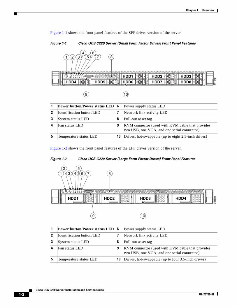
External Features OverviewThe figures in this chapter show an overview of external server features.
(Internal server features are illustrated in Figure 3-5 on page 3-9.)
The server is orderable in two different versions, each with one of two different front panel/backplane configurations:
• Cisco UCS C220 (small form-factor (SFF) drives, with 8-drive backplane. Holds up to eight 2.5-inch hard drives or solid state drives.
• Cisco UCS C220 (large form factor (LFF) drives, with 4-drive backplane). Holds up to four 3.5-inch hard drives.
1-2Cisco UCS C220 Server Installation and Service Guide
OL-25760-01
Chapter 1 Overview
Figure 1-1 shows the front panel features of the SFF drives version of the server.
Figure 1-1 Cisco UCS C220 Server (Small Form Factor Drives) Front Panel Features
Figure 1-2 shows the front panel features of the LFF drives version of the server.
Figure 1-2 Cisco UCS C220 Server (Large Form Factor Drives) Front Panel Features
1 Power button/Power status LED 6 Power supply status LED
2 Identification button/LED 7 Network link activity LED
3 System status LED 8 Pull-out asset tag
4 Fan status LED 9 KVM connector (used with KVM cable that provides two USB, one VGA, and one serial connector)
5 Temperature status LED 10 Drives, hot-swappable (up to eight 2.5-inch drives)
HDD4 HDD5HDD1HDD6
HDD2HDD7
HDD3HDD8
8
9 10
1 34
5 76
2
3316
82
1 Power button/Power status LED 6 Power supply status LED
2 Identification button/LED 7 Network link activity LED
3 System status LED 8 Pull-out asset tag
4 Fan status LED 9 KVM connector (used with KVM cable that provides two USB, one VGA, and one serial connector)
5 Temperature status LED 10 Drives, hot-swappable (up to four 3.5-inch drives)
HDD1 HDD2 HDD3 HDD4
109
84 6 75
312
3316
84
1-3Cisco UCS C220 Server Installation and Service Guide
OL-25760-01
Chapter 1 Overview
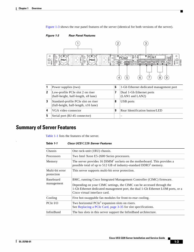
Figure 1-3 shows the rear panel features of the server (identical for both versions of the server).
Figure 1-3 Rear Panel Features
Summary of Server FeaturesTable 1-1 lists the features of the server.
.
1 Power supplies (two) 6 1-Gb Ethernet dedicated management port
2 Low-profile PCIe slot 2 on riser(half-height, half-length, x8 lane)
7 Dual 1-Gb Ethernet ports(LAN1 and LAN2)
3 Standard-profile PCIe slot on riser(full-height, half-length, x16 lane)
8 USB ports
4 VGA video connector 9 Rear Identification button/LED
5 Serial port (RJ-45 connector) –
PSU1PSU1 PSU2PSU2PSU1 PSU2PCIe2 PCIe1
4 5 6 98
2 31
7
3316
83
Table 1-1 Cisco UCS C220 Server Features
Chassis One rack-unit (1RU) chassis.
Processors Two Intel Xeon E5-2600 Series processors.
Memory The server provides 16 DIMM1 sockets on the motherboard. This provides a possible total of up to 512 GB of industry-standard DDR32 memory.
Multi-bit error protection
This server supports multi-bit error protection.
Baseboard management
BMC, running Cisco Integrated Management Controller (CIMC) firmware.
Depending on your CIMC settings, the CIMC can be accessed through the 1-Gb Ethernet dedicated management port, the dual 1-Gb Ethernet LOM ports, or a Cisco virtual interface card.
Cooling Five hot-swappable fan modules for front-to-rear cooling.
PCIe I/O Two horizontal PCIe3 expansion slots on risers. See Replacing a PCIe Card, page 3-35 for slot specifications.
InfiniBand The bus slots in this server support the InfiniBand architecture.
1-4Cisco UCS C220 Server Installation and Service Guide
OL-25760-01
Chapter 1 Overview
Network and management I/O
The server provides these rear-panel connectors:
• One 1-Gb Ethernet dedicated management port
• Two 1-Gb Base-T Ethernet ports
• One RS-232 serial port (RJ-45 connector)
• One 15-pin VGA4 connector
• Two USB5 2.0 connectors
• One front-panel KVM connector that is used with the included KVM cable, which provides two USB, one VGA, and one serial connector.
WoL The 1-Gb Base-T Ethernet LAN ports support the wake-on-LAN (WoL) standard.
Power Up to two power supplies, both either 450W or 650W each. Redundant as 1+1. Do not mix power supply types in the server.
See Power Specifications, page A-3 for more information on power supplies.
ACPI This server supports the advanced configuration and power interface (ACPI) 4.0 standard.
Storage Drives are installed into front-panel drive bays that provide hot-pluggable access. There are two versions of the server front panel and backplane:
• Small Form Factor—The server can hold up to eight 2.5-inch SAS6 or SATA7 hard drives or solid state drives.
• Large Form Factor—The server can hold up to four 3.5-inch SAS or SATA hard drives.
The server also contains one internal USB 2.0 port on the motherboard that you can use with a USB thumb drive for additional storage.
Cisco Flexible Flash drives
The server can be ordered with up to two optional Cisco Flexible Flash drives (SD cards).
This drive is pre-loaded with four virtual drives. The four virtual drives contain, respectively, the Cisco Server Configuration Utility, the Cisco Host Upgrade Utility, the Cisco C-Series server drivers set, and a blank virtual drive on which you can install an OS or a hypervisor (see also Replacing a Cisco Flexible Flash Card, page 3-40).
The two flash drives can be configured in a RAID 1 configuration to protect your hypervisor VD.
Disk Management(RAID)
For a list of supported RAID controller options, see RAID Controller Considerations, page C-1.
RAID Backup There is one mounting point inside the chassis that can be used for a RAID backup unit when using an LSI MegaRAID card. This unit can be either of the following:
• The optional LSI BBU that can be used with LSI MegaRAID cards.
• The SuperCap Power Module that can be used with LSI MegaRAID-CV cards.
Video Resolution up to 1600x1200, 16bpp at 60 Hz. Up to 256 MB of video memory.
1. DIMM = dual inline memory module
2. DDR3 = double data rate, type 3
3. PCIe = peripheral component interconnect express
4. VGA = video graphics array
5. USB = universal serial bus
Table 1-1 Cisco UCS C220 Server Features (continued)
1-5Cisco UCS C220 Server Installation and Service Guide
OL-25760-01
Chapter 1 Overview
6. SAS = serial attached SCSI
7. SATA = serial advanced technology attachment

1-6Cisco UCS C220 Server Installation and Service Guide
OL-25760-01
Chapter 1 Overview
C H A P T E R
2-1Cisco UCS C220 Server Installation and Service Guide
OL-25760-01
2Installing the Server
This chapter describes how to install the server, and it includes the following sections:
• Unpacking and Inspecting the Server, page 2-2
• Preparing for Server Installation, page 2-3
• Installing the Server In a Rack, page 2-5
• Initial Server Setup, page 2-9
• System BIOS and CIMC Firmware, page 2-13
• Updating the BIOS and CIMC Firmware, page 2-13
• Service Headers and Jumpers, page 2-15
Note Before you install, operate, or service a server, review the Regulatory Compliance and Safety Information for Cisco UCS C-Series Servers for important safety information.
Warning IMPORTANT SAFETY INSTRUCTIONSThis warning symbol means danger. You are in a situation that could cause bodily injury. Before you work on any equipment, be aware of the hazards involved with electrical circuitry and be familiar with standard practices for preventing accidents. Use the statement number provided at the end of each warning to locate its translation in the translated safety warnings that accompanied this device. Statement 1071
SAVE THESE INSTRUCTIONS
2-2Cisco UCS C220 Server Installation and Service Guide
OL-25760-01
Chapter 2 Installing the ServerUnpacking and Inspecting the Server
Unpacking and Inspecting the Server
Caution When handling internal server components, wear an ESD strap and handle modules by the carrier edges only.
Tip Keep the shipping container in case the server requires shipping in the future.
Note The chassis is thoroughly inspected before shipment. If any damage occurred during transportation or any items are missing, contact your customer service representative immediately.
To inspect the shipment, follow these steps:
Step 1 Remove the server from its cardboard container and save all packaging material.
Step 2 Compare the shipment to the equipment list provided by your customer service representative and Figure 2-1. Verify that you have all items.
Step 3 Check for damage and report any discrepancies or damage to your customer service representative. Have the following information ready:
• Invoice number of shipper (see the packing slip)
• Model and serial number of the damaged unit
• Description of damage
• Effect of damage on the installation
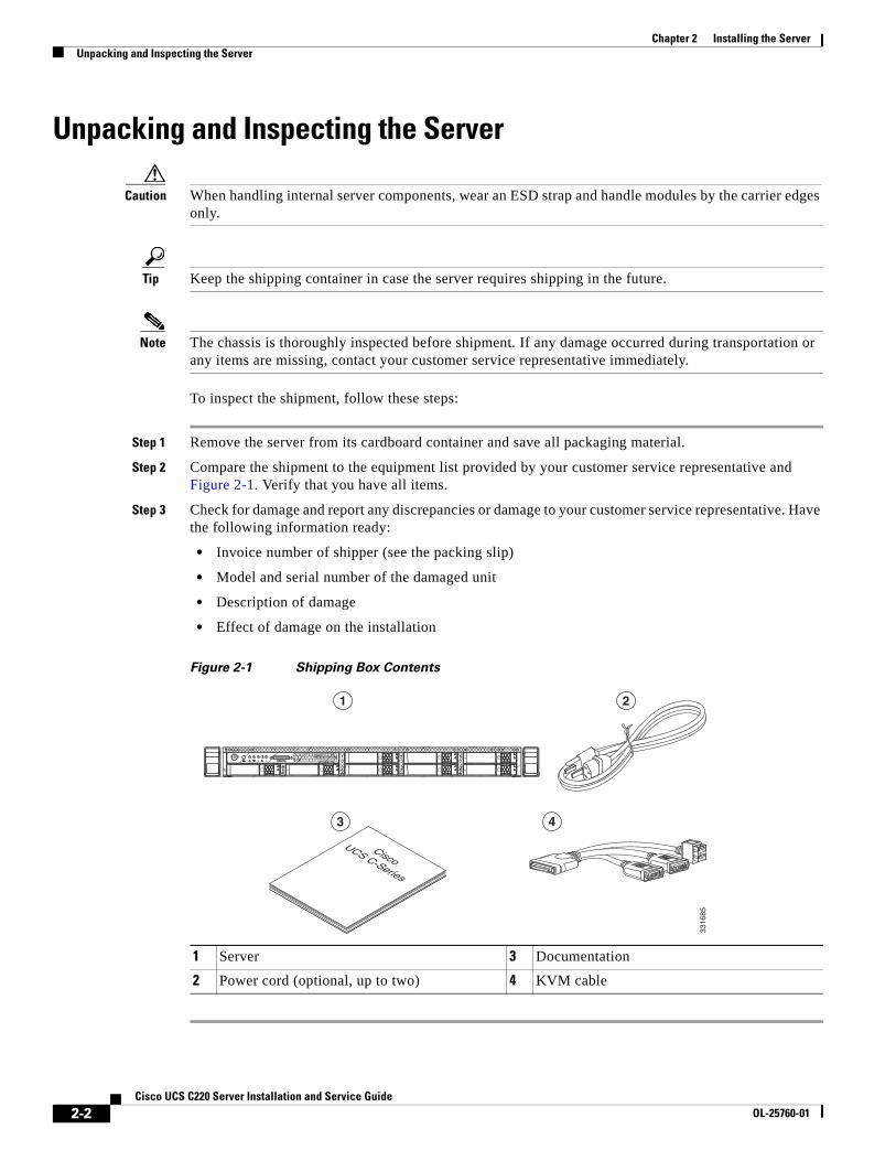
Figure 2-1 Shipping Box Contents
1 Server 3 Documentation
2 Power cord (optional, up to two) 4 KVM cable
CiscoUCS C-Series
1 2
3 4
3316
85
2-3Cisco UCS C220 Server Installation and Service Guide
OL-25760-01
Chapter 2 Installing the ServerPreparing for Server Installation
Preparing for Server InstallationThis section provides information about preparing for server installation, and it includes the following topics:
• Installation Guidelines, page 2-3
• Rack Requirements, page 2-4
• Equipment Requirements, page 2-4
• Slide Rail Adjustment Range, page 2-4
Installation Guidelines
Warning To prevent the system from overheating, do not operate it in an area that exceeds the maximum recommended ambient temperature of: 40° C (104° F). Statement 1047
Warning The plug-socket combination must be accessible at all times, because it serves as the main disconnecting device.Statement 1019
Warning This product relies on the building’s installation for short-circuit (overcurrent) protection. Ensure that the protective device is rated not greater than: 250 V, 15 A.Statement 1005
Warning Installation of the equipment must comply with local and national electrical codes.Statement 1074
Caution All Cisco UCS C-Series rack servers are shipped with rail kits and are expected to be rack-mounted. To ensure proper air flow it is necessary to rack the servers using the provided rail kits. Physically placing the units on top of one another or "stacking" without the use of the rail kits blocks the air vents on top of the servers, which could result in overheating, higher fan speeds, and higher power consumption. It is recommended that you mount your servers on the rail kits when installing them into the rack because these rails provide the minimal spacing required between the servers. No additional spacing between the servers is required when you mount the units using the provided rail kits.
Caution Avoid UPS types that use ferroresonant technology. These UPS types can become unstable with systems such as the Cisco UCS, which can have substantial current draw fluctuations from fluctuating data traffic patterns.
2-4Cisco UCS C220 Server Installation and Service Guide
OL-25760-01
Chapter 2 Installing the ServerPreparing for Server Installation
When you are installing a server, use the following guidelines:
• Plan your site configuration and prepare the site before installing the server. See the Cisco UCS Site Preparation Guide for the recommended site planning tasks.
• Ensure that there is adequate space around the server to allow for servicing the server and for adequate airflow. The airflow in this server is from front to back.
• Ensure that the air-conditioning meets the thermal requirements listed in the Server Specifications.
• Ensure that the cabinet or rack meets the requirements listed in the “Rack Requirements” section on page 2-4.
• Ensure that the site power meets the power requirements listed in the Server Specifications. If available, you can use an uninterruptible power supply (UPS) to protect against power failures.
Rack RequirementsThis section provides the requirements for the standard open racks.
The rack must be of the following type:
• A standard 19-in. (48.3-cm) wide, four-post EIA rack, with mounting posts that conform to English universal hole spacing, per section 1 of ANSI/EIA-310-D-1992.
• The rack post holes can be square 0.38-inch (9.6 mm), round 0.28-inch (7.1 mm), #12-24 UNC, or #10-32 UNC when you use the supplied slide rails.
• The minimum vertical rack space per server must be one RU, equal to 1.75 in. (44.45 mm).
Equipment RequirementsThe slide rails supplied by Cisco Systems for this server do not require tools for installation. The inner rails (mounting brackets) are pre-attached to the sides of the server.
Slide Rail Adjustment RangeThe slide rails for this server have an adjustment range of 24 to 36 inches (610 to 914 mm).
2-5Cisco UCS C220 Server Installation and Service Guide
OL-25760-01
Chapter 2 Installing the ServerInstalling the Server In a Rack
Installing the Server In a RackThis section describes how to install the server in a rack.
Warning To prevent bodily injury when mounting or servicing this unit in a rack, you must take special precautions to ensure that the system remains stable. The following guidelines are provided to ensure your safety:This unit should be mounted at the bottom of the rack if it is the only unit in the rack.When mounting this unit in a partially filled rack, load the rack from the bottom to the top with the heaviest component at the bottom of the rack.If the rack is provided with stabilizing devices, install the stabilizers before mounting or servicing the unit in the rack. Statement 1006
To install the slide rails and the server into a rack, follow these steps:
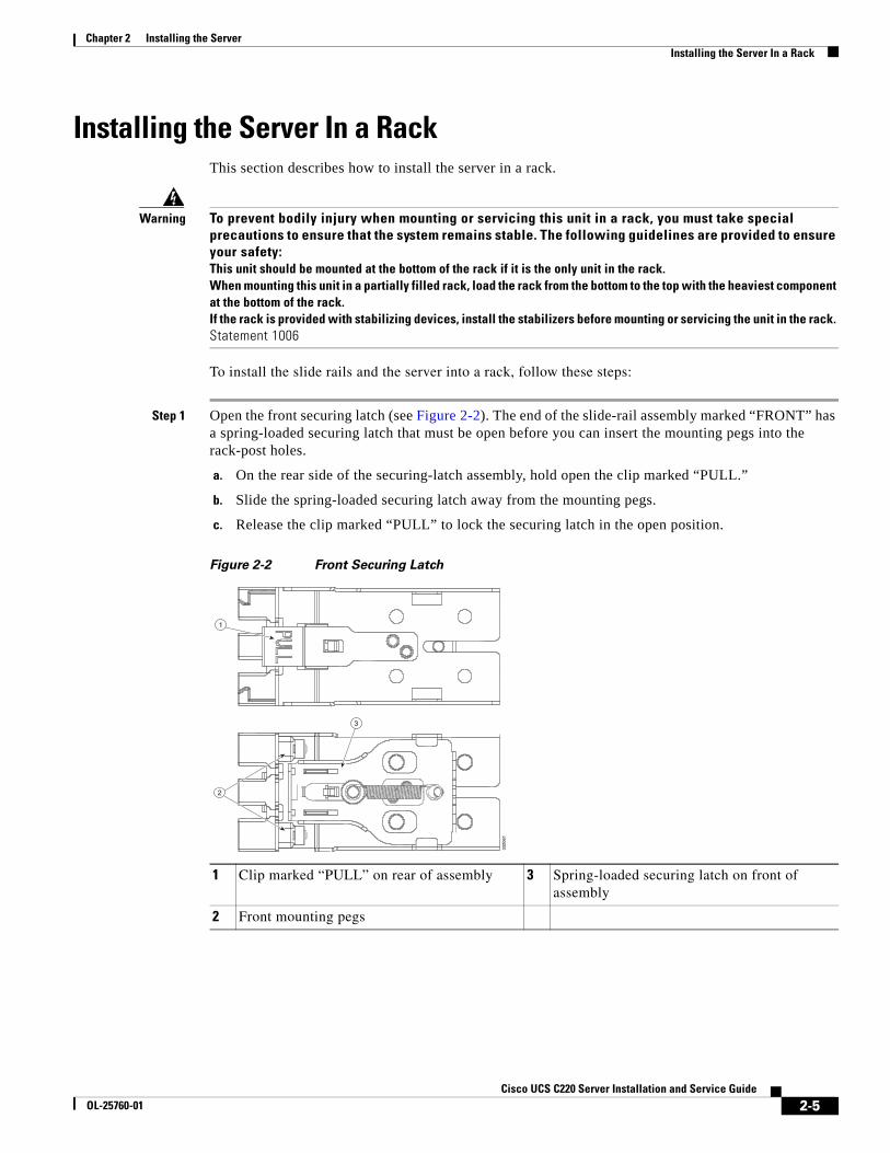
Step 1 Open the front securing latch (see Figure 2-2). The end of the slide-rail assembly marked “FRONT” has a spring-loaded securing latch that must be open before you can insert the mounting pegs into the rack-post holes.
a. On the rear side of the securing-latch assembly, hold open the clip marked “PULL.”
b. Slide the spring-loaded securing latch away from the mounting pegs.
c. Release the clip marked “PULL” to lock the securing latch in the open position.
Figure 2-2 Front Securing Latch
1 Clip marked “PULL” on rear of assembly 3 Spring-loaded securing latch on front of assembly
2 Front mounting pegs
3
1
2
3320
61
2-6Cisco UCS C220 Server Installation and Service Guide
OL-25760-01
Chapter 2 Installing the ServerInstalling the Server In a Rack
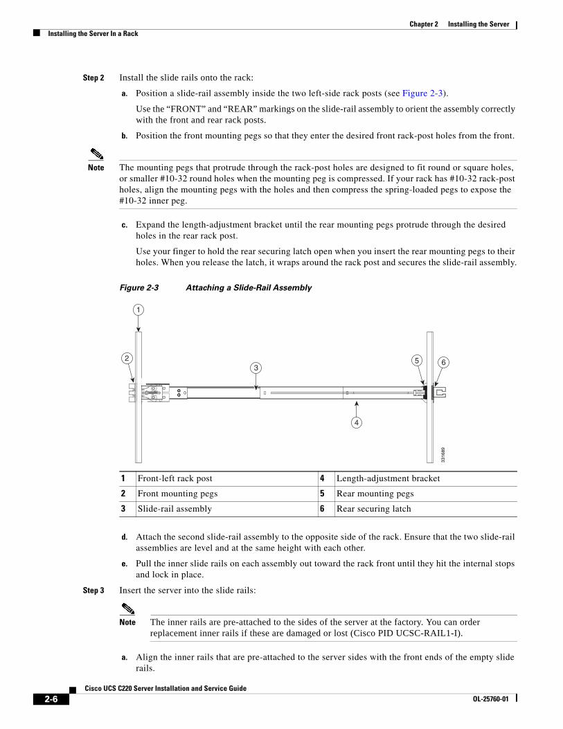
Step 2 Install the slide rails onto the rack:
a. Position a slide-rail assembly inside the two left-side rack posts (see Figure 2-3).
Use the “FRONT” and “REAR” markings on the slide-rail assembly to orient the assembly correctly with the front and rear rack posts.
b. Position the front mounting pegs so that they enter the desired front rack-post holes from the front.
Note The mounting pegs that protrude through the rack-post holes are designed to fit round or square holes, or smaller #10-32 round holes when the mounting peg is compressed. If your rack has #10-32 rack-post holes, align the mounting pegs with the holes and then compress the spring-loaded pegs to expose the #10-32 inner peg.
c. Expand the length-adjustment bracket until the rear mounting pegs protrude through the desired holes in the rear rack post.
Use your finger to hold the rear securing latch open when you insert the rear mounting pegs to their holes. When you release the latch, it wraps around the rack post and secures the slide-rail assembly.
Figure 2-3 Attaching a Slide-Rail Assembly
d. Attach the second slide-rail assembly to the opposite side of the rack. Ensure that the two slide-rail assemblies are level and at the same height with each other.
e. Pull the inner slide rails on each assembly out toward the rack front until they hit the internal stops and lock in place.
Step 3 Insert the server into the slide rails:
Note The inner rails are pre-attached to the sides of the server at the factory. You can order replacement inner rails if these are damaged or lost (Cisco PID UCSC-RAIL1-I).
a. Align the inner rails that are pre-attached to the server sides with the front ends of the empty slide rails.
1 Front-left rack post 4 Length-adjustment bracket
2 Front mounting pegs 5 Rear mounting pegs
3 Slide-rail assembly 6 Rear securing latch
3316
89
1
32 5 6
4
2-7Cisco UCS C220 Server Installation and Service Guide
OL-25760-01
Chapter 2 Installing the ServerInstalling the Server In a Rack
b. Push the server into the slide rails until it stops at the internal stops.
c. Push in the plastic release clip on each inner rail (labelled PUSH), and then continue pushing the server into the rack until its front latches engage the rack posts.
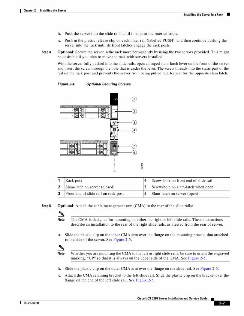
Step 4 Optional: Secure the server in the rack more permanently by using the two screws provided. This might be desirable if you plan to move the rack with servers installed.
With the server fully pushed into the slide rails, open a hinged slam-latch lever on the front of the server and insert the screw through the hole that is under the lever. The screw threads into the static part of the rail on the rack post and prevents the server from being pulled out. Repeat for the opposite slam latch.
Figure 2-4 Optional Securing Screws
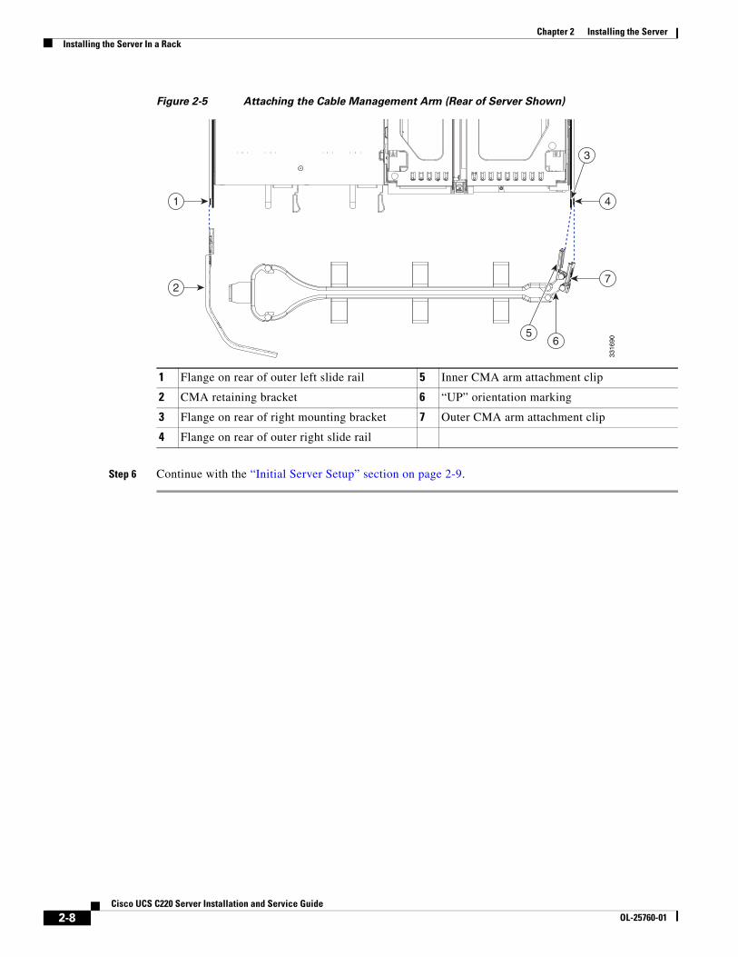
Step 5 Optional: Attach the cable management arm (CMA) to the rear of the slide rails:
Note The CMA is designed for mounting on either the right or left slide rails. These instructions describe an installation to the rear of the right slide rails, as viewed from the rear of server.
a. Slide the plastic clip on the inner CMA arm over the flange on the mounting bracket that attached to the side of the server. See Figure 2-5.
Note Whether you are mounting the CMA to the left or right slide rails, be sure to orient the engraved marking, “UP” so that it is always on the upper side of the CMA. See Figure 2-5.
b. Slide the plastic clip on the outer CMA arm over the flange on the slide rail. See Figure 2-5.
c. Attach the CMA retaining bracket to the left slide rail. Slide the plastic clip on the bracket over the flange on the end of the left slide rail. See Figure 2-5.
1 Rack post 4 Screw-hole on front end of slide rail
2 Slam-latch on server (closed) 5 Screw-hole on slam-latch when open
3 Front end of slide rail on rack-post 6 Slam-latch on server (open)
2-8Cisco UCS C220 Server Installation and Service Guide
OL-25760-01
Chapter 2 Installing the ServerInstalling the Server In a Rack
Figure 2-5 Attaching the Cable Management Arm (Rear of Server Shown)
Step 6 Continue with the “Initial Server Setup” section on page 2-9.
1 Flange on rear of outer left slide rail 5 Inner CMA arm attachment clip
2 CMA retaining bracket 6 “UP” orientation marking
3 Flange on rear of right mounting bracket 7 Outer CMA arm attachment clip
4 Flange on rear of outer right slide rail
7
3316
9065
4
3
1
2
2-9Cisco UCS C220 Server Installation and Service Guide
OL-25760-01
Chapter 2 Installing the ServerInitial Server Setup
Initial Server Setup This section includes the following topics:
• Connecting and Powering On the Server (Standalone Mode), page 2-9
• NIC Modes and NIC Redundancy Settings, page 2-12
Connecting and Powering On the Server (Standalone Mode)
Note This section describes how to power on the server, assign an IP address, and connect to server management when using the server in standalone mode. To use the server in UCS integration, specific cabling and settings are required. See Installation for Cisco UCS Integration, page D-1.
Note The server is shipped with a default NIC mode called Shared LOM EXT, default NIC redundancy is active-active, and DHCP is enabled. Shared LOM EXT mode enables the 1-Gb Ethernet ports and the ports on any installed Cisco virtual interface card (VIC) to access the Cisco Integrated Management Interface (CIMC). If you want to use the dedicated management ports to access the CIMC, you can connect to the server and change the NIC mode as described in Step 3 of the following procedure. In that step, you can also change the NIC redundancy and set static IP settings.
Use the following procedure to perform initial setup of the server:
Step 1 Attach a supplied power cord to each power supply in your server, and then attach the power cord to a grounded AC power outlet. See the Power Specifications, page A-3 for power specifications.
Wait for approximately two minutes to let the server boot in standby power during the first bootup.
You can verify power status by looking at the Power Status LED (see Figure 1-1 on page 1-2):
• Off—There is no AC power present in the server.
• Amber—The server is in standby power mode. Power is supplied only to the CIMC and some motherboard functions.
• Green—The server is in main power mode. Power is supplied to all server components.
Note During bootup, the server beeps once for each USB device that is attached to the server. Even if there are no external USB devices attached, there is a short beep for each virtual USB device such as a virtual floppy drive, CD/DVD drive, keyboard, or mouse. A beep is also emitted if a USB device is hot-plugged or hot-unplugged during BIOS power-on self test (POST), or while you are accessing the BIOS Setup utility or the EFI shell.
Step 2 Connect a USB keyboard and VGA monitor by using the supplied KVM cable connected to the KVM connector on the front panel (see Figure 1-1 on page 1-2).
Note Alternatively, you can use the VGA and USB ports on the rear panel. However, you cannot use the front panel VGA and the rear panel VGA at the same time. If you are connected to one VGA connector and you then connect a video device to the other connector, the first VGA connector is disabled.
2-10Cisco UCS C220 Server Installation and Service Guide
OL-25760-01
Chapter 2 Installing the ServerInitial Server Setup
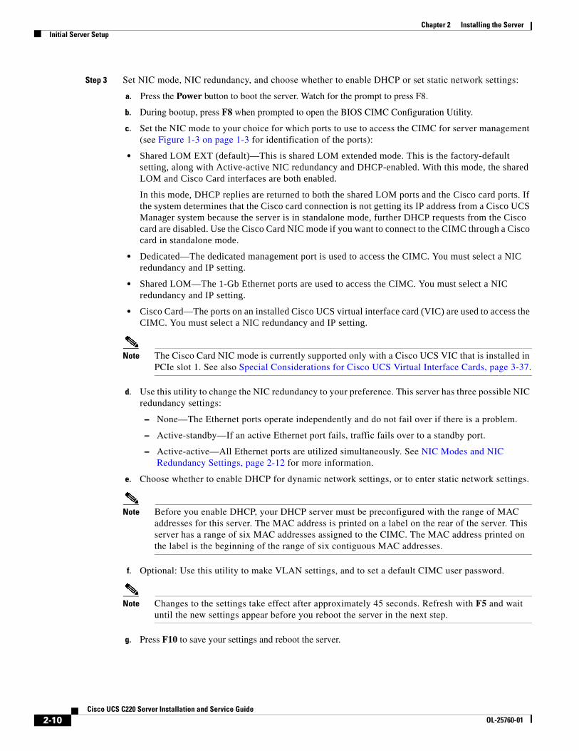
Step 3 Set NIC mode, NIC redundancy, and choose whether to enable DHCP or set static network settings:
a. Press the Power button to boot the server. Watch for the prompt to press F8.
b. During bootup, press F8 when prompted to open the BIOS CIMC Configuration Utility.
c. Set the NIC mode to your choice for which ports to use to access the CIMC for server management (see Figure 1-3 on page 1-3 for identification of the ports):
• Shared LOM EXT (default)—This is shared LOM extended mode. This is the factory-default setting, along with Active-active NIC redundancy and DHCP-enabled. With this mode, the shared LOM and Cisco Card interfaces are both enabled.
In this mode, DHCP replies are returned to both the shared LOM ports and the Cisco card ports. If the system determines that the Cisco card connection is not getting its IP address from a Cisco UCS Manager system because the server is in standalone mode, further DHCP requests from the Cisco card are disabled. Use the Cisco Card NIC mode if you want to connect to the CIMC through a Cisco card in standalone mode.
• Dedicated—The dedicated management port is used to access the CIMC. You must select a NIC redundancy and IP setting.
• Shared LOM—The 1-Gb Ethernet ports are used to access the CIMC. You must select a NIC redundancy and IP setting.
• Cisco Card—The ports on an installed Cisco UCS virtual interface card (VIC) are used to access the CIMC. You must select a NIC redundancy and IP setting.
Note The Cisco Card NIC mode is currently supported only with a Cisco UCS VIC that is installed in PCIe slot 1. See also Special Considerations for Cisco UCS Virtual Interface Cards, page 3-37.
d. Use this utility to change the NIC redundancy to your preference. This server has three possible NIC redundancy settings:
– None—The Ethernet ports operate independently and do not fail over if there is a problem.
– Active-standby—If an active Ethernet port fails, traffic fails over to a standby port.
– Active-active—All Ethernet ports are utilized simultaneously. See NIC Modes and NIC Redundancy Settings, page 2-12 for more information.
e. Choose whether to enable DHCP for dynamic network settings, or to enter static network settings.
Note Before you enable DHCP, your DHCP server must be preconfigured with the range of MAC addresses for this server. The MAC address is printed on a label on the rear of the server. This server has a range of six MAC addresses assigned to the CIMC. The MAC address printed on the label is the beginning of the range of six contiguous MAC addresses.
f. Optional: Use this utility to make VLAN settings, and to set a default CIMC user password.
Note Changes to the settings take effect after approximately 45 seconds. Refresh with F5 and wait until the new settings appear before you reboot the server in the next step.
g. Press F10 to save your settings and reboot the server.
2-11Cisco UCS C220 Server Installation and Service Guide
OL-25760-01
Chapter 2 Installing the ServerInitial Server Setup
Note If you chose to enable DHCP, the dynamically assigned IP and MAC addresses are displayed on the console screen during bootup.
Step 4 Connect to the CIMC for server management. Connect Ethernet cables from your LAN to the server, using the ports that you selected by your NIC Mode setting in Step 3. The Active-active and Active-passive NIC redundancy settings require you to connect to two ports.
Step 5 Use a browser and the IP address of the CIMC to connect to the CIMC Setup Utility. The IP address is based upon the settings that you made in Step 3 (either a static address or the address assigned by your DHCP server).
Note The default user name for the server is admin. The default password is password.
To manage the server, see the Cisco UCS C-Series Rack-Mount Server Configuration Guide or the Cisco UCS C-Series Rack-Mount Server CLI Configuration Guide for instructions on using those interfaces. The links to these documents are in the C-Series documentation roadmap:
http://www.cisco.com/go/unifiedcomputing/c-series-doc
2-12Cisco UCS C220 Server Installation and Service Guide
OL-25760-01
Chapter 2 Installing the ServerInitial Server Setup
NIC Modes and NIC Redundancy SettingsThis server has the following NIC mode settings that you can choose from:
• Shared LOM EXT (default)—This is shared LOM extended mode. This is the factory-default setting, along with Active-active NIC redundancy and DHCP-enabled. With this mode, the shared LOM and Cisco Card interfaces are both enabled.
In this mode, DHCP replies are returned to both the shared LOM ports and the Cisco card ports. If the system determines that the Cisco card connection is not getting its IP address from a Cisco UCS Manager system because the server is in standalone mode, further DHCP requests from the Cisco card are disabled. If the system determines that the Cisco card connection is getting its IP address from a Cisco UCS Manager system, the reply has parameters that automatically move the server to UCSM mode.
• Dedicated—The dedicated management port is used to access the CIMC. You must select a NIC redundancy and IP setting.
• Shared LOM—The 1-Gb Ethernet ports are used to access the CIMC. You must select a NIC redundancy and IP setting.
• Cisco Card—The ports on an installed Cisco UCS virtual interface card (VIC) are used to access the CIMC. You must select a NIC redundancy and IP setting.
Note The Cisco Card NIC mode is currently supported only with a Cisco UCS VIC that is installed in PCIe slot 1. See also Special Considerations for Cisco UCS Virtual Interface Cards, page 3-37.
This server has the following NIC redundancy settings that you can choose from:
• None—The Ethernet ports operate independently and do not fail over if there is a problem.
• Active-standby—If an active Ethernet port fails, traffic fails over to a standby port.
• Active-active—All Ethernet ports are utilized simultaneously.
The active/active setting uses Mode 5 or Balance-TLB (adaptive transmit load balancing). This is channel bonding that does not require any special switch support. The outgoing traffic is distributed according to the current load (computed relative to the speed) on each slave. Incoming traffic is received by the current slave. If the receiving slave fails, another slave takes over the MAC address of the failed receiving slave.
2-13Cisco UCS C220 Server Installation and Service Guide
OL-25760-01
Chapter 2 Installing the ServerSystem BIOS and CIMC Firmware
System BIOS and CIMC FirmwareThis section includes information about the system BIOS and it includes the following sections:
• Updating the BIOS and CIMC Firmware, page 2-13
• Accessing the System BIOS, page 2-14
Updating the BIOS and CIMC Firmware
Caution When you upgrade the BIOS firmware, you must also upgrade the CIMC firmware to the same version or the server will not boot. Do not power off the server until the BIOS and CIMC firmware are matching or the server will not boot.Cisco provides the Cisco Host Upgrade Utility to assist with simultaneously upgrading the BIOS, CIMC, and other firmware to compatible levels.
The server uses firmware obtained from and certified by Cisco. Cisco provides release notes with each firmware image. There are several methods for updating the firmware:
• Recommended method for systems running firmware level 1.2 or later: Use the Cisco Host Upgrade Utility to simultaneously upgrade the CIMC, BIOS, LOM, LSI storage controller, and Cisco UCS P81E VIC firmware to compatible levels.
See the Cisco Host Upgrade Utility Quick Reference Guide for your firmware level at the documentation roadmap link below.
Note Your system firmware must be at minimum level 1.2 to use the Cisco Host Upgrade Utility. If your firmware is prior to level 1.2, you must use the methods below to update the BIOS and CIMC firmware individually.
• You can upgrade the BIOS using the EFI interface, or upgrade from a Windows or Linux platform.
See the Cisco UCS C-Series Rack-Mount Server BIOS Upgrade Guide.
• You can upgrade the CIMC and BIOS firmware by using the CIMC GUI interface.
See the Cisco UCS C-Series Rack-Mount Server Configuration Guide.
• You can upgrade the CIMC and BIOS firmware by using the CIMC CLI interface.
See the Cisco UCS C-Series Rack-Mount Server CLI Configuration Guide.
For links to the documents listed above, see the documentation roadmap at the following URL:
http://www.cisco.com/go/unifiedcomputing/c-series-doc
2-14Cisco UCS C220 Server Installation and Service Guide
OL-25760-01
Chapter 2 Installing the ServerSystem BIOS and CIMC Firmware
Accessing the System BIOS To change the BIOS settings for your server, follow these steps. Detailed instructions are also printed on the BIOS screens.
Step 1 Enter the BIOS setup utility by pressing the F2 key when prompted during bootup.
Note The version and build of the current BIOS are displayed on the Main page of the utility.
Step 2 Use the arrow keys to select the BIOS menu page.
Step 3 Highlight the field to be modified by using the arrow keys.
Step 4 Press Enter to select the field that you want to change, and then modify the value in the field.
Step 5 Press the right arrow key until the Exit menu screen is displayed.
Step 6 Follow the instructions on the Exit menu screen to save your changes and exit the setup utility (or Press F10). You can exit without saving changes by pressing Esc.
2-15Cisco UCS C220 Server Installation and Service Guide
OL-25760-01
Chapter 2 Installing the ServerService Headers and Jumpers
Service Headers and JumpersThis section includes the following topics:
• Header Locations on the Motherboard, page 2-15
• Using the BIOS Recovery Header J41, page 2-16
• Using the Clear CMOS Header J37, page 2-19
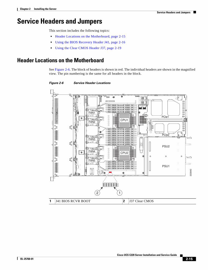
Header Locations on the MotherboardSee Figure 2-6. The block of headers is shown in red. The individual headers are shown in the magnified view. The pin numbering is the same for all headers in the block.
Figure 2-6 Service Header Locations
1 J41 BIOS RCVR BOOT 2 J37 Clear CMOS
FAN1
FAN2
FAN3
FAN4FAN4
FAN5
PSU2
PCIe1
PCIe2
PSU1
CPU1
CPU2
3339
40
12
3
12
2-16Cisco UCS C220 Server Installation and Service Guide
OL-25760-01
Chapter 2 Installing the ServerService Headers and Jumpers
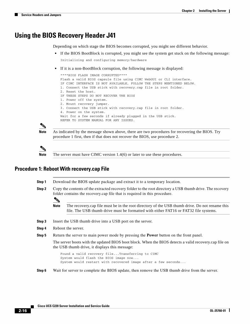
Using the BIOS Recovery Header J41Depending on which stage the BIOS becomes corrupted, you might see different behavior.
• If the BIOS BootBlock is corrupted, you might see the system get stuck on the following message:
Initializing and configuring memory/hardware
• If it is a non-BootBlock corruption, the following message is displayed:
****BIOS FLASH IMAGE CORRUPTED****Flash a valid BIOS capsule file using CIMC WebGUI or CLI interface.IF CIMC INTERFACE IS NOT AVAILABLE, FOLLOW THE STEPS MENTIONED BELOW.1. Connect the USB stick with recovery.cap file in root folder.2. Reset the host.IF THESE STEPS DO NOT RECOVER THE BIOS1. Power off the system.2. Mount recovery jumper.3. Connect the USB stick with recovery.cap file in root folder.4. Power on the system.Wait for a few seconds if already plugged in the USB stick.REFER TO SYSTEM MANUAL FOR ANY ISSUES.
Note As indicated by the message shown above, there are two procedures for recovering the BIOS. Try procedure 1 first, then if that does not recover the BIOS, use procedure 2.
Note The server must have CIMC version 1.4(6) or later to use these procedures.
Procedure 1: Reboot With recovery.cap File
Step 1 Download the BIOS update package and extract it to a temporary location.
Step 2 Copy the contents of the extracted recovery folder to the root directory a USB thumb drive. The recovery folder contains the recovery.cap file that is required in this procedure.
Note The recovery.cap file must be in the root directory of the USB thumb drive. Do not rename this file. The USB thumb drive must be formatted with either FAT16 or FAT32 file systems.
Step 3 Insert the USB thumb drive into a USB port on the server.
Step 4 Reboot the server.
Step 5 Return the server to main power mode by pressing the Power button on the front panel.
The server boots with the updated BIOS boot block. When the BIOS detects a valid recovery.cap file on the USB thumb drive, it displays this message:
Found a valid recovery file...Transferring to CIMCSystem would flash the BIOS image now...System would restart with recovered image after a few seconds...
Step 6 Wait for server to complete the BIOS update, then remove the USB thumb drive from the server.
2-17Cisco UCS C220 Server Installation and Service Guide
OL-25760-01
Chapter 2 Installing the ServerService Headers and Jumpers
Note During the BIOS update, the CIMC will shut down the server and the screen will be blank for about 10 minutes. Do not unplug the power cords during this update. The CIMC will power on the server after the update is complete.
2-18Cisco UCS C220 Server Installation and Service Guide
OL-25760-01
Chapter 2 Installing the ServerService Headers and Jumpers
Procedure 2: Use Recovery Jumper and recovery.cap File
See Figure 2-6 for the location of the J41 header.
Step 1 Download the BIOS update package and extract it to a temporary location.
Step 2 Copy the contents of the extracted recovery folder to the root directory a USB thumb drive. The recovery folder contains the recovery.cap file that is required in this procedure.
Note The recovery.cap file must be in the root directory of the USB thumb drive. Do not rename this file. The USB thumb drive must be formatted with either FAT16 or FAT32 file systems.
Step 3 Power off the server as described in Shutting Down and Powering Off the Server, page 3-7.
Step 4 Disconnect all power cords from the power supplies.
Step 5 Slide the server out the front of the rack far enough so that you can remove the top cover. You might have to detach cables from the rear panel to provide clearance.
Caution If you cannot safely view and access the component, remove the server from the rack.
Step 6 Remove the top cover as described in Removing and Replacing the Server Top Cover, page 3-8.
Step 7 Move the shorting jumper to pins 2 and 3 of the J41 header (see Figure 2-6).
Step 8 Reconnect AC power cords to the server. The server powers up to standby power mode.
Step 9 Insert the USB thumb drive that you prepared in Step 2 into a USB port on the server.
Step 10 Return the server to main power mode by pressing the Power button on the front panel.
The server boots with the updated BIOS boot block. When the BIOS detects a valid recovery.cap file on the USB thumb drive, it displays this message:
Found a valid recovery file...Transferring to CIMCSystem would flash the BIOS image now...System would restart with recovered image after a few seconds...
Step 11 Wait for server to complete the BIOS update, then remove the USB thumb drive from the server.
Note During the BIOS update, the CIMC will shut down the server and the screen will be blank for about 10 minutes. Do not unplug the power cords during this update. The CIMC will power on the server after the update is complete.
Step 12 After the server has fully booted, power off the server again and disconnect all power cords.
Step 13 Move the jumper back to the default pins 1 and 2 of the J41 header.
Note If you do not move the jumper, after recovery completion you see the prompt, Please remove the recovery jumper.
Step 14 Replace the top cover, replace the server in the rack, replace power cords and any other cables, then power on the server by pressing the Power button.
2-19Cisco UCS C220 Server Installation and Service Guide
OL-25760-01
Chapter 2 Installing the ServerService Headers and Jumpers
Using the Clear CMOS Header J37See Figure 2-6 for the location of this header. You can jumper this header to clear the server’s CMOS settings in the case of a system hang. For example, if the server hangs because of incorrect settings and does not boot, use this jumper to invalidate the settings and reboot with defaults.
Caution Clearing the CMOS removes any customized settings and might result in data loss. Make a note of any necessary customized settings in the BIOS before you use this clear CMOS procedure.
Step 1 Power off the server as described in Shutting Down and Powering Off the Server, page 3-7.
Step 2 Disconnect all power cords from the power supplies.
Step 3 Slide the server out the front of the rack far enough so that you can remove the top cover. You might have to detach cables from the rear panel to provide clearance.
Caution If you cannot safely view and access the component, remove the server from the rack.
Step 4 Remove the top cover as described in Removing and Replacing the Server Top Cover, page 3-8.
Step 5 Move the shorting jumper to pins 2 and 3 of the J37 header (see Figure 2-6).
Step 6 Reinstall the top cover and reconnect AC power cords to the server. The server powers up to standby power mode, indicated when the Power LED on the front panel is amber.
Step 7 Return the server to main power mode by pressing the Power button on the front panel. The server is in main power mode when the Power LED is green.
Note You must allow the entire server, not just the service processor, to reboot to main power mode to complete the reset. This is because the state of the jumper cannot be determined without the host CPU running.
Step 8 Press the Power button to shut down the server to standby power mode, and then remove AC power cords from the server to remove all power.
Step 9 Remove the top cover from the server.
Step 10 Move the shorting jumper from header pins 2 and 3, back to its default position on pins 1 and 2.
Note If you do not move the jumper, the CMOS settings are reset to the default every time that you power-cycle the server.
Step 11 Replace the top cover, replace the server in the rack, replace power cords and any other cables, then power on the server by pressing the Power button.

2-20Cisco UCS C220 Server Installation and Service Guide
OL-25760-01
Chapter 2 Installing the ServerService Headers and Jumpers
C H A P T E R
3-1Cisco UCS C220 Server Installation and Service Guide
OL-25760-01
3Maintaining the Server
This chapter describes how to diagnose server system problems using LEDs. It also provides information about how to install or replace hardware components, and it includes the following sections:
• Server Monitoring and Management Tools, page 3-1
• Status LEDs and Buttons, page 3-2
• Preparing for Server Component Installation, page 3-7
• Installing or Replacing Server Components, page 3-11
Server Monitoring and Management Tools
Cisco Integrated Management Interface (CIMC)You can monitor the server inventory, health, and system event logs by using the built-in Cisco Integrated Management Controller (CIMC) GUI or CLI interfaces. See the user documentation for your firmware release at the following URL:
http://www.cisco.com/en/US/products/ps10739/products_installation_and_configuration_guides_list.html
Server Configuration UtilityCisco has also developed the Cisco Server Configuration Utility for C-Series servers, which can aid and simplify the following tasks:
• Monitoring server inventory and health
• Diagnosing common server problems with diagnostic tools and logs
• Setting the BIOS booting order
• Configuring some RAID configurations
• Installing operating systems
This utility is pre-installed on an internal Cisco Flexible Flash card inside the server (see Overview of the Pre-Installed Cisco Flexible Flash Card, page 3-40). You can also download the ISO from Cisco.com. See the user documentation for your version of the utility at the following URL:
http://www.cisco.com/en/US/products/ps10493/products_user_guide_list.html
3-2Cisco UCS C220 Server Installation and Service Guide
OL-25760-01
Chapter 3 Maintaining the ServerStatus LEDs and Buttons
Status LEDs and ButtonsThis section describes the location and meaning of LEDs and buttons and includes the following topics
• Front Panel LEDs, page 3-2
• Rear Panel LEDs and Buttons, page 3-4
• Internal Diagnostic LEDs, page 3-6
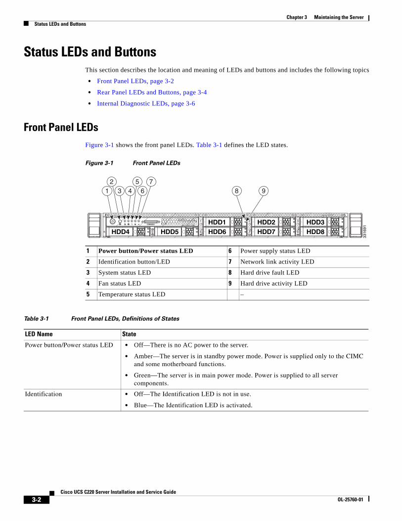
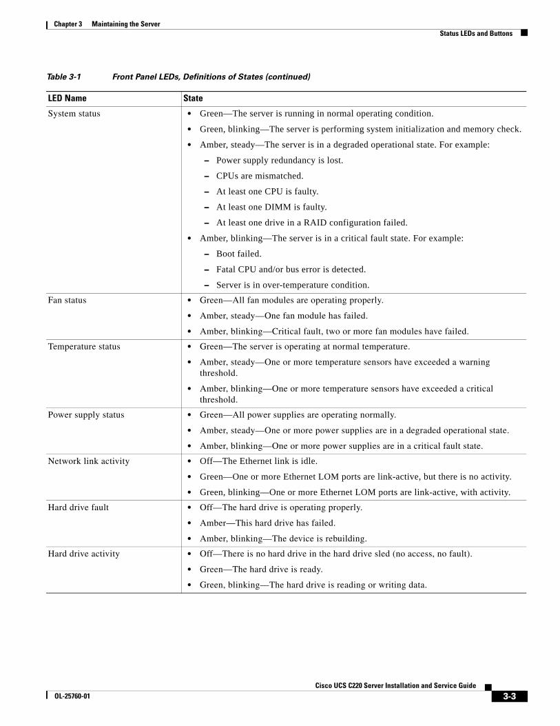
Front Panel LEDsFigure 3-1 shows the front panel LEDs. Table 3-1 defines the LED states.
Figure 3-1 Front Panel LEDs
1 Power button/Power status LED 6 Power supply status LED
2 Identification button/LED 7 Network link activity LED
3 System status LED 8 Hard drive fault LED
4 Fan status LED 9 Hard drive activity LED
5 Temperature status LED –
Table 3-1 Front Panel LEDs, Definitions of States
LED Name State
Power button/Power status LED • Off—There is no AC power to the server.
• Amber—The server is in standby power mode. Power is supplied only to the CIMC and some motherboard functions.
• Green—The server is in main power mode. Power is supplied to all server components.
Identification • Off—The Identification LED is not in use.
• Blue—The Identification LED is activated.
HDD4 HDD5HDD1HDD6
HDD2HDD7
HDD3HDD8
8 91 3 4 6752
3316
91
3-3Cisco UCS C220 Server Installation and Service Guide
OL-25760-01
Chapter 3 Maintaining the ServerStatus LEDs and Buttons
System status • Green—The server is running in normal operating condition.
• Green, blinking—The server is performing system initialization and memory check.
• Amber, steady—The server is in a degraded operational state. For example:
– Power supply redundancy is lost.
– CPUs are mismatched.
– At least one CPU is faulty.
– At least one DIMM is faulty.
– At least one drive in a RAID configuration failed.
• Amber, blinking—The server is in a critical fault state. For example:
– Boot failed.
– Fatal CPU and/or bus error is detected.
– Server is in over-temperature condition.
Fan status • Green—All fan modules are operating properly.
• Amber, steady—One fan module has failed.
• Amber, blinking—Critical fault, two or more fan modules have failed.
Temperature status • Green—The server is operating at normal temperature.
• Amber, steady—One or more temperature sensors have exceeded a warning threshold.
• Amber, blinking—One or more temperature sensors have exceeded a critical threshold.
Power supply status • Green—All power supplies are operating normally.
• Amber, steady—One or more power supplies are in a degraded operational state.
• Amber, blinking—One or more power supplies are in a critical fault state.
Network link activity • Off—The Ethernet link is idle.
• Green—One or more Ethernet LOM ports are link-active, but there is no activity.
• Green, blinking—One or more Ethernet LOM ports are link-active, with activity.
Hard drive fault • Off—The hard drive is operating properly.
• Amber—This hard drive has failed.
• Amber, blinking—The device is rebuilding.
Hard drive activity • Off—There is no hard drive in the hard drive sled (no access, no fault).
• Green—The hard drive is ready.
• Green, blinking—The hard drive is reading or writing data.
Table 3-1 Front Panel LEDs, Definitions of States (continued)
LED Name State
3-4Cisco UCS C220 Server Installation and Service Guide
OL-25760-01
Chapter 3 Maintaining the ServerStatus LEDs and Buttons
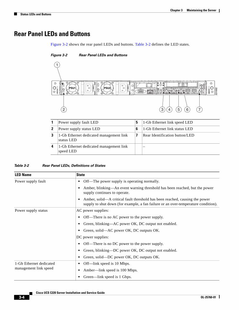
Rear Panel LEDs and ButtonsFigure 3-2 shows the rear panel LEDs and buttons. Table 3-2 defines the LED states.
Figure 3-2 Rear Panel LEDs and Buttons
1 Power supply fault LED 5 1-Gb Ethernet link speed LED
2 Power supply status LED 6 1-Gb Ethernet link status LED
3 1-Gb Ethernet dedicated management link status LED
7 Rear Identification button/LED
4 1-Gb Ethernet dedicated management link speed LED
–
Table 3-2 Rear Panel LEDs, Definitions of States
LED Name State
Power supply fault • Off—The power supply is operating normally.
• Amber, blinking—An event warning threshold has been reached, but the power supply continues to operate.
• Amber, solid—A critical fault threshold has been reached, causing the power supply to shut down (for example, a fan failure or an over-temperature condition).
Power supply status AC power supplies:
• Off—There is no AC power to the power supply.
• Green, blinking—AC power OK, DC output not enabled.
• Green, solid—AC power OK, DC outputs OK.
DC power supplies:
• Off—There is no DC power to the power supply.
• Green, blinking—DC power OK, DC output not enabled.
• Green, solid—DC power OK, DC outputs OK.
1-Gb Ethernet dedicated management link speed
• Off—link speed is 10 Mbps.
• Amber—link speed is 100 Mbps.
• Green—link speed is 1 Gbps.
PSU1PSU1 PSU2PSU2PSU1 PSU2
1
2 3 4 75 6
3316
92
3-5Cisco UCS C220 Server Installation and Service Guide
OL-25760-01
Chapter 3 Maintaining the ServerStatus LEDs and Buttons
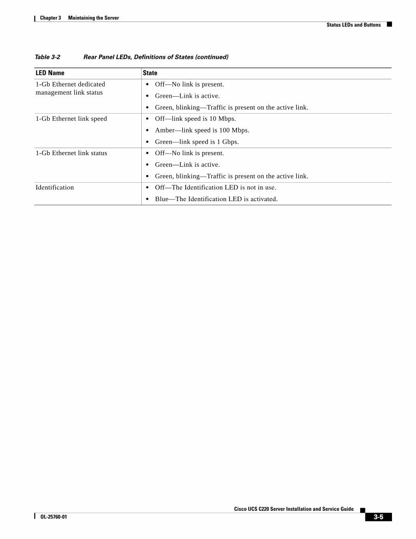
1-Gb Ethernet dedicated management link status
• Off—No link is present.
• Green—Link is active.
• Green, blinking—Traffic is present on the active link.
1-Gb Ethernet link speed • Off—link speed is 10 Mbps.
• Amber—link speed is 100 Mbps.
• Green—link speed is 1 Gbps.
1-Gb Ethernet link status • Off—No link is present.
• Green—Link is active.
• Green, blinking—Traffic is present on the active link.
Identification • Off—The Identification LED is not in use.
• Blue—The Identification LED is activated.
Table 3-2 Rear Panel LEDs, Definitions of States (continued)
LED Name State
3-6Cisco UCS C220 Server Installation and Service Guide
OL-25760-01
Chapter 3 Maintaining the ServerStatus LEDs and Buttons
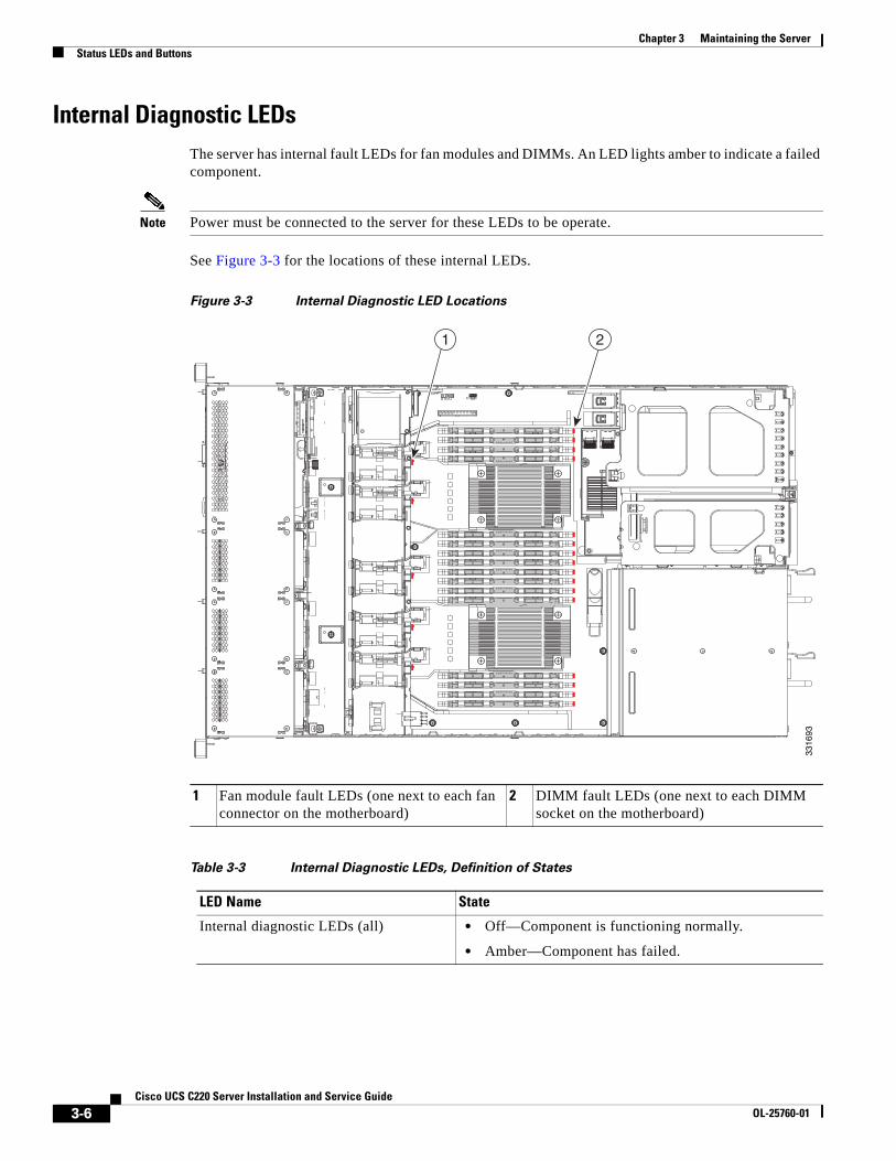
Internal Diagnostic LEDsThe server has internal fault LEDs for fan modules and DIMMs. An LED lights amber to indicate a failed component.
Note Power must be connected to the server for these LEDs to be operate.
See Figure 3-3 for the locations of these internal LEDs.
Figure 3-3 Internal Diagnostic LED Locations
1 Fan module fault LEDs (one next to each fan connector on the motherboard)
2 DIMM fault LEDs (one next to each DIMM socket on the motherboard)
Table 3-3 Internal Diagnostic LEDs, Definition of States
LED Name State
Internal diagnostic LEDs (all) • Off—Component is functioning normally.
• Amber—Component has failed.
FAN4
1 2
3316
93
3-7Cisco UCS C220 Server Installation and Service Guide
OL-25760-01
Chapter 3 Maintaining the ServerPreparing for Server Component Installation
Preparing for Server Component InstallationThis section describes how to prepare for component installation, and it includes the following topics:
• Required Equipment, page 3-7
• Shutting Down and Powering Off the Server, page 3-7
• Removing and Replacing the Server Top Cover, page 3-8
• Replaceable Component Locations, page 3-9
• Serial Number Location, page 3-10
• Color-Coded Touch Points, page 3-10
Required Equipment The following equipment is used to perform the procedures in this chapter:
• Number 2 Phillips-head screwdriver
• Electrostatic discharge (ESD) strap or other grounding equipment such as a grounded mat
Shutting Down and Powering Off the ServerThe server can run in two power modes:
• Main power mode—Power is supplied to all server components and any operating system on your drives can run.
• Standby power mode—Power is supplied only to the service processor and the cooling fans and it is safe to power off the server from this mode.
You can invoke a graceful shutdown or an hard shutdown by using either of the following methods:
• Use the CIMC management interface.
• Use the Power button on the server front panel. To use the Power button, follow these steps:
Step 1 Check the color of the Power Status LED (see the “Front Panel LEDs” section on page 3-2).
• Green—the server is in main power mode and must be shut down before it can be safely powered off. Go to Step 2.
• Amber—the server is already in standby mode and can be safely powered off. Go to Step 3.
Step 2 Invoke either a graceful shutdown or a hard shutdown:
Caution To avoid data loss or damage to your operating system, you should always invoke a graceful shutdown of the operating system.
• Graceful shutdown—Press and release the Power button. The operating system performs a graceful shutdown and the server goes to standby mode, which is indicated by an amber Power Status LED.
• Emergency shutdown—Press and hold the Power button for 4 seconds to force the main power off and immediately enter standby mode.
Step 3 Disconnect the power cords from the power supplies in your server to completely power off the server.
3-8Cisco UCS C220 Server Installation and Service Guide
OL-25760-01
Chapter 3 Maintaining the ServerPreparing for Server Component Installation
Removing and Replacing the Server Top Cover To remove or replace the top cover of the server, follow these steps:
Tip You do not have to remove the cover to replace hard drives or power supplies.
Step 1 Remove the top cover (see Figure 3-4):
a. Loosen the captive thumbscrew that secures the rear edge of the cover to the chassis.
b. Press the release button.
c. Using the rubber finger pads, push the top cover toward the server rear about one-half inch (1.27 cm), until it stops.
d. Lift the top cover straight up from the server and set it aside.
Step 2 Replace the top cover:
a. Place the cover on top of the server about one-half inch (1.27 cm) behind the lip of the chassis front cover panel. The cover should sit flat.
Note Make sure that the wrap-around flanged edge on the rear of the cover is correctly aligned with the chassis features so that there is clearance when sliding the cover forward.
b. Slide the top cover toward the front cover panel until it stops and the release button locks.
c. Tighten the captive thumbscrew that secures the rear edge of the cover to the chassis.
Figure 3-4 Removing the Top Cover
1 Front cover panel 3 Rubber finger pads (two)
2 Release button 4 Captive thumbscrew
4
1 2 3 3317
22
3-9Cisco UCS C220 Server Installation and Service Guide
OL-25760-01
Chapter 3 Maintaining the ServerPreparing for Server Component Installation
Replaceable Component Locations This section shows the locations of the components that are discussed in this chapter. The view in Figure 3-5 is from the top down with the top cover and air baffles removed.
Figure 3-5 Replaceable Component Locations
1 Drives (hot-swappable, accessed through front panel)
10 Trusted platform module socket on motherboard
2 Drive backplane 11 Standard-height PCIe riser (PCIe slot 1)
3 Mounting location on air baffle for LSI battery backup unit or SuperCap Power Module (air baffle not shown)
12 Half-height PCIe riser (PCIe slot 2)
4 Cooling fan modules (five) 13 Cisco Flexible Flash card slot SD2 socket on PCIe riser 2
5 SCU upgrade ROM header(PBG DYNAMIC SKU)
14 Cisco Flexible Flash card slot SD1 socket on PCIe riser 2
6 DIMM slots on motherboard (sixteen) 15 Internal USB 2.0 port
7 CPUs and heatsinks (two) 16 Power supplies (two)
8 Integrated RAID mini-SAS connectors on motherboard, SASPORT 1 and SASPORT 2
17 RTC battery on motherboard
9 Mezzanine RAID card,mini-SAS connectors SAS1 and SAS2
18 Software RAID 5 key header(SW RAID KEY)
FAN1FAN1FAN1
FAN2FAN2FAN2
FAN3FAN3FAN3
FAN4FAN4FAN4FAN4
FAN5FAN5FAN5
PSU2
PCIe1
PCIe2
PSU1
CPU1
CPU2
SAS1
SAS2
SA
S1
SA
S2
1718
15
11
10985 762 3 4
1
12
1314
16
3-10Cisco UCS C220 Server Installation and Service Guide
OL-25760-01
Chapter 3 Maintaining the ServerPreparing for Server Component Installation
Serial Number LocationThe serial number for the server is printed on a label on the top of the server, near the front.
Color-Coded Touch PointsThis server has color-coded touch points that indicate thumbscrews and latches on replaceable and hot-swappable components.
• Hot-swappable components have green plastic touch points. This includes the internal cooling fans and the power supplies. (An exception is the drive trays on the front panel, which are hot-swappable but not green).
• Some replaceable but non-hot-swappable components have light-blue plastic touch-points.
3-11Cisco UCS C220 Server Installation and Service Guide
OL-25760-01
Chapter 3 Maintaining the ServerInstalling or Replacing Server Components
Installing or Replacing Server Components
Warning Blank faceplates and cover panels serve three important functions: they prevent exposure to hazardous voltages and currents inside the chassis; they contain electromagnetic interference (EMI) that might disrupt other equipment; and they direct the flow of cooling air through the chassis. Do not operate the system unless all cards, faceplates, front covers, and rear covers are in place. Statement 1029
Warning Class 1 laser product.Statement 1008
Caution When handling server components, wear an ESD strap to avoid damage.
Tip You can press the Identification button on the front panel or rear panel to turn on a flashing Identification LED on the front and rear panels of the server. This allows you to locate the specific server that you are servicing when you go to the opposite side of the rack. You can also activate these LEDs remotely by using the CIMC interface. See the “Status LEDs and Buttons” section on page 3-2 for locations of these LEDs.
This section describes how to install and replace server components, and it includes the following topics:
• Replacing Hard Drives or Solid State Drives, page 3-12
• Replacing a Drive Backplane, page 3-14
• Replacing Fan Modules, page 3-16
• Replacing DIMMs, page 3-18
• Replacing CPUs and Heatsinks, page 3-23
• Replacing the Motherboard RTC Battery, page 3-30
• Replacing a Mezzanine Card, page 3-31
• Replacing a PCIe Riser, page 3-33
• Replacing a PCIe Card, page 3-35
• Replacing a Cisco Flexible Flash Card, page 3-40
• Replacing the LSI RAID Battery Backup Unit or SuperCap Power Module, page 3-45
• Installing a Trusted Platform Module, page 3-47
• Enabling the Intel Trusted Execution Technology (TXT) Feature For the TPM, page 3-48
• Replacing a SCU Upgrade ROM Module, page 3-50
• Replacing a Software RAID Key Module, page 3-51
• Replacing Power Supplies, page 3-52
• Enabling or Disabling the Internal USB Port, page 3-55
3-12Cisco UCS C220 Server Installation and Service Guide
OL-25760-01
Chapter 3 Maintaining the ServerInstalling or Replacing Server Components
Replacing Hard Drives or Solid State DrivesThis section includes the following information:
• Drive Population Guidelines, page 3-12
• Drive Replacement Procedure, page 3-13
Drive Population Guidelines
The server has two different drive backplane options:
• The Small Form Factor drives version can hold up to eight 2.5-inch hard drives or solid state drives.
• The Large Form Factor drives version can hold up to four 3.5-inch hard drives.
The drive-bay numbering is shown in Figure 3-6.
Figure 3-6 Drive Numbering, Small Form Factor
Figure 3-7 Drive Numbering, Large Form Factor
Observe these drive population guidelines for optimum performance:
• When populating drives, add drives to the lowest-numbered bays first.
• Keep an empty drive blanking tray in any unused bays to ensure proper air flow.
• You can mix hard drives and SSDs in the same server (the LFF version of the server does not support SSDs). However, You cannot configure a logical volume (virtual drive) that contains a mix of hard drives and SSDs. That is, when you create a logical volume, it must contain all hard drives or all SSDs.
HDD4 HDD5HDD1HDD6
HDD2HDD7
HDD3HDD8
3316
95
HDD1 HDD2 HDD3 HDD4
3316
96
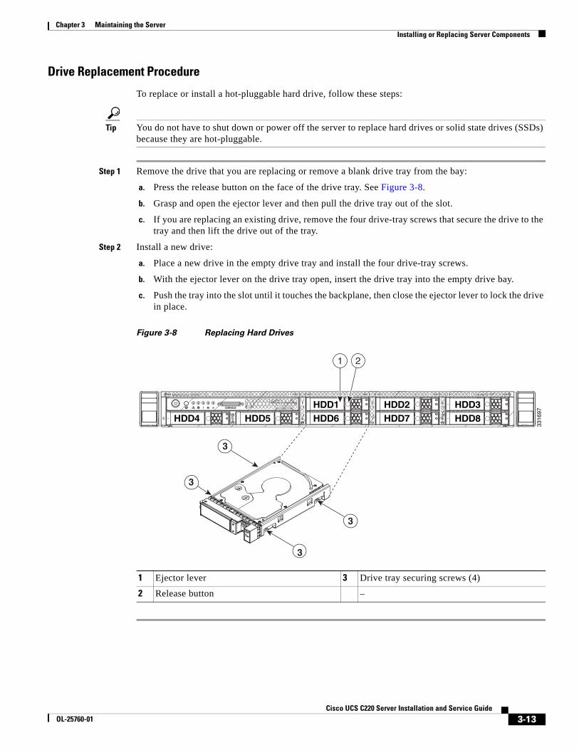
3-13Cisco UCS C220 Server Installation and Service Guide
OL-25760-01
Chapter 3 Maintaining the ServerInstalling or Replacing Server Components
Drive Replacement Procedure
To replace or install a hot-pluggable hard drive, follow these steps:
Tip You do not have to shut down or power off the server to replace hard drives or solid state drives (SSDs) because they are hot-pluggable.
Step 1 Remove the drive that you are replacing or remove a blank drive tray from the bay:
a. Press the release button on the face of the drive tray. See Figure 3-8.
b. Grasp and open the ejector lever and then pull the drive tray out of the slot.
c. If you are replacing an existing drive, remove the four drive-tray screws that secure the drive to the tray and then lift the drive out of the tray.
Step 2 Install a new drive:
a. Place a new drive in the empty drive tray and install the four drive-tray screws.
b. With the ejector lever on the drive tray open, insert the drive tray into the empty drive bay.
c. Push the tray into the slot until it touches the backplane, then close the ejector lever to lock the drive in place.
Figure 3-8 Replacing Hard Drives
1 Ejector lever 3 Drive tray securing screws (4)
2 Release button –
HDD4 HDD5HDD1HDD6
HDD2HDD7
HDD3HDD8
3
3
3
3
1 2
3316
97
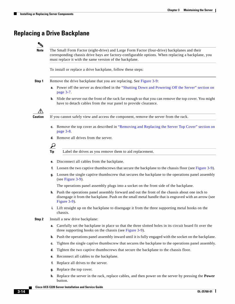
3-14Cisco UCS C220 Server Installation and Service Guide
OL-25760-01
Chapter 3 Maintaining the ServerInstalling or Replacing Server Components
Replacing a Drive Backplane
Note The Small Form Factor (eight-drive) and Large Form Factor (four-drive) backplanes and their corresponding chassis drive bays are factory-configurable options. When replacing a backplane, you must replace it with the same version of the backplane.
To install or replace a drive backplane, follow these steps:
Step 1 Remove the drive backplane that you are replacing. See Figure 3-9:
a. Power off the server as described in the “Shutting Down and Powering Off the Server” section on page 3-7.
b. Slide the server out the front of the rack far enough so that you can remove the top cover. You might have to detach cables from the rear panel to provide clearance.
Caution If you cannot safely view and access the component, remove the server from the rack.
c. Remove the top cover as described in “Removing and Replacing the Server Top Cover” section on page 3-8.
d. Remove all drives from the server.
Tip Label the drives as you remove them to aid replacement.
e. Disconnect all cables from the backplane.
f. Loosen the two captive thumbscrews that secure the backplane to the chassis floor (see Figure 3-9).
g. Loosen the single captive thumbscrew that secures the backplane to the operations panel assembly (see Figure 3-9).
The operations panel assembly plugs into a socket on the front side of the backplane.
h. Push the operations panel assembly forward and out the front of the chassis about one inch to disengage it from the backplane. Push on the small metal handle that is engraved with an arrow (see Figure 3-9).
i. Lift straight up on the backplane to disengage it from the three supporting metal hooks on the chassis.
Step 2 Install a new drive backplane:
a. Carefully set the backplane in place so that the three slotted holes in its circuit board fit over the three supporting hooks on the chassis (see Figure 3-9).
b. Push the operations panel assembly inward until it is fully engaged with the socket on the backplane.
c. Tighten the single captive thumbscrew that secures the backplane to the operations panel assembly.
d. Tighten the two captive thumbscrews that secure the backplane to the chassis floor.
e. Reconnect all cables to the backplane.
f. Replace all drives to the server.
g. Replace the top cover.
h. Replace the server in the rack, replace cables, and then power on the server by pressing the Power button.
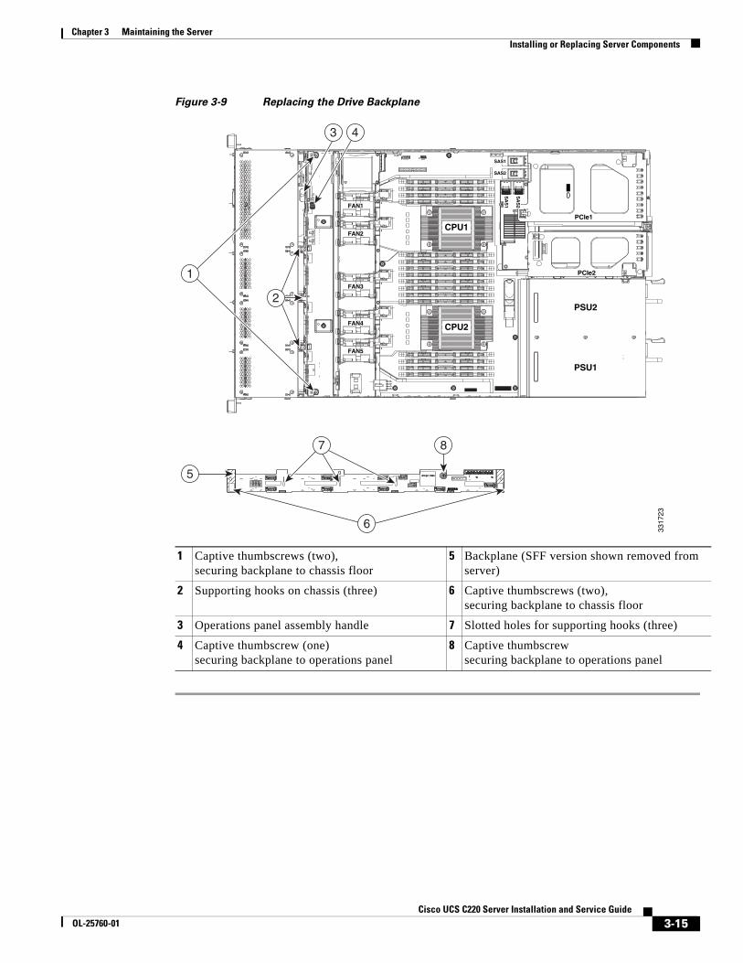
3-15Cisco UCS C220 Server Installation and Service Guide
OL-25760-01
Chapter 3 Maintaining the ServerInstalling or Replacing Server Components
Figure 3-9 Replacing the Drive Backplane
1 Captive thumbscrews (two),securing backplane to chassis floor
5 Backplane (SFF version shown removed from server)
2 Supporting hooks on chassis (three) 6 Captive thumbscrews (two),securing backplane to chassis floor
3 Operations panel assembly handle 7 Slotted holes for supporting hooks (three)
4 Captive thumbscrew (one)securing backplane to operations panel
8 Captive thumbscrewsecuring backplane to operations panel
FAN1FAN1FAN1
FAN2FAN2FAN2
FAN3FAN3FAN3
FAN4FAN4FAN4FAN4
FAN5FAN5FAN5
PSU2
PCIe1
PCIe2
PSU1
CPU1
CPU2
SAS1
SAS2
SA
S1
SA
S2
87
5
3 4
1
2
6
3317
23
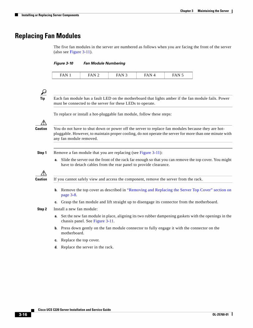
3-16Cisco UCS C220 Server Installation and Service Guide
OL-25760-01
Chapter 3 Maintaining the ServerInstalling or Replacing Server Components
Replacing Fan Modules The five fan modules in the server are numbered as follows when you are facing the front of the server (also see Figure 3-11).
Figure 3-10 Fan Module Numbering
Tip Each fan module has a fault LED on the motherboard that lights amber if the fan module fails. Power must be connected to the server for these LEDs to operate.
To replace or install a hot-pluggable fan module, follow these steps:
Caution You do not have to shut down or power off the server to replace fan modules because they are hot- pluggable. However, to maintain proper cooling, do not operate the server for more than one minute with any fan module removed.
Step 1 Remove a fan module that you are replacing (see Figure 3-11):
a. Slide the server out the front of the rack far enough so that you can remove the top cover. You might have to detach cables from the rear panel to provide clearance.
Caution If you cannot safely view and access the component, remove the server from the rack.
b. Remove the top cover as described in “Removing and Replacing the Server Top Cover” section on page 3-8.
c. Grasp the fan module and lift straight up to disengage its connector from the motherboard.
Step 2 Install a new fan module:
a. Set the new fan module in place, aligning its two rubber dampening gaskets with the openings in the chassis panel. See Figure 3-11.
b. Press down gently on the fan module connector to fully engage it with the connector on the motherboard.
c. Replace the top cover.
d. Replace the server in the rack.
FAN 1 FAN 2 FAN 3 FAN 4 FAN 5
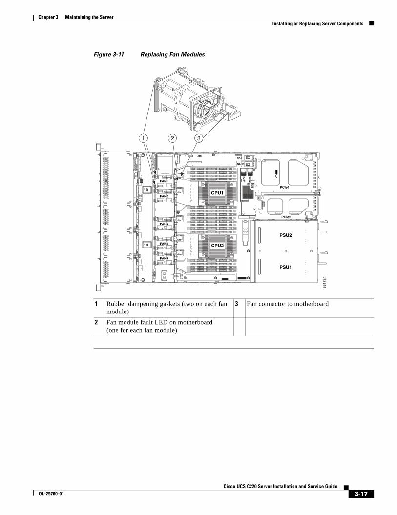
3-17Cisco UCS C220 Server Installation and Service Guide
OL-25760-01
Chapter 3 Maintaining the ServerInstalling or Replacing Server Components
Figure 3-11 Replacing Fan Modules
1 Rubber dampening gaskets (two on each fan module)
3 Fan connector to motherboard
2 Fan module fault LED on motherboard(one for each fan module)
FAN1FAN1FAN1
FAN2FAN2FAN2
FAN3FAN3FAN3
FAN4FAN4FAN4FAN4
FAN5FAN5FAN5
PSU2
PCIe1
PCIe2
PSU1
CPU1
CPU2
SAS1
SAS2
SA
S1
SA
S2
1 2 3
3317
24
3-18Cisco UCS C220 Server Installation and Service Guide
OL-25760-01
Chapter 3 Maintaining the ServerInstalling or Replacing Server Components
Replacing DIMMs This section includes the following topics:
• Memory Performance Guidelines and Population Rules, page 3-18
• DIMM Replacement Procedure, page 3-21
Caution DIMMs and their sockets are fragile and must be handled with care to avoid damage during installation.
Caution Cisco does not support 3rd-party DIMMs. Using non-Cisco DIMMs in the server might result in system problems or damage to the motherboard.
Note To ensure the best server performance, it is important that you are familiar with memory performance guidelines and population rules before you install or replace memory.
Memory Performance Guidelines and Population Rules
This section describes the type of memory that the server requires and its effect on performance. The section includes the following topics:
• DIMM Slot Numbering, page 3-18
• DIMM Population Rules, page 3-19
• Memory Mirroring, page 3-21
DIMM Slot Numbering
Figure 3-12 shows the numbering of the DIMM slots.
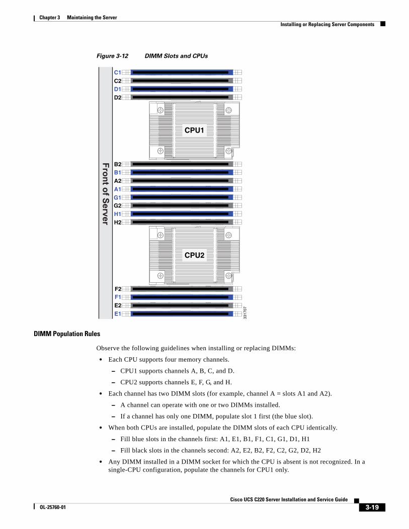
3-19Cisco UCS C220 Server Installation and Service Guide
OL-25760-01
Chapter 3 Maintaining the ServerInstalling or Replacing Server Components
Figure 3-12 DIMM Slots and CPUs
DIMM Population Rules
Observe the following guidelines when installing or replacing DIMMs:
• Each CPU supports four memory channels.
– CPU1 supports channels A, B, C, and D.
– CPU2 supports channels E, F, G, and H.
• Each channel has two DIMM slots (for example, channel A = slots A1 and A2).
– A channel can operate with one or two DIMMs installed.
– If a channel has only one DIMM, populate slot 1 first (the blue slot).
• When both CPUs are installed, populate the DIMM slots of each CPU identically.
– Fill blue slots in the channels first: A1, E1, B1, F1, C1, G1, D1, H1
– Fill black slots in the channels second: A2, E2, B2, F2, C2, G2, D2, H2
• Any DIMM installed in a DIMM socket for which the CPU is absent is not recognized. In a single-CPU configuration, populate the channels for CPU1 only.
C1
C2D1D2
B2B1A2A1G1G2
H2H1
F2F1
E1E2
Front of Server
CPU1
CPU2
3317
07
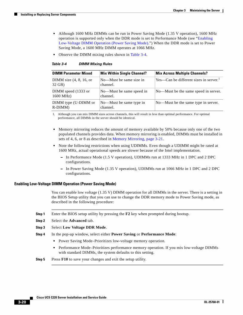
3-20Cisco UCS C220 Server Installation and Service Guide
OL-25760-01
Chapter 3 Maintaining the ServerInstalling or Replacing Server Components
• Although 1600 MHz DIMMs can be run in Power Saving Mode (1.35 V operation), 1600 MHz operation is supported only when the DDR mode is set to Performance Mode (see “Enabling Low-Voltage DIMM Operation (Power Saving Mode).”) When the DDR mode is set to Power Saving Mode, a 1600 MHz DIMM operates at 1066 MHz.
• Observe the DIMM mixing rules shown in Table 3-4.
• Memory mirroring reduces the amount of memory available by 50% because only one of the two populated channels provides data. When memory mirroring is enabled, DIMMs must be installed in sets of 4, 6, or 8 as described in Memory Mirroring, page 3-21.
• Note the following restrictions when using UDIMMs. Even though a UDIMM might be rated at 1600 MHz, actual operational speeds are slower because of the Intel implementation.
– In Performance Mode (1.5 V operation), UDIMMs run at 1333 MHz in 1 DPC and 2 DPC configurations.
– In Power Saving Mode (1.35 V operation), UDIMMs run at 1066 MHz in 1 DPC and 2 DPC configurations.
Enabling Low-Voltage DIMM Operation (Power Saving Mode)
You can enable low voltage (1.35 V) DIMM operation for all DIMMs in the server. There is a setting in the BIOS Setup utility that you can use to change the DDR memory mode to Power Saving mode, as described in the following procedure:
Step 1 Enter the BIOS setup utility by pressing the F2 key when prompted during bootup.
Step 2 Select the Advanced tab.
Step 3 Select Low Voltage DDR Mode.
Step 4 In the pop-up window, select either Power Saving or Performance Mode:
• Power Saving Mode–Prioritizes low-voltage memory operation.
• Performance Mode–Prioritizes performance memory operation. If you mix low-voltage DIMMs with standard DIMMs, the system defaults to this setting.
Step 5 Press F10 to save your changes and exit the setup utility.
Table 3-4 DIMM Mixing Rules
DIMM Parameter Mixed Mix Within Single Channel? Mix Across Multiple Channels?
DIMM size (4, 8, 16, or 32 GB)
No—Must be same size in channel.
Yes—Can be different sizes in server.1
1. Although you can mix DIMM sizes across channels, this will result in less than optimal performance. For optimal performance, all DIMMs in the server should be identical.
DIMM speed (1333 or 1600 MHz)
No—Must be same speed in channel.
No—Must be the same speed in server.
DIMM type (U-DIMM or R-DIMM)
No—Must be same type in channel.
No—Must be the same type in server.
3-21Cisco UCS C220 Server Installation and Service Guide
OL-25760-01
Chapter 3 Maintaining the ServerInstalling or Replacing Server Components
Memory Mirroring
When memory mirroring is enabled, the memory subsystem simultaneously writes identical data to two channels. If a memory read from one of the channels returns incorrect data due to an uncorrectable memory error, the system automatically retrieves the data from the other channel. A transient or soft error in one channel does not affect the mirrored data, and operation continues unless there is a simultaneous error in exactly the same location on a DIMM and its mirrored DIMM. Memory mirroring reduces the amount of memory available to the operating system by 50% because only one of the two populated channels provides data.
Note You must choose to enable memory mirroring in the server BIOS setup utility, under Advanced > Memory Configuration > Mirroring.
If you choose to enable memory mirroring, populate the DIMM slots in the order shown in Table 3-5.
DIMM Replacement Procedure
This section includes the following topics:
• Identifying a Faulty DIMM, page 3-21
• Replacing DIMMs, page 3-21
Identifying a Faulty DIMM
Each DIMM slot has a corresponding DIMM fault LED. See Figure 3-3 for the locations of these LEDs.
The LEDs light amber to indicate a faulty DIMM. Power must be present in the server for these LEDs to operate.
Replacing DIMMs
To install a DIMM assembly, follow these steps:
Step 1 Remove the DIMM that you are replacing:
a. Power off the server as described in the “Shutting Down and Powering Off the Server” section on page 3-7.
b. Slide the server out the front of the rack far enough so that you can remove the top cover. You might have to detach cables from the rear panel to provide clearance.
Caution If you cannot safely view and access the component, remove the server from the rack.
Table 3-5 Memory Mirroring DIMM Population
Number of DIMMs per CPU CPU 1 Population CPU2 Population
4 A1, B1; A2, B2 E1, F1; E2, F2
6 A1, B1; C1, D1; A2; B2 E1, F1; G1, H1; E2, F2
8 A1, B1; C1, D1; A2, B2; C2, D2 E1, F1; G1, H1; E2, F2; G2, H2
3-22Cisco UCS C220 Server Installation and Service Guide
OL-25760-01
Chapter 3 Maintaining the ServerInstalling or Replacing Server Components
c. Remove the top cover as described in “Removing and Replacing the Server Top Cover” section on page 3-8.
d. Identify the faulty DIMM by observing the DIMM slot fault LEDs on the motherboard.
e. Open the ejector levers at both ends of the DIMM slot, then lift the DIMM out of the slot.
Step 2 Install a new DIMM:
Note Before installing DIMMs, refer to the population guidelines. See Memory Performance Guidelines and Population Rules, page 3-18.
f. Align the new DIMM with the empty slot on the motherboard. Use the alignment key in the DIMM slot to correctly orient the DIMM.
g. Push down evenly on the top corners of the DIMM until it is fully seated and the ejector levers on both ends lock into place.
h. Replace the top cover.
i. Replace the server in the rack, replace cables, and then power on the server by pressing the Power button.
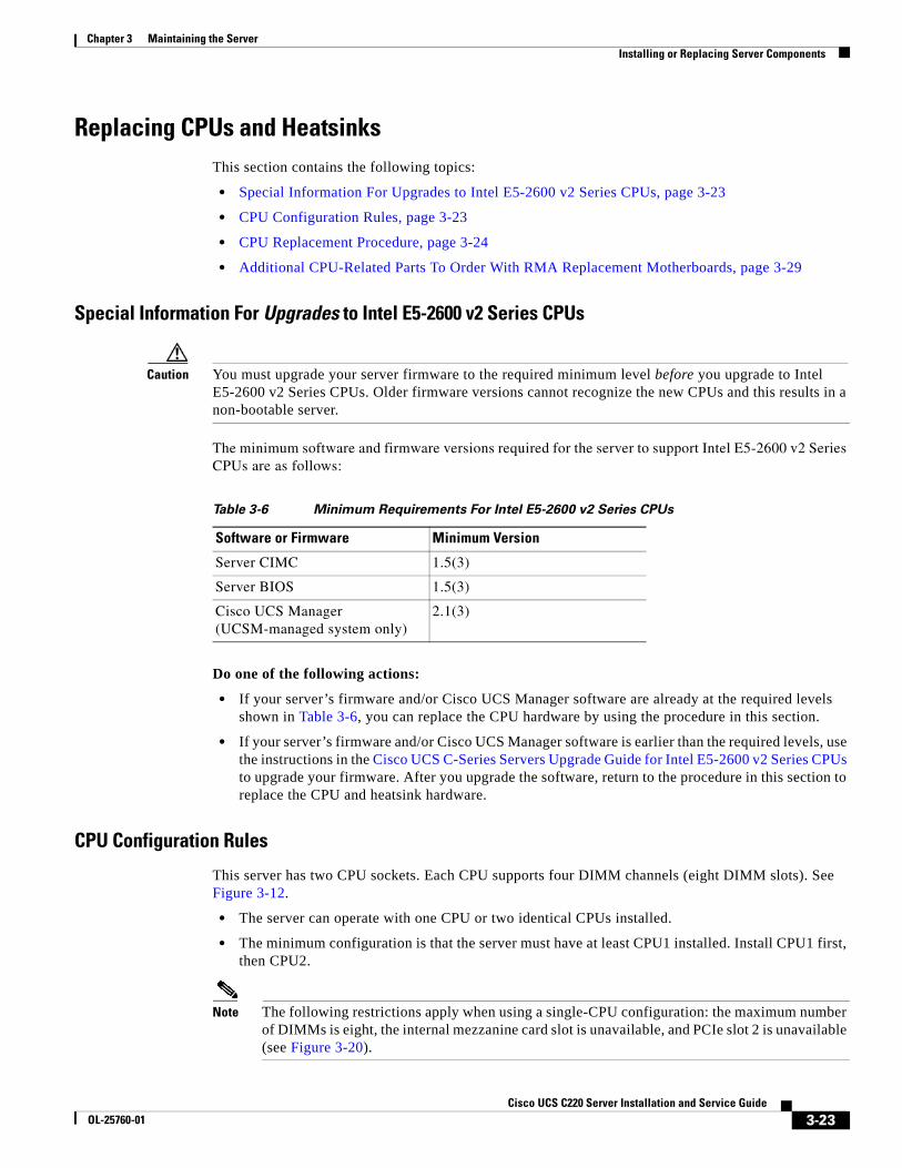
3-23Cisco UCS C220 Server Installation and Service Guide
OL-25760-01
Chapter 3 Maintaining the ServerInstalling or Replacing Server Components
Replacing CPUs and Heatsinks This section contains the following topics:
• Special Information For Upgrades to Intel E5-2600 v2 Series CPUs, page 3-23
• CPU Configuration Rules, page 3-23
• CPU Replacement Procedure, page 3-24
• Additional CPU-Related Parts To Order With RMA Replacement Motherboards, page 3-29
Special Information For Upgrades to Intel E5-2600 v2 Series CPUs
Caution You must upgrade your server firmware to the required minimum level before you upgrade to Intel E5-2600 v2 Series CPUs. Older firmware versions cannot recognize the new CPUs and this results in a non-bootable server.
The minimum software and firmware versions required for the server to support Intel E5-2600 v2 Series CPUs are as follows:
Do one of the following actions:
• If your server’s firmware and/or Cisco UCS Manager software are already at the required levels shown in Table 3-6, you can replace the CPU hardware by using the procedure in this section.
• If your server’s firmware and/or Cisco UCS Manager software is earlier than the required levels, use the instructions in the Cisco UCS C-Series Servers Upgrade Guide for Intel E5-2600 v2 Series CPUs to upgrade your firmware. After you upgrade the software, return to the procedure in this section to replace the CPU and heatsink hardware.
CPU Configuration Rules
This server has two CPU sockets. Each CPU supports four DIMM channels (eight DIMM slots). See Figure 3-12.
• The server can operate with one CPU or two identical CPUs installed.
• The minimum configuration is that the server must have at least CPU1 installed. Install CPU1 first, then CPU2.
Note The following restrictions apply when using a single-CPU configuration: the maximum number of DIMMs is eight, the internal mezzanine card slot is unavailable, and PCIe slot 2 is unavailable (see Figure 3-20).
Table 3-6 Minimum Requirements For Intel E5-2600 v2 Series CPUs
Software or Firmware Minimum Version
Server CIMC 1.5(3)
Server BIOS 1.5(3)
Cisco UCS Manager (UCSM-managed system only)
2.1(3)
3-24Cisco UCS C220 Server Installation and Service Guide
OL-25760-01
Chapter 3 Maintaining the ServerInstalling or Replacing Server Components
CPU Replacement Procedure
Caution CPUs and their motherboard sockets are fragile and must be handled with care to avoid damaging pins during installation. The CPUs must be installed with heatsinks and their thermal pads to ensure proper cooling. Failure to install a CPU correctly might result in damage to the server.
Caution The Pick-and-Place tools used in this procedure are required to prevent damage to the contact pins between the motherboard and the CPU. Do not attempt this procedure without the required tools, which are included with each CPU option kit. If you do not have the tool, you can order a spare: Cisco PID UCS-CPU-EP-PNP= for 10-, 8-, 6-, 4-, or 2-core CPUs (green); UCS-CPU-EP2-PNP= for v2 12-core CPUs (purple).
To install or replace a CPU heatsink and CPU, follow these steps:
Step 1 Remove the CPU and heatsink that you are replacing:
a. Power off the server as described in the “Shutting Down and Powering Off the Server” section on page 3-7.
b. Slide the server out the front of the rack far enough so that you can remove the top cover. You might have to detach cables from the rear panel to provide clearance.
Caution If you cannot safely view and access the component, remove the server from the rack.
c. Remove the top cover as described in “Removing and Replacing the Server Top Cover” section on page 3-8.
d. Use a Number 2 Phillips-head screwdriver to loosen the four captive screws that secure the heatsink and then lift it off of the CPU.
Note Alternate loosening each screw evenly to avoid damaging the heatsink or CPU.
e. Unclip the first CPU retaining latch labelled with the icon, then unclip the second retaining latch labelled with the icon. See Figure 3-13.
f. Open the hinged CPU cover plate.
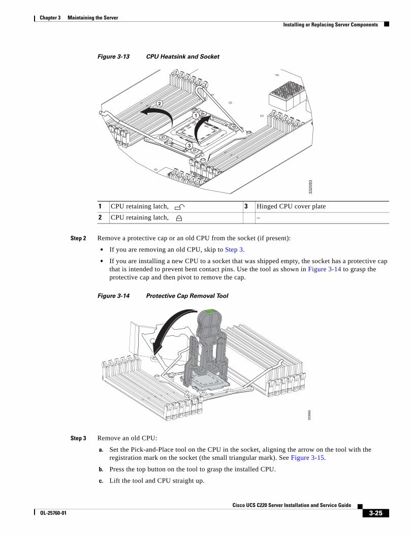
3-25Cisco UCS C220 Server Installation and Service Guide
OL-25760-01
Chapter 3 Maintaining the ServerInstalling or Replacing Server Components
Figure 3-13 CPU Heatsink and Socket
Step 2 Remove a protective cap or an old CPU from the socket (if present):
• If you are removing an old CPU, skip to Step 3.
• If you are installing a new CPU to a socket that was shipped empty, the socket has a protective cap that is intended to prevent bent contact pins. Use the tool as shown in Figure 3-14 to grasp the protective cap and then pivot to remove the cap.
Figure 3-14 Protective Cap Removal Tool
Step 3 Remove an old CPU:
a. Set the Pick-and-Place tool on the CPU in the socket, aligning the arrow on the tool with the registration mark on the socket (the small triangular mark). See Figure 3-15.
b. Press the top button on the tool to grasp the installed CPU.
c. Lift the tool and CPU straight up.
1 CPU retaining latch, 3 Hinged CPU cover plate
2 CPU retaining latch, –
1
3
2
3320
9333
3565
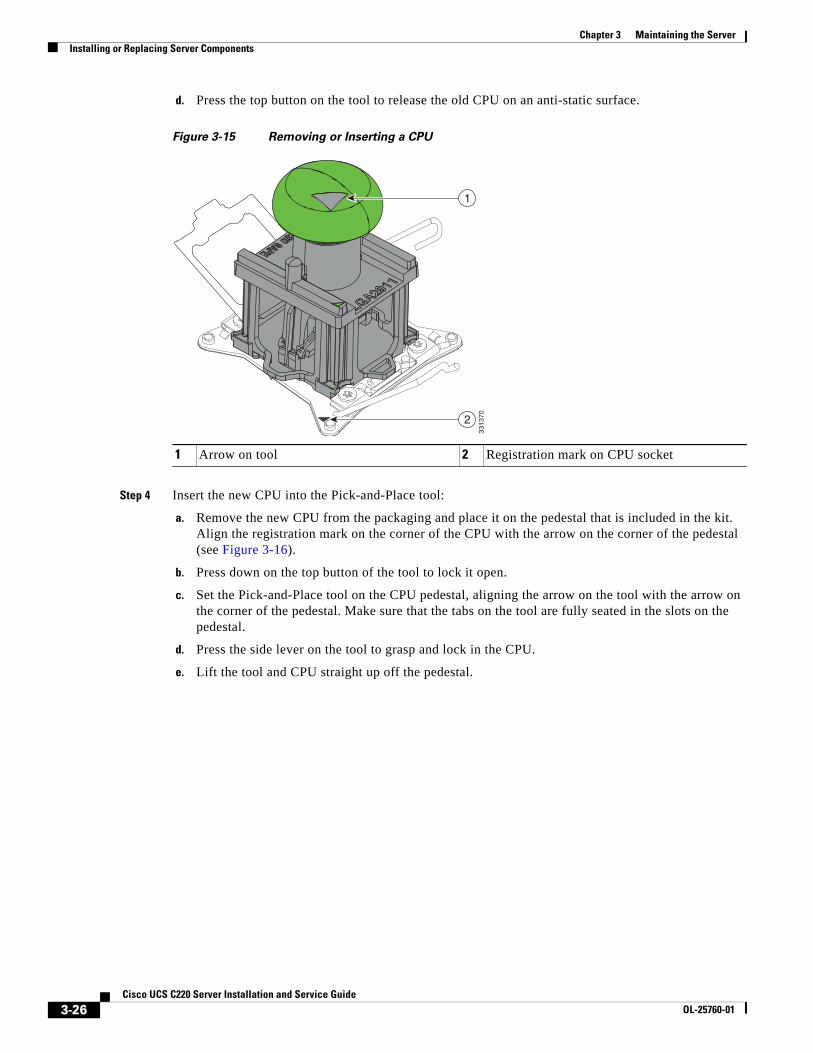
3-26Cisco UCS C220 Server Installation and Service Guide
OL-25760-01
Chapter 3 Maintaining the ServerInstalling or Replacing Server Components
d. Press the top button on the tool to release the old CPU on an anti-static surface.
Figure 3-15 Removing or Inserting a CPU
Step 4 Insert the new CPU into the Pick-and-Place tool:
a. Remove the new CPU from the packaging and place it on the pedestal that is included in the kit. Align the registration mark on the corner of the CPU with the arrow on the corner of the pedestal (see Figure 3-16).
b. Press down on the top button of the tool to lock it open.
c. Set the Pick-and-Place tool on the CPU pedestal, aligning the arrow on the tool with the arrow on the corner of the pedestal. Make sure that the tabs on the tool are fully seated in the slots on the pedestal.
d. Press the side lever on the tool to grasp and lock in the CPU.
e. Lift the tool and CPU straight up off the pedestal.
1 Arrow on tool 2 Registration mark on CPU socket
3313
70
1
2

3-27Cisco UCS C220 Server Installation and Service Guide
OL-25760-01
Chapter 3 Maintaining the ServerInstalling or Replacing Server Components
Figure 3-16 CPU and Pick-and-Place Tool on Pedestal
Step 5 Install a new CPU:
a. Set the Pick-and-Place tool with CPU over the empty CPU socket on the motherboard.
Note Align the arrow on the top of the tool with the registration mark (small triangle) that is stamped on the metal of the CPU socket, as shown in Figure 3-15.
b. Press the top button on the tool to set the CPU into the socket. Remove the empty tool.
c. Close the hinged CPU cover plate.
d. Clip down the CPU retaining latch with the icon, then clip down the CPU retaining latch with the icon. See Figure 3-13.
Step 6 Install a heatsink:
Caution The heatsink must have a new, undamaged thermal pad on the heatsink-to-CPU surface to ensure proper cooling. If you are replacing a heatsink that was previously used, you must remove the old thermal pad. If you are installing a new heatsink, skip to step d. below.
a. Apply an alcohol-based cleaning solution to the old thermal pad and let it soak for a least 15 seconds.
b. Wipe all of the old thermal pad off the old heatsink using a soft cloth that will not scratch the heatsink surface.
1 Arrow marks for alignment –
1
1
1
3335
66
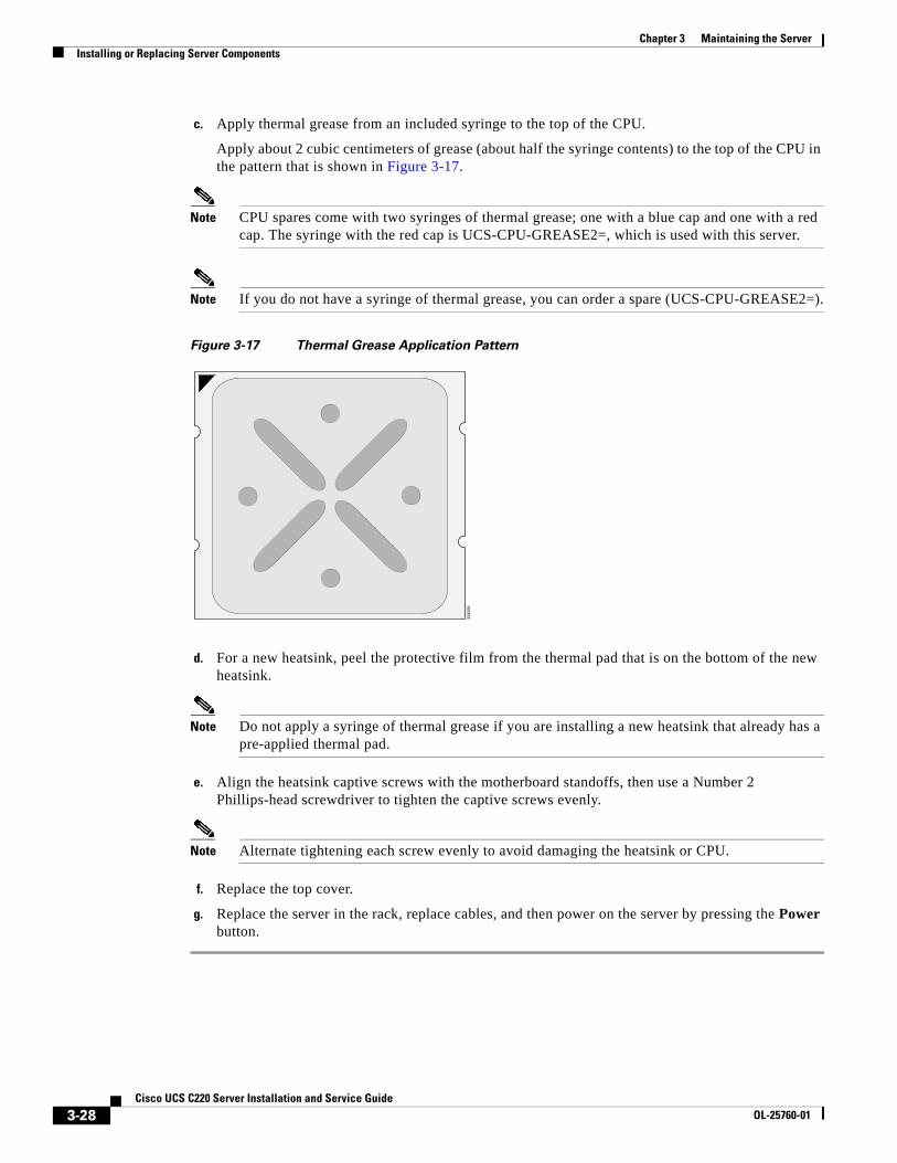
3-28Cisco UCS C220 Server Installation and Service Guide
OL-25760-01
Chapter 3 Maintaining the ServerInstalling or Replacing Server Components
c. Apply thermal grease from an included syringe to the top of the CPU.
Apply about 2 cubic centimeters of grease (about half the syringe contents) to the top of the CPU in the pattern that is shown in Figure 3-17.
Note CPU spares come with two syringes of thermal grease; one with a blue cap and one with a red cap. The syringe with the red cap is UCS-CPU-GREASE2=, which is used with this server.
Note If you do not have a syringe of thermal grease, you can order a spare (UCS-CPU-GREASE2=).
Figure 3-17 Thermal Grease Application Pattern
d. For a new heatsink, peel the protective film from the thermal pad that is on the bottom of the new heatsink.
Note Do not apply a syringe of thermal grease if you are installing a new heatsink that already has a pre-applied thermal pad.
e. Align the heatsink captive screws with the motherboard standoffs, then use a Number 2 Phillips-head screwdriver to tighten the captive screws evenly.
Note Alternate tightening each screw evenly to avoid damaging the heatsink or CPU.
f. Replace the top cover.
g. Replace the server in the rack, replace cables, and then power on the server by pressing the Power button.
3342
95
3-29Cisco UCS C220 Server Installation and Service Guide
OL-25760-01
Chapter 3 Maintaining the ServerInstalling or Replacing Server Components
Additional CPU-Related Parts To Order With RMA Replacement Motherboards
When a return material authorization (RMA) of the motherboard or CPU is done on a Cisco UCS C-series server, there are additional parts that might not be included with the CPU or motherboard spare bill of materials (BOM). The TAC engineer might need to add the additional parts to the RMA to help ensure a successful replacement.
• Scenario 1—You are re-using the existing heatsinks:
– Heat sink cleaning kit (UCSX-HSCK=)
– Thermal grease kit for C220 (UCS-CPU-GREASE2=)
– Intel CPU Pick-n-Place tool: UCS-CPU-EP-PNP= for 10-, 8-, 6-, 4-, or 2-core CPUs (green); or UCS-CPU-EP2-PNP= for v2 12-core CPUs (purple)
• Scenario 2—You are replacing the existing heatsinks:
– Heat sink (UCSC-HS-C220M3=)
– Heat sink cleaning kit (UCSX-HSCK=)
– Intel CPU Pick-n-Place tool: UCS-CPU-EP-PNP= for 10-, 8-, 6-, 4-, or 2-core CPUs (green); or UCS-CPU-EP2-PNP= for v2 12-core CPUs (purple)
A CPU heatsink cleaning kit is good for up to four CPU and heatsink cleanings. The cleaning kit contains two bottles of solution, one to clean the CPU and heatsink of old thermal interface material and the other to prepare the surface of the heatsink.
New heatsink spares have preinstalled thermal interface material covered by a small sheet of plastic. It is important to clean the old thermal interface material off of the CPU prior to installing the heatsinks. Therefore, when ordering new heatsinks it is still necessary to order the heatsink cleaning kit at a minimum.
3-30Cisco UCS C220 Server Installation and Service Guide
OL-25760-01
Chapter 3 Maintaining the ServerInstalling or Replacing Server Components
Replacing the Motherboard RTC Battery
Warning There is danger of explosion if the battery is replaced incorrectly. Replace the battery only with the same or equivalent type recommended by the manufacturer. Dispose of used batteries according to the manufacturer’s instructions. [Statement 1015]
The real-time clock (RTC) battery retains system settings when the server is disconnected from power. The battery type is Panasonic CR2032 or equivalent.
To replace or install the motherboard CMOS battery, follow these steps:
Step 1 Remove the RTC battery (see Figure 3-18):
a. Power off the server as described in the “Shutting Down and Powering Off the Server” section on page 3-7.
b. Slide the server out the front of the rack far enough so that you can remove the top cover. You might have to detach cables from the rear panel to provide clearance.
Caution If you cannot safely view and access the component, remove the server from the rack.
c. Remove the top cover as described in “Removing and Replacing the Server Top Cover” section on page 3-8.
d. Locate the RTC battery. See Figure 3-18.
e. Gently remove the battery from the holder on the motherboard.
Step 2 Install an RTC battery:
a. Gently insert the battery into the holder and inside the retaining clip.
Note The positive side of the battery marked “3V+” should face the retaining clip and chassis wall.
b. Push the battery into the socket until it is fully seated.
c. Replace the top cover.
d. Replace the server in the rack, replace cables, and power on the server by pressing the Power button.
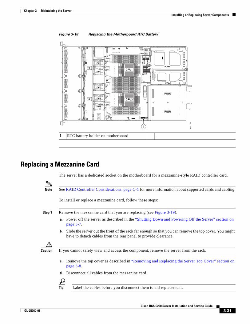
3-31Cisco UCS C220 Server Installation and Service Guide
OL-25760-01
Chapter 3 Maintaining the ServerInstalling or Replacing Server Components
Figure 3-18 Replacing the Motherboard RTC Battery
Replacing a Mezzanine CardThe server has a dedicated socket on the motherboard for a mezzanine-style RAID controller card.
Note See RAID Controller Considerations, page C-1 for more information about supported cards and cabling.
To install or replace a mezzanine card, follow these steps:
Step 1 Remove the mezzanine card that you are replacing (see Figure 3-19):
a. Power off the server as described in the “Shutting Down and Powering Off the Server” section on page 3-7.
b. Slide the server out the front of the rack far enough so that you can remove the top cover. You might have to detach cables from the rear panel to provide clearance.
Caution If you cannot safely view and access the component, remove the server from the rack.
c. Remove the top cover as described in “Removing and Replacing the Server Top Cover” section on page 3-8.
d. Disconnect all cables from the mezzanine card.
Tip Label the cables before you disconnect them to aid replacement.
1 RTC battery holder on motherboard –
FAN1FAN1FAN1
FAN2FAN2FAN2
FAN3FAN3FAN3
FAN4FAN4FAN4FAN4
FAN5FAN5FAN5
PSU2
PCIe1
PCIe2
PSU1
CPU1
CPU2
SAS1
SAS2
SA
S1
SA
S2
1
3317
10
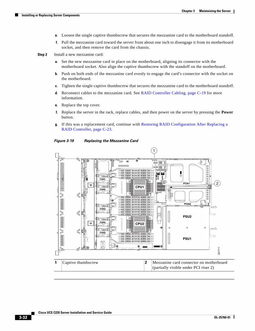
3-32Cisco UCS C220 Server Installation and Service Guide
OL-25760-01
Chapter 3 Maintaining the ServerInstalling or Replacing Server Components
e. Loosen the single captive thumbscrew that secures the mezzanine card to the motherboard standoff.
f. Pull the mezzanine card toward the server front about one inch to disengage it from its motherboard socket, and then remove the card from the chassis.
Step 2 Install a new mezzanine card:
a. Set the new mezzanine card in place on the motherboard, aligning its connector with the motherboard socket. Also align the captive thumbscrew with the standoff on the motherboard.
b. Push on both ends of the mezzanine card evenly to engage the card’s connector with the socket on the motherboard.
c. Tighten the single captive thumbscrew that secures the mezzanine card to the motherboard standoff.
d. Reconnect cables to the mezzanine card. See RAID Controller Cabling, page C-19 for more information.
e. Replace the top cover.
f. Replace the server in the rack, replace cables, and then power on the server by pressing the Power button.
g. If this was a replacement card, continue with Restoring RAID Configuration After Replacing a RAID Controller, page C-23.
Figure 3-19 Replacing the Mezzanine Card
1 Captive thumbscrew 2 Mezzanine card connector on motherboard(partially visible under PCI riser 2)
FAN1FAN1FAN1
FAN2FAN2FAN2
FAN3FAN3FAN3
FAN4FAN4FAN4FAN4
FAN5FAN5FAN5
PSU2
PCIe1
PCIe2
PSU1
CPU1
CPU2
SAS1
SAS2
SA
S1
SA
S2
2
1
3317
11
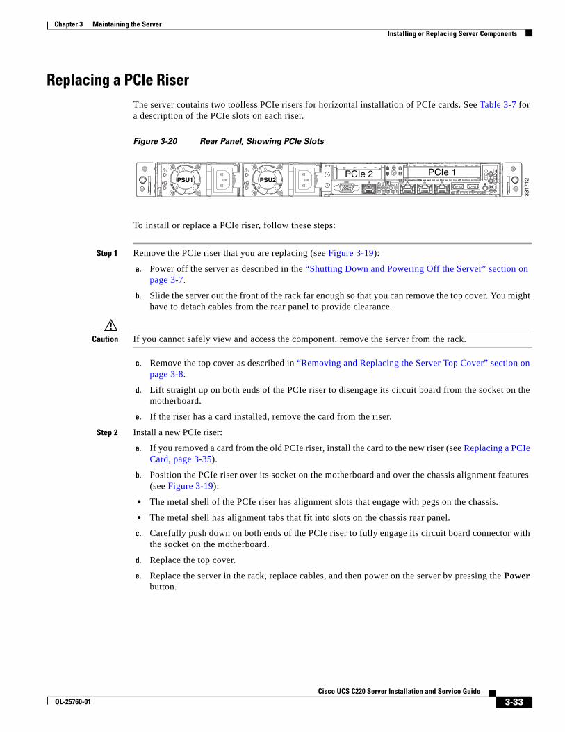
3-33Cisco UCS C220 Server Installation and Service Guide
OL-25760-01
Chapter 3 Maintaining the ServerInstalling or Replacing Server Components
Replacing a PCIe Riser The server contains two toolless PCIe risers for horizontal installation of PCIe cards. See Table 3-7 for a description of the PCIe slots on each riser.
Figure 3-20 Rear Panel, Showing PCIe Slots
To install or replace a PCIe riser, follow these steps:
Step 1 Remove the PCIe riser that you are replacing (see Figure 3-19):
a. Power off the server as described in the “Shutting Down and Powering Off the Server” section on page 3-7.
b. Slide the server out the front of the rack far enough so that you can remove the top cover. You might have to detach cables from the rear panel to provide clearance.
Caution If you cannot safely view and access the component, remove the server from the rack.
c. Remove the top cover as described in “Removing and Replacing the Server Top Cover” section on page 3-8.
d. Lift straight up on both ends of the PCIe riser to disengage its circuit board from the socket on the motherboard.
e. If the riser has a card installed, remove the card from the riser.
Step 2 Install a new PCIe riser:
a. If you removed a card from the old PCIe riser, install the card to the new riser (see Replacing a PCIe Card, page 3-35).
b. Position the PCIe riser over its socket on the motherboard and over the chassis alignment features (see Figure 3-19):
• The metal shell of the PCIe riser has alignment slots that engage with pegs on the chassis.
• The metal shell has alignment tabs that fit into slots on the chassis rear panel.
c. Carefully push down on both ends of the PCIe riser to fully engage its circuit board connector with the socket on the motherboard.
d. Replace the top cover.
e. Replace the server in the rack, replace cables, and then power on the server by pressing the Power button.
PSU1PSU1 PSU2PSU2PSU1 PSU2
3317
12
PCIe 2 PCIe 1
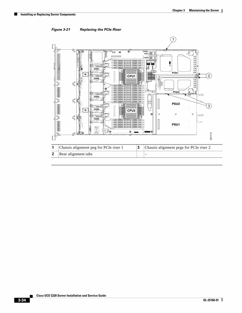
3-34Cisco UCS C220 Server Installation and Service Guide
OL-25760-01
Chapter 3 Maintaining the ServerInstalling or Replacing Server Components
Figure 3-21 Replacing the PCIe Riser
1 Chassis alignment peg for PCIe riser 1 3 Chassis alignment pegs for PCIe riser 2
2 Rear alignment tabs –
FAN1FAN1FAN1
FAN2FAN2FAN2
FAN3FAN3FAN3
FAN4FAN4FAN4FAN4
FAN5FAN5FAN5
PSU2
PCIe1
PCIe2
PSU1
CPU1
CPU2
SAS1
SAS2
SA
S1
SA
S2
3
2
1
3317
13
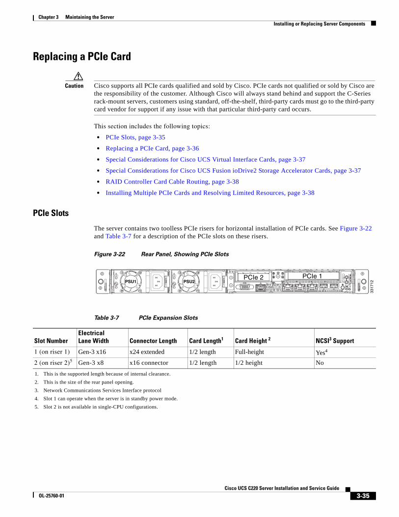
3-35Cisco UCS C220 Server Installation and Service Guide
OL-25760-01
Chapter 3 Maintaining the ServerInstalling or Replacing Server Components
Replacing a PCIe Card
Caution Cisco supports all PCIe cards qualified and sold by Cisco. PCIe cards not qualified or sold by Cisco are the responsibility of the customer. Although Cisco will always stand behind and support the C-Series rack-mount servers, customers using standard, off-the-shelf, third-party cards must go to the third-party card vendor for support if any issue with that particular third-party card occurs.
This section includes the following topics:
• PCIe Slots, page 3-35
• Replacing a PCIe Card, page 3-36
• Special Considerations for Cisco UCS Virtual Interface Cards, page 3-37
• Special Considerations for Cisco UCS Fusion ioDrive2 Storage Accelerator Cards, page 3-37
• RAID Controller Card Cable Routing, page 3-38
• Installing Multiple PCIe Cards and Resolving Limited Resources, page 3-38
PCIe Slots
The server contains two toolless PCIe risers for horizontal installation of PCIe cards. See Figure 3-22 and Table 3-7 for a description of the PCIe slots on these risers.
Figure 3-22 Rear Panel, Showing PCIe Slots
PSU1PSU1 PSU2PSU2PSU1 PSU2
3317
12
PCIe 2 PCIe 1
Table 3-7 PCIe Expansion Slots
Slot NumberElectrical Lane Width Connector Length Card Length1
1. This is the supported length because of internal clearance.
Card Height 2
2. This is the size of the rear panel opening.
NCSI3 Support
3. Network Communications Services Interface protocol
1 (on riser 1) Gen-3 x16 x24 extended 1/2 length Full-height Yes4
4. Slot 1 can operate when the server is in standby power mode.
2 (on riser 2)5
5. Slot 2 is not available in single-CPU configurations.
Gen-3 x8 x16 connector 1/2 length 1/2 height No
3-36Cisco UCS C220 Server Installation and Service Guide
OL-25760-01
Chapter 3 Maintaining the ServerInstalling or Replacing Server Components
Replacing a PCIe Card
Note If you are installing a Cisco UCS Virtual Interface Card, there are prerequisite considerations. See Special Considerations for Cisco UCS Virtual Interface Cards, page 3-37.
Note If you are installing a RAID controller card, see RAID Controller Considerations, page C-1 for more information about supported cards and cabling.
To install or replace a PCIe card, follow these steps:
Step 1 Remove a PCIe card (or a blank filler panel) from the PCIe riser:
a. Shut down and power off the server as described in the “Shutting Down and Powering Off the Server” section on page 3-7.
b. Slide the server out the front of the rack far enough so that you can remove the top cover. You might have to detach cables from the rear panel to provide clearance.
Caution If you cannot safely view and access the component, remove the server from the rack.
c. Remove the top cover as described in the “Removing and Replacing the Server Top Cover” section on page 3-8.
d. Remove any cables from the ports of the PCIe card that you are replacing.
Tip Label the cables when you disconnect them to aid correct connection to the new card.
e. Lift straight up on both ends of the PCIe riser to disengage it from the socket on the motherboard.
f. Pull evenly on both ends of the PCIe card to remove it from the socket on the PCIe riser.
If the riser has no card, remove the blanking panel from the rear opening of the riser.
Step 2 Install a new PCIe card:
a. Align the new PCIe card with the empty socket on the PCIe riser.
Note Align and insert the card’s rear panel tab into the riser’s rear panel opening at the same time you align the card with the empty socket.
b. Push down evenly on both ends of the card until it is fully seated in the socket.
c. Ensure that the card rear panel tab sits flat against the PCIe riser rear panel opening.
d. Position the PCIe riser over its socket on the motherboard and over the alignment features (see Figure 3-21).
e. Carefully push down on both ends of the PCIe riser to fully engage its circuit board connector with the socket on the motherboard.
f. Replace the top cover.
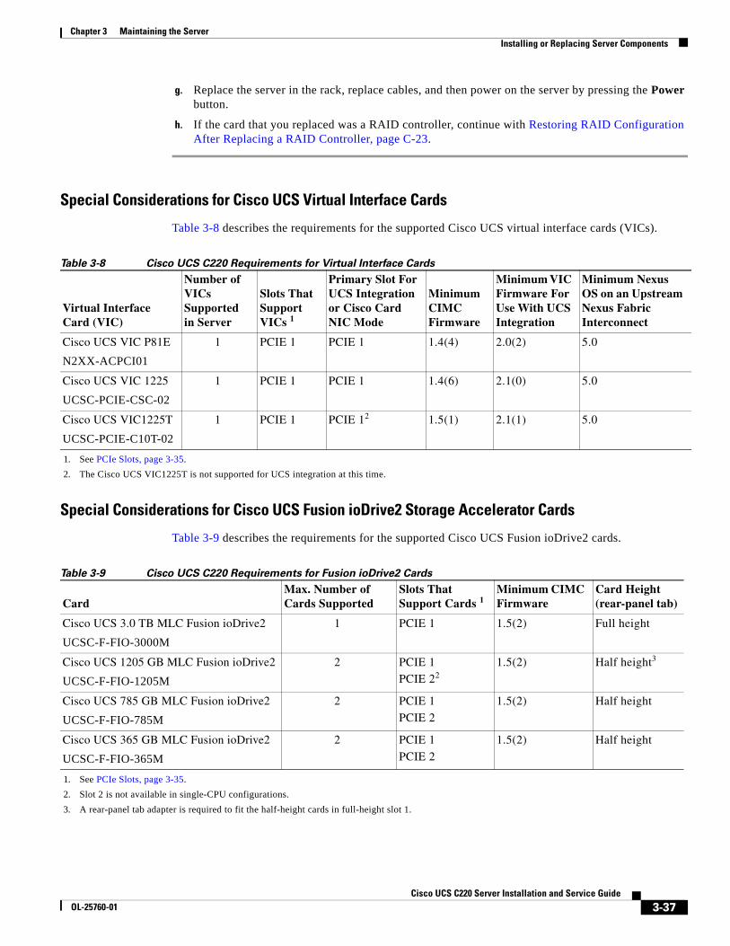
3-37Cisco UCS C220 Server Installation and Service Guide
OL-25760-01
Chapter 3 Maintaining the ServerInstalling or Replacing Server Components
g. Replace the server in the rack, replace cables, and then power on the server by pressing the Power button.
h. If the card that you replaced was a RAID controller, continue with Restoring RAID Configuration After Replacing a RAID Controller, page C-23.
Special Considerations for Cisco UCS Virtual Interface Cards
Table 3-8 describes the requirements for the supported Cisco UCS virtual interface cards (VICs).
Special Considerations for Cisco UCS Fusion ioDrive2 Storage Accelerator Cards
Table 3-9 describes the requirements for the supported Cisco UCS Fusion ioDrive2 cards.
Table 3-8 Cisco UCS C220 Requirements for Virtual Interface Cards
Virtual Interface Card (VIC)
Number of VICs Supported in Server
Slots That Support VICs 1
1. See PCIe Slots, page 3-35.
Primary Slot For UCS Integration or Cisco Card NIC Mode
Minimum CIMC Firmware
Minimum VIC Firmware For Use With UCS Integration
Minimum Nexus OS on an Upstream Nexus Fabric Interconnect
Cisco UCS VIC P81E
N2XX-ACPCI01
1 PCIE 1 PCIE 1 1.4(4) 2.0(2) 5.0
Cisco UCS VIC 1225
UCSC-PCIE-CSC-02
1 PCIE 1 PCIE 1 1.4(6) 2.1(0) 5.0
Cisco UCS VIC1225T
UCSC-PCIE-C10T-02
1 PCIE 1 PCIE 12
2. The Cisco UCS VIC1225T is not supported for UCS integration at this time.
1.5(1) 2.1(1) 5.0
Table 3-9 Cisco UCS C220 Requirements for Fusion ioDrive2 Cards
CardMax. Number of Cards Supported
Slots That Support Cards 1
1. See PCIe Slots, page 3-35.
Minimum CIMC Firmware
Card Height (rear-panel tab)
Cisco UCS 3.0 TB MLC Fusion ioDrive2
UCSC-F-FIO-3000M
1 PCIE 1 1.5(2) Full height
Cisco UCS 1205 GB MLC Fusion ioDrive2
UCSC-F-FIO-1205M
2 PCIE 1
PCIE 22
2. Slot 2 is not available in single-CPU configurations.
1.5(2) Half height3
3. A rear-panel tab adapter is required to fit the half-height cards in full-height slot 1.
Cisco UCS 785 GB MLC Fusion ioDrive2
UCSC-F-FIO-785M
2 PCIE 1
PCIE 2
1.5(2) Half height
Cisco UCS 365 GB MLC Fusion ioDrive2
UCSC-F-FIO-365M
2 PCIE 1
PCIE 2
1.5(2) Half height
3-38Cisco UCS C220 Server Installation and Service Guide
OL-25760-01
Chapter 3 Maintaining the ServerInstalling or Replacing Server Components
RAID Controller Card Cable Routing
If the PCIe card that you are installing or replacing is a RAID controller card, see RAID Controller Considerations, page C-1 for required cables and cable routing guidelines.
Installing Multiple PCIe Cards and Resolving Limited Resources
When a large number of PCIe add-on cards are installed in the server, the system may run out of the following resources required for PCIe devices:
• Option ROM memory space
• 16-bit I/O space
The topics in this section provide guidelines for resolving the issues related to these limited resources.
• Resolving Insufficient Memory Space to Execute Option ROMs, page 3-38
• Resolving Insufficient 16-Bit I/O Space, page 3-39
Resolving Insufficient Memory Space to Execute Option ROMs
The system has very limited memory to execute PCIe legacy option ROMs, so when a large number of PCIe add-on cards are installed in the server, the system BIOS might not able to execute all of the option ROMs. The system BIOS loads and executes the option ROMs in the order that the PCIe cards are enumerated (Slot 1, Slot 2, Slot 3, etc.).
If the system BIOS does not have sufficient memory space to load any PCIe option ROM, it skips loading that option ROM, reports a system event log (SEL) event to the CIMC controller and reports the following error in the Error Manager page of the BIOS Setup utility:
ERROR CODE SEVERITY INSTANCE DESCRIPTION146 Major N/A PCI out of resources error.
Major severity requires userintervention but does notprevent system boot.
To resolve this issue, disable the Option ROMs that are not needed for system booting. The BIOS Setup Utility provides the setup options to enable or disable the Option ROMs at the PCIe slot level for the PCIe expansion slots and at the port level for the onboard NICs. These options can be found in the BIOS Setup Utility Advanced PCI Configuration page.
• Guidelines for RAID controller booting:
If the server is configured to boot primarily from RAID storage, make sure that the option ROMs for the slots where your RAID controllers installed are enabled in the BIOS, depending on your RAID controller configuration.
If the RAID controller does not appear in the system boot order even with the option ROMs for those slots are enabled, the RAID controller option ROM might not have sufficient memory space to execute. In that case, disable other option ROMs that are not needed for the system configuration to free up some memory space for the RAID controller option ROM.
See also Factory-Default Option ROM Settings, page C-5.
• Guidelines for onboard NIC PXE booting:
If the system is configured to primarily perform PXE boot from onboard NICs, make sure that the option ROMs for the onboard NICs to be booted from are enabled in the BIOS Setup Utility. Disable other option ROMs that are not needed to create sufficient memory space for the onboard NICs.
3-39Cisco UCS C220 Server Installation and Service Guide
OL-25760-01
Chapter 3 Maintaining the ServerInstalling or Replacing Server Components
Resolving Insufficient 16-Bit I/O Space
The system has only 64 KB of legacy 16-bit I/O resources available. This 64 KB of I/O space is divided between the CPUs in the system because the PCIe controller is integrated into the CPUs. This server BIOS has the capability to dynamically detect the 16-bit I/O resource requirement for each CPU and then balance the 16-bit I/O resource allocation between the CPUs accordingly during the PCI bus enumeration phase of the BIOS POST.
When a large number of PCIe cards are installed in the system, the system BIOS might not have sufficient I/O space for some PCIe devices. If the system BIOS is not able to allocate the required I/O resources for any PCIe devices, the following symptoms have been observed:
• The system might get stuck in an infinite reset loop.
• The BIOS might appear to hang while initializing PCIe devices.
• The PCIe option ROMs might take excessive time to complete, which appears to lock up the system.
• PCIe boot devices might not be accessible from the BIOS.
• PCIe option ROMs might report initialization errors. These errors are seen before the BIOS passes control to the operating system.
• The keyboard might not work.
To work around this problem, rebalance the 16-bit I/O load using the following methods:
1. Physically remove any unused PCIe cards.
2. If the system has one or more Cisco virtual interface cards (VICs) installed, disable the PXE boot on the VICs that are not required for the system boot configuration by using the Network Adapters page in the CIMC WebUI to free up some 16-bit I/O resources. Each VIC uses a minimum 16 KB of 16-bit I/O resource, so disabling PXE boot on Cisco VICs would free up some 16-bit I/O resources that can be used for other PCIe cards that are installed in the system.
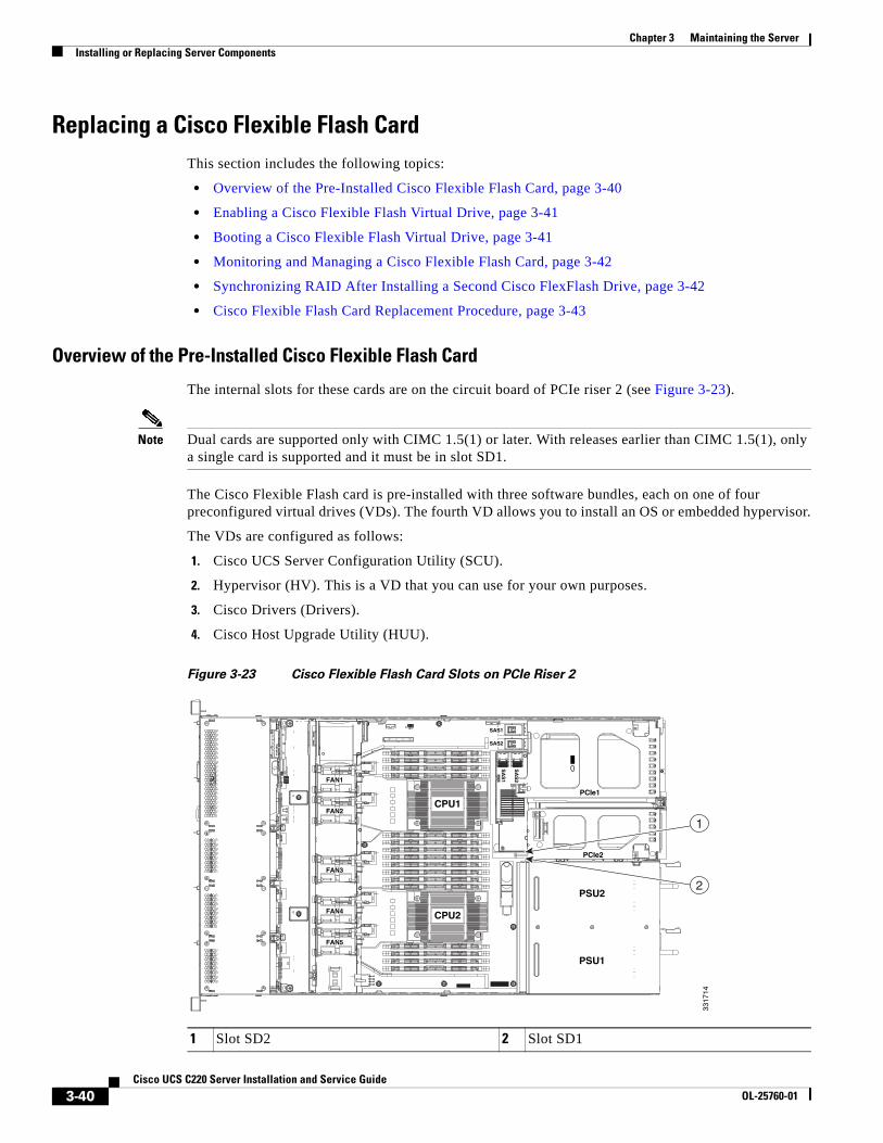
3-40Cisco UCS C220 Server Installation and Service Guide
OL-25760-01
Chapter 3 Maintaining the ServerInstalling or Replacing Server Components
Replacing a Cisco Flexible Flash CardThis section includes the following topics:
• Overview of the Pre-Installed Cisco Flexible Flash Card, page 3-40
• Enabling a Cisco Flexible Flash Virtual Drive, page 3-41
• Booting a Cisco Flexible Flash Virtual Drive, page 3-41
• Monitoring and Managing a Cisco Flexible Flash Card, page 3-42
• Synchronizing RAID After Installing a Second Cisco FlexFlash Drive, page 3-42
• Cisco Flexible Flash Card Replacement Procedure, page 3-43
Overview of the Pre-Installed Cisco Flexible Flash Card
The internal slots for these cards are on the circuit board of PCIe riser 2 (see Figure 3-23).
Note Dual cards are supported only with CIMC 1.5(1) or later. With releases earlier than CIMC 1.5(1), only a single card is supported and it must be in slot SD1.
The Cisco Flexible Flash card is pre-installed with three software bundles, each on one of four preconfigured virtual drives (VDs). The fourth VD allows you to install an OS or embedded hypervisor.
The VDs are configured as follows:
1. Cisco UCS Server Configuration Utility (SCU).
2. Hypervisor (HV). This is a VD that you can use for your own purposes.
3. Cisco Drivers (Drivers).
4. Cisco Host Upgrade Utility (HUU).
Figure 3-23 Cisco Flexible Flash Card Slots on PCIe Riser 2
1 Slot SD2 2 Slot SD1
FAN1FAN1FAN1
FAN2FAN2FAN2
FAN3FAN3FAN3
FAN4FAN4FAN4FAN4
FAN5FAN5FAN5
PSU2
PCIe1
PCIe2
PSU1
CPU1
CPU2
SAS1
SAS2
SA
S1
SA
S2
3317
14
1
2
3-41Cisco UCS C220 Server Installation and Service Guide
OL-25760-01
Chapter 3 Maintaining the ServerInstalling or Replacing Server Components
Enabling a Cisco Flexible Flash Virtual Drive
Each of the VDs on the pre-installed Cisco Flexible Flash card can be separately enabled or hidden from the host. The default as shipped from the factory is for all VDs to be hidden.
To enable VDs and expose them to the host, follow these steps:
Step 1 Log in to CIMC interface for the server, using the IP address of the server.
Step 2 Navigate through GUI tabs to Server > Inventory > Storage.
Step 3 Click FlexFlash-0 in the Storage Adapters list.
Step 4 Click on Configure Operational Profile in the Actions area.
The Operational Profile dialog opens.
Step 5 Check the box for each VD that you want to enable and expose to the host, then click Save Changes.
Booting a Cisco Flexible Flash Virtual Drive
When you want to access the Cisco SCU or Cisco HUU software, you boot its VD with a one-time boot option. When you want to boot the hypervisor (HV) VD, you boot it with a permanent boot order selection. See the following topics in this section:
• Booting the Cisco SCU and Cisco HUU Software VDs, page 3-41
• Booting the Hypervisor VD, page 3-41
Booting the Cisco SCU and Cisco HUU Software VDs
You can access the preinstalled Cisco SCU and Cisco HUU software bundles on a Cisco Flexible Flash card by booting their respective VDs with a one-time boot option:
Step 1 Enable the SCU or HUU VD.
See Enabling a Cisco Flexible Flash Virtual Drive, page 3-41.
Step 2 In the CIMC GUI interface, navigate through the tabs to Server > BIOS.
Step 3 Click Configure Boot Override Priority.
The Boot Override Priority dialog opens.
Step 4 Pull down the menu and select SCU or HUU, then click OK.
Step 5 Reboot the server.
The server boots the selected VD.
Note This is a one-time boot option. After running Cisco SCU or Cisco HUU, the server returns to its previously configured boot path.
Booting the Hypervisor VD
You can boot the hypervisor (HV) VD with a more permanent boot selection. (To change the boot order one time, use the procedure in Booting the Cisco SCU and Cisco HUU Software VDs, page 3-41.
3-42Cisco UCS C220 Server Installation and Service Guide
OL-25760-01
Chapter 3 Maintaining the ServerInstalling or Replacing Server Components
To permanently set the boot order for an HV VD, use the following steps:
Step 1 Boot the server and watch for the prompt to press F2 to open the BIOS Setup utility.
Step 2 When prompted, press F2 to open the BIOS Setup utility.
Step 3 Navigate to the Boot Options tab.
Step 4 Use the Boot Options screen to set the HV VD to your desired boot order for the server.
Monitoring and Managing a Cisco Flexible Flash Card
You can monitor and manage your installed Cisco Flexible Flash cards by using the CIMC GUI interface or the CLI interface. See the Cisco UCS C-Series Rack-Mount Server Configuration Guide or the Cisco UCS C-Series Rack-Mount Server CLI Configuration Guide in the documentation roadmap linked below.
The links to these documents are in the C-Series documentation roadmap:
http://www.cisco.com/go/unifiedcomputing/c-series-doc
Synchronizing RAID After Installing a Second Cisco FlexFlash Drive
After you install or replace a second Cisco FlexFlash drive, you must synchronize the RAID partition by using the Cisco UCS Server Configuration Utility (SCU).
The SCU provides an option to synchronize the Hypervisor VD, configured as a RAID-1 disk. This feature is available only when both Cisco FlexFlash drive slots are populated.
When one member slot of the SD card is corrupt, use this option to synchronize the hypervisor data across two members of the RAID-1 virtual disk. You can initiate this synchronization only if two cards are detected and the RAID-1 group is determined as unhealthy (one member is corrupt).
Step 1 Click the Hypervisor Sync icon on the toolbar of the SCU interface.
A dialog prompts you to confirm that you want to synchronize the Hypervisor RAID.
Step 2 Click Yes.
A dialog is displayed when the synchronization is complete.
Step 3 Click OK.
After you click OK, the Hypervisor Sync icon on the toolbar is greyed out.
For more information about the utility, see the Cisco UCS Server Configuration Utility User Guide.
3-43Cisco UCS C220 Server Installation and Service Guide
OL-25760-01
Chapter 3 Maintaining the ServerInstalling or Replacing Server Components
Cisco Flexible Flash Card Replacement Procedure
To install or replace a Cisco Flexible Flash card, follow these steps:
Step 1 Remove the Cisco Flexible Flash card that you are replacing. See Figure 3-23:
a. Power off the server as described in the “Shutting Down and Powering Off the Server” section on page 3-7.
b. Slide the server out the front of the rack far enough so that you can remove the top cover. You might have to detach cables from the rear panel to provide clearance.
Caution If you cannot safely view and access the component, remove the server from the rack.
c. Remove the top cover as described in “Removing and Replacing the Server Top Cover” section on page 3-8.
d. Locate the Cisco Flexible Flash card that you are replacing on PCIe riser 2. See Figure 3-23.
e. Push down on the top of the Cisco Flexible Flash card, then release it to allow it to spring up in the slot.
f. Remove the Cisco Flexible Flash card from the slot.
g. Wait 10 seconds for the Cisco Flexible Flash management software to recognize and react to the absence of the card.
3-44Cisco UCS C220 Server Installation and Service Guide
OL-25760-01
Chapter 3 Maintaining the ServerInstalling or Replacing Server Components
Step 2 Install a Cisco Flexible Flash card:
Note To be usable for Cisco Flexible Flash, an SD card must be at least 16 GB in size.
Note Any SD card that is installed into the Cisco Flexible Flash slot is configured with the VD partitioning described in Overview of the Pre-Installed Cisco Flexible Flash Card, page 3-40. This overwrites data on the SD card where Cisco stores the configuration metadata.
a. Insert the Cisco Flexible Flash card into the slot with the label side facing outward.
Note Dual cards are supported only with CIMC 1.5(1) or later. With releases earlier than CIMC 1.5(1), only a single card is supported and it must be in slot SD1 (see Figure 3-23).
b. Press down on the top of the card until it clicks in the slot and stays in place.
c. Replace the top cover.
d. Replace the server in the rack, replace cables, and then power on the server by pressing the Power button.
3-45Cisco UCS C220 Server Installation and Service Guide
OL-25760-01
Chapter 3 Maintaining the ServerInstalling or Replacing Server Components
Replacing the LSI RAID Battery Backup Unit or SuperCap Power ModuleThis server supports installation of one RAID battery backup unit (BBU) or one SuperCap Power Module (SCPM). The unit mounts to a clip on the removable air baffle (see Figure 3-24).
Note If you are replacing a BBU on an older card, order the iBBU09 battery backup unit (UCS-RAID-BBU=). The newer SuperCap power module is not compatible with older, non-CacheVault cards.
The SCPM provides approximately 3 years of backup for the disk write-back cache DRAM in the case of sudden power loss by offloading the cache to the NAND flash.
Warning There is danger of explosion if the battery is replaced incorrectly. Replace the battery only with the same or equivalent type recommended by the manufacturer. Dispose of used batteries according to the manufacturer’s instructions.Statement 1015
To replace the RAID controller BBU or SCPM, follow these steps:
Step 1 Remove a backup unit (see Figure 3-24).
a. Power off the server as described in the “Shutting Down and Powering Off the Server” section on page 3-7.
b. Slide the server out the front of the rack far enough so that you can remove the top cover. You might have to detach cables from the rear panel to provide clearance.
Caution If you cannot safely view and access the component, remove the server from the rack.
c. Remove the top cover as described in the “Removing and Replacing the Server Top Cover” section on page 3-8.
d. Disconnect the cable from the existing backup unit.
e. Slide the backup unit free of the clips on the air baffle mounting point (see Figure 3-24).
Step 2 Install a new backup unit:
a. Slide the new backup unit into the clips on the air baffle mounting point.
b. Connect the cable from the RAID controller to the new backup unit.
c. Replace the top cover.
d. Replace the server in the rack, replace cables, and then power on the server by pressing the Power button.
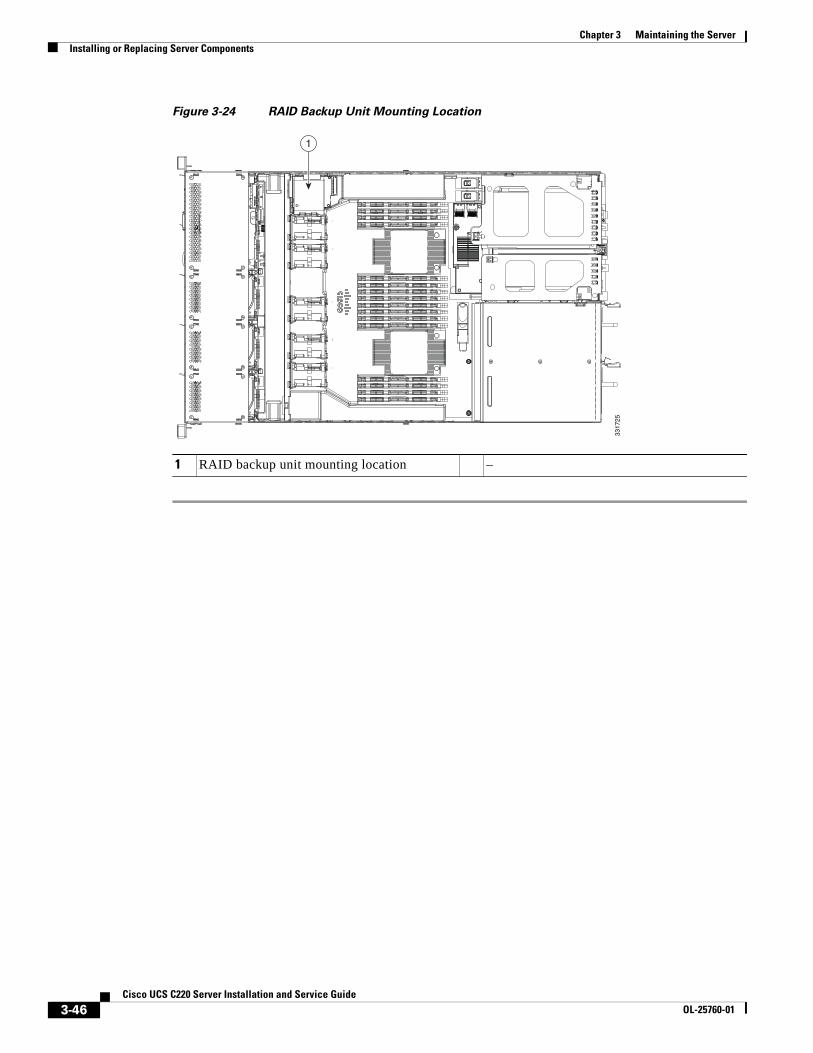
3-46Cisco UCS C220 Server Installation and Service Guide
OL-25760-01
Chapter 3 Maintaining the ServerInstalling or Replacing Server Components
Figure 3-24 RAID Backup Unit Mounting Location
1 RAID backup unit mounting location –
1
3317
25
3-47Cisco UCS C220 Server Installation and Service Guide
OL-25760-01
Chapter 3 Maintaining the ServerInstalling or Replacing Server Components
Installing a Trusted Platform Module The trusted platform module (TPM) is a small circuit board that attaches to a motherboard socket. The socket location is on the motherboard, below PCIe riser 1 (see Figure 3-25).
Note For security purposes, the TPM is installed with a one-way screw. It cannot be removed with a standard screwdriver.
To install a trusted platform module (TPM), follow these steps:
Step 1 Prepare the server for component installation.
a. Power off the server as described in the “Shutting Down and Powering Off the Server” section on page 3-7.
b. Slide the server out the front of the rack far enough so that you can remove the top cover. You might have to detach cables from the rear panel to provide clearance.
Caution If you cannot safely view and access the component, remove the server from the rack.
c. Remove the top cover as described in the “Removing and Replacing the Server Top Cover” section on page 3-8.
d. Is there a card installed in PCIe riser 1? See Figure 3-25.
• If there is no card installed in PCIe riser 1, you can access the TPM socket. Go to Step 2.
• If there is a card installed in PCIe riser 1, remove PCIe riser 1 from the chassis. See Replacing a PCIe Riser, page 3-33 for details.
Step 2 Install a TPM (see Figure 3-25):
a. Locate the TPM socket on the motherboard, as shown in Figure 3-25.
b. Align the connector that is on the bottom of the TPM circuit board with the motherboard TPM socket. Align the screw hole and standoff on the TPM board with the screw hole adjacent to the TPM socket.
c. Push down evenly on the TPM to seat it in the motherboard socket.
d. Install the single one-way screw that secures the TPM to the motherboard.
e. If you removed PCIe riser 1, replace it now. Reconnect cables to the card in the riser.
f. Replace the top cover.
g. Replace the server in the rack and then power on the server by pressing the Power button.
Step 3 Enable the TPM:
a. Watch during bootup for the F2 prompt, and then press F2 to enter BIOS setup.
b. Log into the BIOS Setup utility with your BIOS Administrator password.
c. On the BIOS Setup utility screen, select the Advanced tab.
d. Select Trusted Computing to open the TPM Security Device Configuration screen.
e. Change TPM SUPPORT to Enabled.
f. Press F10 to save your settings and reboot the server.
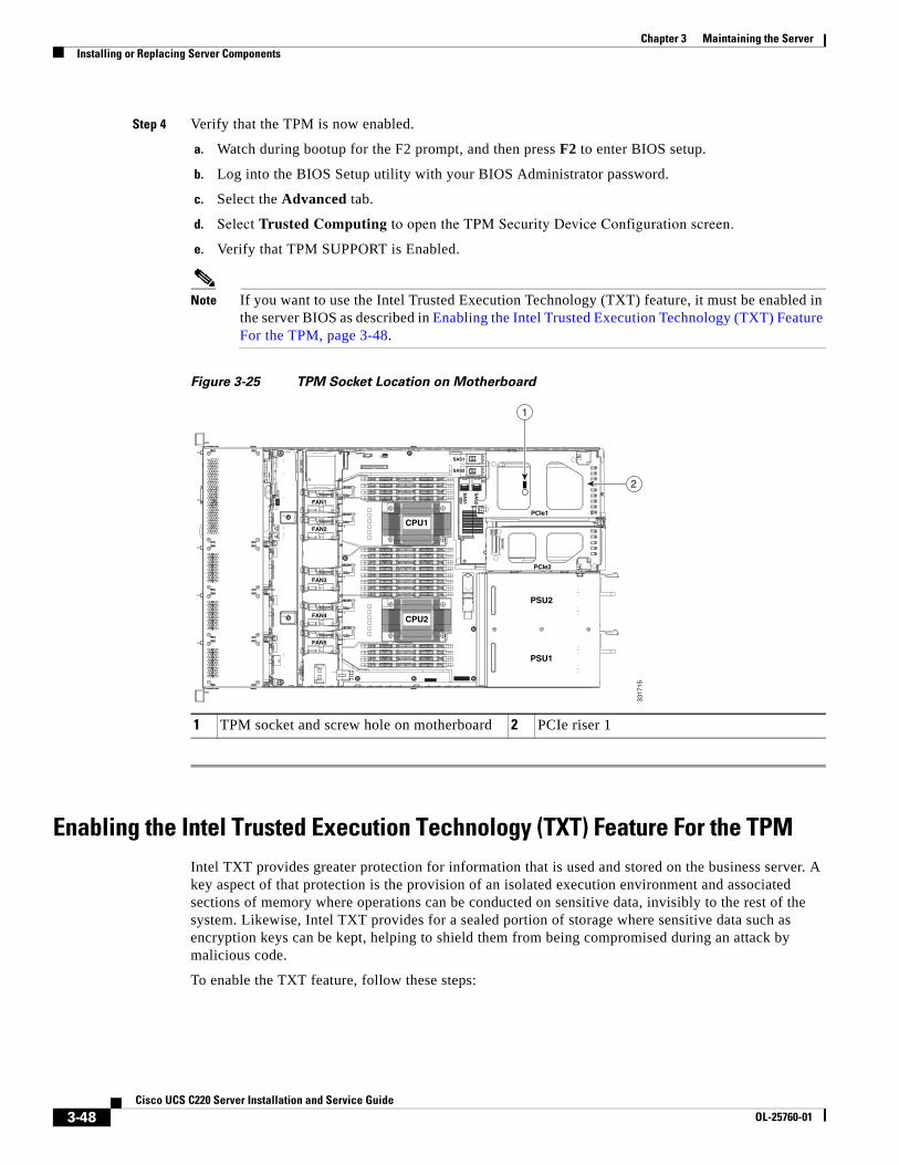
3-48Cisco UCS C220 Server Installation and Service Guide
OL-25760-01
Chapter 3 Maintaining the ServerInstalling or Replacing Server Components
Step 4 Verify that the TPM is now enabled.
a. Watch during bootup for the F2 prompt, and then press F2 to enter BIOS setup.
b. Log into the BIOS Setup utility with your BIOS Administrator password.
c. Select the Advanced tab.
d. Select Trusted Computing to open the TPM Security Device Configuration screen.
e. Verify that TPM SUPPORT is Enabled.
Note If you want to use the Intel Trusted Execution Technology (TXT) feature, it must be enabled in the server BIOS as described in Enabling the Intel Trusted Execution Technology (TXT) Feature For the TPM, page 3-48.
Figure 3-25 TPM Socket Location on Motherboard
Enabling the Intel Trusted Execution Technology (TXT) Feature For the TPMIntel TXT provides greater protection for information that is used and stored on the business server. A key aspect of that protection is the provision of an isolated execution environment and associated sections of memory where operations can be conducted on sensitive data, invisibly to the rest of the system. Likewise, Intel TXT provides for a sealed portion of storage where sensitive data such as encryption keys can be kept, helping to shield them from being compromised during an attack by malicious code.
To enable the TXT feature, follow these steps:
1 TPM socket and screw hole on motherboard 2 PCIe riser 1
FAN1FAN1FAN1
FAN2FAN2FAN2
FAN3FAN3FAN3
FAN4FAN4FAN4FAN4
FAN5FAN5FAN5
PSU2
PCIe1
PCIe2
PSU1
CPU1
CPU2
SAS1
SAS2
SA
S1
SA
S2
3317
15
2
1
3-49Cisco UCS C220 Server Installation and Service Guide
OL-25760-01
Chapter 3 Maintaining the ServerInstalling or Replacing Server Components
Step 1 Verify that a TPM is now installed and enabled in the server:
a. Either attach a VGA monitor and USB keyboard to the server, or log in remotely to the CIMC interface of the server and open a virtual KVM console window.
b. Reboot the server.
c. Watch during bootup for the F2 prompt, and then press F2 to enter BIOS setup.
d. Log in to the BIOS Setup utility with your BIOS Administrator password.
Note You must be logged in as the BIOS administrator to perform this procedure. If you have not done so already, set a BIOS administrator password on the Security tab of the BIOS Setup utility.
e. Select the Advanced tab.
f. On the Advanced tab, select Trusted Computing to open the TPM Security Device Configuration screen.
g. Verify that TPM SUPPORT is Enabled. If it is not, set TPM SUPPORT to Enabled.
h. Press Escape to return to the BIOS Setup utility Advanced tab.
Step 2 Enable the Intel Trusted Execution Technology (TXT) feature:
a. On the Advanced tab, select Intel TXT(LT-SX) Configuration to open the Intel TXT(LT-SX) Hardware Support screen.
Note The Intel Trusted Execution Technology feature can be enabled only when the server has a TPM installed on the TPM header.
b. Set TXT Support to Enabled.
Step 3 On the same screen, verify that the Intel Virtualization Technology (VT) and the Intel VT for Directed I/O (VT-d) features are enabled (the factory default).
a. On the Intel TXT(LT-SX) Hardware Support screen, verify that VT-d Support and VT Support are both listed as Enabled.
– If they are already enabled, skip to Step 4.
– If VT-d Support and VT Support are not enabled, continue with the next steps to enable them.
b. Press Escape to return to the BIOS Setup utility Advanced tab.
c. On the Advanced tab, select Processor Configuration to open the Processor Configuration screen.
d. Set Intel (R) VT and Intel (R) VT-d to Enabled.
Step 4 Press F10 to save your changes and exit the BIOS Setup utility.
Step 5 Verify that the Intel TXT, VT, and VT-d features are enabled:
a. Reboot the server.
b. Watch during bootup for the F2 prompt, and then press F2 to enter BIOS setup.
c. Select the Advanced tab.
d. Select Intel TXT(LT-SX) Configuration and verify that TXT Support, VT-d Support, and VT Support are Enabled.
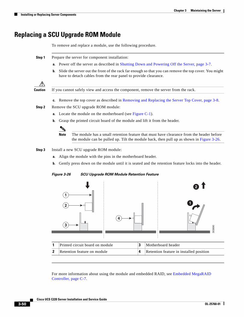
3-50Cisco UCS C220 Server Installation and Service Guide
OL-25760-01
Chapter 3 Maintaining the ServerInstalling or Replacing Server Components
Replacing a SCU Upgrade ROM ModuleTo remove and replace a module, use the following procedure.
Step 1 Prepare the server for component installation:
a. Power off the server as described in Shutting Down and Powering Off the Server, page 3-7.
b. Slide the server out the front of the rack far enough so that you can remove the top cover. You might have to detach cables from the rear panel to provide clearance.
Caution If you cannot safely view and access the component, remove the server from the rack.
c. Remove the top cover as described in Removing and Replacing the Server Top Cover, page 3-8.
Step 2 Remove the SCU upgrade ROM module:
a. Locate the module on the motherboard (see Figure C-1).
b. Grasp the printed circuit board of the module and lift it from the header.
Note The module has a small retention feature that must have clearance from the header before the module can be pulled up. Tilt the module back, then pull up as shown in Figure 3-26.
Step 3 Install a new SCU upgrade ROM module:
a. Align the module with the pins in the motherboard header.
b. Gently press down on the module until it is seated and the retention feature locks into the header.
Figure 3-26 SCU Upgrade ROM Module Retention Feature
For more information about using the module and embedded RAID, see Embedded MegaRAID Controller, page C-7.
1 Printed circuit board on module 3 Motherboard header
2 Retention feature on module 4 Retention feature in installed position
3036
903
4
2
1
1
2
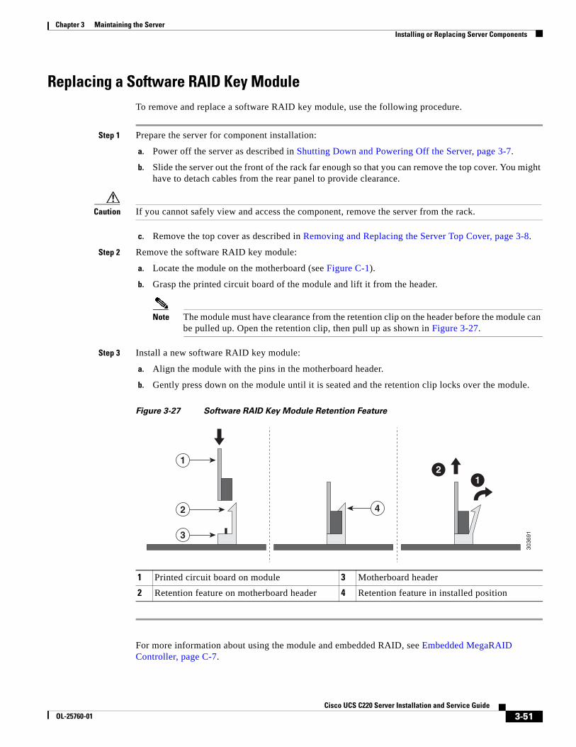
3-51Cisco UCS C220 Server Installation and Service Guide
OL-25760-01
Chapter 3 Maintaining the ServerInstalling or Replacing Server Components
Replacing a Software RAID Key ModuleTo remove and replace a software RAID key module, use the following procedure.
Step 1 Prepare the server for component installation:
a. Power off the server as described in Shutting Down and Powering Off the Server, page 3-7.
b. Slide the server out the front of the rack far enough so that you can remove the top cover. You might have to detach cables from the rear panel to provide clearance.
Caution If you cannot safely view and access the component, remove the server from the rack.
c. Remove the top cover as described in Removing and Replacing the Server Top Cover, page 3-8.
Step 2 Remove the software RAID key module:
a. Locate the module on the motherboard (see Figure C-1).
b. Grasp the printed circuit board of the module and lift it from the header.
Note The module must have clearance from the retention clip on the header before the module can be pulled up. Open the retention clip, then pull up as shown in Figure 3-27.
Step 3 Install a new software RAID key module:
a. Align the module with the pins in the motherboard header.
b. Gently press down on the module until it is seated and the retention clip locks over the module.
Figure 3-27 Software RAID Key Module Retention Feature
For more information about using the module and embedded RAID, see Embedded MegaRAID Controller, page C-7.
1 Printed circuit board on module 3 Motherboard header
2 Retention feature on motherboard header 4 Retention feature in installed position
3036
913
42
1
12
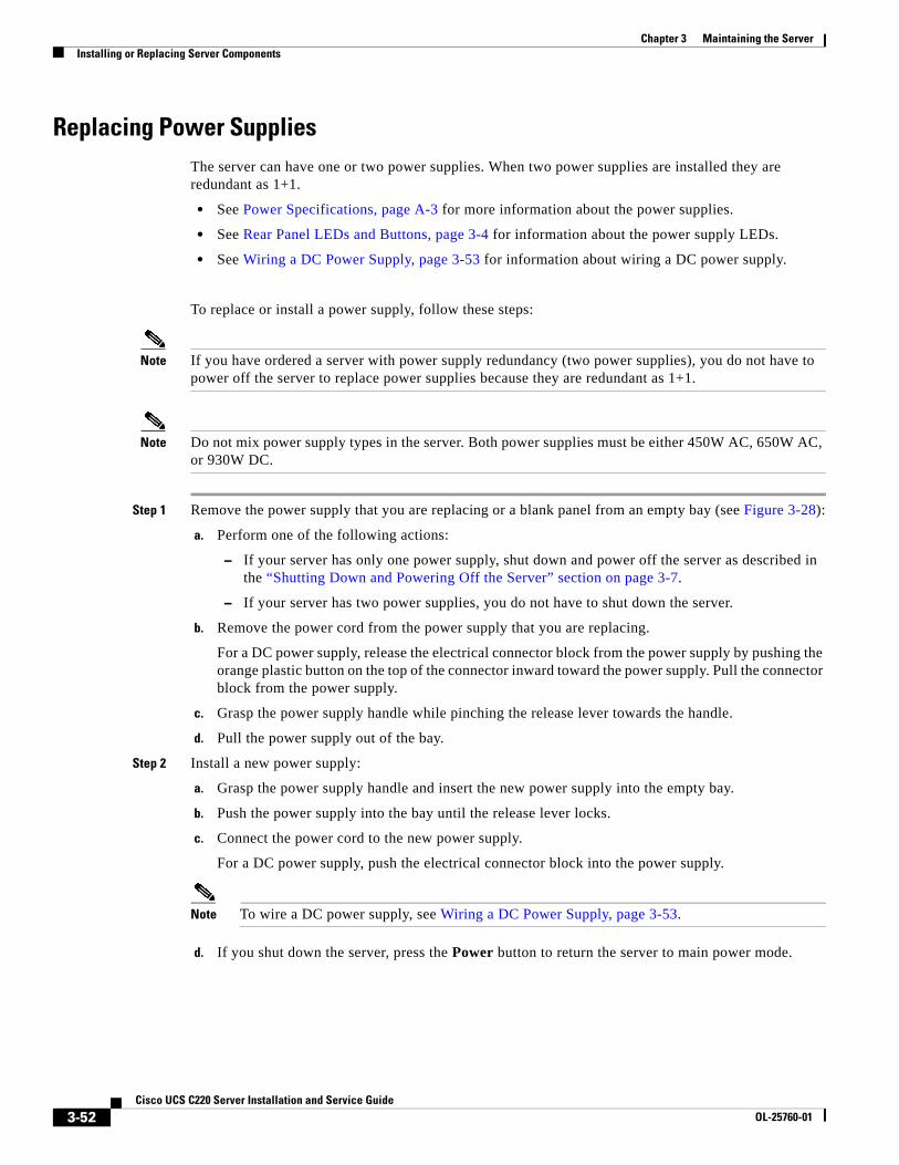
3-52Cisco UCS C220 Server Installation and Service Guide
OL-25760-01
Chapter 3 Maintaining the ServerInstalling or Replacing Server Components
Replacing Power Supplies The server can have one or two power supplies. When two power supplies are installed they are redundant as 1+1.
• See Power Specifications, page A-3 for more information about the power supplies.
• See Rear Panel LEDs and Buttons, page 3-4 for information about the power supply LEDs.
• See Wiring a DC Power Supply, page 3-53 for information about wiring a DC power supply.
To replace or install a power supply, follow these steps:
Note If you have ordered a server with power supply redundancy (two power supplies), you do not have to power off the server to replace power supplies because they are redundant as 1+1.
Note Do not mix power supply types in the server. Both power supplies must be either 450W AC, 650W AC, or 930W DC.
Step 1 Remove the power supply that you are replacing or a blank panel from an empty bay (see Figure 3-28):
a. Perform one of the following actions:
– If your server has only one power supply, shut down and power off the server as described in the “Shutting Down and Powering Off the Server” section on page 3-7.
– If your server has two power supplies, you do not have to shut down the server.
b. Remove the power cord from the power supply that you are replacing.
For a DC power supply, release the electrical connector block from the power supply by pushing the orange plastic button on the top of the connector inward toward the power supply. Pull the connector block from the power supply.
c. Grasp the power supply handle while pinching the release lever towards the handle.
d. Pull the power supply out of the bay.
Step 2 Install a new power supply:
a. Grasp the power supply handle and insert the new power supply into the empty bay.
b. Push the power supply into the bay until the release lever locks.
c. Connect the power cord to the new power supply.
For a DC power supply, push the electrical connector block into the power supply.
Note To wire a DC power supply, see Wiring a DC Power Supply, page 3-53.
d. If you shut down the server, press the Power button to return the server to main power mode.
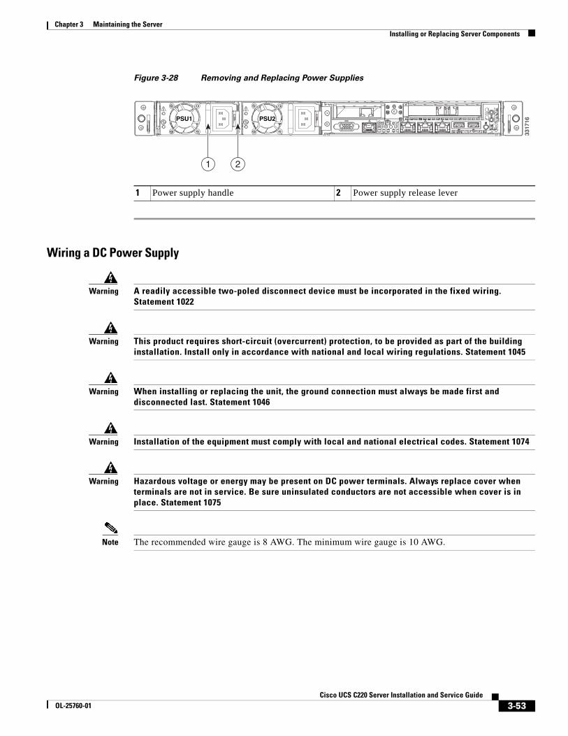
3-53Cisco UCS C220 Server Installation and Service Guide
OL-25760-01
Chapter 3 Maintaining the ServerInstalling or Replacing Server Components
Figure 3-28 Removing and Replacing Power Supplies
Wiring a DC Power Supply
Warning A readily accessible two-poled disconnect device must be incorporated in the fixed wiring. Statement 1022
Warning This product requires short-circuit (overcurrent) protection, to be provided as part of the building installation. Install only in accordance with national and local wiring regulations. Statement 1045
Warning When installing or replacing the unit, the ground connection must always be made first and disconnected last. Statement 1046
Warning Installation of the equipment must comply with local and national electrical codes. Statement 1074
Warning Hazardous voltage or energy may be present on DC power terminals. Always replace cover when terminals are not in service. Be sure uninsulated conductors are not accessible when cover is in place. Statement 1075
Note The recommended wire gauge is 8 AWG. The minimum wire gauge is 10 AWG.
1 Power supply handle 2 Power supply release lever
PSU1PSU1 PSU2PSU2PSU1 PSU2
1 2
3317
16
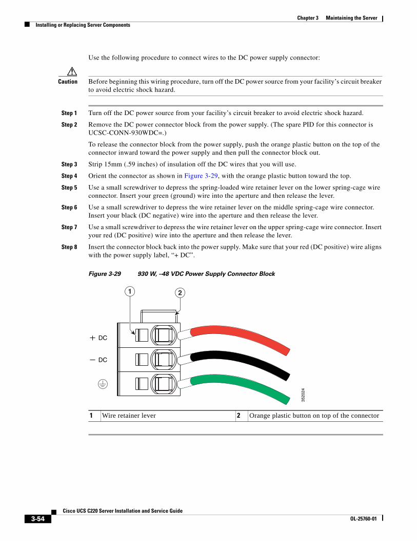
3-54Cisco UCS C220 Server Installation and Service Guide
OL-25760-01
Chapter 3 Maintaining the ServerInstalling or Replacing Server Components
Use the following procedure to connect wires to the DC power supply connector:
Caution Before beginning this wiring procedure, turn off the DC power source from your facility’s circuit breaker to avoid electric shock hazard.
Step 1 Turn off the DC power source from your facility’s circuit breaker to avoid electric shock hazard.
Step 2 Remove the DC power connector block from the power supply. (The spare PID for this connector is UCSC-CONN-930WDC=.)
To release the connector block from the power supply, push the orange plastic button on the top of the connector inward toward the power supply and then pull the connector block out.
Step 3 Strip 15mm (.59 inches) of insulation off the DC wires that you will use.
Step 4 Orient the connector as shown in Figure 3-29, with the orange plastic button toward the top.
Step 5 Use a small screwdriver to depress the spring-loaded wire retainer lever on the lower spring-cage wire connector. Insert your green (ground) wire into the aperture and then release the lever.
Step 6 Use a small screwdriver to depress the wire retainer lever on the middle spring-cage wire connector. Insert your black (DC negative) wire into the aperture and then release the lever.
Step 7 Use a small screwdriver to depress the wire retainer lever on the upper spring-cage wire connector. Insert your red (DC positive) wire into the aperture and then release the lever.
Step 8 Insert the connector block back into the power supply. Make sure that your red (DC positive) wire aligns with the power supply label, “+ DC”.
Figure 3-29 930 W, –48 VDC Power Supply Connector Block
1 Wire retainer lever 2 Orange plastic button on top of the connector
DC
DC
21
3520
24
3-55Cisco UCS C220 Server Installation and Service Guide
OL-25760-01
Chapter 3 Maintaining the ServerInstalling or Replacing Server Components
Enabling or Disabling the Internal USB PortThe factory default is for all USB ports on the server to be enabled. However, the internal USB port can be enabled or disabled in the server BIOS. To enable or disable the internal USB port, follow these steps:
Step 1 Enter the BIOS Setup utility by pressing the F2 key when prompted during bootup.
Step 2 Navigate to the Advanced tab.
Step 3 On the Advanced tab, select USB Configuration.
Step 4 On the USB Configuration page, select USB Ports Configuration.
Step 5 Scroll to USB Port: Internal, press Enter, and then select either Enabled or Disabled from the pop-up menu.
Step 6 Press F10 to save and exit the utility.

3-56Cisco UCS C220 Server Installation and Service Guide
OL-25760-01
Chapter 3 Maintaining the ServerInstalling or Replacing Server Components
A-1Cisco UCS C220 Server Installation and Service Guide
OL-25760-01
A P P E N D I X AServer Specifications
This appendix lists the technical specifications for the server and includes the following sections:
• Physical Specifications, page A-1
• Environmental Specifications, page A-2
• Power Specifications, page A-3
Physical SpecificationsTable A-1 lists the physical specifications for the server.
Table A-1 Physical Specifications
Description Specification
Height 1.7 in. (4.3 cm)
Width 16.9 in. (42.9 cm)
Depth 28.5 in. (72.4 cm)
Weight (fully loaded chassis) 35.6 lb. (16.1 Kg)
A-2Cisco UCS C220 Server Installation and Service Guide
OL-25760-01
Appendix A Server SpecificationsEnvironmental Specifications
Environmental Specifications Table A-2 lists the environmental specifications for the server.
Table A-2 Environmental Specifications
Description Specification
Temperature, operating: 41 to 104°F (5 to 40°C)Derate the maximum temperature by 1°C per every 305 meters of altitude above sea level.
Temperature, non-operating –40 to 149°F (–40 to 65°C)
Humidity (RH), noncondensing 10 to 90%
Altitude, operating 0 to 10,000 feet
Altitude, non-operating 0 to 40,000 feet
Sound power levelMeasure A-weighted per ISO7779 LwAd (Bels)Operation at 73°F (23°C)
5.4
Sound pressure levelMeasure A-weighted per ISO7779 LpAm (dBA)Operation at 73°F (23°C)
37
A-3Cisco UCS C220 Server Installation and Service Guide
OL-25760-01
Appendix A Server SpecificationsPower Specifications
Power Specifications The power specifications for the power supply options are listed in the following sections:
• 450W AC Power Supply, page A-3
• 650W AC Power Supply, page A-4
• 930W DC Power Supply, page A-4
You can get more specific power information for your exact server configuration by using the Cisco UCS Power Calculator:
http://www.cisco.com/assets/cdc_content_elements/flash/dataCenter/cisco_ucs_power_calculator/
Note Do not mix power supply types in the server. Both power supplies must be identical.
450W AC Power SupplyTable A-3 lists the specifications for each 450 W AC power supply (Cisco part number UCSC-PSU-450W).
Table A-3 Power Supply Specifications
Description Specification
AC input voltage range Low range: 100 VAC to 120 VACHigh range: 200 VAC to 240 VAC
AC input frequency Range: 47 to 63 Hz (single phase, 50 to 60Hz nominal)
AC line input current (steady state) 6.0 A peak at 100 VAC3.0 A peak at 208 VAC
Maximum output power for each power supply
450 W
Power supply output voltage Main power: 12 VDC
Standby power: 12 VDC
A-4Cisco UCS C220 Server Installation and Service Guide
OL-25760-01
Appendix A Server SpecificationsPower Specifications
650W AC Power SupplyTable A-4 lists the specifications for each 650 W AC power supply (Cisco part number UCSC-PSU-650W).
930W DC Power SupplyTable A-5 lists the specifications for each 930 W DC power supply (Cisco part number UCSC-PSU-930WDC).
Table A-4 Power Supply Specifications
Description Specification
AC input voltage range 90 to 264 VAC (self-ranging, 180 to 264 VAC nominal)
AC input frequency Range: 47 to 63 Hz (single phase, 50 to 60Hz nominal)
AC line input current (steady state) 7.6 A peak at 100 VAC3.65 A peak at 208 VAC
Maximum output power for each power supply
650 W
Power supply output voltage Main power: 12 VDC
Standby power: 12 VDC
Table A-5 930 W DC Power Supply Specifications
Description Specification
Class RSP1
Input
DC input voltage range –48 to -60 VDC nominal (self-ranging, –40 to –72 VDC)
DC line input current (steady state) 23 A peak at –48 VDC
Output
12 V main power output 930 W
12 V standby power output 30 W
Power supply output voltage Main power: 12 VDC
Standby power: 12 VDC
B-1Cisco UCS C220 Server Installation and Service Guide
OL-25760-01
A P P E N D I X BPower Cord Specifications
This appendix provides supported power cable specifications.
Supported Power Cords and PlugsEach power supply has a separate power cord. Standard power cords or jumper power cords are available for connection to the server. The jumper power cords, for use in racks, are available as an optional alternative to the standard power cords.
Note Only the approved power cords or jumper power cords provided with the server are supported.
Table B-1 lists the power cords for the server power supplies.
Table B-1 Supported Power Cords for the Server
Description
Length Power Cord Reference IllustrationFeet Meters
SFS-250V-10A-ARPower Cord, 250 VAC 10 A IRAM 2073 Plug Argentina
8.2 2.5 Figure B-1
CAB-9K10A-AU250 VAC 10 A 3112 Plug, Australia
8.2 2.5 Figure B-2
SFS-250V-10A-CNPower Cord, 250 VAC 10 A GB 2009 PlugChina
8.2 2.5 Figure B-3
CAB-9K10A-EUPower Cord, 250 VAC 10 A M 2511 PlugEurope
8.2 2.5 Figure B-4
SFS-250V-10A-IDPower Cord, 250 VAC 16A EL-208 PlugSouth Africa, United Arab Emirates, India
8.2 2.5 Figure B-5
SFS-250V-10A-ISPower Cord, 250 VAC 10 A SI32 Plug Israel
8.2 2.5 Figure B-6
B-2Cisco UCS C220 Server Installation and Service Guide
OL-25760-01
Appendix B Power Cord SpecificationsSupported Power Cords and Plugs
CAB-9K10A-ITPower Cord, 250 VAC 10 A CEI 23-16 Plug Italy
8.2 2.5 Figure B-7
CAB-9K10A-SWPower Cord, 250 VAC 10 A MP232 Plug Switzerland
8.2 2.5 Figure B-8
CAB-9K10A-UKPower Cord, 250 VAC 10 A BS1363 Plug (13 A fuse)United Kingdom
8.2 2.5 Figure B-9
CAB-AC-250V/13APower Cord, 250 VAC 13 A IEC60320 Plug North America
6.6 2.0 Figure B-10
CAB-N5K6A-NAPower Cord, 250 VAC 13 A NEMA 6-15 Plug,North America
8.2 2.5 Figure B-11
CAB-9K12A-NAPower cord, 125 VAC, 13 A, NEMA 5-15 PlugNorth America
8.2 2.5 Figure B-12
CAB-C13-CBNCabinet Jumper Power Cord, 250 VAC 10 A, C13-C14 Connectors
2.2 0.68 Figure B-13
CAB-C13-C14-2MCabinet Jumper Power Cord, 250 VAC 10 A, C13-C14 Connectors
6.6 2.0 Figure B-14
CAB-C13-C14-ACCabinet Jumper Power Cord, 250 VAC 10 A, C13-C14 Connectors
9.8 3.0 Figure B-15
Table B-1 Supported Power Cords for the Server (continued)
Description
Length Power Cord Reference IllustrationFeet Meters
B-3Cisco UCS C220 Server Installation and Service Guide
OL-25760-01
Appendix B Power Cord SpecificationsSupported Power Cords and Plugs
AC Power Cord IllustrationsThis section includes the AC power cord illustrations. See Figure B-1 through Figure B-15.
Figure B-1 SFS-250V-10A-AR
Figure B-2 CAB-9K10A-AU
Figure B-3 SFS-250V-10A-CN
1865
71
2500 mm
Cordset rating: 10 A, 250/500 V MAXLength: 8.2 ft
Plug:EL 219
(IRAM 2073) Connector:EL 701
(IEC60320/C13)
Plug:EL 206
A.S. 3112-2000)
Cordset rating: 10 A, 250 V/500VLength: 2500mm
1865
81
Connector:EL 701C
(IEC 60320/C15)
Cordset rating 10A, 250V(2500 mm)
Plug:EL 218
(CCEE GB2009)
1865
73
Connector:EL 701
(IEC60320/C13)
B-4Cisco UCS C220 Server Installation and Service Guide
OL-25760-01
Appendix B Power Cord SpecificationsSupported Power Cords and Plugs
Figure B-4 CAB-9K10A-EU
Figure B-5 SFS-250V-10A-ID
Figure B-6 SFS-250V-10A-IS
Connector:VSCC15
Cordset rating: 10A/16 A, 250 VLength: 8 ft 2 in. (2.5 m)Plug:
M2511
1865
76
OVE
Cordset rating 16A, 250V(2500mm)
Plug:EL 208
1874
90
Connector:EL 701
Cordset rating 10A, 250V/500V MAX(2500 mm)
Plug:EL 212(SI-32)
1865
74
Connector:EL 701B
(IEC60320/C13)
EL-21216A250V
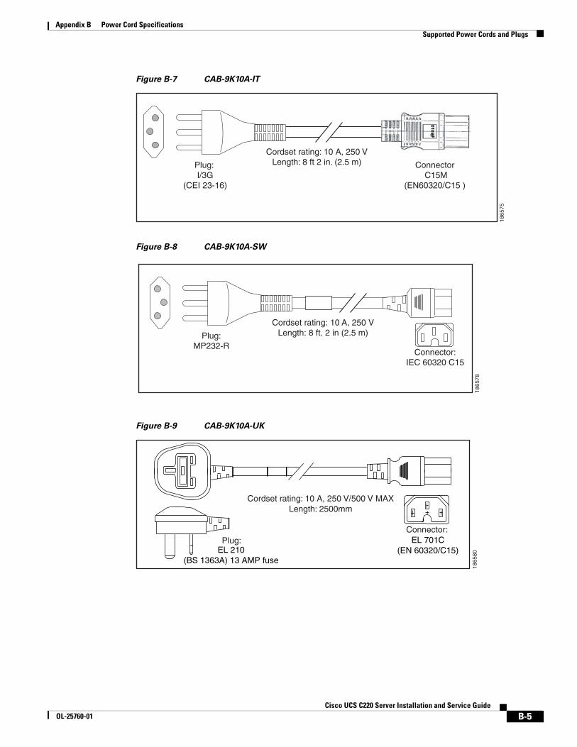
B-5Cisco UCS C220 Server Installation and Service Guide
OL-25760-01
Appendix B Power Cord SpecificationsSupported Power Cords and Plugs
Figure B-7 CAB-9K10A-IT
Figure B-8 CAB-9K10A-SW
Figure B-9 CAB-9K10A-UK
Plug: I/3G
(CEI 23-16)
Connector C15M
(EN60320/C15 )
Cordset rating: 10 A, 250 VLength: 8 ft 2 in. (2.5 m)
1865
75
Plug:MP232-R
Cordset rating: 10 A, 250 VLength: 8 ft. 2 in (2.5 m)
1865
78
Connector:IEC 60320 C15
Plug:
Cordset rating: 10 A, 250 V/500 V MAXLength: 2500mm
1865
80
Connector:EL 701C
(EN 60320/C15)EL 210(BS 1363A) 13 AMP fuse
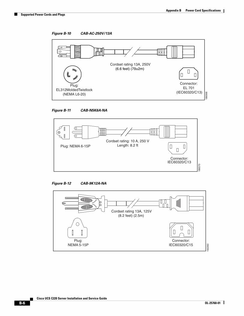
B-6Cisco UCS C220 Server Installation and Service Guide
OL-25760-01
Appendix B Power Cord SpecificationsSupported Power Cords and Plugs
Figure B-10 CAB-AC-250V/13A
Figure B-11 CAB-N5K6A-NA
Figure B-12 CAB-9K12A-NA
Cordset rating 13A, 250V(6.6 feet) (79±2m)
Plug:EL312MoldedTwistlock
(NEMA L6-20)
1865
68
Connector:EL 701
(IEC60320/C13)
Cordset rating: 10 A, 250 VLength: 8.2 ft
1865
70
Plug: NEMA 6-15P
Connector:IEC60320/C13
Connector:IEC60320/C15
Cordset rating 13A, 125V(8.2 feet) (2.5m)
Plug:NEMA 5-15P
1922
60
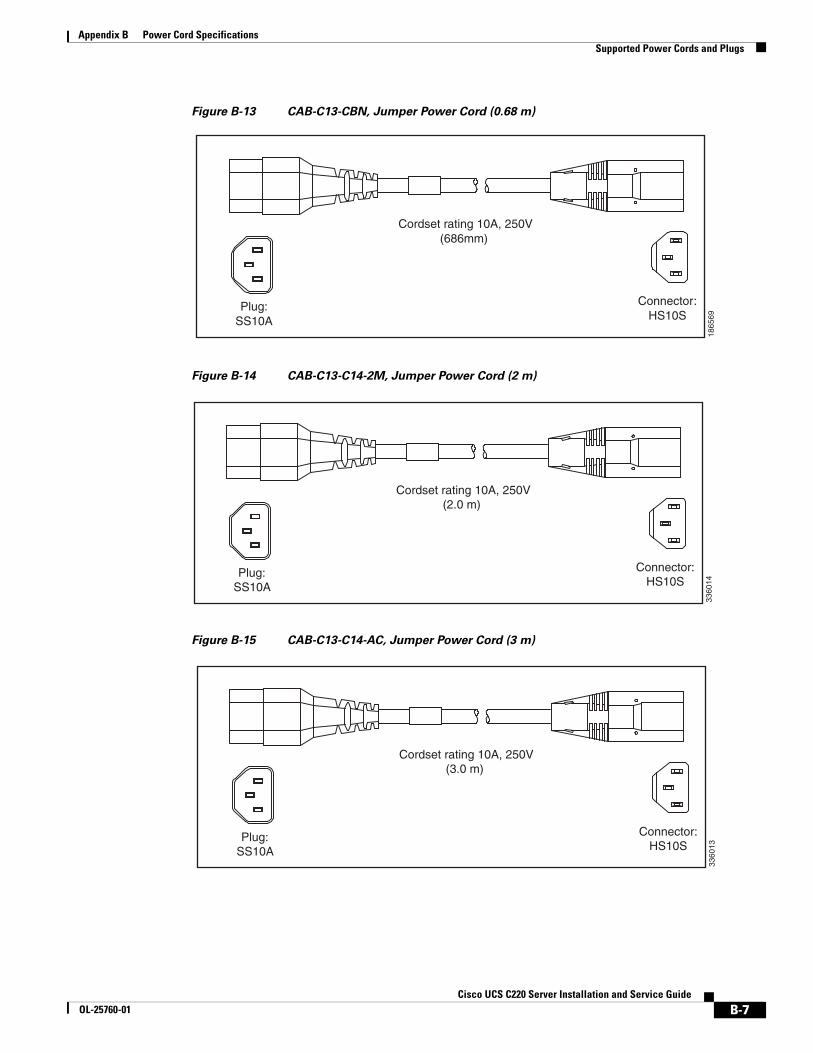
B-7Cisco UCS C220 Server Installation and Service Guide
OL-25760-01
Appendix B Power Cord SpecificationsSupported Power Cords and Plugs
Figure B-13 CAB-C13-CBN, Jumper Power Cord (0.68 m)
Figure B-14 CAB-C13-C14-2M, Jumper Power Cord (2 m)
Figure B-15 CAB-C13-C14-AC, Jumper Power Cord (3 m)
Cordset rating 10A, 250V(686mm)
Plug:SS10A
1865
69
Connector:HS10S
Cordset rating 10A, 250V(2.0 m)
Plug:SS10A
3360
14
Connector:HS10S
Cordset rating 10A, 250V(3.0 m)
Plug:SS10A
3360
13
Connector:HS10S

B-8Cisco UCS C220 Server Installation and Service Guide
OL-25760-01
Appendix B Power Cord SpecificationsSupported Power Cords and Plugs
C-1Cisco UCS C220 Server Installation and Service Guide
OL-25760-01
A P P E N D I X CRAID Controller Considerations
This appendix contains the following sections:
• Supported RAID Controllers and Required Cables, page C-2
• RAID Controller Migration, page C-6
• Factory-Default Option ROM Settings, page C-5
• Mixing Drive Types in RAID Groups, page C-4
• RAID Backup Units, page C-4
• RAID Controller Migration, page C-6
• Embedded MegaRAID Controller, page C-7
• RAID Controller Cabling, page C-19
• Restoring RAID Configuration After Replacing a RAID Controller, page C-23
• For More Information, page C-23
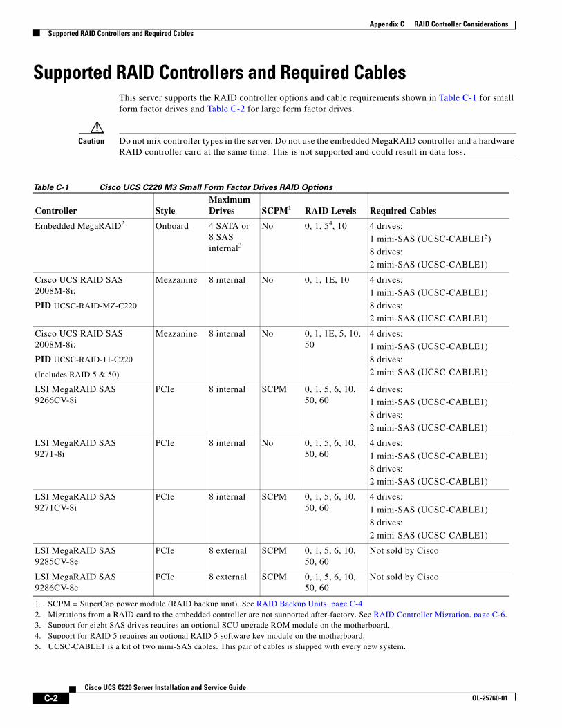
C-2Cisco UCS C220 Server Installation and Service Guide
OL-25760-01
Appendix C RAID Controller ConsiderationsSupported RAID Controllers and Required Cables
Supported RAID Controllers and Required CablesThis server supports the RAID controller options and cable requirements shown in Table C-1 for small form factor drives and Table C-2 for large form factor drives.
Caution Do not mix controller types in the server. Do not use the embedded MegaRAID controller and a hardware RAID controller card at the same time. This is not supported and could result in data loss.
Table C-1 Cisco UCS C220 M3 Small Form Factor Drives RAID Options
Controller StyleMaximum Drives SCPM1
1. SCPM = SuperCap power module (RAID backup unit). See RAID Backup Units, page C-4.
RAID Levels Required Cables
Embedded MegaRAID2
2. Migrations from a RAID card to the embedded controller are not supported after-factory. See RAID Controller Migration, page C-6.
Onboard 4 SATA or8 SASinternal3
3. Support for eight SAS drives requires an optional SCU upgrade ROM module on the motherboard.
No 0, 1, 54, 10
4. Support for RAID 5 requires an optional RAID 5 software key module on the motherboard.
4 drives:
1 mini-SAS (UCSC-CABLE15)
8 drives:
2 mini-SAS (UCSC-CABLE1)
5. UCSC-CABLE1 is a kit of two mini-SAS cables. This pair of cables is shipped with every new system.
Cisco UCS RAID SAS 2008M-8i:
PID UCSC-RAID-MZ-C220
Mezzanine 8 internal No 0, 1, 1E, 10 4 drives:
1 mini-SAS (UCSC-CABLE1)
8 drives:
2 mini-SAS (UCSC-CABLE1)
Cisco UCS RAID SAS 2008M-8i:
PID UCSC-RAID-11-C220
(Includes RAID 5 & 50)
Mezzanine 8 internal No 0, 1, 1E, 5, 10, 50
4 drives:
1 mini-SAS (UCSC-CABLE1)
8 drives:
2 mini-SAS (UCSC-CABLE1)
LSI MegaRAID SAS 9266CV-8i
PCIe 8 internal SCPM 0, 1, 5, 6, 10, 50, 60
4 drives:
1 mini-SAS (UCSC-CABLE1)
8 drives:
2 mini-SAS (UCSC-CABLE1)
LSI MegaRAID SAS 9271-8i
PCIe 8 internal No 0, 1, 5, 6, 10, 50, 60
4 drives:
1 mini-SAS (UCSC-CABLE1)
8 drives:
2 mini-SAS (UCSC-CABLE1)
LSI MegaRAID SAS 9271CV-8i
PCIe 8 internal SCPM 0, 1, 5, 6, 10, 50, 60
4 drives:
1 mini-SAS (UCSC-CABLE1)
8 drives:
2 mini-SAS (UCSC-CABLE1)
LSI MegaRAID SAS 9285CV-8e
PCIe 8 external SCPM 0, 1, 5, 6, 10, 50, 60
Not sold by Cisco
LSI MegaRAID SAS9286CV-8e
PCIe 8 external SCPM 0, 1, 5, 6, 10, 50, 60
Not sold by Cisco
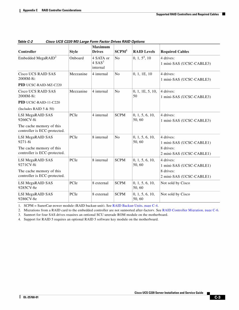
C-3Cisco UCS C220 Server Installation and Service Guide
OL-25760-01
Appendix C RAID Controller ConsiderationsSupported RAID Controllers and Required Cables
Table C-2 Cisco UCS C220 M3 Large Form Factor Drives RAID Options
Controller StyleMaximum Drives SCPM1
1. SCPM = SuperCap power module (RAID backup unit). See RAID Backup Units, page C-4.
RAID Levels Required Cables
Embedded MegaRAID2
2. Migrations from a RAID card to the embedded controller are not supported after-factory. See RAID Controller Migration, page C-6.
Onboard 4 SATA or4 SAS3internal
3. Support for four SAS drives requires an optional SCU upgrade ROM module on the motherboard.
No 0, 1, 54, 10
4. Support for RAID 5 requires an optional RAID 5 software key module on the motherboard.
4 drives:
1 mini-SAS (UCSC-CABLE3)
Cisco UCS RAID SAS 2008M-8i:
PID UCSC-RAID-MZ-C220
Mezzanine 4 internal No 0, 1, 1E, 10 4 drives:
1 mini-SAS (UCSC-CABLE3)
Cisco UCS RAID SAS 2008M-8i:
PID UCSC-RAID-11-C220
(Includes RAID 5 & 50)
Mezzanine 4 internal No 0, 1, 1E, 5, 10, 50
4 drives:
1 mini-SAS (UCSC-CABLE3)
LSI MegaRAID SAS 9266CV-8i
The cache memory of this controller is ECC-protected.
PCIe 4 internal SCPM 0, 1, 5, 6, 10, 50, 60
4 drives:
1 mini-SAS (UCSC-CABLE3)
LSI MegaRAID SAS 9271-8i
The cache memory of this controller is ECC-protected.
PCIe 8 internal No 0, 1, 5, 6, 10, 50, 60
4 drives:
1 mini-SAS (UCSC-CABLE1)
8 drives:
2 mini-SAS (UCSC-CABLE1)
LSI MegaRAID SAS 9271CV-8i
The cache memory of this controller is ECC-protected.
PCIe 8 internal SCPM 0, 1, 5, 6, 10, 50, 60
4 drives:
1 mini-SAS (UCSC-CABLE1)
8 drives:
2 mini-SAS (UCSC-CABLE1)
LSI MegaRAID SAS 9285CV-8e
PCIe 8 external SCPM 0, 1, 5, 6, 10, 50, 60
Not sold by Cisco
LSI MegaRAID SAS9286CV-8e
PCIe 8 external SCPM 0, 1, 5, 6, 10, 50, 60
Not sold by Cisco
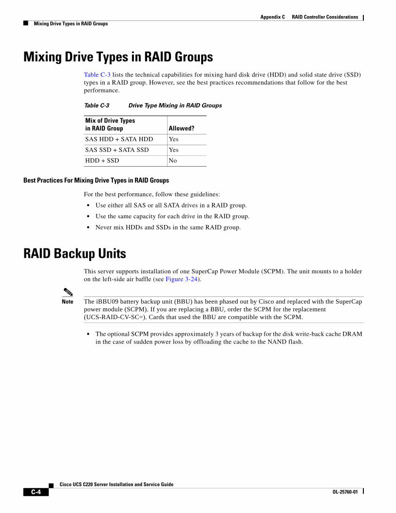
C-4Cisco UCS C220 Server Installation and Service Guide
OL-25760-01
Appendix C RAID Controller ConsiderationsMixing Drive Types in RAID Groups
Mixing Drive Types in RAID GroupsTable C-3 lists the technical capabilities for mixing hard disk drive (HDD) and solid state drive (SSD) types in a RAID group. However, see the best practices recommendations that follow for the best performance.
Best Practices For Mixing Drive Types in RAID Groups
For the best performance, follow these guidelines:
• Use either all SAS or all SATA drives in a RAID group.
• Use the same capacity for each drive in the RAID group.
• Never mix HDDs and SSDs in the same RAID group.
RAID Backup UnitsThis server supports installation of one SuperCap Power Module (SCPM). The unit mounts to a holder on the left-side air baffle (see Figure 3-24).
Note The iBBU09 battery backup unit (BBU) has been phased out by Cisco and replaced with the SuperCap power module (SCPM). If you are replacing a BBU, order the SCPM for the replacement (UCS-RAID-CV-SC=). Cards that used the BBU are compatible with the SCPM.
• The optional SCPM provides approximately 3 years of backup for the disk write-back cache DRAM in the case of sudden power loss by offloading the cache to the NAND flash.
Table C-3 Drive Type Mixing in RAID Groups
Mix of Drive Types in RAID Group Allowed?
SAS HDD + SATA HDD Yes
SAS SSD + SATA SSD Yes
HDD + SSD No
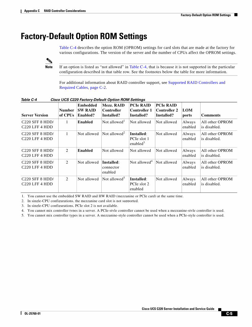
C-5Cisco UCS C220 Server Installation and Service Guide
OL-25760-01
Appendix C RAID Controller ConsiderationsFactory-Default Option ROM Settings
Factory-Default Option ROM SettingsTable C-4 describes the option ROM (OPROM) settings for card slots that are made at the factory for various configurations. The version of the server and the number of CPUs affect the OPROM settings.
Note If an option is listed as “not allowed” in Table C-4, that is because it is not supported in the particular configuration described in that table row. See the footnotes below the table for more information.
For additional information about RAID controller support, see Supported RAID Controllers and Required Cables, page C-2.
Table C-4 Cisco UCS C220 Factory-Default Option ROM Settings
Server VersionNumber of CPUs
Embedded SW RAID Enabled?
Mezz. RAID Controller Installed?
PCIe RAID Controller 1 Installed?
PCIe RAID Controller 2 Installed?
LOM ports Comments
C220 SFF 8 HDD/ C220 LFF 4 HDD
1 Enabled Not allowed1
1. You cannot use the embedded SW RAID and HW RAID (mezzanine or PCIe card) at the same time.
Not allowed Not allowed Always enabled
All other OPROM is disabled.
C220 SFF 8 HDD/ C220 LFF 4 HDD
1 Not allowed Not allowed2
2. In single-CPU configurations, the mezzanine card slot is not supported.
Installed: PCIe slot 1 enabled3
3. In single-CPU configurations, PCIe slot 2 is not available.
Not allowed Always enabled
All other OPROM is disabled.
C220 SFF 8 HDD/ C220 LFF 4 HDD
2 Enabled Not allowed Not allowed Not allowed Always enabled
All other OPROM is disabled.
C220 SFF 8 HDD/ C220 LFF 4 HDD
2 Not allowed Installed: connector enabled
Not allowed4
4. You cannot mix controller types in a server. A PCIe-style controller cannot be used when a mezzanine-style controller is used.
Not allowed Always enabled
All other OPROM is disabled.
C220 SFF 8 HDD/ C220 LFF 4 HDD
2 Not allowed Not allowed5
5. You cannot mix controller types in a server. A mezzanine-style controller cannot be used when a PCIe-style controller is used.
Installed: PCIe slot 2 enabled
Not allowed Always enabled
All other OPROM is disabled.
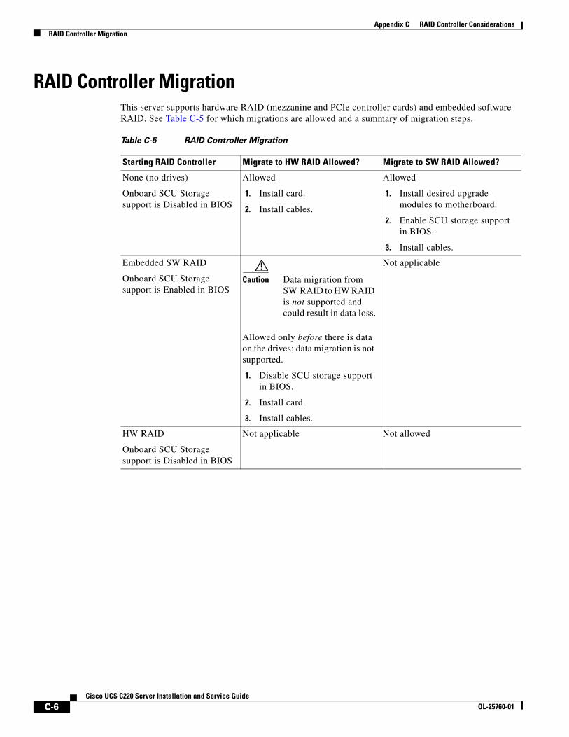
C-6Cisco UCS C220 Server Installation and Service Guide
OL-25760-01
Appendix C RAID Controller ConsiderationsRAID Controller Migration
RAID Controller MigrationThis server supports hardware RAID (mezzanine and PCIe controller cards) and embedded software RAID. See Table C-5 for which migrations are allowed and a summary of migration steps.
Table C-5 RAID Controller Migration
Starting RAID Controller Migrate to HW RAID Allowed? Migrate to SW RAID Allowed?
None (no drives)
Onboard SCU Storage support is Disabled in BIOS
Allowed
1. Install card.
2. Install cables.
Allowed
1. Install desired upgrade modules to motherboard.
2. Enable SCU storage support in BIOS.
3. Install cables.
Embedded SW RAID
Onboard SCU Storage support is Enabled in BIOS
Caution Data migration from SW RAID to HW RAID is not supported and could result in data loss.
Allowed only before there is data on the drives; data migration is not supported.
1. Disable SCU storage support in BIOS.
2. Install card.
3. Install cables.
Not applicable
HW RAID
Onboard SCU Storage support is Disabled in BIOS
Not applicable Not allowed
C-7Cisco UCS C220 Server Installation and Service Guide
OL-25760-01
Appendix C RAID Controller ConsiderationsEmbedded MegaRAID Controller
Embedded MegaRAID Controller
Note VMware ESX/ESXi or any other virtualized environments are not supported for use with the embedded MegaRAID controller. Hypervisors such as Hyper-V, Xen, or KVM are also not supported for use with the embedded MegaRAID controller.
This server includes the option for an embedded MegaRAID controller with two mini-SAS connectors on the motherboard.
• The default setting for this embedded controller is SAS RAID 0, 1, and 10 support for up to four SATA drives.
• You can upgrade this to support to SAS RAID 0, 1, and 10 support for up to eight SAS drives by installing a Storage Controller Unit (SCU) upgrade ROM chip on the motherboard. See Installing a SCU Upgrade ROM Module For Embedded RAID SAS Support, page C-9.
• You can further upgrade this support by adding SAS RAID 5 support with an optional software key. See Installing a Software RAID Key Module for Embedded RAID 5 Support, page C-10.
• When you order the server with this controller, the controller is enabled in the BIOS. Instructions for enabling the controller are included for the case in which a server is reset to defaults (Disabled). See Enabling the Embedded RAID Controller in the BIOS, page C-10.
Note You cannot downgrade from using a RAID controller card to using the embedded controller (see RAID Controller Migration, page C-6). Instructions for installing upgrade modules and enabling the embedded controller in the BIOS are included here for those upgrading a server with no RAID controller or drives.
Caution Data migration from SW RAID (embedded RAID) to HW RAID (a controller card) is not supported and could result in data loss. Migrations from SW RAID to HW RAID are supported only before there is data on the drives, or the case in which there are no drives in the server (see RAID Controller Migration, page C-6).
• You can migrate from using the embedded controller to using a RAID card only before there is data on the drives. In this case, you must disable the embedded controller. See Disabling the Embedded RAID Controller in the BIOS, page C-11.
• The required drivers for this controller are already installed and ready to use with the LSI SWRAID Configuration Utility. However, if you will use this controller with Windows or Linux, you must download and install additional drivers for those operating systems. See Installing LSI MegaSR Drivers For Windows and Linux, page C-11.
This section contains the following topics:
• Notes on Supported Embedded MegaRAID Levels, page C-8
• Installing a SCU Upgrade ROM Module For Embedded RAID SAS Support, page C-9
• Installing a Software RAID Key Module for Embedded RAID 5 Support, page C-10
• Enabling the Embedded RAID Controller in the BIOS, page C-10
• Disabling the Embedded RAID Controller in the BIOS, page C-11
• Launching the LSI Embedded RAID Configuration Utility, page C-11
• Installing LSI MegaSR Drivers For Windows and Linux, page C-11
C-8Cisco UCS C220 Server Installation and Service Guide
OL-25760-01
Appendix C RAID Controller ConsiderationsEmbedded MegaRAID Controller
Notes on Supported Embedded MegaRAID LevelsThe following RAID levels are supported by the embedded MegaRAID controller.
• RAID 0—You can configure a RAID 0 virtual drive (VD) using one or more physical drives (PDs). This level supports up to eight VDs and PDs.
• RAID 1—A RAID 1 VD is configured from only two PDs. This level supports up to eight PDs (four RAID arrays) and eight VDs.
• RAID 5—You can configure a RAID 5 VD using three or more PDs. This level supports up to eight PDs and eight VDs.
• RAID 10—This is a spanned VD; that is, RAID 0 is implemented on two or more RAID 1 VDs. This level supports up to eight PDs (two to four RAID 1 volumes spanned) and one VD.
Note None of these RAID levels require drives of the same size. The smallest drive in the array determines the size of the VD.
Note An array can be divided into multiple VDs of the same RAID level, except when using RAID 10. Mixed arrays are not permitted. For example, you cannot configure a three-drive array into RAID 0 and RAID 5 VDs. Unlike RAID 0, 1, and 5, you cannot create multiple RAID 10 VDs from the same array. A single RAID 10 VD uses up the entire array.
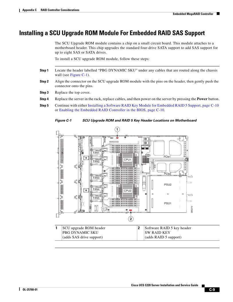
C-9Cisco UCS C220 Server Installation and Service Guide
OL-25760-01
Appendix C RAID Controller ConsiderationsEmbedded MegaRAID Controller
Installing a SCU Upgrade ROM Module For Embedded RAID SAS SupportThe SCU Upgrade ROM module contains a chip on a small circuit board. This module attaches to a motherboard header. This chip upgrades the standard four-drive SATA support to add SAS support for up to eight SAS or SATA drives.
To install a SCU upgrade ROM module, follow these steps:
Step 1 Locate the header labelled “PBG DYNAMIC SKU” under any cables that are routed along the chassis wall (see Figure C-1).
Step 2 Align the connector on the SCU upgrade ROM module with the pins on the header, then gently push the connector onto the pins.
Step 3 Replace the top cover.
Step 4 Replace the server in the rack, replace cables, and then power on the server by pressing the Power button.
Step 5 Continue with either Installing a Software RAID Key Module for Embedded RAID 5 Support, page C-10 or Enabling the Embedded RAID Controller in the BIOS, page C-10.
Figure C-1 SCU Upgrade ROM and RAID 5 Key Header Locations on Motherboard
1 SCU upgrade ROM headerPBG DYNAMIC SKU(adds SAS drive support)
2 Software RAID 5 key headerSW RAID KEY(adds RAID 5 support)
FAN1
FAN2
FAN3
FAN4FAN4
FAN5
PSU2
PCIe1
PCIe2
PSU1
CPU1
CPU2285273
1
2
C-10Cisco UCS C220 Server Installation and Service Guide
OL-25760-01
Appendix C RAID Controller ConsiderationsEmbedded MegaRAID Controller
Installing a Software RAID Key Module for Embedded RAID 5 SupportThe software RAID key module contains a chip on a small circuit board. This module attaches to a motherboard header. This chip upgrades SAS support to add RAID 5 support (RAID 0, 1, 5, and 10 for up to eight SAS or SATA drives).
Note You must have the SCU upgrade ROM module installed before you can use this module.
To install a RAID 5 software key module, follow these steps:
Step 1 Locate the header that is labeled “SW RAID KEY” (see Figure C-1).
Step 2 Install the RAID 5 software key module onto the pins of the header.
Step 3 Replace the top cover.
Step 4 Replace the server in the rack, replace cables, and then power on the server by pressing the Power button.
Step 5 Continue with Enabling the Embedded RAID Controller in the BIOS, page C-10.
Enabling the Embedded RAID Controller in the BIOSWhen you order the server with this controller, the controller is enabled in the BIOS at the factory.
Note The default setting in the BIOS for the embedded controller is Disabled. When you order the server with the embedded controller, the BIOS setting is Enabled at the factory. However, if a server is reset to defaults, this BIOS setting is reverted to Disabled. Use the procedure below to re-enable the embedded controller.
Use the following procedure to enable the LSI MegaSR drivers.
Step 1 Boot the server and press F2 when prompted to enter the BIOS Setup utility.
Step 2 Select the Advanced tab, then South Bridge.
Step 3 Set Onboard SCU Storage Support to Enabled.
Step 4 Press F10 to save your changes and exit the utility.
C-11Cisco UCS C220 Server Installation and Service Guide
OL-25760-01
Appendix C RAID Controller ConsiderationsEmbedded MegaRAID Controller
Disabling the Embedded RAID Controller in the BIOS
Caution Data migration from SW RAID to HW RAID is not supported and could result in data loss. Migrations from SW RAID to HW RAID are supported only before there is data on the drives, or the case in which there are no drives in the server.
If you migrate from using this embedded controller to a RAID controller card, you must disable the embedded controller in the BIOS (see caution above).
Use the following procedure to disable the LSI MegaSR drivers.
Step 1 Boot the server and press F2 when prompted to enter the BIOS Setup utility.
Step 2 Select the Advanced tab, then South Bridge.
Step 3 Set Onboard SCU Storage Support to Disabled.
Step 4 Press F10 to save your changes and exit the utility.
Launching the LSI Embedded RAID Configuration UtilityLaunch the utility by pressing Ctrl+M when you see the prompt during system boot.
For more information about using the Embedded MegaRAID software to configure your disk arrays, see the LSI Embedded MegaRAID Software User Guide.
Installing LSI MegaSR Drivers For Windows and Linux
Note The required drivers for this controller are already installed and ready to use with the LSI SWRAID Configuration Utility. However, if you will use this controller with Windows or Linux, you must download and install additional drivers for those operating systems.
This section explains how to install the LSI MegaSR drivers for the following supported operating systems:
• Microsoft Windows Server
• Red Hat Enterprise Linux (RHEL)
• SuSE Linux Enterprise Server (SLES)
For the specific supported OS versions, see the Hardware and Software Interoperability Matrix for your server release.
This section contains the following topics:
• Downloading the LSI MegaSR Drivers, page C-12
• Microsoft Windows Driver Installation, page C-12
• Linux Driver Installation, page C-14
C-12Cisco UCS C220 Server Installation and Service Guide
OL-25760-01
Appendix C RAID Controller ConsiderationsEmbedded MegaRAID Controller
Downloading the LSI MegaSR Drivers
The MegaSR drivers are included in the C-series driver ISO for your server and OS. Download the drivers from Cisco.com:
Step 1 Find the drivers ISO file download for your server online and download it to a temporary location on your workstation:
a. See the following URL: http://www.cisco.com/cisco/software/navigator.html
b. Click Unified Computing and Servers in the middle column.
c. Click Cisco UCS C-Series Rack-Mount Standalone Server Software in the right-hand column.
d. Click your model of server in the right-hand column.
e. Click Unified Computing System (UCS) Drivers.
f. Click the release number that you are downloading.
g. Click Download to download the drivers ISO file.
h. Verify the information on the next page, then click Proceed With Download.
i. Continue through the subsequent screens to accept the license agreement and then browse to a location where you want to save the drivers ISO file.
Microsoft Windows Driver Installation
This section explains the steps to install the LSI MegaSR driver in a Windows installation.
This section contains the following topics:
• Windows Server 2008R2 Driver Installation, page C-12
• Updating the Windows Driver, page C-13
• Linux Driver Installation, page C-14
Windows Server 2008R2 Driver Installation
Perform the following steps to install the LSI MegaSR device driver in a new Windows Server 2008R2 operating system. The Windows operating system automatically adds the driver to the registry and copies the driver to the appropriate directory.
Step 1 Create a RAID drive group using the LSI SWRAID Configuration utility before you install this driver for Windows. Launch this utility by pressing Ctrl+M when LSI SWRAID is shown during BIOS post.
Step 2 Download the Cisco UCS C-Series drivers ISO, as described in Downloading the LSI MegaSR Drivers, page C-12.
Step 3 Prepare the drivers on a USB thumb drive:
a. Burn the ISO image to a disc.
b. Browse the contents of the drivers folders to the location of the embedded MegaRAID drivers:
/<OS>/Storage/Intel/C600/
c. Expand the Zip file, which contains the folder with the MegaSR driver files.
d. Copy the expanded folder to a USB thumb drive.
C-13Cisco UCS C220 Server Installation and Service Guide
OL-25760-01
Appendix C RAID Controller ConsiderationsEmbedded MegaRAID Controller
Step 4 Start the Windows driver installation using one of the following methods:
• To install from local media: Connect an external USB DVD drive to the server and then insert the first Windows install disc into the drive. Skip to Step 6.
• To install from remote ISO: Log in to the server’s CIMC interface and continue with the next step.
Step 5 Launch a Virtual KVM console window and select the Virtual Media tab.
a. Click Add Image and browse to select your remote Windows installation ISO file.
b. Select the check box in the Mapped column for the media that you just added, then wait for mapping to complete.
Step 6 Power cycle the server.
Step 7 Press F6 when you see the F6 prompt during bootup. The Boot Menu window opens.
Step 8 On the Boot Manager window, select the physical disc or virtual DVD and press Enter. The Windows installation begins when the image is booted.
Step 9 Press Enter when you see the prompt, “Press any key to boot from CD.”
Step 10 Observe the Windows installation process and respond to prompts in the wizard as required for your preferences and company standards.
Step 11 When Windows prompts you with “Where do you want to install Windows,” install the drivers for embedded MegaRAID:
a. Click Load Driver. You are prompted by a Load Driver dialog to select the driver to be installed.
b. Connect the USB thumb drive that you prepared in Step 3 to the target server.
c. On the Windows Load Driver dialog that you opened in Step a, click Browse.
d. Use the dialog to browse to the location of the drivers folder on the USB thumb drive, and click OK.
Windows loads the drivers from the folder and when finished, the driver is listed under the prompt, “Select the driver to be installed.”
e. Click Next to install the drivers.
Updating the Windows Driver
Perform the following steps to update the LSI MegaSR driver for Windows or to install this driver on an existing system booted from a standard IDE drive.
Step 1 Click Start, point to Settings, and then click Control Panel.
Step 2 Double-click System, click the Hardware tab, and then click Device Manager. Device Manager starts.
Step 3 In Device Manager, double-click SCSI and RAID Controllers, right-click the device for which you are installing the driver, and then click Properties.
Step 4 On the Driver tab, click Update Driver to open the Update Device Driver wizard, and then follow the wizard instructions to update the driver.
C-14Cisco UCS C220 Server Installation and Service Guide
OL-25760-01
Appendix C RAID Controller ConsiderationsEmbedded MegaRAID Controller
Linux Driver Installation
This section explains the steps to install the embedded MegaRAID device driver in a Red Hat Enterprise Linux installation or a SuSE Linux Enterprise Server installation.
This section contains the following topics:
• Obtaining the Driver Image File, page C-14
• Preparing Physical Installation Diskettes For Linux, page C-14
• Installing the Red Hat Linux Driver, page C-16
• Installing the SUSE Linux Enterprise Server Driver, page C-17
Obtaining the Driver Image File
See Downloading the LSI MegaSR Drivers, page C-12 for instructions on obtaining the drivers. The Linux driver is offered in the form of dud-[driver version].img, which is the boot image for the embedded MegaRAID stack.
Note The LSI MegaSR drivers that Cisco provides for Red Hat Linux and SUSE Linux are for the original GA versions of those distributions. The drivers do not support updates to those OS kernels.
Preparing Physical Installation Diskettes For Linux
This section describes how to prepare physical Linux installation diskettes from the driver image files, using either the Windows operating system or the Linux operating system.
Note Alternatively, you can mount the dud.img file as a virtual floppy disk, as described in the installation procedures.
Preparing Physical Installation Diskettes With the Windows Operating System:
Under Windows, you can use the RaWrite floppy image-writer utility to create disk images from image files. Perform the following steps to build installation diskettes.
Step 1 Download the Cisco UCS C-Series drivers ISO, as described in Downloading the LSI MegaSR Drivers, page C-12 and save it to your Windows system that has a diskette drive.
Step 2 Extract the dud.img file:
a. Burn the ISO image to a disc.
b. Browse the contents of the drivers folders to the location of the embedded MegaRAID drivers:
/<OS>/Storage/Intel/C600/
c. Expand the Zip file, which contains the folder with the driver files.
Step 3 Copy the driver update disk image dud-[driver version].img and your file raw write.exe to a directory.
Note RaWrite is not included in the driver package.
Step 4 If necessary, use this command to change the file name of the driver update disk to a name with fewer than eight characters: copy dud-[driver version].img dud.img
C-15Cisco UCS C220 Server Installation and Service Guide
OL-25760-01
Appendix C RAID Controller ConsiderationsEmbedded MegaRAID Controller
Step 5 Open the DOS Command Prompt and navigate to the directory where raw write.exe is located.
Step 6 Type the following command to create the installation diskette: raw write
Step 7 Press Enter.
You are prompted to enter the name of the boot image file.
Step 8 Type the following: dud.img
Step 9 Press Enter.
You are prompted for the target diskette.
Step 10 Insert a floppy diskette into the floppy drive and type: A:
Step 11 Press Enter.
Step 12 Press Enter again to start copying the file to the diskette.
Step 13 After the command prompt returns and the floppy disk drive LED goes out, remove the diskette.
Step 14 Label the diskette with the image name.
Preparing Installation Disks With a Linux Operating System:
Under Red Hat Linux and SuSE Linux, you can use a driver diskette utility to create disk images from image files. Perform the following steps to create the driver update disk:
Step 1 Download the Cisco UCS C-Series drivers ISO, as described in Downloading the LSI MegaSR Drivers, page C-12 and save it to your Linux system that has a diskette drive.
Step 2 Extract the dud.img file:
a. Burn the ISO image to a disc.
b. Browse the contents of the drivers folders to the location of the embedded MegaRAID drivers:
/<OS>/Storage/Intel/C600/
c. Expand the Zip file, which contains the folder with the driver files.
Step 3 Copy the driver update disk image dud-[driver version].img to your Linux system.
Step 4 Insert a blank floppy diskette into the floppy drive.
Step 5 Confirm that the files are in the selected directory.
Step 6 Create the driver update diskette using the following command:
dd if=dud-[driver version].img of=/dev/fd0
Step 7 After the command prompt returns and the floppy disk drive LED goes out, remove the diskette.
Step 8 Label the diskette with the image name.
C-16Cisco UCS C220 Server Installation and Service Guide
OL-25760-01
Appendix C RAID Controller ConsiderationsEmbedded MegaRAID Controller
Installing the Red Hat Linux Driver
For the specific supported OS versions, see the Hardware and Software Interoperability Matrix for your server release.
This section describes the fresh installation of the Red Hat Enterprise Linux device driver on systems with the embedded MegaRAID stack.
Step 1 Create a RAID drive group using the LSI SWRAID Configuration utility before you install this driver for the OS. Launch this utility by pressing Ctrl+M when LSI SWRAID is shown during BIOS post.
Step 2 Prepare the dud.img file using one of the following methods:
• To install from a physical diskette: Use one of the procedures in Preparing Physical Installation Diskettes For Linux, page C-14. Then return to Step 4 of this procedure.
• To install from a virtual floppy disk: Download and save the Cisco UCS C-Series drivers ISO, as described in Downloading the LSI MegaSR Drivers, page C-12. Then continue with the next step.
Step 3 Extract the dud.img file:
a. Burn the ISO image to a disc.
b. Browse the contents of the drivers folders to the location of the embedded MegaRAID drivers:
/<OS>/Storage/Intel/C600/
c. Copy the dud-<driver version>.img file to a temporary location on your workstation.
Step 4 Start the Linux driver installation using one of the following methods:
• To install from local media: Connect an external USB DVD drive to the server and then insert the first RHEL install disc into the drive. Then continue with Step 6.
• To install from remote ISO: Log in to the server’s CIMC interface. Then continue with the next step.
Step 5 Launch a Virtual KVM console window and select the Virtual Media tab.
a. Click Add Image and browse to select your remote RHEL installation ISO file.
b. Click Add Image again and browse to select your dud.img file.
c. Select the check boxes in the Mapped column for the media that you just added, then wait for mapping to complete.
Step 6 Power cycle the server.
Step 7 Press F6 when you see the F6 prompt during bootup. The Boot Menu window opens.
Step 8 On the Boot Manager window, select the physical disc or virtual DVD and press Enter.
The RHEL installation begins when the image is booted.
Step 9 Type one of the following commands at the boot prompt:
• For RHEL 5.x (32- and 64-bit), type: Linux dd blacklist=isci blacklist=ahci noprobe=<atadrive number>
• For RHEL 6.x (32- and 64-bit), type: Linux dd blacklist=isci blacklist=ahci nodmraid noprobe=<atadrive number>
C-17Cisco UCS C220 Server Installation and Service Guide
OL-25760-01
Appendix C RAID Controller ConsiderationsEmbedded MegaRAID Controller
Note The noprobe values depend on the number of drives. For example, to install RHEL 5.7 on a RAID 5 configuration with three drives, enter: Linux dd blacklist=isci blacklist=ahci noprobe=ata1 noprobe=ata2 noprobe=ata3
Step 10 Press Enter.
The prompt asks whether you have a driver disk.
Step 11 Use the arrow key to select Yes, and then press Enter.
Step 12 Select fd0 to indicate that you have a floppy diskette with the driver on it.
Step 13 Do one of the following actions:
• If you prepared the IMG file on a physical diskette in Step 2: Connect an external USB diskette drive to the target server and then insert the diskette in the A:/ drive and press Enter.
• If you mapped the IMG file as a virtual floppy in Step 5: Select the location of the virtual floppy.
The installer locates and loads the driver for your device. The following message appears:
Loading megasr driver...
Step 14 Follow the Red Hat Linux installation procedure to complete the installation.
Step 15 Reboot the system.
Installing the SUSE Linux Enterprise Server Driver
For the specific supported OS versions, see the Hardware and Software Interoperability Matrix for your server release.
This section describes the installation of the SuSE Linux Enterprise Server driver on a system with the embedded MegaRAID stack.
Us e the following procedure to install the SLES drivers.
Step 1 Create a RAID drive group using the LSI SWRAID Configuration utility before you install this driver for the OS. Launch this utility by pressing Ctrl+M when LSI SWRAID is shown during BIOS post.
Step 2 Prepare the dud.img file using one of the following methods:
• To install from a physical diskette: Use one of the procedures in Preparing Physical Installation Diskettes For Linux, page C-14. Then return to Step 4 of this procedure.
• To install from a virtual floppy disk: Download and save the Cisco UCS C-Series drivers ISO, as described in Downloading the LSI MegaSR Drivers, page C-12. Then continue with the next step.
Step 3 Extract the dud.img file:
a. Burn the ISO image to a disc.
b. Browse the contents of the drivers folders to the location of the embedded MegaRAID drivers:
/<OS>/Storage/Intel/C600/
c. Copy the dud-<driver version>.img file to a temporary location on your workstation.
Step 4 Start the Linux driver installation using one of the following methods:
C-18Cisco UCS C220 Server Installation and Service Guide
OL-25760-01
Appendix C RAID Controller ConsiderationsEmbedded MegaRAID Controller
• To install from local media: Connect an external USB DVD drive to the server and then insert the first RHEL install disc into the drive. Skip to Step 6.
• To install from remote ISO: Log in to the server’s CIMC interface and continue with the next step.
Step 5 Launch a Virtual KVM console window and select the Virtual Media tab.
a. Click Add Image and browse to select your remote RHEL installation ISO file.
b. Click Add Image again and browse to select your dud.img file.
c. Select the check box in the Mapped column for the media that you just added, then wait for mapping to complete.
Step 6 Power cycle the server.
Step 7 Press F6 when you see the F6 prompt during bootup. The Boot Menu window opens.
Step 8 On the Boot Manager window, select the physical disc or virtual DVD and press Enter. The SLES installation begins when the image is booted.
Step 9 When the first SLES screen appears, select Installation on the menu.
Step 10 Type one of the following in the Boot Options field:
• For SLES 11 and SLES 11 SP1 (32- and 64-bit), type: brokenmodules=ahci
• For SLES 11 SP2 (32-and 64-bit), type: brokenmodules=ahci brokenmodules=isci
Step 11 Press F6 for the driver and select Yes.
Step 12 Do one of the following actions:
• If you prepared the IMG file on a physical diskette in Step 2: Connect an external USB diskette drive to the target server and then insert the diskette in the A:/ drive and press Enter.
• If you mapped the IMG file as a virtual floppy in Step 5: Select the location of the virtual floppy.
“Yes” appears under the F6 Driver heading.
Step 13 Press Enter to select Installation.
Step 14 Press OK.
The following message appears: LSI Soft RAID Driver Updates added.
Step 15 At the menu, select the driver update medium and press the Back button.
Step 16 Continue and complete the installation process by following the prompts.
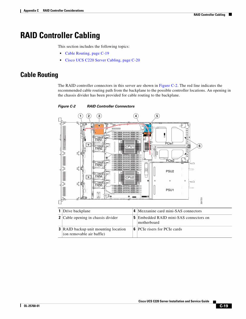
C-19Cisco UCS C220 Server Installation and Service Guide
OL-25760-01
Appendix C RAID Controller ConsiderationsRAID Controller Cabling
RAID Controller CablingThis section includes the following topics:
• Cable Routing, page C-19
• Cisco UCS C220 Server Cabling, page C-20
Cable RoutingThe RAID controller connectors in this server are shown in Figure C-2. The red line indicates the recommended cable routing path from the backplane to the possible controller locations. An opening in the chassis divider has been provided for cable routing to the backplane.
Figure C-2 RAID Controller Connectors
1 Drive backplane 4 Mezzanine card mini-SAS connectors
2 Cable opening in chassis divider 5 Embedded RAID mini-SAS connectors on motherboard
3 RAID backup unit mounting location (on removable air baffle)
6 PCIe risers for PCIe cards
FAN1
FAN2
FAN3
FAN4FAN4
FAN5
PSU2
PCIe1
PCIe2
PSU1
CPU1
CPU2
SAS1
SAS2
SA
S1
SA
S2
3317
21
6
1 2 543
C-20Cisco UCS C220 Server Installation and Service Guide
OL-25760-01
Appendix C RAID Controller ConsiderationsRAID Controller Cabling
Cisco UCS C220 Server CablingThis section contains the following topics:
• Backplane and Expander Options, page C-20
• SFF 8-Drive Backplane Cabling, page C-20
• LFF 4-Drive Backplane Cabling, page C-22
Backplane and Expander Options
The server is orderable in two different versions, each with one of two different front panel/backplane configurations:
• Cisco UCS C220 (small form-factor (SFF) drives, with 8-drive backplane. Holds up to eight 2.5-inch hard drives or solid state drives.
• Cisco UCS C220 (large form factor (LFF) drives, with 4-drive backplane). Holds up to four 3.5-inch hard drives.
SFF 8-Drive Backplane Cabling
The cable connections required for each type of controller are as follows:
Embedded RAID
This option can control up to eight drives.
The required UCSC-CABLE1 cable kit has two mini-SAS cables. Cable 1 controls drives 1–4 and cable 2 controls drives 5–8.
Step 1 Connect mini-SAS cable 1 from the motherboard connector SAS1 to the drives 1–4 connectors on the backplane.
Step 2 Connect the cable 1 SGPIO connector labeled, “S1” to backplane connector S1.
Step 3 Connect mini-SAS cable 2 from the motherboard connector SAS2 to the drives 5–8 connectors on the backplane.
Step 4 Connect the cable 2 SGPIO connector labeled, “S2” to backplane connector S2.
C-21Cisco UCS C220 Server Installation and Service Guide
OL-25760-01
Appendix C RAID Controller ConsiderationsRAID Controller Cabling
Mezzanine-Style Card
This option can control up to eight drives.
The required UCSC-CABLE1 cable kit has two mini-SAS cables. Cable 1 controls drives 1–4 and cable 2 controls drives 5–8.
Step 1 Connect mini-SAS cable 1 from connector SAS1 on the card to the drives 1–4 connectors on the backplane.
Step 2 Connect the mini-SAS cable 1 SGPIO connector S1 to backplane connector S1.
Step 3 Connect mini-SAS cable 2 from connector SAS2 on the card to the drives 5–8 connectors on the backplane.
Step 4 Connect the mini-SAS cable 2 SGPIO connector S2 to backplane connector S2.
PCIe-Style Card
This option can control up to eight drives.
The required UCSC-CABLE1 cable kit has two mini-SAS cables. Cable 1 controls drives 1–4 and cable 2 controls drives 5–8.
Step 1 Connect mini-SAS cable 1 from connector SAS1 on the card to the drives 1–4 connectors on the backplane.
Step 2 Connect the mini-SAS cable 1 SGPIO connector S1 to backplane connector S1.
Step 3 Connect mini-SAS cable 2 from connector SAS2 on the card to the drives 5–8 connectors on the backplane.
Step 4 Connect the mini-SAS cable 2 SGPIO connector S2 to backplane connector S2.
C-22Cisco UCS C220 Server Installation and Service Guide
OL-25760-01
Appendix C RAID Controller ConsiderationsRAID Controller Cabling
LFF 4-Drive Backplane Cabling
The cable connections required for each type of controller are as follows:
Embedded RAID
This option can control up to four drives.
The required UCSC-CABLE3 cable kit has two mini-SAS cables. Cable 1 controls drives 1–4.
Step 1 Connect mini-SAS cable 1 from the motherboard connector SAS1 to the drives 1–4 connectors on the backplane.
Step 2 Connect the cable 1 SGPIO connector labeled, “S1” to backplane connector S1.
Mezzanine-Style Card
This option can control up to four drives.
The required UCSC-CABLE3 cable kit has two mini-SAS cables. Cable 1 controls drives 1–4.
Step 1 Connect mini-SAS cable 1 from connector SAS1 on the card to the drives 1–4 connectors on the backplane.
Step 2 Connect the mini-SAS cable 1 SGPIO connector S1 to backplane connector S1.
PCIe-Style Card
This option can control up to four drives.
The required UCSC-CABLE3 cable kit has two mini-SAS cables. Cable 1 controls drives 1–4.
Step 1 Connect mini-SAS cable 1 from connector SAS1 on the card to the drives 1–4 connectors on the backplane.
Step 2 Connect the mini-SAS cable 1 SGPIO connector S1 to backplane connector S1.
C-23Cisco UCS C220 Server Installation and Service Guide
OL-25760-01
Appendix C RAID Controller ConsiderationsRestoring RAID Configuration After Replacing a RAID Controller
Restoring RAID Configuration After Replacing a RAID ControllerWhen you replace a RAID controller, the RAID configuration that is stored in the controller is lost. Use the following procedure to restore your RAID configuration to your new RAID controller.
Step 1 Replace your RAID controller. See Replacing a PCIe Card, page 3-35.
Step 2 If this was a full chassis swap, replace all drives into the drive bays, in the same order that they were installed in the old chassis.
Step 3 Reboot the server and watch for the prompt to press F.
Note For newer RAID controllers, you are not prompted to press F. Instead, the RAID configuration is imported automatically. In this case, skip to Step 6.
Step 4 Press F when you see the following on-screen prompt:
Foreign configuration(s) found on adapter.Press any key to continue or ‘C’ load the configuration utility,or ‘F’ to import foreign configuration(s) and continue.
Step 5 Press any key (other than C) to continue when you see the following on-screen prompt:
All of the disks from your previous configuration are gone. If this is an unexpected message, then please power of your system and check your cablesto ensure all disks are present.Press any key to continue, or ‘C’ to load the configuration utility.
Step 6 Watch the subsequent screens for confirmation that your RAID configuration was imported correctly.
• If you see the following message, your configuration was successfully imported. The LSI virtual drive is also listed among the storage devices.
N Virtual Drive(s) found on host adapter.
• If you see the following message, your configuration was not imported. This can happen if you do not press F quickly enough when prompted. In this case, reboot the server and try the import operation again wen you are prompted to press F.
0 Virtual Drive(s) found on host adapter.
For More Information The LSI utilities have help documentation for more information about using the utilities.
For basic information about RAID and for using the utilities for the RAID controller cards that are supported in Cisco servers, see the Cisco UCS Servers RAID Guide.
For more information about using the Embedded MegaRAID software to configure your disk arrays, see the LSI Embedded MegaRAID Software User Guide.
Full LSI documentation is also available:
• LSI MegaRAID SAS Software User’s Guide (for LSI MegaRAID)
http://www.cisco.com/en/US/docs/unified_computing/ucs/3rd-party/lsi/mrsas/userguide/LSI_MR_SAS_SW_UG.pdf
C-24Cisco UCS C220 Server Installation and Service Guide
OL-25760-01
Appendix C RAID Controller ConsiderationsFor More Information
• LSI SAS2 Integrated RAID Solution User Guide (for LSI SAS 2008)
http://www.cisco.com/en/US/docs/unified_computing/ucs/3rd-party/lsi/irsas/userguide/LSI_IR_SAS_UG.pdf
D-1Cisco UCS C220 Server Installation and Service Guide
OL-25760-01
A P P E N D I X DInstallation for Cisco UCS Integration
The Cisco UCS integration instructions have been moved to the integration guides found here:
Cisco UCS C-Series Server Integration with UCS Manager Guides
Refer to the guide that is for the version of Cisco UCS Manager that you are using.
D-2Cisco UCS C220 Server Installation and Service Guide
OL-25760-01
Appendix D Installation for Cisco UCS Integration