Embed Size (px)
Citation preview

Cisco Small Business
SLM Smart Switches
ADMINISTRATION GUIDE

© 2009 Cisco Systems, Inc. All rights reserved. OL-20245-01
CCDE, CCENT, CCSI, Cisco Eos, Cisco HealthPresence, Cisco Ironport, the Cisco logo, Cisco Lumin, Cisco Nexus, Cisco Nurse Connect,Cisco Stackpower, Cisco StadiumVision, Cisco TelePresence, Cisco Unified Computing System, Cisco WebEx, DCE, Flip Channels, Flip forGood, Flip Mino, Flip Video, Flip Video (Design), Flipshare (Design), Flip Ultra, and Welcome to the Human Network are trademarks;Changing the Way We Work, Live, Play, and Learn, Cisco Store, and Flip Gift Card are service marks; and Access Registrar, Aironet,AsyncOS, Bringing the Meeting To You, Catalyst, CCDA, CCDP, CCIE, CCIP, CCNA, CCNP, CCSP, CCVP, Cisco, the Cisco CertifiedInternetwork Expert logo, Cisco IOS, Cisco Press, Cisco Systems, Cisco Systems Capital, the Cisco Systems logo, Cisco Unity, CollaborationWithout Limitation, EtherFast, EtherSwitch, Event Center, Fast Step, Follow Me Browsing, FormShare, GigaDrive, HomeLink, InternetQuotient, IOS, iPhone, iQuick Study, IronPort, the IronPort logo, LightStream, Linksys, MediaTone, MeetingPlace, MeetingPlace ChimeSound, MGX, Networkers, Networking Academy, Network Registrar, PCNow, PIX, PowerPanels, ProConnect, ScriptShare, SenderBase,SMARTnet, Spectrum Expert, StackWise, The Fastest Way to Increase Your Internet Quotient, TransPath, WebEx, and the WebEx logo areregistered trademarks of Cisco Systems, Inc. and/or its affiliates in the United States and certain other countries.
All other trademarks mentioned in this document or website are the property of their respective owners. The use of the word partner does not
imply a partnership relationship between Cisco and any other company. (0907R)

Contents
Contents
Chapter 1: Getting Started 1
Starting the Application 1
The About Window 2
Setup 3
Summary 3
Network Settings 5
Time 7
Chapter 2: Port Management 12
Port Settings 12
Link Aggregation 17
LACP 22
PoE Power Settings 23
Chapter 3: VLAN Management 25
Create VLAN 25
Port Setting 27
Port to VLAN 28
VLAN to Port 30
Chapter 4: Statistics 32
Interface Statistics 32
Chapter 5: Security 36
802.1x Settings 36
Port Security 38
IP Access List 41
Storm Control 42
RADIUS 44
Cisco Small Business SLM Smart Switches Administration Guide 1

Contents
Chapter 6: Quality of Service 46
CoS Settings 47
Queue Settings 49
DSCP Settings 51
Basic Mode 52
Chapter 7: Spanning Tree 54
STP Status 54
Global STP 56
STP Port Settings 58
Chapter 8: Multicast 62
IGMP Snooping 62
Bridge Multicast 64
Bridge Multicast Forward All 66
Chapter 9: Admin 68
User Authentication 68
Static Address 70
Dynamic Address 72
Port Mirroring 74
Save Configuration 75
Firmware Upgrade 77
Reboot 79
Factory Default 80
Logging 81
Memory Logs 82
Flash Logs 83
Defining Bonjour 84
Cisco Small Business SLM Smart Switches Administration Guide 2

Getting StartedStarting the Application 1
Getting Started
Thank you for choosing the Cisco Small Business Series Smart Gigabit Ethernet Switch. The Smart Gigabit Ethernet Switches are cost-effective switching solutions ideal for small businesses, the network edge, or workgroups within larger organizations. These easy-to-install, high speed switches offer many of the same Quality of Service and Security features found in more expensive full Layer 2 managed switches but without their complexity. The Smart Switches offer the following interfaces:
• The SLM2024 and SLM2048 offer twenty four (24) or forty eight (48) Gigabit copper ports, with two (2) shared copper or optical (SFP) uplink interfaces for connecting the switch to the core network.
• The SLM224G, SLM224P, SLM248G, and SLM248P offer twenty four (24) or forty eight (48) 10/100 copper ports, with two (2) shared Gigabit copper or optical (SFP) uplink interfaces for connecting the switch to the core network.
The Smart Switch’s simplified user interface is an intuitive management tool enabling you to quickly utilize the comprehensive feature-set of the switch, resulting in a better optimized network. The user interface is a web based application that uses Microsoft Internet Explorer 6.0 or later, or Firefox 5.0 or later.
Starting the Application
To open the User Interface:
STEP 1 Open a web browser.
NOTE The default IP address is 192.168.1.254. If you have changed the IP address or are using DHCP to assign it, enter the new IP address instead. The computer you use for configuration should be on the same subnet as the Switch.
Cisco Small Business SLM Series Smart Switches Administration Guide 1

Getting StartedStarting the Application 1
STEP 2 Enter the device’s IP address in the address bar and press Enter. The Login window opens:
Login window
When the Login window initially loads, both the Username and Password fields are empty. Enter a Username and Password and click Log In. The default user name is admin. The default password is admin. Passwords are alpha-numeric and case-sensitive.
While the system is verifying the login attempt, the Login Progress Indicator appears. If the login attempt is successful, the Summary page opens.
The About Window
Click About in the top right corner of any window to display the About window. This window displays the device name and version number.
Cisco Small Business SLM Series Smart Switches Administration Guide 2

Getting StartedSetup 1
About
Setup
The Setup configuration options are as follows:
• Summary
• Network Settings
• Time
Summary
The Summary window displays general device information and parameters.
To open the Summary window:
Cisco Small Business SLM Series Smart Switches Administration Guide 3

Getting StartedSetup 1
STEP 1 Click Setup > Summary. The Summary window appears:
Summary
The Summary window contains the following fields:
• System Name — Displays the user-configured name of the system, which is configured in the Network Settings window.
• IP Address — Displays the device IP address.
• Subnet Mask — Displays the configured IP subnet mask.
• DNS Server — Displays the DNS server’s IP address.
• Default Gateway — Displays the device’s Gateway IP address.
• Address Mode — Displays the IP address mode using DHCP or Static. The possible field values are:
- DHCP — Retrieves the IP addresses using DHCP.
- Static — The IP address is statically defined.
• Base MAC Address — Displays the device’s MAC address.
Cisco Small Business SLM Series Smart Switches Administration Guide 4

Getting StartedSetup 1
• Jumbo Frame — Enables Jumbo Frames on the device (packet size of up to 9k is supported). Jumbo Frames enable the transportation of data in fewer frames. This ensures less overhead, lower processing time, and fewer interruptions.
NOTE The Jumbo Frame Setting applies only to SLM2024 and SLM2048 Smart Switches. Other Smart Switches do not support this feature.
The possible field values are:
- Enable — Switch will recognize and forward Jumbo Frames.
- Disable — Switch will not recognize or forward Jumbo Frames.
• Model Name — Displays the device model name.
• Hardware Version — Displays the hardware version number.
• Boot Version — Indicates the system boot version currently running on the device.
• Firmware Version — Displays the firmware / software version.
• System Location — Displays the location where the system is currently running.
• System Contact — Displays the name of the contact person.
• System Up Time — Displays the amount of time that has elapsed since the last device reset. The system time is displayed in the following format: Days, Hours, Minutes and Seconds. For example: 41 days, 2 hours, 22 minutes and 15 seconds.
• Current Time — Displays the current time and date.
Network Settings
The Network Settings window allows you to edit many of the fields on the Summary window where they cannot be edited.
To open the Network Settings window:
Cisco Small Business SLM Series Smart Switches Administration Guide 5

Getting StartedSetup 1
STEP 1 Click Setup > Network Settings. The Network Settings window appears:
Network Settings
The Network Settings window contains the following fields:
• System Name — Defines the user-defined system name.
• System Location — Defines the user-defined system location, for example, 3rd floor.
• System Contact — Defines the user-defined system contact person.
• Base MAC Address — Displays the MAC address.
• Management VLAN — Selects the management VLAN. The default is 1.
• IP Address Mode — Retrieves the IP address mode using DHCP or Static. The possible field values are:
- DHCP — Retrieves the IP addresses using DHCP.
- Static — The IP addresses are statically defined. If Static is selected the IP Address, Subnet Mask, and Default Gateway fields are available.
• IP Address — Defines the system IP address.
Cisco Small Business SLM Series Smart Switches Administration Guide 6

Getting StartedSetup 1
• Subnet Mask — Defines the system IP address mask.
• Default Gateway —Defines the system IP default gateway.
• DNS Server — Defines the DNS server IP address.
STEP 2 Define the relevant fields.
STEP 3 Click Save Settings. The settings are modified, and the device is updated.
Time
The Time window contains fields for defining system time parameters for the local device clock. Daylight Savings Time can be enabled on the device.
The following is a list of Daylight Time start and end times in specific countries:
• Albania — Last weekend of March until the last weekend of October.
• Australia — From the end of October until the end of March.
• Australia - Tasmania — From beginning of October until the end of March.
• Armenia — Last weekend of March until the last weekend of October.
• Austria — Last weekend of March until the last weekend of October.
• Bahamas — From April to October, in conjunction with U.S. summer hours.
• Belarus — Last weekend of March until the last weekend of October.
• Belgium — Last weekend of March until the last weekend of October.
• Brazil — From the 3rd Sunday in October until the 3rd Saturday in March. During the period of Daylight Saving Time, Brazilian clocks go forward one hour in most of the Brazilian southeast.
• Chile — The first Sunday in March or after 9th March. In addition, Easter Island DST starts 9th March and ends the 12th October.
• China — China does not operate Daylight Saving Time.
• Canada — From the first Sunday in April until the last Sunday of October. Daylight Saving Time is usually regulated by provincial and territorial governments. Exceptions may exist in certain municipalities.
• Cuba — From the last Sunday of March to the last Sunday of October.
Cisco Small Business SLM Series Smart Switches Administration Guide 7

Getting StartedSetup 1
• Cyprus — Last weekend of March until the last weekend of October.
• Denmark — Last weekend of March until the last weekend of October.
• Egypt — Last Friday in April until the last Thursday in September.
• Estonia — Last weekend of March until the last weekend of October.
• Finland — Last weekend of March until the last weekend of October.
• France — Last weekend of March until the last weekend of October.
• Germany — Last weekend of March until the last weekend of October.
• Greece — Last weekend of March until the last weekend of October.
• Hungary — Last weekend of March until the last weekend of October.
• India — India does not operate Daylight Saving Time.
• Iran — From 1st Farvardin until the 1st Mehr.
• Iraq — From 1st April until 1st October.
• Ireland — Last weekend of March until the last weekend of October.
• Israel — Varies year-to-year.
• Italy — Last weekend of March until the last weekend of October.
• Japan — Japan does not operate Daylight Saving Time.
• Jordan — Last weekend of March until the last weekend of October.
• Latvia — Last weekend of March until the last weekend of October.
• Lebanon — Last weekend of March until the last weekend of October.
• Lithuania — Last weekend of March until the last weekend of October.
• Moldova — Last weekend of March until the last weekend of October.
• Montenegro — Last weekend of March until the last weekend of October.
• Netherlands — Last weekend of March until the last weekend of October.
• New Zealand — From the first Sunday in October until the first Sunday on or after 15th March.
• Norway — Last weekend of March until the last weekend of October.
• Paraguay — From 6th April until 7th September.
Cisco Small Business SLM Series Smart Switches Administration Guide 8

Getting StartedSetup 1
• Poland — Last weekend of March until the last weekend of October.
• Portugal — Last weekend of March until the last weekend of October.
• Romania — Last weekend of March until the last weekend of October.
• Russia — Last weekend of March until the last weekend of October.
• Serbia — Last weekend of March until the last weekend of October.
• Slovak Republic — Last weekend of March until the last weekend of October.
• South Africa — South Africa does not operate Daylight Saving Time.
• Spain — Last weekend of March until the last weekend of October.
• Sweden — Last weekend of March until the last weekend of October.
• Switzerland — Last weekend of March until the last weekend of October.
• Syria — From 31st March until 30th October.
• Taiwan — Taiwan does not operate Daylight Saving Time.
• Turkey — Last weekend of March until the last weekend of October.
• United Kingdom — Last weekend of March until the last weekend of October.
• United States of America — The US Daylight Saving Time changed in 2007 to start on second Sunday in March and end on first Sunday in November. Please see http://aa.usno.navy.mil/faq/docs/daylight_time.php.
To open the Time window:
STEP 1 Click Setup > Time. The Time window appears.
Cisco Small Business SLM Series Smart Switches Administration Guide 9

Getting StartedSetup 1
Time
The Time window is divided into two configuration areas:
• Local Time
• Daylight Saving
Local Time
The Local Time area contains the following fields:
• Hours — Sets the hours.
• Minutes — Sets the minutes.
• Seconds — Sets the seconds.
• Month — Sets the month.
• Day — Sets the day.
• Year — Sets the year.
• Time Zone — Specifies the difference between Greenwich Mean Time (GMT) and local time. For example, the Time Zone Offset for Paris is GMT +1, while the local time in New York is GMT –5.
Cisco Small Business SLM Series Smart Switches Administration Guide 10

Getting StartedSetup 1
Daylight Saving
The Daylight Saving area contains the following fields:
• Daylight Saving — Enables the Daylight Savings Time (DST) on the device based on the devices location.
• Time Set Offset — Specifies the amount of time for DST that can be set in minutes. The default time is 60 minutes.
STEP 2 Define the relevant fields.
STEP 3 Click Save Settings. The settings are modified, and the device is updated.
Cisco Small Business SLM Series Smart Switches Administration Guide 11

Port ManagementPort Settings 2
Port Management
The Port Management configuration options are as follows:
• Port Settings
• Link Aggregation
• LACP
• PoE Power Setting (in SLM224P and SLM248P only)
Port Settings
You use the Port Settings window to display the speed, duplex mode, and flow control used on specific ports, or use to detect the connection settings used by the attached device. Use the full-duplex mode on ports whenever possible to double the throughput of switch connections. Flow control should also be enabled to control network traffic during periods of congestion and prevent the loss of packets when port buffer thresholds are exceeded. The Switch supports flow control based on the IEEE 802.3x standard.
To open the Port Settings window:
Cisco Small Business SLM Series Smart Switches Administration Guide 12

Port ManagementPort Settings 2
STEP 1 Click Port Management > Port settings. The Port Settings window appears:
Port Settings
The Port Settings window contains the following fields:
• Port — Displays the port number.
• Description — Displays the device port user-defined description.
• Administrative Status — Displays the port admin status. The possible field values are:
- Up — Indicates the port is administratively enabled.
- Down — Indicates the port is currently administratively disabled.
• Link Status — Defines whether the port is currently operational or non-operational. The possible field values are:
- Up — Indicates the port is currently operating.
- Down — Indicates the port is currently not operating.
• Speed — Displays the configured rate for the port. The port type determines what speed setting options are available. Port speeds can only
Cisco Small Business SLM Series Smart Switches Administration Guide 13

Port ManagementPort Settings 2
be configured when auto negotiation is disabled. The possible field values are:
- 10 — Indicates the port is currently configured at 10 Mbps.
- 100 — Indicates the port is currently configured at 100 Mbps.
- 1000 — Indicates the port is currently configured at 1000 Mbps.
• Duplex — Displays the port duplex mode, can be either Full or Half. Full indicates that the interface supports transmission between the device and its link partner in both directions simultaneously. Half indicates that the interface supports transmission between the device and the client in only one direction at a time. The Duplex Mode field is configurable only when auto negotiation is disabled, and the port speed is set to 10M or 100M. The Duplex Mode field cannot be configured on LAGs.
• MDI / MDIX — Displays the Media Dependent Interface (MDI) / Media Dependent Interface with Crossover (MDIX) status on the port. Hubs and switches are deliberately wired the opposite of the way end stations are wired, so that when a hub or switch is connected to an end station, a straight through Ethernet cable can be used, and the pairs are matched up properly. When two hubs or switches are connected to each other, or two end stations are connected to each other, a crossover cable is used to ensure that the correct pairs are connected. The possible field values are:
- MDIX — Use for hubs and switches.
- MDI — Use for end stations.
• Flow Control — Displays the flow control status on the port. Operates when the port is in full duplex mode.
• Port Type — Displays the port type. The possible field values are:
- Copper — Indicates the port has a copper port connection and displays the copper speed.
- Fiber — Indicates the port has a fiber optic port connection.
• LAG — Indicates in which LAG the port is a member.
The Detail button displays the Port Configuration window.
Cisco Small Business SLM Series Smart Switches Administration Guide 14

Port ManagementPort Settings 2
Port Configuration
• The Port Configuration window includes the following fields:
• Port — Displays the port number.
• Description — Defines the device port user-defined description.
• Port Type — Displays the port type. The possible field values are:
- Copper — Indicates the port has a copper port connection and displays the copper speed.
- Fiber — Indicates the port has a fiber optic port connection. Both port types run at speeds of 10, 100, and 1000.
• Admin Status — Enables or disables traffic forwarding through the port.
• Current Port Status — Displays the port connection status.
• Reactivate Suspended Port — Reactivates a port if the port has been disabled through the locked port security option.
• Operational Status — Displays whether the port is currently operational or non-operational.
Cisco Small Business SLM Series Smart Switches Administration Guide 15

Port ManagementPort Settings 2
• Admin Speed — The configured rate for the port. The port type determines what speed setting options are available. The auto negotiation should be disabled before setting the speed manually.
• Current Port Speed — Displays the current port speed.
• Admin Duplex — The port duplex mode. Full indicates that the interface supports transmission between the device and the client configured in both directions simultaneously. Half indicates that the interface supports transmission between the device and the client in only one direction at a time.
• Current Duplex Mode — Displays the port current duplex mode.
• Auto Negotiation — Enables Auto Negotiation on the port. Auto Negotiation is a protocol between two link partners that enables a port to advertise its transmission rate, duplex mode and flow control abilities to its partner.
• Current Auto Negotiation — Displays the Auto Negotiation status on the port.
• Admin Advertisement — Specifies the capabilities to be advertised by the port. The possible field values are:
- Max Capability — Indicates that all port speeds and Duplex mode settings will be advertised and accepted.
- 10 Half — Indicates that the port is advertising a 10 mbps speed and half Duplex mode setting.
- 10 Full — Indicates that the port is advertising a 10 mbps speed and full Duplex mode setting.
- 100 Half — Indicates that the port is advertising a 100 mbps speed and half Duplex mode setting.
- 100 Full — Indicates that the port is advertising a 100 mbps speed and full Duplex mode setting.
- 1000 Full — Indicates that the port is advertising a 1000 mbps speed and full Duplex mode setting.
• Current Advertisement — The port advertises its capabilities to its neighbor port to start the negotiation process. The possible field values are those specified in the Admin Advertisement field.
Cisco Small Business SLM Series Smart Switches Administration Guide 16

Port ManagementLink Aggregation 2
• Neighbor Advertisement — The neighbor port (the port to which the selected interface is connected) advertises its capabilities to the port to start the negotiation process.
• Back Pressure — Enables Back Pressure mode on the port. Back Pressure mode is used with Half Duplex mode to allow ports to prevent the link partner from sending traffic. The Back Pressure mode is configured for ports currently in the Half Duplex mode.
• Current Back Pressure — Displays the Back Pressure mode on the port.
• Flow Control — Enables or disables flow control or enables the auto negotiation of flow control on the port.
• Current Flow Control — Displays the current Flow Control setting.
• MDI / MDIX — Defines the Media Dependent Interface (MDI) / Media Dependent Interface with Crossover (MDIX) mode on the port. Hubs and switches are deliberately wired opposite the way end stations are wired, so that when a hub or switch is connected to an end station, a straight through Ethernet cable can be used, and the pairs are matched up properly. When two hubs or switches are connected to each other, or two end stations are connected to each other, a crossover cable is used to ensure that the correct pairs are connected. The possible field values are:
- MDIX — Use for hubs and switches.
- Auto — Use to automatically detect the cable type.
- MDI — Use for end stations.
• Current MDI / MDIX — Displays the current MDI / MDIX setting.
• LAG — Indicates the LAG number of which this port is a member, if relevant.
STEP 2 Define the relevant fields.
STEP 3 Click Save Settings. The settings are modified, and the device is updated.
Link Aggregation
Link Aggregated Groups optimize port usage by linking a group of ports together to form a single aggregated group. Link aggregated groups multiply the bandwidth between the devices, increase port flexibility, and provide link redundancy.
Cisco Small Business SLM Series Smart Switches Administration Guide 17

Port ManagementLink Aggregation 2
The Link Aggregation window contains fields for configuring parameters for configured LAGs. LAGs offer a dramatic increase in bandwidth for network segments where bottlenecks exist, as well as providing a fault-tolerant link between two devices. The device supports up to eight ports per LAG, and eight LAGs per system.
To open the Link Aggregation window:
STEP 1 Click Port Management > Link Aggregation. The Link Aggregation window appears.
Link Aggregation
The Link Aggregation window contains the following fields:
• LAG — Displays the LAG ID number.
• Description — Displays the user-defined LAG name.
• Admin Status — Enables or disables traffic forwarding through the selected LAG.
• Type — The port types that make up the LAG. The possible field values are:
- eth100M
- eth1000m
Cisco Small Business SLM Series Smart Switches Administration Guide 18

Port ManagementLink Aggregation 2
• Link Status — Indicates if the LAG is currently linked. The possible field values are:
- Up — Indicates the LAG is currently linked, and is forwarding or receiving traffic.
- Down — Indicates the LAG is not currently linked, and is not forwarding or receiving traffic.
• Speed — Displays the rate for the LAG. The possible field values are:
- 10 — Indicates the port operates at 10 Mbps.
- 100 — Indicates the port operates at 100 Mbps.
- 1000 — Indicates the port operates at 1000 Mbps.
• Duplex — Displays the LAG duplex mode, can be either Full or Half, though LAGs are in most cases FULL. Full indicates that the interface supports transmission between the device and its link partner in both directions simultaneously. Half indicates that the interface supports transmission between the device and the client in only one direction at a time.
• Flow Control — Displays the flow control status of the LAG.
• LAG — Displays the LAG status. The possible field values are:
- Static
- LACP
- Link Not Present
The Detail button displays the Link Aggregation window.
Cisco Small Business SLM Series Smart Switches Administration Guide 19

Port ManagementLink Aggregation 2
Link Aggregation
The Link Aggregation window displays the following fields:
• LAG — Displays the LAG ID number.
• Description — Displays the user-defined LAG name.
• LACP — Enables or disables Link Aggregation Control Protocol (LACP). This box must be checked before the first port is added to the LAG.
• LAG Type — Specifies the type of LAG. The possible field values are:
- eth100M
- eth1000M
• Admin Status — Enables or disables traffic forwarding through the selected LAG.
• Current Status — Indicates if the LAG is currently operating.
• Reactivate Suspended LAG — Reactivates a LAG if the LAG has been disabled. A LAG is suspended if a Lock Port action has been applied on a LAG member.
Cisco Small Business SLM Series Smart Switches Administration Guide 20

Port ManagementLink Aggregation 2
• Operational Status — Defines whether the port is currently operational or non-operational.
• Admin Auto Negotiation — Enables or disables Auto Negotiation on the LAG. Auto-negotiation is a protocol between two link partners that enables a LAG to advertise its transmission rate, duplex mode and flow control (the flow control default is disabled) abilities to its partner.
• Current Auto Negotiation — The current Auto Negotiation setting.
• Admin Advertisement — Specifies the capabilities to be advertised by the LAG. The possible field values are:
- Max Capability — Indicates that all port speeds and Duplex mode settings can be accepted.
- 10 Full — Indicates that the port is advertising a 10 mbps speed and full Duplex mode setting.
- 100 Full — Indicates that the port is advertising a 100 mbps speed and full Duplex mode setting.
- 1000 Full — Indicates that the port is advertising a 1000 mbps speed and full Duplex mode setting.
• Current Advertisement — The port advertises its capabilities to its neighbor port to start the negotiation process. The possible field values are those specified in the Admin Advertisement field.
• Neighbor Advertisement — The neighbor port (the port to which the selected interface is connected) advertises its capabilities to the port to start the negotiation process.
• Admin Speed — The configured speed of the LAG.
• Current LAG Speed — The current speed at which the LAG is operating.
• Admin Flow Control — Enables or disables flow control or enables the auto negotiation of flow control on the LAG.
• Current Flow Control — Displays the current Flow Control setting.
• Select Ports — Select the ports to assign to the LAG.
STEP 2 Define the relevant fields.
STEP 3 Click Save Settings. The settings are modified, and the device is updated.
Cisco Small Business SLM Series Smart Switches Administration Guide 21

Port ManagementLACP 2
LACP
Aggregate ports can be linked into link-aggregation port groups. Each group is comprised of ports with the same speed, set to full-duplex operations.
Aggregated Links can be manually setup or automatically established by enabling Link Aggregation Control Protocol (LACP) on the relevant links.
To open the LACP window:
STEP 1 Click Port Management > LACP. The LACP window appears:
LACP
The LACP window is divided into two configuration areas for configuring LACP LAGs:
• Global Parameter
• Port Priority
The LACP window also displays an LACP Port table.
Cisco Small Business SLM Series Smart Switches Administration Guide 22

Port ManagementPoE Power Settings 2
Global Parameter
The Global Parameter area contains the following field:
• LACP System Priority (1-65535) — Indicates the global LACP priority value. The possible range is 1- 65535. The default value is 1.
Port Priority
The Port Priority area contains the following fields:
• Port — Defines the port number to which timeout and priority values are assigned.
• Port-Priority — Defines the LACP priority value for the port. The field range is 1-65535.
• LACP Timeout — Administrative LACP timeout. The possible field values are:
- Short — Defines a short timeout value.
- Long — Defines a long timeout value. This is the default value.
• Admin Key — A value assigned to an LACP port that enables the port to join a LAG. Only ports with the same Admin Key can join the same LACP LAG. This value is assigned automatically by the system based on port to LAG ID membership.
STEP 2 Define the relevant fields.
STEP 3 Click Save Settings. The settings are modified, and the device is updated.
PoE Power Settings
The PoE Power Settings window allows you to configure the Power over Ethernet (PoE) ports on the Switch.
NOTE This option is available for SLM224P and SLM248P only.
To open the PoE Power Settings window:
Cisco Small Business SLM Series Smart Switches Administration Guide 23

Port ManagementPoE Power Settings 2
STEP 1 Click Port Management > PoE Power Settings. The PoE Power Settings window appears:
PoE Power Settings
The PoE Power Settings window displays the currently configured PoE ports and contains the following information:
• Port — Displays the selected port’s number.
• Admin Status — Indicates whether PoE is enabled or disabled on the port.
• Priority — Indicates the PoE port’s priority. The possible values are: Critical, High and Low. The default is Low.
• Power Allocation (milliwatts) — Indicates the actual amount of power the device can supply.
• Power Consumption (milliwatts) — Indicates the actual amount of power actually supplied by the port.
STEP 2 Define the relevant fields.
STEP 3 Click Save Settings. The settings are modified, and the device is updated.
Cisco Small Business SLM Series Smart Switches Administration Guide 24

VLAN ManagementCreate VLAN 3
VLAN Management
A VLAN is a group of ports that can be located anywhere in the network, but communicate as though they belong to the same physical segment.
VLANs help to simplify network management by allowing you to move devices to a new VLAN without having to change any physical connections. VLANs can be easily organized to reflect departmental groups (such as Marketing or R&D), usage groups (such as e-mail), or multicast groups (used for multimedia applications such as video conferencing).
The VLAN Management configuration options are as follows:
• Create VLAN
• Port Setting
• Port to VLAN
• VLAN to Port
Create VLAN
The Create VLAN window provides information and global parameters for configuring and working with VLANs.
To open the Create VLAN window:
Cisco Small Business SLM Series Smart Switches Administration Guide 25

VLAN ManagementCreate VLAN 3
STEP 1 Click VLAN Management > Create VLAN. The Create VLAN window appears:
Create VLAN
The Create VLAN window contains the following fields:
• VLAN ID (2-4094) — Indicates the ID number of the VLAN being configured. Up to 128 VLANs can be created. This field is used to add VLANs one at a time. To add the defined VLAN ID number, press Add.
• VLAN Name — Defines the user-defined VLAN name.
• VLAN Range — Indicates a range of VLANs being configured. To add the defined range of VLAN ID numbers, press Add Range.
• Status — Indicates the VLAN type. The possible field values are:
- Static — Indicates the VLAN is user-defined.
- Default — Indicates the VLAN is the default VLAN.
STEP 2 Define the relevant fields.
STEP 3 Click Save Settings. The settings are modified, and the device is updated.
Cisco Small Business SLM Series Smart Switches Administration Guide 26

VLAN ManagementPort Setting 3
Port Setting
The Port Setting window provides parameters for managing ports that are part of a VLAN. The port default VLAN ID (PVID) is configured on the Port Setting window. All untagged packets arriving at the device are tagged by the port PVID.
To open the Port Setting window:
STEP 1 Click VLAN Management > Port Setting. The Port Setting window appears:
Port Setting
The Port Setting window contains the following fields:
• Port — The port number.
• Acceptable Frame Type — Packet type accepted on the port. Possible values are:
- Tagged— Indicates that only tagged packets are accepted on the port.
- All — Indicates that both tagged and untagged packets are accepted on the port.
Cisco Small Business SLM Series Smart Switches Administration Guide 27

VLAN ManagementPort to VLAN 3
• PVID — Assigns a VLAN ID to untagged packets. The possible values are 1 to 4095. VLAN 4095 is defined as per standard and industry practice as the discard VLAN. Packets classified to the Discard VLAN are dropped.
• Ingress Filtering — Enables or disables Ingress filtering on the port. Ingress filtering discards packets that do not match port ingress rules.
• LAG — Indicates to which LAG this port belongs. If the port is a LAG member, the LAG VLAN settings override the port settings.
STEP 2 Define the relevant fields.
STEP 3 Click Save Settings. The settings are modified, and the device is updated.
Port to VLAN
The Port to VLAN window contains fields for configuring ports to a VLAN. You use the Port to VLAN window to add ports to a VLAN and delete ports from a VLAN. When you add a port to a VLAN, you also specify whether the port is tagged or untagged.
To open the Port to VLAN window:
Cisco Small Business SLM Series Smart Switches Administration Guide 28

VLAN ManagementPort to VLAN 3
STEP 1 Click VLAN Management > Port to VLAN. The Port to VLAN window appears.
Port to VLAN
The Port to VLAN window contains a Port Table for VLAN parameters for each port. Ports are assigned VLAN membership by selecting and configuring the presented configuration options. Ports can have the following configuration options:
• Select VLAN — Indicates the VLAN for which the port membership is configured.
Configuration options are as follows:
• Tagged — Defines the interface as a tagged member of a VLAN. All packets forwarded by the interface are tagged. The packets contain VLAN information.
• Untagged — Packets forwarded by the interface are untagged.
• Excluded — Excludes the interface from the VLAN.
STEP 2 Define the relevant fields.
Cisco Small Business SLM Series Smart Switches Administration Guide 29

VLAN ManagementVLAN to Port 3
STEP 3 Click Save Settings. The settings are modified, and the device is updated.
VLAN to Port
The VLAN to Port window contains fields for configuring VLANs to ports. It displays each port’s VLAN membership information. It is also used to add a port to or delete a port from a VLAN.
To open the VLAN to Port window:
STEP 1 Click VLAN Management > VLAN to Port. The VLAN to Port window appears.
VLAN to Port
The VLAN to Port window contains the following fields:
• Port — Displays the port number.
• Join VLAN — Defines the VLANs to which the interface is joined. Pressing the Join VLAN button displays the Join VLAN to Port window. Select the VLAN to which to add the port and click Add, select the VLANs to be
Cisco Small Business SLM Series Smart Switches Administration Guide 30

VLAN ManagementVLAN to Port 3
tagged or untagged and click Save. To remove the VLAN allocation to the port, select the VLAN already assigned to the port and click Remove.
• VLANs — Displays the VLAN from a drop-down list in which the port is a member and whether the VLAN is tagged or not.
• LAG — Indicates if the port is a member of a LAG. If it is a member of a LAG, it cannot be configured to a VLAN. The LAG to which it belongs can be configured to a VLAN.
STEP 2 Define the relevant fields.
STEP 3 Click Save Settings. The settings are modified, and the device is updated.
Cisco Small Business SLM Series Smart Switches Administration Guide 31

StatisticsInterface Statistics 4
Statistics
The device supports Interface Statistics configuration. The Statistics tab on the Navigation Tree contains the Interface Statistics window, which lets you display statistics for a specified interface.
Interface Statistics
The Interface Statistics window allows you to display statistics for the Ethernet port or LAG that you specify. You can also specify the rate at which the display will be refreshed.
To open the Interface Statistics window:
Cisco Small Business SLM Series Smart Switches Administration Guide 32

StatisticsInterface Statistics 4
STEP 1 Click Statistics > Interface Statistics. The Interface Statistics window appears.
Interface Statistics
The Interface Statistics window is divided into two areas:
• Interface
• Ethernet-like Statistics
Interface
The Interface area displays the statistics for both received and transmitted packets, and contains the following fields:
• Interface — Displays the interface for which Interface statistics are displayed. The possible field values are:
- Port — Defines the specific port for which interface statistics are displayed.
- LAG — Defines the specific LAG for which interface statistics are displayed.
• Refresh Rate — Defines the amount of time that passes before the interface statistics are refreshed. The possible field values are:
Cisco Small Business SLM Series Smart Switches Administration Guide 33

StatisticsInterface Statistics 4
- 15 Sec — Indicates that the Interface statistics are refreshed every 15 seconds.
- 30 Sec — Indicates that the Interface statistics are refreshed every 30 seconds.
- 60 Sec — Indicates that the Interface statistics are refreshed every 60 seconds.
- No Refresh — Indicates that the Interface statistics are not refreshed.
Receive Statistics:
• Total Bytes (Octets) — Displays the number of octets received on the selected interface.
• Unicast Packets — Displays the number of Unicast packets received on the selected interface.
• Multicast Packets — Displays the number of Multicast packets received on the selected interface.
• Broadcast Packets — Displays the number of Broadcast packets received on the selected interface.
• Packets with Errors — Displays the number of error packets received from the selected interface.
Transmit Statistics:
• Total Bytes (Octets) — Displays the number of octets transmitted from the selected interface.
• Unicast Packets — Displays the number of Unicast packets transmitted from the selected interface.
• Multicast Packets — Displays the number of Multicast packets transmitted from the selected interface.
• Broadcast Packets — Displays the number of Broadcast packets transmitted from the selected interface.
Ethernet-like Statistics
The Etherlike Statistics area contains the following fields:
• Frame Check Sequence (FCS) Errors — Displays the number of FCS errors received on the selected interface.
Cisco Small Business SLM Series Smart Switches Administration Guide 34

StatisticsInterface Statistics 4
• Single Collision Frames — Displays the number of single collision frames received on the selected interface.
• Late Collisions — Displays the number of late collision frames received on the selected interface.
• Oversize Packets — Displays the number of oversized packet errors on the selected interface.
• Internal MAC Receive Errors — Number of internal MAC received errors on the selected interface.
• Received Pause Frames — Displays the number of received paused frames on the selected interface.
• Transmitted Pause Frames — Displays the number of paused frames transmitted from the selected interface.
STEP 2 Define the relevant fields.
STEP 3 Click Save Settings. The settings are modified, and the device is updated.
Cisco Small Business SLM Series Smart Switches Administration Guide 35

Security802.1x Settings 5
Security
The Security configuration options are as follows:
• 802.1x Settings
• Port Security
• IP Access List
• Storm Control
• RADIUS
802.1x Settings
Port based authentication enables authenticating system users on a per-port basis via an external server. Only authenticated and approved system users can transmit and receive data. Ports are authenticated via the RADIUS server using the Extensible Authentication Protocol (EAP).
To open the 802.1x Settings window:
Cisco Small Business SLM Series Smart Switches Administration Guide 36

Security802.1x Settings 5
STEP 1 Click Security > 802.1x Settings. The 802.1x Settings window appears.
802.1x Settings
The 802.1x Settings window contains the following fields:
• Enable 802.1x — Enables or disables 802.1x on the device.
• Interface — Indicates the interface to configure the 802.1x settings.
- Port — Indicates port to configure.
• Status Port Control — Specifies the port authorization state. The possible field values are as follows:
- ForceAuthorized — The controlled port state is set to ForceAuthorized (forward traffic).
- ForceUnauthorized — The controlled port state is set to ForceUnauthorized (discard traffic).
- Auto — The controlled port state is set by the system.
• Enable Periodic Reauthentication — Enables periodic reauthentication.
Cisco Small Business SLM Series Smart Switches Administration Guide 37

SecurityPort Security 5
The Setting Timer button opens the Setting Timer window to configure interface timers for 802.1x functionality. The Setting Timer window contains the following fields:
• Port — Indicates the interface.
• Reauthentication Period — Specifies the number of seconds in which the selected port is reauthenticated (Range: 300-4294967295). The field default is 3600 seconds.
• Quiet Period — Specifies the number of seconds that the switch remains in the quiet state following a failed authentication exchange (Range: 0-65535).
• Resending EAP — Specifies the number of seconds that the switch waits for a response to an EAP - request / identity frame, from the supplicant (client), before resending the request.
• Max EAP Requests — The total amount of EAP requests sent. If a response is not received after the defined period, the authentication process is restarted. The field default is 2 retries.
• Supplicant Timeout — Displays the number of seconds that lapses before EAP requests are resent to the supplicant (Range: 1-65535). The field default is 30 seconds.
• Server Timeout — Specifies the number of seconds that lapses before the switch resends a request to the authentication server (Range: 1-65535). The field default is 30 seconds.
• The table displays the basic information per port.
STEP 2 Define the relevant fields.
STEP 3 Click Save Settings. The settings are modified, and the device is updated.
Port Security
Network security can be increased by limiting access on a specific port only to users with specific MAC addresses. The MAC addresses can be dynamically learned or statically configured. Locked port security monitors both received and learned packets that are received on specific ports. Access to the locked port is limited to users with specific MAC addresses. These addresses are either manually defined on the port, or learned on that port up to the point when it is
Cisco Small Business SLM Series Smart Switches Administration Guide 38
SecurityPort Security 5
locked. When a packet is received on a locked port, and the packet source MAC address is not tied to that port (either it was learned on a different port, or it is unknown to the system), the protection mechanism is invoked, and can provide various options.
Locked port security also enables storing a list of MAC addresses in the configuration file. The MAC address list can be restored after the device has been reset.
Disabled ports are activated from the Port Management > Port Settings window, in the Detail section.
To open the Port Security window:
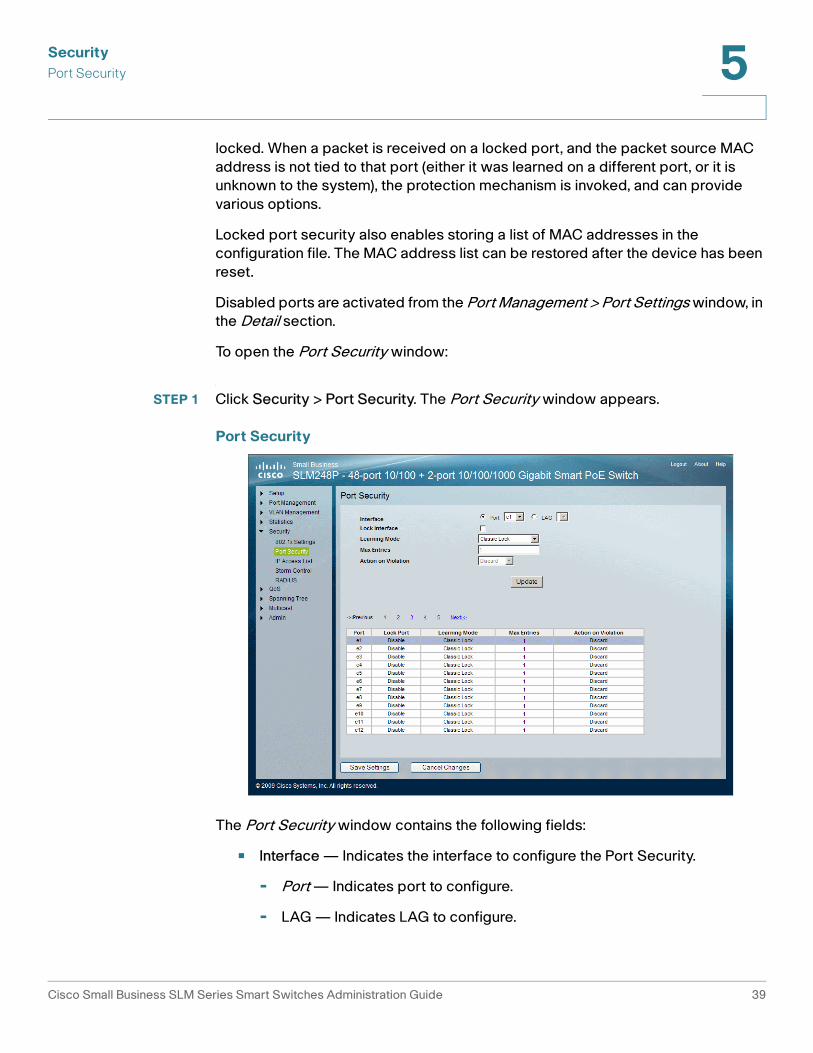
STEP 1 Click Security > Port Security. The Port Security window appears.
Port Security
The Port Security window contains the following fields:
• Interface — Indicates the interface to configure the Port Security.
- Port — Indicates port to configure.
- LAG — Indicates LAG to configure.
Cisco Small Business SLM Series Smart Switches Administration Guide 39

SecurityPort Security 5
• Lock Interface — Configures and indicates the port security status. The possible field values are:
- Unchecked — Indicates that the port is currently unlocked. This is the default value.
- Checked — Indicates that the port is currently locked.
• Learning Mode — Defines the locked port type. The Learning Mode field is enabled only if Locked is not selected in the Lock Interface Status field. The possible field values are:
- Classic Lock — Locks the port using the classic lock mechanism. The port is immediately locked, regardless of the number of addresses that have already been learned. MAC addresses that were already learned on the port are permitted. All other MACs are considered unauthorized.
- Limited Dynamic Lock — The device learns MAC addresses up to the maximum addresses allowed on the port, after which any new MAC is considered unauthorized. Both relearning and aging of MAC addresses are enabled. In order to change the Learning Mode, the Lock Interface must be set to Unlocked. Once the mode is changed, the Lock Interface can be reinstated.
• Max Entries — Specifies the number of MAC addresses that can be learned on the port. The Max Entries field is enabled only if Locked is Not selected in the Lock Interface Status field. In addition, the Limited Dynamic Lock mode is selected. The default is 1.
• Action on Violation — Indicates the action to be applied to unauthorized packets arriving on a locked port. The possible field values are:
- Discard — Discards packets from any unknown source. This is the default value.
- Forward Not on Device — Forwards packets from an unknown source without learning the MAC address.
- Shutdown — Discards packets from any unknown source and shuts down the port. The port remains shut down until reactivated, or until the device is reset.
STEP 2 Define the relevant fields.
STEP 3 Click Save Settings. The settings are modified, and the device is updated.
Cisco Small Business SLM Series Smart Switches Administration Guide 40

SecurityIP Access List 5
IP Access List
The IP Access window enables the user to allow management only from specified IP addresses.
To open the IP Access List window:
STEP 1 Click Security > IP Access List. The IP Access List window appears.
IP Access List
The IP Access List window contains the following fields:
• IP Address — The IP address to be allowed.
• Wildcard Mask — Defines the address wildcard mask. Wildcard masks specify which bits are used and which bits are ignored. A wildcard mask of 0.0.0.0 indicates that no bit is important. A wildcard of 255.255.255.255 indicates that all the bits are important. For example, if the source IP address 149.36.184.198 and the wildcard mask is 255.0.0.0, the first eight bits of the IP address are used, while the last eight bits are ignored.
STEP 2 Define the relevant fields.
Cisco Small Business SLM Series Smart Switches Administration Guide 41

SecurityStorm Control 5
STEP 3 Click Save Settings. The settings are modified, and the device is updated.
Storm Control
Storm Control enables limiting the amount of Multicast and Broadcast frames accepted and forwarded by the device. When frames are forwarded, Broadcast and Multicast frames are flooded to all ports on the relevant VLAN. This occupies bandwidth, and loads all nodes connected on all ports.
A Broadcast Storm is a result of an excessive amount of broadcast messages simultaneously transmitted across a network by a single port. Forwarded message responses are heaped onto the network, straining network resources or causing the network to time out.
Storm Control is enabled by defining the packet type to apply the rate limit and the rate the packets are transmitted. The system measures the incoming Broadcast or Broadcast and Multicast frame rates on each port and discards the frames when the rate exceeds a user-defined rate.
The Storm Control window provides fields for configuring Broadcast and Multicast Storm Control.
To open the Storm Control window:
Cisco Small Business SLM Series Smart Switches Administration Guide 42

SecurityStorm Control 5
STEP 1 Click Security > Storm Control. The Storm Control window appears.
Security > Storm Control
The Storm Control window contains the following fields:
• Interface — Indicates the interface from which storm control is enabled.
- Port — Indicates the port from which storm control is enabled.
• Broadcast Control — Select the checkbox to apply Broadcast Control on the selected interface.
• Mode — Specifies, and allows configuration of the Broadcast mode currently enabled on the device. The possible field values are:
- Multicast & Broadcast — Counts Broadcast and Multicast traffic together.
- Broadcast Only — Counts only Broadcast traffic.
• Rate Threshold — The maximum rate (Kbps) at which Broadcast or Broadcast and Multicast packets are forwarded. The ranges are 70Kbps – 100Mbps for FE ports, and 3.5Mbps – 100Mbps for GE ports. The default value is 3500Kbps.
Cisco Small Business SLM Series Smart Switches Administration Guide 43

SecurityRADIUS 5
The Update button adds the configured Storm Control to the Storm Control Table at the bottom of the window.
STEP 2 Define the relevant fields.
STEP 3 Click Save Settings. The settings are modified, and the device is updated.
RADIUS
Remote Authorization Dial-In User Service (RADIUS) servers provide additional security for networks. RADIUS servers provide a centralized authentication method for 802.1x and web access.
To open the RADIUS window:
STEP 1 Click Security > RADIUS. The RADIUS window appears.
RADIUS
The RADIUS window contains the following fields:
• IP Address — The Authentication Server IP address.
Cisco Small Business SLM Series Smart Switches Administration Guide 44

SecurityRADIUS 5
• Priority — The server priority. The possible values are 0-65535, where 0 is the highest value. The RADIUS Server priority is used to determine the server query order.
• Authentication Port — Identifies the UDP destination port for authentication requests. The authenticated port default is 1812.
• Number of Retries — Defines the number of transmitted requests sent to RADIUS server before a failure occurs. The possible field values are 1 - 10. Three is the default value.
• Timeout for Reply — Defines the amount of the time in seconds the device waits for an answer from the RADIUS server before retrying the query, or switching to the next server. The possible field values are 1 - 30. Three is the default value.
• Dead Time — Defines the amount of time (minutes) that a RADIUS server is bypassed for service requests. The range is 0-2000. The Dead Time default is 0 minutes.
• Key String — Defines the key string used for authenticating and encrypting all RADIUS communications between the device and the RADIUS server. This key must match the encryption key defined on the RADIUS server.
• Source IP Address — Defines the source IP address that is used for communication with RADIUS servers.
• Usage Type — Specifies the RADIUS server authentication type. The default value is Login. The possible field values are:
- Login — Indicates that the RADIUS server is used for authenticating user name and passwords.
- 802.1x — Indicates that the RADIUS server is used for 802.1x authentication.
- All — Indicates that the RADIUS server is used for authenticating user name and passwords, and 802.1x port authentication.
The Add to List button adds the RADIUS configuration to the RADIUS Table at the bottom of the window.
STEP 2 Define the relevant fields.
STEP 3 Click Save Settings. The settings are modified, and the device is updated.
Cisco Small Business SLM Series Smart Switches Administration Guide 45

Quality of Service 6
Quality of Service
Network traffic is usually unpredictable, and the only basic assurance that can be offered is best effort traffic delivery. To overcome this challenge, Quality of Service (QoS) is applied throughout the network. This ensures that network traffic is prioritized according to specified criteria, and that specific traffic receives preferential treatment. QoS in the network optimizes network performance and entails two basic facilities:
• Classifying incoming traffic into handling classes, based on an attribute, including:
- The ingress interface
- Packet content
- A combination of these attributes
• Providing various mechanisms for determining the allocation of network resources to different handling classes, including:
- The assignment of network traffic to a particular hardware queue
- The assignment of internal resources
- Traffic shaping
The terms Class of Service (CoS) and QoS are used in the following context:
• CoS provides varying Layer 2 traffic services. CoS refers to classification of traffic to traffic-classes, which are handled as an aggregate whole, with no per-flow settings. CoS is usually related to the 802.1p service that classifies flows according to their Layer 2 priority, as set in the VLAN header.
• QoS refers to Layer 2 traffic and above. QoS handles per-flow settings, even within a single traffic class.
The QoS facility involves the following elements:
• Traffic Classification — Classifies each incoming packet as belonging to a given traffic class, based on the packet contents.
• Assignment to Hardware Queues — Assigns incoming packets to forwarding queues. Packets are sent to a particular queue for handling as a
Cisco Small Business SLM Series Smart Switches Administration Guide 46

Quality of ServiceCoS Settings 6
function of the traffic class to which they belong, as defined by the classification mechanism.
• Traffic Class-Handling Attributes — Applies QoS / CoS mechanisms to different classes, including:
- Bandwidth Management
The QoS configuration options are as follows:
• CoS Settings
• Queue Settings
• DSCP Setting
• Bandwidth
• Basic Mode
CoS Settings
The CoS Settings window contains fields for globally enabling or disabling QoS, and defining other CoS related settings.
The CoS Settings window has three areas, Global CoS Mode, CoS Queue Settings and CoS Interface Default.
To open the CoS Settings window:
Cisco Small Business SLM Series Smart Switches Administration Guide 47

Quality of ServiceCoS Settings 6
STEP 1 Click QoS > CoS Settings. The CoS Settings window appears.
CoS Settings
The CoS Settings area contains the following fields:
• QoS Mode — Indicates if QoS is globally enabled on the device. The possible values are:
- Disable — Disables QoS on the device.
- Basic — Enables QoS on the device.
• Class of Service — Specifies the CoS priority tag values, where zero is the lowest and 7 is the highest.
• Queue — Defines the traffic forwarding queue to which the CoS priority is mapped. Four traffic priority queues are supported.
• Restore Defaults — Restores the device factory defaults for mapping CoS values to a forwarding queue.
The CoS Default area contains the following fields:
• Interface — Interface to which the CoS configuration applies.
Cisco Small Business SLM Series Smart Switches Administration Guide 48

Quality of ServiceQueue Settings 6
• Default CoS — Determines the default CoS value for incoming packets for which a VLAN tag is not defined. The possible field values are 0-7. The default CoS is 0.
• LAG — LAG to which the port belongs, if relevant. If the port is a member of a LAG, the LAG settings override the port settings.
STEP 2 Define the relevant fields.
STEP 3 Click Save Settings. The settings are modified, and the device is updated.
Queue Settings
The Queue Settings window contains fields for defining the QoS queue forwarding modes.
To open the Queue Settings window:
Cisco Small Business SLM Series Smart Switches Administration Guide 49

Quality of ServiceQueue Settings 6
STEP 1 Click QoS > Queue Settings. The Queue Settings window appears.
Queue Settings
The Queue Settings window contains the following fields:
• Strict Priority — Indicates that traffic scheduling for the selected queue is based strictly on the queue priority. Higher priority queues always receive bandwidth before lower priority queues.
• WRR — Indicates that traffic scheduling for the selected queue is based strictly on the WRR.
NOTE Note: WRR and Strict priority exclude each other and are system wide (to all ports).
• Queue — Displays the queue for which the queue settings are displayed. The possible field range is 1 - 4.
• WRR Weight — Defines the WRR weights of the queues in GE devices. In FE devices, the weights are displayed for reference only.
• % of WRR Bandwidth — Displays the amount of bandwidth assigned to the queue. These values are fixed and are not user defined.
Cisco Small Business SLM Series Smart Switches Administration Guide 50

Quality of ServiceDSCP Settings 6
STEP 2 Define the relevant fields.
STEP 3 Click Save Settings. The settings are modified, and the device is updated.
DSCP Settings
The DSCP Settings window contains fields for classifying DSCP settings to traffic queues. For example, a packet with a DSCP value of 4 can be assigned to queue 2.
To open the DSCP Settings window:
STEP 1 Click QoS > DSCP Settings. The DSCP Settings window appears.
DSCP Settings
The DSCP Settings window contains the following fields:
• DSCP — Displays the incoming packet’s DSCP value.
Cisco Small Business SLM Series Smart Switches Administration Guide 51

Quality of ServiceBasic Mode 6
• Queue — Defines the traffic forwarding queue to which the DSCP priority is mapped. Four traffic priority queues are supported.
STEP 2 Define the relevant fields.
STEP 3 Click Save Settings. The settings are modified, and the device is updated.
Basic Mode
To open the Basic Mode window:
STEP 1 Click QoS > Basic Mode. The Basic Mode window appears.
Basic Mode
The Basic Mode window contains the following fields:
• Trust Mode — Displays the trust mode. The Trust Mode determines whether the CoS (VLAN Priority Tagging) mapping or DSCP mapping determine the packet queue. Possible values are:
Cisco Small Business SLM Series Smart Switches Administration Guide 52

Quality of ServiceBasic Mode 6
- CoS — Sets trust mode to CoS on the device. The CoS mapping determines the packet queue.
- DSCP — Sets trust mode to DSCP on the device. The DSCP mapping determines the packet queue.
STEP 2 Define the relevant fields.
STEP 3 Click Save Settings. The settings are modified, and the device is updated.
Cisco Small Business SLM Series Smart Switches Administration Guide 53

Spanning TreeSTP Status 7
Spanning Tree
Spanning Tree Protocol (STP) provides tree topology for any arrangement of bridges. STP also provides one path between end stations on a network, eliminating loops.
Loops occur when alternate routes exist between hosts. Loops in an extended network can cause bridges to forward traffic indefinitely, resulting in increased traffic and reducing network efficiency.
The device supports the Classic STP Spanning Tree version.
The Spanning Tree configuration options are as follows:
• STP Status
• Global STP
• STP Port Settings
STP Status
The STP Status window describes the STP status on the device.
To open the STP Status window:
STEP 1 Click Spanning Tree > STP Status. The STP Status window appears.
Cisco Small Business SLM Series Smart Switches Administration Guide 54

Spanning TreeSTP Status 7
STP Status
The STP Status window contains the following fields:
• Spanning Tree State — Indicates if STP is enabled on the device. The possible field values are:
- Enabled — Indicates STP is enabled on the device.
- Disabled — Indicates STP is disabled on the device.
• Spanning Tree Mode — Indicates the STP mode by which STP is enabled on the device. The possible field values are:
- STP — Indicates Classic STP is enabled on the device.
• Bridge ID — Indicates the bridge priority and MAC address.
• Designated Root — Identifies the bridge priority and MAC address of the root bridge.
• Root Port — Indicates the port number that offers the lowest cost path from this bridge to the Root Bridge. It is significant when the Bridge is not the Root.
• Root Path Cost — The cost of the path from this bridge to the root.
Cisco Small Business SLM Series Smart Switches Administration Guide 55

Spanning TreeGlobal STP 7
• Root Maximum Age (sec) — Indicates the device Maximum Age Time. The Maximum Age Time indicates the timeout period, in seconds, during which the device times out root information. The default max age is 20 seconds. The range is 6 to 40 seconds.
• Root Hello Time (sec) — Indicates the device Hello Time. The Hello Time indicates the amount of time in seconds a root bridge waits between configuration messages. The default is 2 seconds. The range is 1 to 10 seconds.
• Root Forward Delay (sec) — Indicates the device forward delay time. The Forward Delay Time indicates the amount of time in seconds a bridge remains in a learning state before forwarding packets. The default is 15 seconds. The range is 4 to 30 seconds.
• Topology Changes Counts — Indicates the total amount of STP state changes that have occurred.
• Last Topology Change — Indicates the amount of time that has elapsed since the bridge was initialized or reset, and the last topographic change occurred. The time is displayed in a day hour minute second format, for example, 2 days 5 hours 10 minutes and 4 seconds.
Global STP
The Global STP window contains parameters for enabling and configuring STP on the device.
The Global STP window is divided into two areas, Global STP and Bridge Settings.
To open the Global STP window:
Cisco Small Business SLM Series Smart Switches Administration Guide 56

Spanning TreeGlobal STP 7
STEP 1 Click Spanning Tree > Global STP. The Global STP window appears.
Global STP
The Global STP area contains the following fields:
• Spanning Tree State — Indicates if STP is enabled on the device. The possible field values are:
- Enable — Enables STP on the device.
- Disable — Disables STP on the device.
• BPDU Handling — Determines how BPDU packets are managed when STP is disabled on the port or device. BPDUs are used to transmit spanning tree information. The possible field values are:
- Filtering — Filters BPDU packets when spanning tree is disabled on an interface.
- Flooding — Floods BPDU packets when spanning tree is disabled on an interface. This is the default value.
• Path Cost Default Values — Specifies the method used to assign default path costs to STP ports. The possible field values are:
Cisco Small Business SLM Series Smart Switches Administration Guide 57

Spanning TreeSTP Port Settings 7
- Short — Specifies that the default values are per the short default cost method.
- Long — Specifies that the default values are per the long default cost method.
The Bridge Settings area contains the following fields:
NOTE Note: To set Priority, Hello Time, Max Age and Forward delay, each field must be set individually. After each field is set, save the configuration.
• Priority — Specifies the bridge priority value. When switches or bridges are running STP, each is assigned a priority. After exchanging BPDUs, the device with the lowest priority value becomes the Root Bridge. The default value is 32768. The bridge priority value is provided in increments of 4096. For example, 0, 4096, 8192, 12288, etc. The range is 0 to 65535.
• Hello Time — Specifies the device Hello Time. The Hello Time indicates the amount of time in seconds a bridge waits between configuration messages. The default is 2 seconds. The range is 1 to 10 seconds.
• Max Age — Specifies the device Maximum Age Time. The Maximum Age Time indicates the amount of time in seconds a bridge waits before discarding the old Root information. The default max age is 20 seconds. The range is 6 to 40 seconds.
• Forward Delay — Specifies the device forward delay time. The Forward Delay Time indicates the amount of time in seconds a bridge remains in a learning state before forwarding packets. The default is 15 seconds. The range is 4 to 30 seconds.
STEP 2 Define the relevant fields.
STEP 3 Click Save Settings. The settings are modified, and the device is updated.
STP Port Settings
Network administrators can assign STP settings to specific interfaces using the STP Port Settings window.
Cisco Small Business SLM Series Smart Switches Administration Guide 58

Spanning TreeSTP Port Settings 7
To open the STP Port Settings window:
STEP 1 Click Spanning Tree > STP Port Settings. The STP Port Settings window appears.
STP Port Settings
The STP Port Settings window contains the following fields:
• Interface — Indicates the interface on which STP parameters are configured. The possible field values are:
- Port — Indicates the port on which STP is configured.
- LAG — Indicates the LAG on which STP is configured.
• Enable STP — Indicates if STP is enabled on the port. Select this field to enable STP.
• Port Fast — Indicates if Fast Link is enabled on the port. If Fast Link mode is enabled for a port, the Port State is automatically placed in the Forwarding state when the port link is up. Fast Link optimizes the STP protocol convergence. STP convergence can take 30 seconds in large networks. The possible field values are:
- Enable — Indicates that Fast Link is enabled on the port.
Cisco Small Business SLM Series Smart Switches Administration Guide 59

Spanning TreeSTP Port Settings 7
- Auto — Port Fast mode is enabled a few seconds after the interface becomes active.
- Disable — Indicates that Fast Link is disabled on the port.
• Port State — Displays the current STP state of a port. If enabled, the port state determines what forwarding action is taken on traffic. Possible port states are:
- Disabled — Indicates that STP is currently disabled on the port. The port forwards traffic while learning MAC addresses.
- Blocking — Indicates that the port is currently blocked and cannot forward traffic or learn MAC addresses. Blocking is displayed when STP is enabled.
- Listening — Indicates that the port is in Listening mode. The port cannot forward traffic nor can it learn MAC addresses.
- Learning — Indicates that the port is in Learning mode. The port cannot forward traffic, however it can learn new MAC addresses.
- Forwarding — Indicates that the port is in Forwarding mode. The port can forward traffic and learn new MAC addresses.
• Speed — Indicates the speed at which the port is operating.
• Path Cost — Indicates the port contribution to the root path cost. The path cost is adjusted to a higher or lower value. Ports with a lower cost are less likely to be blocked if STP detects loops.
• Default Path Cost — When checked, returns the port path cost to its default value.
• Priority — Priority value of the port. The priority value influences the port choice when a bridge has two ports connected in a loop. The priority value is between 0 -240. The priority value is provided in increments of 16.
• Designated Bridge ID — Indicates the bridge priority and the MAC Address of the designated bridge.
• Designated Port ID — Indicates the port designated priority and interface.
• Designated Cost — Indicates the path cost of the port to the root bridge participating in the STP topology. Ports with a lower cost are less likely to be blocked if STP detects loops.
• Forward Transitions — Indicates the number of times the port has changed from the Blocking state to Forwarding state.
Cisco Small Business SLM Series Smart Switches Administration Guide 60

Spanning TreeSTP Port Settings 7
STEP 2 Define the relevant fields.
STEP 3 Click Save Settings. The settings are modified, and the device is updated.
Cisco Small Business SLM Series Smart Switches Administration Guide 61

MulticastIGMP Snooping 8
Multicast
The Multicast configuration options are as follows:
• IGMP Snooping
• Bridge Multicast
• Bridge Multicast Forward All
IGMP Snooping
When IGMP Snooping is enabled, all IGMP packets are forwarded to the CPU. The CPU analyzes the incoming packets and determines:
• Which ports want to join which Multicast groups.
• Which ports have Multicast routers generating IGMP queries.
A host connected to the port requesting to join a specific Multicast group issues an IGMP report, specifying which Multicast group that it wishes to join. This results in the creation of the Multicast filtering database.
To open the IGMP Snooping window:
Cisco Small Business SLM Series Smart Switches Administration Guide 62

MulticastIGMP Snooping 8
STEP 1 Click Multicast > IGMP Snooping. The IGMP Snooping window appears.
IGMP Snooping
The IGMP Snooping window is divided into the following areas:
• IGMP Global Settings
• VLAN IGMP Settings
In addition, the IGMP Snooping window displays the Vlan IGMP table.
IGMP Global
The IGMP Global area contains the following field:
• Enable IGMP Snooping — Indicates if IGMP Snooping is enabled on the device. The possible field values are:
- Enable — Enables IGMP Snooping on the device.
- Disable — Disables IGMP Snooping on the device.
VLAN IGMP Settings
The Vlan IGMP Settings area contains the following fields:
Cisco Small Business SLM Series Smart Switches Administration Guide 63

MulticastBridge Multicast 8
• VLAN ID — Specifies the VLAN ID.
• IGMP Status — Indicates if IGMP snooping is enabled on the VLAN. The possible field values are:
- Enable — Enables IGMP Snooping on the VLAN.
- Disable — Disables IGMP Snooping on the VLAN.
• Auto Learn — Indicates if Auto Learn is enabled on the VLAN. If Auto Learn is enabled, the devices automatically learn where Multicast Routers are located. The possible field values are:
- Enable — Enables auto learn.
- Disable — Disables auto learn.
• Host Timeout — Indicates the amount of time the device waits to receive a message before timing out a group entry. The default time is 260 seconds.
• MRouter Timeout — Indicates the amount of the time the device waits to receive a message from the Multicast router before it times out. The default value is 300 seconds.
• Leave Timeout — Indicates the amount of time the device waits before timing out a group, when a leave message was received on a port and Join message was not received from another station. If a Leave Timeout occurs, the switch notifies the Multicast device to stop sending traffic The Leave Timeout value is either user-defined, or an immediate leave value. The default timeout is 10 seconds.
STEP 2 Define the relevant fields.
STEP 3 Click Save Settings. The settings are modified, and the device is updated.
Bridge Multicast
The Bridge Multicast window displays the ports and LAGs attached to Multicast group in the Ports and LAGs tables. The Port and LAG tables also reflect the manner in which the port or LAGs joined the Multicast group. Ports can be added either to existing groups or to new Multicast groups. The Bridge Multicast window permits new Multicast service groups to be created. The Bridge Multicast window also assigns ports to a specific Multicast service address group.
Cisco Small Business SLM Series Smart Switches Administration Guide 64

MulticastBridge Multicast 8
The Bridge Multicast window is divided into two areas, Configuring Multicast and Multicast Table.
To open the Bridge Multicast window:
STEP 1 Click Multicast > Bridge Multicast. The Bridge Multicast window appears.
Bridge Multicast
The Bridge Multicast window contains the following fields:
• VLAN ID — Identifies a VLAN to be configured to a Multicast service.
• Bridge Multicast Address — Identifies the Multicast group MAC address.
• Enable Bridge Multicast Filtering — Enables or disables Bridge Multicast Filtering on the device.
The configuration options are as follows:
• Interface — Indicates the interface with the configuration options below.
• Static — Indicates the port is manually configured to a Multicast group.
• Dynamic — Indicates the port is configured dynamically.
• None — The port is not configured for Multicast service.
Cisco Small Business SLM Series Smart Switches Administration Guide 65

MulticastBridge Multicast Forward All 8
The Add to List button adds the configured static multicast address to the table at the bottom of the window.
The Show All button displays all the multicast addresses on all VLANS in the table at the bottom of the window.
STEP 2 Define the relevant fields.
STEP 3 Click Save Settings. The settings are modified, and the device is updated.
Bridge Multicast Forward All
The Bridge Multicast Forward All window contains fields for defining and viewing ports or LAGs which are attached to a neighboring Multicast router or switch. All Multicast traffic and IGMP snooping traffic is forwarded to these ports.
To open the Bridge Multicast Forward All window:
Cisco Small Business SLM Series Smart Switches Administration Guide 66

MulticastBridge Multicast Forward All 8
STEP 1 Click Multicast > Bridge Multicast Forward All. The Bridge Multicast Forward All window appears.
Bridge Multicast Forward All
The Bridge Multicast Forward All window contains the following fields:
• VLAN ID — DIsplays the VLAN for which Multicast parameters are displayed.
The configuration options are as follows:
• Static — Indicates the port is user-defined.
• Dynamic — Indicates the port was configured dynamically. This setting cannot be adjusted by the user.
• None — The port is not configured as a Multicast Forward all port.
STEP 2 Define the relevant fields.
STEP 3 Click Save Settings. The settings are modified, and the device is updated.
Cisco Small Business SLM Series Smart Switches Administration Guide 67

AdminUser Authentication 9
Admin
The Admin window provides access to system administration settings and tools.
The Admin configuration options are as follows:
• User Authentication
• Static Address
• Dynamic Address
• Port Mirroring
• Save Configuration
• Firmware Upgrade
• Reboot
• Factory Default
• Logging
• Memory Logs
• Flash Logs
• Defining Bonjour
User Authentication
The User Authentication window is used to modify user passwords.
To open the User Authentication window:
Cisco Small Business SLM Series Smart Switches Administration Guide 68

AdminUser Authentication 9
STEP 1 Click Admin > User Authentication. The User Authentication window appears.
User Authentication
The User Authentication window contains the following fields:
• Authentication Type — Defines the possible authentication types. The possible authentication types or combinations of these types are as follows:
- Local — Authenticates the user at the device level. The device checks the user name and password for authentication.
- RADIUS — Authenticates the user at the RADIUS server.
- Radius None — Assigns no authentication method to the authentication profile.
• User Name — Specifies the user name.
• Password — Specifies the new password. The password is not displayed. As it is entered an "*" corresponding to each character is displayed in the field. (Range: 1-20 characters).
Cisco Small Business SLM Series Smart Switches Administration Guide 69

AdminStatic Address 9
• Confirm Password — Confirms the new password. The password entered into this field must be exactly the same as the password entered in the Password field.
The Add to List button adds the user configuration to the Local User’s Table.
STEP 2 Define the relevant fields.
STEP 3 Click Save Settings. The settings are modified, and the device is updated.
Static Address
A static MAC address can be assigned to a specific interface on this switch. Static addresses are bound to the assigned interface and cannot be moved. When a static address is seen on another interface, the address will be ignored and will not be written to the address table.
To open the Static Address window:
Cisco Small Business SLM Series Smart Switches Administration Guide 70

AdminStatic Address 9
STEP 1 Click Admin > Static Address. The Static Address window appears.
Static Address
The Static Address window contains the following fields:
• Interface — Displays the interface to which the entry refers:
- Port — The specific port number to which the forwarding database parameters refer.
- LAG — The specific LAG number to which the forwarding database parameters refer.
• MAC Address — Specifies the MAC address to which the entry refers.
• VLAN ID — Specifies the VLAN ID number to which the entry refers.
• VLAN Name — Specifies the VLAN name to which the entry refers.
• Status — Displays the type of static address entry. The possible field values are:
- Permanent — The MAC address is permanent.
- Delete on Reset — The MAC address is deleted when the device is reset.
Cisco Small Business SLM Series Smart Switches Administration Guide 71

AdminDynamic Address 9
- Delete on Timeout — The MAC address is deleted when a timeout occurs. The default timeout is 300 seconds.
- Secure — The MAC Address is defined for locked ports.
STEP 2 Define the relevant fields.
STEP 3 Click Save Settings. The settings are modified, and the device is updated.
Dynamic Address
The Dynamic Address Table contains the MAC addresses learned by monitoring the source address for traffic entering the switch. When the destination address for inbound traffic is found in the database, the packets intended for that address are forwarded directly to the associated port. Otherwise, the traffic is flooded to all ports.
The Dynamic Address window contains parameters for querying information in the Dynamic MAC Address Table, including the interface type, MAC addresses, VLAN, and table storing. The Dynamic MAC Address table contains information about the aging time before a dynamic MAC address is erased, and includes parameters for querying and viewing the Dynamic MAC Address table. The Dynamic MAC Address table contains address parameters by which packets are directly forwarded to the ports. The Dynamic Address Table can be sorted by interface, VLAN, and MAC Address.
To open the Dynamic Address window:
Cisco Small Business SLM Series Smart Switches Administration Guide 72

AdminDynamic Address 9
STEP 1 Click Admin > Dynamic Address. The Dynamic Address window appears.
Dynamic Address
The Dynamic Address window contains the following fields:
• Address Aging — Specifies the amount of time the MAC address remains in the Dynamic MAC Address table before it is timed out, if no traffic from the source is detected. The default value is 300 seconds.
• Clear Table — If checked, clears the MAC address table.
• Interface — Specifies the interface for which the table is queried. The possible field values are:
- Port — Indicates the port number to which the entry refers.
- LAG — Indicates the LAG number to which the entry refers.
• MAC Address — Displays the MAC address to which the query refers.
• VLAN ID — Displays the VLAN ID to which the query refers.
• Address Table Sort Key — Specifies the means by which the Dynamic MAC Address Table is sorted. The address table can be sorted by address, VLAN, or interface.
Cisco Small Business SLM Series Smart Switches Administration Guide 73

AdminPort Mirroring 9
STEP 2 Define the relevant fields.
STEP 3 Click Save Settings. The settings are modified, and the device is updated.
Port Mirroring
Port mirroring monitors and mirrors network traffic by forwarding copies of incoming and outgoing packets from one port to a monitoring port. Port mirroring can be used as diagnostic tool and / or a debugging feature. Port mirroring also enables switch performance monitoring.
Network administrators configure port mirroring by selecting a specific port to copy all packets, and different ports from which the packets are copied.
To open the Port Mirroring window:
STEP 1 Click Admin > Port Mirroring. The Port Mirroring window appears.
Port Mirroring
The Port Mirroring window contains the following fields:
Cisco Small Business SLM Series Smart Switches Administration Guide 74

AdminSave Configuration 9
• Target Port — Defines the port to which traffic is mirrored. A single target port can be specified. The fields to specify are as follows:
- Port — Indicates the port number being configured.
• Source Port — Defines the port from which traffic is mirrored. More than one port can be defined. The fields to specify are as follows:
- Port — Indicates the port number being configured.
• Type — Indicates the port mode configuration for port mirroring. The possible field values are:
- RxOnly — Defines the port mirroring on received packets only. This is the default value.
- TxOnly — Defines the port mirroring on transmitted packets only.
- Both — Defines the port mirroring on both received and transmitted packets.
STEP 2 Define the relevant fields.
STEP 3 Click Save Settings. The settings are modified, and the device is updated.
Save Configuration
The Save Configuration window allows you to upload Switch configuration files to a TFTP server, or to download saved Switch configuration files from a TFTP server or from your computer via the HTTP interface.
To open the Save Configuration window:
Cisco Small Business SLM Series Smart Switches Administration Guide 75

AdminSave Configuration 9
STEP 1 Click Admin > Save Configuration. The Save Configuration window appears.
Save Configuration
The Save Configuration window section contains the following fields:
• via TFTP — Specifies that the configuration file is saved via a TFTP Server.
• via HTTP — Specifies that the configuration file is saved via a HTTP Server.
When via TFTP is selected the following fields are displayed:
• Upgrade — Specifies that the source is a configuration file on the TFTP server and the destination is the start up config on the device. This is an upgrade procedure.
• Backup — Specifies that the source is the start up config on the device and the destination is a configuration file on the TFTP server. This is a backup procedure.
• File Type — Specifies the type of file being saved. Possible values are:
- Configuration — The configuration file that the device uses at startup.
• TFTP Server — Specifies the TFTP Server IP Address to which the Configuration file is uploaded or from which it is downloaded.
Cisco Small Business SLM Series Smart Switches Administration Guide 76

AdminFirmware Upgrade 9
• File Name — Specifies the name of the configuration file that is used for either upgrading or backup.
When via HTTP is selected the following field is displayed:
• Source File — Specifies the file name on the HTTP Server.
STEP 2 Define the relevant fields.
STEP 3 Click Save Settings. The settings are modified, and the device is updated.
Firmware Upgrade
The Firmware Upgrade window allows you to download firmware upgrade files from a TFTP server, or from your computer via the HTTP interface.
To open the Firmware Upgrade window:
Cisco Small Business SLM Series Smart Switches Administration Guide 77

AdminFirmware Upgrade 9
STEP 1 Click Admin > Firmware Upgrade. The Firmware Upgrade window appears.
Firmware Upgrade
The Firmware Upgrade window contains the following fields:
• via TFTP — Defines the upgrade through a TFTP Server.
• via HTTP — Defines the upgrade through a HTTP Server.
When via TFTP is selected the following fields are displayed:
• Upgrade — Defines the window functionality as a Firmware upgrade.
• Backup — Defines the window functionality as a Firmware backup.
• File Type — Specifies the destination file type to which to the file is downloaded. The possible field values are:
- Software Image — Downloads the Image file.
- Boot Code — Downloads the Boot file.
• TFTP Server — Specifies the TFTP Server IP Address from which files are downloaded.
• File Name — Specifies the file to be downloaded when using TFTP.
Cisco Small Business SLM Series Smart Switches Administration Guide 78

AdminReboot 9
• Source File — Specifies the file name to be downloaded when using HTTP.
When via HTTP is selected the following field is displayed:
• Source File — Specifies the file name on the HTTP Server.
STEP 2 Define the relevant fields.
STEP 3 Click Save Settings. The settings are modified, and the device is updated.
Reboot
The Reboot window resets the device. The device configuration is automatically saved before the device is rebooted.
To open the Reboot window:
STEP 1 Click Admin > Reboot. The Reboot window appears.
Reboot
STEP 2 Click Reboot. The settings are saved, and the device is rebooted.
Cisco Small Business SLM Series Smart Switches Administration Guide 79

AdminFactory Default 9
Factory Default
The Factory Default window allows network managers to reset the device to the factory defaults shipped with the switch. Restoring factory defaults results in erasing the configuration file.
NOTE Restoring the factory defaults will erase all of your current configuration settings. Before you restore the factory defaults, you can save a backup of your current configuration settings from the Admin > Save Configuration window.
To open the Factory Default window:
STEP 1 Click Admin > Factory Default. The Factory Default window appears.
Factory Default
STEP 2 Click Restore Default, then click OK to confirm and restart the device.
Cisco Small Business SLM Series Smart Switches Administration Guide 80

AdminLogging 9
Logging
The System Logs enable viewing device events in real time, and recording the events for later usage. System Logs record and manage events and report errors or informational messages.
Event messages have a unique format, as per the SYSLOG protocols recommended message format for all error reporting. For example, Syslog and local device reporting messages are assigned a severity code, and include a message mnemonic, which identifies the source application generating the message. It allows messages to be filtered based on their urgency or relevancy. Each message severity determines the set of event logging devices that are sent per each event logging.
To open the Logging window:
STEP 1 Click Admin > Logging. The Logging window appears.
Logging
The Logging window contains the following fields:
• Enable Logging — Indicates if device global logs for Cache, and File Logs are enabled. Logs are enabled by default.
Cisco Small Business SLM Series Smart Switches Administration Guide 81

AdminMemory Logs 9
• Emergency —The system is not functioning.
• Alert — The system needs immediate attention.
• Critical — The system is in a critical state.
• Error — A system error has occurred.
• Warning — A system warning has occurred.
• Notice — The system is functioning properly, but system notice has occurred.
• Informational — Provides device information.
• Debug — Provides detailed information about the log.
Logging can be performed in Memory and in Flash. Memory Logs are deleted at reboot. Flash Logs are available after reboot.
STEP 2 Check the relevant fields.
STEP 3 Click Save Settings. The settings are modified, and the device is updated.
Memory Logs
The Memory Logs window contains all system logs in a chronological order that are saved in RAM (Cache).
To open the Memory Logs window:
Cisco Small Business SLM Series Smart Switches Administration Guide 82

AdminFlash Logs 9
STEP 1 Click Admin > Memory Logs. The Memory Logs window appears.
Memory Logs
The Memory Logs window contains the following fields:
• Log Index — Displays the log number.
• Log Time — Displays the time at which the log was generated.
• Severity — Displays the log severity.
• Description — Displays the log message text.
STEP 2 Click Clear Logs to reset the logs.
Flash Logs
The Flash Logs window contains information about log entries saved to the Log File in FLASH, including the time the log was generated, the log severity, and a description of the log message. The Message Log is available after reboot.
To open the Flash Logs window:
Cisco Small Business SLM Series Smart Switches Administration Guide 83

AdminDefining Bonjour 9
STEP 1 Click Admin > Flash Logs. The Flash Logs window appears.
Flash Logs
The Flash Log window contains the following fields:
• Log Index — Displays the log number.
• Log Time — Displays the time at which the log was generated.
• Severity — Displays the log severity.
• Description — Displays the log message text.
STEP 2 Click Clear Logs to reset the logs.
Defining Bonjour
Bonjour is a service discovery protocol that enables automatic discovery of computers, devices and services on IP networks. Bonjour’s multicast Domain Name System (mDNS) service allows the device to publish device services by sending and receiving UDP packets to the following multicast address 224.0.0.251 and to port number 5353.
Cisco Small Business SLM Series Smart Switches Administration Guide 84

AdminDefining Bonjour 9
The Bonjour window contains information for enabling/disabling Bonjour on the device, specifying a Service Type and the related port used for publishing devices over the network. A Service Type is the type of service registration performed as part of the device system start up. It is intended to assure the uniqueness of the published service and proclaims the related information. The device information published via mDNS includes the following details:
• Model Number
• Device Type
• Firmware Version
• MAC Address
• Serial Number
• Hostname
The Service Types that are provided for Bonjour are: _csbdp, (a Cisco specific Service Type), HTTP, HTTPS and Other. Other allows for additional Service Types to be added manually.
To define Bonjour:
Cisco Small Business SLM Series Smart Switches Administration Guide 85

AdminDefining Bonjour 9
STEP 1 Click System > Admin > Bonjour. The Bonjour window appears:
Bonjour
The Bonjour window contains the following fields:
• Bonjour State — Enables Bonjour thereby allowing the Switch to publish device services via Bonjour using the mDNS service. The possible field values are:
- Enable — Enables Bonjour on the device. This is the default value.
- Disable — Disables Bonjour on the device.
• Service Type Selection — Defines the DNS Service Discovery (DNS-SD) Service Type used to publish devices on the network. The possible field values are:
- _csbdp (default) — Specifies the Service Type selected is _csbdp. This is a Cisco generic Service Type. The port number is chosen randomly from the port range of 4000-5000 at the initialization stage and is used afterwards. This is the default value.
- HTTP — Specifies the Service Type selected is HTTP which is published using the default http TCP port 80. HTTP is used mainly for human-readable HTML content served over HTTP.
Cisco Small Business SLM Series Smart Switches Administration Guide 86

AdminDefining Bonjour 9
- HTTPS — Specifies the Service Type selected is secured HTTP which is published using the default http TCP port 443.
- Other — Indicates a user-defined Service Type to be added.
• Service Type — Displays the selected Service Type defined in the Service Type Selection field.
• Port — Defines the selected port used for the relevant Service Type. The port number for _csbdp, HTTP and HTTPS Service Types are predefined and therefore are displayed as read-only values.
STEP 2 Define the relevant fields.
STEP 3 Click Save Settings. The settings are modified, and the device is updated.
Cisco Small Business SLM Series Smart Switches Administration Guide 87