Embed Size (px)
Citation preview

Cisco Small Business Pro
Cisco SBCS 2.0 Voice Over Wireless Deployment Guide
DEPLOYMENT GUIDE

© 2009 Cisco Systems, Inc. All rights reserved. Document Revision Number OL-21138-01
CCDE, CCENT, CCSI, Cisco Eos, Cisco HealthPresence, Cisco IronPort, the Cisco logo, Cisco Lumin, Cisco Nexus, Cisco Nurse Connect, Cisco Pulse,Cisco StackPower, Cisco StadiumVision, Cisco TelePresence, Cisco Unified Computing System, Cisco WebEx, DCE, Flip Channels, Flip for Good, Flip Mino,Flipshare (Design), Flip Ultra, Flip Video, Flip Video (Design), Instant Broadband, and Welcome to the Human Network are trademarks; Changing the Way WeWork, Live, Play, and Learn, Cisco Capital, Cisco Capital (Design), Cisco:Financed (Stylized), Cisco Store, and Flip Gift Card are service marks; and AccessRegistrar, Aironet, AllTouch, AsyncOS, Bringing the Meeting To You, Catalyst, CCDA, CCDP, CCIE, CCIP, CCNA, CCNP, CCSP, CCVP, Cisco, the Cisco CertifiedInternetwork Expert logo, Cisco IOS, Cisco Press, Cisco Systems, Cisco Systems Capital, the Cisco Systems logo, Cisco Unity, Collaboration Without Limitation,Continuum, EtherFast, EtherSwitch, Event Center, Explorer, Fast Step, Follow Me Browsing, FormShare, GainMaker, GigaDrive, HomeLink, iLYNX, InternetQuotient, IOS, iPhone, iQuick Study, IronPort, the IronPort logo, Laser Link, LightStream, Linksys, MediaTone, MeetingPlace, MeetingPlace Chime Sound, MGX,Networkers, Networking Academy, Network Registrar, PCNow, PIX, PowerKEY, PowerPanels, PowerTV, PowerTV (Design), PowerVu, Prisma, ProConnect,ROSA, ScriptShare, SenderBase, SMARTnet, Spectrum Expert, StackWise, The Fastest Way to Increase Your Internet Quotient, TransPath, WebEx, and theWebEx logo are registered trademarks of Cisco Systems, Inc. and/or its affiliates in the United States and certain other countries.
All other trademarks mentioned in this document or website are the property of their respective owners. The use of the word partner does not imply apartnership relationship between Cisco and any other company. (0908R)

Contents
Chapter 1: Overview 5
Audience 5
Solution Components 6
Cisco Unified Communications 500 Series Platforms 6
Cisco AP541N Dual-band Single Radio Access Points 7
Cisco IP Phone SPA 525G 8
Cisco Unified Wireless IP Phones (Models 7921G/7925G) 10
Chapter 2: Planning a Cisco SBCS Voice Over Wi-Fi Deployment 13
Overview 14
Wireless Mobility 14
Quality of Service (QoS) 15
Radio Frequency (RF) Design Guidelines 16
Wireless Access Point Placement and Signal Coverage 16
Wireless Site Survey 20
Wireless Voice Security 22
Chapter 3: Reference Designs for Cisco SBCS 2.0 Voice Over Wi-Fi Deployments23
Overview 23
Reference Design #1 — Small Office, Up to 8 Wi-Fi Voice and Data Users, Integrated UC 500 Wireless 24
Reference Design #2 — Larger Offices, 16 to 48 Wi-Fi Voice Users, AP541N Access Points, 50+ Wi-Fi Data Clients 26
Guidelines, Limitations, and Caveats 28
Chapter 4: Installing, Configuring, and Administering SBCS 2.0 Voice over Wi-Fi Deployments 29
Initial Installation and Configuration Steps 29
Before You Begin 30
Creating a CCA Customer Site 31
Configuring Settings Using CCA 32
Cisco SBCS 2.0 Voice Over Wireless Deployment Guide 3
Contents
Configuring Settings Using the AP541N Configuration Utility 35
Configuring Wireless Profile Settings on the IP Phones 36
Verifying the Installation 40
Administration Tasks After Initial Installation 40
Adding Cisco AP541N Access Points 40
Adding Phones 41
Changing the Wireless Voice or Data Password (WPA Pre-Shared Key) 41
Appendix A: Where to Go From Here 43
Cisco SBCS 2.0 Voice Over Wireless Deployment Guide 4

1
Overview
Release 2.0 of the Cisco Smart Business Communications System (SBCS), with its enhanced wireless capabilities, provides a fully integrated voice-over-wireless (Wi-Fi) solution that is simple to use, combines wired and wireless voice and data, and is delivered through trusted local partners.
This deployment guide discusses:
• SBCS 2.0 voice over Wi-Fi solution components and features
- Cisco Unified Communications 500 Series platforms (all models and SKUs).
- Wireless Access Points (APs). Cisco UC 520W and UC 540W platforms with integrated wireless capability or Cisco Small Business Pro AP541N Dual-band Single-radio access points.
- Wireless IP Phones. Cisco SPA 525G IP phones operating in Wireless-G mode or Cisco Unified Wireless IP Phone Models 7921G and 7925G.
• Supported reference designs for SBCS voice-over-wireless deployments, including target customers, features and benefits, components, design characteristics, limitations, and caveats.
• Steps required for initial installation and configuration using Cisco Configuration Assistant (CCA) Release 2.2 and later.
• Administrative tasks that may be required after initial installation.
Audience
The audience for this guide includes Cisco SBCS-certified Value Added Resellers (VARs) who are planning an SBCS voice over Wi-Fi deployment. The guide assumes VARs are familiar with configuration of voice, data, and network features for Cisco SBCS platforms using Cisco Configuration Assistant (CCA).
Cisco SBCS 2.0 Voice Over Wireless Deployment Guide 5

OverviewSolution Components 1
Solution Components
The Cisco SBCS 2.0 Voice over Wi-Fi solution includes these components:
• Cisco Unified Communications 500 Series Platforms
• Cisco AP541N Dual-band Single Radio Access Points
• Cisco IP Phone SPA 525G
• Cisco Unified Wireless IP Phones (Models 7921G/7925G)
Cisco Unified Communications 500 Series Platforms
The reference designs for voice over WI-Fi described in this guide support all Cisco Unified Communications 500 Series Models: Model UC 520, UC 540, and UC 560.
Small offices with up to 8 users can UC 500 SKUs with integrated wireless capabilities, without the need for an external access point:
• Cisco Unified Communications 500 Series Model 540 for Small Business (UC540W-FXO-K and UC540W-BRI-K9)
• Cisco Unified Communications 500 Series Model 520 with integrated wireless (UC520W-8U-4FXO, UC520W-8U-2BRI, UC520W-16U-4FXO, UC520W-16U-2BRI)
The references designs for SBCS 2.0 Voice over Wi-Fi deployments do not support combining the integrated UC 500 access point with external AP541N access points within a customer site.
More information on the UC 500 is available on Cisco.com at the following URL:
www.cisco.com/go/uc500
Cisco SBCS 2.0 Voice Over Wireless Deployment Guide 6

OverviewSolution Components 1
Cisco AP541N Dual-band Single Radio Access Points
Cisco SBCS 2.0 and later releases support Cisco AP541N Dual-band Single Radio access points.
Features
The Cisco AP541N Wireless Access Point gives partners and their customers a complete and easy-to-install wireless solution to address their network infrastructure needs. With advanced features such as clustering, 802.11n, robust security and quality of service, the AP541N allows a small business wireless network to be as secure and reliable as any wired network. Features include:
• Dual-band .11n works in either 2.4- or 5-GHz bands for flexible coverage options
• Load balancing
• Access point clustering, which provides wireless controller-like capabilities without the need for a separate appliance
• Seamless roaming and QoS for voice and data applications
• Standards-based, business-class encryption ad authentication
• MAC address authentication
• Rogue access point detection
• Secure guest access with URL redirection
Cisco SBCS 2.0 Voice Over Wireless Deployment Guide 7
OverviewSolution Components 1
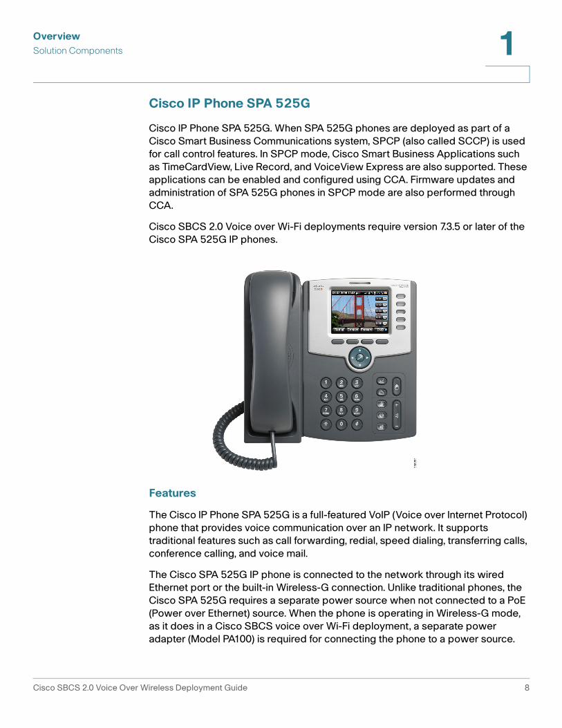
Cisco IP Phone SPA 525G
Cisco IP Phone SPA 525G. When SPA 525G phones are deployed as part of a Cisco Smart Business Communications system, SPCP (also called SCCP) is used for call control features. In SPCP mode, Cisco Smart Business Applications such as TimeCardView, Live Record, and VoiceView Express are also supported. These applications can be enabled and configured using CCA. Firmware updates and administration of SPA 525G phones in SPCP mode are also performed through CCA.
Cisco SBCS 2.0 Voice over Wi-Fi deployments require version 7.3.5 or later of the Cisco SPA 525G IP phones.
Features
The Cisco IP Phone SPA 525G is a full-featured VoIP (Voice over Internet Protocol) phone that provides voice communication over an IP network. It supports traditional features such as call forwarding, redial, speed dialing, transferring calls, conference calling, and voice mail.
The Cisco SPA 525G IP phone is connected to the network through its wired Ethernet port or the built-in Wireless-G connection. Unlike traditional phones, the Cisco SPA 525G requires a separate power source when not connected to a PoE (Power over Ethernet) source. When the phone is operating in Wireless-G mode, as it does in a Cisco SBCS voice over Wi-Fi deployment, a separate power adapter (Model PA100) is required for connecting the phone to a power source.
Cisco SBCS 2.0 Voice Over Wireless Deployment Guide 8

OverviewSolution Components 1
IMPORANT Although the Cisco SPA 525G has an additional Ethernet port that allows a computer to be connected to the network through the IP phone, this option is only available when the phone is connected to the network via the wired Ethernet port.
The SPA 525G has a 320 x 240 color, 3.2" inch LCD screen and provides up to five telephone extensions. It provides the following hardware features:
• Two (2) Ethernet 10/100 Mbps ports
• 802.3af Power over Ethernet support
• USB 2.0 host port for connecting a USB memory device to play MP3 files
• Bluetooth capability for headset support
• 2.5-mm stereo earphone jack for headset
• Wireless-G client
• Kensington security slot
• Phone VPN client (requires SPA 525G firmware version 7.4.2 or later)
Cisco SPA 525G IP phones support headsets from different manufacturers. For the latest supported models, contact your reseller. Additional information can be found at the following manufacturer’s websites:
• Plantronics — http://www.plantronics.com
• Jabra — http://www.jabra.com
More information about the Cisco IP Phone SPA 525G is available on Cisco.com at the following URL:
http://www.cisco.com/en/US/products/ps1067/index.html
Documentation for SPA 525G phones is available on Cisco.com at the following URL:
www.cisco.com/en/US/products/ps10499/tsd_products_support_series_home.html
Available guides include:
• Cisco Small Business Pro IP Phone SPA 525G Quick Start Guide
• Cisco Small Business Pro SPA 500 Series and WIP310 IP Phone Administration Guide
• Release Notes for Cisco Small Business Pro IP Phone SPA 525G Firmware Version 7.3.5
Cisco SBCS 2.0 Voice Over Wireless Deployment Guide 9
OverviewSolution Components 1
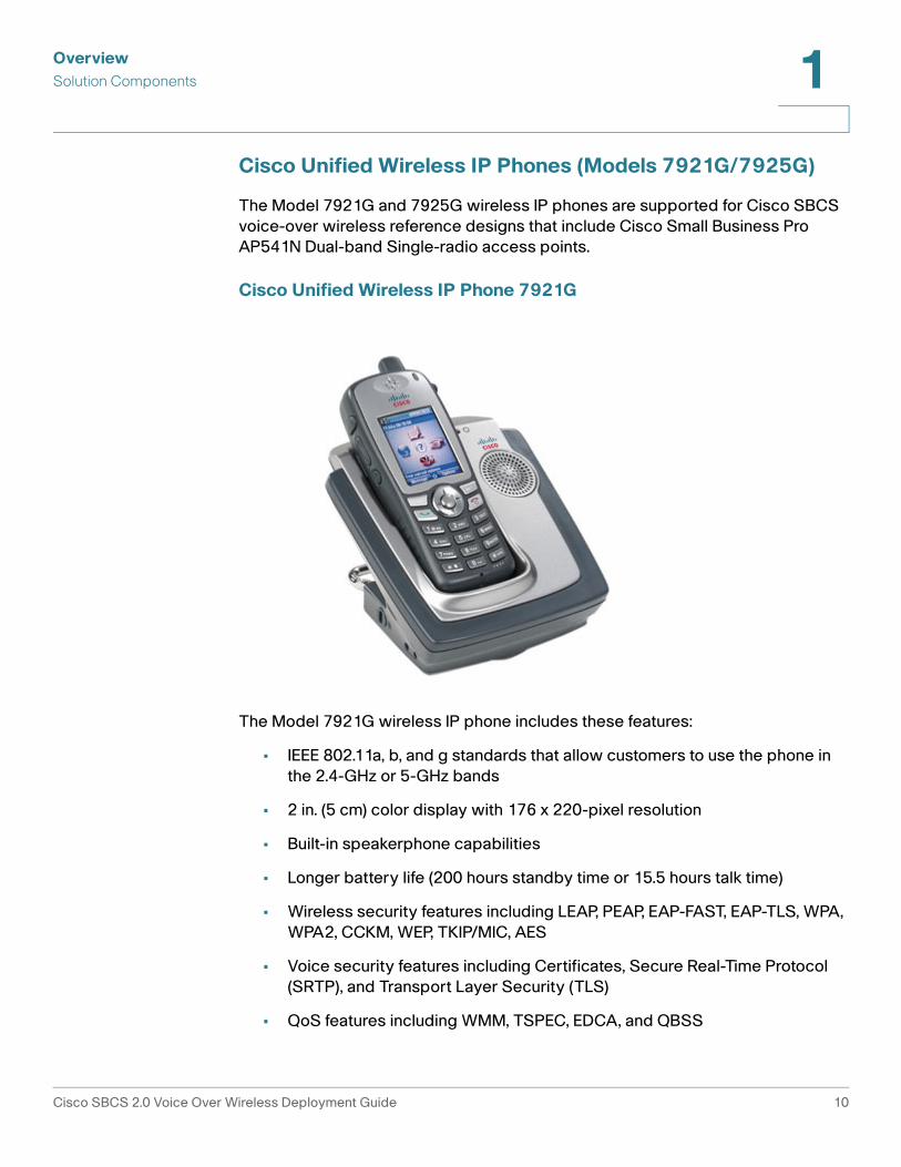
Cisco Unified Wireless IP Phones (Models 7921G/7925G)
The Model 7921G and 7925G wireless IP phones are supported for Cisco SBCS voice-over wireless reference designs that include Cisco Small Business Pro AP541N Dual-band Single-radio access points.
Cisco Unified Wireless IP Phone 7921G
The Model 7921G wireless IP phone includes these features:
• IEEE 802.11a, b, and g standards that allow customers to use the phone in the 2.4-GHz or 5-GHz bands
• 2 in. (5 cm) color display with 176 x 220-pixel resolution
• Built-in speakerphone capabilities
• Longer battery life (200 hours standby time or 15.5 hours talk time)
• Wireless security features including LEAP, PEAP, EAP-FAST, EAP-TLS, WPA, WPA2, CCKM, WEP, TKIP/MIC, AES
• Voice security features including Certificates, Secure Real-Time Protocol (SRTP), and Transport Layer Security (TLS)
• QoS features including WMM, TSPEC, EDCA, and QBSS
Cisco SBCS 2.0 Voice Over Wireless Deployment Guide 10
OverviewSolution Components 1
More information on the Cisco Unified Wireless IP Phone 7921G is available on Cisco.com at the following URL:
http://www.cisco.com/en/US/products/ps7071/index.html
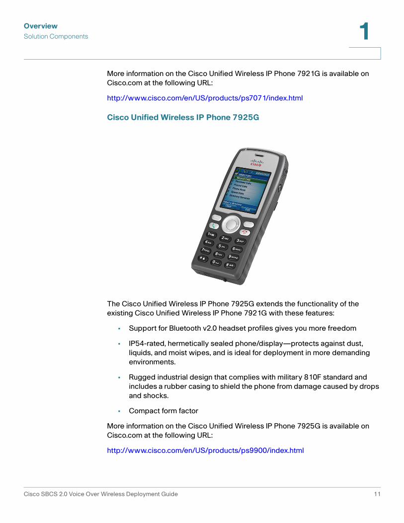
Cisco Unified Wireless IP Phone 7925G
The Cisco Unified Wireless IP Phone 7925G extends the functionality of the existing Cisco Unified Wireless IP Phone 7921G with these features:
• Support for Bluetooth v2.0 headset profiles gives you more freedom
• IP54-rated, hermetically sealed phone/display—protects against dust, liquids, and moist wipes, and is ideal for deployment in more demanding environments.
• Rugged industrial design that complies with military 810F standard and includes a rubber casing to shield the phone from damage caused by drops and shocks.
• Compact form factor
More information on the Cisco Unified Wireless IP Phone 7925G is available on Cisco.com at the following URL:
http://www.cisco.com/en/US/products/ps9900/index.html
Cisco SBCS 2.0 Voice Over Wireless Deployment Guide 11

OverviewSolution Components 1
Cisco SBCS 2.0 Voice Over Wireless Deployment Guide 12

2
Planning a Cisco SBCS Voice Over Wi-Fi Deployment
This chapter discusses network planning guidelines for Cisco SBCS 2.0 voice over Wi-Fi deployments using the reference designs described in Chapter 3, “Reference Designs for Cisco SBCS 2.0 Voice Over Wi-Fi Deployments.”
IMPORTANT Consult the wireless regulatory compliance information to verify that the wireless IP phones and access points deployed for your solution are certified for operation in your country.
NOTE Wireless data network design is outside the scope of this guide.
The following topics are covered:
• Overview, page 14
• Wireless Mobility, page 14
• Quality of Service (QoS), page 15
• Radio Frequency (RF) Design Guidelines, page 16
• Wireless Access Point Placement and Signal Coverage, page 16
• Wireless Site Survey, page 20
• Wireless Voice Security, page 22
Cisco SBCS 2.0 Voice Over Wireless Deployment Guide 13

Planning a Cisco SBCS Voice Over Wi-Fi DeploymentOverview 2
Overview
The Cisco SBCS 2.0 Voice over Wi-Fi solution is designed for small businesses who want a flexible, affordable, full-featured business communications system that is reliable, easy to deploy or move, requires no new wiring, and helps the business operate more efficiently and effectively. It offers growth and reduced costs, unlike point product offerings from competitors that are potentially incompatible and could require complex integration efforts, resulting in a higher overall cost of ownership.
Traditionally, small businesses wishing to deploy IP telephony had the option of replacing desktop phones with IP phones that use a wired connection to IP resources. As a result, this often required business to upgrade the network infrastructure to support voice features or employ skilled IT staff with technical knowledge to configure the end-to-end solution. SBCS provides small business customers with a way to overcome some of these technical challenges when deploying converged voice and data by using wireless media as the transport mechanism. The only investment required for the small business is the wireless infrastructure and wireless IP phone endpoints.
Wireless voice deployments are well-suited to businesses housed in historic buildings where network cabling is limited or non-existent or mobile business locations such as trailers, kiosks, and oil rigs.
Another advantage is rapid deployment. Cisco Configuration Assistant (CCA), provides an easy-to-use GUI for configuring the solution that enables customers to save time when deploying the reference designs presented in this guide.
Wireless Mobility
Wireless voice mobility is the ability for Wi-Fi phones to roam across different access points, while maintaining call states and voice quality.
The reference designs described in this guide do not require a wireless LAN controller for wireless voice mobility. Cisco Small Business Pro AP541N access points support AP clustering, which provides controller-like capabilities that support client-based roaming.
Wireless roaming between AP541N access points and the integrated access point on the UC 500 or SA 500, however, is not supported. If there is a UC 500W with integrated wireless AP at the customer site and AP 541s, the voice SSID should only be configured on AP541Ns.
Cisco SBCS 2.0 Voice Over Wireless Deployment Guide 14

Planning a Cisco SBCS Voice Over Wi-Fi DeploymentQuality of Service (QoS) 2
Customers who want to use controller-assisted roaming for wireless mobility can deploy a WLC 526 controller with Cisco Model 7921G wireless IP phones. For more information, refer to the Guide to Configuring Cisco 7921 Phones in an SBCS Environment, available on Cisco.com at the following URL:
http://www.cisco.com/en/US/products/ps7320/products_white_paper09186a0080973d69.shtml#design_sbcs
Quality of Service (QoS)
QoS refers to the capability of a network to provide differentiated service to selected network traffic over various transport technologies. QoS provides the following benefits:
• Capability for network resources to be shared more efficiently and expedite the handling of mission-critical applications
• Management of time-sensitive multimedia and voice application traffic to ensure that this traffic receives higher priority, greater bandwidth, and less delay than best-effort data traffic
With QoS, bandwidth can be managed more efficiently across LANs, including WLANs. QoS provides enhanced and reliable network service by:
• Supporting dedicated bandwidth for critical users and applications
• Controlling jitter and latency (required for real-time voice traffic)
• Managing and minimizing network congestion
• Setting network traffic priorities
The Cisco SBCS 2.0 voice over Wi-Fi solution provides QoS by:
• Offering separate VLANs for voice and data
• Giving priority to voice traffic over the shared RF (radio frequency) link
For best performance, WMM/802.11e and the “Optimized for Voice” QoS Presets must be enabled on Cisco AP541N access points using the AP541N Configuration Utility.
Cisco SBCS 2.0 Voice Over Wireless Deployment Guide 15
Planning a Cisco SBCS Voice Over Wi-Fi DeploymentRadio Frequency (RF) Design Guidelines 2
Radio Frequency (RF) Design Guidelines
Cisco SBCS 2.0 Voice over Wi-Fi deployments using the AP541N access points support a mix of wireless-B, G, and N clients. The AP541N also supports a mix of wireless-A and -N clients, depending on how the mode for the radio is configured.
The most important factor to consider in an SBCS Voice over Wi-Fi deployment with wireless IP phones is coverage—that is, how far the signal can reach wireless clients with acceptable quality. To achieve reliable voice service, a Voice over Wireless LAN (VoWLAN) cell boundary of -67 dBm or better is recommended.
Wireless Access Point Placement and Signal Coverage
The physical environment affects performance of any wireless access point, and careful placement of access points is critical in providing reliable coverage throughout the office. It is important to note that every obstacle placed between an access point and wireless client will degrade the signal to some extent. Leaded glass, metal, concrete floors, water, and walls will all inhibit the signal and reduce range. In addition, electrical equipment such as heavy machinery or items such as microwave ovens can generate interference that also degrades signal quality in the immediate vicinity.
Small installations may be implemented relatively easily and using only basic tools such as wireless site survey applications bundled with many wireless client devices. Access points may be initially positioned in a convenient location central to the area requiring coverage, and then adjusted based on the actual coverage as measured using a wireless client device.
Keep the following general rules in mind when placing access points:
• Access points should be placed as high as possible to ensure the best possible coverage.
• Access points should not be placed close to metal cabinets, concrete walls, or other obstacles.
• Access points should not be placed on a metallic surface such as a cabinet or aluminum heat dissipater.
• Access points should not be placed within any type of enclosure.
• Antennas should be vertically oriented for most uses. Adjusting the antenna angle may affect performance.
Cisco SBCS 2.0 Voice Over Wireless Deployment Guide 16

Planning a Cisco SBCS Voice Over Wi-Fi DeploymentWireless Access Point Placement and Signal Coverage 2
For the Cisco SBCS 2.0 voice-over-wireless deployment reference designs, these types of access points can be deployed:
• The UC 500 integrated access point
• External Cisco AP541N access points
Theoretically, the AP541N and UC 500 integrated access points can serve an area of 5,000 square feet (464 m2). However, because of the nature of voice traffic, and the fact that a typical office building has walls, ceiling, RF interference, and other factors that can affect signal strength, the recommended effective coverage area defined for the solution has been reduced to provide a safety margin:
• UC 500 integrated access point recommended coverage area — 2,500 sq ft (232 m2)
• Single external AP541N access point coverage area — 2500 sq ft (232 m2)
Cisco AP 541N access points support clustering for voice over Wi-Fi client roaming. This means that you can increase the coverage area by adding more APs (for example, with two AP541Ns, the coverage area increases to 5000 square feet (minus the recommended 20% coverage area overlap); with three AP541Ns it increases to 7500 square feet (minus the recommended 20% coverage area overlap), and so on, up to 10 access points).
IMPORTANT The coverage areas described here are guidelines. Cisco strongly recommends that you conduct a wireless RF site survey at the customer site to account for RF interference.
The diagrams in Figure 1 show optimal placement of a single UC 520W or UC 540W with integrated wireless and a single external AP541N access point in an office building without excessive obstructions. Only two-dimensional coverage is considered. For multi-floor deployments, you cannot assume the same distances, as floors and ceilings are significant obstructions that can greatly reduce signal strength.
Cisco SBCS 2.0 Voice Over Wireless Deployment Guide 17

Planning a Cisco SBCS Voice Over Wi-Fi DeploymentWireless Access Point Placement and Signal Coverage 2
Figure 1 Coverage Area for Single UC 520W, UC 540W, or External AP541N
The diagram in Figure 2 shows a worst-case scenario in which the UC 500 with an integrated access point is positioned at the furthest point possible (for example, when the office telecommunications equipment is located in one corner of the office). When the access point is placed in the corner of an office, the effective signal reach is greatly reduced because a large part of the coverage area is outside the office.
Cisco SBCS 2.0 Voice Over Wireless Deployment Guide 18

Planning a Cisco SBCS Voice Over Wi-Fi DeploymentWireless Access Point Placement and Signal Coverage 2
Figure 2 Worst-Case Placement of UC 500 with Integrated Access Point
Note that a worst-case scenario for the external AP541N is not shown. This is because it is a standalone device, and there is greater flexibility for placement.
Cisco SBCS 2.0 Voice Over Wireless Deployment Guide 19
Planning a Cisco SBCS Voice Over Wi-Fi DeploymentWireless Site Survey 2
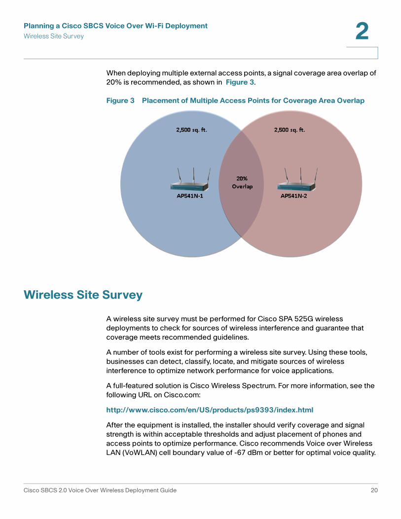
When deploying multiple external access points, a signal coverage area overlap of 20% is recommended, as shown in Figure 3.
Figure 3 Placement of Multiple Access Points for Coverage Area Overlap
Wireless Site Survey
A wireless site survey must be performed for Cisco SPA 525G wireless deployments to check for sources of wireless interference and guarantee that coverage meets recommended guidelines.
A number of tools exist for performing a wireless site survey. Using these tools, businesses can detect, classify, locate, and mitigate sources of wireless interference to optimize network performance for voice applications.
A full-featured solution is Cisco Wireless Spectrum. For more information, see the following URL on Cisco.com:
http://www.cisco.com/en/US/products/ps9393/index.html
After the equipment is installed, the installer should verify coverage and signal strength is within acceptable thresholds and adjust placement of phones and access points to optimize performance. Cisco recommends Voice over Wireless LAN (VoWLAN) cell boundary value of -67 dBm or better for optimal voice quality.
Cisco SBCS 2.0 Voice Over Wireless Deployment Guide 20

Planning a Cisco SBCS Voice Over Wi-Fi DeploymentWireless Site Survey 2
Cisco 7921G/7925G Wireless IP Phone Site Survey Utility
Cisco 7921G/7925G phones have a Site Survey utility that can be used to actively and passively scan the wireless medium across all channels and locate APs that belong to the Basic Service Set (BSS). The results of the scans can be used to help identify areas of low coverage, if any, and to determine whether the APs are configured consistently. When you start the Site Survey utility, the phone disassociates from the current AP and remains disassociated for the duration of the operation.
• To access the Site Survey utility on the Cisco 7921G wireless IP phone, choose Settings > Status > Site Survey.
The phone displays a list of access points within range that have the same SSID and security settings as the phone. To see more information about an AP, scroll to the desired line and press Details.
• To verify the ability to roam between APs, walk through all areas where phones are used and take readings. Approach areas from different directions to assure successful roaming conditions.
• Adjust AP and antenna placement and AP power settings to provide approximately 20 percent coverage overlap.
For more information, see the Cisco Unified Wireless IP Phone 7921G Administration Guide for Release 7.0 or the Cisco Unified Wireless IP Phone 7925G Administration Guide, Release 7.0, available on Cisco.com.
Viewing Signal Strength on SPA 525G IP Phones
The Cisco IP Phone SPA 525G displays the received signal strength from its associated access point. To check the signal level during installation, press the Setup button on the phone and navigate to Network Configuration > Wireless > Wireless Status.
Cisco SBCS 2.0 Voice Over Wireless Deployment Guide 21
Planning a Cisco SBCS Voice Over Wi-Fi DeploymentWireless Voice Security 2
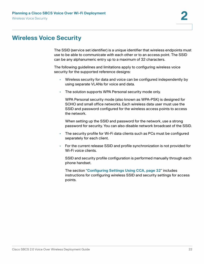
Wireless Voice Security
The SSID (service set identifier) is a unique identifier that wireless endpoints must use to be able to communicate with each other or to an access point. The SSID can be any alphanumeric entry up to a maximum of 32 characters.
The following guidelines and limitations apply to configuring wireless voice security for the supported reference designs:
• Wireless security for data and voice can be configured independently by using separate VLANs for voice and data.
• The solution supports WPA Personal security mode only.
WPA Personal security mode (also known as WPA-PSK) is designed for SOHO and small office networks. Each wireless data user must use the SSID and password configured for the wireless access points to access the network.
When setting up the SSID and password for the network, use a strong password for security. You can also disable network broadcast of the SSID.
• The security profile for Wi-Fi data clients such as PCs must be configured separately for each client.
• For the current release SSID and profile synchronization is not provided for Wi-Fi voice clients.
SSID and security profile configuration is performed manually through each phone handset.
The section “Configuring Settings Using CCA, page 32” includes instructions for configuring wireless SSID and security settings for access points.
Cisco SBCS 2.0 Voice Over Wireless Deployment Guide 22

3
Reference Designs for Cisco SBCS 2.0 Voice Over Wi-Fi Deployments
This chapter covers components, design characteristics, target customers, deployment limitations, and caveats for supported reference designs.
• Overview
• Reference Design #1 — Small Office, Up to 8 Wi-Fi Voice and Data Users, Integrated UC 500 Wireless
• Reference Design #2 — Larger Offices, 16 to 48 Wi-Fi Voice Users, AP541N Access Points, 50+ Wi-Fi Data Clients
• Guidelines, Limitations, and Caveats
Overview
Table 1 summarizes components and design characteristics each of the voice over Wi-Fi reference designs that are supported in SBCS 2.0.
Although it is possible to deploy a system outside these limits, Cisco strongly recommends that customers deploy one of these designs as specified.
These reference designs can be combined with existing wired-line devices such as Cisco Small Business Pro ESW 500 Series switches, Cisco Catalyst Express CE 520 switches, Cisco SR 500 Series secure routers, and wired IP phones (for example, Cisco Model 7960 IP phones).
Cisco SBCS 2.0 Voice Over Wireless Deployment Guide 23

Reference Designs for Cisco SBCS 2.0 Voice Over Wi-Fi DeploymentsReference Design #1 — Small Office, Up to 8 Wi-Fi Voice and Data Users, Integrated UC 500 Wireless 3
NOTE Phone capacity recommendations for these reference designs address wireless phone capacity only. The maximum phone capacity for deployments with a combination of wired and wireless phones is determined by the license capacity of the UC 500 platform being deployed.
The following notes apply to the above summary:
• Reference design #1 supports all UC 520 and UC 540 wireless SKUs.
• Reference design #2 supports all UC 500 SKUs.
Reference Design #1 — Small Office, Up to 8 Wi-Fi Voice and Data Users, Integrated UC 500 Wireless
Reference design #1 is a perfect fit for a small business with up to 8 users who are housed in a single workspace of up to 2,500 square feet. One of the benefits of this design is that the small business can take advantage of the full license capacity of the UC 520W and UC 540W 8-user SKUs to deploy an all-wireless solution. In this design, a single Cisco UC 520W or UC 540W with an integrated wireless AP is used for both voice and data traffic.
QoS settings allow for the co-existence of voice and data on the wireless network, while maintaining voice quality. When no calls are present on the system and all phones are in an idle state, computers can take advantage of the full throughput offered by the Wireless-G radio on the integrated UC 500 access point. IP phone-to-IP phone communication within a site over the wireless LAN uses toll-quality voice compression (G.711 codec).
Table 1 Summary of Supported Voice Over Wi-Fie Reference Designs for SBCS 2.0
Reference Design
Access Points Number of APs
Maximum Wi-Fi Voice Clients
Maximum Wi-Fi Data Clients
Voice over Wi-Fi Roaming?
Wireless Coverage Area in sq ft (m2)
#1 UC 520W or UC 540W with integrated wireless
1 8 8 N/A Up to 2,500 sq ft (232 m2)
#2 AP541N Up to 10 16 per AP;48 total
50 per AP Yes (with 2 or more APs)
2500 sq ft (232 m2) per AP deployed, minus 20% signal coverage area overlap
Cisco SBCS 2.0 Voice Over Wireless Deployment Guide 24
Reference Designs for Cisco SBCS 2.0 Voice Over Wi-Fi DeploymentsReference Design #1 — Small Office, Up to 8 Wi-Fi Voice and Data Users, Integrated UC 500 Wireless 3
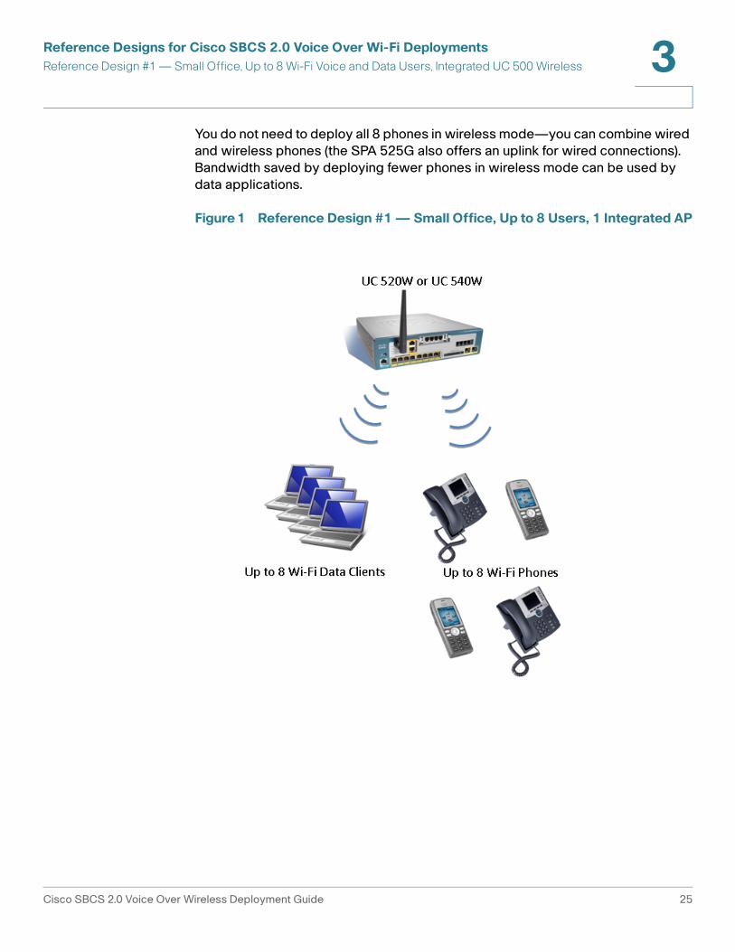
You do not need to deploy all 8 phones in wireless mode—you can combine wired and wireless phones (the SPA 525G also offers an uplink for wired connections). Bandwidth saved by deploying fewer phones in wireless mode can be used by data applications.
Figure 1 Reference Design #1 — Small Office, Up to 8 Users, 1 Integrated AP
Cisco SBCS 2.0 Voice Over Wireless Deployment Guide 25
Reference Designs for Cisco SBCS 2.0 Voice Over Wi-Fi DeploymentsReference Design #2 — Larger Offices, 16 to 48 Wi-Fi Voice Users, AP541N Access Points, 50+ Wi-Fi Data Clients
3
Reference Design #2 — Larger Offices, 16 to 48 Wi-Fi Voice Users, AP541N Access Points, 50+ Wi-Fi Data Clients
Reference design #2 is a scalable design that can be used to deploy voice over Wi-Fi for businesses who require support for 16 to 48 Wi-Fi voice users, 50 or more wireless data clients, wireless voice mobility, or a larger coverage area.
To increase capacity, add AP541N access points and phones and, if needed, purchase and install additional UC 500 user licenses.
The QoS settings required to guarantee voice quality in the presence of data traffic must be manually configured on the AP541N for this design.
In this design:
• All UC 500 models and SKUs are supported. The number of user licenses on the UC 500 must be equal to or greater than the number of phones deployed.
You cannot combine external APs with the integrated access point on the UC 500. When external APs are used with a UC 500W with integrated wireless, remove the SSID configuration on the UC 500W.
• From 1 to 10 external AP541N access points can be deployed. Each AP provides an additional 16 Wi-Fi voice clients (up to a maximum of 48), 50 Wi-Fi data clients, and 2500 square feet of coverage area (232 square meters).
• Clustering can be enabled on AP541N access points to support wireless mobility using client-based roaming
• Separate SSIDs are configured on the AP541N for voice and data.
• A mix of wireless-B, G, and N wireless clients are supported.
You do not need to deploy all phones in wireless mode—you can combine wired and wireless phones (the SPA 525G also offers an uplink for wired connections). Bandwidth saved by deploying fewer phones in wireless mode can be used by data applications.
Cisco SBCS 2.0 Voice Over Wireless Deployment Guide 26

Reference Designs for Cisco SBCS 2.0 Voice Over Wi-Fi DeploymentsReference Design #2 — Larger Offices, 16 to 48 Wi-Fi Voice Users, AP541N Access Points, 50+ Wi-Fi Data Clients
3
Figure 2 Reference Design #2, Single AP541N Access Point Option
Cisco SBCS 2.0 Voice Over Wireless Deployment Guide 27

Reference Designs for Cisco SBCS 2.0 Voice Over Wi-Fi DeploymentsGuidelines, Limitations, and Caveats 3
Guidelines, Limitations, and Caveats
The following limitations and caveats apply to voice over Wi-Fi deployments with Cisco SPA 525G IP phones for SBCS 2.0:
• The reference designs do not support a combination of UC 500 integrated APs and external AP541N APs.
• WPA-PSK security must be used.
• Cisco SPA 525G phones are not supported for use with any 3rd-party wireless AP.
• These reference designs supports SCCP phone registrations with UC5xx only; they do not support SIP endpoint registrations with a SIP provider.
• The Cisco IP Phone SPA 525G is a desktop phone with a built-in Wireless-G client that is served by a single access point. It is not a wireless mobile phone. When the Cisco IP Phone SPA 525G is operating in Wireless-G mode, it still requires a connection to power.
• The CCA Wireless Setup Wizard cannot be used to automate configuration of AP541N access points or SPA 525G, 7921G, and 7925G wireless IP phones profiles. The APs must be manually configured using CCA in expert mode, and the wireless profiles must be manually configured on the phones.
• The Cisco IP Phone SPA 525G is supported for teleworkers in wired mode only.
• Unicast paging groups are required with Cisco SPA 525G wireless phones. A maximum of ten (10) phones can be in a unicast paging group.
• Multicast Music on Hold (MoH) for internal calls (IP phone-to-IP phone) is not supported for this solution and must be disabled using CCA.
The procedures under Configuring Settings Using CCA, page 32 include instructions for disabling MoH for internal calls.
Cisco SBCS 2.0 Voice Over Wireless Deployment Guide 28

4
Installing, Configuring, and Administering SBCS 2.0 Voice over Wi-Fi Deployments
This chapter covers the following topics:
• Initial Installation and Configuration Steps, page 29
• Administration Tasks After Initial Installation, page 40
Initial Installation and Configuration Steps
This section contains the following procedures for first-time installation and configuration of a Cisco SBCS voice over Wi-Fi deployment:
• Before You Begin, page 30
• Creating a CCA Customer Site, page 31
• Configuring Settings Using CCA, page 32
• Configuring Settings Using the AP541N Configuration Utility, page 35
• Configuring Wireless Profile Settings on the IP Phones, page 36
• Verifying the Installation, page 40
Cisco SBCS 2.0 Voice Over Wireless Deployment Guide 29

Installing, Configuring, and Administering SBCS 2.0 Voice over Wi-Fi DeploymentsInitial Installation and Configuration Steps 4
Before You Begin
Before installing a Cisco SBCS voice over Wi-Fi deployment for the first time, make sure that the following requirements are met:
• Each of the SPA 525G phones that will be connected wirelessly must have a Model PA100 external power supply. The power supply does not ship with the phone and must be ordered separately.
• Verify that you have the correct number and type of access points for the deployment.
• Verify that the UC 500 has software licensing for the number of phones being deployed.
• Download and install Cisco Configuration Assistant, Version 2.2 or later to a local PC to be used for the installation. The CCA software is free and available from Cisco.com at the following location:
www.cisco.com/go/configassist
You must be a registered Cisco.com user to download the software; no other access privileges are required.
• Create a customer site that includes the AP541N access point, UC 500, IP phones, and other SBCS components as described in Creating a CCA Customer Site, page 31.
• Verify that the UC 500 has been upgraded to Cisco SBCS Software Package Version 8.0.0 or later, which includes the most current SPA 525G phone firmware, voice mail software, and other files.
To view the version of Cisco IOS currently installed on the UC 500 using CCA, open the Dashboard (Home > Dashboard) and check the IOS Version displayed on the System Status item.
To perform software upgrades using CCA, navigate to Maintenance, choose Software Upgrade, and follow the instructions in the CCA online help.
• If this is a new installation, the procedures in this guide assume that you have already configured the rest of the system using CCA in expert mode or by running the Telephony Setup Wizard.
Cisco SBCS 2.0 Voice Over Wireless Deployment Guide 30
Installing, Configuring, and Administering SBCS 2.0 Voice over Wi-Fi DeploymentsInitial Installation and Configuration Steps 4
Creating a CCA Customer Site
If you have not already done so, create a CCA customer site that includes the UC 500, AP541N access points, IP phones, and other SBCS components. Upgrade software on these devices if needed.
NOTE Before launching CCA, disable any third-party FTP or TFTP server running on the PC and make sure that firewall software running on the PC does not block access to the UC 500 or the CUE module on the UC 500. If the PC has a dual network interface card (NIC), make sure that only one network interface is enabled.
For more detailed instructions on creating a customer site, see the Cisco Configuration Assistant Smart Business Communications System Administrator Guide or the CCA online help. The CCA administration guide is available on Cisco.com at the following URL:
http://www.cisco.com/en/US/products/ps7287/prod_maintenance_guides_list.html
STEP 1 Connect each external AP541N access point to a PoE port on the UC 500 platform or ESW 500 Series or CE 520 switch in the customer site and allow the access points to boot up.
STEP 2 Connect a PC to one of the PoE ports on the UC 500 platform or connected switch and launch CCA.
STEP 3 Create a customer site using the LAN IP address (for example, 192.168.10.1) of the UC 500 platform as the starting IP address for discovering devices. The AP541N should be listed as one of the devices discovered.
STEP 4 Connect to the customer site.
STEP 5 When prompted for authentication, enter the username and password for any managed devices that are discovered.
The default username and password for the UC 500 and the AP541N are both cisco/cisco.
STEP 6 Verify that the UC 500 and any external access points are discovered and displayed in the network Topology View in CCA.
STEP 7 In the Topology View, right-click on the icon for each AP541N and choose Add to Site if the device is not already shown as a member of the customer site.
STEP 8 If you have not upgraded the UC 500 software package to version 8.0.0 or later, back up the configuration (Maintenance > Configuration Archive), then go to
Cisco SBCS 2.0 Voice Over Wireless Deployment Guide 31

Installing, Configuring, and Administering SBCS 2.0 Voice over Wi-Fi DeploymentsInitial Installation and Configuration Steps 4
Maintenance > Software Upgrade and follow the instructions in the online help for upgrading the UC 500.
STEP 9 In the Software Upgrade window, select each AP541N AP and verify that it is running the latest software. Firmware version 1.8.0 or later is required. Upgrade devices as needed.
When upgrading AP541N access points, choose Standard in the Upgrade Settings window. The upgrade file for the AP541N will have a .tar extension, for example, AP541N-K9.1.8.0.tar. The access points are restarted after the upgrade is applied.
STEP 10 Verify that ESW 500 Series switches are running the latest firmware. Upgrade these devices if needed.
Configuring Settings Using CCA
Next, you will use CCA to configure device properties and wireless settings on access points and the UC 500:
• Configure device properties, such as hostname, administrative username, and admin password.
• Disable Music on Hold on the UC 500.
• Configure wireless SSID settings for each access point.
STEP 1 Choose Configure > Device Properties > Hostname from the feature bar.
STEP 2 In the Hostname window, select each external AP and edit the default Hostname of AP541N-A-K9.
The hostname you enter will help you to identify the AP and its location in the network topology.
STEP 3 For security reasons, change the default password on each AP541N. To do this, perform these steps on each of the APs:
a. Choose Configure > Device Properties > Users and Passwords from the feature bar.
b. In the Hostname field, select the AP541N whose password you want to change.
c. Enter the new password, then re-enter it for confirmation.
d. Click OK.
Cisco SBCS 2.0 Voice Over Wireless Deployment Guide 32
Installing, Configuring, and Administering SBCS 2.0 Voice over Wi-Fi DeploymentsInitial Installation and Configuration Steps 4
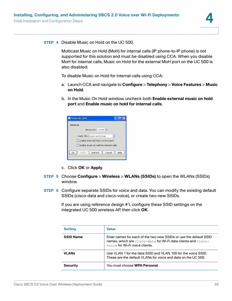
STEP 4 Disable Music on Hold on the UC 500.
Multicast Music on Hold (MoH) for internal calls (IP phone-to-IP phone) is not supported for this solution and must be disabled using CCA. When you disable MoH for internal calls, Music on Hold for the external MoH port on the UC 500 is also disabled.
To disable Music on Hold for internal calls using CCA:
a. Launch CCA and navigate to Configure > Telephony > Voice Features > Music on Hold.
b. In the Music On Hold window, uncheck both Enable external music on hold port and Enable music on hold for internal calls.
c. Click OK or Apply.
STEP 5 Choose Configure > Wireless > WLANs (SSIDs) to open the WLANs (SSIDs) window.
STEP 6 Configure separate SSIDs for voice and data. You can modify the existing default SSIDs (cisco-data and cisco-voice), or create two new SSIDs.
If you are using reference design #1, configure these SSID settings on the integrated UC 500 wireless AP, then click OK.
Setting Value
SSID Name Enter names for each of the two new SSIDs or use the default SSID names, which are cisco-data for Wi-Fi data clients and cisco-voice for Wi-Fi voice clients.
VLANs Use VLAN 1 for the data SSID and VLAN 100 for the voice SSID. These are the default VLANs for voice and data on the UC 500.
Security You must choose WPA Personal.
Cisco SBCS 2.0 Voice Over Wireless Deployment Guide 33

Installing, Configuring, and Administering SBCS 2.0 Voice over Wi-Fi DeploymentsInitial Installation and Configuration Steps 4
If you are using reference design #2, configure these settings on each AP541N for the voice and data SSIDs, then click OK.
STEP 7 If you are using reference design 2 and you have a UC 500 with an integrated access point, select the UC 500 hostname in the WLANs (SSIDs) window and delete the default voice and data SSIDs. This effectively disables the wireless on the UC 500.
STEP 8 Exit CCA. When prompted, save the configuration for All Devices.
If your deployment includes AP541N access points, perform the steps described in Configuring Settings Using the AP541N Configuration Utility, page 35. If not, perform the steps described in Configuring Wireless Profile Settings on the IP Phones, page 36.
Pre-shared Key Enter from 8 to 32 characters for the pre-shared key.
Broadcast in Beacon Recommend disabling this setting for security reasons.
Setting Value
SSID Name Enter names for each of the two new SSIDs or use the default SSID names, which are cisco-data for Wi-Fi data clients and cisco-voice for Wi-Fi voice clients.
VLANs Use VLAN 1 for the data SSID and VLAN 100 for the voice SSID. These are the default VLANs for voice and data on the UC 500.
Security You must choose WPA Personal.
Pre-shared Key Enter from 8 to 32 characters for the pre-shared key.
Broadcast Key Refresh Rate
Leave the default value of 300 seconds.
MAC Authentication Type
Set to Disabled.
Setting Value
Cisco SBCS 2.0 Voice Over Wireless Deployment Guide 34

Installing, Configuring, and Administering SBCS 2.0 Voice over Wi-Fi DeploymentsInitial Installation and Configuration Steps 4
Configuring Settings Using the AP541N Configuration Utility
If your voice over Wi-Fi deployment uses AP541N access points, you must configure these settings manually on the each AP541 using the web-based AP541 Configuration Utility.
• Verify that the wireless radio is on and the mode is set correctly
• Enable Wi-Fi Multi Media (WMM) for QoS and verify QoS settings on the AP
• Enable clustering for client-based roaming.
The AP541 Configuration Utility can be accessed from within CCA.
STEP 1 To access the Configuration Utility on the AP541N:
a. Go to the Topology view in CCA.
b. In the Topology view, right click on the icon for the AP541N you want to configure.
c. Choose Configuration Utility from the pop-up menu.
d. Log in to the AP541N. Use the new password you configured earlier.
STEP 2 To verify wireless radio settings and check the mode:
a. Click the Wireless tab and choose Radio Settings.
b. Choose the appropriate Region (country).
c. Verify that the Wireless Radio Interface is set to On.
d. Verify that the Mode is set to 802.11 b/g/n. This is required for maximum performance.
e. Click Apply.
Cisco SBCS 2.0 Voice Over Wireless Deployment Guide 35

Installing, Configuring, and Administering SBCS 2.0 Voice over Wi-Fi DeploymentsInitial Installation and Configuration Steps 4
STEP 3 To enable Wi-Fi Multi Media and verify QoS settings:
a. In the AP541N Configuration Utility, choose Wireless > QoS Parameters.
a. Under QoS Presets, verify that Optimized for Voice is selected.
a. Verify that Wi-Fi Multi Media (WMM) is enabled (required). If not, enable it.
a. Click Apply.
STEP 4 Enable clustering on the AP.
a. In the AP541N Configuration Utility, choose Cluster > Access Points
b. Under Clustering Options, enter the location for the AP and the name of the cluster.
IMPORTANT Once you configure the first AP, you MUST enter the same cluster name that you used on the first AP (the cluster name on all APs must match exactly; the name is case-sensitive).
c. Click Enable Clustering.
d. Click Apply.
To continue with the configuration, perform the steps described in Configuring Wireless Profile Settings on the IP Phones, page 36.
Configuring Wireless Profile Settings on the IP Phones
Wireless profile settings must be configured manually on each phone. The SSID and pre-shared key you use when configuring the wireless phone profile on the phones must exactly match those configured on the UC 500 or AP541N.
The exact steps very, depending on the type of phone you are configuring. For step-by-step instructions, see these sections:
• Enabling Wi-Fi Mode and Configuring Wireless Profile Settings on SPA 525G Phones, page 37
• Configuring Wireless Profile Settings on Cisco 7921G/7925G Phones, page 39
Cisco SBCS 2.0 Voice Over Wireless Deployment Guide 36

Installing, Configuring, and Administering SBCS 2.0 Voice over Wi-Fi DeploymentsInitial Installation and Configuration Steps 4
Enabling Wi-Fi Mode and Configuring Wireless Profile Settings on SPA 525G Phones
To enable Wi-Fi mode and manually configure the wireless profile on a Cisco SPA 525G IP phone, follow these steps.
STEP 1 Unpack and set up the Cisco SPA 525G IP phone.
STEP 2 Connect the phone to power using a PA100 power supply.
STEP 3 Enable Wi-Fi mode on the phone:
a. Press the settings button on the phone.
b. Use the down arrow key on the Navigation button to scroll to the Network Configuration option, then press the Select softkey.
c. Press the right arrow key on the Navigation button to enable Wi-Fi mode (Wi-Fi setting will change from OFF to ON).
d. Click Save.
e. Click Exit.
STEP 4 Configure the wireless profile for the phone:
a. On the Cisco SPA 525G phone, press the Setup button.
b. Navigate to Network Configuration > Wi-Fi Configuration > Wireless Profile.
The current profile is shown.
c. To delete the current profile, press the Option softkey, scroll to the Delete option, then press the Select softkey.
d. Choose OK when asked to confirm the profile deletion.
e. Press the Option softkey again.
f. Choose Add New, then press the Select softkey.
Cisco SBCS 2.0 Voice Over Wireless Deployment Guide 37

Installing, Configuring, and Administering SBCS 2.0 Voice over Wi-Fi DeploymentsInitial Installation and Configuration Steps 4
g. Enter the following setting to create the wireless voice profile.
h. Click Save.
i. Click Connect.
The phone should register with the UC 500 and display an extension.
STEP 5 Check the signal strength on the SPA 525G IP phone:
a. Verify that the wireless icon that displays signal strength appears at the top of the phone display.
b. Press the settings button on the phone and navigate to Network Configuration > Wireless > Wireless Status to check the signal strength level at the location of the phone.
STEP 6 If needed, use CCA to configure additional user extension settings for the phone. See the CCA online help for more information.
Setting Value
Security Mode Choose WPA2PSK.
Profile Enter a descriptive name for the profile, for example, “voice.”
SSID Enter the wireless voice SSID exactly as you configured it for the AP541N or UC 500 integrated AP (for example, cisco-voice).
Cipher Type Leave the default setting of TKIP.
WPA Shared Key Enter the pre-shared key exactly as you configured it for the AP541N or UC 500 integrated AP. The key must have at least 8 characters and can contain up to 32 characters.
Cisco SBCS 2.0 Voice Over Wireless Deployment Guide 38

Installing, Configuring, and Administering SBCS 2.0 Voice over Wi-Fi DeploymentsInitial Installation and Configuration Steps 4
Configuring Wireless Profile Settings on Cisco 7921G/7925G Phones
To configure wireless profile settings on Cisco 7921G and 7925G Wireless IP phones, follow these steps.
STEP 1 Make sure the phone is On.
STEP 2 From the top-level phone menu screen, click Settings (toolbox icon).
STEP 3 Scroll down to Network Profiles and press the center select button.
STEP 4 Choose Profile 1.
STEP 5 Press **#* to unlock configuration options for Profile 1.
STEP 6 With Profile 1 selected, choose View.
STEP 7 Scroll to WLAN Configuration and press the center select button.
STEP 8 Configure these parameters.
STEP 9 Click Options > Save when you are finished configuring settings on the phone.
The phone will restart, register with the UC500, receive and display an extension number, and associate with the AP. At this point, you should be able to make calls.
STEP 10 If needed, use CCA to configure additional user extension settings for the phone. See the CCA online help for more information.
Setting Value
SSID Click Change and enter the SSID for wireless voice EXACTLY as you configured it on the AP541N or UC500 integrated AP. The SSID is case-sensitive.
Security Mode Choose Auto (AKM)
UserName Leave blank
Password Leave blank
Key Style Leave this value set to ASCII.
Preshared Key Click Change and enter the pre-shared key EXACTLY as you configured it on the AP541N or UC 500 integrated AP.
Cisco SBCS 2.0 Voice Over Wireless Deployment Guide 39

Installing, Configuring, and Administering SBCS 2.0 Voice over Wi-Fi DeploymentsAdministration Tasks After Initial Installation 4
Verifying the Installation
After you have finished configuring access points and wireless IP phones, you should be able to make calls.
Save and back up your device configuration using CCA. To access these options in CCA:
• Choose Configure > Save Configuration to save the running configuration to the startup configuration. This ensures that the configuration is retained if the UC 500 or AP541Ns lose power or restart unexpectedly. Save the configuration for All Devices.
• Choose Maintenance > Configuration Archive to access back-up and restore options. Back up the configuration for all devices.
For more information, see the Cisco Configuration Assistant online help.
Administration Tasks After Initial Installation
The procedures in this section apply to administering a Cisco SBCS voice over Wi-Fi deployment after the initial installation:
• Adding Cisco AP541N Access Points, page 40
• Adding Phones, page 41
• Changing the Wireless Voice or Data Password (WPA Pre-Shared Key)
Adding Cisco AP541N Access Points
You can add up to 10 AP541N access points. To add access points follow the procedures in Configuring Settings Using CCA, page 32 and Configuring Settings Using the AP541N Configuration Utility, page 35.
When adding access points, make sure that the SSID name, pre-shared key, and cluster name exactly match those configured on the existing APs.
Cisco SBCS 2.0 Voice Over Wireless Deployment Guide 40
Installing, Configuring, and Administering SBCS 2.0 Voice over Wi-Fi DeploymentsAdministration Tasks After Initial Installation 4
Adding Phones
Each additional access point can support up to 16 Wi-Fi voice clients. The process for adding phones and configuring settings is the same as for the initial installation. See Configuring Wireless Profile Settings on the IP Phones, page 36.
Remember to save and back up your device configuration through CCA.
Changing the Wireless Voice or Data Password (WPA Pre-Shared Key)
Perform the following steps to change the password (pre-shared key) for the voice or data SSID.
NOTE Notify users immediately if the pre-shared key for the data network has been modified. Wireless settings for PCs connected wirelessly must be configured separately for each client.
STEP 1 Launch CCA and connect to the customer site.
STEP 2 From the feature bar in CCA, choose Configure > Wireless, then click WLANS (SSIDs). CCA reads in the configuration.
STEP 3 For each access point in the customer site:
a. In the WLANs (SSIDs) window, select the hostname that applies to the device that has the SSID information that you want to modify (that is, the hostname for the UC 500 with the integrated AP or the hostname for the AP541N access point).
b. Locate the SSID to modify (either cisco-voice or cisco-data, for example) and click on it to select it.
c. Modify the pre-shared key and apply the change.
d. Click OK.
STEP 4 Save and back up the configuration for all devices through CCA.
STEP 5 Manually edit the pre-shared key in the profile settings for all Wi-Fi data clients and wireless IP phones to exactly match the new key.
Cisco SBCS 2.0 Voice Over Wireless Deployment Guide 41

Installing, Configuring, and Administering SBCS 2.0 Voice over Wi-Fi DeploymentsAdministration Tasks After Initial Installation 4
Cisco SBCS 2.0 Voice Over Wireless Deployment Guide 42

A
Where to Go From Here
Cisco provides a wide range of resources to help you and your customer obtain the full benefits of the Cisco Smart Business Communications System (SBCS)and its components.
Support
Cisco Small Business Support Community
www.cisco.com/go/smallbizsupport
Online Technical Support and Documentation (Login Required)
www.cisco.com/support
Support Contacts (Phone) www.cisco.com/en/US/support/tsd_cisco_small_business _support_center_contacts.html
Software Downloads(Login Required)
Go to tools.cisco.com/support/downloads, and enter the model number in the Software Search box.
Product Resources and Documentation
Cisco Configuration Assistant (CCA)
www.cisco.com/en/US/products/go/configassist
Cisco AP541N Dual-band SIngle-radio access points
www.cisco.com/go/ap500
Cisco Smart Business Communications System (SBCS)
www.cisco.com/go/sbcs
Cisco Small Business
Cisco Partner Central for Small Business (Partner Login Required)
www.cisco.com/web/partners/sell/smb
Cisco Small Business Home www.cisco.com/smb
Marketplace www.cisco.com/go/marketplace
Cisco SBCS 2.0 Voice Over Wireless Deployment Guide 43

Where to Go From Here A
Cisco SBCS 2.0 Voice Over Wireless Deployment Guide 44