Embed Size (px)
Citation preview

Cisco Network Visibility Application on APIC-EM User Guide, Release1.4.0.xFirst Published: 2015-11-02
Last Modified: 2017-02-21
Americas HeadquartersCisco Systems, Inc.170 West Tasman DriveSan Jose, CA 95134-1706USAhttp://www.cisco.comTel: 408 526-4000 800 553-NETS (6387)Fax: 408 527-0883

THE SPECIFICATIONS AND INFORMATION REGARDING THE PRODUCTS IN THIS MANUAL ARE SUBJECT TO CHANGE WITHOUT NOTICE. ALL STATEMENTS,INFORMATION, AND RECOMMENDATIONS IN THIS MANUAL ARE BELIEVED TO BE ACCURATE BUT ARE PRESENTED WITHOUT WARRANTY OF ANY KIND,EXPRESS OR IMPLIED. USERS MUST TAKE FULL RESPONSIBILITY FOR THEIR APPLICATION OF ANY PRODUCTS.
THE SOFTWARE LICENSE AND LIMITEDWARRANTY FOR THE ACCOMPANYING PRODUCT ARE SET FORTH IN THE INFORMATION PACKET THAT SHIPPED WITHTHE PRODUCT AND ARE INCORPORATED HEREIN BY THIS REFERENCE. IF YOU ARE UNABLE TO LOCATE THE SOFTWARE LICENSE OR LIMITED WARRANTY,CONTACT YOUR CISCO REPRESENTATIVE FOR A COPY.
The Cisco implementation of TCP header compression is an adaptation of a program developed by the University of California, Berkeley (UCB) as part of UCB's public domain versionof the UNIX operating system. All rights reserved. Copyright © 1981, Regents of the University of California.
NOTWITHSTANDINGANYOTHERWARRANTYHEREIN, ALL DOCUMENT FILES AND SOFTWARE OF THESE SUPPLIERS ARE PROVIDED “AS IS"WITH ALL FAULTS.CISCO AND THE ABOVE-NAMED SUPPLIERS DISCLAIM ALL WARRANTIES, EXPRESSED OR IMPLIED, INCLUDING, WITHOUT LIMITATION, THOSE OFMERCHANTABILITY, FITNESS FORA PARTICULAR PURPOSEANDNONINFRINGEMENTORARISING FROMACOURSEOFDEALING, USAGE, OR TRADE PRACTICE.
IN NO EVENT SHALL CISCO OR ITS SUPPLIERS BE LIABLE FOR ANY INDIRECT, SPECIAL, CONSEQUENTIAL, OR INCIDENTAL DAMAGES, INCLUDING, WITHOUTLIMITATION, LOST PROFITS OR LOSS OR DAMAGE TO DATA ARISING OUT OF THE USE OR INABILITY TO USE THIS MANUAL, EVEN IF CISCO OR ITS SUPPLIERSHAVE BEEN ADVISED OF THE POSSIBILITY OF SUCH DAMAGES.
Any Internet Protocol (IP) addresses and phone numbers used in this document are not intended to be actual addresses and phone numbers. Any examples, command display output, networktopology diagrams, and other figures included in the document are shown for illustrative purposes only. Any use of actual IP addresses or phone numbers in illustrative content is unintentionaland coincidental.
Cisco and the Cisco logo are trademarks or registered trademarks of Cisco and/or its affiliates in the U.S. and other countries. To view a list of Cisco trademarks, go to this URL: http://www.cisco.com/go/trademarks. Third-party trademarks mentioned are the property of their respective owners. The use of the word partner does not imply a partnershiprelationship between Cisco and any other company. (1110R)
© 2015-2016 Cisco Systems, Inc. All rights reserved.

C O N T E N T S
Preface 7
Audience 7
Document Conventions 7
Related Documentation 9
Obtaining Documentation and Submitting a Service Request 10
C H A P T E R 1 New and Changed Information 1
New and Changed Information 1
C H A P T E R 2 Overview 3
About the Cisco Application Policy Infrastructure Controller Enterprise Module (APIC-EM) 3
Logging into the Cisco APIC-EM 5
Cisco APIC-EM GUI 6
C H A P T E R 3 Device Configuration Prerequisites 11
Required Platform Configurations 11
NETCONF Configuration 12
SNMP Trap Configuration 12
IP Device Tracking Configuration 13
Wireless LAN Controller Configuration 13
C H A P T E R 4 Discovering Devices and Hosts 15
About Discovery 15
Understanding Discovery Credentials 16
Global Credentials 16
Job Specific Credentials 17
Discovery Credentials Example 17
Discovery Credentials Rules 18
Discovery Credentials Caveats 19
Cisco Network Visibility Application on APIC-EM User Guide, Release 1.4.0.x iii

Configuring Global Discovery Credentials 20
Configuring CLI Credentials 20
Configuring SNMP 21
Configuring SNMPv2c 22
Configuring SNMPv3 24
Configuring SNMP Properties 28
Enabling Device Controllability 29
Configuring the Polling Interval 31
Performing Discovery 33
Performing Discovery Using CDP 33
Performing Discovery Using an IP Address Range 38
Copying a Discovery Job 41
Stopping and Starting a Discovery Job 42
Deleting a Discovery Job 42
Understanding the Discovery Results 43
C H A P T E R 5 Managing Devices and Hosts 47
Managing Your Device Inventory 47
Device Inventory Information 48
Device Inventory Tasks 54
Adding a Device Manually 55
Deleting a Device 58
Filtering Devices in the Device Inventory Window 58
Changing the Devices Layout View 60
Changing the Device Role 61
Adding or Removing a Device Tag in Device Inventory 63
Adding or Removing a Policy Tag in Device Inventory 64
Adding or Removing Location Tags 65
Adding or Changing a Location Marker 67
Deleting a Tag 68
Updating Device Credentials 70
Resynchronizing Device Information 73
Running Commands on Devices 74
Updating a Device's Polling Interval 74
Managing Your Host Inventory 76
Cisco Network Visibility Application on APIC-EM User Guide, Release 1.4.0.xiv
Contents

Filtering Hosts in the Host Inventory Window 77
C H A P T E R 6 Using the Topology Map 79
About Topology 79
Topology Toolbar 81
Topology Icons 84
Displaying Device Data 85
Aggregating Devices 86
Aggregating Devices in the Topology Window 87
Disaggregating Devices in the Topology Window 88
Changing the Aggregated Devices Label 89
Configuring the Topology Structure 90
Saving a Topology Layout 92
Opening a Saved Topology Layout 93
Changing a Device's Role From the Topology Window 94
Searching for Devices and Hosts 96
Adding or Removing a Device Tag in Topology 97
Adding or Removing a Policy Tag in Topology 99
Displaying Devices with Tags 100
Cisco Network Visibility Application on APIC-EM User Guide, Release 1.4.0.x v
Contents

Cisco Network Visibility Application on APIC-EM User Guide, Release 1.4.0.xvi
Contents

Preface
AudienceThis publication is intended for experienced network administrators who will configure and maintain theCisco Application Policy Infrastructure Controller Enterprise Module (Cisco APIC-EM). This guide is partof a documentation set that is designed to help you install, troubleshoot, and upgrade your Cisco APIC-EM.For a complete list of the Cisco APIC-EM documentation set, see Related Documentation, on page 9.
In this guide, the Cisco Application Policy Infrastructure Controller Enterprise Module (Cisco APIC-EM)is also referred to as the controller.
Note
Document ConventionsThis documentation uses the following conventions:
DescriptionConvention
The ^ and Ctrl symbols represent the Control key.For example, the key combination ^D or Ctrl-Dmeans hold down the Control key while you presstheD key. Keys are indicated in capital letters but arenot case sensitive.
^ or Ctrl
A string is a nonquoted set of characters shown initalics. For example, when setting an SNMPcommunity string to public, do not use quotationmarks around the string or the string will include thequotation marks.
string
Command syntax descriptions use the following conventions:
Cisco Network Visibility Application on APIC-EM User Guide, Release 1.4.0.x 7

DescriptionConvention
Bold text indicates commands and keywords that youenter exactly as shown.
bold
Italic text indicates arguments for which you supplyvalues.
italics
Square brackets enclose an optional element (keywordor argument).
[x]
A vertical line indicates a choice within an optionalor required set of keywords or arguments.
|
Square brackets enclosing keywords or argumentsseparated by a vertical line indicate an optionalchoice.
[x | y]
Braces enclosing keywords or arguments separatedby a vertical line indicate a required choice.
{x | y}
Nested sets of square brackets or braces indicate optional or required choices within optional or requiredelements. For example:
DescriptionConvention
Braces and a vertical line within square bracketsindicate a required choice within an optional element.
[x {y | z}]
Examples use the following conventions:
DescriptionConvention
Examples of information displayed on the screen areset in Courier font.
screen
Examples of text that youmust enter are set in Courierbold font.
bold screen
Angle brackets enclose text that is not printed to thescreen, such as passwords.
< >
An exclamation point at the beginning of a lineindicates a comment line. (Exclamation points arealso displayed by the Cisco IOS XE software forcertain processes.)
!
Square brackets enclose default responses to systemprompts.
[ ]
Cisco Network Visibility Application on APIC-EM User Guide, Release 1.4.0.x8
PrefaceDocument Conventions

Means reader be careful. In this situation, you might do something that could result in equipment damageor loss of data.
Caution
Means reader take note. Notes contain helpful suggestions or references to materials that may not becontained in this manual.
Note
Related DocumentationThis section lists the Cisco APIC-EM and related documents available on Cisco.com at the following url:
http://www.cisco.com/c/en/us/support/cloud-systems-management/one-enterprise-network-controller/tsd-products-support-series-home.html
• Cisco APIC-EM Documentation:
◦Cisco Application Policy Infrastructure Controller Enterprise Module Release Notes
◦Cisco Application Policy Infrastructure Controller Enterprise Module Supported Platforms
◦Cisco APIC-EM Quick Start Guide (directly accessible from the controller's GUI)
◦Cisco Application Policy Infrastructure Controller Enterprise Module Installation Guide
◦Cisco Application Policy Infrastructure Controller Enterprise Module Upgrade Guide
◦Cisco Application Policy Infrastructure Controller Enterprise Module Administrator Guide
◦Cisco Application Policy Infrastructure Controller Enterprise Module Troubleshooting Guide
◦Open Source Used In Cisco APIC-EM
• Cisco Network Visibility Application for the Cisco APIC-EM
◦Cisco Network Visibility Application for APIC-EM Release Notes
◦Cisco Network Visibility Application for APIC-EM Supported Platforms
◦Cisco Network Visibility Application for APIC-EM User Guide
• Cisco Path Trace Application for Cisco APIC-EM
◦Cisco Path Trace Application for APIC-EM Release Notes
◦Cisco Path Trace Application for APIC-EM Supported Platforms
◦Cisco Path Trace Application for APIC-EM User Guide
• Cisco EasyQoS Application for Cisco APIC-EM
◦Cisco Path Trace Application for APIC-EM Release Notes
Cisco Network Visibility Application on APIC-EM User Guide, Release 1.4.0.x 9
PrefaceRelated Documentation

◦Cisco EasyQoS Application for APIC-EM Supported Platforms
◦Cisco EasyQoS Application for APIC-EM User Guide
• Cisco IWAN Documentation for the Cisco APIC-EM:
◦Release Notes for Cisco IWAN
◦Release Notes for Cisco Intelligent Wide Area Network Application (Cisco IWAN App)
◦Configuration Guide for Cisco IWAN on Cisco APIC-EM
◦Software Configuration Guide for Cisco IWAN on APIC-EM
◦Open Source Used in Cisco IWAN and Cisco Network Plug and Play
• Cisco Network Plug and Play Documentation for the Cisco APIC-EM:
◦Release Notes for Cisco Network Plug and Play
◦Solution Guide for Cisco Network Plug and Play
◦Configuration Guide for Cisco Network Plug and Play on Cisco APIC-EM
◦Cisco Open Plug-n-Play Agent Configuration Guide
◦Mobile Application User Guide for Cisco Network Plug and Play
For information about developing your own application that interacts with the controller by means of thenorthbound REST API, see the developer.cisco.com/site/apic-em Web site.
Note
Obtaining Documentation and Submitting a Service RequestFor information on obtaining documentation, submitting a service request, and gathering additional information,see the monthlyWhat's New in Cisco Product Documentation, which also lists all new and revised Ciscotechnical documentation at: http://www.cisco.com/c/en/us/td/docs/general/whatsnew/whatsnew.html.
Cisco Network Visibility Application on APIC-EM User Guide, Release 1.4.0.x10
PrefaceObtaining Documentation and Submitting a Service Request
C H A P T E R 1New and Changed Information
• New and Changed Information, page 1
New and Changed InformationThe table below summarizes the new and changed features for the Cisco Network Visibility application onCisco APIC-EM Release 1.4.0.x that are covered in this document. For information about all of the featuresin the release, see the Release Notes. For the latest caveats, see the Bug Search Tool at https://tools.cisco.com/bugsearch/.
Where DocumentedDescriptionFeature
Updating a Device'sPolling Interval, onpage 74
You can update the polling interval at the global level forall devices on the Settings > Polling Interval page or at thedevice level for a specific device in the Device Inventorywindow. When you set the polling interval at the devicelevel, that value takes precedence over the global pollinginterval value.
Update PollingInterval
Updating DeviceCredentials, on page 70
You can change the credentials of the selected devices.Update Credentials
ResynchronizingDeviceInformation, on page73
Immediately polls the selected device for updated deviceinformation and status.
Resync(ResynchronizeDevices)
Running Commands onDevices, on page 74
Sends CLI commands to the selected devices using APIcommands. Currently, show and other read-only commandsare permitted.
Command Runner
IP Device TrackingConfiguration, on page13
Retrieves host information during the discovery process.IP Device Tracking(IPDT)
Cisco Network Visibility Application on APIC-EM User Guide, Release 1.4.0.x 1

Cisco Network Visibility Application on APIC-EM User Guide, Release 1.4.0.x2
New and Changed InformationNew and Changed Information
C H A P T E R 2Overview
• About the Cisco Application Policy Infrastructure Controller Enterprise Module (APIC-EM), page 3
• Logging into the Cisco APIC-EM, page 5
• Cisco APIC-EM GUI, page 6
About the Cisco Application Policy Infrastructure ControllerEnterprise Module (APIC-EM)
The Cisco Application Policy Infrastructure Controller - Enterprise Module (APIC-EM) is Cisco's SoftwareDefined Networking (SDN) Controller for Enterprise Networks (Access, Campus, WAN and Wireless).
The platform hosts multiple applications (SDN apps) that use open northbound REST APIs that drive corenetwork automation solutions. The platform also supports a number of south-bound protocols that enable itto communicate with the breadth of network devices that customers already have in place, and extend SDNbenefits to both greenfield and brownfield environments.
The Cisco APIC-EM platform supports both wired and wireless enterprise networks across the Campus,Branch and WAN infrastructures. It offers the following benefits:
• Creates an intelligent, open, programmable network with open APIs
• Saves time, resources, and costs through advanced automation
• Transforms business intent policies into a dynamic network configuration
• Provides a single point for network wide automation and control
The following table describes the features and benefits of the Cisco APIC-EM.
Table 1: Cisco APIC Enterprise Module Features and Benefits
DescriptionFeature
The CiscoAPIC-EMperiodically scans the network to create a “singlesource of truth” for IT. This inventory includes all network devices,along with an abstraction for the entire enterprise network.
Network Information Database
Cisco Network Visibility Application on APIC-EM User Guide, Release 1.4.0.x 3

DescriptionFeature
The Cisco APIC-EM automatically discovers and maps networkdevices to a physical topology with detailed device-level data. Thetopology of devices and links can also be presented on a geographicalmap. You can use this interactive feature to troubleshoot yournetwork.
Network topology visualization
The EasyQoS application abstracts away the complexity of deployingQuality of Service across a heterogeneous network. It presents userswith a workflow that allows them to think of QoS in terms of businessintent policies that are then translated by Cisco APIC-EM into adevice centric configuration.
EasyQoS application
The Cisco Network PnP application is one of the components in theCisco Network PnP solution. The Cisco Network PnP solutionextends across Cisco's enterprise portfolio. It provides a highly secure,scalable, seamless, and unified zero-touch deployment experiencefor customers across Cisco routers, switches and wireless accesspoints.
Cisco Network Plug and Play (PnP)application
The separately licensed IWAN application for APIC-EM simplifiesthe provisioning of IWAN network profiles with simple businesspolicies. The IWAN application defines business-level preferencesby application or groups of applications in terms of the preferredpath for hybrid WAN links. Doing so improves the applicationexperience over any connection and saves telecom costs by leveragingcheaper WAN links.
Cisco Intelligent WAN (IWAN)application
The Cisco APIC-EM provides an integrated PKI service that acts asCertificate Authority (CA) or sub-CA to automate X.509 SSLcertificate lifecycle management. Applications, such as IWAN andPnP, use the capabilities of the embedded PKI service for automaticSSL certificate management.
Public Key Infrastructure (PKI) server
The path trace application helps to solve network problems byautomating the inspection and interrogation of the flow taken by abusiness application in the network.
Path Trace application
HA is provided in N+ 1 redundancy mode with full data persistencefor HA and Scale. All the nodes work in Active-Active mode foroptimal performance and load sharing.
High Availability (HA)
The Cisco APIC-EM supports complete back up and restore of theentire database from the controller GUI.
Back Up and Restore
The audit log captures user and network activity for the CiscoAPIC-EM applications.
Audit Logs
Cisco Network Visibility Application on APIC-EM User Guide, Release 1.4.0.x4
OverviewAbout the Cisco Application Policy Infrastructure Controller Enterprise Module (APIC-EM)

Logging into the Cisco APIC-EMYou access the Cisco APIC-EM GUI by entering its network IP address in your browser. The IP address wasconfigured for the Cisco APIC-EM network adapter during the initial setup using the configuration wizard.This IP address connects to the external network.
Step 1 In your browser address bar, enter the IP address of the Cisco APIC-EM in the following format:https://IP address
Step 2 On the launch page, enter your username and password that you configured during the deployment procedure.The Home page of the APIC-EM controller appears. The Home page consists of the following three tabs:
• DASHBOARD
• SYSTEM HEALTH
• SYSTEM INFO
Figure 1: SYSTEM INFO Tab
What to Do Next
Click on each tab and review the data provided in the GUI.
Cisco Network Visibility Application on APIC-EM User Guide, Release 1.4.0.x 5
OverviewLogging into the Cisco APIC-EM

Cisco APIC-EM GUIFirst GUI Window
When you log into the Cisco APIC-EM, the GUI appears. See the following tables for descriptions of the GUIelements.
Table 2: Cisco APIC-EM GUI Elements
DescriptionName
At the left side of the window, the Navigation pane provides access to the CiscoAPIC-EM functions and additional applications, such as EasyQoS, Path Trace, IWAN,and Network Plug and Play.
Navigation pane
At the top of the window, the Global toolbar provides access to tools, such as APIdocumentation, settings, and notifications. For a full explanation of the icons on theGlobal toolbar, see the Global Toolbar Options table below.
Global toolbar
In the main window area, the application or function pane displays the interface of theapplication or function. When you click an option in the Navigation pane or fromthe Global toolbar, the corresponding application or function opens in this pane.
Application orFunction Pane
Cisco Network Visibility Application on APIC-EM User Guide, Release 1.4.0.x6
OverviewCisco APIC-EM GUI

DescriptionName
At the bottom of the window, the I wish this page would... feedback link opens apreaddressed email in your email application, where you can provide input about yourexperience using the Cisco APIC-EM and suggestions for improvements.
I wish this pagewould... feedbacklink
Navigation Pane Options
The Navigation pane provides options to access the major Cisco APIC-EM features and applications.
Table 3: Navigation Pane Options
DescriptionNameIcon
Allows you to hide and unhide the Navigation pane.Hide/Unhide Navigation
Provides information about the APIC-EM, such as itsnetwork status, system health, and system information.
Home
Allows you to configure discovery options for scanning thedevices and hosts in your network.
Discovery
Provides access to the inventory database, where you candisplay, filter, and sort tabular information about thediscovered devices in your network.
Device Inventory
Provides access to the inventory database, where you candisplay, filter, and sort tabular information about thediscovered hosts in your network.
Host Inventory
Presents the devices and links that the Cisco APIC-EMdiscovers as a physical topology map with detaileddevice-level data. The topology of devices and links canalso be presented on a geographical map. You can use thisinteractive feature to troubleshoot your network.
Topology
Simplifies the provisioning of IWAN network profiles withsimple business policies. The IWAN application definesbusiness-level preferences by application or groups ofapplications with preferred paths for hybrid WAN links.Doing so improves the application experience over anyconnection and saves telecommunication costs by leveragingcheaper WAN links.
IWAN
Cisco Network Visibility Application on APIC-EM User Guide, Release 1.4.0.x 7
OverviewCisco APIC-EM GUI

DescriptionNameIcon
Enables you to configure quality of service on previouslydiscovered Cisco network devices that support the EasyQoSfeature. Using EasyQoS, you can group devices and thendefine the business relevance of applications that are usedin your network. The Cisco APIC-EM takes your QoSselections, translates them into the proper command lineinterface (CLI) commands, and deploys them onto theselected devices.
EasyQoS
Helps to solve network problems by automating theinspection and interrogation of the flow taken by a businessapplication in the network.
Path Trace
Provides a highly secure, scalable, seamless, and unifiedzero-touch deployment experience for customers acrossCisco routers, switches and wireless access points.
Network Plug and Play
Global Toolbar Options
The Global toolbar provides access to API information, administrative functions, system notifications.
Table 4: Global Toolbar Options
DescriptionOptionIcon
Displays the automatically generated documentationfor the northbound REST APIs.
API
Cisco Network Visibility Application on APIC-EM User Guide, Release 1.4.0.x8
OverviewCisco APIC-EM GUI

DescriptionOptionIcon
Opens the System Notifications dialog box, whichprovides information about system notifications thathave occurred.
The icons at the top provide a total of the number ofnotifications in each of the following categories:
• Minor (yellow triangle icon)
• Major (orange triangle icon)
• Critical (red octagon icon)
If notifications have occurred, they are listed below theicons. For example, any notifications about softwareupdates or security certificates updates appear in thiswindow.
Click the Notification History link to open theNotifications window. This window providesinformation about the notification, such as its severtiy,source, timestamp, and status.
You can perform the following actions in this window:
• Acknowledge a notification.
• Filter notifications by status or security level.
• Sort notifications by source, detail, description,timestamp, or status.
System Notifications
Cisco Network Visibility Application on APIC-EM User Guide, Release 1.4.0.x 9
OverviewCisco APIC-EM GUI

DescriptionOptionIcon
Opens a menu of options. From this menu, you canchoose the following administrative options:
• Settings—Allows you to configure controllersettings, such user profiles, discovery credentials,network security settings, backup and restore, andother controller settings.
• App Management—Allows you to individuallyupload and enable Cisco and third-partyapplications, backup and restore the controllerdata, and update the Cisco APIC-EM software.
• SystemAdministration—Allows you tomanageand troubleshoot controller services.
Only advanced users should accessthe SystemAdministration consoleto attempt to troubleshoot thecontroller services.
Important
• Audit Logs—Provides information to help youmonitor policy creation and application.
• About APIC-EM—Displays the installed CiscoAPIC-EM software version.
You can perform the following user functions:
• Change Password—Allows you to change yourown password.
• Sign Out—Logs you out of the Cisco APIC-EM.
AdministrativeFunctions
Cisco Network Visibility Application on APIC-EM User Guide, Release 1.4.0.x10
OverviewCisco APIC-EM GUI

C H A P T E R 3Device Configuration Prerequisites
• Required Platform Configurations, page 11
Required Platform ConfigurationsYou need to make the following configuration changes on these platforms for Discovery to work properly.
Table 5: Required Platform Configurations
Required ConfigurationPlatformFeature
Configure NETCONF on theseplatforms.
For information, see NETCONFConfiguration, on page 12.
Cisco ASR 9000 router or anyother Cisco device that requiresNETCONF support for their devicepack.
Discovery (device inventorycollection)
Configure SNMP traps on thesedevices.
For information, see SNMP TrapConfiguration, on page 12.
Devices connected to hosts usingSNMP.
Discovery (host inventorycollection)
Enable IPDT for these devices.
For information, see IP DeviceTracking Configuration, on page13.
Devices connected to hosts usingIPDT.
Configure SNMP traps and objectidentifiers on these wireless LANcontrollers.
For information, seeWireless LANController Configuration, on page13.
• Cisco Series 2504 WLC
• Cisco Series 5508/5520WLC
• Cisco Series 8510/8540WLC
Cisco Network Visibility Application on APIC-EM User Guide, Release 1.4.0.x 11

NETCONF ConfigurationYou must enable the NETCONF protocol for the Cisco ASR 9000 router or for any other Cisco device thatrequires NETCONF support for their device pack. If NETCONF is not enabled, then the controller's inventorycollection process will be incomplete for that device.
Though NETCONF typically runs over SSH or on its own port, with the Cisco APIC-EM and for theCisco ASR 9000 router NETCONF is run over a CLI session.
Note
For specific information about enabling NETCONF for your own Cisco device, refer to that device’sdocumentation. As an example, a typical configuration sequence on a terminal to enable NETCONF on aCisco device is as follows:
#ssh server v2#netconf agent tty#!#xml agent tty#!#commit#end#crypto key generate rsa
The rsa key needs to be generated to succeed with SSH. For this reason, the crypto key generate rsacommand needs to be executed in exec mode at the end of the configuration sequence if it has not alreadybeen done.
Note
SNMP Trap ConfigurationTo ensure that Cisco APIC-EM captures data about the hosts connected to your network devices, you mustset up SNMP traps or notifications. Enter the following SNMP commands to set up SNMP traps on the devicesthat connect to hosts within your network:
1 snmp-server enable traps snmp linkdown linkup
2 snmp-server host IP address version 2c public
For Cisco Nexus devices, enter the following SNMP commands instead of the commands listed above:Note
1 snmp-server enable traps snmp linkdown linkup
2 snmp-server host IP address use-vrf default
After configuring SNMP traps on the network devices, the following data is captured and made available inthe controller's GUI:
• Host data including the MAC address, IP address, and type
• Device interface status
Cisco Network Visibility Application on APIC-EM User Guide, Release 1.4.0.x12
Device Configuration PrerequisitesNETCONF Configuration

IP Device Tracking ConfigurationThe Cisco APIC-EM discovery function uses several protocols and methods to retrieve network information,such as hosts IP addresses, MAC addresses, and network attachment points. To use IP Device Tracking (IPDT)for discovery, you must manually enable IPDT on the devices and interfaces for this protocol to be used tocollect host information. To enable IPDT on your devices, refer to your specific device documentation. Forgeneral information about IPDT, see IP Device Tracking (IPDT) Overview.
Wireless LAN Controller ConfigurationThe Cisco APIC-EM accepts SNMP traps from several CiscoWireless LANControllers (WLCs). The SNMPtraps are used to update the host inventory database. You need to configure the WLCs so that the CiscoAPIC-EM is the trap receiver, and the WLCs send the enhanced traps to the Cisco APIC-EM.
The following WLCs require SNMP traps to be enabled:
• Cisco Series 2504 Wireless LAN Controller
• Cisco Series 5508/5520 Wireless LAN Controller
• Cisco Series 8510/8540 Wireless LAN Controller
The following table specifies the SNMP traps and object identifiers that must be set on the WLCs.
OIDTrap Name
1.3.6.1.4.1.9.9.599.0.9ciscoLwappDot11ClientAssocTrap
1.3.6.1.4.1.9.9.599.0.10ciscoLwappDot11ClientDeAuthenticatedTrap
1.3.6.1.4.1.9.9.599.0.11ciscoLwappDot11ClientMovedToRunStateNewTrap
1.3.6.1.4.1.9.9.599.0.12ciscoLwappDot11ClientMobilityTrap
The following configurations must be set to enable the above SNMP traps:
• config trapflags client enhanced-802.11-associate enable
• config trapflags client enhanced-802.11-deauthenticate enable
• config trapflags client enhanced-authentication enable
• config trapflags client enhanced-802.11-stats enable
When setting the SNMP traps on the WLCs, ensure you configure the IP address of the Cisco APIC-EMas the SNMP trap destination IP address. You set the Cisco APIC-EM IP address using the configurationwizard during the deployment process. For information about this process and the controller IP address,see the Cisco Application Policy Infrastructure Controller Enterprise Module Deployment Guide foradditional information.
Note
Cisco Network Visibility Application on APIC-EM User Guide, Release 1.4.0.x 13
Device Configuration PrerequisitesIP Device Tracking Configuration

Cisco Network Visibility Application on APIC-EM User Guide, Release 1.4.0.x14
Device Configuration PrerequisitesWireless LAN Controller Configuration

C H A P T E R 4Discovering Devices and Hosts
• About Discovery, page 15
• Understanding Discovery Credentials, page 16
• Configuring Global Discovery Credentials, page 20
• Performing Discovery, page 33
• Understanding the Discovery Results, page 43
About DiscoveryThe process of finding network devices and hosts is known as discovery. The Discovery function scans thedevices and hosts in your network and populates the Cisco APIC-EM database with the information that itretrieves. To discover devices and hosts, you need to provide the controller with information about the devicesso that the Discovery function can reach as many of the devices in your network as possible and gather asmuch information as it can.
The Discovery function uses the following protocols and methods to retrieve device information, such ashosts IP addresses, MAC addresses, and network attachment points:
• Cisco Discovery Protocol (CDP)
• Community-based Simple Network Management Protocol Version 2 (SNMPv2c)
• Simple Network Management Protocol version 3 (SNMPv3)
• Link Layer Discovery Protocol (LLDP)
• IP Device Tracking (IPDT) (For Discovery to collect host information, you must manually enable IPDTon devices. After IPDT is enabled, Discovery collects host information on a best-effort basis, becausein addition to IPDT, Discovery relies on ARP entries for host information.)
• LLDP Media Endpoint Discovery (LLDP-MED) (IP phones and some servers are discovered usingLLDP-MED).
For information about the required protocol configuration for your devices, see Device ConfigurationPrerequisites, on page 11.
Cisco Network Visibility Application on APIC-EM User Guide, Release 1.4.0.x 15

Understanding Discovery CredentialsThe Cisco APIC-EM supports two different types of discovery credentials: global and job specific (or discoveryrequest-specific). Both types of discovery credentials can consist of CLI or SNMP credentials that are configuredusing the controller's GUI.
Global credentials can be configured in either theDiscoverywindow or theDiscovery Credentialswindows(as described in this chapter). Job specific credentials are only configured in the Discovery window.
For information about the procedure to configure global and/or job specific credentials in the Discoverywindow, see the Cisco Application Policy Infrastructure Controller Enterprise Module ConfigurationGuide.
Note
Both CLI and SNMP credentials are required for a successful discovery. The SNMP credentials (either globalor job specific) are used for device discovery. The CLI credentials (either global or job specific) are used forcapturing or applying device configurations for the controller's inventory.
You should enter at least one set of SNMP credentials, either SNMPv2c or SNMPv3, for your device discovery.If you are going to configure SNMPv2 settings in your network, then SNMP Read Only (RO) communitystring values should be entered in the controller to assure a successful discovery and populated inventory.However, if an SNMP RO community string and SNMP Read Writer (RW) community string is not enteredinto the controller, as a best effort, discovery will run with the default SNMP RO community string "public."Additionally, if no SNMP RO community string is entered but a SNMP RW community string is entered,then the SNMP RW community string will be used as SNMP RO community string.
You can enter values for both SNMP versions (SNMPv2c and SNMPv3) for a single discovery. Thecontroller supports multiple SNMP credential configurations. Altogether, you can enter a maximum of 5global device credentials (SNMP or CLI) using the Discovery Credentials windows as described in thischapter, with an additional credentials set being created in the Discovery window. Therefore, for a singlediscovery scan request, you can configure a total of 6 credential sets of each type (CLI or SNMP).
Note
Global CredentialsGlobal credentials are defined as preexisting credentials that are common to the devices in a network. Globalcredentials (CLI and SNMP) are configured on the devices using the GUI (Discovery window or DiscoveryCredentials window) and permit successful login to the devices. Global credentials are used by the CiscoAPIC-EM to authenticate and access the devices in a network that share this device credential when performingnetwork discoveries.
You can configure the global CLI credentials in the CLI Credentials window. You access this window byclicking either admin or the Settings icon (gear) on the menu bar at the upper right of the screen. You thenclick the Settings link from the drop-down menu and then click CLI Credentials on the Setting Navigationpane. You can also configure global CLI credentials in the Credentials field in the Discovery window. Forinformation about the procedure to configure global CLI credentials in the Discovery window, see the CiscoApplication Policy Infrastructure Controller Enterprise Module Configuration Guide.
Cisco Network Visibility Application on APIC-EM User Guide, Release 1.4.0.x16
Discovering Devices and HostsUnderstanding Discovery Credentials
You configure the global SNMP credentials in the SNMPv2c or SNMPv3 window . You access thesewindows by clicking either admin or the Settings icon (gear) on the menu bar at the upper right of the screen.You then click the Settings link from the drop-down menu and then click one of the SNMP window links onthe Setting Navigation pane. You can also configure global SNMP credentials in the Credentials field in theDiscoverywindow. For information about the procedure to configure global SNMP credentials in theDiscoverywindow, see the Cisco Application Policy Infrastructure Controller Enterprise Module Configuration Guide.
Multiple credentials can be configured in the CLI Credentials window.Note
Job Specific CredentialsJob specific credentials (request-specific credentials) are defined as preexisting device credentials for a specificnetwork device or set of devices that do not share the global credentials.
You configure job specific credentials in the Discovery window prior to performing a discovery that isexclusive for that set of network devices. You access this window by clicking Discovery on the Navigationpane.
Discovery Credentials ExampleAssume a network of 200 devices that form a CDP neighborship (neighboring devices discovered using CiscoDiscovery Protocol (CDP)). In this network, 190 devices share a global credential (Credential-0) and the 10remaining devices each have their own unique or job specific credentials (Credential 1- 5)
To properly authenticate and access the devices in this network by the Cisco APIC-EM, you perform thefollowing tasks:
1 Configure the CLI global credentials as Credential-0 for the controller.
You can configure the global credentials in the CLI Credentials window. You access this window, byclicking either admin or the Settings icon (gear) on the menu bar at the upper right of the screen. Youthen click the Settings link from the drop-down menu and then click CLI Credentials on the SettingNavigation pane.
2 Configure the SNMP (v2c or v3) global credentials.
You can configure these global credentials in the two SNMP windows. You access these GUI windowsby clicking the Settings button at the top right and then clicking SNMPv2c or SNMPv3 on the SettingNavigation pane.
3 Run aCDP discovery using one of the 190 device IP addresses (190 devices that share the global credentials)and selecting the global credentials in the GUI. You run a CDP discovery in the Discovery window. Youaccess this window, by clicking Discovery on the Navigation pane.
4 Run 10 separateRange discoveries for each of the remaining 10 devices using the appropriate job specificcredentials and SNMP values (for example, Credential-1, Credential-2-5, etc.).
You configure the job specific credentials in the Discovery window. You access this window, by clickingDiscovery on the Navigation pane.
5 Review the Device Inventory table in the Device Inventory window to check the discovery results
Cisco Network Visibility Application on APIC-EM User Guide, Release 1.4.0.x 17
Discovering Devices and HostsJob Specific Credentials
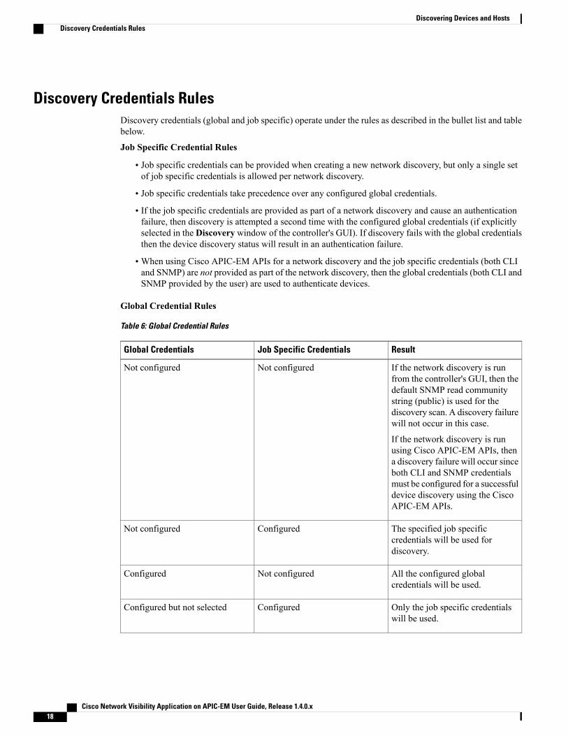
Discovery Credentials RulesDiscovery credentials (global and job specific) operate under the rules as described in the bullet list and tablebelow.
Job Specific Credential Rules
• Job specific credentials can be provided when creating a new network discovery, but only a single setof job specific credentials is allowed per network discovery.
• Job specific credentials take precedence over any configured global credentials.
• If the job specific credentials are provided as part of a network discovery and cause an authenticationfailure, then discovery is attempted a second time with the configured global credentials (if explicitlyselected in the Discovery window of the controller's GUI). If discovery fails with the global credentialsthen the device discovery status will result in an authentication failure.
• When using Cisco APIC-EM APIs for a network discovery and the job specific credentials (both CLIand SNMP) are not provided as part of the network discovery, then the global credentials (both CLI andSNMP provided by the user) are used to authenticate devices.
Global Credential Rules
Table 6: Global Credential Rules
ResultJob Specific CredentialsGlobal Credentials
If the network discovery is runfrom the controller's GUI, then thedefault SNMP read communitystring (public) is used for thediscovery scan. A discovery failurewill not occur in this case.
If the network discovery is runusing Cisco APIC-EM APIs, thena discovery failure will occur sinceboth CLI and SNMP credentialsmust be configured for a successfuldevice discovery using the CiscoAPIC-EM APIs.
Not configuredNot configured
The specified job specificcredentials will be used fordiscovery.
ConfiguredNot configured
All the configured globalcredentials will be used.
Not configuredConfigured
Only the job specific credentialswill be used.
ConfiguredConfigured but not selected
Cisco Network Visibility Application on APIC-EM User Guide, Release 1.4.0.x18
Discovering Devices and HostsDiscovery Credentials Rules

ResultJob Specific CredentialsGlobal Credentials
Only selected global credential willbe used.
Not configuredConfigured and selected
Both specified credentials (globaland job specific) will be used fordiscovery.
ConfiguredConfigured and selected
Discovery fails.
This scenario is onlypossible by API not fromthe controller GUI.
Note
Correct job specific credentialsconfigured
Configured, but wrong globalcredential IDs are mentioned in thediscovery POST REST API.
Discovery fails.
This scenario is onlypossible by API not fromthe controller GUI.
Note
Not configuredConfigured, but wrong globalcredential IDs are mentioned in thediscovery POST REST API.
Discovery Credentials CaveatsThe following are caveats for the Cisco APIC-EM discovery credentials:
• If a device credential changes in a network device or devices after Cisco APIC-EMdiscovery is completedfor that device or devices, any subsequent polling cycles for that device or devices will fail. To correctthis situation, an administrator has following options:
◦Start a new discovery scan with changed job specific credentials that matches the new devicecredential.
◦Edit the existing discovery by updating or modifying the global credentials, and then rerun thediscovery scan.
• If the ongoing discovery fails due to a device authentication failure (for example, the provided discoverycredential is not valid for the devices discovered by current discovery), then the administrator hasfollowing options:
◦Stop or delete the current discovery. Create one or more new network discovery jobs (either aCDPor Range discovery type) with a job specific credential that matches the device credential.
◦Create a new global credential and execute a new discovery selecting the correct global credential.
◦Edit an existing global credential and re-run the discovery.
• Deleting a global credential does not affect already discovered devices. These already discovered deviceswill not report an authentication failure.
• The Cisco APIC-EM provides a REST API which allows the retrieval of the list of managed networkdevices in the Cisco APIC-EM inventory. The purpose of this API is to allow an external application tosynchronize its own managed device inventory with the devices that have been discovered by the CiscoAPIC-EM. For example, for Cisco IWAN scenarios, Prime Infrastructure makes use of this API in order
Cisco Network Visibility Application on APIC-EM User Guide, Release 1.4.0.x 19
Discovering Devices and HostsDiscovery Credentials Caveats

to populate its inventory with the IWAN devices contained in the Cisco APIC-EM inventory in orderto provide monitoring of the IWAN solution.
Only the username is provided in clear text. SNMP community strings and passwordsare not provided in cleartext for security reasons.
Note
Configuring Global Discovery Credentials
Configuring CLI CredentialsCLI credentials are defined as preexisting device credentials that are common to most of the devices in anetwork. CLI credentials are used by the Cisco APIC-EM to authenticate and access the devices in a networkthat share this CLI credential when performing devices discoveries.
You configure the CLI global credentials in the CLI Credentials window or the Discovery window. Thisprocedure describes how to configure CLI global credentials in the CLI Credentials window.
You can configure up to five CLI credentials.Note
Figure 2: CLI Credentials Window
Before You Begin
You must have successfully deployed the Cisco APIC-EM and it must be operational.
Cisco Network Visibility Application on APIC-EM User Guide, Release 1.4.0.x20
Discovering Devices and HostsConfiguring Global Discovery Credentials
You must have administrator (ROLE_ADMIN) permissions and either access to all resources (RBAC scopeset to ALL) or an RBAC scope that contains all of the resources that you want to group. For example, to createa group containing a specific set of resources, you must have access to those resources (custom RBAC scopeset to all of the resources that you want to group).
For information about user permissions and RBAC scopes required to perform tasks using the Cisco APIC-EM,see "User Settings" in the chapter, "Configuring the Cisco APIC-EM Settings".
Step 1 In the Home window, click either admin or the Settings icon (gear) at the top right corner of the screen.Step 2 Click the Settings link from the drop-down menu.Step 3 In the Settings navigation pane, click CLI Credentials to view the CLI Credentials window.
In the CLI Credentials window, enter the appropriate CLI global credentials for the devices within your network ornetworks.
Step 4 Enter the CLI Credentials username in the Username field.Step 5 Enter the CLI Credentials password in the Password field.Step 6 Reenter the CLI Credentials password in the Confirm Password field to confirm the value that you just entered.Step 7 If your network devices have been configured with an enable password, then enter the CLI Credentials for the enable
password in the Enable Password field.Both the CLI credentials password and enable password are saved in the controller in encrypted form. Youcannot view these original passwords after you enter them.
Note
Step 8 If you entered an enable password in the Enable Password field, reenter it in the Confirm Enable Password field toconfirm the value that you just entered.
Step 9 In the CLI Credentials window, click Add to save the credentials to the Cisco APIC-EM database.
What to Do Next
Proceed to configure SNMP values for your network device discovery.
For a successful device discovery (with all the device information to be collected), CLI credentials (globaland/or job specific) should be configured using the controller. The global credentials for CLI and SNMP (v2cor v3) can be configured in theDiscovery Credentials windows (as described in this chapter) or theDiscoverywindow, and are used in addition to any job specific credentials (for CLI and SNMP) that are also configuredin the Discovery window.
Configuring SNMPYou configure SNMP for device discovery using the following Discovery Credentialswindows in the CiscoAPIC-EM GUI:
• SNMPv2c
• SNMPv3
• SNMP Properties
Cisco Network Visibility Application on APIC-EM User Guide, Release 1.4.0.x 21
Discovering Devices and HostsConfiguring SNMP

You can also configure SNMP for device discovery in the Discoverywindow of the controller's GUI. Forinformation about the procedures to configure SNMP for device discovery in the Discovery window, seethe Cisco Application Policy Infrastructure Controller Enterprise Module Configuration Guide.
Note
You can use SNMP and the existing security features in SNMP v3 to secure communications between thecontroller and the devices in your network. SNMP v3 provides both privacy (encryption) and authenticationcapabilities for these communications. If possible for your network, we recommend that you use SNMPv3with both privacy and authentication enabled.
Important
Configuring SNMPv2cYou configure SNMPv2c for device discovery in the SNMPv2c window in the Cisco APIC-EM GUI. TheSNMP values that you configure for SNMPv2c for the controller must match the SNMPv2c values that havebeen configured for your network devices.
You can configure up to five read community strings and five write community strings.Note
Figure 3: Configuring SNMPv2c
SNMP is an application-layer protocol that provides a message format for communication between SNMPmanagers and agents. SNMP provides a standardized framework and a common language used for themonitoring andmanagement of devices in a network. The different versions of SNMP are SNMPv1, SNMPv2,SNMPv2c, and SNMPv3.
Cisco Network Visibility Application on APIC-EM User Guide, Release 1.4.0.x22
Discovering Devices and HostsConfiguring SNMP
SNMPv2c is the community string-based administrative framework for SNMPv2. Community string is a typeof password, which is transmitted in clear text. SNMPv2c does not provide authentication or encryption(noAuthNoPriv level of security).
In addition to configuring SNMPv2c for device discovery in the controller, a "best effort" Cisco APIC-EMdiscovery is in place, meaning that devices having SNMP with Read-Only (RO) community string set to"public" will be discovered all the time irrespective of the configured SNMP Read/Write communitystring.
Note
Before You Begin
You must have successfully deployed the Cisco APIC-EM and it must be operational.
You must have your network's SNMP information available for this configuration procedure.
You must have administrator (ROLE_ADMIN) permissions and either access to all resources (RBAC scopeset to ALL) or an RBAC scope that contains all of the resources that you want to group. For example, to createa group containing a specific set of resources, you must have access to those resources (custom RBAC scopeset to all of the resources that you want to group).
For information about user permissions and RBAC scopes required to perform tasks using the Cisco APIC-EM,see "User Settings" in the chapter, "Configuring the Cisco APIC-EM Settings".
Step 1 In the Home window, click either admin or the Settings icon (gear) at the top right corner of the screen.Step 2 Click the Settings link from the drop-down menu.Step 3 In the Settings navigation pane, click SNMPv2c to view the SNMPv2c window.Step 4 In the SNMPv2c window, click Read Community.
Enter your Read Community values:
• Name/Description—Description of the Read-Only (RO) community string value and/or the device or devices thatare configured with it.
• Read Community—Read-Only community string value configured on devices that you need the controller toconnect to and access. This community string value must match the community string value pre-configured on thedevices that the controller will connect to and access.
• ConfirmRead Community—Reenter the Read-Only community string to confirm the value that you just entered.
If you are configuring SNMPv2c for your discovery, then configuringReadCommunity values is mandatory.Note
Step 5 Click Save to save your Read Community values.The Read Community values will appear in the table below.
Step 6 (Optional) In the SNMPv2c window, clickWrite Community.Enter yourWrite Community values:
• Name/Description—Description of theWrite community string value and/or the device or devices that are configuredwith it.
•Write Community—Write community string value configured on devices that you need the controller to connectto and access. This community string value must match the community string value pre-configured on the devicesthat the controller will connect to and access.
Cisco Network Visibility Application on APIC-EM User Guide, Release 1.4.0.x 23
Discovering Devices and HostsConfiguring SNMP

• Confirm Write Community—Reenter the Write community string to confirm the value that you just entered.
Step 7 (Optional) Click Save to save yourWrite Community values.TheWrite Community values will appear in the table below.
What to Do Next
If required for your SNMP configuration, proceed to configure either SNMPv3 or SNMP Properties usingthe GUI.
Configuring SNMPv3You configure SNMPv3 for device discovery in the SNMPv3 window in the Cisco APIC-EM GUI. TheSNMP values that you configure for SNMPv3 for the controller must match the SNMPv3 values that havebeen configured for your network devices. You can configure up to five SNMPv3 settings.
Figure 4: Configuring SNMPv3
SNMP is an application-layer protocol that provides a message format for communication between SNMPmanagers and agents. SNMP provides a standardized framework and a common language used for themonitoring andmanagement of devices in a network. The different versions of SNMP are SNMPv1, SNMPv2,SNMPv2c, and SNMPv3.
SNMPv3 provides secure access to devices by a combination of authenticating and encrypting frames overthe network. The following are supported SNMPv3 security models:
• Message integrity—Ensures that a packet has not been tampered with in-transit.
• Authentication—Determines the message is from a valid source
Cisco Network Visibility Application on APIC-EM User Guide, Release 1.4.0.x24
Discovering Devices and HostsConfiguring SNMP

• Encryption—Scrambles the packet contents to prevent it from being seen by unauthorized sources
SNMPv3 provides for both security models and security levels. A security model is an authentication strategythat is set up for a user and the role in which the user resides. A security level is the permitted level of securitywithin a security model. A combination of a security model and a security level determines which securitymechanism is employed when handling an SNMP packet.
The security level determines if an SNMP message needs to be protected from disclosure and if the messageneeds to be authenticated. The various security levels that exist within a security model are as follows:
• noAuthNoPriv—Security level that does not provide authentication or encryption
• AuthNoPriv—Security level that provides authentication but does not provide encryption
• AuthPriv—Security level that provides both authentication and encryption
The following table identifies what the combinations of security models and levels mean:
Table 7: SNMP Security Models and Levels
What HappensEncryptionAuthenticationLevelModel
Uses a communitystring match forauthentication.
NoCommunity StringnoAuthNoPrivv2c
Uses a usernamematch forauthentication.
NoUser NamenoAuthNoPrivv3
Providesauthentication basedon the Hash-BasedMessageAuthenticationCode(HMAC) MessageDigest 5 (MD5)algorithm or theHMACSecureHashalgorithm (SHA)
NoEither:
• HMAC-MD5
• HMAC-SHA
AuthNoPrivv3
Cisco Network Visibility Application on APIC-EM User Guide, Release 1.4.0.x 25
Discovering Devices and HostsConfiguring SNMP

What HappensEncryptionAuthenticationLevelModel
Providesauthentication basedon theHMAC-MD5or HMAC-SHAalgorithms.
Provides DataEncryption Standard(DES) 56-bitencryption inaddition toauthentication basedon the Cipher BlockChaining (CBC)DES (DES-56)standard orCBC-modeAES forencryption.
Either:
• CBC-DES
• CBC-AES-128
Either:
• HMAC-MD5
• HMAC-SHA
AuthPrivv3
Before You Begin
You must have successfully deployed the Cisco APIC-EM and it must be operational.
You must have your network's SNMP information available for this configuration procedure.
You must have administrator (ROLE_ADMIN) permissions and either access to all resources (RBAC scopeset to ALL) or an RBAC scope that contains all of the resources that you want to group. For example, to createa group containing a specific set of resources, you must have access to those resources (custom RBAC scopeset to all of the resources that you want to group).
For information about user permissions and RBAC scopes required to perform tasks using the Cisco APIC-EM,see "User Settings" in the chapter, "Configuring the Cisco APIC-EM Settings".
With SNMPv3, passwords (or passphrases) must be at least 8 characters in length (minimum). Additionally,for several Cisco Wireless LAN controllers, passwords (or passphrases) must be at least 12 characters inlength (minimum). Failure to ensure these required minimum character lengths for the passwords willresult in devices not being discovered, monitored, and/or managed by the controller.
Note
Step 1 In the Home window, click either admin or the Settings icon (gear) at the top right corner of the screen.Step 2 Click the Settings link from the drop-down menu.Step 3 In the Settings navigation pane, click SNMPv3 to view the SNMPv3 window.
If you use SNMPv3 in your network to monitor and manage devices, then configure the SNMPv3 values for discoveryfor your network.
Step 4 In the SNMPv3 window, enter a Username value and choose aMode from the drop down menu.The followingMode options are available:
Cisco Network Visibility Application on APIC-EM User Guide, Release 1.4.0.x26
Discovering Devices and HostsConfiguring SNMP

• AuthPriv
• AuthNoPriv
• NoAuthNoPriv
Subsequent SNMPv3 configuration options might or might not be available depending upon your selection forthis step.
Note
Step 5 If you selected AuthPriv or AuthNoPriv as aMode option, then choose an Authentication type from the drop downmenu and enter an authentication password.The following Authentication options are available:
• SHA—Authentication based on the Hash-Based Message Authentication Code (HMAC), Secure Hash algorithm(SHA) algorithm
•MD5—Authentication based on the Hash-BasedMessage Authentication Code (HMAC),Message Digest 5 (MD5)algorithm
Step 6 If you selectedAuthPriv as aMode option, then choose a Privacy type from the drop down menu and enter a SNMPv3privacy password.The SNMPv3 privacy password is used to generate the secret key used for encryption of messages exchanged withdevices that support DES or AES128 encryption.
The following Privacy type options are available:
• DES—Data Encryption Standard (DES) 56-bit encryption in addition to authentication based on the Cipher BlockChaining (CBC) DES (DES-56) standard.
• AES128—Cipher Block Chaining (CBC) mode AES for encryption.
Step 7 Click Save to save your SNMPv3 configuration values.The SNMPv3 configured values will appear in the table below.
What to Do Next
If required for your SNMP configuration, proceed to configure either SNMPv2c or SNMP Properties usingthe GUI.
Cisco Network Visibility Application on APIC-EM User Guide, Release 1.4.0.x 27
Discovering Devices and HostsConfiguring SNMP
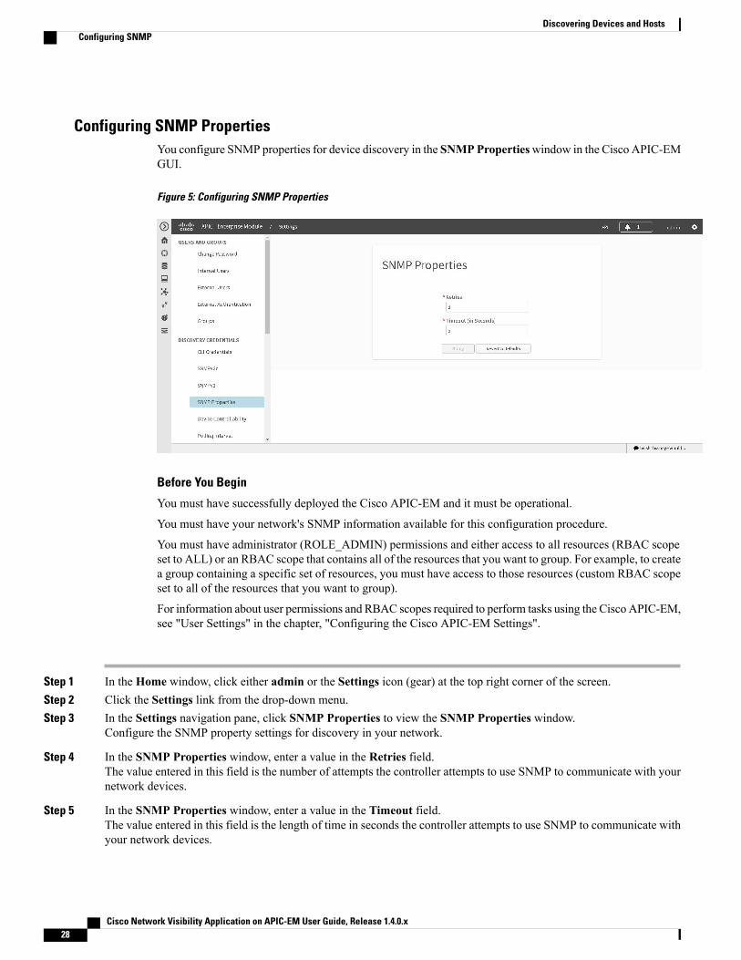
Configuring SNMP PropertiesYou configure SNMP properties for device discovery in the SNMPPropertieswindow in the Cisco APIC-EMGUI.
Figure 5: Configuring SNMP Properties
Before You Begin
You must have successfully deployed the Cisco APIC-EM and it must be operational.
You must have your network's SNMP information available for this configuration procedure.
You must have administrator (ROLE_ADMIN) permissions and either access to all resources (RBAC scopeset to ALL) or an RBAC scope that contains all of the resources that you want to group. For example, to createa group containing a specific set of resources, you must have access to those resources (custom RBAC scopeset to all of the resources that you want to group).
For information about user permissions and RBAC scopes required to perform tasks using the Cisco APIC-EM,see "User Settings" in the chapter, "Configuring the Cisco APIC-EM Settings".
Step 1 In the Home window, click either admin or the Settings icon (gear) at the top right corner of the screen.Step 2 Click the Settings link from the drop-down menu.Step 3 In the Settings navigation pane, click SNMP Properties to view the SNMP Properties window.
Configure the SNMP property settings for discovery in your network.
Step 4 In the SNMP Properties window, enter a value in the Retries field.The value entered in this field is the number of attempts the controller attempts to use SNMP to communicate with yournetwork devices.
Step 5 In the SNMP Properties window, enter a value in the Timeout field.The value entered in this field is the length of time in seconds the controller attempts to use SNMP to communicate withyour network devices.
Cisco Network Visibility Application on APIC-EM User Guide, Release 1.4.0.x28
Discovering Devices and HostsConfiguring SNMP

Step 6 Click Apply to save your SNMP configuration values.You can also click Revert to Defaults to revert to the SNMP property default values. The following are the SNMPproperty default values:
• Retries—3
• Timeout—5
What to Do Next
If required for your SNMP configuration, proceed to configure either SNMPv2c or SNMPv3 using the GUI.
Enabling Device ControllabilityYou can enable device controllability in the Device Controllability window of the Cisco APIC-EM GUI.When you enable device controllability, the controller performs two actions during a discovery:
• The controller automatically configures (applies) the SNMP credentials that you entered using thecontroller's GUI on any network devices without SNMP credentials (SNMPv2c and/or SNMPv3).
• The controller automatically enables IP device tracking (IPDT) on any network devices where it issupported but not enabled in your network.
IPDT is enabled only on devices that are identified as Access role in Device Inventory window. The devicedoes not need to be in aManaged state to have IPDT enabled. The IPDT configuration is applied to devicesas long as Device Inventory has the device's software version, role, and so on.
Cisco Network Visibility Application on APIC-EM User Guide, Release 1.4.0.x 29
Discovering Devices and HostsEnabling Device Controllability

The device controllability functionality depends upon whether the CLI credentials provided by the userpermits the controller to log into the device in enable mode (privilege level 15 for Cisco IOS devices).
Note
Figure 6: Enabling Device Controllability
Before You Begin
You must have successfully deployed the Cisco APIC-EM and it must be operational.
You must have administrator (ROLE_ADMIN) permissions and either access to all resources (RBAC scopeset to ALL) or an RBAC scope that contains all of the resources that you want to group. For example, to createa group containing a specific set of resources, you must have access to those resources (custom RBAC scopeset to all of the resources that you want to group).
For information about user permissions and RBAC scopes required to perform tasks using the Cisco APIC-EM,see "User Settings" in the chapter, "Configuring the Cisco APIC-EM Settings".
Step 1 In the Home window, click either admin or the Settings icon (gear) at the top right corner of the screen.Step 2 Click the Settings link from the drop-down menu.Step 3 In the Settings navigation pane, click Device Controllability to view the Device Controllability window.Step 4 (Optional) Click Yes for SNMP Autoconfig to automatically to enable this feature.
Clicking Yes for SNMP Autoconfig automatically applies the SNMP credentials you configured using the controller'sGUI to any devices in your network without an SNMP configuration.
Step 5 (Optional) Click Yes for IPDT Autoconfig to enable this feature.Clicking Yes for IPDT Autoconfig automatically enables IP device tracking (IPDT) on any devices in your networkwhere it is supported but not enabled.
Step 6 Click Save to save your configuration.
Cisco Network Visibility Application on APIC-EM User Guide, Release 1.4.0.x30
Discovering Devices and HostsEnabling Device Controllability

What to Do Next
If you have not already done so, configure SNMP in either the Discovery window or the appropriate CLICredentials window for SNMP in Settings.
Configuring the Polling IntervalYou can configure the polling interval for inventory data collection for devices managed by Cisco APIC-EM.This polling interval configuration will be used for all managed devices, unless the polling interval of a deviceis updated specifically in the Inventory page.
You configure the polling interval in the Polling Interval Settings window of the Cisco APIC-EM GUI.
The polling interval value that you configure is a global value used for performing periodic inventory datacollection, it is not used for discovering the device.
Note
Figure 7: Polling Interval Window
Before You Begin
You must have successfully deployed the Cisco APIC-EM and it must be operational.
You must have administrator (ROLE_ADMIN) permissions and either access to all resources (RBAC scopeset to ALL) or an RBAC scope that contains all of the resources that you want to group. For example, to createa group containing a specific set of resources, you must have access to those resources (custom RBAC scopeset to all of the resources that you want to group).
Cisco Network Visibility Application on APIC-EM User Guide, Release 1.4.0.x 31
Discovering Devices and HostsConfiguring the Polling Interval

For information about user permissions and RBAC scopes required to perform tasks using the Cisco APIC-EM,see "User Settings" in the chapter, "Configuring the Cisco APIC-EM Settings".
Step 1 In the Home window, click either admin or the Settings icon (gear) at the top right corner of the screen.Step 2 Click the Settings link from the drop-down menu.Step 3 In the Settings navigation pane, click Polling Interval to view the Polling Interval window.Step 4 Enter a polling interval value in minutes in the Polling Interval field.
The default polling interval is 25 minutes for device discovery by the controller.
Step 5 Click Save to save your polling interval configuration.
Cisco Network Visibility Application on APIC-EM User Guide, Release 1.4.0.x32
Discovering Devices and HostsConfiguring the Polling Interval

Performing Discovery
Performing Discovery Using CDPYou can discover devices and hosts using CDP.
Figure 8: Discovery Using CDP
Figure 9: Discovery Using CDP
Cisco Network Visibility Application on APIC-EM User Guide, Release 1.4.0.x 33
Discovering Devices and HostsPerforming Discovery

Before You Begin
You must have administrator (ROLE_ADMIN) permissions and access to all devices (RBAC Scope set toALL) to perform this procedure.
CDP must be enabled on the devices in order for them to be discovered.
Your devices must have the required device configurations, as described in Device Configuration Prerequisites,on page 11.
Step 1 From the Navigation pane, click Discovery.Step 2 From the Discovery window, click + New Discovery.
The New Discovery pane appears.
Step 3 In the Discovery Name field, enter a unique name for the discovery job.Step 4 In the IP Ranges area, configure the following settings:
a) In the Type field, choose CDP.b) In the IP Address field, enter a seed IP address for the Cisco APIC-EM to use to start the discovery scan.c) (Optional) In the Subnet Filter field, enter the IP address or subnet and click + the plus sign..
You can enter the address as an individual IP address (x.x.x.x) or as a classless inter-domain routing (CIDR) address(x.x.x.x/y) where x.x.x.x refers to the IP address and y refers to the subnet mask. The subnet mask can be a value from0 to 32.
Repeat this step to exclude multiple subnets from the discovery job.
d) (Optional) In the CDP Level field, enter the number of hops from the seed device that you want to scan.
Cisco Network Visibility Application on APIC-EM User Guide, Release 1.4.0.x34
Discovering Devices and HostsPerforming Discovery Using CDP

Valid values are from 1 to 16. The default value is 16. For example, CDP level 3 means that CDP will scan up tothree hops from the seed device.
Step 5 Open the Credentials area and configure the credentials that you want to use for the discovery job.You can configure credentials to be used for the current discovery job, or you can check the Save as global settingscheckbox to save the credentials for future discovery jobs.
a) Make sure that any global credentials that you want to use are checked. If you do not want to use a credential, removeit by clicking the check mark.
b) To add additional credentials, click + Add Credentials, complete the fields in the following tables for the credentialsthat you want to use, and click Add.With the SNMP Autoconfig option enabled under Settings > Device Controllability, Cisco APIC-EM configuresdevices that do not have SNMP credentials with the SNMP credentials set in Global Settings or in the specificdiscovery job, whichever one takes priority.
Discovery requires the correct SNMP Read Only (RO) community string. If an SNMP RO community string is notprovided, as a best effort, discovery uses the default SNMP RO community string, "public."
CLI credentials are not required to discover hosts; hosts are discovered through the devices that they areconnected to.
Note
Table 8: CLI Credentials
DescriptionField
Username that is used to log into the command lineinterface (CLI) of the devices in your network.
Username
Password that is used to log into the CLI of the devices inyour network.
For security reasons, you must enter the password againas confirmation.
Passwords are encrypted for security reasons and are notdisplayed in the configuration.
Password
Confirm Password
Password used to move to a higher privilege level in theCLI.
For security reasons, you must enter the enable passwordagain as confirmation.
Passwords are encrypted for security reasons and are notdisplayed in the configuration.
Enable Password
Confirm Enable Password
Cisco Network Visibility Application on APIC-EM User Guide, Release 1.4.0.x 35
Discovering Devices and HostsPerforming Discovery Using CDP

Table 9: SNMP v2c Credentials
DescriptionField
SNMP read-only (RO) community string configuration, which comprises the following fields:
• Name/Description—Name or description of the SNMP v2c settings that you are adding.
• Read Community and Confirm Read Community—Read-only community stringpassword used only to view SNMP information on the device.
Passwords are encrypted for security reasons and are not displayed in the configuration.Note
To enable discovery on the network devices, configure the network device's IP hostaddress as the client address.
Note
Read
SNMP read-write (RW) community string configuration, which comprises the following fields:
• Name/Description—Name or description of the SNMP v2c settings that you are adding.
•Write Community and Confirm Write Community—Read/Write community stringpassword used to view and make changes to SNMP information on the device.
Passwords are encrypted for security reasons and are not displayed in the configuration.Note
To enable discovery on the network devices, configure the network device's host IPaddress as the client IP address.
Note
Write
Table 10: SNMP v3 Credentials
DescriptionField
Username associated with the SNMPv3 settings.Username
Specifies the security level that an SNMP message requires and whether the message needs tobe authenticated. Choose one of the following modes:
• noAuthNoPriv—Security level that does not provide authentication or encryption
• AuthNoPriv—Security level that provides authentication but does not provide encryption
• AuthPriv—Security level that provides both authentication and encryption
Mode
SNMPv3 password used for gaining access to information from devices that use SNMPv3.
Passwords are encrypted for security reasons and are not displayed in the configuration.Note
Auth Password
Cisco Network Visibility Application on APIC-EM User Guide, Release 1.4.0.x36
Discovering Devices and HostsPerforming Discovery Using CDP

DescriptionField
Specifies the authentication type to be used.
• SHA—Authentication based on the Hash-BasedMessage Authentication Code (HMAC),Secure Hash algorithm (SHA) algorithm
•MD5—Authentication based on the Hash-BasedMessage Authentication Code (HMAC),Message Digest 5 (MD5) algorithm
• None—No authentication
Auth Type
SNMPv3 privacy password is used to generate the secret key used for encryption of messagesexchanged with devices that support DES or AES128 encryption.
Passwords are encrypted for security reasons and are not displayed in the configuration.Note
Privacy Password
Specifies the privacy type:
• DES—Data Encryption Standard (DES) 56-bit encryption in addition to authenticationbased on the Cipher Block Chaining (CBC) DES (DES-56) standard.
• AES128—Cipher Block Chaining (CBC) mode AES for encryption.
• None—No privacy
Privacy Type
Table 11: SNMP Properties
DescriptionField
Number of attempts to connect to the device. Valid values are from 0 to 4 attempts.Retries
Number of seconds the controller waits when trying to establish a connection with a devicebefore timing out. Valid values are from 5 to 120 seconds in intervals of 5 seconds.
Timeout (inSeconds)
Step 6 (Optional) To configure the protocols to be used to connect with devices, open theAdvanced area and do the following:a) Click the protocols that you want to use. A green checkmark indicates that the protocol is selected.
Valid protocols are SSH (default) and Telnet.
b) Drag and drop the protocols in the order that you want them to be used.
Step 7 Click Start Discovery.The Discoveries window displays the results of your scan.
TheDiscovery Details pane shows the status (active or inactive) and the discovery configuration. TheDiscovery Devicespane displays the host names, IP addresses, and status of the discovered devices for the selected discovery.
Cisco Network Visibility Application on APIC-EM User Guide, Release 1.4.0.x 37
Discovering Devices and HostsPerforming Discovery Using CDP

Performing Discovery Using an IP Address RangeYou can discover devices using an IP address range.
Figure 10: Discovery Using IP Address Range
Before You Begin
You must have administrator (ROLE_ADMIN) permissions and access to all devices (RBAC Scope set toALL) to perform this procedure.
Your devices must have the required device configurations, as described in Device Configuration Prerequisites,on page 11.
Step 1 From the Navigation pane, click Discovery.Step 2 From the Discovery window, click + New Discovery.
The New Discovery pane appears.
Step 3 In the Discovery Name field, enter a unique name for the discovery job.Step 4 If the Discovery Details pane does not appear, click Add New.Step 5 In the Discovery Name field, enter a unique name for this discovery.Step 6 In the IP Ranges area, do the following:
a) From the Discovery Type field, choose Range for the discovery scan type.b) In the IP Address field, enter the beginning and ending IP addresses (IP range) for the devices being discovered and
click + (the plus sign).You can enter a single IP address range or multiple IP addresses for the discovery scan.
Cisco Network Visibility Application on APIC-EM User Guide, Release 1.4.0.x38
Discovering Devices and HostsPerforming Discovery Using an IP Address Range

c) Repeat Step b to enter additional IP address ranges.
Step 7 Open the Credentials area and configure the credentials that you want to use for the discovery job.You can configure credentials to be used for the current discovery job, or you can check the Save as global settingscheckbox to save the credentials for future discovery jobs.
a) Make sure that any global credentials that you want to use are checked. If you do not want to use a credential, removeit by clicking the check mark.
b) To add additional credentials, click + Add Credentials, complete the fields in the following tables for the credentialsthat you want to use, and click Save.With the SNMP Autoconfig option enabled under Settings > Device Controllability, Cisco APIC-EM configuresdevices that do not have SNMP credentials with the SNMP credentials set in Global Settings or in the specificdiscovery job, whichever one takes priority.
Discovery requires the correct SNMP Read Only (RO) community string. If an SNMP RO community string is notprovided, as a best effort, discovery uses the default SNMP RO community string, "public."
CLI credentials are not required to discover hosts; hosts are discovered through the devices that they areconnected to.
Note
Table 12: CLI Credentials
DescriptionField
Username that is used to log into the command lineinterface (CLI) of the devices in your network.
Username
Password that is used to log into the CLI of the devices inyour network.
For security reasons, you must enter the password againas confirmation.
Passwords are encrypted for security reasons and are notdisplayed in the configuration.
Password
Confirm Password
Password used to move to a higher privilege level in theCLI.
For security reasons, you must enter the enable passwordagain as confirmation.
Passwords are encrypted for security reasons and are notdisplayed in the configuration.
Enable Password
Confirm Enable Password
Cisco Network Visibility Application on APIC-EM User Guide, Release 1.4.0.x 39
Discovering Devices and HostsPerforming Discovery Using an IP Address Range

Table 13: SNMP v2c Credentials
DescriptionField
SNMP read-only (RO) community string configuration, which comprises the following fields:
• Name/Description—Name or description of the SNMP v2c settings that you are adding.
• Read Community andConfirm Read Community—Read-only community string usedonly to view SNMP information on the device.
Passwords are encrypted for security reasons and are not displayed in the configuration.Note
To enable discovery on the network devices, configure the network device's IP hostaddress as the client address.
Note
Read
SNMP read-write (RW) community string configuration, which comprises the following fields:
• Name/Description—Name or description of the SNMP v2c settings that you are adding.
•Write Community and Confirm Write Community—Read/Write community stringused to view and make changes to SNMP information on the device.
Passwords are encrypted for security reasons and are not displayed in the configuration.Note
To enable discovery on the network devices, configure the network device's IP hostaddress as the client address.
Note
Write
Table 14: SNMP v3 Credentials
DescriptionField
Username associated with the SNMPv3 settings.Username
Specifies the security level that an SNMP message requires and whether the message needs tobe authenticated. Choose one of the following modes:
• noAuthNoPriv—Security level that does not provide authentication or encryption
• AuthNoPriv—Security level that provides authentication but does not provide encryption
• AuthPriv—Security level that provides both authentication and encryption
Mode
SNMPv3 password used for gaining access to information from devices that use SNMPv3.Auth Password
Specifies the authentication type to be used.
• SHA—Authentication based on the Hash-BasedMessage Authentication Code (HMAC),Secure Hash algorithm (SHA) algorithm
•MD5—Authentication based on the Hash-BasedMessage Authentication Code (HMAC),Message Digest 5 (MD5) algorithm
• None—No authentication
Auth Type
Cisco Network Visibility Application on APIC-EM User Guide, Release 1.4.0.x40
Discovering Devices and HostsPerforming Discovery Using an IP Address Range

DescriptionField
SNMPv3 privacy password is used to generate the secret key used for encryption of messagesexchanged with devices that support DES or AES128 encryption.
Privacy Password
Specifies the privacy type:
• DES—Data Encryption Standard (DES) 56-bit encryption in addition to authenticationbased on the Cipher Block Chaining (CBC) DES (DES-56) standard.
• AES128—Cipher Block Chaining (CBC) mode AES for encryption.
• None—No privacy
Privacy Type
Table 15: SNMP Properties
DescriptionField
Number of attempts to connect to the device. Valid values are from 0 to 4 attempts.Retries
Number of seconds the controller waits when trying to establish a connection with a devicebefore timing out. Valid values are from 5 to 120 seconds in intervals of 5 seconds.
Timeout (inSeconds)
Step 8 Click Start Discovery.The Discoveries window displays the results of your scan.
TheDiscovery Details pane shows the status (active or inactive) and the discovery configuration. TheDiscovery Devicespane displays the host names, IP addresses, and status of the discovered devices for the selected discovery.
Step 9 (Optional) To configure the protocols to be used to connect with devices, open theAdvanced area and do the following:a) Click the protocols that you want to use. A green checkmark indicates that the protocol is selected.
Valid protocols are SSH (default) and Telnet.
b) Drag and drop the protocols in the order that you want them to be used.
Copying a Discovery JobYou can copy a discovery job and retain all of the information defined for the job, except the SNMP and CLIcredentials. The SNMP and CLI credentials are included in the copy only if you used global credentials (savedin Settings) for the original job. If you defined specific (one-time only) SNMP and CLI credentials for theoriginal job, the credentials are not copied.
Cisco Network Visibility Application on APIC-EM User Guide, Release 1.4.0.x 41
Discovering Devices and HostsCopying a Discovery Job

Before You Begin
You have created at least one discovery scan.
Step 1 From the Navigation pane, click Discovery.Step 2 From the Discoveries pane, select the discovery job.Step 3 From the Discovery Details pane, click Copy.
The discovery job is copied, and the new job is named Copy of Discovery_Job.
Step 4 (Optional) Change the name of the discovery job.Step 5 Define or update the SNMP and CLI credentials and any other parameters for the discovery job.
Stopping and Starting a Discovery JobYou can stop a discovery job that is in progress, and restart it.
Before You Begin
You must have administrator (ROLE_ADMIN) permissions and access to all devices (RBAC Scope set toALL) to perform this procedure.
Step 1 From the Navigation pane, click Discovery.Step 2 To stop an active discovery job, do the following:
a) From the Discoveries pane, select the discovery job.b) From the Discovery Details pane, click Stop.c) Click OK to confirm that you want to stop the discovery job.
Step 3 To restart an inactive discovery, do the following:a) From the Discoveries pane, select the discovery job.b) From the Discovery Details pane, click Start.
Deleting a Discovery JobYou can delete a discovery job whether it is active or inactive.
Cisco Network Visibility Application on APIC-EM User Guide, Release 1.4.0.x42
Discovering Devices and HostsStopping and Starting a Discovery Job

Before You Begin
You must have administrator (ROLE_ADMIN) permissions and access to all devices (RBAC Scope set toALL) to perform this procedure.
Step 1 From the Navigation pane, click Discovery.Step 2 From the Discoveries pane, select the discovery job that you want to delete.Step 3 From the Discovery Details pane, click Delete.Step 4 Click OK to confirm that you want to delete the discovery.
Understanding the Discovery ResultsThe Discovery Results pane provides information about the selected scan.
To access the Discovery Results pane, do the following:
1 From the Navigation pane, click Discovery.
2 From the Discoveries pane, select the discovery job that you want to display.
Cisco Network Visibility Application on APIC-EM User Guide, Release 1.4.0.x 43
Discovering Devices and HostsUnderstanding the Discovery Results

The Discovery Results pane appears. See the following figures and table for information.
Figure 11: Discovery Results Window—List
Figure 12: Discovery Results Window—Chart
Cisco Network Visibility Application on APIC-EM User Guide, Release 1.4.0.x44
Discovering Devices and HostsUnderstanding the Discovery Results

Table 16: Discovery Pane
DescriptionName
Displays the following information:
• Name of the discovery job.
• Status of the discovery job.
• Number of devices discovered.
From this area, you can delete, clone, edit, or start a discovery job.
Discovery Identificationand Action Area
Open this area to display detailed information about the parameters that were usedto perform the discovery, including the CDP level (if used), protocol order, retrycount, timeout value, IP address (seed) or range of IP addresses used, and IPaddress filter list.
Discovery Details area
Open this area to display the credentials used in the discovery job and identifiesthem as either global or job-specific.
Credentials area
Open this area to display a table showing information about each iteration of thediscovery job, including the job number, its status, an option to view the devicesdiscovered, and the duration of the job. Clicking the View link in the Devicescolumn opens the Devices pane.
Last Runs area
(Shown when you open theLast Runs area and click theView link in theDevicescolumn.)
The devices pane displays the results of the device discovery in two forms:
• List—For each device, provides the following information:
◦IP address—IP addresses of the devices that Cisco APIC-EMdiscovered or attempted to discover.
◦Device name—Name of the device, if available.
◦Status—Status of the discovery for the device. Possible states aresuccess, unreachable, failure, not tried, or unavailable.
◦Internet Control Message Protocol (ICMP)—Status of the ICMPfor the device.
◦SNMP—Status of theCisco APIC-EM's use of the SNMP settings togather SNMP information from the device.
◦CLI—Status of theCisco APIC-EM's use of the CLI username andpasswords to gather information from the device.
• Chart—Displays a circle graph showing the proportional representation ofsuccessful versus failed discovered devices.
Devices pane
Cisco Network Visibility Application on APIC-EM User Guide, Release 1.4.0.x 45
Discovering Devices and HostsUnderstanding the Discovery Results

Cisco Network Visibility Application on APIC-EM User Guide, Release 1.4.0.x46
Discovering Devices and HostsUnderstanding the Discovery Results

C H A P T E R 5Managing Devices and Hosts
• Managing Your Device Inventory, page 47
• Managing Your Host Inventory, page 76
Managing Your Device InventoryThe Device Inventory window displays the results of the discovery scan. To access the Discovery window,from the Navigation pane, click Device Inventory.
Figure 13: Device Inventory Window
The information that is displayed depends on the Layout that you selected.Note
Cisco Network Visibility Application on APIC-EM User Guide, Release 1.4.0.x 47

After the initial discovery, network devices are polled every 30 minutes. Polling occurs for each device, link,host, and interface. Only devices that have been active for less than a day are displayed. This prevents anystale device data from being displayed. On average, polling 500 devices takes approximately 20 minutes.
For information about the actions that you can perform from the Device Inventory window, see DeviceInventory Tasks, on page 54.
The following table describes the main elements in the Device Inventory table.
DescriptionWindow Element
Allows you to select devices to perform tasks.
When you select a device, the action buttons appear above the Device Inventorytable. For information about these buttons and the actions that you can performwith them, see Device Inventory Tasks, on page 54.
Device Selection checkboxes
Allows you to refine the list of devices that are displayed in the table by name,location tag, and IP address.
To remove filters, click Clear Filters.
Filters
Allows you to choose from three predefined layouts or a customized layout:
• Status—Layout shows the device name, IP address, state of the device, howlong it has been up, and the last time it was updated.
• Hardware—Layout shows the device name, IP address, device family,platform, serial number, MAC address, and role, along with its IOS/firmwareversion and a link to its configuration file.
• Tagging—Layout shows the device name, IP address, MAC address, devicerole, location, and tags.
• Customize—Layout shows the information in the columns that you haveselected to display.
For descriptions of the columns of information that you can display, see the DeviceInventory Information table below.
Layout
Below the Device Inventory table, you can adjust the number of devices displayed in the table (10, 25, 50,100), and you can click First, Previous, Next, Last, or the page number to navigate through the table.
Device Inventory InformationTheDevice Inventory table displays the following information for each discovered device. All of the columns,except the Config column, support sorting. Clicking on the column header sorts the rows in an ascendingorder. Clicking on the column header again sorts the rows in descending order.
For more information, see the Cisco Application Policy Infrastructure Controller Enterprise ModuleConfiguration Guide.
Cisco Network Visibility Application on APIC-EM User Guide, Release 1.4.0.x48
Managing Devices and HostsDevice Inventory Information

Table 17: Device Inventory Information
DescriptionColumn Name
State of the device.
• Connecting—Controller is connecting to thedevice.
• Reachable:
◦Discovered—Controller has connected tothe device and is able to execute Ciscocommands using the CLI .
◦Failure—Controller has connected to thedevice, but is unable to execute Ciscocommands using the CLI. This statususually indicates that the device is not aCisco device.
• Authentication Failed—Controller hasconnected to the device but is unable todetermine what type of device it is. This devicestatus also usually indicates that the device isnot a Cisco device.
• Unreachable—Controller is unable to connectto the device.
If credentials are not provided at thetime a discovery request is made orearlier, then the device status could bedisplayed as "Not reachable." Youneed to perform a new discovery withthe correct credentials.
Note
Device Status
Cisco Network Visibility Application on APIC-EM User Guide, Release 1.4.0.x 49
Managing Devices and HostsDevice Inventory Information

DescriptionColumn Name
Name of the device. Click the device name to displaythe Device Overview dialog box with the followinginformation:
• Device serial number
• Device IP address
• MAC address
• Cisco OS version
• Up time
• Product ID
• Vendor
• Memory size
The device name appears red for any devicewhose inventory has not been updated formore than 30 minutes.
Note
The Device Overview dialog box also includes anInterfaces tab with the following interface data:
• Status—Up or down
• Interface name—Name of the interface.
• MAC address—MAC address of the interface.
Device Name
MAC address of the device.MAC Address
IP address of the device.IP Address
Cisco IOS software currently running on the device.IOS/Firmware
Cisco product part number.Platform
Cisco device serial number.Serial Number
Period of time that the device has been up andrunning.
Up Time
Click View to display detailed configurationinformation similar to the CLI show running-configcommand output.
This feature is not supported for accesspoints and wireless LAN controllers,therefore configuration data is not returnedfor these device types.
Note
Config
Cisco Network Visibility Application on APIC-EM User Guide, Release 1.4.0.x50
Managing Devices and HostsDevice Inventory Information

DescriptionColumn Name
Role assigned to each discovered device during thescan process. The device role is used to identify andgroup devices according to their responsibilities andplacement within the network. If the controller isunable to determine a device role, it sets the devicerole as unknown.
The controller can change the device role asthe network topology changes, but if youmanually change the device role, then therole will not change as the network topologychanges.
Note
If desired, you can use the drop-down list in thiscolumn to change the assigned device role. Thefollowing device roles are available:
• Unknown
• Access
• Core
• Distribution
• Border Router
Device Role
Cisco Network Visibility Application on APIC-EM User Guide, Release 1.4.0.x 51
Managing Devices and HostsDevice Inventory Information

DescriptionColumn Name
Tag that you can apply to a device to denote itsgeographic location. By applying the same tag toseveral devices, you can group them based on acommon attribute. The Device Inventory windowand Topology window support location tags.
Use the following guidelines when creating locationtags:
• Location tag information is maintained on thecontroller only and not deployed to or dirivedfrom the device itself.
• A location defined on the controller is not the"civic-location" property that some devicessupport.
• You cannot create, use, or search for locationtags in the Topology window.
• Location tags cannot be attached to hosts.
• You can apply only one location tag to a device.However, you can use both a location tag anda device tag together.
For information about adding location tags, seeAdding or Removing Location Tags, on page 65.
Along with the location tag, you can add ageographical marker on a world map to a device. Forinformation, see Adding or Changing a LocationMarker, on page 67.
Location
Tag assigned to devices to identify them by a commonattribute. For example, you can create a tag and useit to group devices based on a platform ID or CiscoIOS release.
A number in the Tag column indicates how manytags have been applied to that device.
You are permitted to use both a location tagand a device tag together.
Note
For information about adding or removing devicetags, see Adding or Removing a Device Tag in DeviceInventory, on page 63.
For information about deleting a tag from thecontroller database, see Deleting a Tag, on page 68.
Device Tag
Cisco Network Visibility Application on APIC-EM User Guide, Release 1.4.0.x52
Managing Devices and HostsDevice Inventory Information

DescriptionColumn Name
Tag applied to a group of devices that will share thesame policy.
After applying a policy tag, you need to configure thepolicies that will be applied to the devices with thesame policy tag. For information about configuringQoS policies, see the Cisco EasyQoS Application forAPIC-EM User Guide.
Policy Tag
Date and time that the device was last scanned andthe controller database was updated.
Last Updated Time
Group of related devices, as follows:
• Cisco Interfaces and Modules
• Routers
• Switches and Hubs
• Third Party Device
• Unsupported Cisco Device
• Wireless Controller
Device Family
Series number of the device, for example, CiscoCatalyst 4500 Series Switches.
Device Series
Status of the last discovery scan for the device:
•Managed—Device is in a fully managed state.
• Partial Collection Failure—Device is in apartial collected state and not all the inventoryinformation has been collected.Move the cursorover the Information (i) icon to displayadditional information about the failure.
• Unreachable—Due to device connectivityissues, the device could not be reached and noinventory information was collected. Thiscondition can occur when periodic collectionhappens.
•Wrong Credentials—If the device credentialsare changed after adding the device to theinventory, this condition is noted.
• In Progress—Inventory collection is occurring.
Last Inventory Collection Status
Cisco Network Visibility Application on APIC-EM User Guide, Release 1.4.0.x 53
Managing Devices and HostsDevice Inventory Information

Device Inventory TasksThe actions that you can perform from the Device Inventory window depend on the layout that you choose.When you select one or more devices, you can click any of the following buttons to perform the correspondingaction.
Table 18: Device Inventory Buttons
ActionButton
Allows you to discover a specific device and add itto your inventory. If authentication of the device failsdue to invalid credentials, the device enters thecollection failure state. For information, see Addinga Device Manually, on page 55.
Add Device
Sets the location of the devices associated with alocation tag on a geographical map. For information,see Adding or Changing a LocationMarker, on page67.
Set Location
Groups devices according to common attributes. Forinformation, see Adding or Removing a Device Tagin Device Inventory, on page 63.
Set Device Tags
Groups devices so that you can deploy the same QoSpolicy to those devices at the same time. Forinformation, see Adding or Removing a Policy Tagin Device Inventory, on page 64.
Set Policy Tag
Deletes the selected devices from inventory. Forinformation, see Deleting a Device, on page 58.
Delete
Changes the credentials of the selected devices. Infuture discoveries, these credentials are used for theselected devices instead of the global or discoveryjob-specific credentials. For information, see UpdatingDevice Credentials, on page 70
Update Credentials
You can update the polling interval of selecteddevices. These device-specific settings override theglobal and job-specific settings for the selecteddevices. For information, see Updating a Device'sPolling Interval, on page 74.
Update Polling Interval
Immediately polls the selected device for updateddevice information and status. For information, seeResynchronizing Device Information, on page 73.
Resync (Resynchronize Devices)
Cisco Network Visibility Application on APIC-EM User Guide, Release 1.4.0.x54
Managing Devices and HostsDevice Inventory Tasks

ActionButton
Sends CLI commands to the selected devices usingAPI commands. Currently, show and other read-onlycommands are permitted. For information, seeRunning Commands on Devices, on page 74.
Command Runner
Adding a Device ManuallyYou can manually add a device to your inventory.
Figure 14: Add Device Dialog box
Before You Begin
You must have administrator (ROLE_ADMIN) permissions and access to all devices (RBAC Scope set toALL) to perform this procedure.
Cisco Network Visibility Application on APIC-EM User Guide, Release 1.4.0.x 55
Managing Devices and HostsAdding a Device Manually

Make sure that you have devices in your inventory. If not, discover devices using the Discovery function.
Step 1 From the Navigation pane, click Device Inventory.Step 2 Click Add Device.Step 3 From the Add Device dialog box, enter the device's IP address in the Device IP field.Step 4 In the Version field, choose the SNMP version from the drop-down list: V2C or V3 and complete the corresponding
fields:
Table 19: SNMP V2C Fields
DescriptionField
Read-Only community string value configured on devices that allowsthe controller to connect to and access the devices. This communitystring value must match the community string value that waspre-configured on the devices.
Read Community
Write community string value configured on devices that allows thecontroller to connect to, access, and change the devices. This communitystring value must match the community string value pre-configured onthe devices.
Write Community
Table 20: SNMP V3 Fields
DescriptionField
Authentication mode to be used. Valid modes are Authenticationand Privacy, Authentication, No Privacy, No Authentication, NoPrivacy.
Mode
Valid only if you chose Authentication and Privacy orAuthentication, No Privacy. Two authentication types are available:
• SHA—Authentication based on the Secure Hash algorithm(SHA). SHA is a hash algorithm that is used to authenticatepacket data.
•MD5—Authentication based on the Message Digest 5 (MD5)algorithm. MD5 is a hash algorithm that is used to authenticatepacket data.
Auth. Type
Valid only if you chose SHA orMD5.
Text string associated with the SNMP user and the chosenauthentication type (SHA or MD5).
Username
Cisco Network Visibility Application on APIC-EM User Guide, Release 1.4.0.x56
Managing Devices and HostsAdding a Device Manually

DescriptionField
Valid only if you chose SHA orMD5.
Encrypted text string stored as the SNMP user password and associatedwith the authentication type (SHA or MD5).
Auth. Password
Valid only if you chose Authentication and Privacy mode. Twoprivacy types are available:
• DES—Data Encryption Standard (DES) 56-bit encryption inaddition to authentication based on the Cipher Block Chaining(CBC) DES (DES-56) standard.
• AES128—Cipher Block Chaining (CBC) mode AES forencryption.
Privacy Type
SNMPv3 privacy password associated with the chosen privacy type(DES or AES128) and used to generate the secret key to encryptmessages that are exchanged with devices.
Privacy Password
Step 5 Expand the SNMP RETRIES AND TIMEOUT area, if it is not already expanded, and complete the following fields:
Table 21: SNMP Retries and Timeout Fields
DescriptionField
Number of attempts the controller makes to communicatewith the devices using SNMP. The default is 3 tries.
Retries
Number of seconds the controller waits while attemptingto communicate with the devices using SNMP before theattempt fails. The default is 5 seconds.
Timeout
Step 6 Expand the CLI area, if it is not already expanded, and complete the following fields:
Table 22: CLI Fields
DescriptionField
Protocol used from a remotemanagement station to connectdevice CLI. Valid options are Telnet (Telnet TCP/IP) orSSH2 (Secure Shell 2.0).
Protocol
Identification used to log into a device's CLI.Username
Password used to log into a device's CLI.Password
Cisco Network Visibility Application on APIC-EM User Guide, Release 1.4.0.x 57
Managing Devices and HostsAdding a Device Manually

DescriptionField
After successful login to the CLI, password used to accessPrivileged EXEC mode.
Enable Password
Step 7 Click Add.
Deleting a DeviceYou can delete devices from the Cisco APIC-EM database.
Before You Begin
You must have administrator (ROLE_ADMIN) permissions and access to all devices (RBAC Scope set toALL) to perform this procedure.
Make sure that you have devices in your inventory. If not, discover devices using the Discovery function.
Step 1 From the Navigation pane, click Device Inventory.Step 2 Click the check box next to the device that you want to delete.
A toolbar opens.
Even after the toolbar opens, you can select multiple devices by clicking additional check boxes, or you canselect all devices by clicking the checkbox at the top of the list.
Note
Step 3 From the open toolbar, click Delete.
Filtering Devices in the Device Inventory WindowYou can filter the devices displayed in the Devices Inventory window by device name, location, IP addressand VRF instance.
Cisco Network Visibility Application on APIC-EM User Guide, Release 1.4.0.x58
Managing Devices and HostsDeleting a Device

To remove the filters, click Clear Filters.Note
Figure 15: Device Inventory Window Showing Filters
Before You Begin
Make sure that you have devices in your inventory. If not, discover devices using the Discovery function.
Step 1 From the Device Inventory toolbar, click Filters.The following filters display:
• Device Name
• Device Location
• Device IP Address
• Device VRF
Step 2 Enter the appropriate value in the selected filter field.For example, for the Device Name filter, enter the name of a device.
The controller presents you with auto-complete values as you enter values in the other fields. Choose one of the suggestedvalues or finish entering the desired value.
You can also use a wildcard (asterisk) with these filters. You can enter values with the asterisk at the beginning,end, or in the middle of the string value.
Note
Step 3 Click the plus (+) icon to perform the filter.The data displayed in the Devices table automatically updates according to your filter selection.
Cisco Network Visibility Application on APIC-EM User Guide, Release 1.4.0.x 59
Managing Devices and HostsFiltering Devices in the Device Inventory Window

Step 4 (Optional) If needed, add more filters following the above steps.You can filter on more than one value per filter or across several different filtertypes.
Note
Step 5 To remove the filter, click the x icon next to the filter value.
What to Do Next
Review the updated information displayed in the Device Inventory window. If required for your networkconfiguration, make changes to the displayed columns within the Devices table view.
Changing the Devices Layout ViewYou can change the information that is displayed in the Devices table by selecting different layout views orby customizing a layout view for the devices in your network.
Figure 16: Device Inventory Window Showing Layout Options
Before You Begin
Make sure that you have devices in your inventory. If not, discover devices using the Discovery function.
Step 1 From the Device Inventory toolbar, click the Layout field and choose one of the following layout options from thedrop-down list:
• Status—Displays general device status information, including up time, update frequency, and number of updates.
Cisco Network Visibility Application on APIC-EM User Guide, Release 1.4.0.x60
Managing Devices and HostsChanging the Devices Layout View
• Hardware—Displays hardware information, including IOS/firmware, serial number, and device role.
• Tagging—Displays tagging information, including device role, location, and tag.
• Customize—Displays a list of options to choose from to create your own layout.
APIC-EM displays the information for the chosen layout.
Step 2 To customize a specific layout, choose Customize and select the desired display options.Display options toggle on and off. Blue options with checkmarks indicate that the option is on and is displayed in thetable.
What to Do Next
Review the updated information displayed in the Device Inventory window. If required for your networkconfiguration, make any adjustments.
Changing the Device RoleDuring the scan process, the controller assigns a role to each discovered device. The device role is used toidentify and group devices according to their responsibilities and placement in the network.
A device can have one of the following roles:
• Unknown—Device role is unknown.
• Access—Device is located in and performs tasks required of the access layer or first tier/edge of thenetwork.
• Border Router—Device performs tasks required of a border router.
• Distribution—Device is located in and performs tasks required of the distribution layer of the network.
Cisco Network Visibility Application on APIC-EM User Guide, Release 1.4.0.x 61
Managing Devices and HostsChanging the Device Role

• Core—Device is located in and performs tasks required of the core of the network.
Figure 17: Device Roles and Network Locations
You can change the device role in the Device Inventory window.
You can also change the device role from the Topology window. See Changing a Device's Role From theTopology Window, on page 94.
Note
Before You Begin
Make sure that you have devices in your inventory. If not, discover devices using the Discovery function.
You must have either administrator (ROLE_ADMIN) or policy administrator (ROLE_POLICY_ADMIN)permissions and the appropriate RBAC scope to perform this procedure.
Step 1 From the Navigation pane, click Device Inventory.The Devices Inventory window appears.
Step 2 From the Device Inventory toolbar, choose one of the options from the Layout drop-down list.Valid options are Hardware, Tagging, or Customize > Device Role. The table refreshes and includes a column for theDevice Role.
Step 3 Locate the device you want to change and choose a new role from the drop-down list in the Device Role column.Valid choices are Unknown, Access, Core, Distribution, or Border Router.
What to Do Next
If required, change the role of other devices in the Device Inventory window.
Cisco Network Visibility Application on APIC-EM User Guide, Release 1.4.0.x62
Managing Devices and HostsChanging the Device Role

Adding or Removing a Device Tag in Device InventoryYou can group devices according to common attributes by applying device tags. For example, you may wantto apply device tags to group devices by their platform ID or Cisco IOS release. A single device can havemultiple device tags; similarly, a single device tag can be applied to multiple devices.
For information about Policy tags and Location tags, see Adding or Removing a Policy Tag in DeviceInventory, on page 64 and Adding or Removing Location Tags, on page 65.
Note
Figure 18: Device Tags Dialog Box
Before You Begin
You must have administrator (ROLE_ADMIN) permissions and access to all devices (RBAC Scope set toALL) to perform this procedure.
Make sure that you have devices in your inventory. If not, discover devices using the Discovery function.
Step 1 From the Navigation pane, click Device Inventory.Step 2 From the Device Inventory toolbar, choose Layout > Tagging from the drop-down list.
The table refreshes and displays a Device Tag column in addition to other columns.
Step 3 Select the check box to the left of the desired devices and click Set Device Tags.For a single device, you can also click the number displayed in theDevice Tag column.Note
Step 4 Do one of the following:
Cisco Network Visibility Application on APIC-EM User Guide, Release 1.4.0.x 63
Managing Devices and HostsAdding or Removing a Device Tag in Device Inventory
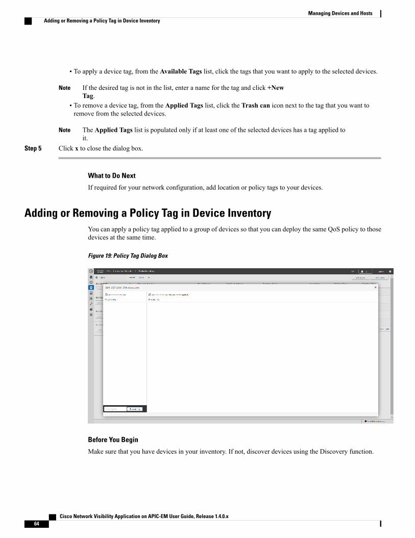
To apply a device tag, from the Available Tags list, click the tags that you want to apply to the selected devices.•
If the desired tag is not in the list, enter a name for the tag and click +NewTag.
Note
• To remove a device tag, from the Applied Tags list, click the Trash can icon next to the tag that you want toremove from the selected devices.
The Applied Tags list is populated only if at least one of the selected devices has a tag applied toit.
Note
Step 5 Click x to close the dialog box.
What to Do Next
If required for your network configuration, add location or policy tags to your devices.
Adding or Removing a Policy Tag in Device InventoryYou can apply a policy tag applied to a group of devices so that you can deploy the same QoS policy to thosedevices at the same time.
Figure 19: Policy Tag Dialog Box
Before You Begin
Make sure that you have devices in your inventory. If not, discover devices using the Discovery function.
Cisco Network Visibility Application on APIC-EM User Guide, Release 1.4.0.x64
Managing Devices and HostsAdding or Removing a Policy Tag in Device Inventory

SUMMARY STEPS
1. From the Navigation pane, click Device Inventory.2. From the Device Inventory toolbar, choose Layout > Tagging from the drop-down list.3. Select the check box to the left of the desired devices and click Set Policy Tag.4. Do one of the following:5. Click x to close the dialog box.
DETAILED STEPS
Step 1 From the Navigation pane, click Device Inventory.Step 2 From the Device Inventory toolbar, choose Layout > Tagging from the drop-down list.
The table refreshes and displays a Policy Tag column in addition to other columns.
Step 3 Select the check box to the left of the desired devices and click Set Policy Tag.For a single device, you can also clickAdd displayed in the Policy Tag column.Note
Step 4 Do one of the following:
• To apply a policy tag, from the Available Tags list, click the tag that you want to apply to the selected devices.
If the desired tag is not in the list, enter a name for the tag and click +NewTag.
Note
• To remove a policy tag, from the Applied Tags list, click the Trash can icon next to the tag that you want toremove from the selected devices.
The Applied Tags list is populated only if at least one of the selected devices has a tag applied toit.
Note
Step 5 Click x to close the dialog box.
What to Do Next
If you added a policy tag to devices and nowwant to configure QoS policies, see theCisco EasyQoS Applicationfor APIC-EM User Guide.
Adding or Removing Location TagsYou can apply a location tag to a device to name a device's geographic location. By applying the same tag toseveral devices, you can group them based on their common location. You can create a location tag and,optionally, place a corresponding location marker on a geographical map. For information, see Adding orChanging a Location Marker, on page 67.
Use the following guidelines when adding location tags:
• Location tag information is maintained on the controller only and not deployed to or dirived from thedevice itself.
• When location tags and markers are used, the Topology window displays them on a geographical map.
Cisco Network Visibility Application on APIC-EM User Guide, Release 1.4.0.x 65
Managing Devices and HostsAdding or Removing Location Tags

• A location defined on the controller is not the "civic-location" property that some devices support.
• Location tags cannot be attached to hosts.
• You can apply only one location tag to a device. However, you can use both a location tag and a devicetag together.
Figure 20: Set Location Tag Dialog Box
Before You Begin
You must have administrator (ROLE_ADMIN) permissions and access to all devices (RBAC Scope set toALL) to perform this procedure.
Step 1 From the Navigation pane, click Device Inventory.Step 2 From the Device Inventory toolbar, choose Layout > Tagging from the drop-down list.
The table refreshes and displays a Location column in addition to other columns.
Step 3 Select the check box to the left of the desired devices (or select the check box at the top of the list to select all devices)and click Set Location.
For a single device, you can also click theAdd link displayed in theLocation column for that device.Note
Step 4 Do one of the following:
• To apply a location tag, from the Available Tags list, click the tag that you want to apply to the selected devices.If the desired tag is not in the list, click the plus icon (+), enter a name for the tag, and click the check mark icon.
• To remove a location tag assignment from the devices, in the Edit Location field, click the x icon . The devicesnow have no location tag assignment.
• To change the current location tag to another one, click the new location tag that you want to assign.
Cisco Network Visibility Application on APIC-EM User Guide, Release 1.4.0.x66
Managing Devices and HostsAdding or Removing Location Tags

• To delete the location tag, first make sure that it is not in use (either change device assignments to other locationtags or remove the tag assignment altogether). Then, click the trash can icon next to the location tag that you wantto delete.
Step 5 When you are done, click x to close the dialog box.
What to Do Next
If required for your network configuration, add or remove other location tags to other devices or add locationmarkers.
Related Topics
Adding or Changing a Location Marker, on page 67
Adding or Changing a Location MarkerA location marker is an icon used to indicate the location of the devices associated with a location tag on ageographical map. You can add a location marker to devices in the Device Inventory window.
Before You Begin
You must have administrator (ROLE_ADMIN) permissions and access to all devices (RBAC Scope set toALL) to perform this procedure.
Make sure that you have devices in your inventory. If not, discover devices using the Discovery function.
You have already added location tags to your devices.
Step 1 From the Navigation pane, click Device Inventory.Step 2 From the Device Inventory toolbar, choose Layout > Tagging from the drop-down list.
The table refreshes and displays a Location column in addition to other columns.
Step 3 (Optional) To display devices with a specific location tag, from the Device Inventory toolbar, click Filters, enter alocation tag in the Device Location field, and click the + icon.
Step 4 Select the desired location tag from the Locations column.Because you are not assigning a location tag, it is not important which device you choose. When you add orremove a location marker, the change is applied to the location tag, and all devices that have the location tagwill be updated.
Note
Step 5 To add or change a locationmarker, select the location tag from theAvailable Locations pane and do one of the following:
• In the Address of Location field on the right side of the geographical map, enter the address where you want toplace the location marker. You can enter a complete address or part of an address, for example, a city name or zipcode. Cisco APIC-EM displays the location on the map. Click the map where you want the marker to be placedand confirm the action in the confirmation dialog box that appears.
• Position the map as close to the desired location as possible using your mouse to drag and drop, zoom in, and zoomout on the map, then click the map.
Cisco Network Visibility Application on APIC-EM User Guide, Release 1.4.0.x 67
Managing Devices and HostsAdding or Changing a Location Marker

If you need to reposition the marker, click the map again where you want the marker to beplaced.
Note
Figure 21: Edit Location Dialog Box Showing Location Marker
Step 6 (Optional) To add additional location markers, click another location tag and repeat Step 5.Step 7 When you are done, click x to close the dialog box.
Deleting a TagWhen a device tag, policy tag, or location tag is no longer needed, you can delete it, and it is removedpermanently from the controller. You can delete device tags using the Device Inventory window or theTopology window. Policy tags and location tags can be deleted only from the Device Inventory window.This procedure shows you how to delete tags from the Device Inventory window.
Before You Begin
You must have administrator (ROLE_ADMIN) permissions and access to all devices (RBAC Scope set toALL) to perform this procedure.
Make sure that you have devices in your inventory. If not, discover devices using the Discovery function.
Cisco Network Visibility Application on APIC-EM User Guide, Release 1.4.0.x68
Managing Devices and HostsDeleting a Tag

Before you can delete a tag, you need to remove it from all devices that have been assigned the tag.
Step 1 From the Navigation pane, click Device Inventory.Step 2 From the Device Inventory toolbar, choose Layout > Tagging from the drop-down list.Step 3 Do one of the following:
• To delete a device tag, click any number in the Device Tag column. From the Available Tags list, click the Trashcan icon next to the tag or tags that you want to delete.
• To delete a policy tag, click Add or the name of a policy tag in the Policy Tag column. From the Available Tagslist, click the Trash can icon next to the tag or tags that you want to delete.
• To delete a location tag, click Add or the name of a location tag in the Location column. From the AvailableLocations list, click the Trash can icon next to the tag or tags that you want to delete.
Step 4 Click OK to confirm the deletion.The tag is removed permanently from the controller.
If the deletion fails, the tag might still be assigned to devices. Remove the tag from these devices and try to delete thetag again.
Step 5 Click x to close the dialog box.
Cisco Network Visibility Application on APIC-EM User Guide, Release 1.4.0.x 69
Managing Devices and HostsDeleting a Tag

Updating Device CredentialsYou can update the discovery credentials of selected devices. The updated settings override the global andjob-specific settings for the selected devices.
Figure 22: Update Device Credentials Dialog Box
Before You Begin
Make sure that you have devices in your inventory. If not, discover devices using the Discovery function.
You must have either administrator (ROLE_ADMIN) or policy administrator (ROLE_POLICY_ADMIN)permissions and the appropriate RBAC scope to perform this procedure.
Step 1 From the Navigation pane, click Device Inventory.Step 2 Select the devices that you want to update.Step 3 Click Update Credentials.Step 4 Click OK to confirm this action.Step 5 From the Update Credentials dialog box, expand the SNMP area, if it is not already expanded.Step 6 In the Version field, choose the SNMP version from the drop-down list: V2C or V3 and complete the corresponding
fields:Both the SNMP and CLI credentials are updated together, so you need to provide both credentials. If you provideonly SNMP credentials, Cisco APIC-EM saves only the SNMP credentials. The CLI credentials are not updated.
Note
Cisco Network Visibility Application on APIC-EM User Guide, Release 1.4.0.x70
Managing Devices and HostsUpdating Device Credentials

Table 23: SNMP V2C Fields
DescriptionField
Read-Only community string value configured on devices that allowsthe controller to connect to and access the devices. This communitystring value must match the community string value that waspre-configured on the devices.
Read Community
Write community string value configured on devices that allows thecontroller to connect to, access, and change the devices. This communitystring value must match the community string value pre-configured onthe devices.
Write Community
Table 24: SNMP V3 Fields
DescriptionField
Authentication mode to be used. Valid modes are Authenticationand Privacy, Authentication, No Privacy, No Authentication, NoPrivacy.
Mode
Valid only if you chose Authentication and Privacy orAuthentication, No Privacy. Two authentication types are available:
• SHA—Authentication based on the Secure Hash algorithm(SHA). SHA is a hash algorithm that is used to authenticatepacket data.
•MD5—Authentication based on the Message Digest 5 (MD5)algorithm. MD5 is a hash algorithm that is used to authenticatepacket data.
Auth. Type
Valid only if you chose SHA orMD5.
Text string associated with the SNMP user and the chosenauthentication type (SHA or MD5).
Username
Valid only if you chose SHA orMD5.
Encrypted text string stored as the SNMP user password and associatedwith the authentication type (SHA or MD5).
Auth. Password
Cisco Network Visibility Application on APIC-EM User Guide, Release 1.4.0.x 71
Managing Devices and HostsUpdating Device Credentials

DescriptionField
Valid only if you chose Authentication and Privacy mode. Twoprivacy types are available:
• DES—Data Encryption Standard (DES) 56-bit encryption inaddition to authentication based on the Cipher Block Chaining(CBC) DES (DES-56) standard.
• AES128—Cipher Block Chaining (CBC) mode AES forencryption.
Privacy Type
SNMPv3 privacy password associated with the chosen privacy type(DES or AES128) and used to generate the secret key to encryptmessages that are exchanged with devices.
Privacy Password
Step 7 Expand the SNMP RETRIES AND TIMEOUT area, if it is not already expanded, and complete the following fields:
Table 25: SNMP Retries and Timeout Fields
DescriptionField
Number of attempts the controller makes to communicatewith the devices using SNMP. The default is 3 tries.
Retries
Number of seconds the controller waits while attemptingto communicate with the devices using SNMP before theattempt fails. The default is 5 seconds.
Timeout
Step 8 Expand the CLI area, if it is not already expanded, and complete the following fields:Both the SNMP and CLI credentials are updated together, so you need to provide both credentials. If you provideonly SNMP credentials, Cisco APIC-EM saves only the SNMP credentials. The CLI credentials are not updated.
Note
Table 26: CLI Fields
DescriptionField
Protocol used from a remotemanagement station to connectdevice CLI. Valid options are Telnet (Telnet TCP/IP) orSSH2 (Secure Shell 2.0).
Protocol
Identification used to log into a device's CLI.Username
Password used to log into a device's CLI.Password
After successful login to the CLI, password used to accessPrivileged EXEC mode.
Enable Password
Cisco Network Visibility Application on APIC-EM User Guide, Release 1.4.0.x72
Managing Devices and HostsUpdating Device Credentials

Step 9 Click Update.
Resynchronizing Device InformationYou can select devices to be polled immediately for updated device and status information, regardless of thepolling interval that is set. A maximum of 40 devices can be resynchronized at the same time.
Figure 23: Device Inventory Window Showing Resync in Progress
Step 1 From the Navigation pane, click Device Inventory.Step 2 Select the device or devices on which you want to gather information about.Step 3 Click Resync.Step 4 Confirm the resynchronization by clicking OK.
Cisco Network Visibility Application on APIC-EM User Guide, Release 1.4.0.x 73
Managing Devices and HostsResynchronizing Device Information

Running Commands on DevicesYou can run show commands and other read-only commands on selected devices and display the output inCisco APIC-EM. To determine the allowed command keywords, from the global toolbar, clickAPI >NetworkPoller > network-device-poller > /network-device-poller/cli/legit-reads > Try it out!
From the GUI, you can run a maximum of 5 commands per device, with a maximum of 20 devices per request.When a device is part of another request that has not completed yet, no other commands are executed on it.
Access points are not supported. If you choose access points, they are omitted from executing commands.Commands are only run on the other selected devices.
Before You Begin
The command runner application is not installed on Cisco APIC-EM by default. To use the command runningapplication, you need to download the image from Cisco.com, install it, and enable the Command Runnerapplication. For information, see the Cisco Application Policy Infrastructure Controller Enterprise ModuleAdministrator Guide.
You must have either administrator (ROLE_ADMIN) or policy administrator (ROLE_POLICY_ADMIN)permissions and the appropriate RBAC scope to perform this procedure.
Make sure that you have devices in your inventory. If not, discover devices using the Discovery function.
Step 1 From the Navigation pane, click Device Inventory.Step 2 Select the device on which you want to run commands.Step 3 Click Command Runner.Step 4 In the Command field, enter the command that you want to run and click the plus sign (+) icon to add the command to
the list of commands to be run.You can add only one command at a time and up to 5 commands total.
Step 5 When you have defined all of the commands that you want to run, click Run.Cisco APIC-EM runs the commands on the selected devices and displays the command output.
Command Runner does not maintain any cache or history of the command results. If you run commands andthen close or navigate to a different window, all actions performed in command runner and their results are lost.
Note
Updating a Device's Polling IntervalYou can update the polling interval at the global level for all devices on the Settings > Polling Interval pageor at the device level for a specific device in theDevice Inventorywindow. When you set the polling intervalat the device level, that value takes precedence over the global polling interval value.
Cisco Network Visibility Application on APIC-EM User Guide, Release 1.4.0.x74
Managing Devices and HostsRunning Commands on Devices

For information about setting the polling interval at the global level, see the Cisco Application PolicyInfrastructure Controller Enterprise Module Administrator Guide.
Figure 24: Update Polling Interval Dialog Box
Before You Begin
Make sure that you have devices in your inventory. If not, discover devices using the Discovery function.
You must have either administrator (ROLE_ADMIN) or policy administrator (ROLE_POLICY_ADMIN)permissions and the appropriate RBAC scope to perform this procedure.
Step 1 From the Navigation pane, click Device Inventory.Step 2 Select the devices that you want to update.Step 3 Click Update Polling Interval.Step 4 Click OK to confirm this action.Step 5 From the Update Polling Interval dialog box, in the Status field, click Enabled to turn on polling or click Disabled to
turn off polling.Step 6 In the Polling Time field, enter the time interval (in minutes) between successive polling cycles. Valid values are from
25 to 1440 minutes (24-hours).The device-specific polling time supersedes the global polling time. If you set the device-specific polling timeand then change the global polling time, Cisco APIC-EM continues to use the device-specific polling time.
Note
Step 7 Click Update.
Cisco Network Visibility Application on APIC-EM User Guide, Release 1.4.0.x 75
Managing Devices and HostsUpdating a Device's Polling Interval

Managing Your Host InventoryCisco APIC-EM displays information about the discovered hosts in the Host Inventory window.
The following table describes the information that is displayed about the hosts in your inventory.
Use the filters located below the Host Inventory table to limit the number of hosts displayed in the table(10, 25, 50, 100) or to view groups of hosts at a time (First, Previous, Next, Last, or 1-3).
Note
Figure 25: Host Inventory Window
The following table describes the information that is displayed about the hosts in your inventory.
Table 27: Host Inventory
DescriptionHost Inventory
Name of the host.Host Name
MAC address of the host.Host MAC address
IP address of the host.Host IP address
Type of host (wired or wireless).Host type
IP address of the device that is connected to the host.
IP addresses of only wired devices areshown.
Note
Connected Network Device IP Address
Cisco Network Visibility Application on APIC-EM User Guide, Release 1.4.0.x76
Managing Devices and HostsManaging Your Host Inventory

DescriptionHost Inventory
Name of the interface that the device is connected to.For example, GigabitEthernet1/0/24.
Connected Interface Name
Filtering Hosts in the Host Inventory WindowYou can filter the hosts displayed in theHost Inventory window by host MAC address, host IP address, hostname, host type, connected network device IP address, or connected interface name.
Figure 26: Host Inventory Window Showing Filters Pane
Before You Begin
Make sure that you have hosts in your inventory. If not, discover them using the Discovery function.
Step 1 From the Host Inventory toolbar, click Filters.You can choose from the following filter options:
• Host MAC Address
• Host IP Address
• Host Name
• Host Type
• Connected Network Device IP Address
• Connected Interface Name
Cisco Network Visibility Application on APIC-EM User Guide, Release 1.4.0.x 77
Managing Devices and HostsFiltering Hosts in the Host Inventory Window

Step 2 Enter the appropriate value in the selected filter field.For example, for the Host Name filter, enter the name of the host.
The controller presents you with auto-complete values as you enter values in the other fields. Choose one of the suggestedvalues or finish entering the value.
You can also use a wildcard (asterisk) with these filters. You can enter values with the asterisk at the beginning,end, or in the middle of the string value.
Note
Step 3 Click the plus (+) icon to perform the filter.The data displayed in the Devices table automatically updates according to your filter selection.
Step 4 (Optional) If needed, add more filters following the above steps.You can filter on more than one value per filter or across several different filtertypes.
Note
Step 5 To remove the filter, click the x icon next to the filter value.
Cisco Network Visibility Application on APIC-EM User Guide, Release 1.4.0.x78
Managing Devices and HostsFiltering Hosts in the Host Inventory Window

C H A P T E R 6Using the Topology Map
• About Topology, page 79
• Displaying Device Data, page 85
• Aggregating Devices, page 86
• Configuring the Topology Structure, page 90
• Saving a Topology Layout, page 92
• Opening a Saved Topology Layout, page 93
• Changing a Device's Role From the Topology Window, page 94
• Searching for Devices and Hosts, page 96
• Adding or Removing a Device Tag in Topology , page 97
• Adding or Removing a Policy Tag in Topology, page 99
• Displaying Devices with Tags, page 100
About TopologyThe Topology window displays a graphical view of your network. Using the discovery settings that you haveconfigured, the Cisco APIC-EM discovers and maps devices to a physical topology with detailed device-leveldata.
The entire network topology is displayed. However, you will only have access to device information andfunctions if the device is listed in the device scope in your user profile. If the device is not in your devicescope, then you will not be able to view additional information about the device, or, in the case of a userprofile with ROLE_ADMIN or ROLE_POLICY_ADMIN, tag devices or change device roles.
Note
Cisco Network Visibility Application on APIC-EM User Guide, Release 1.4.0.x 79

To access the Topology window, from the Navigation pane, click Topology. The Topology window appearsand displays a topology map of your network.
Figure 27: Topology Window
The topology map includes the following key features:
• Auto-visualization of Layer 2 and 3 topologies on top of the physical topology for a granular view fordesign planning and simplified troubleshooting.
• For a Layer 2 topology, display of configured VLANs within your network. For a Layer 3 topology,display of OSPF, IS-IS, and so on, depending on what is currently configured and in use in your network.
• Device information.
• Display of a path trace in the topology map. For additional information about performing a path trace,see the Cisco Path Trace Application for APIC-EM User Guide.
Individual device configurations are retrieved and stored in a network information database (NIDB).Note
Cisco Network Visibility Application on APIC-EM User Guide, Release 1.4.0.x80
Using the Topology MapAbout Topology

Topology ToolbarThe Topology toolbar is located at the top of the Topology window.
Figure 28: Topology Window
DescriptionNameIcon
Enables or disables device aggregation. Aggregatingdevices means grouping devices together. You cangroup devices in any way that makes sense to you.
You can save the layout for future reference byclicking the Save icon.
This grouping does not effect the physicalconfiguration on the devices. Aggregation isenabled by default.
Toggle Aggregation
Allows you to select multiple devices by draggingthe mouse over the desired devices or shift-clickingon devices. You can also select multiple groups ofdevices by clicking shift and dragging the mouseover a group of devices. After selecting the groupof devices, you can aggregate or tag them. If youaggregate devices of different product families, theCisco APIC-EM shows them as generic devices(without a device type) and the number of devices.Multiselect is off by default.
Toggle Multiselect
Cisco Network Visibility Application on APIC-EM User Guide, Release 1.4.0.x 81
Using the Topology MapTopology Toolbar

DescriptionNameIcon
Searches for a host or device by host name, devicename, device type, or IP address. As you enterinformation into this field, the Cisco APIC-EMdisplays matches. Select the host or device fromthe results that appear. The selected host or deviceappears in the Topology window.
Search Topology
Allows you to choose a filter that you can apply tothe topology map. For each filter, you can makeadditional adjustments using theAdvanced options.For information, see Configuring the TopologyStructure, on page 90.
• Enterprise (Default)—Displays your networktopology, separating your devices onconnection branches. For example, if a groupof devices are connected to Router A, andanother group of devices are connected toRouter B, the topology would show thisdivision and would separate the devices.
• Connections—Displays the devices accordingto their number of connections. Starting fromthe left, the devices with no connections aredisplayed, then devices with one connection,then devices with two connections, and so on.
• Type and Role—Displays the devicesaccording to their role in the network: accessrouter, distribution switch, core switch andhub, and boarder router.
• Advanced—Provides options for you torefine the topology display.
Filters
Adjusts the Topology window's view.Click the - (minus) icon to minimize theview of the network hosts and devices.
NoteZoom out
Adjusts the Topology window's view. Click the +(plus) icon on the menu bar to maximize the viewof the network hosts and devices.
Zoom in
Toggles between displaying the device icons indifferent colors or in a single color. Color codingis enabled by default.
Toggle Color Code
Cisco Network Visibility Application on APIC-EM User Guide, Release 1.4.0.x82
Using the Topology MapTopology Toolbar

DescriptionNameIcon
Displays the available device tags. Clicking on anindividual tag highlights the device or devices inthe Topology window that have this tag.
You can also apply tags to devices by selecting thedevice, clicking Device Tagging in the DeviceInformation dialog box, and then creating andapplying the tags.
Device Tags
Displays the available policy tags. Clicking on anindividual tag adds the device to the policy scope.
You can also applypolicy tags to devices in theEasyQoS > Policy Scopes.
Policy Tags
Displays devices with the following attributes onthe topology map:
• Layer 2—Displays devices based on theselected VLAN or Layer 2 protocol. Selecteither a VLAN from the drop-down menu orone of the Layer 2 protocols.
You can also access a managementnetwork view by choosing amanagement selection from thedrop-down menu.
Note
• Layer 3—Displays devices based on theselected Layer 3 protocol. The followingLayer 3 protocols are available:
◦Intermediate System-to-IntermediateSystem (IS-IS)
◦Open Shortest Path First (OSPF)
◦Enhanced Interior Gateway RoutingProtocol (EIGRP)
◦Static-Route
The default Layer 3 topology has allLayer 3 protocols.
Note
• VRF—Displays devices that have VirtualRouting and Forwarding (VRF) tables.
Layers
Cisco Network Visibility Application on APIC-EM User Guide, Release 1.4.0.x 83
Using the Topology MapTopology Toolbar

DescriptionNameIcon
Displays the following options:
• Save Current Layout—Saves the currentlayout, device aggregations, and labels.
• Load Saved Layout—Loads the previouslysaved layout, device aggregations, and labels)options.
Save and Load Options
Displays the Topology map view. Click this iconto view the network topology in a graphicalrepresentation of your network's physical location.
This icon is displayed only if you haveadded location markers for your devicesfrom the Device Inventory window.
Note
Map view
Topology IconsThe following icons appear in the Topology window:
DescriptionNetwork ElementIcon
Representation of the external network.Cloud
Displays the device name.Router
Displays the device name.Switch
Displays the device name.Access Point
Displays the device name.Wireless LANController
Cisco Network Visibility Application on APIC-EM User Guide, Release 1.4.0.x84
Using the Topology MapTopology Icons

DescriptionNetwork ElementIcon
Displays the number of aggregated devices and thedevice type.
If different devices types are aggregated, onlythe number of aggregated devices is displayed.
Note
Aggregated Devices
Displays the device name. The device icon is displayedwith a location marker as a background.
If you add location markers to your devices (from theDevice Inventorywindow) and then click Topology inthe navigation pane or click theMap button on theTopology toolbar, the Topology map view appears. Themap view shows where you have placed your locationmarkers (for example, San Jose and London). Click alocation marker on the map to display the topology forthat location (for example, San Jose).
Devices that use a different location marker (forexample, London) are shown with a location marker asa background.
Location Marker
Lines between devices.
Click on a link to display information about theconnected devices.
Some of the links may be hidden due to deviceaggregations.
Note
Links
Displaying Device DataYou can display data for a specific device in the Topology window. Displaying device data is helpful whentroubleshooting network connectivity issues between devices.
The device data that is accessible in the Topology window is also accessible in the Device Inventorywindow.
Note
The following device data is available:
• Location (Location information is displayed if the selected device icon has a locationmarker background.Click the Location link to display the topology for devices that share that location marker.)
• Type
• Device role (For information about changing the device role, see Changing the Device Role, on page61.
• IP address
Cisco Network Visibility Application on APIC-EM User Guide, Release 1.4.0.x 85
Using the Topology MapDisplaying Device Data
• MAC address
• OS (operating system)
• Software version
• Ports
• Gigabit Ethernet ports
• 10-Gigabit Ethernet ports
• Management ports
• VLAN (if exists)
• Number of connections
• List of connected devices (Each connected device shows its device type (icon) and the number ofconnections. Clicking on a connected device displays the details for that device.)
• Tags
Step 1 From the Navigation pane, click Topology.The Topology window appears.
If you have added location markers for your devices from the Device Inventory window, the Topology mapview appears. Click a location marker to display the Topology for that location.
Note
Step 2 To display data for a specific device, click that device in the Topology window.Step 3 To display a list of aggregated devices, do the following:
a) In the Topology window, click an aggregated devices icon.b) In the Device Details pane, click the Details link for each device to view the device data.c) Click the Aggregated Results link to return to the list of aggregated devices.
What to Do Next
Select and review data from other devices within your network, or perform other tasks including the following:
• Aggregate or disaggregate selected groups
• Search for device using device names and IP addresses
• Apply tags to devices within your network
• Change the device role
Aggregating DevicesYou use the Cisco APIC-EM device aggregation feature to adjust how devices are displayed in the Topologywindow. This feature enhances network navigation and manageability.
Cisco Network Visibility Application on APIC-EM User Guide, Release 1.4.0.x86
Using the Topology MapAggregating Devices

Aggregating Devices in the Topology WindowYou can aggregate and disaggreate devices into and out of groups in the Topology window.
Before You Begin
Scan your network using the discovery functionality of the Cisco APIC-EM to populate device and hostinventory for the database.
Determine how the devices within your network configuration are to be visually grouped and organized.
Step 1 Click Topology in the navigation pane.The Topology window appears.
If you have added location markers for your devices from the Device Inventory window, the Topology mapview appears. Click a location marker to display the Topology for that location.
Note
Step 2 Click the Toggle Aggregation icon to enable device aggregation.Device aggregation is enabled bydefault.
Note
Step 3 Drag and drop a device icon onto another device icon.The device icon changes to an aggregated devices icon. For more information about the aggregated devices icon, seeTopology Icons, on page 84.
Cisco Network Visibility Application on APIC-EM User Guide, Release 1.4.0.x 87
Using the Topology MapAggregating Devices in the Topology Window

You can also select multiple devices by clicking theMultiselect icon, dragging the mouse over the desireddevices, and clicking the Aggregate Selected link.
Note
Disaggregating Devices in the Topology WindowYou can ungroup devices by disaggregating them in the Topology window.
Figure 29: Topology Window Showing Disaggregate Option in Devices List
Before You Begin
Scan your network using the discovery functionality of the Cisco APIC-EM to populate device inventory forthe database.
Determine how the devices within your network configuration are to be visually grouped and organized.
Step 1 From the Navigation pane, click Topology.The Topology window appears.
If you have added location markers for your devices from the Device Inventory window, the Topology mapview appears. Click a location marker to display the Topology for that location.
Note
Cisco Network Visibility Application on APIC-EM User Guide, Release 1.4.0.x88
Using the Topology MapDisaggregating Devices in the Topology Window

Step 2 Click on an aggregated devices icon.A list of the aggregated devices appears.
Step 3 From the list, click the Disaggregate link for each device that you want to remove from the aggregated devices.The device is removed from the list and from the aggregated devices icon. The aggregated device label and the aggregateddevices icon are updated to reflect the number of devices.
Changing the Aggregated Devices LabelThe default label for aggregated devices is the number of devices and the device type (# devicetypeDevices).However, you can change the default label to one that is meaningful in the context of your network topology.
Before You Begin
Scan your network using the discovery functionality of the Cisco APIC-EM to populate device inventory forthe database.
Determine how the devices within your network configuration are to be visually grouped and organized.
Step 1 From the Navigation pane, click Topology.The Topology window appears.
If you have added location markers for your devices from the Device Inventory window, the Topology mapview appears. Click a location marker to display the Topology for that location.
Note
Step 2 Click an aggregated devices icon.
Cisco Network Visibility Application on APIC-EM User Guide, Release 1.4.0.x 89
Using the Topology MapChanging the Aggregated Devices Label

A list of the aggregated devices appears. At the top of the list is the aggregated devices label.
Step 3 Click the aggregated devices label to open an edit field where you can change the label.Step 4 Change the label, then click outside of the edit field to save your changes.
Configuring the Topology StructureYou can choose from three default topology layouts. You can also use advanced settings to modify theselayouts, such as the overall size of the topology graph, the spacing that separates individual elements, andmore.
Figure 30: Topology Window Showing Filters Drop-Down List
Before You Begin
Scan your network using the discovery functionality of the Cisco APIC-EM to populate device inventory forthe database.
Step 1 From the Navigation pane, click Topology.The Topology window appears.
If you have added location markers for your devices from the Device Inventory window, the Topology mapview appears. Click a location marker to display the Topology for that location.
Note
Cisco Network Visibility Application on APIC-EM User Guide, Release 1.4.0.x90
Using the Topology MapConfiguring the Topology Structure

Step 2 From the Topology toolbar, click the Filters icon.Step 3 Select a filter from the drop down list. Available options are Enterprise Collapsed, Enterprise Expanded, or Device
Type & Role.Step 4 Click the Advanced View button to configure how each filter is displayed. Click the Basic View button to return to the
basic view.Advanced ViewBasic ViewFilter
Device type—Use the slider to adjust the amount ofspace between device icons based on their device types.
cloud-centralizeX—When checked (default), thedevice icons are centered along the X axis. Whenunchecked, the device icons are aligned to the X axis.
Device role—Use the slider to adjust the amount ofspace between device icons based on their device roles.
Branch— Use the slider to adjust the amount of spacebetween branches.
Node overlap—Use the slider to adjust the amount ofspace between nodes.
Select x or y from the drop down next to eachslider to change how the device icons aredisplayed, horizontally or vertically.
Note
Arranges the device icons into astructured connection hierarchical view,from top to bottom.
Enterprise
Connections—Use the slider to adjust the amount ofspace between connections.
Node overlap—Use the slider to adjust the amount ofspace between nodes.
centralizeY—When checked, the device icons arecentered along the Y axis.When unchecked, the deviceicons are aligned to the Y axis.
Select x or y from the drop down next to eachslider to change how the device icons aredisplayed, horizontally or vertically.
Note
Arranges the device icons from left toright based on the number of connections,from least to most.
Aggregated devices aredisaggregated in this view.
Note
Connections
Device type—Use the slider to adjust the amount ofspace between device icons based on their device types.
Device role—Use the slider to adjust the amount ofspace between device icons based on their device roles.
Node overlap—Use the slider to adjust the amount ofspace between nodes.
centralizeX—When checked, the device icons arecentered along the X axis.When unchecked, the deviceicons are aligned to the X axis.
Select x or y from the drop down next to eachslider to change how the device icons aredisplayed, horizontally or vertically.
Note
Arranges the device icons from top tobottom based on device type (cloud,router, WLC, switch, access point, wired,wireless) and role (border router, core,distribution, and access)
Aggregated devices aredisaggregated in this view.
Note
Type and Role
Cisco Network Visibility Application on APIC-EM User Guide, Release 1.4.0.x 91
Using the Topology MapConfiguring the Topology Structure

What to Do Next
Save the current layout or load a previously saved layout. For information, see Saving a Topology Layout,on page 92 and Opening a Saved Topology Layout, on page 93.
Saving a Topology LayoutYou can save a topology layout so that you can open and view it later.
Figure 31: Topology Window Showing Save Dialog Box
Before You Begin
You must have administrator role permissions.
You must have administrator (ROLE_ADMIN) permissions and access to all devices (RBAC Scope set toALL) to perform this procedure.
Make sure that you have devices in your inventory. If not, discover devices using the Discovery function.
Step 1 From the Navigation pane, click Topology.The Topology window appears.
Cisco Network Visibility Application on APIC-EM User Guide, Release 1.4.0.x92
Using the Topology MapSaving a Topology Layout

Step 2 From the Topology toolbar, click the Save icon.Step 3 In the Topology Title field, enter a name for the topology and click Save as New.Step 4 Click OK to confirm the save.
The topology is saved and the name appears at the top of the dialog box.
Opening a Saved Topology LayoutYou can open a topology layout that you have previously saved.
Figure 32: Topology Window Showing Previously Saved Topology Layouts in Save Dialog Box
Before You Begin
You must have administrator (ROLE_ADMIN) permissions and access to all devices (RBAC Scope set toALL) to perform this procedure.
Make sure that you have devices in your inventory. If not, discover devices using the Discovery function.
Step 1 From the Navigation pane, click Topology.The Topology window appears.
Step 2 From the Topology toolbar, click the Save icon.A dialog box appears listing the saved topology layouts.
Cisco Network Visibility Application on APIC-EM User Guide, Release 1.4.0.x 93
Using the Topology MapOpening a Saved Topology Layout
Step 3 For the topology layout that you want to open, click the Folder icon..Step 4 Click OK to confirm.
The topology layout opens in the Topology window.
Changing a Device's Role From the Topology WindowDuring the scan process, a device role is automatically assigned to each discovered device. The device roleis used for identifying and grouping devices according to their responsibilities and placement within thenetwork.
A device can have one of the following roles within the Cisco APIC-EM:
• Unknown—Device role is unknown.
• Access—Device is located within and performs tasks required for the access layer or first tier/edge.
• Border Router—Device performs the tasks required for a border router.
• Distribution—Device is located within and performs tasks required for the distribution layer.
• Core—Device is located within and performs tasks required for the core.
You can change the device role when you select a device and display the device data.
Cisco Network Visibility Application on APIC-EM User Guide, Release 1.4.0.x94
Using the Topology MapChanging a Device's Role From the Topology Window

You can also change the device role from the Device Inventory window.Note
Figure 33: Topology Window Showing Role Drop-Down List
Before You Begin
Scan your network using the discovery functionality of the Cisco APIC-EM to populate device inventory forthe database.
Step 1 From the Navigation pane, click Topology.The Topology window appears.
If you have added location markers for your devices from the Device Inventory window, the Topology mapview appears. Click a location marker on the map to display the Topology for that location.
Note
Step 2 Click a specific device in the Topology window to select it.Step 3 Choose a role from the Role drop-down list: Access, Core, Distribution, or Border Router.Step 4 (Optional) Select additional devices and change device roles.Step 5 Click the Filters icon on the Topology toolbar.Step 6 (Optional) Select a filter from the drop down list. Available options are Branch, Connections, or Device and Role.Step 7 Click the refresh button to the right of the filter type to update all of the device roles.
The Topology structure refreshes showing the changed device roles.
Cisco Network Visibility Application on APIC-EM User Guide, Release 1.4.0.x 95
Using the Topology MapChanging a Device's Role From the Topology Window
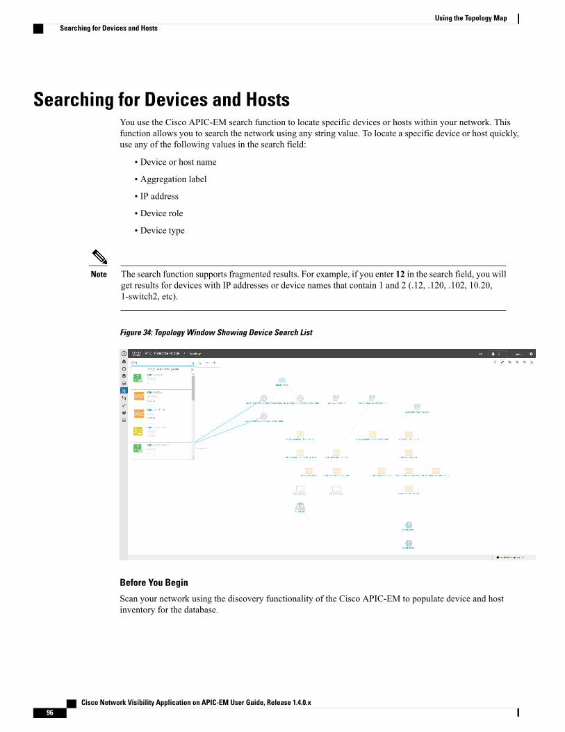
Searching for Devices and HostsYou use the Cisco APIC-EM search function to locate specific devices or hosts within your network. Thisfunction allows you to search the network using any string value. To locate a specific device or host quickly,use any of the following values in the search field:
• Device or host name
• Aggregation label
• IP address
• Device role
• Device type
The search function supports fragmented results. For example, if you enter 12 in the search field, you willget results for devices with IP addresses or device names that contain 1 and 2 (.12, .120, .102, 10.20,1-switch2, etc).
Note
Figure 34: Topology Window Showing Device Search List
Before You Begin
Scan your network using the discovery functionality of the Cisco APIC-EM to populate device and hostinventory for the database.
Cisco Network Visibility Application on APIC-EM User Guide, Release 1.4.0.x96
Using the Topology MapSearching for Devices and Hosts

Determine the string value to be used within your network for your search.
Step 1 Click Topology in the navigation pane.The Topology window appears.
If you have added location markers for your devices from the Device Inventory window, the Topology mapview appears. Click a location marker on the map to display the Topology for that location.
Note
Step 2 From the Topology toolbar, enter a keyword in the Search Topology field.As you begin typing, the controller displays a list of possible matches to your entry.
You can click the x in the search field to clear the search keyword field and the results.Note
Step 3 Click on a device from the search results to highlight that device and its links in the Topology window. Click on thedevice again to display detailed data for that device.
Step 4 Proceed with any provisioning or troubleshooting tasks on the located devices or hosts.
What to Do Next
Search using other string values for other devices or hosts within your network, or perform other tasks includingthe following:
• Viewing the data for specific devices
• Applying tags to devices within your network
• Host a meeting using the topology co-editor to collaborate with other users in real-time on the network
Adding or Removing a Device Tag in TopologyIn the Topology window, you can add device tags to associate devices that share a common attribute. Forexample, you can create a tag and use it to group devices based upon a platform ID, Cisco IOS releases, orlocation. Similarly, you can remove tags from devices.
You can also add or remove device tags from the Device Inventory window or from the EasyQoS window.For information, see Adding or Removing a Device Tag in Device Inventory, on page 63 or theCisco EasyQoSApplication for APIC-EM User Guide.
Cisco Network Visibility Application on APIC-EM User Guide, Release 1.4.0.x 97
Using the Topology MapAdding or Removing a Device Tag in Topology

Applying a tag to a host is not supported.Note
Figure 35: Device Tag Dialog Box
Before You Begin
• Make sure that you have devices in your inventory. If not, discover devices using the Discovery function.
Step 1 From the Navigation pane, click Topology.Step 2 Click the device or devices you want to tag. To select more than one device, click theMultiselect icon. For information
about how to use the multiselect function, see Topology Icons, on page 84.To deselect devices in your selection, click outside of the selected device.Note
The Device Information dialog box appears.Step 3 Click Device Tagging.
The Device Tagging dialog box appears.
Step 4 From the Available Tags column, click a tag to apply it to the selected device or devices. If the tag you want does notexist, you can create it by entering the name of the tag in the Device Tag Title field and clicking +Create Tag.
Step 5 When you are done, click x to close the dialog box.
Cisco Network Visibility Application on APIC-EM User Guide, Release 1.4.0.x98
Using the Topology MapAdding or Removing a Device Tag in Topology

Adding or Removing a Policy Tag in TopologyBefore you can create a QoS policy, you need to identify the policy scope, that is, the devices that will beconfigured with QoS policies. You identify the devices by tagging them with a policy tag.
You can also add or remove policy tags from the Device Inventory window or the EasyQoS window. Forinformation, see Adding or Removing a Device Tag in Device Inventory, on page 63 or the Cisco EasyQoSApplication for APIC-EM User Guide.
Figure 36: Policy Tag Dialog Box
Before You Begin
• Make sure that you have devices in your inventory. If not, discover devices using the Discovery function.
From the Topology or Device Inventory window, verify that the device roles assigned to devices duringdiscovery are appropriate for your network design. If necessary, change any of the device roles that are notappropriate.
Step 1 From the Navigation pane, click Topology.Step 2 Click the device or devices you want to tag. To select more than one device, click theMultiselect icon. For information
about how to use the multiselect function, see Topology Icons, on page 84.To deselect devices in your selection, click outside of the selected device.Note
The Device Information dialog box appears.Step 3 Click Policy Tagging.
TheMultiple Policy Tagging dialog box appears.
Cisco Network Visibility Application on APIC-EM User Guide, Release 1.4.0.x 99
Using the Topology MapAdding or Removing a Policy Tag in Topology

Step 4 From the Available Policy Tags column, click a tag to apply it to the selected device or devices. If the tag you wantdoes not exist, you can create it by entering the name of the tag in the Policy Tag Title field and clicking +Create Tag.
Step 5 When you are done, click x to close the dialog box.
Displaying Devices with TagsTo display tagged devices from the Topology window, perform the following steps.
Figure 37: Topology Window Showing Devices with Tags
Before You Begin
You should have performed the following tasks:
• Discovered the devices on your network to populate the device inventory database.
• Created tags and applied them either through the Device Inventory or Topology window.
Step 1 From the Navigation pane, click Topology.The Topology window appears.
Step 2 From the Topology toolbar, click the Tags.A tag selection box appears.
Cisco Network Visibility Application on APIC-EM User Guide, Release 1.4.0.x100
Using the Topology MapDisplaying Devices with Tags

Step 3 To identify the devices associated with a tag, click the tag. To return the devices to their normal display, click the tagagain.Tags are color-coded, so when you click a tag, a circle of the same color is drawn around its associated devices.
You can click more than one tag at a time. The tag that you chose to display first is the innermost circle aroundthe device, followed by the next tag as the next circle, and so on.
Note
Cisco Network Visibility Application on APIC-EM User Guide, Release 1.4.0.x 101
Using the Topology MapDisplaying Devices with Tags

Cisco Network Visibility Application on APIC-EM User Guide, Release 1.4.0.x102
Using the Topology MapDisplaying Devices with Tags


![Integración avanzada de Cisco ACI...Cisco ACI Kit [Leaf & Spine Fabric + APIC] APIC vSphere LAN Logicalis Spine: Nexus C9336PQ Leaf: Nexus C9372PX Extensión 13 OSPF 10 Area (NSSA)](https://img.dokumen.tips/doc/110x75/613b9313f8f21c0c826912af/integracin-avanzada-de-cisco-aci-cisco-aci-kit-leaf-spine-fabric-.jpg)