Embed Size (px)
Citation preview

Cisco IOS Mobile Wireless Command ReferenceRelease 12.3T
Corporate HeadquartersCisco Systems, Inc.170 West Tasman DriveSan Jose, CA 95134-1706 USAhttp://www.cisco.comTel: 408 526-4000
800 553-NETS (6387)Fax: 408 526-4100
Text Part Number: OL-4426-02

THE SPECIFICATIONS AND INFORMATION REGARDING THE PRODUCTS IN THIS MANUAL ARE SUBJECT TO CHANGE WITHOUT NOTICE. ALL STATEMENTS, INFORMATION, AND RECOMMENDATIONS IN THIS MANUAL ARE BELIEVED TO BE ACCURATE BUT ARE PRESENTED WITHOUT WARRANTY OF ANY KIND, EXPRESS OR IMPLIED. USERS MUST TAKE FULL RESPONSIBILITY FOR THEIR APPLICATION OF ANY PRODUCTS.
THE SOFTWARE LICENSE AND LIMITED WARRANTY FOR THE ACCOMPANYING PRODUCT ARE SET FORTH IN THE INFORMATION PACKET THAT SHIPPED WITH THE PRODUCT AND ARE INCORPORATED HEREIN BY THIS REFERENCE. IF YOU ARE UNABLE TO LOCATE THE SOFTWARE LICENSE OR LIMITED WARRANTY, CONTACT YOUR CISCO REPRESENTATIVE FOR A COPY.
The Cisco implementation of TCP header compression is an adaptation of a program developed by the University of California, Berkeley (UCB) as part of UCB’s public domain version of the UNIX operating system. All rights reserved. Copyright © 1981, Regents of the University of California.
NOTWITHSTANDING ANY OTHER WARRANTY HEREIN, ALL DOCUMENT FILES AND SOFTWARE OF THESE SUPPLIERS ARE PROVIDED “AS IS” WITH ALL FAULTS. CISCO AND THE ABOVE-NAMED SUPPLIERS DISCLAIM ALL WARRANTIES, EXPRESSED OR IMPLIED, INCLUDING, WITHOUT LIMITATION, THOSE OF MERCHANTABILITY, FITNESS FOR A PARTICULAR PURPOSE AND NONINFRINGEMENT OR ARISING FROM A COURSE OF DEALING, USAGE, OR TRADE PRACTICE.
IN NO EVENT SHALL CISCO OR ITS SUPPLIERS BE LIABLE FOR ANY INDIRECT, SPECIAL, CONSEQUENTIAL, OR INCIDENTAL DAMAGES, INCLUDING, WITHOUT LIMITATION, LOST PROFITS OR LOSS OR DAMAGE TO DATA ARISING OUT OF THE USE OR INABILITY TO USE THIS MANUAL, EVEN IF CISCO OR ITS SUPPLIERS HAVE BEEN ADVISED OF THE POSSIBILITY OF SUCH DAMAGES.
CCSP, CCVP, the Cisco Square Bridge logo, Follow Me Browsing, and StackWise are trademarks of Cisco Systems, Inc.; Changing the Way We Work, Live, Play, and Learn, and iQuick Study are service marks of Cisco Systems, Inc.; and Access Registrar, Aironet, ASIST, BPX, Catalyst, CCDA, CCDP, CCIE, CCIP, CCNA, CCNP, Cisco, the Cisco Certified Internetwork Expert logo, Cisco IOS, Cisco Press, Cisco Systems, Cisco Systems Capital, the Cisco Systems logo, Cisco Unity, Empowering the Internet Generation, Enterprise/Solver, EtherChannel, EtherFast, EtherSwitch, Fast Step, FormShare, GigaDrive, GigaStack, HomeLink, Internet Quotient, IOS, IP/TV, iQ Expertise, the iQ logo, iQ Net Readiness Scorecard, LightStream, Linksys, MeetingPlace, MGX, the Networkers logo, Networking Academy, Network Registrar, Packet, PIX, Post-Routing, Pre-Routing, ProConnect, RateMUX, ScriptShare, SlideCast, SMARTnet, StrataView Plus, TeleRouter, The Fastest Way to Increase Your Internet Quotient, and TransPath are registered trademarks of Cisco Systems, Inc. and/or its affiliates in the United States and certain other countries.
All other trademarks mentioned in this document or Website are the property of their respective owners. The use of the word partner does not imply a partnership relationship between Cisco and any other company. (0502R)
Mobile Wireless Command Reference, Release 12.3 TCopyright © 2005, Cisco Systems, Inc. All rights reserved.

C O N T E N T S
Introduction MWR-5
Cisco IOS Mobile Wireless Commands MWR-7
Appendix A: SGSN D-Node Commands MWR449
Appendix B: Table of MCC and MNC Codes MWR-463
iiiMobile Wireless Command Reference, Release 12.3 T

Contents
ivMobile Wireless Command Reference, Release 12.3 T

Introduction
This book documents all of the Cisco IOS software commands in Cisco IOS Release 12.3(11)T for the Gateway GPRS Support Node (GGSN), GTP Director Module (GDM), and Packet Data Serving Node (PDSN), in alphabetical order.
For configuration tasks and examples, refer to the Cisco IOS Mobile Wireless Configuration Guide.
5Mobile Wireless Command Reference, Release 12.3 T

Introduction
6Mobile Wireless Command Reference, Release 12.3 T

Cisco IOS Mobile Wireless Commands
This book documents all of the Cisco IOS software commands in Cisco IOS Release 12.3(11)T for the Gateway GPRS Support Node (GGSN), GTP Director Module (GDM), and Packet Data Serving Node (PDSN), in alphabetical order.
7Mobile Wireless Command Reference, Release 12.3 T

Cisco IOS Mobile Wireless Commandsaaa-accounting
aaa-accountingTo enable or disable accounting for a particular access point on the GGSN, use the aaa-accounting access-point configuration command.
aaa-accounting [enable | disable | interim update]
Syntax Description
Defaults enable—For non-transparent APNs
disable—For transparent APNs
Interim accounting is disabled.
Command Modes Access-point configuration
Command History
Usage Guidelines You can configure AAA accounting services at an access point. However, for accounting to occur, you also must complete the configuration by specifying the following other configuration elements on the GGSN:
• Enable AAA services using the aaa new-model global configuration command.
• Define a server group with the IP addresses of the RADIUS servers in that group using the aaa group server global configuration command.
• Configure the following AAA services:
– AAA authentication using the aaa authentication global configuration command
– AAA authorization using the aaa authorization global configuration command
enable (Optional) Enables accounting on the APN. When you configure an APN for non-transparent access, this is the default value.
disable (Optional) Disables accounting on the APN. When you configure an APN for transparent access, this is the default value.
interim update (Optional) Enables interim accounting records to be sent to an accounting server when a routing area update (resulting in an SGSN change) or QoS change has occurred.
Release Modification
12.2(4)MX This command was introduced.
12.2(8)YD This command was incorporated in Cisco IOS Release 12.2(8)YD.
12.2(8)B This command was incorporated in Cisco IOS Release 12.2(8)B.
12.2(8)YY This command was incorporated in GGSN 3.1 and the ability to enable interim accounting records was added.
12.3(4)T This command was incorporated in Cisco IOS Release 12.3(4)T.
12.3(8)T This command was incorporated in Cisco IOS Release 12.3(8)T.
8Mobile Wireless Command Reference, Release 12.3 T

Cisco IOS Mobile Wireless Commandsaaa-accounting
– AAA accounting using the aaa accounting global configuration command
• Assign the type of services that the AAA server group should provide. If you only want the server group to support accounting services, then you need to configure the server for accounting only. You can assign the AAA services to the AAA server groups either at the GPRS global configuration level using the gprs default aaa-group command, or at the APN using the aaa-group command.
• Configure the RADIUS servers using the radius-server host command.
Note For more information about AAA and RADIUS global configuration commands, see the Cisco IOS Security Command Reference.
You can verify whether AAA accounting services are configured at an APN using the show gprs access-point command.
There is not a no form of this command.
Enabling and Disabling Accounting Services for an Access Point
The Cisco Systems GGSN has different defaults for enabling and disabling accounting services for transparent and non-transparent access points:
• If you configure an APN for non-transparent access using the access-mode command, the GGSN automatically enables accounting with authentication at the APN.
• If you configure an APN for transparent access, which is the default access mode, the GGSN automatically disables accounting at the APN.
To selectively disable accounting at specific APNs where you do not want that service, use the aaa-accounting disable access-point configuration command.
Configuring Interim Accounting for an Access Point
Using the aaa-accounting interim access-point configuration command, you can configure the GGSN to send Interim-Update Accounting requests to the AAA server when a routing area update (resulting in an SGSN change) or QoS change has occurred for a PDP context. These changes are conveyed to the GGSN by an Update PDP Context request.
Note Interim accounting support requires that accounting services be enabled for the APN and that the aaa accounting update newinfo global configuration command be configured.
There is not a no form of this command.
Examples Example 1
The following configuration example disables accounting at access-point 1:
interface virtual-template 1gprs access-point-list abc
!gprs access-point-list abcaccess-point 1access-point-name gprs.pdn.comaccess-mode non-transparentaaa-accounting disable
9Mobile Wireless Command Reference, Release 12.3 T
Cisco IOS Mobile Wireless Commandsaaa-accounting
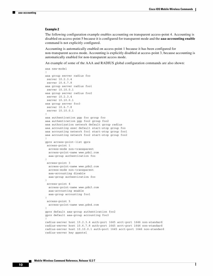
Example 2
The following configuration example enables accounting on transparent access-point 4. Accounting is disabled on access-point 5 because it is configured for transparent mode and the aaa-accounting enable command is not explicitly configured.
Accounting is automatically enabled on access-point 1 because it has been configured for non-transparent access mode. Accounting is explicitly disabled at access-point 3, because accounting is automatically enabled for non-transparent access mode.
An example of some of the AAA and RADIUS global configuration commands are also shown:
aaa new-model!aaa group server radius fooserver 10.2.3.4server 10.6.7.8
aaa group server radius foo1server 10.10.0.1
aaa group server radius foo2server 10.2.3.4server 10.10.0.1
aaa group server foo3server 10.6.7.8server 10.10.0.1
!aaa authentication ppp foo group fooaaa authentication ppp foo2 group foo2aaa authorization network default group radius aaa accounting exec default start-stop group fooaaa accounting network foo1 start-stop group foo1aaa accounting network foo2 start-stop group foo2!gprs access-point-list gprsaccess-point 1access-mode non-transparentaccess-point-name www.pdn1.comaaa-group authentication foo
!access-point 3access-point-name www.pdn2.comaccess-mode non-transparentaaa-accounting disableaaa-group authentication foo
!access-point 4access-point-name www.pdn3.comaaa-accounting enableaaa-group accounting foo1
!access-point 5access-point-name www.pdn4.com
!gprs default aaa-group authentication foo2gprs default aaa-group accounting foo3!radius-server host 10.2.3.4 auth-port 1645 acct-port 1646 non-standardradius-server host 10.6.7.8 auth-port 1645 acct-port 1646 non-standardradius-server host 10.10.0.1 auth-port 1645 acct-port 1646 non-standardradius-server key ggsntel
10Mobile Wireless Command Reference, Release 12.3 T
Cisco IOS Mobile Wireless Commandsaaa-accounting
Related Commands Command Description
aaa accounting Enables AAA accounting of requested services for billing or security purposes.
aaa authorization Sets parameters that restrict user access to a network.
aaa group server Groups different server hosts into distinct lists and distinct methods.
aaa-group Specifies a RADIUS server group and assigns the type of AAA services to be supported by the server group for a particular access point on the GGSN.
gprs default aaa-group Specifies a default RADIUS server group and assigns the type of AAA services to be supported by the server group for all access points on the GGSN.
radius-server host Specifies a RADIUS server host.
show gprs access-point Displays information about access points on the GGSN.
11Mobile Wireless Command Reference, Release 12.3 T

Cisco IOS Mobile Wireless Commandsaaa-group
aaa-groupTo specify a AAA server group and assign the type of AAA services to be supported by the server group for a particular access point on the GGSN, use the aaa-group access-point configuration command. To remove a AAA server group, use the no form of this command.
aaa-group {authentication | accounting} server-group
no aaa-group {authentication | accounting} server-group
Syntax Description
Defaults No default behavior or values.
Command Modes Access-point configuration
Command History
Usage Guidelines The Cisco Systems GGSN supports authentication and accounting at APNs using AAA server groups. By using AAA server groups, you gain the following benefits:
• You can selectively implement groups of servers for authentication and accounting at different APNs.
• You can configure different server groups for authentication services and accounting services in the same APN.
• You can control which RADIUS services you want to enable at a particular APN, such as AAA accounting.
authentication Assigns the selected server group for authentication services on the APN.
accounting Assigns the selected server group for accounting services only on the APN.
server-group Specifies the name of a AAA server group to be used for AAA services on the APN.
Note The name of the AAA server group that you specify must correspond to a server group that you configure using the aaa group server command.
Release Modification
12.2(4)MX This command was introduced.
12.2(8)YD This command was incorporated in Cisco IOS Release 12.2(8)YD.
12.2(8)B This command was incorporated in Cisco IOS Release 12.2(8)B.
12.3(4)T This command was incorporated in Cisco IOS Release 12.3(4)T.
12.3(8)T This command was incorporated in Cisco IOS Release 12.3(8)T.
12Mobile Wireless Command Reference, Release 12.3 T

Cisco IOS Mobile Wireless Commandsaaa-group
The GGSN supports the implementation of AAA server groups at both the global and access-point configuration levels. You can minimize your configuration by specifying the configuration that you want to support across most APNs, at the global configuration level. Then, at the access-point configuration level, you can selectively modify the services and server groups that you want to support at a particular APN. Therefore, you can override the AAA server global configuration at the APN configuration level.
To configure a default AAA server group to be used for all APNs on the GGSN, use the gprs default aaa-group global configuration command. To specify a different AAA server group to be used at a particular APN for authentication or accounting, use the aaa-group access-point configuration command.
If accounting is enabled on the APN, then the GGSN looks for an accounting server group to be used for the APN in the following order:
• First, at the APN for an accounting server group—configured in the aaa-group accounting command.
• Second, for a global GPRS default accounting server group—configured in the gprs default aaa-group accounting command.
• Third, at the APN for an authentication server group—configured in the aaa-group authentication command.
• Last, for a global GPRS default authentication server group—configured in the gprs default aaa-group authentication command.
If none of the above commands are configured on the GGSN, then AAA accounting is not performed.
If authentication is enabled on the APN, then the GGSN first looks for an authentication server group at the APN, configured in the aaa-group authentication command. If an authentication server group is not found at the APN, then the GGSN looks for a globally configured, GPRS default authentication server group, configured in the gprs default aaa-group authentication command.
To complete the configuration, you also must specify the following configuration elements on the GGSN:
• Enable AAA services using the aaa new-model global configuration command.
• Configure the RADIUS servers using the radius-server host command.
• Define a server group with the IP addresses of the RADIUS servers in that group using the aaa group server global configuration command.
• Configure the following AAA services:
– AAA authentication using the aaa authentication global configuration command
– AAA authorization using the aaa authorization global configuration command
– AAA accounting using the aaa accounting global configuration command
• Enable the type of AAA services (accounting and authentication) to be supported on the APN.
– The GGSN enables accounting by default for non-transparent APNs.
You can enable or disable accounting services at the APN using the aaa-accounting command.
– Authentication is enabled by default for non-transparent APNs. There is not any specific command to enable or disable authentication. Authentication cannot be enabled for transparent APNs.
You can verify the AAA server groups that are configured for an APN using the show gprs access-point command.
13Mobile Wireless Command Reference, Release 12.3 T
Cisco IOS Mobile Wireless Commandsaaa-group
Note For more information about AAA and RADIUS global configuration commands, see the Cisco IOS Security Command Reference.
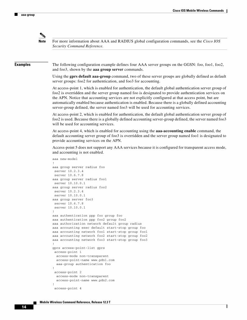
Examples The following configuration example defines four AAA server groups on the GGSN: foo, foo1, foo2, and foo3, shown by the aaa group server commands.
Using the gprs default aaa-group command, two of these server groups are globally defined as default server groups: foo2 for authentication, and foo3 for accounting.
At access-point 1, which is enabled for authentication, the default global authentication server group of foo2 is overridden and the server group named foo is designated to provide authentication services on the APN. Notice that accounting services are not explicitly configured at that access point, but are automatically enabled because authentication is enabled. Because there is a globally defined accounting server-group defined, the server named foo3 will be used for accounting services.
At access-point 2, which is enabled for authentication, the default global authentication server group of foo2 is used. Because there is a globally defined accounting server-group defined, the server named foo3 will be used for accounting services.
At access-point 4, which is enabled for accounting using the aaa-accounting enable command, the default accounting server group of foo3 is overridden and the server group named foo1 is designated to provide accounting services on the APN.
Access-point 5 does not support any AAA services because it is configured for transparent access mode, and accounting is not enabled.
aaa new-model!aaa group server radius fooserver 10.2.3.4server 10.6.7.8
aaa group server radius foo1server 10.10.0.1
aaa group server radius foo2server 10.2.3.4server 10.10.0.1
aaa group server foo3server 10.6.7.8server 10.10.0.1
!aaa authentication ppp foo group fooaaa authentication ppp foo2 group foo2aaa authorization network default group radius aaa accounting exec default start-stop group fooaaa accounting network foo1 start-stop group foo1aaa accounting network foo2 start-stop group foo2aaa accounting network foo3 start-stop group foo3!gprs access-point-list gprsaccess-point 1access-mode non-transparentaccess-point-name www.pdn1.comaaa-group authentication foo
!access-point 2access-mode non-transparentaccess-point-name www.pdn2.com
!access-point 4
14Mobile Wireless Command Reference, Release 12.3 T

Cisco IOS Mobile Wireless Commandsaaa-group
access-point-name www.pdn4.comaaa-accounting enableaaa-group accounting foo1
!access-point 5access-point-name www.pdn5.com
!gprs default aaa-group authentication foo2gprs default aaa-group accounting foo3!radius-server host 10.2.3.4 auth-port 1645 acct-port 1646 non-standardradius-server host 10.6.7.8 auth-port 1645 acct-port 1646 non-standardradius-server host 10.10.0.1 auth-port 1645 acct-port 1646 non-standardradius-server key ggsntel
Related Commands Command Description
aaa accounting Enables AAA accounting of requested services for billing or security purposes.
aaa authorization Sets parameters that restrict user access to a network.
aaa group server Groups different server hosts into distinct lists and distinct methods.
aaa-accounting Enables or disables accounting for a particular access point on the GGSN.
gprs default aaa-group Specifies a default RADIUS server group and assigns the type of AAA services to be supported by the server group for all access points on the GGSN.
radius-server host Specifies a RADIUS server host.
show gprs access-point Displays information about access points on the GGSN.
15Mobile Wireless Command Reference, Release 12.3 T
Cisco IOS Mobile Wireless Commandsaccess-mode
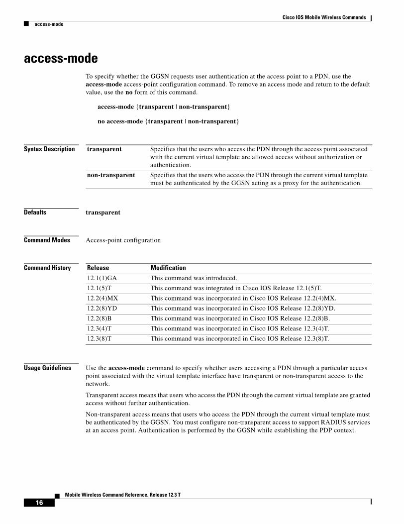
access-modeTo specify whether the GGSN requests user authentication at the access point to a PDN, use the access-mode access-point configuration command. To remove an access mode and return to the default value, use the no form of this command.
access-mode {transparent | non-transparent}
no access-mode {transparent | non-transparent}
Syntax Description
Defaults transparent
Command Modes Access-point configuration
Command History
Usage Guidelines Use the access-mode command to specify whether users accessing a PDN through a particular access point associated with the virtual template interface have transparent or non-transparent access to the network.
Transparent access means that users who access the PDN through the current virtual template are granted access without further authentication.
Non-transparent access means that users who access the PDN through the current virtual template must be authenticated by the GGSN. You must configure non-transparent access to support RADIUS services at an access point. Authentication is performed by the GGSN while establishing the PDP context.
transparent Specifies that the users who access the PDN through the access point associated with the current virtual template are allowed access without authorization or authentication.
non-transparent Specifies that the users who access the PDN through the current virtual template must be authenticated by the GGSN acting as a proxy for the authentication.
Release Modification
12.1(1)GA This command was introduced.
12.1(5)T This command was integrated in Cisco IOS Release 12.1(5)T.
12.2(4)MX This command was incorporated in Cisco IOS Release 12.2(4)MX.
12.2(8)YD This command was incorporated in Cisco IOS Release 12.2(8)YD.
12.2(8)B This command was incorporated in Cisco IOS Release 12.2(8)B.
12.3(4)T This command was incorporated in Cisco IOS Release 12.3(4)T.
12.3(8)T This command was incorporated in Cisco IOS Release 12.3(8)T.
16Mobile Wireless Command Reference, Release 12.3 T

Cisco IOS Mobile Wireless Commandsaccess-mode
Examples Example 1
The following example specifies non-transparent access to the PDN, gprs.pdn.com, through access-point 1:
interface virtual-template 1gprs access-point-list abc
!gprs access-point-list abcaccess-point 1access-point-name gprs.pdn.comaccess-mode non-transparent
Example 2
The following example specifies transparent access to the PDN, gprs.pdn2.com, through access-point 2:
interface virtual-template 1gprs access-point-list abc
!gprs access-point-list abcaccess-point 2access-point-name gprs.pdn2.com
Note Because transparent is the default access mode, it does not appear in the output of the show running-configuration command for the access point.
Related Commands Command Description
aaa-group Specifies a AAA server group and assigns the type of AAA services to be supported by the server group for a particular access point on the GGSN.
access-point Specifies an access-point number and enters access-point configuration mode.
gprs default aaa-group Specifies a default AAA server group and assigns the type of AAA services to be supported by the server group for all access points on the GGSN.
17Mobile Wireless Command Reference, Release 12.3 T

Cisco IOS Mobile Wireless Commandsaccess-point
access-pointTo specify an access point number and enter access-point configuration mode, use the access-point access-point list configuration command. To remove an access point number, use the no form of this command.
access-point access-point-index
no access-point access-point-index
Syntax Description
Defaults No default behavior or values.
Command Modes Access-point list configuration
Command History
Usage Guidelines Use the access-point command to create an access point to a PDN.
To configure an access point, first set up an access-point list using the gprs access-point-list command and then add the access point to the access-point list.
You can specify access point numbers in any sequence.
Note Memory constraints might occur if you define a large number of access points to support VPN Routing and Forwarding (VRF).
Examples The following example configures an access point with an index number of 7 in an access-point-list named “abc” on the GGSN:
gprs access-point-list abcaccess-point 7
access-point-index Integer from 1 to 65535 that identifies a GPRS access point.
Release Modification
12.1(1)GA This command was introduced.
12.1(5)T This command was integrated in Cisco IOS Release 12.1(5)T.
12.2(4)MX This command was incorporated in Cisco IOS Release 12.2(4)MX.
12.2(8)YD This command was incorporated in Cisco IOS Release 12.2(8)YD.
12.2(8)B This command was incorporated in Cisco IOS Release 12.2(8)B.
12.3(4)T This command was incorporated in Cisco IOS Release 12.3(4)T.
12.3(8)T This command was incorporated in Cisco IOS Release 12.3(8)T.
18Mobile Wireless Command Reference, Release 12.3 T

Cisco IOS Mobile Wireless Commandsaccess-point
Related Commands Command Description
access-point-name Specifies the network (or domain) name for a PDN that users can access from the GGSN at a defined access point.
gprs access-point-list Configures an access point list that you use to define PDN access points on the GGSN.
19Mobile Wireless Command Reference, Release 12.3 T
Cisco IOS Mobile Wireless Commandsaccess-point-name
access-point-nameTo specify the network (or domain) name for a PDN that users can access from the GGSN at a defined access point, use the access-point-name access-point configuration command. To remove an access point name, use the no form of this command.
access-point-name apn-name
no access-point-name apn-name
Syntax Description
Defaults There is no default value for this command.
Command Modes Access-point configuration
Command History
Usage Guidelines Use the access-point-name command to specify the PDN name of a network that can be accessed through a particular access point. An access-point name is mandatory for each access point.
To configure an access point, first set up an access-point list using the gprs access-point-list command and then add the access point to the access-point list.
The access-point name typically is the domain name of the service provider that users access, for example, www.isp.com.
Examples The following example specifies the access-point name for a network:
access-point 1access-point-name www.isp.comexit
apn-name Specifies the network or domain name of the private data network that can be accessed through the current access point.
Release Modification
12.1(1)GA This command was introduced.
12.1(5)T This command was integrated in Cisco IOS Release 12.1(5)T.
12.2(4)MX This command was incorporated in Cisco IOS Release 12.2(4)MX.
12.2(8)YD This command was incorporated in Cisco IOS Release 12.2(8)YD.
12.2(8)B This command was incorporated in Cisco IOS Release 12.2(8)B.
12.3(4)T This command was incorporated in Cisco IOS Release 12.3(4)T.
12.3(8)T This command was incorporated in Cisco IOS Release 12.3(8)T.
20Mobile Wireless Command Reference, Release 12.3 T

Cisco IOS Mobile Wireless Commandsaccess-point-name
Related Commands Command Description
access-point Specifies an access point number and enters access-point configuration mode.
21Mobile Wireless Command Reference, Release 12.3 T
Cisco IOS Mobile Wireless Commandsaccess-type
access-typeTo specify whether an access point is real or virtual on the GGSN, use the access-type access-point configuration command. To return to the default value, use the no form of this command.
access-type {virtual | real}
no access-type {virtual | real}
Syntax Description
Defaults real
Command Modes Access-point configuration
Command History
Usage Guidelines Use the access-type command to specify whether an access point is real or virtual on the GGSN. You only need to configure this command for virtual access types.
Virtual access types are used to configure virtual APN support on the Cisco Systems GGSN to minimize provisioning issues in other GPRS network entities that require configuration of APN information. Using the virtual APN feature on the Cisco Systems GGSN, HLR subscription data can simply provide the name of the virtual APN. User’s can still request access to specific target networks that are accessible by the GGSN without requiring each of those destination APNs to be provisioned at the HLR.
The default keyword, real, identifies a physical target network that the GGSN can reach. Real APNs must always be configured on the GGSN to reach external networks. Virtual APNs can be configured in addition to real access points to ease provisioning in the GPRS PLMN.
No other access-point configuration commands are applicable if the access type is virtual.
Examples The following example shows configuration of a virtual access point type and a real access point type:
access-point 1access-point-name corporate
virtual Specifies an APN type that is not associated with any specific physical target network on the GGSN.
real Specifies an APN type that corresponds to an external physical network to a PDN on the GGSN. This is the default value.
Release Modification
12.2(4)MX This command was introduced.
12.2(8)YD This command was incorporated in Cisco IOS Release 12.2(8)YD.
12.2(8)B This command was incorporated in Cisco IOS Release 12.2(8)B.
12.3(4)T This command was incorporated in Cisco IOS Release 12.3(4)T.
12.3(8)T This command was incorporated in Cisco IOS Release 12.3(8)T.
22Mobile Wireless Command Reference, Release 12.3 T
Cisco IOS Mobile Wireless Commandsaccess-type
access-type virtualexit
access-point 2access-point-name corporatea.comip-address-pool dhcp-clientdhcp-server 10.21.21.1
Related Commands Command Description
access-point Specifies an access point number and enters access-point configuration mode.
access-point-name Specifies the network (or domain) name for a PDN that users can access from the GGSN at a defined access point.
23Mobile Wireless Command Reference, Release 12.3 T

Cisco IOS Mobile Wireless Commandsaccess-violation deactivate-pdp-context
access-violation deactivate-pdp-contextTo specify that a user’s session be ended and the user packets discarded when a user attempts unauthorized access to a PDN through an access point, use the access-violation deactivate-pdp-context command. To return to the default value, use the no form of this command.
access-violation deactivate-pdp-context
no access-violation deactivate-pdp-context
Syntax Description This command has no arguments or keywords.
Defaults The user’s session remains active and the user packets are discarded.
Command Modes Access-point configuration
Command History
Usage Guidelines Use the access-violation deactivate-pdp-context command to specify the action that is taken if a user attempts unauthorized access through the specified access point.
The default is that the GGSN simply drops user packets when an unauthorized access is attempted. However, if you specify access-violation deactivate-pdp-context, the GGSN terminates the user’s session in addition to discarding the packets.
Examples The following example shows deactivation of a user’s access in addition to discarding the user packets:
access-point 1access-point-name pdn.aaaa.comip-access-group 101 inaccess-violation deactivate-pdp-contextexit
Release Modification
12.1(1)GA This command was introduced.
12.1(5)T This command was integrated in Cisco IOS Release 12.1(5)T.
12.2(4)MX This command was incorporated in Cisco IOS Release 12.2(4)MX.
12.2(8)YD This command was incorporated in Cisco IOS Release 12.2(8)YD.
12.2(8)YW This command was incorporated in Cisco IOS Release 12.2(8)YW and the discard-packets option was removed.
12.2(8)YY This command was incorporated in Cisco IOS Release 12.2(8)YY.
12.3(4)T This command was incorporated in Cisco IOS Release 12.3(4)T.
12.3(8)T This command was incorporated in Cisco IOS Release 12.3(8)T.
24Mobile Wireless Command Reference, Release 12.3 T

Cisco IOS Mobile Wireless Commandsaccess-violation deactivate-pdp-context
Related Commands Command Description
access-point-name Specifies the network (or domain) name for a PDN that users can access from the GGSN at a defined access point.
25Mobile Wireless Command Reference, Release 12.3 T
Cisco IOS Mobile Wireless Commandsaggregate
aggregateTo configure the GGSN to create an aggregate route in its IP routing table, when receiving PDP requests from MSs on the specified network, for a particular access point on the GGSN, use the aggregate access-point configuration command. To remove an aggregate route, use the no form of this command.
aggregate {auto | ip-network-prefix{/mask-bit-length | ip-mask}}
no aggregate {auto | ip-network-prefix{/mask-bit-length | ip-mask}}
Syntax Description
Defaults No default behavior or values.
Command Modes Access-point configuration
Command History
Usage Guidelines The GGSN uses a static host route to forward user data packets received from the Gi interface to the Gn interface using the virtual template interface of the GTP tunnel.
Without the aggregate command or gprs default aggregate command, the GGSN creates a static host route for each PDP context. For example, for 45,000 PDP contexts supported, the GGSN creates 45,000 static host routes in its IP routing table.
auto IP address mask sent by the DHCP or RADIUS server is used by the access point for route aggregation.
ip-network-prefix Dotted decimal notation of the IP network address to be used by the GGSN for route aggregation, in the format a.b.c.d.
/mask-bit-length Number of bits (as an integer) that represent the network portion of the specified IP network address. A forward slash is required before the integer.
Note There is no space between the ip-network-prefix and the slash (/).
ip-mask Dotted decimal notation of the IP network mask (in the format e.f.g.h.), which represents the network and host portion of the specified IP network address.
Release Modification
12.2(4)MX This command was introduced.
12.2(8)YD This command was incorporated in Cisco IOS Release 12.2(8)YD.
12.2(8)B This command was incorporated in Cisco IOS Release 12.2(8)B.
12.3(4)T This command was incorporated in Cisco IOS Release 12.3(4)T.
12.3(8)T This command was incorporated in Cisco IOS Release 12.3(8)T.
26Mobile Wireless Command Reference, Release 12.3 T

Cisco IOS Mobile Wireless Commandsaggregate
You can use the aggregate command to reduce the number of static routes implemented by the GGSN for PDP contexts at a particular access point. The aggregate command allows you to specify an IP network prefix to combine the routes of PDP contexts from the same network as a single route on the GGSN.
To configure the GGSN to automatically aggregate routes that are returned by a DHCP or RADIUS server, use the aggregate auto command at the APN. Automatic route aggregation can be configured at the access-point configuration level only on the GGSN. The gprs default aggregate global configuration command does not support the auto option; therefore, you cannot configure automatic route aggregation globally on the GGSN.
You can specify multiple aggregate commands at each access point to support multiple network aggregates. However, if you use the aggregate auto command at the APN, you cannot specify any other aggregate route ranges at the APN. If you need to handle other static route cases at the APN, then you will have to use the gprs default aggregate global configuration command.
To globally define an aggregate IP network address range for all access points on the GGSN for statically derived addresses, you can use the gprs default aggregate command. Then, you can use the aggregate command to override this default address range at a particular access point.
The GGSN responds in the following manner to manage routes for MSs through an access point, when route aggregation is configured in the following scenarios:
• No aggregation is configured on the GGSN, at the APN or globally—The GGSN inserts the 32-bit host route of the MS into its routing table as a static route.
• A default aggregate route is configured globally, but no aggregation is configured at the APN:
– If a statically or dynamically derived address for an MS matches the default aggregate route range, the GGSN inserts an aggregate route into its routing table.
– If the MS address does not match the default aggregate route, the GGSN inserts the 32-bit host route as a static route into the routing table.
• A default aggregate route is configured globally, and automatic route aggregation is configured at the APN:
– If a statically derived address for an MS matches the default aggregate route range, the GGSN inserts an aggregate route into its routing table.
– If a statically derived address for an MS does not match the default aggregate route, the GGSN inserts the 32-bit host route as a static route into its routing table.
– If a dynamically derived address for an MS is received, the GGSN aggregates the route based on the address and mask returned by the DHCP or RADIUS server.
• A default aggregate route is configured globally, and an aggregate route is also configured at the APN:
– If a statically or dynamically derived address for an MS matches the aggregate range at the APN through which it was processed, or otherwise matches the default aggregate range, the GGSN inserts an aggregate route into its routing table.
– If a statically or dynamically derived address for an MS does not match either the aggregate range at the APN, or the global default aggregate range, the GGSN inserts the 32-bit host route as a static route into its routing table.
Use care when assigning IP addresses to an MS before you configure the aggregation ranges on the GGSN. A basic guideline is to aggregate as many addresses as possible, but to minimize your use of aggregation with respect to the total amount of IP address space being used by the access point.
27Mobile Wireless Command Reference, Release 12.3 T

Cisco IOS Mobile Wireless Commandsaggregate
Note The aggregate command and gprs default aggregate commands affect routing on the GGSN. Use care when planning and configuring IP address aggregation.
Use the show gprs access-point command to display information about the aggregate routes that are configured on the GGSN. The aggregate output field appears only when aggregate routes have been configured on the GGSN, or the auto option is configured.
Use the show ip route command to verify whether the static route is in the current IP routing table on the GGSN. The static route created for any PDP requests (aggregated or non-aggregated) appears with the code “U” in the routing table indicating a per-user static route.
Note The show ip route command only displays a static route for aggregated PDP contexts if PDP contexts on that network have been created on the GGSN. If you configure route aggregation on the GGSN, but no PDP requests have been received for that network, the static route does not appear.
Examples Example 1
The following example specifies two aggregate network address ranges for access point 8. The GGSN will create aggregate routes for PDP context requests received from MSs with IP addresses on the networks 172.16.0.0 and 10.0.0.0:
gprs access-point-list gprsaccess-point 8
access-point-name pdn.aaaa.comaggregate 172.16.0.0/16aggregate 10.0.0.0/8
Note Regardless of the format in which you configure the aggregate command, the output from the show running-configuration command always displays the network in the dotted decimal/integer notation.
Example 2
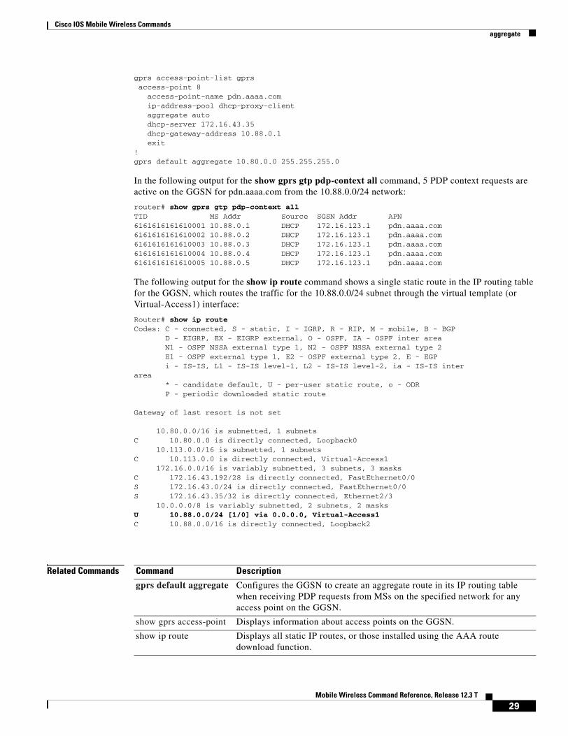
The following example shows a route aggregation configuration for access point 8 using DHCP on the GGSN, along with the associated output from the show gprs gtp pdp-context all command and the show ip route commands.
Notice that the aggregate auto command is configured at the access point where DHCP is being used. The dhcp-gateway-address command specifies the subnet addresses to be returned by the DHCP server. This address should match the IP address of a loopback interface on the GGSN. In addition, to accommodate route aggregation for another subnet 10.80.0.0, the gprs default aggregate global configuration command is used.
In this example, the GGSN aggregates routes for dynamically derived addresses for MSs through access point 8 based upon the address and mask returned by the DHCP server. For PDP context requests received for statically derived addresses on the 10.80.0.0 network, the GGSN also implements an aggregate route into its routing table, as configured by the gprs default aggregate command.
interface Loopback0ip address 10.80.0.1 255.255.255.255
!interface Loopback2ip address 10.88.0.1 255.255.255.255
!
28Mobile Wireless Command Reference, Release 12.3 T
Cisco IOS Mobile Wireless Commandsaggregate
gprs access-point-list gprsaccess-point 8
access-point-name pdn.aaaa.comip-address-pool dhcp-proxy-clientaggregate autodhcp-server 172.16.43.35dhcp-gateway-address 10.88.0.1exit
!gprs default aggregate 10.80.0.0 255.255.255.0
In the following output for the show gprs gtp pdp-context all command, 5 PDP context requests are active on the GGSN for pdn.aaaa.com from the 10.88.0.0/24 network:
router# show gprs gtp pdp-context allTID MS Addr Source SGSN Addr APN6161616161610001 10.88.0.1 DHCP 172.16.123.1 pdn.aaaa.com6161616161610002 10.88.0.2 DHCP 172.16.123.1 pdn.aaaa.com6161616161610003 10.88.0.3 DHCP 172.16.123.1 pdn.aaaa.com6161616161610004 10.88.0.4 DHCP 172.16.123.1 pdn.aaaa.com6161616161610005 10.88.0.5 DHCP 172.16.123.1 pdn.aaaa.com
The following output for the show ip route command shows a single static route in the IP routing table for the GGSN, which routes the traffic for the 10.88.0.0/24 subnet through the virtual template (or Virtual-Access1) interface:
Router# show ip routeCodes: C - connected, S - static, I - IGRP, R - RIP, M - mobile, B - BGP D - EIGRP, EX - EIGRP external, O - OSPF, IA - OSPF inter area N1 - OSPF NSSA external type 1, N2 - OSPF NSSA external type 2 E1 - OSPF external type 1, E2 - OSPF external type 2, E - EGP i - IS-IS, L1 - IS-IS level-1, L2 - IS-IS level-2, ia - IS-IS interarea * - candidate default, U - per-user static route, o - ODR P - periodic downloaded static route
Gateway of last resort is not set
10.80.0.0/16 is subnetted, 1 subnetsC 10.80.0.0 is directly connected, Loopback0 10.113.0.0/16 is subnetted, 1 subnetsC 10.113.0.0 is directly connected, Virtual-Access1 172.16.0.0/16 is variably subnetted, 3 subnets, 3 masksC 172.16.43.192/28 is directly connected, FastEthernet0/0S 172.16.43.0/24 is directly connected, FastEthernet0/0S 172.16.43.35/32 is directly connected, Ethernet2/3 10.0.0.0/8 is variably subnetted, 2 subnets, 2 masksU 10.88.0.0/24 [1/0] via 0.0.0.0, Virtual-Access1C 10.88.0.0/16 is directly connected, Loopback2
Related Commands Command Description
gprs default aggregate Configures the GGSN to create an aggregate route in its IP routing table when receiving PDP requests from MSs on the specified network for any access point on the GGSN.
show gprs access-point Displays information about access points on the GGSN.
show ip route Displays all static IP routes, or those installed using the AAA route download function.
29Mobile Wireless Command Reference, Release 12.3 T
Cisco IOS Mobile Wireless Commandsanonymous user
anonymous userTo configure anonymous user access at an access point, use the anonymous user access-point configuration command. To remove the username configuration, use the no form of this command.
anonymous user username [password]
no anonymous user username [password]
Syntax Description
Defaults No default behavior or values.
Command Modes Access-point configuration
Command History
Usage Guidelines Use this command to allow a mobile station (MS) to access a non-transparent mode APN without supplying the username and password in the GTP protocol configuration option (PCO) information element (IE) of the create PDP context request message. The GGSN will use the username and password configured on the APN for the user session.
This command enables anonymous access, which means that a PDP context can be created by an MS to a specific host without specifying a username and password.
Examples The following example specifies the username george and the password abcd123 for anonymous access at access point 49:
gprs access-point-list abcaccess-point 49
access-point-name www.pdn.comanonymous user george abcd123
username Alphanumeric string identifying user. The username argument can be only one word. It can contain any combination of numbers and characters.
password Alphanumeric string. The password argument can be only one word. It can contain any combination of numbers and characters.
Release Modification
12.2(4)MX This command was introduced.
12.2(8)YD This command was incorporated in Cisco IOS Release 12.2(8)YD.
12.2(8)B This command was incorporated in Cisco IOS Release 12.2(8)B.
12.3(4)T This command was incorporated in Cisco IOS Release 12.3(4)T.
12.3(8)T This command was incorporated in Cisco IOS Release 12.3(8)T.
30Mobile Wireless Command Reference, Release 12.3 T

Cisco IOS Mobile Wireless Commandsblock count
block countTo lock out group members for a length of time after a set number of incorrect passwords, use the block count command in local RADIUS server group configuration mode. To remove the user block after invalid login attempts, use the no form of this command.
block count count time {seconds | infinite}
no block count count time {seconds | infinite}
Syntax Description
Defaults No default behavior or values
Command Modes Local RADIUS server group configuration
Command History
Usage Guidelines If a setting of infinite is entered, an administrator must manually unblock the locked username.
Examples The following command locks out group members for 120 seconds after 3 incorrect passwords are entered:
block count 3 time 120
Related Commands
count Number of failed passwords that triggers a lockout.
time Time that the lockout should last.
seconds Number of seconds that the lockout should last.
infinite Length of time for the lockout is indefinite until an administrator manually unblocks the locked username.
Release Modification
12.2(11)JA This command was introduced on Cisco Aironet Access Point 1100 and Cisco Aironet Access Point 1200.
12.3(11)T This command was implemented on the following platforms: Cisco 2600XM, Cisco 2691, Cisco 2811, Cisco 2821, Cisco 2851, Cisco 3700, and Cisco 3800 series routers.
Command Description
clear radius local-server
Clears the statistics display or unblocks a user.
debug radius local-server
Displays the debug information for the local server.
31Mobile Wireless Command Reference, Release 12.3 T

Cisco IOS Mobile Wireless Commandsblock count
group Enters user group configuration mode and configures shared setting for a user group.
nas Adds an access point or router to the list of devices that use the local authentication server.
radius-server host Specifies the remote RADIUS server host.
radius-server local Enables the access point or router to be a local authentication server and enters into configuration mode for the authenticator.
reauthentication time Specifies the time (in seconds) after which access points or wireless-aware routers must reauthenticate the members of a group.
show radius local-server statistics
Displays statistics for a local network access server.
ssid Specifies up to 20 SSIDs to be used by a user group.
user Authorizes a user to authenticate using the local authentication server.
vlan Specifies a VLAN to be used by members of a user group.
Command Description
32Mobile Wireless Command Reference, Release 12.3 T

Cisco IOS Mobile Wireless Commandsblock-foreign-ms
block-foreign-msTo restrict GPRS access based on the mobile user’s home PLMN, use the block-foreign-ms access-point configuration command. To disable blocking of foreign subscribers, use the no form of this command.
block-foreign-ms
no block-foreign-ms
Syntax Description This command has no arguments or keywords.
Defaults Disabled
Command Modes Access-point configuration
Command History
Usage Guidelines The block-foreign-ms command enables the GGSN to block foreign MSs from accessing the GGSN.
When you use this command, the GGSN determines if an MS is inside or outside of the PLMN based on the mobile country code (MCC) and mobile network code (MNC). The MCC and MNC are specified using the gprs mcc mnc command.
Examples The following example blocks access to foreign MSs at access point 49:
gprs access-point-list abcaccess-point 49
access-point-name www.pdn.comblock-foreign-ms
Related Commands
Release Modification
12.2(8)YD This command was introduced.
12.2(8)B This command was incorporated in Cisco IOS Release 12.2(8)B.
12.3(4)T This command was incorporated in Cisco IOS Release 12.3(4)T.
12.3(8)T This command was incorporated in Cisco IOS Release 12.3(8)T.
Command Description
gprs mcc mnc Configures the mobile country code and mobile network code that the GGSN uses to determine whether a create PDP context request is from a foreign MS.
33Mobile Wireless Command Reference, Release 12.3 T
Cisco IOS Mobile Wireless Commandscdma pdsn a10 ahdlc engine
cdma pdsn a10 ahdlc engine To limit the number of Asynchronous High-Level Data Link Control (AHDLC) channel resources provided by the AHDLC engine, use the cdma pdsn a10 ahdlc engine command to in global configuration mode. To reset the number of AHDLC channel resources to the default, use the no form of this command.
cdma pdsn a10 ahdlc engine slot usable-channels usable-channels
no cdma pdsn a10 ahdlc engine slot usable-channels
Syntax Description
Defaults The default number of usable channels equals the maximum channels supported by the engine; the c-5 images supports 8000 sessions, and all c-6 image support 20000 sessions.
Command Modes Global configuration
Command History
Usage Guidelines If the value of usable-channels is greater than default maximum channels provided by the engine, the command will fail.
If the engine has any active channels, the command will fail.
Examples The following example limits the number of service channels provided by the AHDLC engine to 1000:
cdma pdsn a10 ahdlc engine 0 usable-channels 1000
Related Commands
slot Slot number of the AHDLC.
usable-channels usable-channels
Maximum number of channels that can be opened in the AHDLC engine. Valid values range between 0 and 8000 or 20000. Specifying 0 disables the engine.
Release Modification
12.2(2)XC This command was introduced.
12.2(8)BY The maximum number of usable channels was increased to 20000.
12.3(4)T This command was incorporated in Cisco IOS Release 12.3(4)T.
Command Description
debug cdma pdsn a10 ahdlc Displays debug messages for the AHDLC engine.
show cdma pdsn a10 ahdlc Displays information about the AHDLC engine.
show cdma pdsn resource Displays AHDLC resource information.
34Mobile Wireless Command Reference, Release 12.3 T

Cisco IOS Mobile Wireless Commandscdma pdsn a10 gre sequencing
cdma pdsn a10 gre sequencingTo enable inclusion of Generic Routing Encapsulation (GRE) sequence numbers in the packets sent over the A10 interface, use the cdma pdsn gre sequencing command in global configuration mode. To disable the inclusion of GRE sequence number in the packets sent over the A10 interface, use the no form of this command.
cdma pdsn a10 gre sequencing
no cdma pdsn a10 gre sequencing
Syntax Description This command has no arguments or keywords.
Defaults GRE sequence numbers are included in the packets sent over the A10 interface.
Command Modes Global configuration
Command History
Examples The following example instructs Cisco PDSN to include per-session GRE sequence numbers in the packets sent over the A10 interface:
cdma pdsn a10 gre sequencing
Related Commands
Release Modification
12.1(3)XS This command was introduced.
12.3(4)T This command was incorporated in Cisco IOS Release 12.3(4)T.
Command Description
debug cdma pdsn a10 gre Displays debug messages for A10 GRE interface errors.
show cdma pdsn pcf Displays information about PCFs that have R-P tunnels to the PDSN.
show cdma pdsn Displays the current status and configuration of the PDSN gateway.
35Mobile Wireless Command Reference, Release 12.3 T
Cisco IOS Mobile Wireless Commandscdma pdsn a10 init-ppp-after-airlink-start airlink-start-timeout
cdma pdsn a10 init-ppp-after-airlink-start airlink-start-timeoutTo configure the PDSN so that Point-to-Point Protocol (PPP) negotiation with an MN will start only after the traffic channel is assigned, ( inother words, after a Registration Request with airlink-start is received), use the cdma pdsn a10 init-ppp-after-airlink-start command in global configuration mode. Use the no form of this command to revert to the default behavior.
cdma pdsn a10 init-ppp-after-airlink-start airlink-start-timeout 1-120
no cdma pdsn a10 init-ppp-after-airlink-start airlink-start-timeout 1-120
Syntax Description
Defaults By default, this CLI is not enabled, therefore, the PDSN will initiate PPP negotiation immediately after a Registration Reply is sent to the initial Registration.Request.
When enabled, the default timeout interval is 10 seconds.
Command Modes Global configuration
Command History
Usage Guidelines The PDSN initiates PPP negotiation immediately after a Registration Reply is sent to the initial Registration Request, but the calls (for which the PPP negotiation has started before the traffic channel is assigned to MN) have failed.
When this command is enabled, the PPP negotiation withthe MN will start only after the traffic channel is assigned—after a Registration Request with airlink-start is received. If the airlink start is not received at all, the session will be torn down when timeout occurs.By default, this timeout interval is 10 seconds, or can be configured through the CLI.
The session is not torn down immediately after the timeout, so, in order to minimize the impact on the performance, there is just one timer started to keep track of all the sessions waiting for airlink-start to start PPP.
For example, take the default of 10 seconds. If the timer expires at t1 and a new call comes at t2( t2 >t1), the next run of the timer will be at t1+10. It is likely that the uptime for the call is not more than 10 seconds since t2 > t1. So the call will be checked at the next next run (t1+10+10). That is , the variation is between 1 and 10.
Examples The following example illustrates the cdma pdsn a10 init-ppp-after-airlink-start airlink-start-timeout command:
router# cdma pdsn a10 init-ppp-after-airlink-start airlink-start-timeout 20
1-120 Sets the timeout interval before the session is torn down.
Release Modification
12.2(8)ZB4a This command was introduced.
12.3(4)T This command was incorporated in Cisco IOS Release 12.3(4)T.
36Mobile Wireless Command Reference, Release 12.3 T

Cisco IOS Mobile Wireless Commandscdma pdsn a10 init-ppp-after-airlink-start airlink-start-timeout
37Mobile Wireless Command Reference, Release 12.3 T

Cisco IOS Mobile Wireless Commandscdma pdsn a10 max-lifetime
cdma pdsn a10 max-lifetimeTo specify the maximum A10 registration lifetime accepted, use the cdma pdsn a10 max-lifetime command in global configuration mode. To return to the default length of time, use the no form of this command.
cdma pdsn a10 max-lifetime seconds
no cdma pdsn a10 max-lifetime
Syntax Description
Defaults 1800 seconds.
Command Modes Global configuration
Command History
Examples The following example specifies that the A10 interface will be maintained for 1440 seconds:
cdma pdsn a10 max-lifetime 1440
Related Commands
seconds Maximum A10 registration lifetime accepted by Cisco PDSN. The range is 1 to 65535 seconds. The default is 1800 seconds.
Release Modification
12.1(3)XS This command was introduced.
12.3(4)T This command was incorporated in Cisco IOS Release 12.3(4)T.
Command Description
cdma pdsn a10 gre sequencing Enables GRE sequence number checking on packets received over the A10 interface.
debug cdma pdsn a10 gre Displays debug messages for A10.
show cdma pdsn pcf Displays information about PCFs that have R-P tunnels to the PDSN.
show cdma pdsn Displays the current status and configuration of the PDSN gateway.
38Mobile Wireless Command Reference, Release 12.3 T

Cisco IOS Mobile Wireless Commandscdma pdsn a11 dormant ppp-idle-timeout send-termreq
cdma pdsn a11 dormant ppp-idle-timeout send-termreqTo specify that for dormant sessions, on ppp idle timeout, ppp termreq will be sent, use the cdma pdsn all dormant ppp-idle-timeout send-termreq command in global configuration mode. To disble this feature, use the no form of this command.
cdma pdsn all dormant ppp-idle-timeout send-termreq
no cdma pdsn all dormant ppp-idle-timeout send-termreq
Syntax Description There are no keywords or variable for this command.
Defaults There are no default values.
Command Modes Global configuration
Command History
Usage Guidelines Disabling this behaviour will avoid traffic channel allocation for cleaning up ppp sessions at the mobile.
Examples router# cdma pdsn a11 dormant ppp-idle-timeout send-termreq
Release Modification
12.2(8)ZB This command was introduced.
12.3(4)T This command was incorporated in Cisco IOS Release 12.3(4)T.
39Mobile Wireless Command Reference, Release 12.3 T

Cisco IOS Mobile Wireless Commandscdma pdsn a11 mandate presence airlink-setup
cdma pdsn a11 mandate presence airlink-setupTo mandate that the initial RRQ should have Airlink-Setup in Acct CVSE from PCF, use the cdma pdsn all mandate presence airlink-setup command in global configuration mode. To disable this feature, use the no form of this command.
cdma pdsn a11 mandate presence airlink-setup
no cdma pdsn a11 mandate presence airlink-setup
Syntax Description This command has no keywords or variables.
Defaults There are no default values.
Command Modes Global configuration
Command History
Usage Guidelines Issuing this command mandates that the initial RRQ should have Airlink-Setup in Acct CVSE from PCF. As a result, if this Airlink setup is not present in the RRQ, the session is not created, and a RRP with error code “86H - Poorly formed request” is returned.
If you do not configure this command, or disable it, then sessions can be opened even with no accounting CVSE being present in the initial RRQ.
Examples router# cdma pdsn a11 mandate presence airlink-setup
Release Modification
12.2(8)ZB1 This command was introduced.
12.3(4)T This command was incorporated in Cisco IOS Release 12.3(4)T.
40Mobile Wireless Command Reference, Release 12.3 T

Cisco IOS Mobile Wireless Commandscdma pdsn accounting local-timezone
cdma pdsn accounting local-timezoneTo specify the local time stamp for PDSN accounting events, use the cdma pdsn accounting local-timezone command in global configuration mode. To return to the default Universal Time (UTC), use the no form of this command.
cdma pdsn accounting local-timezone
no cdma pdsn accounting local-timezone
Syntax Description This command has no arguments or keywords.
Defaults UTC time, a standard based on GMT, is enabled.
Command Modes Global configuration
Command History
Usage Guidelines You must use the clock timezone hours-offset [minutes-offset] global configuration command to reflect the difference between local time and UTC time.
Examples The following example sets the local time in Korea:
clock timezone KOREA 9cdma pdsn accounting local-timezone
Related Commands
Release Modification
12.1(5)XS This command was introduced.
12.3(4)T This command was incorporated in Cisco IOS Release 12.3(4)T.
Command Description
clock timezone Specifies the hours and minutes (optional) difference between the local time zone and UTC.
cdma pdsn accounting send start-stop
Causes the PDSN to send:
• An Accounting Stop record when it receives an active stop airlink record (dormant state)
• An Accounting Start record when it receives an active start airlink record (active state)
41Mobile Wireless Command Reference, Release 12.3 T

Cisco IOS Mobile Wireless Commandscdma pdsn accounting send
cdma pdsn accounting sendTo cause the PDSN to send accounting records when the call transitions between active and dormant states, use the cdma pdsn accounting send start-stop command in global configuration mode. To stop sending accounting records, use the no form of this command.
cdma pdsn accounting send {start-stop | cdma-ip-tech}
no cdma pdsn accounting send {start-stop | cdma-ip-tech}
Syntax Description
Defaults No default behavior or values.
Command Modes Global configuration
Command History
Usage Guidelines When this feature is enabled, the PDSN will send:
• An Accounting Stop record when it receives an active stop airlink record (dormant state).
• An Accounting Start record when it receives an active start airlink record (active state).
Examples The following example starts sending PDSN accounting events:
cdma pdsn accounting send start-stop
Related Commands
Command Description
start-stop Informs the PDSN when to begin sending accounting records and when to stop sending them.
cdma-ip-tech Accounting records are generated with special IP-Tech number.
Release Modification
12.2(2)XC This command was introduced.
12.3(4)T This command was incorporated in Cisco IOS Release 12.3(4)T.
Command Description
cdma pdsn accounting local-timezone
Specifies the timestamp for PDSN accounting events.
cdma pdsn accounting time-of-day
Sets the accounting information for a specific time of day.
aaa accounting network pdsn start-stop group radius
Enables AAA accounting of requested services for billing or security purposes when you use RADIUS.
42Mobile Wireless Command Reference, Release 12.3 T
Cisco IOS Mobile Wireless Commandscdma pdsn accounting send cdma-ip-tech
cdma pdsn accounting send cdma-ip-techTo configure specific values for the F11 attribute for proxy Mobile IP and VPDN services, use the cdma pdsn accounting send cdma-ip-tech command in global configuration mode. To deconfigure those values, use the no form of this command.
cdma pdsn accounting send cdma-ip-tech [proxy-mobile-ip | vpdn]
no cdma pdsn accounting send cdma-ip-tech [proxy-mobile-ip | vpdn]
Syntax Description
Defaults No default behavior or values.
Command Modes Global configuration.
Command History
Examples pdsn(config)#cdma pdsn accounting send cdma-ip-tech proxy-mobile-ip 3pdsn(config)#cdma pdsn accounting send cdma-ip-tech vpdn 4
Command Description
proxy-mobile-ip Sets the IP-Tech proxy-mobile-ip number. Values are 3-65535.
vpdn Sets the IP-Tech vpdn number. Values are 3-65535.
Release Modification
12.1XC This command was introduced.
12.3(4)T This command was incorporated in Cisco IOS Release 12.3(4)T.
43Mobile Wireless Command Reference, Release 12.3 T
Cisco IOS Mobile Wireless Commandscdma pdsn accounting time-of-day
cdma pdsn accounting time-of-dayTo set the accounting information for specified times during the day, use the cdma pdsn accounting time-of-day command in global configuration mode. To disable the specification, use the no form of this command.
cdma pdsn accounting time-of-day hh:mm:ss
no cdma pdsn accounting time-of-day
Syntax Description
Defaults No default behavior or values.
Command Modes Global configuration
Command History
Usage Guidelines This command is used to facilitate billing when a user is charged different prices based upon the time of the day. Up to ten different accounting triggers can be configured.
Examples The following example sets an accounting trigger for 13:30:20:
cdma pdsn accounting time-of-day 13:30:30
Related Commands
hh:mm:ss Hour:minutes:seconds.
Release Modification
12.1(5)XS This command was introduced.
12.3(4)T This command was incorporated in Cisco IOS Release 12.3(4)T.
Command Description
clock set Sets the system clock.
debug cdma pdsn accounting time-of-day
Displays debug information for the command.
show clock Displays the system clock.
cdma pdsn accounting send start-stop
Causes the PDSN to send:
• An Accounting Stop record when it receives an active stop airlink record (dormant state)
• An Accounting Start record when it receives an active start airlink record (active state)
44Mobile Wireless Command Reference, Release 12.3 T

Cisco IOS Mobile Wireless Commandscdma pdsn age-idle-users
cdma pdsn age-idle-usersTo configure the aging of idle users, use the cdma pdsn age-idle-users command. To stop aging out idle users, use the no form of this command.
cdma pdsn age-idle-users [minimum-age value]
no cdma pdsn age-idle-users
Syntax Description
Defaults By default, no idle users are aged out.
Command Modes Global configuration
Command History
Usage Guidelines If no value is specified, the user that has been idle the longest will be aged out. If an age is specified and the user that has been idle the longest has not been idle for the specified value, then no users are aged out.
Examples The following example sets a minimum age out value of 5 seconds:
cdma pdsn age-idle-users minimum-age 5
minimum-age value (Optional) The minimum number of seconds a user should be idle before they are a candidate for being aged out. Possible values are 1 through 65535.
Release Modification
12.2(2)XC This command was introduced.
12.3(4)T This command was incorporated in Cisco IOS Release 12.3(4)T.
45Mobile Wireless Command Reference, Release 12.3 T

Cisco IOS Mobile Wireless Commandscdma pdsn cluster controller
cdma pdsn cluster controller To configure the PDSN to operate as a cluster controller, and to configure various parameters on the cluster controller, use the cdma pdsn cluster controller command. To disable certain cluster controller parameters, use the no form of this command.
cdma pdsn cluster controller [ interface interface-name | timeout seconds [window number] | window number ]
no cdma pdsn cluster controller [ interface interface-name | timeout seconds [window number] | window number ]
Syntax Description
Defaults The timeout default value is 300 seconds.
Command Modes Global configuration
Command History
Examples The following example enables the cdma cluster controller:
cdma pdsn cluster controller interface FastEthernet1/0
interface Interface name on which the cluster controller has IP connectivity to the cluster members.
timeout The time the cluster controller waits to seek a member when there is no reply from that cluster member. The range is between 10 and 300 seconds, and the default value is 300 seconds.
window number The number of sequential seek messages sent to a cluster member before it is presumed offline.
Release Modification
12.2(2)XC This command was introduced.
12.3(4)T This command was incorporated in Cisco IOS Release 12.3(4)T.
46Mobile Wireless Command Reference, Release 12.3 T
Cisco IOS Mobile Wireless Commandscdma pdsn cluster controller session-high
cdma pdsn cluster controller session-highTo generate an alarm when the controller reaches the upper threshold of the maximum number of sessions it can handle, use the cdma pdsn cluster member session-high command. To disable this feature, use the no form of this command.
cdma pdsn cluster controller session-high 1-1000000
no cdma pdsn cluster controller session-high 1-1000000
Syntax Description
Defaults The range is 1-1000000. The configured value should be more than the lower threshold value. The default value is 200000.
Command Modes Global configuration
Command History
Usage Guidelines You should take into account the number of members in the cluster when you configure the high threshold. For example, if there are only 2 members in the cluster, the high threshold should be less than 40000.
Examples The following example illustrates the cdma pdsn cluster contoller session-high command:
Received SNMPv1 Trap:Community: publicEnterprise: cCdmaPdsnMIBNotifPrefixAgent-addr: 9.15.72.15Enterprise Specific trap.Enterprise Specific trap: 8Time Ticks: 9333960cCdmaServiceAffectedLevel.0 = major(3)cCdmaClusterSessHighThreshold.0 = 50
1-1000000 The threshold of the maximum number of sessions the controller can handle.
Release Modification
12.2(8)ZB1 This command was introduced.
12.3(4)T This command was incorporated in Cisco IOS Release 12.3(4)T.
47Mobile Wireless Command Reference, Release 12.3 T

Cisco IOS Mobile Wireless Commandscdma pdsn cluster controller session-low
cdma pdsn cluster controller session-lowTo generate an alarm when the controller reaches the lower threshold of the sessions (hint to NOC that the system is being under utilized), use the cdma pdsn cluster member session-low command. To disable this feature, use the no form of this command.
cdma pdsn cluster controller session-low 1-1000000
no cdma pdsn cluster controller session-low 1-1000000
Syntax Description
Defaults The range is 0-999999. The configured value should be less than the upper threshold value. The default value is 190000.
Command Modes Global configuration
Command History
Usage Guidelines You should take into account the number of members in the cluster when you configure the low threshold.
Examples The following example illustrates the cdma pdsn cluster contoller session-low command:
Received SNMPv1 Trap:Community: publicEnterprise: cCdmaPdsnMIBNotifPrefixAgent-addr: 9.15.72.15Enterprise Specific trap.Enterprise Specific trap: 9Time Ticks: 9330691cCdmaServiceAffectedLevel.0 = major(3)cCdmaClusterSessLowThreshold.0 = 10
1-1000000 The threshold of the maximum number of sessions the controller can handle.
Release Modification
12.2(8)ZB1 This command was introduced.
12.3(4)T This command was incorporated in Cisco IOS Release 12.3(4)T.
48Mobile Wireless Command Reference, Release 12.3 T

Cisco IOS Mobile Wireless Commandscdma pdsn cluster member
cdma pdsn cluster member To configure the PDSN to operate as a cluster member, and to configure various parameters on the cluster member, use the cdma pdsn cluster member command. To disable certain cluster controller parameters, use the no form of this command.
cdma pdsn cluster member [ controller ipaddr | interface interface-name | prohibit type | timeout seconds [window number] | window number ]
no cdma pdsn cluster member [ controller ipadd | interface interface-name | timeout seconds [window number] | window number ]
Syntax Description
Defaults The default timeout value for the cluster member is 300 seconds.
Command Modes Global configuration
Command History
Usage Guidelines The prohibit field enables a member to administratively rid itself of its load without service interruption. When enabled, the member is no longer given any new data sessions by the controller.
Examples The following example enables a cdma pdsn cluster member:
cdma pdsn cluster member interface FastEthernet1/0
controller ipaddr The controller that a specific member is connected to, identified by the controller’s IP address.
interface Interface name on which the cluster controller has IP connectivity to the cluster members.
prohibit The type of traffic that the member is allowed to handle, or is prohibited from handling. Administratively prohibits member from accepting new data sessions within the cluster framework.
timeout The time the cluster controller waits to seek a member when there is no reply from that cluster member. The range is between 10 and 600 seconds, and the default value is 300 seconds.
window number The number of sequential seek messages sent to a cluster member before it is presumed offline.
Release Modification
12.2(2)XC This command was introduced.
12.3(4)T This command was incorporated in Cisco IOS Release 12.3(4)T.
49Mobile Wireless Command Reference, Release 12.3 T

Cisco IOS Mobile Wireless Commandscdma pdsn compliance iosv4.1 session-reference
cdma pdsn compliance iosv4.1 session-reference3GPP2 IOS version 4.2 mandates that the Session Reference ID in the A11 Registration Request is always set to 1. To configure the PDSN to interoperate with a PCF that is not compliant with 3GPP2 IOS version 4.2, use the cdma pdsn compliance iosv4.1 session-reference command inGlobal configuration mode. To disable this configuration, use the no form of this command.
cdma pdsn compliance iosv4.1 session-reference
no cdma pdsn compliance iosv4.1 session-reference
Syntax Description This command has no arguments or keywords.
Defaults Session Reference ID set to 1 in the A11 registration Request is on by default.
Command Modes Global configuration.
Command History
Examples The following command instructs the PDSN to skip any checks done on the session reference id of incoming Registration Requests to ensure that they are set to 1.
router # cdma pdsn compliance iosv4.1 session-reference
Related Commands
Release Modification
12.2(8)BY1 This command was introduced.
12.3(4)T This command was incorporated in Cisco IOS Release 12.3(4)T.
Command Description
debug cdma pdsn a11 Displays debug messages for A11 interface errors, events, and packets.
50Mobile Wireless Command Reference, Release 12.3 T

Cisco IOS Mobile Wireless Commandscdma pdsn compliance is835a esn-optional
cdma pdsn compliance is835a esn-optionalTo send an ESN value in accounting packets to the RADIUS server only if it has received an ESN value (A2) in the A11 RRQ from PCF, use the cdma pdsn compliance is835 esn-optional command in global configuration mode. To disable the specification, use the no form of this command.
cdma pdsn compliance is835 esn-optional
no cdma pdsn compliance is835 esn-optional
Syntax Description There are no keywords or arguments for this command.
Defaults The default behavior is to send the ESN attribute in all accounting records..
Command Modes Global configuration
Command History
Usage Guidelines If no A2 is received in the RRQ, the PDSN will not send the ESN attribute in the accounting record. This behavior is in accordance to IS835A.
If this command is not configured, the PDSN will send the ESN value regardless whether the A2 attribute value is received from PCF or not. This is in accordance to IS835B.
Release Modification
12.2(8)ZB4 This command was introduced.
12.3(4)T This command was incorporated in Cisco IOS Release 12.3(4)T.
51Mobile Wireless Command Reference, Release 12.3 T

Cisco IOS Mobile Wireless Commandscdma pdsn failure-history
cdma pdsn failure-historyTo configure CDMA PDSN SNMP session failure history size, use the cdma pdsn failure-history command in global configuration mode. To return to the default length of time, use the no form of this command.
cdma pdsn failure-history entries
no cdma pdsn failure-history
Syntax Description
Defaults No default behavior or values.
Command Modes Global configuration
Command History
Examples The following example specifies that 1000 is the maximum number of entries that can be recorded in the SNMP session table:
cdma pdsn failure-history 1000
Related Commands
entries Maximum number of entries that can be recorded in the SNMP session failure table. Possible values are 0 through 2000.
Release Modification
12.1(3)XS This command was introduced.
12.3(4)T This command was incorporated in Cisco IOS Release 12.3(4)T.
Command Description
snmp-server enable traps cdma Specifies the community access string to permit access to the SNMP protocol.
show cdma pdsn Displays the current status and configuration of the PDSN gateway.
52Mobile Wireless Command Reference, Release 12.3 T

Cisco IOS Mobile Wireless Commandscdma pdsn ingress-address-filtering
cdma pdsn ingress-address-filteringTo enable ingress address filtering, use the cdma pdsn ingress-address-filtering command in global configuration mode. To disable ingress address filtering, use the no form of this command.
cdma pdsn ingress-address-filtering
no cdma pdsn ingress-address-filtering
Syntax Description This command has no arguments or keywords.
Defaults Ingress address filtering is disabled.
Command Modes Global configuration
Command History
Usage Guidelines When this command is configured, the PDSN checks the source IP address of every packet received on the PPP link from the mobile station. If the address is not associated with the PPP link to the mobile station and is not an MIP RRQ or Agent Solicitation, then the PDSN discards the packet and sends a request to reestablish the PPP link.
Examples The following example enables ingress address filtering:
cdma pdsn ingress-address-filtering
Related Commands
Release Modification
12.1(3)XS This command was introduced.
12.3(4)T This command was incorporated in Cisco IOS Release 12.3(4)T.
Command Description
show cdma pdsn Displays the current status and configuration of the PDSN gateway.
show cdma pdsn session Displays the session information on the PDSN.
53Mobile Wireless Command Reference, Release 12.3 T

Cisco IOS Mobile Wireless Commandscdma pdsn maximum pcf
cdma pdsn maximum pcfTo set the maximum number of PCFs that can connect to a PDSN, use the cdma pdsn maximum pcf command in global configuration mode. To disable a configured limit, use the no form of this command.
cdma pdsn maximum pcf maxpcf
no cdma pdsn maximum pcf
Syntax Description
Defaults No default behavior or values.
Command Modes Global Configuration
Command History
Usage Guidelines If no maximum number of PCFs is configured, the only limitation is the amount of memory.
You can configure the maximum PCFs to be less than the existing PCFs. As a result, when you issue the show cdma pdsn command, you may see more existing PCFs than the configured maximum. It is the responsibility of the user to bring down the existing PCFs to match the configured maximum.
Examples The following example specifies that 200 PCFs can be sent:
cdma pdsn maximum pcf 200
Related Commands
maxpcf Maximum number of PCFs that can communicate with a PDSN. Possible values are 1 through 2000.
Release Modification
12.1(3)XS This command was introduced.
12.3(4)T This command was incorporated in Cisco IOS Release 12.3(4)T.
Command Description
show cdma pdsn Displays the current status and configuration of the PDSN gateway.
54Mobile Wireless Command Reference, Release 12.3 T

Cisco IOS Mobile Wireless Commandscdma pdsn maximum sessions
cdma pdsn maximum sessionsTo set the maximum number of mobile sessions allowed on a PDSN, use the cdma pdsn maximum sessions command in global configuration mode. To disable a configured limit, use the no form of this command.
cdma pdsn maximum sessions maxsessions
no cdma pdsn maximum sessions
Syntax Description
Defaults The c-5 images support 8000 sessions, and the c-6 images support 20000 sessions.
Command Modes Global Configuration.
Command History
Usage Guidelines If PDSN runs out of resources before the configured number is reached, then PDSN will reject the creation of further sessions.
You can configure the maximum sessions to be less than the existing sessions. As a result, when you issue the show cdma pdsn command, you may see more existing sessions than the configured maximum. It is the responsibility of the user to bring down the existing sessions to match the configured maximum.
Examples The following example sets the maximum number of mobile sessions to 100:
cdma pdsn maximum sessions 100
Related Commands
maxsessions Maximum number of mobile sessions allowed on a PDSN. Possible values depend on which image you are using.
Release Modification
12.1(3)XS This command was introduced.
12.2(8)BY The maximum number of mobile sessions was raised to 20000.
12.3(4)T This command was incorporated in Cisco IOS Release 12.3(4)T.
Command Description
show cdma pdsn session Displays PDSN session information.
55Mobile Wireless Command Reference, Release 12.3 T

Cisco IOS Mobile Wireless Commandscdma pdsn mobile-advertisement-burst
cdma pdsn mobile-advertisement-burst To configure the number and interval of Agent Advertisements that a PDSN FA can send, use the cdma pdsn mobile-advertisement-burst command in interface configuration mode. To reset the configuration to the defaults, use the no form of this command.
cdma pdsn mobile-advertisement-burst {number value | interval msec}
no cdma pdsn mobile-advertisement-burst {number | interval}
Syntax Description
Defaults The default number of agent advertisements to send is 5.
The default interval between advertisements is 200 milliseconds.
Command Modes Interface Configuration.
Command History
Usage Guidelines You must specify at least one of the optional parameters. Otherwise, the command has no effect. When virtual-access interfaces are created from the virtual template, default values will be used for any parameters not already configured on the virtual template.
This command should be configured on virtual templates only, and only when PDSN service is configured.
Examples The following example configures PDSN FA advertisement:
cdma pdsn mobile-advertisement-burst number 10 interval 500
Related Commands
number value The number of agent advertisements. Possible values are 1 through 10. The default is 5.
interval msec Specifies the interval, in milliseconds, between advertisements. Possible values are 50 through 500. The default is 200 milliseconds.
Release Modification
12.2(2)XC This command was introduced.
12.3(4)T This command was incorporated in Cisco IOS Release 12.3(4)T.
Command Description
ip mobile foreign-service challenge Configures the challenge timeout value and the number of valid recently-sent challenge values.
ip mobile foreign-service challenge forward-mfce
Enables the FA to forward MFCE and mobile station-AAA to the HA.
56Mobile Wireless Command Reference, Release 12.3 T

Cisco IOS Mobile Wireless Commandscdma pdsn msid-authentication
cdma pdsn msid-authenticationTo enable MSID-based authentication and access, use the cdma pdsn msid-authentication command in global configuration mode. To disable MSID-based authentication and access, use the no form of this command.
cdma pdsn msid-authentication [close-session-on-failure][imsi number] [irm number] [min number] [profile-password password]
no cdma pdsn msid-authentication
Syntax Description
Defaults MSID authentication is disabled. When enabled, the default values are as follows:
• imsi: 5
• irm: 4
• min: 6
• profile-password: cisco
Command Modes Global Configuration.
Command History
close-session-on-failure Closes the session if authorization fails.
imsi number (Optional) The number digits from the International Mobile Station Identifier (IMSI) that are to be used as the User-Name in the Access-Request for MSID authentication. Possible values are 1 to 15. The default is 5.
irm number (Optional) International Roaming Mobile Identification Number and the identifier used to retrieve the network profile from the RADIUS server. Possible values are 1 through 10. The default is 4.
min number (Optional) Mobile Identification Number and the identifier used to retrieve the network profile from the RADIUS server. Possible values are 1 through 10. The default is 6.
profile-password password (Optional) The AAA server access password for MSID-based authentication. The default is “cisco”.
Release Modification
12.1(3)XS This command was introduced.
12.2(2)XC The profile-password keyword was added.
12.2(8)ZB1 The close-session-on-failure keyword was added
12.3(4)T This command was incorporated in Cisco IOS Release 12.3(4)T.
57Mobile Wireless Command Reference, Release 12.3 T
Cisco IOS Mobile Wireless Commandscdma pdsn msid-authentication
Usage Guidelines MSID authentication provides Simple IP service for mobile stations that do not negotiate CHAP or PAP. Cisco PDSN retrieves a network profile based on the MSID from the RADIUS server. The network profile should include the internet realm of the home network that owns the MSID. Cisco PDSN constructs the NAI from the MSID and the realm. The constructed NAI is used in generated accounting records. If the PDSN is unable to obtain the realm, then it denies service to the mobile station.
The identifier used to retrieve the network profile from the RADIUS server depends on the format of the MSID, which can be one of the following:
• International Mobile Station Identity (IMSI)
• Mobile Identification Number (MIN)
• International Roaming MIN (IRM)
If the mobile station uses IMSI, the default identifier that PDSN uses to retrieve network profile is of the form IMSI-nnnnn where nnnnn is the first five digits of the IMSI. The number of digits from the IMSI to be used can be configured using the command cdma pdsn msid-authentication imsi.
If the mobile station uses MIN, the default identifier that PDSN uses to retrieve network profile is of the form MIN-nnnnnn where nnnnnn is the first six digits of the MIN. The number of digits from the MIN to be used can be configured using the command cdma pdsn msid-authentication min.
If the mobile station uses IRM, the default identifier that PDSN uses to retrieve network profile is of the form IRM-nnnn where nnnn is the first four digits of the IRM. The number of digits from the IRM to be used can be configured using the command cdma pdsn msid-authentication irm.
The realm should be defined in the network profile on the RADIUS user with the Cisco AVPair attribute cdma:cdma-realm.
Examples The following example enables MSID-based authentication and access:
cdma pdsn msid-authentication profile-password test1
Related Commands Command Description
show cdma pdsn Displays the current status and configuration of the PDSN gateway.
58Mobile Wireless Command Reference, Release 12.3 T

Cisco IOS Mobile Wireless Commandscdma pdsn retransmit a11-update
cdma pdsn retransmit a11-updateTo specify the maximum number of times an A11 Registration Update message is retransmitted, use the cdma pdsn retransmit a11-update command in global configuration mode. To return to the default of 5 retransmissions, use the no form of this command.
cdma pdsn retransmit a11-update number
no cdma pdsn retransmit a11-update
Syntax Description
Defaults 5 retransmissions.
Command Modes Global Configuration
Command History
Usage Guidelines PDSN may initiate the release of an A10 connection by sending an A11 Registration Update message to the PCF. In this case, the PCF is expected to send an A11 Registration Acknowledge message followed by an A11 Registration Request with Lifetime set to 0. If PDSN does not receive an A11 Registration Acknowledge or an A11 Registration Request with Lifetime set to 0, or if it receives an A11 Registration Acknowledge message with an update denied status, PDSN retransmits the A11 Registration Update. The number of retransmissions is 5 by default and is configurable using this command.
Examples The following example specifies that A11 Registration Update messages will be retransmitted a maximum of 9 times:
cdma pdsn retransmit a11-update 9
Related Commands
number Maximum number of times an A11 Registration Update message is retransmitted. Possible values are 0 through 9. The default is 5 retransmissions.
Release Modification
12.1(3)XS This command was introduced.
12.3(4)T This command was incorporated in Cisco IOS Release 12.3(4)T.
Command Description
cdma pdsn timeout a11-update Specifies A11 Registration Update message timeout.
debug cdma pdsn a11 Displays debug messages for A11 interface errors, events, and packets.
show cdma pdsn Displays the current status and configuration of the PDSN gateway.
59Mobile Wireless Command Reference, Release 12.3 T

Cisco IOS Mobile Wireless Commandscdma pdsn secure cluster
cdma pdsn secure clusterTo configure one common security association for all PDSNs in a cluster, use the cdma pdsn secure cluster command. To remove this configuration, use the no form of the command.
cdma pdsn secure cluster default spi {value | inbound value outbound value} key {hex | ascii} string
no cdma pdsn secure cluster
Syntax Description
Defaults No default behavior or values.
Command Modes Global Configuration
Command History
Usage Guidelines The SPI is the 4-byte index that selects the specific security parameters to be used to authenticate the peer. The security parameters consist of the authentication algorithm and mode, replay attack protection method, timeout, and IP address.
Examples The following example shows a security association for a cluster of PDSNs:
cdma pdsn secure cluster spi 100 key hex 12345678123456781234567812345678
Related Commands
default Specifies this is the default security configuration.
spi value Security parameter index (SPI) used for authenticating packets. Possible values are 0x100 through 0xffffffff.
inbound value outbound value Inbound and outbound SPI.
key {hex | ascii} string String of ascii or hexadecimal values. No spaces are allowed.
Release Modification
12.2(2)XC This command was introduced.
12.3(4)T This command was incorporated in Cisco IOS Release 12.3(4)T.
Command Description
ip mobile secure Configures the mobility security associations for mobile host, mobile visitor, foreign agent, home agent, or proxy mobile host.
cdma pdsn secure pcf Configures the security association for one or more PCFs or the default security association for all PCFs.
60Mobile Wireless Command Reference, Release 12.3 T

Cisco IOS Mobile Wireless Commandscdma pdsn secure pcf
cdma pdsn secure pcfTo configure the security association for one or more PCFs or the default security association for all PCFs, use the cdma pdsn secure pcf command. To remove this configuration, use the no form of the command.
cdma pdsn secure pcf {lower [upper] | default} spi {value | inbound value outbound value} key {hex | ascii} string [local-timezone]
no cdma pdsn secure pcf
Syntax Description
Defaults There are no default behavior or values.
Command Modes Global Configuration
Command History
Usage Guidelines The SPI is the 4-byte index that selects the specific security parameters to be used to authenticate the peer. The security parameters consist of the authentication algorithm and mode, replay attack protection method, timeout, and IP address.
You can configure several explicit and default secure PCF entries. (An explicit entry being one in which the IP address of a PCF is specified.) When the PDSN receives an A11 message from a PCF, it attempts to match the message to a secure PCF entry as follows:
• The PDSN first checks the explicit entries and attempts to find a match based on the SPI value and the key.
• If a match is found, the message is accepted. If no match is found, the PDSN checks the default entries (again attempting to match the SPI and the key).
lower [upper] Range of mobile host or mobile node group IP addresses. The upper end of the range is optional.
default Specifies this is the default security configuration.
spi value Security parameter index (SPI) used for authenticating packets. Possible values are 0x100 through 0xffffffff.
inbound value outbound value Inbound and outbound SPI.
key {hex | ascii} string String of ascii or hexadecimal values. No spaces are allowed.
local-timezone Adds local timezone support for R-P messages. If this keyword is enabled, the timestamp sent in the R-P messages will contain the timestamp of the local timezone..
Release Modification
12.2(2)XC This command was introduced.
12.2(8)BY1 The local-timezone keyword was added.
12.3(4)T This command was incorporated in Cisco IOS Release 12.3(4)T.
61Mobile Wireless Command Reference, Release 12.3 T

Cisco IOS Mobile Wireless Commandscdma pdsn secure pcf
• If a match is found, the message is accepted. If no match is found, the message is discarded and an error message is generated.
When the PDSN receives a request from a PCF, it performs an identity check. As part of this check, the PDSN compares the timestamp of the request to its own local time and determines whether the difference is within a specified range. This range is determined by the replay time window. If the difference between the timestamp and the local time is not within this range, a request rejection message is sent back to the PCF along with the value of PDSN's local time.
Examples The following example shows PCF 20.0.0.1, which has a key that is generated by the MD5 hash of the string:
cdma pdsn secure pcf 20.0.0.1 spi 100 key hex 12345678123456781234567812345678
The following example configures a global default replay time of 60 seconds for all PCFs and all SPIs:
cdma pdsn secure pcf default replay 60
The following example configures a default replay time of 30 seconds for a specific SPI applicable to all PCFs:
cdma pdsn secure pcf default spi 100 key ascii cisco replay 30
The following example configures a replay time of 45 seconds for a specific PCF/SPI combination:
cdma pdsn secure pcf 192.168.105.4 spi 200 key ascii cisco replay 45
Related Commands Command Description
ip mobile secure Configures the mobility security associations for mobile host, mobile visitor, foreign agent, home agent, or proxy mobile host.
cdma pdsn secure cluster
Configures one common security association for all PDSNs in a cluster.
62Mobile Wireless Command Reference, Release 12.3 T

Cisco IOS Mobile Wireless Commandscdma pdsn selection interface
cdma pdsn selection interfaceTo configure the interface used to send and receive PDSN selection messages, use the cdma pdsn selection interface command in global configuration mode. To remove the configuration, use the no form of the command.
cdma pdsn selection interface interface_name
no cdma pdsn selection interface
Syntax Description
Defaults No default behavior or values.
Command Modes Global Configuration
Command History
Usage Guidelines Each PDSN in a cluster maintains information about the mobile stations connected to the other PDSNs in the cluster. All PDSNs in the cluster exchange this information using periodic multicast messages. For this reason, all PDSNs in the cluster should be connected to a shared LAN.
This command identifies the interface on the PDSN that is connected to the LAN used for sending and receiving PDSN selection messages.
The Intelligent PDSN Selection feature will not work if you do not configure this interface on each PDSN in the cluster.
Examples The following example specifies that the FastEthernet0/1 interface should be used for sending and receiving PDSN selection messages:
cdma pdsn selection interface FastEthernet0/1
Related Commands
interface_name Name (type and number) of the interface that is connected to the LAN to be used to exchange PDSN selection messages with the other PDSNs in the cluster.
Release Modification
12.1(3)XS This command was introduced.
12.3(4)T This command was incorporated in Cisco IOS Release 12.3(4)T.
Command Description
cdma pdsn selection keepalive Specifies the keepalive time.
63Mobile Wireless Command Reference, Release 12.3 T

Cisco IOS Mobile Wireless Commandscdma pdsn selection interface
cdma pdsn selection load-balancing
Enables the load-balancing function of the intelligent PDSN selection feature.
cdma pdsn selection session-table-size
Defines the size of the selection session database.
Command Description
64Mobile Wireless Command Reference, Release 12.3 T

Cisco IOS Mobile Wireless Commandscdma pdsn selection keepalive
cdma pdsn selection keepaliveTo configure the intelligent PDSN selection keepalive feature, use the cdma pdsn selection keepalive command in global configuration mode. To disable the feature, use the no form of this command.
cdma pdsn selection keepalive value
no cdma pdsn selection keepalive
Syntax Description
Defaults No default behavior or values.
Command Modes Global Configuration
Command History
Examples The following example configures a keepalive value of 200 seconds:
cdma pdsn selection keepalive 200
Related Commands
value The keepalive value, in seconds. Possible values are 5 through 60.
Release Modification
12.1(3)XS This command was introduced.
12.3(4)T This command was incorporated in Cisco IOS Release 12.3(4)T.
Command Description
cdma pdsn selection load-balancing
Enables the load-balancing function of the intelligent PDSN selection feature.
cdma pdsn selection session-table-size
Defines the size of the selection session database.
show cdma pdsn selection Displays the PDSN selection session table.
65Mobile Wireless Command Reference, Release 12.3 T

Cisco IOS Mobile Wireless Commandscdma pdsn selection load-balancing
cdma pdsn selection load-balancingTo enable the load-balancing function of the intelligent PDSN selection feature, use the cdma pdsn selection load-balancing command in global configuration mode. To disable the load-balancing function, use the no form of this command.
cdma pdsn selection load-balancing [threshold val [alternate]]
no cdma pdsn selection load-balancing
Syntax Description
Defaults The threshold value is 100 sessions.
Command Modes Global Configuration
Command History
Usage Guidelines You must enable PDSN selection session-table-size first. If sessions in a PDSN go beyond the threshold, PDSN selection will redirect the PCF to the PDSN that has less of a load.
Examples The following example configures load-balancing with an advertisement interval of 2 minutes and a threshold of 50 sessions:
cdma pdsn selection load-balancing advertisement 2 threshold 50
Related Commands
threshold val (Optional) The maximum number of sessions that can be load-balanced. Possible values are 1 through 20000. The default session threshold is 100.
alternate (Optional) The Alternate option alternately suggests two other PDSNs with the least load.
Release Modification
12.1(3)XS This command was introduced.
12.2(8)BY The maximum number of sessions that can be load-balanced was raised to 20000.
12.3(4)T This command was incorporated in Cisco IOS Release 12.3(4)T.
Command Description
cdma pdsn selection session-table-size Defines the size of the selection session database.
show cdma pdsn session Displays PDSN session information.
66Mobile Wireless Command Reference, Release 12.3 T

Cisco IOS Mobile Wireless Commandscdma pdsn selection session-table-size
cdma pdsn selection session-table-sizeIn PDSN selection, a group of PDSNs maintains a distributed session database. To define the size of the database, use the cdma pdsn selection session-table-size command in global configuration mode. To disable PDSN selection, use the no form of this command.
cdma pdsn selection session-table-size size
no cdma pdsn selection session-table-size
Syntax Description
Defaults PDSN selection is disabled.
The default session table size is undefined.
Command Modes Global Configuration
Command History
Examples The following example sets the size of the distributed session database to 5000 sessions:
cdma pdsn selection session-table-size 5000
Related Commands
size Session table size. Possible values are 2000 through 100000.
Release Modification
12.1(3)XS This command was introduced.
12.3(4)T This command was incorporated in Cisco IOS Release 12.3(4)T.
Command Description
cdma pdsn selection load-balancing Enables the load-balancing function of PDSN selection.
show cdma pdsn session Displays PDSN session information.
67Mobile Wireless Command Reference, Release 12.3 T

Cisco IOS Mobile Wireless Commandscdma pdsn send-agent-adv
cdma pdsn send-agent-advTo enable agent advertisements to be sent over a newly formed PPP session with an unknown user class that negotiates IPCP address options, use the cdma pdsn send-agent-adv command in global configuration mode. To disable the sending of agent advertisements, use the no form of this command.
cdma pdsn send-agent-adv
no cdma pdsn send-agent-adv
Syntax Description This command has no arguments or keywords.
Defaults No default behavior or values.
Command Modes Global Configuration
Command History
Usage Guidelines This command is used with multiple flows.
Examples The following example enables agent advertisements to be sent:
cdma pdsn send-agent-adv
Related Commands
Release Modification
12.2(2)XC This command was introduced.
12.3(4)T This command was incorporated in Cisco IOS Release 12.3(4)T.
Command Description
show cdma pdsn Displays the current status and configuration of the PDSN gateway.
68Mobile Wireless Command Reference, Release 12.3 T

Cisco IOS Mobile Wireless Commandscdma pdsn timeout a11-update
cdma pdsn timeout a11-updateTo specify a A11 Registration Update message timeout, use the cdma pdsn timeout a11-update command in global configuration mode. To return to the default of 1 second, use the no form of this command.
cdma pdsn timeout a11-update seconds
no cdma pdsn timeout a11-update
Syntax Description
Defaults 1 second.
Command Modes Global Configuration
Command History
Usage Guidelines PDSN may initiate the release of an A10 connection by sending an A11 Registration Update message to the PCF. In this case, the PCF is expected to send an A11 Registration Acknowledge message followed by an A11 Registration Request with Lifetime set to 0. If PDSN does not receive an A11 Registration Acknowledge or an A11 Registration Request with Lifetime set to 0, PDSN times out and retransmits the A11 Registration Update. The default timeout is 1 second and is configurable using this command.
Examples The following example specifies an A11 Registration Update message timeout value of 5 seconds:
cdma pdsn timeout a11-update 5
Related Commands
seconds Maximum A11 Registration Update message timeout value, in seconds. Possible values are 0 through 5. The default is 1 second.
Release Modification
12.1(3)XS This command was introduced.
12.3(4)T This command was incorporated in Cisco IOS Release 12.3(4)T.
Command Description
cdma pdsn retransmit a11-update Specifies the maximum number of times an A11 Registration Update message will be retransmitted.
debug cdma pdsn a11 Displays debug messages for A11 interface errors, events, and packets.
show cdma pdsn Displays the current status and configuration of the PDSN gateway.
69Mobile Wireless Command Reference, Release 12.3 T

Cisco IOS Mobile Wireless Commandscdma pdsn timeout mobile-ip-registration
cdma pdsn timeout mobile-ip-registrationTo set the timeout value before which Mobile IP registration should occur for a user skipping the PPP authentication, use the cdma pdsn timeout mobile-ip-registration command in global configuration mode. To return to the default 5-second timeout, use the no version of the command.
cdma pdsn timeout mobile-ip-registration timeout
no cdma pdsn timeout mobile-ip-registration
Syntax Description
Defaults 5 seconds.
Command Modes Global Configuration
Command History
Usage Guidelines A CDMA data user using Mobile IP will skip authentication and authorization during PPP and perform those tasks through Mobile IP registration. In order to secure the network, the traffic is filtered. The only packets allowed through the filter are the Mobile IP registration messages. As an additional protection, if the Mobile IP registration does not happen within a defined time, the PPP link is terminated.
Examples The following example sets the timeout value for Mobile IP registration to 15 seconds:
cdma pdsn mobile-ip-timeout 15
Related Commands
timeout Time, in seconds. Possible values are 1 through 60. The default is 5 seconds.
Release Modification
12.1(3)XS This command was introduced.
12.3(4)T This command was incorporated in Cisco IOS Release 12.3(4)T.
Command Description
show ip mobile interface Displays information about interfaces that are providing FA service or are home links for mobile stations.
show cdma pdsn Displays the current status and configuration of the PDSN gateway.
70Mobile Wireless Command Reference, Release 12.3 T

Cisco IOS Mobile Wireless Commandscdma pdsn virtual-template
cdma pdsn virtual-templateTo associate a virtual template with PPP over GRE, use the cdma pdsn virtual-template command in global configuration mode. To remove the association, use the no form of this command.
cdma pdsn virtual-template virtualtemplate_num
no cdma pdsn virtual-template virtualtemplate_num
Syntax Description
Defaults No default behavior or values.
Command Modes Global Configuration
Command History
Usage Guidelines PPP links are dynamically created. Each link requires an interface. The characteristics of each link are cloned from a virtual template. Because there can be multiple virtual templates defined in a single PDSN, this command is used to identify the virtual template that is used for cloning virtual accesses for PPP over GRE.
Examples The following example associate virtual template 2 with PPP over GRE:
cdma pdsn virtual-template 2
Related Commands
virtualtemplate_num Virtual template number. Possible values are 1 through 25.
Release Modification
12.1(3)XS This command was introduced.
12.3(4)T This command was incorporated in Cisco IOS Release 12.3(4)T.
Command Description
interface virtual-template Creates a virtual template interface.
71Mobile Wireless Command Reference, Release 12.3 T
Cisco IOS Mobile Wireless Commandsclear cdma pdsn cluster controller session records age
clear cdma pdsn cluster controller session records ageTo clear session records of a specified age, use the clear cdma pdsn cluster controller session records age command in privileged EXEC mode.
clear cdma pdsn cluster controller session records age days
Syntax Description
Defaults No default keywords or arguments.
Command Modes Privileged EXEC
Command History
Examples The following example shows output from the clear cdma pdsn cluster controller session records age command:
Router# clear cdma pdsn cluster controller session records age 1
days The number of days of the record age.
Release Modification
12.2(8)BY This command was introduced.
12.3(4)T This command was incorporated in Cisco IOS Release 12.3(4)T.
72Mobile Wireless Command Reference, Release 12.3 T

Cisco IOS Mobile Wireless Commandsclear cdma pdsn selection
clear cdma pdsn selection To clear PDSN selection tables, use the clear cdma pdsn selection command in privileged EXEC mode.
clear cdma pdsn selection [pdsn ip-addr | msid number]
Syntax Description
Command Modes Privileged EXEC
Command History
Examples The following example clears the pdsn selection session table for PDSN 5.5.5.5:
clear cdma pdsn selection pdsn 5.5.5.5
Related Commands
pdsn ip-addr (Optional) IP address of the PDSN selection session table to be cleared.
msid number (Optional) Identification of the MSID to be cleared.
Release Modification
12.1(3)XS This command was introduced.
12.3(4)T This command was incorporated in Cisco IOS Release 12.3(4)T.
Command Description
cdma pdsn selection session-table-size
Enables the PDSN selection feature and defines the size of the session table.
73Mobile Wireless Command Reference, Release 12.3 T

Cisco IOS Mobile Wireless Commandsclear cdma pdsn session
clear cdma pdsn sessionTo clear one or more user sessions on the PDSN, use the clear cdma pdsn session command in privileged EXEC mode.
clear cdma pdsn session {all | pcf ip_addr | msid number}
Syntax Description
Defaults No default behavior or values.
Command Modes Privileged EXEC
Command History
Usage Guidelines This command terminates one or more user sessions. When this command is issued, the PDSN initiates the session release by sending an A11Registration Update message to the PCF.
The keyword all clears all sessions on a given PDSN. The keyword pcf with an IP address clears all the sessions coming from a given PCF. The keyword msid with a number will clear the session for a given MSID.
Examples The following example clears session MSID 0000000002:
clear cdma pdsn session msid 0000000002
Related Commands
all Keyword to clear all sessions on a given PDSN.
pcf ip_addr IP address of the PCF sessions that are to be cleared.
msid number Identification of the MSID to be cleared.
Release Modification
12.1(3)XS This command was introduced.
12.3(4)T This command was incorporated in Cisco IOS Release 12.3(4)T.
Command Description
show cdma pdsn session Displays PDSN session information.
74Mobile Wireless Command Reference, Release 12.3 T

Cisco IOS Mobile Wireless Commandsclear cdma pdsn statistics
clear cdma pdsn statisticsTo clear the RAN-to-PDSN interface (RP) or PPP statistics on the PDSN, use the clear cdma pdsn statistics command in privileged EXEC mode.
clear cdma pdsn statistics
Syntax Description There are no arguments or keywords for this command.
Defaults No default behavior or values.
Command Modes Privileged EXEC
Command History
Usage Guidelines Previous releases used the show cdma pdsn statistics command to show PPP and RP statistic summaries from the time the system was restarted. The clear cdma pdsn statistics command allows the user to reset the counters as desired, and to view the history since the counters were last reset.
Examples The following example illustrates the clear cdma pdsn statistics rp command before and after the counters are reset.
Before counters are resetRouter#show cdma pdsn statistics rpRP Interface: Reg Request rcvd 5, accepted 5, denied 0, discarded 0
Note Non-zero values of counters.
Initial Reg Request accepted 4, denied 0 Re-registration requests accepted 0, denied 0 De-registration accepted 1, denied 0 Registration Request Errors: Unspecified 0, Administratively prohibited 0 Resource unavailable 0, Authentication failed 0 Identification mismatch 0, Poorly formed requests 0 Unknown PDSN 0, Reverse tunnel mandatory 0 Reverse tunnel unavailable 0, Bad CVSE 0
Update sent 1, accepted 1, denied 0, not acked 0 Initial Update sent 1, retransmissions 0 Acknowledge received 1, discarded 0 Update reason lifetime expiry 0, PPP termination 1, other 0
Release Modification
12.2(8)BY This command was introduced.
12.3(4)T This command was incorporated in Cisco IOS Release 12.3(4)T.
75Mobile Wireless Command Reference, Release 12.3 T

Cisco IOS Mobile Wireless Commandsclear cdma pdsn statistics
Registration Update Errors: Unspecified 0, Identification mismatch 0 Authentication failed 0, Administratively prohibited 0 Poorly formed request 0
Service Option: asyncDataRate2 (12) success 4, failure 0
After the counters are resetRouter#clear cdma pdsn statistics rp ==> RESETTING COUNTERS
Router#show cdma pdsn statistics rpRP Interface: Reg Request rcvd 0, accepted 0, denied 0, discarded 0
Note The counter values are zeroes.
Initial Reg Request accepted 0, denied 0 Re-registration requests accepted 0, denied 0 De-registration accepted 0, denied 0 Registration Request Errors: Unspecified 0, Administratively prohibited 0 Resource unavailable 0, Authentication failed 0 Identification mismatch 0, Poorly formed requests 0 Unknown PDSN 0, Reverse tunnel mandatory 0 Reverse tunnel unavailable 0, Bad CVSE 0
Update sent 0, accepted 0, denied 0, not acked 0 Initial Update sent 0, retransmissions 0 Acknowledge received 0, discarded 0 Update reason lifetime expiry 0, PPP termination 0, other 0 Registration Update Errors: Unspecified 0, Identification mismatch 0 Authentication failed 0, Administratively prohibited 0 Poorly formed request 0
Service Option: asyncDataRate2 (12) success 4, failure 0
Related Commands Command Description
show cdma pdsn statistics Displays PDSN statistics.
76Mobile Wireless Command Reference, Release 12.3 T
Cisco IOS Mobile Wireless Commandsclear gprs access-point statistics
clear gprs access-point statisticsTo clear statistics counters for a specific access point or for all access points on the GGSN, use the clear gprs access-point statistics privileged EXEC command.
clear gprs access-point statistics {access-point-index | all}
Syntax Description
Defaults No default behavior or values.
Command Modes Privileged EXEC
Command History
Usage Guidelines This command clears the statistics that are displayed by the show gprs access-point statistics command.
Examples The following example clears the statistics at access point 2:
clear gprs access-point statistics 2
The following example clears the statistics for all access points:
clear gprs access-point statistics all
Related Commands
access-point-index Index number of an access point. Information about that access point is cleared.
all Information about all access points on the GGSN is cleared.
Release Modification
12.2(4)MX This command was introduced.
12.2(8)YD This command was incorporated in Cisco IOS Release 12.2(8)YD.
12.2(8)B This command was incorporated in Cisco IOS Release 12.2(8)B.
12.3(4)T This command was incorporated in Cisco IOS Release 12.3(4)T.
12.3(8)T This command was incorporated in Cisco IOS Release 12.3(8)T.
Command Description
show gprs access-point statistics
Displays data volume and PDP context activation and deactivation statistics for access points on the GGSN.
77Mobile Wireless Command Reference, Release 12.3 T
Cisco IOS Mobile Wireless Commandsclear gprs charging cdr
clear gprs charging cdrTo clear GPRS call detail records (CDRs), use the clear gprs charging cdr privileged EXEC configuration command.
clear gprs charging cdr {access-point access-point-index | all | partial-record | tid tunnel-id}
Syntax Description
Defaults No default behavior or values.
Command Modes Privileged EXEC
Command History
Usage Guidelines Use the clear gprs charging cdr command to clear the CDRs for one or more PDP contexts.
To clear CDRs by tunnel ID (TID), use the clear gprs charging cdr command with the tid keyword and specify the corresponding TID for which you want to clear the CDRs. To determine the tunnel ID (TID) of an active PDP context, you can use the show gprs gtp pdp-context all command to obtain a list of the currently active PDP contexts (mobile sessions).
To clear CDRs by access point, use the clear gprs charging cdr command with the access-point keyword and specify the corresponding access-point index for which you want to clear CDRs. To obtain a list of access points, you can use the show gprs access-point command.
When you clear CDRs for a TID, an access point, or for all access points, charging data records for the specified TID or access point(s) are sent immediately to the charging gateway. When you run these versions of this command, the following things occur:
• The GGSN no longer sends charging data that has been accumulated for the PDP context to the charging gateway.
access-point access-point-index Closes CDRs for a specified access-point index.
all Closes all CDRs on the GGSN.
partial-record Closes all CDRs, and opens partial CDRs for any existing PDP contexts.
tid tunnel-id Closes CDRs by tunnel ID.
Release Modification
12.1(1)GA This command was introduced.
12.1(5)T This command was integrated in Cisco IOS Release 12.1(5)T.
12.2(4)MX This command was incorporated in Cisco IOS Release 12.2(4)MX and the partial-record keyword was added.
12.2(8)YD This command was incorporated in Cisco IOS Release 12.2(8)YD.
12.2(8)B This command was incorporated in Cisco IOS Release 12.2(8)B.
12.3(4)T This command was incorporated in Cisco IOS Release 12.3(4)T.
12.3(8)T This command was incorporated in Cisco IOS Release 12.3(8)T.
78Mobile Wireless Command Reference, Release 12.3 T

Cisco IOS Mobile Wireless Commandsclear gprs charging cdr
• The GGSN closes the current CDRs for the specified PDP contexts.
• The GGSN no longer generates CDRs for existing PDP contexts.
To close all CDRs and open partial CDRs for existing PDP contexts on the GGSN, use the clear gprs charging cdr partial-record command.
The clear gprs charging cdr command is normally used before disabling the charging function.
Examples The following example shows how to clear CDRs by tunnel ID:
router# show gprs gtp pdp-context allTID MS Addr Source SGSN Addr APN1234567890123456 10.11.1.1 Radius 10.4.4.11 www.pdn1.com2345678901234567 Pending DHCP 10.4.4.11 www.pdn2.com3456789012345678 10.21.1.1 IPCP 10.1.4.11 www.pdn3.com4567890123456789 10.31.1.1 IPCP 10.1.4.11 www.pdn4.com5678901234567890 10.41.1.1 Static 10.4.4.11 www.pdn5.com
router# clear gprs gtp charging cdr tid 1234567890123456
The following example shows how to clear CDRs for access point 1:
router# clear gprs charging cdr access-point 1
Related Commands Command Description
show gprs charging statistics
Displays current statistics about the transfer of charging packets between the GGSN and charging gateways.
show gprs access-point Displays information about an access point.
79Mobile Wireless Command Reference, Release 12.3 T

Cisco IOS Mobile Wireless Commandsclear gprs gtp pdp-context
clear gprs gtp pdp-contextTo clear one or more PDP contexts (mobile sessions), use the clear gprs gtp pdp-context privileged EXEC configuration command.
clear gprs gtp pdp-context {tid tunnel-id | imsi imsi_value | path ip-address | access-point access-point-index | all}
Syntax Description
Defaults No default behavior or values.
Command Modes Privileged EXEC
Command History
Usage Guidelines Use the clear gprs gtp pdp-context command to clear one or more PDP contexts (mobile sessions). Use this command when operator intervention is required for administrative reasons—for example, when there are problematic user sessions or the system must be taken down for maintenance.
After the clear gprs gtp pdp-context command is issued, those users who are accessing the PDN through the specified TID, IMSI, path, or access point are disconnected.
To determine the tunnel ID of an active PDP context, you can use the show gprs gtp pdp-context command to obtain a list of the currently active PDP contexts (mobile sessions). Then, to clear a PDP context by tunnel ID, use the clear gprs gtp pdp-context command with the tid keyword and the corresponding tunnel ID that you want to clear.
tid tunnel-id Tunnel ID (TID) for which PDP contexts are to be cleared.
imsi imsi_value International Mobile Subscriber Identity (IMSI) value for which PDP contexts are to be cleared.
path ip-address Remote SGSN IP address for which all PDP contexts associated with the SGSN are to be cleared.
access-point access-point-index
Access-point index for which PDP contexts are to be cleared.
all Clear all currently active PDP contexts.
Release Modification
12.1(1)GA This command was introduced.
12.1(5)T This command was integrated in Cisco IOS Release 12.1(5)T.
12.2(4)MX This command was incorporated in Cisco IOS Release 12.2(4)MX.
12.2(8)YD This command was incorporated in Cisco IOS Release 12.2(8)YD.
12.2(8)B This command was incorporated in Cisco IOS Release 12.2(8)B.
12.3(4)T This command was incorporated in Cisco IOS Release 12.3(4)T.
12.3(8)T This command was incorporated in Cisco IOS Release 12.3(8)T.
80Mobile Wireless Command Reference, Release 12.3 T

Cisco IOS Mobile Wireless Commandsclear gprs gtp pdp-context
To clear PDP contexts by access point, use the clear gprs gtp pdp-context command with the access-point keyword and the corresponding access-point index. To display a list of access points that are configured on the GGSN, use the show gprs access-point command.
If you know the IMSI of the PDP context, you can use the clear gprs gtp pdp-context with the imsi keyword and the corresponding IMSI of the connected user to clear the PDP context. If you want to determine the IMSI of a PDP context, you can use the show gprs gtp pdp-context all command to display a list of the currently active PDP contexts. Then, after finding the TID value that corresponds to the session that you want to clear, you can use the show gprs gtp pdp-context tid command to display the IMSI.
Examples The following example shows how to clear PDP contexts by tunnel ID:
router# show gprs gtp pdp-context allTID MS Addr Source SGSN Addr APN1234567890123456 10.11.1.1 Radius 10.4.4.11 www.pdn1.com2345678901234567 Pending DHCP 10.4.4.11 www.pdn2.com3456789012345678 10.21.1.1 IPCP 10.1.4.11 www.pdn3.com4567890123456789 10.31.1.1 IPCP 10.1.4.11 www.pdn4.com5678901234567890 10.41.1.1 Static 10.4.4.11 www.pdn5.com
router# clear gprs gtp pdp-context tid 1234567890123456
The following example shows how to clear PDP contexts at access point 1:
router# clear gprs gtp pdp-context access-point 1
81Mobile Wireless Command Reference, Release 12.3 T

Cisco IOS Mobile Wireless Commandsclear gprs gtp statistics
clear gprs gtp statisticsTo clear the current GPRS GTP statistics, use the clear gprs gtp statistics privileged EXEC configuration command.
clear gprs gtp statistics
Syntax Description This command has no arguments or keywords.
Defaults No default behavior or values.
Command Modes Privileged EXEC
Command History
Usage Guidelines Use the clear gprs gtp statistics command to clear the current GPRS GTP statistics. This command clears the counters that are displayed by the show gprs gtp statistics command.
Note The clear gprs gtp statistics command does not clear the counters that are displayed by the show gprs gtp status command.
Examples The following example clears the GPRS GTP statistics:
router# clear gprs gtp statistics
Release Modification
12.1(1)GA This command was introduced.
12.1(5)T This command was integrated in Cisco IOS Release 12.1(5)T.
12.2(4)MX This command was incorporated in Cisco IOS Release 12.2(4)MX.
12.2(8)YD This command was incorporated in Cisco IOS Release 12.2(8)YD.
12.2(8)B This command was incorporated in Cisco IOS Release 12.2(8)B.
12.3(4)T This command was incorporated in Cisco IOS Release 12.3(4)T.
12.3(8)T This command was incorporated in Cisco IOS Release 12.3(8)T.
82Mobile Wireless Command Reference, Release 12.3 T

Cisco IOS Mobile Wireless Commandsclear gprs gtp-director statistics
clear gprs gtp-director statisticsTo clear the current counters for GTP Director Module (GDM) statistics, use the clear gprs gtp-director statistics privileged EXEC configuration command.
clear gprs gtp-director statistics
Syntax Description This command has no arguments or keywords.
Defaults No default behavior or values.
Command Modes Privileged EXEC
Command History
Usage Guidelines Use the clear gprs gtp-director statistics command to clear all of the counters that are displayed by the show gprs gtp-director statistics command.
Examples The following example clears the GDM counters:
router# clear gprs gtp-director statistics
Related Commands
Release Modification
12.2(4)MX This command was introduced.
12.2(8)YD This command was incorporated in Cisco IOS Release 12.2(8)YD.
12.2(8)B This command was incorporated in Cisco IOS Release 12.2(8)B.
12.3(4)T This command was incorporated in Cisco IOS Release 12.3(4)T.
Command Description
show gprs gtp-director statistics Displays the current statistics for requests received and processed by GDM.
83Mobile Wireless Command Reference, Release 12.3 T

Cisco IOS Mobile Wireless Commandsclear ip mobile host-counters
clear ip mobile host-countersTo clear the mobility counters specific to each mobile node, use the clear ip mobile host-counters command in EXEC mode.
clear ip mobile host-counters [[ip-address | nai string] undo]]
Syntax Description
Command Modes EXEC
Command History
Usage Guidelines This command clears the counters that are displayed when you use the show ip mobile host command. The undo keyword restores the counters (this option is useful for debugging).
Examples The following example shows how the counters can be used for debugging:
Router# show ip mobile host
10.0.0.1: Allowed lifetime 10:00:00 (36000/default) Roaming status -registered-, Home link on virtual network 20.0.0.0/8 Accepted 2, Last time 04/13/02 19:04:28 Overall service time 00:04:42 Denied 0, Last time -never- Last code ‘-never- (0)’ Total violations 1 Tunnel to MN - pkts 0, bytes 0 Reverse tunnel from MN - pkts 0, bytes 0
.Router# clear ip mobile host-counters
Router# show ip mobile host-counters
20.0.0.1: Allowed lifetime 10:00:00 (36000/default) Roaming status -Unregistered-, Home link on virtual network 20.0.0.0/8 Accepted 0, Last time -never- Overall service time -never- Denied 0, Last time -never- Last code ‘-never- (0)’
ip-address (Optional) IP address of a mobile node.
nai string (Optional) Network access identifier of the mobile node.
undo (Optional) Restores the previously cleared counters.
Release Modification
12.0(1)T This command was introduced.
12.2(2)XC The nai keyword was added.
12.2(13)T The nai keyword was integrated into Cisco IOS Release 12.2(13)T.
84Mobile Wireless Command Reference, Release 12.3 T

Cisco IOS Mobile Wireless Commandsclear ip mobile host-counters
Total violations 0 Tunnel to MN - pkts 0, bytes 0 Reverse tunnel from MN - pkts 0, bytes 0
Related Commands Command Description
show ip mobile host Displays mobile node counters and information.
85Mobile Wireless Command Reference, Release 12.3 T

Cisco IOS Mobile Wireless Commandsclear ip mobile secure
clear ip mobile secureTo clear and retrieve remote security associations, use the clear ip mobile secure command in EXEC mode.
clear ip mobile secure {host lower [upper] | nai string | empty | all} [load]
Syntax Description
Command Modes EXEC
Command History
Usage Guidelines Security associations are required for registration authentication. They can be stored on an AAA server. During registration, they may be stored locally after retrieval from the AAA server. The security association on the router may become stale or out of date when the security association on the AAA server changes.
This command clears security associations that have been downloaded from the AAA server.
Note Security associations that are manually configured on the router or not stored on the router after retrieval from the AAA server are not applicable.
Examples In the following example, the AAA server has the security association for user 10.2.0.1 after registration:
Router# show ip mobile secure host 10.2.0.1
Security Associations (algorithm,mode,replay protection,key):10.2.0.1:
SPI 300, MD5, Prefix-suffix, Timestamp +/- 7, Key ‘oldkey’ 1230552d39b7c1751f86bae5205ec0c8
host Mobile node host.
lower IP address of mobile node. Can be used alone, or as lower end of a range of IP addresses.
upper (Optional) Upper end of a range of IP addresses.
nai string Network access identifier of the mobile node.
empty Load in only mobile nodes without security associations. Must be used with the load keyword.
all Clears all mobile nodes.
load (Optional) Reload the security association from the AAA server after security association has been cleared.
Release Modification
12.0(1)T This command was introduced.
12.2(2)XC The nai keyword was added.
12.2(13)T The nai keyword was integrated into Cisco IOS Release 12.2(13)T.
86Mobile Wireless Command Reference, Release 12.3 T

Cisco IOS Mobile Wireless Commandsclear ip mobile secure
If you change the security association stored on the AAA server for this mobile node, the router clears the security association and reloads it from the AAA server:
Router# clear ip mobile secure host 10.2.0.1 load
Router# show ip mobile secure host 10.2.0.1
10.2.0.1:SPI 300, MD5, Prefix-suffix, Timestamp +/- 7,
Key ‘newkey’ 1230552d39b7c1751f86bae5205ec0c8
Related Commands Command Description
ip mobile secure Specifies the mobility security associations for mobile host, visitor, home agent, and foreign agent.
87Mobile Wireless Command Reference, Release 12.3 T

Cisco IOS Mobile Wireless Commandsclear ip mobile visitor
clear ip mobile visitorTo remove visitor information, use the clear ip mobile visitor command in privileged EXEC mode.
clear ip mobile visitor [ip-address | nai string [session-id string] [ip-address]]
Syntax Description
Command Modes EXEC
Command History
Usage Guidelines The foreign agent creates a visitor entry for each accepted visitor. The visitor entry allows the mobile node to receive packets while in a visited network. Associated with the visitor entry is the Address Resolution Protocol (ARP) entry for the visitor. There should be no need to clear the entry because it expires after lifetime is reached or when the mobile node deregisters.
When a visitor entry is removed, the number of users on the tunnel is decremented and the ARP entry is removed from the ARP cache. The visitor is not notified.
If the nai string session-id string option is specified, only the visitor entry with that session identifier is cleared. If the session-id keyword is not specified, all visitor entries (potentially more than one, with different session identifiers) for that NAI are cleared. You can determine the session-id string value by using the show ip mobile visitor command.
Use this command with care because it may terminate any sessions used by the mobile node. After you use this command, the visitor will need to reregister to continue roaming.
Examples The following example administratively stops visitor 172.21.58.16 from visiting:
Router# clear ip mobile visitor 172.21.58.16
ip-address (Optional) IP address. If not specified, visitor information will be removed for all addresses.
nai string (Optional) Network access identifier (NAI) of the mobile node.
session-id string (Optional) Session identifier. The string value must be fewer than 25 characters in length.
ip-address (Optional) IP address associated with the NAI.
Release Modification
12.0(1)T This command was introduced.
12.2(2)XC The nai keyword and associated variables were added.
12.2(13)T The nai keyword and associated variables were integrated into Cisco IOS Release 12.2(13)T.
12.3(4)T The session-id keyword was added.
88Mobile Wireless Command Reference, Release 12.3 T

Cisco IOS Mobile Wireless Commandsclear ip mobile visitor
Related Commands Command Description
show ip mobile visitor Displays the table containing the visitor list of the foreign agent.
89Mobile Wireless Command Reference, Release 12.3 T

Cisco IOS Mobile Wireless Commandsclear ip rtp header-compression
clear ip rtp header-compressionTo clear Real-Time Transport Protocol (RTP) header compression structures and statistics, use the clear ip rtp header-compression command in privileged EXEC mode.
clear ip rtp header-compression [interface-type interface-number]
Syntax Description
Command Modes Privileged EXEC
Command History
Usage Guidelines If this command is used without an interface type and number, it clears all RTP header compression structures and statistics.
Examples The following example clears RTP header compression structures and statistics for serial interface 0:
Router# clear ip rtp header-compression serial 0
Related Commands
interface-type interface-number
(Optional) Interface type and number.
Release Modification
11.3 This command was introduced.
Command Description
ip rtp header-compression Enables RTP header compression.
90Mobile Wireless Command Reference, Release 12.3 T

Cisco IOS Mobile Wireless Commandsclear ppp mux
clear ppp muxTo clear PPP mux statistics, use the clear ppp mux EXEC command.
clear ppp mux [interface interface]
Syntax Description
Defaults If no interface is specified, statistics for all multilink and serial interfaces are cleared.
Command Modes EXEC
Command History
Usage Guidelines None
Examples The following example clears PPP mux statistics for multilink interface 1:
clear ppp mux interface multilink1
Related Commands
interface (Optional) The identifier of the multilink or serial interface for which you want to clear counters.
Release Modification
12.2(8)MC1 This command was introduced (MGX-RPM-1FE-CP back card).
12.2(8)MC2 This command was introduced (MWR 1941-DC router).
12.3(11)T This command was incorporated in Cisco IOS Release 12.3(11)T.
Command Description
show ppp mux Displays PPP mux counters for the specified multilink interface.
91Mobile Wireless Command Reference, Release 12.3 T

Cisco IOS Mobile Wireless Commandsclear radius local-server
clear radius local-server To clear the display on the local server or to unblock a locked username, use the clear radius local-server command in privileged EXEC mode.
clear radius local-server {statistics | user username}
Syntax Description
Defaults No default behavior or values
Command Modes Privileged EXEC
Command History
Examples The following example unblocks the locked username “smith”:
Router# clear radius local-server user smith
Syntax Description
statistics Clears the display of statistical information.
user Unblocks the locked username specified.
username Locked username.
Release Modification
12.2(11)JA This command was introduced on Cisco Aironet Access Point 1100 and Cisco Aironet Access Point 1200.
12.3(11)T This command was implemented on the following platforms: Cisco 2600XM, Cisco 2691, Cisco 2811, Cisco 2821, Cisco 2851, Cisco 3700, and Cisco 3800 series routers.
Command Description
block count Configures the parameters for locking out members of a group to help protect against unauthorized attacks.
debug radius local-server
Displays the debug information for the local server.
group Enters user group configuration mode and configures shared setting for a user group.
nas Adds an access point or router to the list of devices that use the local authentication server.
radius-server host Specifies the remote RADIUS server host.
radius-server local Enables the access point or router to be a local authentication server and enters into configuration mode for the authenticator.
reauthentication time Specifies the time (in seconds) after which access points or wireless-aware routers must reauthenticate the members of a group.
92Mobile Wireless Command Reference, Release 12.3 T

Cisco IOS Mobile Wireless Commandsclear radius local-server
show radius local-server statistics
Displays statistics for a local network access server.
ssid Specifies up to 20 SSIDs to be used by a user group.
user Authorizes a user to authenticate using the local authentication server.
vlan Specifies a VLAN to be used by members of a user group.
Command Description
93Mobile Wireless Command Reference, Release 12.3 T
Cisco IOS Mobile Wireless Commandscrypto map (global IPSec)
crypto map (global IPSec)To enter crypto map configuration mode and create or modify a crypto map entry, to create a crypto profile that provides a template for configuration of dynamically created crypto maps, or to configure a client accounting list, use the crypto map command in global configuration mode. To delete a crypto map entry, profile, or set, use the no form of this command.
crypto map map-name seq-num [ipsec-manual]
crypto map map-name seq-num [ipsec-isakmp] [dynamic dynamic-map-name] [discover] [profile profile-name]
crypto map map-name [client-accounting-list aaalist]
no crypto map map-name seq-num
Note Issue the crypto map map-name seq-num command without a keyword to modify an existing crypto map entry.
Syntax Description
Defaults No crypto maps exist.
Peer discovery is not enabled.
map-name Name that identifies the crypto map set. This is the name assigned when the crypto map was created.
seq-num Sequence number you assign to the crypto map entry. See additional explanation for using this argument in the “Usage Guidelines” section.
ipsec-manual (Optional) Indicates that Internet Key Exchange (IKE) will not be used to establish the IP Security (IPSec) security associations (SAs) for protecting the traffic specified by this crypto map entry.
ipsec-isakmp (Optional) Indicates that IKE will be used to establish the IPSec SAs for protecting the traffic specified by this crypto map entry.
dynamic (Optional) Specifies that this crypto map entry is to reference a preexisting dynamic crypto map. Dynamic crypto maps are policy templates used in processing negotiation requests from a peer IPSec device. If you use this keyword, none of the crypto map configuration commands will be available.
dynamic-map-name (Optional) Specifies the name of the dynamic crypto map set that should be used as the policy template.
discover (Optional) Enables peer discovery. By default, peer discovery is not enabled.
profile (Optional) Designates a crypto map as a configuration template. The security configurations of this crypto map will be cloned as new crypto maps are created dynamically on demand.
profile-name (Optional) Name of the crypto profile being created.
client-accounting- list
(Optional) Designates a client accounting list.
aaalist (Optional) List name.
94Mobile Wireless Command Reference, Release 12.3 T

Cisco IOS Mobile Wireless Commandscrypto map (global IPSec)
Command Modes Global configuration
Command History
Usage Guidelines Use this command to create a new crypto map entry, to create a crypto map profile, or to modify an existing crypto map entry or profile.
After a crypto map entry has been created, you cannot change the parameters specified at the global configuration level because these parameters determine which of the configuration commands are valid at the crypto map level. For example, after a map entry has been created using the ipsec-isakmp keyword, you cannot change it to the option specified by the ipsec-manual keyword; you must delete and reenter the map entry.
After you define crypto map entries, you can assign the crypto map set to interfaces using the crypto map (interface IPSec) command.
Crypto Map Functions
Crypto maps provide two functions: filtering and classifying traffic to be protected and defining the policy to be applied to that traffic. The first use affects the flow of traffic on an interface; the second affects the negotiation performed (via IKE) on behalf of that traffic.
IPSec crypto maps define the following:
• What traffic should be protected
• To which IPSec peers the protected traffic can be forwarded—these are the peers with which an SA can be established
• Which transform sets are acceptable for use with the protected traffic
• How keys and security associations should be used or managed (or what the keys are, if IKE is not used)
Release Modification
11.2 This command was introduced.
11.3 T The following keywords and arguments were added:
• ipsec-manual
• ipsec-isakmp
• dynamic
• dynamic-map-name
12.0(5)T The discover keyword was added to support Tunnel Endpoint Discovery (TED).
12.2(4)T The profile profile-name keyword and argument combination was introduced to allow the generation of a crypto map profile that is cloned to create dynamically created crypto maps on demand.
12.2(11)T Support was added for the Cisco 1760, Cisco AS5300, Cisco AS5400, and Cisco AS5800 platforms.
12.2(15)T The client-accounting-list keyword and aaalist argument were added.
95Mobile Wireless Command Reference, Release 12.3 T

Cisco IOS Mobile Wireless Commandscrypto map (global IPSec)
Multiple Crypto Map Entries with the Same Map Name Form a Crypto Map Set
A crypto map set is a collection of crypto map entries, each with a different seq-num argument but the same map-name argument. Therefore, for a given interface, you could have certain traffic forwarded to one IPSec peer with specified security applied to that traffic and other traffic forwarded to the same or a different IPSec peer with different IPSec security applied. To accomplish differential forwarding you would create two crypto maps, each with the same map-name argument, but each with a different seq-num argument. Crypto profiles must have unique names within a crypto map set.
Sequence Numbers
The number you assign to the seq-num argument should not be arbitrary. This number is used to rank multiple crypto map entries within a crypto map set. Within a crypto map set, a crypto map entry with a lower seq-num is evaluated before a map entry with a higher seq-num; that is, the map entry with the lower number has a higher priority.
For example, consider a crypto map set that contains three crypto map entries: mymap 10, mymap 20, and mymap 30. The crypto map set named “mymap” is applied to serial interface 0. When traffic passes through serial interface 0, the traffic is evaluated first for mymap 10. If the traffic matches any access list permit statement entry in the extended access list in mymap 10, the traffic will be processed according to the information defined in mymap 10 (including establishing IPSec SAs when necessary). If the traffic does not match the mymap 10 access list, the traffic will be evaluated for mymap 20, and then mymap 30, until the traffic matches a permit entry in a map entry. (If the traffic does not match a permit entry in any crypto map entry, it will be forwarded without any IPSec security.)
Dynamic Crypto Maps
Refer to the “Usage Guidelines” section of the crypto dynamic-map command for a discussion on dynamic crypto maps.
Crypto map entries that reference dynamic map sets should be the lowest priority map entries, allowing inbound SA negotiation requests to try to match the static maps first. Only after the request does not match any of the static maps, do you want it to be evaluated against the dynamic map set.
To make a crypto map entry referencing a dynamic crypto map set the lowest priority map entry, give the map entry the highest seq-num of all the map entries in a crypto map set.
Create dynamic crypto map entries using the crypto dynamic-map command. After you create a dynamic crypto map set, add the dynamic crypto map set to a static crypto map set with the crypto map (global IPSec) command using the dynamic keyword.
TED
TED is an enhancement to the IPSec feature. Defining a dynamic crypto map allows you to dynamically determine an IPSec peer; however, only the receiving router has this ability. With TED, the initiating router can dynamically determine an IPSec peer for secure IPSec communications.
Dynamic TED helps to simplify IPSec configuration on the individual routers within a large network. Each node has a simple configuration that defines the local network that the router is protecting and the IPSec transforms that are required.
Note TED helps only in discovering peers; otherwise, TED does not function any differently from normal IPSec. Thus, TED does not improve the scalability of IPSec (in terms of performance or the number of peers or tunnels).
96Mobile Wireless Command Reference, Release 12.3 T

Cisco IOS Mobile Wireless Commandscrypto map (global IPSec)
Crypto Map Profiles
Crypto map profiles are created using the profile profile-name keyword and argument combination. Crypto map profiles are used as configuration templates for dynamically creating crypto maps on demand for use with the Layer 2 Transport Protocol (L2TP) Security feature. The relevant SAs the crypto map profile will be cloned and used to protect IP traffic on the L2TP tunnel.
Note The set peer and match address commands are ignored by crypto profiles and should not be configured in the crypto map definition.
Examples The following example shows the minimum required crypto map configuration when IKE will be used to establish the SAs:
crypto map mymap 10 ipsec-isakmpmatch address 101set transform-set my_t_set1set peer 10.0.0.1
The following example shows the minimum required crypto map configuration when the SAs are manually established:
crypto transform-set someset ah-md5-hmac esp-descrypto map mymap 10 ipsec-manualmatch address 102set transform-set somesetset peer 10.0.0.5set session-key inbound ah 256 98765432109876549876543210987654set session-key outbound ah 256 fedcbafedcbafedcfedcbafedcbafedcset session-key inbound esp 256 cipher 0123456789012345set session-key outbound esp 256 cipher abcdefabcdefabcd
The following example configures an IPSec crypto map set that includes a reference to a dynamic crypto map set.
Crypto map “mymap 10” allows SAs to be established between the router and either (or both) of two remote IPSec peers for traffic matching access list 101. Crypto map “mymap 20” allows either of two transform sets to be negotiated with the remote peer for traffic matching access list 102.
Crypto map entry “mymap 30” references the dynamic crypto map set “mydynamicmap,” which can be used to process inbound SA negotiation requests that do not match “mymap” entries 10 or 20. In this case, if the peer specifies a transform set that matches one of the transform sets specified in “mydynamicmap,” for a flow permitted by the access list 103, IPSec will accept the request and set up SAs with the remote peer without previously knowing about the remote peer. If the request is accepted, the resulting SAs (and temporary crypto map entry) are established according to the settings specified by the remote peer.
The access list associated with “mydynamicmap 10” is also used as a filter. Inbound packets that match any access list permit statement in this list are dropped for not being IPSec protected. (The same is true for access lists associated with static crypto maps entries.) Outbound packets that match a permit statement without an existing corresponding IPSec SA are also dropped.
crypto map mymap 10 ipsec-isakmpmatch address 101set transform-set my_t_set1set peer 10.0.0.1set peer 10.0.0.2
crypto map mymap 20 ipsec-isakmpmatch address 102
97Mobile Wireless Command Reference, Release 12.3 T
Cisco IOS Mobile Wireless Commandscrypto map (global IPSec)
set transform-set my_t_set1 my_t_set2set peer 10.0.0.3
crypto map mymap 30 ipsec-isakmp dynamic mydynamicmap!crypto dynamic-map mydynamicmap 10match address 103set transform-set my_t_set1 my_t_set2 my_t_set3
The following example configures TED on a Cisco router:
crypto map testtag 10 ipsec-isakmp dynamic dmap discover
The following example configures a crypto profile to be used as a template for dynamically created crypto maps when IPSec is used to protect an L2TP tunnel:
crypto map l2tpsec 10 ipsec-isakmp profile l2tp
Related Commands Command Description
crypto dynamic-map Creates a dynamic crypto map entry and enters the crypto map configuration command mode.
crypto isakmp profile Audits IPSec user sessions.
crypto map (interface IPSec) Applies a previously defined crypto map set to an interface.
crypto map local-address Specifies and names an identifying interface to be used by the crypto map for IPSec traffic.
debug crypto isakmp Applies a previously defined crypto map set to an interface.
match address (IPSec) Specifies an extended access list for a crypto map entry.
set peer (IPSec) Specifies an IPSec peer in a crypto map entry.
set pfs Specifies that IPSec should ask for PFS when requesting new SAs for this crypto map entry, or that IPSec requires PFS when receiving requests for new SAs.
set security-association level per-host Specifies that separate IPSec SAs should be requested for each source/destination host pair.
set security-association lifetime Overrides (for a particular crypto map entry) the global lifetime value, which is used when negotiating IPSec SAs.
set session-key Specifies the IPSec session keys within a crypto map entry.
set transform-set Specifies which transform sets can be used with the crypto map entry.
show crypto map (IPSec) Displays the crypto map configuration.
98Mobile Wireless Command Reference, Release 12.3 T

Cisco IOS Mobile Wireless Commandsdhcp-gateway-address
dhcp-gateway-addressTo specify the subnet in which the DHCP server should return addresses for DHCP requests for MS users entering a particular PDN access point, use the dhcp-gateway-address access-point configuration command. To remove a DHCP gateway address and return to the default, use the no form of this command.
dhcp-gateway-address ip-address
no dhcp-gateway-address ip-address
Syntax Description
Defaults When you do not configure a dhcp-gateway-address, the GGSN uses the virtual template interface address as the DHCP gateway address.
Command Modes Access-point configuration
Command History
Usage Guidelines The dhcp-gateway-address specifies the value of the giaddr field that is passed in DHCP messages between the GGSN and the DHCP server. If you do not specify a DHCP gateway address, the address assigned to the virtual template is used.
Though a default value for the virtual template address will occur, you should configure another value for the dhcp-gateway-address command whenever you are implementing DHCP services at an access point.
If the access point is configured for VRF, then the dynamic (or static addresses) returned for MSs of PDP contexts at the access point will also be part of that VRF address space. If the DHCP server is located within the VRF address space, then the corresponding loopback interface for the dhcp-gateway-address must also be configured within the VRF address space.
ip-address The IP address of the DHCP gateway to be used in DHCP requests for users who connect through the specified access point.
Release Modification
12.1(1)GA This command was introduced.
12.1(5)T This command was integrated in Cisco IOS Release 12.1(5)T.
12.2(4)MX This command was incorporated in Cisco IOS Release 12.2(4)MX.
12.2(8)YD This command was incorporated in Cisco IOS Release 12.2(8)YD.
12.2(8)B This command was incorporated in Cisco IOS Release 12.2(8)B.
12.3(4)T This command was incorporated in Cisco IOS Release 12.3(4)T.
12.3(8)T This command was incorporated in Cisco IOS Release 12.3(8)T.
99Mobile Wireless Command Reference, Release 12.3 T

Cisco IOS Mobile Wireless Commandsdhcp-gateway-address
Examples The following example specifies an IP address of 10.88.0.1 for the giaddr field (the dhcp-gateway-address) of DHCP server requests. Note that the IP address of a loopback interface, in this case Loopback2, matches the IP address specified in the dhcp-gateway-address command. This is required for proper configuration of DHCP on the GGSN.
interface Loopback2ip address 10.88.0.1 255.255.255.255
!gprs access-point-list gprsaccess-point 8
access-point-name pdn.aaaa.comip-address-pool dhcp-proxy-clientaggregate autodhcp-server 172.16.43.35dhcp-gateway-address 10.88.0.1exit
Related Commands Command Description
dhcp-server Specifies a primary (and backup) DHCP server to allocate IP addresses to MS users entering a particular PDN access point.
gprs default ip-address-pool
Specifies a dynamic address allocation method using IP address pools for the GGSN.
ip-address-pool Specifies a dynamic address allocation method using IP address pools for the current access point.
100Mobile Wireless Command Reference, Release 12.3 T

Cisco IOS Mobile Wireless Commandsdhcp-server
dhcp-serverTo specify a primary (and backup) DHCP server to allocate IP addresses to MS users entering a particular PDN access point, use the dhcp-server access-point configuration command. To remove the DHCP server from the access-point configuration, use the no form of this command.
dhcp-server {ip-address} [ip-address] [vrf]
no dhcp-server {ip-address} [ip-address] [vrf]
Syntax Description
Defaults Global routing table
Command Modes Access-point configuration
Command History
Usage Guidelines To configure DHCP on the GGSN, you must configure either the gprs default ip-address-pool global configuration command, or the ip-address-pool access-point configuration command with the dhcp-proxy-client keyword option.
After you configure the access point for DHCP proxy client services, use the dhcp-server command to specify a DHCP server.
ip-address IP address of a DHCP server. The first ip-address argument specifies the IP address of the primary DHCP server. The second (optional) ip-address argument specifies the IP address of a backup DHCP server.
vrf DHCP server uses the VPN routing and forwarding (VRF) table that is associated with the APN.
Release Modification
12.1(1)GA This command was introduced.
12.1(5)T This command was integrated in Cisco IOS Release 12.1(5)T.
12.2(4)MX This command was incorporated in Cisco IOS Release 12.2(4)MX, with the following changes:
• The vrf keyword was added.
• The name argument, as an option for a hostname in place of the IP address of a host, has been removed.
12.2(8)YD This command was incorporated in Cisco IOS Release 12.2(8)YD.
12.2(8)B This command was incorporated in Cisco IOS Release 12.2(8)B.
12.3(4)T This command was incorporated in Cisco IOS Release 12.3(4)T.
12.3(8)T This command was incorporated in Cisco IOS Release 12.3(8)T.
101Mobile Wireless Command Reference, Release 12.3 T

Cisco IOS Mobile Wireless Commandsdhcp-server
Use the ip-address argument to specify the IP address of the DHCP server. The second, optional ip-address argument can be used to specify the IP address of a backup DHCP server to be used in the event that the primary DHCP server is unavailable. If you do not specify a backup DHCP server, then no backup DHCP server is available.
The DHCP server can be specified in two ways:
• At the global configuration level, using the gprs default dhcp-server command.
• At the access-point configuration level, using the dhcp-server command.
If you specify a DHCP server at the access-point level using the dhcp-server command, then the server address specified at the access point overrides the address specified at the global level. If you do not specify a DHCP server address at the access-point level, then the address specified at the global level is used.
Therefore, you can have a global address setting and also one or more local access-point level settings if you need to use different DHCP servers for different access points.
Use the vrf keyword when the DHCP server itself is located within the address space of a VRF interface on the GGSN. If the DHCP server is located within the VRF address space, then the corresponding loopback interface for the dhcp-gateway-address must also be configured within the VRF address space.
Examples Example 1
The following example specifies both primary and backup DHCP servers to allocate IP addresses to mobile station users through a non-VPN access point. Because the vrf keyword is not configured, the default global routing table is used. The primary DHCP server is located at IP address 10.60.0.1, and the secondary DHCP server is located at IP address 10.60.0.2:
access-point 2access-point-name xyz.comdhcp-server 10.60.0.1 10.60.0.2 dhcp-gateway-address 10.60.0.1 exit
Example 2
The following example shows a VRF configuration for vpn3 (without tunneling) using the ip vrf global configuration command. Because the ip vrf command establishes both VRF and CEF routing tables, notice that ip cef also is configured at the global configuration level to enable CEF switching at all of the interfaces.
The following other configuration elements must also associate the same VRF named vpn3:
• FastEthernet0/0 is configured as the Gi interface using the ip vrf forwarding interface configuration command.
• Access-point 2 implements VRF using the vrf command access-point configuration command.
The DHCP server at access-point 2 also is configured to support VRF. Notice that access-point 1 uses the same DHCP server, but is not supporting the VRF address space. The IP addresses for access-point 1 will apply to the global routing table:
aaa new-model!aaa group server radius fooserver 10.2.3.4server 10.6.7.8
!aaa authentication ppp foo group foo
102Mobile Wireless Command Reference, Release 12.3 T
Cisco IOS Mobile Wireless Commandsdhcp-server
aaa authorization network default group radius aaa accounting exec default start-stop group foo!ip cef!ip vrf vpn3rd 300:3
!interface Loopback1ip address 10.30.30.30 255.255.255.255
!interface Loopback2ip vrf forwarding vpn3ip address 10.27.27.27 255.255.255.255
!interface FastEthernet0/0ip vrf forwarding vpn3ip address 10.50.0.1 255.255.0.0duplex half
!interface FastEthernet1/0ip address 10.70.0.1 255.255.0.0duplex half
!interface Virtual-Template1ip address 10.8.0.1 255.255.0.0encapsulation gtpgprs access-point-list gprs
!ip route 10.10.0.1 255.255.255.255 Virtual-Template1ip route vrf vpn3 10.100.0.5 255.255.255.0 fa0/0 10.50.0.2ip route 10.200.0.5 255.255.255.0 fa1/0 10.70.0.2!no ip http server!gprs access-point-list gprsaccess-point 1access-point-name gprs.pdn.comip-address-pool dhcp-proxy-clientdhcp-server 10.200.0.5dhcp-gateway-address 10.30.30.30 network-request-activationexit!
access-point 2access-point-name gprs.pdn2.comaccess-mode non-transparentip-address-pool dhcp-proxy-clientdhcp-server 10.100.0.5 10.100.0.6 vrfdhcp-gateway-address 10.27.27.27aaa-group authentication foovrf vpn3exit
!gprs default ip-address-pool dhcp-proxy-clientgprs gtp ip udp ignore checksum!radius-server host 10.2.3.4 auth-port 1645 acct-port 1646 non-standardradius-server host 10.6.7.8 auth-port 1645 acct-port 1646 non-standardradius-server key ggsntel
103Mobile Wireless Command Reference, Release 12.3 T

Cisco IOS Mobile Wireless Commandsdhcp-server
Related Commands Command Description
dhcp-gateway-address Specifies the subnet in which the DHCP server should return addresses for DHCP requests for MS users entering a particular PDN access point.
ip-address-pool Specifies a dynamic address allocation method using IP address pools for the current access point.
vrf Configures VPN routing and forwarding at a GGSN access point and associates the access point with a particular VRF instance.
104Mobile Wireless Command Reference, Release 12.3 T
Cisco IOS Mobile Wireless Commandsdns primary
dns primaryTo specify a primary (and backup) DNS to be sent in create PDP responses at the access point, use the dns primary access-point configuration command. To remove the DNS from the access-point configuration, use the no form of this command
dns primary ip-address [secondary ip-address]
Syntax Description
Defaults No default behavior or values.
Command Modes Access-point configuration
Command History
Usage Guidelines Use the dns primary command to specify the primary (and backup) DNS at the access point level.
This feature is benefits address allocation schemes where there is no mechanism to obtain these address. Also, for a RADIUS-based allocation scheme, it prevents the operator from having to configure a NBNS and DNS under each user profile.
The DNS address can come from three possible sources: DHCP server, RADIUS server, or local APN configuration. The criterium for selecting the DNS address depends on the IP address allocation scheme configured under the APN. Depending on the configuration, the criterium for selecting the DNS address is as follows:
1. DHCP-based IP address allocation scheme (local and external)—DNS address returned from the DHCP server is sent to the MS. If the DHCP server does not return a DNS address, the local APN configuration is used.
2. RADIUS-based IP address allocation scheme—DNS address returned from the RADIUS server (in Access-Accept responses) is used. If the RADIUS server does not return a DNS address, the local APN configuration is used.
3. Local IP Address Pool-based IP address allocation scheme—Local APN configuration is used.
4. Static IP Addresses—Local APN configuration is used.
Note The GGSN sends DNS addresses in the create PDP response only if the MS is requesting the DNS address in the PCO IE.
ip-address IP address of the primary DNS.
secondary ip-address
(Optional) Specifies the IP address of the backup DNS.
Release Modification
12.2(8)YY This command was introduced.
12.3(2)XB This command was integratedin Cisco IOS Release 12.3(2)XB.
12.3(8)T This command was incorporated in Cisco IOS Release 12.3(8)T.
105Mobile Wireless Command Reference, Release 12.3 T

Cisco IOS Mobile Wireless Commandsdns primary
Examples The following example specifies a primary and secondary DNS at the access point level:
access-point 2access-point-name xyz.comdns primary 10.60.0.1 secondary 10.60.0.2 exit
Related Commands Command Description
ip-address-pool Specifies a dynamic address allocation method using IP address pools for the current access point.
nbns primary Specifies a primary (and backup) NBNS at the access point level.
106Mobile Wireless Command Reference, Release 12.3 T
Cisco IOS Mobile Wireless Commandsencapsulation gtp
encapsulation gtpTo specify the GPRS tunneling protocol (GTP) as the encapsulation type for packets transmitted over the virtual template interface, use the encapsulation gtp interface configuration command. To remove the GTP encapsulation type and return to the default, use the no form of this command.
encapsulation gtp
no encapsulation gtp
Syntax Description This command has no arguments or keywords.
Defaults PPP encapsulation
Command Modes Interface configuration
Command History
Usage Guidelines Use the encapsulation gtp command to specify the GTP as the encapsulation type for a virtual template. This is a mandatory setting for both the GGSN and GDM.
Examples The following example specifies the GPRS tunneling protocol (GTP) as the encapsulation type:
interface virtual-template 1ip address 10.10.10.1 255.255.255.0no ip directed-broadcastencapsulation gtp
Release Modification
12.1(1)GA This command was introduced.
12.1(5)T This command was integrated in Cisco IOS Release 12.1(5)T.
12.2(4)MX This command was incorporated in Cisco IOS Release 12.2(4)MX.
12.2(8)YD This command was incorporated in Cisco IOS Release 12.2(8)YD.
12.2(8)B This command was incorporated in Cisco IOS Release 12.2(8)B.
12.3(4)T This command was incorporated in Cisco IOS Release 12.3(4)T.
12.3(8)T This command was incorporated in Cisco IOS Release 12.3(8)T.
107Mobile Wireless Command Reference, Release 12.3 T

Cisco IOS Mobile Wireless Commandsgprs access-point-list
gprs access-point-listTo configure an access point list that you use to define PDN access points on the GGSN, use the gprs access-point-list global configuration command. To remove an existing access-point list, use the no form of this command.
gprs access-point-list list_name
no gprs access-point-list list_name
Syntax Description
Defaults No access-point list is defined.
Command Modes Global configuration
Command History
Usage Guidelines Use the gprs access-point-list command to configure an access list that you use to define PDN access points on the GGSN. Currently, only one access list can be defined per virtual template.
Examples The following example sets up an access list that is used to define two GPRS access points:
! Virtual Template configurationinterface virtual-template 1ip address 10.10.10.1 255.255.255.0no ip directed-broadcastencapsulation gtpgprs access-point-list abc
!! Access point list configurationgprs access-point-list abcaccess-point 1access-point-name gprs.somewhere.comexit
!access-point 2
list_name The name of the access-point list.
Release Modification
12.1(1)GA This command was introduced.
12.1(5)T This command was integrated in Cisco IOS Release 12.1(5)T.
12.2(4)MX This command was incorporated in Cisco IOS Release 12.2(4)MX.
12.2(8)YD This command was incorporated in Cisco IOS Release 12.2(8)YD.
12.2(8)B This command was incorporated in Cisco IOS Release 12.2(8)B.
12.3(4)T This command was incorporated in Cisco IOS Release 12.3(4)T.
12.3(8)T This command was incorporated in Cisco IOS Release 12.3(8)T.
108Mobile Wireless Command Reference, Release 12.3 T

Cisco IOS Mobile Wireless Commandsgprs access-point-list
access-point-name xyz.comexit
Related Commands Command Description
access-point Specifies an access point number and enters access-point configuration mode.
109Mobile Wireless Command Reference, Release 12.3 T

Cisco IOS Mobile Wireless Commandsgprs canonical-qos best-effort bandwidth-factor
gprs canonical-qos best-effort bandwidth-factor To specify the bandwidth factor to be applied to the canonical best-effort Quality of Service (QoS) class, use the gprs canonical-qos best-effort bandwidth-factor global configuration command. To return to the default value, use the no form of this command.
gprs canonical-qos best-effort bandwidth-factor bandwidth-factor
no gprs canonical-qos best-effort bandwidth-factor bandwidth-factor
Syntax Description
Defaults 10 bits per second
Command Modes Global configuration
Command History
Usage Guidelines The canonical qos best-effort bandwidth-factor command specifies an average bandwidth that is expected to be used by best-effort QoS class mobile sessions. The default value of 10 bps is chosen arbitrarily. If you observe that users accessing the GGSN are using a higher average bandwidth, then you should increase the bandwidth value.
Note Before configuring the average bandwidth expected to be used by the best-effort QoS class using the gprs canonical-qos best-effort bandwidth-factor command, canonical QoS must be enabled using the gprs qos map canonical-qos command.
Examples The following example configures a bandwidth factor of 20:
gprs canonical-qos best-effort bandwidth-factor 20
bandwidth-factor Integer from 1 to 4000000 that specifies the desired bandwidth factor (in bits per second). The default is 10 bits per second.
Release Modification
12.1(1)GA This command was introduced.
12.1(5)T This command was integrated in Cisco IOS Release 12.1(5)T.
12.2(4)MX This command was incorporated in Cisco IOS Release 12.2(4)MX.
12.2(8)YD This command was incorporated in Cisco IOS Release 12.2(8)YD.
12.2(8)B This command was incorporated in Cisco IOS Release 12.2(8)B.
12.3(4)T This command was incorporated in Cisco IOS Release 12.3(4)T.
12.3(8)T This command was incorporated in Cisco IOS Release 12.3(8)T.
110Mobile Wireless Command Reference, Release 12.3 T

Cisco IOS Mobile Wireless Commandsgprs canonical-qos best-effort bandwidth-factor
Related Commands Command Description
gprs canonical-qos gsn-resource-factor
Specifies the total amount of resource that the GGSN uses to provide canonical QoS service levels to mobile users.
111Mobile Wireless Command Reference, Release 12.3 T

Cisco IOS Mobile Wireless Commandsgprs canonical-qos gsn-resource-factor
gprs canonical-qos gsn-resource-factorTo specify the total amount of resource that the GGSN uses to provide canonical QoS service levels to mobile users, use the gprs canonical-qos gsn-resource-factor global configuration command. To return to the default value, use the no form of this command.
gprs canonical-qos gsn-resource-factor resource-factor
no gprs canonical-qos gsn-resource-factor resource-factor
Syntax Description
Defaults 3,145,728,000
Command Modes Global configuration
Command History
Usage Guidelines The default value for this command was chosen to support 10000 PDP contexts with a premium QoS class. If a greater throughput is required for GPRS user data, increase the resource factor value. However, selecting a high value may result in exceeding the actual processing capacity of the GGSN.
Examples The following example configures a resource factor of 1048576:
gprs canonical-qos gsn-resource-factor 1048576
resource-factor Integer between 1 and 4294967295 representing an amount of resource that the GGSN calculates internally for canonical QoS processing. The default value is 3145728000.
Release Modification
12.1(1)GA This command was introduced.
12.1(5)T This command was integrated in Cisco IOS Release 12.1(5)T.
12.2(4)MX This command was incorporated in Cisco IOS Release 12.2(4)MX and the default value was changed from 1,048,576 to 3,145,728,000 bits per second.
12.2(8)YD This command was incorporated in Cisco IOS Release 12.2(8)YD.
12.2(8)B This command was incorporated in Cisco IOS Release 12.2(8)B.
12.3(4)T This command was incorporated in Cisco IOS Release 12.3(4)T.
12.3(8)T This command was incorporated in Cisco IOS Release 12.3(8)T.
112Mobile Wireless Command Reference, Release 12.3 T

Cisco IOS Mobile Wireless Commandsgprs canonical-qos gsn-resource-factor
Related Commands Command Description
gprs canonical-qos best-effort bandwidth-factor
Specifies the bandwidth factor to be applied to the canonical best-effort QoS class.
gprs canonical-qos premium mean-throughput-deviation
Specifies a mean throughput deviation factor that the GGSN uses to calculate the allowable data throughput for the premium QoS class.
113Mobile Wireless Command Reference, Release 12.3 T

Cisco IOS Mobile Wireless Commandsgprs canonical-qos map tos
gprs canonical-qos map tosTo specify a QoS mapping from the canonical QoS classes to an IP type of service (ToS) precedence value, use the gprs canonical-qos map tos global configuration command. To remove a QoS mapping and return to the default values, use the no form of this command.
gprs canonical-qos map tos [premium tos-value [normal tos-value [best-effort tos-value]]]
no gprs canonical-qos map tos [premium tos-value [normal tos-value [best-effort tos-value]]]
Syntax Description
Defaults When canonical QoS is enabled on the GGSN, the default IP ToS precedence values are assigned according to the canonical QoS class as follows:
• Premium—2
• Normal—1
• Best effort—0
Command Modes Global configuration
Command History
Usage Guidelines Use the gprs canonical-qos map tos command to specify a mapping between various QoS categories and the ToS precedence bits in the IP header for packets transmitted over the Gn (GTP tunnels) and Gi interfaces.
All the keyword arguments for the command are optional. However, if you specify a value for the normal argument, you must specify a value for the premium argument. And if you specify a value with the best-effort argument, then you must specify a value for both the premium and the normal arguments.
premium tos-value ToS mapping for a premium QoS. The tos-value can be a number from 0 to 5. A higher number indicates a higher service priority. The default is 2.
normal tos-value ToS mapping for a normal QoS. The tos-value can be a number from 0 to 5. A higher number indicates a higher service priority. The default is 1.
best-effort tos-value ToS mapping for a best effort QoS. The tos-value can be a number from 0 to 5. A higher number indicates a higher service priority. The default is 0.
Release Modification
12.1(1)GA This command was introduced.
12.1(5)T This command was integrated in Cisco IOS Release 12.1(5)T.
12.2(4)MX This command was incorporated in Cisco IOS Release 12.2(4)MX.
12.2(8)YD This command was incorporated in Cisco IOS Release 12.2(8)YD.
12.2(8)B This command was incorporated in Cisco IOS Release 12.2(8)B.
12.3(4)T This command was incorporated in Cisco IOS Release 12.3(4)T.
12.3(8)T This command was incorporated in Cisco IOS Release 12.3(8)T.
114Mobile Wireless Command Reference, Release 12.3 T

Cisco IOS Mobile Wireless Commandsgprs canonical-qos map tos
When a request for a user session comes in (a PDP context activation request), the GGSN determines whether the requested QoS for the session packets can be handled based on the maximum packet handling capability of the GGSN. Based on this determination, one of the following occurs:
• If the requested QoS can be provided, then it is maintained.
• If the requested QoS cannot be provided, then the QoS for the requested session is either lowered, or the session is rejected.
Examples The following example specifies a QoS mapping from the canonical QoS classes to a premium ToS category of five, a normal ToS category of three, and a best-effort ToS category of two:
gprs canonical-qos map tos premium 5 normal 3 best-effort 2
Related Commands Command Description
gprs canonical-qos best-effort bandwidth-factor
Specifies the bandwidth factor to be applied to the canonical best-effort QoS class.
gprs canonical-qos gsn-resource-factor
Specifies the total amount of resource that the GGSN uses to provide canonical QoS service levels to mobile users.
gprs canonical-qos premium mean-throughput-deviation
Specifies a mean throughput deviation factor that the GGSN uses to calculate the allowable data throughput for the premium QoS class.
gprs qos map canonical-qos Enables mapping of GPRS QoS categories to a canonical QoS method that includes best effort, normal, and premium QoS classes.
115Mobile Wireless Command Reference, Release 12.3 T

Cisco IOS Mobile Wireless Commandsgprs canonical-qos premium mean-throughput-deviation
gprs canonical-qos premium mean-throughput-deviationTo specify a mean throughput deviation factor that the GGSN uses to calculate the allowable data throughput for the premium QoS class, use the gprs canonical-qos premium mean-throughput-deviation global configuration command. To return to the default value, use the no form of this command.
gprs canonical-qos premium mean-throughput-deviation deviation_factor
no gprs canonical-qos premium mean-throughput-deviation deviation_factor
Syntax Description
Defaults 100
Command Modes Global configuration
Command History
Usage Guidelines The GGSN uses the gprs canonical-qos premium mean-throughput-deviation command to calculate a mean throughput value that determines the amount of data throughput used for a premium QoS. The calculation is made based on the following formula, which includes the input deviation factor:
EB = Min[p, m + a(p - m)]
Where
EB = the effective bandwidthp = peak throughput from the GPRS QoS profile in PDP context requestsm = mean throughput from the GPRS QoS profile in PDP context requestsa = the deviation factor divided by 1000 (a/1000)
Examples The following example configures a mean throughput deviation of 1000:
gprs canonical-qos premium mean-throughput-deviation 1000
deviation_factor Value that specifies the deviation factor. This value can range from 1 to 1000. The default value is 100.
Release Modification
12.1(1)GA This command was introduced.
12.1(5)T This command was integrated in Cisco IOS Release 12.1(5)T.
12.2(4)MX This command was incorporated in Cisco IOS Release 12.2(4)MX.
12.2(8)YD This command was incorporated in Cisco IOS Release 12.2(8)YD.
12.2(8)B This command was incorporated in Cisco IOS Release 12.2(8)B.
12.3(4)T This command was incorporated in Cisco IOS Release 12.3(4)T.
12.3(8)T This command was incorporated in Cisco IOS Release 12.3(8)T.
116Mobile Wireless Command Reference, Release 12.3 T

Cisco IOS Mobile Wireless Commandsgprs canonical-qos premium mean-throughput-deviation
Related Commands Command Description
gprs canonical-qos best-effort bandwidth-factor
Specifies the bandwidth factor to be applied to the canonical best-effort QoS class.
gprs canonical-qos gsn-resource-factor
Specifies the total amount of resource that the GGSN uses to provide canonical QoS service levels to mobile users.
gprs canonical-qos map tos
Specifies a QoS mapping from the canonical QoS classes to an IP ToS category.
117Mobile Wireless Command Reference, Release 12.3 T

Cisco IOS Mobile Wireless Commandsgprs canonical-qos premium mean-throughput-deviation
118Mobile Wireless Command Reference, Release 12.3 T
gprs charging cdr-aggregation-limit
gprs charging cdr-aggregation-limitTo specify the maximum number of call detail records (CDRs) that the GGSN aggregates in a charging data transfer message to a charging gateway, use the gprs charging cdr-aggregation-limit global configuration command. To return to the default value, use the no form of this command.
gprs charging cdr-aggregation-limit cdr-limit
no gprs charging cdr-aggregation-limit cdr-limit
Syntax Description
Defaults 255 CDRs
Command Modes Global configuration
Command History
Usage Guidelines Use the gprs charging cdr-aggregation-limit command to specify the maximum number of CDRs that can be accumulated in a charging data transfer message to a charging gateway connected to the GGSN.
When the aggregation limit is reached, the GGSN puts the CDRs into a message and immediately sends it to the charging gateway.
To view the configured CDR aggregation limit, use the show gprs charging parameters command.
Examples The following example specifies 128 CDRs:
gprs charging cdr-aggregation-limit 128
Related Commands
cdr-limit An integer between 1 and 255 that specifies the number of CDRs that can be accumulated in a charging data transfer message. The default is 255 CDRs.
Release Modification
12.1(1)GA This command was introduced.
12.1(5)T This command was integrated in Cisco IOS Release 12.1(5)T.
12.2(4)MX This command was incorporated in Cisco IOS Release 12.2(4)MX.
12.2(8)YD This command was incorporated in Cisco IOS Release 12.2(8)YD.
12.2(8)B This command was incorporated in Cisco IOS Release 12.2(8)B.
12.3(4)T This command was incorporated in Cisco IOS Release 12.3(4)T.
12.3(8)T This command was incorporated in Cisco IOS Release 12.3(8)T.
119Mobile Wireless Command Reference, Release 12.3 T

gprs charging cdr-aggregation-limit
Command Description
gprs charging container volume-threshold
Specifies the maximum number of bytes that the GGSN maintains across all containers for a particular PDP context before closing and updating the G-CDR.
gprs charging packet-queue-size
Specifies the maximum number of unacknowledged charging data transfer requests that the GGSN maintains in its queue.
gprs charging transfer interval
Specifies the number of seconds that the GGSN waits before it transfers charging data to the charging gateway.
show gprs charging parameters
Displays information about the current GPRS charging configuration.
120Mobile Wireless Command Reference, Release 12.3 T

gprs charging cdr-option
gprs charging cdr-optionTo configure the GGSN to include or not include certain parameters in G-CDRs, use the gprs charging cdr-option global configuration command. To return to the default value, use the no form of this command.
gprs charging cdr-option [apn | apn-selection-mode | chch-selection-mode | dynamic-address | external-charging-id | local-record-sequence-number | nip | node-id | no-partial-cdr-generation | packet-count | pdp-address | pdp-type | served-msisdn | sgsn-plmn]
no gprs charging cdr-option [apn | apn-selection-mode | chch-selection-mode | dynamic-address | local-record-sequence-number | nip | node-id | no-partial-cdr-generation | packet-count | pdp-address | pdp-type | served-msisdn | sgsn-plmn]
Syntax Description
Defaults By default, the parameters configured by the following keyword options are included in G-CDRs:
• apn
• dynamic-address
• nip
• pdp-address
apn Specifies that the APN parameter be included or not included in G-CDRs.
apn-selection-mode Specifies that the reason code for APN selection be included or not included in G-CDRs.
chch-selection-mode Specifies that the charging characteristics selection mode parameter be included or not included in G-CDRs.
dynamic-address Specifies that the dynamic address flag parameter be included or not included in G-CDRs.
local-record-sequence-number
Enables the GGSN to use the local record sequence number field in G-CDRs.
nip Specifies that the NIP parameter be included or not included in G-CDRs.
node-id Specifies that the GGSN includes the node that generated the CDR in the node ID field in G-CDRs.
no-partial-cdr-generation
Disables the GGSN from creating partial CDRs.
packet-count Enables the GGSN to provide uplink and downlink packet counts in the optional record extension field of a G-CDR.
pdp-address Specifies that the PDP address parameter be included or not included in G-CDRs.
pdp-type Specifies that the PDP type parameter be included or not included in G-CDRs.
served-msisdn Enables the GGSN to provide the mobile station integrated digital network (MSISDN) number from the create PDP context request in a G-CDR.
sgsn-plmn Specifies that the SGSN PLMN identifier be included or not included in G-CDRs.
121Mobile Wireless Command Reference, Release 12.3 T
gprs charging cdr-option
• pdp-type
By default, the parameters configured by the following keyword options are not included in G-CDRs:
• apn-selection
• local-record-sequence-number
• node-id
• packet-count
• served-msisdn
By default, non-primary partial CDR generation is enabled.
Command Modes Global configuration
Command History
Usage Guidelines Use the gprs charging cdr-option command to configure the GGSN to include or not include (using the no form of the command) the APN, dynamic address flag, NIP, PDP address, or PDP type parameters in G-CDRs.
apn-selection-mode
Use the gprs charging cdr-option apn-selection-mode command to enable the GGSN to provide the reason code for APN selection in G-CDRs.
The following list shows the possible APN selection reason codes:
• 0—MS or network provided, subscription verified
• 1—MS provided, subscription not verified
• 2—Network provided, subscription not verified
To verify configuration of APN selection in G-CDRs, use the show gprs charging parameters command.
Release Modification
12.1(1)GA This command was introduced.
12.1(5)T This command was integrated in Cisco IOS Release 12.1(5)T and the no-partial-cdr-generation and packet-count keyword options were added.
12.2(2) This command was integrated in Cisco IOS Release 12.2(2) and the served-msisdn keyword option was added.
12.2(4)MX This command was incorporated in Cisco IOS Release 12.2(4)MX and the apn-selection-mode keyword option was added.
12.2(8)YD This command was incorporated in Cisco IOS Release 12.2(8)YD.
12.2(8)YW This command was incorporated in Cisco IOS Release 12.2(8)YW.
12.3(2)XB This command was incorporated in Cisco IOS Release 12.3(2)XB.
12.3(2)XB2 This command was incorporated in Cisco IOS Release 12.3(2)XB2 and the sgsn-plmn keyword option was added.
12.3(4)T This command was incorporated in Cisco IOS Release 12.3(4)T.
12.3(8)T This command was incorporated in Cisco IOS Release 12.3(8)T.
122Mobile Wireless Command Reference, Release 12.3 T

gprs charging cdr-option
local-record-sequence-number
Certain charging data systems use the local record sequence number field in CDRs to associate the partial records generated in the SGSN and GGSN with a particular PDP context. If the charging gateway implements this feature, use the gprs charging cdr-option local-record-sequence-number command to enable the feature on the GGSN.
To verify configuration of the local record sequence number in G-CDRs, use the show gprs charging parameters command.
node-id
Certain charging data systems use the node ID field in CDRs to identify the node that generated the CDR. If the charging gateway that your GGSN communicates with uses this feature, use the gprs charging cdr-option node-id command to enable the feature.
To verify configuration of the node ID field in G-CDRs, use the show gprs charging parameters command.
no-partial-cdr-generation
Use the gprs charging cdr-option no-partial-cdr-generation command when you want all of the fields in the primary G-CDR to be included in any subsequent G-CDRs (partial G-CDRs) for the same PDP context request. By default, partial G-CDRs do not contain the following fields: network initiated PDP context, access point name (network identifier), PDP type, served PDP address, and dynamic address flag.
The CDR fields identify its uniqueness and association with a particular PDP context. When you enable the gprs charging cdr-option no-partial-cdr-generation command, the GGSN creates any subsequent G-CDRs for the same PDP context request with the same fields in all G-CDRs and maintains sequence numbering.
If the gprs charging cdr-option no-partial-cdr-generation command is configured, and a G-CDR is closed due to any triggers (such as tariff times, or QoS changes), then the GGSN copies the last SGSN (the current SGSN) in the list in the new G-CDR. If the gprs charging cdr-option no-partial-cdr-generation command is not configured, the current SGSN is not included in the subsequent partial G-CDR.
If the gprs charging container sgsn-change-limit command is configured when the gprs charging cdr-option no-partial-cdr-generation command is configured, the list is not sent. This is a reason that the gprs charging cdr-option no-partial-cdr-generation command is not compatible with the gprs charging container sgsn-change-limit command.
Note Enable this command only when there are no active PDP contexts. Enabling this feature will affect all subsequent PDP contexts.
To verify whether non-primary partial CDR creation is enabled or disabled on the GGSN, use the show gprs charging parameters command.
123Mobile Wireless Command Reference, Release 12.3 T

gprs charging cdr-option
packet-count
When you issue the gprs charging cdr-option packet-count command, then the GGSN provides a packet count in the optional record extension field for all uplink and downlink packets transferred since the CDR was opened and subsequently closed.
The following object IDs (OIDs) are used in the optional record extension field of the CDR for the uplink and downlink packet counts:
• OID of the uplink packet count—1.3.6.1.4.1.9.10.48.1.2.2.98
• OID of the downlink packet count—1.3.6.1.4.1.9.10.48.1.2.2.99
To verify whether the packet count CDR option is enabled or disabled on the GGSN, use the show gprs charging parameters command.
served-msisdn
Use the gprs charging cdr-option served-msisdn command to enable the GGSN to provide the mobile station ISDN number from the create PDP context request in a G-CDR.
To verify whether the served MSISDN option is enabled or disabled on the GGSN, use the show gprs charging parameters command.
Examples The following example configures the GGSN to exclude the APN parameter in G-CDRs:
no gprs charging cdr-option apn
Related Commands Command Description
show gprs charging parameters Displays information about the current GPRS charging configuration.
124Mobile Wireless Command Reference, Release 12.3 T
gprs charging cg-path-requests
gprs charging cg-path-requestsTo specify the number of minutes that the GGSN waits before trying to establish the TCP path to the charging gateway when TCP is the specified path protocol, use the gprs charging cg-path-requests global configuration command. To return to the default value, use the no form of this command.
gprs charging cg-path-requests minutes
no gprs charging cg-path-requests
Syntax Description
Defaults 0 minutes
Command Modes Global configuration
Command History
Usage Guidelines Use the gprs charging cg-path-requests command to specify the number of minutes that the GGSN waits before trying to establish the TCP path to the charging gateway when TCP is the specified path protocol.
Examples The following example specifies that the GGSN waits 5 minutes before trying to establish the TCP path to the charging gateway:
gprs charging cg-path-requests 5
Related Commands
minutes Number of minutes the GGSN waits before retrying a charging request. The default value is 0 minutes, which disables the timer.
Release Modification
12.1(1)GA This command was introduced.
12.1(5)T This command was integrated in Cisco IOS Release 12.1(5)T.
12.2(4)MX This command was incorporated in Cisco IOS Release 12.2(4)MX.
12.2(8)YD This command was incorporated in Cisco IOS Release 12.2(8)YD.
12.2(8)B This command was incorporated in Cisco IOS Release 12.2(8)B.
12.3(4)T This command was incorporated in Cisco IOS Release 12.3(4)T.
12.3(8)T This command was incorporated in Cisco IOS Release 12.3(8)T.
Command Description
show gprs charging parameters
Displays information about the current GPRS charging configuration.
125Mobile Wireless Command Reference, Release 12.3 T
gprs charging container change-limit
gprs charging container change-limitTo specify the maximum number of charging containers within each CDR from the GGSN, use the gprs charging container change-limit global configuration command. To return to the default value, use the no form of this command.
gprs charging container change-limit number
no gprs charging container change-limit number
Syntax Description
Defaults 5 containers
Command Modes Global configuration
Command History
Usage Guidelines For each activated PDP context on the GGSN, the GGSN creates a G-CDR to collect charging information to be sent to the charging gateway. When certain conditions occur for a PDP context, the GGSN adds information to the CDR or closes the CDR, depending on the trigger condition.
When a CDR is open for a PDP context and the GGSN detects a trigger condition, the GGSN collects the current charging data for that PDP context and appends it to the existing G-CDR in what is called a CDR container.
The following conditions cause the GGSN to create a CDR container and send updates to the charging gateway:
• Quality of service (QoS) change
• Tariff time change
• Periodic collection interval
• Destination change
• CDR closure
The following conditions cause the GGSN to create a CDR container and close the G-CDR:
• End of PDP context
• Partial record reason
number Integer from 1 to 100. The default value is 5.
Release Modification
12.2(4)MX This command was introduced.
12.2(8)YD This command was incorporated in Cisco IOS Release 12.2(8)YD.
12.2(8)B This command was incorporated in Cisco IOS Release 12.2(8)B.
12.3(4)T This command was incorporated in Cisco IOS Release 12.3(4)T.
12.3(8)T This command was incorporated in Cisco IOS Release 12.3(8)T.
126Mobile Wireless Command Reference, Release 12.3 T

gprs charging container change-limit
To control the maximum number of these trigger conditions, and therefore CDR containers in each G-CDR, use the gprs charging container change-limit command.
When the number of containers added to a G-CDR reaches the limit specified in the gprs charging container change-limit command, the G-CDR is closed and sent as a partial CDR to the charging gateway. If the PDP context remains active, the GGSN opens another G-CDR with a subsequent sequence number associated with that PDP context and its charging data.
Examples The following example specifies that each CDR includes 25 charging containers:
gprs charging change-condition-limit 25
Related Commands Command Description
gprs charging container volume-threshold
Specifies the maximum number of bytes that the GGSN maintains across all containers for a particular PDP context before closing and updating the G-CDR.
show gprs charging parameters
Displays information about the current GPRS charging configuration.
127Mobile Wireless Command Reference, Release 12.3 T

gprs charging container sgsn-change-limit
gprs charging container sgsn-change-limitTo specify the maximum number of SGSN changes before closing a G-CDR for a particular PDP context, use the gprs charging container sgsn-change-limit global configuration command. To return to the default value, use the no form of this command.
gprs charging container sgsn-change-limit number
no gprs charging container sgsn-change-limit number
Syntax Description
Defaults Disabled
Command Modes Global configuration
Command History
Usage Guidelines A value of 0 means that a G-CDR is closed each time that a new SGSN begins handling the PDP context.
The command specifies the number of changes, not the number of SGSNs to be supported. The number of SGSNs supported is equal to 1 more than the change limit. For example, if the SGSN change limit is 2, the maximum number of SGSNs in the list before the GGSN closes the G-CDR is 3.
The CDR fields identify its uniqueness and association with a particular PDP context. When you enable the gprs charging cdr-option no-partial-cdr-generation command, the GGSN creates any subsequent G-CDRs for the same PDP context request with the same fields in all G-CDRs and maintains sequence numbering.
If the gprs charging container sgsn-change-limit command is not configured when gprs charging cdr-option no-partial-cdr-generation command is configured, and a G-CDR is closed due to any other trigger (such as tariff times or QoS changes), the GGSN copies the last SGSN (the current SGSN) in the list in the new G-CDR.
number Integer from 0 to 15. The default value is disabled.
Release Modification
12.2(4)MX This command was introduced.
12.2(8)YD This command was incorporated in Cisco IOS Release 12.2(8)YD, with the following changes:
• The no form of the command was added.
• The default value changed from 15 to disabled.
12.2(8)B This command was incorporated in Cisco IOS Release 12.2(8)B.
12.3(4)T This command was incorporated in Cisco IOS Release 12.3(4)T.
12.3(8)T This command was incorporated in Cisco IOS Release 12.3(8)T.
128Mobile Wireless Command Reference, Release 12.3 T

gprs charging container sgsn-change-limit
If the gprs charging container sgsn-change-limit command is configured when the gprs charging cdr-option no-partial-cdr-generation command is configured, the list is not sent. This is a reason that the gprs charging container sgsn-change-limit command is not compatible with the gprs charging cdr-option no-partial-cdr-generation command.
Examples The following example specifies that a G-CDR closes after 5 SGSNs in a list for a particular PDP context. If the PDP context is still active, then a partial CDR is opened:
gprs charging container sgsn-change-limit 5
Related Commands Command Description
show gprs charging parameters Displays information about the current GPRS charging configuration.
129Mobile Wireless Command Reference, Release 12.3 T

gprs charging container volume-threshold
gprs charging container volume-thresholdTo specify the maximum number of bytes that the GGSN maintains across all containers for a particular PDP context before closing and updating the G-CDR, use the gprs charging container volume-threshold global configuration command. To return to the default value, use the no form of this command.
gprs charging container volume-threshold threshold-value
no gprs charging container volume-threshold threshold-value
Syntax Description
Defaults 1,048,576 bytes (1 MB)
Command Modes Global configuration
Command History
Usage Guidelines While a PDP context (mobile session) is active, charging events are generated based on various actions. One way that users can be charged is based on the amount of data transmitted between the PDN and the mobile station. Data volume is recorded in each of the containers of a G-CDR record. Service providers can use this recorded data volume to bill users by volume usage.
Use the gprs charging container volume-threshold command to control the maximum amount of data volume that can be reported in each G-CDR from an active PDP context before the G-CDR is eligible for an update to the charging gateway for subsequent billing. The GGSN opens another partial G-CDR for that PDP context while it remains in session on the GGSN.
For example, consider that a volume threshold setting of 1 MB is configured on the GGSN. The GGSN opens a container in a G-CDR for a new PDP context. A trigger occurs for the PDP context, and at that time the GGSN has registered transmission of 500 KB of data for the PDP context. The trigger causes the GGSN to close the container for the PDP context, which has occurred before the volume limit is reached (500 KB of data transmitted, and 1 MB allowed).
threshold-value A value between 1 and 4294967295 that specifies the container threshold value, in bytes. The default is 1,048,576 bytes (1 MB).
Release Modification
12.1(1)GA This command was introduced.
12.1(5)T This command was integrated in Cisco IOS Release 12.1(5)T.
12.2(4)MX This command was incorporated in Cisco IOS Release 12.2(4)MX.
12.2(8)YD This command was incorporated in Cisco IOS Release 12.2(8)YD.
12.2(8)B This command was incorporated in Cisco IOS Release 12.2(8)B.
12.3(4)T This command was incorporated in Cisco IOS Release 12.3(4)T.
12.3(8)T This command was incorporated in Cisco IOS Release 12.3(8)T.
130Mobile Wireless Command Reference, Release 12.3 T

gprs charging container volume-threshold
As transmission for the PDP context continues, the GGSN opens a new container in the G-CDR. The GGSN now has up to 500 KB more data that can be processed for that PDP context before reaching the volume threshold limit for the G-CDR. When the volume threshold is reached across all containers for the PDP context (that is, the sum of all of the byte counts across all containers for the PDP context reaches 1 MB), the GGSN closes the G-CDR with a volume limit cause so that the G-CDR can be sent to the charging gateway. The GGSN opens another partial G-CDR for the PDP context while it remains in session.
Examples The following example specifies a threshold value of 2097152:
gprs charging container volume-threshold 2097152
Related Commands Command Description
gprs charging container change-limit
Specifies the maximum number of charging containers within each CDR from the GGSN
show gprs charging parameters
Displays information about the current GPRS charging configuration.
131Mobile Wireless Command Reference, Release 12.3 T

gprs charging disable
gprs charging disableTo disable charging transactions on the GGSN, use the gprs charging disable global configuration command. To re-enable charging transactions, use the no form of this command.
gprs charging disable
no gprs charging disable
Syntax Description This command has no arguments or keywords.
Defaults Charging is enabled.
Command Modes Global configuration
Command History
Usage Guidelines Use the gprs charging disable command to disable charging. By default, charging processing is enabled on the GGSN.
Before the GGSN can disable charging, any currently open CDRs must be cleared. To clear any open CDRs, use the clear gprs charging cdr command.
If you disable charging on the GGSN using the gprs charging disable command, then you can re-enable charging using the no gprs charging disable command.
Release Modification
12.1(1)GA This command was introduced.
12.1(5)T This command was integrated in Cisco IOS Release 12.1(5)T.
12.2(4)MX This command was incorporated in Cisco IOS Release 12.2(4)MX.
12.2(8)YD This command was incorporated in Cisco IOS Release 12.2(8)YD.
12.2(8)B This command was incorporated in Cisco IOS Release 12.2(8)B.
12.3(4)T This command was incorporated in Cisco IOS Release 12.3(4)T.
12.3(8)T This command was incorporated in Cisco IOS Release 12.3(8)T.
132Mobile Wireless Command Reference, Release 12.3 T

gprs charging disable
Caution The gprs charging disable command removes charging data processing on the GGSN, which means that the data required to bill customers for network usage is not being collected by the GGSN nor sent to the charging gateway. Cisco Systems recommends that you avoid using this command in production GPRS network environments. If you must configure this command, use it with extreme care and reserve its usage only for non-production network conditions.
The gprs charging disable command is a hidden command in the Cisco IOS software and does not appear when querying the command line interface help using “?”.
Examples The following example disables GPRS charging processing:
gprs charging disable
133Mobile Wireless Command Reference, Release 12.3 T
gprs charging flow-control private-echo
gprs charging flow-control private-echoTo implement an echo request with private extensions for maintaining flow control on packets transmitted to the charging gateway, use the gprs charging flow-control private-echo global configuration command. To disable private extensions for flow control, use the no form of this command.
gprs charging flow-control private-echo
no gprs charging flow-control private-echo
Syntax Description This command has no arguments or keywords.
Defaults Private flow control is disabled.
Command Modes Global configuration
Command History
Usage Guidelines If the charging gateway that the GGSN communicates with implements a proprietary private extension to the echo signal that maintains flow control, use the gprs charging flow-control private-echo command to enable private echo signaling. If your charging gateway does not implement this feature, disable the feature.
Examples The following example enables an echo request:
gprs charging flow-control private-echo
Related Commands
Release Modification
12.1(1)GA This command was introduced.
12.1(5)T This command was integrated in Cisco IOS Release 12.1(5)T.
12.2(4)MX This command was incorporated in Cisco IOS Release 12.2(4)MX.
12.2(8)YD This command was incorporated in Cisco IOS Release 12.2(8)YD.
12.2(8)B This command was incorporated in Cisco IOS Release 12.2(8)B.
12.3(4)T This command was incorporated in Cisco IOS Release 12.3(4)T.
12.3(8)T This command was incorporated in Cisco IOS Release 12.3(8)T.
Command Description
show gprs charging parameters
Displays information about the current GPRS charging configuration.
134Mobile Wireless Command Reference, Release 12.3 T

gprs charging header short
gprs charging header shortTo enable the GGSN to use the GTP short header (6-byte header), use the gprs charging header short global configuration command. To return to the default value, use the no form of this command.
gprs charging header short
no gprs charging header short
Syntax Description This command has no arguments or keywords.
Defaults Disabled. The GGSN uses the GTP long header.
Command Modes Global configuration
Command History
Usage Guidelines Use the gprs charging header short command to specify for the GGSN to use the GTP short header (6-byte header).
Examples The following example shows the use of the GTP short header being enabled:
gprs charging header short
Related Commands
Release Modification
12.2(8)YW This command was introduced.
12.3(2)XB This command was incorporated in Cisco IOS Release 12.3(2)XB.
Command Description
show gprs charging parameters
Displays information about the current GPRS charging configuration.
135Mobile Wireless Command Reference, Release 12.3 T

gprs charging map data tos
gprs charging map data tosTo specify an IP ToS mapping for GPRS charging packets, use the gprs charging map data tos global configuration command. To return to the default value, use the no form of this command.
gprs charging map data tos tos-value
no gprs charging map data tos tos-value
Syntax Description
Defaults 3
Command Modes Global configuration
Command History
Usage Guidelines Use the gprs charging map data tos command to specify a value for the ToS precedence bits in the IP header for charging packets transmitted by the GGSN.
Examples The following example shows type of service mapping value of 5:
gprs charging map data tos 5
Related Commands
tos-value Specifies a ToS mapping value between 0 and 5. A higher number indicates a higher service priority. The default value is 3.
Release Modification
12.1(1)GA This command was introduced.
12.1(5)T This command was integrated in Cisco IOS Release 12.1(5)T.
12.2(4)MX This command was incorporated in Cisco IOS Release 12.2(4)MX.
12.2(8)YD This command was incorporated in Cisco IOS Release 12.2(8)YD.
12.2(8)B This command was incorporated in Cisco IOS Release 12.2(8)B.
12.3(4)T This command was incorporated in Cisco IOS Release 12.3(4)T.
12.3(8)T This command was incorporated in Cisco IOS Release 12.3(8)T.
Command Description
show gprs charging parameters
Displays information about the current GPRS charging configuration.
136Mobile Wireless Command Reference, Release 12.3 T
gprs charging message transfer-request command-ie
gprs charging message transfer-request command-ieTo specify for the GGSN to include the Packet Transfer Command IE in the Data Record Transfer Response messages, use the gprs charging message transfer-request command-ie command. To return to the default value, use the no form of this command.
gprs charging message transfer-request command-ie
no gprs charging message transfer-request command-ie
Syntax Description This command has no arguments or keywords.
Defaults The GGSN does not include the Packet Transfer Command IE.
Command Modes Global configuration
Command History
Usage Guidelines Even though GGSN 4.0 supports the Packet Transfer Command IE, only the “Send Data Record Packet” value is used, even though the packet might be duplicated. GGSN 4.0 does not support the “Send Possibly Duplicated Data Record Packet,” “Cancel Data Record Packet,” or “Release Data Record Packet” values. Therefore, the CG or billing servers must have the ability to eliminate duplicate CDRs.
Examples The following example specifies for the GGSN to include the Packet Transfer Command IE in Data Record Transfer Response messages:
gprs charging message transfer-request command-ie
Related Commands
Release Modification
12.2(8)YW This command was introduced.
12.3(2)XB This command was incorporated in Cisco IOS Release 12.3(2)XB.
12.3(8)T This command was incorporated in Cisco IOS Release 12.3(8)T.
Command Description
show gprs charging parameters
Displays information about the current GPRS charging configuration.
137Mobile Wireless Command Reference, Release 12.3 T

gprs charging message transfer-response number-responded
gprs charging message transfer-response number-respondedTo specify for the GGSN to use the Number of Requests Responded field instead of the Length field in the Requests Responded Information Element (IE) of Data Record Transfer Response messages, use the gprs charging message transfer-response number-responded command. To return to the default value, use the no form of this command.
gprs charging message transfer-response number-responded
no gprs charging message transfer-response number-responded
Syntax Description This command has no arguments or keywords.
Defaults The GGSN uses the Length field.
Command Modes Global configuration
Command History
Usage Guidelines Use the gprs charging message transfer-response number-responded command to specify for the GGSN to use the Number of Requests Responded field instead of the Length field in the Requests Responded IE of Data Record Transfer Response messages when connecting to a charging gateway that does not support the Length field.
Examples The following example specifies for the GGSN to use the Number of Requests Responded field:
gprs charging message transfer-response number-responded
Related Commands
Release Modification
12.2(8)YW This command was introduced.
12.3(2)XB This command was incorporated in Cisco IOS Release 12.3(2)XB.
12.3(8)T This command was incorporated in Cisco IOS Release 12.3(8)T.
Command Description
show gprs charging parameters
Displays information about the current GPRS charging configuration.
138Mobile Wireless Command Reference, Release 12.3 T

gprs charging packet-queue-size
gprs charging packet-queue-sizeTo specify the maximum number of unacknowledged charging data transfer requests that the GGSN maintains in its queue, use the gprs charging packet-queue-size global configuration command. To return to the default value, use the no form of this command.
gprs charging packet-queue-size queue-size
no gprs charging packet-queue-size queue-size
Syntax Description
Defaults 128 packets
Command Modes Global configuration
Command History
Usage Guidelines Use the gprs charging packet-queue-size command to specify the maximum size of the GGSN queue of outstanding charging data transfer requests. This queue stores all unacknowledged charging data requests.
When the charging packet queue reaches the specified size, the GGSN stops queuing charging packets until a packet is cleared from the queue and stores new charging packets in memory.
If monitoring of the performance of the charging gateway indicates that it is processing charging packets slowly, you can increase the size of the charging packet queue. Conversely, if the performance of the charging gateway is fast, you can decrease the size of the charging packet queue.
Examples The following example specifies a GGSN queue of 512 charging data transfer requests:
gprs charging packet-queue-size 512
Related Commands
queue-size Value between 1 and 512 that specifies the maximum queue size for the GGSN charging packet data queue. The default is 128 packets.
Release Modification
12.1(1)GA This command was introduced.
12.1(5)T This command was integrated in Cisco IOS Release 12.1(5)T.
12.2(4)MX This command was incorporated in Cisco IOS Release 12.2(4)MX.
12.2(8)YD This command was incorporated in Cisco IOS Release 12.2(8)YD.
12.2(8)B This command was incorporated in Cisco IOS Release 12.2(8)B.
12.3(4)T This command was incorporated in Cisco IOS Release 12.3(4)T.
12.3(8)T This command was incorporated in Cisco IOS Release 12.3(8)T.
139Mobile Wireless Command Reference, Release 12.3 T
gprs charging packet-queue-size
Command Description
show gprs charging parameters
Displays information about the current GPRS charging configuration.
140Mobile Wireless Command Reference, Release 12.3 T

gprs charging path-protocol
gprs charging path-protocolTo specify the protocol that the GGSN uses to transmit and receive charging data, use the gprs charging path-protocol global configuration command. To return to the default value, use the no form of this command.
gprs charging path-protocol {udp | tcp}
no gprs charging path-protocol {udp | tcp}
Syntax Description
Defaults UDP
Command Modes Global configuration
Command History
Usage Guidelines Use the gprs charging path-protocol command to specify the protocol used by the GGSN to transfer charging data.
Examples The following example shows a UDP protocol:
gprs charging path-protocol udp
Related Commands
udp User Datagram Protocol, which is a connectionless transport protocol.
tcp Transport Control Protocol, which is a connection-based transport protocol.
Release Modification
12.1(1)GA This command was introduced.
12.1(5)T This command was integrated in Cisco IOS Release 12.1(5)T.
12.2(4)MX This command was incorporated in Cisco IOS Release 12.2(4)MX.
12.2(8)YD This command was incorporated in Cisco IOS Release 12.2(8)YD.
12.2(8)B This command was incorporated in Cisco IOS Release 12.2(8)B.
12.3(4)T This command was incorporated in Cisco IOS Release 12.3(4)T.
12.3(8)T This command was incorporated in Cisco IOS Release 12.3(8)T.
Command Description
gprs charging cg-path-requests
Specifies the number of minutes that the GGSN waits before trying to establish the TCP path to the charging gateway when TCP is the specified path protocol.
show gprs charging parameters
Displays information about the current GPRS charging configuration.
141Mobile Wireless Command Reference, Release 12.3 T

gprs charging port
gprs charging portTo configure the destination port of the charging gateway, use the gprs charging port global configuration command. To return to the default value, use the no form of this command.
gprs charging port port-num
no gprs charging port port-num
Syntax Description
Defaults Port 3386
Command Modes Global configuration
Command History
Examples The following example changes the default port of 3386 to 1055:
gprs charging port 1055
Related Commands
port-num Integer from 1024 to 10000. The default port is 3386.
Release Modification
12.2(4)MX This command was introduced.
12.2(8)YD This command was incorporated in Cisco IOS Release 12.2(8)YD.
12.2(8)B This command was incorporated in Cisco IOS Release 12.2(8)B.
12.3(4)T This command was incorporated in Cisco IOS Release 12.3(4)T.
12.3(8)T This command was incorporated in Cisco IOS Release 12.3(8)T.
Command Description
show gprs charging parameters
Displays information about the current GPRS charging configuration.
142Mobile Wireless Command Reference, Release 12.3 T
gprs charging reconnect
gprs charging reconnectTo configure the GGSN to periodically attempt to reconnect to a CG that is unreachable to determine when the link is back up, use the gprs charging reconnect global configuration command.
gprs charging reconnect minutes
Syntax Description
Defaults Disabled
Command Modes Global configuration
Command History
Usage Guidelines Configuring the GGSN to automatically attempt to reconnected to a unreachable CG is only necessary when UDP is used as the charging transport protocol and the charging gateway does not support echo requests.
Examples The following example configures the GGSN to try to reconnect to a chaging gateway every 5 minutes:
gprs charging reconnect 5
Related Commands
minutes Number of minutes the GGSN waits between attempts to reconnect to a charging gateway. The valid range is 1 to 600 minutes. The default is 1 minute.
Release Modification
12.3(2)XB This command was introduced.
12.3(8)T This command was incorporated in Cisco IOS Release 12.3(8)T.
Command Description
gprs charging path-protocol
Specifies the transport path protocol to be used by the GGSN to transmit and receive charging data.
show gprs charging parameters
Displays information about the current GPRS charging configuration.
143Mobile Wireless Command Reference, Release 12.3 T
gprs charging release
gprs charging releaseTo specify that the GGSN present R98/R97 and R99 QoS profile formats in G-CDRs or present only R97/R98 QoS profile formats, use the gprs charging release global configuration command. To disable specifying the configuration, use the no form of this command.
gprs charging release {99 | 98}
no gprs charging release {99 | 98}
Syntax Description
Defaults 99
Command Modes Global configuration
Command History
Usage Guidelines When 99 is configured, the Charging Characteristics parameter is included in G-CDRs.
To verify configuration of the QoS profile format in G-CDRs, use the show gprs charging parameters command.
Examples The following example enables the GGSN to present both R97/R98 QoS profile formats and R99 QoS profile formats in G-CDRs:
gprs charging release 99
Related Commands
99 Specifies for the GGSN to present R97/R98 and R99 QoS profile formats in G-CDRs.
98 Specifies for the GGSN to present only R97/R98 QoS profile formats in G-CDRs.
Release Modification
12.2(8)YW This command was introduced.
12.3(2)XB This command was incorporated in Cisco IOS Release 12.3(2)XB.
12.3(8)T This command was incorporated in Cisco IOS Release 12.3(8)T.
Command Description
show gprs charging parameters Displays information about the current GPRS charging configuration.
144Mobile Wireless Command Reference, Release 12.3 T

gprs charging roamers
gprs charging roamersTo enable charging for roamers on the GGSN, use the gprs charging roamers global configuration command. To disable charging for roamers on the GGSN, use the no form of this command.
gprs charging roamers
no gprs charging roamers
Syntax Description This command has no arguments or keywords.
Defaults Charging for roamers is disabled.
Command Modes Global configuration
Command History
Usage Guidelines Use the gprs charging roamers command to enable support on the GGSN for the creation of call detail records (CDRs) for roaming mobile subscribers.
There are several scenarios that should be considered for charging for roaming mobile subscribers. The GGSN does not support charging for all roaming scenarios.
Supported Roaming Scenario
The GGSN correctly supports charging in the following roaming scenario:
MS1 is subscribed to PLMN1 and attaches to PLMN1. From PLMN1, MS1 initiates a PDP context with an SGSN in PLMN1 that is connected to our GGSN. In this case MS1 is not a roamer. The MCC and MNC values within the TID should match the MCC and MNC values on the GGSN, and G-CDRs are not created.
Release Modification
12.2(4)MX This command was introduced.
12.2(8)YD This command was incorporated in Cisco IOS Release 12.2(8)YD.
12.2(8)B This command was incorporated in Cisco IOS Release 12.2(8)B.
12.3(4)T This command was incorporated in Cisco IOS Release 12.3(4)T.
12.3(8)T This command was incorporated in Cisco IOS Release 12.3(8)T.
145Mobile Wireless Command Reference, Release 12.3 T

gprs charging roamers
Roaming Scenario Restrictions
In the following roaming scenarios, the GGSN does not behave as expected for charging support:
• MS2 is subscribed to PLMN2 and attaches to PLMN1. From PLMN1, MS2 initiates a PDP context with an SGSN in PLMN1 that is connected to our GGSN. In this case MS2 is considered a roamer. The MCC and MNC values within the TID should not match the MCC and MNC values on the GGSN, and G-CDRs are created.
G-CDRs are created in this scenario even though the SGSN and GGSN reside within the same PLMN. The feature does not work as expected in this scenario.
• MS1 is subscribed to PLMN1 and attaches to PLMN2. From PLMN2, MS1 initiates a PDP context to an SGSN in PLMN1 that is connected to our GGSN. In this case MS1 is also a roamer. However, the MCC and MNC values within the TID match the MCC and MNC values on the GGSN, and G-CDRs are not created. Only S-CDRs are created in the visited PLMN (PLMN2).
G-CDRs are not created in this scenario even though the MS is roaming in PLMN2. The feature does not work as expected in this scenario.
Note If the charging policy of the service provider is not consistent with this behavior, then you might not want to implement charging for roamers on the GGSN.
Configuration Guidelines
To enable charging for roamers on the GGSN, you must first configure the gprs mcc mnc command. The GGSN uses the values that you configure in this command to compare with the tunnel ID (TID) in a create PDP context request. If the values for the MCC and MNC in the TID of a PDP context do not match the values configured on the GGSN, and if the gprs charging roamers command is configured, then the GGSN creates a CDR for the PDP context.
The GGSN automatically specifies values of 000 for the MCC and MNC. However, you must configure non-zero values for both the MCC and MNC before you can enable the GGSN to create charging CDRs for roamers.
It is important that you configure the gprs mcc mnc and gprs charging roamers commands in their proper order. After you configure the MCC and MNC values, use the gprs charging roamers command to enable charging for roamers on the GGSN. You can change the MCC and MNC values by reissuing the gprs mcc mnc command.
To verify your configuration of these codes on the GGSN, use the show gprs charging parameters command.
Examples The following example enables the charging for roamers feature on the GGSN:
gprs charging roamers
Related Commands Command Description
gprs mcc mnc Configures the mobile country code and mobile network node that the GGSN uses to determine whether a create PDP context request is from a roamer.
show gprs charging parameters
Displays information about the current GPRS charging configuration.
146Mobile Wireless Command Reference, Release 12.3 T
gprs charging send-buffer
gprs charging send-bufferTo configure the size of the buffer that contains the GTP’ PDU and signaling messages on the GGSN, use the gprs charging send-buffer global configuration command. To return to the default value, use the no form of this command.
gprs charging send-buffer bytes
no gprs charging send-buffer bytes
Syntax Description
Defaults 1460 bytes
Command Modes Global configuration
Command History
Examples The following example specifies a buffer size of 512 bytes:
gprs charging send-buffer 512
Related Commands
bytes Integer from 100 to 1460. The default value is 1460 bytes.
Release Modification
12.2(4)MX This command was introduced.
12.2(8)YD This command was incorporated in Cisco IOS Release 12.2(8)YD.
12.2(8)B This command was incorporated in Cisco IOS Release 12.2(8)B.
12.3(4)T This command was incorporated in Cisco IOS Release 12.3(4)T.
12.3(8)T This command was incorporated in Cisco IOS Release 12.3(8)T.
Command Description
show gprs charging parameters
Displays information about the current GPRS charging configuration.
147Mobile Wireless Command Reference, Release 12.3 T

gprs charging server-switch-timer
gprs charging server-switch-timerTo specify a timeout value that determines when the GGSN attempts to find an alternate charging gateway after a destination charging gateway cannot be located or becomes unusable, use the gprs charging server-switch-timer global configuration command. To return to the default value, use the no form of this command.
gprs charging server-switch-timer seconds
no gprs charging server-switch-timer seconds
Syntax Description
Defaults 60 seconds
Command Modes Global configuration
Command History
Usage Guidelines Use the gprs charging server-switch-timer command to specify a timeout value that determines when the GGSN contacts an alternate charging gateway when the current charging gateway becomes unusable or cannot be located.
To specify that the switch-over to an alternate charging gateway takes place immediately, specify a value of 0.
Examples The following example configures a time-out value of 30 seconds:
gprs charging server-switch-timer 30
Related Commands
seconds Timeout value (between 0 and 300 seconds), that the GGSN waits before attempting to contact an alternate charging gateway. The default value is 60 seconds.
Release Modification
12.1(1)GA This command was introduced.
12.1(5)T This command was integrated in Cisco IOS Release 12.1(5)T.
12.2(4)MX This command was incorporated in Cisco IOS Release 12.2(4)MX.
12.2(8)YD This command was incorporated in Cisco IOS Release 12.2(8)YD.
12.2(8)B This command was incorporated in Cisco IOS Release 12.2(8)B.
12.3(4)T This command was incorporated in Cisco IOS Release 12.3(4)T.
12.3(8)T This command was incorporated in Cisco IOS Release 12.3(8)T.
148Mobile Wireless Command Reference, Release 12.3 T

gprs charging server-switch-timer
Command Description
show gprs charging parameters
Displays information about the current GPRS charging configuration.
149Mobile Wireless Command Reference, Release 12.3 T
gprs charging tariff-time
gprs charging tariff-timeTo specify a time of day when GPRS charging tariffs change, use the gprs charging tariff-time global configuration command. To remove an existing tariff time, use the no form of this command.
gprs charging tariff-time time
no gprs charging tariff-time time
Syntax Description
Defaults No default behavior or values.
Command Modes Global configuration
Command History
Usage Guidelines Use the gprs charging tariff-time command to specify when the charging tariff for using GPRS will change. When the tariff time changes, a container is attached to the CDR for the user.
You can set up a maximum of 32 tariff change times.
Examples The following example specifies 14:30:00 as the time when the charging tariff changes:
gprs charging tariff-time 14:30:00
Related Commands
time A time of day when the charging tariff changes. Specify the time format as hh:mm:ss.
Release Modification
12.1(1)GA This command was introduced.
12.1(5)T This command was integrated in Cisco IOS Release 12.1(5)T.
12.2(4)MX This command was incorporated in Cisco IOS Release 12.2(4)MX.
12.2(8)YD This command was incorporated in Cisco IOS Release 12.2(8)YD.
12.2(8)B This command was incorporated in Cisco IOS Release 12.2(8)B.
12.3(4)T This command was incorporated in Cisco IOS Release 12.3(4)T.
12.3(8)T This command was incorporated in Cisco IOS Release 12.3(8)T.
Command Description
show gprs charging parameters
Displays information about the current GPRS charging configuration.
150Mobile Wireless Command Reference, Release 12.3 T

gprs charging transfer interval
gprs charging transfer intervalTo specify the number of seconds that the GGSN waits before it transfers charging data to the charging gateway, use the gprs charging transfer interval global configuration command. To return to the default value, use the no form of this command.
gprs charging transfer interval seconds
no gprs charging transfer interval seconds
Syntax Description
Defaults 105 seconds
Command Modes Global configuration
Command History
Usage Guidelines Use the gprs charging transfer interval command to specify how often the GGSN transfers charging data for a given PDP context (mobile session) to a charging gateway.
Examples The following example specifies an interval of 512 seconds:
gprs charging transfer interval 512
Related Commands
seconds Interval between charging transfers, in seconds. Can be a value between 1 and 4294967295 seconds. The default is 105 seconds.
Release Modification
12.1(1)GA This command was introduced.
12.1(5)T This command was integrated in Cisco IOS Release 12.1(5)T.
12.2(4)MX This command was incorporated in Cisco IOS Release 12.2(4)MX.
12.2(8)YD This command was incorporated in Cisco IOS Release 12.2(8)YD.
12.2(8)B This command was incorporated in Cisco IOS Release 12.2(8)B.
12.3(4)T This command was incorporated in Cisco IOS Release 12.3(4)T.
12.3(8)T This command was incorporated in Cisco IOS Release 12.3(8)T.
Command Description
show gprs charging parameters
Displays information about the current GPRS charging configuration.
151Mobile Wireless Command Reference, Release 12.3 T
gprs default aaa-group
gprs default aaa-groupTo specify a default AAA server group and assign the type of AAA services to be supported by the server group for all access points on the GGSN, use the gprs default aaa-group global configuration command. To remove the default AAA server group, use the no form of this command.
gprs default aaa-group {authentication | accounting} server-group
no gprs default aaa-group {authentication | accounting} server-group
Syntax Description
Defaults No default behavior or values.
Command Modes Global configuration
Command History
Usage Guidelines The Cisco Systems GGSN supports authentication and accounting at APNs using AAA server groups. By using AAA server groups, you gain the following benefits:
• You can selectively implement groups of servers for authentication and accounting at different APNs.
• You can configure different server groups for authentication services and accounting services in the same APN.
• You can control which RADIUS services you want to enable at a particular APN, such as AAA accounting.
authentication Assigns the selected server group for authentication services on all APNs.
accounting Assigns the selected server group for accounting services on all APNs.
server-group Specifies the name of a AAA server group to be used for AAA services on all APNs.
Note The name of the AAA server group that you specify must correspond to a server group that you configure using the aaa group server command.
Release Modification
12.2(4)MX This command was introduced.
12.2(8)YD This command was incorporated in Cisco IOS Release 12.2(8)YD.
12.2(8)B This command was incorporated in Cisco IOS Release 12.2(8)B.
12.3(4)T This command was incorporated in Cisco IOS Release 12.3(4)T.
12.3(8)T This command was incorporated in Cisco IOS Release 12.3(8)T.
152Mobile Wireless Command Reference, Release 12.3 T

gprs default aaa-group
The GGSN supports the implementation of AAA server groups at both the global and access-point configuration levels. You can minimize your configuration by specifying the configuration that you want to support across most APNs, at the global configuration level. Then, at the access-point configuration level, you can selectively modify the services and server groups that you want to support at a particular APN. Therefore, you can override the AAA server global configuration at the APN configuration level.
To configure a default AAA server group to be used for all APNs on the GGSN, use the gprs default aaa-group global configuration command. To specify a different AAA server group to be used at a particular APN for authentication or accounting, use the aaa-group access-point configuration command.
If accounting is enabled on the APN, then the GGSN looks for an accounting server group at the APN or globally in the following order:
• First, at the APN for an accounting server group—configured in the aaa-group accounting command.
• Second, for a global GPRS default accounting server group—configured in the gprs default aaa-group accounting command.
• Third, at the APN for an authentication server group—configured in the aaa-group authentication command.
• Last, for a global GPRS default authentication server group—configured in the gprs default aaa-group authentication command.
If authentication is enabled on the APN, then the GGSN first looks for an authentication server group at the APN. If an authentication server group is not found at the APN, then the GGSN looks for a globally configured, GPRS default authentication server group.
To complete the configuration, you also must specify the following configuration elements on the GGSN:
• Configure the RADIUS servers using the radius-server host command.
• Define a server group with the IP addresses of the AAA servers in that group using the aaa group server global configuration command.
• Enable the type of AAA services (accounting and authentication) to be supported on the APN.
– The GGSN enables accounting by default for non-transparent APNs.
You can disable accounting services at the APN using the aaa-accounting disable command.
– You can enable authentication at the APN level by configuring the access-mode non-transparent command. When you enable authentication, the GGSN automatically enables accounting on the APN. There is not a global configuration command to enable or disable authentication.
• Configure AAA accounting and authentication using the aaa accounting and aaa authentication global configuration commands.
Note For more information about AAA and RADIUS global configuration commands, see the Cisco IOS Security Command Reference.
Examples The following configuration example defines four AAA server groups on the GGSN: foo, foo1, foo2, and foo3, shown by the aaa group server commands.
Using the gprs default aaa-group command, two of these server groups are globally defined as default server groups: foo2 for authentication, and foo3 for accounting.
153Mobile Wireless Command Reference, Release 12.3 T

gprs default aaa-group
At access-point 1, which is enabled for authentication, the default global authentication server group of foo2 is overridden and the server group named foo is designated to provide authentication services on the APN. Notice that accounting services are not explicitly configured at that access point, but are automatically enabled because authentication is enabled. Because there is a globally defined accounting server-group defined, the server named foo3 will be used for accounting services.
At access-point 4, which is enabled for accounting using the aaa-accounting enable command, the default accounting server group of foo3 is overridden and the server group named foo1 is designated to provide accounting services on the APN.
Access-point 5 does not support any AAA services because it is configured for transparent access mode.
aaa new-model!aaa group server radius fooserver 10.2.3.4server 10.6.7.8
aaa group server radius foo1server 10.10.0.1
aaa group server radius foo2server 10.2.3.4server 10.10.0.1
aaa group server foo3server 10.6.7.8server 10.10.0.1
!aaa authentication ppp foo group fooaaa authentication ppp foo2 group foo2aaa authorization network default group radius aaa accounting exec default start-stop group fooaaa accounting network foo1 start-stop group foo1aaa accounting network foo2 start-stop group foo2aaa accounting network foo3 start-stop group foo3!gprs access-point-list gprsaccess-point 1access-mode non-transparentaccess-point-name www.pdn1.comaaa-group authentication foo
!access-point 4access-mode transparentaccess-point-name www.pdn2.comaaa-accounting enableaaa-group accounting foo1
!access-point 5access-mode transparentaccess-point-name www.pdn3.com
!gprs default aaa-group authentication foo2gprs default aaa-group accounting foo3!radius-server host 10.2.3.4 auth-port 1645 acct-port 1646 non-standardradius-server host 10.6.7.8 auth-port 1645 acct-port 1646 non-standardradius-server host 10.10.0.1 auth-port 1645 acct-port 1646 non-standardradius-server key ggsntel
154Mobile Wireless Command Reference, Release 12.3 T

gprs default aaa-group
Related Commands Command Description
aaa accounting Enables AAA accounting of requested services for billing or security purposes.
aaa authorization Sets parameters that restrict user access to a network.
aaa group server Groups different server hosts into distinct lists and distinct methods.
aaa-accounting Enables or disables accounting for a particular access point on the GGSN.
aaa-group Specifies a RADIUS server group and assigns the type of AAA services to be supported by the server group for a particular access point on the GGSN.
radius-server host Specifies a RADIUS server host.
155Mobile Wireless Command Reference, Release 12.3 T

gprs default aggregate
gprs default aggregateTo configure the GGSN to create an aggregate route in its IP routing table when receiving PDP requests from MSs on the specified network for any access point on the GGSN, use the gprs default aggregate global configuration command. To remove a global aggregate route, use the no form of this command.
gprs default aggregate ip-network-prefix {/mask-bit-length | ip-mask}
no gprs default aggregate ip-network-prefix {/mask-bit-length | ip-mask}
Syntax Description
Defaults No default behavior or values.
Command Modes Global configuration
Command History
Usage Guidelines The GGSN uses a static host route to forward user data packets received from the Gi interface to the Gn interface using the virtual template interface of the GTP tunnel.
Without the gprs default aggregate command or aggregate command, the GGSN creates a static host route for each PDP request. For example, for 45,000 PDP contexts supported, the GGSN creates 45,000 static host routes in its IP routing table.
You can use the gprs default aggregate command to reduce the number of static routes implemented by the GGSN for PDP requests at all access points on the GGSN. The gprs default aggregate command allows you to specify an IP network prefix to combine the routes of PDP requests from the same network as a single route on the GGSN.
ip-network-prefix Dotted decimal notation of the IP network address to be used by the GGSN for route aggregation, in the format a.b.c.d.
/mask-bit-length Number of bits (as an integer) that represent the network portion of the specified IP network address. A forward slash is required before the integer.
Note There is no space between the ip-network-prefix and the slash (/).
ip-mask Dotted decimal notation of the IP network mask (in the format e.f.g.h.), which represents the network and host portion of the specified IP network address.
Release Modification
12.2(4)MX This command was introduced.
12.2(8)YD This command was incorporated in Cisco IOS Release 12.2(8)YD.
12.2(8)B This command was incorporated in Cisco IOS Release 12.2(8)B.
12.3(4)T This command was incorporated in Cisco IOS Release 12.3(4)T.
12.3(8)T This command was incorporated in Cisco IOS Release 12.3(8)T.
156Mobile Wireless Command Reference, Release 12.3 T

gprs default aggregate
If you use the gprs default aggregate command to globally define an aggregate IP network address range for all access points on the GGSN, you can use the aggregate command to override this default address range at a particular access point. Automatic route aggregation can be configured at the access-point configuration level only on the GGSN. The gprs default aggregate global configuration command does not support the auto option; therefore, you cannot configure automatic route aggregation globally on the GGSN.
The GGSN responds in the following manner to manage routes for MSs through an access point, when route aggregation is configured in the following scenarios:
• No aggregation is configured on the GGSN, at the APN or globally—The GGSN inserts the 32-bit host route of the MS into its routing table as a static route.
• A default aggregate route is configured globally, but no aggregation is configured at the APN:
– If a statically or dynamically derived address for an MS matches the default aggregate route range, the GGSN inserts an aggregate route into its routing table.
– If the MS address does not match the default aggregate route, the GGSN inserts the 32-bit host route as a static route into the routing table.
• A default aggregate route is configured globally, and automatic route aggregation is configured at the APN:
– If a statically derived address for an MS matches the default aggregate route range, the GGSN inserts an aggregate route into its routing table.
– If a statically derived address for an MS does not match the default aggregate route, the GGSN inserts the 32-bit host route as a static route into its routing table.
– If a dynamically derived address for an MS is received, the GGSN aggregates the route based on the address and mask returned by the DHCP or RADIUS server.
• A default aggregate route is configured globally, and an aggregate route is also configured at the APN:
– If a statically or dynamically derived address for an MS matches the aggregate range at the APN through which it was processed, or otherwise matches the default aggregate range, the GGSN inserts an aggregate route into its routing table.
– If a statically or dynamically derived address for an MS does not match either the aggregate range at the APN, or the global default aggregate range, the GGSN inserts the 32-bit host route as a static route into its routing table.
Use care when assigning IP addresses to an MS before you configure the aggregation ranges on the GGSN. A basic guideline is to aggregate as many addresses as possible, but to minimize your use of aggregation with respect to the total amount of IP address space being used by the access point.
Note The aggregate command and gprs default aggregate commands affect routing on the GGSN. Use care when planning and configuring IP address aggregation.
157Mobile Wireless Command Reference, Release 12.3 T

gprs default aggregate
Examples The following example shows a route aggregation configuration for access point 8 using DHCP on the GGSN, along with the associated output from the show gprs gtp pdp-context all command and the show ip route commands.
Notice that the aggregate auto command is configured at the access point where DHCP is being used. The dhcp-gateway-address command specifies the subnet addresses to be returned by the DHCP server. This address should match the IP address of a loopback interface on the GGSN. In addition, to accommodate route aggregation for another subnet 10.80.0.0, the gprs default aggregate global configuration command is used.
In this example, the GGSN aggregates routes for dynamically derived addresses for MSs through access point 8 based upon the address and mask returned by the DHCP server. For PDP context requests received for statically derived addresses on the 10.80.0.0 network, the GGSN also implements an aggregate route into its routing table, as configured by the gprs default aggregate command.
interface Loopback0ip address 10.80.0.1 255.255.255.255
!interface Loopback2ip address 10.88.0.1 255.255.255.255
!gprs access-point-list gprsaccess-point 8
access-point-name pdn.aaaa.comip-address-pool dhcp-proxy-clientaggregate autodhcp-server 172.16.43.35dhcp-gateway-address 10.88.0.1exit
!gprs default aggregate 10.80.0.0 255.255.255.0
In the following output for the show gprs gtp pdp-context all command, 5 PDP context requests are active on the GGSN for pdn.aaaa.com from the 10.88.0.0/24 network:
router# show gprs gtp pdp-context allTID MS Addr Source SGSN Addr APN6161616161610001 10.88.0.1 DHCP 172.16.123.1 pdn.aaaa.com6161616161610002 10.88.0.2 DHCP 172.16.123.1 pdn.aaaa.com6161616161610003 10.88.0.3 DHCP 172.16.123.1 pdn.aaaa.com6161616161610004 10.88.0.4 DHCP 172.16.123.1 pdn.aaaa.com6161616161610005 10.88.0.5 DHCP 172.16.123.1 pdn.aaaa.com
The following output for the show ip route command shows a single static route in the IP routing table for the GGSN, which routes the traffic for the 10.88.0.0/24 subnet through the virtual template (or Virtual-Access1) interface:
router# show ip routeCodes: C - connected, S - static, I - IGRP, R - RIP, M - mobile, B - BGP D - EIGRP, EX - EIGRP external, O - OSPF, IA - OSPF inter area N1 - OSPF NSSA external type 1, N2 - OSPF NSSA external type 2 E1 - OSPF external type 1, E2 - OSPF external type 2, E - EGP i - IS-IS, L1 - IS-IS level-1, L2 - IS-IS level-2, ia - IS-IS interarea * - candidate default, U - per-user static route, o - ODR P - periodic downloaded static route
Gateway of last resort is not set
10.80.0.0/16 is subnetted, 1 subnetsC 10.80.0.0 is directly connected, Loopback0 10.113.0.0/16 is subnetted, 1 subnets
158Mobile Wireless Command Reference, Release 12.3 T
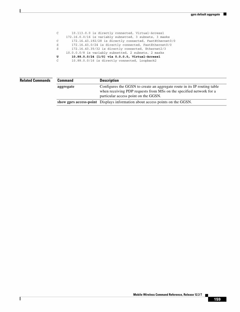
gprs default aggregate
C 10.113.0.0 is directly connected, Virtual-Access1 172.16.0.0/16 is variably subnetted, 3 subnets, 3 masksC 172.16.43.192/28 is directly connected, FastEthernet0/0S 172.16.43.0/24 is directly connected, FastEthernet0/0S 172.16.43.35/32 is directly connected, Ethernet2/3 10.0.0.0/8 is variably subnetted, 2 subnets, 2 masksU 10.88.0.0/24 [1/0] via 0.0.0.0, Virtual-Access1C 10.88.0.0/16 is directly connected, Loopback2
Related Commands Command Description
aggregate Configures the GGSN to create an aggregate route in its IP routing table when receiving PDP requests from MSs on the specified network for a particular access point on the GGSN.
show gprs access-point Displays information about access points on the GGSN.
159Mobile Wireless Command Reference, Release 12.3 T

gprs default charging-gateway
gprs default charging-gatewayTo specify the default charging gateway, use the gprs default charging gateway global configuration command. To remove the charging gateway, use the no form of this command.
gprs default charging-gateway {ip-address | name} [{ip-address | name}]
no gprs default charging-gateway {ip-address | name} [{ip-address | name}]
Syntax Description
Defaults No default charging gateway is assigned.
Command Modes Global configuration
Command History
Usage Guidelines Use the gprs default charging-gateway command to specify the IP address or host name of a default charging gateway that the GGSN uses to communicate charging information. If you specify two gateways, then the first gateway is the primary gateway, and the second gateway is the backup.
Examples The following example specifies two default charging gateway IP addresses:
gprs default charging-gateway 10.100.0.3 10.100.0.2
Related Commands
ip-address IP address of a default gateway.
name Host name for a default gateway.
Release Modification
12.1(1)GA This command was introduced.
12.1(5)T This command was integrated in Cisco IOS Release 12.1(5)T.
12.2(4)MX This command was incorporated in Cisco IOS Release 12.2(4)MX.
12.2(8)YD This command was incorporated in Cisco IOS Release 12.2(8)YD.
12.2(8)B This command was incorporated in Cisco IOS Release 12.2(8)B.
12.3(4)T This command was incorporated in Cisco IOS Release 12.3(4)T.
12.3(8)T This command was incorporated in Cisco IOS Release 12.3(8)T.
160Mobile Wireless Command Reference, Release 12.3 T

gprs default charging-gateway
Command Description
gprs charging container volume-threshold
Specifies the maximum number of bytes that the GGSN maintains across all containers for a particular PDP context before closing and updating the CDR.
gprs charging flow-control private-echo
Implements an echo request with private extensions for maintaining flow control on packets transmitted to the charging gateway.
gprs charging packet-queue-size
Specifies the maximum number of unacknowledged charging data transfer requests that the GGSN maintains in its queue.
gprs charging server-switch-timer
Specifies a timeout value that determines when the GGSN attempts to find an alternate charging gateway after a destination charging gateway cannot be located or becomes unusable.
gprs charging tariff-time
Specifies a time of day when GPRS charging tariffs change.
gprs charging transfer interval
Specifies the number of seconds that the GGSN waits before it transfers charging data to the charging gateway.
show gprs charging parameters
Displays information about the current GPRS charging configuration.
161Mobile Wireless Command Reference, Release 12.3 T
gprs default dhcp-server
gprs default dhcp-serverTo specify a default Dynamic Host Configuration Protocol (DHCP) server from which the GGSN obtains IP address leases for mobile users, use the gprs default dhcp-server global configuration command. To remove the default DHCP server, use the no form of this command.
gprs default dhcp-server {ip-address | name} [{ip-address | name}]
no gprs default dhcp-server {ip-address | name} [{ip-address | name}]
Syntax Description
Defaults No default behavior or values.
Command Modes Global configuration
Command History
Usage Guidelines Use the gprs default dhcp-server command to specify a DHCP server from which the GGSN obtains IP address leases for mobile users across all access points. Use the optional second set of arguments to specify the name, or IP address, of a backup DHCP server to use if the primary DHCP server is unavailable. If you do not specify a backup DHCP server, then no backup DHCP server is available.
In addition to specifying a DHCP server for the GGSN, you must also specify the GGSN as a DHCP proxy client. You can configure the GGSN as a DHCP proxy client using either the gprs default ip-address-pool dhcp-proxy-client global configuration command, or the ip-address-pool dhcp-proxy-client access-point configuration command.
ip-address IP address of a DHCP server. The first IP address is the name of the primary DHCP server. The second (optional) ip-address argument specifies the IP address of a backup DHCP server.
name Host name of a DHCP server. The second (optional) name argument specifies the host name of a backup DHCP server.
Release Modification
12.1(1)GA This command was introduced.
12.1(5)T This command was integrated in Cisco IOS Release 12.1(5)T.
12.2(4)MX This command was incorporated in Cisco IOS Release 12.2(4)MX.
12.2(8)YD This command was incorporated in Cisco IOS Release 12.2(8)YD.
12.2(8)B This command was incorporated in Cisco IOS Release 12.2(8)B.
12.3(4)T This command was incorporated in Cisco IOS Release 12.3(4)T.
12.3(8)T This command was incorporated in Cisco IOS Release 12.3(8)T.
162Mobile Wireless Command Reference, Release 12.3 T

gprs default dhcp-server
You can override the DHCP server that is configured globally, and specify a different DHCP server for a particular access point using the dhcp-server access-point configuration command. If you do not specify a DHCP server for a specified access point, then the DHCP server specified with the gprs default dhcp-server command is used for that access point.
Note You cannot specify a DHCP server that is located within a private network using VRF with the gprs default dhcp-server global configuration command. To specify a DHCP server that is within a VRF address space, you must use the dhcp-server access-point configuration command.
Examples The following example specifies 10.101.100.3 as the GPRS default DHCP server for GPRS, using the gprs default dhcp-server command. Although this DHCP server is also configured globally on the router using the ip dhcp-server global configuration command, this is not required.
Because DHCP is the default dynamic addressing method specified by the gprs default ip-address-pool dhcp-proxy-client command, access-point 3 will use the DHCP server located at 10.101.100.3 for IP addressing support. Access-point 1 and access-point 2 override the default DHCP server using the dhcp-server access-point configuration command to specify alternative DHCP servers:
interface Loopback1ip address 10.30.30.30 255.255.255.255
!interface Loopback2ip address 10.27.27.27 255.255.255.255
!interface Loopback3ip address 10.25.25.25 255.255.255.255
!interface virtual-template 1ip address 10.15.10.1 255.255.255.0no ip directed-broadcastencapsulation gtpgprs access-point-list abc
!gprs access-point-list abcaccess-point 1access-point-name gprs.pdn1.comdhcp-server 10.102.100.3 dhcp-gateway-address 10.30.30.30exit
!access-point 2access-point-name gprs.pdn2.comdhcp-server 10.60.0.1 dhcp-gateway-address 10.27.27.27 exit
!access-point 3access-point-name www.pdn3.comaccess-mode non-transparentdhcp-gateway-address 10.25.25.25exit
!gprs default ip-address-pool dhcp-proxy-clientgprs default dhcp-server 10.101.100.3
163Mobile Wireless Command Reference, Release 12.3 T

gprs default dhcp-server
Related Commands Command Description
dhcp-server Specifies a primary (and backup) DHCP server to allocate IP addresses to MS users entering a particular PDN access point.
gprs default ip-address-pool
Specifies a dynamic address allocation method using IP address pools for the GGSN.
ip-address-pool Specifies a dynamic address allocation method using IP address pools for the current access point.
164Mobile Wireless Command Reference, Release 12.3 T

gprs default ip-address-pool
gprs default ip-address-poolTo specify a dynamic address allocation method using IP address pools for the GGSN, use the gprs default ip-address-pool global configuration command. To disable dynamic address allocation, use the no form of this command.
gprs default ip-address-pool {dhcp-proxy-client | disable | radius-client}
no gprs default ip-address-pool {dhcp-proxy-client | disable | radius-client}
Syntax Description
Defaults IP address pools are disabled.
Command Modes Global configuration
Command History
Usage Guidelines Use the gprs default ip-address-pool command to specify the method by which the GGSN obtains address leases for mobile stations across all access points.
If you specify dhcp-proxy-client for the GPRS default IP address pool, then you must specify a DHCP server for address allocation. To specify a DHCP server, use either the gprs default dhcp-server global configuration command, or the dhcp-server access-point configuration command.
If you specify radius-client as the method for IP address allocation, then you must configure RADIUS services at the GGSN. This involves configuring AAA server groups using the gprs default aaa-group or aaa-group commands, and configuring the radius-server host commands to specify the RADIUS servers that provide the address pool. You also need to configure AAA on the GGSN. For more information about configuring RADIUS on the GGSN, refer to the Usage Guidelines section for the aaa-group and gprs default aaa-group commands.
To disable the selected IP address allocation method, use the no form of this command or issue the command with the disable keyword (the default form of this command).
dhcp-proxy-client GGSN dynamically acquires IP addresses for an MS from a DHCP server.
disable Disables dynamic address allocation by the GGSN.
radius-client GGSN dynamically acquires IP addresses for an MS from a RADIUS server.
Release Modification
12.1(1)GA This command was introduced.
12.1(5)T This command was integrated in Cisco IOS Release 12.1(5)T.
12.2(4)MX This command was incorporated in Cisco IOS Release 12.2(4)MX.
12.2(8)YD This command was incorporated in Cisco IOS Release 12.2(8)YD.
12.2(8)B This command was incorporated in Cisco IOS Release 12.2(8)B.
12.3(4)T This command was incorporated in Cisco IOS Release 12.3(4)T.
12.3(8)T This command was incorporated in Cisco IOS Release 12.3(8)T.
165Mobile Wireless Command Reference, Release 12.3 T
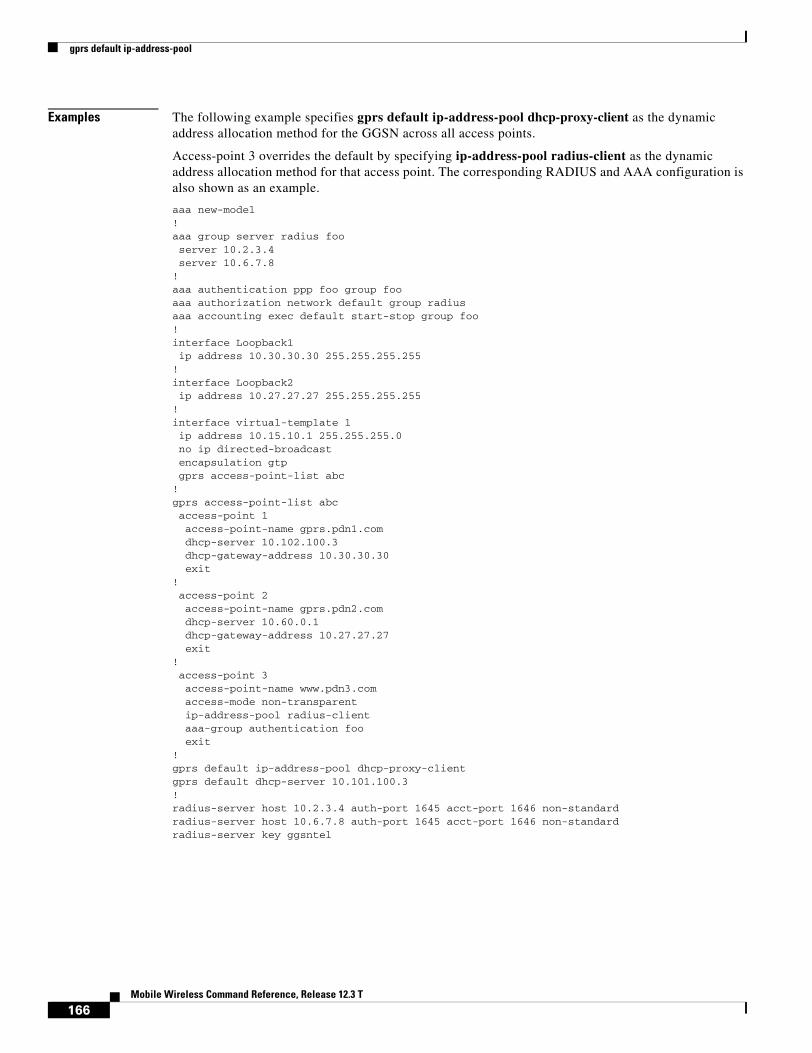
gprs default ip-address-pool
Examples The following example specifies gprs default ip-address-pool dhcp-proxy-client as the dynamic address allocation method for the GGSN across all access points.
Access-point 3 overrides the default by specifying ip-address-pool radius-client as the dynamic address allocation method for that access point. The corresponding RADIUS and AAA configuration is also shown as an example.
aaa new-model!aaa group server radius fooserver 10.2.3.4server 10.6.7.8
!aaa authentication ppp foo group fooaaa authorization network default group radius aaa accounting exec default start-stop group foo!interface Loopback1ip address 10.30.30.30 255.255.255.255
!interface Loopback2ip address 10.27.27.27 255.255.255.255
!interface virtual-template 1ip address 10.15.10.1 255.255.255.0no ip directed-broadcastencapsulation gtpgprs access-point-list abc
!gprs access-point-list abcaccess-point 1access-point-name gprs.pdn1.comdhcp-server 10.102.100.3 dhcp-gateway-address 10.30.30.30exit
!access-point 2access-point-name gprs.pdn2.comdhcp-server 10.60.0.1 dhcp-gateway-address 10.27.27.27 exit
!access-point 3access-point-name www.pdn3.comaccess-mode non-transparentip-address-pool radius-clientaaa-group authentication fooexit
!gprs default ip-address-pool dhcp-proxy-clientgprs default dhcp-server 10.101.100.3!radius-server host 10.2.3.4 auth-port 1645 acct-port 1646 non-standardradius-server host 10.6.7.8 auth-port 1645 acct-port 1646 non-standardradius-server key ggsntel
166Mobile Wireless Command Reference, Release 12.3 T

gprs default ip-address-pool
Related Commands Command Description
dhcp-server Specifies a primary (and backup) DHCP server to allocate IP addresses to MS users entering a particular PDN access point.
gprs default dhcp-server
Specifies a default DHCP server from which the GGSN obtains IP address leases for mobile users.
ip-address-pool Specifies a dynamic address allocation method using IP address pools for the current access point.
aaa-group Specifies a AAA server group and assigns the type of AAA services to be supported by the server group for a particular access point on the GGSN.
gprs default aaa-group Specifies a default AAA server group and assigns the type of AAA services to be supported by the server group for all access points on the GGSN.
167Mobile Wireless Command Reference, Release 12.3 T
gprs default map-converting-gsn
gprs default map-converting-gsnTo specify the IP address or host name of the primary (and backup) GSN to communicate with the HLR in sending and receiving MAP messages, use the gprs default map-converting-gsn global configuration command. To remove the GSN configuration, use the no form of this command.
gprs default map-converting-gsn {ip-address | hostname} [ip-address | hostname]
no gprs default map-converting-gsn {ip-address | hostname} [ip-address | hostname]
Syntax Description
Defaults No default behavior or values.
Command Modes Global configuration
Command History
Usage Guidelines Use the gprs default map-converting-gsn command to identify an GSN that can convert GTP messages to and from Mobile Application Protocol (MAP) messages. This GTP-to-MAP and MAP-to-GTP conversion allows the GSN to communicate with an HLR.
The GGSN must be able to send MAP messages to an HLR to support network-initiated PDP requests. Network-initiated PDP requests are one example of an application that requires this MAP conversion function.
The GGSN supports a maximum of two protocol-converting GSNs. Therefore, you can specify both a primary and backup GSN using a single gprs default map-converting-gsn command. However, you cannot configure more than one instance of the gprs default map-converting-gsn command.
The GGSN uses the backup GSN when the GGSN reaches the maximum signaling threshold (N3 GTP signaling requests x T3).
In addition to configuring the gprs default map-converting-gsn command, you must configure the following other commands to support network-initiated PDP requests on the GGSN:
ip-address IP address of the GSN handling MAP messages with the HLR. The first ip-address argument specifies the IP address of the primary GSN. The second (optional) ip-address argument specifies the IP address of a backup GSN.
hostname Host name of the GSN handling MAP messages with the HLR. The second (optional) name argument specifies the host name of a backup GSN.
Release Modification
12.2(4)MX This command was introduced.
12.2(8)YD This command was incorporated in Cisco IOS Release 12.2(8)YD.
12.2(8)B This command was incorporated in Cisco IOS Release 12.2(8)B.
12.3(4)T This command was incorporated in Cisco IOS Release 12.3(4)T.
12.3(8)T This command was incorporated in Cisco IOS Release 12.3(8)T.
168Mobile Wireless Command Reference, Release 12.3 T

gprs default map-converting-gsn
• gprs ni-pdp ip-imsi single
• network-request-activation
Examples The following example configures the GSN, located at IP address 172.16.10.10, to convert MAP messages between the HLR and the GGSN:
gprs default map-converting-gsn 172.16.10.10
Related Commands Command Description
gprs ni-pdp ip-imsi single Specifies a static IP address to IMSI mapping for a single MS for network-initiated PDP requests from a particular APN.
network-request-activation Enables an access point to support network-initiated PDP requests to a MS.
169Mobile Wireless Command Reference, Release 12.3 T

gprs delay-qos map tos
gprs delay-qos map tosTo specify a QoS mapping from the delay QoS classes to an IP type of service (ToS) precedence value, use the gprs delay-qos map tos class global configuration command. To return to the default values, use the no form of this command.
gprs delay-qos map tos class1 tos-value [class2 tos-value [class3 tos-value [class-best-effort tos-value]]]
no gprs delay-qos map tos class1 tos-value [class2 tos-value [class3 tos-value [class-best-effort tos-value]]]
Syntax Description
Defaults The default value for the class1 ToS category is 3.
The default value for the class2 ToS category is 2.
The default value for the class3 ToS category is 1.
The default value for the class-best-effort ToS category is 0.
Command Modes Global configuration
Command History
Usage Guidelines Use the gprs delay-qos map tos command to specify a mapping between various QoS categories and the ToS precedence bits in the IP header for packets transmitted over the Gn interface (GTP tunnels).
Note You must enable delay QoS mapping by configuring the gprs qos map delay command before configuring the gprs delay-qos map tos command.
class1 tos-value ToS mapping for a delay1 class QoS. The tos-value can be a number from 0 to 4. The default is 3.
class2 tos-value ToS mapping for a delay2 class QoS. The tos-value can be a number from 0 to 4. The default is 2.
class3 tos-value ToS mapping for a delay3 class QoS. The tos-value can be a number from 0 to 4. The default is 1.
class-best-effort tos-value
ToS mapping for a delaybesteffort class QoS. The tos-value can be a number from 0 to 4. The default is 0.
Release Modification
12.2(4)MX This command was introduced.
12.2(8)YD This command was incorporated in Cisco IOS Release 12.2(8)YD.
12.2(8)B This command was incorporated in Cisco IOS Release 12.2(8)B.
12.3(4)T This command was incorporated in Cisco IOS Release 12.3(4)T.
12.3(8)T This command was incorporated in Cisco IOS Release 12.3(8)T.
170Mobile Wireless Command Reference, Release 12.3 T

gprs delay-qos map tos
The class2, class3 and class-best-effort keyword arguments are optional. However, if you specify a value for the class3 argument, you must specify a value for the class2 argument. And, if you specify a value for the class-best-effort argument, then you must specify a value for both the class2 and the class3 arguments.
Only ToS classes 0 through 5 will be used for GGSN signaling and user data. The GTP signaling message should have the highest precedence. ToS class 5 is the default ToS for GTP signaling. Use the gprs gtp map signalling tos command to specify an IP ToS mapping for GTP signaling packets.
The ToS precedence classes are defined as follows:
0 Routine
1 Priority
2 Immediate
3 Flash
4 Flash Override
5 Critical ECP
6 Internetwork Control
7 Network Control
Examples The following example specifies a QoS mapping from the delay QoS classes to a class1 ToS category of four, a class2 ToS category of three, a class3 ToS category of two, and a best-effort ToS category of one.
gprs delay-qos map tos class1 4 class2 3 class3 2 class-best-effort 1
Related Commands Command Description
gprs gtp map signalling tos
Specifies an IP ToS mapping for GPRS signaling packets.
gprs qos default-response requested
Configures the GGSN to set its default QoS values in the response message exactly as requested in the create PDP context request message.
gprs qos map delay Enables mapping of GPRS QoS categories to a delay QoS method that includes the delaybesteffort, delay1, delay2, and delay3 classes.
171Mobile Wireless Command Reference, Release 12.3 T
gprs dfp max-weight
gprs dfp max-weightTo specify the maximum weight sent to a DFP manager by a GGSN acting as a DFP agent, use the gprs dfp max-weight global configuration command. To return to the default value, use the no form of this command.
gprs dfp max-weight [max-weight-value]
no gprs dfp max-weight [max-weight-value]
Syntax Description
Defaults 8
Command Modes Global configuration
Command History
Usage Guidelines If you use DFP with GPRS load balancing, you must also specify a maximum number of PDP contexts for each GGSN, using the gprs maximum-pdp-context-allowed command. Do not accept the default value of 10000 PDP contexts. A value of 45000 is recommended. Significantly lower values can impact performance in a GPRS load-balancing environment.
Note For more information about configuring GPRS load balancing, see the IOS Server Load Balancing, 12.1(9)E documentation located at Cisco.com at the following URL:
http://www.cisco.com/univercd/cc/td/doc/product/software/ios121/121newft/121limit/121e/121e9/index.htm
Examples The following example sets the maximum weight sent by GGSN to 43:
gprs dfp max-weight 43
max-weight-value Specifies the maximum weight sent by the GGSN, acting as a DFP agent, to a DFP manager. The valid range is 1 to 100. The default value is 8.
Release Modification
12.1(9)E This command was introduced.
12.2(4)MX This command was incorporated in Cisco IOS Release 12.2(4)MX.
12.2(8)YD This command was incorporated in Cisco IOS Release 12.2(8)YD.
12.2(8)B This command was incorporated in Cisco IOS Release 12.2(8)B.
12.3(4)T This command was incorporated in Cisco IOS Release 12.3(4)T.
12.3(8)T This command was incorporated in Cisco IOS Release 12.3(8)T.
172Mobile Wireless Command Reference, Release 12.3 T

gprs dfp max-weight
Related Commands Command Description
agent Identifies a DFP agent to which IOS SLB can connect.
gprs maximum-pdp-context-allowed Specifies the maximum number of PDP contexts (mobile sessions) that can be activated on the GGSN.
ip dfp agent Identifies a DFP agent subsystem and enters DFP agent configuration mode.
ip slb dfp Configures DFP, supplies an optional password, and enters DFP configuration mode.
173Mobile Wireless Command Reference, Release 12.3 T

gprs dfp max-weight
174Mobile Wireless Command Reference, Release 12.3 T

gprs gtp echo-timer dynamic enable
gprs gtp echo-timer dynamic enableTo enable the dynamic echo timer on the GGSN, use the gprs gtp echo-timer dynamic enable global configuration command. To disable the dynamic echo timer, use the no form of this command.
gprs gtp echo-timer dynamic enable
no gprs gtp echo-timer dynamic enable
Syntax Description This command has no arguments or keywords.
Defaults Disabled
Command Modes Global configuration
Command History
Usage Guidelines For a GTP path to be active, the SGSN needs to be active. To determine that an SGSN is active, the GGSN and SGSN exchange echo messages. Although the GGSN supports different methods of echo message timing, the basic echo flow begins when the GGSN sends an echo request message to the SGSN. The SGSN sends a corresponding echo response message back to the GGSN.
If the GGSN does not receive a response after a certain number of retries (a configurable value), the GGSN assumes that the SGSN is not active. This indicates a GTP path failure, and the GGSN clears all PDP context requests associated with that path.
The GGSN supports two different methods of echo timing—the default echo timer and the dynamic echo timer.
The GGSN’s default echo timer can not be configured to accommodate network congestion and therefore the GTP path could be cleared prematurely. The dynamic echo timer feature enables the GGSN to better manage the GTP path during periods of network congestion. Use the gprs gtp echo-timer dynamic enable command to enable the GGSN to perform dynamic echo timing.
Default echo timer
The dynamic echo timer is based on the default echo timer in the GGSN. A description of the default echo timer follows as a means of comparison.
The default echo timer configuration uses the following commands:
Release Modification
12.2(4)MX This command was introduced.
12.2(8)YD This command was incorporated in Cisco IOS Release 12.2(8)YD.
12.2(8)B This command was incorporated in Cisco IOS Release 12.2(8)B.
12.3(4)T This command was incorporated in Cisco IOS Release 12.3(4)T.
12.3(8)T This command was incorporated in Cisco IOS Release 12.3(8)T.
175Mobile Wireless Command Reference, Release 12.3 T

gprs gtp echo-timer dynamic enable
• gprs gtp n3-requests—Specifies maximum number of times that the GGSN attempts to send a echo-request message. The default is 5 times.
• gprs gtp path-echo-interval—Specifies the number of seconds that the GGSN waits before sending an echo-request message to the SGSN. The default is 60 seconds.
• gprs gtp t3-response—Specifies the number of seconds that the GGSN waits before resending an echo-request message after the path echo interval has expired and the echo response from the SGSN has not been received. The default is 1 second.
If the GGSN receives the echo response within the path echo interval (as specified in the gprs gtp path-echo-interval command; default is 60 seconds), it sends another echo request message after 60 seconds (or whatever time was configured in the gprs gtp path-echo-interval command). This message flow continues as long as the GGSN receives an echo response message from the SGSN within the specified path echo interval.
If the GGSN fails to receive an echo response message from the SGSN within the path echo interval, it resends echo request messages until the N3-requests counter is reached (as specified by the gprs gtp n3-requests command; default is 5). Because the initial request message is included in the N3-requests counter, the total number of retries is N3-1. The T3 timer increases by a factor of two for each retry (the factor value is not configurable).
For example, if N3 is set to the default of 5, and T3 is set to the default of 1 second, the GGSN will resend 4 echo request messages (the initial request + 4 retries=5). The T3 time increments for each additional echo request, by a factor of 2 seconds. So, the GGSN resends a message in 2 seconds, 4 seconds, 8 seconds, and 16 seconds. If the GGSN fails to receive an echo response message from the SGSN within the time period of the N3-requests counter, it clears the GTP path and deletes all of the PDP contexts.
For the above example, the total elapsed time from when the first request message is sent, to when the GTP path is cleared, is: 60+2+4+8+16=90 seconds,
where 60 is the initial value of the path echo interval, and the remaining 4 time periods are the increments of the T3 timer for the subsequent retries.
Dynamic echo timer
The dynamic echo timer method is different from the default echo timer method on the GGSN because it uses a calculated round-trip timer (RTT), as well as a configurable factor or multiplier to be applied to the RTT statistic.
The dynamic echo timer configuration uses the following commands:
• gprs gtp echo-timer dynamic enable—Enables the dynamic echo timer on the GGSN.
• gprs gtp echo-timer dynamic minimum—Specifies the minimum time period (in seconds) for the dynamic echo timer. If the RTT is less than this value, the GGSN uses the value set in this command.
• gprs gtp echo-timer dynamic smooth-factor—Configures the multiplier that the dynamic echo timer uses when calculating the time to wait to send retries, when it has not received a response from the SGSN within the path echo interval.
• gprs gtp n3-requests—Specifies the maximum number of times that the GGSN attempts to send an echo-request message. The default is 5 times.
• gprs gtp path-echo-interval—Specifies the number of seconds within which the GGSN expects to receive an echo response from the SGSN. This is the period of time that the GGSN waits before sending another echo-request message. The default is 60 seconds.
176Mobile Wireless Command Reference, Release 12.3 T

gprs gtp echo-timer dynamic enable
The GGSN calculates the RTT statistic for use by the dynamic echo timer feature. The RTT is the amount of time between sending a particular echo request message and receiving the corresponding echo response message. RTT is calculated for the first echo response received; the GGSN records this statistic. Because the RTT value might be a very small number, there is a minimum time for the dynamic echo timer to use. This value is configured using the gprs gtp echo-timer dynamic minimum command.
If the GGSN fails to receive an echo response message from the SGSN within the path echo interval, it goes into retransmission, or path failure mode. During path failure mode, the GGSN uses a value referred to as the T-dynamic. The T-dynamic is the greater of either the dynamic minimum, or the RTT statistic multiplied by the smooth factor.
The T-dynamic essentially replaces the use of the gprs gtp t3-response command, which is used in the default echo timer method on the GGSN. The T-dynamic timer increases by a factor of two for each retry (again, this factor is not configurable), until the N3-requests counter is reached (N3-requests counter includes the initial request message).
For example, if the RTT is 6 seconds, N3 is set to 5, and the smooth factor is set to 3, the GGSN will resend 4 echo request messages in path failure mode. The T-dynamic value is 18 (RTT x smooth factor), so the GGSN sends a retry echo request message in 36 seconds, 72 seconds, 144 seconds, and 288 seconds. If the GGSN fails to receive an echo response message from the SGSN in this time period, it clears the GTP path and deletes all PDP contexts. The total elapsed time from when the first request message is sent to when the GTP path is cleared is: 60+36+72+144+288=600 seconds, where 60 is the initial value of the path echo interval, and the remaining 4 time periods are the increments of the T-dynamic for the subsequent retries.
Examples The following example turns on the dynamic echo timer, sets the minimum value to 5 seconds, and configures a smooth factor of 3:
gprs gtp echo-timer dynamic enablegprs gtp echo-timer dynamic minimum 5gprs gtp echo-timer dynamic smooth-factor 3
Related Commands Command Description
gprs gtp echo-timer dynamic minimum
Specifies the minimum time period used by the dynamic echo timer.
gprs gtp echo-timer dynamic smooth-factor
Configures the multiplier that the GGSN uses to calculate the time to wait to send retries of the dynamic echo timer.
gprs gtp n3-requests Specifies the maximum number of times that the GGSN attempts to send a signaling request.
gprs gtp path-echo-interval
Specifies the number of seconds that the GGSN waits before sending an echo-request message to the SGSN.
177Mobile Wireless Command Reference, Release 12.3 T
gprs gtp echo-timer dynamic minimum
gprs gtp echo-timer dynamic minimumTo specify the minimum time period used by the dynamic echo timer, use the gprs gtp echo-timer dynamic minimum global configuration command. To return to the default value, use the no form of this command.
gprs gtp echo-timer dynamic minimum number
no gprs gtp echo-timer dynamic minimum number
Syntax Description
Defaults 5 seconds
Command Modes Global configuration
Command History
Usage Guidelines Use this command to specify the minimum time period (in seconds) used by the dynamic echo timer, also referred to as the T-dynamic. If the GGSN’s current calculation of the round-trip timer (RTT) statistic, multiplied by the smooth factor, is less than the configured dynamic minimum value, then the GGSN uses the configured minimum as the T-dynamic.
The GGSN calculates the RTT statistic for use by the dynamic echo timer feature. The RTT is the amount of time between sending a particular echo request message and receiving the corresponding echo response message. RTT is calculated for the first echo response received; the GGSN records this statistic. Because the RTT value might be a very small number, there is a minimum time for the dynamic echo timer to use. This value is configured using the gprs gtp echo-timer dynamic minimum command.
If the GGSN fails to receive an echo response message from the SGSN within the path echo interval, it goes into retransmission, or path failure mode. During path failure mode, the GGSN uses a value referred to as the T-dynamic. The T-dynamic is the greater of either the dynamic minimum, or the RTT statistic multiplied by the smooth factor.
The T-dynamic essentially replaces the use of the gprs gtp t3-response command, which is used in the default echo timer method on the GGSN. The T-dynamic timer increases by a factor of two for each retry (again, this factor is not configurable), until the N3-requests counter is reached (N3-requests counter includes the initial request message).
number Minimum time period (between 1 and 60 seconds) of the dynamic echo timer. Value must be an integer. The default value is 5 seconds.
Release Modification
12.2(4)MX This command was introduced.
12.2(8)YD This command was incorporated in Cisco IOS Release 12.2(8)YD.
12.2(8)B This command was incorporated in Cisco IOS Release 12.2(8)B.
12.3(4)T This command was incorporated in Cisco IOS Release 12.3(4)T.
12.3(8)T This command was incorporated in Cisco IOS Release 12.3(8)T.
178Mobile Wireless Command Reference, Release 12.3 T

gprs gtp echo-timer dynamic minimum
Note For more information about the dynamic echo timer on the GGSN, refer to the Usage Guidelines section for the gprs gtp echo-timer dynamic enable command.
Examples The following example turns on the dynamic echo timer, sets the minimum value to 6 seconds, and configures a smooth factor of 2:
gprs gtp echo-timer dynamic enablegprs gtp echo-timer dynamic minimum 6gprs gtp echo-timer dynamic smooth-factor 2
Related Commands Command Description
gprs gtp echo-timer dynamic enable
Enables the dynamic echo timer on the GGSN.
gprs gtp echo-timer dynamic smooth-factor
Configures the multiplier that the GGSN uses to calculate the time to wait to send retries of the dynamic echo timer.
gprs gtp n3-requests Specifies the maximum number of times that the GGSN attempts to send a signaling request.
gprs gtp path-echo-interval
Specifies the number of seconds that the GGSN waits before sending an echo-request message to the SGSN.
179Mobile Wireless Command Reference, Release 12.3 T

gprs gtp echo-timer dynamic smooth-factor
gprs gtp echo-timer dynamic smooth-factorTo configure the multiplier that the GGSN uses to calculate the time to wait to send retries of the dynamic echo timer, use the gprs gtp echo-timer dynamic smooth-factor global configuration command. To return to the default value, use the no form of this command.
gprs gtp echo-timer dynamic smooth-factor number
no gprs gtp echo-timer dynamic smooth-factor number
Syntax Description
Defaults 2
Command Modes Global configuration
Command History
Usage Guidelines The dynamic echo timer uses the smooth factor to calculate what is known as the T-dynamic. The T-dynamic is calculated by multiplying the RTT (or the value configured in the gprs gtp echo-timer dynamic minimum, whichever is greater) times the smooth-factor.
Note Refer to the Usage Guidelines section for the gprs gtp echo-timer dynamic enable command for a detailed explanation of how the dynamic echo timer works.
Examples The following example turns on the dynamic echo timer, sets the minimum value to 1 second, and configures a smooth factor of 2:
gprs gtp echo-timer dynamic enablegprs gtp echo-timer dynamic minimum 1gprs gtp echo-timer dynamic smooth-factor 2
number Integer (between 1 and 100) used by the GGSN as a multiplier for the RTT statistic, to calculate the T-dynamic. The default is 2.
Release Modification
12.2(4)MX This command was introduced.
12.2(8)YD This command was incorporated in Cisco IOS Release 12.2(8)YD.
12.2(8)B This command was incorporated in Cisco IOS Release 12.2(8)B.
12.3(4)T This command was incorporated in Cisco IOS Release 12.3(4)T.
12.3(8)T This command was incorporated in Cisco IOS Release 12.3(8)T.
180Mobile Wireless Command Reference, Release 12.3 T
gprs gtp echo-timer dynamic smooth-factor
Related Commands Command Description
gprs gtp echo-timer dynamic enable
Enables the dynamic echo timer on the GGSN.
gprs gtp echo-timer dynamic minimum
Specifies the minimum time period used by the dynamic echo timer.
gprs gtp n3-requests Specifies the maximum number of times that the GGSN attempts to send a signaling request.
gprs gtp path-echo-interval
Specifies the number of seconds that the GGSN waits before sending an echo-request message to the SGSN.
gprs gtp t3-response Specifies the initial time that the GGSN waits before resending a signaling request message when a response to a request has not been received
181Mobile Wireless Command Reference, Release 12.3 T

gprs gtp error-indication throttle
gprs gtp error-indication throttleTo specify the maximum number of error indication messages that the GGSN sends out in one second, use the gprs gtp error-indication throttle command. To disable the GGSN from sending error indication messages, use the no form of this command.
gprs gtp error-indication throttle window-size size
no gprs gtp error-indication throttle
Syntax Description
Defaults Disabled
Command Modes Global configuration
Command History
Usage Guidelines Use the gprs gtp error-indication throttle command to specify the maximum number of error indication messages that are sent by the GGSN in one second. This provides a way to implement flow control for transmission of GTP error messages. The GGSN maintains a counter that decrements each time that an error indication message is sent. The GGSN resets this counter to the configured throttle value after one second.
If you do not issue the command, error indication throttling is not enabled. To restore the default value (error indication throttling is disabled) use the no form of this command.
Examples The following example shows a throttle value of 150:
gprs gtp error-indication throttle window-size 150
size Integer (between 0 and 256) that specifies the maximum number of error indication messages that the GGSN sends in one second.
Release Modification
12.1(1)GA This command was introduced.
12.1(5)T This command was integrated in Cisco IOS Release 12.1(5)T.
12.2(4)MX This command was incorporated in Cisco IOS Release 12.2(4)MX.
12.2(8)YD This command was incorporated in Cisco IOS Release 12.2(8)YD.
12.2(8)B This command was incorporated in Cisco IOS Release 12.2(8)B.
12.3(4)T This command was incorporated in Cisco IOS Release 12.3(4)T.
12.3(8)T This command was incorporated in Cisco IOS Release 12.3(8)T.
182Mobile Wireless Command Reference, Release 12.3 T

gprs gtp ip udp ignore checksum
gprs gtp ip udp ignore checksumTo disable verification of the user datagram protocol (UDP) checksum to support CEF switching on the GGSN, use the gprs gtp ip udp ignore checksum global configuration command. To enable UDP checksum verification on the GGSN, use the no form of this command.
gprs gtp ip udp ignore checksum
no gprs gtp ip udp ignore checksum
Syntax Description This command has no arguments or keywords.
Defaults UDP checksum verification is enabled on the GGSN.
Command Modes Global configuration
Command History
Usage Guidelines UDP checksum verification can prohibit operation of CEF switching processing on the GGSN if the checksum should have a non-zero result. Therefore, if you want to enable CEF switching on the GGSN, you should configure the gprs gtp ip udp ignore checksum command.
If UDP checksum verification remains enabled on the GGSN and a non-zero result occurs, the GTP T-PDUs will be process switched, even if you have configured the GGSN for CEF switching.
The gprs gtp ip udp ignore checksum command does not apply if you are only using process switching on the GGSN.
For more information about switching processes on the router, refer to the Cisco IOS Switching Services Configuration Guide.
Examples The following example disables UDP checksum verification on the GGSN:
gprs gtp ip udp ignore checksum
Related Commands
Release Modification
12.2(4)MX This command was introduced.
12.2(8)YD This command was incorporated in Cisco IOS Release 12.2(8)YD.
12.2(8)B This command was incorporated in Cisco IOS Release 12.2(8)B.
12.3(4)T This command was incorporated in Cisco IOS Release 12.3(4)T.
12.3(8)T This command was incorporated in Cisco IOS Release 12.3(8)T.
Command Description
ip cef Enables CEF on the route processor card.
183Mobile Wireless Command Reference, Release 12.3 T

gprs gtp map signalling tos
gprs gtp map signalling tosTo specify an IP ToS mapping for GPRS tunneling protocol (GTP) signaling packets, use the gprs gtp map signalling tos global configuration command. To return to the default value, use the no form of this command.
gprs gtp map signalling tos tos-value
no gprs gtp map signalling tos tos-value
Syntax Description
Defaults ToS value 5
Command Modes Global configuration
Command History
Usage Guidelines Use the gprs gtp map signalling tos command to specify the IP ToS mapping for GTP signaling packets transmitted by the GGSN. The higher the value, the higher the class of service provided to the packets.
Examples The following example specifies a IP ToS mapping value of 3:
gprs gtp map signalling tos 3
Related Commands
tos-value Value between 0 and 7 that specifies the IP ToS mapping. The default value is 5.
Release Modification
12.1(1)GA This command was introduced.
12.1(5)T This command was integrated in Cisco IOS Release 12.1(5)T.
12.2(4)MX This command was incorporated in Cisco IOS Release 12.2(4)MX.
12.2(8)YD This command was incorporated in Cisco IOS Release 12.2(8)YD.
12.2(8)B This command was incorporated in Cisco IOS Release 12.2(8)B.
12.3(4)T This command was incorporated in Cisco IOS Release 12.3(4)T.
12.3(8)T This command was incorporated in Cisco IOS Release 12.3(8)T.
Command Description
gprs canonical-qos map tos
Specifies a QoS mapping from the canonical QoS classes to an IP ToS category.
gprs charging container volume-threshold
Specifies the maximum number of bytes that the GGSN maintains in a user's charging container before closing the charging container and updating the CDR.
gprs charging map data tos
Specifies an IP ToS mapping for GPRS charging data packets.
184Mobile Wireless Command Reference, Release 12.3 T

gprs gtp map signalling tos
gprs charging packet-queue-size
Specifies the maximum number of unacknowledged charging data transfer requests that the GGSN maintains in its queue.
gprs charging transfer interval
Specifies the number of seconds that the GGSN waits before it transfers charging data to the charging gateway.
Command Description
185Mobile Wireless Command Reference, Release 12.3 T

gprs gtp n3-buffer-size
gprs gtp n3-buffer-sizeTo specify the size of the receive buffer that the GGSN uses to receive GTP signaling messages and packets sent through the tunneling protocol, use the gprs gtp n3-buffer-size global configuration command. To return to the default value, use the no form of this command.
gprs gtp n3-buffer-size bytes
no gprs gtp n3-buffer-size
Syntax Description
Defaults 8192 bytes
Command Modes Global configuration
Command History
Usage Guidelines Use the gprs gtp n3-buffer-size command to specify the size of the GTP N3 buffer on the GGSN. The N3 buffer is a receive buffer that the GGSN uses to receive GTP signaling messages and packets sent through the tunneling protocol. The recommended value for the N3 buffer size is 8192 (the default size).
Examples The following example specifies a buffer size of 2084 bytes:
gprs gtp n3-buffer-size 2048
bytes Number of bytes (between 2048 and 65535) that specifies the size of the N3 buffer. The default is 8192 bytes.
Release Modification
12.1(1)GA This command was introduced.
12.1(5)T This command was integrated in Cisco IOS Release 12.1(5)T.
12.2(4)MX This command was incorporated in Cisco IOS Release 12.2(4)MX.
12.2(8)YD This command was incorporated in Cisco IOS Release 12.2(8)YD.
12.2(8)B This command was incorporated in Cisco IOS Release 12.2(8)B.
12.3(4)T This command was incorporated in Cisco IOS Release 12.3(4)T.
12.3(8)T This command was incorporated in Cisco IOS Release 12.3(8)T.
186Mobile Wireless Command Reference, Release 12.3 T

gprs gtp n3-requests
gprs gtp n3-requestsTo specify the maximum number of times that the GGSN attempts to send a signaling request to an SGSN, use the gprs gtp n3-requests global configuration command. To return to the default value, use the no form of this command.
gprs gtp n3-requests requests
no gprs gtp n3-requests requests
Syntax Description
Defaults 5 requests
Command Modes Global configuration
Command History
Usage Guidelines The value of the gprs gtp n3-requests command is used for all signaling requests on the GGSN.
The GGSN supports two different methods of echo timing—the default echo timer and the dynamic echo timer. The gprs gtp n3-requests command is used by the GGSN to perform either type of echo processing.
Examples The following example shows the GGSN attempting to send a signaling request 3 times:gprs gtp n3-requests 3
Related Commands
requests A number between 1 and 65535 that specifies the number of times a request is attempted. The default is 5 requests.
Release Modification
12.1(1)GA This command was introduced.
12.1(5)T This command was integrated in Cisco IOS Release 12.1(5)T.
12.2(4)MX This command was incorporated in Cisco IOS Release 12.2(4)MX.
12.2(8)YD This command was incorporated in Cisco IOS Release 12.2(8)YD.
12.2(8)B This command was incorporated in Cisco IOS Release 12.2(8)B.
12.3(4)T This command was incorporated in Cisco IOS Release 12.3(4)T.
12.3(8)T This command was incorporated in Cisco IOS Release 12.3(8)T.
Command Description
gprs gtp echo-timer dynamic enable
Enables the dynamic echo timer on the GGSN.
gprs gtp n3-buffer-size Specifies the size of the receive buffer that the GGSN uses to receive GTP signaling messages and packets sent through the tunneling protocol.
187Mobile Wireless Command Reference, Release 12.3 T

gprs gtp n3-requests
gprs gtp path-echo-interval
Specifies the number of seconds that the GGSN waits before sending an echo-request message to the SGSN.
gprs gtp t3-response Specifies the initial time that the GGSN waits before resending a signaling request message when a response to a request has not been received.
Command Description
188Mobile Wireless Command Reference, Release 12.3 T

gprs gtp path-echo-interval
gprs gtp path-echo-intervalTo specify the number of seconds that the GGSN waits before sending an echo-request message to the SGSN, use the gprs gtp path-echo-interval global configuration command. To return to the default value, use the no form of this command.
gprs gtp path-echo-interval interval
no gprs gtp path-echo-interval interval
Syntax Description
Defaults 60 seconds
Command Modes Global configuration mode
Command History
Usage Guidelines The GGSN supports two different methods of echo timing—the default echo timer and the dynamic echo timer. The gprs gtp path-echo-interval command is used on the GGSN to perform either type of echo processing.
Use the gprs gtp path-echo-interval command to specify the interval that the GGSN waits before sending an echo-request message to the SGSN to check for GTP path failure.
Note A value of 0 seconds disables echo requests on the GGSN.
Examples The following example shows the GGSN waiting 90 seconds before sending an echo-request message:
gprs gtp path echo-interval 90
interval Number of seconds that the GGSN waits before sending an echo-request message. Specify a value between 60 and 65535 seconds. The value 0 disables the echo-request feature. The default is 60 seconds.
Release Modification
12.1(1)GA This command was introduced.
12.1(5)T This command was integrated in Cisco IOS Release 12.1(5)T.
12.2(4)MX This command was incorporated in Cisco IOS Release 12.2(4)MX.
12.2(8)YD This command was incorporated in Cisco IOS Release 12.2(8)YD.
12.2(8)B This command was incorporated in Cisco IOS Release 12.2(8)B.
12.3(4)T This command was incorporated in Cisco IOS Release 12.3(4)T.
12.3(8)T This command was incorporated in Cisco IOS Release 12.3(8)T.
189Mobile Wireless Command Reference, Release 12.3 T

gprs gtp path-echo-interval
Related Commands Command Description
gprs gtp echo-timer dynamic enable
Enables the dynamic echo timer on the GGSN.
gprs gtp n3-requests Specifies the maximum number of times that the GGSN attempts to send a signaling request to an SGSN.
gprs gtp t3-response Specifies the initial time that the GGSN waits before resending a signaling request message when a response to a request has not been received.
190Mobile Wireless Command Reference, Release 12.3 T

gprs gtp ppp vtemplate
gprs gtp ppp vtemplateTo associate the virtual template interface that defines the PPP characteristics with support for the PPP PDP type over GTP on the GGSN, use the gprs gtp ppp vtemplate global configuration command. To remove specification of the PPP virtual template interface for GTP on the GGSN, use the no form of this command.
gprs gtp ppp vtemplate number
no gprs gtp ppp vtemplate number
Syntax Description
Defaults No default behavior or values.
Command Modes Global configuration
Command History
Usage Guidelines Before you configure the gprs gtp ppp vtemplate command, you must configure the virtual template interface with the necessary PPP characteristics. The number that you configure for the virtual template interface that defines the PPP characteristics, must correspond to the number that you specify in the gprs gtp ppp vtemplate command.
Examples The following example configures two virtual template interfaces on the GGSN, one for GTP encapsulation and one for PPP, and specifies the PPP virtual template interface for GTP on the GGSN.
Note The virtual template interface for PPP is a different virtual template interface than the GPRS virtual template interface for GTP encapsulation.
The first section of commands configures the GPRS virtual template interface for GTP:
interface Virtual-Template 1ip address 10.1.1.1 255.0.0.0
number Integer identifier of the virtual template interface over which the PPP characteristics are defined on the GGSN. This number must match the number configured in the corresponding interface virtual-template command.
Release Modification
12.2(4)MX This command was introduced.
12.2(8)YD This command was incorporated in Cisco IOS Release 12.2(8)YD.
12.2(8)B This command was incorporated in Cisco IOS Release 12.2(8)B.
12.3(4)T This command was incorporated in Cisco IOS Release 12.3(4)T.
12.3(8)T This command was incorporated in Cisco IOS Release 12.3(8)T.
191Mobile Wireless Command Reference, Release 12.3 T
gprs gtp ppp vtemplate
no ip directed-broadcastencapsulation gtpno ip route-cachegprs access-point-list gprs
The following example configures a virtual template interface for PPP and associates the virtual template for support of the PPP PDP type over GTP on the GGSN:
interface Virtual-Template 2ip unnumbered FastEthernet 1/0no ip directed-broadcastno peer default ip addressppp authentication chapppp timeout retry 30
gprs gtp ppp vtemplate 2
Related Commands Command Description
interface virtual-template Creates a virtual template interface that can be configured and applied dynamically in creating virtual access interfaces.
192Mobile Wireless Command Reference, Release 12.3 T

gprs gtp ppp-regeneration vtemplate
gprs gtp ppp-regeneration vtemplateTo associate the virtual template interface that is configured for PPP encapsulation with support for regenerated PPP sessions on the GGSN, use the gprs gtp ppp-regeneration vtemplate global configuration command. To remove specification of the PPP virtual template interface for regenerated PPP sessions on the GGSN, use the no form of this command.
gprs gtp ppp-regeneration vtemplate number
no gprs gtp ppp-regeneration vtemplate number
Syntax Description
Defaults No default behavior or values.
Command Modes Global configuration
Command History
Usage Guidelines Before you configure the gprs gtp ppp-regeneration vtemplate command, you must configure the virtual template interface for PPP encapsulation using the encapsulation ppp command. In addition, you must also configure the ip address negotiated command and the no peer neighbor-route command at the virtual template interface for PPP encapsulation.
The number that you configure for the virtual template interface to support PPP encapsulation, must correspond to the number that you specify in the gprs gtp ppp-regeneration vtemplate command.
Examples The following example configures two virtual template interfaces on the GGSN, one for GTP encapsulation for communication between the GGSN and the SGSN, and one for PPP regeneration. The virtual template interface for PPP regeneration supports the creation of PPP sessions from the GGSN over Layer 2 Tunneling Protocol (L2TP) tunnels to an L2TP network server (LNS).
Note The virtual template interface for PPP regeneration is a different virtual template interface than the GPRS virtual template interface for PPP PDP type support and for GTP encapsulation.
number Integer identifier of the virtual template interface which defines PPP encapsulation on the GGSN. This number must match the number configured in the corresponding interface virtual-template command.
Release Modification
12.2(4)MX This command was introduced.
12.2(8)YD This command was incorporated in Cisco IOS Release 12.2(8)YD.
12.2(8)B This command was incorporated in Cisco IOS Release 12.2(8)B.
12.3(4)T This command was incorporated in Cisco IOS Release 12.3(4)T.
12.3(8)T This command was incorporated in Cisco IOS Release 12.3(8)T.
193Mobile Wireless Command Reference, Release 12.3 T

gprs gtp ppp-regeneration vtemplate
The first section of commands configures the GPRS virtual template interface for GTP:
interface Virtual-Template 1ip address 10.1.1.1 255.0.0.0no ip directed-broadcastencapsulation gtpno ip route-cachegprs access-point-list gprs
The following example configures a virtual template interface for PPP regeneration:
interface Virtual-Template 11ip address negotiatedno peer neighbor-routeencapsulation ppp
The following example specifies virtual template interface 11 for PPP regeneration on the GGSN:
gprs gtp ppp-regeneration vtemplate 11
Related Commands Command Description
interface virtual-template Creates a virtual template interface that can be configured and applied dynamically in creating virtual access interfaces.
194Mobile Wireless Command Reference, Release 12.3 T

gprs gtp response-message pco ipcp nack
gprs gtp response-message pco ipcp nackTo configure the GGSN to return an IPCP Conf-Nack (Code 03) in the GTP protocol configuration option (PCO) information element (IE) of a create PDP context response when returning IP Control Protocol (IPCP) options for which the granted values (non-zero) differ from those requested (IPCP Conf-Reject [Code 04] for those options for which the returned address values are zero), use the gprs gtp response-message pco ipcp nack global configuration command. To return to the default, use the no form of the command.
gprs gtp response-message pco ipcp nack
no gprs gtp response-message pco ipcp nack
Syntax Description This command has no arguments or keywords.
Defaults The GGSN sends an IPCP Conf-Ack (Code 2) in the PCO IE of the create PDP context response for the IPCP options for all the requested IPCP address options supported by the GGSN. The values being returned might be the same as or differ from those requested, or be zero.
For unsupported options, an IPCP Conf-Reject is returned.
Command Modes Global configuration
Command History
Usage Guidelines Use the gprs gtp response-message pco ipcp nack command to configure the GGSN to return an IPCP Conf-Nack in the PCO IE of a create PDP context response when returning IPCP options for which the granted values differ from those requested.
When the gprs gtp response-message pco ipcp nack command is configured, and the PCO IE of the create PDP context request contains IPCP options, the PCO IE in the create PDP response includes the following, depending on the whether options are supported by (and values are acceptible to) the GGSN:
• IPCP Conf-Ack—One or (zero) IPCP Conf-Ack for the IPCP options for which the requested values are acceptible by the GGSN.
• IPCP Conf-Nack—One or (zero) IPCP Conf-Nack containing the IPCP options for which the granted values differ from those requested.
• IPCP Conf-Reject—One (or zero) IPCP Conf-Reject containing the requested options which are not supported by the GGSN, or, if supported, for which no values can be granted.
Release Modification
12.3(2)XB1 This command was introduced.
12.3(8)T This command was incorporated in Cisco IOS Release 12.3(8)T.
195Mobile Wireless Command Reference, Release 12.3 T
gprs gtp response-message wait-accounting
gprs gtp response-message wait-accountingTo configure the GGSN to wait for a RADIUS accounting response before sending a create PDP context response to the SGSN, for create PDP context requests received across all access points, use the gprs gtp response-message wait-accounting global configuration command. To configure the GGSN to send a create PDP context response to the SGSN after sending a RADIUS start accounting message to the RADIUS server (without waiting for a response from the RADIUS accounting server), use the no form of this command.
gprs gtp response-message wait-accounting
no gprs gtp response-message wait-accounting
Syntax Description This command has no arguments or keywords.
Defaults The GGSN sends a create PDP context response to the SGSN after sending a RADIUS start accounting message to the RADIUS accounting server. The GGSN does not wait for a RADIUS accounting response from the RADIUS accounting server.
Command Modes Global configuration
Command History
Usage Guidelines Use the gprs gtp response-message wait-accounting command to configure the GGSN to wait for a RADIUS accounting response from the RADIUS accounting server, before sending a create PDP context response to the SGSN, for create PDP context requests received across all access points.
If the GGSN does not receive a response from the RADIUS accounting server when you have configured the gprs gtp response-message wait-accounting command, then the GGSN rejects the PDP context request.
The GGSN supports configuration of RADIUS response message waiting at both the global and access-point configuration levels. You can minimize your configuration by specifying the configuration that you want to support across most APNs, at the global configuration level. Then, at the access-point configuration level, you can selectively modify the behavior that you want to support at a particular APN. Therefore, at the APN configuration level, you can override the global configuration of RADIUS response message waiting.
Release Modification
12.2(4)MX This command was introduced.
12.2(8)YD This command was incorporated in Cisco IOS Release 12.2(8)YD.
12.2(8)B This command was incorporated in Cisco IOS Release 12.2(8)B.
12.3(4)T This command was incorporated in Cisco IOS Release 12.3(4)T.
12.3(8)T This command was incorporated in Cisco IOS Release 12.3(8)T.
196Mobile Wireless Command Reference, Release 12.3 T

gprs gtp response-message wait-accounting
To configure the GGSN to wait for a RADIUS accounting response as the default behavior for all APNs, use the gprs gtp response-message wait-accounting global configuration command. To disable this behavior for a particular APN, use the no response-message wait-accounting access-point configuration command.
To verify whether RADIUS response message waiting is enabled or disabled at an APN, you can use the show gprs access-point command and observe the value reported in the wait_accounting output field.
Examples The following example globally configures the GGSN to wait for a RADIUS accounting response from the RADIUS accounting server before sending an activate PDP context response to the SGSN, for PDP context requests received across all access points except access-point 1. RADIUS response message waiting has been overridden at access-point 1 using the no gtp response-message wait-accounting command:
Note This example shows only a partial configuration of the GGSN, to highlight those commands related to implementing RADIUS response message waiting. Additional configuration statements are required to complete a full configuration of the GGSN.
aaa new-model!aaa group server radius fooserver 10.2.3.4server 10.6.7.8
!aaa authentication ppp foo group fooaaa authorization network default group radius aaa accounting exec default start-stop group foo!gprs access-point-list gprsaccess-point 1access-mode non-transparentaccess-point-name www.pdn1.comaaa-group authentication foono gtp response-message wait-accountingexit
access-point 2access-mode non-transparentaccess-point-name www.pdn2.comaaa-group authentication foo
!gprs gtp response-message wait-accounting!radius-server host 10.2.3.4 auth-port 1645 acct-port 1646 non-standardradius-server host 10.6.7.8 auth-port 1645 acct-port 1646 non-standardradius-server key ggsntel
Related Commands Command Description
gtp response-message wait-accounting Configures the GGSN to wait for a RADIUS accounting response before sending a create PDP context response to the SGSN, for create PDP context requests received at a particular APN.
show gprs access-point Displays information about access points on the GGSN.
197Mobile Wireless Command Reference, Release 12.3 T

gprs gtp t3-response
gprs gtp t3-responseTo specify the initial time that the GGSN waits before resending a signaling request message when a response to a request has not been received, use the gprs gtp t3-response global configuration command. To return to the default value, use the no form of this command.
gprs gtp t3-response response-interval
no gprs gtp t3-response response-interval
Syntax Description
Defaults 1 second
Command Modes Global configuration
Command History
Usage Guidelines The gprs gtp t3-response command is used by the GGSN to process delete PDP context requests and to perform the default method of echo timing.
For delete PDP context requests, the gprs gtp t3-response command is used by the GGSN to specify how long the GGSN waits before sending a retry of the delete PDP context request when a response is not received from the SGSN, until the gprs gtp n3-requests limit is reached.
The GGSN supports two echo timer implementations—the default echo timer and the dynamic echo timer. The gprs gtp t3-response command also is used on the GGSN to perform the default type of echo processing, when the dynamic echo timer is not enabled.
If the GGSN receives the echo response within the path echo interval (as specified in the gprs gtp path-echo-interval command; default is 60 seconds), it sends another echo request message after 60 seconds (or whatever time was configured in the gprs gtp path-echo-interval command). This message flow continues as long as the GGSN receives an echo response message from the SGSN within the specified path echo interval.
response-interval A value between 1 and 65535 that specifies the length of the T3 response interval, in seconds. The default is 1 second.
Release Modification
12.1(1)GA This command was introduced.
12.1(5)T This command was integrated in Cisco IOS Release 12.1(5)T.
12.2(4)MX This command was incorporated in Cisco IOS Release 12.2(4)MX.
12.2(8)YD This command was incorporated in Cisco IOS Release 12.2(8)YD.
12.2(8)B This command was incorporated in Cisco IOS Release 12.2(8)B.
12.3(4)T This command was incorporated in Cisco IOS Release 12.3(4)T.
12.3(8)T This command was incorporated in Cisco IOS Release 12.3(8)T.
198Mobile Wireless Command Reference, Release 12.3 T

gprs gtp t3-response
If the GGSN fails to receive an echo response message from the SGSN within the path echo interval, it resends echo request messages until the N3-requests counter is reached (as specified by the gprs gtp n3-requests command; default is 5). Because the initial request message is included in the N3-requests counter, the total number of retries is N3-1. The T3 timer increases by a factor of two for each retry (the factor value is not configurable).
For example, if N3 is set to the default of 5, and T3 is set to the default of 1 second, the GGSN will resend 4 echo request messages (the initial request + 4 retries=5). The T3 time increments for each additional echo request, by a factor of 2 seconds. So, the GGSN resends a message in 2 seconds, 4 seconds, 8 seconds, and 16 seconds. If the GGSN fails to receive an echo response message from the SGSN within the time period of the N3-requests counter, it clears the GTP path and deletes all of the PDP contexts.
For the above example, the total elapsed time from when the first request message is sent, to when the GTP path is cleared, is: 60+2+4+8+16=90 seconds,
where 60 is the initial value of the path echo interval, and the remaining 4 time periods are the increments of the T3 timer for the subsequent retries.
Examples The following example shows a T3 interval response interval of 524 seconds:
gprs gtp t3-response 524
Related Commands Command Description
gprs gtp n3-requests Specifies the maximum number of times that the GGSN attempts to send a signaling request to an SGSN.
gprs gtp path-echo-interval
Specifies the number of seconds that the GGSN waits before sending an echo-request message to the SGSN.
199Mobile Wireless Command Reference, Release 12.3 T

gprs gtp-director retry-timeout
gprs gtp-director retry-timeoutTo specify the amount of time during which GDM forwards all retries of create PDP context requests for a specific TID from an SGSN to the same GGSN, use the gprs gtp-director retry-timeout global configuration command. To return to the default value, use the no form of this command.
gprs gtp-director retry-timeout seconds
no gprs gtp-director retry-timeout seconds
Syntax Description
Defaults 30 seconds
Command Modes Global configuration
Command History
Usage Guidelines Use the gprs gtp-director retry-timeout command only when configuring the GTP Director Module (GDM). Do not configure this command on a GGSN.
Use the gprs gtp-director retry-timeout command to specify how long GDM forwards all retries of create PDP context requests for a specific TID from an SGSN to the same GGSN. The retry-timeout value represents the maximum period of time during which GDM expects the real GGSN to establish or reject the PDP context request.
It is recommended that the retry-timeout value be specified according to the following formula:
,
where
• T is the GDM retry-timeout. This is the value that you need to determine for the gprs gtp-director retry-timeout command on the GDM router.
• N3 is the retry count that is configured on the SGSN.
• T3 is the retry timer that is configured on the SGSN.
• B is some integer that you choose as a buffer factor. The buffer factor is suggested to allow sufficient time for routing and processing the request by the real GGSN.
seconds Number of seconds (between 1 and 65535) during which GDM forwards retries for a specific TID to the same GGSN. The default is 30 seconds.
Release Modification
12.2(4)MX This command was introduced.
12.2(8)YD This command was incorporated in Cisco IOS Release 12.2(8)YD.
12.2(8)B This command was incorporated in Cisco IOS Release 12.2(8)B.
12.3(4)T This command was incorporated in Cisco IOS Release 12.3(4)T.
T N3 T3 B+•( )≥
200Mobile Wireless Command Reference, Release 12.3 T

gprs gtp-director retry-timeout
Note You can configure the gprs gtp-director retry-timeout command in real time for GDM. The new value will be used for create PDP context requests coming in for any new TIDs. The new value is not retroactive for existing TIDs. Therefore, the old value is used for any PDP context requests for an existing TID.
Examples The following example configures GDM to forward all retries of create PDP context requests for a specific TID to the same GGSN for 1 minute:
gprs gtp-director retry-timeout 60
Related Commands Command Description
service gprs gtp-director Configures a router for GTP director module functions.
201Mobile Wireless Command Reference, Release 12.3 T
gprs idle-pdp-context purge-timer
gprs idle-pdp-context purge-timerTo specify the time that the GGSN waits before purging idle mobile sessions, use the gprs idle-pdp-context purge-timer global configuration command. To return to the default value, use the no form of this command.
gprs idle-pdp-context purge-timer hours
no gprs idle-pdp-context purge-timer hours
Syntax Description
Defaults 72 hours
Command Modes Global configuration
Command History
Usage Guidelines To specify the time that the GGSN waits before purging idle mobile sessions, use the gprs idle-pdp-context purge-timer command. To disable this feature, specify a purge-timer value of 0.
You can override the value of the global purge timer using the session idle-time access-point configuration command.
Examples The following example specifies that the GGSN wait for 60 hours before purging idle sessions:
gprs idle-pdp-context purge-timer 60
Related Commands
hours Value between 0 and 255 that specifies the number of hours that the GGSN waits before purging idle sessions. The value 0 disables the purge timer. The default is 72 hours.
Release Modification
12.1(1)GA This command was introduced.
12.1(5)T This command was integrated in Cisco IOS Release 12.1(5)T.
12.2(4)MX This command was incorporated in Cisco IOS Release 12.2(4)MX.
12.2(8)YD This command was incorporated in Cisco IOS Release 12.2(8)YD.
12.2(8)B This command was incorporated in Cisco IOS Release 12.2(8)B.
12.3(4)T This command was incorporated in Cisco IOS Release 12.3(4)T.
12.3(8)T This command was incorporated in Cisco IOS Release 12.3(8)T.
Command Description
session idle-time Specifies the time that the GGSN waits before purging idle mobile sessions for the current access point.
202Mobile Wireless Command Reference, Release 12.3 T
gprs maximum-pdp-context-allowed
gprs maximum-pdp-context-allowedTo specify the maximum number of PDP contexts (mobile sessions) that can be activated on the GGSN, use the gprs maximum-pdp-context-allowed global configuration command. To return to the default value, use the no form of this command.
gprs maximum-pdp-context-allowed pdp-contexts
no gprs maximum-pdp-context-allowed pdp-contexts
Syntax Description
Defaults 10000 PDP contexts
Command Modes Global configuration
Command History
Usage Guidelines Use the gprs maximum-pdp-context-allowed command to specify the maximum number of PDP contexts allowed on the GGSN. When the maximum allowable number of PDP contexts is reached, the GGSN refuses new PDP contexts (mobile sessions) until sessions are available.
Note The practical upper limit for the maximum number of PDP contexts depends on the router platform that you are using, the amount of memory available on the router, and the type of configuration configured (whether a method of Point to Point Protocol [PPP] has been configured to forward packets beyond the terminal equipment and mobile termination and the rate of PDP context creation to be supported).
If you use DFP with GPRS load balancing, you must also specify a maximum number of PDP contexts for each GGSN, using the gprs maximum-pdp-context-allowed command. Do not accept the default value of 10000 PDP contexts. A value of 45000 is recommended. Significantly lower values can impact performance in a GPRS load-balancing environment.
pdp-contexts Integer between 1 and 4294967295 that specifies the number of active PDP contexts allowed. The default is 10000 PDP contexts.
Release Modification
12.1(1)GA This command was introduced.
12.1(5)T This command was integrated in Cisco IOS Release 12.1(5)T.
12.2(4)MX This command was incorporated in Cisco IOS Release 12.2(4)MX, and the default value was changed from 1000 to 10000.
12.2(8)YD This command was incorporated in Cisco IOS Release 12.2(8)YD.
12.2(8)B This command was incorporated in Cisco IOS Release 12.2(8)B.
12.3(4)T This command was incorporated in Cisco IOS Release 12.3(4)T.
12.3(8)T This command was incorporated in Cisco IOS Release 12.3(8)T.
203Mobile Wireless Command Reference, Release 12.3 T

gprs maximum-pdp-context-allowed
Note For more information about configuring GPRS load balancing, see the IOS Server Load Balancing, 12.1(9)E documentation located at Cisco.com at the following URL:
http://www.cisco.com/univercd/cc/td/doc/product/software/ios121/121newft/121limit/121e/121e9/index.htm
Examples In the following example 15000 PDP contexts are allowed on the GGSN:
gprs maximum-pdp-context-allowed 15000
Related Commands Command Description
gprs idle-pdp-context purge-timer
Specifies the time that the GGSN waits before purging idle mobile sessions.
204Mobile Wireless Command Reference, Release 12.3 T

gprs mcc mnc
gprs mcc mncTo configure the mobile country code and mobile network node that the GGSN uses to determine whether a create PDP context request is from a roamer, use the gprs mcc mnc global configuration command. To return to the default values, use the no form of this command.
gprs mcc mcc-num mnc mnc-num
no gprs mcc mcc-num mnc mnc-num
Syntax Description
Defaults 000—For both the MCC and MNC. A valid code must be a non-zero value.
Command Modes Global configuration
Command History
Usage Guidelines Use the gprs mcc mnc command as part of the configuration required on the GGSN to support creation of CDRs for roaming mobile subscribers, or to block roamers from being able to create PDP context requests.
The GGSN uses the values that you configure in this command to compare with the tunnel ID (TID) in a create PDP context request.
The GGSN automatically specifies values of 000 for the MCC and MNC. However, you must configure non-zero values for both the MCC and MNC before you can enable the GGSN to create charging CDRs for roamers.
To properly issue the gprs mcc mnc command, you must specify both the mcc keyword with its argument and the mnc keyword with its argument. You cannot issue the command without specifying both keywords.
It is important that you configure the gprs mcc mnc and gprs charging roamers commands in their proper order. After you configure the MCC and MNC values, use the gprs charging roamers command to enable charging for roamers on the GGSN. You can change the MCC and MNC values by reissuing the gprs mcc mnc command.
mcc mcc-num 3-digit decimal number for the mobile country code. The valid ranges for the MCC are 000–999. The default value is 000, which is not a valid code.
mnc mnc-num 2- or 3-digit decimal number for the mobile network code. The valid ranges for the MNC are 00–999. The default value is 000, which is not a valid code.
Release Modification
12.2(4)MX This command was introduced.
12.2(8)YD This command was incorporated in Cisco IOS Release 12.2(8)YD.
12.2(8)B This command was incorporated in Cisco IOS Release 12.2(8)B.
12.3(4)T This command was incorporated in Cisco IOS Release 12.3(4)T.
12.3(8)T This command was incorporated in Cisco IOS Release 12.3(8)T.
205Mobile Wireless Command Reference, Release 12.3 T

gprs mcc mnc
To verify your configuration of these codes on the GGSN, use the show gprs charging parameters command.
Note To see a list of some established MCC and MNC codes, refer to the “Appendix B: Table of MCC and MNC Codes” section on page 463. To find more information about MCC and MNC codes, see the ITU E.212 recommendation, Identification Plan for Land Mobile Stations.
Examples The following example replaces the default values of 000 on the GGSN, and specifies an MCC code of 310 for the USA and an MNC code of 15 for the Bell South service provider:
gprs mcc 310 mnc 15
Related Commands Command Description
block-foreign-ms Restricts GPRS access based on the mobile user’s home PLMN.
gprs charging roamers Enables charging for roamers on the GGSN.
show gprs charging parameters
Displays information about the current GPRS charging configuration.
206Mobile Wireless Command Reference, Release 12.3 T

gprs memory threshold
gprs memory thresholdTo prevent the GGSN from draining processory memory during abnormal conditions (such as charging gateways [CGs] being down), use the gprs memory threshold global configuration command. To disable the memory protection feature, issue the no version of the command.
gprs memory threshold threshold
Syntax Description
Defaults The default is 0. The recommended value is 512 (approximately 50 MB).
Command Modes Global configuration
Command History
Usage Guidelines To prevent the processor memory from being completely drained during periods of abnormal conditions (for example, all CGs are down), you must configure the memory protection feature on the GGSN using the gprs memory threshold global configuration command.
When the memory protection feature is configured and the amount of memory remaining on the system reaches the defined threshold, the GGSN performs the following actions in an attempt to keep the processory memory from falling below the threshold:
• Rejects new create PDP requests witht he cause value “No Resource”.
• Drops any existing PDP for which an update is received with the cause value “Management Intervention”.
• Drops any PDPs for which a volume trigger has occurred.
Byte counts will be maintained and reported after the GGSN recovers. However, because some change conditions are not handled, some counts will not reflect the accurate charging condition, for example, QoS and tariff.
The memory protection feature is required and must be configured according to the router and memory size.
Examples The following example sets the memory threshold to 50 KB:
gprs memory threshold 512
threshold Memory threshold, that when fallen below enables the memory protection feature on the GGSN. Valid range is 0 to 1024.
Release Modification
12.3(2)XB This command was introduced.
12.3(8)T This command was incorporated in Cisco IOS Release 12.3(8)T.
207Mobile Wireless Command Reference, Release 12.3 T

gprs ms-address exclude-range
gprs ms-address exclude-range To specify the IP address range(s) used by the GPRS network, and thereby excluded from the mobile station (MS) IP address range, use the gprs ms-address exclude-range global configuration command. To remove the specified range(s), use the no form of this command.
gprs ms-address exclude-range start-ip end-ip
no gprs ms-address exclude-range start-ip end-ip
Syntax Description
Defaults No default behavior or values.
Command Modes Global configuration
Command History
Usage Guidelines An MS can not have the same IP address as another GPRS network entity. Use the gprs ms-address exclude-range command to reserve certain IP address ranges for use by the GPRS network, and to disallow them from use by an MS.
During a create PDP context request, the GGSN verifies whether the IP address of an MS falls within the specified excluded range. If there is an overlap of the MS IP address with an excluded range, then the PDP context request is rejected. This measure prevents duplicate IP addressing in the network.
You can configure up to 100 IP address ranges. A range can be one or more addresses. However, you can configure only one IP address range per command entry. To exclude a single IP address, you can repeat the IP address in the start-ip and end-ip arguments. IP addresses are 32-bit values.
Examples Example 1
The following example specifies the IP address ranges used by the GPRS network (which are thereby excluded from the MS IP address range:
gprs ms-address exclude-range 10.0.0.1 10.20.40.50gprs ms-address exclude-range 172.16.150.200 172.30.200.255gprs ms-address exclude-range 192.168.100.100 192.168.200.255
start-ip IP address at the beginning of the range.
end-ip IP address at the end of the range.
Release Modification
12.2(4)MX This command was introduced.
12.2(8)YD This command was incorporated in Cisco IOS Release 12.2(8)YD.
12.2(8)B This command was incorporated in Cisco IOS Release 12.2(8)B.
12.3(4)T This command was incorporated in Cisco IOS Release 12.3(4)T.
12.3(8)T This command was incorporated in Cisco IOS Release 12.3(8)T.
208Mobile Wireless Command Reference, Release 12.3 T

gprs ms-address exclude-range
Example 2
The following example excludes an MS from using the IP address of 10.10.10.1:
gprs ms-address exclude-range 10.10.10.1 10.10.10.1
Related Commands Command Description
show gprs ms-address exclude-range
Displays the IP address range(s) configured on the GGSN for the GPRS network.
209Mobile Wireless Command Reference, Release 12.3 T

gprs ni-pdp cache-timeout
gprs ni-pdp cache-timeoutTo specify the maximum amount of time that the GGSN caches an SGSN address for an MS after an unsuccessful network-initiated PDP context attempt, use the gprs ni-pdp cache-timeout global configuration command. To return to the default value, use the no form of this command.
gprs ni-pdp cache-timeout number
no gprs ni-pdp cache-timeout number
Syntax Description
Defaults 600 seconds (10 minutes)
Command Modes Global configuration
Command History
Usage Guidelines The GGSN obtains the SGSN address for an MS from the HLR and caches it for the period of time specified by the gprs ni-pdp cache-timeout command, for unsuccessful network-initiated PDP context attempts with a cause of “MS not reachable” or “MS refuses.” The GGSN needs the SGSN address if the MS is not reachable or if the MS refuses the PDP PDU.
Examples The following example specifies that the GGSN caches the SGSN address for an MS for 300 seconds (5 minutes):
gprs ni-pdp cache-timeout 300
Related Commands
number Number of seconds from 0 to 65535. The default value is 600 (10 minutes).
Release Modification
12.2(4)MX This command was introduced.
12.2(8)YD This command was incorporated in Cisco IOS Release 12.2(8)YD.
12.2(8)B This command was incorporated in Cisco IOS Release 12.2(8)B.
12.3(4)T This command was incorporated in Cisco IOS Release 12.3(4)T.
12.3(8)T This command was incorporated in Cisco IOS Release 12.3(8)T.
Command Description
gprs ni-pdp discard-period
Specifies the amount of time that the GGSN discards subsequent PDP PDUs received on the Gi interface for an MS, after an unsuccessful network-initiated PDP context attempt.
210Mobile Wireless Command Reference, Release 12.3 T

gprs ni-pdp cache-timeout
gprs ni-pdp pdp-buffer Specifies the maximum size of the GGSN buffer to be used for each network-initiated PDP request.
gprs ni-pdp percentage Specifies the maximum number of PDP contexts on the GGSN that can be network-initiated, as a percentage of the maximum number of PDP contexts allowed on the GGSN.
Command Description
211Mobile Wireless Command Reference, Release 12.3 T

gprs ni-pdp discard-period
gprs ni-pdp discard-periodTo specify the amount of time that the GGSN discards subsequent PDP PDUs received on the Gi interface for an MS, after an unsuccessful network-initiated PDP context attempt, use the gprs ni-pdp discard-period global configuration command. To return to the default value, use the no form of this command.
gprs ni-pdp discard-period number
no gprs ni-pdp discard-period number
Syntax Description
Defaults 300 seconds (5 minutes)
Command Modes Global configuration
Command History
Usage Guidelines Used the gprs ni-pdp discard-period command to specify how long the GGSN discards subsequent PDUs for a PDP context from an MS, after an unsuccessful network-initiated PDP context attempt.
Examples The following example specifies that, after an unsuccessful network-initiated PDP delivery attempt, the GGSN discards subsequent PDP PDUs received on the Gi interface for 180 seconds (3 minutes):
gprs ni-pdp discard-period 180
Related Commands
number Number of seconds from 0 to 65535. The default value is 300 (5 minutes).
Release Modification
12.2(4)MX This command was introduced.
12.2(8)YD This command was incorporated in Cisco IOS Release 12.2(8)YD.
12.2(8)B This command was incorporated in Cisco IOS Release 12.2(8)B.
12.3(4)T This command was incorporated in Cisco IOS Release 12.3(4)T.
12.3(8)T This command was incorporated in Cisco IOS Release 12.3(8)T.
Command Description
gprs ni-pdp cache-timeout
Specifies the maximum amount of time that the GGSN caches an SGSN address for an MS, after an unsuccessful network-initiated PDP context attempt.
212Mobile Wireless Command Reference, Release 12.3 T

gprs ni-pdp discard-period
gprs ni-pdp pdp-buffer Specifies the maximum size of the GGSN buffer to be used for each network-initiated PDP request.
gprs ni-pdp percentage Specifies the maximum number of PDP contexts on the GGSN that can be network-initiated, as a percentage of the maximum number of PDP contexts allowed on the GGSN.
Command Description
213Mobile Wireless Command Reference, Release 12.3 T

gprs ni-pdp ip-imsi single
gprs ni-pdp ip-imsi singleTo specify a static IP address to IMSI mapping for a single MS for network-initiated PDP requests from a particular APN, use the gprs ni-pdp ip-imsi single global configuration command. To remove the static mapping, use the no form of this command.
gprs ni-pdp ip-imsi single apn-index ip-address imsi
no gprs ni-pdp ip-imsi single apn-number ip-address imsi
Syntax Description
Defaults No default behavior or values.
Command Modes Global configuration
Command History
Usage Guidelines The GGSN supports a single IP address and APN combination for the gprs ni-pdp ip-imsi single command. The IMSI must be unique for each IP and APN combination.
You can configure multiple instances of the gprs ni-pdp ip-imsi single command.
In addition to configuring the gprs ni-pdp ip-imsi single command, you must configure the following other commands to support network-initiated PDP requests on the GGSN:
• gprs default map-converting-gsn
• network-request-activation
Note The IMSI digits are packed in the same format as the TID. The second to last hexadecimal digit is overwritten as “F”, resulting in a 15-digit hexadecimal IMSI.
Examples The following example configures a static IP address 10.10.10.10 for a network-initiated PDP request from access point 200 for an MS with an IMSI of 18273645546374.
apn-index Integer from 1 to 65535 that identifies a GPRS access point.
ip-address IP address for the specified IMSI to be used as the PDP address.
imsi 16-digit hexadecimal value of the international mobile subscriber identity for the mobile station.
Release Modification
12.2(4)MX This command was introduced.
12.2(8)YD This command was incorporated in Cisco IOS Release 12.2(8)YD.
12.2(8)B This command was incorporated in Cisco IOS Release 12.2(8)B.
12.3(4)T This command was incorporated in Cisco IOS Release 12.3(4)T.
12.3(8)T This command was incorporated in Cisco IOS Release 12.3(8)T.
214Mobile Wireless Command Reference, Release 12.3 T

gprs ni-pdp ip-imsi single
gprs ni-pdp ip-imsi single 200 10.10.10.10 18273645546374gprs default map-converting-gsn 172.16.10.10!gprs access-point-list abc access-point 200 network-request-activation
Note that the gprs default map-converting-gsn global configuration command and the network-request-activation command at access point 200 are also required to implement the network-initiated PDP support at access point 200.
Related Commands Command Description
gprs default map-converting-gsn
Specifies the IP address or host name of the primary (and backup) GSN to communicate with the HLR in sending and receiving MAP messages.
network-request-activation Enables an access point to support network-initiated PDP requests to a MS.
215Mobile Wireless Command Reference, Release 12.3 T

gprs ni-pdp pdp-buffer
gprs ni-pdp pdp-bufferTo specify the maximum size of the GGSN buffer to be used for each network-initiated PDP request, use the gprs ni-pdp pdp-buffer global configuration command. To return to the default value, use the no form of this command.
gprs ni-pdp pdp-buffer number
no gprs ni-pdp pdp-buffer number
Syntax Description
Defaults 2000 bytes
Command Modes Global configuration
Command History
Usage Guidelines The GGSN supports three options that together determine the maximum possible memory that the GGSN allocates to buffer any PDU data before a network-initiated PDP request has completed:
• Maximum number of PDP contexts allowed
• Maximum network-initiated PDP percentage
• Maximum buffer size per network-initiated PDP request
Use the following formula to determine the maximum possible memory that the GGSN allocated for buffering of any PDU data for each network-initiated PDP request. The corresponding value for each command should be substituted into the following equation:
(gprs maximum-pdp-context-allowed x gprs ni-pdp percentage / 100) x gprs ni-pdp pdp-buffer
By default, the GGSN allocates the following amount of memory for network-initiated PDP request data buffering: (10000 x 10/100) x 2000 bytes = 2,000,000 bytes.
Use the gprs maximum-pdp-context-allowed command to configure the total maximum number of active PDP contexts supported by the GGSN—both mobile-initiated and network-initiated PDP requests combined. The maximum number of PDP contexts supported on the GGSN is router dependent. For more information, see the “Restrictions” section in the “Planning to Configure the GGSN” chapter of the Cisco IOS Mobile Wireless Configuration Guide.
number Number of bytes from 0 to 65535. The default is 2000.
Release Modification
12.2(4)MX This command was introduced.
12.2(8)YD This command was incorporated in Cisco IOS Release 12.2(8)YD.
12.2(8)B This command was incorporated in Cisco IOS Release 12.2(8)B.
12.3(4)T This command was incorporated in Cisco IOS Release 12.3(4)T.
12.3(8)T This command was incorporated in Cisco IOS Release 12.3(8)T.
216Mobile Wireless Command Reference, Release 12.3 T

gprs ni-pdp pdp-buffer
The GGSN allocates buffer space as needed and does not preallocate memory. Therefore, it is possible that other functions requiring memory by the GGSN can prevent memory from being available for allocation to the network-initiated PDP requests—even though the buffer has been configured.
In addition, if an entire PDU requiring caching does not fit in the remaining available buffer space, the PDU is discarded.
Examples The following example configures 3000 bytes as the maximum size of the GGSN buffer to be used for each network-initiated PDP request:
gprs ni-pdp pdp-buffer 3000
Related Commands Command Description
gprs ni-pdp cache-timeout Specifies the maximum amount of time that the GGSN caches an SGSN address for an MS, after an unsuccessful network-initiated PDP context attempt.
gprs ni-pdp discard-period Specifies the amount of time that the GGSN discards subsequent PDP PDUs received on the Gi interface for an MS, after an unsuccessful network-initiated PDP context attempt.
gprs ni-pdp percentage Specifies the maximum number of PDP contexts on the GGSN that can be network-initiated, as a percentage of the maximum number of PDP contexts allowed on the GGSN.
217Mobile Wireless Command Reference, Release 12.3 T

gprs ni-pdp percentage
gprs ni-pdp percentageTo specify the maximum number of PDP contexts on the GGSN that can be network-initiated, as a percentage of the maximum number of PDP contexts allowed on the GGSN, use the gprs ni-pdp percentage global configuration command. To return to the default value, use the no form of this command.
gprs ni-pdp percentage percentage-number
no gprs ni-pdp percentage percentage-number
Syntax Description
Defaults 10 percent
Command Modes Global configuration
Command History
Usage Guidelines The GGSN supports three options that together determine the maximum possible memory that the GGSN allocates to buffer any PDU data before a network-initiated PDP request has completed:
• Maximum number of PDP contexts allowed
• Maximum network-initiated PDP percentage
• Maximum buffer size per network-initiated PDP request
Use the following formula to determine the maximum possible memory that the GGSN allocated for buffering of any PDU data for each network-initiated PDP request. The corresponding value for each command should be substituted into the following equation:
(gprs maximum-pdp-context-allowed x gprs ni-pdp percentage / 100) x gprs ni-pdp pdp-buffer
By default, the GGSN allocates the following amount of memory for network-initiated PDP request data buffering: (10000 x 10/100) x 2000 bytes = 2,000,000 bytes.
Use the gprs maximum-pdp-context-allowed command to configure the total maximum number of active PDP contexts supported by the GGSN—both mobile-initiated and network-initiated PDP requests combined. The maximum number of PDP contexts supported on the GGSN is router dependent. For more information, see the Restrictions section of the “Planning to Configure the GGSN” chapter in the Cisco IOS Mobile Wireless Configuration Guide.
percentage-number Percentage from 0 to 100 of the total number of PDP contexts that can be network-initiated. The default is 10 percent.
Release Modification
12.2(4)MX This command was introduced.
12.2(8)YD This command was incorporated in Cisco IOS Release 12.2(8)YD.
12.2(8)B This command was incorporated in Cisco IOS Release 12.2(8)B.
12.3(4)T This command was incorporated in Cisco IOS Release 12.3(4)T.
12.3(8)T This command was incorporated in Cisco IOS Release 12.3(8)T.
218Mobile Wireless Command Reference, Release 12.3 T

gprs ni-pdp percentage
The GGSN allocates buffer space as needed and does not preallocate memory. Therefore, it is possible that other functions requiring memory by the GGSN can prevent memory from being available for allocation to the network-initiated PDP requests—even though the buffer has been configured.
Examples The following example configures 25 percent as the maximum number of network-initiated PDP requests supported by the GGSN:
gprs ni-pdp percentage 25
Related Commands Command Description
gprs ni-pdp pdp-buffer Specifies the maximum size (in bytes) of the GGSN buffer to be used for each network-initiated PDP request.
gprs maximum-pdp-context-allowed
Specifies the maximum number of PDP contexts (mobile sessions) that can be activated on the GGSN.
219Mobile Wireless Command Reference, Release 12.3 T
gprs plmn ip address
gprs plmn ip addressTo specify the IP address range of a PLMN, use the gprs plmn ip address global configuration command.
gprs plmn ip address start_ip end_ip [sgsn]
Syntax Description
Defaults No default behavior or values.
Command Modes Global configuration
Command History
Usage Guidelines Use the gprs plmn ip address global configuration command to specify the IP address range of the PLMN.
When using the gprs plmn ip address command with the GGSN charging for roamers feature (gprs charging roamers command), the charging for roamer feature functions as follows, depending on how the PLMN IP address ranges have been defined using the gprs plmn ip address start_ip end_ip [sgsn] command:
• If no PLMN IP address ranges have been configured using the gprs plmn ip address start_ip end_ip [sgsn] command, the GGSN will generate CDRs for all initiated PDP contexts regardless of whether the GGSN and SGSN are located within the same PLMN.
• If a list of PLMN IP address ranges has been configured using the gprs plmn ip address start_ip end_ip [sgsn] command, but the sgsn keyword has not been specified for any of the ranges, the GGSN will use all the range entries when determining whether the SGSN is located within the same PLMN.
• If a list of PLMN IP address ranges has been configured using the gprs plmn ip address start_ip end_ip [sgsn] command, and one or more of those ranges has been defined using the sgsn key word, the GGSN will use those ranges with the sgsn keyword specified to determine whether an SGSN is located within the same PLMN.
With this configuration, the following scenarios outline how the charging for roamers feature will function:
start_ip IP address at the beginning of the range.
end_ip IP address at the end of the range.
sgsn (Optional) Specifies that only the PLMN IP address ranges defined with the SGSN keyword specified be used to determine when a SGSN is located in a PLMN other than the GGSN.
Release Modification
12.2(8)YW This command was introduced.
12.3(2)XB This command was incorporated in Cisco IOS Release 12.3(2)XB.
12.3(8)T This command was incorporated in Cisco IOS Release 12.3(8)T.
220Mobile Wireless Command Reference, Release 12.3 T
gprs plmn ip address
– MS1 is subscribed to PLMN1 and attaches to an SGSN in PLMN2. From PLMN2, MS1 initiates a PDP context with the GGSN in PLMN1. In this case, MS1 is a roamer and the GGSN generates a CDR because it determines that the SGSN is located in a different PLMN.
– MS1 is subscribed to PLMN1 and attaches to an SGSN in PLMN2. From PLMN2, MS1 initiates a PDP context with the GGSN in PLMN2. In this case, MS1 is not a roamer because the SGSN and GGSN are in the same PLMN. The GGSN does not create a G-CDR.
Configuration Guidelines
To enable charging for roamers on the GGSN, you should first define a set of IP address ranges for a PLMN using the gprs plmn ip address command.
It is important that you configure the gprs plmn ip address and gprs charging roamers commands in their proper order. After you configure the IP address range for a PLMN, use the gprs charging roamers command to enable charging for roamers on the GGSN. You can change the IP address range by reissuing the gprs plmn ip address command.
To verify your configuration, use the show gprs charging parameters command to see if the charging for roamers command is enabled. To verify your PLMN IP address ranges, use the show gprs plmn ip address command.
Examples The following example specifies the IP address range of a PLMN:
gprs plmn ip address 10.0.0.1 10.20.40.50
Related Commands Command Description
gprs charging roamers Enables charging for roamers on the GGSN.
show gprs plmn ip address Displays a list of IP address ranges defined for the PLMN.
221Mobile Wireless Command Reference, Release 12.3 T

gprs qos default-response requested
gprs qos default-response requestedTo specify that the GGSN sets its default QoS values in the response message exactly as requested in the create PDP context request message, use the gprs qos default-response requested global configuration command. To return to the default QoS, use the no form of this command.
gprs qos default-response requested
no gprs qos default-response requested
Syntax Description This command has no arguments or keywords.
Defaults Disabled. The GGSN sets its QoS default to the best-effort class.
Command Modes Global configuration
Command History
Usage Guidelines The gprs qos default-response requested command is only useful when canonical QoS is not configured on the GGSN. Canonical QoS is enabled using the gprs qos map canonical-qos command.
When canonical QoS is not enabled, and the gprs qos default-response requested command has not been configured on the GGSN, the GGSN always sets its QoS values to best-effort in the response message.
Examples The following example enables the GGSN to set its QoS values in the response message according to the QoS values requested in the create PDP context request message:
gprs qos default-response requested
Related Commands
Release Modification
12.2(2) This command was introduced.
12.2(4)MX This command was incorporated in Cisco IOS Release 12.2(4)MX.
12.2(8)YD This command was incorporated in Cisco IOS Release 12.2(8)YD.
12.2(8)B This command was incorporated in Cisco IOS Release 12.2(8)B.
12.3(4)T This command was incorporated in Cisco IOS Release 12.3(4)T.
12.3(8)T This command was incorporated in Cisco IOS Release 12.3(8)T.
Command Description
gprs qos map canonical-qos
Enables mapping of GPRS QoS categories to a canonical QoS method that includes best-effort, normal, and premium QoS classes.
222Mobile Wireless Command Reference, Release 12.3 T

gprs qos map canonical-qos
gprs qos map canonical-qosTo enable mapping of GPRS QoS categories to a canonical QoS method that includes best-effort, normal, and premium QoS classes, use the gprs qos map canonical-qos global configuration command. To disable canonical mapping, use the no form of this command.
gprs qos map canonical-qos
no gprs qos map canonical-qos
Syntax Description This command has no arguments or keywords.
Defaults Canonical QoS mapping is disabled.
Command Modes Global configuration
Command History
Usage Guidelines Use the qprs qos map canonical-qos command to map GPRS QoS into the following canonical categories: best effort, normal, and premium.
Examples The following example shows canonical QoS mapping enabled:
qos map canonical-qos
Related Commands
Release Modification
12.1(1)GA This command was introduced.
12.1(5)T This command was integrated in Cisco IOS Release 12.1(5)T.
12.2(4)MX This command was incorporated in Cisco IOS Release 12.2(4)MX.
12.2(8)YD This command was incorporated in Cisco IOS Release 12.2(8)YD.
12.2(8)B This command was incorporated in Cisco IOS Release 12.2(8)B.
12.3(4)T This command was incorporated in Cisco IOS Release 12.3(4)T.
12.3(8)T This command was incorporated in Cisco IOS Release 12.3(8)T.
Command Description
gprs canonical-qos gsn-resource-factor
Specifies a value that is used by the GGSN to calculate the QoS level provided to mobile users.
gprs canonical-qos map tos Specifies a QoS mapping from the canonical QoS classes to an IP ToS category.
gprs canonical-qos premium mean-throughput-deviation
Specifies a mean throughput deviation factor that the GGSN uses to calculate the allowable data throughput for QoS.
223Mobile Wireless Command Reference, Release 12.3 T
gprs qos map delay
gprs qos map delayTo enable mapping of GPRS QoS categories to delay QoS classes, use the gprs qos map delay global configuration command. To disable delay mapping, use the no form of this command.
gprs qos map delay
no gprs qos map delay
Syntax Description This command has no arguments or keywords.
Defaults Disabled
Command Modes Global configuration
Command History
Usage Guidelines Use the gprs qos map delay command to enable QoS delay mapping on the GGSN. To map the QoS delay classes (class 1, class 2, class 3, and best effort) to IP type of service (ToS) categories, use the gprs delay-qos map tos command.
Examples The following example enables delay QoS mapping:
gprs qos map delay
Related Commands
Release Modification
12.2(4)MX This command was introduced.
12.2(8)YD This command was incorporated in Cisco IOS Release 12.2(8)YD.
12.2(8)B This command was incorporated in Cisco IOS Release 12.2(8)B.
12.3(4)T This command was incorporated in Cisco IOS Release 12.3(4)T.
12.3(8)T This command was incorporated in Cisco IOS Release 12.3(8)T.
Command Description
gprs delay-qos map tos Specifies a QoS mapping from the delay QoS classes to an IP type of service (ToS) category.
gprs qos default-response requested
Configures the GGSN to set its default QoS mapping values in a create PDP response message which has no QoS mapping selected.
224Mobile Wireless Command Reference, Release 12.3 T
gprs qos map umts
gprs qos map umtsTo enable UMTS QoS on the GGSN, use the gprs qos map umts global configuration command. To disable this mapping and return to the default QoS mapping, use the no form of this command.
gprs qos map umts
no gprs qos map umts
Syntax Description This command has no arguments or keywords.
Defaults UMTS QoS mapping is disabled.
Command Modes Global configuration
Command History
Usage Guidelines Use the gprs qos map umts command to enable UMTS QoS mapping.
Examples The following example enables UMTS traffic QoS mapping:
gprs qos map umts
Related Commands
Release Modification
12.2(8)YW This command was introduced.
12.3(2)XB This command was incorporated in Cisco IOS Release 12.3(2)XB.
12.3(8)T This command was incorporated in Cisco IOS Release 12.3(8)T.
Command Description
gprs umts-qos map traffic-class
Specifies a QoS mapping from the UMTS traffic classes to a differentiated services (DiffServ) per-hop behavior (PHB) group.
gprs umts-qos map diffserv-phb
Assigns a differentiated services code point (DSCP) to a DiffServ PHB group.
gprs umts-qos dscp unmodified
Specifies that the subscriber datagram be forwarded through the GTP path without modifying its DSCP.
show gprs qos status Displays QoS statistics for the GGSN.
show gprs umts-qos map traffic-class
Displays UMTS QoS mapping information.
225Mobile Wireless Command Reference, Release 12.3 T

gprs radius attribute chap-challenge
gprs radius attribute chap-challengeTo specify that the CHAP challenge always be included in the Challenge Attribute field (and not in the Authenticator field) in an Access-Request to the Remote Access Dial-In User Service (RADIUS) server, use gprs radius attribute chap-challenge global configuration command. To disable, use the no form of this command.
gprs radius attribute chap-challenge
no gprs radius attribute chap-challenge
Syntax Description This command has no arguments or keywords.
Defaults If the CHAP challenge length is 16 bytes, it is sent in the Authenticator field of an Access-Request. If it is greater than 16 bytes, it is sent in the Challenge Attribute field.
Command Modes Global configuration
Command History
Usage Guidelines Use the gprs radius attribute chap-challenge command when configuring RADIUS security on the GGSN.
When the gprs radius attribute chap-challenge command is configured, the CHAP challenge is always sent in the Challenge Attribute field of an Access-Request to the RADIUS server and not in the Authenticator field. When the command is not configured, the CHAP challenge is sent in the Authenticator field unless the challenge exceeds 16 bytes, in which case, it is sent in the Challenge Attribute field of the Access-Request.
Examples The following example configures the CHAP challenge to always be sent in an Access Request to the RADIUS server:
gprs radius msisdn first-byte
Release Modification
12.2(1) This command was introduced.
12.2(4)MX This command was incorporated in Cisco IOS Release 12.2(4)MX.
12.2(8)YD This command was incorporated in Cisco IOS Release 12.2(8)YD.
12.2(8)YW This command was incorporated in Cisco IOS Release 12.2(8)YW.
12.3(2)XB This command was incorporated in Cisco IOS Release 12.3(2)XB.
12.3(8)T This command was incorporated in Cisco IOS Release 12.3(8)T.
226Mobile Wireless Command Reference, Release 12.3 T

gprs radius msisdn first-byte
gprs radius msisdn first-byteTo specify that the first byte of the Mobile Stations International PSTN/ISDN (MSISDN) information element (IE) is included in a Remote Access Dial-In User Service (RADIUS) request, use the gprs radius msisdn first-byte global configuration command. To remove the first byte from the MSISDN IE in a RADIUS request, use the no form of this command.
gprs radius msisdn first-byte
no gprs radius msisdn first-byte
Syntax Description This command has no arguments or keywords.
Defaults The first byte is not included.
Command Modes Global configuration
Command History
Usage Guidelines Use the gprs radius msisdn first-byte command when configuring RADIUS security on the GGSN.
The first octet of an MSISDN IE using E.164 addressing is 91 in hexadecimal, that is 10010001. In this 91 code, the 1 is the extension bit, 001 is the international number, and 0001 indicates E.164 numbering.
Examples The following example specifies that the first byte of the MSISDN IE is included in a RADIUS request:
gprs radius msisdn first-byte
Release Modification
12.2(1) This command was introduced.
12.2(4)MX This command was incorporated in Cisco IOS Release 12.2(4)MX.
12.2(8)YD This command was incorporated in Cisco IOS Release 12.2(8)YD.
12.2(8)B This command was incorporated in Cisco IOS Release 12.2(8)B.
12.3(4)T This command was incorporated in Cisco IOS Release 12.3(4)T.
12.3(8)T This command was incorporated in Cisco IOS Release 12.3(8)T.
227Mobile Wireless Command Reference, Release 12.3 T
gprs slb cef
gprs slb cefTo identify the IP address of the GGSN virtual server to CEF, use the gprs slb cef global configuration command. To remove the IP address identification, use the no form of this command.
gprs slb cef virtual-server-address
no gprs slb cef virtual-server-address
Syntax Description
Defaults No default behavior or values.
Command Modes Global configuration
Command History
Usage Guidelines This command is required if the GGSN is using CEF switching. If the GGSN is not using CEF switching, do not use this command.
Note For more information about configuring GPRS load balancing, see the IOS Server Load Balancing, 12.1(9)E documentation located at Cisco.com at the following URL:
http://www.cisco.com/univercd/cc/td/doc/product/software/ios121/121newft/121limit/121e/121e9/index.htm
Examples The following example identifies the IP address of the GGSN virtual server, 10.0.0.13, to CEF:
gprs slb cef 10.0.0.13
virtual-server-address IP address of the GGSN virtual server instance used by clients to connect to the server farm. (This virtual IP address is also a loopback address on the GGSN.)
Release Modification
12.1(9)E This command was introduced.
12.2(4)MX This command was incorporated in Cisco IOS Release 12.2(4)MX.
12.2(8)YD This command was incorporated in Cisco IOS Release 12.2(8)YD.
12.2(8)B This command was incorporated in Cisco IOS Release 12.2(8)B.
12.3(4)T This command was incorporated in Cisco IOS Release 12.3(4)T.
228Mobile Wireless Command Reference, Release 12.3 T

gprs slb cef
Related Commands Command Description
interface loopback Creates a loopback interface.
ip cef Enables CEF on the RP card.
virtual (virtual server) Configures the virtual server attributes.
229Mobile Wireless Command Reference, Release 12.3 T
gprs umts-qos dscp unmodified
gprs umts-qos dscp unmodifiedTo specify that the subscriber datagram be forwarded through the GTP path without modifying its DSCP, use the gprs umts-qos dscp unmodified global configuration command. To remove this specification and enable the DSCP to be re-marked with the DSCP assigned to the traffic class during the PDP context creation, use the no form of this command.
gprs umts-qos dscp unmodified [up | down | all]
no gprs umts-qos dscp unmodified [up | down | all]
Syntax Description
Defaults The DSCP in the subscriber datagram is re-marked with the DSCP assigned to the traffic class during the PDP context creation.
Command Modes Global configuration
Command History
Usage Guidelines Use the gprs umts-qos dscp unmodified command to configure the GGSN to forward subscriber datagram DSCPs through the GTP path without modifying the DSCP.
Examples The following example sets subscriber datagrams in the uplink GTP path to retain their DSCPs:
gprs umts-qos dscp unmodified up
Related Commands
up (Optional) Specifies subscriber datagram DSCPs in the uplink GTP path.
down (Optional) Specifies subscriber datagram DSCPs in the downlink GTP path.
all (Optional) Specifies subscriber datagram DSCPs in all GTP paths.
Release Modification
12.2(8)YW This command was introduced.
12.3(2)XB This command was incorporated in Cisco IOS Release 12.3(2)XB.
12.3(8)T This command was incorporated in Cisco IOS Release 12.3(8)T.
Command Description
gprs qos map umts Enables UMTS QoS on the GGSN.
gprs umts-qos map traffic-class
Specifies a QoS mapping from the UMTS traffic classes to a differentiated services (DiffServ) per-hop behavior (PHB) group.
gprs umts-qos map diffserv-phb
Assigns a differentiated services code point (DSCP) to a DiffServ PHB group.
230Mobile Wireless Command Reference, Release 12.3 T

gprs umts-qos dscp unmodified
show gprs qos status Displays QoS statistics for the GGSN.
show gprs umts-qos map traffic-class
Displays UMTS QoS mapping information.
Command Description
231Mobile Wireless Command Reference, Release 12.3 T

gprs umts-qos map diffserv-phb
gprs umts-qos map diffserv-phbTo assign a differentiated services code point (DSCP) to a DiffServ PHB group, use the gprs umts-qos map diffserv-phb global configuration command. To set the specified DSCP to the default DiffServ PHB group, use the no form of this command.
gprs umts-qos map diffserv-phb diffserv-phb-group [dscp1] [dscp2] [dscp3]
no gprs umts-qos map diffserv-phb diffserv-phb-group [dscp1] [dscp2] [dscp3]
Syntax Description
Defaults The default DSCP value associated with the PHB class is used.
Command Modes Global configuration
Command History
Usage Guidelines For the Assured Forwarding (AF) PHB group, you can specify up to three DSCP values for each drop precedence. The signalling, EF, and best-effort classes do not have drop precedence, so only the first DSCP value is used. If you enter a value for the dscp2 or dscp3 arguments for these classes, it is ignored.
Drop precedence indicates the order in which a packet will be dropped when there is congestion on the network.
diffserv-phb-group Specifies the DiffServ PHB group. The PHB groups are:
• signalling-class
• ef-class
• af1-class
• af2-class
• af3-class
• af4-class
• best-effort
dscp1 Required for all classes. Specifies one of 64 DSCP values from 0 to 63. The DSCP value corresponds to drop precedence 1.
dscp2 (Optional for AF classes only) Specifies one of 64 DSCP values from 0 to 63. The DSCP value corresponds to drop precedence 2.
dscp3 (Optional for AF classes only) Specifies one of 64 DSCP values from 0 to 63. The DSCP value corresponds to drop precedence 3.
Release Modification
12.2(8)YW This command was introduced.
12.3(2)XB This command was incorporated in Cisco IOS Release 12.3(2)XB.
12.3(8)T This command was incorporated in Cisco IOS Release 12.3(8)T.
232Mobile Wireless Command Reference, Release 12.3 T

gprs umts-qos map diffserv-phb
Table 1 shows the default DSCP values for each PHB group.
Examples The following example assigns a DSCP value of 31 to the EF class and three DSCP values to AF class2 of 51, 52, and 53:
gprs umts-qos map diffserv-phb ef-class 31gprs umts-qos map diffserv-phb af-class2 51 52 53
Related Commands
Table 1 Default DSCP Values per PHB Group
PHB DSCP
Signalling 5?
EF 101110 (46)
AF11 001010 (10)
AF12 001100 (12)
AF13 001110 (14)
AF21 010010 (18)
AF22 010100 (20)
AF23 010110 (22)
AF31 011010 (26)
AF32 011100 (28)
AF33 011110 (30)
AF41 100010 (34)
AF42 100100 (36)
AF43 100110 (38)
Best effort 000000 (0)
Command Description
gprs qos map umts Enables UMTS QoS on the GGSN.
gprs umts-qos map traffic-class
Specifies a QoS mapping from the UMTS traffic classes to a differentiated services (DiffServ) per-hop behavior (PHB) group.
gprs umts-qos dscp unmodified
Specifies that the subscriber datagram be forwarded through the GTP path without modifying its DSCP.
show gprs qos status Displays QoS statistics for the GGSN.
show gprs umts-qos map traffic-class
Displays UMTS QoS mapping information.
class-map Creates a class map to be used for matching packets to a specified class.
match protocol Configures the match criteria for a class map on the basis of the specified protocol.
233Mobile Wireless Command Reference, Release 12.3 T

gprs umts-qos map traffic-class
gprs umts-qos map traffic-classTo specify a QoS mapping from the UMTS traffic classes to a differentiated services (DiffServ) per-hop behavior (PHB) group, use the gprs umts-qos map traffic-class global configuration command. To remove a QoS mapping and set the specified traffic class to the default mapping, use the no form of this command.
gprs umts-qos map traffic-class traffic-class diffserv-phb-group
no gprs umts-qos map traffic-class traffic-class diffserv-phb-group
Syntax Description
Defaults You must enable UMTS QoS using the gprs qos map umts command before entering this command.
Note Use the gprs umts-qos map traffic-class command only if you want to use mapping values other than the defaults.
The default mapping values for the UMTS traffic classes are as follows:
• signalling traffic class to the signalling-class DiffServ PHB group
• conversational traffic class to the ef-class DiffServ PHB group
• streaming traffic class to the af2-class DiffServ PHB group
• interactive traffic class to the af3-class DiffServ PHB group
• background traffic class to the best-effort DiffServ PHB group
Command Modes Global configuration
traffic-class Specifies the traffic class. The UMTS traffic classes are:
• signalling
• conversational
• streaming
• interactive
• background
diffserv-phb-group Specifies the DiffServ PHB group. The PHB groups are:
• signalling-class
• ef-class
• af1-class
• af2-class
• af3-class
• af4-class
• best-effort
234Mobile Wireless Command Reference, Release 12.3 T

gprs umts-qos map traffic-class
Command History
Usage Guidelines Use the gprs umts-qos map traffic-class command to specify a mapping between various QoS UMTS traffic categories and the DiffServ PHB groups.
Examples The following example specifies a QoS mapping from the UMTS traffic class conversational to the DiffServ PHB group af-class1:
gprs umts-qos map traffic-class conversational af1-class
Related Commands
Release Modification
12.2(8)YW This command was introduced.
12.3(4)T This command was incorporated in Cisco IOS Release 12.3(4)T.
12.3(8)T This command was incorporated in Cisco IOS Release 12.3(8)T.
Command Description
gprs qos map umts Enables UMTS QoS on the GGSN.
gprs umts-qos map diffserv-phb
Assigns a differentiated services code point (DSCP) to a DiffServ PHB group.
gprs umts-qos dscp unmodified
Specifies that the subscriber datagram be forwarded through the GTP path without modifying its DSCP.
show gprs qos status Displays QoS statistics for the GGSN.
show gprs umts-qos map traffic-class
Displays UMTS QoS mapping information.
235Mobile Wireless Command Reference, Release 12.3 T

gtp response-message wait-accounting
gtp response-message wait-accountingTo configure the GGSN to wait for a RADIUS accounting response before sending a create PDP context response to the SGSN, for create PDP context requests received at a particular APN, use the gtp response-message wait-accounting access-point configuration command. To configure the GGSN to send a create PDP context response to the SGSN after sending a RADIUS start accounting message to the RADIUS server (without waiting for a response from the RADIUS accounting server), use the no form of this command.
gtp response-message wait-accounting
no gtp response-message wait-accounting
Syntax Description This command has no arguments or keywords.
Defaults The GGSN sends a create PDP context response to the SGSN after sending a RADIUS start accounting message to the RADIUS accounting server. The GGSN does not wait for a RADIUS accounting response from the RADIUS accounting server.
Command Modes Access-point configuration
Command History
Usage Guidelines Use the gtp response-message wait-accounting command to configure the GGSN to wait for a RADIUS accounting response from the RADIUS accounting server, before sending a create PDP context response to the SGSN.
If the GGSN does not receive a response from the RADIUS accounting server when you have configured the gtp response-message wait-accounting command, then the GGSN rejects the PDP context request.
The GGSN supports configuration of RADIUS response message waiting at both the global and access-point configuration levels. You can minimize your configuration by specifying the configuration that you want to support across most APNs, at the global configuration level. Then, at the access-point configuration level, you can selectively modify the behavior that you want to support at a particular APN. Therefore, at the APN configuration level, you can override the global configuration of RADIUS response message waiting.
Release Modification
12.2(4)MX This command was introduced.
12.2(8)YD This command was incorporated in Cisco IOS Release 12.2(8)YD.
12.2(8)B This command was incorporated in Cisco IOS Release 12.2(8)B.
12.3(4)T This command was incorporated in Cisco IOS Release 12.3(4)T.
12.3(8)T This command was incorporated in Cisco IOS Release 12.3(8)T.
236Mobile Wireless Command Reference, Release 12.3 T

gtp response-message wait-accounting
To configure the GGSN to wait for a RADIUS accounting response as the default behavior for all APNs, use the gprs gtp response-message wait-accounting global configuration command. To disable this behavior for a particular APN, use the no gtp response-message wait-accounting access-point configuration command.
To verify whether RADIUS response message waiting is enabled or disabled at an APN, you can use the show gprs access-point command and observe the value reported in the wait_accounting output field.
Examples The following examples show only a partial configuration of the GGSN, to highlight those commands related to implementing RADIUS response message waiting. Additional configuration statements are required to complete a full configuration of the GGSN.
Example 1
The following example configures the GGSN to wait for an accounting response from the RADIUS server before sending a create PDP context response to the SGSN, for PDP context requests at access-point 1:
aaa new-model!aaa group server radius fooserver 10.2.3.4server 10.6.7.8
!aaa authentication ppp foo group fooaaa authorization network default group radius aaa accounting exec default start-stop group foo!gprs access-point-list gprsaccess-point 1access-mode non-transparentaccess-point-name www.pdn1.comaaa-group authentication foogtp response-message wait-accounting
!radius-server host 10.2.3.4 auth-port 1645 acct-port 1646 non-standardradius-server host 10.6.7.8 auth-port 1645 acct-port 1646 non-standardradius-server key ggsntel
Example 2
The following example globally configures the GGSN to wait for a RADIUS accounting response from the RADIUS server before sending a create PDP context response to the SGSN. The GGSN waits for a response for PDP context requests received across all access points, except access-point 1. RADIUS response message waiting has been overridden at access-point 1 using the no gtp response-message wait-accounting command:
aaa new-model!aaa group server radius fooserver 10.2.3.4server 10.6.7.8
!aaa authentication ppp foo group fooaaa authorization network default group radius aaa accounting exec default start-stop group foo!gprs access-point-list gprsaccess-point 1access-mode non-transparent
237Mobile Wireless Command Reference, Release 12.3 T
gtp response-message wait-accounting
access-point-name www.pdn1.comaaa-group authentication foono gtp response-message wait-accountingexit
access-point 2access-mode non-transparentaccess-point-name www.pdn2.comaaa-group authentication foo
!gprs gtp response-message wait-accounting!radius-server host 10.2.3.4 auth-port 1645 acct-port 1646 non-standardradius-server host 10.6.7.8 auth-port 1645 acct-port 1646 non-standardradius-server key ggsntel
Related Commands Command Description
gprs gtp response-message wait-accounting Configures the GGSN to wait for a RADIUS accounting response before sending an activate PDP context request to the SGSN, for create PDP context requests received across all access points.
show gprs access-point Displays information about access points on the GGSN.
238Mobile Wireless Command Reference, Release 12.3 T
group (local RADIUS server)
group (local RADIUS server)To enter user group configuration mode and to configure shared settings for a user group, use the group command in local RADIUS server configuration mode. To remove the group configuration from the local RADIUS server, use the no form of this command.
group group-name
no group group-name
Syntax Description
Defaults No default behavior or values
Command Modes Local RADIUS server configuration
Command History
Examples The following example shows that shared settings are being configured for group “team1”:
group team1
Related Commands
group-name Name of user group.
Release Modification
12.2(11)JA This command was introduced on Cisco Aironet Access Point 1100 and Cisco Aironet Access Point 1200.
12.3(11)T This command was implemented on the following platforms: Cisco 2600XM, Cisco 2691, Cisco 2811, Cisco 2821, Cisco 2851, Cisco 3700, and Cisco 3800 series routers.
Command Description
block count Configures the parameters for locking out members of a group to help protect against unauthorized attacks.
clear radius local-server
Clears the statistics display or unblocks a user.
debug radius local-server
Displays the debug information for the local server.
nas Adds an access point or router to the list of devices that use the local authentication server.
radius-server host Specifies the remote RADIUS server host.
radius-server local Enables the access point or router to be a local authentication server and enters into configuration mode for the authenticator.
reauthentication time Specifies the time (in seconds) after which access points or wireless-aware routers must reauthenticate the members of a group.
239Mobile Wireless Command Reference, Release 12.3 T

group (local RADIUS server)
show radius local-server statistics
Displays statistics for a local network access server.
ssid Specifies up to 20 SSIDs to be used by a user group.
user Authorizes a user to authenticate using the local authentication server.
vlan Specifies a VLAN to be used by members of a user group.
Command Description
240Mobile Wireless Command Reference, Release 12.3 T

interface cdma-Ix
interface cdma-IxTo define the virtual interface for the R-P tunnels, use the interface cdma-Ix command in global configuration mode. To disable the interface, use the no form of this command.
interface cdma-Ix1
no interface cdma-Ix1
Syntax Description
Defaults No default behavior or values.
Command Modes Global Configuration
Command History
Usage Guidelines The only interface level command allowed on the virtual interface is the IP address configuration.
Examples The following example defines the virtual interface for the R-P tunnel and configures the IP address:
interface cdma-Ix1ip address 1.1.1.1 255.255.0.0
Related Commands
Ix1 Interface number 1. Only one interface definition per PDSN is allowed.
Release Modification
12.1(3)XS This command was introduced.
12.3(4)T This command was incorporated in Cisco IOS Release 12.3(4)T.
Command Description
show interfaces Displays statistics about the network interfaces.
241Mobile Wireless Command Reference, Release 12.3 T

ip mobile foreign-agent skip-aaa-reauthentication
ip mobile foreign-agent skip-aaa-reauthenticationTo enable FA-CHAP during Mobile IP registration, and then to skip it in all subsequent re-registrations, use the ip mobile foreign-agent skip-aaa-reauthentication command in global configuration mode. To disable this feature, use the no form of this command.
ip mobile foreign-agent skip-aaa-reauthentication
no ip mobile foreign-agent skip-aaa-reauthentication
Syntax Description There are no keywords or arguments for this commmand.
Defaults Disabled
Command Modes Global configuration
Command History
Usage Guidelines FA-CHAP is a mechanism for authentication in Mobile IP. As per IS835, FA-CHAP is mandatory during Mobile IP call setup (registration), and requires access to a AAA server. A Mobile IP call has a parameter lifetime, so in order to continue a Mobile IP call, re-registration is required before the lifetime expires, and this re-registration leads to extending of lifetime.
Because FA-CHAP is mandatory, and the call is authenticated during registration, it may be undesirable to access AAA during re-registration of the Mobile IP call. The ip mobile foreign-agent skip-aaa-reauthentication command provides flexibility in this scenario.
When this command is configured, FA-CHAP is performed during Mobile IP registration, and is skipped in all subsequent re-registrations.
The default value is “false”, implying that AAA access is not skipped during Mobile IP re-registration.
Examples The following example shows that FA-CHAP is enabled during Mobile IP registration, but disabled for all subsequent re-registrations:
ip mobile foreign-agent skip-aaa-reauthentication
Release Modification
12.3(11)T This command was introduced.
242Mobile Wireless Command Reference, Release 12.3 T

ip mobile foreign-service
ip mobile foreign-serviceTo enable foreign agent service on if care-of addresses are configured, use the ip mobile foreign-service command in interface or global configuration mode. To disable this service, use the no form of this command.
ip mobile foreign-service [home-access access-list] [limit number] [registration-required] [challenge {timeout value | window number | forward-mfce}] [reverse-tunnel [mandatory]]
no ip mobile foreign-service [home-access access-list] [limit number] [registration-required] [challenge {timeout value | window number | forward-mfce}] [reverse-tunnel [mandatory]]
Syntax Description
Defaults Foreign agent service is not enabled. There is no limit to the number of visitors allowed on an interface.window number: 2 Foreign agent reverse tunneling is not enabled. When foreign agent reverse tunneling is enabled, it is not mandatory by default.
Command Modes Interface and global configuration
home-access access-list (Optional) Controls which home agent addresses mobile nodes can be used to register. The access list can be a string or number from 1 to 99. For releases prior to 12.3T, you cannot use this keyword when you enable foreign agent service on a subinterface.
limit number (Optional) Number of visitors allowed on the interface. The Busy (B) bit will be advertised when the number of registered visitors reaches this limit. For releases prior to 12.3T, you cannot use this keyword when you enable foreign agent service on a subinterface.
registration-required (Optional) Solicits registration from the mobile node even if it uses colocated care-of addresses. The Registration-required (R) bit will be advertised. For releases prior to 12.3T, you cannot use this keyword when you enable foreign agent service on a subinterface.
challenge (Optional) Configures the foreign agent challenge parameters. For releases prior to 12.3T, you cannot use this keyword when you enable foreign agent service on a subinterface.
timeout value (Optional) Challenge timeout in seconds. Possible values are from 1 to 10.
window number (Optional) Maximum number of valid challenge values to maintain. Possible values are from 1 to 10. The default is 2.
forward-mfce (Optional) Enables the foreign agent to forward mobile foreign challenge extensions (MFCEs) and mobile node-AAA extensions to the home agent.
reverse-tunnel [mandatory]
(Optional) Enables reverse tunneling on the foreign agent. For releases prior to 12.3T, you cannot use this keyword when you enable foreign agent service on a subinterface.
243Mobile Wireless Command Reference, Release 12.3 T

ip mobile foreign-service
Command History
Usage Guidelines This command enables foreign agent service on the interface or all interfaces (global configuration). The foreign agent (F) bit will be set in the agent advertisement, which is appended to the IRDP router advertisement whenever the foreign agent or home agent service is enabled on the interface.
Note The Registration-required bit only tells the visiting mobile node to register even if the visiting mobile node is using a colocated care-of address. You must set up packet filters to enforce this. For example, you could deny packets destined for port 434 from the interface of this foreign agent.
When you use the reverse-tunnel keyword to enable foreign agent reverse tunneling on an interface, the reverse tunneling support (T) bit is set in the agent advertisement.
Cisco Express Forwarding (CEF) switching is currently not supported on a foreign agent when reverse tunneling is enabled. If reverse tunneling is enabled at the foreign agent, disable CEF on the foreign agent, using the no ip cef global configuration command. If the foreign agent does not support reverse tunneling, then there is no need to disable CEF at the global configuration level.
Table 2 lists the advertised bitflags.
Examples The following example shows how to enable foreign agent service for up to 100 visitors:
interface Ethernet 0ip mobile foreign-service limit 100 registration-required
The following example shows how to enable foreign agent reverse tunneling:
Release Modification
12.0(1)T This command was introduced.
12.1(3)XS The challenge keyword and associated parameters were added.
12.2(2)XC The reverse-tunnel [mandatory] keywords were added.
12.2(13)T The challenge keyword and associated parameters and the reverse-tunnel [mandatory] keywords were integrated into Cisco IOS Release 12.2(13)T.
12.3(11)T Global configuration mode was added.
Table 2 Foreign Agent Advertisement Bitflags
Bit Set Service Advertisement
T Set if the reverse-tunnel parameter is enabled.
R Set if the registration-required parameter is enabled.
B Set if the number of visitors reached the limit parameter.
H Set if the interface is the home link to the mobile host (group).
F Set if foreign-agent service is enabled.
M Never set.
G Always set.
V Reserved.
reserved Never set.
244Mobile Wireless Command Reference, Release 12.3 T

ip mobile foreign-service
interface ethernet 0ip mobile foreign-service reverse-tunnel
The following example shows how to configure foreign agent challenge parameters:
interface ethernet 0ip mobile foreign-service challenge window 2
Related Commands Command Description
ip cef Enables CEF on the RP card.
ip mobile tunnel Specifies the settings of tunnels created by Mobile IP.
show ip mobile interface
Displays advertisement information for interfaces that are providing foreign agent service or are home links for mobile nodes.
245Mobile Wireless Command Reference, Release 12.3 T

ip mobile host
ip mobile hostTo configure the mobile host or mobile node group, use the ip mobile host command in global configuration mode. To disable these services, use the no form of this command.
ip mobile host {lower [upper] | nai string [static-address {addr1 [addr2] [addr3] [addr4] [addr5] | local-pool name}] [address {addr | pool {local name | dhcp-proxy-client [dhcp-server addr]}]} {interface name | virtual-network network-address mask} [aaa [load-sa [permanent]]] [authorized-pool name] [skip-aaa-reauthentication][care-of-access access-list] [lifetime seconds]
no ip mobile host {lower [upper] | nai string [static-address {addr1 [addr2] [addr3] [addr4] [addr5] | local-pool name}] [address {addr | pool {local name | dhcp-proxy-client [dhcp-server addr]}]} {interface name | virtual-network network-address mask} [aaa [load-sa [permanent]]] [authorized-pool name] [skip-aaa-reauthentication] [care-of-access access-list] [lifetime seconds]
Syntax Description lower [upper] One or a range of mobile host or mobile node group IP addresses. The upper end of the range is optional.
nai string Network access identifier. The NAI can be a unique identifier (username@realm) or a group identifier (@realm).
static-address (Optional) Indicates that a static IP address is to be assigned to the flows on this NAI. This parameter is not valid if the NAI is a realm.
addr1, addr2, ... (Optional) One to a maximum of five IP addresses to be assigned using the static-address keyword.
local-pool name (Optional) Name of the local pool of addresses to use for assigning a static IP address to this NAI.
address (Optional) Indicates that a dynamic IP address is to be assigned to the flows on this NAI.
addr (Optional) IP address to be assigned using the address keyword.
pool (Optional) Indicates that a pool of addresses is to be used in assigning a dynamic IP address.
local name (Optional) The name of the local pool to use in assigning addresses.
dhcp-proxy-client (Optional) Indicates that the DHCP request should be sent to a DHCP server on behalf of the mobile node.
dhcp-server addr (Optional) IP address of the DHCP server.
interface name When used with DHCP, specifies the gateway address from which the DHCP server should select the address.
virtual-network network-address mask
Indicates that the mobile station resides in the specified virtual network, which was created using the ip mobile virtual-network command.
aaa (Optional) Retrieves security associations from a AAA (TACACS+ or RADIUS) server. Allows the home agent to download address configuration details from the AAA server.
load-sa (Optional) Caches security associations after retrieval by loading the security association into RAM. See Table 4 for details on how security associations are cached for NAI hosts and non-NAI hosts.
246Mobile Wireless Command Reference, Release 12.3 T

ip mobile host
Defaults No host is configured.
Command Modes Global configuration
Command History
Usage Guidelines This command configures the mobile host or mobile node group (ranging from lower address to upper address) to be supported by the home agent. These mobile nodes belong to the network on an interface or a virtual network (via the ip mobile virtual-network command). The security association for each mobile host must be configured using the ip mobile secure command or downloaded from a AAA server.
All hosts must have security associations for registration authentication. Mobile nodes can have more than one security association. The memory consumption calculations shown in Table 3 are based on the assumption of one security association per mobile node. Caching behavior of security associations differs between NAI and non-NAI hosts as described in Table 4.
The nai keyword allows you to specify a particular mobile node or range of mobile nodes. The mobile node can request a static IP address (static-address keyword), which is configured using the addr1 variable (for a specific address) or the local-pool keyword (for an IP address from an address pool; the requested address must be in the pool). Or, the mobile node can request a dynamic address (address keyword), which is configured using the addr variable (for a specific address) or the pool keyword (for an IP address from a pool or DHCP server). If this command is used with the Packet Data Serving Node (PDSN) proxy Mobile IP feature and a realm is specified in the ip mobile proxy-host nai command, then only a pool of addresses can be specified in this command.
permanent (Optional) Caches security associations in memory after retrieval permanently. Use this optional keyword only for NAI hosts.
authorized-pool name (Optional) Verifies the IP address assigned to the mobile node if it is within the pool specified by the name argument.
skip-aaa-reauthentication (Optional) When configured, the home agent does not send an access request for authentication for mobile IP re-registration requests. When disabled, the home agent sends an access request for all Mobile IP registration requests.
care-of-access access-list (Optional) Access list. This can be a named access list or standard access list. The range is from 1 to 99. Controls where mobile nodes roam—the acceptable care-of addresses.
lifetime seconds (Optional) Lifetime (in seconds). The lifetime for each mobile node (group) can be set to override the global value. The range is from 3 to 65535 (infinite).
Release Modification
12.0(1)T This command was introduced.
12.2(2)XC The nai keyword and associated parameters were added.
12.2(13)T The permanent keyword was added and the command was integrated into Cisco IOS Release 12.2(13)T.
12.3(4)T The authorized-pool and skip-aaa-reauthentication keywords were added.
247Mobile Wireless Command Reference, Release 12.3 T

ip mobile host
The address pool can be defined by a local pool or by use of a DHCP proxy client. For DHCP, the interface name keyword and argument combination specifies the gateway address from which the DHCP server should select the address and the dhcp-server keyword specifies the DHCP server address. The NAI is sent in the client-id option of the DHCP packet and can be used to provide dynamic DNS services.
You can also use this command to configure the static IP address or address pool for multiple flows with the same NAI. A flow is a set of {NAI, IP address}.
Security associations can be stored using one of three methods:
• On the router
• On the AAA server, retrieve security association each time registration comes in (aaa optional keyword)
• On the AAA server, retrieve and cache security association (aaa load-sa option)
Each method has advantages and disadvantages, which are described in Table 3.
Table 3 Methods for Storing Security Associations
Storage Method Advantage Disadvantage
On the router • Security association is in router memory, resulting in fast lookup.
• For home agents supporting fewer than 1500 mobile nodes, this provides optimum authentication performance and security (keys never leave router).
• NVRAM of router is limited, cannot store many security associations. Each security association configuration takes about 80 bytes. For 125 KB NVRAM, you can store about 1500 security associations on a home agent.
248Mobile Wireless Command Reference, Release 12.3 T
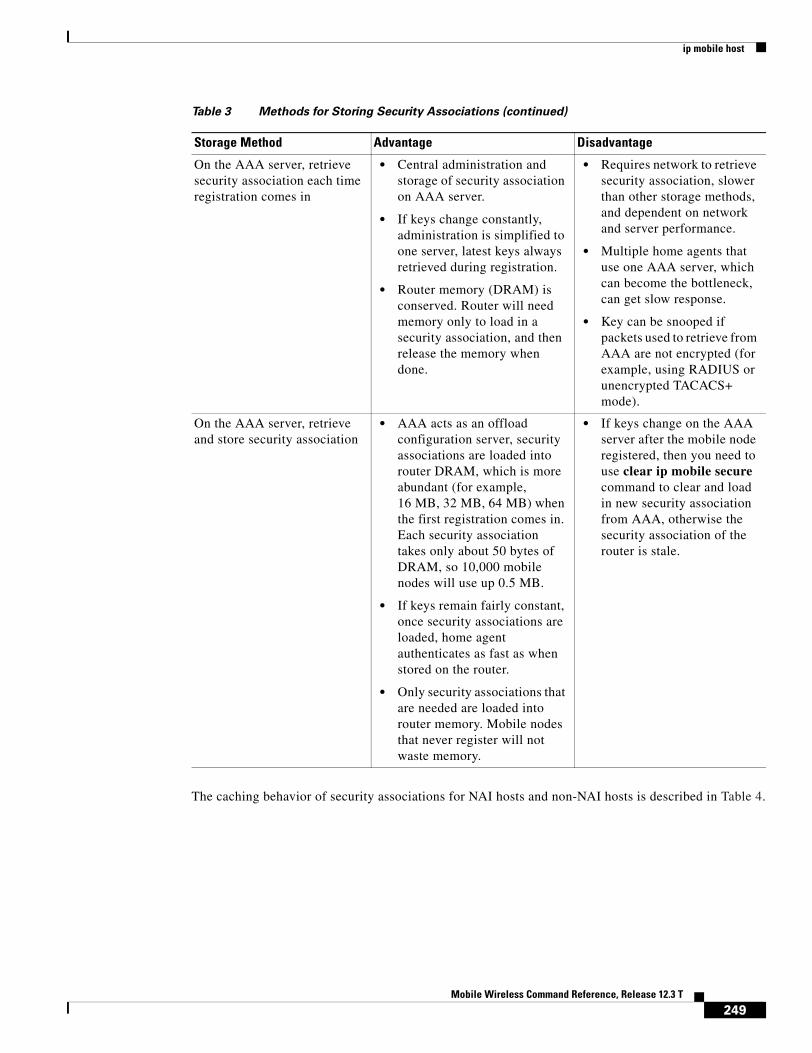
ip mobile host
The caching behavior of security associations for NAI hosts and non-NAI hosts is described in Table 4.
On the AAA server, retrieve security association each time registration comes in
• Central administration and storage of security association on AAA server.
• If keys change constantly, administration is simplified to one server, latest keys always retrieved during registration.
• Router memory (DRAM) is conserved. Router will need memory only to load in a security association, and then release the memory when done.
• Requires network to retrieve security association, slower than other storage methods, and dependent on network and server performance.
• Multiple home agents that use one AAA server, which can become the bottleneck, can get slow response.
• Key can be snooped if packets used to retrieve from AAA are not encrypted (for example, using RADIUS or unencrypted TACACS+ mode).
On the AAA server, retrieve and store security association
• AAA acts as an offload configuration server, security associations are loaded into router DRAM, which is more abundant (for example, 16 MB, 32 MB, 64 MB) when the first registration comes in. Each security association takes only about 50 bytes of DRAM, so 10,000 mobile nodes will use up 0.5 MB.
• If keys remain fairly constant, once security associations are loaded, home agent authenticates as fast as when stored on the router.
• Only security associations that are needed are loaded into router memory. Mobile nodes that never register will not waste memory.
• If keys change on the AAA server after the mobile node registered, then you need to use clear ip mobile secure command to clear and load in new security association from AAA, otherwise the security association of the router is stale.
Table 3 Methods for Storing Security Associations (continued)
Storage Method Advantage Disadvantage
249Mobile Wireless Command Reference, Release 12.3 T
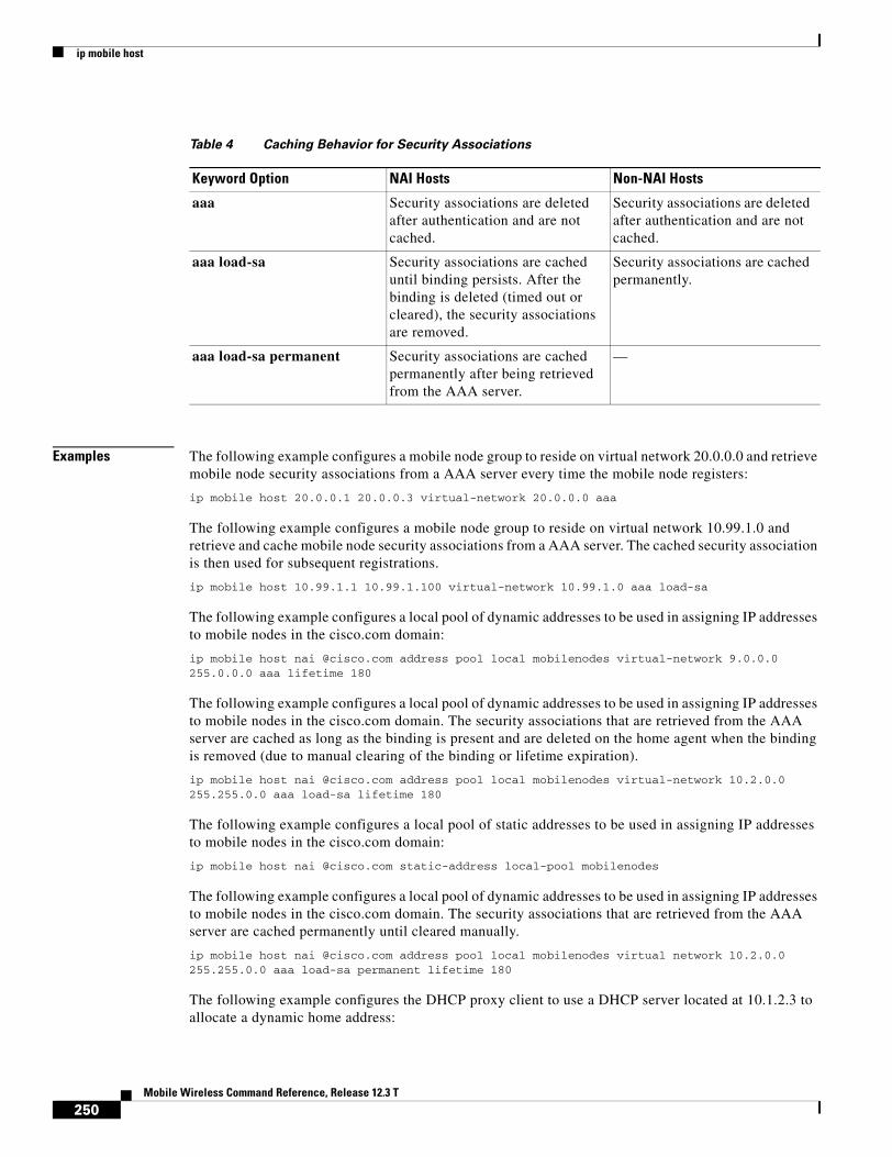
ip mobile host
Examples The following example configures a mobile node group to reside on virtual network 20.0.0.0 and retrieve mobile node security associations from a AAA server every time the mobile node registers:
ip mobile host 20.0.0.1 20.0.0.3 virtual-network 20.0.0.0 aaa
The following example configures a mobile node group to reside on virtual network 10.99.1.0 and retrieve and cache mobile node security associations from a AAA server. The cached security association is then used for subsequent registrations.
ip mobile host 10.99.1.1 10.99.1.100 virtual-network 10.99.1.0 aaa load-sa
The following example configures a local pool of dynamic addresses to be used in assigning IP addresses to mobile nodes in the cisco.com domain:
ip mobile host nai @cisco.com address pool local mobilenodes virtual-network 9.0.0.0 255.0.0.0 aaa lifetime 180
The following example configures a local pool of dynamic addresses to be used in assigning IP addresses to mobile nodes in the cisco.com domain. The security associations that are retrieved from the AAA server are cached as long as the binding is present and are deleted on the home agent when the binding is removed (due to manual clearing of the binding or lifetime expiration).
ip mobile host nai @cisco.com address pool local mobilenodes virtual-network 10.2.0.0 255.255.0.0 aaa load-sa lifetime 180
The following example configures a local pool of static addresses to be used in assigning IP addresses to mobile nodes in the cisco.com domain:
ip mobile host nai @cisco.com static-address local-pool mobilenodes
The following example configures a local pool of dynamic addresses to be used in assigning IP addresses to mobile nodes in the cisco.com domain. The security associations that are retrieved from the AAA server are cached permanently until cleared manually.
ip mobile host nai @cisco.com address pool local mobilenodes virtual network 10.2.0.0 255.255.0.0 aaa load-sa permanent lifetime 180
The following example configures the DHCP proxy client to use a DHCP server located at 10.1.2.3 to allocate a dynamic home address:
Table 4 Caching Behavior for Security Associations
Keyword Option NAI Hosts Non-NAI Hosts
aaa Security associations are deleted after authentication and are not cached.
Security associations are deleted after authentication and are not cached.
aaa load-sa Security associations are cached until binding persists. After the binding is deleted (timed out or cleared), the security associations are removed.
Security associations are cached permanently.
aaa load-sa permanent Security associations are cached permanently after being retrieved from the AAA server.
—
250Mobile Wireless Command Reference, Release 12.3 T
ip mobile host
ip mobile host nai @dhcppool.com address pool dhcp-proxy-client dhcp-server 10.1.2.3 interface FastEthernet 0/0
Related Commands Command Description
aaa authorization ipmobile
Authorizes Mobile IP to retrieve security associations from the AAA server using TACACS+ or RADIUS.
clear ip mobile secure Clears and retrieves remote security associations.
ip mobile proxy-host Locally configures the proxy Mobile IP attributes
ip mobile secure Specifies the mobility security associations for mobile host, visitor, home agent, and foreign agent.
show ip mobile host Displays mobile node counters and information.
251Mobile Wireless Command Reference, Release 12.3 T

ip mobile prefix-length
ip mobile prefix-lengthTo append the prefix-length extension to the advertisement, use the ip mobile prefix-length command in interface configuration mode. To restore the default, use the no form of this command.
ip mobile prefix-length
no ip mobile prefix-length
Syntax Description This command has no arguments or keywords.
Defaults The prefix-length extension is not appended.
Command Modes Interface and Global configuration
Command History
Usage Guidelines The prefix-length extension is used for movement detection. When a mobile node registered with one foreign agent receives an agent advertisement from another foreign agent, the mobile node uses the prefix-length extension to determine whether the advertisements arrived on the same network. The mobile node needs to register with the second foreign agent if it is on a different network. If the second foreign agent is on the same network, reregistration is not necessary.
Examples The following example appends the prefix-length extension to agent advertisements sent by a foreign agent:
ip mobile prefix-length
Related Commands
Release Modification
12.0(1)T This command was introduced.
12.3(11)T Global configuration mode was added.
Command Description
show ip mobile interface
Displays advertisement information for interfaces that are providing foreign agent service or are home links for mobile nodes.
252Mobile Wireless Command Reference, Release 12.3 T

ip mobile registration-lifetime
ip mobile registration-lifetimeTo set the registration lifetime value advertised, use the ip mobile registration-lifetime command in interface or global configuration mode.
ip mobile registration-lifetime seconds
Syntax Description
Defaults 36000 seconds
Command Modes Interface and global configuration
Command History
Usage Guidelines This command allows an administrator to control the advertised lifetime on the interface. The foreign agent uses this command to control duration of registration. Visitors requesting longer lifetimes will be denied.
Examples The following example sets the registration lifetime to 10 minutes on interface Ethernet 1 and 1 hour on interface Ethernet 2:
interface e1ip mobile registration-lifetime 600
interface e2ip mobile registration-lifetime 3600
Related Commands
seconds Lifetime in seconds. Range is from 3 to 65535 (infinity).
Release Modification
12.0(1)T This command was introduced.
12.3(11)T Global configuration mode was added.
Command Description
show ip mobile interface
Displays advertisement information for interfaces that are providing foreign agent service or are home links for mobile nodes.
253Mobile Wireless Command Reference, Release 12.3 T

ip mobile secure host
ip mobile secure hostTo specify the mobility security associations (SAs) for a mobile host, use the ip mobile secure host command in global configuration mode. To remove the mobility SAs, use the no form of this command.
ip mobile secure host {lower-address [upper-address] | nai nai-string} {inbound-spi spi-in outbound-spi spi-out | spi {hex-value | decimal decimal-value}} key {ascii string | hex string} [replay timestamp seconds] [algorithm {md5 mode prefix-suffix | hmac-md5}] [skip-aaa-reauthentication]
no ip mobile secure host {lower-address [upper-address] | nai nai-string} {inbound-spi spi-in outbound-spi spi-out | spi {hex-value | decimal decimal-value}} key {ascii string | hex string} [replay timestamp seconds] [algorithm {md5 mode prefix-suffix | hmac-md5}] [skip-aaa-reauthentication]
Syntax Description lower-address IP address of a host or lower range of IP address pool.
• upper-address—(Optional) Upper range of IP address pool. If specified, SAs for multiple hosts are configured.
Note The upper-address value must be greater than the lower-address value.
nai Network access identifier (NAI) of the mobile node (MN).
• nai-string—NAI username or username@realm.
inbound-spi Bidirectional 4-byte security parameter index (SPI) used for authenticating inbound registration packets.
• spi-in—Index for inbound registration packets. The range is from 100 to ffffffff.
outbound-spi SPI used for calculating the authenticator in outbound registration packets.
• spi-out—Index for outbound registration packets. The range is from 100 to ffffffff.
spi SPI authenticates a peer. The argument and keyword are as follows:
• hex-value—SPI expressed as a hexadecimal number. The range is from 100 to ffffffff.
Note Cisco recommends that you use hexadecimal values instead of decimal values for interoperability.
• decimal—Decimal SPI. The argument is as follows:
– decimal-value—SPI expressed as a decimal number. The range is from 256 to 4294967295.
key Security key. The arguments and keywords are as follows:
• ascii string—Security key expressed as an ASCII string. A maximum of 32 characters is allowed. No spaces are allowed.
• hex string—Security key expressed in hexadecimal digits. A maximum of 32 hex digits is allowed. The range is from 100 to ffffffff. No spaces are allowed.
254Mobile Wireless Command Reference, Release 12.3 T

ip mobile secure host
Defaults No SA is specified for mobile hosts.
Command Modes Global configuration
Command History
Usage Guidelines The SA consists of an entity address, SPI, key, replay protection method, authentication algorithm, and authentication algorithm mode (prefix-suffix).
The SA of a visiting mobile host on the MFAE and the SA of the home agent (HA) on the FHAE are optional as long as they are not specified on the other entity. Multiple SAs for each entity can be configured.
The HMAC-MD5 authentication algorithm is mandatory for MHAE, MFAE, and FHAE.
replay timestamp (Optional) Specifies the number of seconds that the router uses for replay protection.
• seconds—Time, in seconds, that a router uses for replay protection. The range is from plus or minus 255. The default is plus or minus 7.
Note The registration packet is considered “not replayed” if the time stamp in the packet is within plus or minus the configured number of seconds of the router clock.
algorithm (Optional) Algorithm used to authenticate messages during registration. The keywords are as follows:
• md5 mode—Message Digest 5 (MD5) mode used to authenticate packets during registration.
• prefix-suffix—Wrapped registration information for authentication (for example, key registration information key) that calculates the message digest.
Note Cisco no longer recommends this method of authentication, but it is retained for backward compatibility.
• hmac-md5—Hash-based Message Authentication Code (HMAC) MD5.
Note The HMAC-MD5 authentication algorithm or MD5 (prefix-suffix) authentication algorithm is mandatory for mobile-home authentication (MHAE), mobile-foreign authentication (MFAE), or foreign-home authentication (FHAE).
skip-aaa- reauthentication
(Optional) When configured, the home agent does not send an access request for authentication for mobile IP re-registration requests. When disabled, the home agent sends an access request for all Mobile IP registration requests.
Release Modification
12.0(1)T This command was introduced.
12.2 The lower-address and upper-address arguments were added.
12.2(2)XC The nai keyword was added.
12.2(13)T The hmac-md5 keyword was added.
255Mobile Wireless Command Reference, Release 12.3 T

ip mobile secure host
Note NTP is not required for operation, but NTP can be used to synchronize time for all parties.
Examples The following example shows the configuration of an SA for a host:
ip mobile secure host 10.0.0.4 spi 100 key hex 12345678123456781234567812345678
Related Commands Command Description
ip mobile host Configures the mobile host or mobile node group.
ip mobile proxy-host Configures the proxy Mobile IP attributes.
ip mobile secure aaa-download
Configures the rate at which AAA security associations are downloaded.
ip mobile secure foreign-agent
Configures the mobility SAs for an FA.
ip mobile secure home-agent
Configures the mobility SAs for an HA.
ip mobile secure mn-aaa
Specifies non-standard SPI values in the MN-AAA authentication extension that need to be accepted by the home agent or foreign agent.
ip mobile secure proxy-host
Configures the mobility SAs for a proxy host.
ip mobile secure visitor
Configures the mobility SAs for a visitor.
ntp server Allows the system clock to be synchronized by a time server.
show ip mobile secure Displays the mobility SAs for a mobile host, mobile visitor, FA, or HA.
256Mobile Wireless Command Reference, Release 12.3 T

ip probe path
ip probe pathTo enable route probe support on an APN, use the ip probe path access-point configuration command. To return to the default, use the no form of this command.
ip probe path ip_address protocol udp [port port ttl ttl]
no ip probe path ip_address protocol udp [port port ttl ttl]
Syntax Description
Defaults Disabled
Command Modes Access-point configuration
Command History
Usage Guidelines Use the ip probe path access-point configuration command to enable the GGSN to send a probe packet to a specific destination for each PDP context that is successfully established.
An example of how to use this feature is when a firewall load balancer (FWLB) is being used in the network. If the ip probe path command is configured, when a PDP context is established, the GGSN sends a probe packet the FWLB. This enables the FWLB to create an entry for the PDP context even if there is no upstream packet from the MS. Once an entry is created, the FWLB can forward any downstream packet from the network for the MS to the appropriate GGSN without depending on the MS to send the packet first.
Note If an APN is mapped to a VRF, the route probe packet will go through the VRF routing table.
ip_address IP address to which the GGSN is to send a probe packet for each PDP context successfully created.
protocol udp Specifies UDP.
port port (Optional) UDP destination port.
ttl ttl_value (Optional) IP time-to-live (TTL) value for outgoing packet.
Release Modification
12.3(2)XB1 This command was introduced.
12.3(8)T This command was incorporated in Cisco IOS Release 12.3(8)T.
257Mobile Wireless Command Reference, Release 12.3 T

ip rtp compression-connections
ip rtp compression-connectionsTo specify the total number of Real-Time Transport Protocol (RTP) header compression connections that can exist on an interface, use the ip rtp compression-connections command in interface configuration mode. To restore the default value, use the no form of this command.
ip rtp compression-connections number
no ip rtp compression-connections
Syntax Description
Defaults For PPP and High-Level Data Link Control (HDLC) interfaces, the default is 16 compression connections.
For Frame Relay interfaces, the default is 256 compression connections.
Command Modes Interface configuration
Command History
Usage Guidelines You should configure one connection for each RTP call through the specified interface.
Each connection sets up a compression cache entry, so you are in effect specifying the maximum number of cache entries and the size of the cache. Too few cache entries for the specified interface can lead to degraded performance, and too many cache entries can lead to wasted memory.
number Number of RTP header compression connections the cache supports, in the range from 3 to 1000.
Release Modification
11.3 This command was introduced.
12.0(7)T For PPP and HDLC interfaces, the maximum number of compression connections increased from 256 to 1000.
For Frame Relay interfaces, the maximum number of compression connections increased from 32 to 256. The default number of compression connections was increased from 32 (fixed) to 256 (configurable).
12.1(4)E This command was incorporated in Cisco IOS Release 12.1(4)E and was supported on Cisco 7100 series routers.
12.2(8)MC1 This command was incorporated in Cisco IOS Release 12.2(8)MC1 and the maximum number of compression connections for the MGX-RPM-1FE-CP back card was set at 1000.
12.2(8)MC2 This command was incorporated in Cisco IOS Release 12.2(8)MC2 andthe maximum number of compression connections for the MWR 1941-DC was set at 1000.
12.3(11)T This command was incorporated in Cisco IOS Release 12.3(11)T.
258Mobile Wireless Command Reference, Release 12.3 T

ip rtp compression-connections
Note Both ends of the serial connection must use the same number of cache entries.
Note The MGX-RPM-1FE-CP back card supports up to 150 RTP header compression connections on a T1 interface and up to 1000 connections per MLP bundle regardless of whether the bundle contains one T1 interface or four.
Examples The following example changes the number of RTP header compression connections supported to 150:
Router> enableRouter# configure terminalRouter(config)# interface Serial1/0.0Router(config-if)# encapsulation pppRouter(config-if)# ip rtp header-compressionRouter(config-if)# ip rtp compression-connections 150Router(config-if)# exit
Related Commands Command Description
ip rtp header-compression Enables RTP header compression.
show ip rtp header-compression Displays RTP header compression statistics.
259Mobile Wireless Command Reference, Release 12.3 T

ip rtp header-compression
ip rtp header-compressionTo enable Real-Time Transport Protocol (RTP) header compression, use the ip rtp header-compression command in interface configuration mode. To disable RTP header compression, use the no form of this command.
ip rtp header-compression [passive | iphc-format | ietf-format] [periodic-refresh] [ignore-id]
no ip rtp header-compression [passive | iphc-format | ietf-format] [periodic-refresh] [ignore-id]
Syntax Description
Defaults Disabled
For PPP interfaces, the default format for header compression is the IPHC format.
For High-Level Data Link Control (HDLC) and Frame Relay interfaces, the default format for header compression is the original proprietary Cisco format. The maximum number of compression connections for the proprietary Cisco format is 256.
Command Modes Interface configuration
Command History
Usage Guidelines You can compress IP/User Datagram Protocol (UDP)/RTP headers to reduce the size of your packets. Compressing headers is especially useful for RTP because RTP payload size can be as small as 20 bytes, and the uncompressed header is 40 bytes.
passive (Optional) Compresses outgoing RTP packets only if incoming RTP packets on the same interface are compressed. If you do not specify the passive keyword, all RTP packets are compressed. This option is not applicable on PPP links.
iphc-format (Optional) Indicates that the IP Header Compression (IPHC) format of header compression will be used.
ietf-format (Optional) Indicates that the Internet Engineering Task Force (IETF) format of header compression will be used.
periodic-refresh (Optional) Indicates that the compressed IP header will be refreshed periodically.
ignore-id (Optional) Suppresses the IP ID checking in RTP/UDP header compression.
Release Modification
11.3 This command was introduced.
12.0 This command was integrated into Cisco IOS Release 12.0. The iphc-format optional keyword was added.
12.3(2)T This command was integrated into Cisco IOS Release 12.3(2)T and the periodic-refresh optional keyword was added.
12.3(4)T This command was integrated into Cisco IOS Release 12.3(4)T and the ietf-format and ignore-id optional keywords were added.
260Mobile Wireless Command Reference, Release 12.3 T

ip rtp header-compression
Header Compression passive Keyword
By default, the ip rtp header-compression command compresses outgoing RTP traffic. This command includes an optional passive keyword. If you specify the passive keyword, outgoing RTP traffic is compressed only if incoming RTP traffic on the same interface is compressed. If you do not specify the passive keyword, all RTP traffic is compressed.
For PPP interfaces, the passive keyword is ignored. PPP interfaces negotiate the use of header-compression, regardless of whether the passive keyword is specified. Therefore, on PPP interfaces, the passive keyword is replaced by the IPHC format, the default format for PPP interfaces.
Header Compression iphc-format Keyword
This command includes the iphc-format keyword. The iphc-format keyword indicates the type of header compression that will be used. For PPP and HDLC interfaces, when the iphc-format keyword is specified, TCP header-compression is also enabled. For this reason, the ip tcp header-compression command appears in the output of the show running-config command. Since both RTP and TCP header compression are enabled, both UDP and TCP packets are compressed.
The iphc-format keyword includes checking whether the destination port number is even and in the ranges of 16385 to 32767 (for Cisco audio) or 49152 to 65535 (for Cisco video). Valid RTP packets that meet the criteria (that is, the port number is even and within the specified range) are compressed using the compressed RTP packet format. Otherwise, packets are compressed using the less-efficient compressed non-TCP packet format.
Note For Frame Relay interfaces, the iphc-format keyword is not available.
Header Compression ietf-format Keyword
This command includes the ietf-format keyword. The ietf-format keyword indicates the type of header compression that will be used. For HDLC interfaces, the ietf-format compresses only UDP packets. For PPP interfaces, when the ietf-format keyword is specified, TCP header-compression is also enabled. For this reason, the ip tcp header-compression command appears in the output of the show running-config command. Since both RTP and TCP header compression are enabled, both UDP and TCP packets are compressed.
However, with the ietf-format keyword, the requirement of checking whether a destination port number is in a specific range has been removed. Any even destination port number higher than 1024 can be used. Valid RTP packets that meet the criteria (that is, the port number is even and higher than 1024), are compressed using the compressed RTP packet format. Otherwise, packets are compressed using the less-efficient compressed non-TCP packet format.
Note For Frame Relay interfaces, the ietf-format keyword is not available.
Support for Serial Lines
RTP header compression is supported on serial lines using Frame Relay, HDLC, or PPP encapsulation. You must enable compression on both ends of a serial connection.
Unicast or Multicast RTP Packets
This command can compress unicast or multicast RTP packets, and, hence, multicast backbone (MBONE) traffic can also be compressed over slow links. The compression scheme is beneficial only when you have small payload sizes, as in audio traffic.
261Mobile Wireless Command Reference, Release 12.3 T

ip rtp header-compression
Examples The following example enables RTP header compression on the Serial1/0.0 subinterface and limits the number of RTP header compression connections to 10. In this example, the optional iphc-format keyword of the ip rtp header-compression command is specified.
Router> enableRouter# configure terminalRouter(config)# interface Serial1/0.0Router(config-if)# encapsulation pppRouter(config-if)# ip rtp header-compression iphc-formatRouter(config-if)# ip rtp compression-connections 10Router(config-if)# exit
The following example enables RTP header compression on the Serial2/0.0 subinterface and limits the number of RTP header compression connections to 20. In this example, the optional ietf-format keyword of the ip rtp header-compression command is specified.
Router> enableRouter# configure terminalRouter(config)# interface Serial2/0.0Router(config-if)# encapsulation pppRouter(config-if)# ip rtp header-compression ietf-formatRouter(config-if)# ip rtp compression-connections 20Router(config-if)# exit
In the following example, RTP header compression is enabled on the Serial1/0.1 subinterface and the optional periodic-refresh keyword of the ip rtp header-compression command is specified:
Router> enableRouter# configure terminalRouter(config)# interface Serial1/0.1Router(config-if)# encapsulation pppRouter(config-if)# ip rtp header-compression iphc-format periodic-refreshRouter(config-if)# ip rtp compression-connections 10Router(config-if)# exit
Related Commands Command Description
clear ip rtp header-compression Clears RTP header compression structures and statistics.
ip rtp compression-connections Specifies the total number of RTP header compression connections that can exist on an interface.
show ip rtp header-compression Displays RTP header compression statistics.
show running-config Displays the contents of the currently running configuration file or the configuration for a specific interface, or map class information.
262Mobile Wireless Command Reference, Release 12.3 T

ip-access-group
ip-access-group To specify access permissions between an MS and a PDN through the GGSN at a particular access point, use the ip-access-group access-point configuration command. To disable the input access list, use the no form of this command.
ip-access-group access-list-number {in | out}
no ip-access-group access-list-number {in | out}
Syntax Description
Defaults No access list is enforced.
Command Modes Access-point configuration
Command History
Usage Guidelines Use the ip-access-group command to specify an access list that indicates whether users are given or denied permission to access the mobile station from the PDN through the GGSN using a specified access point.
Examples The following example grants access-list 101 inbound access to the mobile station from the PDN through the GGSN:
access-list 101 permit ip 10.0.0.2 0.255.255.255 anyinterface virtual-template 1ip address 172.16.10.1 255.255.255.0no ip directed-broadcastencapsulation gtpgprs access-point-list abc
!gprs access-point-list abcaccess-point 1
access-list-number Number of an access list that has been set up using the access-list command.
in The specified access list controls access from the PDN to the mobile station.
out The specified access list controls access from the mobile station to the PDN.
Release Modification
12.1(1)GA This command was introduced.
12.1(5)T This command was integrated in Cisco IOS Release 12.1(5)T.
12.2(4)MX This command was incorporated in Cisco IOS Release 12.2(4)MX.
12.2(8)YD This command was incorporated in Cisco IOS Release 12.2(8)YD.
12.2(8)B This command was incorporated in Cisco IOS Release 12.2(8)B.
12.3(4)T This command was incorporated in Cisco IOS Release 12.3(4)T.
12.3(8)T This command was incorporated in Cisco IOS Release 12.3(8)T.
263Mobile Wireless Command Reference, Release 12.3 T

ip-access-group
access-point-name gprs.somewhere.comdhcp-server 10.100.0.3ip-access-group 101 inexit
!
264Mobile Wireless Command Reference, Release 12.3 T

ip-address-pool
ip-address-poolTo specify a dynamic address allocation method using IP address pools for the current access point, use the ip-address-pool access-point configuration command. To return to the default value, use the no form of this command.
ip-address-pool {dhcp-proxy-client | radius-client | local pool-name | disable}
no ip-address-pool {dhcp-proxy-client | radius-client | local pool-name | disable}
Syntax Description
Defaults The global setting specified with the gprs default ip-address-pool command is used. The default value for the global configuration command is that IP address pools are disabled.
Command Modes Access-point configuration
Command History
Usage Guidelines You can specify an IP allocation method for an access point in two ways:
• Enter access-point configuration mode and use the ip-address-pool command to specify an IP address allocation method for the current access point.
• Specify a global value for the IP address pool by issuing the gprs default ip-address-pool command. In that case, you do not need to specify an address-pool method for the specific access point.
If you specify dhcp-proxy-client as the method for allocating IP addresses, then you must configure a DHCP server for IP address allocation. You can do this at the global configuration level using the gprs default-dhcp server command, or at the access point level using the dhcp-server command.
dhcp-proxy-client The access-point IP address pool is allocated using a DHCP server.
radius-client The access-point IP address pool is allocated using a RADIUS server.
local The access-point IP address pool is allocated using a locally configured address pool.
disable Disables dynamic address allocation for this access point.
Release Modification
12.1(1)GA This command was introduced.
12.1(5)T This command was integrated in Cisco IOS Release 12.1(5)T.
12.2(4)MX This command was incorporated in Cisco IOS Release 12.2(4)MX.
12.2(8)YD This command was incorporated in Cisco IOS Release 12.2(8)YD.
12.2(8)YW This command was incorporated in Cisco IOS Release 12.2(8)YW.
12.3(2)XB This command was incorporated in Cisco IOS Release 12.3(2)XB and the local option was added.
12.3(4)T This command was incorporated in Cisco IOS Release 12.3(4)T.
12.3(8)T This command was incorporated in Cisco IOS Release 12.3(8)T.
265Mobile Wireless Command Reference, Release 12.3 T

ip-address-pool
If you specify radius-client as the method for allocating IP addresses, then you must configure a RADIUS server for IP address allocation, configure AAA on the GGSN, and configure AAA server groups globally on the GGSN or at the access point. For more information about configuring RADIUS on the GGSN, refer to the Usage Guidelines section for the aaa-group and gprs default aaa-group commands.
Note Configuring a local IP address pool under an APN (using the ip-address-pool local access-point configuration command) improves the PDP context activation rate as the number of PDP contexts increases.
Examples The following example configures DHCP as the IP address pool allocation method for access-point 1 and specifies that the other access points use the global default, which is specified as RADIUS:
aaa new-model!aaa group server radius fooserver 10.2.3.4server 10.6.7.8
aaa group server radius foo1server 10.10.0.1
!aaa authentication ppp foo group fooaaa authentication ppp foo group foo1aaa authorization network default group radius aaa accounting exec default start-stop group fooaaa accounting network foo1 start-stop group foo1!interface Loopback0ip address 10.88.0.1 255.255.255.255
!interface virtual-template 1ip unnumber Loopback0no ip directed-broadcastencapsulation gtpgprs access-point-list abc
!gprs access-point-list abcaccess-point 1access-point-name gprs.pdn1.comip address-pool dhcp-proxy-clientaggregate autodhcp-server 10.100.0.3 dhcp-gateway-address 10.88.0.1exit
!access-point 2access-point-name gprs.pdn2.comaccess-mode non-transparentaaa-group authentication fooexit
!gprs default ip-address-pool radius-client!radius-server host 10.2.3.4 auth-port 1645 acct-port 1646 non-standardradius-server host 10.6.7.8 auth-port 1645 acct-port 1646 non-standardradius-server host 10.10.0.1 auth-port 1645 acct-port 1646 non-standardradius-server key ggsntel
266Mobile Wireless Command Reference, Release 12.3 T

ip-address-pool
Related Commands Command Description
dhcp-server Specifies a primary (and backup) DHCP server to allocate IP addresses to MS users entering a particular PDN access point.
gprs default dhcp-server
Specifies a default DHCP server from which the GGSN obtains IP address leases for mobile users.
gprs default ip-address-pool
Specifies a dynamic address allocation method using IP address pools for the GGSN.
aaa-group Specifies a AAA server group and assigns the type of AAA services to be supported by the server group for a particular access point on the GGSN.
gprs default aaa-group Specifies a default AAA server group and assigns the type of AAA services to be supported by the server group for all access points on the GGSN
267Mobile Wireless Command Reference, Release 12.3 T

keepalive
keepaliveTo enable keepalive packets and to specify the number of times that the Cisco IOS software tries to send keepalive packets without a response before bringing down the interface or before bringing the tunnel protocol down for a specific interface, use the keepalive command in interface configuration mode. When the keepalive function is enabled, a keepalive packet is sent at the specified time interval to keep the interface active. To turn off keepalive packets entirely, use the no form of this command.
keepalive [period [retries]]
no keepalive [period [retries]]
Syntax Description
Defaults period: 10 secondsretries: 5If you enter only the keepalive command with no arguments, defaults for both arguments are used.If you enter only the keepalive command and the timeout parameter, the default number of retries (5) is used.If you enter the no keepalive command, keepalive packets are disabled on the interface.
Command Modes Interface configuration
Command History
Usage Guidelines Keepalive Time Interval
You can configure the keepalive time interval, which is the frequency at which the Cisco IOS software sends messages to itself (Ethernet and Token Ring) or to the other end (serial and tunnel), to ensure that a network interface is alive. The interval is adjustable in 1-second increments down to 1 second. An interface is declared down after three update intervals have passed without receiving a keepalive packet unless the retry value is set higher.
Setting the keepalive timer to a low value is very useful for rapidly detecting Ethernet interface failures (transceiver cable disconnecting, cable not terminated, and so on).
period (Optional) Integer value in seconds greater than 0. The default is 10.
retries (Optional) Specifies the number of times that the device will continue to send keepalive packets without response before bringing the interface down. Integer value greater than 1 and less than 255. If omitted, the value that was previously set is used; if no value was specified previously, the default of 5 is used.
If using this command with a tunnel interface, specifies the number of times that the device will continue to send keepalive packets without response before bringing the tunnel interface protocol down.
Release Modification
10.0 This command was introduced.
12.2(8)T The retries argument was added and made available on tunnel interfaces.
12.2(13)T The default value for the retries argument was increased to 5.
268Mobile Wireless Command Reference, Release 12.3 T

keepalive
Line Failure
A typical serial line failure involves losing Carrier Detect (CD) signal. Because this sort of failure is typically noticed within a few milliseconds, adjusting the keepalive timer for quicker routing recovery is generally not useful.
Keepalive Packets with Tunnel Interfaces
GRE keepalive packets may be sent from both sides of a tunnel, or from just one side. If they are sent from both sides, the period and retry parameters can be different at each side of the link. If you configure keepalives on only one side of the tunnel, the tunnel interface on the sending side might perceive the tunnel interface on the receiving side to be down because the sending interface is not receiving keepalives. From the receiving side of the tunnel, the link appears normal because no keepalives were enabled on the second side of the link.
Dropped Packets
Keepalive packets are treated as ordinary packets, so it is possible that they will be dropped. To reduce the chance that dropped keepalive packets will cause the tunnel interface to be taken down, increase the number of retries.
Note When adjusting the keepalive timer for a very low bandwidth serial interface, large datagrams candelay the smaller keepalive packets long enough to cause the line protocol to go down. You mayneed to experiment to determine the best values to use for the timeout and the number ofretry attempts.
GRE Tunnels with IPSec
When using GRE with IPSec, the keepalives are encrypted like any other traffic. As with user data packets, if the IKE and IPSec security associations are not already active on the GRE tunnel, the first GRE keepalive packet will trigger IKE/IPSec initialization.
Examples The following example shows how to set the keepalive interval to 3 seconds:
Router(config)# interface ethernet 0Router(config-if)# keepalive 3
The following example shows how to set the keepalive interval to 3 seconds and the retry value to 7:
Router(config)# interface tunnel 1Router(config-if)# keepalive 3 7
269Mobile Wireless Command Reference, Release 12.3 T

mode y-cable
mode y-cableTo access the command mode that allows you to manually control the relays on the VWIC card, use the mode y-cable command.
mode y-cable
Syntax Description This command has no parameters, it invokes the y-cable mode.
Defaults There are no default settings or behaviors.
Command Modes Redundancy configuration
Command History
Examples The following example enables y-cable mode.
mode y-cable
Related Commands
Release Modification
12.2(8)MC2 This command was introduced.
12.2(15)MC1 This command was incorporated in Cisco IOS 12.2(15)MC1.
12.3(11)T This command was incorporated in Cisco IOS 12.3(11)T.
Command Description
standalone Indicates whether the MWR 1941-DC router is being used as a standalone device and manually sets the relays.
standby use-interface Designates a loopback interface as a health or revertive interface.
redundancy Invokes redundancy mode.
270Mobile Wireless Command Reference, Release 12.3 T

msisdn suppression
msisdn suppressionTo specify that the GGSN overrides the mobile station integrated services digital network (MSISDN) number with a pre-configured value in its authentication requests to a RADIUS server, use the msisdn suppression access point configuration command. To enable the GGSN to send the MSISDN number in authentication requests to a RADIUS server, use the no form of the command.
msisdn suppression [value]
no msisdn suppression [value]
Syntax Description
Defaults The MSISDN number is suppressed, and no ID string is sent to the RADIUS server in place of the MSISDN number.
Command Modes Access point configuration
Command History
Usage Guidelines Certain countries have privacy laws which prohibit service providers from identifying the MSISDN number of mobile stations in authentication requests. Use the msisdn suppression command to specify a value that the GGSN sends in place of the MSISDN number in its authentication requests to a RADIUS server. If no value is configured, then no number is sent to the RADIUS server.
To use the msisdn suppression command, you must configure a RADIUS server either globally or at the access point and specify non-transparent access mode.
Examples The following example will override the MSISDN ID sent in the create request and will not send any ID to the RADIUS server:
gprs access-point-list abc access-point 1
value (Optional) String (up to 20 characters long) that the GGSN sends in place of the MSISDN number in authentication requests to a RADIUS server. Valid characters for the string are any of those accepted by the MSISDN encoding specifications, including the integers 0–9, and characters a, b, c, * and #. The default value is that no string is sent.
Release Modification
12.2(2) This command was introduced.
12.2(4)MX2 This command was incorporated in Cisco IOS Release 12.2(4)MX2.
12.2(8)YD This command was incorporated in Cisco IOS Release 12.2(8)YD.
12.2(8)B This command was incorporated in Cisco IOS Release 12.2(8)B.
12.3(4)T This command was incorporated in Cisco IOS Release 12.3(4)T.
12.3(8)T This command was incorporated in Cisco IOS Release 12.3(8)T.
271Mobile Wireless Command Reference, Release 12.3 T

msisdn suppression
radius-server 192.168.1.1access-mode non-transparent
msisdn suppression
Related Commands Command Description
access-mode Specifies whether the GGSN requests user authentication at the access point to a PDN.
access-mode Specifies a AAA server group and assigns the type of AAA services to be supported by the server group for a particular access point on the GGSN.
gprs default aaa-group Specifies a default AAA server group and assigns the type of AAA services to be supported by the server group for all access points on the GGSN.
272Mobile Wireless Command Reference, Release 12.3 T

nas
nasTo add an access point or router to the list of devices that use the local authentication server, use the nas command in local RADIUS server configuration mode. To remove the identity of the network access server (NAS) that is configured on the local RADIUS server, use the no form of this command
nas ip-address key shared-key
no nas ip-address key shared-key
Syntax Description
Defaults No default behavior or values
Command Modes Local RADIUS server configuration
Command History
Examples The following command adds the access point having the IP address 192.168.12.17 to the list of devices that use the local authentication server, using the shared key “shared256.”
nas 192.168.12.17 key shared256
Related Commands
ip-address IP address of the access point or router.
key Specifies a key.
shared-key Shared key that is used to authenticate communication between the local authentication server and the access points and routers that use this authenticator.
Release Modification
12.2(11)JA This command was introduced on Cisco Aironet Access Point 1100 and Cisco Aironet Access Point 1200.
12.3(11)T This command was implemented on the following platforms: Cisco 2600XM, Cisco 2691, Cisco 2811, Cisco 2821, Cisco 2851, Cisco 3700, and Cisco 3800 series routers.
Command Description
block count Configures the parameters for locking out members of a group to help protect against unauthorized attacks.
clear radius local-server
Clears the statistics display or unblocks a user.
debug radius local-server
Displays the debug information for the local server.
group Enters user group configuration mode and configures shared setting for a user group.
273Mobile Wireless Command Reference, Release 12.3 T

nas
radius-server host Specifies the remote RADIUS server host.
radius-server local Enables the access point or router to be a local authentication server and enters into configuration mode for the authenticator.
reauthentication time Specifies the time (in seconds) after which access points or wireless-aware routers must reauthenticate the members of a group.
show radius local-server statistics
Displays statistics for a local network access server.
ssid Specifies up to 20 SSIDs to be used by a user group.
user Authorizes a user to authenticate using the local authentication server.
vlan Specifies a VLAN to be used by members of a user group.
Command Description
274Mobile Wireless Command Reference, Release 12.3 T

nbns primary
nbns primaryTo specify a primary (and backup) NBNS to be sent in create PDP responses at the access point, use the nbns primary access-point configuration command. To remove the NBNS from the access-point configuration, use the no form of this command
nbns primary ip-address [secondary ip-address]
Syntax Description
Defaults No default behavior or values.
Command Modes Access-point configuration
Command History
Usage Guidelines Use the nbns primary command to specify the primary (and backup) NBNS at the access point level.
This feature is benefits address allocation schemes where there is no mechanism to obtain these address. Also, for a RADIUS-based allocation scheme, it prevents the operator from having to configure a NBNS and DNS under each user profile.
The NBNS address can come from three possible sources: DHCP server, RADIUS server, or local APN configuration. The criterium for selecting the NBNS address depends on the IP address allocation scheme configured under the APN. Depending on the configuration, the criterium for selecting the DNS and NBNS addresses is as follows:
1. DHCP-based IP address allocation scheme (local and external)—NBNS address returned from the DHCP server is sent to the MS. If the DHCP server does not return an NBNS address, the local APN configuration is used.
2. RADIUS-based IP address allocation scheme—NBNS address returned from the RADIUS server (in Access-Accept responses) is used. If the RADIUS server does not return an NBNS address, the local APN configuration is used.
3. Local IP Address Pool-based IP address allocation scheme—Local APN configuration is used.
4. Static IP Addresses—Local APN configuration is used.
Note The GGSN sends DNS addresses in the create PDP response only if the MS is requesting the DNS address in the PCO IE.
ip-address IP address of the primary NBNS.
secondary ip-address
(Optional) Specifies the IP address of the backup NBNS.
Release Modification
12.3(2)XB This command was introduced.
12.3(8)T This command was incorporated in Cisco IOS Release 12.3(8)T.
275Mobile Wireless Command Reference, Release 12.3 T

nbns primary
Examples The following example specifies a primary and secondary NBNS at the access point level:
access-point 2access-point-name xyz.comnbns primary 10.60.0.1 secondary 10.60.0.2 exit
Related Commands Command Description
ip-address-pool Specifies a dynamic address allocation method using IP address pools for the current access point.
dns primary Specifies a primary (and backup) DNS at the access point level.
276Mobile Wireless Command Reference, Release 12.3 T

network-behind-mobile
network-behind-mobileTo enable an access point to support routing behind the mobile station (MS), use the network-behind-mobile access-point configuration command. To disable support for routing behind the MS, use the no form of this command.
network-behind-mobile
no network-behind-mobile
Syntax Description This command has no arguments or keywords.
Defaults No default behavior or values.
Command Modes Access-point configuration
Command History
Usage Guidelines Use the network-behind-mobile access-point configuration command to enable an access point to support routing behind the MS. The routing behind the MS feature enables the routing of packets to IP addresses that do not belong to the PDP context (the MS), but exist behind it. The network address of the destination can be different than the MS address.
Before enabling routing behind the MS, the following requirements must be met:
• The MS must use RADIUS for authentication and authorization.
• At minimum, one Framed-Route, attribute 22 as defined in Internet Engineering Task Force (IETF) standard RFC 2865, must be configured in the RADIUS server for each MS that wants to use this feature.
When configured, the Framed-Route attribute is automatically downloaded to the GGSN during the authentication and authorization phase of the PDP context creation. If routing behind the MS is not enabled, the GGSN ignores the Framed-Route attribute. If multiple Framed-Route attributes have been configured for an MS, the GGSN uses the first attribute configured. When the MS session is no longer active, the route is deleted.
• For PDP Regen or PPP with L2TP sessions, the Framed-Route attribute must be configure in the RADIUS server of the LNS.
• For PPP Regen sessions, if the security verify source command is configure, the Framed-Route attribute must also be configured in the user profile in the GGSN RADIUS server.Packets routed behind the MS share the same 3GPP QoS settings of the MS.
Release Modification
12.3(8)T This command was introduced.
12.3(8)T This command was incorporated in Cisco IOS Release 12.3(8)T.
277Mobile Wireless Command Reference, Release 12.3 T

network-behind-mobile
Examples The following example shows how to enable support for routing behind the MS at access point 200:
gprs access-point-list abc access-point 200 network-behind-mobile
Related Commands Command Description
security verify Specifies the verification of source and/or destination addresses.
278Mobile Wireless Command Reference, Release 12.3 T
network-request-activation
network-request-activationTo enable an access point to support network-initiated PDP requests, use the network-request-activation access-point configuration command. To disable support for network-initiated PDP requests at an access point, use the no form of this command.
network-request-activation
no network-request-activation
Syntax Description This command has no arguments or keywords.
Defaults No default behavior or values.
Command Modes Access-point configuration
Command History
Usage Guidelines In addition to configuring the network-request-activation command, you must configure the following other commands to support network-initiated PDP requests on the GGSN:
• gprs ni-pdp ip-imsi single
• gprs default map-converting-gsn
Examples The following example shows how to enable support for network-initiated PDP requests at access point 200:
gprs access-point-list abc access-point 200 network-request-activation
Release Modification
12.2(4)MX This command was introduced.
12.2(8)YD This command was incorporated in Cisco IOS Release 12.2(8)YD.
12.2(8)B This command was incorporated in Cisco IOS Release 12.2(8)B.
12.3(4)T This command was incorporated in Cisco IOS Release 12.3(4)T.
12.3(8)T This command was incorporated in Cisco IOS Release 12.3(8)T.
279Mobile Wireless Command Reference, Release 12.3 T
network-request-activation
Related Commands Command Description
gprs ni-pdp ip-imsi single Specifies a static IP address to IMSI mapping for a single MS for network-initiated PDP requests from a particular APN.
gprs default map-converting-gsn
Specifies the address or host name of the SGSN that sends Mobile Application Protocol (MAP) messages to and from the home location register (HLR).
280Mobile Wireless Command Reference, Release 12.3 T

ppp accm
ppp accmTo specify the Asynchronous Control Character Map (ACCM) to be negotiated with a mobile station or sent to a peer in PPP outbound requests, use the ppp accm command in interface configuration mode. To restore the default state, use the no form of this command.
ppp accm hex-number
no ppp accm
Syntax Description
Defaults 0xA0000.
Command Modes Interface configuration
Command History
Usage Guidelines The ACCM is a four octet hexadecimal number that is sent to a peer in a PPP outbound Config-Request packet, informing the peer of which characters need to be escaped during transmission of Asynchronous HDLC (AHDLC) frames containing control characters. The escaped characters set by the ppp accm command are useful for allowing data to pass uninterpreted through a network that would normally interpret the control sequences as a command.
For example, the ^Q and ^S characters are software flow control commands used by asynchronous modems to start and stop data transmissions. To allow these characters to be sent as part of a data stream and not be interpreted as control codes by intervening devices, the characters must be escaped, and the ppp accm command specifies which characters to use.
The TIA/EIA/IS-835-B requires that the PDSN propose an ACCM of 0x00000000. To be compliant with TIA/EIA/IS-835-B, ppp accm 00000000 must be configured on the virtual template interface on Cisco PDSN.
The ppp accm command is meaningful only on asynchronous interfaces. If entered on other interface types, it will be ignored.
hex-number Specifies the initial value for the ACCM. The value must be a hexadecimal number in the range from 0x0 to 0xFFFFFFFF, where the bit positions from right to left correspond to the characters 0x00 through 0x1F. The default character map (0xA0000) escapes the characters represented by 0x11 (^Q, DC1, and X-on) and 0x13 (^S, DC3, and X-off).
Note The leading 0x is not necessary when entering the hex-number argument , but is accepted by the software.
Release Modification
12.1(3)XS This command was introduced.
12.2 This command was integrated into Cisco IOS Release 12.2.
281Mobile Wireless Command Reference, Release 12.3 T
ppp accm
Examples In the following example, all characters can be transmitted intact to the receiver so that it is not necessary for the transmitter to escape anything:
interface async 0 encapsulation ppp ppp accm 0
Related Commands Command Description
ppp authentication Specifies CHAP or PAP authentication.
282Mobile Wireless Command Reference, Release 12.3 T

ppp authentication
ppp authenticationTo enable at least one PPP authentication protocol and to specify the order in which the protocols are selected on the interface, use the ppp authentication command in interface configuration mode. To disable this authentication, use the no form of this command.
ppp authentication {protocol1 [protocol2...]} [if-needed] [list-name | default] [callin] [one-time] [optional]
no ppp authentication
Syntax Description
Defaults PPP authentication is not enabled.
Command Modes Interface configuration
Command History
protocol1 [protocol2...] At least one of the keywords described in Table 5.
if-needed (Optional) Used with TACACS and extended TACACS. Does not perform Challenge Handshake Authentication Protocol (CHAP) or Password Authentication Protocol (PAP) authentication if authentication has already been provided. This option is available only on asynchronous interfaces.
list-name (Optional) Used with authentication, authorization, and accounting (AAA). Specifies the name of a list of methods of authentication to use. If no list name is specified, the system uses the default. The list is created with the aaa authentication ppp command.
default (Optional) Name of the method list created with the aaa authentication ppp command.
callin (Optional) Authentication on incoming (received) calls only.
one-time (Optional) The username and password are accepted in the username field.
optional (Optional) Accepts the connection even if the peer refuses to accept the authentication methods that the router has requested.
Release Modification
10.0 This command was introduced.
12.1(1) The optional keyword was added.
12.1(3)XS The optional keyword was added.
12.2(2)XB5 Support for the eap authentication protocol was added on the Cisco 2650, Cisco 3640, Cisco 3660, Cisco AS5300, and Cisco AS5400 platforms.
12.2(13)T The eap authentication protocol support introduced in Cisco IOS Release 12.2(2)XB5 was integrated into Cisco IOS Release 12.2(13)T.
283Mobile Wireless Command Reference, Release 12.3 T

ppp authentication
Usage Guidelines When you enable PAP, CHAP, or Extensible Authentication Protocol (EAP) authentication (or all three methods), the local router requires the remote device to prove its identity before allowing data traffic to flow. PAP authentication requires the remote device to send a name and a password, which is checked against a matching entry in the local username database or in the remote security server database. CHAP authentication sends a challenge message to the remote device. The remote device encrypts the challenge value with a shared secret and returns the encrypted value and its name to the local router in a Response message. The local router attempts to match the name of the remote device with an associated secret stored in the local username or remote security server database; it uses the stored secret to encrypt the original challenge and verify that the encrypted values match. EAP works much as CHAP does, except that identity request and response packets are exchanged when EAP starts.
You can enable CHAP, Microsoft CHAP (MS-CHAP), PAP, or EAP in any order. If you enable all four methods, the first method specified is requested during link negotiation. If the peer suggests using the second method, or refuses the first method, the second method is tried. Some remote devices support only one method. Base the order in which you specify methods on the ability of the remote device to correctly negotiate the appropriate method and on the level of data-line security you require. PAP usernames and passwords are sent as clear text strings, which can be intercepted and reused.
Caution If you use a list-name value that was not configured with the aaa authentication ppp command, you will disable PPP on this interface.
Table 5 lists the protocols used to negotiate PPP authentication.
Enabling or disabling PPP authentication does not affect the ability of the local router to authenticate itself to the remote device.
If you are using autoselect on a tty line, you can use the ppp authentication command to turn on PPP authentication for the corresponding interface.
MS-CHAP is the Microsoft version of CHAP. Like the standard version of CHAP, MS-CHAP is used for PPP authentication; authentication occurs between a personal computer using Microsoft Windows NT or Microsoft Windows 95 and a Cisco router or access server acting as a network access server.
To configure Cisco PDSN in compliance with the TIA/EIA/IS-835-B standard, you must configure the PDSN virtual template as follows:
ppp authentication chap pap optional
Examples The following example configures virtual-template interface 4:
interface virtual-template 4 ip unnumbered loopback0 ppp authentication chap pap optional
Table 5 ppp authentication Protocols
chap Enables CHAP on a serial interface.
eap Enables EAP on a serial interface.
ms-chap Enables MS-CHAP on a serial interface.
pap Enables PAP on a serial interface.
284Mobile Wireless Command Reference, Release 12.3 T

ppp authentication
The following example enables CHAP on asynchronous interface 4 and uses the authentication list MIS-access:
interface async 4encapsulation pppppp authentication chap MIS-access
The following example enables EAP on dialer interface 1:
interface dialer 1encapsulation pppppp authentication eap
Related Commands Command Description
aaa authentication ppp Specifies one or more AAA authentication methods for use on serial interfaces running PPP.
aaa new-model Enables the AAA access control model.
autoselect Configures a line to start an ARAP, PPP, or SLIP session.
encapsulation Sets the encapsulation method used by the interface.
ppp accm Identifies the ACCM table.
username Establishes a username-based authentication system, such as PPP, CHAP, and PAP.
285Mobile Wireless Command Reference, Release 12.3 T

ppp mux
ppp muxTo enable PPP multiplexing/demultiplexing, use the ppp mux command in interface configuration mode. To disable PPP multiplexing/demultiplexing, use the no form of this command.
ppp mux
no ppp mux
Syntax Description This command has no parameters.
Defaults PPP multiplexing/demultiplexing is disabled by default.
Command Modes Interface configuration
Command History
Examples The following example enables PPP multiplexing/demultiplexing.
ppp mux
Related Commands
Release Modification
12.2(8)MC1 This command was introduced (MGX-RPM-1FE-CP back card).
12.2(8)MC2 This command was introduced (MWR 1941-DC router).
12.3(11)T This command was incorporated in Cisco IOS 12.3(11)T.
Command Description
ppp mux delay Sets the maximum delay.
ppp mux frame Sets the maximum length of the PPP superframe.
ppp mux pid Sets the default PPP protocol ID.
ppp mux subframe count Sets the maximum number of subframes in a superframe.
ppp mux subframe length Sets the maximum length of the PPP subframe.
show ppp mux Displays PPP mux counters for the specified multilink interface.
286Mobile Wireless Command Reference, Release 12.3 T

ppp mux delay
ppp mux delayTo set the maximum time the processor can wait before sending a superframe, use the ppp mux delay command in interface configuration mode. To set the maximum delay to the default, use the no form of this command.
ppp mux delay integer
no ppp mux delay
Syntax Description
Defaults Cisco MWR 1941-DC router—The default maximum delay is 0, which indicates that a superframe will be sent when the transmit queue is full.
MGX-RPM-1FE-CP back card—The default maximum delay is 800.
Command Modes Interface configuration
Command History
Usage Guidelines To use this command, you must first enable PPP multiplexing/demultiplexing.
MGX-RPM-1FE-CP Back Card
When the ppp mux delay command is configured, the maximum number of microseconds that the processor can wait resolves to the nearest 200-microsecond increment. For example, if ppp mux delay 302 is specified, the actual maximum number of microseconds that the processor can wait before sending out a PPP superframe is 400. If ppp mux delay 298 is specified, the actual maximum number of microseconds that the processor can wait before sending out a PPP superframe is 200.
integer The maximum number of microseconds that the processor can wait before sending out a PPP superframe.
Possible values:
• Cisco MWR 1941-DC router—0 through 4000000 microseconds.
• MGX-RPM-1FE-CP back card—1 through 4000000 microseconds.
Release Modification
12.2(8)MC1 This command was introduced (MGX-RPM-1FE-CP back card).
12.2(8)MC2 This command was introduced (MWR 1941-DC router).
12.3(11)T This command was incorporated in Cisco IOS 12.3(11)T.
287Mobile Wireless Command Reference, Release 12.3 T

ppp mux delay
Examples The following example sets the maximum delay to 5 microseconds on the MWR 1941-DC router.
ppp mux delay 5
The following example sets the maximum delay to 200 microseconds on the MGX-RPM-1FE-CP back card.
ppp mux delay 200
Related Commands Command Description
ppp mux Enables PPP multiplexing/demultiplexing
ppp mux frame Sets the maximum length of the PPP superframe.
ppp mux pid Sets the default PPP protocol ID.
ppp mux subframe count Sets the maximum number of subframes in a superframe.
ppp mux subframe length Sets the maximum length of the PPP subframe.
show ppp mux Displays PPP mux counters for the specified multilink interface.
288Mobile Wireless Command Reference, Release 12.3 T
ppp mux frame
ppp mux frameTo set the maximum length (in bytes) of the PPP superframes, use the ppp mux frame command in interface configuration mode. To set the maximum length to the default, use the no form of this command.
ppp mux frame integer
no ppp mux frame
Syntax Description
Defaults The default maximum length is 197.
Command Modes Interface configuration
Command History
Usage Guidelines To use this command, you must first enable PPP multiplexing/demultiplexing.
Examples The following example sets the maximum superframe length to 80 bytes.
ppp mux frame 80
Related Commands
integer The maximum number of bytes in any multiplexed PPP superframe.
Possible values:
• Cisco MWR 1941-DC router—1 through 512 bytes.
• MGX-RPM-1FE-CP back card—0 through 512 bytes.
Release Modification
12.2(8)MC1 This command was introduced (MGX-RPM-1FE-CP back card).
12.2(8)MC2 This command was introduced (MWR 1941-DC router).
12.3(11)T This command was incorporated in Cisco IOS 12.3(11)T.
Command Description
ppp mux Enables PPP multiplexing/demultiplexing
ppp mux delay Sets the maximum delay.
ppp mux pid Sets the default PPP protocol ID.
ppp mux subframe count Sets the maximum number of subframes in a superframe.
ppp mux subframe length Sets the maximum length of the PPP subframe.
show ppp mux Displays PPP mux counters for the specified multilink interface.
289Mobile Wireless Command Reference, Release 12.3 T
ppp mux pid
ppp mux pidTo set the default receiving PPP protocol ID, use the ppp mux pid command in interface configuration mode. To remove this configuration, use the no form of this command.
ppp mux pid integer
no ppp mux pid
Syntax Description
Defaults The default is 33 (0x21), which is the IP protocol.
Command Modes Interface configuration
Command History
Usage Guidelines To use this command, you must first enable PPP multiplexing/demultiplexing.
Examples The following example sets the default PPP protocol ID to 8.
ppp mux pid 8
Related Commands
integer The default value of the PPP protocol ID. Possible values are 0 through 65534.
Release Modification
12.2(8)MC1 This command was introduced (MGX-RPM-1FE-CP back card).
12.2(8)MC2 This command was introduced (MWR 1941-DC router).
12.3(11)T This command was incorporated in Cisco IOS 12.3(11)T.
Command Description
ppp mux Enables PPP multiplexing/demultiplexing
ppp mux delay Sets the maximum delay.
ppp mux frame Sets the maximum length of the PPP superframe.
ppp mux subframe count Sets the maximum number of subframes in a superframe.
ppp mux subframe length Sets the maximum length of the PPP subframe.
show ppp mux Displays PPP mux counters for the specified multilink interface.
290Mobile Wireless Command Reference, Release 12.3 T

ppp mux subframe count
ppp mux subframe countTo set the maximum number of PPP subframes that can be contained in a superframe, use the ppp mux subframe count command in interface configuration mode. To set the maximum number to the default, use the no form of this command.
ppp mux subframe count integer
no ppp mux subframe count
Syntax Description
Defaults The default maximum is 15.
Command Modes Interface configuration
Command History
Usage Guidelines To use this command, you must first enable PPP multiplexing/demultiplexing.
Examples The following example sets the maximum subframe count to 20 bytes.
ppp mux subframe count 20
Related Commands
integer The maximum number of subframes that can be contained in a superframe. Possible values are 1 through 15 bytes.
Possible values:
• Cisco MWR 1941-DC router—1 through 15 bytes.
• MGX-RPM-1FE-CP back card—0 through 15 bytes.
Release Modification
12.2(8)MC1 This command was introduced (MGX-RPM-1FE-CP back card).
12.2(8)MC2 This command was introduced (MWR 1941-DC router).
12.3(11)T This command was incorporated in Cisco IOS 12.3(11)T.
Command Description
ppp mux Enables PPP multiplexing/demultiplexing
ppp mux delay Sets the maximum delay.
ppp mux frame Sets the maximum length of the PPP superframe.
ppp mux pid Sets the default PPP protocol ID.
291Mobile Wireless Command Reference, Release 12.3 T

ppp mux subframe count
ppp mux subframe length Sets the maximum length of the PPP subframe.
show ppp mux Displays PPP mux counters for the specified multilink interface.
Command Description
292Mobile Wireless Command Reference, Release 12.3 T

ppp mux subframe length
ppp mux subframe lengthTo set the maximum length (in bytes) of the PPP subframes, use the ppp mux subframe length command in interface configuration mode. To set the maximum length to the default, use the no form of this command.
ppp mux subframe length integer
no ppp mux subframe length
Syntax Description
Defaults The default maximum length is 195.
Command Modes Interface configuration
Command History
Usage Guidelines To use this command, you must first enable PPP multiplexing/demultiplexing. The maximum length of the subframe should be the maximum length of the superframe minus the length of the L2 header.
Examples The following example sets the maximum subframe length to 20 bytes.
ppp mux subframe length 20
Related Commands
integer The maximum number of bytes in any single subframe that is to be multiplexed.
Possible values:
• Cisco MWR 1941-DC router—1 through 512 bytes.
• MGX-RPM-1FE-CP back card—0 through 512 bytes.
Release Modification
12.2(8)MC2 This command was introduced.
12.3(11)T This command was incorporated in Cisco IOS 12.3(11)T.
Command Description
ppp mux Enables PPP multiplexing/demultiplexing
ppp mux delay Sets the maximum delay.
ppp mux frame Sets the maximum length of the PPP superframe.
ppp mux pid Sets the default PPP protocol ID.
ppp mux subframe count Sets the maximum number of subframes in a superframe.
show ppp mux Displays PPP mux counters for the specified multilink interface.
293Mobile Wireless Command Reference, Release 12.3 T

ppp-regeneration
ppp-regenerationTo enable an access point to support PPP regeneration, use the ppp-regeneration access-point configuration command. To disable support for PPP regeneration at an access point, use the no form of this command.
ppp-regeneration [max-session number] [setup-time seconds]
no ppp-regeneration [max-session number] [setup-time seconds]
Syntax Description
Defaults The default max-session value is 65535.
The default setup-time is 60 seconds.
Command Modes Access-point configuration
Command History
Usage Guidelines Use the ppp-regeneration command to enable an access point to support PPP regeneration and to specify parameters for PPP regeneration sessions on the GGSN.
Note PPP regeneration support at an access point requires CEF to be enabled on the RP using the ip cef command.
The maximum setup-time value should allow for the total amount of time required to create the PPP virtual access (VA) and to establish a PPP session. If the setup-time is reached before the PPP IP Control Protocol (IPCP) is up, the GGSN tears down the L2TP session, PPP VA, and PDP context.
The method of PPP configured to forward packets beyond the terminal equipment and mobile termination affects the maximum number of PDP contexts supported on the GGSN. For more information, see the “Configuring PPP Support on the GGSN” chapter of the Cisco IOS Mobile Wireless Configuration Guide for Cisco IOS Release 12.2(8)YD.
max-session number Maximum number of PPP regenerated sessions allowed at the access point. The default value 65535.
setup-time seconds Maximum amount of time (between 1 and 65535 seconds) within which a PPP regenerated session must be established. The default value is 60 seconds.
Release Modification
12.2(4)MX This command was introduced.
12.2(8)YD This command was incorporated in Cisco IOS Release 12.2(8)YD and the default value changed from being device dependent to 65535.
12.2(8)B This command was incorporated in Cisco IOS Release 12.2(8)B.
12.3(4)T This command was incorporated in Cisco IOS Release 12.3(4)T.
12.3(8)T This command was incorporated in Cisco IOS Release 12.3(8)T.
294Mobile Wireless Command Reference, Release 12.3 T

ppp-regeneration
Examples The following example shows a partial GGSN configuration for PPP regeneration, where PPP regeneration is enabled at access point 1. It specifies a maximum of 100 PPP regeneration sessions, with a limit of 30 seconds to create the PPP VA and establish a PPP session:
gprs access-point-list abcaccess-point 1access-point-name gprs.corporate.comppp-regeneration max-session 100 setup-time 30exit
Related Commands Command Description
gprs gtp ppp-regeneration vtemplate
Associates the virtual template interface that is configured for PPP encapsulation with support for regenerated PPP sessions on the GGSN.
interface virtual-template Creates a virtual template interface that can be configured and applied dynamically in creating virtual access interfaces.
295Mobile Wireless Command Reference, Release 12.3 T
radius attribute nas-id
radius attribute nas-idTo specify that the GGSN include the NAS-Identifier (attribute 32) in access requests at an APN, use the following access-point configurationcommand. To disable this configuration, use the no form of this command.
radius attribute nas-id format
no radius attribute nas-id
Syntax Description
Defaults The default is to not send the NAS-Identifier in access requests.
Command Modes Access point configuration
Command History
Usage Guidelines Use the radius attribute nas-id command to include the NAS-Identifier in access requests at an APN.
This command overrides the configuration of the radius-server attribute 32 include-in-access-req format global configuration command.
Examples The following example configures the GGSN to send the NAS-Identifier in access requests at the APN:
gprs access-point-list abc access-point 1 radius attribute nas-id %h
Related Commands
format String sent in attribute 32 containing an IP address (%i), a hostname (%h), and a domain name (%d).
Release Modification
12.3(2)XB This command was introduced.
12.3(8)T This command was incorporated in Cisco IOS Release 12.3(8)T.
Command Description
access-mode Specifies whether the GGSN requests user authentication at the access point to a PDN.
aaa-group Specifies a AAA server group and assigns the type of AAA services to be supported by the server group for a particular access point on the GGSN.
gprs default aaa-group Specifies a default AAA server group and assigns the type of AAA services to be supported by the server group for all access points on the GGSN.
show gprs access-point Displays information about access points on the GGSN.
296Mobile Wireless Command Reference, Release 12.3 T

radius attribute suppress imsi
radius attribute suppress imsiTo specify that the GGSN suppress the Third Generation Partnership Project (3GPP) vendor-specific attribute (VSA) 3GGP-IMSI number in its authentication and accounting requests to a RADIUS server, use the radius attribute suppress imsi access point configuration command. To enable the GGSN to send the 3GPP VSA 3GPP-IMSI number in authentication and accounting requests to a RADIUS server, use the no form of the command.
radius attribute suppress imsi
no radius attribute suppress imsi
Syntax Description This command has no arguments or keywords.
Defaults The default is to send the 3GPP VSA 3GPP-IMSI number in authentication and accounting requests to a RADIUS server.
Command Modes Access point configuration
Command History
Usage Guidelines Use the radius attribute suppress imsi command to have GGSN suppress the 3GPP VSA 3GPP-IMSI number in its authentication and accounting requests to a RADIUS server.
Examples The following example will not send the 3GPP VSA 3GPP-IMSI to the RADIUS server:
gprs access-point-list abc access-point 1 radius attribute suppress imsi
Related Commands
Release Modification
12.2(8)YD This command was introduced.
12.2(8)B This command was incorporated in Cisco IOS Release 12.2(8)B.
12.3(4)T This command was incorporated in Cisco IOS Release 12.3(4)T.
12.3(8)T This command was incorporated in Cisco IOS Release 12.3(8)T.
Command Description
access-mode Specifies whether the GGSN requests user authentication at the access point to a PDN.
aaa-group Specifies a AAA server group and assigns the type of AAA services to be supported by the server group for a particular access point on the GGSN.
297Mobile Wireless Command Reference, Release 12.3 T

radius attribute suppress imsi
gprs default aaa-group Specifies a default AAA server group and assigns the type of AAA services to be supported by the server group for all access points on the GGSN.
show gprs access-point Displays information about access points on the GGSN.
Command Description
298Mobile Wireless Command Reference, Release 12.3 T

radius attribute suppress qos
radius attribute suppress qosTo specify that the GGSN suppress the 3GPP VSA 3GPP-GPRS-QoS-Profile in its authentication and accounting requests to a RADIUS server, use the radius attribute suppress qos access point configuration command. To enable the GGSN to send the 3GPP VSA 3GPP-GPRS-QoS-Profile in authentication and accounting requests to a RADIUS server, use the no form of the command.
radius attribute suppress qos
no radius attribute suppress qos
Syntax Description This command has no arguments or keywords.
Defaults The default is to send the 3GPP VSA 3GPP-GPRS-QoS-Profile in authentication and accounting requests to a RADIUS server.
Command Modes Access point configuration
Command History
Usage Guidelines Use the radius attribute suppress qos command to have GGSN suppress the 3GPP VSA 3GPP-GPRS-QoS-Profile in its authentication and accounting requests to a RADIUS server.
Examples The following example will not send the 3GPP VSA 3GPP-GPRS-QoS-Profile to the RADIUS server:
gprs access-point-list abc access-point 1 radius attribute suppress qos
Related Commands
Release Modification
12.2(8)B This command was introduced.
12.3(4)T This command was incorporated in Cisco IOS Release 12.3(4)T.
12.3(8)T This command was incorporated in Cisco IOS Release 12.3(8)T.
Command Description
access-mode Specifies whether the GGSN requests user authentication at the access point to a PDN.
aaa-group Specifies a AAA server group and assigns the type of AAA services to be supported by the server group for a particular access point on the GGSN.
gprs default aaa-group Specifies a default AAA server group and assigns the type of AAA services to be supported by the server group for all access points on the GGSN.
show gprs access-point Displays information about access points on the GGSN.
299Mobile Wireless Command Reference, Release 12.3 T

radius attribute suppress sgsn-address
radius attribute suppress sgsn-addressTo specify that the GGSN suppress the 3GPP VSA 3GPP-SGSN-Address in its authentication and accounting requests to a RADIUS server, use the radius attribute suppress sgsn-address access point configuration command. To enable the GGSN to send the 3GPP VSA 3GPP-SGSN-Address in authentication and accounting requests to a RADIUS server, use the no form of the command.
radius attribute suppress sgsn-address
no radius attribute suppress sgsn-address
Syntax Description This command has no arguments or keywords.
Defaults The default is to send the 3GPP VSA 3GPP-SGSN-Address in authentication and accounting requests to a RADIUS server.
Command Modes Access point configuration
Command History
Usage Guidelines Use the radius attribute suppress sgsn-address command to have GGSN suppress the 3GPP VSA 3GPP-SGSN-Address in its authentication and accounting requests to a RADIUS server.
Examples The following example will not send the 3GPP VSA 3GPP-SGSN-Address to the RADIUS server:
gprs access-point-list abc access-point 1 radius attribute suppress sgsn-address
Related Commands
Release Modification
12.2(8)B This command was introduced.
12.3(4)T This command was incorporated in Cisco IOS Release 12.3(4)T.
12.3(8)T This command was incorporated in Cisco IOS Release 12.3(8)T.
Command Description
access-mode Specifies whether the GGSN requests user authentication at the access point to a PDN.
aaa-group Specifies a AAA server group and assigns the type of AAA services to be supported by the server group for a particular access point on the GGSN.
gprs default aaa-group Specifies a default AAA server group and assigns the type of AAA services to be supported by the server group for all access points on the GGSN.
show gprs access-point Displays information about access points on the GGSN.
300Mobile Wireless Command Reference, Release 12.3 T

radius-server local
radius-server localTo enable the access point or wireless-aware router as a local authentication server and to enter into configuration mode for the authenticator, use the radius-server local command in global configuration mode. To remove the local RADIUS server configuration from the router or access point, use the no form of this command.
radius-server local
no radius-server local
Syntax Description This command has no arguments or keywords.
Defaults No default behavior or values
Command Modes Global configuration
Command History
Examples The following example shows that the access point is being configured to serve as a local authentication server:
Router (config)# radius-server local
Related Commands
Release Modification
12.2(11)JA This command was introduced on Cisco Aironet Access Point 1100 and Cisco Aironet Access Point 1200.
12.3(11)T This command was implemented on the following platforms: Cisco 2600XM, Cisco 2691, Cisco 2811, Cisco 2821, Cisco 2851, Cisco 3700, and Cisco 3800 series routers.
Command Description
block count Configures the parameters for locking out members of a group to help protect against unauthorized attacks.
clear radius local-server
Clears the statistics display or unblocks a user.
debug radius local-server
Displays the debug information for the local server.
group Enters user group configuration mode and configures shared setting for a user group.
nas Adds an access point or router to the list of devices that use the local authentication server.
radius-server host Specifies the remote RADIUS server host.
301Mobile Wireless Command Reference, Release 12.3 T
radius-server local
reauthentication time Specifies the time (in seconds) after which access points or wireless-aware routers must reauthenticate the members of a group.
show radius local-server statistics
Displays statistics for a local network access server.
ssid Specifies up to 20 SSIDs to be used by a user group.
user Authorizes a user to authenticate using the local authentication server.
vlan Specifies a VLAN to be used by members of a user group.
Command Description
302Mobile Wireless Command Reference, Release 12.3 T

reauthentication time
reauthentication timeTo enter the time limit after which the authenticator should reauthenticate, use the reauthentication time command in local RADIUS server group configuration mode. To remove the requirement that users reauthenticate after the specified duration, use the no form of this command.
reauthentication time seconds
no reauthentication time seconds
Syntax Description
Defaults The default setting is 0 seconds, which means that group members are not required to reauthenticate.
Command Modes Local RADIUS server group configuration
Command History
Examples The following example shows that the time limit after which the authenticator should reauthenticate is 30 seconds:
reauthentication time 30
Related Commands
seconds Number of seconds after which reauthentication occurs.
Release Modification
12.2(11)JA This command was introduced on Cisco Aironet Access Point 1100 and Cisco Aironet Access Point 1200.
12.3(11)T This command was implemented on the following platforms: Cisco 2600XM, Cisco 2691, Cisco 2811, Cisco 2821, Cisco 2851, Cisco 3700, and Cisco 3800 series routers.
Command Description
block count Configures the parameters for locking out members of a group to help protect against unauthorized attacks.
clear radius local-server
Clears the statistics display or unblocks a user.
debug radius local-server
Displays the debug information for the local server.
group Enters user group configuration mode and configures shared setting for a user group.
nas Adds an access point or router to the list of devices that use the local authentication server.
radius-server host Specifies the remote RADIUS server host.
303Mobile Wireless Command Reference, Release 12.3 T

reauthentication time
radius-server local Enables the access point or router to be a local authentication server and enters into configuration mode for the authenticator.
show radius local-server statistics
Displays statistics for a local network access server.
ssid Specifies up to 20 SSIDs to be used by a user group.
user Authorizes a user to authenticate using the local authentication server.
vlan Specifies a VLAN to be used by members of a user group.
Command Description
304Mobile Wireless Command Reference, Release 12.3 T

redirect all ip
redirect all ipTo redirect all traffic to an external device, use the redirect all ip access-point configuration command. To disable the redirection of all traffic, use the no form of this command.
redirect intermobile ip ip-address
no redirect intermobile ip ip-address
Syntax Description
Defaults Disabled
Command Modes Access-point configuration
Command History
Usage Guidelines Use the redirect all ip access-point command to redirect all traffic to an IP address.
The redirect all traffic feature enables you to do the following:
• Redirect all packets to a specified destination regardless of whether the destination address belongs to a mobile station (MS) on the same GGSN or not.
If redirecting traffic using the Mobile-to-Mobile Redirect feature, only packets for which the destination address belongs to an MS that is active on the same GGSN can be redirected. If the receiving MS has no PDP context in the GGSN where the sending MS PDP context is created, the packets are dropped.
• Redirect all traffic to a specific destination when aggregate routes are configured..
Examples The following example redirects traffic to 5.5.5.13:
redirect all ip 5.5.5.13
Related Commands
ip-address IP address to where you want to redirect traffic.
Release Modification
12.3(2)XB2 This command was introduced.
12.3(8)T This command was incorporated in Cisco IOS Release 12.3(8)T.
Command Description
gprs plmn ip address Specifies the IP address range of a PLMN.
security verify Specifies the verification of source and/or destination addresses.
305Mobile Wireless Command Reference, Release 12.3 T
redirect intermobile ip
redirect intermobile ipTo redirect mobile-to-mobile traffic to an external device, use the redirect intermobile interface ip access-point configuration command. To disable the redirection of mobile-to-mobile traffic, use the no form of this command.
redirect intermobile ip ip-address
no redirect intermobile ip ip-address
Syntax Description
Defaults Disabled
Command Modes Access-point configuration
Command History
Usage Guidelines Use the redirect intermobile ip access-point command to redirect mobile-to-mobile traffic to an external device (such as an external firewall) for verification.
Redirection of intermobile traffic does not occur on an ingress APN unless the TPDUs are exiting the same APN. In addition, redirection of TPDUs tunneled by L2TP from the ingress APN to the LNS of the PDN does not occur.
Note Redirection of intermobile traffic does not occur on an ingress APN unless the TPDUs are exiting the same APN. In addition, redirection of TPDUs tunneled by L2TP from the ingress APN to the LNS of the PDN does not occur.
Examples The following example redirects mobile-to-mobile traffic to 5.5.5.13:
redirect intermobile ip 5.5.5.13
Related Commands
ip-address IP address of the external device to which you want to redirect mobile-to-mobile traffic.
Release Modification
12.2(8)B This command was introduced.
12.3(4)T This command was incorporated in Cisco IOS Release 12.3(4)T.
12.3(8)T This command was incorporated in Cisco IOS Release 12.3(8)T.
Command Description
gprs plmn ip address Specifies the IP address range of a PLMN.
security verify Specifies the verification of source and/or destination addresses.
306Mobile Wireless Command Reference, Release 12.3 T

redundancy
redundancyTo enter redundancy configuration mode, use the redundancy command in global configuration mode. To disable, use the no form of this command.
redundancy
no redundancy
Syntax Description This command has no arguments or keywords.
Defaults Redundancy is disabled.
Command Modes Global configuration
Command History
Usage Guidelines Use the redundancy command to enter redundancy configuration mode where you can define aspects of redundancy, such as shelf redundancy for the Cisco AS5800 universal access server.
Examples Cisco AS5800 Example
The following example assigns the configured router shelf to the redundancy pair designated as 25. This command must be issued on both router shelves in the redundant router-shelf pair:
Router(config)# redundancyRouter(config-red)# failover group-number 25
Cisco MWR 1941-DC Router Example
The following example enables redundancy mode on the Cisco MWR 1941-DC router:
Router(config)# redundancy
Release Modification
12.1(5)VX1 This command was introduced on the Cisco AS5800 universal access server.
12.0(16)ST This command was introduced on the Cisco 7500 series routers.
12.2(8)MC2 This command was introduced on the MWR 1900 Mobile Wireless Edge Router.
12.0(22)S This command was integrated into Cisco IOS Release 12.0(22)S.
12.2(11)T This command was integrated into Cisco IOS 12.2(11)T.
12.2(14)S This command was integrated into Cisco IOS Release 12.2(14)S.
12.3(11)T This command was integrated into Cisco IOS Release 12.3(11)T.
307Mobile Wireless Command Reference, Release 12.3 T

redundancy
Related Commands Command Description
failover group-number Assigns a router-shelf pair to a redundancy router-shelf pair code.
hw-module sec-cpu reset Resets and reloads the standby RSP with the specified Cisco IOS image and executes the image.
hw-module slot image Specifies a high availability Cisco IOS image to run on a standby RSP.
mode (HSA redundancy) Configures the redundancy mode.
mode y-cable Invokes y-cable mode.
standalone Indicates whether the MWR 1941-DC router is being used as a standalone device and manually sets the relays.
standby use-interface Designates a loopback interface as a health or revertive interface.
show redundancy Displays current or historical status and related information and displays the router-shelf redundancy status.
308Mobile Wireless Command Reference, Release 12.3 T

security verify
security verifyTo enable the GGSN to verify the IP verification of IP addresses in TPDUs, use the security verify access-point configuration command. To disable the verification of IP addresses, use the no form of this command.
security verify {source | destination}
no security verify {source | destination}
Syntax Description
Defaults Disabled
Command Modes Access-point configuration
Command History
Usage Guidelines Use the security verify source access point configuration command to configure the GGSN to verify the source IP address of an upstream TPDU against the address previously assigned to an MS.
When the security verify source command is configured on an APN, the GGSN verifies the source address of a TPDU before GTP will accept and forward it. If the GGSN determines that the address differs from that previously assigned to the MS, it drops the TPDU and accounts it as an illegal packet in its PDP context and APN. Configuring the security verify source access point configuration command protects the GGSN from faked user identities.
Use the security verify destination access point configuration command to have the GGSN verify the destination addresses of upstream TPDUs against global lists of PLMN addresses specified using the gprs plmn ip address command. If the GGSN determines that a destination address of a TPDU is within the range of a list of addresses, it drops the TPDU. If it determines that the TPDU contains a destination address that does not fall within the range of a list, it forwards the TPDU to its final destination.
Note The security verify destination command is not applied to APNs using VRF. In addition, the verification of destination addresses does not apply to GTP-PPP regeneration or GTP-PPP with L2TP.
source Specifies that the source IP address of an upstream TPDU be verified against the address previously assigned an MS.
destination Specifies that the destination address of upstream TPDU received off a GTP tunnel be verified against the global list of PLMN addresses specified by the gprs plmn ip address global configuration command.
Release Modification
12.2(8)B This command was introduced.
12.3(4)T This command was incorporated in Cisco IOS Release 12.3(4)T.
12.3(8)T This command was incorporated in Cisco IOS Release 12.3(8)T.
309Mobile Wireless Command Reference, Release 12.3 T

security verify
Examples The following example enables the verification of source IP addresses received in upstream TPDUs:
security verify source
Related Commands Command Description
redirect intermobile interface ip
Specifies the redirection of mobile-to-mobile traffic.
gprs plmn ip address Specifies the IP address range of a PLMN.
show gprs access-point Displays information about access points on the GGSN.
310Mobile Wireless Command Reference, Release 12.3 T

service cdma pdsn
service cdma pdsnTo enable PDSN service, use the service cdma pdsn command in global configuration mode. To disable PDSN service, use the no form of this command.
service cdma pdsn
no service cdma pdsn
Syntax Description This command has no arguments or keywords.
Defaults No default behavior or values.
Command Modes Global Configuration
Command History
Usage Guidelines This command must be configured to enable CDMA PDSN on the router.
Examples The following example enables PDSN service:
service cdma pdsn
Related Commands
Release Modification
12.1(3)XS This command was introduced.
12.3(4)T This command was incorporated in Cisco IOS Release 12.3(4)T.
Command Description
show cdma pdsn pcf brief Displays a table of all PCFs that have R-P tunnels to the PDSN.
show cdma pdsn session Displays PDSN session information.
311Mobile Wireless Command Reference, Release 12.3 T

service gprs ggsn
service gprs ggsnTo configure a router for gateway GPRS support node functions, use the service gprs ggsn command. To disable GGSN functionality, use the no form of this command.
service gprs ggsn
no service gprs ggsn
Syntax Description This command has no keywords or arguments.
Defaults Disabled
Command Modes Global configuration
Command History
Usage Guidelines Use the service gprs ggsn command to configure the router as a gateway GPRS support node.
Examples The following example configures the router as a GGSN:
service gprs ggsn
Release Modification
12.1(1)GA This command was introduced.
12.1(5)T This command was integrated in Cisco IOS Release 12.1(5)T.
12.2(4)MX This command was incorporated in Cisco IOS Release 12.2(4)MX, and the sgsn-datacom option was removed.
12.2(8)YD This command was incorporated in Cisco IOS Release 12.2(8)YD.
12.2(8)B This command was incorporated in Cisco IOS Release 12.2(8)B.
12.3(4)T This command was incorporated in Cisco IOS Release 12.3(4)T.
12.3(8)T This command was incorporated in Cisco IOS Release 12.3(8)T.
312Mobile Wireless Command Reference, Release 12.3 T

service gprs gtp-director
service gprs gtp-directorTo configure a router for GTP Director Module (GDM) functions, use the service gprs gtp-director command. To disable GDM functionality, use the no form of this command.
service gprs gtp-director
no service gprs gtp-director
Syntax Description This command has no keywords or arguments.
Defaults Disabled
Command Modes Global configuration
Command History
Usage Guidelines Use the service gprs gtp-director command to configure the router for GTP director module (GDM) services. The router cannot be configured to provide GGSN and GDM services at the same time.
Examples The following example configures the router as a GTP director:
service gprs gtp-director
Related Commands
Release Modification
12.2(4)MX This command was introduced.
12.2(8)YD This command was incorporated in Cisco IOS Release 12.2(8)YD.
12.2(8)B This command was incorporated in Cisco IOS Release 12.2(8)B.
12.3(4)T This command was incorporated in Cisco IOS Release 12.3(4)T.
Command Description
encapsulation gtp Specifies GTP as the encapsulation type for packets transmitted over the virtual template interface.
gprs gtp-director retry-timeout Specifies the amount of time during which the GTP director forwards retries from an SGSN to the selected GGSN.
313Mobile Wireless Command Reference, Release 12.3 T

session idle-time
session idle-timeTo specify the time that the GGSN waits before purging idle mobile sessions for the current access point, use the session idle-time access-point configuration command. To disable the idle timer at the access point, use the no form of this command.
session idle-time number
no session idle-time number
Syntax Description
Defaults No session idle timer is configured on the access point.
Command Modes Access-point configuration
Command History
Usage Guidelines The GGSN implements the idle timer in 3 ways. These implementations are listed in the order in which the GGSN processes them.
• Radius server—If the access-point is configured for non-transparent access mode and the Radius server returns a session timeout attribute, then the GGSN uses the session idle timeout value from the Radius server.
• Access-point—If the access-point is configured for transparent access mode, or is in non-transparent access mode and the Radius server does not return a session idle timeout value, the GGSN uses the value that you specified for the session idle-time command.
• Global timer—If the GGSN does not get a session idle timeout value from the Radius server or the access-point, it uses the value that you specified in the gprs idle-pdp-context purge-timer command.
The session idle-time command value overrides the value configured in the gprs idle-pdp-context purge-timer command for that access-point.
When the session reaches the timeout value, the PDP context is deleted.
Use the show gprs gtp pdp-context tid command to view the session idle-time value. The value is shown in the “gtp pdp idle time” field.
number Number of hours between 1 and 168.
Release Modification
12.2(4)MX This command was introduced.
12.2(8)YD This command was incorporated in Cisco IOS Release 12.2(8)YD.
12.2(8)B This command was incorporated in Cisco IOS Release 12.2(8)B.
12.3(4)T This command was incorporated in Cisco IOS Release 12.3(4)T.
12.3(8)T This command was incorporated in Cisco IOS Release 12.3(8)T.
314Mobile Wireless Command Reference, Release 12.3 T

session idle-time
Examples The following example specifies that the GGSN waits for 5 hours before purging idle time sessions for access-point 1. The GGSN waits for 60 hours before purging idle time sessions for all access points except access-point 1:
gprs access-point-list abcaccess-point 1access-point-name gprs.pdn1.comsession idle-time 5
gprs idle-pdp-context purge-timer 60
Related Commands Command Description
gprs idle-pdp-context purge-timer
Specifies the time that the GGSN waits before purging idle mobile sessions.
show gprs gtp pdp-context Displays a list of the currently active PDP contexts (mobile sessions).
315Mobile Wireless Command Reference, Release 12.3 T

session idle-time
316Mobile Wireless Command Reference, Release 12.3 T

show cdma pdsn
show cdma pdsnTo display the status and current configuration of the PDSN gateway, use the show cdma pdsn command in privileged EXEC mode.
show cdma pdsn
Syntax Description This command has no keywords or arguments.
Defaults No default keywords or arguments.
Command Modes Privileged EXEC
Command History
Examples The following example shows output from the show cdma pdsn command:
7200-c5 image:
PRG5-7206-PDSN#show cdma pdsnPDSN software version 1.2, service is enabled
A11 registration-update timeout 1 sec, retransmissions 5 Mobile IP registration timeout 300 sec A10 maximum lifetime allowed 1800 sec GRE sequencing is on Maximum PCFs limit not set Maximum sessions limit not set (default 8000 maximum) <<<<<<< changed SNMP failure history table size 10 MSID Authentication is disabled Ingress address filtering is disabled Sending Agent Adv in case of IPCP Address Negotiation is disabled Aging of idle users disabled
Number of pcfs connected 0 Number of sessions connected 0, Simple IP flows 0, Mobile IP flows 0, Proxy Mobile IP flows 0
7200-c6 image
PRG5-7206-PDSN#sho cdma pdsnPDSN software version 1.2, service is enabled
A11 registration-update timeout 1 sec, retransmissions 5 Mobile IP registration timeout 300 sec
Release Modification
12.2(2)XC This command was introduced.
12.3(4)T This command was incorporated in Cisco IOS Release 12.3(4)T.
317Mobile Wireless Command Reference, Release 12.3 T
show cdma pdsn
A10 maximum lifetime allowed 1800 sec GRE sequencing is on Maximum PCFs limit not set Maximum sessions limit not set (default 20000 maximum) <<<<< changed SNMP failure history table size 10 MSID Authentication is disabled Ingress address filtering is disabled Sending Agent Adv in case of IPCP Address Negotiation is disabled Aging of idle users disabled
Number of pcfs connected 0 Number of sessions connected 0, Simple IP flows 0, Mobile IP flows 0, Proxy Mobile IP flows 0
318Mobile Wireless Command Reference, Release 12.3 T

show cdma pdsn accounting
show cdma pdsn accountingTo display the accouting information for all sessions and the corresponding flows, use the show cdma pdsn accounting command in privileged EXEC mode.
show cdma pdsn accounting
Syntax Description This command has no keywords or arguments.
Defaults No default keywords or arguments.
Command Modes Privileged EXEC
Command History
Usage Guidelines The counter names appear in abbreviated format.
Examples The following example shows output from the show cdma pdsn accounting command:
PDSN-6500#sh cdma pdsn accounting UDR for session session ID: 12 Mobile Station ID IMSI 123451234512357
A - A1:123451234512357 C - ' 'C3:0 D - D3:4.0.0.11 D4:000000000000 E - E1:0000 F - F1:00F1 F2:00F2 F5:00F5 F6:F6 F7:F7 F8:F8 F9:F9 F10:FA F14:00 G - G3:0 G8:0 G9:0 G10:0 G11:0 G12:0 G13:0 G14:655 G15:408 G16:378 I - I1:0 I4:0 Y - Y2:12
UDR for flow Mobile Node IP address 15.0.0.3 B - B1:15.0.0.3 B2:[email protected] C - ' 'C2:36 D - D1:0.0.0.0 F - F11:02 F12:01 F13:00 G - G1:0 G2:0 G4:1023906326 Packets- in:0 out:0
UDR for flow Mobile Node IP address 15.0.0.4
B - B1:15.0.0.4 B2:[email protected]
Release Modification
12.2(2)XC This command was introduced.
12.3(4)T This command was incorporated in Cisco IOS Release 12.3(4)T.
319Mobile Wireless Command Reference, Release 12.3 T

show cdma pdsn accounting
C - ' 'C2:37 D - D1:0.0.0.0 F - F11:02 F12:01 F13:00 G - G1:0 G2:0 G4:1023906326 Packets- in:0 out:0
UDR for flow Mobile Node IP address 15.0.0.5
B - B1:15.0.0.5 B2:[email protected] C - ' 'C2:38 D - D1:0.0.0.0 F - F11:02 F12:01 F13:00 G - G1:0 G2:0 G4:1023906326 Packets- in:0 out:0
UDR for session session ID: 2 Mobile Station ID IMSI 00000000003
A - A1:00000000003 C - ' 'C3:0 D - D3:4.0.0.1 D4:000000000000 E - E1:0000 F - F1:00F1 F2:00F2 F5:00F5 F6:F6 F7:F7 F8:F8 F9:F9 F10:FA F14:00 G - G3:0 G8:0 G9:0 G10:0 G11:0 G12:0 G13:0 G14:201 G15:0 G16:0 I - I1:0 I4:0 Y - Y2:2
UDR for flow Mobile Node IP address 6.0.0.5
B - B1:6.0.0.5 B2:mwt10-sip-user1 C - ' 'C2:39 D - D1:0.0.0.0 F - F11:01 F12:00 F13:00 G - G1:0 G2:0 G4:1023906826 Packets- in:0 out:0
UDR for session session ID: 3 Mobile Station ID IMSI 00000000004
A - A1:00000000004 C - ' 'C3:0 D - D3:4.0.0.1 D4:000000000000 E - E1:0000 F - F1:00F1 F2:00F2 F5:00F5 F6:F6 F7:F7 F8:F8 F9:F9 F10:FA F14:00 G - G3:0 G8:0 G9:0 G10:0 G11:0 G12:0 G13:0 G14:241 G15:0 G16:0 I - I1:0 I4:0 Y - Y2:3
UDR for flow Mobile Node IP address 6.0.0.14
B - B1:6.0.0.14 B2:mwt10-sip-user1 C - ' 'C2:40 D - D1:0.0.0.0 F - F11:01 F12:00 F13:00 G - G1:0 G2:0 G4:1023906826 Packets- in:0 out:0
PDSN-6500#
320Mobile Wireless Command Reference, Release 12.3 T

show cdma pdsn accounting detail
show cdma pdsn accounting detailTo display accounting information for all sessions and the corresponding flows, and to display the counter names (along with the abbreviated names), use the show cdma pdsn accounting detail command in privileged EXEC mode.
show cdma pdsn accounting detail
Syntax Description This command has no keywords or arguments.
Defaults No default keywords or arguments.
Command Modes Privileged EXEC
Command History
Examples The following example shows output from the show cdma pdsn accounting detail command:
PDSN-6500#sh cdma pdsn accounting detail UDR for session session ID: 12 Mobile Station ID IMSI 123451234512357
Mobile Station ID (A1) IMSI 123451234512357 Session Continue (C3) ' ' 0 Serving PCF (D3) 4.0.0.11 Base Station ID (D4) 000000000000 User Zone (E1) 0000 Forward Mux Option (F1) 241 Reverse Mux Option (F2) 242 Service Option (F5) 245 Forward Traffic Type (F6) 246 Reverse Traffix type (F7) 247 Fundamental Frame size (F8) 248 Forward Fundamental RC (F9) 249 Reverse Fundamntal RC (F10) 250 DCCH Frame Format (F14) 0 Bad PPP Frame Count (G3) 0 Active Time (G8) 0 Number of Active Transitions (G9) 0 SDB Octet Count Terminating (G10) 0 SDB Octet Count Originating (G11) 0 Number of SDBs Terminating (G12) 0 Number of SDBs Originating G13 0 Number of HDLC Layer Bytes Received (G14) 655 In-Bound Mobile IP Signalling Octet Count (G15) 408 Out-bound Mobile IP Signalling Octet Count (G16) 378 IP Quality of Service (I1) 0 Airlink Quality of Service (I4) 0 R-P Session ID (Y2) 12
UDR for flow Mobile Node IP address 15.0.0.3
Release Modification
12.2(2)XC This command was introduced.
12.3(4)T This command was incorporated in Cisco IOS Release 12.3(4)T.
321Mobile Wireless Command Reference, Release 12.3 T

show cdma pdsn accounting detail
IP Address (B1) 15.0.0.3, Network Access Identifier (B2)[email protected] Correlation ID (C2) ' ' 36 MIP Home Agent (D1) 0.0.0.0 IP Technology (F11) 02 Compulsory Tunnel indicator (F12) 01 Release Indicator (F13) 00 Data Octet Count Terminating (G1) 0 Data Octet Count Originating (G2) 0 Event Time G4:1023906326 Packets- in:0 out:0
UDR for session session ID: 2 Mobile Station ID IMSI 00000000003
Mobile Station ID (A1) IMSI 00000000003 Session Continue (C3) ' ' 0 Serving PCF (D3) 4.0.0.1 Base Station ID (D4) 000000000000 User Zone (E1) 0000 Forward Mux Option (F1) 241 Reverse Mux Option (F2) 242 Service Option (F5) 245 Forward Traffic Type (F6) 246 Reverse Traffix type (F7) 247 Fundamental Frame size (F8) 248 Forward Fundamental RC (F9) 249 Reverse Fundamntal RC (F10) 250 DCCH Frame Format (F14) 0 Bad PPP Frame Count (G3) 0 Active Time (G8) 0 Number of Active Transitions (G9) 0 SDB Octet Count Terminating (G10) 0 SDB Octet Count Originating (G11) 0 Number of SDBs Terminating (G12) 0 Number of SDBs Originating G13 0 Number of HDLC Layer Bytes Received (G14) 201 In-Bound Mobile IP Signalling Octet Count (G15) 0 Out-bound Mobile IP Signalling Octet Count (G16) 0 IP Quality of Service (I1) 0 Airlink Quality of Service (I4) 0 R-P Session ID (Y2) 2
UDR for flow Mobile Node IP address 6.0.0.5
IP Address (B1) 6.0.0.5, Network Access Identifier (B2)mwt10-sip-user1 Correlation ID (C2) ' ' 39 MIP Home Agent (D1) 0.0.0.0 IP Technology (F11) 01 Compulsory Tunnel indicator (F12) 00 Release Indicator (F13) 00 Data Octet Count Terminating (G1) 0 Data Octet Count Originating (G2) 0 Event Time G4:1023906826 Packets- in:0 out:0
UDR for session session ID: 3 Mobile Station ID IMSI 00000000004
Mobile Station ID (A1) IMSI 00000000004 Session Continue (C3) ' ' 0 Serving PCF (D3) 4.0.0.1 Base Station ID (D4) 000000000000 User Zone (E1) 0000 Forward Mux Option (F1) 241 Reverse Mux Option (F2) 242 Service Option (F5) 245 Forward Traffic Type (F6) 246 Reverse Traffix type (F7) 247 Fundamental Frame size (F8) 248 Forward Fundamental RC (F9) 249 Reverse Fundamntal RC (F10) 250 DCCH Frame Format (F14) 0 Bad PPP Frame Count (G3) 0 Active Time (G8) 0 Number of Active Transitions (G9) 0
322Mobile Wireless Command Reference, Release 12.3 T

show cdma pdsn accounting detail
SDB Octet Count Terminating (G10) 0 SDB Octet Count Originating (G11) 0 Number of SDBs Terminating (G12) 0 Number of SDBs Originating G13 0 Number of HDLC Layer Bytes Received (G14) 241 In-Bound Mobile IP Signalling Octet Count (G15) 0 Out-bound Mobile IP Signalling Octet Count (G16) 0 IP Quality of Service (I1) 0 Airlink Quality of Service (I4) 0 R-P Session ID (Y2) 3
UDR for flow Mobile Node IP address 6.0.0.14
IP Address (B1) 6.0.0.14, Network Access Identifier (B2)mwt10-sip-user1 Correlation ID (C2) ' ' 40 MIP Home Agent (D1) 0.0.0.0 IP Technology (F11) 01 Compulsory Tunnel indicator (F12) 00 Release Indicator (F13) 00 Data Octet Count Terminating (G1) 0 Data Octet Count Originating (G2) 0 Event Time G4:1023906826 Packets- in:0 out:0
PDSN-6500#
323Mobile Wireless Command Reference, Release 12.3 T

show cdma pdsn accounting session
show cdma pdsn accounting sessionTo display the accounting information for the session identified by the msid, and the acounting information for the flows tied to the session, use the show cdma pdsn accounting session command in privileged EXEC mode.
show cdma pdsn accounting session msid
Syntax Description
Defaults No default keywords or arguments.
Command Modes Privileged EXEC
Command History
Usage Guidelines The counter names appear in abbreviated format.
Examples The following example shows output from the show cdma pdsn accounting session command:
PDSN-6500#show cdma pdsn accounting session 00000000004 UDR for session session ID: 3 Mobile Station ID IMSI 00000000004
A - A1:00000000004 C - ' 'C3:0 D - D3:4.0.0.1 D4:000000000000 E - E1:0000 F - F1:00F1 F2:00F2 F5:00F5 F6:F6 F7:F7 F8:F8 F9:F9 F10:FA F14:00 G - G3:0 G8:0 G9:0 G10:0 G11:0 G12:0 G13:0 G14:241 G15:0 G16:0 I - I1:0 I4:0 Y - Y2:3
UDR for flow Mobile Node IP address 6.0.0.14
B - B1:6.0.0.14 B2:mwt10-sip-user1 C - ' 'C2:40 D - D1:0.0.0.0 F - F11:01 F12:00 F13:00 G - G1:0 G2:0 G4:1023906826 Packets- in:0 out:0PDSN-6500#
msid The ID number of the mobile subscriber.
Release Modification
12.2(2)XC This command was introduced.
12.3(4)T This command was incorporated in Cisco IOS Release 12.3(4)T.
324Mobile Wireless Command Reference, Release 12.3 T

show cdma pdsn accounting session detail
show cdma pdsn accounting session detailTo display the accounting information (with counter names) for the session identified by the msid, and the acounting information for the flows tied to the session, use the show cdma pdsn accounting session detail command in privileged EXEC mode.
show cdma pdsn accounting session msid detail
Syntax Description
Defaults No default keywords or arguments.
Command Modes Privileged EXEC
Command History
Usage Guidelines The counter names appear in abbreviated format.
Examples The following example shows output from the show cdma pdsn accounting session command:
PDSN-6500#sh cdma pdsn accounting session 00000000004 detail UDR for session session ID: 3 Mobile Station ID IMSI 00000000004
Mobile Station ID (A1) IMSI 00000000004 Session Continue (C3) ' ' 0 Serving PCF (D3) 4.0.0.1 Base Station ID (D4) 000000000000 User Zone (E1) 0000 Forward Mux Option (F1) 241 Reverse Mux Option (F2) 242 Service Option (F5) 245 Forward Traffic Type (F6) 246 Reverse Traffix type (F7) 247 Fundamental Frame size (F8) 248 Forward Fundamental RC (F9) 249 Reverse Fundamntal RC (F10) 250 DCCH Frame Format (F14) 0 Bad PPP Frame Count (G3) 0 Active Time (G8) 0 Number of Active Transitions (G9) 0 SDB Octet Count Terminating (G10) 0 SDB Octet Count Originating (G11) 0 Number of SDBs Terminating (G12) 0 Number of SDBs Originating G13 0 Number of HDLC Layer Bytes Received (G14) 241 In-Bound Mobile IP Signalling Octet Count (G15) 0 Out-bound Mobile IP Signalling Octet Count (G16) 0 IP Quality of Service (I1) 0 Airlink Quality of Service (I4) 0
msid The ID number of the mobile subscriber.
Release Modification
12.2(2)XC This command was introduced.
12.3(4)T This command was incorporated in Cisco IOS Release 12.3(4)T.
325Mobile Wireless Command Reference, Release 12.3 T

show cdma pdsn accounting session detail
R-P Session ID (Y2) 3
UDR for flow Mobile Node IP address 6.0.0.14
IP Address (B1) 6.0.0.14, Network Access Identifier (B2)mwt10-sip-user1 Correlation ID (C2) ' ' 40 MIP Home Agent (D1) 0.0.0.0 IP Technology (F11) 01 Compulsory Tunnel indicator (F12) 00 Release Indicator (F13) 00 Data Octet Count Terminating (G1) 0 Data Octet Count Originating (G2) 0 Event Time G4:1023906826 Packets- in:0 out:0
PDSN-6500#
326Mobile Wireless Command Reference, Release 12.3 T

show cdma pdsn accounting session flow
show cdma pdsn accounting session flowTo display the accounting information for a specific flow that is associated with the session identified by the msid, use the show cdma pdsn accounting session flow command in privileged EXEC mode.
show cdma pdsn accounting session msid flow { mn-ip-address IP_address }
Syntax Description
Defaults No default keywords or arguments.
Command Modes Privileged EXEC
Command History
Usage Guidelines The counter names appear in abbreviated format.
Examples The following example shows output from the show cdma pdsn accounting session flow command:
PDSN-6500#show cdma pdsn accounting session 00000000004 flowmn-ip-address 6.0.0.14 UDR for flow Mobile Node IP address 6.0.0.14
B - B1:6.0.0.14 B2:mwt10-sip-user1 C - ' 'C2:40 D - D1:0.0.0.0 F - F11:01 F12:00 F13:00 G - G1:0 G2:0 G4:1023906826 Packets- in:0 out:0
PDSN-6500#
msid The ID number of the mobile subscriber.
mn-ip-address ip_address
Specifies the IP addresses assigned to the mobile numbers in each session.
Release Modification
12.2(2)XC This command was introduced.
12.3(4)T This command was incorporated in Cisco IOS Release 12.3(4)T.
327Mobile Wireless Command Reference, Release 12.3 T

show cdma pdsn accounting session flow user
show cdma pdsn accounting session flow userTo display accounting information for a flow with username that is associated with the session identified by the msid, use the show cdma pdsn accounting session flow user command in privileged EXEC mode.
show cdma pdsn accounting session msid flow user username
Syntax Description
Defaults No default keywords or arguments.
Command Modes Privileged EXEC
Command History
Examples The following example shows output from the show cdma pdsn accounting session flow user command:
PDSN-6500#show cdma pdsn accounting session 123451234512357 flow [email protected]
UDR for flow Mobile Node IP address 15.0.0.3
B - B1:15.0.0.3 B2:[email protected] C - ' 'C2:36 D - D1:0.0.0.0 F - F11:02 F12:01 F13:00 G - G1:0 G2:0 G4:1023906326 Packets- in:0 out:0
PDSN-6500#
username The username that is associated with the session identified by the msid.
Release Modification
12.2(2)XC This command was introduced.
12.3(4)T This command was incorporated in Cisco IOS Release 12.3(4)T.
328Mobile Wireless Command Reference, Release 12.3 T

show cdma pdsn ahdlc
show cdma pdsn ahdlc To display AHDLC engine information, use the show cdma pdsn ahdlc command in privileged EXEC mode.
show cdma pdsn ahdlc slot_number channel [channel_id]
Syntax Description
Defaults No default keywords or arguments.
Command Modes Privileged EXEC
Command History
Examples The following example shows output from the show cdma pdsn ahdlc command:
Router# show cdma pdsn ahdlc 0 channel Ch id State Framing ACCM Deframing ACCM FCS size 12 OPENED 00000000 00000000 16 13 OPENED 00000000 00000000 16 14 OPENED 00000000 00000000 16
Router# show cdma pdsn ahdlc 0 channel 12 Channel id = 12 State = OPENED Framing ACCM = 00000000 Deframing ACCM = 00000000 FCS size = 16 Framing input 153 bytes 7 paks Framing output 242 bytes 7 paks 0 errors Deframing input 181 bytes 9 paks Deframing output 121 bytes 5 paks 0 errors 0 Bad FCS 0 Escaped end
slot_number Slot number of the AHDLC of interest.
channel [channel_id] Channel on the AHDLC. Possible values are 0 through 8000, or 0 to 20000 depending on the image you are using. If no channel is specified, information for all channels is displayed.
Release Modification
12.2(2)XC This command was introduced.
12.2(8)BY The possible values for channel ID were extended to 20000.
12.3(4)T This command was incorporated in Cisco IOS Release 12.3(4)T.
329Mobile Wireless Command Reference, Release 12.3 T

show cdma pdsn cluster controller
show cdma pdsn cluster controllerTo display configuration and statistics for the PDSN cluster controller, use the show cdma pdsn cluster controller command in privileged EXEC mode.
show cdma pdsn cluster controller {configuration | statistics }
Syntax Description
Defaults No default keywords or arguments.
Command Modes Privileged EXEC
Command History
Examples The following example shows output from the show cdma pdsn cluster controller command:
Router# show cdma pdsn cluster controller
configuration Displays configuration information associated with the cluster controller.
statistics Displays various statistics collected on the cluster controller signaling messages with the cluster member, and redundancy message statistics with the redundancy peer.
Release Modification
12.2(8)BY This command was introduced.
12.3(4)T This command was incorporated in Cisco IOS Release 12.3(4)T.
330Mobile Wireless Command Reference, Release 12.3 T
show cdma pdsn cluster controller configuration
show cdma pdsn cluster controller configurationTo display the IP addresses of the members that registered with a specific controller, use the show cdma pdsn cluster controller configuration command in privileged EXEC mode.
show cdma pdsn cluster controller configuration
Syntax Description There are no arguments or keywords for this command.
Defaults No default keywords or arguments.
Command Modes Privileged EXEC
Command History
Examples The following example shows output from the show cdma pdsn cluster controller configuration command:
Router# show cdma pdsn cluster controller configurationsh cdma pdsn cluster controller config cluster interface FastEthernet0/0no R-P signaling proxytimeout to seek member = 10 seconds window to seek member is 2 timeouts in a row if no reply (afterwards the member is declared offline)this PDSN cluster controller is configured
controller redundancy: database in-sync or no need to sync group: sit_cluster1
Release Modification
12.2(8)BY This command was introduced.
12.3(4)T This command was incorporated in Cisco IOS Release 12.3(4)T.
331Mobile Wireless Command Reference, Release 12.3 T

show cdma pdsn cluster controller member
show cdma pdsn cluster controller memberTo display detailed information about a specific cluster controller member, use the show cdma pdsn cluster controller member command in privileged EXEC mode.
show cdma pdsn cluster controller member { load | time | ipaddr}
Syntax Description
Defaults No default keywords or arguments.
Command Modes Privileged EXEC
Command History
Examples The following example shows output from the show cdma pdsn cluster controller member command:
Router# show cdma pdsn cluster controller member Ch id State Framing ACCM Deframing ACCM FCS size 12 OPENED 00000000 00000000 16 13 OPENED 00000000 00000000 16 14 OPENED 00000000 00000000 16
Router# show cdma pdsn ahdlc 0 channel 12 Channel id = 12 State = OPENED Framing ACCM = 00000000 Deframing ACCM = 00000000 FCS size = 16 Framing input 153 bytes 7 paks Framing output 242 bytes 7 paks 0 errors Deframing input 181 bytes 9 paks Deframing output 121 bytes 5 paks 0 errors 0 Bad FCS 0 Escaped end
load The load reported by every PDSN member in the cluster, sorted from the lowest load value.
time The seek time of the member, sorted from the past to the future.
ipaddr Specifies the controller member.
Release Modification
12.2(8)BY This command was introduced.
12.3(4)T This command was incorporated in Cisco IOS Release 12.3(4)T.
332Mobile Wireless Command Reference, Release 12.3 T
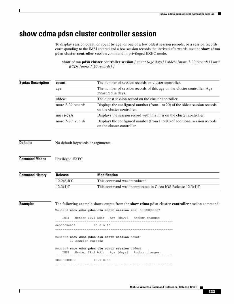
show cdma pdsn cluster controller session
show cdma pdsn cluster controller sessionTo display session count, or count by age, or one or a few oldest session records, or a session records corresponding to the IMSI entered and a few session records that arrived afterwards, use the show cdma pdsn cluster controller session command in privileged EXEC mode.
show cdma pdsn cluster controller session { count [age days] | oldest [more 1-20 records] | imsi BCDs [more 1-20 records] }
Syntax Description
Defaults No default keywords or arguments.
Command Modes Privileged EXEC
Command History
Examples The following example shows output from the show cdma pdsn cluster controller session command:
Router# show cdma pdsn clu contr session imsi 00000000007
IMSI Member IPv4 Addr Age [days] Anchor changes----------------------------------------------------------------00000000007 10.0.0.50 ----------------------------------------------------------------
Router# show cdma pdsn clu contr session count 10 session records
Router# show cdma pdsn clu contr session oldest IMSI Member IPv4 Addr Age [days] Anchor changes
----------------------------------------------------------------00000000002 10.0.0.50 ----------------------------------------------------------------
count The number of session records on cluster controller.
age The number of session records of this age on the cluster controller. Age measured in days.
oldest The oldest session record on the cluster controller.
more 1-20 records Displays the configured number (from 1 to 20) of the oldest session records on the cluster controller.
imsi BCDs Displays the session record with this imsi on the cluster controller.
more 1-20 records Displays the configured number (from 1 to 20) of additional session records on the cluster controller.
Release Modification
12.2(8)BY This command was introduced.
12.3(4)T This command was incorporated in Cisco IOS Release 12.3(4)T.
333Mobile Wireless Command Reference, Release 12.3 T

show cdma pdsn cluster controller statistics
show cdma pdsn cluster controller statisticsTo display the IP addresses of the members that registered with a specific controller, use the show cdma pdsn cluster controller statistics command in privileged EXEC mode.
show cdma pdsn cluster controller statistics
Syntax Description There are no arguments or keywords for this command.
Defaults No default keywords or arguments.
Command Modes Privileged EXEC
Command History
Examples The following example shows output from the show cdma pdsn controller statistics command:
Router# show cdma pdsn cluster controller statistics0 times did not get a buffer for a packet 0 times couldn't allocate memory 744 A11-RegReply received 0 A11-RegReply discarded, authenticaton problem 0 A11-RegReply discarded, identification problem 0 A11-RegReply discarded, unrecognized extension 975 A11-RegRequest received 0 A11-RegRequest discarded, authenticaton problem 0 A11-RegRequest discarded, identification problem 0 A11-RegRequest discarded, unrecognized application type 0 A11-RegRequest discarded, unrecognized extension 0 A11-RegRequest with unrecognized type of data 0 A11-RegRequest not sent, interface cdma-Ix not configed 744 CVSEs seek reply received 755 CVSEs seek received 4 CVSEs state ready received 4 CVSEs state admin prohibited received 0 msgs received neither A11-RegReq nor A11-RegReply 116 A10 up A11-RegReq received 96 A10 end A11-RegReq received 2 PDSN cluster membersredundancy: error: mismatch id 0 authen fail 0 ignore due to no redundancy 0 Update rcvd 0 sent 1481 orig sent 1300 fail 4 UpdateAck rcvd 1466 sent 0 DownloadReq rcvd 1 sent 4 orig sent 2 fail 0 DownloadReply rcvd 4 sent 2 orig sent 2 fail 0 drop 0 DownloadAck rcvd 2 sent 4 drop 0mwt13-6500c#
Release Modification
12.2(8)BY This command was introduced.
12.3(4)T This command was incorporated in Cisco IOS Release 12.3(4)T.
334Mobile Wireless Command Reference, Release 12.3 T

show cdma pdsn cluster member
show cdma pdsn cluster memberTo display configuration and statistics for the PDSN cluster member, use the show cdma pdsn cluster member command in privileged EXEC mode.
show cdma pdsn cluster member {configuration | statistics}
Syntax Description
Defaults No default keywords or arguments.
Command Modes Privileged EXEC
Command History
Examples The following example shows output from the show cdma pdsn cluster member command:
Router# show cdma pdsn cluster member
configuration Displays configuration information associated with the cluster member.
statistics Displays various statistics collected on cluster member signaling messages with the cluster controller.
Release Modification
12.2(8)BY This command was introduced.
12.3(4)T This command was incorporated in Cisco IOS Release 12.3(4)T.
335Mobile Wireless Command Reference, Release 12.3 T

show cdma pdsn flow
show cdma pdsn flowTo display flow-based summary of active sessions, and the flows and IP addresses assigned to the mobile numbers in each session, use the show cdma pdsn flow command in privileged EXEC mode.
show cdma pdsn flow {mn-ip-address ip_address | msid string | service-type | user string}
Syntax Description
Defaults No default keywords or arguments.
Command Modes Privileged EXEC
Command History
Examples The following example shows output from the show cdma pdsn flow command:
Router# show cdma pdsn flow
MSID NAI Type MN IP Address St100000000000099 sim1 Simple 100.4.1.1 ACT200000000000047 sim1 Simple 100.4.1.2 ACT100000000000100 sim1 Simple 100.4.1.40 ACT200000000000048 sim1 Simple 100.4.1.3 ACT100000000000101 sim1 Simple 100.4.1.5 ACT200000000000049 sim1 Simple 100.4.1.4 ACT100000000000102 sim1 Simple 100.4.1.6 ACT200000000000050 sim1 Simple 100.4.1.7 ACT100000000000103 sim1 Simple 100.4.1.9 ACT200000000000051 sim1 Simple 100.4.1.8 ACT100000000000104 sim1 Simple 100.4.1.11 ACT200000000000052 sim1 Simple 100.4.1.10 ACT100000000000105 sim1 Simple 100.4.1.12 ACT200000000000053 sim1 Simple 100.4.1.13 ACT300000000000008 sim1 Simple 100.4.1.14 ACT100000000000106 sim1 Simple 100.4.1.15 ACT200000000000054 sim1 Simple 100.4.1.16 ACT300000000000009 sim1 Simple 100.4.1.17 ACT100000000000107 sim1 Simple 100.4.1.19 ACT200000000000055 sim1 Simple 100.4.1.18 ACT100000000000122 sim1 Simple 100.4.1.21 ACT200000000000070 sim1 Simple 100.4.1.20 ACT
mn- ip-address ip_address
Specifies the IP addresses assigned to the mobile numbers in each session.
msid string Specifies the mobile subscriber id number.
service-type Specifies the service type.
user string Specifies the user.
Release Modification
12.2(8)BY This command was introduced.
12.3(4)T This command was incorporated in Cisco IOS Release 12.3(4)T.
336Mobile Wireless Command Reference, Release 12.3 T

show cdma pdsn flow
300000000000025 sim1 Simple 100.4.1.22 ACT100000000000123 sim1 Simple 100.4.1.24 ACT200000000000071 sim1 Simple 100.4.1.23 ACT300000000000026 sim1 Simple 100.4.1.25 ACT100000000000124 sim1 Simple 100.4.1.26 ACT200000000000072 sim1 Simple 100.4.1.27 ACT300000000000027 sim1 Simple 100.4.1.28 ACT100000000000125 sim1 Simple 100.4.1.29 ACT200000000000073 sim1 Simple 100.4.1.30 ACT300000000000028 sim1 Simple 100.4.1.31 ACT100000000000126 sim1 Simple 100.4.1.33 ACT200000000000074 sim1 Simple 100.4.1.32 ACT300000000000029 sim1 Simple 100.4.1.34 ACT100000000000127 sim1 Simple 100.4.1.36 ACT200000000000075 sim1 Simple 100.4.1.35 ACT300000000000030 sim1 Simple 100.4.1.37 ACT100000000000128 sim1 Simple 100.4.1.39 ACT200000000000076 sim1 Simple 100.4.1.38 ACT300000000000101 sim1 Simple 100.4.1.41 ACT100000000000199 sim1 Simple 100.4.1.43 ACT200000000000147 sim1 Simple 100.4.1.42 ACT300000000000102 sim1 Simple 100.4.1.44 ACT100000000000200 sim1 Simple 100.4.1.46 ACT --More--
337Mobile Wireless Command Reference, Release 12.3 T

show cdma pdsn pcf
show cdma pdsn pcfTo display information about PCFs that have R-P tunnels to the PDSN, use the show cdma pdsn pcf command in privileged EXEC mode.
show cdma pdsn pcf {brief | ip_addr | secure}
Syntax Description
Defaults No default behavior or values.
Command Modes Privileged EXEC
Command History
Examples The following example shows output of the show cdma pdsn pcf command with the keyword brief specified, with an IP address specified, and with the keyword secure specified:
router# show cdma pdsn pcf briefPCF IP Address Sessions Pkts In Pkts Out Bytes In Bytes Out4.0.0.1 1 14 275 23 936
Table 6 describes the fields shown in the output of the brief version of the command.
router# show cdma pdsn pcf 4.0.0.1PCF 4.0.0.1 has 1 session Received 14 pkts (275 bytes), sent 23 pkts (936 bytes)
brief Displays information about all PCFs with connected sessions.
ip_addr Displays detailed PCF information by IP address.
secure Displays the security associations for all PCFs on this PDSN.
Release Modification
12.1(3)XS This command was introduced.
12.2(2)XC The parameters of this command were changed.
12.3(4)T This command was incorporated in Cisco IOS Release 12.3(4)T.
Table 6 show cdma pdsn pcf brief Field Descriptions
Field Description
PCF IP Address IP address of the PCF.
Sessions Number of active sessions.
Pkts In Total packets received from a PCF.
Pkts Out Total packets sent to a PCF.
Bytes In Total bytes received from a PCF.
Bytes Out Total bytes sent to a PCF.
338Mobile Wireless Command Reference, Release 12.3 T

show cdma pdsn pcf
PCF Session ID 1, Mobile Station ID MIN 2000000001 A10 connection age 00:00:28 A10 registration lifetime 65535 sec, time since last registration 28 sec
Table 7 describes the fields shown in the output of the command when an IP address is specified.
Router# show cdma pdsn pcf secure Security Associations (algorithm, replay protection, key):default: spi 300, Timestamp +/- 60, key ascii foo4.0.0.1: spi 100, Timestamp +/- 60, key ascii test spi 200, Timestamp +/- 60, key ascii foo4.0.0.2: spi 100, Timestamp +/- 0, key ascii test spi 400, Timestamp +/- 0, key hex 123456789012345678901234567890124.0.0.3: spi inbound 100 outbound 200, Timestamp +/- 0, key ascii test
Table 8 describes the fields shown in the output of the command when the keyword secure is specified.
Table 7 show cdma pdsn pcf Field Descriptions
Field Description
PCF (x.x.x.x) has x session PCF address and the number of active sessions.
received x pkts (x bytes) Total packets received from a PCF.
sent x pkts (x bytes) Total packets sent to a PCF.
PCF Session ID x Session ID associated with the PCF.
Mobile Station ID MIN xxxx MIN of the mobile station initiating the session.
status Status of the IMSI session.
A10 connection age Amount of time the connection has been active.
A10 registration lifetime Duration for which the A10 registration will be active.
Table 8 show cdma pdsn pcf secure Field Descriptions
Field Description
default The default security associations (used for PCFs that do not have an explicitly configured security association).
x.x.x.x IP address of the PCF
spi spi_value Security Parameter Index, a 4-byte hex index within the security association that selects the specific security parameters to be used.
Timestamp +/- value Maximum difference allowed between the timestamp received in the A11 message and the system time on the PDSN for the A11 message to be accepted.
key {ascii|hex} key The shared secret key for the security associations
339Mobile Wireless Command Reference, Release 12.3 T

show cdma pdsn resource
show cdma pdsn resource To display AHDLC resources allocated in resource manager, use the show cdma pdsn resource command in privileged EXEC mode.
show cdma pdsn resource [slot_number [ahdlc-channel [channel_id]]]
Syntax Description
Defaults The c6500-c5 image supports 8000 sessions and the c6500-c6 image supports 20000 sessions.
Command Modes Privileged EXEC
Command History
Examples The following example shows output from the show cdma pdsn resource command:
Router# show cdma pdsn resourceResource allocated/available in the resource manager
slot 0: AHDLC Engine Type:CDMA HDLC ENGINE Engine is ENABLED total channels:16000, available channels:16000
Router#show cdma pdsn resource 0 ahdlc-channel 0 AHDLC Channel 0 State CLOSED
slot_number (Optional) Slot number of the AHDLC of interest.
ahdlc-channel [channel_id]
(Optional) Channel on the AHDLC. If no channel is specified, information for all channels is displayed.
Release Modification
12.2(2)XC This command was introduced.
12.2(8)BY The possible values for channel ID was extended to 20000.
12.3(4)T This command was incorporated in Cisco IOS Release 12.3(4)T.
340Mobile Wireless Command Reference, Release 12.3 T
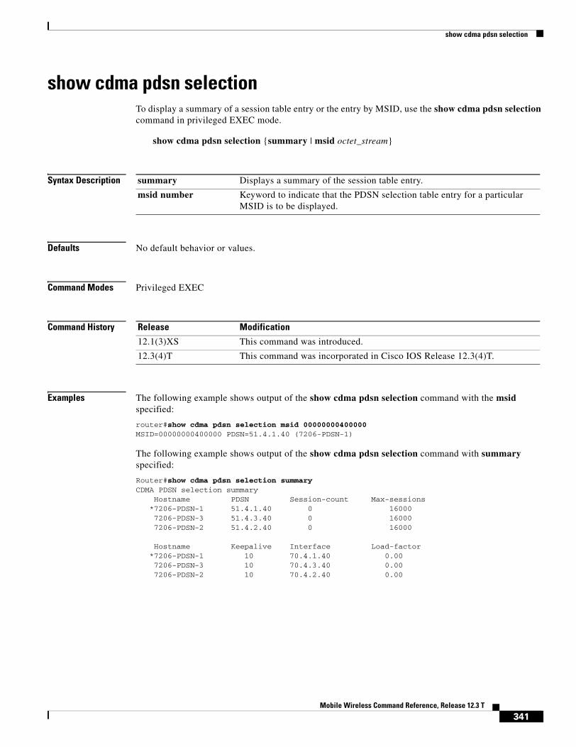
show cdma pdsn selection
show cdma pdsn selectionTo display a summary of a session table entry or the entry by MSID, use the show cdma pdsn selection command in privileged EXEC mode.
show cdma pdsn selection {summary | msid octet_stream}
Syntax Description
Defaults No default behavior or values.
Command Modes Privileged EXEC
Command History
Examples The following example shows output of the show cdma pdsn selection command with the msid specified:
router#show cdma pdsn selection msid 00000000400000MSID=00000000400000 PDSN=51.4.1.40 (7206-PDSN-1)
The following example shows output of the show cdma pdsn selection command with summary specified:
Router#show cdma pdsn selection summary CDMA PDSN selection summary
Hostname PDSN Session-count Max-sessions*7206-PDSN-1 51.4.1.40 0 160007206-PDSN-3 51.4.3.40 0 160007206-PDSN-2 51.4.2.40 0 16000
Hostname Keepalive Interface Load-factor*7206-PDSN-1 10 70.4.1.40 0.007206-PDSN-3 10 70.4.3.40 0.007206-PDSN-2 10 70.4.2.40 0.00
summary Displays a summary of the session table entry.
msid number Keyword to indicate that the PDSN selection table entry for a particular MSID is to be displayed.
Release Modification
12.1(3)XS This command was introduced.
12.3(4)T This command was incorporated in Cisco IOS Release 12.3(4)T.
341Mobile Wireless Command Reference, Release 12.3 T

show cdma pdsn session
show cdma pdsn sessionTo display the session information on the PDSN, use the show cdma pdsn session command in privileged EXEC mode.
show cdma pdsn session [brief | dormant | mn-ip-address address | msid number | user nai | prepaid]
Syntax Description
Defaults No default behavior or values.
Command Modes Privileged EXEC
Command History
Examples The following example shows output of the show cdma pdsn session command:
router# show cdma pdsn sessionMobile Station ID IMSI 111111111111111 PCF IP Address 2.2.2.100, PCF Session ID 1 A10 connection time 00:00:09, registration lifetime 65535 sec Number of A11 re-registrations 0, time since last registration 9 sec Current Access network ID 0002-0202-64 Last airlink record received is Active Start, airlink is active GRE sequence number transmit 8, receive 10 Using interface Virtual-Access1, status ACT
Using AHDLC Engine on slot 1, channel ID 2 This session has 1 flow
Flow service Proxy-Mobile, NAI [email protected] Node IP address 30.0.0.2Home Agent IP address 7.0.0.2Packets in 0, bytes in 0Packets out 0, bytes out 0 Prepaid duration 36000 secs, used 6500 secs, cumulative 13000 secs
brief (Optional) Displays a summary of all sessions.
dormant (Optional) Displays information about dormant PDSN sessions.
mn-ip-address address (Optional) Displays user information for the specified IP address.
msid number (Optional) Displays information for the specified MSID.
user nai (Optional) Displays information for the specified NAI.
prepaid (Optional) Displays information about prepaid flows.
Release Modification
12.1(3)XS This command was introduced.
12.2(2)XC The parameters of this command were altered.
12.2(8)BY The prepaid variable was introduced.
12.3(4)T This command was incorporated in Cisco IOS Release 12.3(4)T.
342Mobile Wireless Command Reference, Release 12.3 T

show cdma pdsn statistics
show cdma pdsn statisticsTo display VPDN, PPP, and RP interface statistics for the PDSN, use the show cdma pdsn selection command in privileged EXEC mode.
show cdma pdsn statistics [ rp | ppp | ahdlc 0-6 ]
Syntax Description
Defaults No default behavior or values.
Command Modes Privileged EXEC
Command History
Examples The following example shows output of the show cdma pdsn statistics command:
router# show cdma pdsn statistics RP Interface: Reg Request rcvd 23, accepted 22, denied 1, discarded 0 Initial Reg Request accepted 4, denied 0 Re-registration requests accepted 14, denied 0 De-registration accepted 4, denied 0 Error: Unspecified 23, Administratively prohibited 0 Resource unavailable 4, Authentication failed 4 Identification mismatch 2, Poorly formed requests 2 Unknown PDSN 2, Reverse tunnel mandatory 22 Reverse tunnel unavailable 1, Bad CVSE 0
Update sent 2, accepted 2, denied 0, not acked 0 Initial Update sent 2, retransmissions 0 Acknowledge received 2, discarded 0 Update reason lifetime expiry 1, PPP termination 0, other 1 Error: Unspecified 23 Administratively prohibited 0 Authentication failed 4, Identification mismatch 4 Poorly formed request 2
PPP: Current Connections 0 Connection requests 4, success 4, failure 0 Failure reason LCP 0, authentication 0, IPCP 3
rp Displays all RP interface statistics.
ppp Displays all PPP interface statistics
ahdlc 0-6 Displays all AHDLC statistics. where the range <0-6> is engine slot-id and an optional parameter. In the absence of the optional parameter, the statistics for all the engines will get displayed. The output of this command with the new option is the framing/defarming statistics of the engine.
Release Modification
12.1(3)XS This command was introduced.
12.3(4)T This command was incorporated in Cisco IOS Release 12.3(4)T.
343Mobile Wireless Command Reference, Release 12.3 T

show cdma pdsn statistics
Connection enters stage LCP 4, Auth 4, IPCP 7
Renegotiation total 0, by PDSN 0, by Mobile Node 0 Renegotiation reason LCP/IPCP 0, address mismatch 0, other 0
CHAP attempt 4, success 4, failure 0 PAP attempt 0, success 0, failure 0
MSCHAP attempt 0, success 0, failure 0 EAP attempt 0, success 0, failure 0
Release total 4, by PDSN 4, by Mobile Node 0 Release by ingress address filtering 0 Release reason: administrative 1, LCP termination 0, idle timeout 0 L2TP tunnel NOT READY YET insufficient resources 0, session timeout 0 service unavailable 0, other 0
Connection negotiated compression 0 Compression Microsoft 0, Stack 0, other 0 Connections negotiated MRRU 0, IPX 0, IP 4 Connections negotiated VJ-Compression 0, BAP 0 PPP bundles 0
VPDN Flows: A11 registration-update timeout 1 sec, retransmissions 5 Mobile IP registration timeout 5 sec A10 maximum lifetime allowed 65535 sec GRE sequencing is on Maximum PCFs limit not set Maximum sessions limit not set (default 20000 maximum) SNMP failure history table size 100 MSID Authentication is disabled Ingress address filtering is disabled Sending Agent Adv in case of IPCP Address Negotiation is disabled Aging of idle users disabled
Number of pcfs connected 1 Number of sessions connected 29, Simple IP flows 10, Mobile IP flows 9, Proxy Mobile IP flows 0, VPDN flows 10
AHDLC:
PDSN#show cdma pdsn statistics ahdlcslot 0: AHDLC Engine Type: CDMA HDLC SW ENGINE Engine is ENABLED total channels: 8000, available channels: 8000
Framing input 0 bytes, 0 paks Framing output 0 bytes, 0 paks Framing errors 0, insufficient memory 0, queue overflow 0, invalid size 0
Deframing input 0 bytes, 0 paks Defaming output 0 bytes, 0 paks Deframing errors 0, insufficient memory 0, queue overflow 0, invalid size 0, CRC errors 0
344Mobile Wireless Command Reference, Release 12.3 T

show gprs access-point
show gprs access-pointTo display information about access points on the GGSN, use the show gprs access-point command in privileged EXEC mode.
show gprs access-point {access-point-index [address-allocation] | all}
Syntax Description
Defaults No default behavior or values.
Command Modes Privileged EXEC
Command History
access-point-index Integer (from 1 to 65535) that identifies a GPRS access point. Information about that access point is shown.
access-point-index address-allocation TID and dynamically allocated mobile station (MS) addresses (by either a DHCP or RADIUS server) for PDP contexts on the specified access point are shown.
all Information about all access points on the GGSN is shown.
Release Modification
12.1(1)GA This command was introduced.
12.1(5)T This command was integrated in Cisco IOS Release 12.1(5)T.
345Mobile Wireless Command Reference, Release 12.3 T

show gprs access-point
12.2(4)MX This command was incorporated in Cisco IOS Release 12.2(4)MX.
• The following output fields were added to the display:
– accounting
– aggregate
– apn_accounting_server_group
– apn_authentication_server_group
– apn-type
– apn_username
– apn_password
– Block Roamer Mode
– GPRS vaccess interface
– VPN
– wait_accounting
• The following output fields were removed from the display:
– apn_charging_gw
– apn_backup_charging_gw
– apn_radius_server
• Several output field results were changed from binary 0 and 1 to Yes and No.
• The following output fields were added to the all version of this command:
– Access-type
– ppp-regeneration (max-session, setup-time)
– VRF Name
12.2(8)YD This command was incorporated in Cisco IOS Release 12.2(8)YD and the Block Roamer Mode output field was changed to Block Foreign-MS Mode output field.
12.2(8)YW This command was incorporated in Cisco IOS Release 12.2(8)YW.
• The following output fields were added to the display:
– input ACL
– output ACL
– backup
– RADIUS attribute suppress MSISDN
– RADIUS attribute suppress IMSI
– RADIUS attribute suppress SGSN Address
– RADIUS attribute suppress QoS
• The format of the apn_username: , apn_password: display fields was changed to apn_username: apn_password:.
Release Modification
346Mobile Wireless Command Reference, Release 12.3 T

show gprs access-point
12.2(4)MX This command was incorporated in Cisco IOS Release 12.2(4)MX.
• The following output fields were added to the display:
– accounting
– aggregate
– apn_accounting_server_group
– apn_authentication_server_group
– apn-type
– apn_username
– apn_password
– Block Roamer Mode
– GPRS vaccess interface
– VPN
– wait_accounting
• The following output fields were removed from the display:
– apn_charging_gw
– apn_backup_charging_gw
– apn_radius_server
• Several output field results were changed from binary 0 and 1 to Yes and No.
• The following output fields were added to the all version of this command:
– Access-type
– ppp-regeneration (max-session, setup-time)
– VRF Name
12.2(8)YD This command was incorporated in Cisco IOS Release 12.2(8)YD and the Block Roamer Mode output field was changed to Block Foreign-MS Mode output field.
12.2(8)YW This command was incorporated in Cisco IOS Release 12.2(8)YW.
• The following output fields were added to the display:
– input ACL
– output ACL
– backup
– RADIUS attribute suppress MSISDN
– RADIUS attribute suppress IMSI
– RADIUS attribute suppress SGSN Address
– RADIUS attribute suppress QoS
• The format of the apn_username: , apn_password: display fields was changed to apn_username: apn_password:.
Release Modification
347Mobile Wireless Command Reference, Release 12.3 T

show gprs access-point
12.2(4)MX This command was incorporated in Cisco IOS Release 12.2(4)MX.
• The following output fields were added to the display:
– accounting
– aggregate
– apn_accounting_server_group
– apn_authentication_server_group
– apn-type
– apn_username
– apn_password
– Block Roamer Mode
– GPRS vaccess interface
– VPN
– wait_accounting
• The following output fields were removed from the display:
– apn_charging_gw
– apn_backup_charging_gw
– apn_radius_server
• Several output field results were changed from binary 0 and 1 to Yes and No.
• The following output fields were added to the all version of this command:
– Access-type
– ppp-regeneration (max-session, setup-time)
– VRF Name
12.2(8)YD This command was incorporated in Cisco IOS Release 12.2(8)YD and the Block Roamer Mode output field was changed to Block Foreign-MS Mode output field.
12.2(8)YW This command was incorporated in Cisco IOS Release 12.2(8)YW.
• The following output fields were added to the display:
– input ACL
– output ACL
– backup
– RADIUS attribute suppress MSISDN
– RADIUS attribute suppress IMSI
– RADIUS attribute suppress SGSN Address
– RADIUS attribute suppress QoS
• The format of the apn_username: , apn_password: display fields was changed to apn_username: apn_password:.
Release Modification
348Mobile Wireless Command Reference, Release 12.3 T

show gprs access-point
12.2(4)MX This command was incorporated in Cisco IOS Release 12.2(4)MX.
• The following output fields were added to the display:
– accounting
– aggregate
– apn_accounting_server_group
– apn_authentication_server_group
– apn-type
– apn_username
– apn_password
– Block Roamer Mode
– GPRS vaccess interface
– VPN
– wait_accounting
• The following output fields were removed from the display:
– apn_charging_gw
– apn_backup_charging_gw
– apn_radius_server
• Several output field results were changed from binary 0 and 1 to Yes and No.
• The following output fields were added to the all version of this command:
– Access-type
– ppp-regeneration (max-session, setup-time)
– VRF Name
12.2(8)YD This command was incorporated in Cisco IOS Release 12.2(8)YD and the Block Roamer Mode output field was changed to Block Foreign-MS Mode output field.
12.2(8)YW This command was incorporated in Cisco IOS Release 12.2(8)YW.
• The following output fields were added to the display:
– input ACL
– output ACL
– backup
– RADIUS attribute suppress MSISDN
– RADIUS attribute suppress IMSI
– RADIUS attribute suppress SGSN Address
– RADIUS attribute suppress QoS
• The format of the apn_username: , apn_password: display fields was changed to apn_username: apn_password:.
Release Modification
349Mobile Wireless Command Reference, Release 12.3 T

show gprs access-point
Usage Guidelines Use the access-point-index argument to specify a particular access point number for which you want to obtain information.
Use the address-allocation keyword, to obtain information about dynamically allocated MS addresses and lease terms by access point.
Use the all keyword to obtain information about all access points in an abbreviated format.
Examples Example 1
The following is sample output of the show gprs access-point command for access-point 1:
router# show gprs access-point 1apn_index 1 apn_name = gprs.corporate.com
apn_mode: transparent apn-type: Real accounting: Disable wait_accounting: Disable
input ACL: None, output ACL: None dynamic_address_pool: dhcp-proxy-client apn_dhcp_server: 10.99.100.5 backup: 10.99.100.4 apn_dhcp_gateway_addr: 10.27.1.1 apn_authentication_server_group: foo apn_accounting_server_group: foo1 apn_username: apn_password: subscribe_required: No deactivate_pdp_context_on violation: Yes network_activation_allowed: Yes Block Foreign-MS Mode: Disable VPN: Disable (VRF Name : None)
GPRS vaccess interface: Virtual-Access2RADIUS attribute suppress MSISDN: DisabledRADIUS attribute suppress IMSI: DisabledRADIUS attribute suppress SGSN Address: DisabledRADIUS attribute suppress QoS
number of ip_address_allocated 0idle timer: 0Security featuresVerify mobile source addr: enableVerify mobile destination addr: enable
Traffic redirection:Mobile-to-mobile: destination 1.1.1.1
Total number of PDP in this APN :0
aggregate: In APN: Disable
In Global: Disable
The following table describes the fields show in the display.
12.3(2)XB This command was incorporated in Cisco IOS Release 12.3(2)XB.
12.3(4)T The changes introduced in Cisco IOS Release 12.2(4)MX, 12.2(8)YD, and 12.2(8)YW were incorporated in Cisco IOS Release 12.3(4)T.
Release Modification
350Mobile Wireless Command Reference, Release 12.3 T

show gprs access-point
Field Description
accounting Current status of accounting services at the APN:
• Enable—Accounting services are enabled at the APN. This is the default for non-transparent access APNs.
• Disable—Accounting services are disabled at the APN. This is the default for transparent access APNs.
You can configure an APN for accounting services using the aaa-accounting access-point configuration command.
aggregate Route aggregation configuration information on the GGSN.
The output display includes the “In APN” field for configuration information for the access point, and the “In global” field for global configuration on the GGSN.
The output field may contain the following information:
• IP network address and mask for which PDP requests on the access point will be collectively routed over the virtual template interface on the GGSN. IP address and mask information appears if an aggregate range has been configured on the GGSN.
• auto—Indicates that the GGSN uses the allocated IP mask from the DHCP or RADIUS server to perform route aggregation on the APN. This keyword appears when the APN has been configured with the aggregate auto access-point configuration command. This value only applies to the APN.
• Disable—Indicates that route aggregation is not configured at either the APN or global level.
apn_accounting_server_group Name of the AAA server group providing accounting services.
apn_authentication_server_group Name of the AAA server group providing authentication services.
apn_dhcp_gateway_addr IP address of the DHCP gateway, if configured.
apn_dhcp_server IP address of the DHCP server, if configured.
apn_index Number assigned to this access point.
apn_mode Current setting for the access-mode command:
• Transparent—Users are allowed access without authorization or authentication.
• Non-transparent—Users must be authenticated by the GGSN acting as a proxy for the authentication.
apn_name Access point name.
apn-type Current setting for the access-type command:
• Real—APN type that corresponds to a physical interface to an external network on the GGSN.
• Virtual—APN type that is not associated with any specific physical target network.
351Mobile Wireless Command Reference, Release 12.3 T
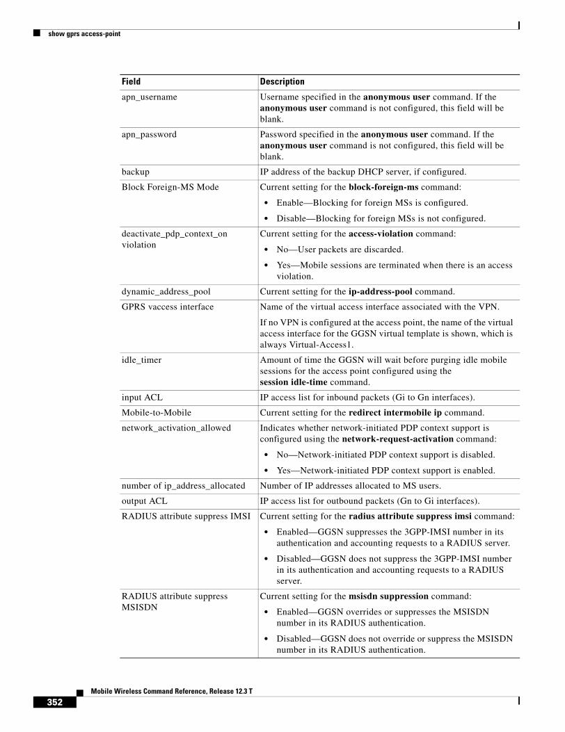
show gprs access-point
apn_username Username specified in the anonymous user command. If the anonymous user command is not configured, this field will be blank.
apn_password Password specified in the anonymous user command. If the anonymous user command is not configured, this field will be blank.
backup IP address of the backup DHCP server, if configured.
Block Foreign-MS Mode Current setting for the block-foreign-ms command:
• Enable—Blocking for foreign MSs is configured.
• Disable—Blocking for foreign MSs is not configured.
deactivate_pdp_context_on violation
Current setting for the access-violation command:
• No—User packets are discarded.
• Yes—Mobile sessions are terminated when there is an access violation.
dynamic_address_pool Current setting for the ip-address-pool command.
GPRS vaccess interface Name of the virtual access interface associated with the VPN.
If no VPN is configured at the access point, the name of the virtual access interface for the GGSN virtual template is shown, which is always Virtual-Access1.
idle_timer Amount of time the GGSN will wait before purging idle mobile sessions for the access point configured using the session idle-time command.
input ACL IP access list for inbound packets (Gi to Gn interfaces).
Mobile-to-Mobile Current setting for the redirect intermobile ip command.
network_activation_allowed Indicates whether network-initiated PDP context support is configured using the network-request-activation command:
• No—Network-initiated PDP context support is disabled.
• Yes—Network-initiated PDP context support is enabled.
number of ip_address_allocated Number of IP addresses allocated to MS users.
output ACL IP access list for outbound packets (Gn to Gi interfaces).
RADIUS attribute suppress IMSI Current setting for the radius attribute suppress imsi command:
• Enabled—GGSN suppresses the 3GPP-IMSI number in its authentication and accounting requests to a RADIUS server.
• Disabled—GGSN does not suppress the 3GPP-IMSI number in its authentication and accounting requests to a RADIUS server.
RADIUS attribute suppress MSISDN
Current setting for the msisdn suppression command:
• Enabled—GGSN overrides or suppresses the MSISDN number in its RADIUS authentication.
• Disabled—GGSN does not override or suppress the MSISDN number in its RADIUS authentication.
Field Description
352Mobile Wireless Command Reference, Release 12.3 T

show gprs access-point
RADIUS attribute suppress SGSN Address
Current setting for the radius attribute suppress sgsn-address command:
• Enabled—GGSN suppresses the 3GPP VSA 3GPP-SGSN-Address subattribute in its RADIUS authentication and accounting requests.
• Disabled—GGSN does not suppress the 3GPP VSA 3GPP-SGSN-Address subattribute in its RADIUS authentication and accounting requests.
RADIUS attribute suppress QoS Current setting for the radius attribute suppress qos command:
• Enabled—GGSN suppresses the 3GPP VSA 3GPP-QoS-Profile subattribute in its RADIUS authentication and accounting requests.
• Disabled—GGSN does not suppress the 3GPP VSA 3GPP-QoS-Profile subattribute in its RADIUS authentication and accounting requests.
subscribe_required Current setting for the subscription-required command:
• No—No subscription is required.
• Yes—Subscription is required for access point users. The GGSN looks for the “subscription verified” selection mode in the PDP context request to establish the session.
Total number of PDP in this APN Number of active PDP contexts for this access point.
Verify mobile source addr Current setting for the security verify source command:
• Enabled—GGSN verifies the source IP address of upstream TPDUs against addresses previously assigned to MSs.
• Disabled—GGSN does not verify the source IP address of upstream TPDUs against addresses previously assigned to MSs.
Verify mobile destination addr Current setting for the security verify destination command:
• Enabled—GGSN verifies the destination address of upstream TPDUs against the global list of PLMN addresses specified using the gprs plmn ip address command.
• Disabled—GGSN does not verify the destination address of upstream TPDUs against the global list of PLMN addresses specified using the gprs plmn ip address command.
VPN Indicates whether a Virtual Private Network (VPN) is enabled or disabled at the access point.
Field Description
353Mobile Wireless Command Reference, Release 12.3 T

show gprs access-point
Example 2
The following is sample output of the show gprs access-point address-allocation command:
router# show gprs access-point 8 address-allocation
TID PDP_ADDRESS
1111111100000099 10.88.105.227 1111111100000191 10.88.105.7 1111111100000192 10.88.105.70 1111111100000297 10.88.106.162 1111111100000298 10.88.106.169 1111111100000299 10.88.106.161 1111111100000391 10.88.106.150 1111111100000392 10.88.106.25 1111111100000442 10.88.106.196 1111111100000443 10.88.106.197 1111111100000886 10.88.108.153 1111111100000887 10.88.108.158 2222222200000000 10.88.111.255
The following table describes the fields show in the display.
Example 3
The following is sample output of the show gprs access-point all command:
router# show gprs access-point all
There are 3 Access-Points configured
Index Mode Access-type AccessPointName VRF Name
VRF name Name assigned to the VPN Routing and Forwarding instance. A value of None appears when VRF is not enabled at the access point.
wait_accounting Current status of RADIUS accounting response message waiting at the APN:
• Enable—GGSN waits for an accounting response message from the RADIUS server before sending an activate PDP context request to the SGSN.
• Disable—GGSN sends an activate PDP context request to the SGSN after sending an accounting request to the RADIUS server. The GGSN does not wait for a RADIUS accounting response.
You can configure RADIUS accounting response message waiting using the gprs gtp response-message wait-accounting global configuration command, or the response-message wait-accounting access-point configuration command.
Field Description
Field Description
TID Tunnel ID for the PDP context request on the APN.
PDP_ADDRESS IP address assigned to the PDP context request on the APN.
354Mobile Wireless Command Reference, Release 12.3 T

show gprs access-point
-----------------------------------------------------------------------1 transparent Real corporate_1.com corporate_1.com
ppp-regeneration (max-session: 10000, setup-time: 60)-----------------------------------------------------------------------2 non-transparent Real corporate_2.com-----------------------------------------------------------------------3 transparent Virtual corporate_3.com-----------------------------------------------------------------------
The following table describes the fields show in the display.
Related Commands
Field Description
Index Integer assigned to the access point in the GGSN configuration. The index number is used to reference an APN in GGSN commands.
Mode Authorization configured on the access point. The possible values are:
• transparent—Users who access the PDN through the access point associated with the current virtual template are allowed access without authorization or authentication.
• non-transparent—Users who access the PDN through the current virtual template must be authenticated by the GGSN acting as a proxy for the authentication.
Access-type Type of access point. The possible values are:
• Real—APN type that corresponds to an external physical network on the GGSN. This is the default value.
• Virtual—APN type that is not associated with any specific physical target network on the GGSN. Virtual APNs are used to simply HLR provisioning in the PLMN.
AccessPointName Access point network ID, which is commonly an Internet domain name.
ppp-regeneration (max-session, setup-time)
PPP regeneration session parameters configured at the access point:
• max-session—Maximum number of PPP regenerated sessions allowed at the access point.
• setup-time—Maximum amount of time (between 1 and 65535 seconds) within which a PPP regenerated session must be established.
VRF Name Name of the VPN routing and forwarding instance associated with the APN.
Command Description
access-point Specifies an access point number and enters access-point configuration mode.
355Mobile Wireless Command Reference, Release 12.3 T
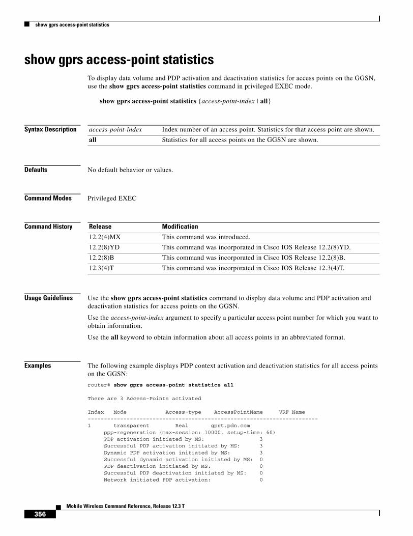
show gprs access-point statistics
show gprs access-point statisticsTo display data volume and PDP activation and deactivation statistics for access points on the GGSN, use the show gprs access-point statistics command in privileged EXEC mode.
show gprs access-point statistics {access-point-index | all}
Syntax Description
Defaults No default behavior or values.
Command Modes Privileged EXEC
Command History
Usage Guidelines Use the show gprs access-point statistics command to display data volume and PDP activation and deactivation statistics for access points on the GGSN.
Use the access-point-index argument to specify a particular access point number for which you want to obtain information.
Use the all keyword to obtain information about all access points in an abbreviated format.
Examples The following example displays PDP context activation and deactivation statistics for all access points on the GGSN:
router# show gprs access-point statistics all
There are 3 Access-Points activated
Index Mode Access-type AccessPointName VRF Name-----------------------------------------------------------------------1 transparent Real gprt.pdn.com
ppp-regeneration (max-session: 10000, setup-time: 60)PDP activation initiated by MS: 3
Successful PDP activation initiated by MS: 3 Dynamic PDP activation initiated by MS: 3 Successful dynamic activation initiated by MS: 0 PDP deactivation initiated by MS: 0 Successful PDP deactivation initiated by MS: 0 Network initiated PDP activation: 0
access-point-index Index number of an access point. Statistics for that access point are shown.
all Statistics for all access points on the GGSN are shown.
Release Modification
12.2(4)MX This command was introduced.
12.2(8)YD This command was incorporated in Cisco IOS Release 12.2(8)YD.
12.2(8)B This command was incorporated in Cisco IOS Release 12.2(8)B.
12.3(4)T This command was incorporated in Cisco IOS Release 12.3(4)T.
356Mobile Wireless Command Reference, Release 12.3 T

show gprs access-point statistics
Successful network initiated PDP activation: 0 PDP deactivation initiated by GGSN: 1 Successful PDP deactivation initiated by GGSN: 1 active PDP: 3 upstream data volume in octets: 0 downstream data volume in octets: 0----------------------------------------------------------4 transparent gprs.pdn.com
PDP activation initiated by MS: 1 Successful PDP activation initiated by MS: 1 Dynamic PDP activation initiated by MS: 0 Successful dynamic activation initiated by MS: 0 PDP deactivation initiated by MS: 0 Successful PDP deactivation initiated by MS: 0 Network initiated PDP activation: 0 Successful network initiated PDP activation: 0 PDP deactivation initiated by GGSN: 6 Successful PDP deactivation initiated by GGSN: 6 active PDP: 0 upstream data volume in octets: 0 downstream data volume in octets: 0----------------------------------------------------------5 transparent gpru.pdn.com
PDP activation initiated by MS: 1 Successful PDP activation initiated by MS: 1 Dynamic PDP activation initiated by MS: 0 Successful dynamic activation initiated by MS: 0 PDP deactivation initiated by MS: 0 Successful PDP deactivation initiated by MS: 0 Network initiated PDP activation: 0 Successful network initiated PDP activation: 0 PDP deactivation initiated by GGSN: 0 Successful PDP deactivation initiated by GGSN: 6 active PDP: 0 upstream data volume in octets: 0 downstream data volume in octets: 0
Table 9 describes the fields shown in the display:
Table 9 show gprs access-point statistics Field Descriptions
Field Description
active PDP Number of PDP contexts that are currently established on the GGSN.
downstream data volume in octets
Number of bytes of data received by the GGSN from the PDN, or network.
Dynamic PDP activation initiated by MS
Number of Create PDP Context Request messages received by the GGSN from an MS without a PDP address. (Duplicate requests are not counted.)
Network initiated PDP activation
Number of Create PDP Context Request messages received by the GGSN from network initiation.
PDP activation initiated by MS Number of Create PDP Context Request messages received by the GGSN from an SGSN. (Duplicate requests are not counted.)
PDP deactivation initiated by GGSN
Number of Delete PDP Context Request messages sent by the GGSN to an SGSN.
PDP deactivation initiated by MS
Number of Delete PDP Context Request messages received by the GGSN from an SGSN. (Duplicate messages are not counted.)
357Mobile Wireless Command Reference, Release 12.3 T

show gprs access-point statistics
Related Commands
ppp-regeneration (max-session, setup-time)
PPP regeneration session parameters configured at the access point:
• max-session—Maximum number of PPP regenerated sessions allowed at the access point.
• setup-time—Maximum amount of time (between 1 and 65535 seconds) within which a PPP regenerated session must be established.
Successful dynamic activation initiated by MS
Number of Create PDP Context Response messages sent by the GGSN with a cause value of “GTP_RES_REQACCEPTED”, indicating that the PDP address has been dynamically assigned.
Successful network initiated PDP activation
Number of PDP contexts activated on the GGSN that were initiated by the network.
Successful PDP activation initiated by MS
Number of Create PDP Context Response messages sent by the GGSN with a cause value of “GTP_RES_REQACCEPTED.”
Successful PDP deactivation initiated by GGSN
Number of Delete PDP Context Response messages received by the GGSN from an SGSN.
Successful PDP deactivation initiated by MS
Number of Delete PDP Context Response messages sent by the GGSN to an SGSN with a cause value of “GTP_RES_REQACCEPTED”.
upstream data volume in octets Number of bytes of data received by the GGSN from the SGSN.
Table 9 show gprs access-point statistics Field Descriptions (continued)
Field Description
Command Description
clear gprs access-point statistics
Clears statistics counters for a specific access point or for all access points on the GGSN.
show gprs access-point Displays information about access points on the GGSN.
358Mobile Wireless Command Reference, Release 12.3 T

show gprs charging parameters
show gprs charging parameters To display information about the current GPRS charging configuration, use the show gprs charging parameters command in privileged EXEC mode.
show gprs charging parameters
Syntax Description This command has no arguments or keywords.
Defaults No default behavior or values.
Command Modes Privileged EXEC
Command History Release Modification
12.1(1)GA This command was introduced.
12.1(5)T This command was integrated in Cisco IOS Release 12.1(5)T.
12.2(4)MX This command was incorporated in Cisco IOS Release 12.2(4)MX.
The following output fields were added to the display:
• Charging CDR Option Local Record Sequence Number
• Charging CDR Option No Partial CDR Generation
• Charging CDR Option Node ID
• Charging CDR Option Packet Count
• Charging Change Condition Limit
• Charging Send Buffer Size
• Charging GTP’ Port Number
• Charging MCC Code
• Charging MNC Code
• Charging Roamers CDR Only
• Charging HPLMN Matching Criteria
• Charging SGSN Limit
The following output fields were removed from the display:
• Charging MCC Code
• Charging MNC Code
• Charging HPLMN Matching Criteria
12.2(8)YD This command was incorporated in Cisco IOS Release 12.2(8)YD.
359Mobile Wireless Command Reference, Release 12.3 T

show gprs charging parameters
Usage Guidelines Use the show gprs charging parameters command to display the currently active charging parameters for the GGSN.
Examples The following is sample output of the show gprs charging parameters command:
router# show gprs charging parameters
GPRS Charging Protocol Parameters =================================
* Default Charging Gateway Address: <9.9.9.9>* Default Backup Charging Gateway Address:UNDEFINED.* Current Active Charging Gateway Address:<9.9.9.9>* Current Backup Charging Gateway Address:UNDEFINED.* Charging Server Switch-Over Timer: <15> seconds.* Charging Path Protocol: tcp* GTP' use short header: DISABLED* Charging Message Options: Transfer Request: - Packet Transfer Command IE: ENABLED. Transfer Response: - Number Responded: DISABLED.* Charging MAP DATA TOS: <3>* Charging Transfer Interval: <105> seconds.* Charging Transfer Threshold: <400> bytes.* Charging CDR Aggregation Limit: <255> CDRs per msg.* Charging Packet Queue Size: <128> messages.* Charging Gateway Path Request Timer: <1> Minutes.* Charging Change Condition Limit: <5>* Charging SGSN Limit: DISABLED.* Charging Time Limit: <3000>* Charging Send Buffer Size: <1460>* Charging Port Number: <3386>* Charging Roamers CDR Only: DISABLED.* Charging CDR Option: - Local Record Sequence Number: DISABLED. - APN Selection Mode: DISABLED. - No Partial CDR Generation: DISABLED.
12.2(8)YW This command was incorporated in the Cisco IOS Release 12.2(8)YW.
• The Charging Path Protocol field was changed from binary 0 and 1 to udp and tcp.
• The Charging qos-info output field was changed to Charging release.
• The following output fields were added to the display:
– Charging Time Limit
– Charging qos-info
– Charging Transfer Format.
– GTP’ use short header
12.3(2)XB This command was incorporated in Cisco IOS Release 12.3(2)XB.
12.3(4)T The changes introduced in Cisco IOS Release 12.2(4)MX and 12.2(8)YW were incorporated in Cisco IOS Release 12.3(4)T.
Release Modification
360Mobile Wireless Command Reference, Release 12.3 T

show gprs charging parameters
- Node ID: DISABLED. - Packet Count: DISABLED. - Served MSISDN: DISABLED. - Private Echo: DISABLED.* Charging release: 99* Charging Tariff Time Changes: - Tariff Time Change (#0): 04:04:01 - Tariff Time Change (#1): 17:00:00 - Tariff Time Change (#2): 21:25:00
Table 10 describes the fields shown in the display.
Table 10 show gprs charging parameters Field Descriptions
Field Description
Charging CDR Aggregation Limit Maximum number of CDRs that the GGSN aggregates in a charging data transfer message to the charging gateway.
You can configure this limit using the gprs charging cdr-aggregation-limit command.
Charging CDR Option: Local Record Sequence Number
Status indicating if the GGSN uses the local record sequence field in G-CDRs. The possible values are enabled or disabled.
You can enable the GGSN to use the local record sequence field in G-CDRs using the gprs charging cdr-option local-record-sequence-number command.
Charging CDR Option: APN Selection Mode
Status indicating if the GGSN provides the reason code for APN selection in G-CDRs. The possible values are enabled or disabled.
You can enable the GGSN to provide the APN selection mode in G-CDRs using the gprs charging cdr-option apn-selection-mode command.
Charging CDR Option: No Partial CDR Generation
Status indicating if the GGSN can create partial CDRs. The possible values are enabled or disabled.
You can disable partial CDR generation by the GGSN using the gprs charging cdr-option no-partial-cdr-generation command.
Charging CDR Option: Node ID Status indicating if the GGSN specifies the name of the node that generated the CDR in the node ID field of the G-CDR. The possible values are enabled or disabled.
You can enable the GGSN to use the node ID field in G-CDRs using the gprs charging cdr-option node-id command.
Charging CDR Option: Packet Count Status indicating if the GGSN provides uplink and downlink packet counts in the optional record extension field of a G-CDR. The possible values are ON or OFF.
You can enable the GGSN to provide packet counts using the gprs charging cdr-option packet-count command.
361Mobile Wireless Command Reference, Release 12.3 T
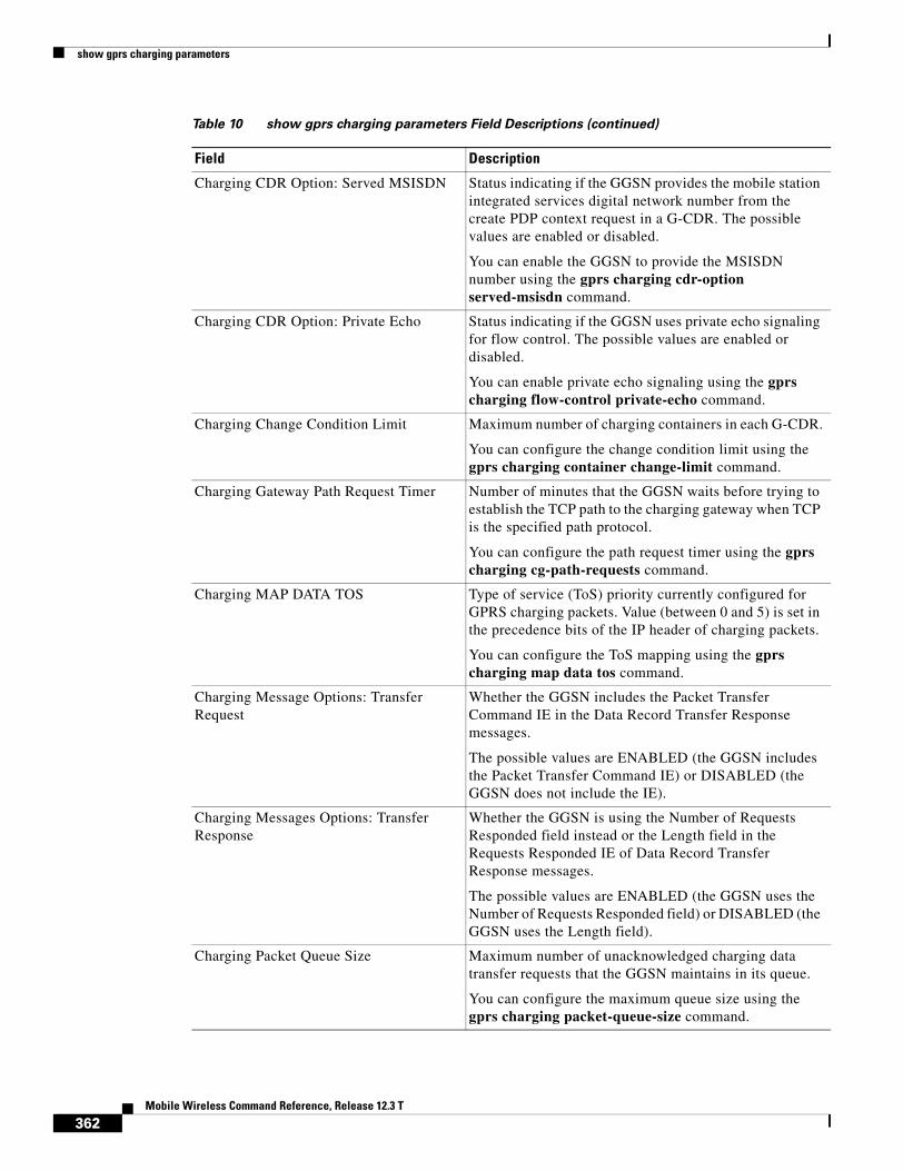
show gprs charging parameters
Charging CDR Option: Served MSISDN Status indicating if the GGSN provides the mobile station integrated services digital network number from the create PDP context request in a G-CDR. The possible values are enabled or disabled.
You can enable the GGSN to provide the MSISDN number using the gprs charging cdr-option served-msisdn command.
Charging CDR Option: Private Echo Status indicating if the GGSN uses private echo signaling for flow control. The possible values are enabled or disabled.
You can enable private echo signaling using the gprs charging flow-control private-echo command.
Charging Change Condition Limit Maximum number of charging containers in each G-CDR.
You can configure the change condition limit using the gprs charging container change-limit command.
Charging Gateway Path Request Timer Number of minutes that the GGSN waits before trying to establish the TCP path to the charging gateway when TCP is the specified path protocol.
You can configure the path request timer using the gprs charging cg-path-requests command.
Charging MAP DATA TOS Type of service (ToS) priority currently configured for GPRS charging packets. Value (between 0 and 5) is set in the precedence bits of the IP header of charging packets.
You can configure the ToS mapping using the gprs charging map data tos command.
Charging Message Options: Transfer Request
Whether the GGSN includes the Packet Transfer Command IE in the Data Record Transfer Response messages.
The possible values are ENABLED (the GGSN includes the Packet Transfer Command IE) or DISABLED (the GGSN does not include the IE).
Charging Messages Options: Transfer Response
Whether the GGSN is using the Number of Requests Responded field instead or the Length field in the Requests Responded IE of Data Record Transfer Response messages.
The possible values are ENABLED (the GGSN uses the Number of Requests Responded field) or DISABLED (the GGSN uses the Length field).
Charging Packet Queue Size Maximum number of unacknowledged charging data transfer requests that the GGSN maintains in its queue.
You can configure the maximum queue size using the gprs charging packet-queue-size command.
Table 10 show gprs charging parameters Field Descriptions (continued)
Field Description
362Mobile Wireless Command Reference, Release 12.3 T

show gprs charging parameters
Charging Path Protocol Protocol in use between the GGSN and the charging gateway. The possible values are udp or tcp.
You can configure the charging path protocol using the gprs charging path-protocol command.
Charging Port Number Destination port of the charging gateway.
You can configure the destination port using the gprs charging port command.
Charging release Whether UMTS (R99) and GSM (R97/R98) QoS profile formats are presented in G-CDRs. The possible values are 99 (GSM and UMTS QoS profile formats are presented) or 98 (only GSM QoS profile formats are presented).
You can configure the type of QoS profile format to be included using the gprs charging release command.
Charging Roamers CDR Only Status of the charging for roamers feature on the GGSN. The possible values are enabled or disabled.
You can configure the GGSN to support creation of CDRs for roaming subscribers using the gprs charging roamers command.
Charging Send Buffer Size Size (in bytes) of the buffer that contains the GTP’ PDU and signaling messages on the GGSN.
You can configure the buffer size using the gprs charging send-buffer command.
Charging Server Switch-Over Timer Amount of time (in seconds) that the GGSN waits before sending charging data to the backup charging gateway, after the active charging gateway fails.
You can configure this period of time using the gprs charging server-switch-timer command.
Charging SGSN Limit Maximum number of SGSN changes that can occur before the GGSN closes a G-CDR for a particular PDP context.
Charging Tariff Time Changes Time of day when GPRS charging tariffs change.
You can configure this time using the gprs charging tariff-time command.
Charging Transfer Interval Amount of time (in seconds) that the GGSN waits before checking and sending any closed CDRs to the charging gateway.
You can configure this period of time using the gprs charging transfer interval command.
Table 10 show gprs charging parameters Field Descriptions (continued)
Field Description
363Mobile Wireless Command Reference, Release 12.3 T

show gprs charging parameters
Related Commands
Charging Transfer Threshold Maximum size (in bytes) that the GGSN maintains in a charging container before closing it and updating the CDR.
You can configure the container volume using the gprs charging container volume-threshold command.
Current Active Charging Gateway Address IP address of the charging gateway to which the GGSN is currently sending charging data.
You can configure the primary charging gateway using the gprs default charging-gateway command.
Current Backup Charging Gateway Address
IP address of the backup charging gateway to which the GGSN will send charging data if the current active charging gateway becomes unavailable.
You can configure the backup charging gateway using the gprs default charging-gateway command.
Default Backup Charging Gateway Address
IP address of the default secondary, or backup, charging gateway.
You can configure the default backup charging gateway using the gprs default charging-gateway command.
Default Charging Gateway Address IP address of the default primary charging gateway.
You can configure the default primary charging gateway using the gprs default charging-gateway command.
GTP’ use short header Whether the GGSN is using the GTP short header (6-byte header). The possible values are ENABLED (the GGSN is using the GTP short header) or DISABLED (the GGSN is using the GTP long header).
You can configure the GGSN to use the GTP short header using the gprs charging header short command.
Table 10 show gprs charging parameters Field Descriptions (continued)
Field Description
Command Description
show gprs charging statistics
Displays cumulative charging statistics for the GGSN.
364Mobile Wireless Command Reference, Release 12.3 T

show gprs charging statistics
show gprs charging statisticsTo display cumulative charging statistics for the GGSN, use the show gprs charging statistics privileged EXEC command.
show gprs charging statistics
Syntax Description This command has no arguments or keywords.
Defaults No default behavior or values.
Command Modes Privileged EXEC
Command History
Usage Guidelines Use the show gprs charging statistics command to display cumulative charging statistics since the last restart of the GGSN.
Examples The following is sample output of the show gprs charging statistics command:
router# show gprs charging statistics allGPRS Charging Protocol Statistics=================================
* Total Number of CDRs for Charging: <200>* Total Number of Containers for Charging: <104>* Total Number of CDR_Output_Msgs sent: <22>
-- Charging Gateway Statistics --* Charging Gateway Down Count: <1>* Last Charging Gateway Down Time = 2001/11/29 15:23:0
Table 11 describes the fields shown in the display.
Release Modification
12.1(1)GA This command was introduced.
12.1(5)T This command was integrated in Cisco IOS Release 12.1(5)T.
12.2(4)MX This command was incorporated in Cisco IOS Release 12.2(4)MX, and the statistics were changed to be cumulative since the last restart of the GGSN and the keyword options were removed.
12.2(8)YD This command was incorporated in Cisco IOS Release 12.2(8)YD.
12.2(8)B This command was incorporated in Cisco IOS Release 12.2(8)B.
12.3(4)T This command was incorporated in Cisco IOS Release 12.3(4)T.
12.3(8)T This command was incorporated in Cisco IOS Release 12.3(8)T.
365Mobile Wireless Command Reference, Release 12.3 T

show gprs charging statistics
.
Related Commands
Table 11 show gprs charging statistics Field Descriptions
Field Description
Total Number of CDRs for Charging Cumulative number of open and closed G-CDRs on the GGSN since the last startup of the GGSN.
Total Number of Containers for Charging Cumulative number of all open and closed charging containers for all G-CDRs on the GGSN since the last startup of the GGSN.
Total Number of CDR_Output_Msgs sent Cumulative number of G-CDR output messages that the GGSN sent to the charging gateway and received acknowledgment for since the last startup of the GGSN.
Charging Gateway Down Count Number of times that the charging gateway has transitioned its state (from up or unknown, to down) since the last startup of the GGSN.
Last Charging Gateway Down Time Recorded system time when the charging gateway was last in a down state. This statistics only appears if a charging gateway has been down.
Command Description
show gprs charging parameters
Displays information about the current GPRS charging configuration.
show gprs charging status
Displays current statistics about the transfer of charging packets between the GGSN and charging gateways.
366Mobile Wireless Command Reference, Release 12.3 T
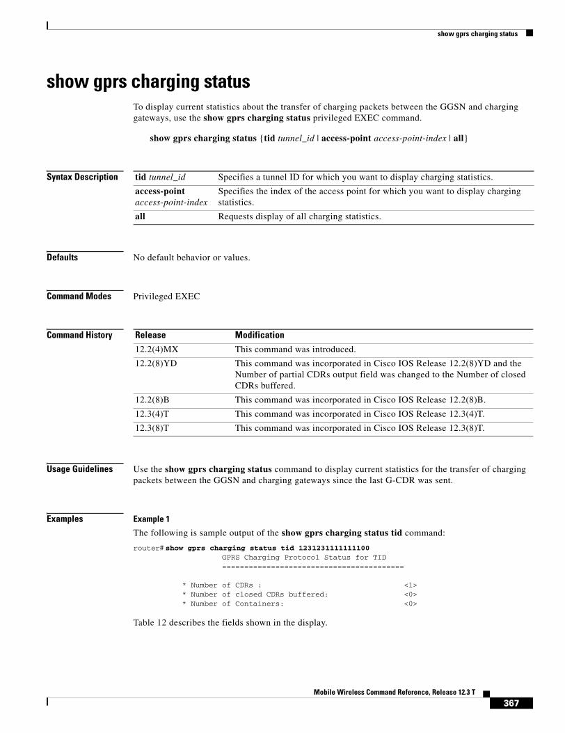
show gprs charging status
show gprs charging statusTo display current statistics about the transfer of charging packets between the GGSN and charging gateways, use the show gprs charging status privileged EXEC command.
show gprs charging status {tid tunnel_id | access-point access-point-index | all}
Syntax Description
Defaults No default behavior or values.
Command Modes Privileged EXEC
Command History
Usage Guidelines Use the show gprs charging status command to display current statistics for the transfer of charging packets between the GGSN and charging gateways since the last G-CDR was sent.
Examples Example 1
The following is sample output of the show gprs charging status tid command:
router# show gprs charging status tid 1231231111111100GPRS Charging Protocol Status for TID=========================================
* Number of CDRs : <1>* Number of closed CDRs buffered: <0>* Number of Containers: <0>
Table 12 describes the fields shown in the display.
tid tunnel_id Specifies a tunnel ID for which you want to display charging statistics.
access-point access-point-index
Specifies the index of the access point for which you want to display charging statistics.
all Requests display of all charging statistics.
Release Modification
12.2(4)MX This command was introduced.
12.2(8)YD This command was incorporated in Cisco IOS Release 12.2(8)YD and the Number of partial CDRs output field was changed to the Number of closed CDRs buffered.
12.2(8)B This command was incorporated in Cisco IOS Release 12.2(8)B.
12.3(4)T This command was incorporated in Cisco IOS Release 12.3(4)T.
12.3(8)T This command was incorporated in Cisco IOS Release 12.3(8)T.
367Mobile Wireless Command Reference, Release 12.3 T

show gprs charging status
Example 2
The following is sample output of the show gprs charging status access-point command:
router# show gprs charging status access-point 1
GPRS Charging Protocol Status for APN=========================================
* Number of CDRs: <96>* Number of closed CDRs buffered: <0>* Number of Containers: <0>
Table 13 describes the fields shown in the display.
Example 3
The following is sample output of the show gprs charging status all command:
router# show gprs charging status allGPRS Charging Protocol Status=================================
* Number of APNs : <1>* Number of CDRs : <96>* Number of closed CDRs buffered: <0>* Number of Containers buffered: <0>* Number of pending unack. CDR_Output_Msgs: <1>
Table 14 describes the fields shown in the display.
Table 12 show gprs charging status tid Field Descriptions
Field Description
Number of CDRs Number of currently open and closed G-CDRs on the GGSN for the specified TID, since the last G-CDR was successfully sent to the charging gateway.
Number of closed CDRs buffered Number of currently closed G-CDRs that the GGSN has not yet sent to the charging gateway for the specified TID.
Number of Containers Number of all currently open and closed charging containers for the specified TID, since the last G-CDR was successfully sent to the charging gateway.
Table 13 show gprs charging status access-point Field Descriptions
Field Description
Number of CDRs Number of currently open and closed G-CDRs on the GGSN for the specified access point, since the last G-CDR was successfully sent to the charging gateway.
Number of closed CDRs buffered Number of currently closed G-CDRs that the GGSN has not yet sent to the charging gateway for the specified access point.
Number of Containers Number of all currently open and closed charging containers for the specified access point, since the last G-CDR was successfully sent to the charging gateway.
368Mobile Wireless Command Reference, Release 12.3 T

show gprs charging status
Related Commands
Table 14 show gprs charging status Field Descriptions
Field Description
Number of APNs Number of access points for which charging data has currently been collected. This statistic appears in the all version of this command only.
Number of CDRs Number of currently open and closed G-CDRs on the GGSN since the last G-CDR was successfully sent to the charging gateway. For the tid and access-point versions of this command, this is the number of currently open and closed G-CDRs for the specified TID or access point.
Number of closed CDRs buffered Number of currently closed G-CDRs that the GGSN has not yet sent to the charging gateway. For the tid and access-point versions of this command, this is the number of currently closed G-CDRs for the specified TID or access-point that have not yet been sent to the charging gateway.
Number of Containers buffered Number of all currently open and closed charging containers since the last G-CDR was successfully sent to the charging gateway.
Number of pending unack. CDR_Output_Msgs
Number of G-CDR output messages sent by the GGSN that are not acknowledged by the charging gateway.
Command Description
show gprs charging parameters
Displays information about the current GPRS charging configuration.
show gprs charging statistics
Displays cumulative charging statistics for the GGSN.
369Mobile Wireless Command Reference, Release 12.3 T
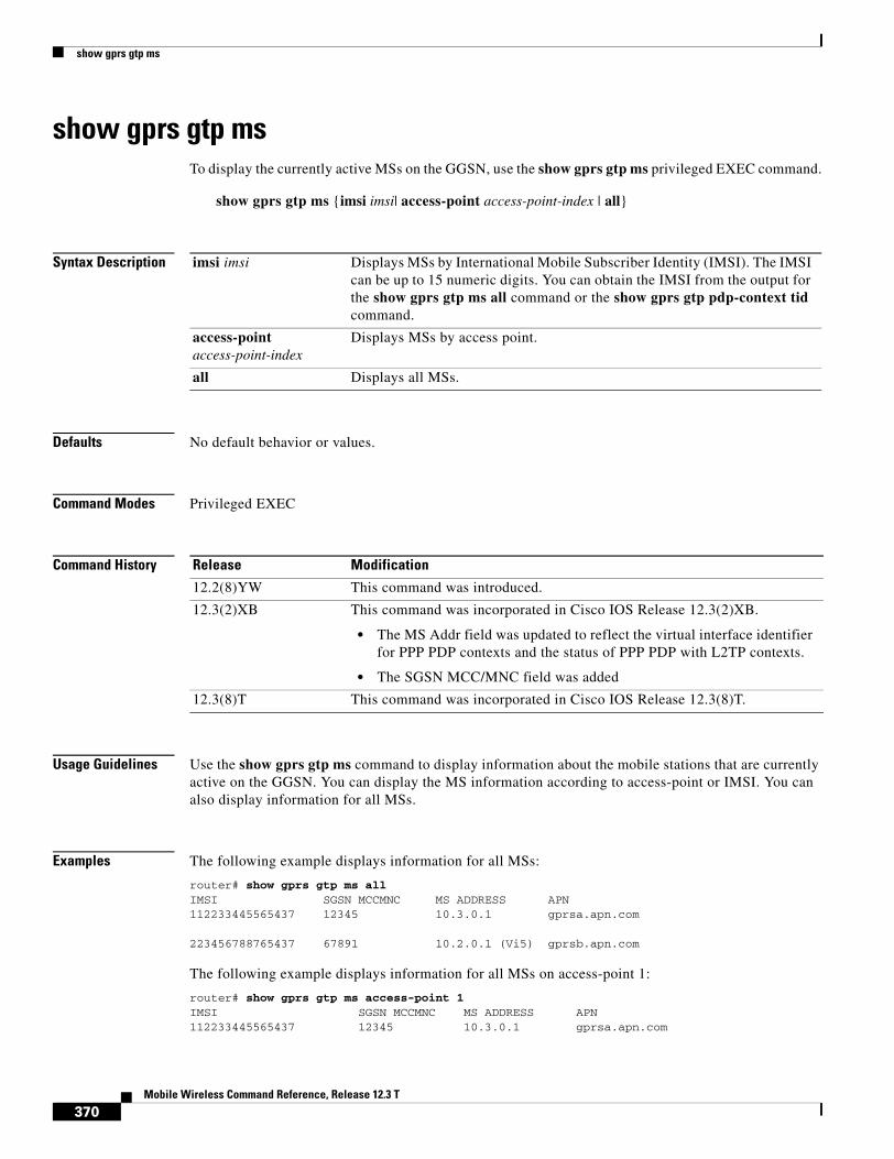
show gprs gtp ms
show gprs gtp msTo display the currently active MSs on the GGSN, use the show gprs gtp ms privileged EXEC command.
show gprs gtp ms {imsi imsi| access-point access-point-index | all}
Syntax Description
Defaults No default behavior or values.
Command Modes Privileged EXEC
Command History
Usage Guidelines Use the show gprs gtp ms command to display information about the mobile stations that are currently active on the GGSN. You can display the MS information according to access-point or IMSI. You can also display information for all MSs.
Examples The following example displays information for all MSs:
router# show gprs gtp ms allIMSI SGSN MCCMNC MS ADDRESS APN112233445565437 12345 10.3.0.1 gprsa.apn.com
223456788765437 67891 10.2.0.1 (Vi5) gprsb.apn.com
The following example displays information for all MSs on access-point 1:
router# show gprs gtp ms access-point 1IMSI SGSN MCCMNC MS ADDRESS APN112233445565437 12345 10.3.0.1 gprsa.apn.com
imsi imsi Displays MSs by International Mobile Subscriber Identity (IMSI). The IMSI can be up to 15 numeric digits. You can obtain the IMSI from the output for the show gprs gtp ms all command or the show gprs gtp pdp-context tid command.
access-point access-point-index
Displays MSs by access point.
all Displays all MSs.
Release Modification
12.2(8)YW This command was introduced.
12.3(2)XB This command was incorporated in Cisco IOS Release 12.3(2)XB.
• The MS Addr field was updated to reflect the virtual interface identifier for PPP PDP contexts and the status of PPP PDP with L2TP contexts.
• The SGSN MCC/MNC field was added
12.3(8)T This command was incorporated in Cisco IOS Release 12.3(8)T.
370Mobile Wireless Command Reference, Release 12.3 T

show gprs gtp ms
The following example displays information for all MSs on IMSI 110406080002045:
router# show gprs gtp ms imsi 110406080002045IMSI SGSN MCCMNC MS ADDRESS APN110406080002045 12345 10.10.10.2 gprsc.apn.com
number of pdp:2 reference count:1
Table 15 describes the fields shown in the display.
Related Commands
Table 15 show gprs gtp ms Field Descriptions
Field Description
IMSI International mobile subscriber identity for the MSs.
MS ADDRESS The IP address for the MSs.
Note For PPP PDP contexts, this field will also display the virtual interface identifier. For PPP PDP with L2TP contexts, this field will also display the state of the PDP context. Possible states are Pending, Forwarded, or Terminating.
APN Access point name.
number of pdp Number of PDP contexts on the MSs.
reference count Internal data structure field. It is used only for internal troubleshooting purposes.
SGSN MCCMNC MCC/MNC of the SGSN.
Command Description
show gprs gtp pdp-context
Displays a list of the currently active PDP contexts (mobile sessions).
show gprs gtp status Displays information about the current status of the GTP on the GGSN (such as activated PDP contexts, throughput, and QoS statistics).
371Mobile Wireless Command Reference, Release 12.3 T

show gprs gtp parameters
show gprs gtp parameters To display information about the current GPRS Tunneling Protocol (GTP) configuration on the GGSN, use the show gprs gtp parameters privileged EXEC command.
show gprs gtp parameters
Syntax Description This command has no arguments or keywords.
Defaults No default behavior or values.
Command Modes Privileged EXEC
Command History
Usage Guidelines Use the show gprs gtp parameters command to display the current GTP parameters configured on the GGSN.
Examples The following is sample output of the show gprs gtp parameters command:
router# show gprs gtp parametersGTP path echo interval = 60
Release Modification
12.1(1)GA This command was introduced.
12.1(5)T This command was integrated in Cisco IOS Release 12.1(5)T.
12.2(4)MX This command was incorporated in Cisco IOS Release 12.2(4)MX.
The following output fields were added to the display:
• Charging MCC Code
• Charging MNC Code
• Charging HPLMN Matching Criteria
• GTP dynamic echo-timer minimum
• GTP dynamic echo-timer smooth factor
The following output field was removed:
• GTP max hold time for old sgsn PDUs T3_tunnel
12.2(8)YD This command was incorporated in Cisco IOS Release 12.2(8)YD and the following output field was removed from the display:
• GPRS HPLMN Matching Criteria
12.2(8)B This command was incorporated in Cisco IOS Release 12.2(8)B.
12.3(4)T This command was incorporated in Cisco IOS Release 12.3(4)T.
12.3(8)T This command was incorporated in Cisco IOS Release 12.3(8)T.
372Mobile Wireless Command Reference, Release 12.3 T

show gprs gtp parameters
GTP signal max wait time T3_response = 1 GTP max retry N3_request = 5 GTP dynamic echo-timer minimum = 5 GTP dynamic echo-timer smooth factor = 2
GTP buffer size for receiving N3_buffer = 8192 GTP max pdp context = 45000 GPRS MCC Code = 310 GPRS MNC Code = 15
Table 16 describes the fields shown in the display.
.Table 16 show gprs gtp parameters Field Descriptions
Field Description
GPRS MCC Code Mobile country code (MCC) that the GGSN uses in conjunction with the mobile network node to determine whether a create PDP context request is from a roamer.
You can configure the MCC using the gprs mcc mnc command.
GPRS MNC Code Mobile network node (MNC) that the GGSN uses in conjunction with the mobile country code to determine whether a create PDP context request is from a roamer.
You can configure the MNC using the gprs mcc mnc command.
GTP buffer size for receiving N3_buffer Current size of the receive buffer (in bytes) that the GGSN uses to receive GTP signaling messages and packets sent through the tunneling protocol.
You can configure the N3 buffer using the gprs gtp n3-buffer-size command.
GTP dynamic echo-timer minimum Current minimum time period (in seconds) used by the dynamic echo timer.
You can configure the minimum value using the gprs gtp echo-timer dynamic minimum command.
GTP dynamic echo-timer smooth factor Current multiplier used by the GGSN to calculate the T-dynamic for the dynamic echo timer.
You can configure the smooth factor using the gprs gtp echo-timer dynamic smooth-factor command.
GTP max pdp context Current maximum number of PDP contexts (mobile sessions) that can be activated on the GGSN.
You can configure the maximum number of PDP context requests using the gprs maximum-pdp-context-allowed command.
GTP max retry N3_request Maximum number of times that the GGSN attempts to send a signaling request to an SGSN.
You can configure the maximum number of signaling requests made by the GGSN using the gprs gtp n3-requests command.
373Mobile Wireless Command Reference, Release 12.3 T

show gprs gtp parameters
Related Commands
GTP path echo interval Interval, in seconds, that the GGSN waits before sending an echo-request message to the SGSN.
You can configure the path echo interval using the gprs gtp path-echo-interval command.
GTP signal max wait time T3_response Interval, in seconds, that the GGSN waits before responding to a signaling request message.
You can configure the maximum interval using the gprs gtp t3-response command.
Table 16 show gprs gtp parameters Field Descriptions (continued)
Field Description
Command Description
show gprs gtp statistics Displays the current GTP statistics for the GGSN (such as IE, GTP signaling, and GTP PDU statistics).
show gprs gtp status Displays information about the current status of the GTP on the GGSN (such as activated PDP contexts, throughput, and QoS statistics).
374Mobile Wireless Command Reference, Release 12.3 T
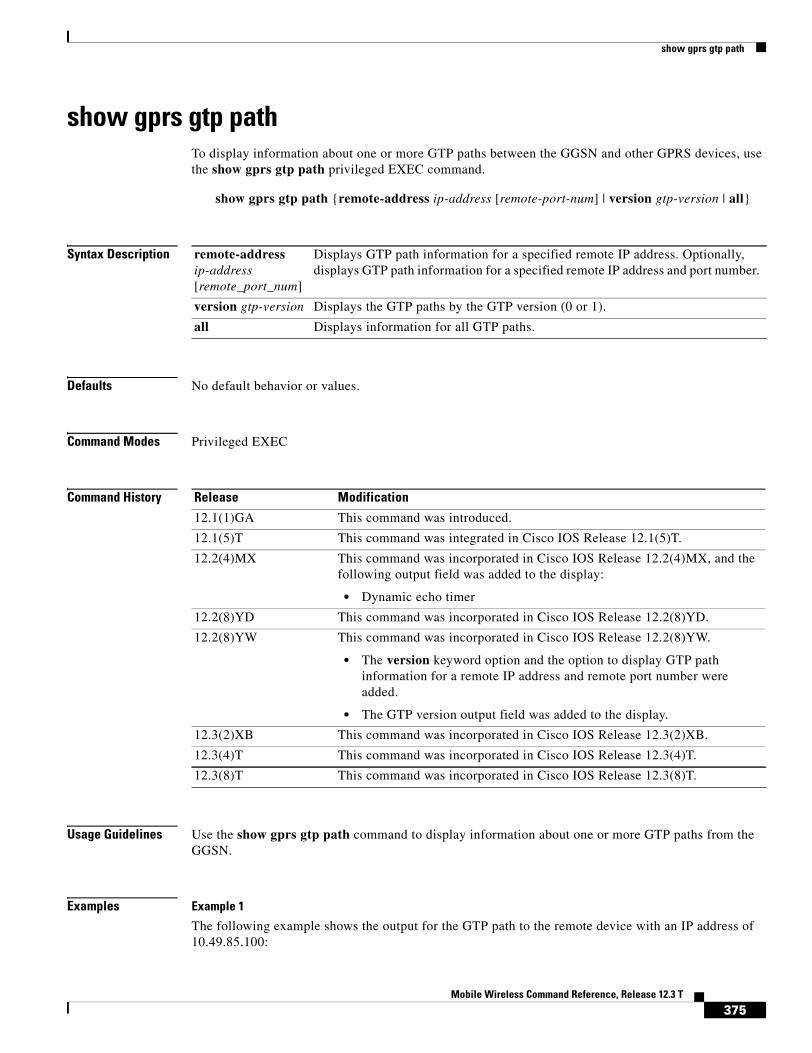
show gprs gtp path
show gprs gtp pathTo display information about one or more GTP paths between the GGSN and other GPRS devices, use the show gprs gtp path privileged EXEC command.
show gprs gtp path {remote-address ip-address [remote-port-num] | version gtp-version | all}
Syntax Description
Defaults No default behavior or values.
Command Modes Privileged EXEC
Command History
Usage Guidelines Use the show gprs gtp path command to display information about one or more GTP paths from the GGSN.
Examples Example 1
The following example shows the output for the GTP path to the remote device with an IP address of 10.49.85.100:
remote-address ip-address [remote_port_num]
Displays GTP path information for a specified remote IP address. Optionally, displays GTP path information for a specified remote IP address and port number.
version gtp-version Displays the GTP paths by the GTP version (0 or 1).
all Displays information for all GTP paths.
Release Modification
12.1(1)GA This command was introduced.
12.1(5)T This command was integrated in Cisco IOS Release 12.1(5)T.
12.2(4)MX This command was incorporated in Cisco IOS Release 12.2(4)MX, and the following output field was added to the display:
• Dynamic echo timer
12.2(8)YD This command was incorporated in Cisco IOS Release 12.2(8)YD.
12.2(8)YW This command was incorporated in Cisco IOS Release 12.2(8)YW.
• The version keyword option and the option to display GTP path information for a remote IP address and remote port number were added.
• The GTP version output field was added to the display.
12.3(2)XB This command was incorporated in Cisco IOS Release 12.3(2)XB.
12.3(4)T This command was incorporated in Cisco IOS Release 12.3(4)T.
12.3(8)T This command was incorporated in Cisco IOS Release 12.3(8)T.
375Mobile Wireless Command Reference, Release 12.3 T

show gprs gtp path
router# show gprs gtp path 10.49.85.100Local address Remote address GTP version Dynamic echo timer10.10.10.1(2123) 10.49.85.100(2123) 1 510.10.10.1(2152) 10.49.85.100(2152) 1 5
Example 2
The following example shows the output for the GTP path to the remote device with an IP address of 10.49.85.100 and remote port number 2123:
router# show gprs gtp path 10.49.85.100 2123Local address Remote address GTP version Dynamic echo timer10.10.10.1(2123) 10.49.85.100(2123) 1 5
Example 3
The following example shows the output for all paths on the GGSN that are using GTP version 1:
router# show gprs gtp path version 1Local address Remote address GTP version Dynamic echo timer10.10.10.1(3386) 10.49.85.100(3386) 1 510.10.10.1(3386) 10.7.7.7(3386) 1 2
Example 4
The following example shows the output for all GTP paths on the GGSN:
router# show gprs gtp path allTotal number of path : 3Local address Remote address GTP version Dynamic echo timer10.10.10.1(3386) 10.49.85.100(3386) 1 Disabled10.10.10.1(3386) 10.1.1.1(3386) 0 210.10.10.1(3386) 10.7.7.7(3386) 1 5
Table 17 describes the fields shown in the display.
Table 17 show gprs gtp path Field Descriptions
Field Description
Total number of path Total number of GTP paths currently established.
Dynamic echo timer Current setting (in seconds) for the dynamic echo timer. “Disabled” appears when the dynamic echo timer is not in use.
Local address IP address and port number for the local end of the GTP path.
Remote address IP address and port number for the remote end of the GTP path, such as the address of the SGSN.
GTP version Version of the GTP protocol (version 0 or 1) supported by the path.
376Mobile Wireless Command Reference, Release 12.3 T

show gprs gtp pdp-context
show gprs gtp pdp-context To display a list of the currently active PDP contexts (mobile sessions), use the show gprs gtp pdp-context privileged EXEC command.
show gprs gtp pdp-context {tid tunnel_id | ms-address ip_address [apn-index access-point-index] | imsi imsi [nsapi nsapi [tft]] | path ip-address [remote-port-num] | access-point access-point-index | pdp-type {ip | ppp} | qos-umts-class {background | conversational | interactive | streaming} | qos {precedence {low | normal | high} | qos-delay {class1 | class2 | class3 | classbesteffort} | version gtp-version} | all}
Syntax Description
Defaults No default behavior or values.
Command Modes Privileged EXEC
tid tunnel_id Displays PDP contexts by tunnel ID. This value corresponds to the IMSI plus NSAPI and can be up to 16 numeric digits.
ms-address ip_address
Displays PDP contexts for the specified mobile station IP address (in dotted-decimal format).
apn-index access-point-index
(Optional) Displays PDP contexts for the specified mobile station IP address at a particular access point. This option is required to display mobile stations that are accessing a private VPN.
imsi imsi Displays PDP contexts by International Mobile Subscriber Identity (IMSI). The IMSI value can be up to 15 numeric digits.
nsapi nsapi [tft] (Optional) Displays a particular PDP context by Network Service Access Point Identifier (NSAPI) for the specified IMSI. Optionally, displays the traffic flow template (TFT) filters associated with the NSAPI.
path ip-address [remote_port_num]
Displays PDP contexts by path. Optionally, displays PDP contexts by remote IP address and port number.
access-point access-point-index
Displays PDP contexts by access point. Possible values are 1 to 65535.
pdp-type {ip | ppp} Displays PDP contexts that are transmitted using either IP or PPP.
qos-umts-class Displays PDPs by UMTS QoS traffic class. You can specify the following traffic classes: background, conversational, interactive, and streaming. This option is available when UMTS QoS is enabled.
qos-precedence Displays PDP contexts for a specified GPRS QoS precedence type. You can specify the following precedence types: low, normal, and high. This option is available when GPRS QoS canonical QoS is enabled.
qos-delay Displays PDP contexts for a specified GPRS quality of service delay class type. You can specify the following delay class types: class1, class2, class3, and classbesteffort. This option is available when GPRS QoS delayed-based QoS is enabled.
version gtp-version Displays PDP contexts by GTP version. The possible values are 0 or 1.
all Displays all PDP contexts.
377Mobile Wireless Command Reference, Release 12.3 T
show gprs gtp pdp-context
Command History Release Modification
12.1(1)GA This command was introduced.
12.1(5)T This command was integrated into Cisco IOS Release 12.1(5)T.
12.2(1) The MS International PSTN/ISDN Number (MSISDN) field was added to the output display.
12.2(4)MX This command was incorporated in Cisco IOS Release 12.2(4)MX.
• The pdp-type ppp and qos-delay options were added to the command.
• The following fields were added to the output display of the tid version of this command:
– cef_down_byte
– cef_down_pkt
– cef_drop
– cef_up_byte
– cef_up_pkt
– gtp pdp idle time
• The Network Init Information section was added to the output display of the tid version of this command with the following new fields:
– Buf.Bytes
– MNRG Flag
– NIP State
– PDU Discard Flag
– SGSN Addr
• The following fields were removed from the output display of the tid version of this command:
– fast_up_pkt
– fast_up_byte
– fast_down_pkt
– fast_down_byte
– fast_drop
• The “dynamic?” and “Dynamic” fields were removed from the output display of the all and tid versions of this command, and were replaced by the Source field.
12.2(8)YD This command was incorporated in Cisco IOS Release 12.2(8)YD and the following fields were added to the output display of the tid version of this command:
• primary dns
• secondary dns
• primary nbns
• secondary nbns
378Mobile Wireless Command Reference, Release 12.3 T

show gprs gtp pdp-context
Usage Guidelines Use the show gprs gtp pdp-context command to display the currently active PDP contexts on the GGSN. You can display PDP contexts by tunnel ID, by IMSI, by access point, by PDP type, and by GPRS QoS precedence, UMTS QoS traffic class, or you can display all PDP contexts.
Several versions of the show gprs gtp pdp-context command display similar output. The examples provided show these two different types of output.
Interpreting the Effective Bandwidth
Example 2 provides sample output from the show gprs gtp pdp-context tid command, which includes the field called effective bandwidth (in bps). The effective bandwidth is determined according to the GPRS QoS canonical QoS class (premium, normal, or best effort) for the PDP context; it does not represent the actual bandwidth in use by the PDP context. The potential number of supported PDP contexts for that class of QoS can then be calculated according to the total amount of bandwidth (GSN resource) available to the GGSN.
For more information about GPRS QoS canonical QoS and resources on the GGSN, see the “Configuring QoS on the GGSN” chapter in the Cisco IOS Mobile Wireless Configuration Guide.
12.2(8)YW This command was incorporated in the 12.2(8)YW.
• The the option of displaying PDP contexts by remote IP address and port number was added.
• The delay Qos class(req.) output field was added to the display of the tid version of this command when the mapping of GPRS QoS categories to delay QoS classes is enabled.
• The ms-address, imsi, qos-umts-class and version options were added to the command.
• The ggsn_addr_signal field was changed to the sgsn_addr_data in the output display of the tid version of this command.
• The following fields were added to the output display of the tid version of this command:
– control teid local
– control teid remote
– data teid local
– data teid remote
– primary pdp
– nsapi
12.3(2)XB This command was incorporated in Cisco IOS Release 12.3(2)XB and the MS Addr field updated to reflect the virtual interface identifier for PPP PDP and PPP-REGEN contexts and the status of PPP PDP with L2TP contexts.
12.3(4)T This command was incorporated in Cisco IOS Release 12.3(4)T.
12.3(8)T This command was incorporated in Cisco IOS Release 12.3(8)T and the Framed-route and mask fields were added.
Release Modification
379Mobile Wireless Command Reference, Release 12.3 T
show gprs gtp pdp-context
Examples Example 1The following is sample output of the show gprs gtp pdp-context all command:
router# show gprs gtp pdp-context allTID MS Addr Source SGSN Addr APN1234567890123456 10.11.1.1 Radius 10.4.4.11 www.pdn1.com2345678901234567 Forwarded (Vi5) IPCP 10.4.4.11 www.pdn2.com3456789012345678 10.21.1.1 (Vi7) IPCP 10.1.4.11 www.pdn3.com4567890123456789 10.31.1.1 (Vi9) IPCP 10.1.4.11 www.pdn4.com5678901234567890 10.41.1.1 Static 10.4.4.11 www.pdn5.com
Note The same output fields shown in Example 1 also appear when you use the access-point, path, pdp-type, qos-delay, or qos-precedence keyword options of the show gprs gtp pdp-context command.
The following table describes the fields shown in the display.
Example 2The following is sample output from the show gprs gtp pdp-context tid command for a PDP context created by GTP version 1 and GPRS QoS canonical QoS is configured:
router#show gprs gtp pdp-context tid 1111111111111111TID MS Addr Source SGSN Addr APN1111111111111111 10.1.1.1 Radius 10.8.8.1 dns.com
current time :Mar 18 2002 11:24:36 user_name (IMSI):1111111111111111 MS address:10.1.1.1
Field Description
APN Access point name where the PDP context is active.
MS Addr IP address of the mobile station.
Note For PPP PDP and PPP-REGEN contexts, this field will also display the virtual interface identifier. For PPP PDP with L2TP contexts, this field will also display the state of the PDP context. Possible states are Pending, Forwarded, or Terminating.
SGSN Addr IP address of the SGSN that is processing the packets.
Source Source of IP addressing for the MS. The possible values are:
• DHCP—Dynamic address allocation using DHCP.
• IPCP—Dynamic address allocation for PPP PDP types, or for IP PDP types with PPP regeneration, using PPP IP Control Protocol.
• Pending—Waiting for dynamic address allocation. Dynamic address source is unknown.
• Radius—Dynamic address allocation using RADIUS.
• Static—IP address is not dynamically assigned.
TID Tunnel ID for the PDP context.
380Mobile Wireless Command Reference, Release 12.3 T

show gprs gtp pdp-context
MS International PSTN/ISDN Number (MSISDN):ABC sgsn_addr_signal:10.8.8.1 sgsn_addr_data:10.8.0.1
control teid local: 0x63493E0Ccontrol teid remove: 0x00000121data teid local: 0x63483E10data teid remote: 0x00000121primary pdp: Y nsapi: 0
signal_sequence: 0 seq_tpdu_up: 0 seq_tpdu_down: 0 upstream_signal_flow: 1 upstream_data_flow: 2 downstream_signal_flow:14 downstream_data_flow:12 RAupdate_flow: 0 pdp_create_time: Mar 18 2002 09:58:39 last_access_time: Mar 18 2002 09:58:39 mnrgflag: 0 tos mask map:00 gtp pdp idle time:72 gprs qos_req:091101 canonical Qos class(req.):01 gprs qos_neg:25131F canonical Qos class(neg.):01 effective bandwidth:0.0 rcv_pkt_count: 0 rcv_byte_count: 0 send_pkt_count: 0 send_byte_count: 0 cef_up_pkt: 0 cef_up_byte: 0 cef_down_pkt: 0 cef_down_byte: 0 cef_drop: 0
Src addr violation: 2 paks, 1024 bytesDest addr violation: 2 paks, 1024 bytesRedirected mobile-to-mobile traffic: 2 paks, 1024 bytes
charging_id: 29160231 pdp reference count:2 primary dns: 2.2.2.2 secondary dns: 4.4.4.4 primary nbns: 3.3.3.3 secondary nbns: 5.5.5.5 ntwk_init_pdp: 0
Framed_route 5.5.5.0 mask 255.255.255.0
** Network Init Information ** MNRG Flag: 0 PDU Discard Flag: 0 SGSN Addr: 172.16.44.1 NIP State: NIP_STATE_WAIT_PDP_ACTIVATION Buf.Bytes: 500
Table 18 describes the fields shown in the display.
Note The Network Init Information section of the output appears only while network-initiated PDP contexts are being processed by the GGSN.
Note The same output fields shown in Example 2 also appear when you use the imsi keyword option of the show gprs gtp pdp-context command.
381Mobile Wireless Command Reference, Release 12.3 T

show gprs gtp pdp-context
Table 18 show gprs gtp pdp-context tid Field Descriptions
Field Description
APN Access point name where the PDP context is active.
canonical Qos class (neg.) Negotiated canonical quality of service class for the PDP context, with the following values:
• 01—Best effort
• 02—Normal
• 03—Premium
This field displays when GPRS QoS canonical QoS is enabled on the GGSN.
canonical Qos class (req.) Requested GPRS canonical QoS class by the PDP context, with the following values:
• 01—Best effort
• 02—Normal
• 03—Premium
This field displays when GPRS QoS canonical QoS is enabled on the GGSN.
cef_down_byte Total number of G-PDU bytes CEF switched on the downlink, from the GGSN to the SGSN.
cef_down_pkt Total number of G-PDU packets CEF switched on the downlink, from the GGSN to the SGSN.
cef_drop Total number of G-PDU packets dropped during CEF switching.
cef_up_byte Total number of G-PDU bytes CEF switched on the uplink, from the SGSN to the GGSN.
cef_up_pkt Total number of G-PDU packets CEF switched on the uplink, from the SGSN to the GGSN.
charging_id Unique 4-octet value generated by the GGSN for the PDP context. The value 0 is reserved.
control teid local Uplink tunnel endpoint identifier (TEID) chosen by the GGSN for control plane messages.
This field displays for PDP contexts created with GTP version 1.
control teid remote Downlink TEID chosen by the SGSN for control plane messages.
This field displays for PDP contexts created with GTP version 1.
current time Date and time of the show command output.
data teid local Uplink TEID chosen by the GGSN for G-PDUs.
This field displays for PDP contexts created with GTP version 1.
data teid remote Downlink TEID chosen by the SGSN for PDUs.
This field displays for PDP contexts created with GTP version 1.
382Mobile Wireless Command Reference, Release 12.3 T
show gprs gtp pdp-context
Dest addr violation Number of packets (and bytes) dropped by the GGSN because of a source address violation.
This field displays only when the security verify destination command is configured.
Note This field does not apply to APNs using VRF. In addition, verification of destination addresses does not apply to GTP-PPP regeneration or GTP-PPP with L2TP.
downstream_data_flow Flow label of downlink G-PDUs.
downstream_signal_flow Flow label of downlink signaling messages.
effective bandwidth Estimated number of bits per second allocated by the GGSN for this PDP context. The effective bandwidth is determined according to the QoS class (premium, normal, or best effort) for the PDP context. The potential number of supported PDP contexts for that class of QoS can be calculated according to the total amount of bandwidth (GSN resource) available to the GGSN.
This field displays when canonical QoS is enabled on the GGSN.
Note The effective bandwidth does not represent actual bandwidth usage.
Framed_route Framed-Route, attribute 22, for the PDP context, downloaded from the RADIUS server during authentication and authorization.
gprs qos_neg Negotiated quality of service for the PDP context. The field is in the format vwxyzz, which represents the following QoS classes (as defined in the GSM specifications for quality of service profiles):
• v—Delay class
• w—Reliability class
• x—Peak throughput class
• y—Precedence class
• zz—Mean throughput class
Note To determine the GPRS QoS attributes shown in this output, you must convert the value to binary and interpret the values to find the corresponding class attributes. Some of the bits represent “don’t care” bits and are not interpreted as part of the final value. For more information about how to interpret this value, see the “Interpreting the Requested and Negotiated GPRS QoS” section of the “Configuring QoS” chapter in the Cisco IOS Mobile Wireless Configuration Guide.
Table 18 show gprs gtp pdp-context tid Field Descriptions (continued)
Field Description
383Mobile Wireless Command Reference, Release 12.3 T

show gprs gtp pdp-context
gprs qos_req Requested quality of service by the PDP context. The field is in the format vwxyzz, which represents the following QoS classes (as defined in the GSM specifications for GPRS QoS profiles):
• v—Delay class
• w—Reliability class
• x—Peak throughput class
• y—Precedence class
• zz—Mean throughput class
Note See the Note in the description of the gprs qos_neg output field above.
gtp pdp idle time Current setting for the gprs idle-pdp-context purge-timer command, unless the session idle-time command is configured. Indicates the amount of idle time (in hours) allowed before PDP contexts are deleted.
last_access_time Time when the PDP context for this TID was last accessed. The date format is MMM DD YYYY. The time format is hours:minutes:seconds.
When a signaling packet or data packet for a PDP context arrives on the GGSN, the last_access_time is reset to the current date and time. If the last_access_time exceeds the purge timer for idle PDP contexts, then the PDP context is purged by the GGSN.
mask Framed-Route subnet.
mnrgflag Mobile not reachable flag, with the following values:
• 0—flag is off.
• 1—flag is on, indicating that the MS is not reachable
MS_ADDR and MS Address IP address of the mobile station.
Note For PPP PDP and PPP-REGEN contexts, this field will also display the virtual interface identifier. For PPP PDP with L2TP contexts, this field will also display the state of the PDP context. Possible states are Pending, Forwarded, or Terminating.
MS International PSTN/ISDN Number (MSISDN)
Integrated Services Digital Network (ISDN) number of the mobile station.
nsapi Network Service Access Point Identifier (NSAPI).
This field displays for PDP contexts created with GTP version 1.
ntwk_init_pdp Network initiated PDP context indicator, with the following values:
• 0—Not a network initiated PDP context. This indicates a mobile initiated PDP context.
• 1—Network initiated PDP context
Table 18 show gprs gtp pdp-context tid Field Descriptions (continued)
Field Description
384Mobile Wireless Command Reference, Release 12.3 T

show gprs gtp pdp-context
pdp_create_time Time when the PDP context for this TID was created. The date format is MMM DD YYYY. The time format is hours:minutes:seconds.
pdp reference count Number of subsystems on the GGSN that are aware of the PDP context. For example, if both the charging and GTP subsystems are aware of the PDP context, then the pdp reference counter shows a value of 2.
primary dns IP address of the primary DNS server.
primary nbns IP address of the primary NetBIOS Name Service (NBNS).
primary pdp Whether the PDP is primary or secondary. Possible values are Y (PDP is primary) or N (PDP is secondary).
This field displays for PDP contexts created with GTP version 1.
RAupdate_flow Flow Label Data II information element in GTP header. This IE contains the flow label for data transmission between old and new SGSNs for a particular PDP context. This IE is requested by the new SGSN.
rcv_byte_count Total number of G-PDU bytes received. For the GGSN, this is the total byte count on the uplink.
rcv_pkt_count Total packet count of received G-PDUs. For the GGSN, this is the total byte count on the uplink.
Redirected mobile-to-mobile traffic
Number of packets (and bytes) dropped at the APN from which they exit because mobile-to-mobile traffic has been redirected. This field displays only when the redirect intermobile ip command is configured.
secondary dns IP address of the secondary DNS server.
secondary nbns IP address of the secondary NBNS.
send_byte_count Total number of G-PDU bytes sent by the GSN (GGSN or SGSN D-node).
send_pkt_count Total number of G-PDU packets sent by the GSN (GGSN or SGSN D-node).
seq_tpdu_down Last sequence number used in the downlink T-PDU. This number wraps to 0 after 65535.
seq_tpdu_up Last sequence number used in the uplink T-PDU. This number wraps to 0 after 65535.
sgsn_addr_signal IP address of the SGSN that is processing the packets.
sgsn_addr_data IP address of the SGSN that is processing tunnel packet data units (TPDUs).
signal_sequence Last sequence number used in the GTP signaling message.
Table 18 show gprs gtp pdp-context tid Field Descriptions (continued)
Field Description
385Mobile Wireless Command Reference, Release 12.3 T
show gprs gtp pdp-context
Table 19 describes the fields shown in the Network Init Information section of the output.
Note The Network Init Information section of the output appears only when network-initiated PDP contexts are unsuccessful.
Source Source of IP addressing for the MS. The possible values are:
• DHCP—Dynamic address allocation using DHCP.
• IPCP—Dynamic address allocation for PPP PDP types, or for IP PDP types with PPP regeneration, using PPP IP Control Protocol.
• Pending—Waiting for dynamic address allocation. Dynamic address source is unknown.
• Radius—Dynamic address allocation using RADIUS.
• Static—IP address is not dynamically assigned.
Src addr violation Number of packets (and bytes) dropped because of source address violation. This field displays only when the security verify source command is configured.
TID Tunnel ID for the PDP context.
tos mask map ToS value in IP header of this PDP context.
umts qos_req Requested UMTS quality of service by the PDP context. This field displays when UMTS QoS is enabled on the GGSN.
umts qos_neg Negotiated UMTS quality of service for the PDP context. This field displays when UMTS QoS is enabled on the GGSN.
upstream_data_flow Flow label of uplink G-PDUs.
upstream_signal_flow Flow label of uplink signaling messages.
user_name (IMSI) International mobile subscriber identity for the PDP context.
Table 18 show gprs gtp pdp-context tid Field Descriptions (continued)
Field Description
Table 19 show gprs gtp pdp-context tid Network Init Information Field Descriptions
Field Description
Buf.Bytes Number of bytes currently buffered for this network-initiated PDP context.
last_access_time Time when the PDP context for this TID was last accessed. The date format is MMM DD YYYY. The time format is hours:minutes:seconds.
When a signaling packet or data packet for a PDP context arrives on the GGSN, the last_access_time is reset to the current date and time. If the last_access_time exceeds the purge timer for idle PDP contexts, then the PDP context is purged by the GGSN.
386Mobile Wireless Command Reference, Release 12.3 T

show gprs gtp pdp-context
Related Commands
MNRG Flag Mobile not reachable flag, with the following values:
• 0—flag is off.
• 1—flag is on, indicating that the MS is not reachable
NIP State State information for the network initiated PDP process on the GGSN.
PDU Discard Flag Discarded PDU indicator for a network initiated PDP context, with the following values:
• 0—PDUs are not discarded. This indicates that PDUs for a network initiated PDP context are being sent to the SGSN.
• 1—PDUs are being discarded by the GGSN. PDUs are discarded by the GGSN when a network initiated PDP context procedure is unsuccessful. This occurs when the SGSN sends a rejection of the PDP context request to the GGSN with a Cause value of either “MS Refuses” or “MS is not GPRS Responding.”
When the flag is set to 1, the GGSN ignores PDUs destined for that MS for the specified PDU discard period. The default period is 300 seconds (5 minutes). You can configure the PDU discard time using the gprs ntwk-init-pdp pdu-discard-period command.
SGSN Addr IP address of the SGSN that is associated with the network-initiated procedure for this PDP context (used for paging).
Table 19 show gprs gtp pdp-context tid Network Init Information Field Descriptions (continued)
Field Description
Command Description
show gprs access-point Displays information about access points on the GGSN.
show gprs gtp status Displays information about the current status of the GTP on the GGSN (such as activated PDP contexts, throughput, and QoS statistics).
387Mobile Wireless Command Reference, Release 12.3 T

show gprs gtp statistics
show gprs gtp statisticsTo display the current GPRS Tunneling Protocol (GTP) statistics for the GGSN (such as IE, GTP signaling, and GTP PDU statistics), use the show gprs gtp statistics privileged EXEC command.
show gprs gtp statistics
Syntax Description This command has no arguments or keywords.
Defaults No default behavior or values.
Command Modes Privileged EXEC
Command History Release Modification
12.1(1)GA This command was introduced.
12.1(2)GB This command was integrated in Cisco IOS Release 12.1(2)GB and the following fields were added to the output display:
• total created_pdp
• total deleted_pdp
12.1(5)T This command was integrated in Cisco IOS Release 12.1(5)T.
12.2(4)MX This command was incorporated in Cisco IOS Release 12.2(4)MX, and the following new output fields were added:
• ntwk_init_pdp_act_rej
• ppp_regen_pending
• ppp_regen_pending_peak
• ppp_regen_total_drop
• ppp_regen_no_resource
• total created_ppp_pdp
• total ntwkInit created pdp
12.2(8)YD This command was incorporated in Cisco IOS Release 12.2(8)YD.
12.2(8)YW This command was incorporated in the Cisco IOS Release 12.2(8)YW and the following new output fields were added:
• tft_semantic_error
• tft_syntactic_error
• packet_filter_semantic_error
• packet_filter_syntactic_error
• total deleted_ppp_pdp
12.3(2)XB This command was incorporated in Cisco IOS Release 12.3(2)XB.
388Mobile Wireless Command Reference, Release 12.3 T

show gprs gtp statistics
Usage Guidelines Use the show gprs gtp statistics command to display the GTP statistics for the GGSN. The counter values displayed by this command represent totals accumulated since the last time the statistical counters were cleared using the clear gprs gtp statistics command.
Examples The following is sample output of the show gprs gtp statistics command:
router# show gprs gtp statisticsGPRS GTP Statistics: version_not_support 0 msg_too_short 0 unknown_msg 0 unexpected_sig_msg 0 unexpected_data_msg 0 mandatory_ie_missing 0 mandatory_ie_incorrect 0 optional_ie_invalid 0 ie_unknown 0 ie_out_of_order 0 ie_unexpected 0 ie_duplicated 0 optional_ie_incorrect 0 pdp_activation_rejected 10981 tft_semantic_error 0 tft_syntactic_error 0 pkt_ftr_semantic_error 0 pkt_ftr_syntactic_error 0 non_existent 0 path_failure 0 total_dropped 0 signalling_msg_dropped 0 data_msg_dropped 0 no_resource 0 get_pak_buffer_failure 0 rcv_signalling_msg 15401 snd_signalling_msg 19243 rcv_pdu_msg 0 snd_pdu_msg 0 rcv_pdu_bytes 0 snd_pdu_bytes 0 total created_pdp 3761 total deleted_pdp 3661 total created_ppp_pdp 0 total deleted_ppp_pdp 0 ppp_regen_pending 0 ppp_regen_pending_peak 0 ppp_regen_total_drop 0 ppp_regen_no_resource 0 ntwk_init_pdp_act_rej 0 total ntwkInit created pdp 0
GPRS Network behind mobile Statistics: network_behind_ms APNs 1 total_download_route 5 save_download_route_fail 0 insert_download_route_fail 2 total_insert_download_route 3
Table 20 describes the fields shown in the display:
12.3(4)T This command was incorporated in Cisco IOS 12.3(4)T.
12.3(8)T This command was incorporated in GGSN 5.0 and the following new output fields were added:
• insert_download_route_fail
• network_behind_ms APNs
• save_download_route_fail
• total_download_route
• total_insert_download_route
• unsupported_comp_exthdr
Release Modification
389Mobile Wireless Command Reference, Release 12.3 T

show gprs gtp statistics
Table 20 show gprs gtp statistics Field Descriptions
Field Description
data_msg_dropped Number of GTP PDUs dropped.
get_pak_buffer_failure Number of times the GGSN has failed to obtain a GTP packet.
ie_duplicated Number of GTP messages received with a duplicated information element.
ie_out_of_order Number of GTP messages received with an information element (IE) out of order.
ie_unexpected Number of GTP messages received with an information element that not expected in the GTP message, but is defined in GTP. GTP messages with unexpected IEs are processed as if the IE was not present.
ie_unknown Number of GTP messages received with an information element of an unknown type.
insert_download_route_fail Number of routes downloaded from the RADIUS server that failed to be inserted into the routing table because they conflicted with others.
mandatory_ie_incorrect Number of GTP messages received with an incorrect mandatory information element—for example, with an information element that has an incorrect length.
mandatory_ie_missing Number of GTP messages received with a missing mandatory information element.
msg_too_short Number of GTP messages received that are too short to hold the GTP header for the supported GTP version.
network_behind_ms APNs Number of APNs configured to support routing behind the MS.
no_resource Number of times a resource was not available for transmitting GTP messages. For example, the router may be out of memory.
non-existent Number of
ntwk_init_pdp_act_rej Number of rejected PDP context requests that were initiated by the network (PDN).
optional_ie_incorrect Number of GTP messages received with an optional IE that is incorrect, which prevents the GGSN from processing the GTP message correctly.
optional_ie_invalid Number of GTP messages received with an information element that contains a value that is not within the defined range for that IE. GTP messages with invalid optional IEs are processed as if the IE was not present.
packet_filter_semantic_error Number of GTP messages received with an IE element with packet filter semantic errors. A semantic error is when the defined format of the information element (IE) is valid but the content of the IE is inconsistent or invalid.
packet_filter_syntactic_error Number of GTP messages received with an IE element with packet filter syntactic errors. A syntactic error is when the coding of the IE is invalid.
390Mobile Wireless Command Reference, Release 12.3 T

show gprs gtp statistics
path_failure Number of path failures on the GPRS Support Node (GSN).
pdp_activation_rejected Number of times a request to activate a PDP context was rejected.
ppp_regen_no_resource Total number of rejected responses to create PDP context and delete PDP context requests due to unavailable resource on the GGSN for PPP regeneration.
ppp_regen_pending Number of pending PPP regeneration sessions.
ppp_regen_pending_peak Maximum number of pending PPP regeneration sessions since the statistic was cleared.
ppp_regen_total_drop Total number of create PDP context and delete PDP context requests that were dropped due to the threshold limit being reached for maximum number of PPP regeneration sessions allowed on the GGSN.
rcv_pdu_bytes Number of bytes received in protocol data units (PDUs).
rcv_pdu_msg Number of PDU messages received.
rcv_signaling_msg Number of GTP signaling messages received.
save_download_route_fail Number of times a downloaded route could not be saved because there was not enough memory.
signalling_msg_dropped Number of GTP signaling messages dropped.
snd_pdu_bytes Number of PDU bytes sent.
snd_pdu_msg Number of PDU messages sent.
snd_signalling_msg Number of GTP signaling messages sent.
tft_semantic_error Number of GTP messages received with an IE element with traffic flow template (TFT) semantic errors. A semantic error is when the defined format of the information element (IE) is valid but the content of the IE is inconsistent or invalid.
tft_syntactic_error Number of GTP messages received with an IE element with TFT syntactic errors. A syntactic error is when the coding of the IE is invalid.
total created_pdp Total number of PDP contexts created since system startup (supports Special Mobile Group (SMG)-28 standards level and later)
total created_ppp_pdp Total number of PDP contexts created for PPP PDP PDU types.
total deleted_pdp Total number of PDP contexts deleted since system startup (supports SMG-28 standards level and later)
total deleted_ppp_pdp Total number of PDP contexts created for PPP PDP PDU types deleted since system startup.
total_download_route Total number of routes downloaded from the RADIUS server.
total_dropped Number of GTP messages dropped.
Table 20 show gprs gtp statistics Field Descriptions
Field Description
391Mobile Wireless Command Reference, Release 12.3 T

show gprs gtp statistics
Related Commands
total_insert_download_route Total number of routes downloaded from the RADIUS server that have been inserted into the routing table by the GGSN.
total ntwkInit created pdp Number of PDP context requests activated by the GGSN that were initiated by the network (PDN).
unexpected_data_msg Number of GTP PDUs received for nonexistent PDP contexts.
unexpected_sig_msg Number of unexpected GTP signaling messages received—for example, a message received on the wrong end of the tunnel or a response message received for a request that was not sent by the GGSN.
unknown_msg Number of unknown GTP messages received.
version_not_support Number of GTP messages received from devices running an unsupported version of the GTP.
Table 20 show gprs gtp statistics Field Descriptions
Field Description
Command Description
show gprs gtp parameters Displays the current GTP parameters configured on the GGSN.
show gprs gtp path Displays information about one or more GTP paths between the GGSN and other GPRS devices.
show gprs gtp pdp-context Displays a list of the currently active PDP contexts (mobile sessions).
show gprs gtp status Displays information about the current status of GTP on the GGSN.
show gprs charging statistics Displays current statistics for the transfer of charging packets between the GGSN and charging gateways.
392Mobile Wireless Command Reference, Release 12.3 T

show gprs gtp status
show gprs gtp statusTo display information about the current status of the GPRS Tunneling Protocol (GTP) on the GGSN (such as activated PDP contexts, throughput, and QoS statistics), use the show gprs gtp status privileged EXEC command.
show gprs gtp status
Syntax Description This command has no arguments or keywords.
Defaults No default behavior or values.
Command Modes Privileged EXEC
Command History Release Modification
12.1(1)GA This command was introduced.
12.1(5)T This command was integrated in Cisco IOS Release 12.1(5)T.
12.2(4)MX This command was incorporated in Cisco IOS Release 12.2(4)MX, and the following output fields were added:
• activated_ppp_pdp
• activated_ppp_regen_pdp
• ntwk_init_pdp
• qos_delay1_pdp
• qos_delay2_pdp
• qos_delay3_pdp
• qos_delaybesteffort_pdp
12.2(8)YD This command was incorporated in Cisco IOS Release 12.2(8)YD.
12.2(8)YW This command was incorporated in the Cisco IOS Release 12.2(8)YW and the following output fields were added:
• activated gtpv0 pdp
• activated gtpv1 pdp
• activated ms
12.3(2)XB This command was incorporated in Cisco IOS Release 12.3(2)XB.
12.3(4)T This command was incorporated in Cisco IOS Release 12.3(4)T.
12.3(8)T This command was incorporated in Cisco IOS Release 12.3(8)T.
393Mobile Wireless Command Reference, Release 12.3 T

show gprs gtp status
Usage Guidelines Use the show gprs gtp status command to display information about the status of GTP running on the GGSN. The output fields displayed by the show gprs gtp status command vary by the type of QoS method that is enabled on the GGSN.
The values displayed by the show gprs gtp status command show the current counts since the GGSN was started. Unlike the values displayed by the show gprs gtp statistics command, these values cannot be cleared.
Examples Example 1
The following example shows output from the show gprs gtp status command for an activated network-initiated PDP context using the canonical QoS method:
Router# show gprs gtp statusGPRS GTP Status: gsn_used_bandwidth 7399 total gsn_resource 4294967295 activated_pdp 1 ntwk_init_pdp 1 mean_throughput_premium 1110.000 mean_throughput_normal 0.000 mean_throughput_besteffort 0.000 qos_high_pdp 1 qos_normal_pdp 0 qos_low_pdp 0 qos premium mean-throughput-deviation 0.100
Example 2
The following example shows output from the show gprs gtp status command for activated 2 PPP PDP contexts using the canonical QoS method. Both of the PDP contexts are using the premium QoS class, indicated by the qos_high_pdp output field:
Router# show gprs gtp statusGPRS GTP Status: gsn_used_bandwidth 14798 total gsn_resource 1048576 activated_pdp 2 ntwk_init_pdp 0 activated_ppp_pdp 2 mean_throughput_premium 2220.000 mean_throughput_normal 0.000 mean_throughput_besteffort 0.000 qos_high_pdp 2 qos_normal_pdp 0 qos_low_pdp 0 qos premium mean-throughput-deviation 0.100
Note All output fields except those related to PDP context creation appear only when canonical QoS is enabled on the GGSN.
Example 3
The following example shows output from the show gprs gtp status command for 3 activated PPP regenerated PDP contexts not using either the canonical or delay QoS method:
Router# show gprs gtp statusGPRS GTP Status: activated_pdp 3 ntwk_init_pdp 0 activated_ppp_pdp 0 activated_ppp_regen_pdp 3
Example 4
The following example shows output from the show gprs gtp status command for 4 activated PDP contexts using the delay QoS method. The PDP contexts are using the delay class 1, delay class 2, and delay best effort class:
Router# show gprs gtp statusGPRS GTP Status:
394Mobile Wireless Command Reference, Release 12.3 T

show gprs gtp status
activated_pdp 4 ntwk_init_pdp 0 activated_ppp_pdp 0 activated_ppp_regen_pdp 0 qos_delay1_pdp 1 qos_delay2_pdp 1 qos_delay3_pdp 0 qos_delaybesteffort_pdp 2
Example 5
The following example shows output from the show gprs gtp status command with 2 active PDP contexts using GTP version 1, and 5 active mobile stations:
router# show gprs gtp statusGPRS GTP Status: activated_pdp 2 ntwk_init_pdp 0 activated_ppp_pdp 0 activated gtpv0 pdp 0activated gtpv1 pdp 2activated ms 5
Table 21 describes the fields shown in the display.
Table 21 show gprs gtp status Field Descriptions
Field Description
activated gtpv0 pdp Number of PDP contexts created with GTP version 0.
activated gtpv1 pdp Number of PDP contexts created with GTP version 1.
activated ms Number of active mobile stations (MS).
activated_pdp Number of PDP contexts currently activated. This number includes PDP contexts initiated by both the MS and the network (PDN).
activated_ppp_pdp Number of point-to-point protocol PDP contexts currently activated.
activated_ppp_regen_pdp Number of point-to-point protocol PDP contexts created on the GGSN.
gsn_used_bandwidth Currently used bandwidth, in bits per second. Represents the cumulative bandwidth for all active PDP context requests currently using canonical QoS. This field only appears when canonical QoS is enabled.
mean_throughput_besteffort Total mean throughput for best effort QoS users, in bits per second. Represents the cumulative throughput for all active PDP context requests classified in the best effort canonical QoS class. This field only appears when canonical QoS is enabled.
mean_throughput_normal Total mean throughput for normal QoS users, in bits per second. Represents the cumulative throughput for all active PDP context requests classified in the normal canonical QoS class. This field only appears when canonical QoS is enabled.
mean_throughput_premium Total mean throughput for premium QoS users, in bits per second. Represents the cumulative throughput for all active PDP context requests classified in the premium canonical QoS class. This field only appears when canonical QoS is enabled.
ntwk_init_pdp Current number of active PDP contexts that are initiated by the network to an MS.
395Mobile Wireless Command Reference, Release 12.3 T

show gprs gtp status
Related Commands
qos_delay1_pdp Current number of active PDP contexts that are classified in the class 1 delay QoS class. This field only appears when delay QoS is enabled.
qos_delay2_pdp Current number of active PDP contexts that are classified in the class 2 delay QoS class. This field only appears when delay QoS is enabled.
qos_delay3_pdp Current number of active PDP contexts that are classifed in the class 3 delay QoS class. This field only appears when delay QoS is enabled.
qos_delaybesteffort_pdp Current number of active PDP contexts that are classified in the best effort delay QoS class. This field only appears when delay QoS is enabled.
qos_high_pdp Current number of active PDP contexts that are classified in the premium canonical QoS class. This field only appears when canonical QoS is enabled.
qos_low_pdp Current number of PDP contexts that are classified in the best effort canonical QoS class. This field only appears when canonical QoS is enabled.
qos_normal_pdp Current number of PDP contexts that are classified in the normal canonical QoS class. This field only appears when canonical QoS is enabled.
qos premium mean-throughput-deviation
Current mean throughput deviation for QoS. This field only appears when canonical QoS is enabled.
total gsn_resource Currently available GSN resources. This field only appears when canonical QoS is enabled.
Table 21 show gprs gtp status Field Descriptions
Field Description
Command Description
encapsulation gtp Sets the encapsulation type for all connections established using the virtual template to GTP. This is mandatory for all GTP interfaces.
show gprs gtp statistics
Displays the current GTP statistics for the GGSN.
396Mobile Wireless Command Reference, Release 12.3 T

show gprs gtp-director pending-request
show gprs gtp-director pending-requestTo display a list of the create PDP context requests sent by GDM to a real GGSN that are pending expiration of the retry timer, use the show gprs gtp-director pending-request privileged EXEC command.
show gprs gtp-director pending-request {tid hex-data | all}
Syntax Description
Defaults No default behavior or values.
Command Modes Privileged EXEC
Command History
Usage Guidelines Use the show gprs gtp-director pending-request command to display a list of the create PDP context requests currently sent by GDM to a real GGSN that are pending expiration of the retry timer.
Note The show gprs gtp-director pending-request command shows only those PDP contexts that have been requested by GDM for a real GGSN—it does not represent the number of PDP contexts that are currently active with that GGSN.
The create PDP context requests that have been sent will continue to appear in the GDM output display until the GTP director retry timeout period has expired. You can configure the GTP director retry timeout period using the gprs gtp-director retry-timeout command.
Examples Example 1
The following is sample output of the show gprs gtp-director pending-request tid command. The output shows that GDM has sent a create PDP context request for TID 1234120000000000 to the real GGSN with IP address 10.41.41.1 for a real APN called corporateb.com.
tid hex-data Displays the create PDP context currently requested by GDM for the specified tunnel ID. Enter the TID in hexadecimal format.
all Displays a list of all create PDP contexts currently requested by GDM.
Release Modification
12.2(4)MX This command was introduced.
12.2(8)YD This command was incorporated in Cisco IOS Release 12.2(8)YD.
12.2(8)B This command was incorporated in Cisco IOS Release 12.2(8)B.
12.3(4)T This command was incorporated in Cisco IOS Release 12.3(4)T.
397Mobile Wireless Command Reference, Release 12.3 T

show gprs gtp-director pending-request
GDM received the original create PDP context request from the SGSN with IP address 10.23.23.1, for an APN called corporate. The corporate APN is a virtual APN that is configured at the HLR and at the DNS server used by the SGSN. The DNS server used by the SGSN should return the IP address of the GDM router for the virtual APN name.
Notice that corporateb.com appears under the output field called Domain-Name, which represents the domain portion of the username. The username (with format login@domain) is specified in the protocol configuration option (PCO) of the original create PDP context request from the SGSN. The domain name becomes the APN that GDM specifies in its create PDP context request sent to the real GGSN. In this case, GDM has sent a create PDP context request for TID 1234120000000000 to GGSN 10.41.41.1 for the corporateb.com APN:
router# show gprs gtp-director pending-request tid 1234120000000000TID GGSN-ADDR SGSN-ADDR APN-NAME DOMAIN-NAME1234120000000000 10.41.41.1 10.23.23.1 corporate corporateb.com
Example 2
The following is sample output of the show gprs gtp-director pending-request all command:
router# show gprs gtp-director pending-request allTID GGSN-ADDR SGSN-ADDR APN-NAME DOMAIN-NAME1234000000000000 10.41.41.1 10.23.23.1 corporate corporatea.com1234120000000000 10.41.41.1 10.23.23.1 corporate corporateb.com8808000000000000 10.41.41.1 10.23.23.1 corporate corporatec.com
Example 3
The following is sample output of the show gprs gtp-director pending-request tid command, where no domain name has been provided in the PCO IE. In this case, GDM specifies corporatea.com as the APN in the create PDP context request to the GGSN at 10.41.41.1:
router# show gprs gtp-director pending-request tid 1111220000333000TID GGSN-ADDR SGSN-ADDR APN-NAME DOMAIN-NAME1111220000333000 10.41.41.1 10.23.23.1 corporatea.com —
Table 22 describes the fields shown in the displays:
.Table 22 show gprs gtp-director pending-request Field Descriptions
Field Description
TID Tunnel identifier of the PDP context request.
GGSN-ADDR IP address of the real GGSN to which GDM has sent the create PDP context request.
SGSN-ADDR IP address of the SGSN from which the original create PDP context request was received by GDM.
398Mobile Wireless Command Reference, Release 12.3 T

show gprs gtp-director pending-request
Related Commands
APN-NAME APN name specified in the original create PDP context request from the SGSN.
Note In the case where a domain name is provided in the PCO information element (IE) of the create PDP context request, this APN represents a virtual APN name, which means that this APN does not correspond to a real destination network. GDM determines the real destination network by the domain requested in the PCO IE.
DOMAIN-NAME Domain name specified in the username portion of the PCO. This domain is the APN of the real destination network that is requested by GDM in the create PDP context request to the real GGSN.
Note If the Domain-Name field contains a dash, it indicates that the domain name is not provided in the PCO IE. In this case, GDM uses the value of the APN as the real destination network.
Table 22 show gprs gtp-director pending-request Field Descriptions (continued)
Field Description
Command Description
gprs gtp-director retry-timeout
Specifies the amount of time during which the GTP director forwards retries from an SGSN to the selected GGSN to establish a PDP context.
399Mobile Wireless Command Reference, Release 12.3 T

show gprs gtp-director statistics
show gprs gtp-director statisticsTo display the current statistics for create requests received by GDM, use the show gprs gtp-director statistics privileged EXEC command.
show gprs gtp-director statistics
Syntax Description This command has no arguments or keywords.
Defaults No default behavior or values.
Command Modes Privileged EXEC
Command History
Usage Guidelines Use the show gprs gtp-director statistics command to display the current statistics for create requests received by GDM.
Most of the counter values displayed by this command represent totals accumulated since the last time the statistical counters were cleared using the clear gprs gtp-director statistics command. However, the counter for the number of unique PDP contexts pending retry timeout increments and decrements as the GTP director idle time-out period is reached for a forwarded PDP context.
Examples The following is sample output of the show gprs gtp-director statistics command:
router# show gprs gtp-director statisticsGTP-Director Statistics
Number of unique pdp-contexts forwarded: 23Total number of create requests forwarded: 50Total number of create requests rejected: 0Number of unique pdp-contexts pending retry-timeout: 2Total number of unsupported messages received: 0Total number of requests dropped: 0
Table 23 describes the fields shown in the display.
Release Modification
12.2(4)MX This command was introduced.
12.2(8)YD This command was incorporated in Cisco IOS Release 12.2(8)YD.
12.2(8)B This command was incorporated in Cisco IOS Release 12.2(8)B.
12.3(4)T This command was incorporated in Cisco IOS Release 12.3(4)T.
400Mobile Wireless Command Reference, Release 12.3 T
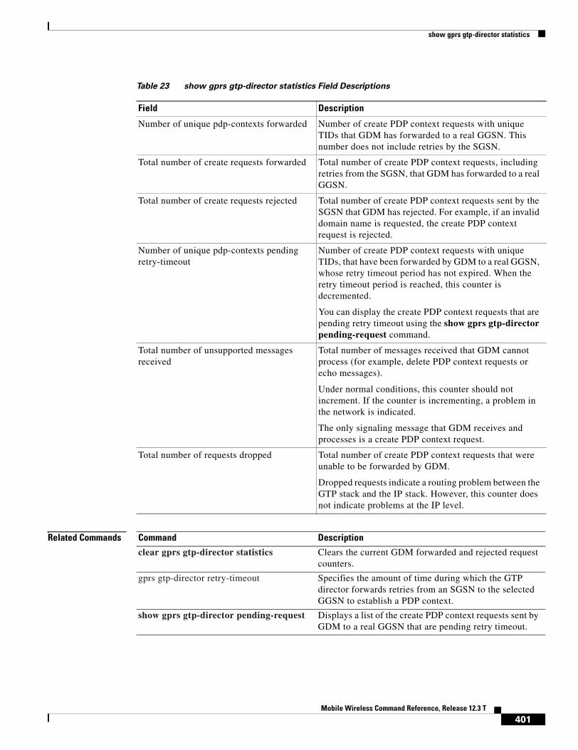
show gprs gtp-director statistics
Related Commands
Table 23 show gprs gtp-director statistics Field Descriptions
Field Description
Number of unique pdp-contexts forwarded Number of create PDP context requests with unique TIDs that GDM has forwarded to a real GGSN. This number does not include retries by the SGSN.
Total number of create requests forwarded Total number of create PDP context requests, including retries from the SGSN, that GDM has forwarded to a real GGSN.
Total number of create requests rejected Total number of create PDP context requests sent by the SGSN that GDM has rejected. For example, if an invalid domain name is requested, the create PDP context request is rejected.
Number of unique pdp-contexts pending retry-timeout
Number of create PDP context requests with unique TIDs, that have been forwarded by GDM to a real GGSN, whose retry timeout period has not expired. When the retry timeout period is reached, this counter is decremented.
You can display the create PDP context requests that are pending retry timeout using the show gprs gtp-director pending-request command.
Total number of unsupported messages received
Total number of messages received that GDM cannot process (for example, delete PDP context requests or echo messages).
Under normal conditions, this counter should not increment. If the counter is incrementing, a problem in the network is indicated.
The only signaling message that GDM receives and processes is a create PDP context request.
Total number of requests dropped Total number of create PDP context requests that were unable to be forwarded by GDM.
Dropped requests indicate a routing problem between the GTP stack and the IP stack. However, this counter does not indicate problems at the IP level.
Command Description
clear gprs gtp-director statistics Clears the current GDM forwarded and rejected request counters.
gprs gtp-director retry-timeout Specifies the amount of time during which the GTP director forwards retries from an SGSN to the selected GGSN to establish a PDP context.
show gprs gtp-director pending-request Displays a list of the create PDP context requests sent by GDM to a real GGSN that are pending retry timeout.
401Mobile Wireless Command Reference, Release 12.3 T

show gprs ms-address exclude-range
show gprs ms-address exclude-rangeTo display the IP address range(s) configured on the GGSN for the GPRS network, use the show gprs ms-address exclude-range privileged EXEC command.
show gprs ms-address exclude-range
Syntax Description This command has no arguments or keywords.
Defaults No default behavior or values.
Command Modes Privileged EXEC
Command History
Usage Guidelines Use the show gprs ms-address exclude-range command to display the IP address range(s) configured on the GGSN for the GPRS network.
IP addresses are 32-bit values.
Examples The following is sample output of the show gprs ms-address exclude-range command:
router# show gprs ms-address exclude-range Start IP End IP10.0.0.1 10.10.10.10
Table 24 describes the fields shown in the display.
Related Commands
Release Modification
12.2(4)MX This command was introduced.
12.2(8)YD This command was incorporated in Cisco IOS Release 12.2(8)YD.
12.2(8)B This command was incorporated in Cisco IOS Release 12.2(8)B.
12.3(4)T This command was incorporated in Cisco IOS Release 12.3(4)T.
12.3(8)T This command was incorporated in Cisco IOS Release 12.3(8)T.
Table 24 show gprs ms-address exclude-range Field Descriptions
Field Description
Start IP IP address at the beginning of the range.
End IP IP address at the end of the range.
Command Description
gprs ms-address exclude-range
Specifies the IP address range(s) used by the GPRS network and thereby excluded from the mobile station (MS) IP address range.
402Mobile Wireless Command Reference, Release 12.3 T

show gprs ms-address exclude-range
403Mobile Wireless Command Reference, Release 12.3 T

show gprs plmn ip address
show gprs plmn ip addressTo display the IP address range(s) configured for a PLMN, use the show gprs plmn ip address privileged EXEC command.
show gprs plmn ip address
Syntax Description This command has no arguments or keywords.
Defaults No default behavior or values.
Command Modes Privileged EXEC
Command History
Usage Guidelines Use the show gprs plmn ip address command to display the IP address range(s) configured for a PLMN.
IP addresses are 32-bit values.
Examples The following is sample output of the show gprs plmn ip address command:
router# show gprs plmn ip addressPLMN Start IP End IP Range Type9.9.9.9 9.9.9.9 10.2.25.1 10.2.25.255 16.0.0.9 16.0.0.9 99.100.0.1 99.100.0.255 101.0.1.1 101.0.1.1 sgsn105.0.1.1 105.0.1.1 sgsn106.0.1.1 106.0.1.1 sgsn110.12.0.2 110.12.0.2 110.13.0.2 110.13.0.2
Table 24 describes the fields shown in the display.
Release Modification
12.2(8)YW This command was introduced.
12.3(2)XB This command was incorporated in Cisco IOS Release 12.3(2)XB.
12.3(8)T This command was incorporated in Cisco IOS Release 12.3(8)T.
Table 25 show gprs plmn ip address Field Descriptions
Field Description
PLMN Start IP IP address at the beginning of the range.
End IP IP address at the end of the range.
404Mobile Wireless Command Reference, Release 12.3 T

show gprs plmn ip address
Related Commands Command Description
gprs plmn ip address Specifies the PLMN IP address range(s) used by the GGSN.
405Mobile Wireless Command Reference, Release 12.3 T

show gprs qos status
show gprs qos statusTo display the number of PDP contexts currently active on the GGSN for a particular QoS class, use the show gprs qos status privileged EXEC command.
show gprs qos status
Syntax Description This command has no arguments or keywords.
Defaults No default behavior or values.
Command Modes Privileged EXEC
Command History
Usage Guidelines Use the show gprs qos status command to display the number of PDP contexts currently active on the GGSN for a particular QoS class.
Examples Example 1
The following example shows output from the show gprs qos status command for UMTS QoS:
router# show gprs qos statusGPRS QoS Status: type:UMTS conversational_pdp 100 streaming_pdp 150 interactive_pdp 1345 background_pdp 2000
Release Modification
12.2(8)YW This command was introduced.
12.3(2)XB This command was incorporated in Cisco IOS Release 12.3(2)XB.
12.3(8)T This command was incorporated in Cisco IOS Release 12.3(8)T.
406Mobile Wireless Command Reference, Release 12.3 T

show gprs qos status
Table 26 describes the fields shown in the display.
Example 2
The following example displays output from the show gprs qos status command for canonical QoS:
router# show gprs qos statusGPRS QoS Status:type:Canonical gsn_used_bandwidth:1110.000 total gsn_resource:1048576 mean_throughput_premium:0.000 mean_throughput_normal:1110.000 mean_throughput_besteffort 0.000 qos_high_pdp:0 qos_normal_pdp:1 qos_low_pdp :0 qos_premium mean-throughput-deviation 0.100
Table 27 describes the fields shown in the display.
Table 26 show gprs qos status Field Descriptions
Field Description
type Type of QoS. Possible QoS types are:
• Canonical—Configured using the gprs qos map canonical-qos command.
• Delay—Configured using the gprs qos map delay command.
• UMTS—Configured using the gprs qos map umts command.
• None—No QoS is configured on the GGSN.
conversational_pdp Current number of PDP contexts that have a conversational UMTS QoS traffic class.
streaming_pdp Current number of PDP contexts that have a streaming UMTS QoS traffic class.
interactive_pdp Current number of PDP contexts that have a interactive UMTS QoS traffic class.
background_pdp Current number of PDP contexts that have a background UMTS QoS traffic class.
Table 27 show gprs qos status Field Descriptions
Field Description
type Type of QoS. Possible QoS types are:
• Canonical—Configured using the gprs qos map canonical-qos command.
• Delay—Configured using the gprs qos map delay command.
• UMTS—Configured using the gprs qos map umts command.
• None—No QoS is configured on the GGSN.
gsn_used_bandwidth Currently used bandwidth, in bits per second.
total gsn_resource Currently available GSN resources.
407Mobile Wireless Command Reference, Release 12.3 T
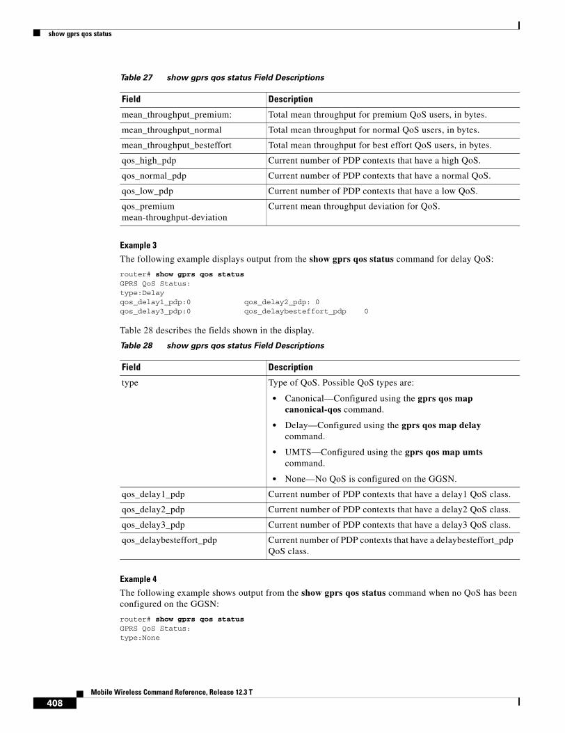
show gprs qos status
Example 3
The following example displays output from the show gprs qos status command for delay QoS:
router# show gprs qos statusGPRS QoS Status:type:Delay qos_delay1_pdp:0 qos_delay2_pdp: 0 qos_delay3_pdp:0 qos_delaybesteffort_pdp 0
Table 28 describes the fields shown in the display.
Example 4
The following example shows output from the show gprs qos status command when no QoS has been configured on the GGSN:
router# show gprs qos statusGPRS QoS Status:type:None
mean_throughput_premium: Total mean throughput for premium QoS users, in bytes.
mean_throughput_normal Total mean throughput for normal QoS users, in bytes.
mean_throughput_besteffort Total mean throughput for best effort QoS users, in bytes.
qos_high_pdp Current number of PDP contexts that have a high QoS.
qos_normal_pdp Current number of PDP contexts that have a normal QoS.
qos_low_pdp Current number of PDP contexts that have a low QoS.
qos_premium mean-throughput-deviation
Current mean throughput deviation for QoS.
Table 27 show gprs qos status Field Descriptions
Field Description
Table 28 show gprs qos status Field Descriptions
Field Description
type Type of QoS. Possible QoS types are:
• Canonical—Configured using the gprs qos map canonical-qos command.
• Delay—Configured using the gprs qos map delay command.
• UMTS—Configured using the gprs qos map umts command.
• None—No QoS is configured on the GGSN.
qos_delay1_pdp Current number of PDP contexts that have a delay1 QoS class.
qos_delay2_pdp Current number of PDP contexts that have a delay2 QoS class.
qos_delay3_pdp Current number of PDP contexts that have a delay3 QoS class.
qos_delaybesteffort_pdp Current number of PDP contexts that have a delaybesteffort_pdp QoS class.
408Mobile Wireless Command Reference, Release 12.3 T

show gprs qos status
Related Commands Command Description
gprs qos map canonical-qos
Enables mapping of GPRS QoS categories to a canonical QoS method that includes best-effort, normal, and premium QoS classes.
gprs qos map delay Enables Delay QoS on the GGSN.
gprs qos map umts Enables UMTS QoS on the GGSN.
409Mobile Wireless Command Reference, Release 12.3 T

show gprs umts-qos map traffic-class
show gprs umts-qos map traffic-classTo display UMTS QoS mapping information, use the show gprs umts-qos map traffic-class privileged EXEC command.
show gprs umts-qos map traffic-class {all | signalling | conversational | streaming | interactive | background}
Syntax Description
Defaults No default behavior or values.
Command Modes Privileged EXEC
Command History
Usage Guidelines Use the show gprs umts-qos map traffic-class command to display information about UMTS QoS mapping.
Examples The following example shows output from the show gprs umts-qos map traffic-class command for all UMTS QoS traffic classes:
router# show gprs umts-qos map traffic-class allTraffic Class Diffserv PHB Group Diffserv Code Point
signaling Signaling Class 40
conversational EF Class 46
streaming AF2 Class 18,20,22
interactive AF3 Class 26,28,30
background Best Effort 0
all Displays information for all UMTS QoS traffic classes.
signalling Displays information for the UMTS QoS traffic class signalling.
conversational Displays information for the UMTS QoS traffic class conversational.
streaming Displays information for the UMTS QoS traffic class streaming.
interactive Displays information for the UMTS QoS traffic class interactive.
background Displays information for the UMTS QoS traffic class background.
Release Modification
12.2(8)YW This command was introduced.
12.3(2)XB This command was incorporated in Cisco IOS Release 12.3(2)XB.
12.3(8)T This command was incorporated in Cisco IOS Release 12.3(8)T.
410Mobile Wireless Command Reference, Release 12.3 T

show gprs umts-qos map traffic-class
Table 29 describes the fields shown in the display.
Related Commands
Table 29 show gprs umts-qos map traffic-class Field Descriptions
Field Description
Traffic Class Type of UMTS QoS traffic class as specified in the gprs umts-qos map traffic-class command. The UMTS QoS traffic classes are:
• signaling
• conversational
• streaming
• interactive
• background
Diffserv PHB Group Type of DiffServ PHB group as specified in the gprs umts-qos map diffserv-phb command. Possible DiffServ PHB groups are:
• signalling-class
• ef-class
• af1-class
• af2-class
• af3-class
• af4-class
• best-effort
Diffserv Code Point Number of DSCPs as specified in the gprs umts-qos map diffserv-phb command.
Command Description
gprs umts-qos map traffic-class
Specifies a QoS mapping from the UMTS traffic classes to a differentiated services (DiffServ) per-hop behavior (PHB) group
gprs umts-qos map diffserv-phb
Assigns a differentiated services code point (DSCP) to a DiffServ PHB group.
411Mobile Wireless Command Reference, Release 12.3 T

show ip rtp header-compression
show ip rtp header-compressionTo display Enhanced Compressed Real-Time Transport Protocol (CRTP) statistics, use the show ip rtp header-compression command in privileged EXEC mode.
show ip rtp header-compression [detail] [interface-type interface-number]
Syntax Description
Defaults No default behavior or values
Command Modes Privileged EXEC
Command History
Usage Guidelines The detail keyword is not available with the show ip rtp header-compression command on a Route Switch Processor (RSP). However, the detail keyword is available with the show ip rtp header-compression command on a Versatile Interface Processor (VIP). Enter the show ip rtp header-compression interface-type interface-number detail command on a VIP to retrieve detailed information regarding RTP header compression on a specific interface.
The detail keyword is not supported with the show ip rtp header-compression command on the Cisco MWR 1941-DC router or the MGX-RPM-1FE-CP back card. If specified when the command is entered, the output does not display. Additionally, not all field descriptions displayed by the show ip rtp header-compression command are applicable to the MWR 1941-DC router and MGX-RPM-1FE-CP back card.
detail (Optional) Displays details of each connection.
interface-type interface-number
(Optional) The interface type and number.
Release Modification
11.3 This command was introduced.
12.1(5)T The command output was modified to include information related to the Distributed Compressed Real-Time Transport Protocol (dCRTP) feature.
12.3(11)T The command output was modified to include information related to the Enhanced Compressed Real-Time Transport Protocol (ECRTP) feature.
412Mobile Wireless Command Reference, Release 12.3 T

show ip rtp header-compression
Examples The following example displays statistics from ECRTP on an interface:
Router# show ip rtp header-compression
RTP/UDP/IP header compression statistics: Interface Serial2/0 (compression on, IETF, ECRTP) Rcvd: 1473 total, 1452 compressed, 0 errors, 0 status msgs 0 dropped, 0 buffer copies, 0 buffer failures Sent: 1234 total, 1216 compressed, 0 status msgs, 379 not predicted 41995 bytes saved, 24755 bytes sent 2.69 efficiency improvement factor Connect: 16 rx slots, 16 tx slots, 6 misses, 0 collisions, 0 negative cache hits, 13 free contexts 99% hit ratio, five minute miss rate 0 misses/sec, 0 max
Table 30 describes the significant fields shown in the display.
Table 30 show ip rtp header-compression Field Descriptions
Field Description
Interface Type and number of interface.
Rcvd Received statistics described in subsequent fields.
total Number of packets received on the interface.
compressed Number of packets received with compressed headers.
errors Number of errors.
status msgs Number of resynchronization messages received from the peer.
dropped Number of packets dropped.
buffer copies Number of buffers that were copied.
buffer failures Number of failures in allocating buffers.
Sent Sent statistics described in subsequent fields.
total Number of packets sent on the interface.
compressed Number of packets sent with compressed headers.
status msgs Number of resynchronization messages sent from the peer.
not predicted Number of packets taking a non-optimal path through the compressor.
bytes saved Total savings in bytes due to compression.
bytes sent Total bytes sent after compression.
efficiency improvement factor Compression efficiency.
Connect Connect statistics described in subsequent fields.
rx slots Total number of receive slots.
tx slots Total number of transmit slots.
misses Total number of misses.
collisions Total number of collisions.
negative cache hits Total number of negative cache hits.
free contexts Number of available context resources.
413Mobile Wireless Command Reference, Release 12.3 T

show ip rtp header-compression
Related Commands
hit ratio Percentage of received packets that have an associated context.
five minute miss rate Number of new flows found per second averaged over the last five minutes.
max Highest average rate of new flows reported.
Table 30 show ip rtp header-compression Field Descriptions (continued)
Field Description
Command Description
ip rtp compression-connections
Specifies the total number of RTP header compression connections supported on the interface.
ip rtp header-compression Enables RTP header compression.
414Mobile Wireless Command Reference, Release 12.3 T
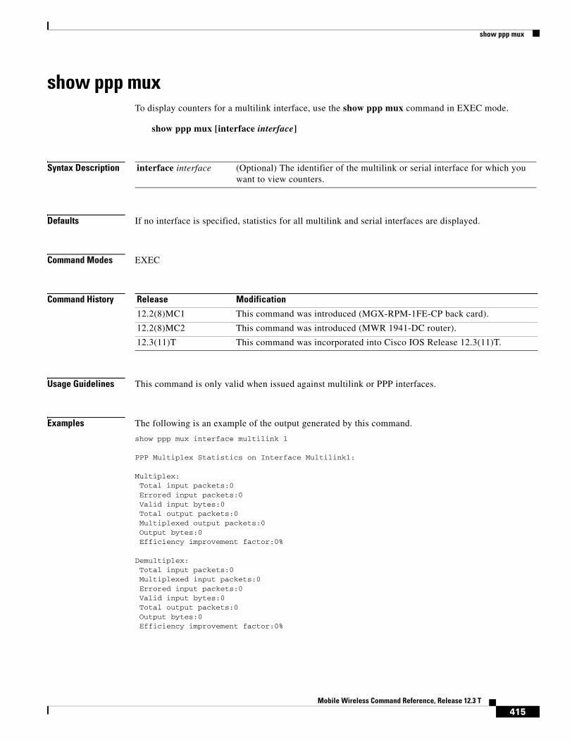
show ppp mux
show ppp muxTo display counters for a multilink interface, use the show ppp mux command in EXEC mode.
show ppp mux [interface interface]
Syntax Description
Defaults If no interface is specified, statistics for all multilink and serial interfaces are displayed.
Command Modes EXEC
Command History
Usage Guidelines This command is only valid when issued against multilink or PPP interfaces.
Examples The following is an example of the output generated by this command.
show ppp mux interface multilink 1
PPP Multiplex Statistics on Interface Multilink1:
Multiplex:Total input packets:0Errored input packets:0Valid input bytes:0Total output packets:0Multiplexed output packets:0Output bytes:0Efficiency improvement factor:0%
Demultiplex:Total input packets:0Multiplexed input packets:0Errored input packets:0Valid input bytes:0Total output packets:0Output bytes:0Efficiency improvement factor:0%
interface interface (Optional) The identifier of the multilink or serial interface for which you want to view counters.
Release Modification
12.2(8)MC1 This command was introduced (MGX-RPM-1FE-CP back card).
12.2(8)MC2 This command was introduced (MWR 1941-DC router).
12.3(11)T This command was incorporated into Cisco IOS Release 12.3(11)T.
415Mobile Wireless Command Reference, Release 12.3 T

show ppp mux
Table 31 describes the significant fields shown in the display.
The efficiency improvement factor is calculated as follows:
Multiplex efficiency improvement factor = 100 * (Total bytes saved) / (Total bytes received)
Where total bytes saved = bytes_received_at_muxer - bytes_sent_at_muxer.
Demultiplex efficiency improvement factor = 100 * (Total bytes saved) / (Total bytes sent)
Where total bytes saved = bytes_sent_at_demuxer - bytes_received_at_demuxer.
Related Commands
Table 31 show ppp mux Field Descriptions
Field Description
Total output packets Number of outbound packets
Multiplexed output packets Number of outbound multiplexed superframes
Output byte count Number of outbound bytes
Total input packets Number of inbound packets
Errored input packets Number of inbound packets discarded due to error
Efficiency improvement factor Percentage of efficiency improvement achieved through multiplexing or demultiplexing
Command Description
ppp mux Enables PPP multiplexing/demultiplexing
416Mobile Wireless Command Reference, Release 12.3 T

show radius local-server statistics
show radius local-server statisticsTo display the statistics for the local authentication server, use the show radius local-server statistics command in privileged EXEC mode.
show radius local-server statistics
Syntax Description This command has no arguments or keywords.
Command Modes Privileged EXEC
Command History
Examples The following output displays statistics for the local authentication server:
Router# show radius local-server statistics
Successes : 11262 Unknown usernames : 0Client blocks : 0 Invalid passwords : 8Unknown NAS : 0 Invalid packet from NAS: 0
NAS : 10.0.0.1Successes : 11262 Unknown usernames : 0Client blocks : 0 Invalid passwords : 8Corrupted packet : 0 Unknown RADIUS message : 0No username attribute : 0 Missing auth attribute : 0Shared key mismatch : 0 Invalid state attribute: 0Unknown EAP message : 0 Unknown EAP auth type : 0
Maximum number of configurable users: 50, current user count: 11Username Successes Failures Blocksvayu-ap-1 2235 0 0vayu-ap-2 2235 0 0vayu-ap-3 2246 0 0vayu-ap-4 2247 0 0vayu-ap-5 2247 0 0vayu-11 3 0 0vayu-12 5 0 0vayu-13 5 0 0vayu-14 30 0 0vayu-15 3 0 0scm-test 1 8 0
Release Modification
12.2(11)JA This command was introduced on Cisco Aironet Access Point 1100 and Cisco Aironet Access Point 1200.
12.3(11)T This command was implemented on the following platforms: Cisco 2600XM, Cisco 2691, Cisco 2811, Cisco 2821, Cisco 2851, Cisco 3700, and Cisco 3800 series routers.
417Mobile Wireless Command Reference, Release 12.3 T

show radius local-server statistics
Related Commands Command Description
block count Configures the parameters for locking out members of a group to help protect against unauthorized attacks.
clear radius local-server
Clears the statistics display or unblocks a user.
debug radius local-server
Displays the debug information for the local server.
group Enters user group configuration mode and configures shared setting for a user group.
nas Adds an access point or router to the list of devices that use the local authentication server.
radius-server host Specifies the remote RADIUS server host.
radius-server local Enables the access point or router to be a local authentication server and enters into configuration mode for the authenticator.
reauthentication time Specifies the time (in seconds) after which access points or wireless-aware routers must reauthenticate the members of a group.
ssid Specifies up to 20 SSIDs to be used by a user group.
user Authorizes a user to authenticate using the local authentication server.
vlan Specifies a VLAN to be used by members of a user group.
418Mobile Wireless Command Reference, Release 12.3 T

show tech-support cdma pdsn
show tech-support cdma pdsnTo display PDSN information that is useful to Cisco Customer Engineers for diagnosing problems, use the show tech-support cdma pdsn command in privileged EXEC mode.
show tech support cdma pdsn
Syntax Description This command has no arguments or keywords.
Defaults No default behavior or values.
Command Modes Privileged EXEC
Command History
Usage Guidelines This command displays the output of several show commands. We recommend that you attach the output of this command whenever you submit a PDSN problem report.
Examples The following example shows typical output of the show tech-support cdma pdsn command:
pdsn-6500#show tech-support cdma pdsn
------------------ show version ------------------
Cisco Internetwork Operating System Software IOS (tm) 6500 Software (C6500-C5IS-M), Experimental Version 12.2(20020306:074931) [user-dw91527 104]Copyright (c) 1986-2002 by cisco Systems, Inc.Compiled Wed 06-Mar-02 22:21 by userImage text-base:0x600088E0, data-base:0x6169A000
ROM:System Bootstrap, Version 12.0(19990210:195103) [12.0XE 105], DEVELOPMENT SOFTWAREBOOTLDR:6500 Software (C6500-BOOT-M), Version 12.0(3)T, RELEASE SOFTWARE (fc1)
mwt10-7206a uptime is 20 minutesSystem returned to ROM by reload at 23:17:59 UTC Wed Mar 6 2002System image file is "tftp://223.255.254.254/user/c6500-c5is-mz.dw91527"
cisco 7206VXR (NPE300) processor (revision D) with 229376K/65536K bytes of memory.Processor board ID 21302179R7000 CPU at 262Mhz, Implementation 39, Rev 2.1, 256KB L2, 2048KB L3 Cache6 slot VXR midplane, Version 2.1
Last reset from power-onBridging software.
Release Modification
12.1(3)XS This command was modified to include PDSN status.
12.3(4)T This command was incorporated in Cisco IOS Release 12.3(4)T.
419Mobile Wireless Command Reference, Release 12.3 T

show tech-support cdma pdsn
X.25 software, Version 3.0.0.8 Ethernet/IEEE 802.3 interface(s)1 FastEthernet/IEEE 802.3 interface(s)1 ATM network interface(s)125K bytes of non-volatile configuration memory.
8192K bytes of Flash PCMCIA card at slot 0 (Sector size 128K).4096K bytes of Flash internal SIMM (Sector size 256K).Configuration register is 0x0
------------------ show running-config ------------------
Building configuration...
Current configuration :3015 bytes!version 12.2no parser cacheno service padservice timestamps debug uptimeservice timestamps log uptimeno service password-encryptionservice cdma pdsn!hostname mwt10-7206a!aaa new-model!!aaa authentication login default noneaaa authentication ppp default group radiusaaa authentication ppp VPDN group radiusaaa authorization config-commandsaaa authorization ipmobile default group radius aaa authorization network default group radius aaa authorization network VPDN group radiusaaa authorization config-commandsaaa authorization network default group radius aaa authorization configuration default group radiusaaa accounting update periodic 10aaa accounting network pdsn start-stop group radiusaaa session-id commonenable secret 5 <removed>enable password <removed>!username abc password 0 <removed>ip subnet-zerono ip gratuitous-arpsip cefip cef accounting per-prefix non-recursive prefix-length!!!ip ftp source-interface Ethernet2/0no ip domain-lookup!vpdn enablevpdn authen-before-forwardvirtual-profile aaa!!!
420Mobile Wireless Command Reference, Release 12.3 T

show tech-support cdma pdsn
!!!!interface Loopback0 ip address 6.0.0.1 255.0.0.0!interface CDMA-Ix1 ip address 5.0.0.1 255.0.0.0 tunnel source 5.0.0.1 tunnel key 0 tunnel sequence-datagrams!interface FastEthernet1/0 ip address 4.0.0.101 255.0.0.0 duplex halfspeed autono cdp enable
!interface Ethernet2/0 ip address 7.0.0.1 255.0.0.0 no ip proxy-arp no ip route-cache no ip mroute-cache duplex half no cdp enable!interface Ethernet2/1 ip address 150.1.10.4 255.255.0.0 duplex half no cdp enable!interface Ethernet2/2 no ip address no ip mroute-cache shutdown duplex half no cdp enable!interface Ethernet2/3 no ip address no ip mroute-cache shutdown duplex half no cdp enable!interface Ethernet2/4 no ip address no ip mroute-cache shutdown duplex half no cdp enable!interface Ethernet2/5 no ip address no ip mroute-cache shutdown duplex half no cdp enable!interface Ethernet2/6 no ip address no ip mroute-cache shutdown
421Mobile Wireless Command Reference, Release 12.3 T

show tech-support cdma pdsn
duplex half no cdp enable!interface Ethernet2/7 no ip address no ip mroute-cache shutdown duplex half no cdp enable!interface ATM4/0 no ip address no ip mroute-cache shutdown no atm ilmi-keepalive!interface Virtual-Template1 ip unnumbered Loopback0 ip mobile foreign-service challenge ip mobile foreign-service reverse-tunnelip mobile registration-lifetime 65535
no peer default ip address ppp authentication chap pap optional!router mobile!ip local pool ispabc-pool1 9.0.0.1 9.0.0.255ip classlessip route 10.0.0.0 255.0.0.0 7.0.0.2no ip http serverip pim bidir-enableip mobile foreign-agent care-of Ethernet2/0ip mobile proxy-host nai [email protected] flags 42!!dialer-list 1 protocol ip permitdialer-list 1 protocol ipx permitno cdp run!!radius-server host 150.1.0.1 auth-port 1645 acct-port 1646 key <removed>radius-server retransmit 3radius-server optional-passwordsradius-server key <removed>radius-server vsa send accountingradius-server vsa send authenticationradius-server vsa send accounting 3gpp2radius-server vsa send authentication 3gpp2cdma pdsn virtual-template 1cdma pdsn a10 max-lifetime 65535cdma pdsn a10 ahdlc-engine 5 usable-channels 8000cdma pdsn timeout mobile-ip-registration 300cdma pdsn msid-authenticationcdma pdsn selection interface Ethernet2/0cdma pdsn secure pcf default spi 100 key ascii testcdma pdsn secure pcf 4.0.0.1 spi 100 key ascii testcdma pdsn secure pcf 4.0.0.1 spi 1000 key ascii ciscocdma pdsn secure cluster default spi 100 key ascii ciscocall rsvp-sync!!mgcp profile default!dial-peer cor custom
422Mobile Wireless Command Reference, Release 12.3 T

show tech-support cdma pdsn
!!!!gatekeeper shutdown!!line con 0 exec-timeout 0 0line aux 0line vty 0 4 password <removed>!!end
------------------ show cdma pdsn ------------------
PDSN software version 1.2, service is enabled
A11 registration-update timeout 1 sec, retransmissions 5 Mobile IP registration timeout 300 sec A10 maximum lifetime allowed 65535 sec GRE sequencing is on Maximum PCFs limit not set, maximum sessions limit not set SNMP failure history table size 100 MSID Authentication is enabled Network code digits for IMSI 5, MIN 6, IRM 4 Profile Password is cisco Ingress address filtering is disabled Sending Agent Adv in case of IPCP Address Negotiation is disabled Aging of idle users disabled
Number of pcfs connected 1 Number of sessions connected 1, Simple IP flows 0, Mobile IP flows 0, Proxy Mobile IP flows 1
------------------ show ip interface brief ------------------
Interface IP-Address OK? Method Status ProtocolFastEthernet1/0 4.0.0.101 YES NVRAM up up Ethernet2/0 7.0.0.1 YES manual up up Ethernet2/1 150.1.10.4 YES NVRAM up up Ethernet2/2 unassigned YES NVRAM administratively down down Ethernet2/3 unassigned YES NVRAM administratively down down Ethernet2/4 unassigned YES NVRAM administratively down down Ethernet2/5 unassigned YES NVRAM administratively down down Ethernet2/6 unassigned YES NVRAM administratively down down Ethernet2/7 unassigned YES NVRAM administratively down down ATM4/0 unassigned YES NVRAM administratively down down Loopback0 6.0.0.1 YES NVRAM up up CDMA-Ix1 5.0.0.1 YES NVRAM up up Virtual-Template1 6.0.0.1 YES unset down down Virtual-Access1 unassigned YES unset up up Mobile0 unassigned YES unset up up Tunnel0 unassigned YES unset up up Tunnel1 7.0.0.1 YES unset up up Virtual-Access2 unassigned YES unset down down
423Mobile Wireless Command Reference, Release 12.3 T

show tech-support cdma pdsn
Virtual-Access3 unassigned YES unset up up Virtual-Access3.1 6.0.0.1 YES unset up up
------------------ show ip route ------------------
Codes:C - connected, S - static, I - IGRP, R - RIP, M - mobile, B - BGP D - EIGRP, EX - EIGRP external, O - OSPF, IA - OSPF inter area N1 - OSPF NSSA external type 1, N2 - OSPF NSSA external type 2 E1 - OSPF external type 1, E2 - OSPF external type 2, E - EGP i - IS-IS, L1 - IS-IS level-1, L2 - IS-IS level-2, ia - IS-IS inter area * - candidate default, U - per-user static route, o - ODR P - periodic downloaded static route
Gateway of last resort is not set
C 4.0.0.0/8 is directly connected, FastEthernet1/0C 5.0.0.0/8 is directly connected, CDMA-Ix1C 6.0.0.0/8 is directly connected, Loopback0C 7.0.0.0/8 is directly connected, Ethernet2/0S 10.0.0.0/8 [1/0] via 7.0.0.2C 150.1.0.0/16 is directly connected, Ethernet2/1 30.0.0.0/32 is subnetted, 1 subnetsC 30.0.0.1 is directly connected, Virtual-Access3.1
------------------ show cdma pdsn session brief ------------------
MSID PCF IP Address PSI Age St Flows Interface11122000050031 4.0.0.1 1 00:19:57 ACT 1 Virtual-Access3.1
------------------ show cdma pdsn session ------------------
Mobile Station ID IMSI 11122000050031 PCF IP Address 4.0.0.1, PCF Session ID 1 A10 connection time 00:19:57, registration lifetime 1800 sec Number of A11 re-registrations 1, time since last registration 1193 sec Current Access network ID 0004-0000-01 Last airlink record received is Active Start, airlink is active GRE sequence number transmit 12, receive 12 Using interface Virtual-Access3.1, status ACT Using AHDLC engine on slot 5, channel ID 0 This session has 1 flow
Flow service Proxy-Mobile, NAI [email protected] Mobile Node IP address 30.0.0.1 Home Agent IP address 7.0.0.2 Packets in 0, bytes in 0 Packets out 0, bytes out 0
------------------ show cdma pdsn pcf brief ------------------
PCF IP Address Sessions Pkts In Pkts Out Bytes In Bytes Out4.0.0.1 1 0 12 0 396
------------------ show cdma pdsn pcf ------------------
PCF 4.0.0.1 has 1 session Received 0 pkts (0 bytes), sent 12 pkts (396 bytes)
424Mobile Wireless Command Reference, Release 12.3 T

show tech-support cdma pdsn
PCF Session ID 1, Mobile Station ID IMSI 11122000050031 A10 connection age 00:19:58 A10 registration lifetime 1800 sec, time since last registration 1194 sec
------------------ show cdma pdsn selection summary ------------------
CDMA PDSN selection summary: Hostname PDSN Session-count Max-sessions *mwt10-7206a 5.0.0.1 1 8000 mwt10-7206b 12.0.0.1 0 8000
Hostname Keepalive Interface Load-factor *mwt10-7206a 30 7.0.0.1 0.00 mwt10-7206b 30 7.0.0.2 0.00
------------------ show ip mobile traffic ------------------
IP Mobility traffic:Advertisements: Solicitations received 0 Advertisements sent 0, response to solicitation 0Home Agent Registrations: Register 0, Deregister 0 requests Register 0, Deregister 0 replied Accepted 0, No simultaneous bindings 0 Denied 0, Ignored 0 , Dropped 0 Unspecified 0, Unknown HA 0 Administrative prohibited 0, No resource 0 Authentication failed MN 0, FA 0, active HA 0 Bad identification 0, Bad request form 0 Unavailable encap 0, reverse tunnel 0 Reverse tunnel mandatory 0 Binding Updates received 0, sent 0 total 0 fail 0 Binding Update acks received 0 sent 0 Binding info requests received 0, sent 0 total 0 fail 0 Binding info reply received 0 drop 0, sent 0 total 0 fail 0 Binding info reply acks received 0 drop 0, sent 0 Gratuitous 0, Proxy 0 ARPs sent Route Optimization Binding Updates sent 0, acks received 0 neg acks received 0 Unrecognized VendorID or CVSE-Type in CVSE sent by MN to HA 0 Unrecognized VendorID or CVSE-Type in CVSE sent by FA to HA 0Foreign Agent Registrations: Request in 0, Forwarded 0, Denied 0, Ignored 0 Unspecified 0, HA unreachable 0 Administrative prohibited 0, No resource 0 Bad lifetime 0, Bad request form 0 Unavailable encapsulation 0, Compression 0 Unavailable reverse tunnel 0 Reverse tunnel mandatory 0 Replies in 1 Forwarded 0, Bad 0, Ignored 1 Authentication failed MN 0, HA 0 Received challenge/gen. authentication extension, feature not enabled 0 Route Optimization Binding Updates received 0, acks sent 0 neg acks sent 0 Unknown challenge 0, Missing challenge 0, Stale challenge 0 Unrecognized VendorID or CVSE-Type in CVSE sent by MN to FA 0 Unrecognized VendorID or CVSE-Type in CVSE sent by HA to FA 0
------------------ show ip mobile globals ------------------
425Mobile Wireless Command Reference, Release 12.3 T

show tech-support cdma pdsn
IP Mobility global information:Home Agent is not enabled
Foreign Agent
Pending registrations expire after 15 secs Care-of addresses advertised Ethernet2/0 (7.0.0.1) - up
0 interfaces providing serviceEncapsulations supported:IPIP and GRETunnel fast switching enabledTunnel path MTU discovery aged out after 10 min
------------------ show ip mobile interface ------------------
IP Mobility interface information:
------------------ show vpdn tunnel ------------------
------------------ show cdma pdsn resource ------------------
Resource allocated/available in the resource manager
slot 0: AHDLC Engine Type:CDMA HDLC SW ENGINE Engine is ENABLED total channels:16000, available channels:16000
426Mobile Wireless Command Reference, Release 12.3 T

show wlccp wds
show wlccp wdsTo display information about the wireless domain services (WDS) device or information about client devices, use the show wlccp wds command in privileged EXEC mode.
show wlccp wds [ap | mn] [detail] [mac-addr mac-address]
Syntax Description
Defaults If you do not enter any options with the show wlccp wds command, this command displays the IP address of the WDS device, the MAC address, the priority, and the interface state. If the interface state is backup, the command also displays the IP address of the current WDS device, the MAC address, and the priority.
Command Modes Privileged EXEC
Command History
Usage Guidelines To show information about the WDS device, do not enter any keywords with this command.
Examples The following command entry displays information about the WDS device:
show wlccp wds ap
The following command entry displays cached information, including details, about the client device with the specified MAC address:
show wlccp wds mn detail mac-addr 00-05-C2-00-01-F5
The following is sample output from the show wlccp wds command:
Router# show wlccp wds
ap (Optional) Displays access points participating in Cisco Centralized Key Management (CCKM).
mn (Optional) Displays cached information about client devices, also called mobile nodes.
detail (Optional) Displays the lifetime of the client, the service set identifier (SSID), and the virtual LAN (VLAN) ID.
mac-addr (Optional) Displays information about a specific client device.
mac-address Client’s MAC address.
Release Modification
12.2(11)JA This command was introduced.
12.3(11)T This command was implemented on the following platforms: Cisco 2600XM, Cisco 2691, Cisco 2811, Cisco 2821, Cisco 2851, Cisco 3700, and Cisco 3800 series routers.
427Mobile Wireless Command Reference, Release 12.3 T

show wlccp wds
MAC:0001.28e0.a400, IP-ADDR:10.0.0.1 , Priority:255 Interface Vlan1, State:Administratively StandAlone - ACTIVE AP Count:1 , MN Count:0 , MAX AP Count:50
The following table describes the significant fields shown in the display.
Related Commands
Field Description
MAC MAC address of the interface on which the WDS is configured.
IP-Addr IP address of the interface on which the WDS is configured.
Priority Priority of the WDS.
Interface Interface on which the WDS is configured.
State State of the WDS. The state can be INITIALIZATION/BACKUP/ACTIVE/.
AP Count Number of access points registered to the WDS.
MN Count Number of mobile nodes registered to the WDS.
MAX AP Count Maximum number of access points that can be registered.
Command Description
debug wlccp packet Displays packet traffic to and from the WDS router.
debug wlccp wds Displays either WDS debug state or WDS statistics messages.
wlccp authentication-server client
Configures the list of servers to be used for 802.1X authentication.
wlccp authentication-server infrastructure
Configures the list of servers to be used for 802.1X authentication for the wireless infrastructure devices.
wlccp wds priority interface
Enables a wireless device such as an access point or a wireless-aware router to be a WDS candidate.
428Mobile Wireless Command Reference, Release 12.3 T

snmp-server enable traps cdma
snmp-server enable traps cdmaTo enable network management traps for CDMA, use the snmp-server enable traps cdma command in global configuration mode. To disable network management traps for CDMA, use the no form of this command.
snmp-server enable traps cdma
no snmp-server enable traps cdma
Syntax Description This command has no arguments or keywords.
Defaults Network management traps disabled.
Command Modes Global Configuration
Command History
Examples The following example enables network management traps for CDMA:
snmp-server enable traps cdma
Release Modification
12.1(3)XS This command was introduced.
12.3(4)T This command was incorporated in Cisco IOS Release 12.3(4)T.
429Mobile Wireless Command Reference, Release 12.3 T

ssid
ssidTo enter up to 20 service set identifiers (SSIDs) to a user group, use the ssid command in local RADIUS server group configuration mode. To instruct the access point (AP) not to check if the client has come in on a list of specified SSIDs, use the no form of this command.
ssid ssid-number
no ssid ssid-number
Syntax Description
Defaults No default behavior or values
Command Modes Local RADIUS server group configuration
Command History
Usage Guidelines You can enter up to 20 SSIDs to limit users to those SSIDs.
Examples The following example shows that the SSID “green” has been added to the local user group:
ssid green
Related Commands
ssid-number SSID number of user group members.
Release Modification
12.2(11)JA This command was introduced on Cisco Aironet Access Point 1100 and Cisco Aironet Access Point 1200.
12.3(11)T This command was implemented on the following platforms: Cisco 2600XM, Cisco 2691, Cisco 2811, Cisco 2821, Cisco 2851, Cisco 3700, and Cisco 3800 series routers.
Command Description
block count Configures the parameters for locking out members of a group to help protect against unauthorized attacks.
clear radius local-server
Clears the statistics display or unblocks a user.
debug radius local-server
Displays the debug information for the local server.
group Enters user group configuration mode and configures shared setting for a user group.
nas Adds an access point or router to the list of devices that use the local authentication server.
430Mobile Wireless Command Reference, Release 12.3 T
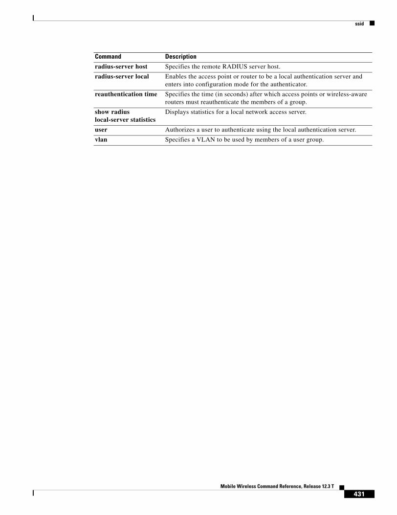
ssid
radius-server host Specifies the remote RADIUS server host.
radius-server local Enables the access point or router to be a local authentication server and enters into configuration mode for the authenticator.
reauthentication time Specifies the time (in seconds) after which access points or wireless-aware routers must reauthenticate the members of a group.
show radius local-server statistics
Displays statistics for a local network access server.
user Authorizes a user to authenticate using the local authentication server.
vlan Specifies a VLAN to be used by members of a user group.
Command Description
431Mobile Wireless Command Reference, Release 12.3 T

standalone
standaloneTo specify that the MWR 1941-DC is being used in a stand-alone configuration (which impacts the relays on the VWIC), use the standalone command. To use the MWR 1941-DC in a redundant configuration, use the no form of this command.
[no] standalone
Syntax Description This command has no attributes.
Defaults By default, the MWR 1941-DC is configured to be used in a redundant configuration (no standalone) and the relays are open.
Command Modes Y-cable configuration
Command History
Usage Guidelines Issuing the standalone command closes the relays on the VWICs installed in the MWR 1941-DC.
Examples The following example closes the relays so that the MWR 1941-DC can be used as a stand-alone device.
standalone
Related Commands
Release Modification
12.2(8)MC2 This command was introduced.
12.3(11)T This command was incorporated in Cisco IOS Release 12.3(11)T.
Command Description
mode y-cable Invokes y-cable mode.
standby use-interface Specifies the interfaces to be used for health and revertive interfaces.
432Mobile Wireless Command Reference, Release 12.3 T

standby use-interface
standby use-interfaceTo designate a loopback interface as a health or revertive interface, use the standby use-interface command.
standby use-interface interface {health | revertive | backhaul}
Syntax Description
Defaults By default, the MWR 1941-DC is configured to be used in a redundant configuration (no standalone) and the relays are open.
Command Modes Y-cable configuration
Command History
Usage Guidelines The loopback interfaces that you specify for health and revertive interfaces must be the same loopback interfaces that you specified in the standby track command. In the standby track command, the decrement value for the revertive interface should always be less than that for other interfaces. We recommend that you use loopback101 for health and loopback102 for revertive.
The interface that you specify for the backhaul must be an MLPPP interface. If you want to use a serial interface as the backhaul, you must first configure that interface to be part of an MLPPP bundle. We recommend you use multilink1 for the backhaul interface.
interface Indicates the interface to be used with the specified parameter. For health and revertive, this is the loopback interface specified in the standby track command. For backhaul, the interface must be an MLPPP interface. If you want to use a serial interface as the backhaul, you must first configure that interface to be part of an MLPPP bundle.
health Indicates the interface to monitor for an over temperature condition, the state of the processor, and the state of the T1/E1 firmware. If any of these watched conditions indicate a failure, this interface is brought down. Otherwise, the health interface remains in the up state.
revertive Indicates the interface that acts as the revertive interface. If the MWR 1941-DC router changes state from active to standby, the revertive interface is brought up. If the MWR 1941-DC router changes state from standby to active, the revertive interface is brought down.
backhaul Indicates the interface to be used for backhauling.
Release Modification
12.2(8)MC2 This command was introduced.
12.3(11)T This command was incorporated in Cisco IOS Release 12.3(11)T.
433Mobile Wireless Command Reference, Release 12.3 T

standby use-interface
Examples The following example specifies loopback101 as the health interface and loopback102 as the revertive interface.
standby use-interface loopback101 healthstandby use-interface loopback102 revertivestandby use-interface multilink1 backhaul
Related Commands Command Description
mode y-cable Invokes y-cable mode.
redundancy Invokes redundancy mode.
standalone Specifies whether the MWR 1941-DC router is used in a redundant or stand-alone configuration.
standby Sets HSRP attributes
434Mobile Wireless Command Reference, Release 12.3 T

subscription-required
subscription-requiredTo specify that the GGSN checks the value of the selection mode in a PDP context request to determine if a subscription is required to access a PDN through a particular access point, use the subscription-required access-point configuration command. To specify that no subscription is required, use the no form of this command.
subscription-required
no subscription-required
Defaults No subscription is required
Command Modes Access-point configuration.
Command History
Usage Guidelines Use the subscription-required command to specify that the GGSN checks the value of the selection mode in a PDP context request to determine if a subscription is required for user access to PDNs through the current access point. When you configure the subscription-required command at the APN, the GGSN looks for the “subscription verified” selection mode in the PDP context request to establish the session. If the GGSN finds that the selection mode is designated as subscription not verified in the PDP context request, then the GGSN rejects the PDP context request.
The subscription must be set up by the service provider, and subscription information must be passed with the mobile user’s PDP context requests.
Examples The following example specifies that the GGSN checks for subscription verification in the selection mode before establishing a session at the access-point:
access-point 1access-point-name gprs.somewhere.comdhcp-server 10.100.0.3 dhcp-gateway-address 10.88.0.1subscription-requiredexit
Release Modification
12.1(1)GA This command was introduced.
12.1(5)T This command was integrated in Cisco IOS Release 12.1(5)T.
12.2(4)MX This command was incorporated in Cisco IOS Release 12.2(4)MX.
12.2(8)YD This command was incorporated in Cisco IOS Release 12.2(8)YD.
12.2(8)B This command was incorporated in Cisco IOS Release 12.2(8)B.
12.3(4)T This command was incorporated in Cisco IOS Release 12.3(4)T.
12.3(8)T This command was incorporated in Cisco IOS Release 12.3(8)T.
435Mobile Wireless Command Reference, Release 12.3 T

user
userTo enter the names of users that are allowed to authenticate using the local authentication server, use the user command in local RADIUS server configuration mode. To remove the user name and password from the local RADIUS server, use the no form of this command.
user username {password | nthash} password [group group-name]
no user username {password | nthash} password [group group-name]
Syntax Description
Defaults If no group name is entered, the user is not assigned to a virtual LAN (VLAN) and is never required to reauthenticate.
Command Modes Local RADIUS server configuration
Command History
Usage Guidelines If you do not know the user password, look up the NT value of the password in the authentication server database, and enter the NT hash as a hexadecimal string.
Examples The following example shows that user “ssmith” has been allowed to authenticate using the local authentication server (using the password “smithisok”). The user will be added to the group “team1”:
user ssmith password smithisok group team1
username Name of the user that is allowed to authenticate using the local authentication server.
password Indicates that the user password will be entered.
nthash Indicates that the NT value of the password will be entered.
password User password.
group group-name (Optional) Name of group to which the user will be added.
Release Modification
12.2(11)JA This command was introduced on Cisco Aironet Access Point 1100 and Cisco Aironet Access Point 1200.
12.3(11)T This command was implemented on the following platforms: Cisco 2600XM, Cisco 2691, Cisco 2811, Cisco 2821, Cisco 2851, Cisco 3700, and Cisco 3800 series routers.
436Mobile Wireless Command Reference, Release 12.3 T

user
Related Commands Command Description
block count Configures the parameters for locking out members of a group to help protect against unauthorized attacks.
clear radius local-server
Clears the statistics display or unblocks a user.
debug radius local-server
Displays the debug information for the local server.
group Enters user group configuration mode and configures shared setting for a user group.
nas Adds an access point or router to the list of devices that use the local authentication server.
radius-server host Specifies the remote RADIUS server host.
radius-server local Enables the access point or router to be a local authentication server and enters into configuration mode for the authenticator.
reauthentication time Specifies the time (in seconds) after which access points or wireless-aware routers must reauthenticate the members of a group.
show radius local-server statistics
Displays statistics for a local network access server.
ssid Specifies up to 20 SSIDs to be used by a user group.
vlan Specifies a VLAN to be used by members of a user group.
437Mobile Wireless Command Reference, Release 12.3 T

vlan
vlanTo specify a virtual LAN (VLAN) to be used by members of the user group, use the vlan command in local RADIUS server group configuration mode. To reset the parameter to the default value, use the no form of the command.
vlan vlan
no vlan vlan
Syntax Description
Defaults No default behavior or values
Command Modes Local RADIUS server group configuration
Command History
Usage Guidelines The access point or router moves group members into the VLAN that you specify, overriding any other VLAN assignments. You can assign only one VLAN to a user group.
Examples The following example shows that VLAN “225” is to be used by members of the user group:
vlan 225
Related Commands
vlan VLAN ID.
Release Modification
12.2(11)JA This command was introduced on Cisco Aironet Access Point 1100 and Cisco Aironet Access Point 1200.
12.3(11)T This command was implemented on the following platforms: Cisco 2600XM, Cisco 2691, Cisco 2811, Cisco 2821, Cisco 2851, Cisco 3700, and Cisco 3800 series routers.
Command Description
block count Configures the parameters for locking out members of a group to help protect against unauthorized attacks.
clear radius local-server
Clears the statistics display or unblocks a user.
debug radius local-server
Displays the debug information for the local server.
group Enters user group configuration mode and configures shared setting for a user group.
438Mobile Wireless Command Reference, Release 12.3 T

vlan
nas Adds an access point or router to the list of devices that use the local authentication server.
radius-server host Specifies the remote RADIUS server host.
radius-server local Enables the access point or router to be a local authentication server and enters into configuration mode for the authenticator.
reauthentication time Specifies the time (in seconds) after which access points or wireless-aware routers must reauthenticate the members of a group.
show radius local-server statistics
Displays statistics for a local network access server.
ssid Specifies up to 20 SSIDs to be used by a user group.
user Authorizes a user to authenticate using the local authentication server.
Command Description
439Mobile Wireless Command Reference, Release 12.3 T

vrf (access-point configuration)
vrf (access-point configuration)To configure VPN routing and forwarding at a GGSN access point and associate the access point with a particular VRF instance, use the vrf command in access-point configuration mode.
vrf vrf-name
Syntax Description
Defaults No default behavior or values.
Command Modes Access-point configuration
Command History
Usage Guidelines Use the vrf command to configure VPN routing and forwarding (VRF) at a GGSN access point and associate the access point with a particular VRF instance. The vrf-name should match the name configured in an ip vrf global configuration command, and also the ip vrf forwarding command at the Gi interface.
To support VRF, you must also enable Cisco Express Forwarding (CEF) switching on the router using the ip cef global configuration command.
If you are also configuring DHCP services at the APN, then you must also configure the dhcp-server ip-address vrf command.
Note Memory constraints might occur if you define a large number of access points to support VPN Routing and Forwarding (VRF).
Examples The following example shows a VRF configuration for vpn3 (without tunneling) using the ip vrf global configuration command. Because the ip vrf command establishes both VRF and CEF routing tables, notice that ip cef also is configured at the global configuration level to enable CEF switching at all of the interfaces.
The following other configuration elements must also associate the same VRF named vpn3:
• FastEthernet0/0 is configured as the Gi interface using the ip vrf forwarding interface configuration command.
vrf-name Name of the corresponding VRF instance with which the access point is associated.
Release Modification
12.2(4)MX This command was introduced.
12.2(8)YD This command was integrated into Cisco IOS Release 12.2(8)YD.
12.2(8)B This command was integrated into Cisco IOS Release 12.2(8)B.
12.3(4)T This command was integrated into Cisco IOS Release 12.3(4)T.
440Mobile Wireless Command Reference, Release 12.3 T

vrf (access-point configuration)
• Access-point 2 implements VRF using the vrf command access-point configuration command.
The DHCP server at access-point 2 also is configured to support VRF. Notice that access-point 1 uses the same DHCP server, but is not supporting the VRF address space. The IP addresses for access-point 1 will apply to the global routing table:
aaa new-model!aaa group server radius fooserver 10.2.3.4server 10.6.7.8
!aaa authentication ppp foo group fooaaa authorization network default group radius aaa accounting exec default start-stop group foo!ip cef!ip vrf vpn3rd 300:3
!interface Loopback1ip address 10.30.30.30 255.255.255.255
!interface Loopback2ip vrf forwarding vpn3ip address 10.27.27.27 255.255.255.255
!interface FastEthernet0/0ip vrf forwarding vpn3ip address 10.50.0.1 255.255.0.0duplex half
!interface FastEthernet1/0ip address 10.70.0.1 255.255.0.0duplex half
!interface Virtual-Template1ip address 10.8.0.1 255.255.0.0encapsulation gtpgprs access-point-list gprs
!ip route 10.10.0.1 255.255.255.255 Virtual-Template1ip route vrf vpn3 10.100.0.5 255.255.255.0 fa0/0 10.50.0.2ip route 10.200.0.5 255.255.255.0 fa1/0 10.70.0.2!no ip http server!gprs access-point-list gprsaccess-point 1access-point-name gprs.pdn.comip-address-pool dhcp-proxy-clientdhcp-server 10.200.0.5dhcp-gateway-address 10.30.30.30 network-request-activationexit!
access-point 2access-point-name gprs.pdn2.comaccess-mode non-transparentip-address-pool dhcp-proxy-clientdhcp-server 10.100.0.5 10.100.0.6 vrfdhcp-gateway-address 10.27.27.27aaa-group authentication foo
441Mobile Wireless Command Reference, Release 12.3 T

vrf (access-point configuration)
vrf vpn3exit
!gprs default ip-address-pool dhcp-proxy-clientgprs gtp ip udp ignore checksum!radius-server host 10.2.3.4 auth-port 1645 acct-port 1646 non-standardradius-server host 10.6.7.8 auth-port 1645 acct-port 1646 non-standardradius-server key ggsntel
Related Commands Command Description
dhcp-server Specifies a primary (and backup) DHCP server to allocate IP addresses to MS users entering a particular PDN access point.
ip cef Enables CEF on the RP card.
ip vrf Configures a VRF routing table.
ip vrf forwarding Associates a VRF with an interface or subinterface.
rd Creates routing and forwarding tables for a VRF and and specifies the default route distinguisher for a VPN.
442Mobile Wireless Command Reference, Release 12.3 T
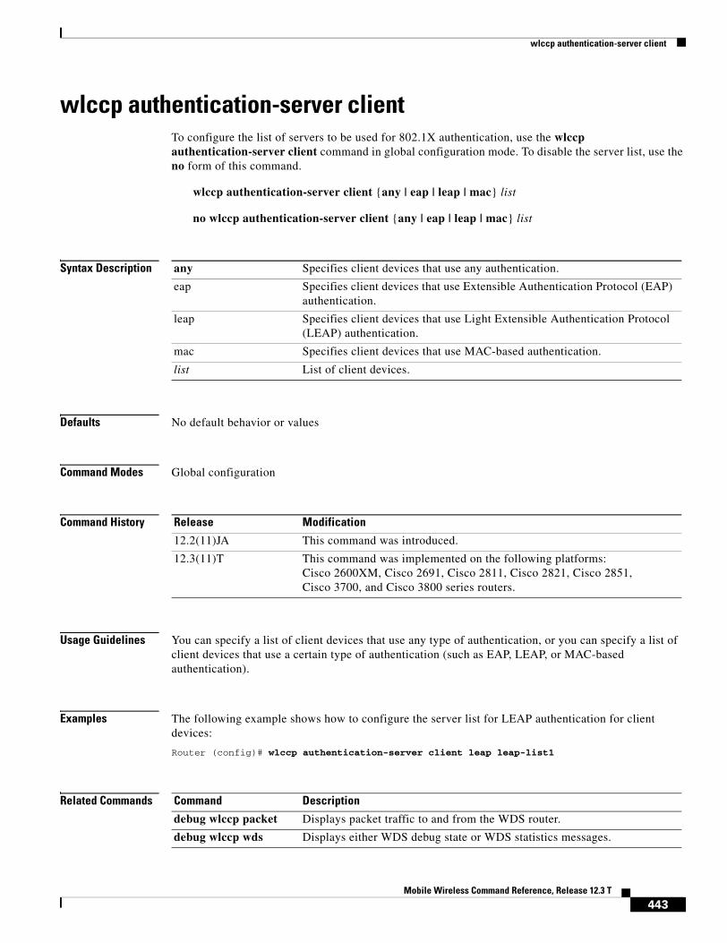
wlccp authentication-server client
wlccp authentication-server clientTo configure the list of servers to be used for 802.1X authentication, use the wlccp authentication-server client command in global configuration mode. To disable the server list, use the no form of this command.
wlccp authentication-server client {any | eap | leap | mac} list
no wlccp authentication-server client {any | eap | leap | mac} list
Syntax Description
Defaults No default behavior or values
Command Modes Global configuration
Command History
Usage Guidelines You can specify a list of client devices that use any type of authentication, or you can specify a list of client devices that use a certain type of authentication (such as EAP, LEAP, or MAC-based authentication).
Examples The following example shows how to configure the server list for LEAP authentication for client devices:
Router (config)# wlccp authentication-server client leap leap-list1
Related Commands
any Specifies client devices that use any authentication.
eap Specifies client devices that use Extensible Authentication Protocol (EAP) authentication.
leap Specifies client devices that use Light Extensible Authentication Protocol (LEAP) authentication.
mac Specifies client devices that use MAC-based authentication.
list List of client devices.
Release Modification
12.2(11)JA This command was introduced.
12.3(11)T This command was implemented on the following platforms: Cisco 2600XM, Cisco 2691, Cisco 2811, Cisco 2821, Cisco 2851, Cisco 3700, and Cisco 3800 series routers.
Command Description
debug wlccp packet Displays packet traffic to and from the WDS router.
debug wlccp wds Displays either WDS debug state or WDS statistics messages.
443Mobile Wireless Command Reference, Release 12.3 T

wlccp authentication-server client
show wlccp wds Shows information about access points and client devices on the WDS router.
wlccp authentication-server infrastructure
Configures the list of servers to be used for 802.1X authentication for the wireless infrastructure devices.
wlccp wds priority interface
Enables a wireless device such as an access point or a wireless-aware router to be a WDS candidate.
Command Description
444Mobile Wireless Command Reference, Release 12.3 T

wlccp authentication-server infrastructure
wlccp authentication-server infrastructureTo configure the list of servers to be used for 802.1X authentication for the wireless infrastructure devices, use the wlccp authentication-server infrastructure command in global configuration mode. To disable the server list, use the no form of this command.
wlccp authentication-server infrastructure list
no wlccp authentication-server infrastructure list
Syntax Description
Defaults No default behavior or values
Command Modes Global configuration
Command History
Examples This example shows how to configure the server list for 802.1X authentication for infrastructure devices participating in Cisco Centralized Key Management (CCKM):
Router (config)# wlccp authentication-server infrastructure wlan-list1
Related Commands
list List of servers to be used for 802.1X authentication for the wireless infrastructure devices, such as access points, repeaters, and wireless-aware routers.
Release Modification
12.2(11)JA This command was introduced on Cisco Aironet access points.
12.3(11)T This command was implemented on the following platforms: Cisco 2600XM, Cisco 2691, Cisco 2811, Cisco 2821, Cisco 2851, Cisco 3700, and Cisco 3800 series routers.
Command Description
debug wlccp packet Displays packet traffic to and from the WDS router.
debug wlccp wds Displays either WDS debug state or WDS statistics messages.
show wlccp wds Shows information about access points and client devices on the WDS router.
wlccp authentication-server client
Configures the list of servers to be used for 802.1X authentication.
wlccp wds priority interface
Enables a wireless device such as an access point or a wireless-aware router to be a WDS candidate.
445Mobile Wireless Command Reference, Release 12.3 T

wlccp wds priority interface
wlccp wds priority interfaceTo configure the router or access point to provide WDS, use the wlccp wds priority interface command in global configuration mode. To remove the WDS configuration from the router or access point, use the no form of the command .
wlccp wds priority priority interface interface
no wlccp wds priority priority interface interface
Syntax Description
Defaults No default behavior or values
Command Modes Global configuration
Command History
Usage Guidelines The WDS candidate with the highest priority becomes the active WDS device.
Examples This example shows how to configure the priority for an access point as a candidate to provide WDS with priority 200:
Router (config)# wlccp wds priority 200 interface bvi 1
Related Commands
priority Priority of this WDS candidate. The valid range is from 1 to 255. The greater the priority value, the higher the priority.
interface Interface on which the router sends out WDS advertisements. Supported interface types are as follows:
• For access points—bvi
• For wireless-aware routers—bvi, svi, Fast Ethernet, and Gigabit Ethernet.
Release Modification
12.2(11)JA This command was introduced with support for Cisco Aironet access points.
12.3(11T This command was implemented on the following platforms: Cisco 2600XM, Cisco 2691, Cisco 2811, Cisco 2821, Cisco 2851, Cisco 3700, and Cisco 3800 series routers.
Command Description
debug wlccp packet Displays packet traffic to and from the WDS router.
debug wlccp wds Displays either WDS debug state or WDS statistics messages.
show wlccp wds Shows information about access points and client devices on the WDS router.
446Mobile Wireless Command Reference, Release 12.3 T

wlccp wds priority interface
wlccp authentication-server client
Configures the list of servers to be used for 802.1X authentication.
wlccp authentication-server infrastructure
Configures the list of servers to be used for 802.1X authentication for the wireless infrastructure devices.
Command Description
447Mobile Wireless Command Reference, Release 12.3 T

wlccp wds priority interface
448Mobile Wireless Command Reference, Release 12.3 T

Appendix A: SGSN D-Node Commands
The commands in this section are for certain operator-specific, SGSN D-node implementations only. These commands are not to be used for any other type of standard, SGSN-related configuration, or to configure any GGSN services.
449Mobile Wireless Command Reference, Release 12.3 T

Appendix A: SGSN D-Node Commandsclear gprs isgsn statistics
clear gprs isgsn statisticsTo clear the current GPRS intra-Serving GPRS Support Node (iSGSN) statistics, use the clear gprs isgsn statistics privileged EXEC command (SGSN D-node only).
clear gprs isgsn statistics
Syntax Description This command has no arguments or keywords.
Defaults No default behavior or values.
Command Modes Privileged EXEC
Command History
Usage Guidelines Use the clear gprs isgsn statistics command to clear the current GPRS iSGSN statistics. This command clears the counters that are displayed by the show gprs isgsn statistics command.
Examples The following example clears the current GPRS iSGSN statistics:
router# clear gprs isgsn statistics
Release Modification
12.1(1)GA This command was introduced.
12.1(3)T This command was integrated in Cisco IOS Release 12.1(3)T.
450Mobile Wireless Command Reference, Release 12.3 T

Appendix A: SGSN D-Node Commandsclear l2relay statistics
clear l2relay statisticsTo clear the Layer 2 Relay (l2relay) statistics for the SGSN, use the clear l2relay statistics privileged EXEC command (SGSN D-node only).
clear l2relay statistics
Syntax Description This command has no arguments or keywords.
Defaults No default behavior or values.
Command Modes Privileged EXEC
Command History
Usage Guidelines Use the clear l2relay statistics command to clear the current l2relay statistics.
Examples The following example clears the l2relay statistics:
router# clear l2relay statistics
Related Commands
Release Modification
12.1(1)GA This command was introduced.
12.1(3)T This command was integrated in Cisco IOS Release 12.1(3)T.
Command Description
clear l2relay topology-map
Clears the Layer 2 Relay topology map for the SGSN.
451Mobile Wireless Command Reference, Release 12.3 T

Appendix A: SGSN D-Node Commandsclear l2relay topology-map
clear l2relay topology-mapTo clear the Layer 2 Relay topology map for the SGSN, use the clear l2relay topology-map privileged EXEC command (SGSN D-node only).
clear l2relay topology-map
Syntax Description This command has no arguments or keywords.
Defaults No default behavior or values.
Command Modes Privileged EXEC
Command History
Usage Guidelines The SGSN module maintains a l2relay topology map that the router uses to keep a list of the unit IDs (UIDs) of the SGSN-datacom (SGSN-D) and SGSN-telecom (SGSN-T) units with which it can communicate. UIDs are added to the topology map when the router receives self-ID packets from SGSN-D and SGSN-T units on the network.
For debugging purposes, it may be useful to clear the Layer 2 Relay topology map. Using the clear l2relay topology-map command clears all of the data structures in the list of SGSN units so that the list can be rebuilt.
Normally you will not need to use this command. If problems with the SGSN are encountered, Cisco technical support personnel may request that you clear the Layer 2 Relay topology map.
Examples The following example clears the l2relay topology map for the SGSN:
router# clear l2relay topology-map
Related Commands
Release Modification
12.1(1)GA This command was introduced.
12.1(3)T This command was integrated in Cisco IOS Release 12.1(3)T.
Command Description
clear l2relay statistics Clears the l2relay statistics for the SGSN (SGSN D-node only).
452Mobile Wireless Command Reference, Release 12.3 T

Appendix A: SGSN D-Node Commandsl2relay echo-interval
l2relay echo-intervalTo specify the interval at which the SGSN sends l2relay keepalive messages, use the l2relay echo-interval global configuration command. To restore the default value for the echo interval (10 seconds) use the no form of the command (SGSN D-node only).
l2relay echo-interval seconds
no l2relay echo-interval
Syntax Description
Defaults 10 seconds
Command Modes Global configuration
Command History
Usage Guidelines Use the l2relay echo-interval command to specify the interval at which the SGSN sends Layer 2 Relay keepalive messages.
The SGSN module uses the proprietary l2relay protocol in conjunction with the intra-Serving GPRS Support Node (iSGSN) protocol for communication between the SGSN-datacom (SGSN-D) and SGSN-telecom (SGSN-T) units that comprise the SGSN. Each SGSN-D or SGSN-T unit periodically sends out keepalive messages (echo requests) to the other SGSN units to inform them that it is functioning. You can fine-tune the performance of the nodes that comprise the SGSN by adjusting the echo interval value.
To restore the default value for the echo interval (10 seconds) use the no form of the command.
Examples The following example shows an interval of 15 seconds between Layer 2 Relay keepalive messages:
l2relay echo-interval 15
seconds The length of the echo interval, in seconds. Specify a value between 1 and 360 seconds. The default is 10 seconds.
Release Modification
12.1(1)GA This command was introduced.
12.1(3)T This command was integrated in Cisco IOS Release 12.1(3)T.
453Mobile Wireless Command Reference, Release 12.3 T

Appendix A: SGSN D-Node Commandsl2relay flow-control
l2relay flow-controlTo specify quench threshold and resume threshold percentages that determine when the l2relay protocol begins and ends flow control processing, use the l2relay flow-control global configuration command. To restore the default values for flow control processing, use the no form of the command (SGSN D-node only).
l2relay flow-control {enable | quench-threshold | resume-threshold}
no l2relay flow-control
Syntax Description
Defaults The default value for the quench-threshold argument is 80.
The default value for the resume-threshold argument is 20.
Command Modes Global configuration
Command History
Usage Guidelines If you have enabled Layer 2 Relay flow-control processing using the l2relay flow-control enable command, you can use the l2relay flow-control command to specify congestion percentages that trigger flow control processing or resumption of normal Layer 2 Relay processing.
The quench-threshold argument specifies the congestion percentage that must be reached before flow-control processing begins. For example, if you specify 60 for the quench-threshold argument, then the SGSN initiates flow control when Layer 2 Relay processing becomes 60% congested.
The resume-threshold argument specifies the congestion percentage that must be reached before normal Layer 2 Relay processing is resumed. For example, if you specify 40 for the resume-threshold argument, then the SGSN resumes normal Layer 2 Relay processing when the congestion percentage decreases to 40%.
Examples In the following example, 60 is specified for the quench-threshold argument:
l2relay flow-control quench-threshold 60
enable Enables flow control.
quench-threshold The percentage of congestion that triggers flow control processing.
resume-threshold The percentage of congestion that triggers resumption of normal processing.
Release Modification
12.1(1)GA This command was introduced.
12.1(3)T This command was integrated in Cisco IOS Release 12.1(3)T.
454Mobile Wireless Command Reference, Release 12.3 T

Appendix A: SGSN D-Node Commandsl2relay pilot-uid
l2relay pilot-uidTo specify the unit ID of an SGSN-T node to which packets with unknown destination information are transmitted, use the l2relay pilot-uid global configuration command. To delete the pilot UID, use the no form of the command (SGSN D-node only).
l2relay pilot-uid uid
no l2relay pilot-uid
Syntax Description
Defaults 0xFF (invalid UID)
Command Modes Global configuration
Command History
Usage Guidelines Each router that is running an SGSN module is assigned a unit ID as part of SGSN configuration. In the event that a packet comes in for an unknown SGSN, the receiving SGSN sends the packet to a unit designated as the “pilot” SGSN-T unit. Use the l2relay pilot-uid command to specify the SGSN-T unit to which packets with unknown destination information are transmitted.
Examples l2relay uid 5l2relay pilot-uid 3
uid Number between 1 and 32 that specifies unit ID for the pilot unit. The default is 0xFF.
Release Modification
12.1(1)GA This command was introduced.
12.1(3)T This command was integrated in Cisco IOS Release 12.1(3)T.
455Mobile Wireless Command Reference, Release 12.3 T

Appendix A: SGSN D-Node Commandsl2relay use-interface
l2relay use-interfaceTo specify the physical interfaces used by the l2relay protocol running on the SGSN, use the l2relay use-interface global configuration command (SGSN D-node only).
l2relay use-interface interface_1 [interface_2]
Syntax Description
Defaults No default behavior or values.
Command Modes Global configuration
Command History
Usage Guidelines Use the l2relay use-interface command to specify one or more interfaces that the Layer 2 Relay protocol uses to communicate with the SGSN-T and SGSN-D units that comprise the SGSN.
Examples The following example shows the configuration for a Fast Ethernet interface (FastEthernet3/0) and the l2relay use-interface command that specifies use of that interface.
interface FastEthernet3/0ip address 5.0.0.55 255.0.0.0no ip directed-broadcastno ip mroute-cacheno keepalive
!l2relay use-interface FastEthernet3/0
interface_1 Interface that is used by the Layer 2 Relay protocol.
interface_2 A secondary interface that can be used by the Layer 2 Relay protocol.
Release Modification
12.1(1)GA This command was introduced.
12.1(3)T This command was integrated in Cisco IOS Release 12.1(3)T.
456Mobile Wireless Command Reference, Release 12.3 T

Appendix A: SGSN D-Node Commandsshow gprs isgsn statistics
show gprs isgsn statisticsTo display statistics that show the status of the intra-Serving GPRS Support Node running on the router, use the show gprs isgsn statistics privileged EXEC command (SGSN D-node only).
show gprs isgsn statistics
Syntax Description This command has no keywords or arguments.
Defaults No default behavior or values.
Command Modes Privileged EXEC
Command History
Usage Guidelines The processing nodes that comprise the SGSN communicate using the proprietary iSGSN Protocol. Each SGSN component running on a Cisco 7200 series router maintains statistical information about the status of the service. Use the show gprs isgsn statistics command to display status information about the iSGSN Protocol.
Examples The following example shows output from the show gprs isgsn statistics command:
router# show gprs isgsn statistics
Input Packets: 16 Bytes: 864Output Packets: 16 Bytes: 752Input Drops: 4 Out Drops: 0Out Errors: 0 Local Rejected PDPs: 0
Table 32 describes the fields shown in the display.
Release Modification
12.1(1)GA This command was introduced.
12.1(2)GB The Local Rejected PDPs field was added to the output display.
12.1(3)T This command was integrated in Cisco IOS Release 12.1(3)T.
Table 32 show gprs isgsn statistics Field Descriptions
Field Description
Input Packets, Bytes Number of input packets and total bytes.
Output Packets, Bytes Number of output packets and total bytes.
Input Drops Number of dropped input packets.
Out Drops Number of dropped output packets.
457Mobile Wireless Command Reference, Release 12.3 T

Appendix A: SGSN D-Node Commandsshow gprs isgsn statistics
Related Commands
Out Errors Number of output errors.
Local Rejected PDPs Number of GTP create PDP contexts rejected by the D-node (supports SMG-28 standards level and later).
Table 32 show gprs isgsn statistics Field Descriptions (continued)
Field Description
Command Description
show l2relay statistics Displays statistics that show the status of the Layer 2 Relay Protocol running on the SGSN.
458Mobile Wireless Command Reference, Release 12.3 T

Appendix A: SGSN D-Node Commandsshow l2relay statistics
show l2relay statisticsTo display statistics that show the status of the Layer 2 Relay Protocol running on the SGSN, use the show l2relay statistics privileged EXEC command (SGSN D-node only).
show l2relay statistics
Syntax Description This command has no keywords or arguments.
Defaults No default behavior or values.
Command Modes Privileged EXEC
Command History
Usage Guidelines Use the show l2relay statistics command to display statistical and other information about the Layer 2 Relay protocol running on the SGSN, including the following information:
• Layer 2 Relay Protocol configuration and performance
• The topology of the SGSN components
• Data throughput on the SGSN components
Examples The following example shows output from the show l2relay statistics command:
router# show l2relay statistics
l2relay uid = 3 unit-type = D l2relay echo-time = 10 flow control enable = 1 l2relay reset_value = 164 l2rly_pak_drop = 0 l2relay_inputQ len = 0 l2relay_mgmtQ len = 0 l2relay_flow_quench at 80 % resume at 20 % l2relay pilot_uid = 1 l2relay topology: ----------------------------------------------------------------- FastEthernet3/0Type UID mac_address1 Tx/Rx mac_address2 Tx/Rx Cngst OQlen D 3 0050.2a53.0854 1/1 0000.0000.0000 0/0 0 0 T 1 0040.05a2.26cb 1/1 0000.0000.0000 0/0 0 0 l2relay accounting: ------------------------------------------------------------ Type UID Byte_out/Pak_out Byte_in/Pak_in D 3 16936/542 0/0T 1 0/0 0/0
Release Modification
12.1(1)GA This command was introduced.
12.1(3)T This command was integrated in Cisco IOS Release 12.1(3)T.
459Mobile Wireless Command Reference, Release 12.3 T

Appendix A: SGSN D-Node Commandsshow l2relay statistics
Table 33 describes the fields shown in the first part of the display.
The second part of the output from show l2relay statistics shows Layer 2 Relay topology information about each SGSN unit that is running.
Table 34 describes the fields shown in the l2relay topology section of the display.
Table 33 show l2relay statistics Field Descriptions
Field Description
l2relay uid Unit ID of the SGSN component running on the router.
unit-type Type of SGSN unit running on the router: D indicates an SGSN-D unit; T indicates an SGSN-T unit.
l2relay echo-time Configured value for the Layer 2 Relay echo interval.
flow control enable Indicates whether flow control is enabled on the SGSN unit: 0 indicates flow control is enabled; 1 indicates it is disabled.
l2relay reset_value Number of times that the SGSN D-unit or T-unit has been reset.
l2rly_pak_drop Number of packets dropped by the Layer 2 Relay Protocol module.
l2relay_inputQ len Current length of the Layer 2 Relay input queue.
l2relay_mgmtQ len Current length of the Layer 2 Relay management queue.
l2relay_flow_quench at Current Layer 2 Relay quench percentage setting.
resume at Current Layer 2 Relay resume percentage setting.
l2relay pilot_uid Currently configured Layer 2 Relay pilot unit ID.
Table 34 show l2relay statistics Field Descriptions
Field Description
Cngst UID congestion indicator, with the following values:
• 0—No congestion.
• 1—Congestion.
Interface name Name of the interface specified in the l2relay use-interface command. In the example, the interface is the FastEthernet3/0 interface.
mac_address1 MAC address of the first interface configured with the l2relay use-interface command.
mac_address2 MAC address of the second interface configured with the l2relay use-interface command (if one is configured).
OQlen Current length of the output queue.
Tx/Rx (first field) Number of packets transmitted and received over this interface.
Tx/Rx (second field) Path status indicator for the transmit (Tx) and receive (Rx) path, with the following values:
• 0—Problem condition detected on the path.
• 1—Path is functional.
460Mobile Wireless Command Reference, Release 12.3 T

Appendix A: SGSN D-Node Commandsshow l2relay statistics
The last part of the output from the show l2relay statistics command shows Layer 2 Relay accounting information for each SGSN unit.
Table 35 describes the fields shown in the l2relay accounting section of the display.
Type Type of SGSN unit, with the following values:
• D—SGSN datacom (SGSN-D) unit
• T—SGSN telecom (SGSN-T) unit
UID Unit identifier.
Table 34 show l2relay statistics Field Descriptions (continued)
Field Description
Table 35 show l2relay statistics Field Descriptions
Field Description
Byte_in/Pak_in Number of bytes/packets received by this unit.
Byte_out/Pak_out Number of bytes/packets transmitted by this unit.
Type Type of SGSN unit, with the following values:
• D—SGSN datacom (SGSN-D) unit
• T—SGSN telecom (SGSN-T) unit
UID Unit identifier.
461Mobile Wireless Command Reference, Release 12.3 T

Appendix A: SGSN D-Node Commandsshow l2relay statistics
462Mobile Wireless Command Reference, Release 12.3 T

Appendix B: Table of MCC and MNC Codes
Table 36 provides a reference for some of the established mobile country codes and mobile network codes in use today. When MNC codes are not available, only the country code is provided.
Note This table provides a list of some known MCC and MNC codes at the time of this publication. This list is subject to change as new service providers and countries are added. To find more information about MCC and MNC codes, see the ITU E.212 recommendation, Identification Plan for Land Mobile Stations.
Table 36 List of Some Established MCC and MNC Values
Country Service Provider Name MCC MNC
Albania AMC 276 01
Andorra STA-Mobiland 213 03
Argentine Republic 722
Armenia Armentel 283 01
Australia OptusTelecom
Telstra
Vodafone
505 02
505 01
505 03
Austria Mobilkom Austria
max.mobil.
Connect Austria
232 01
232 03
232 05
Azerbaidjan Azercell
JV Bakcell
400 01
400 02
Bahrain Batelco 426 01
Bangladesh Grameen Phone Ltd
TM International
Sheba Telecom
470 01
470 19
470
463Mobile Wireless Command Reference, Release 12.3 T
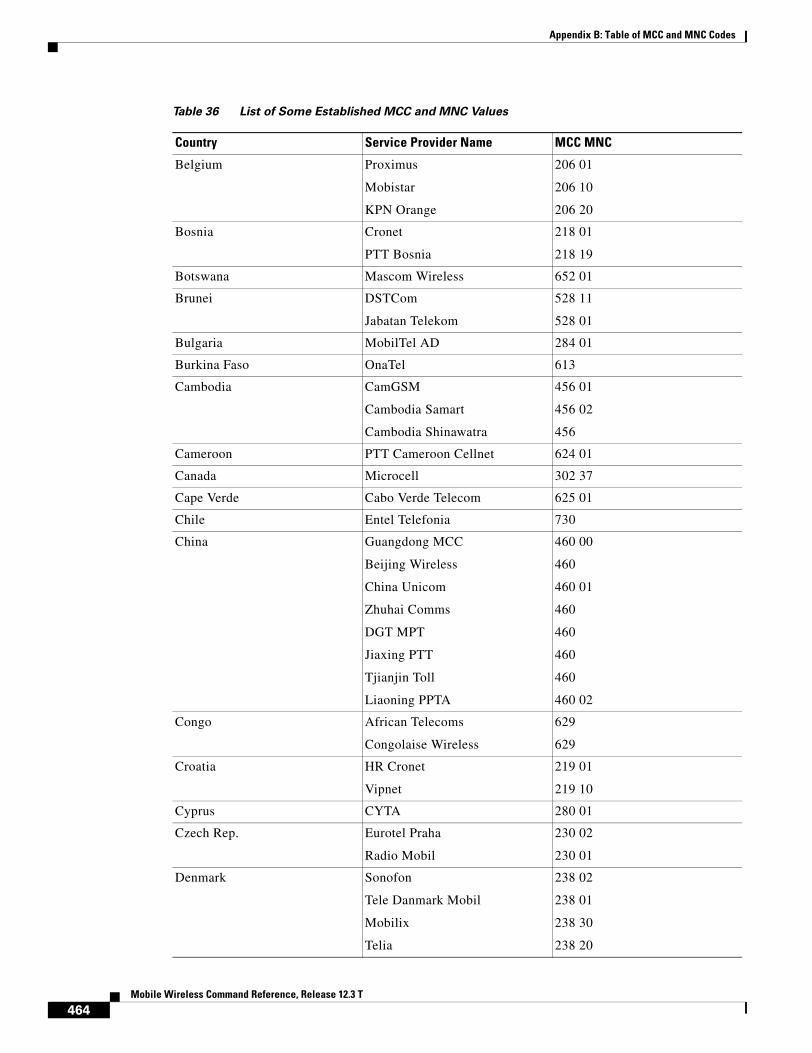
Appendix B: Table of MCC and MNC Codes
Belgium Proximus
Mobistar
KPN Orange
206 01
206 10
206 20
Bosnia Cronet
PTT Bosnia
218 01
218 19
Botswana Mascom Wireless 652 01
Brunei DSTCom
Jabatan Telekom
528 11
528 01
Bulgaria MobilTel AD 284 01
Burkina Faso OnaTel 613
Cambodia CamGSM
Cambodia Samart
Cambodia Shinawatra
456 01
456 02
456
Cameroon PTT Cameroon Cellnet 624 01
Canada Microcell 302 37
Cape Verde Cabo Verde Telecom 625 01
Chile Entel Telefonia 730
China Guangdong MCC
Beijing Wireless
China Unicom
Zhuhai Comms
DGT MPT
Jiaxing PTT
Tjianjin Toll
Liaoning PPTA
460 00
460
460 01
460
460
460
460
460 02
Congo African Telecoms
Congolaise Wireless
629
629
Croatia HR Cronet
Vipnet
219 01
219 10
Cyprus CYTA 280 01
Czech Rep. Eurotel Praha
Radio Mobil
230 02
230 01
Denmark Sonofon
Tele Danmark Mobil
Mobilix
Telia
238 02
238 01
238 30
238 20
Table 36 List of Some Established MCC and MNC Values
Country Service Provider Name MCC MNC
464Mobile Wireless Command Reference, Release 12.3 T

Appendix B: Table of MCC and MNC Codes
Egypt MobiNil
Click GSM
602 01
602 02
Estonia EMT
Radiolinja Eesti
Q GSM
248 01
248 02
248 03
Ethiopia ETA 636 01
Faroe Islands Faroese Telecom 288
Fiji Vodafone 542 01
Finland Radiolinja
Sonera
Alands Mobiltelefon
Telia
Finnet
Lnnen Puhelin
Helsingin Puhelin
244 05
244 91
244 05
244 03
244 09
244 09
244 09
France France Telecom
SFR
Bouygues Telekom
208 01
208 10
208 20
Fr.Polynesia Tikiphone 547 20
Fr.W.Indies Ameris 340 01
Georgia Superphone
Geocell
Magticom
282
282 01
282 02
Germany D1, DeTeMobil
D2, Mannesmann
E-Plus Mobilfunk
Viag Interkom
262 01
262 02
262 03
262 07
Ghana Franci Walker Ltd
ScanCom
620
620 01
Gibraltar GibTel 266 01
Table 36 List of Some Established MCC and MNC Values
Country Service Provider Name MCC MNC
465Mobile Wireless Command Reference, Release 12.3 T

Appendix B: Table of MCC and MNC Codes
Great Britain Cellnet
Vodafone
Jersey Telecom
Guernsey Telecom
Manx Telecom
One2One
Orange
234 10
234 15
234 50
234 55
234 58
234 30
234 33
Greece Panafon
STET
Cosmote
202 05
202 10
202 01
Greenland Tele Greenland 290
Guinea Int'l Wireless
Spacetel
Sotelgui
611
611
611 02
Hong Kong HK Hutchison
SmarTone
Telecom CSL
P Plus Comm
New World PCS
Mandarin Comm
Pacific Link
Peoples Telephone
SMC PCS
454 04
454 06
454 00
454 22
454 10
454 16
454 18
454 12
454 22
Hungary Pannon GSM
Westel 900
216 01
216 30
Table 36 List of Some Established MCC and MNC Values
Country Service Provider Name MCC MNC
466Mobile Wireless Command Reference, Release 12.3 T

Appendix B: Table of MCC and MNC Codes
India Airtel
Essar
Maxtouch
BPLMobile
Command
Mobilenet
Skycell
RPG MAA
Modi Telstra
Sterling Cellular
Mobile Telecom
Airtouch
BPL USWest
Koshika
Bharti Telenet
Birla Comm
Cellular Comms
TATA
Escotel
JT Mobiles
Evergrowth Telecom
Aircel Digilink
Hexacom India
Reliance Telecom
Fascel Limited
404 10
404 11
404 20
404 21
404 30
404 31
404 40
404 41
404 14
404 11
404
404
404
404
404
404
404 27
404 07
404 12
404
404
404 15
404
404
404
Indonesia TELKOMSEL
PT Satelit Palapa
Excelcom
PT Indosat
510 10
510 01
510 11
510
Iraq Iraq Telecom 418
Iran T.C.I.
Celcom
Kish Free Zone
432 11
432
432
Table 36 List of Some Established MCC and MNC Values
Country Service Provider Name MCC MNC
467Mobile Wireless Command Reference, Release 12.3 T

Appendix B: Table of MCC and MNC Codes
Ireland Eircell
Digifone
Meteor
272 01
272 02
272 03
Israel Partner Communications 425 01
Italy Omnitel
Telecom Italia Mobile
Wind
222 10
222 01
222 88
Ivory Coast Ivoiris
Telecel
Comstar
Loteny Telecom
612 03
612
612 01
612 05
Japan 440
Jordan MTS 416 01
Kenya Kenya Telecom 639
Kuwait MTCNet 419 02
Kyrgyz Rep Bitel Ltd 437 01
La Reunion SRR 647 10
Laos Lao Shinawatra 457 01
Latvia LMT
BALTCOM GSM
247 01
247 02
Lebanon Libancell
Cellis
415 03
415 01
Lesotho Vodacom 651 01
Liechtenstein Natel-D 228 01
Lithuania Omnitel
Bite GSM
246 01
246 02
Luxembourg P&T LUXGSM
Millicom Lux' S.A
270 01
270 77
Macao CTM 455 01
Macedonia PTT Makedonija 294 01
Madagascar Sacel
Madacom
SMM
646 03
646 01
646 02
Malawi TNL 650 01
Table 36 List of Some Established MCC and MNC Values
Country Service Provider Name MCC MNC
468Mobile Wireless Command Reference, Release 12.3 T

Appendix B: Table of MCC and MNC Codes
Malaysia Celcom
Maxis
My BSB
TM Touch
Adam
Digi Telecom
502 19
502 12
502 02
502 13
502 17
502 16
Malta Advanced
Telecell
278
278 01
Marocco O.N.P.T 604 01
Mauritius Cellplus 617 01
Monaco France Telecom
SFR
Office des Telephones
208 01
208 10
208
Montenegro Pro Monte 220 02
Mozambique Telecom de Mocambique
T.D.M GSM1800
634 01
634
Namibia MTC 649 01
Netherlands PTT Netherlands
Libertel
Telfort Holding NV
Ben
Dutchtone
204 08
204 04
204 12
204 16
204 20
New Caledonia Mobilis 546 01
New Zealand Bell South 530 01
Nigeria EMIS 621
Norway NetCom
TeleNor Mobil
242 02
242 01
Oman General Telecoms 422 02
Pakistan Mobilink 410 01
Papua Pacific 310 01
Philippines Globe Telecom
Islacom
Smart
515 02
515 01
515 03
Poland Plus GSM
ERA GSM
IDEA Centertel
260 01
260 02
260 03
Table 36 List of Some Established MCC and MNC Values
Country Service Provider Name MCC MNC
469Mobile Wireless Command Reference, Release 12.3 T

Appendix B: Table of MCC and MNC Codes
Portugal Telecel
TMN
Main Road Telecoms
Optimus
268 01
268 06
268
268 03
Qatar Q-Net 427 01
Romania MobiFon
MobilRom
226 01
226 10
Russia Mobile Tele... Moscow
United Telecom Moscow
NW GSM, St. Petersburg
Dontelekom
KB Impuls
JSC Siberian Cellular
BM Telecom
Beeline
Extel
Far Eastern Cell
250 01
250
250 02
250 10
250 99
250
250 07
250
250 28
250 12
San Marino Omnitel
Telecom Italia Mobile
Wind
222 10
222 01
222 88
Saudi Arabia Al Jawal
EAE
420 01
420 07
Senegal Sonatel 608 01
Seychelles SEZ SEYCEL
Airtel
633 01
633 10
Serbia Serbian PTT 220 03
Singapore Singapore Telecom
MobileOne
Binariang
525 01
525 03
525
Slovak Rep Eurotel
Globtel
231 02
231 01
Slovenia Mobitel
Si.Mobil
293 41
293 40
South Africa MTN
Vodacom
655 10
655 01
Table 36 List of Some Established MCC and MNC Values
Country Service Provider Name MCC MNC
470Mobile Wireless Command Reference, Release 12.3 T

Appendix B: Table of MCC and MNC Codes
Sri Lanka MTN Networks Pvt Ltd 413 02
Spain Airtel
Telefonica Spain
Amena
214 01
214 07
214 03
Sudan Mobitel 634 01
Swaziland 653
Sweden Comviq
Europolitan
Telia Mobile
240 07
240 08
240 01
Switzerland Swisscom 900
Swisscom 1800
diAx mobile
Orange
228 01
228 01
228 02
228
Syria SYR MOBILE 417 09
Taiwan LDTA
Mobitai
TransAsia
TWN
Tuntex
KGTelecom
FarEasTone
Chunghwa
466 92
466 93
466 99
466 97
466 06
466 88
466 01
466 11
Tanzania Tritel 640 01
Thailand TH AIS GSM
Total Access Comms
WCS
Hello
520 01
520 18
520 10
520 23
Tunisia Tunisian PTT 605 02
Turkey Telsim
Turkcell
286 02
286 01
UAE UAE ETISALAT-G1
UAE ETISALAT-G2
424 01
424 02
Uganda Celtel Cellular
MTN
641 01
641 10
Table 36 List of Some Established MCC and MNC Values
Country Service Provider Name MCC MNC
471Mobile Wireless Command Reference, Release 12.3 T
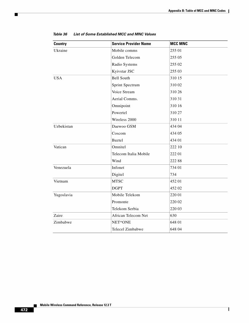
Appendix B: Table of MCC and MNC Codes
Ukraine Mobile comms
Golden Telecom
Radio Systems
Kyivstar JSC
255 01
255 05
255 02
255 03
USA Bell South
Sprint Spectrum
Voice Stream
Aerial Comms.
Omnipoint
Powertel
Wireless 2000
310 15
310 02
310 26
310 31
310 16
310 27
310 11
Uzbekistan Daewoo GSM
Coscom
Buztel
434 04
434 05
434 01
Vatican Omnitel
Telecom Italia Mobile
Wind
222 10
222 01
222 88
Venezuela Infonet
Digitel
734 01
734
Vietnam MTSC
DGPT
452 01
452 02
Yugoslavia Mobile Telekom
Promonte
Telekom Serbia
220 01
220 02
220 03
Zaire African Telecom Net 630
Zimbabwe NET*ONE
Telecel Zimbabwe
648 01
648 04
Table 36 List of Some Established MCC and MNC Values
Country Service Provider Name MCC MNC
472Mobile Wireless Command Reference, Release 12.3 T

B1R Cisco IOS Bridging and IBM Networking Command Reference, Volume 1 of 2
B2R Cisco IOS Bridging and IBM Networking Command Reference, Volume 2 of 2
DB Cisco IOS Debug Command Reference
DR Cisco IOS Dial Technologies Command Reference
FR Cisco IOS Configuration Fundamentals Command Reference
IP1R Cisco IOS IP Command Reference, Volume 1 of 3:Addressing and Services
IP2R Cisco IOS IP Command Reference, Volume 2 of 3:Routing Protocols
IP3R Cisco IOS IP Command Reference, Volume 3 of 3:Multicast
IPv6R Cisco IPv6 Command Reference
IR Cisco IOS Interface Command Reference
MWR Cisco IOS Mobile Wireless Command Reference
P2R Cisco IOS AppleTalk and Novell IPX Command Reference
P3R Cisco IOS Apollo Domain, Banyan VINES, DECnet, ISO CLNS, and XNS Command Reference
QR Cisco IOS Quality of Service Solutions Command Reference
SR Cisco IOS Security Command Reference
TR Cisco IOS Terminal Services Command Reference
VR Cisco IOS Voice, Video, and Fax Command Reference
WR Cisco IOS Wide-Area Networking Command Reference
XR Cisco IOS Switching Services Command Reference
Mobile Wireless C
Numerics
08a gprs charging message transfer-request command-ie MWR-137
08a show gprs umts-qos map traffic-class MWR-410
A
AAA (authentication, authorization, and accounting)
GGSN
accounting, enabling and disabling ?? to MWR-9
RADIUS, configuring with MWR-165
RADIUS server groups, configuring MWR-12 to MWR-13, MWR-152 to MWR-153
aaa accounting command MWR-9, MWR-13, MWR-153
aaa-accounting command MWR-8, MWR-13, MWR-153
aaa authentication command MWR-8, MWR-13, MWR-153
aaa authorization command MWR-8, MWR-13
aaa-group command MWR-9, MWR-12
aaa group server command MWR-8, MWR-13, MWR-153
aaa new-model command MWR-8, MWR-13
access control
GGSN
access groups, configuring MWR-263
authenticating users on MWR-16
violations, configuring response to MWR-24
See GGSN access groups
access groups
See GGSN access groups
access-mode command MWR-16, MWR-153
access-point command MWR-18
access-point configuration mode MWR-18
access point lists
See GGSN access point lists
access-point-name command MWR-20
access points
See GGSN access points
access-type command MWR-22
access-violation command MWR-24
ACCM (Asynchronous Control Character Map)
specifying MWR-281
aggregate command MWR-26
aggregate routes
on GGSN
configuring MWR-156
displaying MWR-28
473ommand Reference, Release 12.3 T

Index
anonymous access, enabling MWR-30
anonymous user command MWR-30
authentication
GGSN, configuring on MWR-16
B
block count command MWR-31
C
canonical QoS
GGSN
best-effort bandwidth factor, configuring MWR-110
enabling MWR-223
throughput, configuring MWR-116
ToS, mapping MWR-114
cautions
charging gateway
GGSN, disabling on MWR-133
ppp authentication command
using list-names (caution) MWR-284
cdma pdsn a10 ahdlc engine command MWR-34
cdma pdsn a10 gre sequencing command MWR-35
cdma pdsn a10 init-ppp-after-airlink-start airlink-start-timeout command MWR-36
cdma pdsn a10 max-lifetime command MWR-38
cdma pdsn a11 mandate presence airlink-setup command MWR-40
cdma pdsn accounting local-timezone command MWR-41
cdma pdsn accounting send cdma-ip-tech command MWR-43
cdma pdsn accounting send command MWR-42
cdma pdsn accounting time-of-day command MWR-44
cdma pdsn age-idle-users command MWR-45
cdma pdsn all dormant ppp-idle-timeout send-termreq command MWR-39
cdma pdsn cluster controller command MWR-46
cdma pdsn cluster controller session-high command MWR-47
474Mobile Wireless Command Reference, Release 12.3 T
cdma pdsn cluster controller session-low command MWR-48
cdma pdsn cluster member command MWR-49
cdma pdsn compliance iosv4.1 session-reference command MWR-50
cdma pdsn compliance is835 esn-optional command MWR-51
cdma pdsn failure-history command MWR-52
cdma pdsn ingress-address-filtering command MWR-53
cdma pdsn maximum pcf command MWR-54
cdma pdsn maximum sessions command MWR-55
cdma pdsn mobile-advertisement-burst command MWR-56
cdma pdsn msid-authentication command MWR-57
cdma pdsn retransmit a11-update command MWR-59
cdma pdsn secure cluster command MWR-60
cdma pdsn secure pcf command MWR-61
cdma pdsn selection interface command MWR-63
cdma pdsn selection keepalive command MWR-65
cdma pdsn selection load-balancing command MWR-66
cdma pdsn selection session-table-size command MWR-67
cdma pdsn send-agent-adv command MWR-68
cdma pdsn timeout a11-update command MWR-69
cdma pdsn timeout mobile-ip-registration command MWR-70
cdma pdsn virtual-template command MWR-71
CDR (call detail record)
GGSN
aggregation limit, configuring MWR-119
apn selection mode, enabling MWR-122
charging container maximum, configuring MWR-126
charging container volume, configuring MWR-130
clearing on MWR-78, MWR-132
for roamers, enabling MWR-145
local record sequence number, enabling MWR-123

Index
maximum number, configuring MWR-119
MSISDN, enabling MWR-124
node ID, enabling MWR-123
packet counts, enabling MWR-124
trigger conditions MWR-126
CEF (Cisco Express Forwarding)
on GGSN
GPRS load balancing, configuring MWR-228
requirement for VRF MWR-440
UDP checksum, disabling MWR-183
charging function
on GGSN, disabling MWR-79
charging gateway
See GGSN charging gateway
clear cdma pdsn cluster controller session records age command MWR-72
clear cdma pdsn selection command MWR-73
clear cdma pdsn session command MWR-74
clear cdma pdsn statistics command MWR-75
clear gprs access-point statistics command MWR-77
clear gprs charging cdr command MWR-78
clear gprs gtp-director statistics command MWR-83, MWR-400
clear gprs gtp pdp-context command MWR-80
clear gprs gtp statistics command MWR-82
clear gprs isgsn statistics command MWR450
clear ip mobile host-counters command MWR-84
clear ip mobile secure command MWR-86
clear ip mobile visitor command MWR-88
clear ip rtp header-compression MWR-91
clear ip rtp header-compression command MWR-90
clear l2relay statistics command MWR451
clear l2relay topology-map command MWR452
clear ppp mux command MWR-91
clear radius local-server command MWR-92
control sequences
escape characters for ACCM, specifying PPP MWR-281
counters, PPP multiplexing MWR-415
crypto map (global IPSec) command MWR-94
D
delay QoS
GGSN
enabling MWR-224
ToS, mapping MWR-170
DHCP (Dynamic Host Configuration Protocol)
GGSN access points
gateway address, configuring MWR-99
proxy client, configuring MWR-101
server, configuring MWR-101, MWR-163
GPRS default server, configuring MWR-162, MWR-165
dhcp-gateway-address command MWR-99
dhcp-server command MWR-101
dns primary command MWR-105, MWR-275
E
echo timer
on GGSN
dynamic echo timer, enabling MWR-175
dynamic minimum, configuring MWR-178
dynamic smooth factor, configuring MWR-180
path echo interval, configuring MWR-189
encapsulation gtp command MWR-107
F
flow control
GGSN
GTP, configuring for MWR-182
frame
sub, count MWR-291
super, size MWR-289
475Mobile Wireless Command Reference, Release 12.3 T

Index
G
GDM (GTP Director Module)
retry timer, configuring MWR-200
service type, configuring MWR-313
GGSN access groups, configuring MWR-263
GGSN access point lists, configuring MWR-108
GGSN access points
access type, configuring MWR-22
accounting, enabling and disabling ?? to MWR-9
authenticating users MWR-16
CDRs, clearing MWR-78
configuring MWR-18
DHCP gateway, configuring MWR-99
DHCP server, configuring MWR-101, MWR-163
displaying MWR-350
GTP-PPP regeneration, enabling MWR-294
idle sessions
configuring MWR-314
IP access lists, specifying MWR-263
IP address pools, configuring MWR-265
naming MWR-20
network-initiated PDP context support
enabling MWR-279
PDP contexts, clearing MWR-80
RADIUS server groups, configuring MWR-12 to MWR-13, MWR-152 to MWR-153
statistics, clearing MWR-77
statistics, displaying MWR-356
subscriptions, configuring MWR-435
VRF, configuring MWR-440
See also GGSN access point lists
GGSN charging gateway
alternate gateway
switch-over timer, configuring MWR-148
476Mobile Wireless Command Reference, Release 12.3 T
backup gateway, configuring MWR-160
buffer size, configuring MWR-147
CDRs
apn selection mode, enabling MWR-122
container maximum, configuring MWR-126
container volume, configuring MWR-130
for roamers, enabling MWR-145
local record sequence number, enabling MWR-123
maximum number, specifying MWR-119
MSISDN, enabling MWR-124
node ID, enabling MWR-123
packet counts, enabling MWR-124
tariff time changes MWR-150
trigger conditions MWR-126
charging data
mapping IP ToS to MWR-135, MWR-136
transfer frequency, configuring MWR-138, MWR-151
transfer request queue size, specifying MWR-139
charging processing
(caution) MWR-133
disabling MWR-132
default gateway, configuring MWR-160
flow control echo signal, enabling MWR-134
parameter configuration, displaying MWR-360
path protocol, configuring MWR-141
port, configuring MWR-142
statistics, displaying cumulative MWR-365
statistics, displaying current MWR-367
tariff times, configuring MWR-150
TCP path, establishing MWR-125
GPRS (General Packet Radio Service)
GSN type, configuring MWR-312
throughput, configuring MWR-112
GDM service type, configuring MWR-313
gprs access-point-list command MWR-108
gprs canonical-qos best-effort bandwidth-factor command MWR-110
gprs canonical-qos gsn-resource-factor command MWR-112
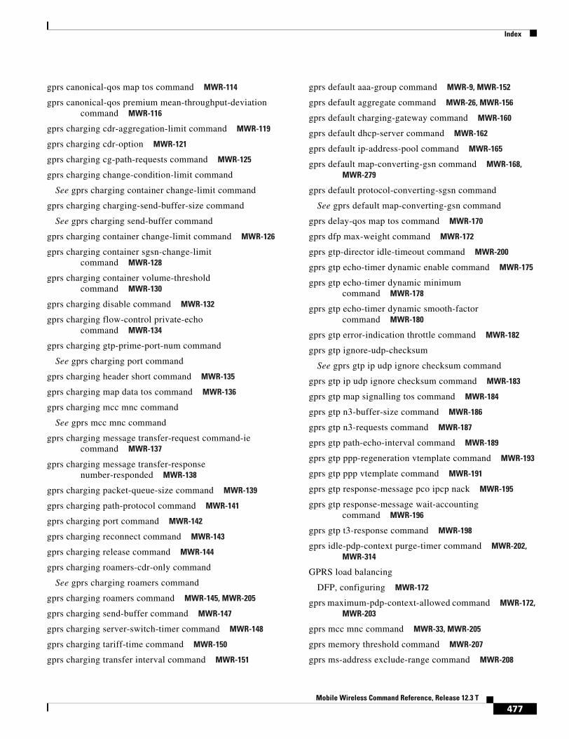
Index
gprs canonical-qos map tos command MWR-114
gprs canonical-qos premium mean-throughput-deviation command MWR-116
gprs charging cdr-aggregation-limit command MWR-119
gprs charging cdr-option MWR-121
gprs charging cg-path-requests command MWR-125
gprs charging change-condition-limit command
See gprs charging container change-limit command
gprs charging charging-send-buffer-size command
See gprs charging send-buffer command
gprs charging container change-limit command MWR-126
gprs charging container sgsn-change-limit command MWR-128
gprs charging container volume-threshold command MWR-130
gprs charging disable command MWR-132
gprs charging flow-control private-echo command MWR-134
gprs charging gtp-prime-port-num command
See gprs charging port command
gprs charging header short command MWR-135
gprs charging map data tos command MWR-136
gprs charging mcc mnc command
See gprs mcc mnc command
gprs charging message transfer-request command-ie command MWR-137
gprs charging message transfer-response number-responded MWR-138
gprs charging packet-queue-size command MWR-139
gprs charging path-protocol command MWR-141
gprs charging port command MWR-142
gprs charging reconnect command MWR-143
gprs charging release command MWR-144
gprs charging roamers-cdr-only command
See gprs charging roamers command
gprs charging roamers command MWR-145, MWR-205
gprs charging send-buffer command MWR-147
gprs charging server-switch-timer command MWR-148
gprs charging tariff-time command MWR-150
gprs charging transfer interval command MWR-151
gprs default aaa-group command MWR-9, MWR-152
gprs default aggregate command MWR-26, MWR-156
gprs default charging-gateway command MWR-160
gprs default dhcp-server command MWR-162
gprs default ip-address-pool command MWR-165
gprs default map-converting-gsn command MWR-168, MWR-279
gprs default protocol-converting-sgsn command
See gprs default map-converting-gsn command
gprs delay-qos map tos command MWR-170
gprs dfp max-weight command MWR-172
gprs gtp-director idle-timeout command MWR-200
gprs gtp echo-timer dynamic enable command MWR-175
gprs gtp echo-timer dynamic minimum command MWR-178
gprs gtp echo-timer dynamic smooth-factor command MWR-180
gprs gtp error-indication throttle command MWR-182
gprs gtp ignore-udp-checksum
See gprs gtp ip udp ignore checksum command
gprs gtp ip udp ignore checksum command MWR-183
gprs gtp map signalling tos command MWR-184
gprs gtp n3-buffer-size command MWR-186
gprs gtp n3-requests command MWR-187
gprs gtp path-echo-interval command MWR-189
gprs gtp ppp-regeneration vtemplate command MWR-193
gprs gtp ppp vtemplate command MWR-191
gprs gtp response-message pco ipcp nack MWR-195
gprs gtp response-message wait-accounting command MWR-196
gprs gtp t3-response command MWR-198
gprs idle-pdp-context purge-timer command MWR-202, MWR-314
GPRS load balancing
DFP, configuring MWR-172
gprs maximum-pdp-context-allowed command MWR-172, MWR-203
gprs mcc mnc command MWR-33, MWR-205
gprs memory threshold command MWR-207
gprs ms-address exclude-range command MWR-208
477Mobile Wireless Command Reference, Release 12.3 T

Index
gprs ni-pdp cache-timeout command MWR-210
gprs ni-pdp discard-period command MWR-212
gprs ni-pdp ip-imsi single command MWR-214, MWR-279
gprs ni-pdp pdp-buffer command MWR-216
gprs ni-pdp percentage command MWR-218
gprs ntwk-init-pdp ip-imsi single command
See gprs ni-pdp ip-imsi single command
gprs ntwk-init-pdp max-buffer-per-pdp command
See gprs ni-pdp pdp-buffer command
gprs ntwk-init-pdp max-ntwk-init-pdp-percentage command
See gprs ni-pdp percentage command
gprs ntwk-init-pdp pdu-discard-period command
See gprs ni-pdp discard-period command
gprs ntwk-init-pdp sgsn-cache-timeout command
See gprs ni-pdp cache-timeout command
gprs plmn ip address MWR-220
gprs qos default-response requested command MWR-222
gprs qos map canonical-qos command MWR-223
gprs qos map delay command MWR-224
gprs qos map umts command MWR-225
gprs radius attribute chap-challenge command MWR-226
gprs radius msisdn first-byte command MWR-227
gprs slb cef command MWR-228
gprs umts-qos dscp unmodified command MWR-230
gprs umts-qos map diffserv-phb command MWR-232
gprs umts-qos map traffic-class command MWR-234
group (local RADIUS server) command MWR-239
GTP (GPRS Tunneling Protocol)
echo-request messages
interval on GGSN, configuring MWR-189
encapsulation on GGSN, configuring MWR-105, MWR-107, MWR-275
error messages
maximum number on GGSN, configuring MWR-182
GGSN parameters, displaying MWR-372
GGSN paths, configuring MWR-375
N3 buffer on GGSN, configuring size of MWR-186
path failures
478Mobile Wireless Command Reference, Release 12.3 T
echo-request message interval, configuring MWR-189
signaling packets on GGSN
IP ToS, mapping MWR-184
N3 buffer, configuring MWR-186
signaling requests
GGSN response time, configuring MWR-198
retry attempts on GGSN, configuring MWR-187
statistics on GDM
clearing MWR-83, MWR-400
displaying MWR-400
statistics on GGSN
clearing MWR-82, MWR-389
displaying MWR-389
status on GGSN, displaying MWR-394
GTP-PPP regeneration
on GGSN
enabling MWR-294
H
header compression
clearing MWR-91
I
IMSI (International Mobile Subscriber Identity)
PDP contexts, clearing MWR-80
interface cdma-Ix1 command MWR-241
ip-access-group command MWR-263
IP addresses
GGSN
DHCP, configuring MWR-165
pools, configuring MWR-101, MWR-265
RADIUS, configuring MWR-165
route aggregation, configuring MWR-26
ip-address-pool command MWR-265
ip mobile foreign-agent skip-aaa-reauthentication command MWR-242
ip mobile prefix-length command MWR-252

Index
ip mobile registration-lifetime command MWR-253
ip mobile secure command MWR-254
ip mobile secure host command MWR-254
ip probe path command MWR-257
ip rtp compression-connections command MWR-258
ip rtp header-compression command MWR-260
K
keepalive command MWR-268
L
l2relay echo-interval command MWR453
l2relay flow-control command MWR454
l2relay pilot-uid command MWR455
l2relay use-interface command MWR456
M
MCC (mobile country code)
on GGSN
configuring MWR-205
reference table MWR-463
MNC (mobile network code)
on GGSN
configuring MWR-205
reference table MWR-463
mobile sessions
GGSN
access point subscriptions, configuring MWR-435
clearing on MWR-80
IP addressing, specifying method for MWR-165
purge timer, configuring MWR-202
purge timer, configuring at access points MWR-314
users, authenticating MWR-16
mobile stations
IP addresses
allocating MWR-101
excluded range, configuring MWR-208
excluded range, displaying MWR-402, MWR-404
mode y-cable MWR-270
MSISDN (Mobile Station International PSTN/ISDN)
RADIUS request, including in MWR-226, MWR-227
MSISDN (Mobile Station international PSTN/ISDN)
RADIUS requests
overriding in MWR-271
msisdn suppression command MWR-271, MWR-296, MWR-297, MWR-299, MWR-300
multiplexing PPP
command MWR-286
delay MWR-287
displaying counters MWR-415
protocol ID MWR-290
subframe count MWR-291
subframe size MWR-293
superframe size MWR-289
N
nas command MWR-273
network-behind-mobile command MWR-277
network-initiated PDP contexts
buffer size, configuring MWR-216
cache for SGSN addresses, configuring MWR-210
discard period, configuring MWR-212
enabling MWR-279
MAP-converting GSN, configuring MWR-168
static IP to IMSI address mapping, configuring MWR-214
network-request-activation command MWR-279
479Mobile Wireless Command Reference, Release 12.3 T

Index
P
PDN (public data network)
GGSN access points
configuring MWR-18, MWR-20
naming MWR-20
PDP (packet data protocol) contexts
GDM
displaying requests on MWR-397
GGSN
clearing on MWR-80
displaying on MWR-379
idle sessions, purging MWR-202, MWR-314
maximum, configuring MWR-203
maximum with DFP, configuring MWR-172
See also network-initiated PDP contexts
PPP (point to point protocol)
on GGSN
GTP-PPP regeneration, enabling MWR-294
ppp accm command MWR-281
ppp authentication command MWR-283
using list-names (caution) MWR-284
PPP multiplexing
command MWR-286
delay MWR-287
dislpaying counters MWR-415
protocol ID MWR-290
subframe count MWR-291
subframe size MWR-293
superframe size MWR-289
ppp mux MWR-286
ppp mux delay MWR-287
ppp mux frame MWR-289
ppp mux pid MWR-290
ppp mux subframe count MWR-291
ppp-regeneration command MWR-294
protocol ID MWR-290
480Mobile Wireless Command Reference, Release 12.3 T
Q
QoS (quality of service)
GGSN
best-effort bandwidth factor, configuring MWR-110
canonical QoS, configuring MWR-116
canonical QoS, enabling MWR-223
delay QoS, enabling MWR-224
GGSN default response, configuring MWR-222
throughput, configuring MWR-112
ToS, mapping for canonical QoS MWR-114
ToS, mapping for delay QoS MWR-170
R
RADIUS (Remote Access Dial-In User Service)
AAA server groups
GGSN, configuring on MWR-165
accounting on GGSN
waiting for response message, enabling MWR-196
GGSN access points
configuring accounting ?? to MWR-9, MWR-236
configuring server groups MWR-12 to MWR-13, MWR-152 to MWR-153
including MSISDN IE MWR-226, MWR-227
overriding MSISDN MWR-271
radius-server host command MWR-9, MWR-13, MWR-153
radius-server local command MWR-301
reauthentication time command MWR-303
redirect all ip command MWR-305
redirect intermobile ip command MWR-306
redundancy
command MWR-307, MWR-432, MWR-433
response-message wait-accounting command MWR-236
roamers on GGSN
blocking access MWR-33
charging, enabling MWR-145
Index
route aggregation
on GGSN
configuring MWR-156
displaying MWR-28
RTP header compression
connections supported MWR-258
enabling MWR-260
statistics
clearing MWR-90
S
security verify command MWR-309
service cdma pdsn command MWR-311
service gprs ggsn command MWR-312
service gprs gtp-director command MWR-313
session idle-time command MWR-314
show cdma pdsn accounting detail command MWR-321
show cdma pdsn accounting session command MWR-324
show cdma pdsn accounting session detail command MWR-325
show cdma pdsn accounting session flow command MWR-327
show cdma pdsn accounting session flow user command MWR-328
show cdma pdsn ahdlc command MWR-329
show cdma pdsn cluster controller command MWR-330
show cdma pdsn cluster controller configuration command MWR-331
show cdma pdsn cluster controller member command MWR-332
show cdma pdsn cluster controller session command MWR-333
show cdma pdsn cluster controller statistics command MWR-334
show cdma pdsn cluster member command MWR-335
show cdma pdsn command MWR-317
show cdma pdsn flow command MWR-336
show cdma pdsn pcf command MWR-338
show cdma pdsn resource command MWR-340
show cdma pdsn selection command MWR-341
show cdma pdsn session command MWR-342
show cdma pdsn statistics command MWR-343
show csma pdsn accounting command MWR-319
show gprs access-point command MWR-345
show gprs access-point statistics command MWR-356
show gprs charging parameters command MWR-359
show gprs charging statistics command MWR-365
show gprs charging status command MWR-367
show gprs gtp-director pdp-context command MWR-397
show gprs gtp-director statistics command MWR-400
show gprs gtp ms command MWR-370
show gprs gtp parameters command MWR-372
show gprs gtp path command MWR-375
show gprs gtp pdp-context command MWR-377
show gprs gtp statistics command MWR-388
show gprs gtp status command MWR-393
show gprs isgsn statistics command MWR457
show gprs ms-address exclude-range command MWR-402, MWR-404
show gprs qos status command MWR-406
show gprs umts-qos map traffic-class command MWR-410
show ip route command MWR-28
show ip rtp header-compression command MWR-412
show l2relay statistics command MWR459
show ppp mux MWR-415
show radius local-server statistics command MWR-417
show slccp wds command MWR-427
show tech support cdma pdsn command MWR-419
snmp-server enable traps cdma command MWR-429
ssid command MWR-430
standalone MWR-432
standby use-interface MWR-307, MWR-433
static routes
GGSN
reducing on MWR-27
verifying on MWR-28
481Mobile Wireless Command Reference, Release 12.3 T

Index
subframe count MWR-291
subframe size
frame
sub, size MWR-293
subscription-required command MWR-435
superframe size MWR-289
T
TID (tunnel ID)
CDRs, clearing MWR-78
ToS (type of service)
GGSN
canonical QoS, mapping MWR-114
charging data, mapping to MWR-135, MWR-136
delay QoS, mapping MWR-170
GTP signaling packets, mapping to MWR-184
U
UPD checksum
on GGSN
disabling MWR-183
user command MWR-436
V
virtual template interfaces
GGSN
GTP encapsulation, configuring MWR-105, MWR-107, MWR-275
PPP, configuring MWR-191
PPP regeneration, configuring MWR-193
vlan command MWR-438
VRF (virtual routing and forwarding)
on GGSN
configuring MWR-440
DHCP server, configuring MWR-102
vrf command MWR-440
482Mobile Wireless Command Reference, Release 12.3 T
W
wlccp authentication-server client command MWR-443
wlccp authentication-server infrastructure command MWR-445
wlccp wds priority interface command MWR-446
Y
y cable command MWR-270