Embed Size (px)
Citation preview

Cisco 4G LTE and Cisco 4G LTE-Advanced Network Interface Module Installation Guide
First Published: 2016-12-09
Last Updated: 2017-4-5
This document provides an overview of the hardware and installation information for the Cisco 4G LTE and Cisco 4G LTE-Advanced Network Interface Module (NIM) Installation Guide on the Cisco 4000 Series Integrated Services Router (ISR).
This document contains the following sections:
Hardware Overview, page 1
Ports and LEDs, page 4
Supported Antennas and Cables, page 8
Recommended Practices for the Cisco 4G LTE NIM and the Cisco 4G LTE-Advanced NIM, page 10
— Safety Recommendations, page 10
— Preventing Electrostatic Discharge Damage, page 11
— General Maintenance Guidelines, page 11
— Safety Warnings, page 11
Installing the SIM card on the Cisco 4G LTE NIM, page 13
Installing the SIM card on the Cisco 4G LTE-Advanced NIM, page 15
Installing the NIM into a Cisco 4000 Series ISR, page 17
Removing the NIM from a Cisco 4000 Series ISR, page 18
Related Documents, page 18
Hardware OverviewCisco 4G LTE NIM and Cisco 4G LTE-Advanced NIM expands existing 4G LTE coverage with new Frequency Division Duplexing (FDD) and Time Division Duplexing (TDD) frequency bands.
Table 1 describes the SKUs for the Cisco 4G LTE NIM and the Cisco 4G LTE-Advanced NIM.
1
Cisco Systems, Inc. www.cisco.com

Cisco 4G LTE and Cisco 4G LTE-Advanced Network Interface Module Installation Guide
Table 1 Cisco 4G LTE NIM and Cisco 4G LTE-Advanced NIM SKUs
Cisco 4G LTE NIM and Cisco 4G LTE-Advanced NIM SKUs
Description Mode Operating Region
Band
NIM-4G-LTE-LA Cisco 4G LTE NIM module (LTE 2.5) for LATAM/APAC carriers.
This SKU is based on Sierra Wireless MC7430 modem.
LTE: FDD
LTE: TDD
DC-HSPA+, HSPA+, HSPA, UMTS
TD-SCDMA
Latin America, Asia-Pacific
LTE bands 1, 3, 5, 7, 8, 18, 19, 21, 28, 38, 39, 40, and 41
FDD LTE 700 MHz (band 28), 850 MHz (band 5 CLR), 850 MHz (bands 18 and 19 Low), 900 MHz (band 8), 1500 MHz (band 21), 1800 MHz (band 3), 2100 MHz (band 1), or 2600 MHz (band 7)
TDD LTE 1900 MHz (band 39), 2300 MHz (band 40), 2500 MHz (band 41), or 2600 MHz (band 38)
NIM-LTEA-LA Cisco 4G LTE-Advanced NIM module (LTE3.0) for LATAM/APAC carriers.
This SKU is based on Sierra Wireless EM7430 modem.
LTE: FDD
LTE: TDD
DC-HSPA+,HSPA+, HSPA,UMTS
Latin America, Asia-Pacific
LTE bands 1, 3, 5, 7, 8, 18, 19, 21, 28, 38, 39, 40, and 41
FDD LTE 700 MHz (band 28), 850 MHz (band 5 CLR), 850 MHz (bands 18 and 19 Low), 900 MHz (band 8), 1500 MHz (band 21), 1800 MHz (band 3), 2100 MHz (band 1), or 2600 MHz (band 7)
TDD LTE 1900 MHz (band 39), 2300 MHz (band 40), 2500 MHz (band 41), or 2600 MHz (band 38)
Carrier aggregation band combinations:
1+(8,18,19,21); 3+(5,7,19,28); 7+(5,7,28); 19+21, 38+38, 39+39,40+40, and 41+41
2
Cisco 4G LTE and Cisco 4G LTE-Advanced Network Interface Module Installation Guide
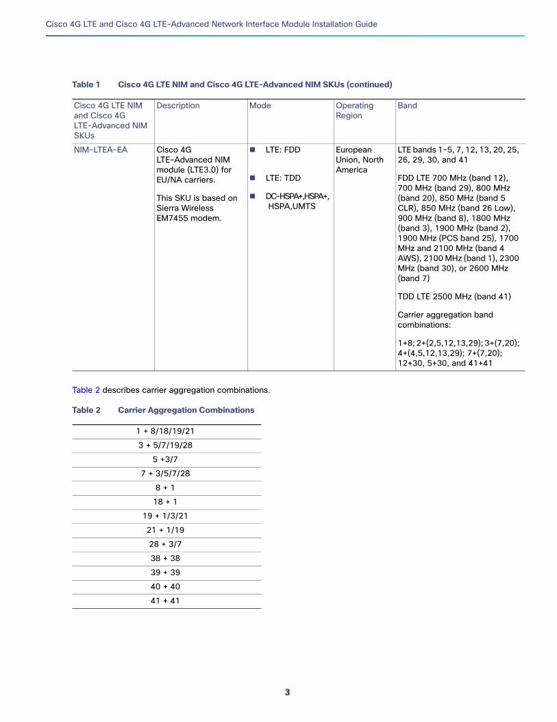
Table 2 describes carrier aggregation combinations.
NIM-LTEA-EA Cisco 4G LTE-Advanced NIM module (LTE3.0) for EU/NA carriers.
This SKU is based on Sierra Wireless EM7455 modem.
LTE: FDD
LTE: TDD
DC-HSPA+,HSPA+, HSPA,UMTS
European Union, North America
LTE bands 1-5, 7, 12, 13, 20, 25, 26, 29, 30, and 41
FDD LTE 700 MHz (band 12), 700 MHz (band 29), 800 MHz (band 20), 850 MHz (band 5 CLR), 850 MHz (band 26 Low), 900 MHz (band 8), 1800 MHz (band 3), 1900 MHz (band 2), 1900 MHz (PCS band 25), 1700 MHz and 2100 MHz (band 4 AWS), 2100 MHz (band 1), 2300 MHz (band 30), or 2600 MHz (band 7)
TDD LTE 2500 MHz (band 41)
Carrier aggregation band combinations:
1+8; 2+(2,5,12,13,29); 3+(7,20); 4+(4,5,12,13,29); 7+(7,20); 12+30, 5+30, and 41+41
Table 2 Carrier Aggregation Combinations
1 + 8/18/19/21
3 + 5/7/19/28
5 +3/7
7 + 3/5/7/28
8 + 1
18 + 1
19 + 1/3/21
21 + 1/19
28 + 3/7
38 + 38
39 + 39
40 + 40
41 + 41
Table 1 Cisco 4G LTE NIM and Cisco 4G LTE-Advanced NIM SKUs (continued)
Cisco 4G LTE NIM and Cisco 4G LTE-Advanced NIM SKUs
Description Mode Operating Region
Band
3

Cisco 4G LTE and Cisco 4G LTE-Advanced Network Interface Module Installation Guide
Ports and LEDsFigure 1 shows the Cisco 4G LTE NIM front panel.
Figure 1 Front Panel of the Cisco 4G LTE NIM
Table 3 lists the Cisco 4G LTE NIM ports and LED indicators and describes their behavior. The LEDs provide a visual indication of the NIM status and the currently selected services.
Note: You should remove the caps before attaching the antennas.
1 PID Name 2 LED—EN
3 LED—GPS (Global Positioning System) 4 LED—WWAN
5 RSVD (reserved) port, USB 2.0 mini type B 6 LED—SERVICE
7 LED—RSSI (Received Signal Strength Indicator) 8 M1 DIV—Diversity Antenna Connector Threaded Neill–Concelman (TNC), with dust cap removed.
9 GPS—Global Positioning System Antenna Connector (SubMiniature version A), with knurled metal cap removed.
10 M0 MAIN—Main Antenna Connector Threaded Neill–Concelman (TNC), with dust cap removed.
Table 3 Cisco 4G LTE NIM Ports and LED Indicators
Ports, Connectors, and LEDs Description
RSVD (Port) The reserved (RSVD) diagnostic port is not required for normal activation or operation. This port supports modem debug or provisioning.
EN (LED) The Enable (EN) LED is standard on NIMs and indicates the module state.
Solid green—Indicates powered on status and functioning normally.
Solid amber—Indicates module has some type of failure.
Off—Indicates module does not have power. It may also remain off the first time when the NIM is powered on, until it is configured by the host software.
EN
3659
78
GPS WWAN SERVICE RSSI
M0MAIN
M1DIV
GPS
RSVD
4G LTE-LA
NIM
2 3 4 65 7
1
910 8
4

Cisco 4G LTE and Cisco 4G LTE-Advanced Network Interface Module Installation Guide
WWAN (LED) Indicates the modem status.
Solid green—Indicates the modem is powered, associated, and authenticated but not receiving or transmitting data.
Slow blinking green—Indicates the modem is powered, but not associated or authenticated; still searching for service. Check the antenna, cable, SIM card, or the user account with your service provider.
Fast blinking green—Indicates the modem is powered and is transmitting or receiving. The blink rate is proportional to the transmitted and received data rate.
Solid Amber—Indicates the modem is reserved for future use.
Off—Indicates the modem is in reset mode.
RSSI (LED) Indicates the level of signal strength received by the NIM.
Solid green—Indicates a high RSSI (greater than –69 dBm).
Solid blue—Indicates medium RSSI (-89 to -69dBm).
Solid amber—Indicates low RSSI (-99 to -89dBm).
Amber blink—Indicates RSSI is below -100dBm.
Off—Indicates no service detected.
SERVICE (LED) Indicates which cellular service is available.
Solid green—Indicates 4G service is enabled (LTE).
Solid blue—Indicates 3G service is enabled, e.g. EDVO, HSPA+.
Solid amber—Indicates 2G service is enabled, e.g. 1xRTT, EDGE.
Off—Indicates no service detected.
GPS (LED) Indicates whether GPS service is enabled.
Solid green—Indicates GPS service is enabled.
Off—Indicates the GPS is not active or not detected.
M1 DIV (Port) Diversity Antenna Connector (TNC), with dust caps removed.
GPS (Port) GPS Antenna Connector (SMA), with knurled metal cap.
M0 MAIN (Port) Main Antenna Connector (TNC), with dust caps removed.
Table 3 Cisco 4G LTE NIM Ports and LED Indicators (continued)
Ports, Connectors, and LEDs Description
5

Cisco 4G LTE and Cisco 4G LTE-Advanced Network Interface Module Installation Guide
Figure 2 shows the Cisco 4G LTE-Advanced NIM front panel.
Figure 2 Front Panel of the Cisco 4G LTE-Advanced NIM
Table 4 lists the Cisco 4G LTE-Advanced NIM ports and LED indicators and describes their behavior. The LEDs provide a visual indication of the NIM status and the currently selected services.
Note: You should remove the caps before attaching the antennas.
1 PID Name 2 LED—EN
3 LED—SIM0 4 LED—SIM1
5 LED—RSSI 6 RSVD (reserved) port, USB 2.0 mini type B
7 LED—GPS 8 LED—SERVICE
9 M1 DIV—Diversity Antenna Connector (TNC), with dust cap removed.
10 GPS—GPS Antenna Connector (SMA), with knurled metal cap removed.
11 M0 MAIN—Main Antenna Connector (TNC), with dust cap removed.
Table 4 Cisco 4G LTE-Advanced NIM Ports and LED Indicators
Ports, Connectors, and LEDs Description
RSVD (Port) The reserved (RSVD) diagnostic port is not required for normal activation or operation. This port supports modem debug or provisioning.
EN (LED) The Enable (EN) LED is standard on NIMs and indicates the module state, as shown in Figure 2.
Solid green—Indicates powered on status and functioning normally.
Solid amber—Indicates module has some type of failure.
Off—Indicates module does not have power. It may also remain off the first time when the NIM is powered on, until it is configured by the host software.
NIM-LTEA-LA
3658
13
NIM
M0MAIN
M1DIV
GPS
EN GPS SERVICESIM0
RSSI
SIM1
RSVD
1
2 3 4 765 8
911 10
6

Cisco 4G LTE and Cisco 4G LTE-Advanced Network Interface Module Installation Guide
SIM0 and SIM1 (LED) Indicates the modem status.
Green when SIM card is active, amber when SIM card is standby, OFF when SIM card is absent. In addition to the green color, the blink pattern of the SIM0 and SIM1 LED indicates the modem status:
Solid green—Indicates the modem is powered, associated, and authenticated but not receiving or transmitting data.
Slow blinking green (On 5sec, Off 200ms)—Indicates the modem is powered, but not associated or authenticated; still searching for service. Check the antenna, cable, SIM card, or the user account with your service provider.
Fast blinking green (On 400ms, Off 100ms)—Indicates the modem is powered and is transmitting or receiving.
Green blinking (On 500ms, Off 500ms)—Indicates the modem is in low power mode. Modem radio is Off.
Green very slow blinking (On 500ms, Off 500ms, On 500ms, off 500ms, off 30ms)—Indicates the modem is receiving power, associated, and authenticated on a roaming network.
Off—Indicates the modem is in reset mode.
RSSI (LED) Indicates the received signal strength driven by the software.
One solid green LED—Indicates RSSI is under –100dBm.
Two solid green LEDs—Indicates low RSSI (-99 to -89dBm).
Three solid green LEDs—Indicates medium RSSI (-89 to -69dBm).
Four solid green LEDs —Indicates high RSSI (greater than -69dBm).
Off—Indicates no service detected.
SERVICE (LED) Indicates which cellular service is available.
Solid green—Indicates 4G service is enabled (LTE).
Solid blue—Indicates 3G service is enabled, e.g. EDVO, HSPA+.
Solid amber—Indicates 2G service is enabled, e.g. 1xRTT, EDGE.
Off—Indicates no service detected.
GPS (LED) Indicates whether GPS service is enabled.
Solid green—Indicates GPS service is enabled.
Off—Indicates the GPS is not active or not detected.
M1 DIV (Port) Diversity Antenna Connector (TNC), with dust caps removed.
GPS (Port) GPS Antenna Connector (SMA), with knurled metal cap.
M0 MAIN (Port) Main Antenna Connector (TNC), with dust caps removed.
Table 4 Cisco 4G LTE-Advanced NIM Ports and LED Indicators (continued)
Ports, Connectors, and LEDs Description
7

Cisco 4G LTE and Cisco 4G LTE-Advanced Network Interface Module Installation Guide
Supported Antennas and CablesTable 5 lists the Cisco antennas that are supported for use on the Cisco 4G LTE NIM and Cisco 4G LTE-Advanced NIM:
Table 5 Supported Antennas
Cisco Part Number Description Maximum Gain and Frequency Ranges
Notes
4G-LTE-ANTM-D Indoor 4G dipole omnidirectional
2 dBi
698–806 MHz
824–894 MHz
925–960 MHz
1710–1885 MHz
1920–1980 MHz
2110–2170 MHz
2500–2690 MHz
Multiband dipole antenna. For more information, see Cisco 4G/3G Omnidirectional Dipole Antenna (4G-LTE-ANTM-D).
4G-ANTM-OM-CM Indoor ceiling-mount omni-directional
698 MHz–2690 MHz Multiband omnidirectional ceiling-mount antenna. For more information, see Cisco 4G Indoor Ceiling-Mount Omnidirectional Antenna (4G-ANTM-OM-CM).
ANT-4G-OMNI-OUT-N Multiband outdoor omnidirectional stick antenna
1.5 dBi
698–960 MHz
3.5 dBi
1710–2710 MHz
2300–2700 MHz
Multiband outdoor omnidirectional stick antenna. For more information, see Cisco Outdoor Omnidirectional Antenna for 2G/3G/4G Cellular (ANT-4G-OMNI-OUT-N).
ANT-4G-SR-OUT-TNC Multiband outdoor omnidirectional saucer antenna
1.5 dBi (peak gain with 10-foot cable) or 0.8 dBi (peak gain with 15-foot cable)
698–960 MHz
3.7 dBi (peak gain with 10-foot cable) or 0.2 dBi (peak gain with 15-foot cable)
1710–2700 MHz
Low-profile outdoor saucer antenna. For more information, see Cisco Integrated 4G Low-Profile Outdoor Saucer Antenna (ANT-4G-SR-OUT-TNC).
4G-AE010-R Extension base with integral 10-foot cable
0.7–6.0 GHz This is the default antenna extension base. For more information, see Cisco Single-Port Antenna Stand for Multiband TNC Male-Terminated Portable Antenna (Cisco 4G-AE015-R, Cisco 4G-AE010-R).
8

Cisco 4G LTE and Cisco 4G LTE-Advanced Network Interface Module Installation Guide
Table 6 lists loss information and operating frequency levels for the ultra-low-loss (ULL) LMR 200 cables and LMR 400 cables available from Cisco for use with the Cisco 4G LTE NIM and the Cisco 4G LTE-Advanced NIM.
4G-AE015-R Extension base with integral 15-foot cable
0.7–6.0 GHz Single-port antenna extension base with 15-foot cable. For more information, see Cisco Single-Port Antenna Stand for Multiband TNC Male-Terminated Portable Antenna (Cisco 4G-AE015-R, Cisco 4G-AE010-R).
4G-ACC-OUT-LA Lightning Arrestor 800–2200 MHz 4G lightning arrestor kit for use on Cisco 4G wireless devices. For more information, see Cisco 4G Lightning Arrestor (4G-ACC-OUT-LA).
CGR-LA-NF-NF Lightning Arrestor 800–2200 MHz 4G lightning arrestor kit for use on Cisco 4G wireless devices. For more information, see Lightning Arrestor for the Cisco 1240 Connected Grid Router.
Table 6 Cisco Extension Cables for Use with the Cisco 4G LTE NIM and the Cisco 4G LTE-Advanced NIM
Cisco Product Number Cable Length Maximum Insertion Loss Frequency (MHz) Color Plenum Rated?1
1. Cable can be routed within building plenum spaces.
4G-CAB-ULL-20 20 ft (6 m) 1.8 dB 700–2600 MHz Black Yes
4G-CAB-ULL-50 50 ft (15 m) 4.2 dB 700–2600 MHz Black Yes
4G-CAB-LMR240-25 25 ft (7.5 m) 2.1 dB @ 700 MHz4.0 dB @ 2.6 GHz
800–1000 MHz1700–2600 MHz
Black Yes
4G-CAB-LMR240-25N 25 ft (7.5 m) 2.1 dB @ 700 MHz4.0 dB @ 2.6 GHz
700–1000 MHz1700–2600 MHz
Black No
4G-CAB-LMR240-50 50 ft (15 m) 4.1 dB @ 700 MHz7.4 dB @ 2.6 GHz
800–1000 MHz1700–2600 MHz
Black Yes
4G-CAB-LMR240-75 75 ft (23 m) 6.1 dB @ 700 MHz11.0 dB @ 2.6 GHz
800–1000 MHz1700–2600 MHz
Black Yes
CAB-L400-20-TNC-N 20 ft (6 m) 1.75 dB 700–2600 MHz Black No
CAB-L400-50-TNC-N 50 ft (15 m) 4.0 dB 700–2600 MHz Black No
CAB-L400-20-N-N 20 ft (6 m) 2.75 dB 700–2600 MHz Black No
4G-AE010-R 10 ft (3 m) 1.4 dB @ 700 MHz2.0 dB @ 1.9 GHz2.1 dB @ 2.1 GHz2.3 dB @ 2.5 GHz2.4 dB @ 2.7 GHz
700–2600 MHz Black No
4G-AE015-R 15 ft (4.6 m) 2.3 dB @ 700 MHz3.3 dB @ 1.9 GHz3.7 dB @ 2.1 GHz4.0 dB @ 2.5 GHz
700–2600 MHz Black No
Table 5 Supported Antennas (continued)
Cisco Part Number Description Maximum Gain and Frequency Ranges
Notes
9

Cisco 4G LTE and Cisco 4G LTE-Advanced Network Interface Module Installation Guide
Recommended Practices for the Cisco 4G LTE NIM and the Cisco 4G LTE-Advanced NIM
This section describes recommended practices for safe and effective installation of the hardware described in this document.
Safety Recommendations
Preventing Electrostatic Discharge Damage
General Maintenance Guidelines
Safety Warnings
Safety warnings included in this section apply to the Cisco 4G LTE NIM and the Cisco 4G LTE-Advanced NIM that is used on the Cisco 4000 series ISRs.
Safety RecommendationsTo prevent hazardous conditions, follow these safety recommendations while working with this equipment:
Keep tools away from walk areas where you or others could trip over the tools.
Do not wear loose clothing while working around the router. Fasten your tie or scarf and roll up your sleeves to prevent clothing from being caught in the chassis.
Wear safety glasses when working under any conditions that might be hazardous to your eyes.
Locate the emergency power-off switch in the room before you start working. If an electrical accident occurs, turn the power off.
Before working on the router, turn off the power and unplug the power cord.
Disconnect all power sources before doing the following:
— Installing or removing a router chassis
— Working near power supplies
Do not work alone if potentially hazardous conditions exist.
Always check that the power is disconnected from a circuit.
Remove possible hazards from your work area, such as damp floors, ungrounded power extension cables, or missing safety grounds.
If an electrical accident occurs, proceed as follows:
— Use caution; do not become a victim yourself.
— Using the emergency power-off switch, turn off the power to the room.
— Determine the condition of any victims and send another person to get medical aid or call for help.
— Determine whether the person needs rescue breathing or external cardiac compressions; then take appropriate action.
10

Cisco 4G LTE and Cisco 4G LTE-Advanced Network Interface Module Installation Guide
Preventing Electrostatic Discharge DamageElectrostatic discharge can damage equipment and electrical circuitry. Electrostatic discharge occurs when electronic printed circuit cards, such as those used in Cisco network modules, are improperly handled and can result in complete or intermittent equipment failure. Always observe the following electrostatic discharge damage (ESD) prevention procedures when installing, removing, or replacing any electronic printed circuit cards:
Make sure that the router chassis is electrically connected to earth ground.
Wear an ESD-preventive wrist strap and make sure that it makes good contact with your skin.
Connect the wrist strap clip to an unpainted portion of the chassis frame to channel unwanted ESD voltages to ground.
Caution: The wrist strap and clip must be used correctly to ensure proper ESD protection. Periodically confirm that the resistance value of the ESD-preventive wrist strap is between 1 and 10 megohms (Mohm).
If no wrist strap is available, ground yourself by touching the metal part of the router chassis.
General Maintenance GuidelinesThe following maintenance guidelines apply to the Cisco Network Interface Module for the Cisco 4G LTE NIM and the Cisco 4G LTE-Advanced NIM:
Keep the router chassis area clear and dust-free during and after installation.
If you remove the chassis cover for any reason, store it in a safe place.
Do not perform any action that creates a hazard to people or makes equipment unsafe.
Keep walk areas clear to prevent falls or damage to equipment.
Follow installation and maintenance procedures as documented by Cisco Systems, Inc.
Safety WarningsThe following safety warning statements apply to all hardware procedures involving the Cisco 4G LTE NIM and the Cisco 4G LTE-Advanced NIM for Cisco 4000 series ISRs. Translations of these warnings are available in the Cisco Network Modules and Interface Cards Regulatory Compliance and Safety Information document, which ships with all individual NIM orders, and is also available on http://www.cisco.com/c/en/us/td/docs/routers/access/interfaces/rcsi/IOHrcsi.html.
Warning: IMPORTANT SAFETY INSTRUCTIONS
This warning symbol means danger. You are in a situation that could cause bodily injury. Before you work on any equipment, be aware of the hazards involved with electrical circuitry and be familiar with standard practices for preventing accidents. Use the statement number provided at the end of each warning to locate its translation in the translated safety warnings that accompanied this device. Statement 1071
SAVE THESE INSTRUCTIONS
Warning: Before working on equipment that is connected to power lines, remove jewelry (including rings, necklaces, and watches). Metal objects will heat up when connected to power and ground and can cause serious burns or weld the metal object to the terminals. Statement 43
Warning: Do not work on the system or connect or disconnect cables during periods of lightning activity. Statement 1001
11

Cisco 4G LTE and Cisco 4G LTE-Advanced Network Interface Module Installation Guide
Warning: To avoid electric shock, do not connect safety extra-low voltage (SELV) circuits to telephone-network voltage (TNV) circuits. LAN ports contain SELV circuits, and WAN ports contain TNV circuits. Both LAN and WAN ports may use RJ-45 connectors. Use caution when connecting cables. Statement 1021
Warning: Hazardous network voltages are present in WAN ports regardless of whether power to the router is OFF or ON. To avoid electric shock, use caution when working near WAN ports. When detaching cables, detach the end away from the router first. Statement 1026
Warning: Read the installation instructions before connecting the system to the power source. Statement 1004
Warning: This unit might have more than one power supply connection. All connections must be removed to de-energize the unit. Statement 1028
Warning: Only trained and qualified personnel should be allowed to install, replace, or service this equipment. Statement 1030
Warning: Do not use this product near water; for example, near a bath tub, wash bowl, kitchen sink or laundry tub, in a wet basement, or near a swimming pool. Statement 1035
Warning: Never install telephone jacks in wet locations unless the jack is specifically designed for wet locations. Statement 1036
Warning: Never touch uninsulated telephone wires or terminals unless the telephone line has been disconnected at the network interface. Statement 1037
Warning: Avoid using a telephone (other than a cordless type) during an electrical storm. There may be a remote risk of electric shock from lightning. Statement 1038
Warning: To report a gas leak, do not use a telephone in the vicinity of the leak. Statement 1039
Warning: Ultimate disposal of this product should be handled according to all national laws and regulations. Statement 1040
Warning: Before opening the chassis, disconnect the telephone-network cables to avoid contact with telephone-network voltages. Statement 1041
Warning: The telecommunications lines must be disconnected 1) before unplugging the main power connector and/or 2) while the housing is open. Statement 1043
Warning: When installing or replacing the unit, the ground connection must always be made first and disconnected last. Statement 1046
Warning: Do not locate the antenna near overhead power lines or other electric light or power circuits, or where it can come into contact with such circuits. When installing the antenna, take extreme care not to come into contact with such circuits, because they may cause serious injury or death. For proper installation and grounding of the antenna, please refer to national and local codes (for example, U.S.:NFPA 70, National Electrical Code, Article 810, Canada: Canadian Electrical Code, Section 54). Statement 1052
Warning: No user-serviceable parts inside. To avoid risk of electric shock, do not open. Statement 1073
Warning: Installation of the equipment must comply with local and national electrical codes. Statement 1074
12

Cisco 4G LTE and Cisco 4G LTE-Advanced Network Interface Module Installation Guide
Installing the SIM card on the Cisco 4G LTE NIMThe SIM card socket is located on the bottom side of the NIM. Figure 3 shows the silk-screen of the Cisco 4G LTE NIM.
Figure 3 Silkscreen of the Cisco 4G LTE NIM
Follow these steps to install the SIM card:
1. To unlock the SIM socket cover, slide the cover toward the faceplate in the direction of the unlock arrow, as shown in Figure 4.
Note: The SIM cover unlocks and locks with a tactile ‘click’.
Figure 4 Unlocking the SIM Socket Cover on the Cisco 4G LTE NIM
3646
1136
4579
13

Cisco 4G LTE and Cisco 4G LTE-Advanced Network Interface Module Installation Guide
2. Gently lift the cover on its hinges, and place the SIM card down on the metallic contacts, as shown in Figure 5.
Figure 5 Opening the SIM Cover, and Placing the SIM Card on the Contacts on the Cisco 4G LTE NIM
3. Gently push down the cover to close.
4. To lock the cover, slide it away from the faceplate in the direction of the lock arrow, as shown in Figure 6.
Figure 6 Locking the SIM Socket Cover on the Cisco 4G LTE NIM
3645
8136
4582
14

Cisco 4G LTE and Cisco 4G LTE-Advanced Network Interface Module Installation Guide
Installing the SIM card on the Cisco 4G LTE-Advanced NIMThe SIM card socket is located on the bottom side of the NIM. Figure 3 shows the silk-screen of the Cisco 4G LTE-Advanced NIM.
Figure 7 Silkscreen of the Cisco 4G LTE-Advanced NIM
Follow these steps to install the SIM card:
1. To unlock the SIM socket cover, slide the cover toward the faceplate in the direction of the unlock arrow, as shown in Figure 4.
Note: The SIM cover unlocks and locks with a tactile ‘click’.
Figure 8 Unlocking the SIM Socket Cover on the Cisco 4G LTE-Advanced NIM
3659
77
SIM 1 SIM 0
3659
28
15

Cisco 4G LTE and Cisco 4G LTE-Advanced Network Interface Module Installation Guide
2. Gently lift the cover on its hinges, and place the SIM card down on the metallic contacts, as shown in Figure 5.
Figure 9 Opening the SIM Cover, and Placing the SIM Card on the Contacts on the Cisco 4G LTE-Advanced NIM
3. Gently push down the cover to close.
4. To lock the cover, slide it away from the faceplate in the direction of the lock arrow, as shown in Figure 6.
Figure 10 Locking the SIM Socket Cover on the Cisco 4G LTE-Advanced NIM
3659
3536
5936
16

Cisco 4G LTE and Cisco 4G LTE-Advanced Network Interface Module Installation Guide
Installing the NIM into a Cisco 4000 Series ISRTo install the NIM into a Cisco 4000 series ISR, see the following Figure 11 and the procedure that follows:
Figure 11 Installing the NIM into a Cisco 4000 Series ISR
Before You Begin
Make sure that you connect the wrist-strap clip to an unpainted portion of the chassis frame to channel unwanted ESD voltages to ground.
Procedure
Use the following procedure to install the NIM on your router:
1. Read the “Safety Warnings” section before you perform any module replacement.
2. Remove the blank faceplate installed over the NIM slot of the ISR.
3. Insert the NIM into the router. (See Figure 11).
4. Tighten the captive mounting screws on the module faceplate with the help of a number 1 Phillips or flat-blade screwdriver.
5. Check the LEDs and confirm proper operation.
1 Captive screws holding the NIM to the router
3645
83
11
17

Cisco 4G LTE and Cisco 4G LTE-Advanced Network Interface Module Installation Guide
Removing the NIM from a Cisco 4000 Series ISR
Procedure
Use the following procedure to remove the NIM from your router:
1. Read the “Safety Warnings” section before you perform any module replacement.
2. Locate the NIM card to be removed.
3. Unscrew the captive mounting screws on the module faceplate with the help of a number 1 Phillips or flat-blade screwdriver.
4. Pull the NIM out of the chassis.
5. Place the NIM card in an antistatic bag to protect it from electrostatic discharge (ESD) damage.
Related Documents
Cisco and the Cisco logo are trademarks or registered trademarks of Cisco and/or its affiliates in the U.S. and other countries. To view a list of Cisco trademarks, go to thisURL: www.cisco.com/go/trademarks. Third-party trademarks mentioned are the property of their respective owners. The use of the word partner does not imply a partnershiprelationship between Cisco and any other company. (1110R)
Any Internet Protocol (IP) addresses used in this document are not intended to be actual addresses. Any examples, command display output, and figures included in the document are shown for illustrative purposes only. Any use of actual IP addresses in illustrative content is unintentional and coincidental.
© 2016-2017 Cisco Systems, Inc. All rights reserved.
Related Topic Document Title
Cisco 4G LTE-Advanced NIM on the Cisco 4000 Series ISR
Cisco Fourth Generation LTE Network Interface Module Software Configuration Guide
Hardware installation instructions for service modules
Hardware Installation Guide for the Cisco 4000 Series Integrated Services Router
General information about configuration and the command reference.
Software Configuration Guide for the Cisco 4000 Series Integrated Services Router
Regulatory compliance information for the Cisco 4000 Series ISR.
Regulatory Compliance and Safety Information for the Cisco 4000 Series Integrated Services Router
18