Embed Size (px)
Citation preview

Cisco Enterprise WirelessIntuitive Wi-Fi Starts Here

Cisco EnterpriseWireless


Table of Contents
Preface
Authors
Acknowledgments
Organization of this book
Intended Audience
Book Writing Methodology
Introduction
Intent-based Networking
Infrastructure Components
Introduction
Deployment Mode Flexibility
Wireless Network Automation
Resiliency in Wireless Networks
Enhanced Experience through Partnerships
Radio Excellence
Introduction
High Density Experience (HDX)
Mitigating Interferences
7
8
9
10
11
12
13
14
16
17
19
27
30
36
38
39
41
48

Hardware Innovations
Introduction
Dual 5 GHz Radio
Modularity
MultiGigabit (mGig)
CleanAir-SAgE
Innovative AP Deployment Solutions
Infrastructure Security
Introduction
Securing the Network
Securing the Air
Policy
Introduction
Security Policy
QoS Policy
Analytics
Introduction
DNA Center - Wireless Assurance
Connected Mobile Experiences (CMX)
49
50
51
54
56
58
59
62
63
65
73
78
79
80
88
100
101
103
109

What's next?
Introduction
WPA3
802.11ax
Internet of Things (IoT)
5G
References
Cisco Wireless Portfolio
Acronyms
Further Reading
116
117
118
120
125
129
132
133
138
147


Preface

Authors
In May 2018, a group of engineers from diverse backgrounds and geographies gatheredtogether in San Jose, California in an intense week-long collaborative effort to writeabout their common passion, Enterprise Wireless. This book is a result of that effort.
• Aparajita Sood - Technical Marketing
• Damodar Banodkar - Product Management
• Frederick Niehaus - Technical Marketing
• Jake Fussell - Advanced Services
• Jerome Henry - Technical Marketing
• Jim Florwick - Technical Marketing
• Paul Nguyen - Technical Marketing
• Rajat Tayal - Technical Marketing
• Simone Arena - Technical Marketing
• Sujit Ghosh - Technical Marketing
• Vishal Desai - Engineering
Preface 8
Acknowledgments
We are not going to do that!
That said, first and foremost, we would like to express our gratitude to the families ofthe authors who were supportive, given the extensive time it took to be away fromthem and the challenges of “shutting out the world” for this intense week-long effort.
We also thank you, the reader, for choosing this particular book to enrich yourunderstanding of Enterprise Wireless Networks.
A special thanks to Cisco's Enterprise Networking Business Product Management,Engineering and Services management teams who supported the realization of thisbook along with the entire Book Sprints team (www.booksprints.netwww.booksprints.netwww.booksprints.net) for their constantguidance throughout the process of writing this book.
The authors of this book are simply a voice for the extensive work of Cisco engineers inSan Jose, California; Richfield, Ohio; Research Triangle Park; Texas; Bangalore, India,and sites around the world where innovative work is constantly being done. Theseteams have brought to market the innovations you will read about in this book and forthat, we are truly grateful.
…There is a new trend among authors to thank every famous person for inspiration, non-existent assistance, and/or some casual reference to the author’s work.
Authors do this to pump themselves up. Wild FireWild FireWild Fire by Nelson Demille
Preface 9

Organization of this book
There are many considerations in wireless networks ranging from coverage andcapacity to onboarding, security, and policy. The intent of this book is to offer thereader solutions addressing a wide range of use-cases and challenges likely to be facedin Wireless Networks every day. This book is not intended to be a configuration ordeployment guide.
The book begins with an introduction to Cisco Intent-based Networking and thensystematically drills down into key technologies and Cisco innovations that enable thevery best in radio technology, security and end-user experience in the enterprise.
Following a brief introduction on how wireless fits into the overall Cisco Enterpriseintent-based networking strategy, the initial chapter introduces key elements of theCisco wireless network infrastructure - namely flexibility, automation, and resiliency.Next, the book dives into Cisco hardware and software radio innovations that complywith and go beyond the IEEE 802.11 Standards.
In addition to infrastructure and radio excellence, this book examines the topics ofnetwork security, over-the-air threat detection/mitigation and network segmentationas well as location and assurance analytics.
Finally, this book looks into the future of Enterprise Wireless and provides suggestionsfor further reading.
Preface 10
Intended Audience
Network administrators, engineers, and architects are always looking for ways to stayupdated with the latest offerings in technology to build and maintain a secure andreliable wireless network. This book is designed to address these concerns, and alsoenlighten anyone who is interested in learning about Cisco's innovative hardware andsoftware wireless solutions.
The elements in this book cover Cisco's Intent-based Wireless Networking productsand solutions that are designed to meet a diverse customer base which expands acrossall verticals and deployment size. The book explains how Cisco's offerings can be usedby networking professionals to address complex challenges in an ever-changingwireless environment.
Preface 11

Book Writing Methodology
A group of Cisco engineers came together in a collaborative effort to write a bookencompassing the various components that are needed in an Enterprise WirelessNetwork. The authors, who are all subject matter experts in their own respective areasof technology, as part of the process, reviewed the content created by their peers, withthe goal of simplifying complex elements of an Enterprise Wireless LAN intounderstandable topics for those designing wireless networks.
The Book Sprints (www.booksprints.netwww.booksprints.netwww.booksprints.net) methodology captured each of our uniquestrengths, enabling a team-oriented environment and accelerating the overall time tocompletion.
Preface 12

Introduction

Intent-based Networking
Internet of Things (IoT) adoption in the enterprise is fostering an explosion of devicesconnecting to the network. The Cisco Visual Networking Index reports that there are 17billion devices connected to worldwide networks today and this will increase to 27billion by 2021, most of which will be connected via wireless. This trend brings highdensity, scalability and security challenges.
The need for open workspace and ubiquitous mobility has further driven the need for aflexible, resilient and secure Wi-Fi network. Additionally, transformations of computingand storage are gaining maturity and organizations are anticipating replicatingvirtualization benefits at the network level.
These new digital requirements bring the need for a fundamentally different approachto wireless networking. Cisco is innovating to build networks for the new digital age:what if the network could be made intuitive by translating a user intent into a networkconfiguration? Could the network automatically adapt to changes in density of users?Could the network automatically capture the user traffic to better analyze a reportedconnectivity problem and heal itself? Could the network learn to defend itself againstmalware and threats?
A wireless network that aspires to be considered a platform for the digital world needsto have certain characteristics:
• Intelligence embedded in the infrastructure: a network that is self-optimizing,self-healing and self-aware.
• Best security: securing the network elements, securing the data transport andmaking sure that the right user, device or "thing" get the right policy, end-to-end.
• Best user experience through Automation, Analytics, and Assurance: designingthe network, defining the user and device policies should be easy. Insightsextracted from the network should facilitate network operations and intelligentcorrelation should confirm that the network has delivered on the user intent.
Introduction 14

These characteristics create a closed-loop mechanism where the network learns,provides feedback to the administrator, and an option to self-heal is offered, asillustrated in the figure below.
DIAGRAM Cisco Intent-based Wi-Fi Network Architecture components
In the digitization era where the requirements and opportunities of mobility, cloud, andIoT are the main subjects of discussion for business, there is a tendency to discount thenetwork as just simple transport, to think that all access points and wireless LANcontrollers are made equal and that the value comes from higher levels in the OSI stack.But how can this be true? All the critical applications that enable the company tooperate are run on the network, on the wireless network.
This book highlights how Cisco Wireless Network provides a comprehensive end-to-end solution with unique capabilities to meet these new requirements.
Introduction 15

InfrastructureComponents

Introduction
The Intent-based Wi-Fi Network solution offers secure, scalable, cost-effective wirelessLANs for business critical mobility. A mobile user requires the same accessibility,security, quality-of-service (QoS), and high availability currently enjoyed by wired users.These mobile requirements mandate a robust network that enables seamless mobilityand secure connectivity.
The core components of Intent-based Wi-Fi Networks are the following:
• Aironet access points (APs)
• Wireless LAN controller (WLC)
• Management Software (DNA Center and Prime)
• Services such as Connected Mobile Experience (CMX)
Infrastructure Components 17

The following diagram illustrates the primary components of an Intent-based Wi-Finetwork.
DIAGRAM Primary Components of Intent-based Wi-Fi Network
Infrastructure Components 18

Deployment Mode Flexibility
With Cisco there is no one size fits all. A suitable deployment mode is available for everycustomer scenario from a small office, to a multi-site distributed environment, or alarge enterprise campus with multiple buildings.
Cisco Enterprise wireless offers the best solution for each deployment, but withflexibility comes choices. In this chapter, the unique design characteristics of eachdeployment mode are presented for Centralized, SD-Access Wireless, FlexConnect, andMobility Express modes so that optimal design choices can be made.
Deploying Enterprise Campus Wireless with Centralized Mode
The default mode of operation is Centralized, also known as “local”. In this mode, thecontrol plane and data plane are centralized at the Wireless LAN Controller.
Infrastructure Components 19
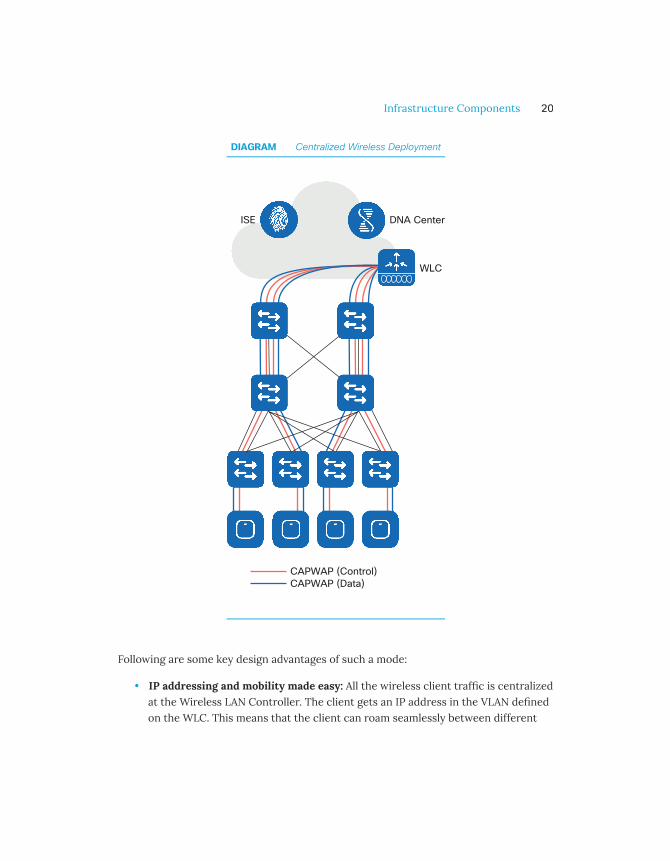
DIAGRAM Centralized Wireless Deployment
Following are some key design advantages of such a mode:
• IP addressing and mobility made easy: All the wireless client traffic is centralizedat the Wireless LAN Controller. The client gets an IP address in the VLAN definedon the WLC. This means that the client can roam seamlessly between different
Infrastructure Components 20

access points while keeping the same IP address. Also, there is no need to defineVLANs at the AP level.
• Single point of connection to the wired network: Since all client traffic iscentralized at the WLC, the switch port/ports where the controller is connectedrepresents a single point of attachment to the wired network. This makes itextremely easy to apply security or QoS policies to the wireless users.
• Simplified overlay design: Since traffic is tunneled from the AP to the WLCfollowing the Control and Provisioning of Wireless Access Points (CAPWAP)protocol, the wireless network becomes a network overlay to the wiredinfrastructure. This means that wireless can be deployed on top of any wiredinfrastructure.
SD-Access: integrating Wired and Wireless in Enterprise Campus
Software-defined Access Wireless brings the benefits of SD-Access Fabric to thewireless users. For a more comprehensive view on SD-Access-Wireless implementationplease see http://cs.co/9001D5thFhttp://cs.co/9001D5thFhttp://cs.co/9001D5thF
Simplifying the Control and Management Planes
SD-Access fabric creates a separation between the forwarding plane and the servicesplane. A robust, redundant, secure underlay network can be left untouched while all theservices are deployed on the overlay. This deployment is done using the orchestrationsolution called DNA Center, which simplifies the creation and management of the SD-Access Wireless network. All components, from SSIDs to policies, are created with a fewclicks.
The wireless control plane is still centralized at the Wireless LAN controller and thecontroller continues to provide functions such as client sessions management, RRM, APmanagement, and troubleshooting, just as in Centralized mode.
Infrastructure Components 21

Simplified policy
Network policy is a fundamental construct that helps to understand why SD-Access isrelevant. Network policies in an enterprise are heavily used, for example, to markpackets and apply QoS rules or enforce restrictions using ACLs.
The way these policies have traditionally been deployed is by leveraging the five-tuplein the IP packet header: source and destination IP addresses, ports and protocol. This isbecause the five-tuple is carried throughout the network, end-to-end. However, thisdependency of policy on the IP address and the VLAN constructs has made networksmore complex as they have grown in size over time. The reason for this complexity isthat the five-tuple doesn’t carry user or device information. However, policies areusually centered around rules applied to devices and users.
This results in what is called an IP address Overload because the IP address is beingused to identify the user and its location in the network. Every time a new policy isdefined for a category of devices or users, a mapping has to happen to identify theirassociated IP addresses. The dependency of policy on IP address may lead to complexACLs across many nodes of the network that track all the possible IP addresses for allpossible categories of devices, users, and applications.
SD-Access Wireless breaks this dependency by abstracting the policy definitions andseparating them from network constructs (IP address, subnet, VLAN, etc.). Thisabstraction helps simplify how networks are deployed. Policy is defined irrespective ofthe user or device IP address or VLAN. DNA Center is the single touch point for policydefinition and the SD-Access fabric nodes are the single points of policy enforcementas shown in the figure below.
Infrastructure Components 22

DIAGRAM SD-Access Enabled Wireless Network
Infrastructure Components 23

Seamless Roaming Domain
SD-Access Wireless architecture provides a way to segment the network withoutcomplicated technologies and also offers a way to stretch the client subnet withoutextending the same VLAN everywhere. The entire SD-Access fabric appears to theendpoints as if it were one big switch or one large roaming domain. This architectureoptimizes the data plane because the data is distributed.
DIAGRAM Wireless Roaming with SD-Access
Designing Distributed Branch Offices
Providing resiliency across the WAN
Branch offices are usually connected across an uncontrolled and unreliable WAN linkand inherently prone to the constraints of the WAN. FlexConnect is a Cisco wirelesssolution for branch and remote office deployments designed to overcome remote
Infrastructure Components 24
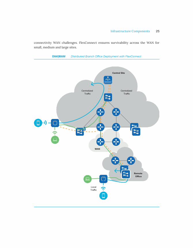
connectivity WAN challenges. FlexConnect ensures survivability across the WAN forsmall, medium and large sites.
DIAGRAM Distributed Branch O�ce Deployment with FlexConnect
Infrastructure Components 25
Optimizing Control and Data Planes
Since the majority of the resources at a remote site are local, the FlexConnect solutionenables the administrator to switch the client data traffic locally while centralizingcontrol traffic and management of APs. In the event of a WAN link or WLC failure, localtraffic continues to flow and roaming remains seamless. Centralized AP managementbrings a single pane for monitoring and troubleshooting, providing ease ofmanagement, and reducing the branch hardware footprint.
Efficiently upgrading access points across the WAN
Sites using FlexConnect APs are usually sensitive to WAN bandwidth consumption. TheFlexConnect Smart Image upgrade addresses this challenge by selecting a master AP ineach site and downloading the image only to that master AP, prompting all other APs inthe branch to download the code from that master AP. This reduces the time,probability of failure and bandwidth associated with image upgrades across the WAN.
Simple, affordable Enterprise Wi-Fi
Mobility Express is an Enterprise Class feature-rich solution that provides the ability torun the controller function on Cisco Access Points. It is well suited for small and mid-sized businesses with a limited number of access points. It is designed aroundconfiguration simplicity and an easy-to-use interface to allow for over-the-airmanagement and Day 0 seamless deployments.
Infrastructure Components 26

Wireless Network Automation
As more applications, users, devices, and services come onto the network, the growingcomplexity of ensuring that they all receive the appropriate level of service becomes achallenging and an expensive task. Reducing complexity and the associated cost arecentered around automation. For network administrators, automation means having anopportunity to minimize mundane operational activities and play a more strategic rolein the business; for the company, automation ultimately results in increasing speed tomarket and lowering of operational costs.
DNA Center Wireless Automation
Cisco DNA Center is the automation platform for the Cisco wireless solution and itsmain job is to translate the administrator's intent into meaningful device-levelconfigurations. DNA Center provides multiple levels of automation and orchestrationfor the different wireless deployment modes and greatly simplifies the network setupand initialization.
DNA Center Automation brings multiple benefits:
• Agility: Reduce the time required to design, deploy and/or optimize the wirelessnetwork. In the Design phase, the wireless administrator can quickly create ahierarchical site structure for each specific wireless deployment. DNA Centerautomation flow makes it extremely easy to then define settings (devicecredentials, network settings, etc.) and apply them globally or specifically to asite. This helps ensure consistency of configuration at scale.
• Reliability: Automation brings reliability by streamlining the configuration flowand provides consistent deployment of prescriptive "best practices". For example,when defining an SSID, the administrator has to specify only a few importantparameters; all the key best practice configurations are automatically applied inthe background.
• Simplification: DNA Center minimizes the management touchpoints. Forexample, the administrator uses a single pane of glass to define the desired policy
Infrastructure Components 27

between groups of wireless users. DNA Center integrates with Identity ServiceEngine (ISE) where the resulting policies are configured automatically.
• Abstraction: DNA Center uses easy-to-understand concepts and constructs thatabstract out the underlying feature and technology implementation specifics. Ifan SSID has to be broadcast only at a specific site, the administrator does notneed to deal with constructs such as WLAN IDs and AP Group, but simply assignsthe SSID and APs to a site, and the intent is translated to configurationsautomatically at the WLC.
Network Provisioning
In enterprise environments, initial network device setup is often done at a centralstaging area where the network admin installs the target system image and applies abasic standardized configuration. Once the device reaches its intended location, askilled person completes the installation and applies the final configuration. Thisprocess is time-consuming and expensive, error-prone and not very secure. Ciscosimplifies WLC and access point deployment with an easy-to-use initialization flow.
The WLC express setup simplifies the WLC provisioning process down to three easysteps and automatically enables industry-recommended best practices.
In case of access points, typically deployed in large quantity, the provisioning processbecomes an IT and operational challenge. Network Plug and Play (PnP) is a very simpleto use, scalable solution. PnP enables the administrator to provision devices from acentral site. Once the access points are installed, they are redirected during initialbootup to a PnP instance running either on-premise or in the Cisco public cloud. ThePnP service provisions the AP with the controller IP and individual settings that helpthe access point get setup without manual intervention, as shown in the diagram below.
Infrastructure Components 28

DIAGRAM Simplied AP deployment with PnP
Infrastructure Components 29

Resiliency in Wireless Networks
Wireless is mission critical and resiliency is the most important aspect of designing ahighly available wireless network. The main goal of resiliency is to reduce the networkdowntime and improve client experience.
In a wireless network, resiliency is not just about the Wireless LAN Controller but alsoincludes resiliency at the radio frequency (RF) layer and redundancy for solutioncomponents such as DNA Center, Prime and MSE/CMX. DNA Center redundancy isbuilt on the concept of multi-node clustering. Cisco Prime Infrastructure, MSE, andCMX use an Active/Standby model to maximize availability and minimize downtime.
Resiliency at Radio Frequency layer
Radio Frequency resiliency is about pervasive availability at the Physical Layer. Theadministrator should think about the RF layer as one of the most important foundationsfor the reliability of the network. If the foundations are not stable, the whole wirelessnetwork and client experience will be affected. This requirement translates into bestpractices for managing a wireless network based on the following components:
• Radio Resource Management (RRM) and Coverage Hole Detection and Mitigation(CHDM)
• Cisco CleanAir - identifying, classifying, and mitigating interferences
• Cisco ClientLink - improving client received signal (beamforming)
Cisco Radio Resource Management (RRM) and Coverage Hole Detection andMitigation (CHDM)
Radio Resource Management determines the optimal power and channel plan based onAccess Point layout and the reported information. A key component of RRM is theCHDM algorithm. The Access Point actively scans the air and continuously reportschannel load, interferences, and the client's received signal strength indicator (RSSI)info to the WLC. In an event when an Access Point (AP) fails and a coverage hole
Infrastructure Components 30

appears, CHDM algorithm kicks in and increases the power of neighboring radios,allowing clients to roam to neighboring APs.
For example, a manufacturing company with a large warehouse is having connectivityissues as stock levels change. The wireless signal might get blocked as stock levelsincrease, creating dead spots (coverage holes) and causing connectivity issues. CiscoRRM proactively monitors nearby access points (neighbors) and clients' receivedsignals, then dynamically raises the transmit power on nearby Access Points.
However, good features cannot compensate for bad design. The network should havebeen designed with redundancy in mind, with a proper site survey performed atoptimal AP power settings. Proper site survey implies that the same tool, the samewireless adapter and client device are used across the survey areas so that results arecomparable. Also, the wireless architect should design the network for the devices thatare actually going to be used: there is no point to optimize the coverage for high-endlaptops if most of the users will connect using a smartphone that has half thetransmitting power and fewer antennas.
Cisco CleanAir - Identifying, Classifying, Mitigating an interference source
Interferers not only can significantly lower the capacity and performance of thewireless network but also its availability by reducing the airtime for clients. In order toovercome this challenge, Cisco built an innovative solution, Cisco CleanAir. CleanAir canaccurately detect and identify interference sources impacting the wireless network.CleanAir provides a Spectrum Intelligence solution which can assess the impact ofinterferences and proactively change the channel when needed, allowing the AP andthe related cell and clients to continue to operate reliably.
Cisco ClientLink - Improving client received signal (beamforming)
In a wireless network, there are several types of wireless client devices. These could bea mix of new and old Wi-Fi technologies – 802.11ac, 802.11n, and 802.11a/g connections.To keep the older and slower clients from adversely impacting the performance ofnewer and faster 802.11ac connections, there is Cisco ClientLink.
ClientLink is a hardware-based beamforming capability built into Cisco Aironet wirelessLAN access points. When the access point concentrates signals toward the receiving
Infrastructure Components 31

client, that client is better able to “hear” the AP transmission, so throughput is higher.Client link enhances the performance in the downlink (AP to Client) direction. Theresult is an improved and more stable coverage for all clients.
Wireless LAN Controller High Availability
The next concern is to make sure that the brain of the wireless network is alwaysavailable. Wireless LAN Controller availability is provided by deploying multiplecontrollers. If one controller fails, the other can provide backup. The load can also bebalanced among controllers. Cisco Wireless supports two high availability (HA) modes,N+1 and Stateful Switch Over (SSO). Deciding which Wireless Controller redundancymodel depends on one simple aspect: what is the acceptable network downtime?
N+1 Wireless Controller Redundancy
In N+1 redundancy, each AP is configured with the IP address and name of theirpreferred Primary, Secondary and Tertiary WLCs. If the Primary WLC becomesunreachable, the AP will failover to its configured secondary WLC (then tertiary). Thisredundancy model is called N+1, which means that a WLC is available to support the APsif any primary WLC becomes unreachable. The main advantages of N+1 redundancymodel are as follows:
• Failover Predictability: the AP is preconfigured with a primary, secondary andtertiary controller; the network admin always knows where the AP will end up
• Flexible redundancy design options: N+N, N+1 and a combination of the two
• Geo-separated redundancy: redundant WLCs can be deployed across L3networks, for example across two data centers in different disaster recoveryareas
• 'Fallback' option in the case of failover: APs can be configured to go back to theprimary controller when it comes back up, or stay on the secondary
• Priority AP failover: if the secondary WLC gets oversubscribed, theadministrator can decide which APs are more important
The N+1 model can provide redundancy for Centralized, FlexConnect and SD-Accessdeployments. The Secondary/Tertiary WLC is managed independently and does not
Infrastructure Components 32
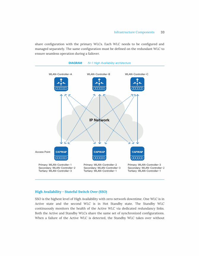
share configuration with the primary WLCs. Each WLC needs to be configured andmanaged separately. The same configuration must be defined on the redundant WLC toensure seamless operation during a failover.
DIAGRAM N+1 High Availability architecture
High Availability - Stateful Switch Over (SSO)
SSO is the highest level of High Availability with zero network downtime. One WLC is inActive state and the second WLC is in Hot Standby state. The Standby WLCcontinuously monitors the health of the Active WLC via dedicated redundancy links.Both the Active and Standby WLCs share the same set of synchronized configurations.When a failure of the Active WLC is detected, the Standby WLC takes over without
Infrastructure Components 33

impact on the network operations. Client information is also synced between WLCs andthus, client re-association is avoided when a switchover occurs, making the failoverseamless for the APs as well as for the clients.
SSO is supported across geographically separated Data Recovery Sites provided a lowlatency Layer 2 interconnection is established.
DIAGRAM Stateful Switchover High availability
Infrastructure Components 34

High Availability across the WAN
The FlexConnect Architecture has multiple features to build a resilient distributednetwork.
Protecting against WAN or WLC Failure
Access points in FlexConnect mode have the ability to function even when connectivityto the controller is lost.
The AP will continue to function with the last known configuration and traffic is locallyswitched so there is no disruption for existing clients. Fast Roaming keys are locallystored on the access point so roaming continues to work for clients that alreadyauthenticated. Additionally, the RADIUS servers can be configured per remote sitewhich makes the onboarding of new clients seamless even in the event of a failure.
Protecting against RADIUS Server Failure
Authentication is normally done using a common RADIUS server at the Central site.However, even in the event of RADIUS Server failure or central site outage, theFlexConnect architecture can continue to authenticate and onboard clients onto thewireless network using Local Authentication. With Local authentication, the APauthenticates new clients on a locally defined RADIUS server or an authenticationserver running natively on each access point in the branch. Existing clients stayconnected, do not re-authenticate and can also fast roam across the entire branch.
High Availability on Cisco Mobility Express
Cisco Mobility Express is a Wireless LAN Controller function embedded on an accesspoint. The AP which runs the Wireless LAN Controller function is called the Master AP.The Master AP election process determines which access point will be elected to runWireless LAN Controller function. In case of the failure of a current Master AP, theelection of the next Master is done automatically.
Infrastructure Components 35

Enhanced Experience through Partnerships
For each new release, Cisco Wireless networks are tested against hundreds of differentdevice types and applications. For each new version of major client operating systems,intensive tests are performed. The goal of these tests is to make sure that performanceis maintained or improved with every new major controller, access point, and clientsoftware release. Each time an issue is detected, Cisco engineers analyze the client andnetwork behavior to find the best way for the infrastructure to adapt and maintain theclient performance.
Cisco has customers in all geographical areas and all verticals. Cisco implements morefeatures than nearly any other network infrastructure vendor. At the same time, Ciscoparticipates in multiple industry forums to drive innovations intended to improve theperformance of Wi-Fi networks.
The benefit of partnerships with client and application vendors
In parallel, Cisco realizes that the network alone cannot provide all the answers. Eachclient implements specific logic to manage wireless traffic and network connections.Working with client vendors is an efficient way of ensuring that the featuresimplemented in the network infrastructure match the expectations of wireless clientsusing that network infrastructure. It is also a very powerful way to exchange views onexpected behaviors, Cisco bringing the “view from the network” and the vendor the“view from the device”. The result is always a better network and a better networkexperience for the end user. However, such effort is demanding, requiring deeperoptimizations of the AP and WLC codes, and resolution of apparent conflicts of viewsbetween client-vendor behaviors. Cisco has the breadth to undergo these exchangesand optimizations, while most other vendors stop at generic behaviors.
Apple partnership
An example of such a powerful partnership is Apple and Cisco. The alliance started in2015 and produced a large set of features for improved performances for voice andvideo communications, security, analytics and Wi-Fi experience, for Apple device users
Infrastructure Components 36

on Cisco networks. In the Wi-Fi space, the result of this partnership is secure, fasterand more efficient roaming. Multiple measurements have shown a tenfold increase inroaming speed with these enhancements, enabling seamless roaming while on a voicecall. In the field of QoS, the partnership also enables enterprises to ensure that thenetwork QoS is also reflected in the air, including in the client-to-AP direction. For thefirst time, QoS has become really end-to-end, even with Wi-Fi access networks.
The Apple-Cisco partnership demonstrates what is possible by working together. Ciscooptimizes the network behavior for multiple chipset and other vendors. The samedialog and optimizations occur for software solutions and applications vendors, such asMicrosoft (Lync/Skype for Business, and so on).
Infrastructure Components 37

Radio Excellence

Introduction
The Dynamic Workspace
In an information-centric economy, mobility is centered around a key concept: work issomething you do, and not necessarily a place you go. In other words, productivity isoptimized when users can work wherever and whenever they need.
The most important element for such mobility is an available, reliable, and securewireless LAN (Wi-Fi) connection. This ensures that everyone has the capacity they needto be productive with any application, from the web and cloud service access to real-time streaming video and voice.
Within the enterprise, open workspaces encourage collaboration, communication, andteam-based productivity. Wireless is becoming the critical and preferred way toconnect. The baseline requirement for an efficient open workspace is to guarantee notonly ubiquitous Wi-Fi coverage but also capacity everywhere. A reliable, secure, andscalable network is critical. However, the individual radios need to be coordinated infrequency and power to provide a seamless and consistent experience for the users.Environments are often not isolated, meaning that there will be neighboring wirelessnetworks using the same channels as the local access points. Each access pointrepresents a finite amount of bandwidth potential in a given cell. More capacity meansmore radios in closer proximity. Optimal channel selection, bandwidth assignment, andpower coordination become critical.
To achieve this goal, Cisco has brought multiple innovations:
• Infrastructure: Cisco Aironet 802.11ac Wave 2 access points for higherthroughput (up to 5Gbps)
• Beamforming: Enhanced implementations of beamforming technologies (MU-MIMO), so that multiple clients can simultaneously receive transmissions from asingle access point.
• Centralized Radio Resource Management to provide holistic RF optimizationacross the network
Radio Excellence 39

• Flexible Radio Assignment (FRA) to ensure that dual-radio APs form micro andmacro cells that will maximize capacity for all clients.
• Dynamic Bandwidth Selection (DBS) to optimize the channel width on each AP.
• CleanAir to detect and classify non-Wi-Fi interferers and neighboring Wi-Fisignals.
Radio Excellence 40

High Density Experience (HDX)
Some of the innovations that Cisco has introduced over the years come directly fromthe use case of increasing capacity and client density. These innovations are collectivelygrouped under the name Cisco High Density Experience (HDX).
ClientLink
Cisco ClientLink was the industry's first implementation of beamforming back in days of802.11n. The primary purpose is to use an additional transmitter to enhance theperception of the received signal at the client by forming the transmitted elements intoa focused beam. This is transmit beamforming (TxBF).
The 802.11n standard allowed for beamforming. However, there was no standardmethod adopted by access point and client manufacturers. In this gap, Cisco took theinitiative to develop a beamforming method which benefited not just 802.11n clients, butalso legacy 802.11a/g clients that were the slowest on the network. This was significantat the time since most of the network was still populated by legacy clients. The effect ofClientLink is to improve the client's Signal-to-Noise Ratio (SNR) in the downlinkdirection by 3-6 dB, enabling the client to maintain a higher data rate for longer. Thefigure below depicts this advantage. When ClientLink is enabled, the available data ratestays at 1300 Mbps throughout the floor, while without ClientLink, such a data rate isonly available close to the AP. Since most of the traffic flows downstream, this directlytranslates into a more efficient use of airtime.
Radio Excellence 41
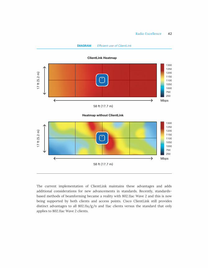
DIAGRAM E�cient use of ClientLink
The current implementation of ClientLink maintains these advantages and addsadditional considerations for new advancements in standards. Recently, standards-based methods of beamforming became a reality with 802.11ac Wave 2 and this is nowbeing supported by both clients and access points. Cisco ClientLink still providesdistinct advantages to all 802.11a/g/n and 11ac clients versus the standard that onlyapplies to 802.11ac Wave 2 clients.
Radio Excellence 42

Flexible Radio Assignment (FRA)
Network implementations have grown denser over time to keep up with capacityrequirements. As more APs are added within the same area, channel separationbecomes even more important to ensure that the RF network runs efficiently.Traditional APs are dual-band, meaning that they have a dedicated 2.4 GHz and adedicated 5 GHz radio. The problem is that 2.4 GHz is a limited spectrum and onlycontains 3 usable channels. When creating a dense 5 GHz network (using up to 25channels), interference in the 2.4 GHz space is inherently created. In response to thisissue, Cisco created a Flexible Radio AP which allows a dual-band radio to be used formultiple beneficial roles within the network, instead of being limited to 2.4 GHz service(which often was simply turned off to solve the above problem). The Flexible RadioAssignment algorithms then use RRM's RF maps to evaluate the coverage in 2.4 GHz andidentify radio resources which are not needed.
FRA first identifies redundant interfaces, and then calculates and manages theassignments. For instance, FRA can choose to re-assign the redundant radio as asecond 5 GHz interface on the AP (instantly doubling the capacity within the cell). If 5GHz is already at peak efficiency, a monitor role can be assigned to that Flexible Radio.A monitor radio is a dedicated scanning radio and benefits security, location services,and even RRM's resolution on the network. FRA brings the ability to solve coverageproblems in multiple creative ways and is an example of how RRM continues to evolveto solve problems.
Radio Excellence 43

DIAGRAM FRA Client Aware radio role allocation
One way FRA and the Flexible Radio are used is in a mode called Client Aware,illustrated in the figure above. In this scenario, a company has a large event in an openspace area which usually only receives a mild volume of traffic. Because this areadoesn't normally require a lot of Wi-Fi capacity, most Flexible Radios have beenassigned to a monitor role. The event brings more users than usual. Client Awaremonitors the dedicated 5 GHz radio and when the client load passes a pre-setthreshold, automatically changes the Flexible Radio assignment from a monitor roleinto a 5 GHz role, effectively doubling the capacity of the cell on demand. Once thecapacity crisis is over and Wi-Fi load returns to normal, the radios resume theirprevious roles.
DBS and FlexDFS
As Wi-Fi has progressed, evolving 802.11 standards have increased capacity and speedby allowing the use of wider channels by assigning 2 or more together. This is known asChannel Bonding. 802.11n could use 2x 20 MHz channels to create a 40 MHz superchannel. 802.11ac enabled the ability to use 80 MHz (4x 20 MHz channels) or even 160MHz (8x20 MHz channels). When 40 MHz, or 80 MHz bandwidths are chosen, APs
Radio Excellence 44

require 2 or 4 channels for every interface. If you do not have enough channels to keepthe access points isolated in frequency, the APs suffers from self-interference. Evenmore problematic, 802.11n supports 40 MHz-wide channels and 802.11ac supports 160MHz. 160 or even 80 MHz is largely wasted if the clients are all 802.11n since they canonly use 40 MHz of that channel.
To ensure more efficient allocation of bandwidth, Cisco created Dynamic BandwidthSelection (DBS) which adds an algorithm to the RRM Dynamic Channel Assignment(DCA suite) that tracks the client types, as well as real-time media use (voice, video) foreach radio, and automatically assigns the right bandwidth for the cell, based on therequirements of the clients. This allows the channels to be created as needed andpreserves critical channel spacing to maintain cell separation and avoid interference.
For example, a large enterprise has a dense Wi-Fi network encompassing severalcollocated Wi-Fi Access Points. These access points cover multiple floor areaspertaining to different client densities and capabilities and require more or lesscapacity and speed. With limited Wi-Fi spectrum, can these radios automatically beconfigured in order to meet site-specific demands? DBS automatically switches radiosinto narrower or wider channel widths. This way, when the network load is lower, DBSautomatically fine-tunes radios on lower bandwidths to reduce RF contention andexpands their bandwidth as the capacity needs changes in future.
Flex DFS solves a different problem that was introduced along with 802.11n and 802.11acbonded channels. According to the DFS rules, if a station detects a radar on its channel,then the station and clients must abandon the channel and defer to the radar. That'sfine if the "channel" is only 20 MHz. But if that channel is 40, 80, 160 MHz - that’s a lotof spectrum being left on the table for a radar that likely only impacted a single 20 MHzsegment. Enter Flex DFS.
Cisco DFS detection mechanism identifies a radar operating frequency with aresolution of 1MHz and also identifies which specific 20 MHz channel segment isimpacted by the radar. Relying on DBS, the system is then free to re-assign the channelbandwidth to avoid the radar and to maintain the remaining channels that are notimpacted for use by the system. An 80 MHz channel is 4 x 20 MHz segments. If a radaris detected on any of the 4 segments, potentially the full 80 MHz is blacklisted (notallowed to be used) for 30 minutes minimum. With FlexDFS, the channel bandwidth can
Radio Excellence 45

be dynamically reduced to 40 MHz, blacklist will list the affected channel, and there willstill be a 20 MHz channel available to the rest of the system.
BandSelect and Load Balancing
Most Wi-Fi devices are dual-band capable, which means that they are capable ofconnecting on 2.4 and 5 GHz. However, many of these devices prefer, for any number ofreasons, to connect on the more congested 2.4 GHz band instead of the preferred 5GHz band. This diminishes the quality of experience for the users of that cell. The clientalone makes the determination on which band to use. Some of these clients have overlysimplified logic and simply prefer the band that is loudest. 2.4 GHz propagates fartherthan 5 GHz, so is extremely attractive under these criteria. To avoid this default choiceof the 2.4 GHz band, by enabling Cisco Band Select, clients can to be encouraged orsteered to the 5 GHz band. Band Select identifies true single band clients and separatesthese from dual-band capable clients. If a dual-band client attempts to connect to the2.4 GHz interface, the 2.4 GHz probe response is delayed and 5 GHz probe responsesare sent, steering the client to 5 GHz.
For example, in a classroom, the instructor is using a presentation remote [an 802.11b/gcustom device] to have students submit answers in real time. Due to spectrumconstraints on the 2.4 GHz network, simultaneous use of a presentation remote andwireless laptop results in a poor Wi-Fi connectivity experience on student’s laptops.The classroom has enough capacity on the 5 GHz network, but most of the laptopclients are connected on 2.4 GHz. Cisco BandSelect performs a holistic inspection ofthe associated clients and then offloads Dual-Band Clients onto the 5 GHz spectrum.This way, legacy clients (including the presentation remote) can continue to operate on2.4 GHz while wireless laptops (mostly dual-band) can be steered towards 5 GHz toensure better capacity and performance needs.
In high-density deployments with a large number of APs and clients, sometimes theload distribution between APs turns out to be uneven. This is largely a function of theclient devices. Client load balancing is a feature that attempts to balance the client loadbetween APs in the network. In the figure below, the AP on the right is overloaded andrefuses the new client. That client then successfully joins the AP on the left, where theload is lower.
Radio Excellence 46

DIAGRAM Client Load Balancing
Radio Excellence 47

Mitigating Interferences
Cisco CleanAir
Cisco CleanAir technology is a solution that provides proactive, high-speed spectrumintelligence across 20, 40, 80, and 160-MHz-wide channels to accurately measure Wi-FiChannel quality and identify non-Wi-Fi sources of interference. Non-Wi-Fi interfererscan be tricky to detect and at the same time can consume partial or sometimes thecomplete spectrum and reduce access point capacity. With the proliferation of devicessuch as access security cameras and Bluetooth-enabled devices, more and more ofthese interferers are operating within the cell boundaries of Wi-Fi access points.
Unlike competitors who use purely software-based interferer detection, Cisco has builtcustomized silicon to enable full spectrum analysis (see hardware innovations section)and integrated this hardware capability into its access points. Cisco CleanAir AccessPoints can detect 25 distinct types of interference, and track hundreds of individualinstances of such types per radio. Beyond the ability to detect, the information needs tobe actionable. Understanding the potential impact of a given interference sourcerequires context. For this, the ability to map the source location in relation to theresources of the network was created to provide context. In the illustration above,several access points are on the same channel. Cisco CleanAir identifies which APs areaffected by the interferer. A visualization software, such as Cisco Prime Infrastructureor CMX, can be used to represent the zone of impact.
For example, a company has remodeled and moved to an open office environment usingWi-Fi as the primary medium of access. However, wireless connectivity issues (slowthroughput and disconnections) are occurring during certain times of the day. CiscoCleanAir is able to identify two sources of interference, a leaky microwave oven in thelunchroom and a 5 GHz transmitter that is being used to extend a video surveillancecamera feed. CleanAir mitigates interferences by moving the AP away from the highutilization channels. The IT administrator is alerted and is able to replace the defectiveoven and eventually move the camera to a wired connection.
Radio Excellence 48

Hardware Innovations
Introduction
As technology keeps evolving at an always faster pace, features that may have beenrelevant 5 years ago may become obsolete next year. In order to continuously offerfeature and product excellence, Cisco has made the choice to innovate both inhardware and software. Innovative and in-house developed hardware provides a strongand flexible foundation on which innovative software can be developed.
This allows for tighter integration between the hardware and innovative features thatwork consistently and reliably for any situation. With off-the-shelf hardware, vendorsare limited to a set of pre-existing ‘good enough’ features. With customized hardware,Cisco engineers have unparalleled flexibility to evolve functions of access points andwireless LAN controller as new challenges appear.
Hardware Innovations 50

Dual 5 GHz Radio
With the proliferation of 802.11ac wave 2 devices and increasing application capacityrequirements, a single 5 GHz radio often isn’t enough to handle a high density ofwireless multimedia devices and related network load. The Flexible Radio Assignment(FRA) technology integrated into Cisco Aironet 2800, 3800, and 4800 Series AccessPoints enables revolutionary dual 5 GHz operation on demand. Implemented along witha multigigabit Ethernet connection, FRA doubles the capacity of a single Wi-Fi accesspoint without requiring additional cabling support. Dual 5 GHz not only increases RFcapacity, but its innovative design equips each access point for efficient spectrumusage.
Embedding dual 5 GHz radios on the same platform is not only an innovative hardwaredesign but an industry-first design. Traditionally, the ability to co-locate “same band”radios in close proximity is a challenge due to the required radio signal isolation neededbetween the two radios. Without this isolation, the radio link can suffer frominterference due to the adjacent same band radio.
Cisco Aironet 802.11ac Wave 2 Series Access Points can overcome the signal isolationchallenge differently for their internal antenna and external antenna models. On theexternal antenna model, the Access Point includes an additional hybrid RF-DigitalSmart Antenna connector as shown in the picture below, that can be used as for anexternal 2.4 GHz or a second 5 GHz data radio antenna. Having the ability to connect avariety of external antennas to dual radios with a simple click is in itself an industry firstand leverages Cisco innovative FlexPort feature. With the Smart Antenna connector, aninstaller can connect multiple complementary 2.4 GHz and 5 GHz antennas in a non-obtrusive way that preserves and enhances the signal isolation and reduces theinstallation complexity.
Hardware Innovations 51

DIAGRAM Smart Antenna connector detail
The internal antenna access point models have the added isolation challenge that theantennas must all co-locate physically within the same housing. In order to do this,Cisco chose to implement a micro/macro design. This design effectively creates a cellwithin a cell. The solution includes antenna polarity diversity, channel/frequencydiversity, and enforced power allocation limits. The antennas for the “macrocell” havestrong vertical polarization and are designed to provide high gain to clients on thehorizon. In the same two dimensional plane, the "micro" set of antennas provides astrong horizontal polarization, resulting in high signal isolation between the two sets ofantennas at 5 GHz. The illustration below represents overlaid radiation patterns of themicro and macro cells.
Hardware Innovations 52

DIAGRAM Microcell and macrocell radiation patterns
Reducing the transmitter power of the microcell reduces the radio signal level noisefloor received at the macrocell, which effectively limits the interference. In turn, theeffect of the macrocell’s transmitted noise floor on the receiver of the microcell isminimized because the range of the coverage of the microcell is reduced. In typical Wi-Fi deployments, an access point serves clients both near and far associatedsimultaneously (multiplexed) over time. With the macro/micro approach, the accesspoint can serve near clients with the microcell at the same time it serves distant clients,resulting in as much as a double the total AP capacity, as illustrated in the figure below.Cisco has also developed innovative techniques to steer the clients between microcellsand macrocells.
Leveraging this innovation requires no additional knowledge or changes in the way thewireless network is designed and deployed, as the cell size remains the same as withtraditional dual-radio cells. Cell capacity doubles with no additional management ordeployment overhead.
Hardware Innovations 53

Modularity
The 802.11ac Wave 2, Cisco Aironet 3800 Access Point supports a module port for futureexpandability. The module port along with the Cisco Aironet Developer Platform (ADP)enables developers to easily prototype both hardware and software applications basedon readily available development platforms. The ADP includes a reference hardwaredevelopment kit (HDK) which interfaces with the access point. The HDK providesEthernet and power connectivity as well as support and mounting accommodations formany of the popular development platforms such as Raspberry Pi, Intel Next Unit ofComputing (NUC), and others.
Developers can also create custom modules that plug into the AP expansion moduleconnector port as illustrated in the figure below. Possible modules could be devicessuch as BLE readers, Electronic Shelf Labeling (ESL), physical security, camera sensorgateways, LED lighting, and potentially other radio hardware based on technologiessuch as 802.11ad (60 GHz), 3.5 GHz (Citizens Broadband Radio Service - CBRS), etc. Inanticipation that some developers may design cellular radio modules for the AP-3800,Cisco has incorporated cellular filtering into the design of the AP for module isolation.
DIAGRAM AP modularity
Hardware Innovations 54

Without such modularity options, developers would need to build a custom solutionbased on an access point board, increasing development time and cost. Additionally,separate infrastructure elements would need to be built to provide connectivity andpower. With AP modularity, Cisco has made the process simple and cost-effective.
Hardware Innovations 55

MultiGigabit (mGig)
Cisco MultiGigabit technology delivers speeds up to 10 Gbps on existing Category 5e/6cables. The technology also supports Power over Ethernet (PoE), PoE+, and CiscoUniversal PoE (UPoE) to avoid installing new electrical circuits to power the 802.11acWave 2 access points. Cisco is a founding member of the NBASE-T Alliance created in2014 and has provided thought leadership to develop the technology and ratify thestandard. Cisco has a wide range of mGig capable switches.
Here are main benefits of mGig:
• Multiple speeds: Cisco mGig technology supports auto-negotiation of multiplespeeds on switch ports (100 Mbps, 1 Gbps, 2.5 Gbps, and 5 Gbps on Category (Cat)5e cable; and up to 10 Gbps over Cat 6a cabling), as illustrated in the figure below.
• Cable type: The technology supports a wide range of cable types including Cat5e, Cat 6, and Cat 6a or above.
• PoE power: The technology supports PoE, PoE+, and UPoE (up to 60W) for all thesupported speeds and cable types, providing Access Points with additional powerfor advanced features such as hyperlocation and modularity.
DIAGRAM Cisco MultiGigabit (mGig) using NBASE-T
Hardware Innovations 56
Cisco Aironet 3800 and 4800 series Access Points support Cisco Multi Gigabittechnology and provide up to 5 Gbps. This technology protects the investment in thecabling infrastructure, allowing for new and faster 802.11 technologies to be transportedover the same physical Ethernet infrastructure.
Hardware Innovations 57

CleanAir-SAgE
Interference is a challenge for Wi-Fi deployments, because multiple technologiescompete for the same shared unlicensed spectrum. New sources of interference appearall the time. Interference affects the usable bandwidth of the entire cell, making it animportant issue to solve.
Wi-Fi chipsets categorize received signals into two basic categories: Wi-Fi signals thatthe Wi-Fi chipset understands, and noise (any energy that it doesn’t understand). Non-Wi-Fi sources of interference are all seen as noise.
The Spectrum Analysis Engine (SAgE), integrated into the Cisco Aironet access points, isspecifically designed to identify sources of non-Wi-Fi interference, at the highestresolution, in the most simple and effective way.
There are no other integrated spectrum analyzers similar to Cisco SAgE on the market.There are handheld analyzers, however, the skillset required to operate them is highlyadvanced and mandates a local operator. In the years since this SAgE integration, Ciscohas continued to innovate in the field of non-Wi-Fi interference management anddetection:
• BLE detection has been added, enabling any Cisco CleanAir AP to also log andclassify BLE signals. That capability was added to HyperLocation to provide asolution for Angle of Arrival (AoA) for both Wi-Fi and BLE.
• Similarly, Cisco SAgE was the first in the industry to perform sub-milliseconddetection of radar signals.
Performing such detection in software with a standard Wi-Fi chipset does not providethe scanning resolution required to achieve accurate and granular interfere detectionand isolation. This is critical to make the right channel allocation decision.
Hardware Innovations 58

Innovative AP Deployment Solutions
In order to ensure a consistent quality of experience to the users, Wi-Fi infrastructurehardware needs to be adaptable to a wide range of physical installations. For instance, amanufacturing plant deployment is very different from a carpeted office. Cisco providesflexible options to meet the challenging physical requirements.
Specialty Antennas
The Internal Antenna AP model is optimized for carpeted office space where the ceilingmay not exceed 12ft/3.5m. Given the physical nature of RF, performance degrades withdistance from the AP. When the deployment requires an antenna position beyond12ft/3.5m, other antenna designs might be required. Cisco offers various antennadesign options to provide consistent coverage and performance regardless of thephysical installation requirements.
When the application requires dual 5 GHz macrocells, for example, an antenna indoorsand one outdoors, or perhaps two different RF coverage cells within an auditorium, themodel to be used would typically be an access point such as the 2800e or 3800e with anExternal Antenna. Different types of Directional Antenna can be used. Environmentssuch as very high ceilings, long corridors and/or manufacturing areas are places wherethe need to focus the energy in a given direction is desirable.
Hyperlocation Antenna arrays are unique antennas designed specifically for trackingclient location with high accuracy, using Angle of Arrival (AoA). Cisco 4800 Access Pointintegrates the Hyperlocation Antenna directly within the AP. The 4800 Access Point alsoprovides a dual 5 GHz macro-micro cell antenna system along with an intelligentanalytics radio that processes location and packet analysis. Using this hyperlocationantenna array, integrated analytics radio troubleshooting becomes much easier.
Hardware Innovations 59
Models with Flexible Antenna Ports
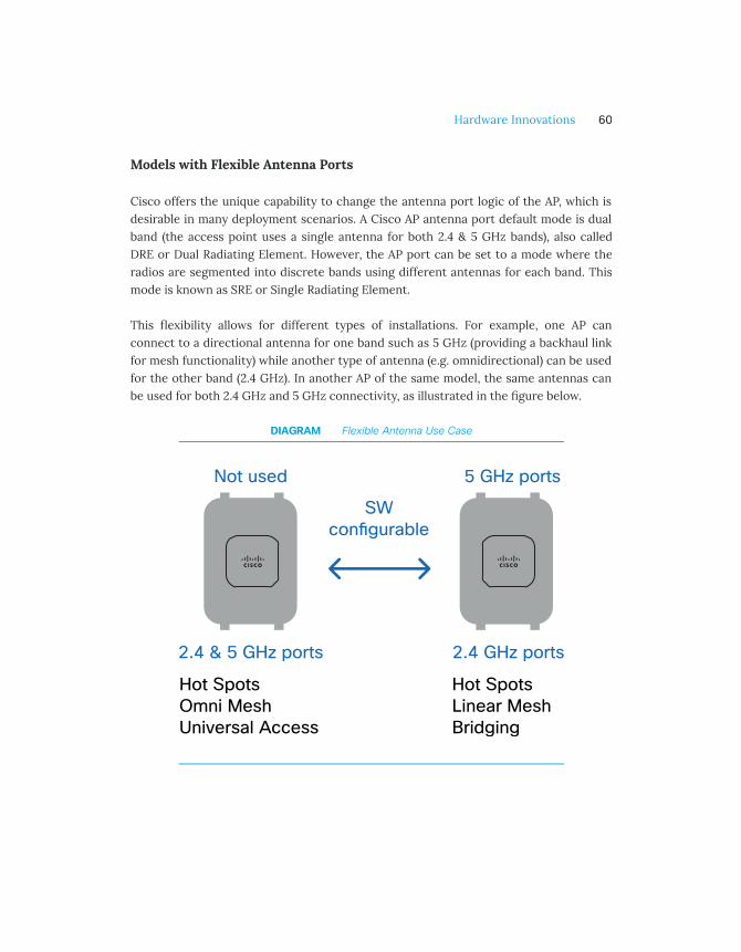
Cisco offers the unique capability to change the antenna port logic of the AP, which isdesirable in many deployment scenarios. A Cisco AP antenna port default mode is dualband (the access point uses a single antenna for both 2.4 & 5 GHz bands), also calledDRE or Dual Radiating Element. However, the AP port can be set to a mode where theradios are segmented into discrete bands using different antennas for each band. Thismode is known as SRE or Single Radiating Element.
This flexibility allows for different types of installations. For example, one AP canconnect to a directional antenna for one band such as 5 GHz (providing a backhaul linkfor mesh functionality) while another type of antenna (e.g. omnidirectional) can be usedfor the other band (2.4 GHz). In another AP of the same model, the same antennas canbe used for both 2.4 GHz and 5 GHz connectivity, as illustrated in the figure below.
DIAGRAM Flexible Antenna Use Case
Hardware Innovations 60
Access Point Enclosures
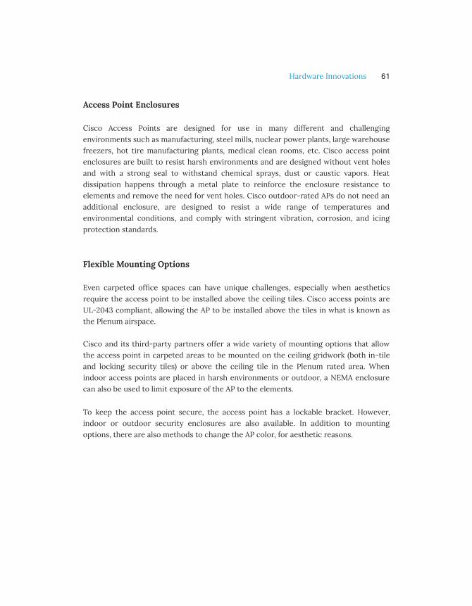
Cisco Access Points are designed for use in many different and challengingenvironments such as manufacturing, steel mills, nuclear power plants, large warehousefreezers, hot tire manufacturing plants, medical clean rooms, etc. Cisco access pointenclosures are built to resist harsh environments and are designed without vent holesand with a strong seal to withstand chemical sprays, dust or caustic vapors. Heatdissipation happens through a metal plate to reinforce the enclosure resistance toelements and remove the need for vent holes. Cisco outdoor-rated APs do not need anadditional enclosure, are designed to resist a wide range of temperatures andenvironmental conditions, and comply with stringent vibration, corrosion, and icingprotection standards.
Flexible Mounting Options
Even carpeted office spaces can have unique challenges, especially when aestheticsrequire the access point to be installed above the ceiling tiles. Cisco access points areUL-2043 compliant, allowing the AP to be installed above the tiles in what is known asthe Plenum airspace.
Cisco and its third-party partners offer a wide variety of mounting options that allowthe access point in carpeted areas to be mounted on the ceiling gridwork (both in-tileand locking security tiles) or above the ceiling tile in the Plenum rated area. Whenindoor access points are placed in harsh environments or outdoor, a NEMA enclosurecan also be used to limit exposure of the AP to the elements.
To keep the access point secure, the access point has a lockable bracket. However,indoor or outdoor security enclosures are also available. In addition to mountingoptions, there are also methods to change the AP color, for aesthetic reasons.
Hardware Innovations 61

Infrastructure Security
Introduction
With the proliferation of IoT and wireless-enabled devices, wireless network security isvital. Businesses around the world risk billions of dollars every year due to securitybreaches, ransomware and other network attacks.
Cisco provides a solid set of best practices features to secure the wireless network. Theunique Cisco approach to security turns each element in the network into a securitysensor and monitoring system, giving a powerful and scalable solution for gaining deepvisibility into threats within the network space, building a first line of defence. Theinsights into security analytics are streamed constantly from the network directly toDNA Center. These insights continuously monitor the network conditions andautomate policies to ensure business intent is fulfilled and the network is secure.
Securing the wireless network includes securing the client with policies, and securingthe infrastructure, as shown in the diagram below. This second element includes thefollowing components:
• First secure the network by implementing Cisco Trustworthy systems,centralized encryption, and guest traffic segmentation.
• Second, secure the air with Cisco CleanAir Technology and Cisco aWIPS solution.
Infrastructure Security 63

DIAGRAM Wireless integrated security
Infrastructure Security 64
Securing the Network
Wireless security is a combination of hardware and software technologies designed toprotect the network. An effective approach to network security covers multiple layers:
Securing the network elements
Securing the transport
Securing the Network Elements
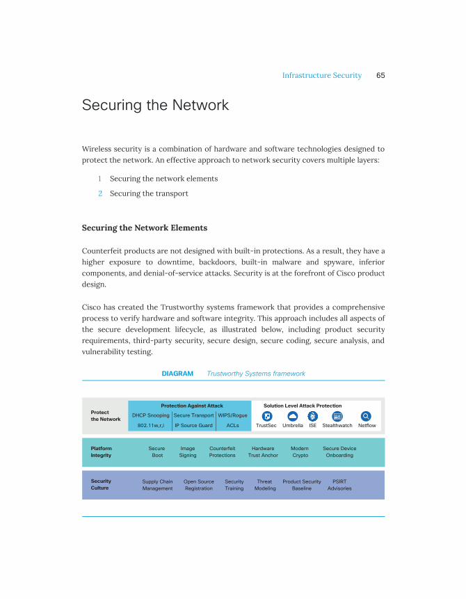
Counterfeit products are not designed with built-in protections. As a result, they have ahigher exposure to downtime, backdoors, built-in malware and spyware, inferiorcomponents, and denial-of-service attacks. Security is at the forefront of Cisco productdesign.
Cisco has created the Trustworthy systems framework that provides a comprehensiveprocess to verify hardware and software integrity. This approach includes all aspects ofthe secure development lifecycle, as illustrated below, including product securityrequirements, third-party security, secure design, secure coding, secure analysis, andvulnerability testing.
DIAGRAM Trustworthy Systems framework
1
2
Infrastructure Security 65
Cisco Secure Development Lifecycle
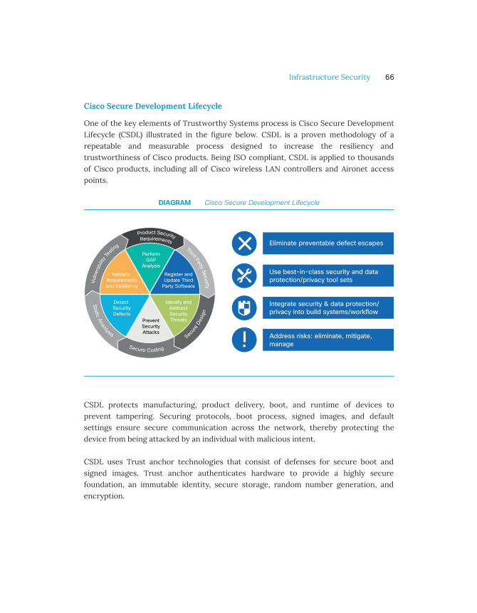
One of the key elements of Trustworthy Systems process is Cisco Secure DevelopmentLifecycle (CSDL) illustrated in the figure below. CSDL is a proven methodology of arepeatable and measurable process designed to increase the resiliency andtrustworthiness of Cisco products. Being ISO compliant, CSDL is applied to thousandsof Cisco products, including all of Cisco wireless LAN controllers and Aironet accesspoints.
DIAGRAM Cisco Secure Development Lifecycle
CSDL protects manufacturing, product delivery, boot, and runtime of devices toprevent tampering. Securing protocols, boot process, signed images, and defaultsettings ensure secure communication across the network, thereby protecting thedevice from being attacked by an individual with malicious intent.
CSDL uses Trust anchor technologies that consist of defenses for secure boot andsigned images. Trust anchor authenticates hardware to provide a highly securefoundation, an immutable identity, secure storage, random number generation, andencryption.
Infrastructure Security 66
In addition, during the production lifecycle, ongoing security testing including probesand attacks validates the following key elements:
• Integrity and robustness of the protocols that are implemented in the product
• Which ports and services are enabled by default
• Resistance to common attacks and scans by common open source andcommercial hacker tools.
All Cisco Aironet wireless LAN controllers and access points have gone through theextensive CSDL process to ensure highest security posture and resiliency. All CiscoAironet wireless products have the following global government certifications:
• FIPS: Federal Information Processing Standards
• CC: Common Criteria for Information Technology Security Evaluation
• UCAPL: Department of Defense’s (DoD) Unified Capabilities Approved ProductsList
• CSfC: National Security Agency's (NSA) Commercial Solutions for Classified
Securing the access point
Access Points (AP) need to be placed in open and common areas where the clients arelocated and hence they are necessarily more physically accessible than controllers,switches or routers. APs need extra protection and Cisco provides a unique capabilityfor reaching this objective:
• AP placement: using external antennas, Cisco APs can be hidden so they don’tattract attention.
• Physical security: Cisco AP offers a secure lockable bracket to fix the AP to themounting infrastructure so the AP cannot be taken down and tampered with.Consider lockable enclosures (designed for wireless AP) to hide APs as needed.
• LED mode: Disable the LED indicator to limit the visual attraction of APs.
In addition to physical security, Cisco has some distinctive capabilities to protect thecommunication between APs and WLC such as:
Infrastructure Security 67

• 802.1X Supplicant: Access points can be authorized to the network using 802.1Xsupplicant, with various EAP methods (EAP-FAST, EAP-PEAP and EAP-TLS). For ahigher level of security, Cisco APs authenticates against RADIUS servers wherethe AP credentials and certificates are stored. This way, unauthorized devicescannot connect to the network on the AP switch port.
• Certificate-based join process: During the join process, Cisco Aironet accesspoints and controllers verify each others' identity using either a ManufacturerInstalled Certificate (MIC) or Self-Signed Certificate (SSC). Also, during the joinprocess, both AP and WLC derive a security key that is used to encrypt thecontrol plane channel so that any configuration and management exchanges aresecure.
• Secure certificate: Cisco access points leverage Secure Unique Device Identifier(SUDI) certificates. SUDI is a X.509 compliant device certificate burned into thedevice's secured chip (ACT2) during manufacturing. The SUDI certificate containsthe device's serial number, private-public keys, and the Cisco CA signature. It’simpossible to access this secure information even if an AP is lost or stolen.
• AP Policy: Access points can also be restricted from joining a controller based onuser-defined AP Policies. These are rules based on the type(s) of certificates thatthe WLC would accept (SSC, MIC, LSC) when authorizing APs against a local orremote authority such as RADIUS.
Now that the wireless network infrastructure is secured (AP, WLC), protecting clientdata traffic across the network is also critical.
Securing the Transport
Most access points are deployed in a secure network within a company building, sodata protection is usually not necessary. In contrast, for teleworkers, the trafficbetween an home office access point and the controller travels through an unsecuredpublic network; or sometimes the network admin may have no control on the wiredinfrastructure used as transport. For these scenarios, the Cisco wireless solution hasthe distinctive capability of protecting the integrity of the client data as it traversesunsecured wired networks.
Infrastructure Security 68

Datagram Transport Layer Security (DTLS) Encryption
Data and control traffic between the AP and the Wireless LAN controller use differenttunnels, as illustrated in the picture below. Access point control traffic exchanges withthe controller is always encrypted. Client data forwarded to the controller can beencrypted with DTLS.
DIAGRAM Wireless control and data tra�c tunnels
However, over-the-air encryption for client traffic is managed at the access point level,adopting a distributed model (AP-based) instead of centralized one (controller-based).Two main considerations have driven this choice:
• Packet encryption optimization: 802.11 frame aggregation is negotiated betweenthe AP and the client. When encryption is performed at the AP level, the AP andclient can negotiate the right aggregate size, and the AP can then encrypt theentire aggregate. When encryption is performed at the WLC, such flexibility islost. As a result, aggregation loses efficiency.
• Increased Security: In a centralized encryption deployment, it could be possibleto spoof a client MAC address and send encrypted packets with a wrong key. Ifthe AP is not processing the frame, it will have no way to know if the packets areencrypted correctly and will blindly pass them to the WLC. This will result in aDoS attack, where the controller will have to process and discard all themalformed frames. By distributing the encryption, the AP will drop these packetsright away and protect the whole network from these attacks.
Infrastructure Security 69

Guest Anchor
Guest traffic needs to be secured and separated from the corporate enterprise network.An element of such isolation is to forward guest traffic to dedicated anchor controllerslocated in the demilitarized zone (DMZ), as illustrated in the figure below.
DIAGRAM Secure Isolation with Guest Anchor
Infrastructure Security 70

Guest traffic is received on the access points, forwarded to the foreign controller, andtunneled automatically to the anchor controller. Traffic between controllers can also beencrypted. This topology provides a clear separation (or isolation), as guest trafficcannot make its way back to the corporate network through the firewall, and is onlyforwarded to the Internet. Any risk for malicious activity that may occur is constrainedwithin the non-trusted area. Cisco guest anchoring provides an additional level ofsecurity and performance, since anchor controllers can be solely dedicated tosupporting guest access functions (providing guest tunnel termination), and not usedfor managing access points in the enterprise.
Anchor controller redundancy can also be built into the design to add an additionallayer of reliability for guest services. If an active anchor fails or becomes unreachable,the foreign controller will automatically provide access to the wireless guest client(s)through an alternate anchor WLC. When more than one anchor controller isconfigured, an intelligent algorithm a can also provide guest anchor priority.
IPv6 First Hop Security
IPv6 provides its unique set of challenges when it comes to network security. As WLANsmigrate to IPv6 it’s important to guarantee the same level of protection as with IPv4.Cisco provides a series of key technologies and features to build a secure IPv6 wirelessnetwork:
• Route Advertisements (RA) Guard: The RA Guard prevents misconfigured ormalicious IPv6 clients from announcing themselves as a router for the network.By default, RA Guard is always enabled.
• DHCPv6 Server Guard: The DHCPv6 Server Guard feature prevents wirelessclients from handing out IPv6 addresses to other wireless clients or wired clientsupstream. By default, this feature is enabled.
• IPv6 Source Guard: The IPv6 Source Guard feature prevents a wireless clientspoofing an IPv6 address of another client. By default, this feature is enabled.
• IPv6 Access Control Lists: In order to restrict access to certain upstream wiredresources or block certain applications, IPv6 Access Control Lists can be used toidentify traffic and permit or deny it. IPv6 Access Lists support the same optionsas IPv4 Access Lists.
Infrastructure Security 71
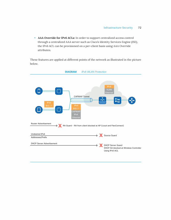
• AAA Override for IPv6 ACLs: In order to support centralized access controlthrough a centralized AAA server such as Cisco’s Identity Services Engine (ISE),the IPv6 ACL can be provisioned on a per-client basis using AAA Overrideattributes.
These features are applied at different points of the network as illustrated in the picturebelow.
DIAGRAM IPv6 WLAN Protection
Infrastructure Security 72

Securing the Air
Protecting network access to the Wi-Fi shared medium presents a unique set ofchallenges. Securing the air means protecting the wireless devices that access thisnetwork. Cisco provides unique capabilities to detect and mitigate possible threats thataffect Wi-Fi communications. Cisco approaches securing the air by leveraging multiplecomponents at different layers, as illustrated in the figure below.
DIAGRAM Wireless Threat Detection and Classication
Detecting Security threats with Cisco CleanAir
In a wireless network, air is a shared medium using unlicensed spectrum and issusceptible to multiple challenges. One of the challenges is caused by Wi-Fi and non-Wi-Fi interfering devices which can negatively impact client performance and networksecurity. Devices such as wireless video cameras or analog cordless phones may
Infrastructure Security 73

accidentally cause an impact to the network. With Cisco CleanAir, the wireless networkis protected by detecting, identifying and locating these interference sources and theirassociated impacts.
Cisco CleanAir is a custom silicon-based integrated solution with patented chipset andsoftware that has been designed to analyze and classify all RF activities. CleanAirtechnology operates 24x7x365 to monitor the entire Wi-Fi spectrum for interferenceand notifies IT admin about the primary sources of interference as soon as they appear.
In addition to detection, Cisco CleanAir offers self-healing capabilities to WirelessNetworks. These capabilities include persistent device avoidance and event-driven RRM(ED-RRM):
• Persistent device avoidance recognizes that certain devices tend to be static inlocation and frequency; for example, microwave ovens and wireless videocameras. For this reason, even when these devices are not currently beingdetected on a specific channel at a specific location, it is known that they arelikely to return at locations in which they have been detected previously. Thesystem tracks these devices, and when channel selection is performed, avoidsaffected channels at these locations.
• Event-driven RRM recognizes that some interference events are severe andcatastrophic in nature. Such dramatic drop in air quality causes the system toimmediately change the channel for the affected access point without waiting forthe next global channel evaluation cycle.
Cisco CleanAir includes a suite of non-Wi-Fi classifiers that can uniquely identifyvarious types of interferer devices that affect spectrum quality. CleanAir can alsophysically locate the source of interference and avoid duplicate detection. CMX orCisco Prime Infrastructure integrated with the Mobility Services Engine (MSE), providevisualization tools to display access points and clients along with the interferer devicesand their zone of impact on a map.
Adaptive WIPS (aWIPS)
Cisco aWIPS provides a reliable wireless security solution which embeds wireless threatdetection and mitigation of over-the-air attacks. aWIPS consists of a number of
Infrastructure Security 74
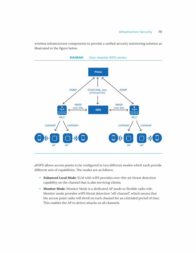
wireless infrastructure components to provide a unified security monitoring solution asillustrated in the figure below.
DIAGRAM Cisco Adaptive WIPS solution
aWIPS allows access points to be configured in two different modes which each providedifferent sets of capabilities. The modes are as follows:
• Enhanced Local Mode: ELM with wIPS provides over-the-air threat detectioncapability on the channel that is also servicing clients.
• Monitor Mode: Monitor Mode is a dedicated AP mode or flexible radio role.Monitor mode provides wIPS threat detection “off-channel”, which means thatthe access point radio will dwell on each channel for an extended period of time.This enables the AP to detect attacks on all channels.
Infrastructure Security 75

Rogue Device Management
Devices that share the common spectrum but which are not part of the local networkare considered rogue devices. Rogue access points can act maliciously by hijackinglegitimate clients and performing man-in-the-middle attacks. They can also capturesensitive information such as usernames and passwords, prevent legitimate clientsfrom sending or receiving traffic, and cause a denial of service.
Rogue detection is enabled by default on the access points connected to the WLANcontroller. Cisco wireless networks provide a complete solution for detecting andmitigating rogue APs which includes Air/RF detection and classification, rogue APlocation and rogue containment:
• Air/RF Detection and Classification: Cisco Aironet APs detect rogue APs as wellas ad-hoc clients and rogue clients (the users of rogue APs). This information issent to the Wireless LAN Controller for holistic analysis. The WLC can determineif a rogue AP is attached to the local network or if it is simply a neighboring AP.Rogue classification rules define sets of conditions that mark a rogue as eithermalicious or friendly.
• Rogue AP Location: CMX, or Cisco Prime Infrastructure integrated with theMobility Services Engine (MSE) provides visualization tools to display rogueaccess points and rogue client locations, as depicted below.
Infrastructure Security 76

DIAGRAM Locating Wireless Threat on Cisco Prime Infrastructure
• Rogue containment: Once a rogue AP or client is detected, it can be manuallycontained. This should be done only after steps have been taken to ensure thatthe rogue AP or client is truly malicious, as such containment action may havelegal implications.
Infrastructure Security 77

Policy

Introduction
As more and more users, devices, and applications come onto the network, the growingcomplexity of ensuring that they all receive the appropriate level of security andservices becomes a challenge. Cisco provides a rich set of tools which enables theadmin to create granular policies that can be applied to a user, group of users, and/or adevice type. Cisco wireless policy has two critical components:
• Security: The security policy for wireless creates rules that control access todifferent parts of the network, based on the user-role or device type.
• Quality of Service(QoS): QoS helps regulate the flow of traffic on a network andensures that high priority applications flow seamlessly across a network andreceive a differentiated level of service.
DIAGRAM Network Policy Framework
Policy 79

Security Policy
Every organization needs a network security policy as it represents the cornerstone ofthe IT security program. A network security policy defines how the different users anddevices (BYOD, IoT) get access to the corporate IT assets.
Cisco Enterprise Wireless leverages unique security capabilities around profiling andIdentity-Based Networking Services (IBNS) available on the WLC and access point.These provide IT with a comprehensive set of rules to define the right security policy tomeet the business needs.
Basics of Security
Role-Based Policy
Cisco offers the ability to create a security policy on a per user-role and/or per devicebasis. Upon authentication, the RADIUS server establishes the identity and returns theconfigured policy to the wireless LAN controller for enforcement. The policy can definenetwork segmentation (VLAN, ACL etc), and can be combined with Quality of Service(QoS).
Device Profiling
The user is identified at authentication time, however, identifying the device being usedrequires a little more investigation. For this, Cisco uses Device Profiling. WLC and/orRADIUS (e.g. ISE) identifies devices based on detected protocols such as HTTP andDHCP, and traffic characteristics. Based on this detection, an administrator can define apolicy that can be applied to a specific device type rather than just a user.
For instance, if an employee’s device type does not meet the minimum OS securityrequirements for the enterprise, it can be denied access to specific resources orassigned to a quarantined VLAN until the concern is remediated. Another example canbe Bring Your Own Device (BYOD), where device profiling is used to ease theonboarding process for iOS, Android, MacOS and/or Windows-based devices.
Policy 80

Access Control List (ACL)
ACLs allow a network administrator to create rules to restrict access to the networkresources. These rules can be applied to all clients in a WLAN, or returned dynamicallyfor a specific client or group upon authentication with a RADIUS server. Thiscombination offers a wide flexibility to ensure that each user accesses the rightresources, irrespective of the access method used. Cisco Aironet solution supportsMAC Layer ACLs, IP(v4 and v6), as well as DNS-based ACLs.
Securing mDNS Bonjour and Chromecast Access
As more and more personal devices become working tools, protocols designed forhome or small networks come to the enterprise. Bonjour and Chromecast are examplesof such protocols. Derived from the mDNS family of protocols, they use multicast todistribute information between peers. However, the form of multicast they use cannotbe routed across subnets, making distribution challenging in enterprise environments.
Cisco Wireless Solution offers mDNS proxy functions, with enhancements for Bonjourand Chromecast. Acting as a gateway, wireless LAN controllers allow the discovery ofwired and wireless mDNS devices and services across Layer 2 and Layer 3 subnets. WithBonjour profiles and policies, available in the WLAN controller, the administrator candecide which device will be allowed to discover and use which mDNS service.
Enterprise Network Policies with 802.1X
The Identity Based Networking Services (IBNS) framework provides a way todynamically apply rules to users and devices upon authentication to the network.Endpoints can be classified based on the role of the user as well as the device used toconnect to the network. In the use case illustrated in the figure below, employees andcontractors are connecting to the enterprise network using 802.1X. Based on useridentity and/or the type of device they are using, a specific VLAN is assigned to eachclient. This allocation is an effective segmentation method. With the RADIUS serverreturning parameters such as user-role, the employees can further be categorized intodifferent functions within the organization, for example, Sales and Marketing.
Policy 81

DIAGRAM Role-based Policy on Cisco Wi-Fi
Each group can then receive differentiated access to the network resources. Forexample, Sales and Marketing are allowed access to Internet domains, applications suchas Jabber and Webex and printers within the office; contractors are only able to accessa limited set of websites, applications, and wireless printers. In addition, these policiescan also be made time-sensitive, meaning that rules can be applied to specific days andtimes of the day in a week.
Similarly, policies also help differentiate the level of QoS and bandwidth that each userreceives, and this can help to allocate bandwidth for employees using business-criticalapplications and limit bandwidth for users accessing non-mission critical applications.
Policy 82

Location-based Access Control
Most vendors can provide basic access control (for example, with 802.1Xauthentication); Cisco uniquely adds location context when implementing accesscontrols. With location-based contexts, administrators can grant access to users basedon their specific physical location. Traditionally, the definition of “location” on thenetwork is static, associated to the specific access point that a user connects to fornetwork access. With the Cisco solution, the administrator can define specific areas ona map and provide differentiated access.
As an example, in a manufacturing area, some resources may only be accessed fromphysically protected areas. Similarly, in hospitality, accounting records may not beaccessible from the public areas.
IoT Device Segmentation with Identity PSK (iPSK)
The advent of IoT devices in an enterprise increases the security threat surfaceexponentially and also exposes the network to unsophisticated devices that do notalways comply with the latest wireless security standards. Traditionally, IoT devices areconnected to WLANs that use Pre-Shared Keys (PSK). The challenge is that all clientsjoining the WLAN share the same key, leading to security issues if keys are shared withunauthorized users. If the key is compromised on one client, the key for every clientassociated with that network needs to be changed. Most of the IoT devices do notsupport 802.1X authentication mechanism, which implies that they cannot besegmented based on AAA-returned attributes.
iPSK provides the ability to create a unique PSK for each device connecting to an SSID,thus simplifying IoT device onboarding while ensuring the security is not compromised.iPSK relies on the RADIUS server to generate a unique PSK per device or group ofdevices. Each IoT device can then be assigned a policy. This mapping also helps torevoke access if a device goes missing or is compromised. The following pictureillustrates these principles.
Policy 83

DIAGRAM iPSK Implementation
As an example, IoT devices, such as sensors, intelligent lights, and other smart devicesusing Identity PSK, can be assigned parameters such as VLAN, Cisco TrustSec ScalableGroup Tags (SGTs) or ACLs. With this mechanism, access control can be applied toprovide differentiated authorization and service to different IoT devices.
Policy 84

DIAGRAM IoT Segmentation rules by device type
Guest Access (Central and Local Web Authentication)
Enabling secure guest access is one of the most common policy use-cases in enterprisewireless. Cisco provides multiple options to setup Guest Wi-Fi and limit guest traffic toa secured segment of the network. Cisco wireless provides two ways to authenticateguest users onto the network:
• Local Web Authentication (LWA) – In LWA, WLC will redirect to an internal orexternal server where the guest user can perform self-registration andsubsequently authenticate. The WLC authenticates the user against a RADIUSserver.
• Central Web Authentication (CWA) – In CWA, web authentication is done at aRADIUS server. This is very useful in large enterprises with multiple wireless LANcontrollers because it provides efficiencies of scale by consolidating webauthentication to a central location, and potentially provide additional profilingand authorization conditions.
Policy 85

Umbrella WLAN
Umbrella-enabled WLAN enforces security at the Domain Name System (DNS) layer,which means that client traffic to malicious domains and unwanted web categories canbe blocked before a connection is made. Umbrella, dynamically learning from 100+billion requests per day, uncovers and predicts threats. Cisco WLANs can takeadvantage of this additional protection layer by relaying WLAN user DNS requests toUmbrella and automatically apply the returned protection policies, as illustrated in thefigure below. This integration is seamless (one click). Being cloud-based, Umbrella doesnot require any on-premise dedicated filtering device, reducing the cost of operationand implementation.
DIAGRAM Umbrella Secured WLAN
Policy 86

Cisco TrustSec
Simplifying traditional VLAN-based designs and reducing the operational effort ofsecurity maintenance becomes more challenging as the network scales and grows.
TrustSec helps deploy a scalable and simplified solution for end-to-end segmentation.Instead of defining and applying policies based on network constructs (IP addresses,subnets, VLANs, etc.), Cisco TrustSec uses a security group (SG) abstraction toaggregate users and devices, making the policy definition simpler.
Cisco TrustSec uses the device identity and user credentials to label packets withscalable group tags (SGTs) as they enter the network. The label is used by the networkelements to apply and enforce security and other policy criteria along the data pathusing SG-ACLs. Cisco ISE is the single point of policy definition where SGTs and SG-ACLs are created and mapped with users or groups.
Policy 87

QoS Policy
Quality of Service (QoS) for Wireless
In the 2000s, wireless networks were designed around use cases. One SSID would bedesigned for voice (and only voice traffic would be expected for that SSID); anotherSSID would be designed for data, and so on. Many wireless infrastructure vendors stillapply this model. However, smartphones changed this logic. They are hybrid devicesand there is no easy way to determine what application they will use: voice, standarddata, background applications, and others.
Cisco wireless networks have evolved to adapt to these new requirements. Today, anetwork administrator should limit the number of SSIDs to a minimum, so as to avoidwasting air-time with multiple beacons and other management frames. Within thisreduced number of SSIDs, devices may connect with various QoS requirements. Somedevices may need high QoS marking for their applications, some others will not needany differentiated QoS at all.
Wireless QoS Basics
QoS is an end-to-end problem and should be addressed on each segment of thenetwork. Packets can be marked with a value that expresses the carried applicationsensitivity to loss, delay, and jitter. Layer 3 marking, applied on the IP header andcommonly using the Directed Service Code Point (DSCP) marking convention,expresses the end-to-end QoS intent of the packet. Most well-known application typesbear markings that have been agreed upon by the industry. For example, real-time voiceis usually marked with the DSCP code 46 or EF, real-time video with 34 or AF 41, andbackground traffic with 10 or AF 11. Then, on each medium (Ethernet, 802.11 etc.), atranslation mechanism expresses the QoS marking in the L2 header, with values thatfurther account for the particular medium constraints. On the 802.11 medium, QoS isexpressed with 8 User Priorities (UP), grouped into 4 Access Categories (AC). A highermarking value reflects a higher priority.
Policy 88

WMM (Wi-Fi Multimedia)
On a Cisco wireless LAN controller, policies are configured with the notion of QoSprofile. The QoS profile acts as a ceiling that reflects the highest QoS marking allowedfor the SSID to which the profile is applied. For example, a Platinum QoS profile willallow up to DSCP 46, matching all enterprise SSID traffic requirements, from best effortto background, video, and voice. A Gold QoS profile will allow up to AF 41 (typically usedfor interactive video). Any incoming traffic with higher marking will be marked down tothe ceiling value, AF 41 as illustrated in the figure below. Any traffic with a lower QoSvalue will be sent unchanged.
DIAGRAM E�ect of the Gold QoS prole ceiling
The QoS profile allows for marking traffic that does not already come with a QoSmarking, including multicast traffic. This way, an enterprise general SSID can decidethat unmarked traffic should be left unmarked (DSCP CS0), while a specialized SSID(voice for example) can decide that unmarked traffic is likely to be voice, and shouldalso be marked DSCP 46. This flexibility of a ceiling QoS value, combined with defaultvalues, allows the administrator to set general contextual rules for traffic QoSmanagement for each SSID.
With AAA override, covered in the Security chapter, specific rules can also be appliedon a per client or per group basis. This way, the SSID can be configured with general
Policy 89

rules, but specific groups of clients on that SSID can receive different rules, adapted tothe specific device requirements.
Call Admission Control (CAC)
In some networks, voice applications are critical to the business. For example, hospitalsoften use Wi-Fi voice handsets in an environment where multiple other devices, butalso patients and guests, use the same Wi-Fi network. In such a context, it is necessaryto make sure that only voice calls that are business-critical receive the highest priority.Cisco WLANs offer such a feature with Wireless Call Admission Control (CAC), alsocalled Access Control Mandatory (ACM). When this feature is enabled on a radio band, aspecial 802.11 marking is sent in the AP frames, that indicates to client stations that theycan use the voice queue (User Priority, UP 6), only if they first ask for permission. Thisrequest is made in the form of a special frame (ADDTS, Add Traffic Stream), thatcontains a description (TSPEC, traffic specification) of the voice traffic to be sent. Uponreceiving such a request, the AP examines the available resources and determines if thecell has enough additional space for this call. If the cell has space, the call is admittedand benefits from the highest voice priority. But what happens if there is no space?Admitting the call would result in poor quality of experience, not only for the additionalcall but also for all the other already admitted calls. For this reason, the AP can refusethe call, pushing the client to either use a lower priority or roam to anotherneighboring cell that still has capacity left. (In a Cisco network, all APs announce theavailable space in beacons and probe responses).
This mechanism ensures that an optimal quality of experience is offered to all admittedcalls, while also providing visibility into the cell capability for all voice devices so thatthey can associate to the AP that provides the best capacity. An additional benefit isthat devices that would attempt to bypass the rules, sending UP6 traffic without askingfor permission first, will get returned only best effort traffic.
DSCP Trust
When QoS for wireless was designed in the early 2000s, the industry perspective wassolely focused on Layer 2 QoS, comparing Wi-Fi to Ethernet. Many wirelessinfrastructure vendors are still stuck in this logic. However, Cisco is uniquely positionedas a global networking company and considers QoS as an end-to-end concern. As such,it does not make sense to look at Ethernet QoS (which is only relevant to express QoS
Policy 90

valid on an Ethernet medium, with its specific constraints), and use that Ethernet QoSto decide of the 802.11 UP value, and vice versa for the upstream traffic. Layer 2 QoS isonly relevant to a specific medium. By contrast, the DSCP value is carried across alltraversed mediums and expresses the global QoS intent of a packet, irrespective of thelocal medium. When converting QoS from one medium to another, the global intentshould be used, not the local intent of the previous medium.
To allow this end-to-end logic to be fully used, Cisco APs can be configured to use theupstream DSCP value present in wireless client packets (instead of the 802.11 UP value),to decide of the Ethernet QoS value. This process is called DSCP-trust. Similarly,downstream, DSCP is used to determine the 802.11 access category (and associated UP)value. This new logic was not only introduced by Cisco but was also pushed to the IETF(RFC 8325) and validated by the rest of the networking industry. Implementing suchlogic is a dramatic evolution of WLAN QoS policies, as it optimizes the globally-differentiated treatment of packets across the network. Administrators can evenconfigure customized maps, to decide which DSCP range should translate to whichparticular UP and vice versa.
Rate Limiting
Applying the appropriate marking is not the only way of controlling the quality ofexperience. For example, suppose that a guest, or a contractor, uses the network. Inmost cases, the administrator would want to provide differentiated quality of service toa voice application, but would not want the guest or the contractor to consume anunrealistically large amount of bandwidth. However, how would the invited user knowwhat bandwidth is reasonable to consume? In Cisco controllers, each user can beassigned to a group, called a role. Then, bandwidth limitations can be associated withthat role. The limitation can be applied for upstream and downstream traffic, and adifferent bandwidth can be set for UDP and TCP traffic. This combination provides alarge flexibility for the administrator to fulfil the invited user requirements while posingboundaries on the bandwidth consumed.
This solution has flexibility built-in, to match all network deployment types. Forexample, roles can be created directly on the WLAN controller, for smaller networks. Inlarger entities, where an AAA server is installed, these bandwidth rules can be returnedas an authorization profile at the end of the authentication process. Rules can also beset directly on a per SSID basis, matching the requirements of specialized networks (e.g.
Policy 91

contractor or guest SSIDs). Similarly, bandwidth rules can be applied to QoS profiles. Inturn, a QoS profile can be applied to one or more SSIDs, or be applied to a group ofusers, irrespective of the SSIDs they associate to.
Airtime Fairness (ATF)
There are cases where the administrator will want to strictly control the bandwidthallocated to specific users. A typical case is an enterprise environment with contractors,or a hotel with specific guest bandwidth contracts. However, there also may be caseswhere assigning a strict bandwidth limitation may not be the best solution. Somenetwork administrator may think that bandwidth should only be limited if it becomes aconstrained resource. A common example of such environment is a shopping mall withguest and staff SSIDs. Staff needs higher priority access to complete their mission, butguests might not be restricted if bandwidth is available. Similarly, a hotspot, or auniversity, might decide that bandwidth should only be restricted when it is needed forbusiness or educational applications. As long as the network provides enough space, alltraffic might be admitted. It is only when congestion occurs that stricter control may beneeded. To answer this dual need for control and flexibility, Cisco created Air TimeFairness (ATF).
Airtime and bandwidth are different concepts. A strict bandwidth definition could bestated as, for example, “6 Mbps”. Such number provides a deterministic experience forthe user but is not reflective of the airtime. Close to an 802.11ac access point, a muchhigher bandwidth is available. Far from an access point, such bandwidth might generatecongestion issues for all SSIDs sharing the same radio. By contrast, as its nameindicates, ATF functions at the level of the airtime, not at the strict bandwidth level, andis therefore built at the radio level. This way, a percentage of the airtime can beallocated to each SSID as illustrated in the figure below.
Policy 92

DIAGRAM Air Time Fairness Principles
Airtime Fairness provides a unique granular control because it functions at the RF leveland can allocate flexible airtime based on the available resources. However, ATF canalso be combined with strict bandwidth policies, giving the administrator a large set ofpossibilities, with strict bandwidth control on some SSIDs, some QoS profiles for someusers, while also ensuring a fair airtime split between SSIDs of various business-relevance.
Wireless QoS Use Cases
Videostream
The network must be able to deliver real-time streaming content, for example, video orvoice, in a reliable manner. Imagine a company quarterly meeting streamed across the
Policy 93

enterprise using multicast with a substantial portion of the end clients connectedwirelessly. Wireless clients are susceptible to issues such as interference, poor roaming(stickiness), high channel utilization and collisions. In such an environment, distributingframes over Wi-Fi through multicast may not be the best method. Multicast frames aretransmitted unreliably, without acknowledgements. As no client acknowledges theframes, the AP has no way to detect if a client failed to receive its copy. Failures arethen left uncorrected. Additionally, wireless multicast frames are transmitted at lowspeeds (one of the basic rates), slower than unicast frames. Cisco Wireless can leverageVideostream to address these challenges. Videostream, at its core, filters whichmulticast flows are allowed, then converts the allowed multicast streams at the AP intounicast frames over the air as illustrated in the figure below. This allows the originalmulticast data to take advantage of 802.11 unicast characteristics such as highertransmission data rates (11n, 11ac) aiding in efficient bandwidth utilization. It also allowsthe stream to become more reliable by taking advantage of 802.11 individualacknowledgement and retries. The wired network continues to preserve wiredbandwidth as the traffic remains multicast on the wire up until it reaches the AP.Videostream takes things a step further by giving the administrator control over streamadmission, prioritization, and radio reservation control.
Policy 94

DIAGRAM Videostream Multicast to unicast conversion
Application Visibility and Control (AVC)
Wireless has evolved to become the primary access medium in the enterprise, but whattraffic is traversing the wireless network? Is that traffic adversely impacting business-critical applications? Does the wireless network detect whether business non-relevantapplications are causing congestion issues? Does the current wireless network designhave enough bandwidth to handle ever-growing application requirements?
Policy 95

Application visibility and control (AVC) provides application-aware visibility into thetraffic traversing the wireless network. AVC relies on Deep Packet Inspection (DPI)technology called Network Based Application Recognition version 2 (NBAR2) to identifyand classify applications. Applications are recognized by the port they use, but also bytheir traffic pattern. NBAR2 can recognize more than 1400 applications, even whentraffic is sent encrypted. Once the traffic is identified and classified, it is passed on toother mechanisms such as QoS and ACLs for potential action (e.g. drop, rate-limit, markQoS). AVC provides the network administrator with the ability to view applicationstatistics to aid in capacity planning, provide network application usage baselines, andfurther insight into who and what is consuming bandwidth. An example of suchvisualization capability is displayed in the figure below.
DIAGRAM Visualizing Tra�c with AVC on a WLAN Controller
Policy 96

Fastlane
End-to-end QoS presents a unique challenge on the client-to-AP segment of Wi-Finetworks. On Ethernet segments, each client connects directly to an individual switchport, and QoS can be applied right at the point of connection. But in Wi-Fi networks,several clients share the same radio link to an AP. In this space, the AP has no controlover the QoS marking that each client may decide to apply to each upstream packet.Prior to the Cisco-Apple partnership, the AP also did not have any way to inform theclient about the network QoS policy. This resulted in over-the-air upstream QoSpolicies that were not always correlated with the QoS policies configured on thenetwork.
Working together, Cisco and Apple designed Fastlane. When this functionality isenabled for a wireless network, the APs start advertising the capability in an 802.11information element. Best practice QoS is also configured automatically on thecontroller, which includes the creation of an AVC policy indicating the correct QoSmarking for most common business-critical applications. In parallel, a mobile devicemanager (MDM) can configure a profile on iOS or MacOS clients, that contains a list ofthese business-relevant applications. When the iOS or MacOS client detects a networkwhere Fastlane is enabled, the client also checks if it has a whitelist for that SSID. If awhitelist has been configured, the client then only applies QoS marking to theapplications in the whitelist. All the other applications are sent as best effort.
A great advantage of this feature is that it is network-specific, allowing administratorsto configure different policies for different networks. For example, the same iPad couldhave a set of policies in a classroom, and another set of policies in a dormitory. For thefirst time, QoS becomes truly end-to-end, starting from the wireless client.
AutoQoS
Deploying wireless network QoS has become increasingly complex as the technologyraces forward. Choosing the correct settings while adhering to best practices hasbecome challenging. The decision is made even more complex when the QoSconfiguration applied to the WLCs and the WLANs has to fit into a broader end-to-endQoS strategy, involving multiple types of platforms and configuration logics.
Policy 97

As QoS for Wi-Fi has evolved a lot over the last 15 years, only a subset of configurationsis considered to be best practice in today's enterprise networks. The three constructsare: applying a QoS ceiling that allows for voice traffic, trusting DSCP with an RFC-8325-compatible QoS map, and protecting voice queues with a reasonable reservedbandwidth. With Intent-based Networking, the administrator can use the DNA Centerpolicy component to generate marking rules for the applications in use on the network.Upon applying these policies to the WLC, an autoQoS macro function also configuresthe WLC automatically as per best QoS practices.
DIAGRAM QoS Policy Conguration on DNA Center
On the WLC, enabling Fastlane on an SSID also automatically configures the WLC forQoS best practices. Both enabling Fastlane and applying DNA Center QoS policies to theWLC enable QoS best practice configurations on the WLC. The major differencebetween these two modes is that DNA Center also allows for the creation of QoSmarking rules through an intuitive interface for common applications in use in theenterprise, while Fastlane also activates the Fastlane mode used by iOS and MacOSdevices. However, enabling Fastlane also creates a set of QoS marking rules for the most
Policy 98

common enterprise applications. This set of rules is not applied automatically, but isprepared and can be applied in a single click, thus saving the administrator time.
Policy 99

Analytics
Introduction
Network Analytics is about extracting data from the network and processing it totransform raw information into insights. These insights need to be communicatedefficiently to a management platform so they can be used to optimize workflows,improve business decisions and operations. Network Analytics is a key principle of theDNA architecture.
First of all, analytics requires data. The Cisco network provides an incredible amount ofinformation. The network connects everything (users, devices, applications, processes)and transports all the information that these assets produce. Cisco wireless networkand its components (WLC and APs) can capture relevant data, and transmit it efficientlyusing telemetry protocols.
Contextual information adds value to the data extracted from the network. Netflow, forexample, a technology used to provide information about application flows, offersextremely useful information about traffic traversing the network. Additional insightscan be gained by adding information about the context (e.g. user identity, security,location, etc.); correlating the user information with application information can greatlystreamline the troubleshooting process. Knowing the location of these devices opensup an array of possibilities for richer analytics and improved troubleshooting. Ciscocontinues to drive location-based features to fit the needs of a diverse customerfootprint by offering location options for associated and non-associated devices.
DNA Center is the platform that provides data collection, processing, and correlation.Within DNA Center, Assurance delivers advanced analytics for new levels of insight andvisibility, across the network and all the way down to the user and their device. Thisenables IT to dramatically reduce the amount of time and money spent troubleshooting.IT can also be more empowered in proactively identifying, diagnosing and evenpredicting issues across the network.
Another core component of Analytics is Cisco Connected Mobile Experience (CMX).CMX Analytics provides unprecedented visibility into client and customer movingpatterns that help drive business decisions in different verticals. Workspace analytic
Analytics 101

systems can integrate with CMX to manage building capacity, or a hospital can leverageCMX location data to track valuable assets for healthcare regulatory compliance.
DNA Center Assurance and CMX Analytics rely on Cisco unique innovations in bothhardware and software such as Flexible Radio Assignment, Hyperlocation, IntelligentCapture and device telemetry to help collect useful insights from the network.
Analytics 102

DNA Center - Wireless Assurance
Cisco DNA Center helps administrators gain insights from their network. The solutionproactively monitors the network, gathers and processes information from the devices,applications, and users. DNAC provides an easy to use visualization dashboard.
With a quick check of the network health dashboard, the administrator can see wherethere is a performance issue in the network and identify the most likely cause.Hierarchical sitemaps help correlate issues down to the specific site or networkelement. For wireless, the admin can get a snapshot of the system health and the dataplane connectivity.
Another key element of the Wireless Assurance solution is the Client 360 view and itsassociated dashboard displayed in the illustration below. If a user is reporting an issue,Client 360 provides visibility and quickly brings the necessary client information to thesurface for troubleshooting. The Client Health score gives a key indication of the clientwireless connection quality, while the time machine function allows IT admin to lookback in time at relevant KPIs at the time of the issue. Finally, path trace is a tool totroubleshoot connectivity and performance issues end-to-end.
Analytics 103
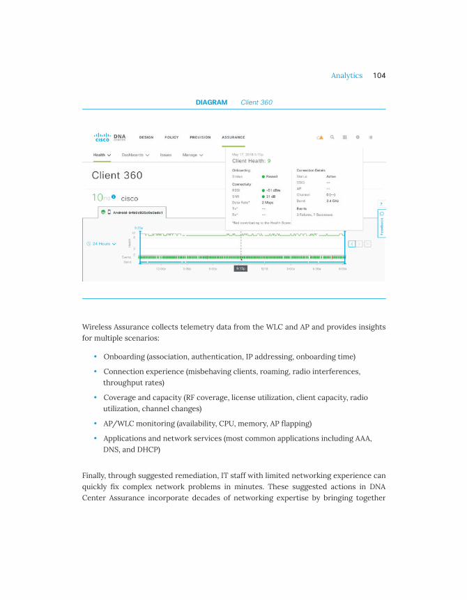
DIAGRAM Client 360
Wireless Assurance collects telemetry data from the WLC and AP and provides insightsfor multiple scenarios:
• Onboarding (association, authentication, IP addressing, onboarding time)
• Connection experience (misbehaving clients, roaming, radio interferences,throughput rates)
• Coverage and capacity (RF coverage, license utilization, client capacity, radioutilization, channel changes)
• AP/WLC monitoring (availability, CPU, memory, AP flapping)
• Applications and network services (most common applications including AAA,DNS, and DHCP)
Finally, through suggested remediation, IT staff with limited networking experience canquickly fix complex network problems in minutes. These suggested actions in DNACenter Assurance incorporate decades of networking expertise by bringing together
Analytics 104

experience from Cisco TAC, Cisco escalation, and feedback from real-world customernetwork environments to determine the best steps for each issue.
Streaming telemetry
Collecting data for analytics and troubleshooting has always been an important aspectof monitoring the health of a network. Existing mechanisms like SNMP, CLI, and Syslog,although useful, also have limitations that restrict automation and scale. SNMP, forexample, is based on a pull model: the server opens a connection and requests a set ofvalues, the network device processes the request and returns the data in the formatrequired by the server. If there are multiple polling servers, multiple connections needto be opened and processed in parallel. This process is not optimized, therefore SNMPscale is a known issue. Also, the network sends data only when requested, which meansthat an event can occur and related data can be missed because it is not collected in therequired interval.
To overcome these and other limitations, Cisco is providing a model-driven streamingtelemetry approach across switching, routing, and wireless. Streaming telemetryleverages a push model which provides near-real-time access to monitored data. Thedevice sends the data to a receiver at regular intervals or upon a triggering event. Thismechanism also optimizes the transmission to multiple receivers; the device simplyneeds to duplicate the data locally and send it to multiple collectors.
Streaming telemetry provides the quickest and most efficient way to get access tonetwork state indicators, network statistics, and critical client information. By modelingdata with YANG (Yet Another Next Generation), telemetry is transmitted in a structuredand easy-to-consume format to remote management stations.
Streaming telemetry is key for wireless. The Wireless LAN Controller sends relevantclient and network data to DNA Center, where it is processed and displayed to helpnetwork monitoring and troubleshooting. For example, a user is reporting aconnectivity issue, and the telemetry data shows that the client is failing to completeauthentication during onboarding. However, the AAA server is responding, so the issueis not on the server side. With the data provided to Assurance, the administrator canquickly determine that the wireless client itself is not responding due to an RF issue.Wireless telemetry actually shows a dual-band capable client consistently connecting
Analytics 105

to 2.4 GHz instead of 5 GHz. From the client location, a better 5 GHz signal is notavailable, which immediately provides visibility into the source of the issue.
Active Sensor Testing
When Wi-Fi is the primary network access medium, it becomes mission-critical andrequires a proactive approach to performance monitoring. Cisco Active Sensorsimulates real-world Wi-Fi experiences by automating scheduled or on-demand testingof client connectivity, speed, and coverage. Active Sensor functionality is supported onthe following modes:
Dedicated Active Sensor: dedicated active sensor 1800s is a standalonecompact wireless device that can provide high fidelity insight at desktop level,where the majority of mobile devices are located
AP as a Active Sensor: the AP can act as a client to perform RF and service teststhrough other APs.
Aironet Active Sensors collect data and proactively measure the health of the Wi-Finetwork. The test suites, managed by Cisco DNA Center, provide the ability to performtests of critical network functions such as:
• Client onboarding experience: DNA Center can be used to test networkonboarding services such as DHCP, DNS, Authentication services (RADIUS) as wellas testing the basic 802.11 association requests.
• Client connectivity experience: Test suite can be used to create specific testssuch as Ping, FTP transfer, HTTP and HTTPS connectivity to ensure clients cansuccessfully connect and send data through the wireless network.
Intelligent Capture
Packet Captures provide an incredibly rich data set that helps a network administratorto troubleshoot and diagnose Wi-Fi and client issues. However, most capture toolsmandate an on-site technician to manually capture packets.
1
2
Analytics 106
Intelligent Capture is a new innovative feature powered by Cisco Aironet APs working inconjunction with DNA Center Assurance. This automated packet capture can bescheduled, triggered by error events, or started on-demand. The capture can also berun across multiple APs. As a client roams across multiple APs, a consolidated capture isgenerated from the viewpoint of each AP that the client connects to. DNA CenterAssurance is then able to provide automated initial analysis and visualization of thecaptured data. Administrators also have the ability to receive the full capture data forout-of-band analysis.
iOS Wi-Fi Analytics
iOS Wi-Fi Analytics bring the client view into the wireless network analytics. This is oneof the results of the collaboration between Apple and Cisco. The client reports its viewof the network at association time, listing detected APs and their signal, along with theclient hardware and software details. Why is the client view so important? From an RFperspective, access points already capture and export a lot of data for processing. ButAPs are usually located near the ceiling and have a view of the RF different that of theusers' devices at floor level. Even if an AP can be turned into a client sensor, it still has aprivileged line-of-sight connection to the other APs at ceiling level. Additionally, theAPs usually have higher gain and higher sensitive antennas compared to the ones foundin clients.
Another aspect of client-side analytics is the "disconnect reason" code. When a userreports a connectivity problem, it's not necessarily a network issue. It could be a clientdisconnecting for some power-related or software-related reason. With iOS Wi-FiAnalytics, the iOS device communicates the reason for a disconnection directly to theinfrastructure, saving a lot of time in troubleshooting.
DNA Center Assurance collects all these client insights and displays them in the client360 view as illustrated in the figure below.
Analytics 107

DIAGRAM iOS Wi-Fi Analytics with Client neighbor AP data
Analytics 108

Connected Mobile Experiences (CMX)
CMX is a core component of Location Analytics. CMX Location Analytics provide deepvisibility into client location and moving patterns which can help enterprises indifferent verticals drive better business decisions. For example, workspace utilizationintegrated with CMX can provide analytics for workplace optimization. An exampleview is provided in the picture below. Similarly, a hospital can leverage CMX locationdata to track and visualize movements. Alternately, the data can be sent into an assetmanagement solution (e.g. Cisco Operational Insight) to track assets and create rulesbased on location and environmental state of the assets so as to support businessworkflows and trigger actions.
DIAGRAM CMX Analytics View
Analytics 109

Location
Presence and Basic Wi-Fi Location
Building a house requires the right set of tools. In the same way, building a location-aware network requires the right tools for detecting associated and non-associateddevices. Business requirements might dictate the need to know whether a device issimply in the store, in the vicinity or in a particular zone.
Presence
Cisco CMX Presence provides "cell of origin" level (who hears the device the loudest)location information with approximately 60ft/20m accuracy. This level of accuracyprovides the business with the knowledge that a device is somewhere on the premisesor in the nearby vicinity. In the illustration below, Presence detects that the client issomewhere in the gray circle, representing the AP cell. Presence location can beachieved with a single AP and without the need for location maps, making this thesimplest form of location to deploy. There is no need for a device to be associated withthe Wi-Fi network as Presence relies on the Received Signal Strength Indication (RSSI)collected from the probe requests from the clients. While simple to deploy, Presencecan provide powerful location analytics data such as repeat visitors, passerbyinformation, and dwell (length of stay) times. Presence, however, does not providelocation directionality and the level of accuracy which is possible with the otherlocation techniques discussed in latter part of this section.
Analytics 110

DIAGRAM Presence Location "cell of origin"
Basic Wi-Fi Location
Basic Wi-Fi location provides additional location fidelity by using trilateration. In orderfor trilateration to work, the design requires at least 3 APs but 4 or more APs arepreferred for better location accuracy. Basic Wi-Fi location builds on Presence byadding directionality to the computed location. The more APs hear the device, the moresamples are collected and, accordingly, the expected accuracy increases. In theillustration below, the client signal collected by each AP leads to a distance anddirectional value for each AP. The combination of the four values leads to theconclusion that the device must be located at the intersection displayed. Similar toPresence, basic Wi-Fi location uses the RSSI from collected probe requests. Basic Wi-Filocation accuracy is approximately 20-30ft/7-10m. This feature requires maps and APsto be placed accurately on these maps. Basic Wi-Fi location will narrow the locationanalytics data down to smaller zones as well as allow for path analysis and zone-to-zone analytics.
Analytics 111

DIAGRAM Device trilateration
Enhanced Location
Fastlocate provides enhanced location accuracy by focusing on Data RSSI packets ofassociated clients. Focusing on Data RSSI provides location systems with more data,improving location accuracy to 15-20ft/5-7m. As is the case with Basic WiFi location,Fastlocate uses trilateration and also requires AP placement on maps. The additionaldata collected uses the WLC Fastpath, which allows for quicker packet processing and
Analytics 112

faster location resolution. Enhanced location accuracy allows for the creation of smallersub-zones, resulting in improved granularity in analytics.
Hyperlocation
When the highest level of Wi-Fi location accuracy is needed, Cisco brings the mostadvanced tool. Business requirements may drive extremely accurate location fidelitydown to a micro-zone within a sub-zone, for example, a specific aisle location within astore.
Cisco Hyperlocation is the only Wi-Fi based Angle-of-Arrival (AoA) solution on themarket, and can provide location accuracy within 3-10ft/1-3m. The solution is poweredby purpose-built, industry-leading antenna technology. Hyperlocation uses its 360-degree antenna array system to locate the device by determining the AoA of the clientsignal. Multiple APs work together in Hyperlocation Groups and send their detailed AoAdata to CMX to be combined into highly accurate location results. Similar to Fastlocate,Hyperlocation leverages Data RSSI packets, WLC Fastpath and provides the highestlocation fidelity resulting in very granular analytics insights. With Hyperlocation, theadmin can pinpoint not only the aisle but where in the aisle the target is located, asillustrated in the figure below.
Analytics 113

DIAGRAM Hyperlocation
Operational Insights
Integrated with Cisco Aironet wireless portfolio, Operational Insights is a cloud solutionproviding a comprehensive resource for monitoring, managing, and optimizingenterprise assets, Internet of Things (IoT) sensors, alert systems, and operationalworkflows. Using a technology-agnostic approach, the solution can use a wide range oftags and sensors, including Wi-Fi, Bluetooth Low Energy (BLE), RFID, andenvironmental sensors, to continually integrate, monitor, and manage operationsworkflow. Through a cloud-based interface, administrators can define the profile,category, and ownership of each of the assets, establish business rules to defineworkflows, and the expected operating range of their assets and sensors.
Analytics 114

Operational Insights then continually monitors data from the sensors attached toassets, including telemetry data such as temperature and humidity. When any measuredeviates from the norm established by workflows, policies, and business rules, thesolution immediately takes action. It can send an alert and trigger an automated actionthat is predefined by the business workflows and rules. The solution provides anintuitive dashboard as illustrated in the picture below.
For example, in healthcare, there are lifesaving medications that are stored inrefrigerators. Using temperature/humidity sensors, Cisco Operational Insights cancheck the environment for changes. In meeting compliance or audit requirements,Operational Insights can provide a historical report of temperature and/or humidity,along with the location for every critical asset.
DIAGRAM Operation Insights Dashboard
Analytics 115

What's next?

Introduction
Over the last few years, Wi-Fi has become the primary mode for network access. This isespecially true in the consumer market where the rapid adoption of Smart Hometechnology, streaming media and IoT devices have increased the number of devices inthe home. It is very common to buy a device that is intended to connect to the network,yet which does not have any means to connect other than a Wi-Fi interface. In theenterprise, these devices thrive, and the need for flexible workspace and ubiquitousmobility has driven the massive adoption of Wi-Fi. The exponential growth of the BringYour Own Device (BYOD) and IoT markets have added the requirement for high density,efficiency, and security.
In less than 20 years of existence, 802.11 has become a 4000-page standard with 40different amendments and enhancements. Always in search for solutions to morechallenging problems, Wi-Fi is constantly evolving, adding new functions, supportingnew use cases, and bringing additional performance to support more users, moredevices, more applications, and greater demands on the network resources. With morethan 1000additional patents every year and hundreds of new features implemented inits wireless solutions, Cisco is following this fast pace with ease.
There are several innovations and trends that will affect the future of Wi-Fi. Withimproved efficiency in the use of spectrum, 802.11ax will accommodate the proliferationof IoT devices, another large trend. On the security front, the replacement of WPA2with a new version, WPA3, is likely to be a front-runner for a long time, as new storiesof attacks on weak and older implementations keep appearing. With a large change instructure and logic, 5G is also likely to affect the way networks are run. For each ofthese, Cisco is actively working on new products and features that will help bring theseinnovations to Cisco customers.
What's next? 117

WPA3
Security is a concern for any network, but it's an even more critical component for Wi-Fi as the transport media is shared and frames can be detected beyond the directclient-to-AP link. WPA2, the current standard for Wi-Fi security, was created to fill insome of the gaps within the original WPA implementation, providing both anauthentication and an encryption framework. Multiple enhancements have been madeto WPA2 over the years, such as Protected Management Frames, Fast BSS Transition,and utilization of stronger cryptographic algorithms under the covers. However, the“KRACK attack” blog, published in October 2017, put a spotlight on Wi-Fi security thathighlighted a need for the industry to move to a new generation of authentication andencryption mechanisms. This brought forward a need for enhancements to the existingWPA2 features, creating the next iteration, named WPA3. WPA3 covers four differentfeatures, with four different contexts: WPA3-Personal, WPA3-Enterprise, OpenNetworks, and IoT secure onboarding.
WPA3-Personal
WPA-Personal uses passwords, called pre-shared keys (PSK). Attackers can eavesdropon a WPA2 valid initial “handshake”, and attempt to use brute force to deduce the PSK.With the PSK, the attacker can connect to the network, but also decrypt passedcaptured traffic. The likelihood of succeeding in such an attack depends on thepassword complexity: dictionary words or other simple passwords are vulnerable.
WPA3-Personal utilizes Simultaneous Authentication of Equals (SAE), defined in theIEEE 802.11-2016 Standard. With SAE, the experience for the user is unchanged (create apassword and use it for WPA3 personal). However, WPA3 adds a step to the “handshake”that makes brute force attacks ineffective. The passphrase is never exposed, making itimpossible for an attacker to find the passphrase through brute force dictionaryattacks. WPA3 also makes management frames more robust with the mandatoryaddition of Protected Management Frames (PMF) that adds an additional layer ofprotection from de-authentication and disassociation attacks.
What's next? 118

WPA3-Enterprise
Enterprise Wi-Fi commonly uses individual user authentication through 802.1X/EAP.Within such networks, PMF is also mandatory with WPA3. WPA3 also introduces a 192-bit cryptographic security suite. This level of security provides consistent cryptographyand eliminates the “mixing and matching of security protocols” that are defined in the802.11 Standards. This security suite is aligned with the recommendations from theCommercial National Security Algorithm (CNSA) Suite, commonly in place in high-security Wi-Fi networks in government, defense, finance and industrial verticals.
Open Networks
In public spaces, Wi-Fi networks are often unprotected (no encryption and noauthentication, or a simple web-based onboarding page). As a result, Wi-Fi traffic isvisible to any eavesdropper. The upgrade to WPA3 Open Networks includes anadditional mechanism for public Wi-Fi, Opportunistic Wireless Encryption (OWE). Withthis mechanism, the end user onboarding experience is unchanged, but the Wi-Ficommunication is automatically encrypted, even if the Wi-Fi network is Open.
IoT secure onboarding – Device Provisioning Protocol (DPP)
DPP is an exciting development for provisioning Internet of Things (IoT), making on-boarding of such devices easier. DPP allows an IoT device to be provisioned with theSSID name and secure credentials through an out-of-band connection. This is based onQuick Response (QR) code, and in the future Bluetooth, Near Field Communication(NFC) or other connections.
WPA3 deployment readiness
WPA3 will be backward compatible with WPA2, meaning your WPA3 devices will be ableto run WPA2. However, it is expected that it will take a few years for vendors to fullytransition to WPA3-only modes, therefore WPA2 transmission capabilities may be in usefor the near future. Cisco has been instrumental to the development of WPA3, and asthis transition starts to happen, Cisco will roll WPA3 support in the WLCs and APs,allowing early adopters to start enjoying this added level of security.
What's next? 119

802.11ax
802.11ac brought a dramatic increase in connection speed, with theoretical rates closeto 7 Gbps. However, speed is not the only concern. As Wi-Fi becomes the de factoaccess mechanism in most networks, the question of density becomes critical: eachuser has more devices, and each device consumes more airtime and more bandwidththan before. With IoT, new devices come in large numbers to the network, even in theabsence of any nominally associated user. Locations without neighboring Wi-Finetworks have become increasingly rare. Providing speed is critical, but managing theever-increasing density of devices and networks has also grown as a major concern,especially as Wi-Fi is now business-critical. In most environments, loss of Wi-Ficonnection and poor Wi-Fi performances have an immense impact on the bottom-line.
As 802.11ac was making its way to ratification in 2013, the IEEE 802.11 working groupstarted addressing this performance and density problem. The result is the 802.11axStandard which brings enhancements in the way Wi-Fi devices interact to allow formore efficient exchanges with a larger number of APs and clients.
802.11ax Features
MIMO goes multi-user and upstream
802.11ac introduces the benefits of multiple simultaneous radio communication chainsallowing for what is referred to as Multi-User Multiple Inputs and Outputs (MU-MIMO).With this mode, a single access point can send a different message to different clientsat the same time, increasing the overall downstream throughput of the radio. Thismodel was ideal when devices would primarily connect to a server to retrieve data(open web pages, watch videos, etc). However, with the evolution of cloud applicationsand storage, Wi-Fi devices tend to spend more and more time sending data. In thiscontext, a simple downstream MU-MIMO is not sufficient anymore. But Wi-Fi networksare half-duplex, and two devices communicating at the same time on the same channelresult in collisions. 802.11ax solves this problem with advanced coordination and allowsfor Uplink MU-MIMO (UL-MU-MIMO). With this mode, several clients will be able to
What's next? 120

send traffic at the same time to the same AP. And with MU-MIMO, the AP will still beable to respond to more than one client at a time.
Orthogonal Frequency-Division Multiple Access (OFDMA) comes to Wi-Fi
802.11ax also introduces Orthogonal Frequency-Division Multiple Access (OFDMA) toWi-Fi. With this technique, each client can be allocated a small segment of time andfrequency within the overall channel. This way, each client can benefit from a segmentof the channel. This mechanism is particularly useful for IoT devices and other clientsthat do not need to transmit enough data to occupy the full channel. By allocating asubset of the channel, the AP can allow more clients to communicate at the same timewithout collisions, as illustrated in the figure below.
DIAGRAM 802.11ax Scheduled MAC
What's next? 121

Wi-Fi cells are in color
In high AP density environments, multiple APs are radio neighbors. In this context,Cisco RRM optimizes each AP channel and power to provide the best contiguouscoverage. However, beyond a certain AP density, the number of available channels willresult in some neighboring APs being on the same channel. Clients close to an AP maynot notice, but clients at the edge between two cells on the same channel will sufferfrom the neighboring cell’s traffic.
As this scenario is guaranteed to happen, 802.11ax introduces the concept of coloring.With this mechanism, a client can report Wi-Fi interferences on its channel, asdisplayed in the illustration below, and its associated AP can set a ‘color’ to its cell (avalue added to each frame sent by the AP or its clients). When the edge client detects aframe with the right color, it considers this frame as part of its local cell traffic. If thecolor value is different, the client considers the frame as noise, reduces its sensitivity tothat noise and can then continue to communicate with its cell members withoutsuffering from the neighboring cell’s traffic.
What's next? 122

DIAGRAM 802.11ax AP density e�ciency
IoT enters Wi-Fi
802.11ax introduces many features (the current version of the 802.11ax draft containsclose to 700 pages), that will benefit IoT devices. For example, with Target Wake Time(TWT), the AP can instruct a client to sleep longer, limiting collisions when a largenumber of objects are present in the cell, and allowing the low transmitter to conservebattery power. In theory, an IoT object could request to sleep for up to 5 years at a time!
What's next? 123

802.11ax signal transmission structure is also optimized for IoT, with narrower sub-channels (tones) that require less energy during transmissions. At the same time,preamble and symbols are longer, allowing for more robust transmissions in outdoor orreflective environments.
802.11ax readiness
The 802.11ax amendment is not completed yet and is targeted for completion in thesecond half of 2019. In the meantime, vendor organizations have started conversationstowards together implementing early versions of the protocol.
What's next? 124

Internet of Things (IoT)
IoT is not new. In fact, IoT has been implemented in multiple verticals for more than adecade, leveraging protocols such as 802.15.4, LoRa and many others. With theincredible explosion of Wi-Fi devices, it may come as a surprise that few IoT Wi-Fiobjects are produced. In fact, Wi-Fi has long had the reputation of not being IoT-friendly. This reputation may be exaggerated, and IoT is a term covering immenselydiverse objects and use cases. However, traditional Wi-Fi does make assumptions aboutthe clients’ connections that may not be ideal for battery-operated IoT. For example,clients need to maintain their connection by sending traffic at regular intervals andhave to communicate over large channels (20 MHz or more).
As IoT continues its fast-paced growth, the Wi-Fi industry started to work at ensuringthat Wi-Fi was IoT-friendly. In 2010, the IEEE 802.11 created a working group for IoT usecases, primarily outdoors. The result was the 802.11ah standard, published in 2017,bringing multiple features dedicated to IoT into a new band (sub-1 GHz). 802.11ah pavedthe way and chose to apply IoT-efficient mechanisms to a band where an absence ofbackward compatibility would not present any challenge.
However, most indoor Wi-Fi networks are built upon 2.4 GHz and 5 GHz access points.To address these network requirements, the 802.11ba group was created in 2016. Thisstandard is expected to be published in 2020 and will allow a wake-up mechanism forlow power stations, similar in essence to the WakeOnLAN mechanism. With Wake UpRadio (WUR), an IoT object will be allowed to sleep indefinitely if it does not need totransmit, switching to a very low-power mode. Then, when the AP has traffic for thisdevice (or needs to check on its status), a wake-up message can activate the objectradio.
WUR is not expected to come in the near future, but another 802.11 amendment ismuch closer to completion: 802.11ax. 802.11ax was designed around the idea ofefficiency and optimization. With potentially hundreds of IoT objects in a single cell,802.11ax made a priority to include IoT in its plans.
What's next? 125

802.11ax IoT Features
Target Wake Time
WUR will allow a client to sleep. However, sleeping is only one part of the challenge.With hundreds of devices in a cell, what happens if they all wake up at the same time?802.11ax solves this concern with Target Wake Times. With this mechanism, the AP caninstruct a low power client to wake up at a target time. This way, the AP can spread thewake times so as to limit the number of devices awake (and potentially transmitting) atany point in time. Devices sleep longer, and when they wake up, their collision risks willbe limited because the number of other devices allowed to be awake will be controlled.
Narrow Signal
In traditional Wi-Fi, channels are 20 MHz-wide. The evolution of Wi-Fi, targeting higherthroughput, has been to increase the channel width to 40, 80 and 160 MHz channels.However, for low power devices, even 20 MHz is a challenging width. For an IoT objectthat only needs to send a few bytes of data, generating a 20 MHz-wide signal is energy-consuming.
To reduce this energy consumption, 802.11ax allows for several mechanisms, includingnarrower sub-channels (or tones, 78.125 KHz-wide vs 312.5 KHz with 802.11ac andbefore), and OFDMA (where a station can use only a subset of the channel and of thetransmission time slot). With these two mechanisms combined, low power objectsspend less energy transmitting. These features alone are expected to multiply thebattery life threefold. An additional advantage is that there are more sub-channels tochoose from. Combined with OFDMA, this characteristic also means that more deviceswill be able to transmit simultaneously (up to 4 times more than with 802.11ac).
Interference Resistance
In outdoor environments, signals may bounce over distant objects and may affect theintended recipient of the signal much later than in indoor environments. Wi-Fiincorporates periods of silence to account for these echoes, but these silences weredesigned with indoor environments in mind. 802.11ax introduces three mechanisms tomake low power object signals more robust, both outdoors and in very reflectiveenvironments, as illustrated in the figure below:
What's next? 126
Longer preamble and guard intervals: at the beginning of each frame, apreamble signals an incoming frame. By increasing the duration of thepreamble, 802.11ax gives more time to the receiver to detect the incomingmessage, even in very noisy environments. Additionally, a silence is also presentbetween symbols (the useful part of the signal). This silence also increases theresistance to noisy or outdoor environments.
Longer symbols: symbols contain the 0s and 1s as modulated in anelectromagnetic wave. Making the symbols longer is equivalent to speakingslower. The message is better understood at a distance or when theenvironment is noisy.
Dual Sub-Carrier Modulation (DCM): because OFDMA allows a client to sendover a subset of the channel, the client will consume less energy transmitting.However, this saving is wasted if the transmission fails because of aninterference. To limit this risk, 802.11ax allows the client to send the samemessage over two narrow channels, far from each other. The energyconsumption is almost the same as a single message, but if the first messagegets corrupted by interferences, the second copy has a chance to be receivedproperly.
1
2
3
What's next? 127
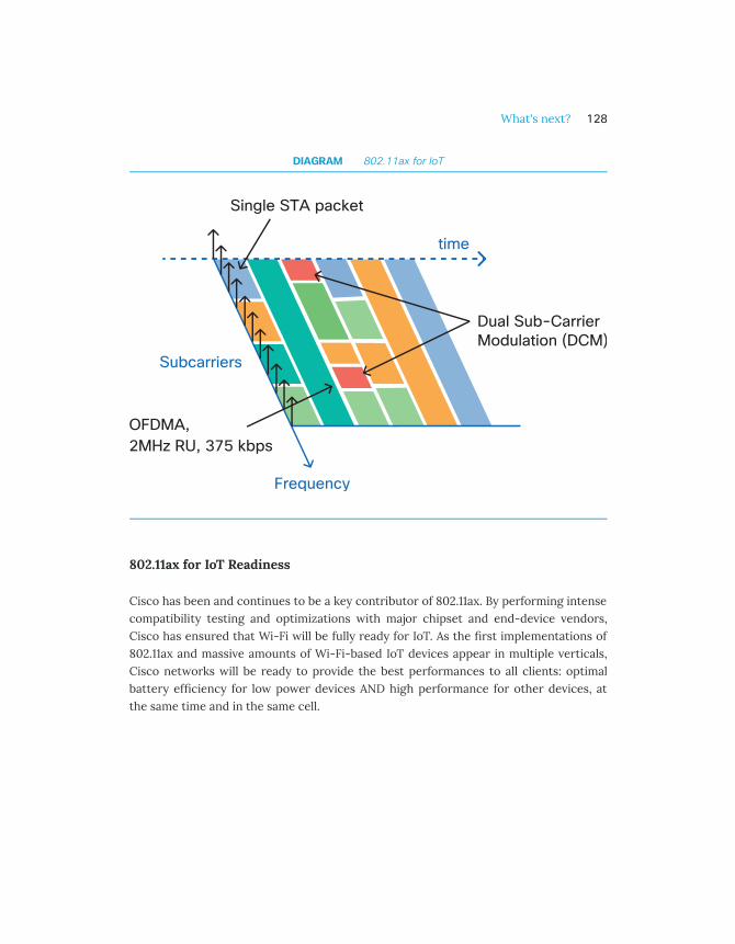
DIAGRAM 802.11ax for IoT
802.11ax for IoT Readiness
Cisco has been and continues to be a key contributor of 802.11ax. By performing intensecompatibility testing and optimizations with major chipset and end-device vendors,Cisco has ensured that Wi-Fi will be fully ready for IoT. As the first implementations of802.11ax and massive amounts of Wi-Fi-based IoT devices appear in multiple verticals,Cisco networks will be ready to provide the best performances to all clients: optimalbattery efficiency for low power devices AND high performance for other devices, atthe same time and in the same cell.
What's next? 128

5G
5G is often presented as the next revolution in cellular communications, and thisreputation may be warranted. In fact, 5G is very different from 4G and previous cellularprotocols. Previously, the 3GPP efforts focused on the radio side of the cellularconnection, providing more bandwidth and better management. By contrast, 5G alsofocuses on the network architecture, introducing and defining concepts ofOrchestration, Policy and network slices (virtual networks). The radio part is notforgotten, but the focus is put on performances more than on technology. The radionetwork has to be fast and efficient, to allow for applications like AugmentedReality/Virtual Reality (AR/VR) that demand high throughput and very low latency) tothrive.
Wi-Fi (802.11ax) as a 5G access technology
In this context, an efficient 802.11ax network may be seen as a 5G Radio AccessTechnology (RAT), if it is designed with performance in mind, as illustrated in the figurebelow. Cisco has been intensely focusing on Wi-Fi efficiency for a long time, providingkey innovations in radio resource management, to provide the best possible channel toeach cell, and features like High-Density Experience (HDX) in order to deliver optimalperformances in high-density environments. This effort continues, and Cisco will makesure that Cisco’s 802.11ax networks qualify as a true 5G-quality radio access technology.
What's next? 129

DIAGRAM 5G use cases with Wi-Fi (802.11ax)
Beyond the Enterprise network: Slices and policies
Performances do not stop at the radio. An efficient network needs to provide trafficsegmentation, but also traffic prioritization and differentiated services. With solutionssuch as SGT/ Trustsec, SD-Access, and DNA Center QoS policies, Cisco networks canalready provide the performances “beyond the radio link” that are required to allow foran optimal experience, even with demanding AR/VR applications.
In a 5G world, traffic will flow seamlessly from cellular networks to enterprise networksand back. This communication means that policies that are valid in the cellular worldshould be translated to enterprise policies and vice versa. Working with multipleexternal and internal partners, Cisco is creating such translation mechanisms that willensure the same quality of experience, whether the user uses a cellular to cellularcommunication, an unlicensed Wi-Fi network, or a combination of both (cellular to Wi-Fi or vice versa).
What's next? 130

5G Timelines
The radio part of 5G specification is expected to be completed by the end of 2018. Theend-to-end architecture part of 5G will come later, likely during 2019. Cisco networksare ready!
What's next? 131

References

Cisco Wireless Portfolio
Cisco Wi-Fi portfolio provides a wide array of options that span across multipledeployment scenarios and use-cases based on functionality and scale. The portfolioconsists of:
Access Points (Indoor, Outdoor and Active Sensor)
Wireless Lan Controllers (Hardware and Virtualized)
Solution components for Network Management, Security, and LocationServices
Cisco Aironet Wireless Access Point
Indoor Access Points
Cisco Aironet 802.11ac Wave 2 access points support the very latest Wi-Fi standards-based technologies. Cisco offers a comprehensive portfolio of access points to meet awide ran ge of deployments needs and scenarios. The diagram below provides a high-level view of the indoor access points portfolio:
1
2
3
References 133

DIAGRAM Current Cisco Aironet Indoor Access Points Portfolio
For more information on Cisco Aironet Access Points see http://cs.co/9004D5Q9mhttp://cs.co/9004D5Q9mhttp://cs.co/9004D5Q9m
References 134

Outdoor Access Points
Cisco Outdoor Access points help extend Wi-Fi connectivity beyond the building aswell as in rugged and hazardous locations, where there is a need for wireless equipmentto be highly resistant to weather and temperature conditions.
For more information on Cisco Aironet Access Points see http://cs.co/9004D5Q9mhttp://cs.co/9004D5Q9mhttp://cs.co/9004D5Q9m
The diagram displays and compares the Cisco Outdoor AP portfolio:
DIAGRAM Current Cisco Aironet Outdoor Access Points Portfolio
Aironet Active Sensor
In addition to indoor and outdoor access points, Cisco has introduced a device that canact as a client to test the Wi-Fi network and provide insights. Cisco Aironet 1800s is anactive, 802.11 a/b/g/n/ac (Wave 2) sensor, functions as a client, and is used inconjunction with Cisco DNA Center to monitor, measure, and troubleshoot the wirelessnetwork performance.
References 135

For more information on the AC power module version of the sensor please seehttp://cs.co/9009D5QiVhttp://cs.co/9009D5QiVhttp://cs.co/9009D5QiV
Cisco Wireless LAN Controller Portfolio
Cisco Wireless LAN Controllers deliver the industry’s most scalable and highestperforming controller solution. These controllers provide unique network security andoptimization for all wireless clients. Cisco offers a comprehensive range of controllersto address different scale, form factor and performance requirements.
For more information on the complete portfolio of Cisco Wireless LAN Controllers, seehttp://cs.co/9004D5QcOhttp://cs.co/9004D5QcOhttp://cs.co/9004D5QcO
DIAGRAM Wireless LAN Controller Portfolio:
References 136
Solution Components
Besides the APs and Wireless LAN Controllers, the components used to build acomplete end-to-end secure wireless solution include the following elements:
• Cisco DNA Center is the hub of Cisco's intent-based network architecture, whichuses AI and machine learning to automate much of the legwork networkadministrators typically do when provisioning networks and their hardware. Seehttp://cs.co/9005D5QY3http://cs.co/9005D5QY3http://cs.co/9005D5QY3
• Cisco Identity Services Engine (ISE) is a security solution that controls accessacross wired, wireless, and VPN connections to the corporate network andenriches DNA Center with user and device details for more actionableintelligence. See http://cs.co/9009D5Qlthttp://cs.co/9009D5Qlthttp://cs.co/9009D5Qlt
• Cisco Stealthwatch Enterprise collects and analyzes flow records and usesmachine learning to quickly adapt to new and changing vulnerabilities.Stealthwatch also integrates with Cisco’s DNA Center network managementsoftware to optimize traffic performance and security of the network. Seehttp://cs.co/9005D5Qlhhttp://cs.co/9005D5Qlhhttp://cs.co/9005D5Qlh
• Cisco Connected Mobile Experiences (CMX) is a software solution that usesclient location from Cisco wireless infrastructure to generate analytics andrelevant services such as Operational Insights, aWIPS, and workplace analytics.See http://cs.co/9004D5Qmyhttp://cs.co/9004D5Qmyhttp://cs.co/9004D5Qmy
• Cisco Umbrella WLAN is cloud security technology which protects againstmalware, botnets, and phishing before a connection is ever made, stoppingthreats earlier. See http://cs.co/9003D5Qmlhttp://cs.co/9003D5Qmlhttp://cs.co/9003D5Qml
• Cisco Prime Infrastructure provides wired and wireless lifecycle management,and application visibility and control. It also offers policy monitoring andtroubleshooting and location-based tracking of mobility devices. Seehttp://cs.co/9006D5QmChttp://cs.co/9006D5QmChttp://cs.co/9006D5QmC
References 137
Acronyms
AAA - Authentication, Authorization, and Accounting
AC - Access Categories
ACK - Acknowledgement
ACL - Access Control List
ACM - Access Control Mandatory
AD - Active Directory
ADDTS - Add Traffic Stream
ADP - Aironet Developer Platform
AF - Assured Forwarding
AoA - Angle of Arrival
AP - Access Points
AR - Augmented Reality
ATF - Air Time Fairness
AVC - Application Visibility and Control
aWIPS - adaptive Wireless Intrusion Prevention System
BLE - Bluetooth Low Energy
BSS - Basic Service Set
References 138

BYOD - Bring Your Own Device
CA - Certificate Authority
CAC - Call Admission Control
CAPWAP - Control And Provisioning of Wireless Access Points
CBRS - Citizens Broadband Radio Service
CC - Common Criteria
CHDM - Coverage Hole Detection and Mitigation
CMX - Connected Mobile Experience
CNSA - Commercial National Security Algorithm
CPU - Central Processing Unit
CSDL - Cisco Secure Development Lifecycle
CSFC - Commercial Solutions For Classified
CWA - Central Web Authentication
DBS - Dynamic Bandwidth Selection
DCM - Dual Sub-Carrier Modulation
DFS - Dynamic Frequency Selection
DHCP - Dynamic Host Configuration Protocol
DMZ - Demilitarized Zone
DNA - Digital Network Architecture
References 139

DNS - Domain Name System
DoD - Department of Defence
DoS - Denial of Service
DPI - Deep Packet Inspection
DPP - Device Provisioning Protocol
DRE - Dual Radiating Element
DSCP - Directed Service Code Point
DTLS - Datagram Transport Layer Security
EAP - Extensible Authentication Protocol
EAP-PEAP - Protected Extensible Authentication Protocol
EAP-TLS - Transport Layer Security
ED-RRM - Event Driven Radio Resource Management
EF - Expedited Forwarding
ELM - Enhanced Local Mode
ESL - Electronic Shelf Labeling
ETA - Encrypted Threat Analytics
FAST - Flexible Authentication via Secure Tunneling
FIPS - Federal Information Processing Standards
FlexDFS - Flexible Dynamic Frequency Selection
References 140

FRA - Flexible Radio Assignment
Gbps - Gigabits per second
GHz - Gigahertz
HA - High Availability
HDK - Hardware Development Kit
HDX - High Density Experience
HTTP- HyperText Transport Protocol
HVAC- Heating, Ventilation, and Air Conditioning
IBN - Intent-Based Networks
IBNS - Identity-Based Networking Services
IDS - Intrusion Detection System
IETF - Internet Engineering Task Force
IoT - Internet of Things
IP - Internet Protocol
IPS - Intrusion Prevention system
IPSK - Identity Preshared Key
ISE - Identity Services Engine
ISO - International Organization for Standardization
IT - Information Technology
References 141

KPI - Key Performance Indicator
L2 - Layer 2
L3 - Layer 3
LAN - Local Area Network
LDAP - Lightweight Directory Access Protocol
LED - light-Emitting Diode
LoRa - Long Range
LSC - Local Signed Certificate
LWA - Local Web Authentication
MBPS - Megabits Per Second
MDM - Mobile Device Manager
mDNS - Multicast Domain Name System
ME - Mobility Express
MGig - MultiGigabit
MHz - Megahertz
MIC - Manufacturer Installed Certificate
MIMO - Multiple-Input and Multiple-Output
MSE - Mobility Services Engine
MU - Multiuser
References 142

MU-MIMO - Multiple User Multiple-Input and Multiple-Output
NBAR - Network-Based Application Recognition
NEMA - National Electrical Manufacturer Association
NFC - Near Field Communication
NUC - Next Unit of Computing
OFDM - Orthogonal Frequency-Division Multiplexing
OFDMA - Orthogonal Frequency-Division Multiple Access
OI - Operational Insights
OSI - Open Systems Interconnection
OWE - Opportunistic Wireless Encryption
PI - Prime Infrastructure
PMF - Protected Management Frames
PnP - Plug and Play
PoE - Power over Ethernet
Pri - Primary
PSIRT - Product Security Incident Response Team
PSK - Pre Shared Key
QoE - Quality of Experience
QoS - Quality of Service
References 143

RA - Route Advertisements
RADIUS - Remote Authentication Dial-In User Service
RAT - Radio Access Technology
RF - Radio Frequency
RFC - Request For Comment
RFID - Radio Frequency Identification
RRM - Radio Resource Management
RSSI - Received Signal Strength Indicator
RX - Receive
SAE - Simultaneous Authentication of Equals
SAgE - Spectrum Analysis Engine
SDA - Software Defined Access
Sec - Secondary
SG - Security Groups
SGT - Scalable Group Tagging
SNMP - Simple Network Management Protocol
SNR - Signal to Noise Ratio
SRE - Single Radiating Element
SSC - Self-Signed Certificate
References 144

SSID - Service Set Identifier
SSL - Secure Sockets Layer
SSO - Stateful Switchover
STA - Station
SUDI - Secure Unique Device Identifier
SW - Software
TCP - Transmission Control Protocol
Ter - Tertiary
TSPEC - Traffic Specification
TWT - Target Wake Time
Tx - Transmit
TxBF - Transmit Beamforming
UC APL - Unified Capabilities Approved Products List
UDP - User Datagram Protocol
UL - Underwriters Laboratories
UP - User Priorities
uPoE - Universal Power Over Ethernet
VLAN - Virtual Local Area Network
VN - Virtual Network
References 145

VNI - Virtual Network Interface
VR - Virtual Reality
WAN - Wireless Area Network
Wi-Fi - Wireless Fidelity
WIPS - Wireless Intrusion Prevention System
WLAN - Wireless Local Area Network
WLAN - ID Wireless LAN Network Identification
WLC - Wireless Lan Controller
WPA - Wi-Fi Protected Access
WUR - Wake Up Radio
YANG - Yet Another Next Generation
References 146

Further Reading
See below for useful references to resources which can provide detailed context andinformation about the various topics covered in this book.
Infrastructure
• Cisco Wireless LAN Controller Software/Technical References - TechnicalDeployment Guides as well Best Practices for most Cisco Wireless technologiescan be found at http://cs.co/9000D5qvMhttp://cs.co/9000D5qvMhttp://cs.co/9000D5qvM
• Cisco Enterprise Mobility Design Guide - overview as well as individual subjectcoverage of design considerations to the management of the Cisco UnifiedWireless Network Architecture can be found at http://cs.co/9005D5qWDhttp://cs.co/9005D5qWDhttp://cs.co/9005D5qWD
• Cisco SD-Access Wireless Design and Deployment Guide – Design andDeployment considerations for the SD-Access Wireless network architecture canbe found at http:/cs.co/9001D5thFhttp:/cs.co/9001D5thFhttp:/cs.co/9001D5thF
• Best Practices to deploy high availability in Wireless LAN Architectures - CiscoLive presentation on wireless design architectures including the Centralized,FlexConnect and Converged Access Deployment models. Link can be found athttp://cs.co/9007D5QZvhttp://cs.co/9007D5QZvhttp://cs.co/9007D5QZv
• Cisco Mobility Express Deployment Guide - overview and valuable instructionsfor designing, implementing and managing Cisco Mobility Express controller forsmall to medium-sized networks and branch offices, can be found athttp://cs.co/9000D5tiQhttp://cs.co/9000D5tiQhttp://cs.co/9000D5tiQ
Radio Excellence
• Cisco Radio Resource Management (RRM) - a White Paper covering the theory,operation, and management of Cisco Radio Resource Management for thewireless network can be found at http://cs.co/9000D5q0qhttp://cs.co/9000D5q0qhttp://cs.co/9000D5q0q
• Cisco CleanAir - product overview page for Cisco CleanAir with links to WhitePapers and deployment guides for CleanAir
References 147

• CleanAir Technology - http://cs.co/9000D5q0qhttp://cs.co/9000D5q0qhttp://cs.co/9000D5q0q
• CleanAir Technology White Paper - http://cs.co/9009D5q7bhttp://cs.co/9009D5q7bhttp://cs.co/9009D5q7b
• CleanAir YouTube Video - http://cs.co/9005D5QwXhttp://cs.co/9005D5QwXhttp://cs.co/9005D5QwX
Cisco Flexible Radio Assignment (FRA)
• Cisco Flexible Radio Assignment Crushes the Competition - blog explaining thebenefits, innovation, and impact the Flexible Radio Architecture has within themarket. Link can be found at http://cs.co/9003D5tUchttp://cs.co/9003D5tUchttp://cs.co/9003D5tUc
• Cisco Radio Resource Management White Paper – technical deep dive sectiondiscussing Flexible Radio Assignment theory and Operation. Link can be found athttp://cs.co/9007D5SrXhttp://cs.co/9007D5SrXhttp://cs.co/9007D5SrX
• Putting the “Flexible” in Flexible Radio Assignment - Cisco “at-a-glance”technology introduction for Cisco FRA. Link can be found at<http://cs.co/9000D5tsQhttp://cs.co/9000D5tsQhttp://cs.co/9000D5tsQ
High-Density Experience (HDX)
• Cisco High-Density Experience “HDX” White Paper - a White Paper introducingand explaining HDX benefits and considerations. Link can be found athttp://cs.co/9008D5Sk0http://cs.co/9008D5Sk0http://cs.co/9008D5Sk0
• HDX Blog Series #2 - Scaling With Turbo Performance - blog discussing thetechnical discussing the benefits of Cisco HDX. Link can be found athttp://cs.co/9000D5tQ0http://cs.co/9000D5tQ0http://cs.co/9000D5tQ0
Infrastructure Security
• Cisco Adaptive wIPS Deployment Guide - deployment guide providing detailedinformation on wIPS security solutions that are provided as part of Cisco UnifiedWireless Solution cab found at http://cs.co/9006D5sPkhttp://cs.co/9006D5sPkhttp://cs.co/9006D5sPk
• Wireless LAN Security and Threat Mitigation - Cisco Live presentation on how toaddress the current state of wireless security & explore the best practices toprotect against unauthorized and uncontrolled wireless access can be found athttp://cs.co/9009D5Qb1http://cs.co/9009D5Qb1http://cs.co/9009D5Qb1
References 148
Policy
• Cisco Unified Wireless QoS - Quality of service (QoS) and Application Visibilityand Control (AVC) in the context of WLAN implementations can be found athttp://cs.co/9004D5suehttp://cs.co/9004D5suehttp://cs.co/9004D5sue
• Wireless Device Profiling and Policy Classification - information about deviceprofiling by WLC and policy classification can be found at http://cs.co/9004D5sRyhttp://cs.co/9004D5sRyhttp://cs.co/9004D5sRy
• Identity PSK Deployment Guide - information about designing, implementing andconfiguring IPSK on Cisco Unified Wireless Networks can be found athttp://cs.co/9004D5sr4http://cs.co/9004D5sr4http://cs.co/9004D5sr4
• Cisco Wireless TrustSec Deployment Guide - TrustSec feature overview, keyfeatures, details about deploying and managing Wireless TrustSec on WLC can befound at http://cs.co/9009D5splhttp://cs.co/9009D5splhttp://cs.co/9009D5spl
Analytics
• Cisco DNA Center - Automation, Analytics and Assurance overview can be foundat http://cs.co/9000D5sgihttp://cs.co/9000D5sgihttp://cs.co/9000D5sgi
• DNA Analytics and Assurance - http://cs.co/9008D5siAhttp://cs.co/9008D5siAhttp://cs.co/9008D5siA
• Wireless Assurance Techwise TV - http://cs.co/9009D5tC9http://cs.co/9009D5tC9http://cs.co/9009D5tC9
Connected Mobility Experiences(CMX)
• Overview of CMX can be found at http://cs.co/9008D5scYhttp://cs.co/9008D5scYhttp://cs.co/9008D5scY
• Cisco Hyperlocation Solution - learn more about Cisco Hyperlocation delivery ofexceptional indoor location accuracy using Wi-Fi at http://cs.co/9001D5sUfhttp://cs.co/9001D5sUfhttp://cs.co/9001D5sUf
• CMX Workplace Analytics - information about Cisco Workplace Analyticssolution can found at http://cs.co/9007D5smdhttp://cs.co/9007D5smdhttp://cs.co/9007D5smd
• Operational Insights - learn more about Operation Insights, how it can helpdefine and manage assets, design workflows for business operation athttp://cs.co/9003D5sozhttp://cs.co/9003D5sozhttp://cs.co/9003D5soz
References 149

What's next
• WPA3 - blog by Cisco’s VP of Enterprise networking can be found athttp://cs.co/9002D5swjhttp://cs.co/9002D5swjhttp://cs.co/9002D5swj
• 802.11ax technology White Paper – can be found at http://cs.co/9009D5smLhttp://cs.co/9009D5smLhttp://cs.co/9009D5smL
• Internet of Things (IoT) - Cisco IOT technology page can be found athttp://cs.co/9004D5soMhttp://cs.co/9004D5soMhttp://cs.co/9004D5soM
• 5G - Cisco 5G newsroom with links to current Cisco 5G content can be found athttp://cs.co/9007D5sqVhttp://cs.co/9007D5sqVhttp://cs.co/9007D5sqV
References 150


![Deploying Cisco Wireless Enterprise Networks · 2017-07-10 · Deploying Cisco Wireless Enterprise Networks Version: 7.0 [ Total Questions: 61 ] Download 2017 EP 300-365 Dump PDF](https://img.dokumen.tips/doc/110x75/5eccff51d8862845760e31e7/deploying-cisco-wireless-enterprise-2017-07-10-deploying-cisco-wireless-enterprise.jpg)