Embed Size (px)
Citation preview
Cisco Press201 W 103rd StreetIndianapolis, IN 46290
Cisco CCNP Routing Exam Certification Guide
Clare Gough
chpt_01.book Page iii Thursday, December 21, 2000 6:22 PM
iv
Cisco CCNP Routing Exam Certification Guide
Clare Gough
Copyright © 2001 Cisco Press
Cisco Press logo is a trademark of Cisco Systems, Inc.
Published by:Cisco Press201 West 103rd StreetIndianapolis, IN 46290 USA
All rights reserved. No part of this book may be reproduced or transmitted in any form or by any means, electronic or mechanical, including photocopying, recording, or by any information storage and retrieval system, without written per-mission from the publisher, except for the inclusion of brief quotations in a review.
Printed in the United States of America 1 2 3 4 5 6 7 8 9 0
Library of Congress Cataloging-in-Publication Number: 00-105173
ISBN: 1-58720-001-5
Warning and Disclaimer
This book is designed to provide information about Cisco routing. Every effort has been made to make this book as complete and as accurate as possible, but no warranty or fitness is implied.
The information is provided on an "as is" basis. The author, Cisco Press, and Cisco Systems, Inc., shall have neither lia-bility nor responsibility to any person or entity with respect to any loss or damages arising from the information con-tained in this book or from the use of the discs or programs that may accompany it.
The opinions expressed in this book belong to the author and are not necessarily those of Cisco Systems, Inc.
Trademark Acknowledgments
All terms mentioned in this book that are known to be trademarks or service marks have been appropriately capitalized. Cisco Press or Cisco Systems, Inc., cannot attest to the accuracy of this information. Use of a term in this book should not be regarded as affecting the validity of any trademark or service mark.
Feedback Information
At Cisco Press, our goal is to create in-depth technical books of the highest quality and value. Each book is crafted with care and precision, undergoing rigorous development that involves the unique expertise of members from the profes-sional technical community.
Readers’ feedback is a natural continuation of this process. If you have any comments regarding how we could improve the quality of this book, or otherwise alter it to better suit your needs, you can contact us through e-mail at [email protected]. Please make sure to include the book title and ISBN in your message.
chpt_01.book Page iv Thursday, December 21, 2000 6:22 PM
v
We greatly appreciate your assistance.
Publisher John WaitEditor-in-Chief John KaneExecutive Editor Brett BartowCisco Systems Program Manager Bob AnsteyManaging Editor Patrick KanouseAcquisitions Editor Amy LewisDevelopment Editor Andrew CuppProduction Editor Marc FowlerCopy Editor Krista HansingTechnical Editors Jorge Aragon
Steve GifkinsMartin WalshawSteve Wisniewski
CD-ROM Question Authors David BarnesMartin Walshaw
CD-ROM Technical Editors Steve GifkinsMike Truett
Team Coordinator Tammi RossBook Designer Gina RexrodeCover Designer Louisa KlucznikProduction Team Octal Publishing, Inc.Indexer Lisa Stumpf
Corporate HeadquartersCisco Systems, Inc.170 West Tasman DriveSan Jose, CA 95134-1706USAhttp://www.cisco.comTel: 408 526-4000
800 553-NETS (6387)Fax: 408 526-4100
European HeadquartersCisco Systems Europe11 Rue Camille Desmoulins92782 Issy-les-Moulineaux Cedex 9Francehttp://www-europe.cisco.comTel: 33 1 58 04 60 00Fax: 33 1 58 04 61 00
Americas HeadquartersCisco Systems, Inc.170 West Tasman DriveSan Jose, CA 95134-1706USAhttp://www.cisco.comTel: 408 526-7660Fax: 408 527-0883
Asia Pacific HeadquartersCisco Systems Australia, Pty., LtdLevel 17, 99 Walker StreetNorth SydneyNSW 2059 Australiahttp://www.cisco.comTel: +61 2 8448 7100Fax: +61 2 9957 4350
Copyright © 2000, Cisco Systems, Inc. All rights reserved. Access Registrar, AccessPath, Are You Ready, ATM Director, Browse with Me, CCDA, CCDE, CCDP, CCIE, CCNA,CCNP, CCSI, CD-PAC, CiscoLink, the Cisco NetWorks logo, the Cisco Powered Network logo, Cisco Systems Networking Academy, Fast Step, FireRunner, Follow Me Browsing,FormShare, GigaStack, IGX, Intelligence in the Optical Core, Internet Quotient, IP/VC, iQ Breakthrough, iQ Expertise, iQ FastTrack, iQuick Study, iQ Readiness Scorecard, The iQLogo, Kernel Proxy, MGX, Natural Network Viewer, Network Registrar, the Networkers logo, Packet, PIX, Point and Click Internetworking, Policy Builder, RateMUX, ReyMaster,ReyView, ScriptShare, Secure Script, Shop with Me, SlideCast, SMARTnet, SVX, TrafficDirector, TransPath, VlanDirector, Voice LAN, Wavelength Router, Workgroup Director,and Workgroup Stack are trademarks of Cisco Systems, Inc.; Changing the Way We Work, Live, Play, and Learn, Empowering the Internet Generation, are service marks of CiscoSystems, Inc.; and Aironet, ASIST, BPX, Catalyst, Cisco, the Cisco Certified Internetwork Expert Logo, Cisco IOS, the Cisco IOS logo, Cisco Press, Cisco Systems, Cisco SystemsCapital, the Cisco Systems logo, Collision Free, Enterprise/Solver, EtherChannel, EtherSwitch, FastHub, FastLink, FastPAD, IOS, IP/TV, IPX, LightStream, LightSwitch, MICA,NetRanger, Post-Routing, Pre-Routing, Registrar, StrataView Plus, Stratm, SwitchProbe, TeleRouter, are registered trademarks of Cisco Systems, Inc. or its affiliates in the U.S. andcertain other countries.
All other brands, names, or trademarks mentioned in this document or Web site are the property of their respective owners. The use of the word partner does not imply a partnershiprelationship between Cisco and any other company. (0010R)
Cisco Systems has more than 200 offices in the following countries. Addresses, phone numbers, and fax numbers are listed on the Cisco Web site at www.cisco.com/go/offices
Argentina • Australia • Austria • Belgium • Brazil • Bulgaria • Canada • Chile • China • Colombia • CostaRica • Croatia • Czech Republic • Denmark • Dubai, UAE • Finland • France • Germany • Greece • HongKong • Hungary • India • Indonesia • Ireland Israel • Italy • Japan • Korea • Luxembourg • Malaysia •Mexico • The Netherlands • New Zealand • Norway • Peru • Philippines Poland • Portugal • Puerto Rico •Romania • Russia • Saudi Arabia • Scotland • Singapore • Slovakia • Slovenia • South Africa • Spain Sweden• Switzerland • Taiwan • Thailand • Turkey • Ukraine • United Kingdom • United States • Venezuela • Vietnam• Zimbabwe
chpt_01.book Page v Thursday, December 21, 2000 6:22 PM
vi
About the Author
Clare Gough
is a Cisco Certified Internetworking Engineer(CCIE #2893) and was a Cisco Certified Systems Instructor for the ICRC, ACRC, CIT, CLSC, and CID courses. She holds a master's degree in education and a mas-ter's degree in information systems. Over the last 15 years, she has developed and taught a variety of networking and internetworking courses throughout the world for Digital Equipment Co. and various Cisco training partners. She moved from England in 1991 and now lives in San Francisco with her family.
About the Technical Reviewers
Jorge Aragon
(CCIE #5567) is a network engineer with Perot Systems Corporation (PSC) in Dallas, Texas. He holds a bachelor of science degree in electrical engineering from the National Polytechnic Institute in Mexico, and has a master of science degree in telecommunications from the University of Pittsburgh. He also holds an MCSE certification and several of Cisco's specializations. Jorge is part of the PSC Global Infrastructure team, where he designs, implements, and troubleshoots LAN and WAN networks for clients in multiple industries across the globe. He enjoys spending time with his wife and children, reading, jogging, and practicing martial arts. Jorge can be reached at [email protected].
Steve Gifkins
is a CCIE and CCSI of four and five years, respectively. He is based in the United Kingdom, where he runs his own independent Cisco-only consulting and training business. He is married with no children, and his hob-bies include anything to do with outdoor life. Having retired with a knee injury from playing active sports such as squash, rugby, and soccer, he has taken up new hobbies in horse eventing and show jumping. In addition, he enjoys skiing and hill scrambling.
Martin Walshaw
is a CCIE (#5629), CCNP, and CCDP. He is a systems engineer working for Cisco Systems in the enterprise line of business in South Africa. His areas of specialty are multiservice (voice and video) as well as secu-rity, which keeps him busy both night and day. During the last 12 years or so, Martin has dabbled in many aspects of the IT industry, ranging from programming in RPG III and Cobol to PC sales. When Martin is not working, he likes to spend all his available time with his wife, Val, and his son, Joshua. Without their patience, understanding, and sup-port, projects such as this would not be possible.
Steve Wisniewski
is CCNP certified and has a master of science degree from Stevens Institute of Technology in Telecom Management. Steve works for Lehmqan Brothers as a senior implementation specialist implementing Cisco switches and routers. He has also previously edited several other Cisco books and recently authored a book entitled
Network Administration
. Steve lives in East Brunswick, New Jersey, with his wife, Ellen.
chpt_01.book Page vi Thursday, December 21, 2000 6:22 PM

vii
Dedications
This book is dedicated to David and Jack, who make everything worthwhile.
chpt_01.book Page vii Thursday, December 21, 2000 6:22 PM

viii
Acknowledgments
All books are the product of a team, and I have been blessed with a dedicated and professional team, whose expertise in their given areas have made this book. Over the course of writing this book and its predecessor, I have come to think of members of this team as friends as well as colleagues. In particular, I would like to thank John Kane, the editor in chief, and Drew Cupp, the development editor, who were always there with solutions and support. My thanks go also to Amy Lewis for her understanding and flexibility. Of course, I thank all the members of the Cisco Press team helping to bring this book together, including the project editor, Marc Fowler, and the copy editor, Krista Hansing.
The technical editors, Steve Gifkins, Martin Walshaw, Jorge Aragon, and Steve Wisniewski, were extremely thor-ough. Their careful attention to detail and constructive advice improved this book immeasurably. I would particu-larly like to thank Jorge Aragon and Steve Wisniewski who went the extra mile by testing configurations and producing output screens.
I would also like to thank Wendell Odom, who led me into the art of book writing and has ever generously shared his expertise.
Of course, I am immensely grateful to my husband, David, for his support, in spite of the long hours demanded by this book, and to our small son, Jack, for making me laugh and see the joy of life.
chpt_01.book Page viii Thursday, December 21, 2000 6:22 PM
ix
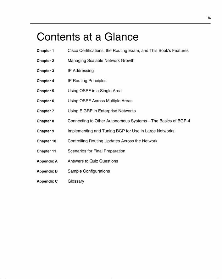
Contents at a Glance
Chapter 1
Cisco Certifications, the Routing Exam, and This Book's Features
Chapter 2
Managing Scalable Network Growth
Chapter 3
IP Addressing
Chapter 4
IP Routing Principles
Chapter 5
Using OSPF in a Single Area
Chapter 6
Using OSPF Across Multiple Areas
Chapter 7
Using EIGRP in Enterprise Networks
Chapter 8
Connecting to Other Autonomous Systems—The Basics of BGP-4
Chapter 9
Implementing and Tuning BGP for Use in Large Networks
Chapter 10
Controlling Routing Updates Across the Network
Chapter 11
Scenarios for Final Preparation
Appendix A
Answers to Quiz Questions
Appendix B
Sample Configurations
Appendix C
Glossary
chpt_01.book Page ix Thursday, December 21, 2000 6:22 PM
x
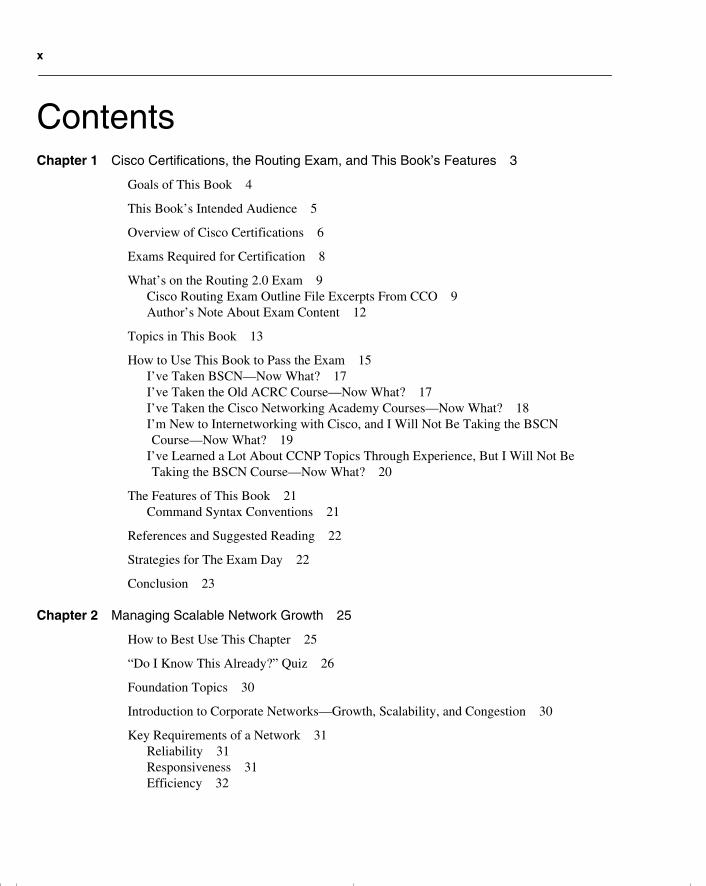
Contents
Chapter 1
Cisco Certifications, the Routing Exam, and This Book’s Features 3
Goals of This Book 4
This Book’s Intended Audience 5
Overview of Cisco Certifications 6
Exams Required for Certification 8
What’s on the Routing 2.0 Exam 9Cisco Routing Exam Outline File Excerpts From CCO 9Author’s Note About Exam Content 12
Topics in This Book 13
How to Use This Book to Pass the Exam 15I’ve Taken BSCN—Now What? 17I’ve Taken the Old ACRC Course—Now What? 17I’ve Taken the Cisco Networking Academy Courses—Now What? 18I’m New to Internetworking with Cisco, and I Will Not Be Taking the BSCN Course—Now What? 19
I’ve Learned a Lot About CCNP Topics Through Experience, But I Will Not Be Taking the BSCN Course—Now What? 20
The Features of This Book 21Command Syntax Conventions 21
References and Suggested Reading 22
Strategies for The Exam Day 22
Conclusion 23
Chapter 2
Managing Scalable Network Growth 25
How to Best Use This Chapter 25
“Do I Know This Already?” Quiz 26
Foundation Topics 30
Introduction to Corporate Networks—Growth, Scalability, and Congestion 30
Key Requirements of a Network 31Reliability 31Responsiveness 31Efficiency 32
chpt_01.book Page x Thursday, December 21, 2000 6:22 PM
xi
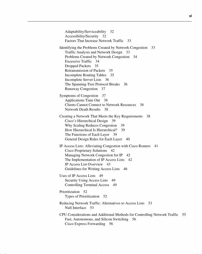
Adaptability/Serviceability 32Accessibility/Security 32Factors That Increase Network Traffic 33
Identifying the Problems Created by Network Congestion 33Traffic Analysis and Network Design 33Problems Created by Network Congestion 34Excessive Traffic 34Dropped Packets 35Retransmission of Packets 35Incomplete Routing Tables 35Incomplete Server Lists 36The Spanning-Tree Protocol Breaks 36Runaway Congestion 37
Symptoms of Congestion 37Applications Time Out 38Clients Cannot Connect to Network Resources 38Network Death Results 38
Creating a Network That Meets the Key Requirements 38Cisco’s Hierarchical Design 39Why Scaling Reduces Congestion 39How Hierarchical Is Hierarchical? 39The Functions of Each Layer 39General Design Rules for Each Layer 40
IP Access Lists: Alleviating Congestion with Cisco Routers 41Cisco Proprietary Solutions 42Managing Network Congestion for IP 42The Implementation of IP Access Lists 42IP Access List Overview 43Guidelines for Writing Access Lists 46
Uses of IP Access Lists 49Security Using Access Lists 49Controlling Terminal Access 49
Prioritization 52Types of Prioritization 52
Reducing Network Traffic: Alternatives to Access Lists 53Null Interface 53
CPU Considerations and Additional Methods for Controlling Network Traffic 55Fast, Autonomous, and Silicon Switching 56Cisco Express Forwarding 56
chpt_01.book Page xi Thursday, December 21, 2000 6:22 PM

xii
Placement of Client/Server 57Design Principles of a Client/Server Network 57IP Helper Address 57Enhanced Interior Gateway Routing Protocol 58Tunneling into IP 59
Conclusion 62
Foundation Summary 63
Chapter Glossary 66
Q&A 67
Scenarios 72
Scenario 2-1 72
Scenario 2-2 74
Scenario 2-3 74
Scenario Answers 75
Scenario 2-1 Answers 75
Scenario 2-2 Answers 76
Scenario 2-3 Answers 77
Chapter 3
IP Addressing 81
How to Best Use This Chapter 81
“Do I Know This Already?” Quiz 82
Foundation Topics 86
Introduction: What Is a Layer 3 Address and How Does It Affect My Life? 86Case Study 86The Need for Layer 3 Addressing 86The Network and How It Is Addressed 87
An IP Address 89Why IP? 89Network and Host Addressing 90The Internet Mask 90The Subnet Mask 92
Prefix Routing/CIDR 96A Definition of Prefix Routing/CIDR 96Problems with IP Addressing and the Internet 97
chpt_01.book Page xii Thursday, December 21, 2000 6:22 PM
xiii
Variable-Length Subnet Masks 101An Example of VLSM 101Routing Protocols That Support VLSM 101Rules for VLSM 102The Advantages of Using VLSM 102
Summarization 107The Advantages of Summarization 110Other Solutions to Address Exhaustion 111Configuring Summarization 111Automatic Summarization 111Manual Summarization 111Discontiguous Networks 112Optimizing the IP Address Space 114
Designing IP Networks 116Keys Points to Remember When Designing an IP Network 118Private Addresses on the Internet 121
Connecting to the Outside World 123The Main Features of NAT 125
Conclusion 127
Foundation Summary 128
IP Addressing Summary 128
Summary of CIDR 128
An Example of the Use of CIDR 129
Rules for VLSM 130
Advantages of Summarization 130
Chapter Glossary 131
Q&A 134
Scenarios 140
Scenario 3-1 140
Scenario 3-2 142
Scenario 3-3 142
Scenario Answers 144
Scenario 3-1 Answers 144
Scenario 3-2 Answers 148
Scenario 3-3 Answers 151
chpt_01.book Page xiii Thursday, December 21, 2000 6:22 PM
xiv
Chapter 4
IP Routing Principles 155
How to Best Use This Chapter 155
“Do I Know This Already?” Quiz 156
Foundation Topics 160
Introduction: What Is a Routing Protocol? 160Case Study 160What Is a Routing Protocol? 160The Network Field 162The Outgoing Interface Field 163The Metric Field 163The Next Logical Hop Field 164The show ip route Command 165How the Routing Table Is Kept Current and Correct 166Switching Versus Routing 167
Distance Vector and Link-State Routing Protocols 170Distance Vector Routing Protocols 171Link-State Routing Protocols 172Interior and Exterior Routing Protocols 174
RIP Version 1 175
IGRP 176
OSPF 177Key Attributes of OSPF 178Path Selection Between Routing Protocols 179
Convergence 181RIPv1 Convergence 181IGRP Convergence 182EIGRP Convergence 182OSPF Convergence 183
Conclusion 183
Foundation Summary 184
Chapter Glossary 187
Q&A 191
Scenarios 196
Scenario 4-1 196
Scenario 4-2 198
chpt_01.book Page xiv Thursday, December 21, 2000 6:22 PM
xv
Scenario Answers 200
Scenario 4-1 Answers 200
Scenario 4-2 Answers 201
Chapter 5
Using OSPF in a Single Area 203
How to Best Use This Chapter 203
“Do I Know This Already?” Quiz 204
Foundation Topics 209
Introduction: What Is OSPF? 209Case Study 209OSPF Terminology 210
OSPF Neighbors 212OSPF Network Topologies 212The Hello Packet 214Adjacent OSPF Neighbors 215The Designated Router 216How OSPF Builds Its Routing Table 219Choosing the Shortest Path First and Building the Routing Table 228
OSPF Across Nonbroadcast Multiaccess Networks 229Which Topology to Choose? 230Subinterfaces 230
Configuring OSPF in a Single Area 232Required Commands for Configuring OSPF on an Internal Router 232Options for Configuring OSPF on an Internal Router 235A Working Configuration of OSPF on a Single Router 238
Configuring OSPF over an NBMA Topology 240Configuring OSPF in NBMA Mode 240Configuring OSPF in Point-to-Multipoint Mode 242Configuring OSPF in Broadcast Mode 242Configuring OSPF in Point-to-Point Mode on a Frame Relay Subinterface 243
Checking the Configuration of OSPF on a Single Router 244The show ip ospf Command 245The show ip ospf database Command 246The show ip ospf interface Command 248The show ip ospf neighbor Command 250The show ip protocols Command 253The show ip route Command 255
Conclusion 255
chpt_01.book Page xv Thursday, December 21, 2000 6:22 PM
xvi
Foundation Summary 256
Routing Table 259
Learning a New Route 259
Command Summaries 261
Chapter Glossary 262
Q&A 264
Scenarios 269
Scenario 5-1 269
Scenario 5-2 270
Scenario 5-3 270
Scenario Answers 272
Scenario 5-1 Answers 272
Scenario 5-2 Answers 276
Scenario 5-3 Answers 276
Chapter 6
Using OSPF Across Multiple Areas 281
How to Best Use This Chapter 281
“Do I Know This Already?” Quiz 282
Foundation Topics 287
OSPF in a Multiple Area Network 287Case Study 287Why Multiple Areas? 287How to Determine Area Boundaries 288Problems with OSPF in a Single Area 288
OSPF Areas 289OSPF Within an Area 289Router Types 289The Link-State Advertisements 291OSPF Path Selection Between Areas 293Calculating the Cost of a Path to Another Area 294The Different Types of Areas 295
Design Considerations in Multiple Area OSPF 297Summarization 298The Virtual Link 298OSPF over an NBMA Network 299
chpt_01.book Page xvi Thursday, December 21, 2000 6:22 PM
xvii
Configuring OSPF on a Multiarea Network 300Configuration Commands for a Multiarea OSPF Network 300A Working Configuration of OSPF on a Multiarea Network 312
Checking the Configuration of OSPF on a Multiarea Network 313The show ip ospf border-routers Command 314The show ip ospf virtual-links Command 315
Conclusion 316
Foundation Summary 317
OSPF Routers 317
Link-State Advertisements 318
Routing Table Codes 318
Command Summaries 319
Q&A 320
Scenarios 325
Scenario 6-1 325
Scenario 6-2 327
Scenario 6-3 329
Scenario Answers 330
Scenario 6-1 Answers 330
Scenario 6-2 Answers 332
Scenario 6-3 Answers 334
Chapter 7
Using EIGRP in Enterprise Networks 337
How to Best Use This Chapter 337
“Do I Know This Already?” Quiz 338
Foundation Topics 343
Introduction: EIGRP in an Enterprise Network 343Case Study 343EIGRP Defined 343
Operation of EIGRP 344How EIGRP Works 345The Hello Protocol 348EIGRP Metrics 352
chpt_01.book Page xvii Thursday, December 21, 2000 6:22 PM
xviii
The DUAL Finite-State Machine 353Updating the Routing Table in Passive Mode with DUAL 354Updating the Routing Table in Active Mode with DUAL 355Scaling EIGRP 363Solutions to EIGRP Scaling Issues 364
Configuring EIGRP 366The Required Commands for Configuring EIGRP 366The Optional Commands for Configuring EIGRP 368Configuring EIGRP for IPX 374Configuring EIGRP for AppleTalk 376
Verifying the EIGRP Operation 376The show ip eigrp neighbors Command 377The show ip eigrp topology Command 378The show ip eigrp traffic Command 379The debug Commands 380
Conclusion 381
Foundation Summary 382
Chapter Glossary 383
Q&A 386
Scenarios 391
Scenario 7-1 391
Scenario 7-2 392
Scenario Answers 394
Scenario 7-1 Answers 394
Scenario 7-2 Answers 395
Chapter 8
Connecting to Other Autonomous Systems—The Basics of BGP-4 397
How to Best Use This Chapter 397
“Do I Know This Already?” Quiz 398
Foundation Topics 402
Introduction: BGP-4 and Communicating with other Autonomous Systems 402Case Study 402
BGP-4 Operation 403An Autonomous System Defined 404Characteristics of BGP-4 405
chpt_01.book Page xviii Thursday, December 21, 2000 6:22 PM
xix
Overview of the BGP-4 Operation 405Message Types 406Synchronization 408CIDR and Route Aggregation 410BGP-4 Policy-Based Routing 411Route Selection Process 419
Basic Configuration Commands to Connect to Another Autonomous System 421Starting the Routing Process 422Defining the Networks to Be Advertised 422Identifying Neighbors and Defining Peer Groups 422Forcing the Next-Hop Address 422Disabling Synchronization 423Aggregating Routes 423
Managing and Verifying the BGP-4 Configuration 424
When to Use BGP-4 425
When Not to Use BGP-4 425
Alternative Methods of Connecting to an ISP 426
Conclusion 427
Foundation Summary 428
The Key Features of BGP-4 428
Chapter Glossary 434
Q&A 436
Scenarios 441
Scenario 8-1 441
Scenario 8-2 442
Scenario 8-3 443
Scenario Answers 446
Scenario 8-1 Answers 446
Scenario 8-2 Answers 447
Scenario 8-3 Answers 448
Chapter 9
Implementing and Tuning BGP for Use in Large Networks 453
How to Best Use This Chapter 453
chpt_01.book Page xix Thursday, December 21, 2000 6:22 PM
xx
“Do I Know This Already?” Quiz 454
Foundation Topics 458
Introduction—Communicating with Other Autonomous Systems with BGP-4 458Case Study 458
Designing and Configuring a Scalable BGP-4 Network 459Why Does BGP-4 Require a Fully Meshed Network? 460Route Reflectors: The Solution to a Fully Meshed IBGP-4 Network 461
Controlling BGP-4 Traffic 470How Prefix Lists Work 471How to Configure a BGP-4 Prefix List 472Verifying the Prefix List Configuration 473
Redundant Connections into the Internet—Multihoming 474
Multiple Connections into the Internet 475Receiving Routing Information from the Internet 475
Determining the BGP-4 Path by Tuning the Attributes 478Commands to Tune BGP-4—Using the Local Preference and Weight Attributes 478
Verifying the Configuration of Attributes 481
Redistribution Between the IGP and BGP-4 484Advertising Routes from an IGP into BGP-4 485Advertising Routes from a BGP-4 into an IGP 485
Conclusion 487
Foundation Summary 488
Route Reflectors 489
Prefix Lists 490
Routing Updates from Multihomed Connections to the Internet 491
BGP-4 show Commands 492
Chapter Glossary 493
Q&A 494
Scenarios 498
Scenario 9-1 498
Scenario 9-2 499
Scenario 9-3 500
Scenario Answers 502
chpt_01.book Page xx Thursday, December 21, 2000 6:22 PM
xxi
Scenario 9-1 Answers 502
Scenario 9-2 Answers 503
Scenario 9-3 Answers 504
Chapter 10
Controlling Routing Updates Across the Network 507
How to Best Use This Chapter 507
“Do I Know This Already?” Quiz 508
Foundation Topics 513
Introduction: Controlling the Routing Updates Using Redistribution and Filtering 513Case Study 513
Redistribution Between Routing Protocols 513Controlling Routing Updates 515The Main Features of Redistribution 518
Configuring Redistribution 528Generic Steps Required for Redistribution 528Redistribution Configuration Syntax 529Static Routes 535
Controlling Routing Updates with Filtering 539Redistribution Examples 541
Policy-Based Routing Using Route Maps 547Uses for Route Maps 548Characteristics of Route Maps 548 The Route Map Command Syntax 549Policy-Based Routing Using Route Maps 550
Configuring Route Maps for Policy Routing 554The match Commands for Policy Routing with Route Maps 554Route Maps, Policy Routing, and Route Switching 557
Verifying, Maintaining, and Troubleshooting the Redistribution Implementation 558traceroute 558Extended ping 559Specific Commands for Monitoring Policy-Routing Configurations 559
Conclusion 560
Foundation Summary 561
Methods of Controlling Routing Updates 561
Automatic Redistribution Between Routing Protocols 562
chpt_01.book Page xxi Thursday, December 21, 2000 6:22 PM
xxii
Default Administrative Distance 563
The Logic Used in Distribute Lists 563
Chapter Glossary 564
Q&A 566
Scenarios 571
Scenario 10-1 571
Scenario 10-2 572
Scenario Answers 574
Scenario 10-1 Answers 574
Scenario 10-2 Answers 576
Chapter 11
Scenarios for Final Preparation 579
Further Study for Final Preparation 579
How to Best Use This Chapter 580
Scenarios 581
Scenario 11-1 581
Scenario 11-2 582
Scenario 11-3 583
Scenario Answers 585
Scenario 11-1 Answers 585
Scenario 11-2 Answers 587
Scenario 11-3 Answers 589
Three-Part Scenarios 592
Scenario 11-4 592Scenario 11-4, Part A—Planning 592Solutions to Scenario 11-4, Part A—Planning 597Scenario 11-4, Part B—Configuration 601Solutions to Scenario 11-4, Part B—Configuration 602Scenario 11-4 Part C—Verification and Questions 603Solutions to Scenario 11-4, Part C—Verification and Questions 634
Scenario 11-5 638Scenario 11-5, Part A—Planning 638
chpt_01.book Page xxii Thursday, December 21, 2000 6:22 PM
xxiii
Solutions to Scenario 11-5, Part A—Planning 640Scenario 11-5, Part B—Configuration 642Solutions to Scenario 11-5, Part B—Configuration 642Scenario 11-5 Part C—Verification and Questions 645Solutions to Scenario 11-5, Part C—Verification and Questions 679
Appendix A
Answers to Quiz Questions 685
Chapter 2 685Chapter 2 “Do I Know This Already?” Quiz Answers 685Chapter 2 “Q&A” Answers 688
Chapter 3 693Chapter 3 “Do I Know This Already?” Quiz Answers 693Chapter 3 “Q&A” Answers 695
Chapter 4 699Chapter 4 “Do I Know This Already?” Quiz Answers 699Chapter 4 “Q&A” Answers 702
Chapter 5 706Chapter 5 “Do I Know This Already?” Quiz Answers 706Chapter 5 “Q&A” Answers 708
Chapter 6 712Chapter 6 “Do I Know This Already?” Quiz Answers 712Chapter 6 “Q&A” Answers 716
Chapter 7 720Chapter 7 “Do I Know This Already?” Quiz Answers 720Chapter 7 “Q&A” Answers 723
Chapter 8 727Chapter 8 “Do I Know This Already?” Quiz Answers 727Chapter 8 “Q&A” Answers 729
Chapter 9 734Chapter 9 “Do I Know This Already?” Quiz Answers 734Chapter 9 “Q&A” Answers 736
Chapter 10 741Chapter 10 “Do I Know This Already?” Quiz Answers 741Chapter 10 “Q&A” Answers 744
Appendix B
Sample Configurations 751
Configuration 1—OSPF and Dialup Links 752Commands Showing the Configuration 1 Working Network 756
chpt_01.book Page xxiii Thursday, December 21, 2000 6:22 PM

xxiv
Configuration 2—BGP-4 and Route Maps 758Commands Showing the Configuration 2 Working Network 761
Appendix C
Glossary 767
Classless Interdomain Routing Conversion Table 810
Index 810
chpt_01.book Page xxiv Thursday, December 21, 2000 6:22 PM

chpt_01.book Page xxv Thursday, December 21, 2000 6:22 PM

chpt_01.book Page 2 Thursday, December 21, 2000 6:22 PM
C
H
A
P
T
E
R
1
Cisco Certifications, the Routing Exam, and This Book’s Features
The Cisco Certified Network Professional (CCNP) and Cisco Certified Design Professional (CCDP) certifications on the Routing and Switching career track are becoming increasingly popular. These certifications have as their foundation the Cisco Certifed Network Associate (CCNA) certification and these profesional-level certifications form the second rung in the ladder to the coveted Cisco Certified Internetwork Expert (CCIE) certification. The Routing 2.0 exam (#640-503) is one of three exams that you must pass to become a CCNP or CCDP. This book will help you prepare for that exam. Professional-level certification opens doors to career opportunities and is a prerequisite for other Cisco certifications as well. Generally, passing the Routing 2.0 exam means that you have mastered the concepts and implementation skills necessary to build a complex IP network of Cisco routers.
NOTE
You must pass the Routing 2.0 exam (among other exams) to acheive either the CCNP or the CCDP certification. The CCNP and CCDP certifications are often referred to as the
professional-level certifications
throughout this book wherever the information at hand applies to CCNP and CCDP. For more information on the differences between the two professional-level certifications and the latest on Cisco exams and certifications, begin at the Cisco Career Certification page (www.cisco.com/warp/public/10/wwtraining/certprog/
index.html) at Cisco Connection Online (CCO).
The Routing exam is a computer-based exam, with multiple-choice, fill-in-the-blank, and list-in-order style questions. The exam can be taken at any Sylvan Prometric testing center (1-800-829-NETS, www.2test.com). The exam will take about 75 minutes and has approximately 60 questions. You should check with Sylvan Prometric for the exact length of the exam. (Be aware that when you register for the exam, you might be told to allow a certain amount of time to take the exam that is longer than the testing time indicated by the testing software when you begin. This is because Sylvan Prometrics wants you to allow for some time to get settled and take the tutorial on the testing engine.)
NOTE
This book uses the terms
Routing exam
and
Routing 2.0 exam
. These terms are used
synonomously and refer to the the exam #640-503.
chpt_01.book Page 3 Thursday, December 21, 2000 6:22 PM
4
Chapter 1: Cisco Certifications, the Routing Exam, and This Book’s Features
The Routing 2.0 exam is not an easy exam. This is to say that you cannot simply read one book and expect to pass it. In fact, the exam is surprisingly difficult; this is so that Cisco can be sure that everyone who passes the test thoroughly understands the subject matter on a conceptual level and is not just good at exams. More importantly, Cisco is very interested in making sure that passing proves that you have the skills to actually implement the features, not just talk about them. The exam is difficult in subject matter and also in format. You can expect multiple-choice questions—some with multiple answers. You can also expect questions requiring you to pick the correct answer from output screens and configurations.
Another difficult aspect of the exam format is that, to ensure that you know your stuff, the exam does
not
allow you to go back and change an answer. Those CCNP/CCDP candidates who are unsure about the question will be forced to guess rather than have an extra 15 minutes to think about it at the end of the exam. Those who really know most of the answers will be rewarded by Cisco’s attempts to preserve the integrety of the CCNP/CCDP certification. The professional-level certification will mean to all that you are highly qualified at the subject at hand.
Although this is a difficult exam, most networking professionals can expect to pass if they meet the prerequisites and spend the proper amount of time on training, on-the-job experience, and study. Like most certification exams, you might not pass the first time. Taking the exam a second time, however, might be easier because you have an idea of what to expect.
There are many questions on the Routing 2.0 exam that you might already know through your professional background and experiences, if you meet the prerequisites. This book offers you the opportunity to solidify and build on that knowledge as you make your final preparations to take the Routing exam. The concepts and commands covered on the exam are not secrets locked in some vault—the information is available in many places and forms, including this book. So, although the exam is difficult, passing is certainly attainable with study.
Goals of This Book
The goals for this book became somewhat obvious to me after considering the exam itself, as well as Cisco’s exam philosophy. The first goal came straight from Cisco, who asked that I write a book that not only helps you pass the exam, but that also ensures that you really understand the concepts and implementation details. The second goal of this book is that the content should be the most comprehensive coverage of Routing 2.0 exam-related topics available, without too much coverage of topics not on the exam. The third and ultimate goal is to get you from where you are today to the point that you can confidently pass the Routing 2.0 exam. Therefore, all this book’s features, which are outlined in this chapter, are geared toward helping you discover the IP routing topics that are on the Routing exam, where you have a knowledge deficiency in these topics, and what you need to know to master these topics.
chpt_01.book Page 4 Thursday, December 21, 2000 6:22 PM
This Book’s Intended Audience
5
This Book’s Intended Audience
Although the only prerequisite for CCNP certificaion is CCNA status, and the only prerequisite for CCDP certification is CCNA and CCDA status, Cisco does not expect you to be able to pass the professional-level exams (such as the Routing exam) without training and experience. This is why Cisco’s recommended training for CCNP/CCDP involves an official Cisco course. For the routing knowledge required of a CCNP/CCDP, Cisco recommends a course called Building Cisco Scalable Networks (BSCN).
As stated on the Cisco web site, the BSCN course is targeted toward enterprise network engineers (including systems engineers [SEs], customers, and resellers) who are responsible for network administration and implementation. The targeted audience performs one or more of the following tasks:
•
Install and configure network devices
•
Design and implement large enterprise networks
• Add services/applications to an existing network, and determine what router configurations are required to support the new services/applications
• Improve traffic flow, reliability, redundancy, and performance through the network
NOTE BSCN replaces the old Advanced Cisco Router Configuration (ACRC) course, much as the new Routing 2.0 exam (#640-503) replaces the old ACRC exam (#640-403).
This book is a final stage preparation tool. Therefore, this book will be most effective as a study resource after you have taken the BSCN course or have acquired an equivalent level of on-the-job experience and training. The following are the prerequisites for the BSCN course, and, for all practical purposes, should be considered prerequsites for using this book effectively:
• Working knowledge of the OSI reference model and the hierarchical model
• Understanding of internetworking fundamentals
• Ability to operate and configure a Cisco IOS device
• Working knowledge of the TCP/IP stack and how to configure a routed protocol such as IP
• Understanding of distance vector routing protocol operation and configuring Routing Information Protocol (RIP) and Interior Gateway Routing Protocol (IGRP)
• Ability to determine when to use static and default routes, and how to enable them on a Cisco router
• Ability to display and interpret a Cisco router routing table
chpt_01.book Page 5 Thursday, December 21, 2000 6:22 PM
6 Chapter 1: Cisco Certifications, the Routing Exam, and This Book’s Features
• Ability to enable a WAN serial connection
• Ability to configure Frame Relay permanent virtual circuits (PVCs) on interfaces and subinterfaces
• Ability to configure an IP standard and extended access list
• Ability to verify router configurations with available tools such as show and debug commands
The ideal audience for this book is someone who has attended the Interconnecting Cisco Networking Devices (ICND) course (or the retired Introduction to Cisco Router Configuration [ICRC] course), has acheived CCNA status, and has attended the BSCN course, or who has an equivalent level of on-the-job training and experience with Cisco switches and routers.
Cisco highly recommends that you take courses to support each certification level, but it also recognizes that attending courses might not be an option for everyone. Therefore, if you find yourself struggling with CCNA-level knowledge as you work through this book, you might want to review a copy of the Interconnecting Cisco Networking Devices coursebook (ISBN 1-57870-111-2) from Cisco Press. Similarly, if you want course details at the CCNP/CCDP level about routing, review the Building Scalable Cisco Networks coursebook (ISBN 1-57870-228-3), also from Cisco Press.
Overview of Cisco CertificationsCisco’s main motivation behind the current certification program is to provide a means of measuring the skills of people working for Cisco resellers and certified partners. Cisco fulfills only a small portion of its orders via direct sale from Cisco; normally, a Cisco reseller is involved. Also, Cisco has not attempted to become the primary source for consulting and implementation services for network deployment using Cisco products, preferring instead to use partners as much as possible. With that business model, there is a great need to distinguish, ensure, and certify the skill levels of the partner company’s employees.
The CCIE program was Cisco’s first foray into certifications. Introduced in 1994, the CCIE was designed to be one of the most respected, difficult-to-achieve certifications. To certify, a written test (also given at Sylvan Prometric) must be passed, and then a two-day hands-on lab test is administered by Cisco. Cisco does not publish numbers on pass/fail rates for CCIE or the other certifications, but rumors have the failure rate on all lab test takers at over 50 percent, with failure rate for first-time lab takers at over 80 percent.
Certifying resellers and services partners, by using the number of employed CCIEs as the gauge, worked well originally, partly because Cisco had far fewer partners than today. Cisco uses the number of CCIEs on staff as part of the criteria in determining the level of partner status for the company, which in turn dictates the discount received by the reseller when buying from Cisco. (For more insight into reseller certification, go to CCO, at www.cisco.com.) This practice continues to be a good way for Cisco to judge the commitment to having people with
chpt_01.book Page 6 Thursday, December 21, 2000 6:22 PM
Overview of Cisco Certifications 7
proven Cisco skills on staff, which in turn improves customer satisfaction—and customer satisfaction is tied to every Cisco executive’s goals.
The CCIE certification became inadequate for helping certify resellers and other partners because, among other factors, the number of partners increased disproportionately to the difficulty of the CCIE exam. For instance, there are around 4500 CCIEs worldwide and 2500 resellers (and not all the CCIEs work for resellers, of course). Furthermore, many resellers that do not perform services do not require the extreme expertise of a CCIE on staff, other than to get a better discount. What Cisco needed were certifications that were less rigorous than CCIE and that would allow Cisco more granularity in judging the skills on staff at a partner company. So, Cisco started an entire Cisco Career Certification program, of which CCNP and CCDP are a part.
Cisco developed Routing and Switching career tracks, WAN Switching career tracks, and several specialization career tracks. Thus far, the Routing and Switching career tracks, which begin with CCNA/CCDA certification, have proven to be the most popular and make up the heart of Cisco certification. The Routing exam required for CCNP/CCDP certification is part of the Routing and Switching career tracks.
Two categories of certifications exist—one to certify implementation skills and the other to certify design skills. Resellers working in a presale environment need more design skills, whereas services companies need more implementation skills. So, the CCNA and CCNP are implementation-oriented certifications, whereas CCDA and CCDP are design-oriented certifications.
Rather than requiring just one level of certification besides CCIE, Cisco created two additional levels—an associate level and a professional level. The associate level (CCNA/CCDA) is the most basic, and the professional level (CCNP/CCDP) is the intermediate level between CCNA and CCIE.
Several of the certifications require other certifications as a prerequisite. For instance, CCNP certification requires that you have CCNA certification. Also, CCDP requires both CCDA and CCNA certification. CCIE, however, does not require any other certification prior to the written and lab tests. CCIE certification is extremely difficult, however, and it is unlikely that someone could acheive that level of certification without a level of experience and training equalled in attaining and practicing associate- and professional-level certification.
Cisco certifications have taken on a much larger role and importance in the networking industry in recent years. From a career standpoint, Cisco certification can certainly be used to help you get a new job or a promotion. Or, you can have certification added to your performance evaluation plan and then justify a raise based on passing an exam. If you are looking for a new job, not only might passing an exam help you land the job, but it may actually help you make more money.
chpt_01.book Page 7 Thursday, December 21, 2000 6:22 PM
8 Chapter 1: Cisco Certifications, the Routing Exam, and This Book’s Features
Exams Required for CertificationIn 2000, Cisco initiated a major revamping of the career certification exams. Several new exams were unveiled, and the Routing exam was one of those. The Routing 2.0 exam replaced the old ACRC exam; this is why the exam is called Routing 2.0 sometimes, even though there was never a Routing 1.0 exam.
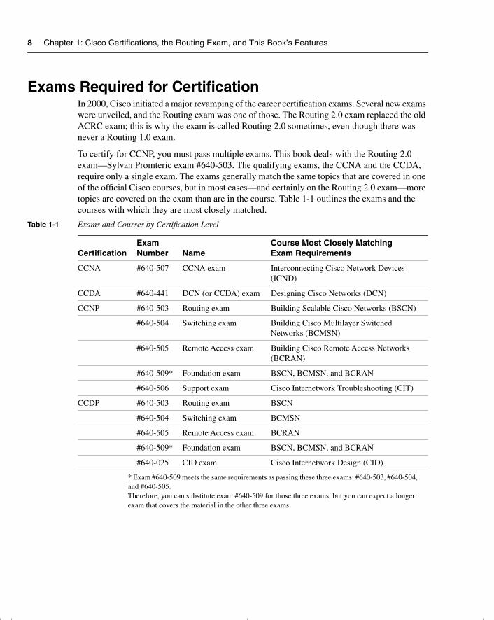
To certify for CCNP, you must pass multiple exams. This book deals with the Routing 2.0 exam—Sylvan Promteric exam #640-503. The qualifying exams, the CCNA and the CCDA, require only a single exam. The exams generally match the same topics that are covered in one of the official Cisco courses, but in most cases—and certainly on the Routing 2.0 exam—more topics are covered on the exam than are in the course. Table 1-1 outlines the exams and the courses with which they are most closely matched.
Table 1-1 Exams and Courses by Certification Level
CertificationExamNumber Name
Course Most Closely MatchingExam Requirements
CCNA #640-507 CCNA exam Interconnecting Cisco Network Devices (ICND)
CCDA #640-441 DCN (or CCDA) exam Designing Cisco Networks (DCN)
CCNP #640-503 Routing exam Building Scalable Cisco Networks (BSCN)
#640-504 Switching exam Building Cisco Multilayer Switched Networks (BCMSN)
#640-505 Remote Access exam Building Cisco Remote Access Networks (BCRAN)
#640-509* Foundation exam BSCN, BCMSN, and BCRAN
#640-506 Support exam Cisco Internetwork Troubleshooting (CIT)
CCDP #640-503 Routing exam BSCN
#640-504 Switching exam BCMSN
#640-505 Remote Access exam BCRAN
#640-509* Foundation exam BSCN, BCMSN, and BCRAN
#640-025 CID exam Cisco Internetwork Design (CID)
* Exam #640-509 meets the same requirements as passing these three exams: #640-503, #640-504, and #640-505. Therefore, you can substitute exam #640-509 for those three exams, but you can expect a longer exam that covers the material in the other three exams.
chpt_01.book Page 8 Thursday, December 21, 2000 6:22 PM
What’s on the Routing 2.0 Exam 9
Be cautioned that, although the exam coverage and course coverage are similar, there are no guarantees that if you know absolutely everything in the course, you will pass the test. Cisco is moving more toward the certifications being tied to technology, not to specific courses; note that the exam names do not match the course names as they previously did. As you can see, a Cisco Press Exam Certification Guide will help prepare you for the certification exam beyond how the courses can, with the added guidance of stressing the most important exam items and coverage of other topics not taught in the prerequisite courses. Cisco also maintains the right to change the exam content at will to ensure that the exam is current and fair.
What’s on the Routing 2.0 ExamEvery one of us would like to know exactly what is on the Routing 2.0 exam, as well as the other Cisco certification exams. Well, to be honest, exactly what is on the exam is a very closely guarded secret. Only those who write the questions for Cisco and who have access to the entire question database truly know what is entirely on the exam.
The Routing 2.0 exam content that is made known by Cisco to the public is general. You can find a list of Cisco exams and the general outline that accompanies each exam at www.cisco.com/warp/public/10/wwtraining/certprog/testing/exam_list.htm.
You will have to download the outline for each exam. The following section contains excerpts from the Routing exam outline downloaded file.
Cisco Routing Exam Outline File Excerpts From CCOGiven your experience, this outline and guide will help you with the best methods of preparation for the Cisco Career Certifications exam.
The BSCN course is the recommended method of preparation for the Routing exam.
The topic areas listed in this outline are general guidelines for the type of content that is likely to appear on the exam. However, please be advised that other relevant or related topic areas may also appear.
The Routing (640-503) exam will contain a combination of the following topics:
1 Routing principles:
• List the key information routers need to route data.
• Describe classful and classless routing protocols.
• Compare distance vector and link-state routing protocol operation.
• Describe the use of the fields in a routing table.
• Given a preconfigured laboratory network, discover the topology, analyze the routing table, and test connectivity using accepted troubleshooting techniques.
chpt_01.book Page 9 Thursday, December 21, 2000 6:22 PM
10 Chapter 1: Cisco Certifications, the Routing Exam, and This Book’s Features
2 Extending IP addresses:
• Given an IP address range, use variable-length subnet masks (VLSMs) to extend the use of the IP addresses.
• Given a network plan that includes IP addressing, explain whether route summarization is possible.
• Configure an IP helper address to manage broadcasts.
3 Configuring Open Shortest Path First (OSPF) in a single area:
• Explain why OSPF is better than RIP in a large internetwork.
• Explain how OSPF discovers, chooses, and maintains routes.
• Explain how OSPF operates in a single-area nonbroadcast multiaccess (NBMA) environment.
• Configure OSPF for proper operation in a single area.
• Verify OSPF operation in a single area.
• Given an addressing scheme and other laboratory parameters, configure a single-area OSPF environment, and verify proper operation (within described guidelines) of your routers.
• Given an addressing scheme and other laboratory parameters, configure single-area OSPF in an NBMA environment, and verify proper operation (within described guidelines) of your routers.
4 Interconnecting multiple OSPF areas:
• Describe the issues with interconnecting multiple areas, and tell how OSPF addresses each.
• Explain the differences between the possible types of areas, routers, and LSAs.
• Explain how OSPF supports the use of VLSM.
• Explain how OSPF supports the use of route summarization in multiple areas.
• Explain how OSPF operates in a multiple-area NBMA environment.
• Configure a multiarea OSPF network.
• Verify OSPF operation in multiple areas.
• Given an addressing scheme and other laboratory parameters, configure a multiple-area OSPF environment, and verify proper operation (within described guidelines) of your routers.
chpt_01.book Page 10 Thursday, December 21, 2000 6:22 PM
What’s on the Routing 2.0 Exam 11
5 Configuring Enhanced IGRP (EIGRP):
• Describe EIGRP features and operation.
• Explain how EIGRP discovers, chooses, and maintains routes.
• Explain how EIGRP supports the use of VLSM.
• Explain how EIGRP operates in an NBMA environment.
• Explain how EIGRP supports the use of route summarization.
• Describe how EIGRP supports large networks.
• Configure EIGRP.
• Verify EIGRP operation.
• Given a set of network requirements, configure an EIGRP environment, and verify proper operation (within described guidelines) of your routers.
• Given a set of network requirements, configure EIGRP in an NBMA environment, and verify proper operation (within described guidelines) of your routers.
6 Configuring Basic Border Gateway Protocol (BGP):
• Describe BGP features and operation.
• Describe how to connect to another autonomous system using an alternative to BGP, static routes.
• Explain how BGP policy-based routing functions within an autonomous system.
• Explain how BGP peering functions.
• Describe BGP communities and peer groups.
• Describe and configure external and internal BGP.
• Describe BGP synchronization.
• Given a set of network requirements, configure a BGP environment, and verify proper operation (within described guidelines) of your routers.
7 Implementing BGP in scalable networks:
• Describe the scalability problems associated with internal BGP.
• Explain and configure BGP route reflectors.
• Describe and configure policy control in BGP using prefix lists.
• Describe methods to connect to multiple ISPs using BGP.
• Explain the use of redistribution between BGP and Interior Gateway Protocols (IGPs).
chpt_01.book Page 11 Thursday, December 21, 2000 6:22 PM
12 Chapter 1: Cisco Certifications, the Routing Exam, and This Book’s Features
• Given a set of network requirements, configure a multihomed BGP environment, and verify proper operation (within described guidelines) of your routers.
8 Optimizing routing update operation:
• Select and configure the different ways to control routing update traffic.
• Configure route redistribution in a network that does not have redundant paths between dissimilar routing processes.
• Configure route redistribution in a network that has redundant paths between dissimilar routing processes.
• Resolve path selection problems that result in a redistributed network.
• Verify route redistribution.
• Configure policy-based routing using route maps.
• Given a set of network requirements, configure redistribution between different routing domains, and verify proper operation (within described guidelines) of your routers.
• Given a set of network requirements, configure policy-based routing within your pod, and verify proper operation (within described guidelines) of your routers.
9 Implementing scalability features in your internetwork:
• Given a set of network requirements, configure many of the features discussed in the course, and verify proper operation (within described guidelines) of your routers.
Author’s Note About Exam ContentAs Cisco’s authorized external publishing company, Cisco Press is the only publisher that is partnered with Cisco. Cisco has shared other information with Cisco Press, part of which includes some details that are expected to be posted on Cisco’s web site at a later date. At press time, Cisco had not finalized what other details about the exam will be posted on its web site, so I cannot list any of those details here. Fortunately, what does get posted by Cisco will be easily available to you! I encourage you to check Cisco’s web site for the latest information on the exam.
Some points I would like to make about the exam as it relates to this book are as follows:
• If we at Cisco Press believe that a topic is definitely on the exam, it is covered in Chapters 2 through 10.
• For topics that we at Cisco Press believe have only a remote (but still possible) chance of being in Cisco’s Routing 2.0 exam question database, the topic is covered briefly in the body of the book, but it is clearly stated that it is not part of the exam study. These marginal topics are placed in the body of the book so that the topics are in context.
chpt_01.book Page 12 Thursday, December 21, 2000 6:22 PM
Topics in This Book 13
• If we at Cisco Press believe that a topic is simply not in the Cisco Routing 2.0 exam question database, then it is not covered in this book. The only exception would be topics that must be explained to make a topic that is on the exam more understandable. Again, this is indicated within the book.
Topics in This BookThe list that follows outlines the topics that will be the focus of the exam. The topics are listed corresponding to the chapters in which they are covered.
• Chapter 2, “Managing Scalable Network Growth”
— The key requirements of a network
— The problem of network congestion
— The symptoms of network congestion
— Methods of controlling network traffic
— Access lists, how to restrict vty access, and uses of access lists
— Alternatives to access lists
• Chapter 3, “IP Addressing”
— Prefix routing
— The use of VLSM and its application
— The use, application, and configuration of summarization
— Key points in the design of an IP network
— How to connect to the outside world and use NAT and private addresses
• Chapter 4, “IP Routing Principles”
— The requirements of the routing process
— The routing table
— The differences between a classful and classless routing protocol
— The difference between distance vector and link-state routing protocol
— How routing tables are maintained
— Path selection
• Chapter 5, “Using OSPF in a Single Area”
— How a link-state routing protocol (such as OSPF) discovers, chooses, and maintains links
chpt_01.book Page 13 Thursday, December 21, 2000 6:22 PM
14 Chapter 1: Cisco Certifications, the Routing Exam, and This Book’s Features
— How OSPF operates in a single NBMA area WAN
— How to configure OSPF in a single area
— How to verify the operation of and troubleshoot an OSPF network
• Chapter 6, “Using OSPF Across Multiple Areas”
— The issues with interconnecting multiple OSPF areas
— The differences between the possible types of areas, routers, and LSAs
— How OSPF operates across multiple areas using NBMA
— How OSPF supports the use of VLSM and summarization
— The Cisco commands for implementing OSPF for multiple areas
• Chapter 7, “Using EIGRP in Enterprise Networks”
— The features and operation of EIGRP
— How EIGRP discovers, chooses, and maintains routes
— How EIGRP supports the use of VLSM and summarization
— How EIGRP functions in an NBMA environment
— How EIGRP supports large networks
— How to configure EIGRP, both in an enterprise network and in an NBMA network
— How to verify an EIGRP configuration
• Chapter 8, “Connecting to Other Autonomous Systems—The Basics of BGP-4”
— The features and operation of BGP
— BGP terminology
— Design issues with BGP
— BGP communities, peer groups, and the peering function
— The configuration of internal and external BGP
— How to verify the BGP configuration
• Chapter 9, “Implementing and Tuning BGP for Use in Large Networks”
— Scaling internal BGP
— Configuring route reflectors
— Determining policy control using prefix lists
chpt_01.book Page 14 Thursday, December 21, 2000 6:22 PM
How to Use This Book to Pass the Exam 15
— Connecting to multiple ISPs
— Redistributing between interior routing protocols and BGP
— Configuring and verifying the BGP configuration
• Chapter 10, “Controlling Routing Updates Across the Network”
— Selecting and configuring different ways to control routing updates
— Configuring route redistribution in networks with and without redundant paths between dissimilar routing processes
— Resolving problems occuring in a redistributed network
— Configuring policy-based route maps
— Verifying and troubleshooting redistribution and policy-based routing
• Chapter 11, “Scenarios for Final Preparation”
— Chapter 11 contains two scenarios that test you on various topics covered throughout the book instead of concentrating on a particular technology. This challenges your understanding at a profound level and places the topics in context.
How to Use This Book to Pass the ExamOne way to use this book is to start at the beginning and read it cover to cover. While that would certainly help you prepare, most people do not have that much time to spare, particularly if they already have mastered some of the topics in the book. However, if you want to read the entire book and answer all the CD-ROM questions, then that is a great way to prepare!
For the rest of you, you might want to consider different strategies for how best to use this book, depending on what training and experience you already have. With its prechapter analysis quizzes and chapter-ending summary sections and questions, as well as its traditional foundation sections, this book is designed to help you get the most out of the time you take to study.
The core material for the Routing 2.0 exam is covered in Chapters 2 through 10. At the beginning of each chapter, you are instructed on how to make best use of your time reading that chapter, assuming that you are not going to read every detail. The instructions on how to use each chapter is outlined in a figure in each chapter. That figure is repeated here as Figure 1-1.
chpt_01.book Page 15 Thursday, December 21, 2000 6:22 PM
16 Chapter 1: Cisco Certifications, the Routing Exam, and This Book’s Features
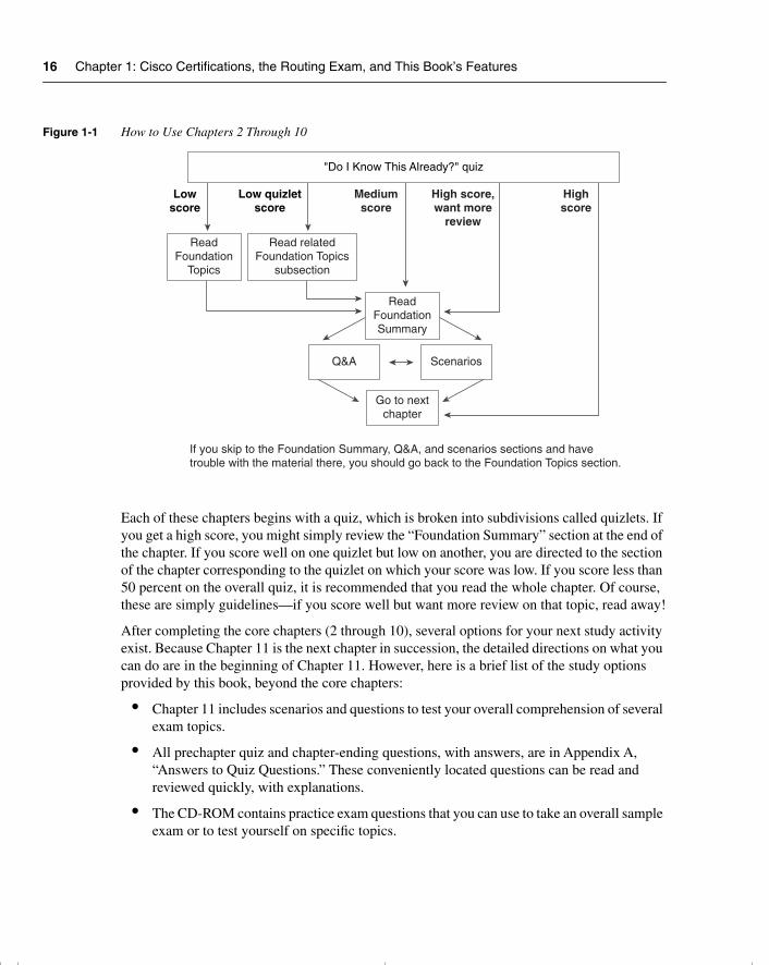
Figure 1-1 How to Use Chapters 2 Through 10
Each of these chapters begins with a quiz, which is broken into subdivisions called quizlets. If you get a high score, you might simply review the “Foundation Summary” section at the end of the chapter. If you score well on one quizlet but low on another, you are directed to the section of the chapter corresponding to the quizlet on which your score was low. If you score less than 50 percent on the overall quiz, it is recommended that you read the whole chapter. Of course, these are simply guidelines—if you score well but want more review on that topic, read away!
After completing the core chapters (2 through 10), several options for your next study activity exist. Because Chapter 11 is the next chapter in succession, the detailed directions on what you can do are in the beginning of Chapter 11. However, here is a brief list of the study options provided by this book, beyond the core chapters:
• Chapter 11 includes scenarios and questions to test your overall comprehension of several exam topics.
• All prechapter quiz and chapter-ending questions, with answers, are in Appendix A, “Answers to Quiz Questions.” These conveniently located questions can be read and reviewed quickly, with explanations.
• The CD-ROM contains practice exam questions that you can use to take an overall sample exam or to test yourself on specific topics.
Lowscore
Low quizletscore
Mediumscore
High score,want more
review
Highscore
"Do I Know This Already?" quiz
ReadFoundation
Topics
Read relatedFoundation Topics
subsection
ReadFoundationSummary
Q&A Scenarios
Go to nextchapter
If you skip to the Foundation Summary, Q&A, and scenarios sections and havetrouble with the material there, you should go back to the Foundation Topics section.
chpt_01.book Page 16 Thursday, December 21, 2000 6:22 PM
How to Use This Book to Pass the Exam 17
• Each core chapter has a “Foundation Summary” section near the end that contains concise tables and information for final review.
• Where appropriate, each chapter has a glossary for the terms introduced in that chapter. The chapter glossaries and Appendix C, “Glossary,” are also good study aids.
When you are preparing for the Routing 2.0 exam, the guidelines at the beginning of each chapter should be adequate no matter what your level of knowledge is. However, if you would like some additional guidance, the remainder of this section gives a few additional strategies for study, based on how you have prepared before buying this book. So, find the section that most closely matches your background in the next few pages, and read about some additional ideas to help you prepare.
There are basically five different categories of students:
• Those who have taken the BSCN course
• Those who have taken the ACRC course
• Those who have attended the Cisco Networking Academies
• Those who will not be taking any classes and have not had much experience
• Those who will not be taking any classes but have some experience
I’ve Taken BSCN—Now What?Well, first let me say that you’ve taken the best path to prepare yourself! However, let me temper that with the fact that if you retain more than 50 percent of what you heard in class, then you are an extraordinary person! That said, in my opinion, you need to follow these strategies:
• Strategy 1—Use this book exactly as described in the opening pages of Chapters 2 through 10. Each of the core chapters begins with a quiz that helps you assess what you need to study. It then directs you to the appropriate sections in the chapter rather than requiring you to read the entirety of each chapter.
• Strategy 2—Use the directions at the beginning of Chapter 11 to direct your final study before the exam. Chapter 11 is designed to review many concepts; in addition, it outlines a good process for study in the days leading up to your exam.
By using these strategies, you will fill in your gaps in knowledge and will be confident taking your Routing 2.0 exam.
I’ve Taken the Old ACRC Course—Now What?It is true that the current version of the exam is a closer match to the BSCN class. However, if you were to compare the BSCN and ACRC courses, you would find there is much more in common than is different. In fact, more than half of the ACRC topics are retained in the BSCN
chpt_01.book Page 17 Thursday, December 21, 2000 6:22 PM

18 Chapter 1: Cisco Certifications, the Routing Exam, and This Book’s Features
course. Of course, if you retain more than 50 percent of what you heard in class, then you are an extraordinary person, so you probably still need to fill in some holes in your knowledge base. For you, the following strategies will be most helpful:
• Strategy 1—Begin with a review of Chapters 8 through 10. These chapters consist of almost completely new material of the Routing exam and should be studied in depth. Do not skip the configuration sections—they are very important.
• Strategy 2—Use this book exactly as described in the opening pages of Chapters 2 through 10. Each of the core chapters begins with a quiz that helps you assess what you need to study. It then directs you to the appropriate sections in the chapter rather than requiring you to read the entirety of each chapter. In fact, you probably should even use Chapters 8 through 10 this way, in spite of having read them already, because that will validate what you have learned.
• Strategy 3—Make it a point to read the sections of the book that cover topics not found in the ACRC course. Other than almost the entirety of Chapters 8 through 10 of this book, the subjects that you will want to make sure to read are as follows:
— Chapter 3—Routing table analysis
— Chapter 4—Hierarchical routing
— Chapter 5—OSPF in an NBMA network, and OSPF operation
— Chapter 6—OSPF across multiple areas
— Chapter 7—Details of the EIGRP operation, particularly across an NBMA network, and design considerations in building a scalable network
• Strategy 4—Use the directions at the beginning of Chapter 11 to direct your final study before the exam. Chapter 11 is designed to review many concepts; in addition, it outlines a good process for study in the days leading up to your exam.
Therefore, compared to those who have taken BSCN, you should not require a lot of additional study time. The ACRC course did a great job of explaining the basics, and this book will help you fill in the gaps to confidently prepare to pass the exam!
I’ve Taken the Cisco Networking Academy Courses—Now What?First, I’ll start by congratulating you on having the foresight to get into the Cisco Networking Academy program—we need more people that can make this stuff work! For those of you who are did not take the Cisco Networking Academy track and are wondering what it is, visit www.cisco.com/warp/public/779/edu/academy/ for more information. Thankfully, the Networking Academy curriculum does a great job of preparing you with the skills and knowledge that you need to pass the Routing exam. Unfortunately, your study was probably spread over several semesters, and possibly over a couple years. So, the details that you do not
chpt_01.book Page 18 Thursday, December 21, 2000 6:22 PM
How to Use This Book to Pass the Exam 19
use frequently may have been forgotten! On to the strategies for success on CCNP/CCDP—and, in particular, the Routing exam:
• Strategy 1—Pull out your Networking Academy curriculum and notes, and reread them. Exciting, huh? Nevertheless, most people’s memory is exercised better by seeing familiar material, and even more so when that person wrote it down himself. If you have ever taken a test and pictured in your mind where the answer was on your page of notes, then you can recall the information easily.
• Strategy 2—Use this book exactly as described in the opening pages of Chapters 2 through 10. Each of the core chapters begins with a quiz that helps you assess what you need to study. It then directs you to the appropriate sections in the chapter rather than requiring you to read the entirety of each chapter.
• Strategy 3—Make it a point to read the sections that cover some of the theory and conceptual sections, and some of the standards. The biggest reason for that is that the Networking Academy is more oriented toward building skills, not theoretical knowledge. The subjects that I suggest are as follows:
— Chapter 2—From the beginning of the “Foundation Topics” section up to the beginning of the routing table analysis section
— Chapter 3—The section on VLSM and router summarization
— The sections on operations in all the other chapters
• Strategy 4—Use the directions at the beginning of Chapter 11 to direct your final study before the exam. Chapter 11 is designed to review many concepts; in addition, it outlines a good process for study in the days leading up to your exam.
This book is designed to help you sift through the topics and choose the areas for study that you need to focus on in a timely fashion. Congratulations on your Networking Academy work and CCNA/CCDA certification—now add the CCNP or CCDP certification to take away any doubt in the minds of prospective employers that you know Cisco products and technology.
I’m New to Internetworking with Cisco, and I Will Not Be Taking the BSCN Course—Now What?
You can take and pass the Routing 2.0 exam without taking any courses. Cisco wants you to take the recommended courses for all the exams, though. Cisco’s motivation is not to make more money, because the company does not actually deliver the training. Instead, Cisco’s motivation is that it truly believes that the more people understand Cisco products, ultimately the happier the customers will be, and the more products Cisco will sell. In addition, Cisco believes that its official training is the best way to teach people about its products, so Cisco wants you to take the classes.
chpt_01.book Page 19 Thursday, December 21, 2000 6:22 PM
20 Chapter 1: Cisco Certifications, the Routing Exam, and This Book’s Features
If you are not taking the course, there is no reason to worry! However, truthfully, you will need more than just this book to prepare. Cisco Press publishes the Building Scalable Cisco Networks coursebook (ISBN 1-57870-228-3), which is a book version of the BSCN course. The figures are exactly like those in the course, and the text comes from the course material and is even expanded and reorganized to work well in book format. Therefore, if you can’t take the course, your best substitute is the Building Scalable Cisco Networks coursebook. This book will build on the BSCN material and help you assess what further study you need to pass the Routing exam. Here are my strategy suggestions for your case:
• Strategy 1—Read the Building Scalable Cisco Networks coursebook. Although Routing 2.0 is not entirely a course-based test, the BSCN course is listed as the recommended course for the Routing exam.
• Strategy 2—After reading BSCN, use this book exactly as described in the opening pages of Chapters 2 through 10. Each of the core chapters begins with a quiz that helps you assess what you need to study. It then directs you to the appropriate sections in the chapter rather than requiring you to read the entirety of each chapter.
• Strategy 3—Use the directions at the beginning of Chapter 11 to direct your final study before the exam. Chapter 11 is designed to review many concepts; in addition, it outlines a good process for study in the days leading up to your exam.
I’ve Learned a Lot About CCNP Topics Through Experience, But I Will Not Be Taking the BSCN Course—Now What?
If you feel like you know a fair amount about professional-level routing topics already (at a level that makes taking the BSCN course not very worthwhile), but you are worried about the few topics that you simply just have not worked with, then this strategy is for you. This book is designed to help you figure out what IP routing topics you need some help with, and then help you learn about them. Here is the simple strategy for you:
• Strategy 1—Use this book exactly as described in the opening pages of Chapters 2 through 10. Each of the core chapters begins with a quiz that helps you assess what you need to study. It then directs you to the appropriate sections in the chapter rather than requiring you to read the entirety of each chapter.
• Strategy 2—Use the directions at the beginning of Chapter 11 to direct your final study before the exam. Chapter 11 is designed to review many concepts; in addition, it outlines a good process for study in the days leading up to your exam.
You will be able to fill in the gaps in your knowledge this way, and not risk being bored in the BSCN class when it covers the topics that you already know!
chpt_01.book Page 20 Thursday, December 21, 2000 6:22 PM
The Features of This Book 21
The Features of This BookAfter this brief introductory chapter, there are 10 chapters and three appendixes in this book. Each core chapter starts with a “Do I Know This Already?” quiz that allows you to decide how much time you need to devote to studying the subject at hand. Next, the “Foundation Topics” (the core material of the chapter) are presented. This section is the bulk of each chapter. At the end of each chapter, you will find a “Foundation Summary” section that is a collection of tables and quick-reference material that can be used as the last-minute review notes. Also contained in the “Foundation Summary” section of each chapter is a Chapter Glossary, which defines important terms used in the chapter. Reviewing the Chapter Glossary along with the rest of the “Foundation Summary” makes for excellent late-stage exam preparation. Each core chapter also has a “Q&A” section of review questions that test you on the chapter’s contents. Finally, each core chapter contains a “Scenarios” section that tests you further on the material at hand.
The appendixes contain materials for your reference. Appendix A contains the answers to each chapter’s “Do I Know This Already?” and “Q&A” quizzes. The answers to the “Scenarios” questions can be found at the end of each chapter.
This book is also accompanied by a CD-ROM that offers multiple-choice questions out of the entire book’s content. Each question in the CD-ROM refers you to the chapter and section it is drawn from. The CD-ROM also contains a file called “Job Aids and Supplements.” This material is taken from the BSCN course itself and provides further reference material on the following topics:
• IP addresses and subnetting
• Addressing review
• IP access lists
• Configuration and output examples of the following:
— OSPF
— EIGRP
— BGP-4
— Route optimization
Command Syntax ConventionsThe conventions used to present command syntax in this book are the same conventions used in the Cisco IOS Command Reference, as follows:
• Boldface indicates commands and keywords that are entered literally as shown. In examples (not syntax), boldface indicates user input (for example, a show command).
• Italics indicates arguments for which you supply values.
chpt_01.book Page 21 Thursday, December 21, 2000 6:22 PM
22 Chapter 1: Cisco Certifications, the Routing Exam, and This Book’s Features
• Square brackets ([ and ]) indicate optional elements.
• Braces ({ and }) contain a choice of required keywords.
• Vertical bars (|) separate alternative, mutually exclusive elements.
• Braces and vertical bars within square brackets—for example, [x {y | z}]—indicate a required choice within an optional element. You do not need to enter what is in the brackets, but if you do, you have some required choices in the braces.
References and Suggested ReadingThe following is a list of suggested further reading, if you need additional information:
• Routing in the Internet, by Christian Huitema (Prentice Hall)
• Internet Routing Architectures, Second Edition, by Bassam Halabi (Cisco Press)
• RFC 1771, “BGP-4 Defined”
• RFC 1930, “Autonomous System Number Allocation”
• RFCs 1771–4, 1863, 1930, 1965, 1966, 1997, 1998, 2042, 2283, 2385, 2439
Strategies for The Exam DayHere is a reminder of some simple things you can do to help you for the day of the exam.
On the day before the exam:
• Call Sylvan Prometrics to confirm your seat and the time and place of the exam center. Also check the confirmation number that was allocated for your exam.
• Ensure that you have directions for the center and the location of the nearest parking garage.
• Have a relaxing evening; do not be tempted to heavily review because this will simply emotionally exhaust you and prevent a good night’s sleep. If you cannot resist some studying, simply read through the question and answer section at the end of the book.
On the exam day:
• Eat a nutritious meal before you leave. Rumbling stomachs are distracting, and it is proven that your brain functions better when fueled.
• Leave plenty of time to get to the testing center, park, and have a few moments to relax before the exam. Allow at least half an hour for traffic jams and the like.
chpt_01.book Page 22 Thursday, December 21, 2000 6:22 PM
Conclusion 23
• The testing center will provide pen and paper. You are not allowed any thing in the exam room, except a refreshment and the pen and paper provided. Leave all those heavy books at home.
• Wear loose, comfortable clothing.
During the exam:
• Work out the timing. If the exam still has 61 questions and you allowed 75 minutes to complete, that means you have approximately 1.25 minutes per question. This is very important. Because you cannot return to questions after you have passed them, you must try to allocate an equal amount of time to each question. It is counterproductive to miss questions or to guess unless you really have no idea of the answer. The exam tells you how many questions are left to answer and how much time is left.
• If you do not know the answer to a question, then try answering the question by a process of elimination. As Sherlock Holmes said, “When you have eliminated the impossible, whatever remains, however improbable, must be the truth.”
• Use the paper provided to work out the logic of some questions.
• Try to stay calm. Remember that the exam can be taken multiple times, so even if you are struggling, you can use the exam to your advantage by remembering what topics are causing you trouble.
ConclusionThe CCNP certification has great value in the networking environment. It proves your competence and dedication. It is required for several certifications, and it is a further huge step in distinguishing yourself as someone who has proven knowledge of Cisco products and technology instead of just claiming that you know it.
The CCNP Routing Exam Certification Guide is designed to help you attain CCNP certification. It is a CCNP-certification book from the only Cisco-authorized publisher. We at Cisco Press believe that this book will help you achieve CCNP certification—but the real work is up to you! We hope you enjoy your time well spent with this book. Good luck.
chpt_01.book Page 23 Thursday, December 21, 2000 6:22 PM

This chapter covers the following foundation topics that you will need to master to successfully learn the details in this exam guide:
• Describe the key requirements of a network.
• Explain the problem of network congestion.
• Identify the symptoms of network congestion.
• Identify methods of controlling network traffic.
• IP access lists, distribute lists, prioritization, restricting vty access, and alternatives to access lists (such as null interface, IP helper address, and design).
chpt_01.book Page 24 Thursday, December 21, 2000 6:22 PM
C H A P T E R 2
Managing Scalable Network Growth
This chapter sets the foundation for the rest of the topics covered in this book. Although these topics may not necessarily reflect questions on the exam, they lend a context for the course and provide a review of subjects dealt with in the Interconnecting Cisco Network Devices (ICND) course. The subsequent chapters assume your comprehension of the subjects dealt with in this chapter.
How to Best Use This ChapterBy taking the following steps, you can make better use of your study time:
• Keep your notes and the answers for all your work with this book in one place, for easy reference.
• When you take a quiz, write down your answers. Studies show that retention significantly increases by writing down facts and concepts, even if you never look at the information again.
• If the opportunity presents itself, practice the commands and configurations in a lab environment.
• Use the diagram in Figure 2-1 to guide you to the next step.
chpt_01.book Page 25 Thursday, December 21, 2000 6:22 PM
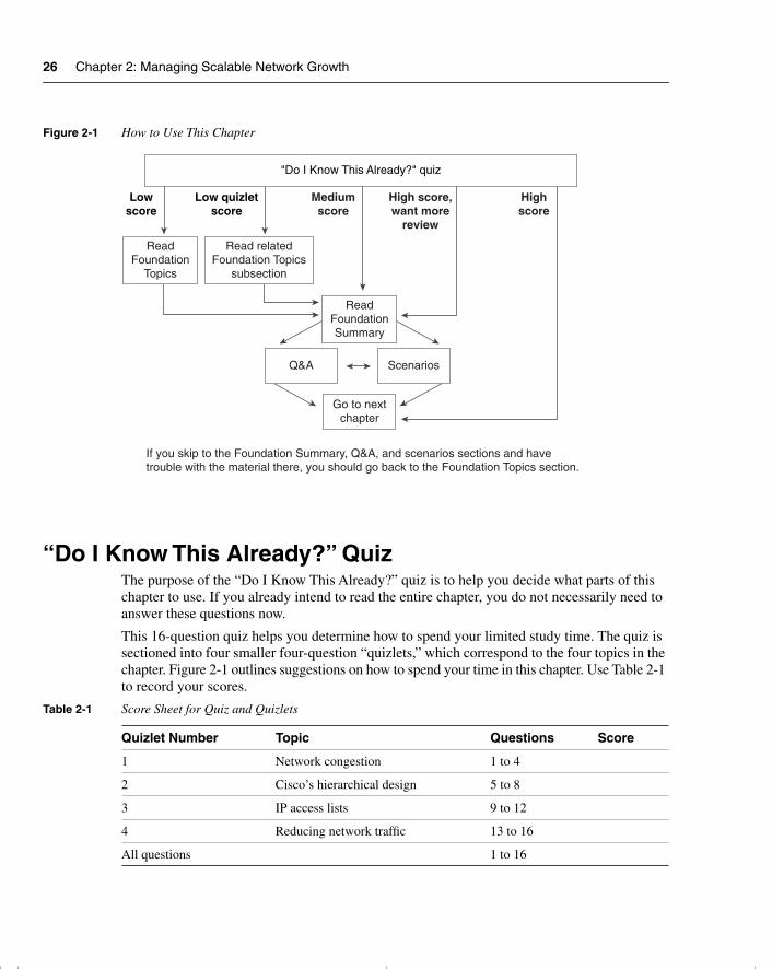
26 Chapter 2: Managing Scalable Network Growth
Figure 2-1 How to Use This Chapter
“Do I Know This Already?” QuizThe purpose of the “Do I Know This Already?” quiz is to help you decide what parts of this chapter to use. If you already intend to read the entire chapter, you do not necessarily need to answer these questions now.
This 16-question quiz helps you determine how to spend your limited study time. The quiz is sectioned into four smaller four-question “quizlets,” which correspond to the four topics in the chapter. Figure 2-1 outlines suggestions on how to spend your time in this chapter. Use Table 2-1 to record your scores.
Table 2-1 Score Sheet for Quiz and Quizlets
Quizlet Number Topic Questions Score
1 Network congestion 1 to 4
2 Cisco’s hierarchical design 5 to 8
3 IP access lists 9 to 12
4 Reducing network traffic 13 to 16
All questions 1 to 16
Lowscore
Low quizletscore
Mediumscore
High score,want more
review
Highscore
"Do I Know This Already?" quiz
ReadFoundation
Topics
Read relatedFoundation Topics
subsection
ReadFoundationSummary
Q&A Scenarios
Go to nextchapter
If you skip to the Foundation Summary, Q&A, and scenarios sections and havetrouble with the material there, you should go back to the Foundation Topics section.
chpt_01.book Page 26 Thursday, December 21, 2000 6:22 PM
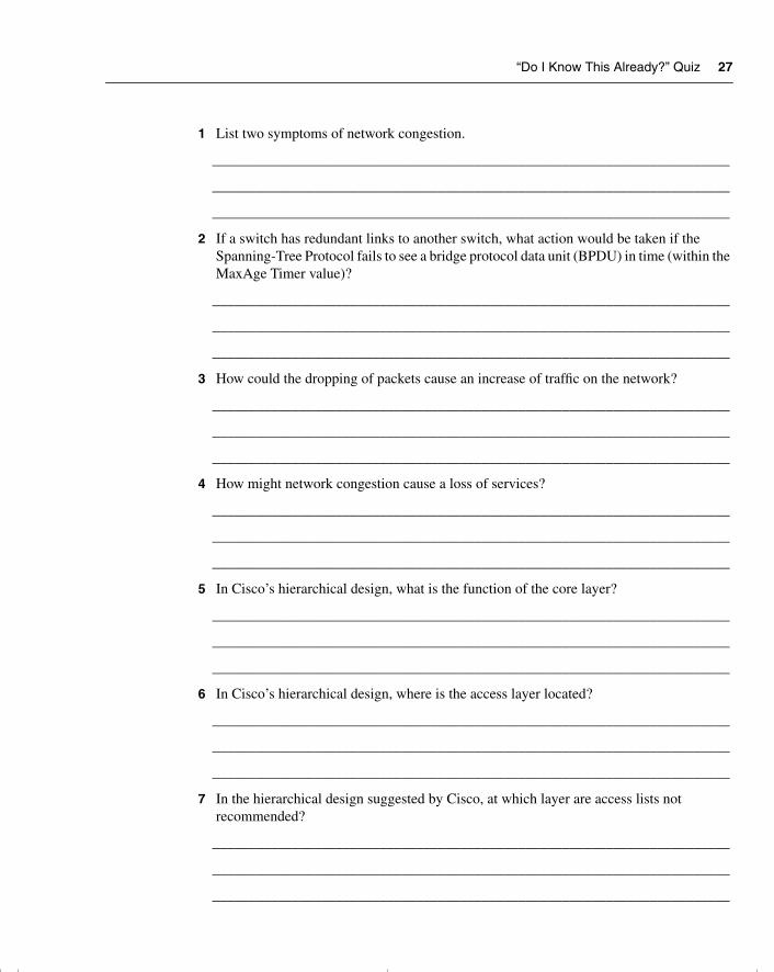
“Do I Know This Already?” Quiz 27
1 List two symptoms of network congestion.
_______________________________________________________________________
_______________________________________________________________________
_______________________________________________________________________
2 If a switch has redundant links to another switch, what action would be taken if the Spanning-Tree Protocol fails to see a bridge protocol data unit (BPDU) in time (within the MaxAge Timer value)?
_______________________________________________________________________
_______________________________________________________________________
_______________________________________________________________________
3 How could the dropping of packets cause an increase of traffic on the network?
_______________________________________________________________________
_______________________________________________________________________
_______________________________________________________________________
4 How might network congestion cause a loss of services?
_______________________________________________________________________
_______________________________________________________________________
_______________________________________________________________________
5 In Cisco’s hierarchical design, what is the function of the core layer?
_______________________________________________________________________
_______________________________________________________________________
_______________________________________________________________________
6 In Cisco’s hierarchical design, where is the access layer located?
_______________________________________________________________________
_______________________________________________________________________
_______________________________________________________________________
7 In the hierarchical design suggested by Cisco, at which layer are access lists not recommended?
_______________________________________________________________________
_______________________________________________________________________
_______________________________________________________________________
chpt_01.book Page 27 Thursday, December 21, 2000 6:22 PM
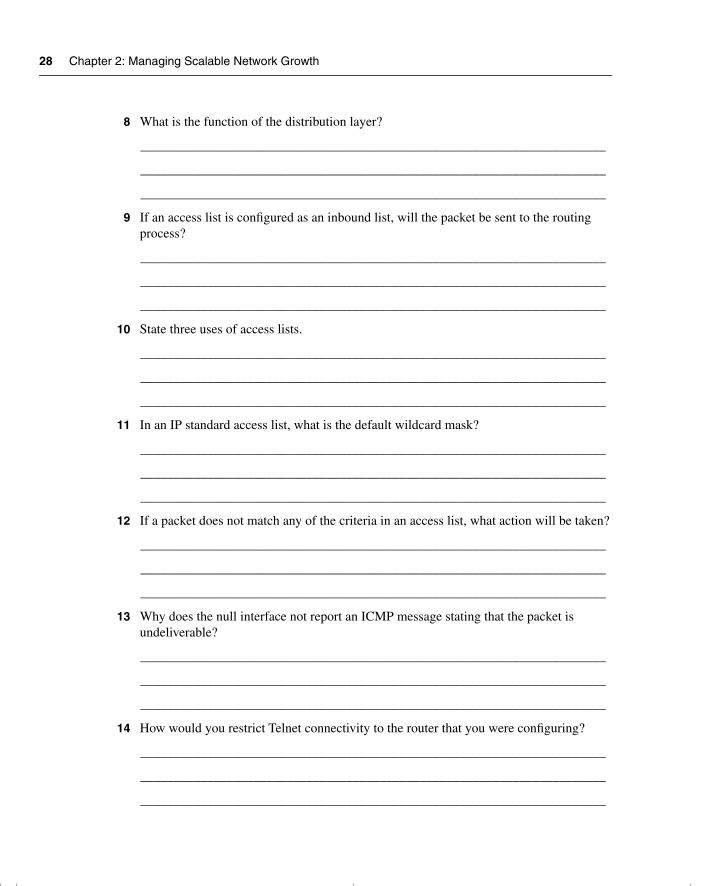
28 Chapter 2: Managing Scalable Network Growth
8 What is the function of the distribution layer?
______________________________________________________________________
______________________________________________________________________
______________________________________________________________________
9 If an access list is configured as an inbound list, will the packet be sent to the routing process?
______________________________________________________________________
______________________________________________________________________
______________________________________________________________________
10 State three uses of access lists.
______________________________________________________________________
______________________________________________________________________
______________________________________________________________________
11 In an IP standard access list, what is the default wildcard mask?
______________________________________________________________________
______________________________________________________________________
______________________________________________________________________
12 If a packet does not match any of the criteria in an access list, what action will be taken?
______________________________________________________________________
______________________________________________________________________
______________________________________________________________________
13 Why does the null interface not report an ICMP message stating that the packet is undeliverable?
______________________________________________________________________
______________________________________________________________________
______________________________________________________________________
14 How would you restrict Telnet connectivity to the router that you were configuring?
______________________________________________________________________
______________________________________________________________________
______________________________________________________________________
chpt_01.book Page 28 Thursday, December 21, 2000 6:22 PM
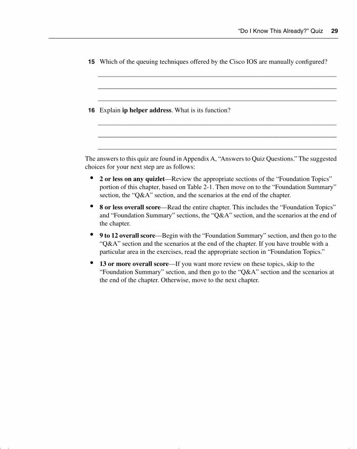
“Do I Know This Already?” Quiz 29
15 Which of the queuing techniques offered by the Cisco IOS are manually configured?
_______________________________________________________________________
_______________________________________________________________________
_______________________________________________________________________
16 Explain ip helper address. What is its function?
_______________________________________________________________________
_______________________________________________________________________
_______________________________________________________________________
The answers to this quiz are found in Appendix A, “Answers to Quiz Questions.” The suggested choices for your next step are as follows:
• 2 or less on any quizlet—Review the appropriate sections of the “Foundation Topics” portion of this chapter, based on Table 2-1. Then move on to the “Foundation Summary” section, the “Q&A” section, and the scenarios at the end of the chapter.
• 8 or less overall score—Read the entire chapter. This includes the “Foundation Topics” and “Foundation Summary” sections, the “Q&A” section, and the scenarios at the end of the chapter.
• 9 to 12 overall score—Begin with the “Foundation Summary” section, and then go to the “Q&A” section and the scenarios at the end of the chapter. If you have trouble with a particular area in the exercises, read the appropriate section in “Foundation Topics.”
• 13 or more overall score—If you want more review on these topics, skip to the “Foundation Summary” section, and then go to the “Q&A” section and the scenarios at the end of the chapter. Otherwise, move to the next chapter.
chpt_01.book Page 29 Thursday, December 21, 2000 6:22 PM
30 Chapter 2: Managing Scalable Network Growth
Foundation Topics
Introduction to Corporate Networks—Growth, Scalability, and Congestion
NOTE Each chapter begins with a case study. The case study provides context for the topics dealt with in the chapter. The case study may be referred to throughout the chapter in an effort to further explain the technology, and the case study will also sometimes be revisited in the “Scenarios” section at the end of the chapter.
Use the case study to focus your attention. In this way, you will learn the details more easily as you solve the problem presented at the beginning of the chapter. The concrete framework that the case studies provide should help you retain the theories throughout each chapter.
The company Pedopodgy, which is a private college, realized the need to network the central administrative offices five years ago. The initial network comprised of 45 PCs, 5 print servers, and 1 file server. It was a NetWare network, running IP. The administration at each of the five campuses was added two years later. Last year, the company provided Internet access for each student, with Internet connectivity accessed through corporate headquarters.
The network has grown considerably in the last five years. This growth has been in both end nodes and complexity. In end nodes alone, the network has grown from 45 PCs, with the 5 print servers and 1 file server, to more than 500 PCs connecting to 30 print servers and 20 file servers.
Everyone is complaining. The network is unreliable, unresponsive, and difficult to use, and there have been several security break-ins. The main problem is that the network has exceeded its original design, and the infrastructure of the network can no longer handle the volume of traffic generated. The IT department is being besieged by angry users.
This type of story is very familiar. Every network consultant has heard a variation of it a thousand times, and you can hear versions in conversations on the bus, the train, or the ferry.
This chapter addresses the problems seen in this case study. It identifies the key requirements of a network and illustrates how a structured design can simplify and help in the management of the network. This chapter also explains how excessive traffic on the network can thwart user needs and shows some of the ways that network traffic can be alleviated.
In designing a network, it is important to identify the key requirements of the network. Although any network will have the same core requirements, the business needs of a specific organization can elevate a particular network requirement above another.
chpt_01.book Page 30 Thursday, December 21, 2000 6:22 PM
Key Requirements of a Network 31
As seen in the case study, a network that is inadequate to the needs of its users does not only frustrate the user base, but it also affects the organization’s capability to function.
Key Requirements of a NetworkWhen designing a network, you first must define and assess customer requirements and then put together a plan to meet these requirements. Therefore, an understanding of the business structure and current data flow within the existing environment is crucial to prioritizing the requirements of the network. The relative importance of each of the following broad key requirement categories is determined by the needs of the organization in question. For example, a small, growing catering company may place more importance on efficiency, adaptability, and accessibility than a large financial institution that demands reliability, responsiveness, and security. The college cited in the case study would require the network to be secure as well as reliable and responsive.
The sections that follow describe the key requirements of a network:
• Reliability
• Responsiveness
• Efficiency
• Adaptability/serviceability
• Accessibility/security
• Factors that increase network traffic
ReliabilityFor a hospital or bank, the network must be available 24 hours a day, seven days a week. In the first instance, lives are at stake. If network access cannot be granted to the blood bank, it may not be possible to give a life-saving transfusion. For a bank exchanging money throughout international markets across every time zone, a network fault can be extremely expensive. In such a situation, network downtime can cost millions of dollars per fraction of an hour. The capability to isolate and limit any problems that occur, therefore, is as important as solving the problem quickly.
ResponsivenessExcessive latency within a network appears to the end user as a lack of responsiveness. Frustration sets in and often leads the user to reboot or to repeat keystrokes. This response is the same one that might cause you to raise your voice to someone who does not answer your question; you assume that the person hasn’t heard the question. In the network environment,
chpt_01.book Page 31 Thursday, December 21, 2000 6:22 PM
32 Chapter 2: Managing Scalable Network Growth
however, repeating keystrokes generates more network traffic, which increases congestion and delays. Avoiding this is essential for network health. To do so, build in mechanisms to alleviate congestion and to prioritize certain protocols that are more sensitive to delay.
EfficiencyDesigning a network that restricts traffic to allow only the necessary information to be carried across it proves extremely helpful in preventing congestion. The inefficiency in allowing network and service updates to travel to areas of your network that have no need for the information can seriously limit the available bandwidth left for data. For example, allowing users in Brussels, Belgium, to see printers in Palo Alto, California, is not very helpful and may saturate the 56-kbps serial link.
Adaptability/ServiceabilityIt is difficult to anticipate every change that your company may make in terms of mergers and organizational structure. Therefore, building an adaptable network protects capital investment. It also increases the reliability of the network. Because network administrators are not issued crystal balls, it is essential that attention be given to the interoperability of both products and applications when designing the network. Thus, when the company makes a business change, network changes may be needed. Imagine that Pedopodgy has recently acquired a marketing manager, who has bought five Macintoshes for his department, running graphic production software. The infrastructure of the network need to be considered in terms of not only the additional bandwidth requirements, but also the capability to share files. In short, the nature of the client/server interaction on the rest of the network should be determined.
Serviceability is related to adaptability, but it is more focused toward being able to make changes to production systems without disrupting normal operations (for example, hot redundancy and dual power supplies).
Accessibility/SecuritySecurity is a popular topic and a major consideration, particularly as more companies connect to the Internet and thereby increase the chance of hackers, idly wandering into the network. Weighing the needs of users to access the network, particularly when remote access is required, against the need to secure company secrets is a difficult balance that requires careful consideration at the executive level. It is important to consider security as part of the initial design because it is very difficult to address this issue as an afterthought. In the case of the Pedopodgy case study, the security of student grades as well as tests that may be stored electronically is important.
chpt_01.book Page 32 Thursday, December 21, 2000 6:22 PM
Identifying the Problems Created by Network Congestion 33
Although this book identifies the main requirements of a network, only a few of these are examined in depth in the CCNP/CCDP Routing exam. One of the areas addressed in the exam is that of network congestion and the methods to alleviate it in an IP network.
Factors That Increase Network TrafficIt cannot be denied that company networks are growing at a dramatic rate. When designing a network, the challenge is to create a system that will grow with the company and be capable of dealing with increased demand. Obviously, the size, nature, and maturity of the business will affect the demand for increased network resources.
Networking is still young and has only very recently extended to the home and small business. Therefore, it is a safe assumption that networks and the demand for network traffic will continue to grow for some time. As seen in the case study at the beginning of the chapter, this can cause problems.
In addition to the increase in the number of users, applications have become more complex, evolving into highly graphic and often interactive packages.
If the design and implementation of the original network has been well managed, network growth increases dramatically within the first year. Networks must therefore adapt to change to allow growth. As an analogy, instead of constantly buying new clothes for the sprouting child, we can just let down hems and lengthen sleeves. Companies cannot afford either the capital investment or the hours involved in accommodating a network that must be redesigned frequently. The consequence of having a network incapable of scaling is that as it grows it becomes constricted, just like the child squeezed into a coat that is too small. The result within your company would be network congestion.
Identifying the Problems Created by Network Congestion
Network congestion results when too many packets are competing for limited bandwidth. The result is similar to that of heavy road traffic: collisions, delays, and user frustration.
Traffic Analysis and Network DesignThe problems caused by network congestion are easily identified. By using network-monitoring tools, such as Cisco’s TrafficDirector or a standard protocol analyzer, it is possible to ascertain the traffic volume either on an entire network or on individual segments. An understanding of the traffic volumes within the network can also be gained by issuing commands at the Cisco router. Commands such as show interface, show buffers, and show queuing can give a feel for the traffic levels within the network, without purchasing extra products. It is important to understand the context of the traffic flow within your network so that you can appropriately
chpt_01.book Page 33 Thursday, December 21, 2000 6:22 PM
34 Chapter 2: Managing Scalable Network Growth
accommodate the requirements of the users and their applications, designing and building a network that will scale.
The traffic on the network typically follows the organization’s business flow, responding not only to peaks and valleys in business cycles, but also to the direction of the traffic flow as well. Necessarily, the communication between the accounting department and the marketing department within the organization will reflect the network traffic. The appropriate placement of network resources, such as servers, can be considered after the organizational flow of data has been identified. The network and the placement of the servers dictate the traffic flow throughout the company. Poor design inevitably leads to congestion.
Problems Created by Network CongestionThe next sections cover the following problems created by network congestion:
• Excessive traffic
• Dropped packets
• Retransmission of packets
• Incomplete routing tables
• Incomplete server lists
• The Spanning-Tree Protocol breaks
• Runaway congestion
Excessive TrafficIf the traffic volume outgrows the network, the result is congestion. When this occurs on a single segment, the capacity of the medium overrun—resulting in the dropping of packets—and the medium can react adversely to excessive traffic.
Physical Problems of EthernetEthernet illustrates this well. Ethernet has strict rules about accessing the medium, so, a physical problem—such as extraneous noise or just too many trying to access too little—results in excessive traffic, causing collisions. A collision requires all transmitting devices to stop sending data and to wait a random amount of time before attempting to send the original packet. Only the nodes involved in the collision are required to wait during the backoff period. Other nodes must wait until the end of the jam signal and the interframe gap (9.6 ms for Ethernet, 0.96 ms for Fast Ethernet, and 0.096 ms for Gigabit Ethernet). If after 16 attempts the device fails to transmit, it gives up and reports the error to the calling process. If for this or any other reason the device fails to transmit and drops the packet from its buffer, the application typically
chpt_01.book Page 34 Thursday, December 21, 2000 6:22 PM
Identifying the Problems Created by Network Congestion 35
retransmits the original packet. This may result in increased congestion that grows exponentially, which is often referred to as runaway congestion.
Dropped PacketsOne of the effects of congestion is that not all the packets can get through the network. Essentially, the queues and buffers in the intermediate forwarding devices (for example, routers) overflow and must drop packets, causing an OSI higher-layer process on either end device (for example, workstation) to time out. Typically, the transport or application layers have the responsibility to ensure the arrival of every piece of data.
Maintaining the integrity of the transmission requires the communication to be connection-oriented, giving the end devices the mechanisms to perform error detection and correction (for example, the TCP layer of TCP/IP) through windowing, sequencing, and acknowledgments.
Retransmission of PacketsIf packets are dropped, the layer responsible for the integrity of the transmission will retransmit the lost packets. If the session or application layer does not receive the packets that were resent in time, the result will be either incomplete information or timeouts.
Incomplete Routing TablesThe application may be unaware that it did not receive all the data; this missing data may just appear as an error or may have more subtle and insidious effects. For example, if the routing table of an intermediate forwarding device such as a router is incomplete, it may make inaccurate forwarding decisions, resulting in loss of connectivity or even the dreaded routing loop (see Figure 2-2).
Using the case study earlier in this chapter, if the WAN connection between the campus site and the corporate headquarters becomes congested, packets may be dropped, possibly resulting in the receipt of partial routing updates. In Figure 2-2, for example, if Router X hears a full update, the routing table will know subnetworks 10, 20, and 30. Imagine that Router Y does not receive a full update from Router X. It knows only about subnetworks 20 and 30. When Workstation A tries to connect to Server B at the corporate offices, it has a problem. Router X can direct the traffic to Router Y. In turn, Router Y can forward traffic to Server B.
However, when Server B responds, Router Y has no way to forward back to Router X because it has no entry for remote subnetwork 10. In a more complex environment, routing loops often occur because of poor network design.
chpt_01.book Page 35 Thursday, December 21, 2000 6:22 PM
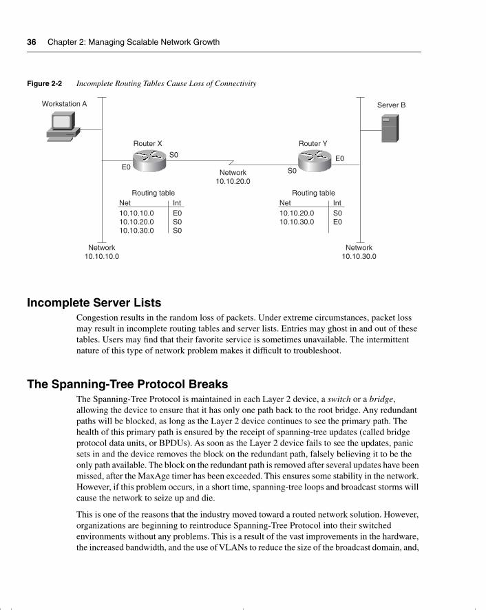
36 Chapter 2: Managing Scalable Network Growth
Figure 2-2 Incomplete Routing Tables Cause Loss of Connectivity
Incomplete Server ListsCongestion results in the random loss of packets. Under extreme circumstances, packet loss may result in incomplete routing tables and server lists. Entries may ghost in and out of these tables. Users may find that their favorite service is sometimes unavailable. The intermittent nature of this type of network problem makes it difficult to troubleshoot.
The Spanning-Tree Protocol BreaksThe Spanning-Tree Protocol is maintained in each Layer 2 device, a switch or a bridge, allowing the device to ensure that it has only one path back to the root bridge. Any redundant paths will be blocked, as long as the Layer 2 device continues to see the primary path. The health of this primary path is ensured by the receipt of spanning-tree updates (called bridge protocol data units, or BPDUs). As soon as the Layer 2 device fails to see the updates, panic sets in and the device removes the block on the redundant path, falsely believing it to be the only path available. The block on the redundant path is removed after several updates have been missed, after the MaxAge timer has been exceeded. This ensures some stability in the network. However, if this problem occurs, in a short time, spanning-tree loops and broadcast storms will cause the network to seize up and die.
This is one of the reasons that the industry moved toward a routed network solution. However, organizations are beginning to reintroduce Spanning-Tree Protocol into their switched environments without any problems. This is a result of the vast improvements in the hardware, the increased bandwidth, and the use of VLANs to reduce the size of the broadcast domain, and,
Workstation A
Router X Router Y
Server B
Network10.10.10.0
Network10.10.20.0
Network10.10.30.0
Routing tableNet Int10.10.10.010.10.20.010.10.30.0
E0S0S0
Routing tableNet Int10.10.20.010.10.30.0
S0E0
E0E0S0
S0
chpt_01.book Page 36 Thursday, December 21, 2000 6:22 PM
Symptoms of Congestion 37
in a Cisco implementation, the spanning-tree domain. Another factor that positively affects the stability of large flat networks is the increasing use of multicast addresses. Multicast addresses are read only by devices belonging to the multicast address and are forwarded only to segments that contain such devices. Refer to the Cisco Design Guides, on the Cisco Connection Online (CCO) web page, for more information on these topics.
Runaway CongestionWhen packets are dropped, requiring retransmission, the congestion will inevitably increase. In some instances, this may increase the traffic exponentially; this is often called runaway congestion. In relatively unsophisticated protocols, such as Spanning-Tree Protocol, it is almost unavoidable, although others may have methods of tracking the delays in the network and throttling back on transmission. Both TCP and AppleTalk’s DDP use flow control to prevent runaway congestion. Therefore, it is important to understand the nature of the traffic on your network when designing scalable networks.
Symptoms of CongestionThe symptoms of congestion are intermittent, and the following problems may be due not to congestion but to some underlying problem within the network. This is another reason why problems that result from congestion are so difficult to diagnose.
The following example shows why congestion problems are difficult to identify. If the link is running near bandwidth capacity and the connected devices are overwhelmed, any additional traffic will cause problems. Because the packets are randomly dropped, it is difficult to track where the problems have occurred. Therefore, the network will have equally random failures. The symptoms of network congestion are consequently difficult to troubleshoot because some protocols are more sensitive than others and will time out after very short delays are experienced. However, the network administrator who knows his network well will soon identify these recurring problems. The following are three symptoms of network congestion:
• Applications time out.
• Clients cannot connect to network resources.
• Network death results.
NOTE Packets are randomly dropped only if there is not quality of service (QoS) configured within the network.
chpt_01.book Page 37 Thursday, December 21, 2000 6:22 PM
38 Chapter 2: Managing Scalable Network Growth
Applications Time OutThe session layer of the OSI model is responsible for maintaining the communication flow between the two end devices. This includes assigning resources to incoming requests to connect to an application. To allocate resources adequately, idle timers disconnect sessions after a set time, releasing those resources for other requests. Note that although the OSI model assigns these duties to the session layer, many protocol stacks include the upper layers of the stack in the application. TCP/IP is such a protocol.
Clients Cannot Connect to Network ResourcesThe client/server environment is one in which applications take advantage of networks. Servers provide services to many clients that access them across the network. Both data and application software may be stored centrally on a server that allows many clients to share them. If all users depend on the client/server interaction, this can create excessive traffic across the network.
In a client/server environment, the available resources are communicated throughout the network. The dynamic nature of the resource tables (offering services, servers, or networks) gives an up-to-date and accurate picture of the network. NetWare, AppleTalk, Vines, and Windows NT all work on this principle. If these tables are inaccurate as a result of the loss of packets in your network, errors will be introduced because decisions were made with incorrect information. Some network systems are moving more toward a peer-to-peer system in which the end user requests a service identified not by the network, but by the administrator.
Network Death ResultsThe most common problems arising from network congestion are intermittent connectivity and excessive delays—users must wait a long time for screens to refresh, users are disconnected from applications, print jobs fail, and errors result when trying to write files to remote servers. If the response of the applications is to retransmit, congestion could reach a point of no recovery. Likewise, if routing or spanning-tree loops are introduced as a result of packet loss, the excessive looping traffic could bring your network down.
Creating a Network That Meets the Key Requirements
Although is important to know how to reduce network congestion when it occurs, it is crucial to build a network that can grow with the user needs, thus preventing a network that reels from crisis to crisis. Designing the network so that it can scale, therefore, is crucial. Cisco provides a hierarchical design that should simplify network management and also allow the network to grow. This growth may be a physical growth as well as a capacity growth.
chpt_01.book Page 38 Thursday, December 21, 2000 6:22 PM
Creating a Network That Meets the Key Requirements 39
Cisco’s Hierarchical DesignTo achieve these networks requirements that have been described—and to keep local traffic local, preventing network congestion—Cisco suggests a network design structure that allows for growth. The key to the design is that it is hierarchical. There is a division of functionality between the layers of the hierarchy, allowing only certain traffic —based on clear criteria—to be forwarded through to the upper levels. A filtering operation restricts unnecessary traffic from traversing the network. Thus, the network is more adaptable, scalable, and more reliable. Clear guidelines and rules govern how to design networks according to these principles. These guidelines and rules are covered in the Cisco design class as well as design guides provided by Cisco on its web page. The following section explains how the hierarchical network design proposed by Cisco reduces congestion.
Why Scaling Reduces CongestionIf the network is designed hierarchically, with each layer acting as a filter to the layer beneath it, the network can grow effectively. In this way, local traffic is kept local, and only data and information about global resources needs to travel outside the immediate domain.
Understanding that the layers are filtering layers begs the question of how many layers are required in your network. The answer is, it depends on the type of applications and network architecture, to name but a few criteria.
How Hierarchical Is Hierarchical?Cisco’s design methodology is based on simplicity and filtering. Cisco suggests that the largest networks currently require no more than three layers of filtering.
Because a hierarchical layer in the network topology is a control point for traffic flow, a hierarchical layer is the same as a routing layer. Thus, a layer of hierarchy is created with the placement of a router or, more recently, a Layer 3 switching device.
The number of hierarchical layers that you need to implement in your network reflects the amount of traffic control required. To determine how many layers are required, you must identify the function that each layer will have within your network.
The Functions of Each LayerEach hierarchical layer in the network design is responsible for preventing unnecessary traffic from being forwarded to the higher layers (and then being discarded at a higher point in the network or by the receiving stations). The goal is to allow only relevant traffic to traverse the network and thereby reduce the load on the network. If this goal is met, the network can scale more effectively. The three layers of a hierarchy are as follows:
• The access layer
chpt_01.book Page 39 Thursday, December 21, 2000 6:22 PM
40 Chapter 2: Managing Scalable Network Growth
• The distribution layer
• The core layer
The Access LayerIn accordance with its name, the access layer is where the end devices connect to the network—where they gain access to the company network. The Layer 3 devices (such as routers) that guard the entry and exit to this layer are responsible for ensuring that all local server traffic does not leak out to the wider network. QoS classification is performed here along with other technologies that define the traffic that is to traverse the network. Service Advertisement Protocol (SAP) filters for NetWare and AppleTalk’s GetZoneLists are implemented here, in reference to the design consideration of client/server connectivity.
The Distribution LayerThe distribution layer is responsible for determining access across the campus backbone by filtering out unnecessary resource updates and by selectively granting specific access to users and departments. Access lists are used not just as traffic filters, but as the first level of rudimentary security.
Access to the Internet is implemented here, requiring a more sophisticated security or firewall system.
The Core LayerThe responsibility of the core layer is to connect the entire enterprise. At the pinnacle of the network, reliability is of the utmost importance. A break in the network at this level would result in the incapability of large sections of the organization to communicate. To ensure continuous connectivity, the core layer should be designed to be highly redundant, and, as much as possible, all latency should be removed. Because latency is created when decisions are required, decisions relating to complex routing decisions, such as filters, should not be implemented at this layer. They should be implemented at the access or distribution layers, leaving the core layer with the simple duty of relaying the data as fast as possible to the remote site. In some implementations, QoS is implemented at this layer to ensure a higher priority to certain packets to prevent them from being lost during high congestion periods.
General Design Rules for Each LayerA clear understanding of the traffic patterns within the organization—who is connecting to whom and when—helps to ensure the appropriate placement of client and servers, and eases the implementation of filtering at each layer. The filtering that is imposed by the router creates the network hierarchy illustrated in Figure 2-3. Without hierarchy, networks have less capacity to
chpt_01.book Page 40 Thursday, December 21, 2000 6:22 PM
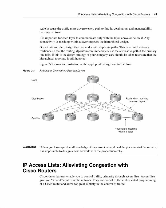
IP Access Lists: Alleviating Congestion with Cisco Routers 41
scale because the traffic must traverse every path to find its destination, and manageability becomes an issue.
It is important for each layer to communicate only with the layer above or below it. Any connectivity or meshing within a layer impedes the hierarchical design.
Organizations often design their networks with duplicate paths. This is to build network resilience so that the routing algorithm can immediately use the alternative path if the primary line fails. If this is the design strategy of your company, care should be taken to ensure that the hierarchical topology is still honored.
Figure 2-3 shows an illustration of the appropriate design and traffic flow.
Figure 2-3 Redundant Connections Between Layers
WARNING Unless you have a profound knowledge of the current network and the placement of the servers, it is impossible to design a new network with the proper hierarchy.
IP Access Lists: Alleviating Congestion with Cisco Routers
Cisco router features enable you to control traffic, primarily through access lists. Access lists give you “what if” control of the network. They are crucial to the sophisticated programming of a Cisco router and allow for great subtlety in the control of traffic.
Redundant meshingwithin a layer
Redundant meshingbetween layers
Core
Distribution
Access
chpt_01.book Page 41 Thursday, December 21, 2000 6:22 PM
42 Chapter 2: Managing Scalable Network Growth
Given that the router operates at Layer 3, the control that is offered is extensive. The router can also act at higher layers of the OSI model. This proves useful when identifying particular traffic and protocol types for prioritization across slower WAN links.
Cisco Proprietary SolutionsWith the assumption that connections are between Cisco routers, Cisco has optimized many network operations. This sometimes requires a proprietary solution. While defying some of the standards to streamline network traffic, Cisco has been conscientious by providing both the standard solution and a proprietary Cisco solution. To ensure the capability to integrate Cisco equipment into all networks, Cisco offers sophisticated methods of translation between the standard and the proprietary Cisco solution. The clearest example of this is the use of redistribution between Cisco’s routing protocol, Enhanced Interior Gateway Routing Protocol (EIGRP), and any other routing protocol such as Open Shortest Path First (OSPF).
Managing Network Congestion for IPIP is generally considered a well-behaved protocol because its communication is typically peer-to-peer, removing the necessity for excessive broadcasts throughout the network. The only broadcasts are routing updates and Address Resolution Protocol (ARP) requests. These characteristics can no longer be assumed, however, as client/server technologies start to offer IP as a communication protocol. It should be understood that the application demands determine the nature of the traffic on the network. Therefore, if the application relies on broadcasts to locate its server, the protocol used to communicate that broadcast is of little concern. The routed protocols AppleTalk and IPX, and the nonrouted protocol NetBIOS are the obvious examples of protocols used by client/server applications. These protocols were designed for LAN networks and tend to be very chatty in the communication between the client and the server. Recently these network protocols have utilized TCP/IP as the transport method, but the client/server communication is still based on a broadcast technology that defies the peer-to-peer architecture of TCP/IP and renders it chatty.
It would be misleading to suggest that improvements in network utilization have not been made by these protocols, which were originally designed for small LAN environments instead of the enterprise solutions for which they are now being sold. Nevertheless, it is important to emphasize the need to do careful analysis of the network traffic flow and to understand the communication requirements between the client and the server.
The Implementation of IP Access ListsAccess lists can be used to either restrict or police traffic entering or leaving a specified interface. They are also used to implement “what if” logic on a Cisco router. This gives you the only real mechanism of programming the Cisco router. The access lists used for IP in this way
chpt_01.book Page 42 Thursday, December 21, 2000 6:22 PM
IP Access Lists: Alleviating Congestion with Cisco Routers 43
enable you to apply great subtlety in the router’s configuration. This chapter reviews how to configure access lists and discusses their use in an IP network. The Interconnecting Cisco Network Devices coursebook and the Cisco CCNA Exam #640-507 Certification Guide, both from Cisco Press, deal with these subjects in more depth.
IP Access List OverviewAccess lists are linked lists with a top-down logic, ending in an implicit deny any command, which will deny everything. Top-down logic means that the process will read from the top of the access list and stop as soon as it meets the first entry in the list that matches the packet’s characteristics. Therefore, it is crucial that careful attention be given to their creation. Writing down the purpose of the proposed access list before attempting to program the system also proves helpful.
Access lists block traffic traversing the router. Remember that traffic generated by the router is not blocked by an access list.
Standard IP Access ListsThe following is syntax for a standard access-list command and an ip access-group command:
access-list access-list-number {permit | deny}{source [source-wildcard | any]}ip access-group access-list-number {in | out}
Note that the access-list-number value must be within the range of 1 to 99 to create a standard access list.
Standard access lists are implemented at Layer 3. In general, both the source and destination addresses are identified as criteria in the logic of the list. IP access lists work slightly differently, however; they use the source address only.
The placement of the access list is crucial because it may determine the effectiveness of the control imposed. Because the decision to forward can be made on the source address only, the access list is placed as close to the destination as possible (to allow connectivity to intermediary devices).
For example, in Figure 2-4, the intention of the access list is to prevent the library terminals access to the administrative LAN in the college Pedopodgy. The reasoning in placing the access list so close to the source is to increase security and reduce traffic. In fact, all traffic from network 10.10.10.0 is denied access to the rest of the network, so Figure 2-4 shows incorrect access list placement.
chpt_01.book Page 43 Thursday, December 21, 2000 6:22 PM
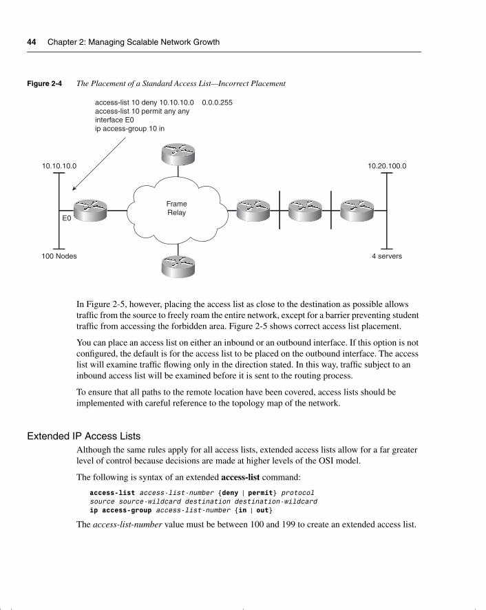
44 Chapter 2: Managing Scalable Network Growth
Figure 2-4 The Placement of a Standard Access List—Incorrect Placement
In Figure 2-5, however, placing the access list as close to the destination as possible allows traffic from the source to freely roam the entire network, except for a barrier preventing student traffic from accessing the forbidden area. Figure 2-5 shows correct access list placement.
You can place an access list on either an inbound or an outbound interface. If this option is not configured, the default is for the access list to be placed on the outbound interface. The access list will examine traffic flowing only in the direction stated. In this way, traffic subject to an inbound access list will be examined before it is sent to the routing process.
To ensure that all paths to the remote location have been covered, access lists should be implemented with careful reference to the topology map of the network.
Extended IP Access ListsAlthough the same rules apply for all access lists, extended access lists allow for a far greater level of control because decisions are made at higher levels of the OSI model.
The following is syntax of an extended access-list command:
access-list access-list-number {deny | permit} protocol source source-wildcard destination destination-wildcardip access-group access-list-number {in | out}
The access-list-number value must be between 100 and 199 to create an extended access list.
10.10.10.0
100 Nodes
10.20.100.0
4 servers
E0
access-list 10 deny 10.10.10.0 0.0.0.255access-list 10 permit any anyinterface E0ip access-group 10 in
FrameRelay
chpt_01.book Page 44 Thursday, December 21, 2000 6:22 PM
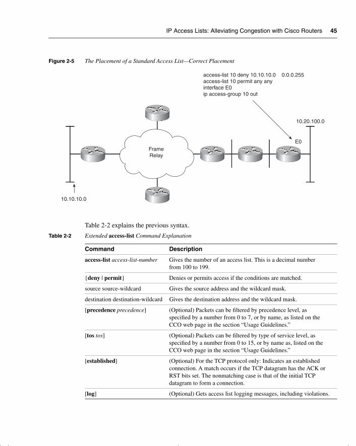
IP Access Lists: Alleviating Congestion with Cisco Routers 45
Figure 2-5 The Placement of a Standard Access List—Correct Placement
Table 2-2 explains the previous syntax.
Table 2-2 Extended access-list Command Explanation
Command Description
access-list access-list-number Gives the number of an access list. This is a decimal number from 100 to 199.
{deny | permit} Denies or permits access if the conditions are matched.
source source-wildcard Gives the source address and the wildcard mask.
destination destination-wildcard Gives the destination address and the wildcard mask.
[precedence precedence] (Optional) Packets can be filtered by precedence level, as specified by a number from 0 to 7, or by name, as listed on the CCO web page in the section “Usage Guidelines.”
[tos tos] (Optional) Packets can be filtered by type of service level, as specified by a number from 0 to 15, or by name as, listed on the CCO web page in the section “Usage Guidelines.”
[established] (Optional) For the TCP protocol only: Indicates an established connection. A match occurs if the TCP datagram has the ACK or RST bits set. The nonmatching case is that of the initial TCP datagram to form a connection.
[log] (Optional) Gets access list logging messages, including violations.
10.10.10.0
10.20.100.0
E0
access-list 10 deny 10.10.10.0 0.0.0.255access-list 10 permit any anyinterface E0ip access-group 10 out
FrameRelay
chpt_01.book Page 45 Thursday, December 21, 2000 6:22 PM
46 Chapter 2: Managing Scalable Network Growth
In recent versions of the IOS, many additional options have been given to the creation of the access lists. These include the use of named access lists, as well as the capability to set timeouts on the access lists. This is outside the scope of this exam and, therefore, also the exam guide. For further details, refer to the Cisco CCO web pages for the “Managing the System” chapter in the Configuration Fundamentals Configuration Guide.
WARNING When using extended access lists to prevent application connection, it is easy to become confused. TCP and UDP are the common protocols and these include both an optional source port and an optional destination port. A common mistake is to specify stop telnet using a source port of 23 instead of a destination port of 23.
When using extended access lists, it is important to consider the sequence of conditions within the list. Because top-down logic is employed, the ordering of the list may alter the entire purpose of the list.
Guidelines for Writing Access ListsYou should adhere to the following guidelines when writing an access list:
• Write out the purpose to be achieved by the access list in clear, simple language.
• Determine the placement of the access list in reference to a topology map of the network.
• Write out the access list, ensuring that the following is considered:
1 The most frequent instance of traffic is placed first in the list, if possible, to reduce CPU processing.
2 Specific access is stated before group access is defined.
3 Group access is stated before world access is defined.
4 There is an implicit deny any at the end of the list.
5 The implicit deny statement in the access list means that there must be at least one permit statement, or the access list will deny everything.
6 If no wildcard mask has been defined in a standard access list, the mask of 0.0.0.0 is assumed. This mask would match every bit in the address. If the address was that of a subnet rather than an end station, no match would be found, and the router would move on to the next criteria line. If that line is the ending deny any, problems may occur.
7 The access list will not take effect until it has been applied to the interface. The access list will default to an outgoing access list if a direction is not specified.
chpt_01.book Page 46 Thursday, December 21, 2000 6:22 PM
IP Access Lists: Alleviating Congestion with Cisco Routers 47
WARNING Changes have been made to the way access lists function in terms of the deny any at the end of the access list. To avoid confusion, therefore, it is a good policy to read the documentation for your IOS version. To be safe, assume that everything will be denied by an implicit deny any at the end of the list because this will foster good practices.
• Test the access list with a utility such as ping. It is important to first ensure that the utility is permitted in the ACL. However, in more complex scenarios, ping may not suffice, and alternative methods should be used. Two common ways of doing this are to either use Telnet and modify the ports used, or, if possible, to obtain some type of port scanner and use only the specific ports allowed (as well as testing some that are not allowed).
• Use the show commands to verify the placement of the access list.
• If the access list needs to be modified, the list will have to be removed from the interface, deleted, and re-created as additional criteria is appended to the bottom of the list.
NOTE However, named access lists behave slightly differently. These are not in the scope of the course and should be researched well before they are implemented on a live network.
• It is useful to save the access list to a Trivial File Transfer Protocol (TFTP) server and just edit it offline.
WARNING Note that in some older versions of the IOS, deleting the access list at the global level without removing it from the interface may cause the interface to restrict all traffic through the interface in the direction that it was applied. This is because, although the access list is still applied to the interface, it has no content; therefore, the implicit deny any takes effect. Standard system management calls for making changes to the specific before moving back to the general—that is, removing the access group from a specific interface before deleting the global access list.
Verifying Filter ConfigurationWhenever a network is configured, that configuration must be tested, and the changes must be documented. Called maintaining the baseline, this enables you to maintain a clear knowledge of the network functionality.
The commands to verify the filter configuration for either IP or IPX filters are most easily accomplished through the show commands:
show access listshow ip interface
chpt_01.book Page 47 Thursday, December 21, 2000 6:22 PM
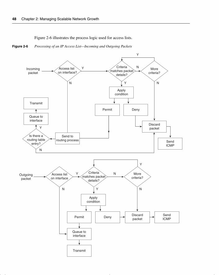
48 Chapter 2: Managing Scalable Network Growth
Figure 2-6 illustrates the process logic used for access lists.
Figure 2-6 Processing of an IP Access List—Incoming and Outgoing Packets
Incomingpacket
Y
Y
Y
Y
N N
N
N
Is there arouting table
entry?
Access liston interface
Criteriamatches packet
details?
Morecriteria?
Queue tointerface
Transmit
Access list on interface?
Send torouting process
Discardpacket
SendICMP
Applycondition
Permit Deny
Applycondition
Permit
Queue tointerface
Transmit
DenyDiscardpacket
SendICMP
Criteriamatches packet
details?
Morecriteria?
Outgoingpacket
N Y
NY
N
Y
chpt_01.book Page 48 Thursday, December 21, 2000 6:22 PM
Uses of IP Access Lists 49
Access lists are extremely powerful when you are configuring the router to tune the data flow through the device. Because access lists take both CPU and memory, however, you must consider alternatives. The following section discusses these alternatives.
NOTE Depending on the type of access list, the version of IOS, and the hardware configuration, some access lists are processed more quickly than others. This is because some access lists can be cached. For more information, refer to the configuration guides on the Cisco web page.
Uses of IP Access ListsBecause access lists can be used so subtly in system programming, they are used in many ways to solve many problems. IP access lists are used mainly to manage traffic.
Essentially, an access list is a list that uses a simple logic to decide whether to forward traffic. As such, access lists are sometimes used as a security system. Certain issues arise when using access lists for security purposes. The next section covers these in more detail.
Security Using Access ListsCisco recommends using alternative methods to access lists for security. Although access lists are complex to conceive and write, they are easy to spoof and break through. The 11.3 IOS has implemented full security features, and these sophisticated features should be utilized in preference to access lists. The Cisco Secure Integrated Software (IOS Firewall Feature Set) also is now available.
Some simple security tasks are well suited to access lists, however. Although access lists do not constitute complex security, they will deter the idle user exploring the company network.
The best way to use access lists for security is as the first hurdle in the system, to alleviate processing on the main firewall. Whether the processing on the firewall device is better designed for dealing with the whole security burden, or whether this task should be balanced between devices should be the topic of a capacity-planning project.
Controlling Terminal AccessAccess lists filter traffic traversing the router; they do not prevent traffic generated by the router. To control Telnet traffic in which the router is the end station, an access list can be placed on the virtual terminal line (vty).
Five terminal sessions are available: vty 0 through vty 4. Because anticipating which session will be assigned to which terminal is difficult, control is generally placed uniformly on all virtual terminals. Although this is the default configuration, some platforms have different limitations on the number of vty interfaces that can be created.
chpt_01.book Page 49 Thursday, December 21, 2000 6:22 PM
50 Chapter 2: Managing Scalable Network Growth
ConfigurationThe syntax for virtual terminal line commands is as follows:
line {vty-number | vty-range}access-class access-list-number {in | out}
Standard access lists are used for inbound access because the destination is known. The access-class command is the same as the access-group command but is used for terminal access. It could be applied as either an inbound or an outbound list. The access list used has the same structure as the standard access lists; even the range used in the command is the same, 1 through 99.
The following example of the configuration commands allow incoming Telnet access to the router only from hosts on network 131.99.55.0:
access-list 12 permit 131.99.55.0 0.0.0.255line vty 0 4access-class 12 in
When applied as an inbound access-class command to the vty, an access list restricts users from connecting to the router from the specified source addresses.
When applied as an outbound access-class command to the vty, an access list restricts users who have connected to the router and then attempt to connect to another system from that router. This is because the access list is still using the source address.
Other methods of restricting access are slightly more brutal. It is possible to issue the following command, for example:
no line vty 0 4
This command removes all terminal access.
It is also possible to issue the following commands:
line vty 0 4loginno password
This requires a password. Because a password has not been established, however, it is impossible to correctly input a password. The result is no access. In the previous examples, the console is used to configure and manage the router. This can also be done with the Telnet application and is often none by mistake. Although this is a common error, it is occasionally used as a rudimentary security mechanism.
Traffic Control Through Routing UpdatesTraffic on the network must be managed. Traffic management is most easily accomplished at Layer 3 of the OSI model. You must be careful, however, because limiting traffic also limits connectivity. Therefore, careful design and documentation is required.
chpt_01.book Page 50 Thursday, December 21, 2000 6:22 PM
Uses of IP Access Lists 51
Routing updates convey information about the available networks. In most routing protocols, these updates are sent out periodically to ensure that every router’s perception of the network is accurate and current.
Distribute ListsAccess lists applied to routing protocols restrict the information sent out in the update and are called distribute lists. They work by omitting certain networks based on the criteria in the access list. The result is that remote routers unaware of these networks are not capable of delivering traffic to them. Networks hidden in this way are typically research-and-development sites, test labs, secure areas, or just unwanted networks. This is also a way to reduce overhead traffic in the network.
Why Use Distribute Lists?These access lists are also used to prevent routing loops in networks that have redistribution between outing protocols.
When connecting two separate domains, the connection point of the domains or the entry point to the Internet is an area through which only limited information needs to be sent. Otherwise, routing tables become unmanageably large and consume large amounts of bandwidth.
Other Solutions to Traffic ControlIt is popular to tune the update timers between routers, trading currency of the information for optimization of the bandwidth. All routers running the same routing protocol expect to hear these updates with the same frequency that they send out their own. If any of the parameters defining how the routing protocol works are changed, these alterations should be applied consistently throughout the network; otherwise, routers will time out and the routing tables will become unsynchronized.
WARNING Tuning network timers of any type is an extremely advanced task and should be only done under very special circumstances and with the aid of the Cisco Telephone Support team.
Across WAN networks, it may be advantageous to turn off routing updates completely and to manually or statically define the best path to be taken by the router. Note also that sophisticated routing protocols such as EIGRP or OSPF send out only incremental updates; be aware, however, that these are correspondingly more complex to design and implement, although, ironically, the configuration is very simple.
chpt_01.book Page 51 Thursday, December 21, 2000 6:22 PM
52 Chapter 2: Managing Scalable Network Growth
Another method of reducing routing updates is to implement the technology snapshot routing available on Cisco routers and designed for use across WAN links. This allows the routing tables to be frozen and updated either at defined times, such as every two days or whenever the dialup line is raised. For more information on this topic, refer to the Cisco web page.
To optimize the traffic flow throughout a network, you must carefully design and configure the IP network. In a client/server environment, control of the network overhead is even more important. The following section discusses some concerns and strategies.
PrioritizationAccess lists are not used just to determine which packets will be forwarded to a destination. On a slow network connection where bandwidth is at a premium, access lists are used to determine the order in which traffic is scheduled to leave the interface. Unfortunately, some of the packets may time out. Therefore, it is important to carefully plan the prioritization based on your understanding of the network. It is important to ensure that the most sensitive traffic (that is, traffic most likely to time out), such as IBM’s Systems Network Architecture (SNA), is handled first.
Types of PrioritizationMany types of prioritization are available. Referred to as queuing techniques, they are implemented at the interface level and are applied to the interface queue. The weighted fair queuing technique is turned on by default and may not be tuned by the router administrator. These include the following:
The weighted fair queuing method is available in the later versions of the IOS. It is turned on automatically—in some instances, by the Cisco IOS—replacing the first-in, first-out (FIFO) queuing mechanism as the default. The queuing process analyzes the traffic patterns on the link, based on the size of the packets and the nature of the traffic, to distinguish interactive traffic from file transfers. The queue then transmits traffic based on its conclusions.
Queuing techniques that are manually configured with access lists are as follows:
• Priority queuing—This is a method of dividing the outgoing interface into four virtual queues. Importance or priority ranks these queues, so traffic is queued based on its importance and will be sent out of the interface accordingly. This method ensures that sensitive traffic, such as SNA traffic, on a slow or congested link is processed first.
• Custom queuing—The interface is divided into many subqueues. Each queue has a threshold stating the number of bytes that may be sent before the next queue must be processed. In this way, it is possible to determine the percentage of bandwidth that each protocol is given.
chpt_01.book Page 52 Thursday, December 21, 2000 6:22 PM
Reducing Network Traffic: Alternatives to Access Lists 53
• Class-based weighted fair queuing (CBWFQ)—This queuing method extends the standard WFQ functionality to provide support for user-defined traffic classes. For CBWFQ, you define traffic classes based on match criteria, including protocols, access control lists (ACLs), and input interfaces. Packets satisfying the match criteria for a class constitute the traffic for that class. A queue is reserved for each class, and traffic belonging to a class is directed to that class’s queue.
• Low-latency queuing (LLQ)—This feature brings strict priority queuing to CBWFQ. Configured by the priority command, strict priority queuing gives delay-sensitive data, such as voice, preferential treatment over other traffic. With this feature, delay-sensitive data is sent first (before packets in other queues are treated).
Reducing Network Traffic: Alternatives to Access Lists
Because of the resources required to process them, access lists are not always the most suitable solution. The null interface is a good example of when a technology can be used imaginatively to produce a low-resource solution.
Null InterfaceThe null interface is a virtual interface that exists only in the imagination of the router. Traffic may be sent to it, but it disappears because the interface has no physical layer. A virtual interface does not physically exist. Administrators have been extremely creative and have used the interface as an alternative to access lists. Access lists require CPU processing to determine which packets to forward. The null interface just routes the traffic to nowhere.
Configuration of Null InterfacesThe null interface command syntax is as follows:
ip route address mask null0
For example:
ip route 10.0.0.0 255.0.0.0 null0
Figure 2-7 clearly shows how you might implement a null interface in an organization. The example shows how it can be used to filter the private network from the Internet.
Internet ExampleIf the router receives traffic to be forwarded to network 10.0.0.0, it will be dropped through null0 into a black hole. Because this is a private address to be used solely within an organization, never to stray onto the Internet, this is a command that may well be configured on routers within the Internet.
chpt_01.book Page 53 Thursday, December 21, 2000 6:22 PM
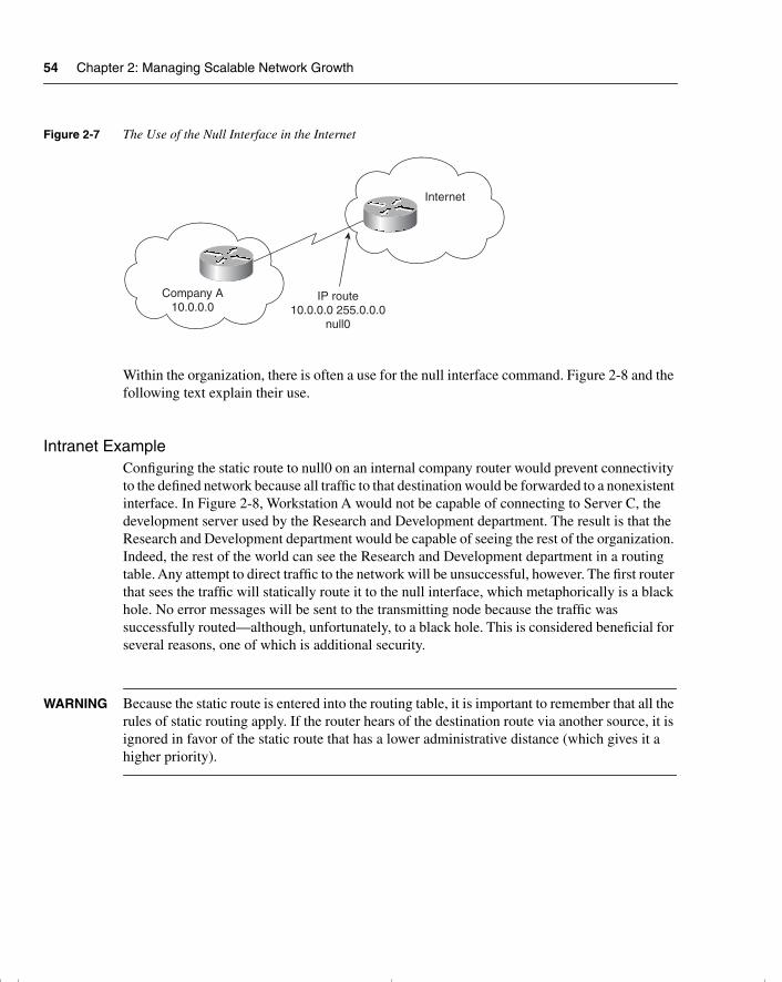
54 Chapter 2: Managing Scalable Network Growth
Figure 2-7 The Use of the Null Interface in the Internet
Within the organization, there is often a use for the null interface command. Figure 2-8 and the following text explain their use.
Intranet ExampleConfiguring the static route to null0 on an internal company router would prevent connectivity to the defined network because all traffic to that destination would be forwarded to a nonexistent interface. In Figure 2-8, Workstation A would not be capable of connecting to Server C, the development server used by the Research and Development department. The result is that the Research and Development department would be capable of seeing the rest of the organization. Indeed, the rest of the world can see the Research and Development department in a routing table. Any attempt to direct traffic to the network will be unsuccessful, however. The first router that sees the traffic will statically route it to the null interface, which metaphorically is a black hole. No error messages will be sent to the transmitting node because the traffic was successfully routed—although, unfortunately, to a black hole. This is considered beneficial for several reasons, one of which is additional security.
WARNING Because the static route is entered into the routing table, it is important to remember that all the rules of static routing apply. If the router hears of the destination route via another source, it is ignored in favor of the static route that has a lower administrative distance (which gives it a higher priority).
Company A10.0.0.0
Internet
IP route10.0.0.0 255.0.0.0
null0
chpt_01.book Page 54 Thursday, December 21, 2000 6:22 PM
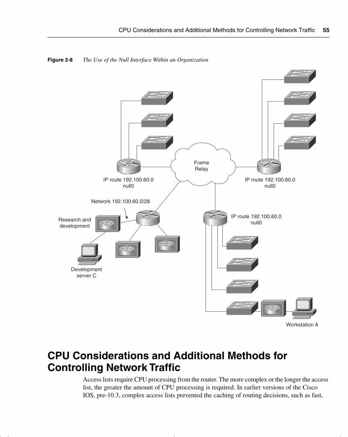
CPU Considerations and Additional Methods for Controlling Network Traffic 55
Figure 2-8 The Use of the Null Interface Within an Organization
CPU Considerations and Additional Methods for Controlling Network Traffic
Access lists require CPU processing from the router. The more complex or the longer the access list, the greater the amount of CPU processing is required. In earlier versions of the Cisco IOS, pre-10.3, complex access lists prevented the caching of routing decisions, such as fast,
FrameRelay
IP route 192.100.60.0null0
IP route 192.100.60.0null0
IP route 192.100.60.0null0
Network 192.100.60.0/28
Research anddevelopment
Developmentserver C
Workstation A
chpt_01.book Page 55 Thursday, December 21, 2000 6:22 PM
56 Chapter 2: Managing Scalable Network Growth
autonomous, and silicon switching. These functions are now supported, particularly if NetFlow features are turned on. In this context, switching refers to traffic forwarding, a Cisco solution that was implemented in the earliest of Cisco’s products and that has been consistently enhanced.
Fast, Autonomous, and Silicon SwitchingThese switching techniques were created to improve the capability of the router to forward traffic—at speed. The router caches the routing decisions it has made, which means that subsequent packets from the same source to the same destination do not have to be sent to the routing process, but instead can perform simple and speedy lookup.
After the routing process has made a routing decision, it sends the packet to the appropriate outbound interface. Meanwhile, the router holds a copy of the address details of the outbound frame in memory, along with a pointer to the appropriate outbound interface. This means that incoming traffic can be examined as it comes into the router. The router looks in the cache or memory to see whether a routing decision has already been made for that set of source and destination addresses. If an entry exists, the frame can be switched directly to the outbound interface, and the routing process is bypassed.
Cisco Express ForwardingThis is a very high-end solution and is available on 7500 routers with Versatile Interface Processors (VIPs) and the 8510. It is extremely fast and is used for high volumes of traffic. On some Cisco platforms, the Cisco processor automatically turns on this feature if the appropriate hardware and software are available.
NOTE A real performance gain can be realized with the reduction of CPU cycles needed when NetFlow or fast switching are used. In fact, the risk of losing packets or buffer overflow is reduced because the router is working a lot faster. The different names for the available switching methods refer to where the cache is stored. For more information on this subject, refer to the Cisco documentation set.
If the router is not caching any of the routing decisions but is instead processing every packet with process switching, there may be negative implications on the router’s CPU and memory utilization.
chpt_01.book Page 56 Thursday, December 21, 2000 6:22 PM
CPU Considerations and Additional Methods for Controlling Network Traffic 57
Placement of Client/ServerThe location of the servers in relation to the clients dramatically affects the traffic patterns within the network.
The current philosophy is to create server farms so that the servers can be centrally administered. If the client finds the server via broadcasts, however, a serious problem will arise if there is a router between the broadcasts: Because routers are a natural broadcast firewall, they treat broadcasts as an unknown address and discard them. In such a scenario, the client sending a broadcast to locate a server will fail in the endeavor.
The careful design with centralized server farms on different networks will not work because the broadcasts sent between the clients and the server to establish connections are discarded by the intervening router. The clients will have no connectivity with their servers. The solution is to configure a helper address on the router.
Even carefully designed centralized server farms on different networks will not work because the intervening router discards broadcasts sent between the clients and the server. The clients will have no connectivity with their servers. The solution is to configure a helper address on the router. This is described in the section, “IP Helper Address.”
Design Principles of a Client/Server Network To design an effective network, it is essential to understand the data flow within a network. Where to place the server relative to the clients should be decided only after considering the following factors:
• The frequency of connection to the server
• The duration of the connection to the server
• The volume of traffic sent across the link to and from the server at a specific moment of the day
• The daily quantified average
Analyzing the traffic patterns over time to create a baseline of the network documents how the network functions today and allows the correct determination of server/client placement. Using standard systems analysis methodology, the status of the network must then be set against the future needs of the organization (to ensure the appropriate design of the network). Understand that the design of the network will directly influence the traffic patterns experienced within the network.
IP Helper AddressThe IP helper address removes the broadcast destination address of a UDP packet received on an identified interface and replaces it with a specific destination address. The router has been
chpt_01.book Page 57 Thursday, December 21, 2000 6:22 PM
58 Chapter 2: Managing Scalable Network Growth
programmed to say, “If a broadcast comes in on this interface, forward it to this destination address,” where the destination address is that of the server.
A helper address is configured on the incoming interface. The destination address may be either an individual server or a subnet address. Multiple helper addresses can be identified, and all broadcasts received on the interface will be forwarded to each destination. This is a good way to create backup servers on different segments.
Configuration of IP Helper AddressThe syntax for the ip helper-address command is as follows:
ip helper-address address
The IP helper address forwards broadcasts for the following UDP ports:
• TFTP (69)
• DNS (53)
• Time (37)
• NetBIOS name server (137)
• NetBIOS datagram service (138)
• BOOTP server (67)
• BOOTP client (68)
• TACAS (49)
In addition to the helper address, the IP forward protocol instructs the router to forward broadcasts. By stating the port number, particular types of broadcast may be identified. This is very useful when used in conjunction with the helper address because it identifies those broadcasts to be readdressed to specified destinations. It is possible to either add to the list of broadcasts that will be forwarded with the helper address or remove certain traffic types. You can tailor the ip helper-address command so that only necessary traffic is forwarded, which not only optimizes bandwidth but also prevents the servers from being overloaded. (Server overload can result in servers overflowing their buffers; this causes them to slow down or hang.) The syntax for the ip forward-protocol command is as follows:
ip forward-protocol {UDP [port] |nd | sdns}
Enhanced Interior Gateway Routing ProtocolEIGRP was designed to make efficient use of the available network bandwidth. The routing protocol can be used for IP as well as AppleTalk and IPX. The advantage of EIGRP is that it is incremental, sending updates only when a change in the network is experienced.
chpt_01.book Page 58 Thursday, December 21, 2000 6:22 PM
CPU Considerations and Additional Methods for Controlling Network Traffic 59
EIGRP is particularly efficient in sending network and server information for such client/server products as NetWare for IPX and AppleTalk because it automatically redistributes routing updates into the local protocol updates. EIGRP is proprietary to Cisco and is understood only by other Cisco devices. A powerful use of this technology would be to have EIGRP as the routing protocol between the routers across the WAN and the client/server traffic on the local segments.
It is advisable to use the latest versions of the Cisco IOS when implementing this technology and to ensure that all the devices are running the same version of the protocol. This subject is dealt with in more detail in Chapter 7, “Using EIGRP in Enterprise Networks.”
WARNING If possible, all routers should run the same version of IOS because this may make troubleshooting easier.
Tunneling into IPTunneling one protocol into another is the process by which a protocol at a specific layer of the OSI model is wrapped into another protocol of the same layer or one higher in the stack. An example of this would be IPX, which is a Layer 3 protocol being wrapped inside IP, another Layer 3 protocol. Other examples include AppleTalk inside IP, and NetBIOS or source-route bridging encapsulated in IP—this is an example of a Layer 2 protocol being wrapped inside a Layer 3 protocol.
Figure 2-9 illustrates the steps of the IPX protocol being encapsulated and transported through an IP tunnel:
Step 1 Data from the application layer is passed down the OSI model to the network layer.
Step 2 At the network layer, the data is encapsulated in an IPX packet.
Step 3 At the network layer, the IPX packet is encapsulated into an IP packet.
Step 4 The IP packet is then inserted into the frame format at the data link layer for the media in which the frame will be sent out.
Why would anyone want to configure anything quite so torturous? Such a configuration certainly will not reduce or control the traffic propagated onto the network. Conversely, it will increase the traffic load because the original data will now have the additional header.
On the end routers, which are responsible for adding this extra header, there are obviously increased CPU requirements.
chpt_01.book Page 59 Thursday, December 21, 2000 6:22 PM
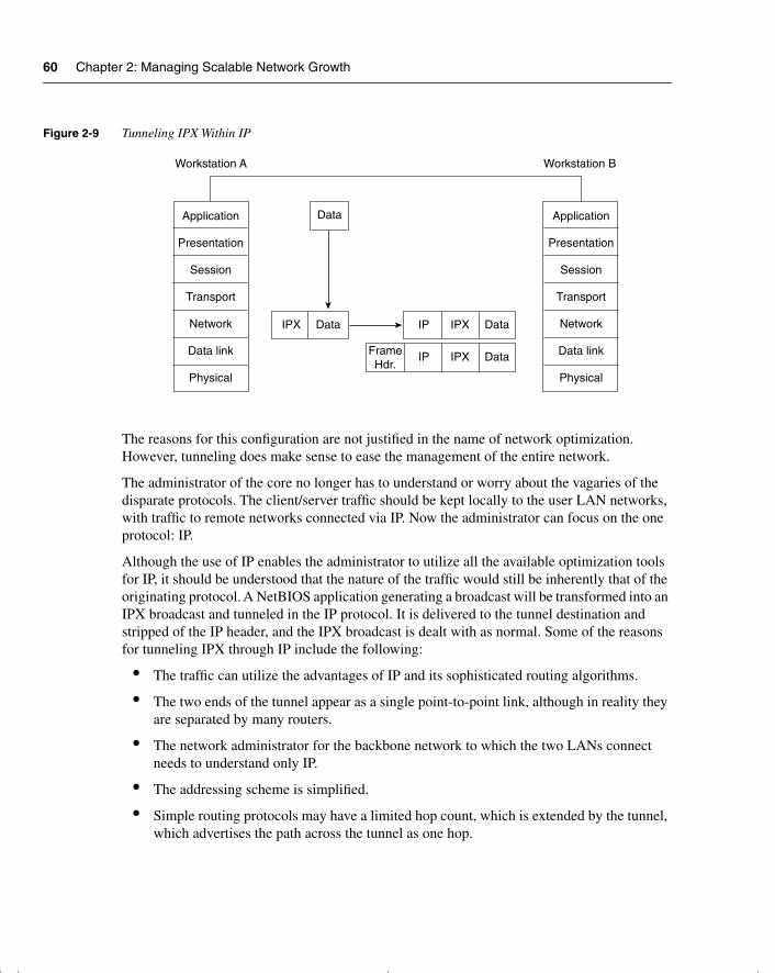
60 Chapter 2: Managing Scalable Network Growth
Figure 2-9 Tunneling IPX Within IP
The reasons for this configuration are not justified in the name of network optimization. However, tunneling does make sense to ease the management of the entire network.
The administrator of the core no longer has to understand or worry about the vagaries of the disparate protocols. The client/server traffic should be kept locally to the user LAN networks, with traffic to remote networks connected via IP. Now the administrator can focus on the one protocol: IP.
Although the use of IP enables the administrator to utilize all the available optimization tools for IP, it should be understood that the nature of the traffic would still be inherently that of the originating protocol. A NetBIOS application generating a broadcast will be transformed into an IPX broadcast and tunneled in the IP protocol. It is delivered to the tunnel destination and stripped of the IP header, and the IPX broadcast is dealt with as normal. Some of the reasons for tunneling IPX through IP include the following:
• The traffic can utilize the advantages of IP and its sophisticated routing algorithms.
• The two ends of the tunnel appear as a single point-to-point link, although in reality they are separated by many routers.
• The network administrator for the backbone network to which the two LANs connect needs to understand only IP.
• The addressing scheme is simplified.
• Simple routing protocols may have a limited hop count, which is extended by the tunnel, which advertises the path across the tunnel as one hop.
Application
Presentation
Session
Transport
Network
Data link
Physical
Application
Presentation
Session
Transport
Network
Data link
Physical
Data
DataIPX DataIPXIP
DataIPXIPFrameHdr.
Workstation A Workstation B
chpt_01.book Page 60 Thursday, December 21, 2000 6:22 PM
CPU Considerations and Additional Methods for Controlling Network Traffic 61
Some things to consider when creating an IP tunnel for IPX include the following:
• The delay, or latency, created in tunneling the IPX traffic into IP may cause some applications to time out.
• Because the tunnel is viewed as a point-to-point link, separate tunnels are required for multiple links. Many tunnels on a physical interface can cause some memory problems on the interface.
• Care must be taken in redistributing routing protocols because the tunnel is often seen as a preferred path. This is because the route is advertised as a single hop. It may involve a much less favorable path, however. The tunnel may advertise the path as two hops—one hop through the tunnel and one hop to the destination. However, the 1 hop actually represents 10 hops across mixed media. The other path, which is rejected because it advertised three hops, is really only three hops away.
Configuration of Tunneling into IPThe following syntax shows the configuration for the tunnel interface command:
interface tunnel interface-number
The following shows syntax for the configuration of the tunnel associated with the tunnel interface.
tunnel source interface-number | ip-addresstunnel destination hostname | ip-address
Table 2-3 explains the previous syntax.
The following example shows the use of the tunnel commands:
Router(config)#interface tunnel0Router(config-if))#tunnel source ethernet0Router(config-if)#tunnel destination 131.108.164.19
Table 2-3 Tunneling Configuration Explanation
Command Description
interface tunnel Creates the virtual interface
interface-number Identifies the interface number to be created
tunnel source Identifies the source of the tunnel
interface-number | ip-address Specifies the port, connector, or interface card number/IP address to use as the source address for packets in the tunnel.
tunnel destination Identifies the destination of the tunnel
hostname | ip-address Gives the IP address of the host destination expressed in decimal in four-part, dotted notation
chpt_01.book Page 61 Thursday, December 21, 2000 6:22 PM

62 Chapter 2: Managing Scalable Network Growth
ConclusionIP is the dominant protocol within the industry. Many companies have moved to an IP-based network, forbidding any other protocol on the wire, to manage the network more efficiently. Dealing with one protocol has its obvious benefits. Because IP is the chosen protocol of the industry, a lot of effort has been placed into enhancing the utilities and support provided.
This chapter has reviewed the means of scaling this IP network, allowing it to grow with an organization’s needs. Many design features, as well as Cisco features, allow the streamlining of the network. The following were considered:
• Network congestion, both its causes and symptoms
• How Cisco’s hierarchical design can scale your network
• IP access lists to limit traffic and control network overhead
• Alternatives to access lists for reducing network traffic, particularly in a client/server environment
You have seen that an understanding of the network structure and the needs of the users and applications will make it possible to manage traffic flow within that network. Therefore, network administrators must know the network and its idiosyncrasies.
It is important to remember that a structural topology map of the physical and logical layout of the network is necessary to allow the design and appropriate implementation of the features described in this chapter.
chpt_01.book Page 62 Thursday, December 21, 2000 6:22 PM
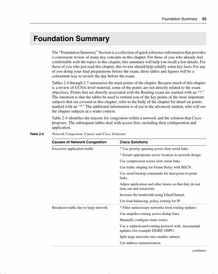
Foundation Summary 63
Foundation Summary
The “Foundation Summary” Section is a collection of quick reference information that provides a convenient review of many key concepts in this chapter. For those of you who already feel comfortable with the topics in this chapter, this summary will help you recall a few details. For those of you who just read this chapter, this review should help solidify some key facts. For any of you doing your final preparations before the exam, these tables and figures will be a convenient way to review the day before the exam.
Tables 2-4 through 2-7 summarize the main points of the chapter. Because much of this chapter is a review of CCNA-level material, some of the points are not directly related to the exam objectives. Points that are directly associated with the Routing exam are marked with an “*.” The intention is that the tables be used to remind you of the key points of the most important subjects that are covered in this chapter; refer to the body of the chapter for detail on points marked with an “*.” The additional information is of use to the advanced student, who will see the chapter subjects in a wider context.
Table 2-4 identifies the reasons for congestion within a network and the solution that Cisco proposes. The subsequent tables deal with access lists, including their configuration and application.
Table 2-4 Network Congestion: Causes and Cisco Solutions
Causes of Network Congestion Cisco Solutions
Excessive application traffic * Use priority queuing across slow serial links.
* Ensure appropriate server location in network design.
Use compression across slow serial links.
Use traffic shaping for Frame Relay with BECN.
Use serial backup commands for dual point-to-point links.
Adjust application and other timers so that they do not time out and retransmit.
Increase the bandwidth using EtherChannel.
Use load balancing, policy routing for IP .
Broadcast traffic due to large network * Filter unnecessary networks from routing updates.
Use snapshot routing across dialup lines.
Manually configure static routes.
Use a sophisticated routing protocol with incremental updates (for example EIGRP, OSPF).
Split large networks into smaller subnets.
Use address summarization.
continues
chpt_01.book Page 63 Thursday, December 21, 2000 6:22 PM
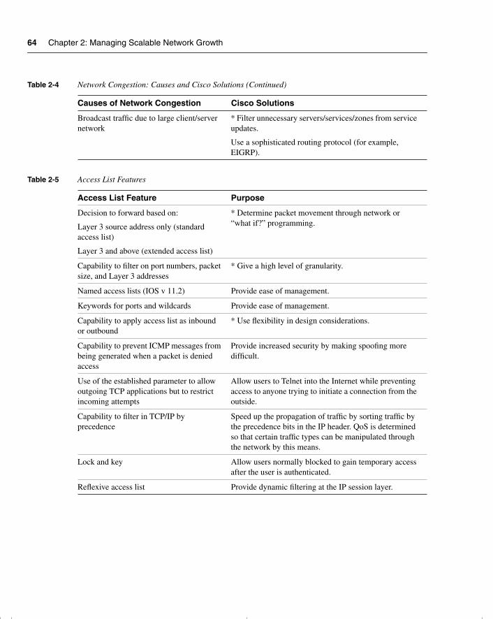
64 Chapter 2: Managing Scalable Network Growth
Broadcast traffic due to large client/server network
* Filter unnecessary servers/services/zones from service updates.
Use a sophisticated routing protocol (for example, EIGRP).
Table 2-5 Access List Features
Access List Feature Purpose
Decision to forward based on:
Layer 3 source address only (standard access list)
Layer 3 and above (extended access list)
* Determine packet movement through network or “what if?” programming.
Capability to filter on port numbers, packet size, and Layer 3 addresses
* Give a high level of granularity.
Named access lists (IOS v 11.2) Provide ease of management.
Keywords for ports and wildcards Provide ease of management.
Capability to apply access list as inbound or outbound
* Use flexibility in design considerations.
Capability to prevent ICMP messages from being generated when a packet is denied access
Provide increased security by making spoofing more difficult.
Use of the established parameter to allow outgoing TCP applications but to restrict incoming attempts
Allow users to Telnet into the Internet while preventing access to anyone trying to initiate a connection from the outside.
Capability to filter in TCP/IP by precedence
Speed up the propagation of traffic by sorting traffic by the precedence bits in the IP header. QoS is determined so that certain traffic types can be manipulated through the network by this means.
Lock and key Allow users normally blocked to gain temporary access after the user is authenticated.
Reflexive access list Provide dynamic filtering at the IP session layer.
Table 2-4 Network Congestion: Causes and Cisco Solutions (Continued)
Causes of Network Congestion Cisco Solutions
chpt_01.book Page 64 Thursday, December 21, 2000 6:22 PM
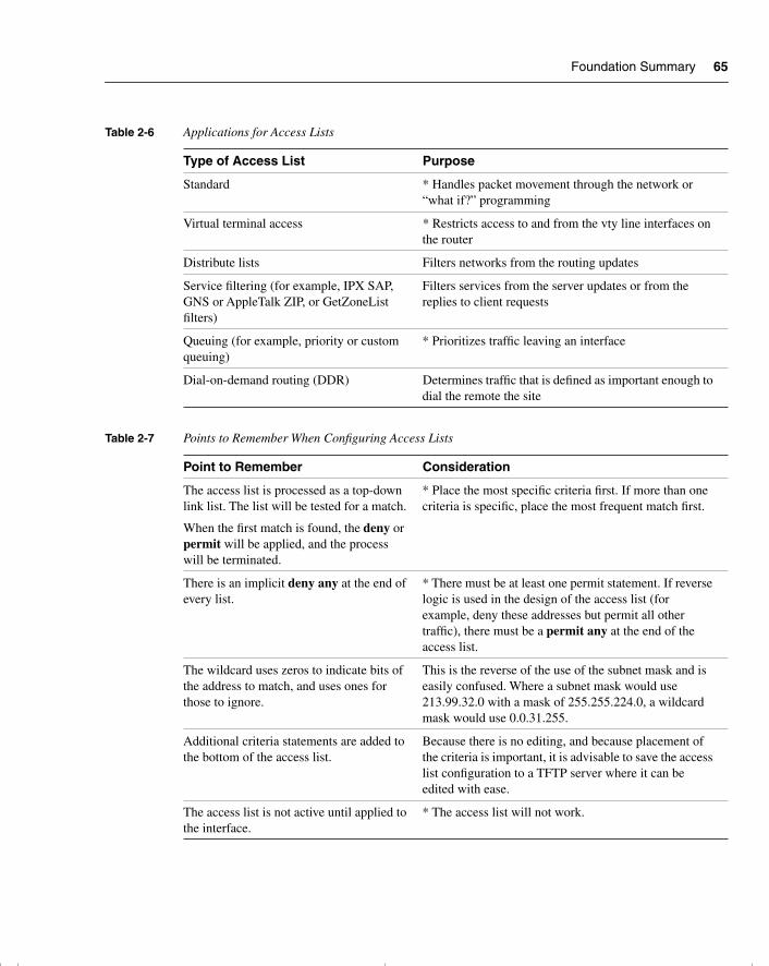
Foundation Summary 65
Table 2-6 Applications for Access Lists
Type of Access List Purpose
Standard * Handles packet movement through the network or “what if?” programming
Virtual terminal access * Restricts access to and from the vty line interfaces on the router
Distribute lists Filters networks from the routing updates
Service filtering (for example, IPX SAP, GNS or AppleTalk ZIP, or GetZoneList filters)
Filters services from the server updates or from the replies to client requests
Queuing (for example, priority or custom queuing)
* Prioritizes traffic leaving an interface
Dial-on-demand routing (DDR) Determines traffic that is defined as important enough to dial the remote the site
Table 2-7 Points to Remember When Configuring Access Lists
Point to Remember Consideration
The access list is processed as a top-down link list. The list will be tested for a match.
When the first match is found, the deny or permit will be applied, and the process will be terminated.
* Place the most specific criteria first. If more than one criteria is specific, place the most frequent match first.
There is an implicit deny any at the end of every list.
* There must be at least one permit statement. If reverse logic is used in the design of the access list (for example, deny these addresses but permit all other traffic), there must be a permit any at the end of the access list.
The wildcard uses zeros to indicate bits of the address to match, and uses ones for those to ignore.
This is the reverse of the use of the subnet mask and is easily confused. Where a subnet mask would use 213.99.32.0 with a mask of 255.255.224.0, a wildcard mask would use 0.0.31.255.
Additional criteria statements are added to the bottom of the access list.
Because there is no editing, and because placement of the criteria is important, it is advisable to save the access list configuration to a TFTP server where it can be edited with ease.
The access list is not active until applied to the interface.
* The access list will not work.
chpt_01.book Page 65 Thursday, December 21, 2000 6:22 PM
66 Chapter 2: Managing Scalable Network Growth
Chapter GlossaryThis glossary provides an official Cisco definition for key words and terms introduced in this chapter. I have supplied my own definition for terms that the Cisco glossary does not contain. The words listed here are identified in the text by italics. A complete glossary, including all the chapter terms and additional terms, can be found in Appendix C, “Glossary.”
connection-orientated—Software on two end nodes guarantees the transmission of network traffic because a circuit setup is established before sending any data. It requires the use of sequencing, windowing, and acknowledgements.
distribute list—An access list that is used to filter networks out of routing updates.
end node—A device that is connected to the network.
NetFlow—A Cisco solution that enhances the speed of transmission by caching routing decisions.
network congestion—A condition in which excessive traffic on the network is the cause of delays and packet loss.
routing loop—Occurs when routers have misinformation about the network and, instead of sending traffic to the destination, pass the packets between themselves in the belief that the other router knows the path.
runaway congestion—A condition in which the results of network congestion cause the network to generate more traffic and compound the problem.
server—A node or software program that provides services to clients.
chpt_01.book Page 66 Thursday, December 21, 2000 6:22 PM
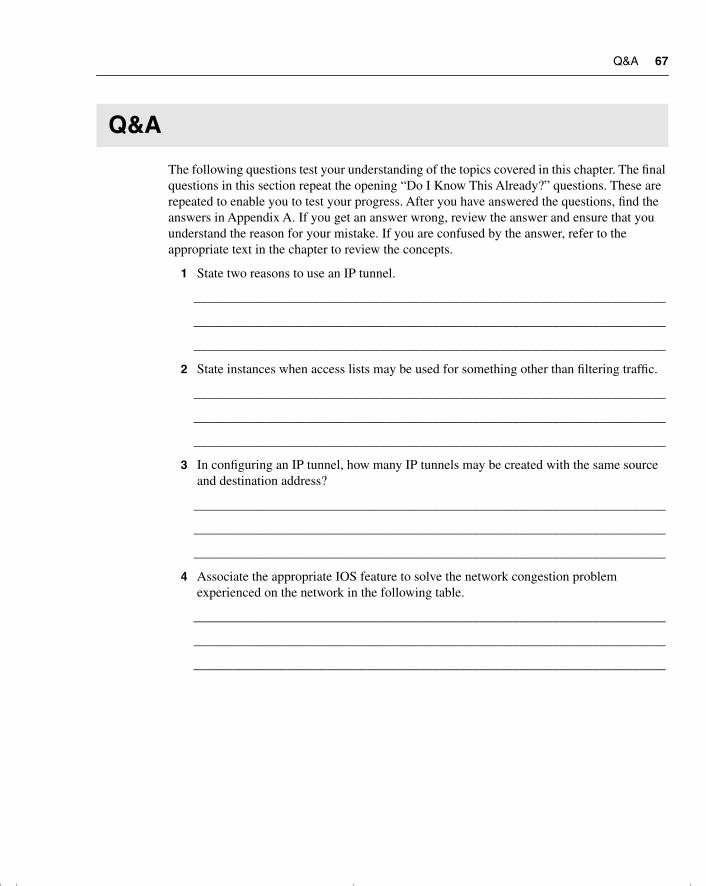
Q&A 67
Q&A
The following questions test your understanding of the topics covered in this chapter. The final questions in this section repeat the opening “Do I Know This Already?” questions. These are repeated to enable you to test your progress. After you have answered the questions, find the answers in Appendix A. If you get an answer wrong, review the answer and ensure that you understand the reason for your mistake. If you are confused by the answer, refer to the appropriate text in the chapter to review the concepts.
1 State two reasons to use an IP tunnel.
_______________________________________________________________________
_______________________________________________________________________
_______________________________________________________________________
2 State instances when access lists may be used for something other than filtering traffic.
_______________________________________________________________________
_______________________________________________________________________
_______________________________________________________________________
3 In configuring an IP tunnel, how many IP tunnels may be created with the same source and destination address?
_______________________________________________________________________
_______________________________________________________________________
_______________________________________________________________________
4 Associate the appropriate IOS feature to solve the network congestion problem experienced on the network in the following table.
_______________________________________________________________________
_______________________________________________________________________
_______________________________________________________________________
chpt_01.book Page 67 Thursday, December 21, 2000 6:22 PM
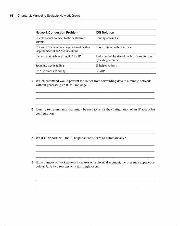
68 Chapter 2: Managing Scalable Network Growth
5 Which command would prevent the router from forwarding data to a remote network without generating an ICMP message?
______________________________________________________________________
______________________________________________________________________
______________________________________________________________________
6 Identify two commands that might be used to verify the configuration of an IP access list configuration.
______________________________________________________________________
______________________________________________________________________
______________________________________________________________________
7 What UDP ports will the IP helper address forward automatically?
______________________________________________________________________
______________________________________________________________________
______________________________________________________________________
8 If the number of workstations increases on a physical segment, the user may experience delays. Give two reasons why this might occur.
______________________________________________________________________
______________________________________________________________________
______________________________________________________________________
Network Congestion Problem IOS Solution
Clients cannot connect to the centralized servers
Routing access list
Cisco environment in a large network with a large number of WAN connections
Prioritization on the interface
Large routing tables using RIP for IP Reduction of the size of the broadcast domain by adding a router
Spanning tree is failing IP helper address
SNA sessions are failing EIGRP
chpt_01.book Page 68 Thursday, December 21, 2000 6:22 PM
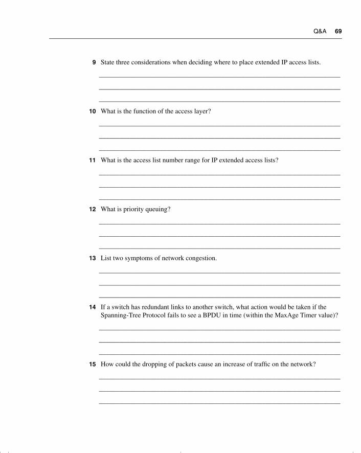
Q&A 69
9 State three considerations when deciding where to place extended IP access lists.
_______________________________________________________________________
_______________________________________________________________________
_______________________________________________________________________
10 What is the function of the access layer?
_______________________________________________________________________
_______________________________________________________________________
_______________________________________________________________________
11 What is the access list number range for IP extended access lists?
_______________________________________________________________________
_______________________________________________________________________
_______________________________________________________________________
12 What is priority queuing?
_______________________________________________________________________
_______________________________________________________________________
_______________________________________________________________________
13 List two symptoms of network congestion.
_______________________________________________________________________
_______________________________________________________________________
_______________________________________________________________________
14 If a switch has redundant links to another switch, what action would be taken if the Spanning-Tree Protocol fails to see a BPDU in time (within the MaxAge Timer value)?
_______________________________________________________________________
_______________________________________________________________________
_______________________________________________________________________
15 How could the dropping of packets cause an increase of traffic on the network?
_______________________________________________________________________
_______________________________________________________________________
_______________________________________________________________________
chpt_01.book Page 69 Thursday, December 21, 2000 6:22 PM

70 Chapter 2: Managing Scalable Network Growth
16 How might network congestion cause a loss of services?
______________________________________________________________________
______________________________________________________________________
______________________________________________________________________
17 In Cisco’s hierarchical design, what is the function of the core layer?
______________________________________________________________________
______________________________________________________________________
______________________________________________________________________
18 In Cisco’s hierarchical design, where is the access layer located?
______________________________________________________________________
______________________________________________________________________
______________________________________________________________________
19 In the hierarchical design suggested by Cisco, at which layer are access lists not recommended?
______________________________________________________________________
______________________________________________________________________
______________________________________________________________________
20 What is the function of the distribution layer?
______________________________________________________________________
______________________________________________________________________
______________________________________________________________________
21 If an access list is configured as an inbound list, will the packet be sent to the routing process?
______________________________________________________________________
______________________________________________________________________
______________________________________________________________________
22 State three uses of access lists.
______________________________________________________________________
______________________________________________________________________
______________________________________________________________________
chpt_01.book Page 70 Thursday, December 21, 2000 6:22 PM
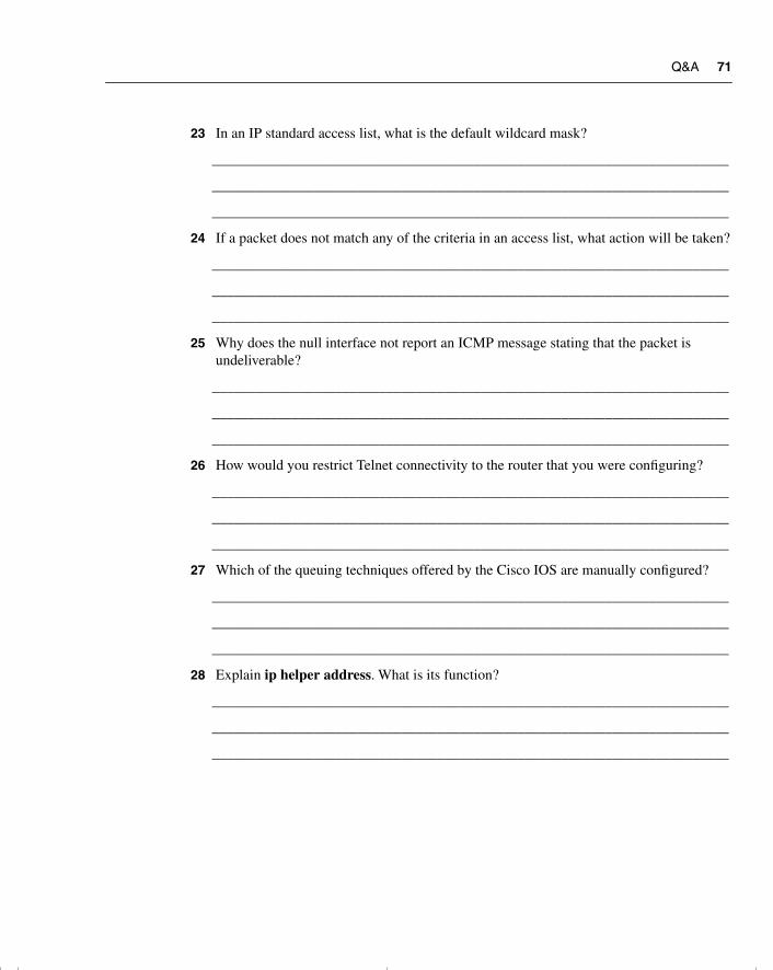
Q&A 71
23 In an IP standard access list, what is the default wildcard mask?
_______________________________________________________________________
_______________________________________________________________________
_______________________________________________________________________
24 If a packet does not match any of the criteria in an access list, what action will be taken?
_______________________________________________________________________
_______________________________________________________________________
_______________________________________________________________________
25 Why does the null interface not report an ICMP message stating that the packet is undeliverable?
_______________________________________________________________________
_______________________________________________________________________
_______________________________________________________________________
26 How would you restrict Telnet connectivity to the router that you were configuring?
_______________________________________________________________________
_______________________________________________________________________
_______________________________________________________________________
27 Which of the queuing techniques offered by the Cisco IOS are manually configured?
_______________________________________________________________________
_______________________________________________________________________
_______________________________________________________________________
28 Explain ip helper address. What is its function?
_______________________________________________________________________
_______________________________________________________________________
_______________________________________________________________________
chpt_01.book Page 71 Thursday, December 21, 2000 6:22 PM
72 Chapter 2: Managing Scalable Network Growth
Scenarios
The following scenarios and questions are designed to draw together the content of the chapter and to exercise your understanding of the concepts. There is not necessarily a right answer. The thought process and practice in manipulating the concepts is the goal of this section. The answers to the scenario questions are found at the end of this chapter.
Scenario 2-1The company Pedopodgy, which is a private college, realized the need to network the central administrative offices five years ago. The initial network comprised of 45 PCs, 5 print servers, and 1 file server. The company had a NetWare network, running IP. The administration at each of the five campuses was added two years later. Last year, Pedopodgy provided Internet access for each student, with Internet connectivity accessed through corporate headquarters.
As can be seen, the network has grown considerably in the last five years, in both end nodes and complexity. In end nodes alone, the network has grown from 45 PCs, with the 5 print servers and 1 file server, to more than 500 PCs connecting to 30 print servers and 20 file servers.
Everyone is complaining. The network is unreliable and unresponsive, it is difficult to use, and there have been several security break-ins. The main problem is that the network has exceeded its original design, and the infrastructure of the network can no longer handle the volume of traffic generated. The IT department is being besieged by angry users.
Figure 2-10 shows the network diagram for Scenario 2-1.
1 Give recommendations for the administrator to implement when trying to solve the problem of network delay.
2 Users on the network no longer have connectivity to the e-mail server. Upon investigation, you notice that the access list commands have been changed. What are the commands to remedy the situation?
Router(config-fi)#access list 110 permit 10.10.10.10 255.255.255.255 eq smtp
3 Noticing that someone has been changing the configuration of the routers, you decide to implement some first-line security. State some of the solutions that you might consider.
chpt_01.book Page 72 Thursday, December 21, 2000 6:22 PM
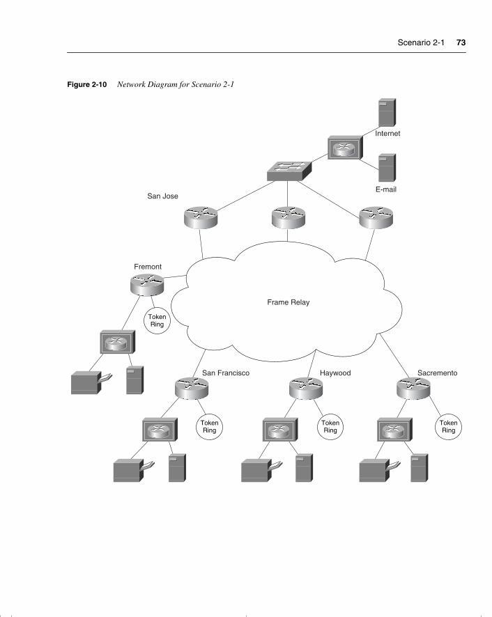
Scenario 2-1 73
Figure 2-10 Network Diagram for Scenario 2-1
TokenRing
TokenRing
TokenRing
Frame Relay
SacrementoHaywoodSan Francisco
Internet
TokenRing
Fremont
San Jose
chpt_01.book Page 73 Thursday, December 21, 2000 6:22 PM
74 Chapter 2: Managing Scalable Network Growth
Scenario 2-2Your company has recently created a lab for you to test TCP/IP configurations and explore new solutions. Although the lab needs to be connected to the entire network, it is important that access to this environment be limited. Although you need to be able to connect from anywhere in the lab to the network, no one else should have this access.
1 Write the access list(s) to achieve this, and apply them to the appropriate interface(s) of the appropriate routers(s).
2 Draw a diagram to support your configuration.
Scenario 2-3In one of the buildings of the network campus, the local administrators have decided that they want to centrally administer the building servers. Each floor of the building is a separate IPX and IP network. The server farm is located in the network in the basement. The server farm consists of a DHCP server, a DNS server, and an IPX file server. None of the clients have been configured with the addresses of the servers.
The IP network address for the basement is 10.10.10.0. 255.255.255.0
1 Draw a diagram of the network.
2 What command would allow connectivity of the users to the servers held in the server farm?
3 Write the configuration commands to achieve the requirements stated previously. Make sure that this is reflected on your diagram.
4 Which commands would you use to verify the configuration?
chpt_01.book Page 74 Thursday, December 21, 2000 6:22 PM
Scenario 2-1 Answers 75
Scenario Answers
The answers are in bold. The answers provided in this section are not necessarily the only possible answers to the questions. The questions are designed to test your knowledge and to give practical exercise in certain key areas. This section is intended to test and exercise skills and concepts detailed in the body of this chapter.
If your answer is different, ask yourself whether it follows the tenants explained in the answers provided. Your answer is correct not if it matches the solution provided in the book, but rather if it has included the principles of design laid out in the chapter.
In this way, the testing provided in these scenarios is deeper: It examines not only your knowledge, but also your understanding and ability to apply that knowledge to problems.
If you do not get the correct answer, refer back to the text and review the subject tested. Be certain to also review your notes on the question to ensure that you understand the principles of the subject.
Scenario 2-1 Answers1 Give recommendations for the administrator to implement when trying to solve the
problem of network delay.
The administrator could implement the following recommendations to ascertain that delays were being experienced on the network. Also listed here are some possible solutions to the problems.
— Use a protocol analyzer to verify that there is network congestion.
— Write an IP extended access list to prevent users from connecting to any server other than their local server, the e-mail server, or the gateway server.
2 Users on the network no longer have connectivity to the e-mail server. Upon investigation, you notice that the access list commands have been changed. What are the commands to remedy the situation?
Router(config-fi)#access list 110 permit 10.10.10.10 255.255.255.255 eq smtp
The problem with the access list is that it has had the source and destination transposed. The access list should read as follows:
Router(config-if)#access list 110 permit 10.10.10.10 255.255.255.255 eq smtp
3 Noticing that someone has been changing the configuration of the routers, you decide to implement some first-line security. State some of the solutions that you might consider.
chpt_01.book Page 75 Thursday, December 21, 2000 6:22 PM
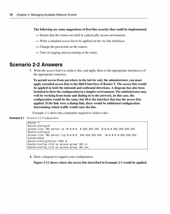
76 Chapter 2: Managing Scalable Network Growth
The following are some suggestions of first-line security that could be implemented:
— Ensure that the routers are held in a physically secure environment.
— Write a standard access list to be applied on the vty line interfaces.
— Change the passwords on the routers.
— Turn on logging and accounting at the router.
Scenario 2-2 Answers1 Write the access list(s) to achieve this, and apply them to the appropriate interface(s) of
the appropriate routers(s).
To permit access from anywhere in the lab for only the administrator, you must apply extended access lists to the fddi 0 interface of Router Y. The access lists would be applied in both the inbound and outbound directions. A diagram has also been included to show the configuration in a simpler environment. The administrator may well be working from home and dialing in to the network. In this case, the configuration would be the same, but S0 is the interface that has the access lists applied. If the link were a dialup link, there would be additional configuration determining which traffic would raise the line.
Example 2-1 shows the commands required to achieve this:
2 Draw a diagram to support your configuration.
Figure 2-11 shows where the access lists described in Example 2-1 would be applied.
Example 2-1 Scenario 2-2 Configuration
Router YRouter(config)#access-list 102 permit ip 10.0.0.0 0.255.255.255 0.0.0.0 255.255.255.255Router(config)#access-list 103 permit tcp 0.0.0.0 255.255.255.255 10.0.0.0 0.255.255.255 establishedRouter(config)#inter FDDI 0 Router(config-if)# ip access-group 102 inRouter(config-if)# ip access-group 103 out
chpt_01.book Page 76 Thursday, December 21, 2000 6:22 PM
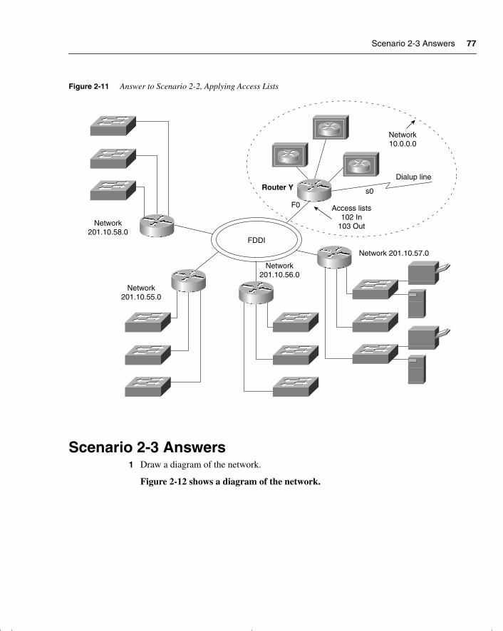
Scenario 2-3 Answers 77
Figure 2-11 Answer to Scenario 2-2, Applying Access Lists
Scenario 2-3 Answers1 Draw a diagram of the network.
Figure 2-12 shows a diagram of the network.
FDDI
Network10.0.0.0
Dialup line
s0Router Y
F0 Access lists102 In
103 Out
Network 201.10.57.0
Network201.10.56.0
Network201.10.58.0
Network201.10.55.0
chpt_01.book Page 77 Thursday, December 21, 2000 6:22 PM
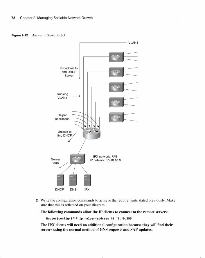
78 Chapter 2: Managing Scalable Network Growth
Figure 2-12 Answer to Scenario 2-3
2 Write the configuration commands to achieve the requirements stated previously. Make sure that this is reflected on your diagram.
The following commands allow the IP clients to connect to the remote servers:
Router(config-if)# ip helper-address 10.10.10.255
The IPX clients will need no additional configuration because they will find their servers using the normal method of GNS requests and SAP updates.
Helperaddresses
Unicast tofind DHCP
TrunkingVLANs
Broadcast tofind DHCP
Server
VLAN1
Serverfarm
IPX network: FABIP network: 10.10.10.0
DHCP DNS IPX
chpt_01.book Page 78 Thursday, December 21, 2000 6:22 PM

Scenario 2-3 Answers 79
3 Which commands would you use to verify the configuration?
The commands that you can use to verify the configuration of the helper addresses are as follows:
— show startup-config
— show running-config
— show ip interface
— show ipx interface
chpt_01.book Page 79 Thursday, December 21, 2000 6:22 PM
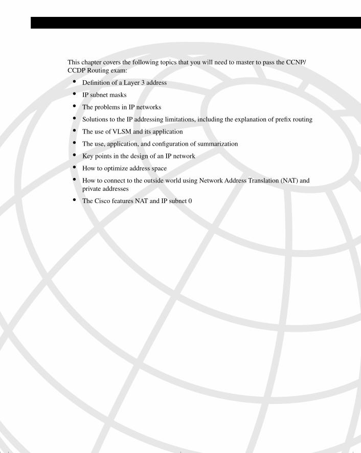
This chapter covers the following topics that you will need to master to pass the CCNP/CCDP Routing exam:
• Definition of a Layer 3 address
• IP subnet masks
• The problems in IP networks
• Solutions to the IP addressing limitations, including the explanation of prefix routing
• The use of VLSM and its application
• The use, application, and configuration of summarization
• Key points in the design of an IP network
• How to optimize address space
• How to connect to the outside world using Network Address Translation (NAT) and private addresses
• The Cisco features NAT and IP subnet 0
chpt_01.book Page 80 Thursday, December 21, 2000 6:22 PM
C H A P T E R 3
IP Addressing
This chapter is fundamental to the rest of the topics discussed within this book and will directly reflect questions on the exam. If you do not thoroughly understand the contents of this chapter, it is safe to say that it will be impossible to pass the exam. The entire Routing exam is based on IP addressing. For this reason, IP addressing is reviewed thoroughly in this book. Some of this chapter will review subjects dealt with in the Interconnecting Network Devices (ICND) course. The subsequent chapters will assume your comprehension of the subjects within this chapter.
How to Best Use This ChapterBy taking the following steps, you can make better use of your study time:
• Keep your notes and the answers for all your work with this book in one place, for easy reference.
• When you take a quiz, write down your answers. Studies show that retention significantly increases by writing down facts and concepts, even if you never look at the information again.
• Use the diagram in Figure 3-1 to guide you to the next step.
chpt_01.book Page 81 Thursday, December 21, 2000 6:22 PM
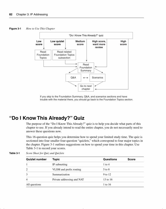
82 Chapter 3: IP Addressing
Figure 3-1 How to Use This Chapter
“Do I Know This Already?” QuizThe purpose of the “Do I Know This Already?” quiz is to help you decide what parts of this chapter to use. If you already intend to read the entire chapter, you do not necessarily need to answer these questions now.
This 16-question quiz helps you determine how to spend your limited study time. The quiz is sectioned into four smaller four-question “quizlets,” which correspond to four major topics in the chapter. Figure 3-1 outlines suggestions on how to spend your time in this chapter. Use Table 3-1 to record your scores.
Table 3-1 Score Sheet for Quiz and Quizlets
Quizlet number Topic Questions Score
1 IP subnetting 1 to 4
2 VLSM and prefix routing 5 to 8
3 Summarization 9 to 12
4 Private addressing and NAT 13 to 16
All questions 1 to 16
Lowscore
Low quizletscore
Mediumscore
High score,want more
review
Highscore
"Do I Know This Already?" quiz
ReadFoundation
Topics
Read relatedFoundation Topics
subsection
ReadFoundationSummary
Q&A Scenarios
Go to nextchapter
If you skip to the Foundation Summary, Q&A, and scenarios sections and havetrouble with the material there, you should go back to the Foundation Topics section.
chpt_01.book Page 82 Thursday, December 21, 2000 6:22 PM

“Do I Know This Already?” Quiz 83
1 If given a Class C address with the requirement to accommodate 14 subnets and 10 hosts on each subnet, what subnet mask would you use?
_______________________________________________________________________
_______________________________________________________________________
_______________________________________________________________________
2 List the range of hosts available on the 136.122.10.192/28 subnet.
_______________________________________________________________________
_______________________________________________________________________
_______________________________________________________________________
3 Convert the subnet address 56.98.5.0/24 to binary notation, and state the class to which it belongs.
_______________________________________________________________________
_______________________________________________________________________
_______________________________________________________________________
4 Write out the decimal notation of the following subnet mask presented in this binary notation:
11111111.11111111.11111111.11111000
_______________________________________________________________________
_______________________________________________________________________
_______________________________________________________________________
5 What does VLSM stand for?
_______________________________________________________________________
_______________________________________________________________________
_______________________________________________________________________
6 The Class B network address of 133.222.0.0 has been given a mask of 255.255.255.0. The subnets, 133.222.8.0, 133.222.9.0, 133.222.10.0, 133.222.11.0, 133.222.12.0, 133.222.13.0, and 133.222.14.0 need to be summarized using VLSM. Give the subnet and new mask to achieve this summarization.
_______________________________________________________________________
_______________________________________________________________________
_______________________________________________________________________
chpt_01.book Page 83 Thursday, December 21, 2000 6:22 PM
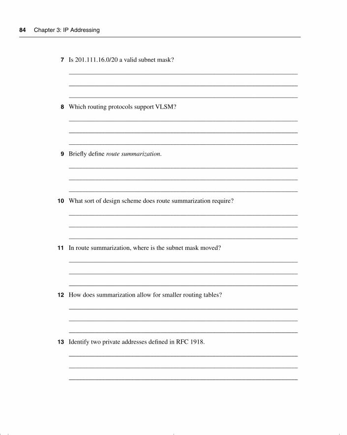
84 Chapter 3: IP Addressing
7 Is 201.111.16.0/20 a valid subnet mask?
______________________________________________________________________
______________________________________________________________________
______________________________________________________________________
8 Which routing protocols support VLSM?
______________________________________________________________________
______________________________________________________________________
______________________________________________________________________
9 Briefly define route summarization.
______________________________________________________________________
______________________________________________________________________
______________________________________________________________________
10 What sort of design scheme does route summarization require?
______________________________________________________________________
______________________________________________________________________
______________________________________________________________________
11 In route summarization, where is the subnet mask moved?
______________________________________________________________________
______________________________________________________________________
______________________________________________________________________
12 How does summarization allow for smaller routing tables?
______________________________________________________________________
______________________________________________________________________
______________________________________________________________________
13 Identify two private addresses defined in RFC 1918.
______________________________________________________________________
______________________________________________________________________
______________________________________________________________________
chpt_01.book Page 84 Thursday, December 21, 2000 6:22 PM
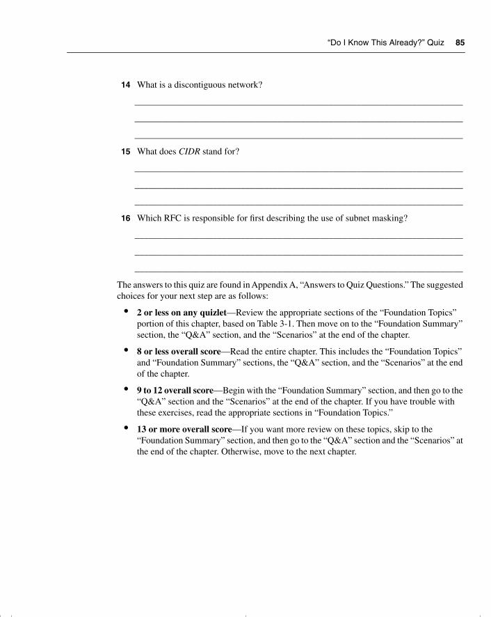
“Do I Know This Already?” Quiz 85
14 What is a discontiguous network?
_______________________________________________________________________
_______________________________________________________________________
_______________________________________________________________________
15 What does CIDR stand for?
_______________________________________________________________________
_______________________________________________________________________
_______________________________________________________________________
16 Which RFC is responsible for first describing the use of subnet masking?
_______________________________________________________________________
_______________________________________________________________________
_______________________________________________________________________
The answers to this quiz are found in Appendix A, “Answers to Quiz Questions.” The suggested choices for your next step are as follows:
• 2 or less on any quizlet—Review the appropriate sections of the “Foundation Topics” portion of this chapter, based on Table 3-1. Then move on to the “Foundation Summary” section, the “Q&A” section, and the “Scenarios” at the end of the chapter.
• 8 or less overall score—Read the entire chapter. This includes the “Foundation Topics” and “Foundation Summary” sections, the “Q&A” section, and the “Scenarios” at the end of the chapter.
• 9 to 12 overall score—Begin with the “Foundation Summary” section, and then go to the “Q&A” section and the “Scenarios” at the end of the chapter. If you have trouble with these exercises, read the appropriate sections in “Foundation Topics.”
• 13 or more overall score—If you want more review on these topics, skip to the “Foundation Summary” section, and then go to the “Q&A” section and the “Scenarios” at the end of the chapter. Otherwise, move to the next chapter.
chpt_01.book Page 85 Thursday, December 21, 2000 6:22 PM
86 Chapter 3: IP Addressing
Foundation Topics
Introduction: What Is a Layer 3 Address and How Does It Affect My Life?
The following case study illustrates some of the common issues that companies deal with as they grow. The company is often so focused on surviving infancy that it overlooks the internal technology requirements. This case study shows the problems seen when the network outgrows its addressing scheme.
Case Study A small startup company, Mental Merge, has grown in the last year. No longer three recent college graduates, working out of a parent’s guestroom, the founders now have their own premises and 100 employees.
The company has a flat, switched network providing print and file services using NT over IP. The owners have been simply adding devices as needed, without much heed to the future requirements of the company. Having run out of IP addresses once, and with an increase in delays, they realize that it is time to build an infrastructure with a well thought-out design and addressing scheme.
Networks, like children, grow. Often when you least suspect, you wake up and find them bigger, more complex, and thus more challenging. For many companies, although the network provides the tools by which the company does business, it is an irritating distraction from the business in hand. This was the case for Mental Merge. The owners were intelligent enough to string wire between PCs and read enough of the manual to install the client/server software. However, realizing that the company needs their full attention, they have just hired a network administrator.
Because Mental Merge is a small company, the owners hope to be bought out, so they intend to design an addressing scheme that will allow them to easily integrate into a larger network. Eventually, the network will be a routed one, and the addressing scheme certainly will reflect this intention.
This chapter considers many of the tasks that the new administrator must handle in readdressing the network with a design that enables future growth.
The Need for Layer 3 Addressing A quick review of addressing at Layer 3 should remind you of the importance of the ability to overcome the need for broadcasts, which are the bane of a switched environment. This is a particular problem in a client/server environment, as Mental Merge is beginning to realize.
chpt_01.book Page 86 Thursday, December 21, 2000 6:22 PM
Introduction: What Is a Layer 3 Address and How Does It Affect My Life? 87
A Definition of a Layer 3 AddressA Layer 3 address allows network traffic to be directed to a specific destination. The whole purpose of any address is to find a specific destination, whether the address of a restaurant or the company e-mail server. To be directed, every address is hierarchical; just as a restaurant is in a city, on a street, at a street number, the e-mail server is on a network at a host number.
Network Structures and Data FlowFor data to be sent to its destination directly, the underlying physical structure, or wiring, should support the logical structure, or the Layer 3 addressing. It also seems reasonable that this structure should reflect the organizational data flow. It would make sense for servers to be accessible to departments that share information and for the physical wiring and logical addressing to support this sharing of resources. Therefore, the servers may be physically adjacent and on the same IP subnet. The reason that both the physical and the logical structure of the network should support the organizational data flow is that, without this structure, application data can wander throughout your network inefficiently, clogging up available bandwidth.
This chapter reviews some of the fundamental concepts of IP addressing. After mastering its subtleties, you will then be able to consider the network management power that results from careful design of the IP addressing scheme.
The Network and How It Is AddressedLayer 3 provides the capability to logically address the network. The question is, what is a network? It is given many meanings, from describing a corporation’s international computer system to describing a single piece of wire. It has been complicated further with the recent capability to override the traditional physical limitations of address allocation. The use of switched environments and VLANs, as well as the use of dynamic addressing with DHCP, has provided new challenges to the design rules of address allocation.
A Confusion of Network TerminologyTo appreciate fully the power and purpose of the Layer 3 address, it is important to understand the meaning of the term network (as defined by Layer 3).
A network address has two parts: the network and the host portions. The host portion of the address identifies the individual device within a group. The network portion identifies a group of individual devices.
Unfortunately, the term network is used loosely; although it is often defined, the term is seldom understood. In addition, the term network appears in several different contexts, compounding the confusion created for the user.
chpt_01.book Page 87 Thursday, December 21, 2000 6:22 PM
88 Chapter 3: IP Addressing
It is increasingly important to have an accurate definition of a network because new technology—such as VLANs and Layer 3 switching—have blurred the distinctions between the different layers of the OSI model.
Network Terms ExplainedThe following list outlines the various uses of the term network:
• The piece of wire or physical medium to which a group of devices are connected. This is more accurately defined as a segment.
• A Layer 3 network.
• The local-area network (LAN).
• The corporate or organizational network.
For our purposes, the term network refers to the Layer 3 network.
A Definition of a Layer 3 NetworkThe network portion of a Layer 3 address is a border chosen by an administrator to group end devices. This group is given an identifier or label, which is the network number.
Network CharacteristicsA Layer 3 network address has the following characteristics:
• It defines a group of end devices or hosts.
• The address is hierarchical, which allows decisions to be made on groups of devices.
• The devices running the Layer 3 protocol do not forward broadcasts.
• The group of identified devices is given a label to identify the group. This is the network number.
• The group address combined with their unique membership number for that group identifies the end device. This is the host address.
• Although the identifier for the end device may not be unique to the organization, it will be unique to the group or network.
• If the addressing is carefully planned and the addressing scheme allows, groups may be grouped together (cities into states, states into countries, countries into continents, for example). IP subnets are collected into a single address, or addresses are collected into an autonomous system number.
chpt_01.book Page 88 Thursday, December 21, 2000 6:22 PM
An IP Address 89
An Analogy for Understanding the Concept of a NetworkSimilar administrative lines are drawn between one city and another, between one state and another, and even between countries. These lines, or borders, serve the same purpose as the network portion of a Layer 3 address—that is, they allow rules to be placed on a group of end systems (in the geographic analogy, humans).
Traffic can now be specifically directed. Routing tables serve as maps and road signs.
It is very important to remember to carefully plan the placement of these boundaries to ensure the geographic proximity of the end devices or hosts. After they’re defined, boundaries seldom change. This is not to say that they cannot change, however. To remain with the analogy a moment longer, remember that, historically, boundaries between cities, states, and counties are redefined. With the emergence of VLANs in recent years, this is increasingly true of networks.
NOTE In the previous analogy, access lists are the equivalent of immigration officers. Access lists are placed strategically in the hierarchical design, where one is challenged at the country level only and not at the local city level. And although flooding (excessive broadcasts) might occur at a local level (to continue the geographic analogy, think local-election brochures), these broadcasts can now be contained to ensure that buffers (mailboxes) do not overflow with unnecessary information from farther afield.
An IP AddressTCP/IP is unique in that the network portion of the address has not been allocated a fixed address space. The number of bits that the network portion may use depends on the number of networks that need to be identified. Although a governing body allocates an original address, the network portion of the address can be extended. To identify how many of the address bits have been extended into the network portion of the address, a subnet mask is used.
Why IP?Where do the unique addresses come from? These addresses, known by various names, are assigned by a governing body that the Internet community has placed in charge of such address allocation. These organizations can then take this address and subdivide it to identify efficiently each network and host within their specific environment.
IP Network TerminologyUnfortunately, the terminology is vague, and the address provided by the Internet community may be referred to by any of the following terms:
• NIC address
chpt_01.book Page 89 Thursday, December 21, 2000 6:22 PM
90 Chapter 3: IP Addressing
• Class address
• Supernet address
• Internet address
• Network address
• Major address
• And others yet unheard
NOTE For the purposes of this book, the term Internet address is used to refer to the unique address of an end device or host.
The next question is why IP is the dominant Layer 3 protocol and why the Internet is so powerful. I shall avoid deep philosophical, sociological, economical, or even political discussions because these will not show up as questions on the exam. It can safely be concluded that the power of the Internet emanates from the fact that every end device can have a unique address within the global network. (Therefore, my PC in San Francisco can find my brother’s PC in Tokyo). The power of the Internet comes from its public domain characteristics, with everyone readily accessing the same technology.
Network and Host AddressingA TCP/IP address has great flexibility in the ratio of networks to hosts that can be addressed. This flexibility is possible because the address space is 32 bits long, and the boundary between the network and the host can be placed almost anywhere within these 32 bits.
This is the area that makes many people cross-eyed. In fact, however, this is very easy to implement because it is simply a matter of counting—counting in binary, but counting nonetheless. In addition, many charts can help ease the pain of binary-to-decimal translation.
The Internet MaskThe Internet community originally identified three classes of organization. Companies or organizations were deemed to fall into one of three sizes or classes: small organizations into Class C, medium organizations into Class B, and large organizations into Class A. Actually, five classes of addresses are used in the Internet. The other two classes represent multicast (Class D) and experimental addresses (Class E). Routing protocols and videoconferencing increasingly use Class D addresses.
chpt_01.book Page 90 Thursday, December 21, 2000 6:22 PM
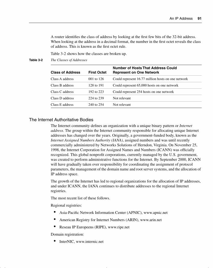
An IP Address 91
A router identifies the class of address by looking at the first few bits of the 32-bit address. When looking at the address in a decimal format, the number in the first octet reveals the class of address. This is known as the first octet rule.
Table 3-2 shows how the classes are broken up.
The Internet Authoritative BodiesThe Internet community defines an organization with a unique binary pattern or Internet address. The group within the Internet community responsible for allocating unique Internet addresses has changed over the years. Originally, a government-funded body, known as the Internet Assigned Numbers Authority (IANA), assigned numbers and was until recently commercially administered by Networks Solutions of Herndon, Virginia. On November 25, 1998, the Internet Corporation for Assigned Names and Numbers (ICANN) was officially recognized. This global nonprofit corporations, currently managed by the U.S. government, was created to perform administrative functions for the Internet. By September 2000, ICANN will have gradually taken over responsibility for coordinating the assignment of protocol parameters, the management of the domain name and root server systems, and the allocation of IP address space.
The growth of the Internet has led to regional organizations for the allocation of IP addresses, and under ICANN, the IANA continues to distribute addresses to the regional Internet registries.
The most recent list of these follows.
Regional registries:
• Asia-Pacific Network Information Center (APNIC), www.apnic.net
• American Registry for Internet Numbers (ARIN), www.arin.net
• Reseau IP Europeens (RIPE), www.ripe.net
Domain registration:
• InterNIC, www.internic.net
Table 3-2 The Classes of Addresses
Class of Address First OctetNumber of Hosts That Address Could Represent on One Network
Class A address 001 to 126 Could represent 16.77 million hosts on one network
Class B address 128 to 191 Could represent 65,000 hosts on one network
Class C address 192 to 223 Could represent 254 hosts on one network
Class D address 224 to 239 Not relevant
Class E address 240 to 254 Not relevant
chpt_01.book Page 91 Thursday, December 21, 2000 6:22 PM

92 Chapter 3: IP Addressing
When it has possession of the Internet address, an organization is responsible for determining where to place the boundary between network and host and is responsible for addressing the network. This is a complex task, which is an exercise in network design.
After the placement of the boundary between network and host is decided, this boundary is conveyed to Layer 3 devices in the network via the subnet mask.
An Example of Bit Allocation in a Network AddressIf 10 bits are allocated to the network portion of the address, 22 bits are left to the host portion of the address. In binary, 10 bits can be used to represent 1024 distinct entities (each being assigned a unique bit pattern or address). The 22 bits left to identify hosts can be used to represent four million hosts (actually, 4,194,304) on each network.
The total number of devices that can be addressed is calculated by multiplying the number of hosts’ addresses available on each network by the number of networks that can be addressed, as follows:
4,194,304 × 1,024 = 4,294,967,296
However, the administrator does not have the whole 32 bits to use. The Internet community, which manages the addresses to ensure their uniqueness, allocates a unique bit pattern to each organization that requests a connection to the Internet. This bit pattern is then used to uniquely identify the organization within the Internet.
The Subnet MaskThe subnet mask is used to extract the network portion of the address. The network address is needed by the Layer 3 devices to make routing decisions, as explained in Chapter 4, “IP Routing Principles.” Remember that in IP, the boundary between the network and the hosts is not rigid.
Where to Place the Network BoundaryThe number of networks required relative to the number of hosts per network determines the placement of the network boundary. This determination defines the respective number of bits allocated to both the network and the host portion of the address. This information must be conveyed to the Layer 3 devices (routers), which make decisions based on their tables that state where the network boundary lies. The subnet mask is the method of conveying the network boundary to end systems and network devices.
chpt_01.book Page 92 Thursday, December 21, 2000 6:22 PM
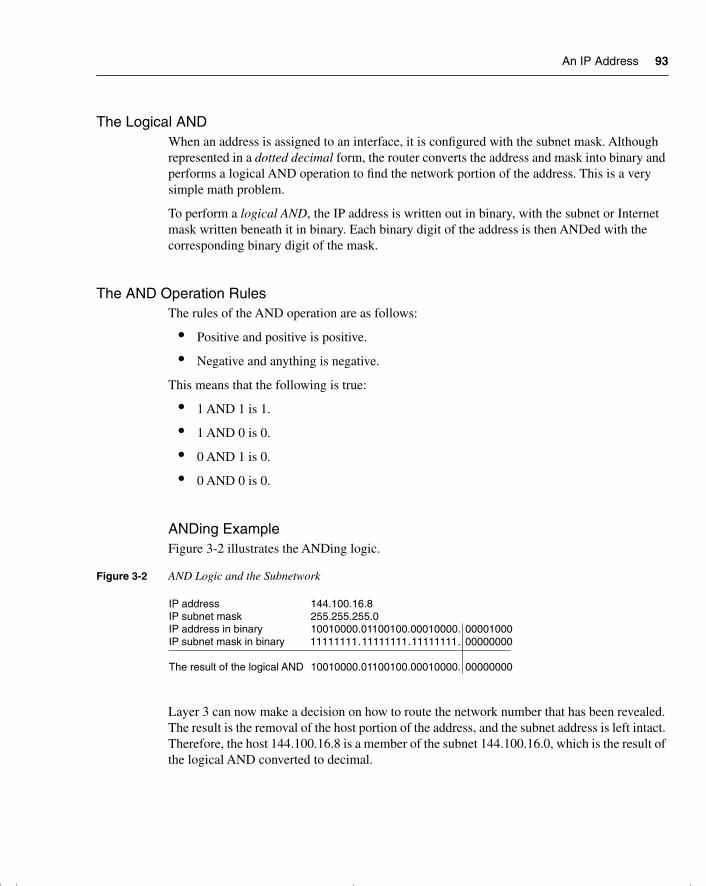
An IP Address 93
The Logical ANDWhen an address is assigned to an interface, it is configured with the subnet mask. Although represented in a dotted decimal form, the router converts the address and mask into binary and performs a logical AND operation to find the network portion of the address. This is a very simple math problem.
To perform a logical AND, the IP address is written out in binary, with the subnet or Internet mask written beneath it in binary. Each binary digit of the address is then ANDed with the corresponding binary digit of the mask.
The AND Operation RulesThe rules of the AND operation are as follows:
• Positive and positive is positive.
• Negative and anything is negative.
This means that the following is true:
• 1 AND 1 is 1.
• 1 AND 0 is 0.
• 0 AND 1 is 0.
• 0 AND 0 is 0.
ANDing ExampleFigure 3-2 illustrates the ANDing logic.
Figure 3-2 AND Logic and the Subnetwork
Layer 3 can now make a decision on how to route the network number that has been revealed. The result is the removal of the host portion of the address, and the subnet address is left intact. Therefore, the host 144.100.16.8 is a member of the subnet 144.100.16.0, which is the result of the logical AND converted to decimal.
IP address 144.100.16.8IP subnet mask 255.255.255.0IP address in binary 10010000.01100100.00010000. 00001000IP subnet mask in binary 11111111.11111111.11111111. 00000000
The result of the logical AND 10010000.01100100.00010000. 00000000
chpt_01.book Page 93 Thursday, December 21, 2000 6:22 PM
94 Chapter 3: IP Addressing
With this information, the router can now perform a search on the routing table to see whether it can route to the remote network. Therefore, the correct mask is essential to ensure that traffic can be directed through the overall network.
NOTE Again, the terms used to describe the mask are numerous and often vague. This book uses the term subnet mask when referring to the mask used within an organization, and it uses Internet mask or prefix mask when referring to the address allocated by ARIN.
When determining the subnet mask, certain rules must be followed. RFC 950 outlines these rules.
Familiar Rules in IP SubnettingBecause originally the routing protocols could not send the mask with the routing update, the first set of rules about applying IP addresses were different than they are now. For the most part, these rules still hold true. With the advent of new technology, however, it is now possible to surmount some of the previous limitations set out in RFC 950.
The earlier (and perhaps familiar) rules included the following:
• The network bits do not need to be contiguous, although they are advised to be contiguous.
• The network bits must not be all zeros or ones.
• The decision on the number of bits allocated to the network is made once per NIC number.
Reasons for the Familiar RulesBecause the original routing protocols did not send the subnet mask with the routing update, each router that received a subnet entry had to make some assumptions. The router assumed that the mask in use for the received subnet was the same as the one configured on its system.
If the subnet received in the routing update was of a different NIC address (it was not configured on one of the router’s interfaces), the router resolved the network address to the class address. The class of network was determined by the first octet rule.
New technology means that routing protocols can now send the subnet mask with the routing update. Therefore, the earlier rules regarding network classes do not necessarily apply.
chpt_01.book Page 94 Thursday, December 21, 2000 6:22 PM
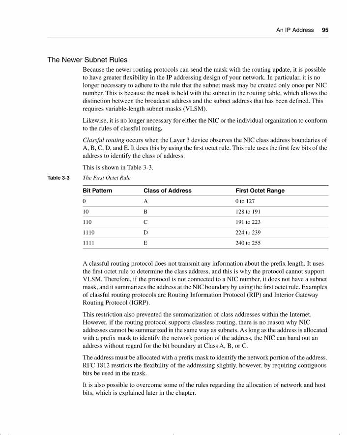
An IP Address 95
The Newer Subnet RulesBecause the newer routing protocols can send the mask with the routing update, it is possible to have greater flexibility in the IP addressing design of your network. In particular, it is no longer necessary to adhere to the rule that the subnet mask may be created only once per NIC number. This is because the mask is held with the subnet in the routing table, which allows the distinction between the broadcast address and the subnet address that has been defined. This requires variable-length subnet masks (VLSM).
Likewise, it is no longer necessary for either the NIC or the individual organization to conform to the rules of classful routing.
Classful routing occurs when the Layer 3 device observes the NIC class address boundaries of A, B, C, D, and E. It does this by using the first octet rule. This rule uses the first few bits of the address to identify the class of address.
This is shown in Table 3-3.
A classful routing protocol does not transmit any information about the prefix length. It uses the first octet rule to determine the class address, and this is why the protocol cannot support VLSM. Therefore, if the protocol is not connected to a NIC number, it does not have a subnet mask, and it summarizes the address at the NIC boundary by using the first octet rule. Examples of classful routing protocols are Routing Information Protocol (RIP) and Interior Gateway Routing Protocol (IGRP).
This restriction also prevented the summarization of class addresses within the Internet. However, if the routing protocol supports classless routing, there is no reason why NIC addresses cannot be summarized in the same way as subnets. As long as the address is allocated with a prefix mask to identify the network portion of the address, the NIC can hand out an address without regard for the bit boundary at Class A, B, or C.
The address must be allocated with a prefix mask to identify the network portion of the address. RFC 1812 restricts the flexibility of the addressing slightly, however, by requiring contiguous bits be used in the mask.
It is also possible to overcome some of the rules regarding the allocation of network and host bits, which is explained later in the chapter.
Table 3-3 The First Octet Rule
Bit Pattern Class of Address First Octet Range
0 A 0 to 127
10 B 128 to 191
110 C 191 to 223
1110 D 224 to 239
1111 E 240 to 255
chpt_01.book Page 95 Thursday, December 21, 2000 6:22 PM
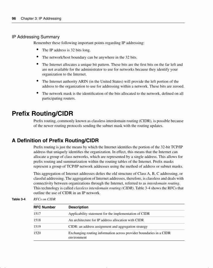
96 Chapter 3: IP Addressing
IP Addressing SummaryRemember these following important points regarding IP addressing:
• The IP address is 32 bits long.
• The network/host boundary can be anywhere in the 32 bits.
• The Internet allocates a unique bit pattern. These bits are the first bits on the far left and are not available for the administrator to use for networks because they identify your organization to the Internet.
• The Internet authority ARIN (in the United States) will provide the left portion of the address to the organization to use for addressing within a network. These bits are zeroed.
• The network mask is the identification of the bits allocated to the network, defined on all participating routers.
Prefix Routing/CIDRPrefix routing, commonly known as classless interdomain routing (CIDR), is possible because of the newer routing protocols sending the subnet mask with the routing updates.
A Definition of Prefix Routing/CIDRPrefix routing is just the means by which the Internet identifies the portion of the 32-bit TCP/IP address that uniquely identifies the organization. In effect, this means that the Internet can allocate a group of class networks, which are represented by a single address. This allows for prefix routing and summarization within the routing tables of the Internet. Prefix masks represent a group of TCP/IP network addresses using the method of address or subnet masks.
This aggregation of Internet addresses defies the old structure of Class A, B, C addressing, or classful addressing. The aggregation of Internet addresses, therefore, is classless and deals with connectivity between organizations through the Internet, referred to as interdomain routing. This technology is called classless interdomain routing (CIDR). Table 3-4 shows the RFCs that outline the use of CIDR in an IP network.
Table 3-4 RFCs on CIDR
RFC Number Description
1517 Applicability statement for the implementation of CIDR
1518 An architecture for IP address allocation with CIDR
1519 CIDR: an address assignment and aggregation strategy
1520 Exchanging routing information across provider boundaries in a CIDR environment
chpt_01.book Page 96 Thursday, December 21, 2000 6:22 PM
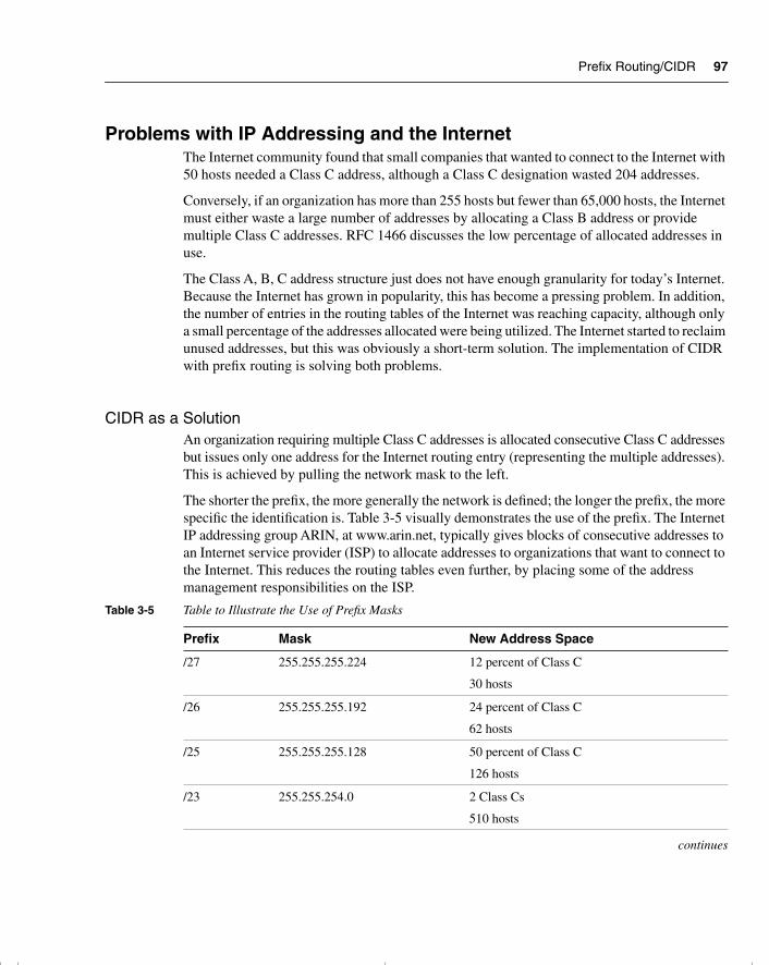
Prefix Routing/CIDR 97
Problems with IP Addressing and the InternetThe Internet community found that small companies that wanted to connect to the Internet with 50 hosts needed a Class C address, although a Class C designation wasted 204 addresses.
Conversely, if an organization has more than 255 hosts but fewer than 65,000 hosts, the Internet must either waste a large number of addresses by allocating a Class B address or provide multiple Class C addresses. RFC 1466 discusses the low percentage of allocated addresses in use.
The Class A, B, C address structure just does not have enough granularity for today’s Internet. Because the Internet has grown in popularity, this has become a pressing problem. In addition, the number of entries in the routing tables of the Internet was reaching capacity, although only a small percentage of the addresses allocated were being utilized. The Internet started to reclaim unused addresses, but this was obviously a short-term solution. The implementation of CIDR with prefix routing is solving both problems.
CIDR as a SolutionAn organization requiring multiple Class C addresses is allocated consecutive Class C addresses but issues only one address for the Internet routing entry (representing the multiple addresses). This is achieved by pulling the network mask to the left.
The shorter the prefix, the more generally the network is defined; the longer the prefix, the more specific the identification is. Table 3-5 visually demonstrates the use of the prefix. The Internet IP addressing group ARIN, at www.arin.net, typically gives blocks of consecutive addresses to an Internet service provider (ISP) to allocate addresses to organizations that want to connect to the Internet. This reduces the routing tables even further, by placing some of the address management responsibilities on the ISP.
Table 3-5 Table to Illustrate the Use of Prefix Masks
Prefix Mask New Address Space
/27 255.255.255.224 12 percent of Class C
30 hosts
/26 255.255.255.192 24 percent of Class C
62 hosts
/25 255.255.255.128 50 percent of Class C
126 hosts
/23 255.255.254.0 2 Class Cs
510 hosts
continues
chpt_01.book Page 97 Thursday, December 21, 2000 6:22 PM
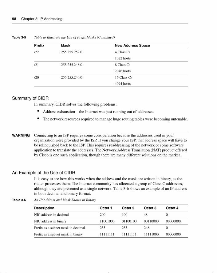
98 Chapter 3: IP Addressing
Summary of CIDRIn summary, CIDR solves the following problems:
• Address exhaustion—the Internet was just running out of addresses.
• The network resources required to manage huge routing tables were becoming untenable.
WARNING Connecting to an ISP requires some consideration because the addresses used in your organization were provided by the ISP. If you change your ISP, that address space will have to be relinquished back to the ISP. This requires readdressing of the network or some software application to translate the addresses. The Network Address Translation (NAT) product offered by Cisco is one such application, though there are many different solutions on the market.
An Example of the Use of CIDRIt is easy to see how this works when the address and the mask are written in binary, as the router processes them. The Internet community has allocated a group of Class C addresses, although they are presented as a single network. Table 3-6 shows an example of an IP address in both decimal and binary format.
/22 255.255.252.0 4 Class Cs
1022 hosts
/21 255.255.248.0 8 Class Cs
2046 hosts
/20 255.255.240.0 16 Class Cs
4094 hosts
Table 3-6 An IP Address and Mask Shown in Binary
Description Octet 1 Octet 2 Octet 3 Octet 4
NIC address in decimal 200 100 48 0
NIC address in binary 11001000 01100100 00110000 00000000
Prefix as a subnet mask in decimal 255 255 248 0
Prefix as a subnet mask in binary 11111111 11111111 11111000 00000000
Table 3-5 Table to Illustrate the Use of Prefix Masks (Continued)
Prefix Mask New Address Space
chpt_01.book Page 98 Thursday, December 21, 2000 6:22 PM
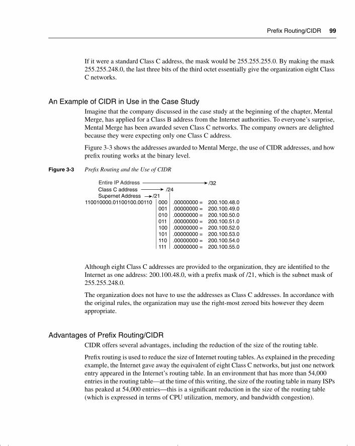
Prefix Routing/CIDR 99
If it were a standard Class C address, the mask would be 255.255.255.0. By making the mask 255.255.248.0, the last three bits of the third octet essentially give the organization eight Class C networks.
An Example of CIDR in Use in the Case StudyImagine that the company discussed in the case study at the beginning of the chapter, Mental Merge, has applied for a Class B address from the Internet authorities. To everyone’s surprise, Mental Merge has been awarded seven Class C networks. The company owners are delighted because they were expecting only one Class C address.
Figure 3-3 shows the addresses awarded to Mental Merge, the use of CIDR addresses, and how prefix routing works at the binary level.
Figure 3-3 Prefix Routing and the Use of CIDR
Although eight Class C addresses are provided to the organization, they are identified to the Internet as one address: 200.100.48.0, with a prefix mask of /21, which is the subnet mask of 255.255.248.0.
The organization does not have to use the addresses as Class C addresses. In accordance with the original rules, the organization may use the right-most zeroed bits however they deem appropriate.
Advantages of Prefix Routing/CIDRCIDR offers several advantages, including the reduction of the size of the routing table.
Prefix routing is used to reduce the size of Internet routing tables. As explained in the preceding example, the Internet gave away the equivalent of eight Class C networks, but just one network entry appeared in the Internet’s routing table. In an environment that has more than 54,000 entries in the routing table—at the time of this writing, the size of the routing table in many ISPs has peaked at 54,000 entries—this is a significant reduction in the size of the routing table (which is expressed in terms of CPU utilization, memory, and bandwidth congestion).
Class C addressSupernet Address /21
110010000.01100100.00110 000 .00000000 = 200.100.48.0001 .00000000 = 200.100.49.0010 .00000000 = 200.100.50.0011 .00000000 = 200.100.51.0100 .00000000 = 200.100.52.0101 .00000000 = 200.100.53.0110 .00000000 = 200.100.54.0111 .00000000 = 200.100.55.0
/24/32Entire IP Address
chpt_01.book Page 99 Thursday, December 21, 2000 6:22 PM
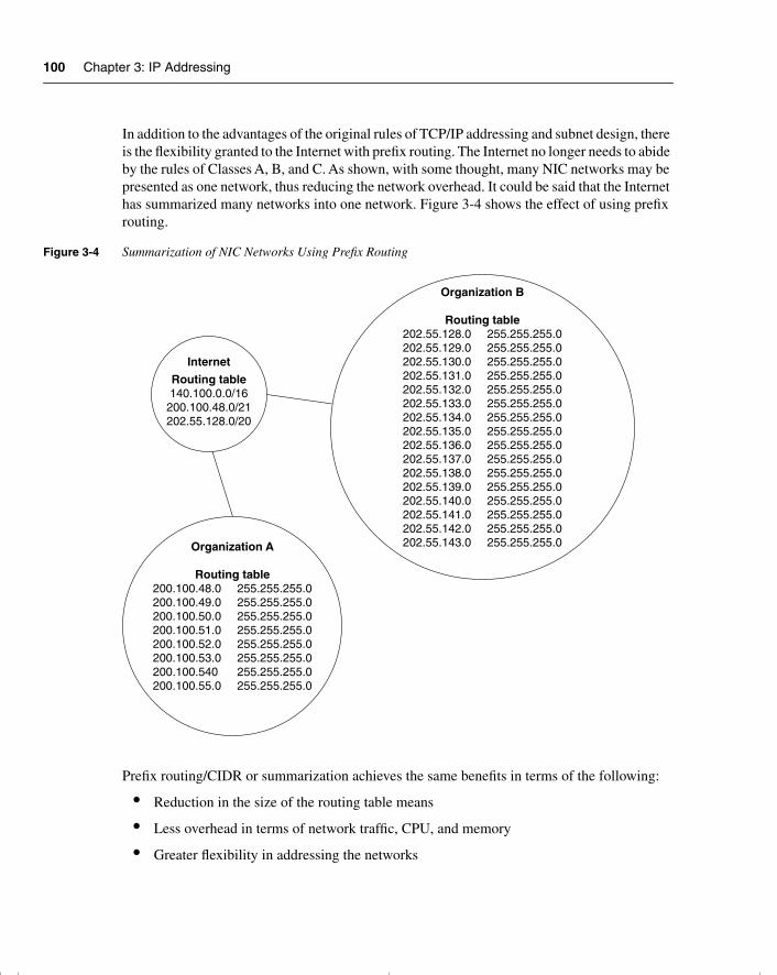
100 Chapter 3: IP Addressing
In addition to the advantages of the original rules of TCP/IP addressing and subnet design, there is the flexibility granted to the Internet with prefix routing. The Internet no longer needs to abide by the rules of Classes A, B, and C. As shown, with some thought, many NIC networks may be presented as one network, thus reducing the network overhead. It could be said that the Internet has summarized many networks into one network. Figure 3-4 shows the effect of using prefix routing.
Figure 3-4 Summarization of NIC Networks Using Prefix Routing
Prefix routing/CIDR or summarization achieves the same benefits in terms of the following:
• Reduction in the size of the routing table means
• Less overhead in terms of network traffic, CPU, and memory
• Greater flexibility in addressing the networks
Internet
Routing table140.100.0.0/16
200.100.48.0/21202.55.128.0/20
Organization A
Routing table200.100.48.0 255.255.255.0200.100.49.0 255.255.255.0200.100.50.0 255.255.255.0200.100.51.0 255.255.255.0200.100.52.0 255.255.255.0200.100.53.0 255.255.255.0200.100.540 255.255.255.0200.100.55.0 255.255.255.0
Organization B
Routing table202.55.128.0 255.255.255.0202.55.129.0 255.255.255.0202.55.130.0 255.255.255.0202.55.131.0 255.255.255.0202.55.132.0 255.255.255.0202.55.133.0 255.255.255.0202.55.134.0 255.255.255.0202.55.135.0 255.255.255.0202.55.136.0 255.255.255.0202.55.137.0 255.255.255.0202.55.138.0 255.255.255.0202.55.139.0 255.255.255.0202.55.140.0 255.255.255.0202.55.141.0 255.255.255.0202.55.142.0 255.255.255.0202.55.143.0 255.255.255.0
chpt_01.book Page 100 Thursday, December 21, 2000 6:22 PM
Variable-Length Subnet Masks 101
An organization can use summarization for the same reason as the Internet uses it with prefix routing: to reduce network overhead. The length of the prefix in this case depends on the number of bits needed rather than the Class A, B, and C structure.
NOTE The bit pattern provided by the Internet cannot be altered. The bits to the right of the unique address given by the Internet are at the disposal of the organization.
To utilize the power of summarization within an organization, a sophisticated routing protocol that sends the mask with the routing updates is required. The capability to move the network/host boundary is called VLSM.
Variable-Length Subnet MasksVariable-length subnet mask (VLSM) is used within an organization instead of CIDR, which is used within the Internet. VLSMs enable you to allocate required host bits on a granular basis.
Because organizations are rarely uniform in the distribution of hosts, it is much more efficient to provide only those hosts bits to address the number of hosts on a particular network.
An Example of VLSMConsider that Mental Merge has been given a Class B address. The company has grown and now has some satellite offices that connect via point-to-point serial lines. The remote offices have eight workstations, three printers, and a router connecting them to the outside world. The main site has a building with ten floors, and each floor has approximately 25 workstations and four printers. A server farm in the basement has three servers and two routers. In this scenario, it is impossible to create a mask that serves all these environments. If you use an older routing protocol, you will waste a considerable amount of the available address space.
VLSM requires a routing protocol that supports the sending of the subnet mask.
Routing Protocols That Support VLSMThe following routing protocols support VLSM:
• RIPv2
• OSPF
• IS-IS
• EIGRP
• BGP-4
chpt_01.book Page 101 Thursday, December 21, 2000 6:22 PM
102 Chapter 3: IP Addressing
NOTE Static routes could be said to use VLSM. They are often used to redistribute between routing protocols sharing a NIC number when one routing protocol supports VLSM and the other does not. In these instances, the static route will define one summarized route for the non-VLSM routing protocol. This technique is also used when redistributing into BGP-4.
The following routing protocols do not support VLSM:
• RIPv1
• IGRP
• EGP
Rules for VLSMThe rules for variably subnetting an IP address are remarkably straightforward. The key is to remember that a hierarchical design in the addressing scheme is the goal. The physical network design also must reflect this logical hierarchy (as discussed in Chapter 2, “Managing Scalable Network Growth”). After the physical design is mapped, the logical structure can be placed on top of it.
The following rules apply when subnetting:
• A subnet can be used to address hosts, or it can be used for further subnetting.
• Within the allocation of subsequent subnets, the rule of not using all zeros or ones does not apply.
• The routing protocol must carry the subnet mask in its updates.
• Multiple IP addresses intended to be summarized must have the same high-order bits.
• Routing decisions are made on the entire address, and the router goes from more specific to more general when making routing decisions.
The Advantages of Using VLSMThe two main reasons for using VLSM are as follows:
• To make efficient use of the available addressing
• To enforce a good hierarchical design, allowing summarization and documentation
Figure 3-5 illustrates the use of VLSM for summarization and documentation.
chpt_01.book Page 102 Thursday, December 21, 2000 6:22 PM
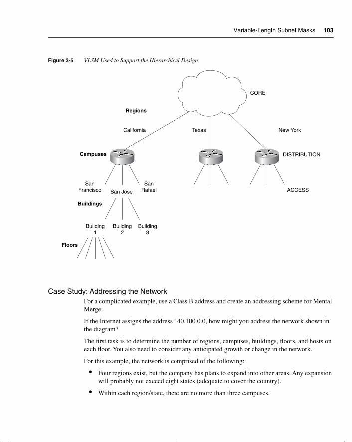
Variable-Length Subnet Masks 103
Figure 3-5 VLSM Used to Support the Hierarchical Design
Case Study: Addressing the NetworkFor a complicated example, use a Class B address and create an addressing scheme for Mental Merge.
If the Internet assigns the address 140.100.0.0, how might you address the network shown in the diagram?
The first task is to determine the number of regions, campuses, buildings, floors, and hosts on each floor. You also need to consider any anticipated growth or change in the network.
For this example, the network is comprised of the following:
• Four regions exist, but the company has plans to expand into other areas. Any expansion will probably not exceed eight states (adequate to cover the country).
• Within each region/state, there are no more than three campuses.
CORE
Regions
California Texas New York
DISTRIBUTION
ACCESS
Campuses
SanFrancisco
SanRafaelSan Jose
Buildings
Floors
Building1
Building2
Building3
chpt_01.book Page 103 Thursday, December 21, 2000 6:22 PM
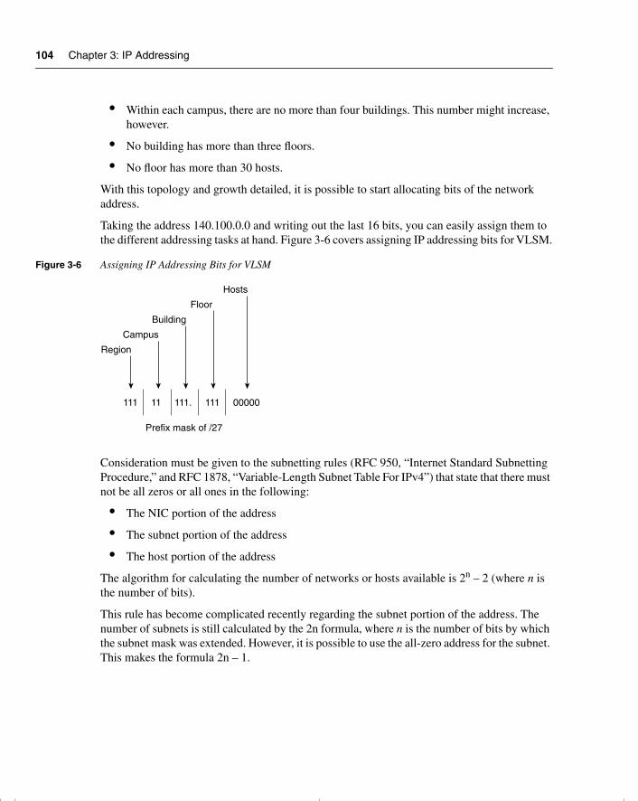
104 Chapter 3: IP Addressing
• Within each campus, there are no more than four buildings. This number might increase, however.
• No building has more than three floors.
• No floor has more than 30 hosts.
With this topology and growth detailed, it is possible to start allocating bits of the network address.
Taking the address 140.100.0.0 and writing out the last 16 bits, you can easily assign them to the different addressing tasks at hand. Figure 3-6 covers assigning IP addressing bits for VLSM.
Figure 3-6 Assigning IP Addressing Bits for VLSM
Consideration must be given to the subnetting rules (RFC 950, “Internet Standard Subnetting Procedure,” and RFC 1878, “Variable-Length Subnet Table For IPv4”) that state that there must not be all zeros or all ones in the following:
• The NIC portion of the address
• The subnet portion of the address
• The host portion of the address
The algorithm for calculating the number of networks or hosts available is 2n – 2 (where n is the number of bits).
This rule has become complicated recently regarding the subnet portion of the address. The number of subnets is still calculated by the 2n formula, where n is the number of bits by which the subnet mask was extended. However, it is possible to use the all-zero address for the subnet. This makes the formula 2n – 1.
111 11 111. 111 00000
Region
Campus
Building
Floor
Hosts
Prefix mask of /27
chpt_01.book Page 104 Thursday, December 21, 2000 6:22 PM
Variable-Length Subnet Masks 105
WARNING Although Cisco provides the utility of subnet zero, this command should be used only with full understanding of the network devices and the knowledge that there is no device that uses the zero broadcast. Even today, some systems, such as Sun Solaris 4.x, have problems using subnet zero even with OSPF.
The command to enable the use of the zero subnet became the default configuration in version 12.0 of the Cisco IOS.
Although the 2n – 2 rule is still true for the NIC portion of the address, it is not of concern. This is because the NIC portion of the address is out of your control because it was defined by the Internet.
However, attention must still be given to the host portion of the address. The host portion of the address must conform to the subnet rule as defined; otherwise, it is not possible for the router to distinguish between hosts and broadcast addresses. The host cannot use an IP address of all zeros in the subnet address or all ones in the subnet broadcast address. The all-zeros address is used to show the subnet delimiter.
Bit Allocation, the Subnet Rule, and VLSMIn truth, the subnet does have to conform to the rule as described. With VLSM, however, it is often forgotten that the entire subnet area is considered one subnet. Therefore, the rule must be obeyed once, not on each instance of variable subnetting.
In the preceding example, you would choose to obey the rule either in the bits allocated to the region, campus, or building, but not in each hierarchical layer. It would make most sense to adhere to the rule using the least-significant bits. In this case, three bits have been allocated to the access layer, enabling you to identify eight floors. You have no more than three floors to address in any building, however. Obeying the rule on this layer makes sense because you reduce the floors that may be addressed to six, which is still twice as many as required.
Allocating VLSM AddressesApplying the addressing scheme designed in the preceding example is very simple after the design has been worked out.
Taking the region of California as the example to address, you will now address the entire region.
Figure 3-7 shows the bit allocation that was determined.
chpt_01.book Page 105 Thursday, December 21, 2000 6:22 PM
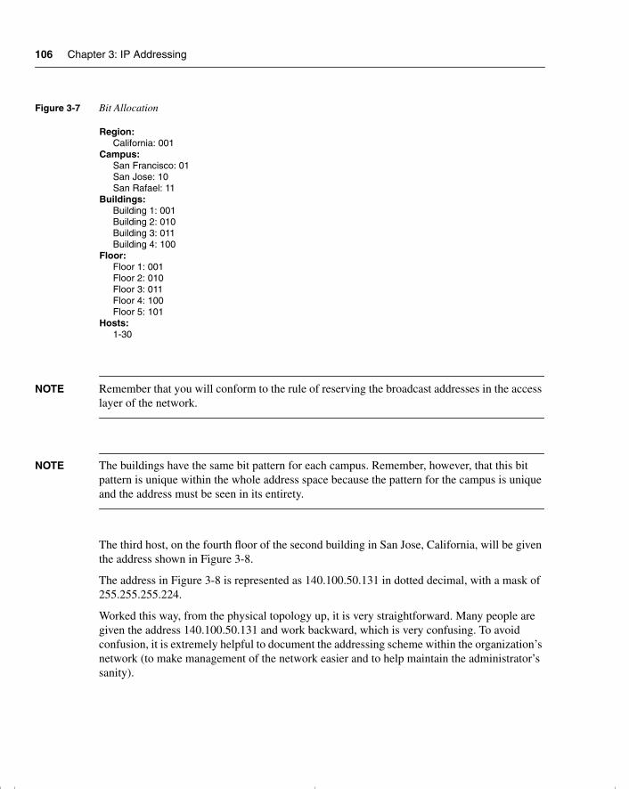
106 Chapter 3: IP Addressing
Figure 3-7 Bit Allocation
NOTE Remember that you will conform to the rule of reserving the broadcast addresses in the access layer of the network.
NOTE The buildings have the same bit pattern for each campus. Remember, however, that this bit pattern is unique within the whole address space because the pattern for the campus is unique and the address must be seen in its entirety.
The third host, on the fourth floor of the second building in San Jose, California, will be given the address shown in Figure 3-8.
The address in Figure 3-8 is represented as 140.100.50.131 in dotted decimal, with a mask of 255.255.255.224.
Worked this way, from the physical topology up, it is very straightforward. Many people are given the address 140.100.50.131 and work backward, which is very confusing. To avoid confusion, it is extremely helpful to document the addressing scheme within the organization’s network (to make management of the network easier and to help maintain the administrator’s sanity).
Region:California: 001
Campus:San Francisco: 01San Jose: 10San Rafael: 11
Buildings:Building 1: 001Building 2: 010Building 3: 011Building 4: 100
Floor:Floor 1: 001Floor 2: 010Floor 3: 011Floor 4: 100Floor 5: 101
Hosts:1-30
chpt_01.book Page 106 Thursday, December 21, 2000 6:22 PM
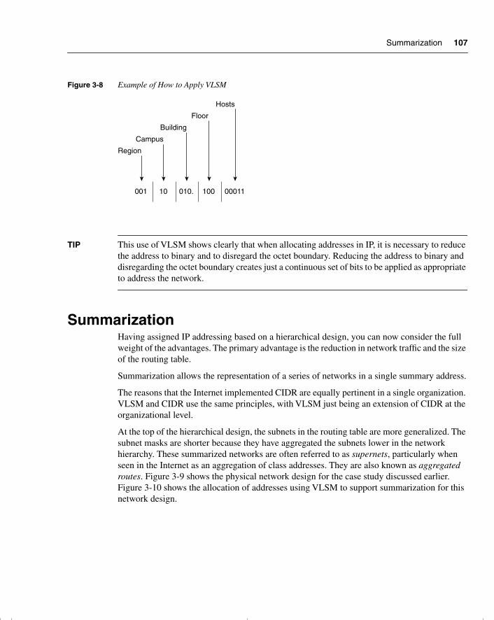
Summarization 107
Figure 3-8 Example of How to Apply VLSM
TIP This use of VLSM shows clearly that when allocating addresses in IP, it is necessary to reduce the address to binary and to disregard the octet boundary. Reducing the address to binary and disregarding the octet boundary creates just a continuous set of bits to be applied as appropriate to address the network.
SummarizationHaving assigned IP addressing based on a hierarchical design, you can now consider the full weight of the advantages. The primary advantage is the reduction in network traffic and the size of the routing table.
Summarization allows the representation of a series of networks in a single summary address.
The reasons that the Internet implemented CIDR are equally pertinent in a single organization. VLSM and CIDR use the same principles, with VLSM just being an extension of CIDR at the organizational level.
At the top of the hierarchical design, the subnets in the routing table are more generalized. The subnet masks are shorter because they have aggregated the subnets lower in the network hierarchy. These summarized networks are often referred to as supernets, particularly when seen in the Internet as an aggregation of class addresses. They are also known as aggregated routes. Figure 3-9 shows the physical network design for the case study discussed earlier. Figure 3-10 shows the allocation of addresses using VLSM to support summarization for this network design.
001 10 010. 100 00011
Region
Campus
Building
Floor
Hosts
chpt_01.book Page 107 Thursday, December 21, 2000 6:22 PM
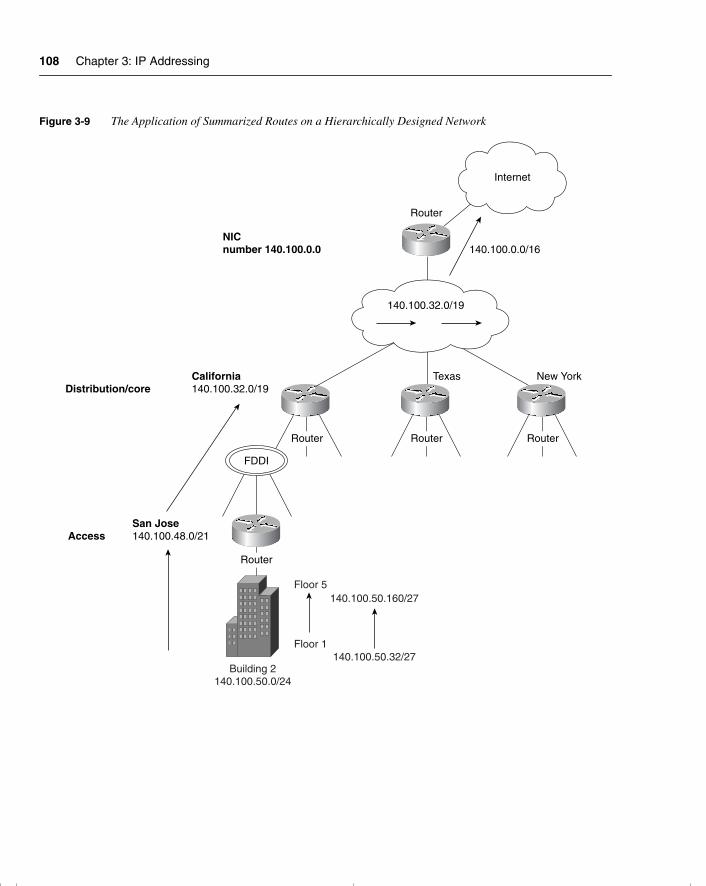
108 Chapter 3: IP Addressing
Figure 3-9 The Application of Summarized Routes on a Hierarchically Designed Network
Router
Internet
Distribution/core
Access
RouterRouter
Router
Router
140.100.32.0/19
NICnumber 140.100.0.0 140.100.0.0/16
Texas New YorkCalifornia140.100.32.0/19
San Jose140.100.48.0/21
Building 2140.100.50.0/24
Floor 5
Floor 1
140.100.50.160/27
140.100.50.32/27
FDDI
chpt_01.book Page 108 Thursday, December 21, 2000 6:22 PM
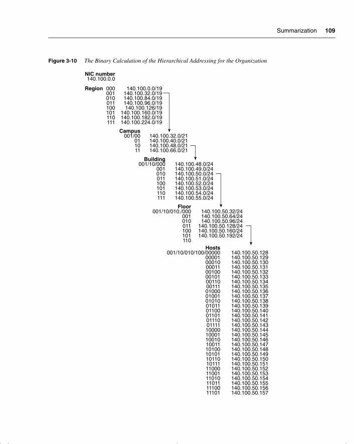
Summarization 109
Figure 3-10 The Binary Calculation of the Hierarchical Addressing for the Organization
NIC number140.100.0.0
Region 000 140.100.0.0/19001 140.100.32.0/19010 140.100.84.0/19011 140.100.96.0/19100 140.100.126/19101 140.100.160.0/19110 140.100.182.0/19111 140.100.224.0/19
Campus001/00 140.100.32.0/21
01 140.100.40.0/2110 140.100.48.0/2111 140.100.66.0/21
Building001/10/000 140.100.48.0/24
001 140.100.49.0/24010 140.100.50.0/24011 140.100.51.0/24100 140.100.52.0/24101 140.100.53.0/24110 140.100.54.0/24111 140.100.55.0/24
Floor001/10/010./000 140.100.50.32/24
001 140.100.50.64/24010 140.100.50.96/24011 140.100.50.128/24100 140.100.50.160/24101 140.100.50.192/24110
Hosts001/10/010/100/00000 140.100.50.128
00001 140.100.50.12900010 140.100.50.13000011 140.100.50.13100100 140.100.50.13200101 140.100.50.13300110 140.100.50.13400111 140.100.50.13501000 140.100.50.13601001 140.100.50.13701010 140.100.50.13801011 140.100.50.13901100 140.100.50.14001101 140.100.50.14101110 140.100.50.14201111 140.100.50.14310000 140.100.50.14410001 140.100.50.14510010 140.100.50.14610011 140.100.50.14710100 140.100.50.14810101 140.100.50.14910110 140.100.50.15010111 140.100.50.15111000 140.100.50.15211001 140.100.50.15311010 140.100.50.15411011 140.100.50.15511100 140.100.50.15611101 140.100.50.157
chpt_01.book Page 109 Thursday, December 21, 2000 6:22 PM
110 Chapter 3: IP Addressing
The Advantages of SummarizationThe capability to summarize multiple subnets within a few subnets has the advantages discussed in the next few sections.
Reducing the Size of the Routing TableIn reducing the size of the routing table, the updates are smaller, demanding less bandwidth from the network. A smaller routing table also requires less memory in the router or CPU in the routing process itself because the lookup is quicker and more efficient.
SimplificationThe recalculation of the network is also simplified by maintaining small routing tables.
Hiding Network ChangesIf the routing table contains a summary of the networks beneath it, any changes in the network at these levels are not seen. This is both a good thing and a bad thing. If the network in the earlier example—140.100.50.128/27, the subnet on the fourth floor of the second building in San Jose, California—were to go down, the router at the core would be oblivious to the LAN problem. This is beneficial because there are no additional updates or recalculation.
The disadvantage is that any traffic destined for that subnet is sent on the assumption that it exists. To be more accurate, the core router sees the inbound IP packet destined for 140.100.50.131 and, instead of applying the /27 mask, uses the mask that it has configured. It employs the /19 mask that sees the subnet 140.100.32.0/19, although in reality the destination subnet is 140.100.50.128/27. If the subnet 140.100.50.128 is no longer available, all traffic is still forwarded to the subnet until it reaches a router that holds the same mask as the IP packet and therefore is aware that it is no longer available. An ICMP message that the network is unreachable is generated to the transmitting host. The host may stop transmitting after hearing that the network is down.
Although unnecessary traffic will traverse the network for a while, it is a minor inconvenience compared to the routing update demands on the network and the CPU utilization on the routers in large networks.
Network GrowthSummarization allows networks to grow because the network overhead can scale.
chpt_01.book Page 110 Thursday, December 21, 2000 6:22 PM
Summarization 111
Other Solutions to Address ExhaustionThe use of the Cisco feature IP unnumbered is useful on the point-to-point serial lines because it saves the use of a subnet.
Cisco’s use of secondary addressing is useful because it provides two subnets to a physical interface—and, therefore, more available host bits. This does not save address space, but it is a solution for routing protocols that do not support VLSM. Unfortunately, there are some compatibility issues with other TCP/IP stacks—for example, not all OSPF routing protocols will see the second subnet.
Configuring SummarizationIn the newer routing protocols, summarization must be manually configured; this manual configuration lends greatly to its subtlety and strength. Each routing protocol deals with summarization in a slightly different way, and how summarization works or is configured depends on the routing protocol used. This is discussed in detail in Chapter 4.
NOTE Although Border Gateway Protocol (BGP) and Enhanced IGRP (EIGRP) perform automatic summarization, the summarization is done at the NIC boundary, using the first octet rule. This is the same as with older routing protocols such as RIP.
Automatic SummarizationAll routing protocols employ some level of summarization. The older protocols, such as RIP and IGRP, automatically summarize at the NIC or natural class boundary. They have no choice because the subnet mask is not sent in the routing updates. When a routing update is received, the router looks to see whether it has an interface in the same class network. If it has one, it applies the mask configured on the interface to the incoming routing update. With no interface configured in the same NIC network, there is insufficient information and the routing protocol uses the natural mask for the routing update. The first few bits in the address are used to determine to which class of address it belongs, and then the appropriate mask is applied. This is known as the first octet rule.
Manual SummarizationBoth EIGRP and Open Shortest Path First (OSPF) are more sophisticated: They send the subnet mask along with the routing update. This feature allows the use of VLSM and summarization. When the routing update is received, it assigns the mask to the particular subnet. When the
chpt_01.book Page 111 Thursday, December 21, 2000 6:22 PM
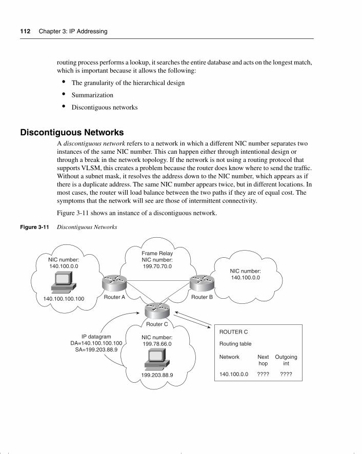
112 Chapter 3: IP Addressing
routing process performs a lookup, it searches the entire database and acts on the longest match, which is important because it allows the following:
• The granularity of the hierarchical design
• Summarization
• Discontiguous networks
Discontiguous NetworksA discontiguous network refers to a network in which a different NIC number separates two instances of the same NIC number. This can happen either through intentional design or through a break in the network topology. If the network is not using a routing protocol that supports VLSM, this creates a problem because the router does know where to send the traffic. Without a subnet mask, it resolves the address down to the NIC number, which appears as if there is a duplicate address. The same NIC number appears twice, but in different locations. In most cases, the router will load balance between the two paths if they are of equal cost. The symptoms that the network will see are those of intermittent connectivity.
Figure 3-11 shows an instance of a discontiguous network.
Figure 3-11 Discontiguous Networks
NIC number:140.100.0.0
140.100.100.100 Router A Router B
Router C
Frame RelayNIC number:199.70.70.0
IP datagramDA=140.100.100.100
SA=199.203.88.9
NIC number:199.78.66.0
NIC number:140.100.0.0
199.203.88.9
ROUTER C
Routing table
Network Nexthop
Outgoingint
140.100.0.0 ???? ????
chpt_01.book Page 112 Thursday, December 21, 2000 6:22 PM
Summarization 113
Considerations for Summarization with Discontiguous NetworksIf there are discontiguous networks in the organization, it is important that summarization is turned off or not configured. Summarization may not provide enough information to the routing table on the other side of the intervening NIC number to be capable of appropriately routing to the destination subnets. This is especially true of EIGRP, which automatically summarizes at the NIC boundary, which would be disastrous in this situation.
In OSPF and EIGRP, manual configuration is required for any sophistication in the network design. It is not always possible to achieve summarization because this depends entirely on the addressing scheme that has been deployed. However, because EIGRP can perform summarization at the interface level, it is possible to select interfaces that do not feed discontiguous networks for summarization. This capability to summarize selectively is very powerful.
The key to whether summarization is configurable is determined by whether there are common high-order bits in the addresses.
Case Study In the case study used earlier, the design immediately allows for summarization, as shown in the now familiar layout in Figure 3-8.
In this design, every campus within the same region will share the same high-order bits (those to the left). In California, every campus, building, floor, and host will share the bits 001. In this manner, every building in the San Jose campus will share the high-order bits of 00110. Therefore, it is very simple to configure summarization.
This is not necessarily the case if the addressing structure is already in place. Some analysis of the addressing scheme is required to decide whether summarization can be configured.
Alternatives to SummarizationIf summarization is deemed impossible, you have the following two options:
• Not to summarize and understand the scaling limitations that have now been set on the network.
• To readdress the network. This task is not to be underestimated, although the advantages may well make it worthwhile.
VLSM also enables you to allocate the required bits for addressing a particular network.
chpt_01.book Page 113 Thursday, December 21, 2000 6:22 PM
114 Chapter 3: IP Addressing
Optimizing the IP Address SpaceParticularly in the use of WANs, where there is a predominance of point-to-point connections, allocating an entire subnet is very wasteful. VLSM allows refinement of the address space to exactly that which is needed and no more.
As demonstrated, dealing with the use of VLSM to support the hierarchical design requires the consideration of the entire network topology. When using VLSM to optimize the IP address space, the network addressing can become extremely confused if it is not clearly managed and documented.
In the preceding example, no consideration was given to the connections between the regions, campuses, and buildings—all of which could be point-to-point lines.
Now it is important to consider the last part of the network addressing, which will illustrate the use of VLSM for IP address optimization.
Assigning IP VLSM Subnets for WAN ConnectionsOne common approach is to allocate a subnet that has not been assigned to hosts, and to variably subnet it for use with connectivity between rather than within areas.
In this case study, it is sensible to take a subnet from the bits allocated to the buildings. Because there are enough bits allocated to address eight buildings, you have twice as many subnets as required. Even with the possibility of growth, one subnet would not be missed. Because the building bits come after the bits assigned to the campus, a choice must be made as to which campus will be selected for the honor of contributing a subnet of WAN addressing. This is an arbitrary decision that needs to be documented. If necessary, a building subnet can be commandeered from each campus.
If possible, the subnet used should have nothing to do with any of the existing subnets. That is, there is a consistency in numbering that identifies the WAN links, so in a troubleshooting environment, you can immediately see that a WAN link is causing the trouble and will not confuse the subnet (VLSM) with an existing segment.
In this example, if you use the bit pattern 000 as the network address for the building section; in addition for the campus and the region, the third octet would result in a 0. The network address for all interconnectivity would be 140.100.0. . .. The last octet would be available for further subnetting with VLSM.
The subnet chosen for the WAN connections will be subnetted further using 30 bits of subnetting. This allows for only two connections and is therefore a very efficient mask for point-to-point links.
Remember that the rule for not using all zeros or all ones is based on the entire subnet, not on the octet boundary. Figure 3-12 shows assigning IP VLSM subnets for WAN connections.
chpt_01.book Page 114 Thursday, December 21, 2000 6:22 PM
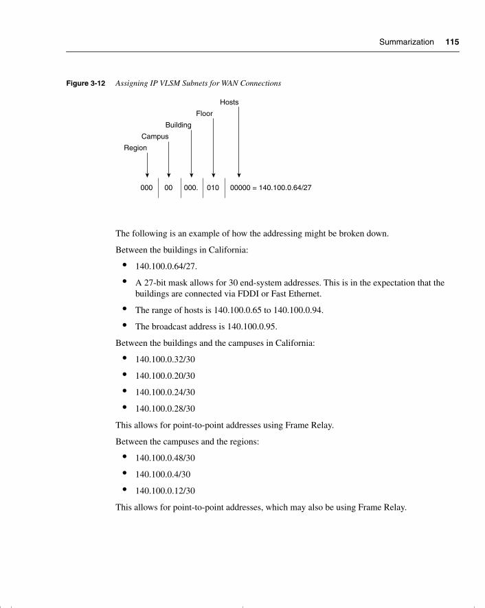
Summarization 115
Figure 3-12 Assigning IP VLSM Subnets for WAN Connections
The following is an example of how the addressing might be broken down.
Between the buildings in California:
• 140.100.0.64/27.
• A 27-bit mask allows for 30 end-system addresses. This is in the expectation that the buildings are connected via FDDI or Fast Ethernet.
• The range of hosts is 140.100.0.65 to 140.100.0.94.
• The broadcast address is 140.100.0.95.
Between the buildings and the campuses in California:
• 140.100.0.32/30
• 140.100.0.20/30
• 140.100.0.24/30
• 140.100.0.28/30
This allows for point-to-point addresses using Frame Relay.
Between the campuses and the regions:
• 140.100.0.48/30
• 140.100.0.4/30
• 140.100.0.12/30
This allows for point-to-point addresses, which may also be using Frame Relay.
000 00 000. 010 00000 = 140.100.0.64/27
Region
Campus
Building
Floor
Hosts
chpt_01.book Page 115 Thursday, December 21, 2000 6:22 PM
116 Chapter 3: IP Addressing
Between the regions:
• 140.100.0.96/30
• 140.100.0.16/30
• 140.100.0.8/30
This allows for point-to-point addresses, which may also be using Frame Relay or dedicated serial leased lines.
WARNING In the instance of a subnet being used to address WAN connections, it may not be possible to summarize these networks.
The rules and conditions for creating a valid and appropriate IP addressing scheme for the network are complicated. Among other things, the addressing scheme must allow for growth, to scale over time. What works today may not be flexible for next year’s business requirements. You cannot build a network that will accommodate every change and addition to its environment. With careful design, however, it may be possible to anticipate some of these changes and to ensure a network with enough flexibility to survive the changes.
Designing IP NetworksThe topics that make up the rest of this chapter are not in the Building Scalable Cisco Networks (BSCN) course, upon which the Routing exam is partially based. Therefore, these topics might not be on the exam, but they have been included in this chapter because they place the topic of IP addressing into a wider context. These subjects should be studied not with the intention of answering questions on the exam, but rather as information that extends the subject matter. There will be no questions in the end of the chapter quiz, nor references to this material in the scenarios.
This is important both for understanding the subject. It is also crucial for use within the context of the Cisco certification.
Much of the design principles for an IP network have been dealt with in a practical manner in the preceding section. This section, therefore, examines the design criteria from a high-level perspective.
Certain questions should be asked before applying IP addresses to end devices:
• How many subnets exist currently on your network?
• How many hosts exist on each network?
chpt_01.book Page 116 Thursday, December 21, 2000 6:22 PM
Designing IP Networks 117
• If the number of hosts varies on each subnet, how many hosts are there on the largest subnet and the smallest subnet? If there is an average number, this is also of interest.
• Where are these subnets in relation to the topology map of the network?
• In the next 3 to 12 months, how many more hosts will exist on each network?
• In the next 3 to 12 months, how many more networks will exist?
• How many subnets are available?
• If the network is short of address space, what must be done to make some available?
• Do you have a client/server environment?
• If so, where are the local servers located? On the same segment as the clients? On another segment and subnet?
• How much traffic is sent to the local servers?
• What is the nature of the traffic: high in volume, large packet size, sensitive to delay, bursty?
• Is access required from other subnets?
• If DHCP is used, where are the servers located?
• Are there any global resources that need to be accessed by everyone?
• If there are global resources on this subnet, is access required from other subnets?
• Do any security issues need to be considered?
• Are the clients mobile? Do they move around the campuses and require access from any location?
• Does the company require Internet access?
• If Internet access is required, for whom? Does this include e-mail, web browsing, remote access, or a web page for customers?
• Does your company have a NIC address from the Internet? If not, is it proposing to apply for one, or will it be connecting via an ISP?
• Is TCP/IP the only protocol on the network? If not, what are the other protocols, and is there any intention to tunnel these protocols through the WAN or core of the network using TCP/IP?
Not all of these questions may be pertinent to any particular organization. If this checklist is answered, however, the administrator or network design engineer will have a great deal of information with which to design the network. Although the questionnaire spans slightly more than the limited requirements for assigning IP addresses, the answers to these questions are crucial for the design of an IP network and in determining the traffic flow within the organization.
chpt_01.book Page 117 Thursday, December 21, 2000 6:22 PM
118 Chapter 3: IP Addressing
These questions should be considered against the topology map of the network. Without the support of the physical hierarchical design, it will not be possible to summarize the network traffic.
After the capacity of the network is understood, it is possible to design the addressing scheme. This will follow the same principles shown in the section “Allocating VLSM Addresses,” earlier in this chapter.
Certain guidelines or key points should be used in the VLSM design of the network. The following section identifies these guidelines.
Keys Points to Remember When Designing an IP NetworkThe following list of items should be addressed when preparing the IP addressing plan for your network:
• Identifying how many hosts and subnets will be required in the future requires communication with other departments in terms of the growth of personnel as well as the budget for network growth. Without the standard-issue crystal ball, a wider view must be taken at a high level to answer these questions, with the answers coming from a range of sources, including the senior management and executive team of the organization.
• The design of the IP network must take into consideration the network equipment and whether consideration should be given to different vendor equipment. Interoperability may well be an issue, particularly with some of the features offered by each product.
• For route aggregation (summarization) to occur, the address assignments must have topological significance.
• When using VLSM, the routing protocol must send the extended prefix (subnet mask) with the routing update.
• When using VLSM, the routing protocol must do a routing table lookup based on the longest match.
• Make certain that enough bits have been allowed for at each level of the hierarchical design to address all devices at that layer. Also be sure that growth of the network at each level has been anticipated. What address space is to be used (Class A, B, C, private, registered), and will it scale with the organization?
TIP Cisco offers many enhancements in its IOS. Most of these enhancements are interoperable. If they are not, they provide solutions for connecting to industry standards (which, of course, are fully supported by Cisco). Check with the Cisco web page (www.cisco.com) to review the latest features and any connectivity issues.
chpt_01.book Page 118 Thursday, December 21, 2000 6:22 PM
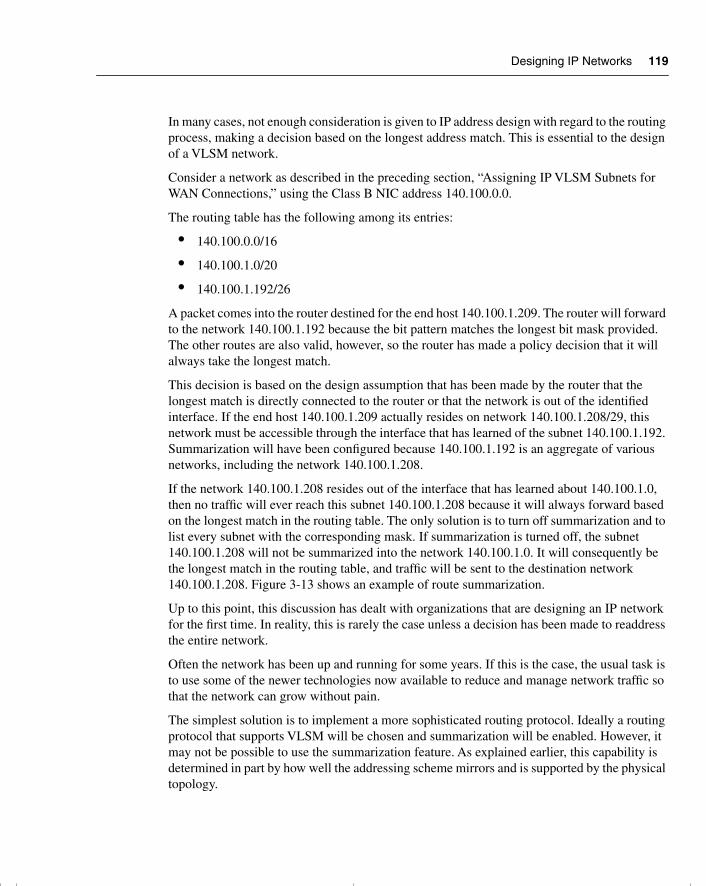
Designing IP Networks 119
In many cases, not enough consideration is given to IP address design with regard to the routing process, making a decision based on the longest address match. This is essential to the design of a VLSM network.
Consider a network as described in the preceding section, “Assigning IP VLSM Subnets for WAN Connections,” using the Class B NIC address 140.100.0.0.
The routing table has the following among its entries:
• 140.100.0.0/16
• 140.100.1.0/20
• 140.100.1.192/26
A packet comes into the router destined for the end host 140.100.1.209. The router will forward to the network 140.100.1.192 because the bit pattern matches the longest bit mask provided. The other routes are also valid, however, so the router has made a policy decision that it will always take the longest match.
This decision is based on the design assumption that has been made by the router that the longest match is directly connected to the router or that the network is out of the identified interface. If the end host 140.100.1.209 actually resides on network 140.100.1.208/29, this network must be accessible through the interface that has learned of the subnet 140.100.1.192. Summarization will have been configured because 140.100.1.192 is an aggregate of various networks, including the network 140.100.1.208.
If the network 140.100.1.208 resides out of the interface that has learned about 140.100.1.0, then no traffic will ever reach this subnet 140.100.1.208 because it will always forward based on the longest match in the routing table. The only solution is to turn off summarization and to list every subnet with the corresponding mask. If summarization is turned off, the subnet 140.100.1.208 will not be summarized into the network 140.100.1.0. It will consequently be the longest match in the routing table, and traffic will be sent to the destination network 140.100.1.208. Figure 3-13 shows an example of route summarization.
Up to this point, this discussion has dealt with organizations that are designing an IP network for the first time. In reality, this is rarely the case unless a decision has been made to readdress the entire network.
Often the network has been up and running for some years. If this is the case, the usual task is to use some of the newer technologies now available to reduce and manage network traffic so that the network can grow without pain.
The simplest solution is to implement a more sophisticated routing protocol. Ideally a routing protocol that supports VLSM will be chosen and summarization will be enabled. However, it may not be possible to use the summarization feature. As explained earlier, this capability is determined in part by how well the addressing scheme mirrors and is supported by the physical topology.
chpt_01.book Page 119 Thursday, December 21, 2000 6:22 PM
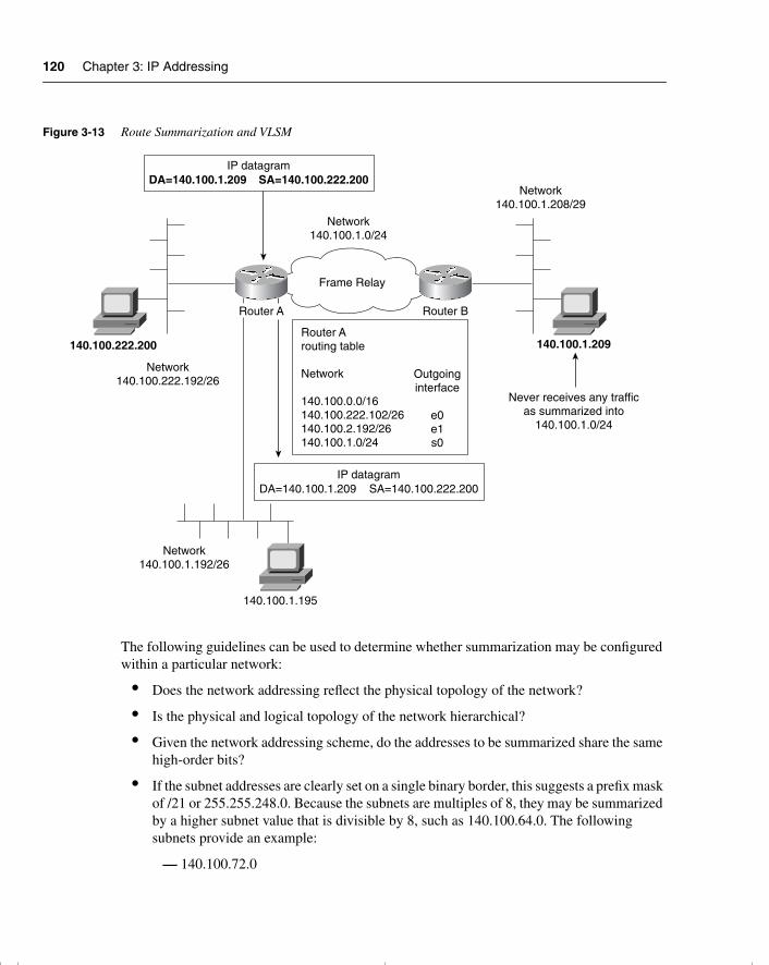
120 Chapter 3: IP Addressing
Figure 3-13 Route Summarization and VLSM
The following guidelines can be used to determine whether summarization may be configured within a particular network:
• Does the network addressing reflect the physical topology of the network?
• Is the physical and logical topology of the network hierarchical?
• Given the network addressing scheme, do the addresses to be summarized share the same high-order bits?
• If the subnet addresses are clearly set on a single binary border, this suggests a prefix mask of /21 or 255.255.248.0. Because the subnets are multiples of 8, they may be summarized by a higher subnet value that is divisible by 8, such as 140.100.64.0. The following subnets provide an example:
— 140.100.72.0
IP datagramDA=140.100.1.209 SA=140.100.222.200
IP datagramDA=140.100.1.209 SA=140.100.222.200
140.100.222.200
Network140.100.1.0/24
Network140.100.1.208/29
Frame Relay
Network140.100.222.192/26
Network140.100.1.192/26
Router A Router B
140.100.1.209
Never receives any trafficas summarized into
140.100.1.0/24
Router Arouting table
Network
140.100.0.0/16140.100.222.102/26140.100.2.192/26140.100.1.0/24
Outgoinginterface
e0e1s0
140.100.1.195
chpt_01.book Page 120 Thursday, December 21, 2000 6:22 PM
Designing IP Networks 121
— 140.100.80.0
— 140.100.88.0
— 140.100.96.0
— 140.100.104.0
— 140.100.112.0
• The nature of the traffic flow within the network should reflect the hierarchical logical and physical design.
• The routing protocol used must support VLSM.
Any design of a network requires very careful analysis of the current network and a clear understanding of the organization’s plans. Unfortunately, it is not always possible to determine the nature or flow of data through a network. Intranets and internal web pages have made the nature of the traffic within an organization far more unpredictable.
The increased tendency for organizations to need flexibility or mobility in addressing can make the IP design very challenging. The design would need to include Dynamic Host Configuration Protocol (DHCP) and Domain Name System (DNS) servers to maximize the flexibility of the network.
It is also important to fully understand the nature of the traffic in the network, particularly if it is a client/server environment (in which the design must allow for servers to communicate with each other and with their clients).
It may not be possible to use the existing addressing of the organization. If this is the case, the decision must be made to readdress the network. The decision may be made either because the network cannot scale because of the limitations of the NIC number that has been acquired from the Internet, or because the original design did not allow for the current environment or growth.
If the addressing scheme is inadequate in size, you have several options. The first is to apply to the Internet for another address or to use private addressing.
Private Addresses on the InternetPrivate addressing (along with VLSM, IP version 6 with an address field of 128 bits, and CIDR adressing and prefix routing) is one of the solutions the Internet community began to implement when it became apparent that there was a severe limitation to the number of IP addresses available on the Internet.
Private addressing was defined by RFC 1597 and was revised in RFC 1918. It was designed as an addressing method for an organization that has no intention of ever connecting to the Internet. If Internet connectivity were not required, there would be no requirement for a globally unique address from the Internet. The individual organization could address its network without any reference to the Internet, using one of the address ranges provided.
chpt_01.book Page 121 Thursday, December 21, 2000 6:22 PM
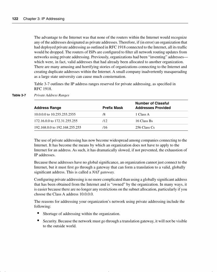
122 Chapter 3: IP Addressing
The advantage to the Internet was that none of the routers within the Internet would recognize any of the addresses designated as private addresses. Therefore, if (in error) an organization that had deployed private addressing as outlined in RFC 1918 connected to the Internet, all its traffic would be dropped. The routers of ISPs are configured to filter all network routing updates from networks using private addressing. Previously, organizations had been “inventing” addresses—which were, in fact, valid addresses that had already been allocated to another organization. There are many amusing and horrifying stories of organizations connecting to the Internet and creating duplicate addresses within the Internet. A small company inadvertently masquerading as a large state university can cause much consternation.
Table 3-7 outlines the IP address ranges reserved for private addressing, as specified in RFC 1918.
The use of private addressing has now become widespread among companies connecting to the Internet. It has become the means by which an organization does not have to apply to the Internet for an address. As such, it has dramatically slowed, if not prevented, the exhaustion of IP addresses.
Because these addresses have no global significance, an organization cannot just connect to the Internet, but it must first go through a gateway that can form a translation to a valid, globally significant address. This is called a NAT gateway.
Configuring private addressing is no more complicated than using a globally significant address that has been obtained from the Internet and is “owned” by the organization. In many ways, it is easier because there are no longer any restrictions on the subnet allocation, particularly if you choose the Class A address 10.0.0.0.
The reasons for addressing your organization’s network using private addressing include the following:
• Shortage of addressing within the organization.
• Security. Because the network must go through a translation gateway, it will not be visible to the outside world.
Table 3-7 Private Address Ranges
Address Range Prefix MaskNumber of Classful Addresses Provided
10.0.0.0 to 10.255.255.2555 /8 1 Class A
172.16.0.0 to 172.31.255.255 /12 16 Class Bs
192.168.0.0 to 192.168.255.255 /16 256 Class Cs
chpt_01.book Page 122 Thursday, December 21, 2000 6:22 PM
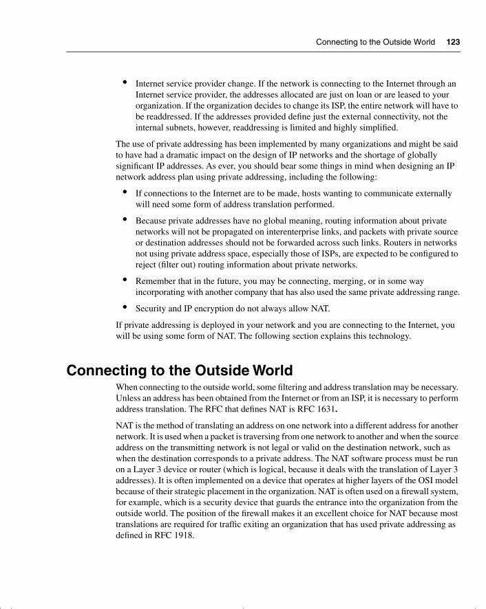
Connecting to the Outside World 123
• Internet service provider change. If the network is connecting to the Internet through an Internet service provider, the addresses allocated are just on loan or are leased to your organization. If the organization decides to change its ISP, the entire network will have to be readdressed. If the addresses provided define just the external connectivity, not the internal subnets, however, readdressing is limited and highly simplified.
The use of private addressing has been implemented by many organizations and might be said to have had a dramatic impact on the design of IP networks and the shortage of globally significant IP addresses. As ever, you should bear some things in mind when designing an IP network address plan using private addressing, including the following:
• If connections to the Internet are to be made, hosts wanting to communicate externally will need some form of address translation performed.
• Because private addresses have no global meaning, routing information about private networks will not be propagated on interenterprise links, and packets with private source or destination addresses should not be forwarded across such links. Routers in networks not using private address space, especially those of ISPs, are expected to be configured to reject (filter out) routing information about private networks.
• Remember that in the future, you may be connecting, merging, or in some way incorporating with another company that has also used the same private addressing range.
• Security and IP encryption do not always allow NAT.
If private addressing is deployed in your network and you are connecting to the Internet, you will be using some form of NAT. The following section explains this technology.
Connecting to the Outside WorldWhen connecting to the outside world, some filtering and address translation may be necessary. Unless an address has been obtained from the Internet or from an ISP, it is necessary to perform address translation. The RFC that defines NAT is RFC 1631.
NAT is the method of translating an address on one network into a different address for another network. It is used when a packet is traversing from one network to another and when the source address on the transmitting network is not legal or valid on the destination network, such as when the destination corresponds to a private address. The NAT software process must be run on a Layer 3 device or router (which is logical, because it deals with the translation of Layer 3 addresses). It is often implemented on a device that operates at higher layers of the OSI model because of their strategic placement in the organization. NAT is often used on a firewall system, for example, which is a security device that guards the entrance into the organization from the outside world. The position of the firewall makes it an excellent choice for NAT because most translations are required for traffic exiting an organization that has used private addressing as defined in RFC 1918.
chpt_01.book Page 123 Thursday, December 21, 2000 6:22 PM
124 Chapter 3: IP Addressing
NAT had a controversial childhood, particularly when it was used for translating addresses that did not use RFC 1918 guidelines for private addressing—perhaps the organization used an address that had just been imaginatively created by a network administrator. This practice occurred when there was no glimmer of a possibility that the organization would ever connect to the Internet. This certainty of never connecting is unrealistic, even for small companies, in an era when individual homes have connectivity to the Internet.
Therefore, NAT is useful in the following circumstances:
• To connect organizations that used address space issued to other organizations to the Internet
• To connect organizations that have used private address space defined in RFC 1918 and that want to connect to the Internet
• To connect together two organizations that have used the same private address, in line with RFC 1918
• When the organization wants to hide its addresses and is using NAT as part of firewall capabilities or is using additional security features
NOTE NAT is designed for use between an organization and the outside world, as shown in Figure 3-14. Although it may be used to solve addressing problems within an organization, this should be seen as a temporary fix. In such situations, NAT is seen as a transitory solution to keep the network functional while it is designed and readdressed appropriately.
Cisco supports the use of NAT on the majority of its platforms, as well as on its firewall product, the PIX box. Various levels of support are offered, depending on the platform and the IOS that has been purchased. NAT support is beginning to be bundled into the standard product offering. It started to be widely offered from IOS version 11.2 with the purchase of the “plus” software, and full NAT functionality became available in the Base IOS form version 12.0. NAT is currently at version 3.0. The following section lists the main features that Cisco offers.
TIP If you are considering implementing NAT instead of studying it for academic/exam purposes, contact Cisco via its web page. It is advisable to always contact the vendor of a product before purchase to fully appreciate the latest offerings and pricing. Because this industry is so dynamic, it is wise to verify the latest data.
chpt_01.book Page 124 Thursday, December 21, 2000 6:22 PM
Connecting to the Outside World 125
Figure 3-14 Connecting to the Outside World Using NAT
The Main Features of NATThe main features of NAT, as supported by Cisco, include the following:
• Static addressing—This one-to-one translation is manually configured.
• Dynamic source address translation—Here, a pool of addresses is defined. These addresses are used as the product of the translation. They must be a contiguous block of addresses.
• Port address translation (PAT)—Different local addresses (within the organization) are translated into one address that is globally significant for use on the Internet. The additional identifier of a TCP or UDP port unravels the multiple addresses that have been mapped to single addresses. The uniqueness of the different local addresses is ensured by the use of the port number mapped to the single address.
• Destination address rotary translation—This is used for traffic entering the organization from the outside. The destination address is matched against an access list, and the destination address is replaced by an address from the rotary pool. This is used only for TCP traffic, unless other translations are in effect.
NAT databaseInside source address
10.1.0.1210.1.0.55
Outside source address201.108.16.5201.108.16.6
201.108.16.5
10.1.0.12
"Outside network"the Internet
"Inside network"the organization
DA=131.110.18.9 | SA=201.108.16.5IP datagram
DA=131.110.18.9 | SA=10.1.0.12IP datagram
chpt_01.book Page 125 Thursday, December 21, 2000 6:22 PM
126 Chapter 3: IP Addressing
TIP Many other features are supported by Cisco. Therefore, if you intend to implement this technology, take a look at Cisco’s web page to discover the full range of options and features of the latest IOS version; Cisco is constantly upgrading and improving the feature set.
The basic operation of NAT is very straightforward, although the phraseology is rather confusing. The list of address definitions in Table 3-8 and the accompanying Figure 3-15 clarify the different terms.
To translate one network address into another, the process must differentiate between the functionality of the addresses being translated. Table 3-8 lists the categories of functions.
Figure 3-15 illustrates the terms of Table 3-8.
Table 3-8 Categories of Functions
Address Definition
Inside global The addresses that connect your organization indirectly to the Internet. Typically, these are the addresses provided by the ISP. These addresses are propagated outside the organization. They are globally unique and are the addresses used by the outside world to connect to inside the organization. Simply explained, they are the addresses that define how the inside addresses are seen globally by the outside.
Inside local The addresses that allow every end device in the organization to communicate. Although these addresses are unique within the organization, they are probably not globally unique. They may well be private addresses that conform to RFC 1918. They are the inside addresses as seen locally within the organization.
Outside global These are the Internet addresses (all the addresses outside the domain of the organization). They are the outside addresses as they appear to the global Internet.
Outside local These addresses are external to the organization. This is the destination address used by a host inside the organization connecting to the outside world. This will be the destination address of the packet propagated by the internal host. This is how the outside world is seen locally from inside the organization.
chpt_01.book Page 126 Thursday, December 21, 2000 6:22 PM
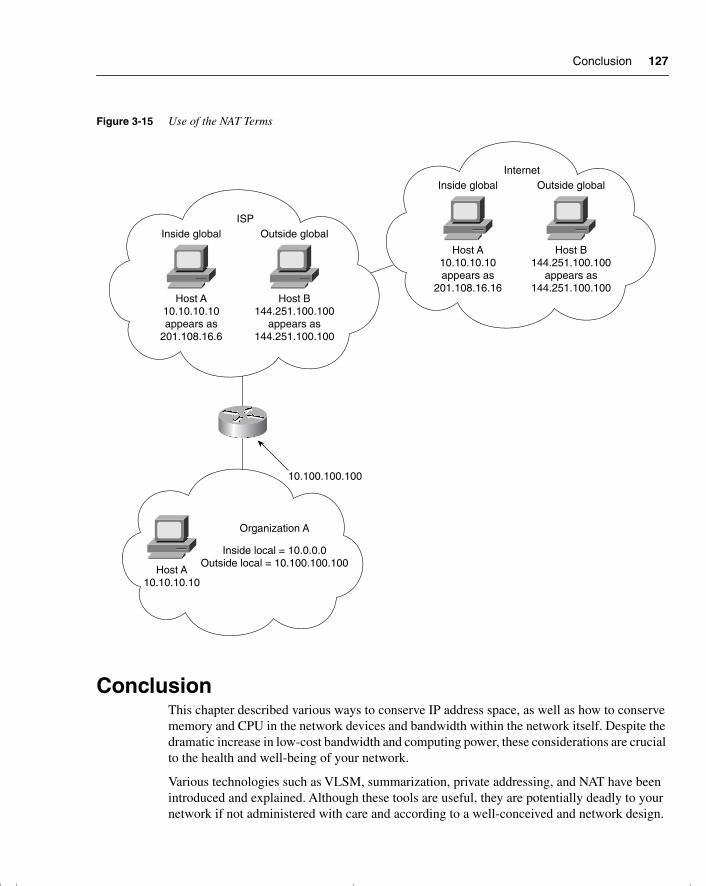
Conclusion 127
Figure 3-15 Use of the NAT Terms
ConclusionThis chapter described various ways to conserve IP address space, as well as how to conserve memory and CPU in the network devices and bandwidth within the network itself. Despite the dramatic increase in low-cost bandwidth and computing power, these considerations are crucial to the health and well-being of your network.
Various technologies such as VLSM, summarization, private addressing, and NAT have been introduced and explained. Although these tools are useful, they are potentially deadly to your network if not administered with care and according to a well-conceived and network design.
ISPInside global Outside global
Host A10.10.10.10appears as
201.108.16.6
Host A10.10.10.10
Host B144.251.100.100
appears as144.251.100.100
InternetInside global Outside global
Host A10.10.10.10appears as
201.108.16.16
Host B144.251.100.100
appears as144.251.100.100
10.100.100.100
Organization A
Inside local = 10.0.0.0Outside local = 10.100.100.100
chpt_01.book Page 127 Thursday, December 21, 2000 6:22 PM
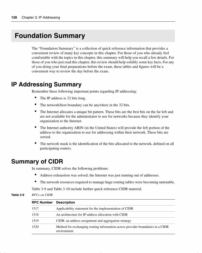
128 Chapter 3: IP Addressing
Foundation Summary
The “Foundation Summary” is a collection of quick reference information that provides a convenient review of many key concepts in this chapter. For those of you who already feel comfortable with the topics in this chapter, this summary will help you recall a few details. For those of you who just read this chapter, this review should help solidify some key facts. For any of you doing your final preparations before the exam, these tables and figures will be a convenient way to review the day before the exam.
IP Addressing SummaryRemember these following important points regarding IP addressing:
• The IP address is 32 bits long.
• The network/host boundary can be anywhere in the 32 bits.
• The Internet allocates a unique bit pattern. These bits are the first bits on the far left and are not available for the administrator to use for networks because they identify your organization to the Internet.
• The Internet authority ARIN (in the United States) will provide the left portion of the address to the organization to use for addressing within their network. These bits are zeroed.
• The network mask is the identification of the bits allocated to the network, defined on all participating routers.
Summary of CIDRIn summary, CIDR solves the following problems:
• Address exhaustion was solved; the Internet was just running out of addresses.
• The network resources required to manage huge routing tables were becoming untenable.
Table 3-9 and Table 3-10 include further quick reference CIDR material.
Table 3-9 RFCs on CIDR
RFC Number Description
1517 Applicability statement for the implementation of CIDR
1518 An architecture for IP address allocation with CIDR
1519 CIDR: an address assignment and aggregation strategy
1520 Method for exchanging routing information across provider boundaries in a CIDR environment
chpt_01.book Page 128 Thursday, December 21, 2000 6:22 PM
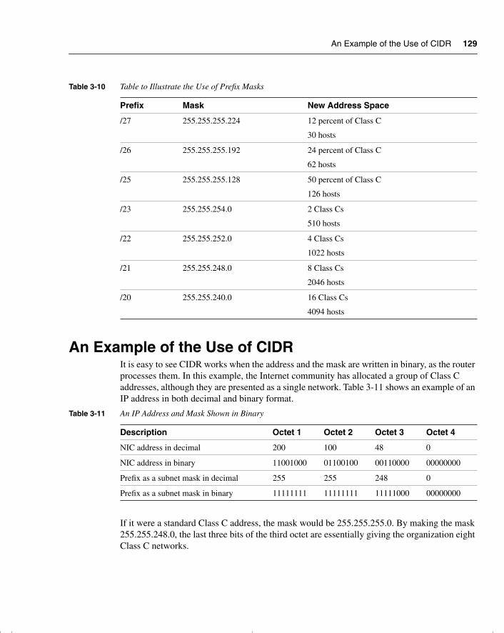
An Example of the Use of CIDR 129
An Example of the Use of CIDRIt is easy to see CIDR works when the address and the mask are written in binary, as the router processes them. In this example, the Internet community has allocated a group of Class C addresses, although they are presented as a single network. Table 3-11 shows an example of an IP address in both decimal and binary format.
If it were a standard Class C address, the mask would be 255.255.255.0. By making the mask 255.255.248.0, the last three bits of the third octet are essentially giving the organization eight Class C networks.
Table 3-10 Table to Illustrate the Use of Prefix Masks
Prefix Mask New Address Space
/27 255.255.255.224 12 percent of Class C
30 hosts
/26 255.255.255.192 24 percent of Class C
62 hosts
/25 255.255.255.128 50 percent of Class C
126 hosts
/23 255.255.254.0 2 Class Cs
510 hosts
/22 255.255.252.0 4 Class Cs
1022 hosts
/21 255.255.248.0 8 Class Cs
2046 hosts
/20 255.255.240.0 16 Class Cs
4094 hosts
Table 3-11 An IP Address and Mask Shown in Binary
Description Octet 1 Octet 2 Octet 3 Octet 4
NIC address in decimal 200 100 48 0
NIC address in binary 11001000 01100100 00110000 00000000
Prefix as a subnet mask in decimal 255 255 248 0
Prefix as a subnet mask in binary 11111111 11111111 11111000 00000000
chpt_01.book Page 129 Thursday, December 21, 2000 6:22 PM
130 Chapter 3: IP Addressing
Rules for VLSMThe rules for variably subnetting an IP address, are remarkably straightforward. The key is to remember that a hierarchical design in the addressing scheme is the goal. The physical network design also must reflect this logical hierarchy (as discussed in Chapter 2). After the physical design is mapped, the logical structure can be placed on top of it.
The following main rules apply when subnetting:
• A subnet can be used to address hosts, or it can be used for further subnetting.
• Within the allocation of subsequent subnets, the rule of not using all zeros or ones does not apply.
• The routing protocol must carry the subnet mask in its updates.
• Multiple IP addresses intended to be summarized must have the same high-order bits.
• Routing decisions are made on the entire address, preferring the longest bit pattern available.
The two main reasons for using VLSM are as follows:
• To make efficient use of the available addressing
• To enforce a good hierarchical design, allowing summarization and documentation
Advantages of Summarization The advantages of summarization are as follows:
• To reduce the size of the routing table
• To reduce network overhead
• To make communication of routing updates more efficient
• To reduce CPU and memory utilization
• To simplify management
• To maximize the use of IP addresses
• To isolate topographical changes from other areas
Table 3-12 outlines the IP address ranges reserved for private addressing, as specified in RFC 1918.
chpt_01.book Page 130 Thursday, December 21, 2000 6:22 PM
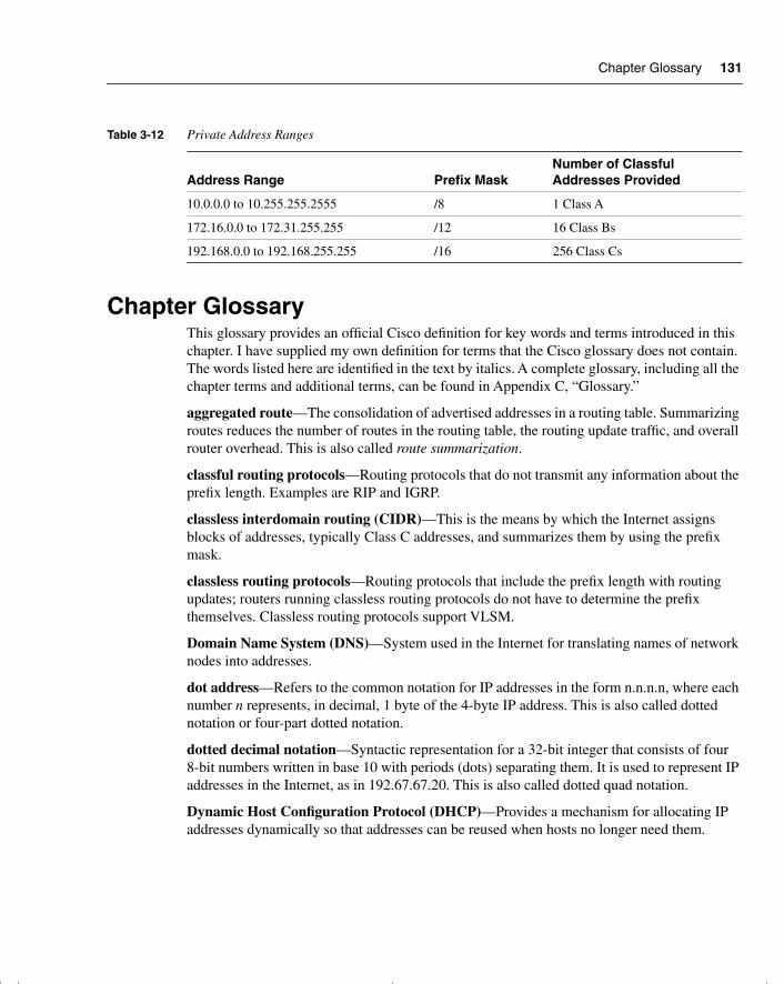
Chapter Glossary 131
Chapter GlossaryThis glossary provides an official Cisco definition for key words and terms introduced in this chapter. I have supplied my own definition for terms that the Cisco glossary does not contain. The words listed here are identified in the text by italics. A complete glossary, including all the chapter terms and additional terms, can be found in Appendix C, “Glossary.”
aggregated route—The consolidation of advertised addresses in a routing table. Summarizing routes reduces the number of routes in the routing table, the routing update traffic, and overall router overhead. This is also called route summarization.
classful routing protocols—Routing protocols that do not transmit any information about the prefix length. Examples are RIP and IGRP.
classless interdomain routing (CIDR)—This is the means by which the Internet assigns blocks of addresses, typically Class C addresses, and summarizes them by using the prefix mask.
classless routing protocols—Routing protocols that include the prefix length with routing updates; routers running classless routing protocols do not have to determine the prefix themselves. Classless routing protocols support VLSM.
Domain Name System (DNS)—System used in the Internet for translating names of network nodes into addresses.
dot address—Refers to the common notation for IP addresses in the form n.n.n.n, where each number n represents, in decimal, 1 byte of the 4-byte IP address. This is also called dotted notation or four-part dotted notation.
dotted decimal notation—Syntactic representation for a 32-bit integer that consists of four 8-bit numbers written in base 10 with periods (dots) separating them. It is used to represent IP addresses in the Internet, as in 192.67.67.20. This is also called dotted quad notation.
Dynamic Host Configuration Protocol (DHCP)—Provides a mechanism for allocating IP addresses dynamically so that addresses can be reused when hosts no longer need them.
Table 3-12 Private Address Ranges
Address Range Prefix MaskNumber of Classful Addresses Provided
10.0.0.0 to 10.255.255.2555 /8 1 Class A
172.16.0.0 to 172.31.255.255 /12 16 Class Bs
192.168.0.0 to 192.168.255.255 /16 256 Class Cs
chpt_01.book Page 131 Thursday, December 21, 2000 6:22 PM
132 Chapter 3: IP Addressing
first octet rule—The mechanism by which the Layer 3 device identifies the class of IP address. If the protocol is a classful address, it is the only means available to determine the network portion of an address to which it is not directly connected.
flooding—A traffic-passing technique used by switches and bridges in which traffic received on an interface is sent out all the interfaces of that device, except the interface on which the information was originally received.
internet—Short for internetwork. Not to be confused with the Internet. See also internetwork.
Internet Assigned Numbers Authority (IANA)—Responsible for address allocation in the Internet.
internetwork—A collection of networks interconnected by routers and other devices that functions (generally) as a single network. It is sometimes called an internet, which is not to be confused with the Internet.
Layer 3 switching—Used in the context of VLANs, the mechanism by which a switch will route between VLANs. It also refers to routers, when the routing decision has been made and the result has been cached. The subsequent lookup involves switching (for example, fast switching), but on a Layer 3 decision.
logical AND—The mechanism by which a subnet is derived from an IP host address. The router maps the subnet mask, in binary, onto the host address, in binary. The result of the logical AND is the subnet address.
Network Address Translation (NAT)—Mechanism for reducing the need for globally unique IP addresses. NAT allows an organization with addresses that are not globally unique to connect to the Internet by translating those addresses into globally routable address space. Also known as Network Address Translator.
prefix mask—The prefix mask identifies the number of bits in the subnet mask. It is written in the /xx format after the address. It is used in supernetting and router aggregation.
private addressing—Private addressing is the means by which an organization can address its network without using a registered address from the Internet. This saves considerable address space in the Internet and eases restrictions within the organization.
routing table—A table stored in a router or some other internetworking device that keeps track of routes to particular network destinations and metrics associated with those routes.
subnet mask—A 32-bit number that is associated with an IP address; each bit in the subnet mask indicates how to interpret the corresponding bit in the IP address. In binary, a subnet mask bit of 1 indicates that the corresponding bit in the IP address is a network or subnet bit; a subnet mask bit of 0 indicates that the corresponding bit in the IP address is a host bit. The subnet mask then indicates how many bits have been borrowed from the host field for the subnet field. It sometimes is referred to simply as mask.
chpt_01.book Page 132 Thursday, December 21, 2000 6:22 PM

Chapter Glossary 133
supernet—A summarization of class addresses given out by the Internet community. For example a group of Class C addresses 200.100.16.0 through 200.100.31.0 could be summarized into the address 200.100.16.0 with a mask of 255.255.224.0 (/19).
variable-length subnet mask (VLSM)—The capability to specify a different subnet mask for the same network number on different subnets. VLSM can help optimize available address space. Some protocols do not allow the use of VLSM. See also classless routing protocols.
virtual LAN—A logical grouping of devices, identified on switch ports instead of a physical segment attached to a router. This means that the devices associated with the logical network do not have to be geographically local to one another.
chpt_01.book Page 133 Thursday, December 21, 2000 6:22 PM
134 Chapter 3: IP Addressing
Q&A
The following questions test your understanding of the topics covered in this chapter. The final questions in this section repeat the opening “Do I Know This Already?” questions. These are repeated to enable you to test your progress. After you have answered the questions, find the answers in Appendix A. If you get an answer wrong, review the answer and ensure that you understand the reason for your mistake. If you are confused by the answer, refer to the appropriate text in the chapter to review the concepts.
1 Identify one criterion to help determine a subnet mask for classful addressing when designing a network-addressing scheme.
______________________________________________________________________
______________________________________________________________________
______________________________________________________________________
2 Which command is used to forward broadcast traffic across a router to a particular destination?
______________________________________________________________________
______________________________________________________________________
______________________________________________________________________
3 With a classless address of 204.1.64.0/20, what is the range of classful addresses that are included in the address? Write your answer in dotted decimal and the third octet in binary notation.
______________________________________________________________________
______________________________________________________________________
______________________________________________________________________
4 What is a discontiguous network?
______________________________________________________________________
______________________________________________________________________
______________________________________________________________________
chpt_01.book Page 134 Thursday, December 21, 2000 6:22 PM
Q&A 135
5 For VLSM to be available as a design option in the network, what characteristic must the routing protocol possess?
_______________________________________________________________________
_______________________________________________________________________
_______________________________________________________________________
6 If summarization is to be implemented in the network, name one design criterion for the addressing scheme that must be in place?
_______________________________________________________________________
_______________________________________________________________________
_______________________________________________________________________
7 What networks are provided in RFC 1918, and what prefix mask accompanies each network?
_______________________________________________________________________
_______________________________________________________________________
_______________________________________________________________________
8 If the host portion of a subnet has been used to identify end devices, can that subnet be used again for VLSM?
_______________________________________________________________________
_______________________________________________________________________
_______________________________________________________________________
9 Describe the purpose of the ip forward-protocol command.
_______________________________________________________________________
_______________________________________________________________________
_______________________________________________________________________
10 Which command is used on point-to-point lines to conserve IP address space?
_______________________________________________________________________
_______________________________________________________________________
_______________________________________________________________________
chpt_01.book Page 135 Thursday, December 21, 2000 6:22 PM
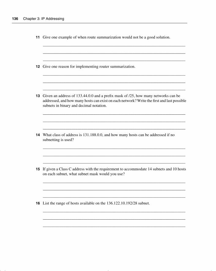
136 Chapter 3: IP Addressing
11 Give one example of when route summarization would not be a good solution.
______________________________________________________________________
______________________________________________________________________
______________________________________________________________________
12 Give one reason for implementing router summarization.
______________________________________________________________________
______________________________________________________________________
______________________________________________________________________
13 Given an address of 133.44.0.0 and a prefix mask of /25, how many networks can be addressed, and how many hosts can exist on each network? Write the first and last possible subnets in binary and decimal notation.
______________________________________________________________________
______________________________________________________________________
______________________________________________________________________
14 What class of address is 131.188.0.0, and how many hosts can be addressed if no subnetting is used?
______________________________________________________________________
______________________________________________________________________
______________________________________________________________________
15 If given a Class C address with the requirement to accommodate 14 subnets and 10 hosts on each subnet, what subnet mask would you use?
______________________________________________________________________
______________________________________________________________________
______________________________________________________________________
16 List the range of hosts available on the 136.122.10.192/28 subnet.
______________________________________________________________________
______________________________________________________________________
______________________________________________________________________
chpt_01.book Page 136 Thursday, December 21, 2000 6:22 PM

Q&A 137
17 Convert the subnet address 56.98.5.0/24 to binary notation, and state the class to which it belongs.
_______________________________________________________________________
_______________________________________________________________________
_______________________________________________________________________
18 Write out the decimal notation of the following subnet mask presented in the binary notation of 11111111.11111111.11111111.11111000.
_______________________________________________________________________
_______________________________________________________________________
_______________________________________________________________________
19 What does VLSM stand for?
_______________________________________________________________________
_______________________________________________________________________
_______________________________________________________________________
20 The Class B network address of 133.222.0.0 has been given a mask of 255.255.255.0. The subnets 133.222.8.0, 133.222.9.0, 133.222.10.0, 133.222.11.0, 133.222.12.0, 133.222.13.0, and 133.222.14.0 need to be summarized using VLSM. Give the subnet and new mask to achieve this summarization.
_______________________________________________________________________
_______________________________________________________________________
_______________________________________________________________________
21 Is 201.111.16.0/20 a valid subnet mask?
_______________________________________________________________________
_______________________________________________________________________
_______________________________________________________________________
22 Which routing protocols support VLSM?
_______________________________________________________________________
_______________________________________________________________________
_______________________________________________________________________
chpt_01.book Page 137 Thursday, December 21, 2000 6:22 PM
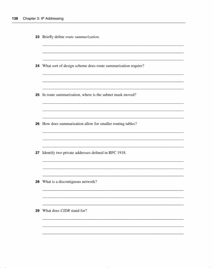
138 Chapter 3: IP Addressing
23 Briefly define route summarization.
______________________________________________________________________
______________________________________________________________________
______________________________________________________________________
24 What sort of design scheme does route summarization require?
______________________________________________________________________
______________________________________________________________________
______________________________________________________________________
25 In route summarization, where is the subnet mask moved?
______________________________________________________________________
______________________________________________________________________
______________________________________________________________________
26 How does summarization allow for smaller routing tables?
______________________________________________________________________
______________________________________________________________________
______________________________________________________________________
27 Identify two private addresses defined in RFC 1918.
______________________________________________________________________
______________________________________________________________________
______________________________________________________________________
28 What is a discontiguous network?
______________________________________________________________________
______________________________________________________________________
______________________________________________________________________
29 What does CIDR stand for?
______________________________________________________________________
______________________________________________________________________
______________________________________________________________________
chpt_01.book Page 138 Thursday, December 21, 2000 6:22 PM

Q&A 139
30 Which RFC is responsible for first describing the use of subnet masking?
_______________________________________________________________________
_______________________________________________________________________
_______________________________________________________________________
chpt_01.book Page 139 Thursday, December 21, 2000 6:22 PM
140 Chapter 3: IP Addressing
Scenarios
The following scenarios and questions are designed to draw together the content of the chapter and exercise your understanding of the concepts. There is not necessarily a right answer. The thought process and practice in manipulating the concepts is the goal of this section. The answers to the scenario questions are found at the end of this chapter.
Scenario 3-1This scenario concentrates on correcting an addressing scheme in our original case study of Mental Merge. A network administrator devised the addressing scheme before there was any intention of connecting the company to the Internet and before the company had regional offices. Addresses were subsequently allocated without any policy or administrative control. This has led to problems in the current organization, which now needs to summarize its addresses. Using the addressing scheme in Figure 3-16, answer the following questions.
1 There are serious problems with the addressing scheme in Figure 3-16. If the network had this addressing scheme, would summarization be possible?
2 Design an alternative addressing scheme using VLSM that would summarize to the regional level.
3 Write out the addressing scheme in both binary and dotted decimal notation.
4 Could these addressing requirements be achieved with a Class C address?
5 If the answer to the preceding question is yes, write out the dotted decimal and binary notation to support it. If the answer is no, how many Class C addresses would be required? (Again, write out the dotted decimal and binary notation to support your argument.)
chpt_01.book Page 140 Thursday, December 21, 2000 6:22 PM
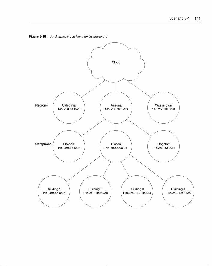
Scenario 3-1 141
Figure 3-16 An Addressing Scheme for Scenario 3-1
Cloud
California145.250.64.0/20
Regions
Campuses
Arizona145.250.32.0/20
Washington145.250.96.0/20
Phoenix145.250.97.0/24
Building 1145.250.65.0/28
Building 2145.250.192.0/28
Building 3145.250.192.192/28
Building 4145.250.128.0/28
Tucson145.250.65.0/24
Flagstaff145.250.33.0/24
chpt_01.book Page 141 Thursday, December 21, 2000 6:22 PM
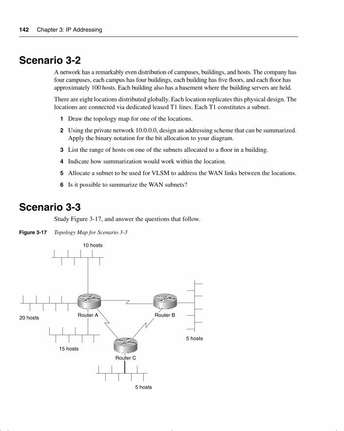
142 Chapter 3: IP Addressing
Scenario 3-2A network has a remarkably even distribution of campuses, buildings, and hosts. The company has four campuses, each campus has four buildings, each building has five floors, and each floor has approximately 100 hosts. Each building also has a basement where the building servers are held.
There are eight locations distributed globally. Each location replicates this physical design. The locations are connected via dedicated leased T1 lines. Each T1 constitutes a subnet.
1 Draw the topology map for one of the locations.
2 Using the private network 10.0.0.0, design an addressing scheme that can be summarized. Apply the binary notation for the bit allocation to your diagram.
3 List the range of hosts on one of the subnets allocated to a floor in a building.
4 Indicate how summarization would work within the location.
5 Allocate a subnet to be used for VLSM to address the WAN links between the locations.
6 Is it possible to summarize the WAN subnets?
Scenario 3-3Study Figure 3-17, and answer the questions that follow.
Figure 3-17 Topology Map for Scenario 3-3
20 hosts
10 hosts
15 hosts
5 hosts
5 hosts
Router A Router B
Router C
chpt_01.book Page 142 Thursday, December 21, 2000 6:22 PM

Scenario 3-3 143
1 To address this network, what class of address would you apply to the Internet?
2 Could you use VLSM? Give reasons for your answer.
3 If you could use VLSM, write out the masks that you would deploy in binary notation.
4 Could summarization be implemented?
chpt_01.book Page 143 Thursday, December 21, 2000 6:22 PM
144 Chapter 3: IP Addressing
Scenario Answers
The answers are in bold. The answers provided in this section are not necessarily the only possible answers to the questions. The questions are designed to test your knowledge and to give practical exercise in certain key areas. This section is intended to test and exercise skills and concepts detailed in the body of this chapter.
If your answer is different, ask yourself whether it follows the tenets explained in the answers provided. Your answer is correct not if it matches the solution provided in the book, but rather if it has included the principles of design laid out in the chapter.
In this way, the testing provided in these scenarios is deeper: It examines not only your knowledge, but also your understanding and capability to apply that knowledge to problems.
If you do not get the correct answer, refer back to the text and review the subject tested. Be certain to also review your notes on the question to ensure that you understand the principles of the subject.
Scenario 3-1 Answers1 There are serious problems with the addressing scheme in Figure 3-16. If the network had
this addressing scheme, would summarization be possible?
Summarization is not possible, for the following reasons:
— The buildings do not share the same high-order bits as the campus.
— The campuses do not share the same high-order bits as the region.
— Depending on the physical design, the California campus and Building 1 could be seen as duplicate addresses.
2 Design an alternative addressing scheme using VLSM that would summarize to the regional level.
See Table 3-13.
3 Write out the addressing scheme in both binary and dotted decimal notation.
See Table 3-13.
Table 3-13 shows an alternative solution using the same address as before and the same bit allocation. If you have changed the bit allocation, ensure that there are enough bits for each level of the network. The requirements have not been stated, so you will have to state them for yourself or use the limited information that is provided. The question identifies three states, and you can assume three campuses in each state. Each campus has four buildings.
chpt_01.book Page 144 Thursday, December 21, 2000 6:22 PM
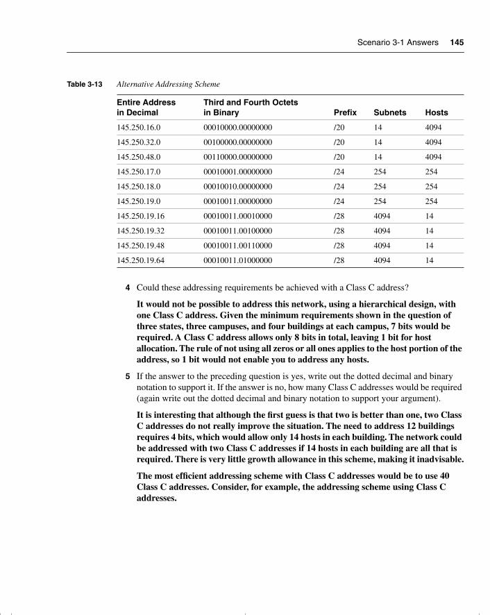
Scenario 3-1 Answers 145
4 Could these addressing requirements be achieved with a Class C address?
It would not be possible to address this network, using a hierarchical design, with one Class C address. Given the minimum requirements shown in the question of three states, three campuses, and four buildings at each campus, 7 bits would be required. A Class C address allows only 8 bits in total, leaving 1 bit for host allocation. The rule of not using all zeros or all ones applies to the host portion of the address, so 1 bit would not enable you to address any hosts.
5 If the answer to the preceding question is yes, write out the dotted decimal and binary notation to support it. If the answer is no, how many Class C addresses would be required (again write out the dotted decimal and binary notation to support your argument).
It is interesting that although the first guess is that two is better than one, two Class C addresses do not really improve the situation. The need to address 12 buildings requires 4 bits, which would allow only 14 hosts in each building. The network could be addressed with two Class C addresses if 14 hosts in each building are all that is required. There is very little growth allowance in this scheme, making it inadvisable.
The most efficient addressing scheme with Class C addresses would be to use 40 Class C addresses. Consider, for example, the addressing scheme using Class C addresses.
Table 3-13 Alternative Addressing Scheme
Entire Address in Decimal
Third and Fourth Octets in Binary Prefix Subnets Hosts
145.250.16.0 00010000.00000000 /20 14 4094
145.250.32.0 00100000.00000000 /20 14 4094
145.250.48.0 00110000.00000000 /20 14 4094
145.250.17.0 00010001.00000000 /24 254 254
145.250.18.0 00010010.00000000 /24 254 254
145.250.19.0 00010011.00000000 /24 254 254
145.250.19.16 00010011.00010000 /28 4094 14
145.250.19.32 00010011.00100000 /28 4094 14
145.250.19.48 00010011.00110000 /28 4094 14
145.250.19.64 00010011.01000000 /28 4094 14
chpt_01.book Page 145 Thursday, December 21, 2000 6:22 PM
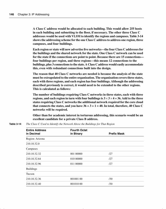
146 Chapter 3: IP Addressing
A Class C address would be allocated to each building. This would allow 255 hosts in each building and subnetting to the floor, if necessary. The other three Class C addresses would be used with VLSM to identify the regions and campuses. Table 3-14 shows the addressing scheme for the one Class C address to address one region, three campuses, and four buildings.
Each region or state will now advertise five networks—the four Class C addresses for the buildings and the shared network for the state. One Class C network can be used for the state if the connections are point to point. Because there are 15 connections—four buildings per region, and three regions—this means 12 connections to the buildings, plus 3 connections to the state. A Class C address would easily accommodate this, even with redundant connections built into the design.
The reason that 40 Class C networks are needed is because the analysis of the state must be extrapolated to the entire organization. The organization covers three states, each with three regions, and each region has four buildings. Although the addressing described previously is correct, it would need to be extended to the other regions. This is calculated as follows:
The number of buildings requiring Class C networks in three states, each with three regions, and each region in turn with four buildings is 3 × 3 × 4 = 36. Add to the three states requiring Class C networks the additional network required for the core cloud that connects the states, and you have 36 + 3 + 1 = 40. In total, therefore, 40 Class C networks will be required.
Other than for academic interest in torturous addressing, this scenario would be an excellent candidate for a private Class B address.
Table 3-14 The Class C Used to Identify the Network Above the Buildings for That Region
Entire Address in Decimal
Fourth Octet in Binary Prefix Mask
Region: Arizona
210.10.32.0
Campuses
210.10.32.32 001 00000 /27
210.10.32.64 010 00000 /27
210.10.32.96 011 00000 /27
Buildings
Tucson
210.10.32.36 001001 00 /30
210.10.32.40 001010 00 /30
chpt_01.book Page 146 Thursday, December 21, 2000 6:22 PM
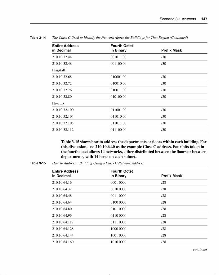
Scenario 3-1 Answers 147
Table 3-15 shows how to address the departments or floors within each building. For this discussion, use 210.10.64.0 as the example Class C address. Four bits taken in the fourth octet allows 14 networks, either distributed between the floors or between departments, with 14 hosts on each subnet.
210.10.32.44 001011 00 /30
210.10.32.48 001100 00 /30
Flagstaff
210.10.32.68 010001 00 /30
210.10.32.72 010010 00 /30
210.10.32.76 010011 00 /30
210.10.32.80 010100 00 /30
Phoenix
210.10.32.100 011001 00 /30
210.10.32.104 011010 00 /30
210.10.32.108 011011 00 /30
210.10.32.112 011100 00 /30
Table 3-15 How to Address a Building Using a Class C Network Address
Entire Address in Decimal
Fourth Octet in Binary Prefix Mask
210.10.64.16 0001 0000 /28
210.10.64.32 0010 0000 /28
210.10.64.48 0011 0000 /28
210.10.64.64 0100 0000 /28
210.10.64.80 0101 0000 /28
210.10.64.96 0110 0000 /28
210.10.64.112 0111 0000 /28
210.10.64.128 1000 0000 /28
210.10.64.144 1001 0000 /28
210.10.64.160 1010 0000 /28
continues
Table 3-14 The Class C Used to Identify the Network Above the Buildings for That Region (Continued)
Entire Address in Decimal
Fourth Octet in Binary Prefix Mask
chpt_01.book Page 147 Thursday, December 21, 2000 6:22 PM
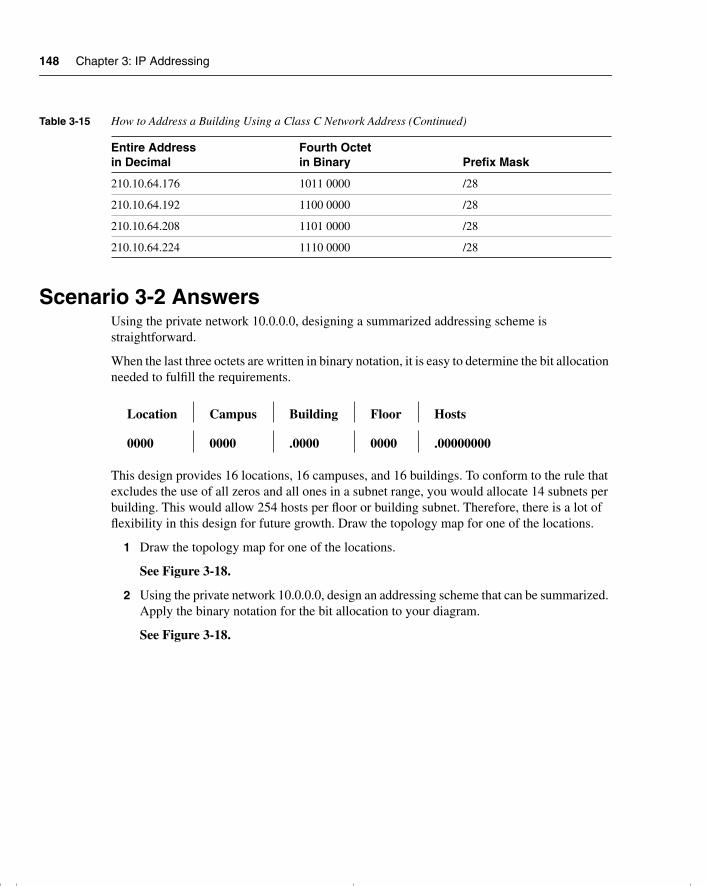
148 Chapter 3: IP Addressing
Scenario 3-2 AnswersUsing the private network 10.0.0.0, designing a summarized addressing scheme is straightforward.
When the last three octets are written in binary notation, it is easy to determine the bit allocation needed to fulfill the requirements.
This design provides 16 locations, 16 campuses, and 16 buildings. To conform to the rule that excludes the use of all zeros and all ones in a subnet range, you would allocate 14 subnets per building. This would allow 254 hosts per floor or building subnet. Therefore, there is a lot of flexibility in this design for future growth. Draw the topology map for one of the locations.
1 Draw the topology map for one of the locations.
See Figure 3-18.
2 Using the private network 10.0.0.0, design an addressing scheme that can be summarized. Apply the binary notation for the bit allocation to your diagram.
See Figure 3-18.
210.10.64.176 1011 0000 /28
210.10.64.192 1100 0000 /28
210.10.64.208 1101 0000 /28
210.10.64.224 1110 0000 /28
Location Campus Building Floor Hosts
0000 0000 .0000 0000 .00000000
Table 3-15 How to Address a Building Using a Class C Network Address (Continued)
Entire Address in Decimal
Fourth Octet in Binary Prefix Mask
chpt_01.book Page 148 Thursday, December 21, 2000 6:22 PM
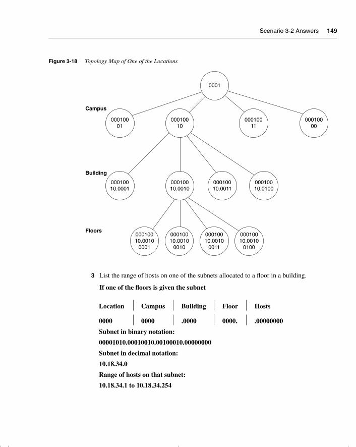
Scenario 3-2 Answers 149
Figure 3-18 Topology Map of One of the Locations
3 List the range of hosts on one of the subnets allocated to a floor in a building.
If one of the floors is given the subnet
Location Campus Building Floor Hosts
0000 0000 .0000 0000. .00000000
Subnet in binary notation:
00001010.00010010.00100010.00000000
Subnet in decimal notation:
10.18.34.0
Range of hosts on that subnet:
10.18.34.1 to 10.18.34.254
Campus
Building
Floors
0001
00010001
00010010
00010010.0001
00010010.0010
00010010.0010
0001
00010010.0010
0010
00010010.0010
0011
00010010.0010
0100
00010010.0011
00010010.0100
00010011
00010000
chpt_01.book Page 149 Thursday, December 21, 2000 6:22 PM
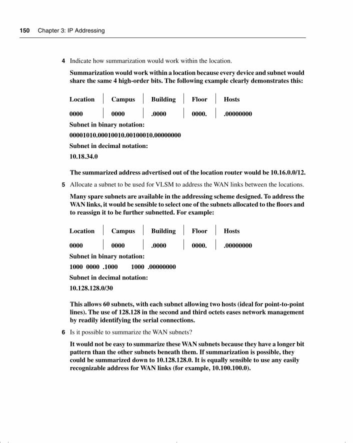
150 Chapter 3: IP Addressing
4 Indicate how summarization would work within the location.
Summarization would work within a location because every device and subnet would share the same 4 high-order bits. The following example clearly demonstrates this:
The summarized address advertised out of the location router would be 10.16.0.0/12.
5 Allocate a subnet to be used for VLSM to address the WAN links between the locations.
Many spare subnets are available in the addressing scheme designed. To address the WAN links, it would be sensible to select one of the subnets allocated to the floors and to reassign it to be further subnetted. For example:
This allows 60 subnets, with each subnet allowing two hosts (ideal for point-to-point lines). The use of 128.128 in the second and third octets eases network management by readily identifying the serial connections.
6 Is it possible to summarize the WAN subnets?
It would not be easy to summarize these WAN subnets because they have a longer bit pattern than the other subnets beneath them. If summarization is possible, they could be summarized down to 10.128.128.0. It is equally sensible to use any easily recognizable address for WAN links (for example, 10.100.100.0).
Location Campus Building Floor Hosts
0000 0000 .0000 0000. .00000000
Subnet in binary notation:
00001010.00010010.00100010.00000000
Subnet in decimal notation:
10.18.34.0
Location Campus Building Floor Hosts
0000 0000 .0000 0000. .00000000
Subnet in binary notation:
1000 0000 .1000 1000 .00000000
Subnet in decimal notation:
10.128.128.0/30
chpt_01.book Page 150 Thursday, December 21, 2000 6:22 PM
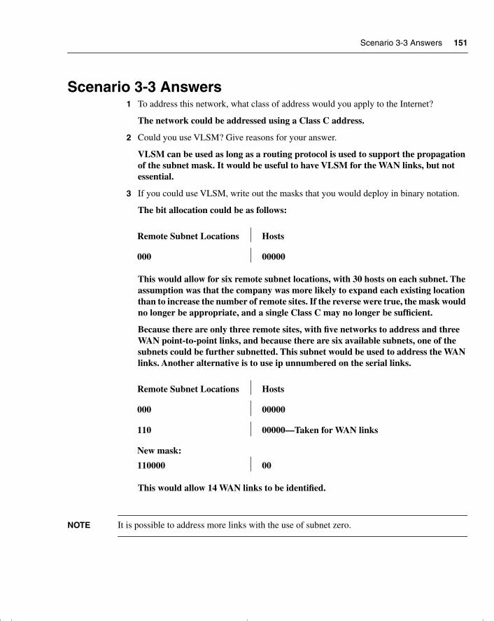
Scenario 3-3 Answers 151
Scenario 3-3 Answers1 To address this network, what class of address would you apply to the Internet?
The network could be addressed using a Class C address.
2 Could you use VLSM? Give reasons for your answer.
VLSM can be used as long as a routing protocol is used to support the propagation of the subnet mask. It would be useful to have VLSM for the WAN links, but not essential.
3 If you could use VLSM, write out the masks that you would deploy in binary notation.
The bit allocation could be as follows:
This would allow for six remote subnet locations, with 30 hosts on each subnet. The assumption was that the company was more likely to expand each existing location than to increase the number of remote sites. If the reverse were true, the mask would no longer be appropriate, and a single Class C may no longer be sufficient.
Because there are only three remote sites, with five networks to address and three WAN point-to-point links, and because there are six available subnets, one of the subnets could be further subnetted. This subnet would be used to address the WAN links. Another alternative is to use ip unnumbered on the serial links.
This would allow 14 WAN links to be identified.
NOTE It is possible to address more links with the use of subnet zero.
Remote Subnet Locations Hosts
000 00000
Remote Subnet Locations Hosts
000 00000
110 00000—Taken for WAN links
New mask:
110000 00
chpt_01.book Page 151 Thursday, December 21, 2000 6:22 PM
152 Chapter 3: IP Addressing
4 Could summarization be implemented?
In this size of a network, summarization is not a concern and would not be possible; also, there is no hierarchy in the physical design.
It should be noted that this design does not allow for much network growth, and the organization may want to consider using a private Class B network.
chpt_01.book Page 152 Thursday, December 21, 2000 6:22 PM

chpt_01.book Page 153 Thursday, December 21, 2000 6:22 PM
This chapter covers the following topics that you will need to master to pass the CCNP/CCDP Routing exam:
• Explaining the routing process.
• Determining the requirements of the routing process.
• Analyzing the routing table.
• Describing the differences between a classful and classless routing protocol.
• Comparing the difference between a distance vector and link-state routing protocol, including an explanation of how routing tables are maintained, path selection, administrative distance, metrics, and convergence.
• Reviewing Cisco features that include show ip route and clear ip route.
chpt_01.book Page 154 Thursday, December 21, 2000 6:22 PM
C H A P T E R 4
IP Routing Principles
The topics in this chapter are the basis of the BSCN course that feeds the Routing exam. The very name of the exam—the Routing exam—suggests that there are more than likely some questions on this very topic. In this chapter, the concepts of routing with IP and the mechanics of the process are dealt with generically as a foundation for the subsequent chapters, which deal with the individual routing protocols. The topics will directly reflect questions on the Routing exam. If you do not understand the contents of this chapter, it will be impossible for you to pass the exam. Some of this chapter reviews subjects dealt with in the ICND course. The subsequent chapters assume the comprehension of the subjects covered in this chapter.
How to Best Use This ChapterBy taking the following steps, you can make better use of your study time:
• Keep your notes and the answers for all your work with this book in one place, for easy reference.
• When you take a quiz, write down your answers. Studies show that retention significantly increases by writing down facts and concepts, even if you never look at the information again.
• Use the diagram in Figure 4-1 to guide you to the next step.
chpt_01.book Page 155 Thursday, December 21, 2000 6:22 PM
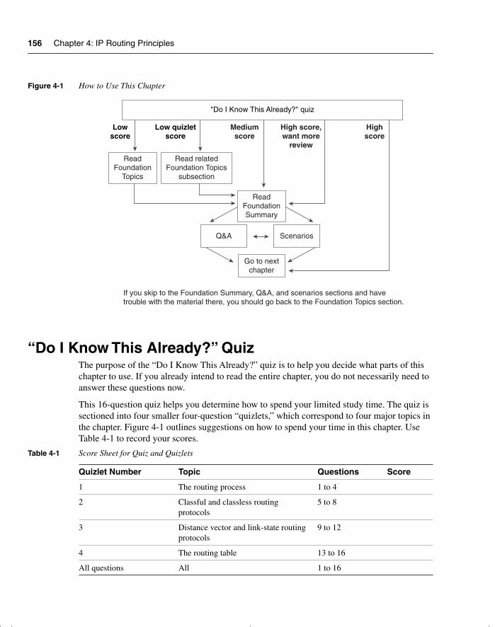
156 Chapter 4: IP Routing Principles
Figure 4-1 How to Use This Chapter
“Do I Know This Already?” QuizThe purpose of the “Do I Know This Already?” quiz is to help you decide what parts of this chapter to use. If you already intend to read the entire chapter, you do not necessarily need to answer these questions now.
This 16-question quiz helps you determine how to spend your limited study time. The quiz is sectioned into four smaller four-question “quizlets,” which correspond to four major topics in the chapter. Figure 4-1 outlines suggestions on how to spend your time in this chapter. Use Table 4-1 to record your scores.
Table 4-1 Score Sheet for Quiz and Quizlets
Quizlet Number Topic Questions Score
1 The routing process 1 to 4
2 Classful and classless routing protocols
5 to 8
3 Distance vector and link-state routing protocols
9 to 12
4 The routing table 13 to 16
All questions All 1 to 16
Lowscore
Low quizletscore
Mediumscore
High score,want more
review
Highscore
"Do I Know This Already?" quiz
ReadFoundation
Topics
Read relatedFoundation Topics
subsection
ReadFoundationSummary
Q&A Scenarios
Go to nextchapter
If you skip to the Foundation Summary, Q&A, and scenarios sections and havetrouble with the material there, you should go back to the Foundation Topics section.
chpt_01.book Page 156 Thursday, December 21, 2000 6:22 PM
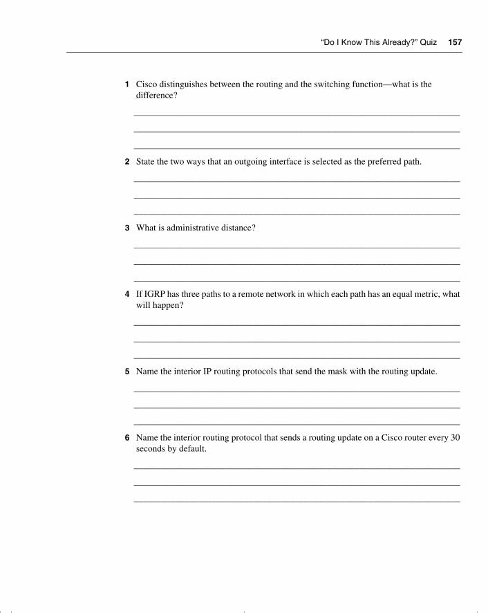
“Do I Know This Already?” Quiz 157
1 Cisco distinguishes between the routing and the switching function—what is the difference?
_______________________________________________________________________
_______________________________________________________________________
_______________________________________________________________________
2 State the two ways that an outgoing interface is selected as the preferred path.
_______________________________________________________________________
_______________________________________________________________________
_______________________________________________________________________
3 What is administrative distance?
_______________________________________________________________________
_______________________________________________________________________
_______________________________________________________________________
4 If IGRP has three paths to a remote network in which each path has an equal metric, what will happen?
_______________________________________________________________________
_______________________________________________________________________
_______________________________________________________________________
5 Name the interior IP routing protocols that send the mask with the routing update.
_______________________________________________________________________
_______________________________________________________________________
_______________________________________________________________________
6 Name the interior routing protocol that sends a routing update on a Cisco router every 30 seconds by default.
_______________________________________________________________________
_______________________________________________________________________
_______________________________________________________________________
chpt_01.book Page 157 Thursday, December 21, 2000 6:22 PM
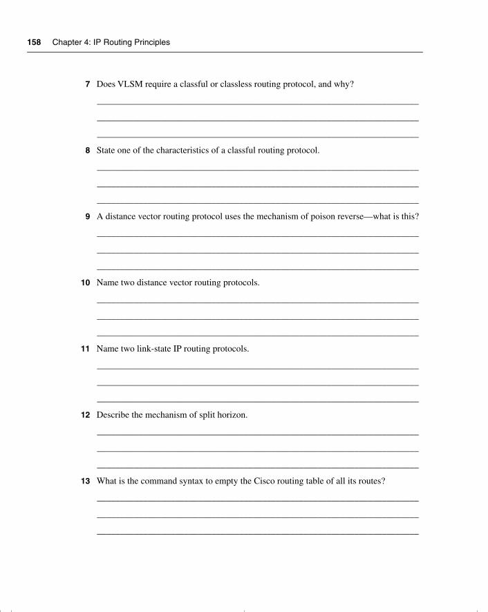
158 Chapter 4: IP Routing Principles
7 Does VLSM require a classful or classless routing protocol, and why?
______________________________________________________________________
______________________________________________________________________
______________________________________________________________________
8 State one of the characteristics of a classful routing protocol.
______________________________________________________________________
______________________________________________________________________
______________________________________________________________________
9 A distance vector routing protocol uses the mechanism of poison reverse—what is this?
______________________________________________________________________
______________________________________________________________________
______________________________________________________________________
10 Name two distance vector routing protocols.
______________________________________________________________________
______________________________________________________________________
______________________________________________________________________
11 Name two link-state IP routing protocols.
______________________________________________________________________
______________________________________________________________________
______________________________________________________________________
12 Describe the mechanism of split horizon.
______________________________________________________________________
______________________________________________________________________
______________________________________________________________________
13 What is the command syntax to empty the Cisco routing table of all its routes?
______________________________________________________________________
______________________________________________________________________
______________________________________________________________________
chpt_01.book Page 158 Thursday, December 21, 2000 6:22 PM
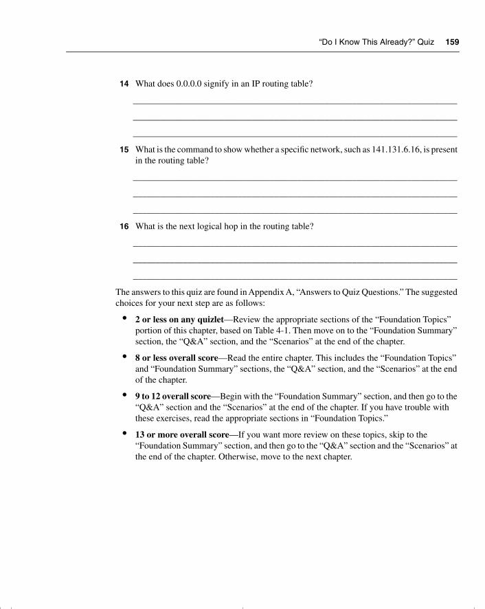
“Do I Know This Already?” Quiz 159
14 What does 0.0.0.0 signify in an IP routing table?
_______________________________________________________________________
_______________________________________________________________________
_______________________________________________________________________
15 What is the command to show whether a specific network, such as 141.131.6.16, is present in the routing table?
_______________________________________________________________________
_______________________________________________________________________
_______________________________________________________________________
16 What is the next logical hop in the routing table?
_______________________________________________________________________
_______________________________________________________________________
_______________________________________________________________________
The answers to this quiz are found in Appendix A, “Answers to Quiz Questions.” The suggested choices for your next step are as follows:
• 2 or less on any quizlet—Review the appropriate sections of the “Foundation Topics” portion of this chapter, based on Table 4-1. Then move on to the “Foundation Summary” section, the “Q&A” section, and the “Scenarios” at the end of the chapter.
• 8 or less overall score—Read the entire chapter. This includes the “Foundation Topics” and “Foundation Summary” sections, the “Q&A” section, and the “Scenarios” at the end of the chapter.
• 9 to 12 overall score—Begin with the “Foundation Summary” section, and then go to the “Q&A” section and the “Scenarios” at the end of the chapter. If you have trouble with these exercises, read the appropriate sections in “Foundation Topics.”
• 13 or more overall score—If you want more review on these topics, skip to the “Foundation Summary” section, and then go to the “Q&A” section and the “Scenarios” at the end of the chapter. Otherwise, move to the next chapter.
chpt_01.book Page 159 Thursday, December 21, 2000 6:22 PM
160 Chapter 4: IP Routing Principles
Foundation Topics
Introduction: What Is a Routing Protocol?The following case study illustrates some of the common concerns that a small company faces as it introduces routing into a switched/bridged network. This is a major transition and requires careful analysis to make the correct decisions regarding the choice of routing protocol as well as its implementation. This case study illustrates some of these issues with the Mental Merge company.
Case Study A small startup company, Mental Merge, the company seen in the last chapter, still has a flat network. It has deployed several switches and an addressing scheme that divides the network into logical networks. The company has deployed virtual LANs (VLANs) in some areas, but it is not routing between them. On the end stations that need to communicate with servers on another network, Mental Merge has a problem, and these clients are in the ridiculous situation of having to physically connect from a system connected to the appropriate network. Those systems that are on different logical networks, but in the same VLAN the end systems have, overcome the routing problem by making themselves their own default gateway.
Despite the implementation of VLANs, the traffic is increasing, and congestion is beginning to cause delays.
It is time to purchase routers, to install them, and to turn on routing.
It is important for Mental Merge to understand the routing process to install the routers in the right place and to ensure that the network addressing is correct. The company also needs to choose a routing protocol for IP.
This chapter deals with these subjects and considers the network for Mental Merge in the “Scenarios” section.
What Is a Routing Protocol?This section covers the definition, purpose, and operation of a routing protocol. It also covers the difference between a routing and routed protocol. It is necessary to understand the meaning of a protocol to understand exactly what a routing protocol is trying to achieve.
chpt_01.book Page 160 Thursday, December 21, 2000 6:22 PM
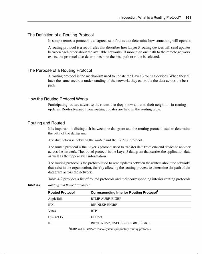
Introduction: What Is a Routing Protocol? 161
The Definition of a Routing Protocol In simple terms, a protocol is an agreed set of rules that determine how something will operate.
A routing protocol is a set of rules that describes how Layer 3 routing devices will send updates between each other about the available networks. If more than one path to the remote network exists, the protocol also determines how the best path or route is selected.
The Purpose of a Routing Protocol A routing protocol is the mechanism used to update the Layer 3 routing devices. When they all have the same accurate understanding of the network, they can route the data across the best path.
How the Routing Protocol WorksParticipating routers advertise the routes that they know about to their neighbors in routing updates. Routes learned from routing updates are held in the routing table.
Routing and Routed It is important to distinguish between the datagram and the routing protocol used to determine the path of the datagram.
The distinction is between the routed and the routing protocol.
The routed protocol is the Layer 3 protocol used to transfer data from one end device to another across the network. The routed protocol is the Layer 3 datagram that carries the application data as well as the upper-layer information.
The routing protocol is the protocol used to send updates between the routers about the networks that exist in the organization, thereby allowing the routing process to determine the path of the datagram across the network.
Table 4-2 provides a list of routed protocols and their corresponding interior routing protocols.
Table 4-2 Routing and Routed Protocols
Routed Protocol Corresponding Interior Routing Protocol1
AppleTalk RTMP, AURP, EIGRP
IPX RIP, NLSP, EIGRP
Vines RTP
DECnet IV DECnet
IP RIPv1, RIPv2, OSPF, IS-IS, IGRP, EIGRP1IGRP and EIGRP are Cisco Systems proprietary routing protocols.
chpt_01.book Page 161 Thursday, December 21, 2000 6:22 PM
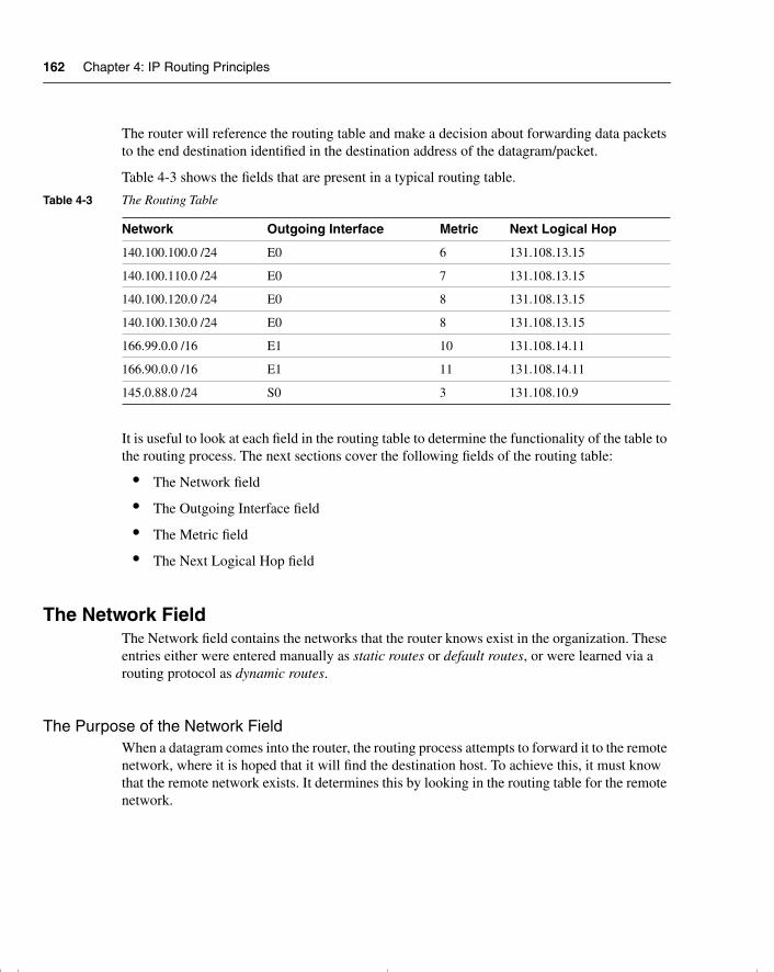
162 Chapter 4: IP Routing Principles
The router will reference the routing table and make a decision about forwarding data packets to the end destination identified in the destination address of the datagram/packet.
Table 4-3 shows the fields that are present in a typical routing table.
It is useful to look at each field in the routing table to determine the functionality of the table to the routing process. The next sections cover the following fields of the routing table:
• The Network field
• The Outgoing Interface field
• The Metric field
• The Next Logical Hop field
The Network FieldThe Network field contains the networks that the router knows exist in the organization. These entries either were entered manually as static routes or default routes, or were learned via a routing protocol as dynamic routes.
The Purpose of the Network FieldWhen a datagram comes into the router, the routing process attempts to forward it to the remote network, where it is hoped that it will find the destination host. To achieve this, it must know that the remote network exists. It determines this by looking in the routing table for the remote network.
Table 4-3 The Routing Table
Network Outgoing Interface Metric Next Logical Hop
140.100.100.0 /24 E0 6 131.108.13.15
140.100.110.0 /24 E0 7 131.108.13.15
140.100.120.0 /24 E0 8 131.108.13.15
140.100.130.0 /24 E0 8 131.108.13.15
166.99.0.0 /16 E1 10 131.108.14.11
166.90.0.0 /16 E1 11 131.108.14.11
145.0.88.0 /24 S0 3 131.108.10.9
chpt_01.book Page 162 Thursday, December 21, 2000 6:22 PM
Introduction: What Is a Routing Protocol? 163
How the Network Field Is UsedTypically, only the network portion of the address is stored in the table. Using the hierarchical strength of the addressing keeps the routing table small and the lookup short. The routing process makes a decision based on the longest match. This ensures that if VLSM has been deployed, the most specific network is chosen. Cisco IOS code mandates that the longest match can be a /32 or 255.255.255.255 mask. This is a match based on the full host address and is used in specific situations such as an OSPF environment. It is not encouraged as a common configuration because the size of the routing table grows rapidly.
The routes in the table are held in an order that speeds up the lookup process, ensuring that the routing decision is streamlined.
Later in the chapter, in the section “How the Routing Table Is Kept Current and Correct,” you will see how the networks are placed in the table and how path selection to a remote network is chosen.
The Outgoing Interface FieldThe Outgoing Interface is the interface on the router to which the routing process sends the datagram. This is the first step of its journey, the exit point of the router.
The Purpose of the Outgoing Interface FieldIt is necessary for the routing process to know which interface queue to use to send the outbound datagram. It also informs the administrator of the interface through which the network was heard in the routing update—or, more accurately, the interface through which the chosen network was heard.
In summary, the outgoing interface field in the routing table indicates the following:
• Which interface to send the datagram to
• Which interface the routing update came through
The Metric FieldThe metric is a value that is assigned to each path based on the criteria specified in the routing protocol. The Metric field is used to determine which path to use if there are multiple paths to the remote network. The metric used depends on the routing protocol.
This value is used to choose between different paths to the same destination network, to select the best path. If the values are the same, either the router selects the path that it heard first, or it uses both paths, sending the datagrams across each route.
chpt_01.book Page 163 Thursday, December 21, 2000 6:22 PM
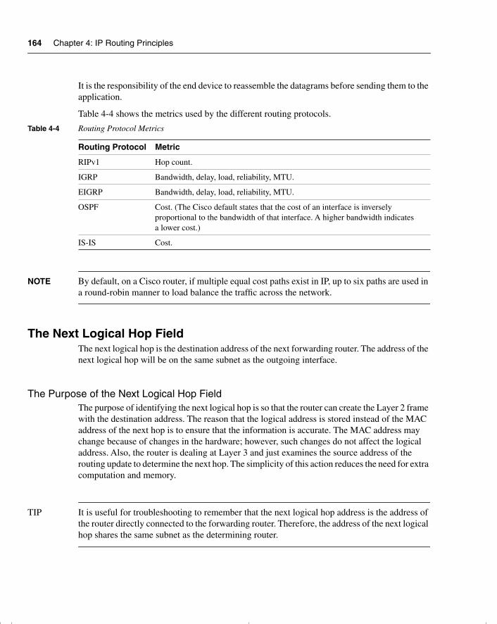
164 Chapter 4: IP Routing Principles
It is the responsibility of the end device to reassemble the datagrams before sending them to the application.
Table 4-4 shows the metrics used by the different routing protocols.
NOTE By default, on a Cisco router, if multiple equal cost paths exist in IP, up to six paths are used in a round-robin manner to load balance the traffic across the network.
The Next Logical Hop FieldThe next logical hop is the destination address of the next forwarding router. The address of the next logical hop will be on the same subnet as the outgoing interface.
The Purpose of the Next Logical Hop FieldThe purpose of identifying the next logical hop is so that the router can create the Layer 2 frame with the destination address. The reason that the logical address is stored instead of the MAC address of the next hop is to ensure that the information is accurate. The MAC address may change because of changes in the hardware; however, such changes do not affect the logical address. Also, the router is dealing at Layer 3 and just examines the source address of the routing update to determine the next hop. The simplicity of this action reduces the need for extra computation and memory.
TIP It is useful for troubleshooting to remember that the next logical hop address is the address of the router directly connected to the forwarding router. Therefore, the address of the next logical hop shares the same subnet as the determining router.
Table 4-4 Routing Protocol Metrics
Routing Protocol Metric
RIPv1 Hop count.
IGRP Bandwidth, delay, load, reliability, MTU.
EIGRP Bandwidth, delay, load, reliability, MTU.
OSPF Cost. (The Cisco default states that the cost of an interface is inversely proportional to the bandwidth of that interface. A higher bandwidth indicates a lower cost.)
IS-IS Cost.
chpt_01.book Page 164 Thursday, December 21, 2000 6:22 PM
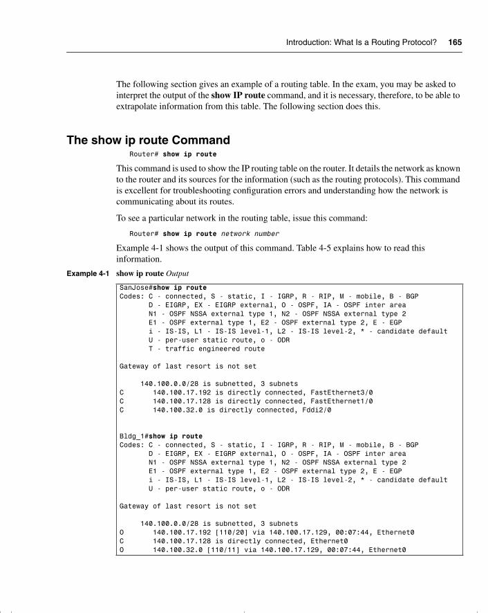
Introduction: What Is a Routing Protocol? 165
The following section gives an example of a routing table. In the exam, you may be asked to interpret the output of the show IP route command, and it is necessary, therefore, to be able to extrapolate information from this table. The following section does this.
The show ip route CommandRouter# show ip route
This command is used to show the IP routing table on the router. It details the network as known to the router and its sources for the information (such as the routing protocols). This command is excellent for troubleshooting configuration errors and understanding how the network is communicating about its routes.
To see a particular network in the routing table, issue this command:
Router# show ip route network number
Example 4-1 shows the output of this command. Table 4-5 explains how to read this information.
Example 4-1 show ip route Output
SanJose#show ip routeCodes: C - connected, S - static, I - IGRP, R - RIP, M - mobile, B - BGP D - EIGRP, EX - EIGRP external, O - OSPF, IA - OSPF inter area N1 - OSPF NSSA external type 1, N2 - OSPF NSSA external type 2 E1 - OSPF external type 1, E2 - OSPF external type 2, E - EGP i - IS-IS, L1 - IS-IS level-1, L2 - IS-IS level-2, * - candidate default U - per-user static route, o - ODR T - traffic engineered route
Gateway of last resort is not set
140.100.0.0/28 is subnetted, 3 subnetsC 140.100.17.192 is directly connected, FastEthernet3/0C 140.100.17.128 is directly connected, FastEthernet1/0C 140.100.32.0 is directly connected, Fddi2/0
Bldg_1#show ip routeCodes: C - connected, S - static, I - IGRP, R - RIP, M - mobile, B - BGP D - EIGRP, EX - EIGRP external, O - OSPF, IA - OSPF inter area N1 - OSPF NSSA external type 1, N2 - OSPF NSSA external type 2 E1 - OSPF external type 1, E2 - OSPF external type 2, E - EGP i - IS-IS, L1 - IS-IS level-1, L2 - IS-IS level-2, * - candidate default U - per-user static route, o - ODR
Gateway of last resort is not set
140.100.0.0/28 is subnetted, 3 subnetsO 140.100.17.192 [110/20] via 140.100.17.129, 00:07:44, Ethernet0C 140.100.17.128 is directly connected, Ethernet0O 140.100.32.0 [110/11] via 140.100.17.129, 00:07:44, Ethernet0
chpt_01.book Page 165 Thursday, December 21, 2000 6:22 PM
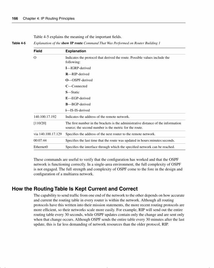
166 Chapter 4: IP Routing Principles
Table 4-5 explains the meaning of the important fields.
These commands are useful to verify that the configuration has worked and that the OSPF network is functioning correctly. In a single-area environment, the full complexity of OSPF is not engaged. The full strength and complexity of OSPF come to the fore in the design and configuration of a multiarea network.
How the Routing Table Is Kept Current and CorrectThe capability to send traffic from one end of the network to the other depends on how accurate and current the routing table in every router is within the network. Although all routing protocols have this written into their mission statements, the more recent routing protocols are more efficient, so their networks scale more easily. For example, RIP will send out the entire routing table every 30 seconds, while OSPF updates contain only the change and are sent only when that change occurs. Although OSPF sends the entire table every 30 minutes after the last update, this is far less demanding of network resources than the older protocol, RIP.
Table 4-5 Explanation of the show IP route Command That Was Performed on Router Building 1
Field Explanation
O Indicates the protocol that derived the route. Possible values include the following:
I—IGRP-derived
R—RIP-derived
O—OSPF-derived
C—Connected
S—Static
E—EGP-derived
B—BGP-derived
i—IS-IS-derived
140.100.17.192 Indicates the address of the remote network.
[110/20] The first number in the brackets is the administrative distance of the information source; the second number is the metric for the route.
via 140.100.17.129 Specifies the address of the next router to the remote network.
00:07:44 Specifies the last time that the route was updated in hours:minutes:seconds.
Ethernet0 Specifies the interface through which the specified network can be reached.
chpt_01.book Page 166 Thursday, December 21, 2000 6:22 PM
Introduction: What Is a Routing Protocol? 167
The accuracy of the table will be affected by how quickly it responds to changes in the network. These changes include the following:
• Learning new networks
• Learning a better path to an existing network
• Learning that a network is no longer available
• Learning an alternative route to a network
How each of these changes is achieved depends on the routing protocol.
Emptying the contents of the routing table and thus force the router to learn the information about the network is very useful in troubleshooting a network.
This command empties all the routes from the table:
Router# clear ip route *
This command removes the specific network from the table:
Router# clear ip route network
Switching Versus RoutingCisco makes a distinction between the routing function and the switching function of a router. The difference is simple: Two jobs within a router need to be done to move a datagram from an incoming interface to the outgoing interface.
The Routing FunctionThe routing function is responsible for learning the logical topology of the network and then making decisions based on that knowledge. The decisions determine whether the incoming datagram can be routed and, if so, how.
The decisions include these:
• Is the protocol stack configured on the router?
• Is there an entry for the remote network in the routing table?
• Is there a default network configured?
• Is the network reachable?
• Which is the best path to that remote network?
• Are there equal-cost multiple paths?
• To which outgoing interface(s) should the datagram(s) be queued?
chpt_01.book Page 167 Thursday, December 21, 2000 6:22 PM
168 Chapter 4: IP Routing Principles
The Switching FunctionThe switching function is concerned with moving data across the router. It is responsible for forwarding the datagram. Switching takes over after the routing decisions have been made. Although the router has lookups to make, the few decisions that need to be made are performed in hardware. Therefore, this function is very fast.
The switching function does the following:
• Checks the incoming frame for validity
• Checks whether the frame is addressed (at Layer 2) to the router
• Checks whether the frame is within the scope of the framing criteria (too big or too small)
• Checks whether the frame passes CRC
• Strips the Layer 2 header and trailer from the frame, and checks the destination address against the cache entries
• Creates the appropriate frame header and trailer (if there is an entry in cache for the destination address), and forwards the frame to the outbound interface queue
TIP Please note that the preceding section refers to the internals of the IOS, which is extremely complex. It has been described at the level required by the Routing exam. If live networks are to be designed and configured, it would be wise to understand in more depth some of the issues concerning caching and the placement of access lists. This information is readily available on the Cisco web page.
Functionality is broken into two components to ensure that the process is as fast as possible. After the routing decisions are made, the Cisco router caches the result, allowing subsequent datagrams to be switched.
The Routing/Switching Relationship in a Cisco RouterA packet transiting the router is accepted into the router if the frame header (of the frame in which the packet resides) contains the Layer 2 address of one of the router’s interfaces. If properly addressed, after the framing is checked, the frame and its content (the packet) are buffered, pending further processing. The buffering occurs in main memory or some other specialized memory location.
If the source and destination Layer 3 address of the datagram have not been seen by this router before, the datagram will be process switched (routed). This involves the following actions:
1 When a datagram is to be forwarded, a process initiates a lookup in this routing table and a decision about how the datagram should be forwarded.
chpt_01.book Page 168 Thursday, December 21, 2000 6:22 PM
Introduction: What Is a Routing Protocol? 169
2 The packet is then encapsulated.
3 If fast switching is enabled, the packet is then examined again, and an entry is put into a route cache. The entry in this cache consists of the following:
— An IP prefix
— The output interface
— The link-layer header to be used in forwarding the packet
On subsequent packets, if the IP destination matches a prefix found in the route cache, the packet is forwarded using this information. The routing function is not disturbed, nor are the CPU cycles required to feed this monster expended.
The type of route cache used depends on the hardware used. The caches available are called fast switching, autonomous switching, silicon switching, and Cisco Express Forwarding (CEF). If CEF switching is used, then the story changes again. With CEF switching, each card runs its own copy of the express forwarding and has its own copy of a forwarding information base (FIB). In the event of a routing change, this new entry is forwarded by the CPU to each separate line card.
Types of Routing ProtocolsAlthough the switching and routing functions within the router are set, there are many differences to be seen among the different routing protocols.
The routing protocols are essentially applications on the router. Their purpose is to ensure the correct and timely exchange of information about the network between the routers so that the routers can successfully perform the routing and switching functions described previously.
IP routing protocols can be divided into several distinct groups. The first is the difference between protocols that send the mask in the updates and the older protocols that do not. These are labeled classless and classful protocols, respectively.
Classful and Classless Routing ProtocolsClassful routing protocols do not carry the subnet or routing mask in the update. The older distance vector protocols tend to be classful. This incapability to carry the subnetting information leads to design constraints in the IP network.
Classful RoutingClassful IP routing protocols include RIPv1 and IGRP. The characteristics of a classful routing protocol are listed here:
• Summarization occurs at the network boundary.
chpt_01.book Page 169 Thursday, December 21, 2000 6:22 PM
170 Chapter 4: IP Routing Principles
• Routes exchanged between foreign networks are summarized to the NIC number network boundary.
• Within the same network (NIC number), subnet routes are exchanged by routers, without the mask.
• The subnet mask is assumed to be consistent for a NIC number used within a network, so all router interfaces must share the subnet mask for interfaces in the same NIC network.
• The utilization of address space may be inefficient.
• VLSM is not possible within the network.
Classless RoutingClassless routing protocols were designed to overcome the constraints listed previously. The routing protocols that can do this are OSPF, EIGRP, RIPv2, IS-IS, and BGP.
The characteristics of a classless routing protocol are listed here:
• Router interfaces within the same network can have different subnet masks (VLSM).
• Some of the classless routing protocols, including BGP-4 and RIP v2, support the use of classless interdomain routing (CIDR).
• Some routes can be summarized within the major NIC number. This is done manually.
NOTE BGP-4 and EIGRP summarizes at the network boundary automatically. Summarization within the NIC number boundary must be configured manually.
The distinctions of classless and classful are important between routing protocols. Another important distinction is based on the technology that they employ.
IP routing protocols use two main technologies: link-state and distance vector technologies. These are discussed next.
Distance Vector and Link-State Routing ProtocolsDistance vector protocols are the earliest protocols, and they include RIPv1 and IGRP. These protocols are classful protocols, but RIPv2 and EIGRP are examples of classless routing protocols.
chpt_01.book Page 170 Thursday, December 21, 2000 6:22 PM
Distance Vector and Link-State Routing Protocols 171
Distance vector protocols were designed for small networks. As the networks started to expand, enhancements were made to the distance vector protocols (RIPv2 and IGRP). At the same time, link-state protocols such as OSPF were introduced
Distance Vector Routing ProtocolsDistance vector protocols send periodic updates. These updates are sent to directly connected neighbors. The update is periodic because it waits for the timer to expire before it sends an update. After receiving a neighbor’s routing table, the router updates its table and sends the modified table in subsequent updates. This is the reason that distance vector routing protocols are said to be “routing by rumor.”
The purpose of the protocol is to provide accurate, loop-free information to the routers. The update affects the entire routing table, excluding those networks that were learned through the interface through which the update is being sent. This is in accordance to the split horizon rule; this reduces network overhead and also prevents information from traveling in circles through the network, which can create routing loops.
To prevent routing loops, distance vector routing protocols employ the following techniques, which are described in more depth in the section on RIPv1:
• Split horizon
• Count to infinity
• Poison reverse
• Hold-down
• Triggered updates
• Aging of routes from the routing table
NOTE Although EIGRP is defined by Cisco as an advanced distance vector routing protocol, it has adopted some of the link-state characteristics in favor of the distance vector solution. It does not use either count to infinity or hold-down timers.
The Distance Vector Routing MetricsThe metric used by distance vector protocols is often stated as being distance measured in the number of hand-off points or hops (routers) encountered on the way to the end device. Cisco defines IGRP and EIGRP as distance vector routing protocols. This muddies the original definition because IGRP and EIGRP use a composite and complex metric.
chpt_01.book Page 171 Thursday, December 21, 2000 6:22 PM
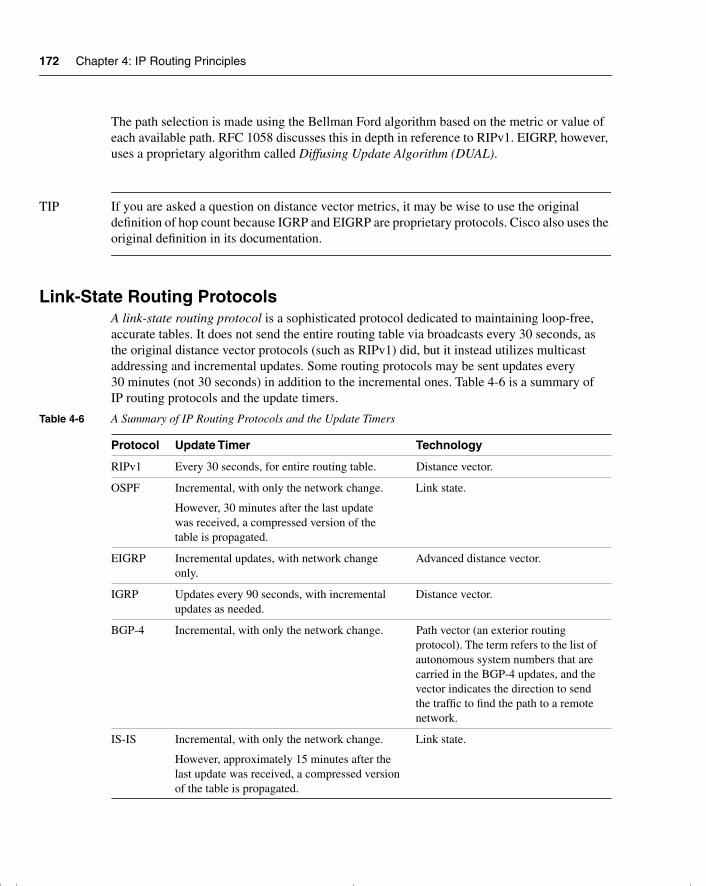
172 Chapter 4: IP Routing Principles
The path selection is made using the Bellman Ford algorithm based on the metric or value of each available path. RFC 1058 discusses this in depth in reference to RIPv1. EIGRP, however, uses a proprietary algorithm called Diffusing Update Algorithm (DUAL).
TIP If you are asked a question on distance vector metrics, it may be wise to use the original definition of hop count because IGRP and EIGRP are proprietary protocols. Cisco also uses the original definition in its documentation.
Link-State Routing ProtocolsA link-state routing protocol is a sophisticated protocol dedicated to maintaining loop-free, accurate tables. It does not send the entire routing table via broadcasts every 30 seconds, as the original distance vector protocols (such as RIPv1) did, but it instead utilizes multicast addressing and incremental updates. Some routing protocols may be sent updates every 30 minutes (not 30 seconds) in addition to the incremental ones. Table 4-6 is a summary of IP routing protocols and the update timers.
Table 4-6 A Summary of IP Routing Protocols and the Update Timers
Protocol Update Timer Technology
RIPv1 Every 30 seconds, for entire routing table. Distance vector.
OSPF Incremental, with only the network change.
However, 30 minutes after the last update was received, a compressed version of the table is propagated.
Link state.
EIGRP Incremental updates, with network change only.
Advanced distance vector.
IGRP Updates every 90 seconds, with incremental updates as needed.
Distance vector.
BGP-4 Incremental, with only the network change. Path vector (an exterior routing protocol). The term refers to the list of autonomous system numbers that are carried in the BGP-4 updates, and the vector indicates the direction to send the traffic to find the path to a remote network.
IS-IS Incremental, with only the network change.
However, approximately 15 minutes after the last update was received, a compressed version of the table is propagated.
Link state.
chpt_01.book Page 172 Thursday, December 21, 2000 6:22 PM
Distance Vector and Link-State Routing Protocols 173
The Meaning of Link StateAs with a distance vector router, information is exchanged only with its directly connected neighbor. Unlike distance vector protocols, the information concerns only the local links (not the routes) connected to the router, and these links are propagated, unchanged, to every other router in the network. Therefore, every router has the same image of the network, created from the original updates from every other router in the network.
The purpose of link-state routers is to reduce the network overhead of the routing updates that are both current and thus accurate, allowing it to scale to large networks.
Sending an update about links is more efficient than sending data about routes because one link may effect many routes. Sending the links allows the routers to compute the routes that may be affected. The resources used are router CPU rather than network bandwidth.
Learning About the Network A link-state routing protocol develops a relationship with an adjacent router, one that is on the same physical network. The two also must have the same subnet mask and have the same hello timers. The routing protocol develops and maintains the relationship by sending a simple message across the medium. When another router replies, it is identified as a neighbor for the routing process. This neighbor relationship is maintained as long as the simple message (Hello protocol) is received. Because the neighbor relationship is continuous, information can be exchanged between the routing processes quickly and efficiently. Therefore, changes in the network are realized very quickly.
Link-state routing protocols are used in larger networks because the method that they use to update the routing tables requires fewer network resources.
Learning About a Change in the Network A router knows very quickly whether the neighbor, which may also be the next logical hop, is dead because the router no longer receives Hello protocol messages.
The routing process sends out a message immediately when it identifies a problem, without waiting for the update timer to expire. This is known as an incremental update. The update contains only the relevant information. The router also remains silent if there is no change in the network.
The incremental update improves convergence time and also reduces the amount of information that needs to be sent across the network. The network overhead on the physical media is eased, and the potential throughput of the network is improved.
chpt_01.book Page 173 Thursday, December 21, 2000 6:22 PM
174 Chapter 4: IP Routing Principles
Updating Local Network TablesA link-state protocol holds a topology map of the network and can easily update the map and routing table database, via the incremental updates. In OSPF, these are called link-state advertisements (LSAs). After an update is received and forwarded, the router will compute a new topology map and, from this, a new path. It uses the Dijkstra algorithm to achieve this new understanding of the network.
Path SelectionThe metric that is used is stated as cost, although many vendors supply a default that may be overridden manually. This is true of Cisco’s implementation of OSPF, which uses bandwidth and delay as its default.
Examples of link-state routing protocols for IP are OSPF and IS-IS.
Another distinction that needs to be made between routing protocols is the difference between interior and exterior protocols. Interior protocols are those that update routers within an organization. Exterior protocols are those that update routers that connect different organizations to each other or to the Internet.
Interior and Exterior Routing ProtocolsRouting protocols that operate within an organization are referred to as interior routing protocols (for example, RIPv1, IGRP, EIGRP, OSPF, and IS-IS).
Interior Routing ProtocolsThe boundaries of the organization are defined as the autonomous system. The unique number assigned to the autonomous system then identifies the organization. The autonomous system number may be viewed as another layer of hierarchy in the IP addressing scheme because the number can represent a collection of NIC numbers.
Exterior Routing ProtocolsRouting protocols that exchange routing information between organizations are known as exterior routing protocols. Exterior routing protocols are highly complex. The complexity arises from the need to determine policies between different organizations. Border Gateway Protocol Version 4 (BGP-4) is an example of an exterior gateway protocol.
chpt_01.book Page 174 Thursday, December 21, 2000 6:22 PM
RIP Version 1 175
NOTE This next section deals briefly with an older distance vector routing protocol, RIP; an improved distance vector routing protocol, IGRP; and a link-state routing protocol, OSPF. RIPv1 and IGRP are discussed here because they are not dealt with in the subsequent chapters. Although OSPF is dealt with in greater detail in the following chapters, it lends an interesting contrast to the two distance vector protocols.
RIP Version 1Routing Information Protocol version 1 (RIPv1) is a simple routing protocol and, as such, works well in a small environment. As a distance vector routing protocol, it sends updates every 30 seconds. These updates comprise the entire routing table.
RIPv1 will support the following:
• Count to infinity—A router advertising networks heard from a neighboring router back to the same neighboring router could create a loop. In repeating networks to the router that informed the routing table, when a network goes down, each router may believe that there is an existing path through its neighbor. This problem is limited because each router increments the hop count before it sends out the update. When the hop count reaches 16, the network is rejected as unreachable because the diameter of a RIPv1 network cannot be greater than 15. This is called counting to infinity, where infinity equals 16. Although the liability is controlled, it will still slow convergence of the network.
• Split horizon—This is a mechanism to prevent loops and, thereby, the necessity of count to infinity. The routing process will not send networks learned through an interface in an update out that interface. It will not repeat information to the router that told of the networks.
• Split horizon with poison reverse—Split horizon on its own may not prevent loops. Poison reverse includes all the networks that have been learned from the neighbor, but it sets the metric to infinity (16). By changing the metric value to 16, the networks are reported to be unreachable. It acknowledges the network but denies a valid path. Although this increases network overhead by increasing the update size, it can prevent loops.
• Holddown—After deciding that a network in the routing table is no longer valid, the routing process waits for three routing updates (by default) before it believes a routing update with a less-favorable metric. Again, this is to prevent routing loops from generating false information throughout the network.
• Triggered updates—As soon as a routing process changes a metric for a network in its routing table, it sends an update. This informs the other routers immediately. If there is a problem in the network, all the affected routers go into holddown immediately instead of waiting for the periodic timer. This increases convergence and helps prevent loops.
chpt_01.book Page 175 Thursday, December 21, 2000 6:22 PM
176 Chapter 4: IP Routing Principles
• Load balancing—If the routing process sees multiple paths of equal cost to a remote network, it distributes the routed (datagram) traffic evenly among the paths. It will allocate datagrams to the different paths on a round-robin basis.
WARNING Because the metric used is hop count, one path may become saturated. A 56-kbps line and a 100-Mbps Fast Ethernet line may both offer paths of equal hop count; dividing the user traffic between them, but, may not optimize the bandwidth of the network.
Cisco has implemented all the preceding options, which are defined in RFC 1058.
RIPv1 is useful in small networks and is distributed with Berkeley Standard Distribution (BSD), which makes it widely available. It may not be suitable for large environments, however, because the protocol was never designed with the expectation of being used in huge organizations.
As the network grows, problems will be seen with applications timing out and congestion occurring on the network as the routers fail to adapt quickly to changes. When there has been a change in the network, the time that it takes for every router to register that change is known as the convergence time. The longer this timer takes, the greater the likelihood of problems on the network. Therefore, it is necessary either to contain the growth of the network or to use a routing protocol that scales to a larger size. OSPF is designed to scale and has the added advantage of being defined by the Internet Engineering Task Force (IETF), making it an industry standard in the public domain.
IGRPIGRP is a distance vector routing protocol created by Cisco Systems in the mid-1980s. It is a distance vector routing protocol, but because it is proprietary, it has the advantage of being capable of improving many of the elements seen in RIPv1, including incremental updates, fewer network resources to maintain the routing protocol, a more complex and efficient metric, and no limitation in diameter of the network because of hop count.
Although IGRP can streamline its operation because it does not have to be all things to all people, it can be implemented only on Cisco routers. It is very efficient at sharing its information with other routing protocols, using redistribution.
NOTE It is unlikely that there will be direct questions on either RIPv1 or IGRP. There will be questions on the distance vector and link-state protocols. RIPv1 and IGRP are discussed here only as illustrations of distance vector protocols.
chpt_01.book Page 176 Thursday, December 21, 2000 6:22 PM
OSPF 177
IGRP has the following characteristics of a distance vector routing protocol:
• Periodic updates
• Broadcasting updates
• Full routing table updates
• Count to infinity
• Split horizon
• Triggered updates with route poisoning
• Load balancing on equal paths (up to four, by default)
• Bellman Ford routing algorithm
It differs from RIPv1 in the following ways:
• The metric is a composite calculated from bandwidth, delay, loading, reliability, and MTU. In fact, although MTU was originally designed as part of the metric, it is tracked but not used in the calculation. It is possible to configure the use of all the calculated elements of the metric. If these are not configured, the system will use bandwidth and delay by default.
• The hop count is 100, configurable to 255 (although this is not used as a metric, but to age out datagrams).
• The update timer is set by default to 90 seconds (three times that of RIPv1).
• Unequal load sharing occurs on multiple paths.
• A more efficient packet structure is used.
• Autonomous systems (AS) are used to allow multiple processes within a routing domain, which allows the network to scale.
OSPF
NOTE OSPF is dealt with in great depth in the following chapter. It is considered here so that general comparisons may be made between the array of different IP routing protocols and the technologies underlying them. Unfortunately, this means that there may be some level of repetition between the chapters. Subheadings have been carefully worded so that the reader can read relevant information in context while avoiding repetition.
chpt_01.book Page 177 Thursday, December 21, 2000 6:22 PM
178 Chapter 4: IP Routing Principles
OSPF is an improvement on RIPv1 for large networks because of the following reasons:
• It utilizes bandwidth more efficiently, sending incremental updates.
• The updates are not broadcast as in RIPv1 but are directed to multicast addresses 224.0.0.5 and 224.0.0.6.
• It propagates changes in the network more quickly, with incremental updates and neighbor relationships.
• It is not limited in size by a maximum hop count of 15.
• It allows for variation in network size throughout the organization, using VLSM.
• It has security options defined in the MD5 specification.
• The metric may be defined manually, allowing for greater sophistication in the path determination.
• It is more responsive to network changes, is flexible in network addressing and design, and scales to a larger size.
The following sections discuss these key points in detail.
Key Attributes of OSPFOSPF is designed to offer the greatest flexibility for every situation. As an open standard, it is required to offer interoperability in conjunction with this flexibility, while allowing the network to grow. These requirements make OSPF a highly complex routing protocol.
To understand this complexity, it is useful to identify the main characteristics of OSPF. These key attributes of OSPF include the following:
• Maintaining a connection-oriented relationship with other routers on the same physical segment. These are known as adjacent neighbors. This is a TCP connection maintained by keepalives.
• Sending the minimum amount of information in an incremental update when there has been a change in the network. This allows for fast network convergence.
• Adding another level of hierarchy to the IP address, by designing networks into areas.
• Using VLSM and summarization.
• Assigning specific functionality to different routers to streamline the process of communication change in the network.
• Operating within an organization as an interior routing protocol.
chpt_01.book Page 178 Thursday, December 21, 2000 6:22 PM
OSPF 179
Path Selection Between Routing ProtocolsClearly there are many IP routing protocols from which to choose. It is better if a single routing protocol can be chosen because this gives a consistency that relates directly to the strength of the network. It complicates the network to have more than a single routing protocol attempting to perform the same job. The routing table, in particular, sometimes deals with confusion in how to select one path to place into the routing table.
When more than one routing protocol is running on the router, the routing process must make a decision to have one entry per network in the routing table. The choice cannot be based on the metric because metrics differ between protocols. Instead, another method, called administrative distance, was devised to solve the problem.
NOTE When it is necessary to have more than one routing protocol within an organization, redistribution is configured. However, the router that is responsible for redistribution will have more than one routing protocol informing the routing table.
Administrative DistanceThe administrative distance will select one path to enter the routing table from several paths offered by multiple routing protocols.
In Figure 4-2, for example, both RIP and EIGRP have paths to the network 140.100.6.0. RIP is offering a metric of 2 hops, and EIGRP is tendering a metric of 768. Without redistribution, no conversion or choice is possible because there is no similar criteria for distinguishing the two paths. Therefore, the metric is ignored, and the administrative distance is used to make the selection.
In Figure 4-2, despite the speed of Frame Relay being set at 56 kbps as opposed to the 100 Mbps of FDDI, Router D would select the Frame Relay path based on administrative distance. In this case, manually configuring the administrative distance on Router D would be advisable.
Administrative distance is a rather arbitrary set of values placed on the different sources of routing information. The defaults can be changed, but care should be taken when subverting the natural path selection, and any manual configuration must be done with careful reference to the network design of the organization and its traffic flow.
Administrative distance reflects the preferred choice. The defaults are listed in Table 4-7.
chpt_01.book Page 179 Thursday, December 21, 2000 6:22 PM
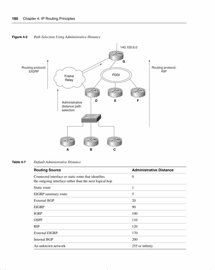
180 Chapter 4: IP Routing Principles
Figure 4-2 Path Selection Using Administrative Distance
Table 4-7 Default Administrative Distance
Routing Source Administrative Distance
Connected interface or static route that identifies the outgoing interface rather than the next logical hop
0
Static route 1
EIGRP summary route 5
External BGP 20
EIGRP 90
IGRP 100
OSPF 110
RIP 120
External EIGRP 170
Internal BGP 200
An unknown network 255 or infinity
Routing protocol:EIGRP
Routing protocol:RIP
Administrativedistance pathselection
FDDIFrameRelay
140.100.6.0
A B C
D E F
G
chpt_01.book Page 180 Thursday, December 21, 2000 6:22 PM
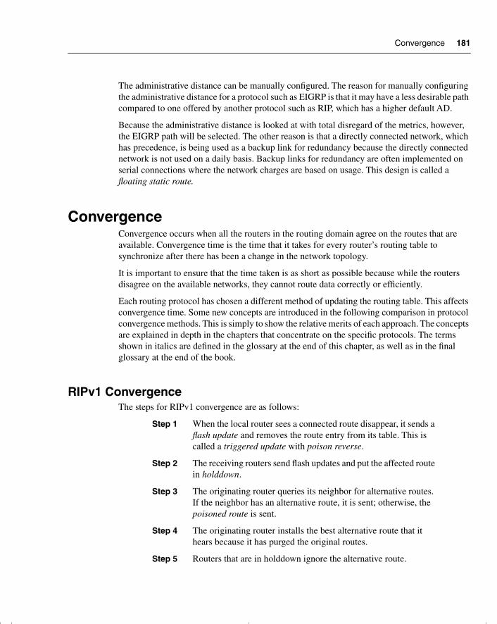
Convergence 181
The administrative distance can be manually configured. The reason for manually configuring the administrative distance for a protocol such as EIGRP is that it may have a less desirable path compared to one offered by another protocol such as RIP, which has a higher default AD.
Because the administrative distance is looked at with total disregard of the metrics, however, the EIGRP path will be selected. The other reason is that a directly connected network, which has precedence, is being used as a backup link for redundancy because the directly connected network is not used on a daily basis. Backup links for redundancy are often implemented on serial connections where the network charges are based on usage. This design is called a floating static route.
ConvergenceConvergence occurs when all the routers in the routing domain agree on the routes that are available. Convergence time is the time that it takes for every router’s routing table to synchronize after there has been a change in the network topology.
It is important to ensure that the time taken is as short as possible because while the routers disagree on the available networks, they cannot route data correctly or efficiently.
Each routing protocol has chosen a different method of updating the routing table. This affects convergence time. Some new concepts are introduced in the following comparison in protocol convergence methods. This is simply to show the relative merits of each approach. The concepts are explained in depth in the chapters that concentrate on the specific protocols. The terms shown in italics are defined in the glossary at the end of this chapter, as well as in the final glossary at the end of the book.
RIPv1 ConvergenceThe steps for RIPv1 convergence are as follows:
Step 1 When the local router sees a connected route disappear, it sends a flash update and removes the route entry from its table. This is called a triggered update with poison reverse.
Step 2 The receiving routers send flash updates and put the affected route in holddown.
Step 3 The originating router queries its neighbor for alternative routes. If the neighbor has an alternative route, it is sent; otherwise, the poisoned route is sent.
Step 4 The originating router installs the best alternative route that it hears because it has purged the original routes.
Step 5 Routers that are in holddown ignore the alternative route.
chpt_01.book Page 181 Thursday, December 21, 2000 6:22 PM
182 Chapter 4: IP Routing Principles
Step 6 When the other routers emerge from holddown, they will accept the alternative route.
Step 7 Convergence takes the time for detection, plus holddown, plus the number of routing updates (equal to the hop-count diameter of the network). This could take a long time.
IGRP ConvergenceThe steps for IGRP convergence are as follows:
Step 1 When the local router sees a connected route disappear, it sends a flash update and removes the route entry from its table. This is called a triggered update with poison reverse.
Step 2 The receiving routers send flash updates and put the affected route in holddown.
Step 3 The originating router queries its neighbor for alternative routes. If the neighbor has an alternative route, it is sent; otherwise, the poisoned route is sent.
Step 4 The originating router installs the best alternative route that it hears because it has purged the original routes. It sends a new flash update. This is either the routing table, with or without the network available, stating the higher metric.
Step 5 Routers that are in holddown ignore the alternative route.
Step 6 When the routers come out of holddown, they accept the alternative route.
When the other routers emerge from holddown, they will accept the alternative route.
Step 7 Convergence takes the time for detection, plus holddown, plus the number of routing updates (equal to the hop-count diameter of the network). Because the update timer is 90 seconds, this could take a very long time.
EIGRP ConvergenceThe steps for EIGRP convergence are as follows:
Step 1 When the local router sees a connected route disappear, it checks the topology table for a feasible successor.
Step 2 If no feasible successor exists, it moves into active state.
chpt_01.book Page 182 Thursday, December 21, 2000 6:22 PM
Conclusion 183
Step 3 The originating router queries its neighbor for alternative routes, the receiving router acknowledges.
Step 4 If an alternative exists, it is sent.
Step 5 If the router receives an acceptable successor, it adds the route to the table.
Step 6 A flash update of the path with the higher metric is sent out.
Step 7 Updates are acknowledged.
Convergence is very quick because it is the detection time, plus query, reply, and update time. If there is a feasible successor, then convergence is almost instantaneous.
OSPF ConvergenceThe steps for OSPF convergence are as follows:
Step 1 When a router detects a link failure, an LSA is sent to its neighbors. If the router is on a multiaccess link, then the update is sent to the DR and BDR, not to all neighbors.
Step 2 The path is removed from the originating router’s tables.
Step 3 On receipt of the LSA, all routers update the topology table and flood the LSA out its interfaces.
Step 4 The Dijkstra algorithm is run to rebuild the routing table.
Convergence is detection time, plus LSA flooding, plus 5 seconds before computing the topology table. This comes to a few seconds. If convergence is deemed to be the topology table being updated, this could take longer.
ConclusionThis chapter reviewed IP routing protocols. It has shown how to untangle the various categories of routing protocols, how to analyze the IP routing table, and how to understand how routing decisions are made.
This information is crucial to the Routing exam because it is essentially an exam on IP routing. This chapter is a foundation to the other chapters, which deal in depth with particular technologies.
chpt_01.book Page 183 Thursday, December 21, 2000 6:22 PM
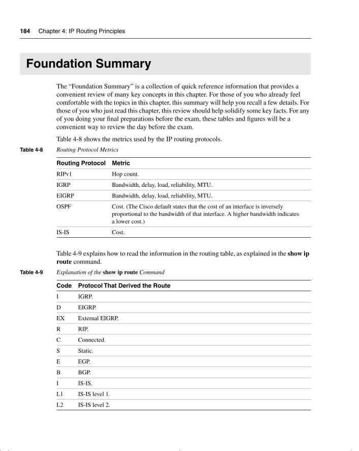
184 Chapter 4: IP Routing Principles
Foundation Summary
The “Foundation Summary” is a collection of quick reference information that provides a convenient review of many key concepts in this chapter. For those of you who already feel comfortable with the topics in this chapter, this summary will help you recall a few details. For those of you who just read this chapter, this review should help solidify some key facts. For any of you doing your final preparations before the exam, these tables and figures will be a convenient way to review the day before the exam.
Table 4-8 shows the metrics used by the IP routing protocols.
Table 4-9 explains how to read the information in the routing table, as explained in the show ip route command.
Table 4-8 Routing Protocol Metrics
Routing Protocol Metric
RIPv1 Hop count.
IGRP Bandwidth, delay, load, reliability, MTU.
EIGRP Bandwidth, delay, load, reliability, MTU.
OSPF Cost. (The Cisco default states that the cost of an interface is inversely proportional to the bandwidth of that interface. A higher bandwidth indicates a lower cost.)
IS-IS Cost.
Table 4-9 Explanation of the show ip route Command
Code Protocol That Derived the Route
I IGRP.
D EIGRP.
EX External EIGRP.
R RIP.
C Connected.
S Static.
E EGP.
B BGP.
I IS-IS.
L1 IS-IS level 1.
L2 IS-IS level 2.
chpt_01.book Page 184 Thursday, December 21, 2000 6:22 PM
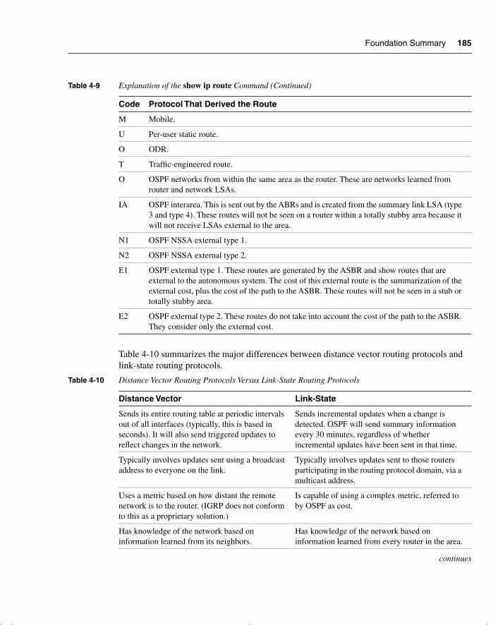
Foundation Summary 185
Table 4-10 summarizes the major differences between distance vector routing protocols and link-state routing protocols.
M Mobile.
U Per-user static route.
O ODR.
T Traffic-engineered route.
O OSPF networks from within the same area as the router. These are networks learned from router and network LSAs.
IA OSPF interarea. This is sent out by the ABRs and is created from the summary link LSA (type 3 and type 4). These routes will not be seen on a router within a totally stubby area because it will not receive LSAs external to the area.
N1 OSPF NSSA external type 1.
N2 OSPF NSSA external type 2.
E1 OSPF external type 1. These routes are generated by the ASBR and show routes that are external to the autonomous system. The cost of this external route is the summarization of the external cost, plus the cost of the path to the ASBR. These routes will not be seen in a stub or totally stubby area.
E2 OSPF external type 2. These routes do not take into account the cost of the path to the ASBR. They consider only the external cost.
Table 4-10 Distance Vector Routing Protocols Versus Link-State Routing Protocols
Distance Vector Link-State
Sends its entire routing table at periodic intervals out of all interfaces (typically, this is based in seconds). It will also send triggered updates to reflect changes in the network.
Sends incremental updates when a change is detected. OSPF will send summary information every 30 minutes, regardless of whether incremental updates have been sent in that time.
Typically involves updates sent using a broadcast address to everyone on the link.
Typically involves updates sent to those routers participating in the routing protocol domain, via a multicast address.
Uses a metric based on how distant the remote network is to the router. (IGRP does not conform to this as a proprietary solution.)
Is capable of using a complex metric, referred to by OSPF as cost.
Has knowledge of the network based on information learned from its neighbors.
Has knowledge of the network based on information learned from every router in the area.
continues
Table 4-9 Explanation of the show ip route Command (Continued)
Code Protocol That Derived the Route
chpt_01.book Page 185 Thursday, December 21, 2000 6:22 PM
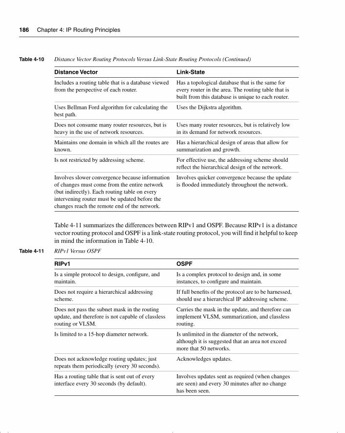
186 Chapter 4: IP Routing Principles
Table 4-11 summarizes the differences between RIPv1 and OSPF. Because RIPv1 is a distance vector routing protocol and OSPF is a link-state routing protocol, you will find it helpful to keep in mind the information in Table 4-10.
Includes a routing table that is a database viewed from the perspective of each router.
Has a topological database that is the same for every router in the area. The routing table that is built from this database is unique to each router.
Uses Bellman Ford algorithm for calculating the best path.
Uses the Dijkstra algorithm.
Does not consume many router resources, but is heavy in the use of network resources.
Uses many router resources, but is relatively low in its demand for network resources.
Maintains one domain in which all the routes are known.
Has a hierarchical design of areas that allow for summarization and growth.
Is not restricted by addressing scheme. For effective use, the addressing scheme should reflect the hierarchical design of the network.
Involves slower convergence because information of changes must come from the entire network (but indirectly). Each routing table on every intervening router must be updated before the changes reach the remote end of the network.
Involves quicker convergence because the update is flooded immediately throughout the network.
Table 4-11 RIPv1 Versus OSPF
RIPv1 OSPF
Is a simple protocol to design, configure, and maintain.
Is a complex protocol to design and, in some instances, to configure and maintain.
Does not require a hierarchical addressing scheme.
If full benefits of the protocol are to be harnessed, should use a hierarchical IP addressing scheme.
Does not pass the subnet mask in the routing update, and therefore is not capable of classless routing or VLSM.
Carries the mask in the update, and therefore can implement VLSM, summarization, and classless routing.
Is limited to a 15-hop diameter network. Is unlimited in the diameter of the network, although it is suggested that an area not exceed more that 50 networks.
Does not acknowledge routing updates; just repeats them periodically (every 30 seconds).
Acknowledges updates.
Has a routing table that is sent out of every interface every 30 seconds (by default).
Involves updates sent as required (when changes are seen) and every 30 minutes after no change has been seen.
Table 4-10 Distance Vector Routing Protocols Versus Link-State Routing Protocols (Continued)
Distance Vector Link-State
chpt_01.book Page 186 Thursday, December 21, 2000 6:22 PM
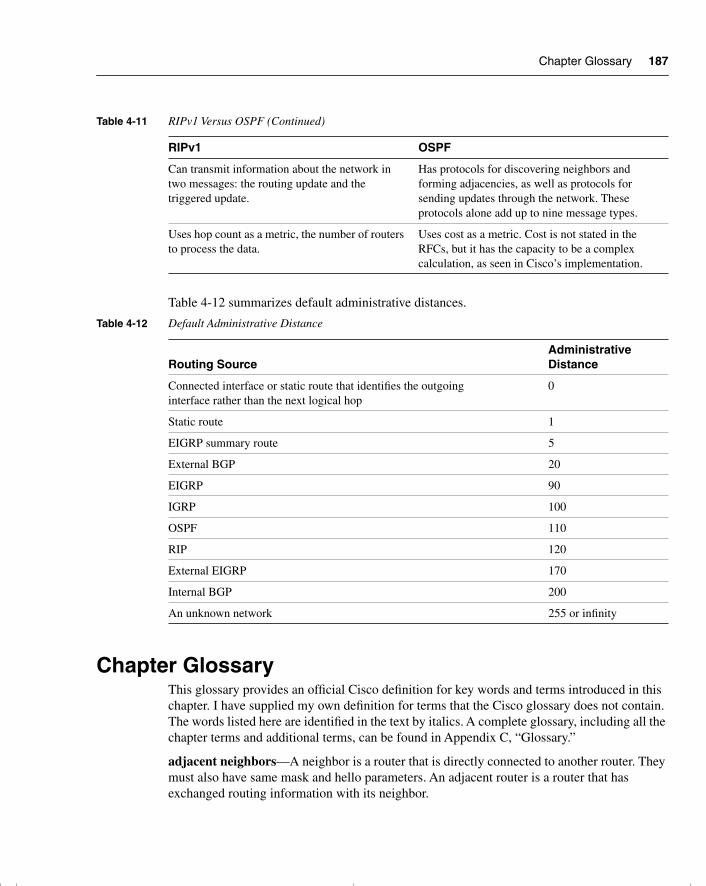
Chapter Glossary 187
Table 4-12 summarizes default administrative distances.
Chapter GlossaryThis glossary provides an official Cisco definition for key words and terms introduced in this chapter. I have supplied my own definition for terms that the Cisco glossary does not contain. The words listed here are identified in the text by italics. A complete glossary, including all the chapter terms and additional terms, can be found in Appendix C, “Glossary.”
adjacent neighbors—A neighbor is a router that is directly connected to another router. They must also have same mask and hello parameters. An adjacent router is a router that has exchanged routing information with its neighbor.
Can transmit information about the network in two messages: the routing update and the triggered update.
Has protocols for discovering neighbors and forming adjacencies, as well as protocols for sending updates through the network. These protocols alone add up to nine message types.
Uses hop count as a metric, the number of routers to process the data.
Uses cost as a metric. Cost is not stated in the RFCs, but it has the capacity to be a complex calculation, as seen in Cisco’s implementation.
Table 4-12 Default Administrative Distance
Routing SourceAdministrative Distance
Connected interface or static route that identifies the outgoing interface rather than the next logical hop
0
Static route 1
EIGRP summary route 5
External BGP 20
EIGRP 90
IGRP 100
OSPF 110
RIP 120
External EIGRP 170
Internal BGP 200
An unknown network 255 or infinity
Table 4-11 RIPv1 Versus OSPF (Continued)
RIPv1 OSPF
chpt_01.book Page 187 Thursday, December 21, 2000 6:22 PM
188 Chapter 4: IP Routing Principles
area—A logical set of network segments and their attached devices. Areas are usually connected to other areas via routers, making up a single autonomous system. See also AS. Used in DECnet, IS-IS, and OSPF.
autonomous switching—Feature on Cisco routers that provides faster packet processing by allowing the ciscoBus to switch packets independently without interrupting the system processor.
autonomous system—A collection of networks under a common administration sharing a common routing strategy. Autonomous systems may be subdivided into areas.
Berkeley Standard Distribution (BSD)—Term used to describe any of a variety of UNIX-type operating systems based on the UC Berkeley BSD operating system.
Cisco Express Forwarding (CEF)—Advanced, Layer 3 IP switching technology. CEF optimizes network performance and scalability for networks with large and dynamic traffic patterns, such as the Internet, on networks characterized by intensive web-based applications or interactive sessions.
classful routing protocol—A protocol that does not carry the subnet mask. A distance vector routing protocol that will not allow VLSM or route summarization.
classless routing protocol—A routing protocol that carries the subnet mask in the routing update. This allows the implementation of VLSM and summarization.
convergence—Speed and capability of a group of internetworking devices running a specific routing protocol to agree on the topology of an internetwork after a change in that topology.
count to infinity—Problem that can occur in routing algorithms that are slow to converge, in which routers continuously increment the hop count to particular networks. Typically, some arbitrary hop count limit is imposed to prevent this problem.
default routes—A route that should be used if the destination network is not present in the routing table.
Diffusing Update Algorithm (DUAL)—A convergence algorithm used in Enhanced IGRP that provides loop-free operation at every instant throughout a route computation. This allows routers involved in a topology change to synchronize at the same time, while not involving routers that are unaffected by the change.
Dijkstra algorithm—Routing algorithm that iterates on length of path to determine a shortest-path spanning tree. Commonly used in link-state routing algorithms. Sometimes called shortest path first algorithm.
distance vector routing protocol—Class of routing algorithms that iterate on the number of hops in a route to find a shortest-path spanning tree. Distance vector routing algorithms call for each router to send its entire routing table in each update, but only to its neighbors. Distance vector routing algorithms can be prone to routing loops but are computationally simpler than link-state routing algorithms. These routing protocols also use the Bellman-Ford routing algorithm.
chpt_01.book Page 188 Thursday, December 21, 2000 6:22 PM
Chapter Glossary 189
dynamic routes—Automatic rerouting of traffic based on sensing and analyzing current actual network conditions, not including cases of routing decisions taken on predefined information.
exterior routing—A routing protocol used to exchange information between autonomous systems or organizations, used to connect organizations into the Internet. BGP and EGP are examples of exterior routing protocols.
fast switching—A cache in the Cisco router that contains routing decisions. After the routing decision for a packet has been made, it can be cached in any one of a variety of caches. This means that the forwarding of traffic through the router is greatly enhanced.
feasible successor—A term used by EIGRP to describe a next-hop router that has a path to the remote network that EIGRP considers a viable route.
flash update—A routing update sent asynchronously in response to a change in the network topology. If there is a change in the metric, the update is sent immediately without waiting for the update timer to expire. Sometimes known as triggered updates.
floating static route—A route that has been manually configured. Manually configured routes will be chosen as the routing path first. A floating static route is a route that, although manually configured, has been identified as a route to choose only if the dynamically learned routes fail. These routes need to have a higher administrative distance than the routing protocol that you are using.
flooding—A traffic-passing technique used by switches and bridges in which traffic received on an interface is sent out to all the interfaces of that device, except the interface on which the information was originally received.
incremental update—A routing update that is sent only when there is a change in the topology, not periodically when a timer expires.
interior routing protocol—A routing protocol used to route information between routers within an autonomous system or organization.
link-state advertisement (LSA)—Broadcast packet used by link-state protocols that contains information about neighbors and path costs. LSAs are used by the receiving routers to maintain their routing tables.
link-state routing algorithm—A routing algorithm in which each router broadcasts or multicasts information regarding the cost of reaching each of its neighbors to all nodes in the internetwork. Compare with distance vector routing protocol.
neighbor—In OSPF or EIGRP, two routers that have interfaces to a common network.
poison reverse—Routing updates that specifically indicate that a network or subnet is unreachable, rather than implying that a network is unreachable by not including it in updates.
redistribution—Allowing routing information discovered through one routing protocol to be distributed in the update messages of another routing protocol. This is sometimes called route redistribution.
chpt_01.book Page 189 Thursday, December 21, 2000 6:22 PM
190 Chapter 4: IP Routing Principles
routed protocol—Protocol that can be routed by a router. A router must be capable of interpreting the logical internetwork as specified by that routed protocol. Examples of routed protocols include AppleTalk, DECnet, and IP.
routing function—Process of finding a path to a destination host. Routing is very complex in large networks because of the many potential intermediate destinations that a packet might traverse before reaching its destination host.
routing loop—A loop in which the routing information is fed back to the originating router as if from another router. This often happens when redistribution is configured. It can lead to confusion in the network because when the originating router loses the route, it may well believe that there is an alternative path.
routing protocol—Protocol that accomplishes routing through the implementation of a specific routing algorithm. Examples of routing protocols include IGRP, OSPF, and RIP.
routing table—Table stored in a router or some other internetworking device that keeps track of routes to particular network destinations and, in some cases, metrics associated with those routes.
silicon switching—Switching based on the Silicon Switch Engine (SSE), which allows the processing of packets independent of the Silicon Switch Processor (SSP) system processor. Silicon switching provides high-speed, dedicated packet switching.
split horizon rules—Routing technique in which information about routes is prevented from exiting the router interface through which that information was received. Split-horizon updates are useful in preventing routing loops.
static route—A route that is explicitly configured and entered into the routing table.
switching function—Forwarding packets from an inbound interface to an outbound interface.
topology table—Used by EIGRP and OSPF, the table that records all the routes in the network before determining which will be entered into the routing table.
triggered update—See flash update.
chpt_01.book Page 190 Thursday, December 21, 2000 6:22 PM
Q&A 191
Q&A
The following questions test your understanding of the topics covered in this chapter. The final questions in this section repeat of the opening “Do I Know This Already?” questions. These are repeated to enable you to test your progress. After you have answered the questions, find the answers in Appendix A. If you get an answer wrong, review the answer and ensure that you understand the reason for your mistake. If you are confused by the answer, refer to the appropriate text in the chapter to review the concepts.
1 Name one routing protocol that sends periodic updates.
_______________________________________________________________________
_______________________________________________________________________
_______________________________________________________________________
2 What is an incremental update, and how often is it sent out?
_______________________________________________________________________
_______________________________________________________________________
_______________________________________________________________________
3 What is the routing algorithm used in OSPF?
_______________________________________________________________________
_______________________________________________________________________
_______________________________________________________________________
4 State one method by which a link-state routing protocol attempts to reduce the network overhead.
_______________________________________________________________________
_______________________________________________________________________
_______________________________________________________________________
5 Distance vector routing protocols naturally summarize at which boundary?
_______________________________________________________________________
_______________________________________________________________________
_______________________________________________________________________
chpt_01.book Page 191 Thursday, December 21, 2000 6:22 PM
192 Chapter 4: IP Routing Principles
6 Which routing protocol technology uses the Bellman Ford algorithm?
______________________________________________________________________
______________________________________________________________________
______________________________________________________________________
7 Give three reasons why RIPv1 has problems with working in a large network.
______________________________________________________________________
______________________________________________________________________
______________________________________________________________________
8 What is the Dijkstra algorithm used for?
______________________________________________________________________
______________________________________________________________________
______________________________________________________________________
9 What is the destination address of the distance vector periodic update?
______________________________________________________________________
______________________________________________________________________
______________________________________________________________________
10 State one major difference between a classful and classless routing protocol.
______________________________________________________________________
______________________________________________________________________
______________________________________________________________________
11 In the routing table, a field indicates the source of the routing information. If the field showed the letter C, what would this mean?
______________________________________________________________________
______________________________________________________________________
______________________________________________________________________
12 In the routing table, how is the next logical hop indicated?
______________________________________________________________________
______________________________________________________________________
______________________________________________________________________
chpt_01.book Page 192 Thursday, December 21, 2000 6:22 PM
Q&A 193
13 Cisco distinguishes between the routing and the switching function—what is the difference?
_______________________________________________________________________
_______________________________________________________________________
_______________________________________________________________________
14 State the two ways that an outgoing interface is selected as the preferred path.
_______________________________________________________________________
_______________________________________________________________________
_______________________________________________________________________
15 What is administrative distance?
_______________________________________________________________________
_______________________________________________________________________
_______________________________________________________________________
16 If IGRP has three paths to a remote network in which each path has an equal metric, what will happen?
_______________________________________________________________________
_______________________________________________________________________
_______________________________________________________________________
17 Name the interior IP routing protocols that send the mask with the routing update.
_______________________________________________________________________
_______________________________________________________________________
_______________________________________________________________________
18 Name the interior routing protocol that sends a routing update on a Cisco router every 30 seconds by default.
_______________________________________________________________________
_______________________________________________________________________
_______________________________________________________________________
chpt_01.book Page 193 Thursday, December 21, 2000 6:22 PM

194 Chapter 4: IP Routing Principles
19 Does VLSM require a classful or classless routing protocol, and why?
______________________________________________________________________
______________________________________________________________________
______________________________________________________________________
20 State one of the characteristics of a classful routing protocol.
______________________________________________________________________
______________________________________________________________________
______________________________________________________________________
21 A distance vector routing protocol uses the mechanism of poison reverse—what is this?
______________________________________________________________________
______________________________________________________________________
______________________________________________________________________
22 Name two distance vector routing protocols.
______________________________________________________________________
______________________________________________________________________
______________________________________________________________________
23 Name two link-state IP routing protocols.
______________________________________________________________________
______________________________________________________________________
______________________________________________________________________
24 Describe the mechanism of split horizon.
______________________________________________________________________
______________________________________________________________________
______________________________________________________________________
25 What is the command syntax to empty the Cisco routing table of all its routes?
______________________________________________________________________
______________________________________________________________________
______________________________________________________________________
chpt_01.book Page 194 Thursday, December 21, 2000 6:22 PM
Q&A 195
26 What does 0.0.0.0 signify in an IP routing table?
_______________________________________________________________________
_______________________________________________________________________
_______________________________________________________________________
27 What is the command to show whether a specific network, such as 141.131.6.16, is present in the routing table?
_______________________________________________________________________
_______________________________________________________________________
_______________________________________________________________________
28 What is the next logical hop in the routing table?
_______________________________________________________________________
_______________________________________________________________________
_______________________________________________________________________
chpt_01.book Page 195 Thursday, December 21, 2000 6:22 PM
196 Chapter 4: IP Routing Principles
Scenarios
The following scenarios and questions are designed to draw together the content of the chapter and to exercise your understanding of the concepts. There is not necessarily a right answer. The thought process and practice in manipulating the concepts is the goal of this section. The answers to the scenario questions are found at the end of this chapter.
Scenario 4-1Mental Merge, our poor congested company, with many ideas but no bandwidth with which to develop or communicate them, is badly in need of a routed solution. Taking the scenario solution provided for the addressing scheme, outlined in the previous chapter, it is now necessary to implement routing.
Using the network in Figure 4-3, answer the following questions.
1 Using the addressing skills developed in Chapter 3, “IP Addressing,” and in reference to Figure 4-3, state where the routers should be placed.
2 The administrator has decided that a link-state routing protocol is the best solution for this network design. Justify his choice, explaining which characteristics of the link-state routing protocol would benefit this network.
3 The administrator must create an implementation plan for his team. List the IP routing protocol requirements for every router that may be used as a checklist for the installation staff.
4 The links between the various sites are leased lines with a backup link using a dialup line. Should the administrator be aware of any considerations?
chpt_01.book Page 196 Thursday, December 21, 2000 6:22 PM
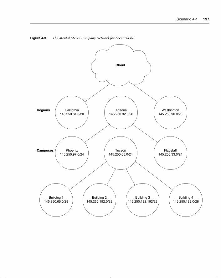
Scenario 4-1 197
Figure 4-3 The Mental Merge Company Network for Scenario 4-1
Cloud
California145.250.64.0/20
Regions
Campuses
Arizona145.250.32.0/20
Washington145.250.96.0/20
Phoenix145.250.97.0/24
Building 1145.250.65.0/28
Building 2145.250.192.0/28
Building 3145.250.192.192/28
Building 4145.250.128.0/28
Tucson145.250.65.0/24
Flagstaff145.250.33.0/24
chpt_01.book Page 197 Thursday, December 21, 2000 6:22 PM
198 Chapter 4: IP Routing Principles
Scenario 4-2Scenario 4-2 provides you with the data produced with the Cisco router IOS command show ip route. A legend defining the fields of the sample output is also provided to assist in answering the questions for Scenario 4-2.
Example 4-2 contains sample output from the show ip route command.
The following information defines the fields reported in the show ip route command:
• The first column lists the protocol that derived the route.
• The second column may list certain protocol-specific information as defined in the display header.
• The third column lists the address of the remote network. The first number in the brackets is the administrative distance of the information source; the second number is the metric for the route.
• The fourth column specifies the address of the router that can build a route to the specified remote network.
• The fifth column specifies the last time that the route was updated, in hours:minutes:seconds.
• The final column specifies the interface through which the specified network can be reached.
Example 4-2 show ip route Command Output
Codes: I - IGRP derived, R - RIP derived, H - Hello derived, O - OSPF derived C - connected, S - static, E - EGP derived, B - BGP derived * - candidate default route, IA - OSPF inter area route E1 - OSPF external type 1 route, E2 - OSPF external type 2 route
Gateway of last resort is 131.119.254.240 to network 129.140.0.0
O E2 150.150.0.0 [160/5] via 131.119.254.6, 0:01:00, Ethernet2E 192.67.131.0 [200/128] via 131.119.254.244, 0:02:22, Ethernet2O E2 192.68.132.0 [160/5] via 131.119.254.6, 0:00:59, Ethernet2O E2 130.130.0.0 [160/5] via 131.119.254.6, 0:00:59, Ethernet2E 128.128.0.0 [200/128] via 131.119.254.244, 0:02:22, Ethernet2E 129.129.0.0 [200/129] via 131.119.254.240, 0:02:22, Ethernet2E 192.65.129.0 [200/128] via 131.119.254.244, 0:02:22, Ethernet2E 131.131.0.0 [200/128] via 131.119.254.244, 0:02:22, Ethernet2E 192.75.139.0 [200/129] via 131.119.254.240, 0:02:23, Ethernet2
chpt_01.book Page 198 Thursday, December 21, 2000 6:22 PM
Scenario 4-2 199
Answer the following questions by using the output from the preceding show ip route command.
1 What routing protocol derived the route 130.130.0.0?
2 What router interface IP address is used to reach IP network 192.67.131.0?
3 When was the last time that the route 192.65.129.0 was updated?
4 Through which router interface can the IP network 128.128.0.0 be reached?
chpt_01.book Page 199 Thursday, December 21, 2000 6:22 PM
200 Chapter 4: IP Routing Principles
Scenario Answers
The answers are in bold. The answers provided in this section are not necessarily the only possible answers to the questions. The questions are designed to test your knowledge and to give practical exercise in certain key areas. This section is intended to test and exercise skills and concepts detailed in the body of this chapter.
If your answer is different, ask yourself whether it follows the tenets explained in the answers provided. Your answer is correct not if it matches the solution provided in the book, but rather if it has included the principles of design laid out in the chapter.
In this way, the testing provided in these scenarios is deeper: It examines not only your knowledge, but also your understanding and ability to apply that knowledge to problems.
If you do not get the correct answer, refer back to the text and review the subject tested. Be certain to also review your notes on the question to ensure that you understand the principles of the subject.
Scenario 4-1 Answers1 Using the addressing skills developed in Chapter 3, and in reference to Figure 4-3, state
where the routers should be placed.
The routers should be placed in each location, with the option of adding routers within each building if the network grows considerably.
2 The administrator has decided that a link-state routing protocol is the best solution for this network design. Justify his choice, explaining which characteristics of the link-state routing protocol would benefit this network.
A link-state routing protocol would be a good choice because of the large number of WAN interfaces. A distance vector routing protocol would increase congestion across these low-bandwidth links. The capability to use VLSM and to summarize these points would be an added advantage.
3 The administrator must create an implementation plan for his team. List the IP routing protocol requirements for every router that may be used as a checklist for the installation staff.
Each person implementing the routing protocol on the router would have to ensure the following:
• That the appropriate interfaces had IP addresses that were on the same subnet as the other devices on the segment.
chpt_01.book Page 200 Thursday, December 21, 2000 6:22 PM
Scenario 4-2 Answers 201
• That the routing protocol was configured correctly with the correct network addresses.
• That the routing table reflected the logical topology map of the network and that all the remote networks were present.
• If there were multiple paths available of equal cost, that the routing protocol was load sharing between the paths. This would mean all the paths were present in the routing table.
4 The links between the various sites are leased lines with a backup link using a dialup line. Should the administrator be aware of any considerations?
The leased lines to the remote sites could be configured to be the primary link; as such, no traffic would traverse the dialup links. However, routing updates would be propagated out the dialup links so that the routing table would be aware of the potential path. To prevent this (and, thus, the dialup line being raised), the path could be manually entered into the routing table. However, this would render it the preferred path. Configuring the dialup paths as floating static routes would ensure that they were used only if the primary line failed, without having to generate network traffic across the link to maintain the routing table.
Scenario 4-2 Answers1 What routing protocol derived the route 130.130.0.0?
OSPF.
2 What router interface IP address is used to reach IP network 192.67.131.0?
131.119.254.244. The fourth column of the sample output specifies the address of the router that can build a route to the specified remote network.
3 When was the last time that the route 192.65.129.0 was updated?
0:02:22. The fifth column of the sample output specifies the last time the route was updated, in hours:minutes:seconds.
4 Through which router interface can the IP network 128.128.0.0 be reached?
Ethernet2. The last column in the sample output specifies the interface through which the specified network can be reached.
chpt_01.book Page 201 Thursday, December 21, 2000 6:22 PM

This chapter covers the following topics that you will need to master to pass the CCNP/CCDP Routing exam:
• How a link-state routing protocol (in this case, OSPF) discovers, chooses, and maintains routes.
• How OSPF operates in a single nonbroadcast multiaccess (NBMA) area (such as a WAN).
• How to configure OSPF in a single area.
• How to verify the operation of and troubleshoot an OSPF network.
• The Cisco defaults in OSPF, the Cisco commands for implementing OSPF in a single area, and Cisco commands for reviewing the configuration.
chpt_01.book Page 202 Thursday, December 21, 2000 6:22 PM
C H A P T E R 5
Using OSPF in a Single Area
The topics in this chapter detail the routing protocol OSPF. This chapter assumes knowledge of the previous chapter, which dealt conceptually with routing protocols and, in particular, link-state routing protocols. This chapter covers the essence of OSPF. It introduces OSPF by considering the protocol in its simplest form, within a single area. Both the basic operations of the protocol and its configuration are explained in this chapter. The following chapter builds on this understanding and explains how OSPF works within a large multiarea network. Each of these chapters is broken into two sections. The first part of the chapter deals theoretically with how the protocol works. The second part of the chapter covers how to implement and manage an OSPF network.
The topics in this chapter directly reflect questions on the exam. OSPF is the industry-standard interior routing protocol designed for use in large networks. Therefore, it is an obligatory subject in an exam on IP routing protocols. The BSCN course devotes 13 percent of its material to using OSPF in a single area, and you can expect approximately seven questions on the exam to be directly related to this subject. The following chapter assumes your comprehension of the subjects covered within this chapter.
How to Best Use This ChapterBy taking the following steps, you can make better use of your study time:
• Keep your notes and the answers for all your work with this book in one place, for easy reference.
• When you take a quiz, write down your answers. Studies show that retention significantly increases by writing down facts and concepts, even if you never look at the information again.
• Use the diagram in Figure 5-1 to guide you to the next step.
chpt_01.book Page 203 Thursday, December 21, 2000 6:22 PM
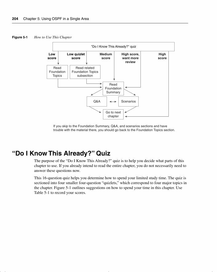
204 Chapter 5: Using OSPF in a Single Area
Figure 5-1 How to Use This Chapter
“Do I Know This Already?” QuizThe purpose of the “Do I Know This Already?” quiz is to help you decide what parts of this chapter to use. If you already intend to read the entire chapter, you do not necessarily need to answer these questions now.
This 16-question quiz helps you determine how to spend your limited study time. The quiz is sectioned into four smaller four-question “quizlets,” which correspond to four major topics in the chapter. Figure 5-1 outlines suggestions on how to spend your time in this chapter. Use Table 5-1 to record your scores.
Lowscore
Low quizletscore
Mediumscore
High score,want more
review
Highscore
"Do I Know This Already?" quiz
ReadFoundation
Topics
Read relatedFoundation Topics
subsection
ReadFoundationSummary
Q&A Scenarios
Go to nextchapter
If you skip to the Foundation Summary, Q&A, and scenarios sections and havetrouble with the material there, you should go back to the Foundation Topics section.
chpt_01.book Page 204 Thursday, December 21, 2000 6:22 PM
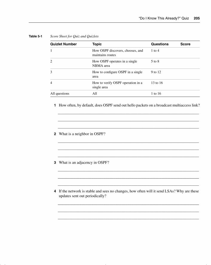
“Do I Know This Already?” Quiz 205
1 How often, by default, does OSPF send out hello packets on a broadcast multiaccess link?
_______________________________________________________________________
_______________________________________________________________________
_______________________________________________________________________
2 What is a neighbor in OSPF?
_______________________________________________________________________
_______________________________________________________________________
_______________________________________________________________________
3 What is an adjacency in OSPF?
_______________________________________________________________________
_______________________________________________________________________
_______________________________________________________________________
4 If the network is stable and sees no changes, how often will it send LSAs? Why are these updates sent out periodically?
_______________________________________________________________________
_______________________________________________________________________
_______________________________________________________________________
Table 5-1 Score Sheet for Quiz and Quizlets
Quizlet Number Topic Questions Score
1 How OSPF discovers, chooses, and maintains routes
1 to 4
2 How OSPF operates in a single NBMA area
5 to 8
3 How to configure OSPF in a single area
9 to 12
4 How to verify OSPF operation in a single area
13 to 16
All questions All 1 to 16
chpt_01.book Page 205 Thursday, December 21, 2000 6:22 PM
206 Chapter 5: Using OSPF in a Single Area
5 If a router has an OSPF priority set to 0, what does this indicate?
______________________________________________________________________
______________________________________________________________________
______________________________________________________________________
6 What does NBMA stand for?
______________________________________________________________________
______________________________________________________________________
______________________________________________________________________
7 RFC 2328 describes the operation of OSPF in two modes across an NBMA cloud. What are they?
______________________________________________________________________
______________________________________________________________________
______________________________________________________________________
8 The Cisco solution point-to-point mode does not require the configuration of DR and BDR. Explain briefly why.
______________________________________________________________________
______________________________________________________________________
______________________________________________________________________
9 The address 192.100.56.10 has been allocated to an interface on the router. This interface alone is to be included in the OSPF process. State the command that would start the process on this interface.
______________________________________________________________________
______________________________________________________________________
______________________________________________________________________
10 What command would identify the designated router for your LAN?
______________________________________________________________________
______________________________________________________________________
______________________________________________________________________
chpt_01.book Page 206 Thursday, December 21, 2000 6:22 PM
“Do I Know This Already?” Quiz 207
11 The metric used by OSPF is cost. How would you change the default setting on an interface?
_______________________________________________________________________
_______________________________________________________________________
_______________________________________________________________________
12 If the command ip ospf network non-broadcast is used, what additional statement is necessary?
_______________________________________________________________________
_______________________________________________________________________
_______________________________________________________________________
13 What command shows which router on a LAN is the BDR?
_______________________________________________________________________
_______________________________________________________________________
_______________________________________________________________________
14 Explain briefly what show ip ospf database will reveal.
_______________________________________________________________________
_______________________________________________________________________
_______________________________________________________________________
15 What command is used to show the state of adjacencies?
_______________________________________________________________________
_______________________________________________________________________
_______________________________________________________________________
16 It is possible to have more than one OSPF process on a router. Which command would achieve this?
_______________________________________________________________________
_______________________________________________________________________
_______________________________________________________________________
chpt_01.book Page 207 Thursday, December 21, 2000 6:22 PM
208 Chapter 5: Using OSPF in a Single Area
The answers to this quiz are found in Appendix A, “Answers to Quiz Questions.” The suggested choices for your next step are as follows:
• 2 or less on any quizlet—Review the appropriate sections of the “Foundation Topics” portion of this chapter, based on Table 5-1. Then move on to the “Foundation Summary” section, the “Q&A” section, and the “Scenarios” at the end of the chapter.
• 8 or less overall score—Read the entire chapter. This includes the “Foundation Topics” and “Foundation Summary” sections, the “Q&A” section, and the “Scenarios” at the end of the chapter.
• 9 to 12 overall score—Begin with the “Foundation Summary” section, and then go to the “Q&A” section and the “Scenarios” at the end of the chapter. If you have trouble with these exercises, read the appropriate sections in “Foundation Topics.”
• 13 or more overall score—If you want more review on these topics, skip to the “Foundation Summary” section, and then go to the “Q&A” section and the “Scenarios” at the end of the chapter. Otherwise, move to the next chapter.
chpt_01.book Page 208 Thursday, December 21, 2000 6:22 PM
Introduction: What Is OSPF? 209
Foundation Topics
Introduction: What Is OSPF?OSPF stands for Open Shortest Path First, an open standard link-state routing protocol. This routing protocol was built by a committee, which is why it is an open standard. The word open means that anyone can read the rules or standard and write an application. The routing protocol as such belongs to no one, but to everyone.
OSPF’s purpose as a routing protocol is to convey routing information to every router within the organizational network. The technology that has been selected is link-state technology, which was designed to be very efficient in the way it propagates updates, allowing the network to grow.
The following case study describes a small company that has been bought, along with other companies, by a large conglomerate. The need to change the routing protocol to inform the newly expanded network is urgent.
Case StudyThe company Jackanory.com has been writing very successful multimedia applications for the last five years. The company is based in Los Angeles, although its clientele are located throughout the United States. Jackanory.com specializes in educational software tailored to a large company’s specific training needs—for example, teaching the retail sales teams of a multinational car manufacturer how to sell cars. Internally, the company needs high-bandwidth pipes that cannot be clogged with network overhead. Until recently, there was little external communication, except for the occasional connection to a customer for maintenance.
However, the company was recently bought by a British company that merged them with a small company emerging in San Francisco. Consequently, the company has grown enormously in size and looks to be growing fast and furiously in the exciting new world of digital imaging.
RIPv1 is no longer adequate. Although it works well for the range of vendors within the network, it cannot cope with the WAN or the new size of the network. It has been decreed that OSPF is the routing protocol of choice.
The network administrators need to understand the mechanics of the routing protocol to design and implement it into the network. They also need to know how to interrogate the network to monitor, troubleshoot, and fix the network.
The first stage of implementation is to install OSPF on the original network in Los Angeles. The next stage will introduce the other locations after Los Angeles is installed and stable. These locations will be configured as separate areas, which is described in the following chapter.
chpt_01.book Page 209 Thursday, December 21, 2000 6:22 PM
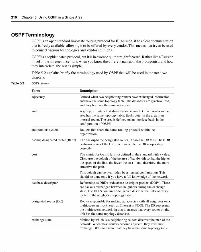
210 Chapter 5: Using OSPF in a Single Area
OSPF TerminologyOSPF is an open standard link-state routing protocol for IP. As such, it has clear documentation that is freely available, allowing it to be offered by every vendor. This means that it can be used to connect various technologies and vendor solutions.
OSPF is a sophisticated protocol, but it is in essence quite straightforward. Rather like a Russian novel of the nineteenth century, when you know the different names of the protagonists and how they interrelate, the rest is simple.
Table 5-2 explains briefly the terminology used by OSPF that will be used in the next two chapters.
Table 5-2 OSPF Terms
Term Description
adjacency Formed when two neighboring routers have exchanged information and have the same topology table. The databases are synchronized, and they both see the same networks.
area A group of routers that share the same area ID. Each router in the area has the same topology table. Each router in the area is an internal router. The area is defined on an interface basis in the configuration of OSPF.
autonomous system Routers that share the same routing protocol within the organization.
backup designated router (BDR) The backup to the designated router, in case the DR fails. The BDR performs none of the DR functions while the DR is operating correctly.
cost The metric for OSPF. It is not defined in the standard with a value. Cisco use the default of the inverse of bandwidth so that the higher the speed of the link, the lower the cost—and, therefore, the more attractive the path.
This default can be overridden by a manual configuration. This should be done only if you have a full knowledge of the network.
database descriptor Referred to as DBDs or database descriptor packets (DDPs). These are packets exchanged between neighbors during the exchange state. The DDPs contain LSAs, which describe the links of every router in the neighbor’s topology table.
designated router (DR) Router responsible for making adjacencies with all neighbors on a multiaccess network, such as Ethernet or FDDI. The DR represents the multiaccess network, in that it ensures that every router on the link has the same topology database.
exchange state Method by which two neighboring routers discover the map of the network. When these routers become adjacent, they must first exchange DDPs to ensure that they have the same topology table.
chpt_01.book Page 210 Thursday, December 21, 2000 6:22 PM
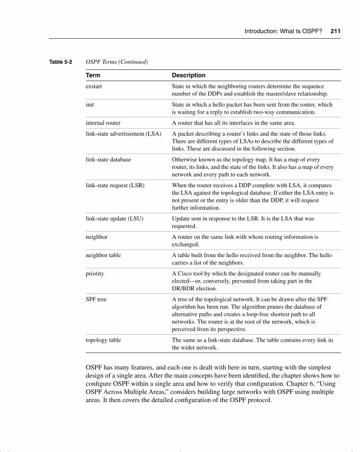
Introduction: What Is OSPF? 211
OSPF has many features, and each one is dealt with here in turn, starting with the simplest design of a single area. After the main concepts have been identified, the chapter shows how to configure OSPF within a single area and how to verify that configuration. Chapter 6, “Using OSPF Across Multiple Areas,” considers building large networks with OSPF using multiple areas. It then covers the detailed configuration of the OSPF protocol.
exstart State in which the neighboring routers determine the sequence number of the DDPs and establish the master/slave relationship.
init State in which a hello packet has been sent from the router, which is waiting for a reply to establish two-way communication.
internal router A router that has all its interfaces in the same area.
link-state advertisement (LSA) A packet describing a router’s links and the state of those links. There are different types of LSAs to describe the different types of links. These are discussed in the following section.
link-state database Otherwise known as the topology map. It has a map of every router, its links, and the state of the links. It also has a map of every network and every path to each network.
link-state request (LSR) When the router receives a DDP complete with LSA, it compares the LSA against the topological database. If either the LSA entry is not present or the entry is older than the DDP, it will request further information.
link-state update (LSU) Update sent in response to the LSR. It is the LSA that was requested.
neighbor A router on the same link with whom routing information is exchanged.
neighbor table A table built from the hello received from the neighbor. The hello carries a list of the neighbors.
priority A Cisco tool by which the designated router can be manually elected—or, conversely, prevented from taking part in the DR/BDR election.
SPF tree A tree of the topological network. It can be drawn after the SPF algorithm has been run. The algorithm prunes the database of alternative paths and creates a loop-free shortest path to all networks. The router is at the root of the network, which is perceived from its perspective.
topology table The same as a link-state database. The table contains every link in the wider network.
Table 5-2 OSPF Terms (Continued)
Term Description
chpt_01.book Page 211 Thursday, December 21, 2000 6:22 PM
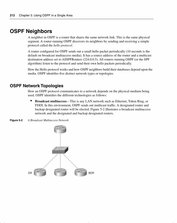
212 Chapter 5: Using OSPF in a Single Area
OSPF NeighborsA neighbor in OSPF is a router that shares the same network link. This is the same physical segment. A router running OSPF discovers its neighbors by sending and receiving a simple protocol called the hello protocol.
A router configured for OSPF sends out a small hello packet periodically (10 seconds is the default on broadcast multiaccess media). It has a source address of the router and a multicast destination address set to AllSPFRouters (224.0.0.5). All routers running OSPF (or the SPF algorithm) listen to the protocol and send their own hello packets periodically.
How the Hello protocol works and how OSPF neighbors build their databases depend upon the media. OSPF identifies five distinct network types or topologies.
OSPF Network TopologiesHow an OSPF protocol communicates to a network depends on the physical medium being used. OSPF identifies the different technologies as follows:
• Broadcast multiaccess—This is any LAN network such as Ethernet, Token Ring, or FDDI. In this environment, OSPF sends out multicast traffic. A designated router and backup designated router will be elected. Figure 5-2 illustrates a broadcast multiaccess network and the designated and backup designated routers.
Figure 5-2 A Broadcast Multiaccess Network
DR BDR
chpt_01.book Page 212 Thursday, December 21, 2000 6:22 PM
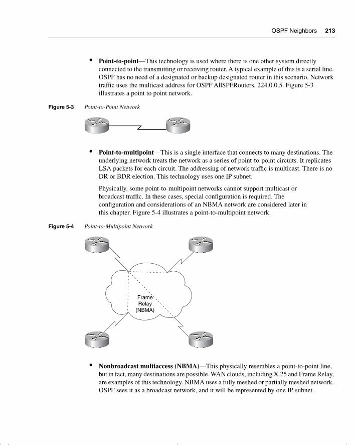
OSPF Neighbors 213
• Point-to-point—This technology is used where there is one other system directly connected to the transmitting or receiving router. A typical example of this is a serial line. OSPF has no need of a designated or backup designated router in this scenario. Network traffic uses the multicast address for OSPF AllSPFRouters, 224.0.0.5. Figure 5-3 illustrates a point to point network.
Figure 5-3 Point-to-Point Network
• Point-to-multipoint—This is a single interface that connects to many destinations. The underlying network treats the network as a series of point-to-point circuits. It replicates LSA packets for each circuit. The addressing of network traffic is multicast. There is no DR or BDR election. This technology uses one IP subnet.
Physically, some point-to-multipoint networks cannot support multicast or broadcast traffic. In these cases, special configuration is required. The configuration and considerations of an NBMA network are considered later in this chapter. Figure 5-4 illustrates a point-to-multipoint network.
Figure 5-4 Point-to-Multipoint Network
• Nonbroadcast multiaccess (NBMA)—This physically resembles a point-to-point line, but in fact, many destinations are possible. WAN clouds, including X.25 and Frame Relay, are examples of this technology. NBMA uses a fully meshed or partially meshed network. OSPF sees it as a broadcast network, and it will be represented by one IP subnet.
FrameRelay
(NBMA)
chpt_01.book Page 213 Thursday, December 21, 2000 6:22 PM
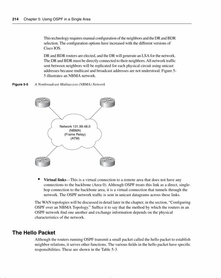
214 Chapter 5: Using OSPF in a Single Area
This technology requires manual configuration of the neighbors and the DR and BDR selection. The configuration options have increased with the different versions of Cisco IOS.
DR and BDR routers are elected, and the DR will generate an LSA for the network. The DR and BDR must be directly connected to their neighbors. All network traffic sent between neighbors will be replicated for each physical circuit using unicast addresses because multicast and broadcast addresses are not understood. Figure 5-5 illustrates an NBMA network.
Figure 5-5 A Nonbroadcast Multiaccess (NBMA) Network
• Virtual links—This is a virtual connection to a remote area that does not have any connections to the backbone (Area 0). Although OSPF treats this link as a direct, single-hop connection to the backbone area, it is a virtual connection that tunnels through the network. The OSPF network traffic is sent in unicast datagrams across these links.
The WAN topologies will be discussed in detail later in the chapter, in the section, “Configuring OSPF over an NBMA Topology.” Suffice it to say that the method by which the routers in an OSPF network find one another and exchange information depends on the physical characteristics of the network.
The Hello PacketAlthough the routers running OSPF transmit a small packet called the hello packet to establish neighbor relations, it serves other functions. The various fields in the hello packet have specific responsibilities. These are shown in the Table 5-3.
Network 131.99.48.0(NBMA)
(Frame Relay)(ATM)
chpt_01.book Page 214 Thursday, December 21, 2000 6:22 PM
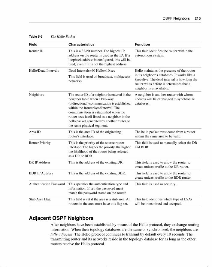
OSPF Neighbors 215
Adjacent OSPF NeighborsAfter neighbors have been established by means of the Hello protocol, they exchange routing information. When their topology databases are the same or synchronized, the neighbors are fully adjacent. The Hello protocol continues to transmit by default every 10 seconds. The transmitting router and its networks reside in the topology database for as long as the other routers receive the Hello protocol.
Table 5-3 The Hello Packet
Field Characteristics Function
Router ID This is a 32-bit number. The highest IP address on the router is used as the ID. If a loopback address is configured, this will be used, even if it is not the highest address.
This field identifies the router within the autonomous system.
Hello/Dead Intervals Dead Intervals=40 Hello=10 sec
This field is used on broadcast, multiaccess networks.
Hello maintains the presence of the router in its neighbor’s databases. It works like a keepalive. The dead interval is how long the router waits before it determines that a neighbor is unavailable.
Neighbors The router ID of a neighbor is entered in the neighbor table when a two-way (bidirectional) communication is established within the RouterDeadInterval. The communication is established when the router sees itself listed as a neighbor in the hello packet generated by another router on the same physical segment.
A neighbor is another router with whom updates will be exchanged to synchronize databases.
Area ID This is the area ID of the originating router’s interface.
The hello packet must come from a router within the same area to be valid.
Router Priority This is the priority of the source router interface. The higher the priority, the higher the likelihood of the router being selected as a DR or BDR.
This field is used to manually select the DR and BDR.
DR IP Address This is the address of the existing DR. This field is used to allow the router to create unicast traffic to the DR router.
BDR IP Address This is the address of the existing BDR. This field is used to allow the router to create unicast traffic to the BDR router.
Authentication Password This specifies the authentication type and information. If set, the password must match the password stated on the router.
This field is used as security.
Stub Area Flag This field is set if the area is a stub area. All routers in the area must have this flag set.
This field identifies which type of LSAs will be transmitted and accepted.
chpt_01.book Page 215 Thursday, December 21, 2000 6:22 PM
216 Chapter 5: Using OSPF in a Single Area
Advantages of Having NeighborsThere are obvious advantages to creating neighbor relationships. These advantages include the following:
• There is another mechanism for determining that a router has gone down (obvious because its neighbor no longer sends Hello packets).
• Streamlined communication results because after the topological databases are synchronized, incremental updates will be sent to the neighbors as soon as a change is perceived, as well as every 30 minutes.
• Adjacencies created between neighbors control the distribution of the routing protocol packets.
The use of adjacencies and a neighbor relationship result in a much faster convergence of the network than can be achieved by RIPv1. This is because RIPv1 must wait for incremental updates and holddown timers to expire on each router before the update is sent out. Convergence on a RIPv1 network can take many minutes, and the real problem is the confusion created by the different routing tables held on different routers during this time. This problem can result in routing loops and black holes in the network.
The Designated RouterThe designated router is a router on broadcast multiaccess media that is responsible for maintaining the topology table for the segment.
If routers are connected to a broadcast segment, one router on the segment is assigned the duty of maintaining adjacencies with all the routers on the segment. This router is known as the designated router and is elected by the use of the Hello protocol. The hello packet carries the information that determines the DR and the BDR. The election is determined by either the highest IP address or this command:
ip ospf priority number
All other routers need only peer with the designated router, which informs them of any changes on the segment.
Backup Designated RoutersThe previous paragraph is only a half truth because there has been a lot of effort put into ensuring that the network does not fail. It is a little nerve-racking for the network administrator to have the responsibility of the segment fall to one router. This poses the frightening situation of a single point of failure, a term that raises the blood pressure of any of those in charge of the network. Redundancy has been built into the network with the backup designated router. Just like an understudy, the backup designated router knows all the words—in this case, the links for the segment. All routers actually have an adjacency not only with the designated router, but
chpt_01.book Page 216 Thursday, December 21, 2000 6:22 PM
OSPF Neighbors 217
also with the backup designated router, which in turn has an adjacency with the designated router. If the designated router fails, the backup designated router immediately becomes the designated router.
Why Have Designated Routers?Designated routers are created on multiaccess links because if there are many routers on the same segment, the intermesh of neighbor relationships becomes complex. On an FDDI ring, which forms the campus or building backbone, each router must form an adjacency with every other router on the segment. Although the Hello protocol is not networking-intensive, maintaining the relationships require additional CPU cycles. Also, there is a sharp increase in the number of LSAs generated.
Electing the Designated and Backup Designated RoutersThe network administrator can manually elect the designated and backup designated routers, or they can be dynamically selected using the Hello protocol.
Dynamic ElectionWhen selected dynamically, the designated router is elected arbitrarily. The selection is made on the basis of the highest router ID or IP address. It is wise to be aware that the highest IP address is the numerically highest number, not the class ranking of the addresses. Therefore, a remote, small router with a Class C address may end up as a designated router. This may not be the optimal choice.
If you are manually determining which routers are to be the designated and backup designated routers, it is easier to design your network to the optimum.
After the designated and backup designated routers have been elected, all routers on the broadcast medium will communicate directly with the designated routers. They will use the multicast address to all designated routers. The backup router will listen but will not respond; remember, it is the understudy waiting in the wings. The designated router will send out multicast messages if it receives any information pertinent to the connected routers for which it is responsible.
Manual Configuration of the Designated RouterTo manually determine which router will be the designated router, it is necessary to set the priority of the router. A router interface can have a priority of 0 to 255. The value of 0 means that the router cannot be a designated router or backup designated router; otherwise, the higher the priority, the more favorable the chances are of winning the election.
chpt_01.book Page 217 Thursday, December 21, 2000 6:22 PM
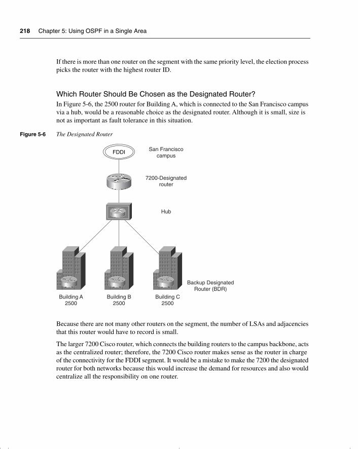
218 Chapter 5: Using OSPF in a Single Area
If there is more than one router on the segment with the same priority level, the election process picks the router with the highest router ID.
Which Router Should Be Chosen as the Designated Router?In Figure 5-6, the 2500 router for Building A, which is connected to the San Francisco campus via a hub, would be a reasonable choice as the designated router. Although it is small, size is not as important as fault tolerance in this situation.
Figure 5-6 The Designated Router
Because there are not many other routers on the segment, the number of LSAs and adjacencies that this router would have to record is small.
The larger 7200 Cisco router, which connects the building routers to the campus backbone, acts as the centralized router; therefore, the 7200 Cisco router makes sense as the router in charge of the connectivity for the FDDI segment. It would be a mistake to make the 7200 the designated router for both networks because this would increase the demand for resources and also would centralize all the responsibility on one router.
FDDI San Franciscocampus
7200-Designatedrouter
Hub
Building A2500
Building B2500
Building C2500
Backup DesignatedRouter (BDR)
chpt_01.book Page 218 Thursday, December 21, 2000 6:22 PM
OSPF Neighbors 219
The Election of the Designated RouterThe following is the process used to elect the designated and backup designated routers:
• All the neighbors who have a priority greater than 0 are listed.
• The neighbor with the highest priority is elected as the BDR.
• If there is no DR, the BDR is promoted as DR.
• From the remaining routers, the router with the highest priority is elected as the BDR.
• If there is a tie, the highest router IDs are used.
How OSPF Builds Its Routing TableAfter a neighbor is discovered in OSPF, an adjacency is formed. It is important to understand how the neighbor adjacency is formed and, in this context, to understand the other messages that the routers receive.
Routing tables are built in two different ways. The next sections examine these in more detail.
A Router Joins the NetworkThe first way to build a routing table is for a new router to be added to the network and then for it to build a routing table by listening to the established routers with complete routing tables. Remember that every router within an area will have the same database and will know of every network within the area. The routing table built from this database is unique to the router because the decisions depend on the individual router’s position within the area, relative to the remote destination network.
A Change in the NetworkA change in the network topology also necessitates information to be propagated through the network. For example, the rest of the network notices that a new router has joined their ranks.
A particular router that notices a change floods the area with the update so that all routers can alter their routing tables to reflect the most current and accurate information.
Different techniques are used for these different routing table requirements. Essentially, the difference between the two techniques is simple:
• If a new router connects to a network, it will find a neighbor using the Hello protocol and will exchange routing information.
• If a change occurs in an existing network, the router that sees the change will flood the area with the new routing information.
chpt_01.book Page 219 Thursday, December 21, 2000 6:22 PM
220 Chapter 5: Using OSPF in a Single Area
NOTE Both of these events must occur as stated because, although the new router must learn the network topology, its addition is a change to the rest of the network.
These two requirements for updating the routing table use different technologies and OSPF protocols. These technologies and protocols are often confused, so it is worth a moment to distinguish them. Understanding the distinction makes the OSPF operation much clearer.
Building the Routing Table on a New OSPF RouterFive packets are used to build the routing table for the first time:
• Hello protocol—Is used to find neighbors and to determine the designated and backup designated router. The continued propagation of the Hello protocol maintains the transmitting router in the topology database of those that hear the message.
• Database descriptor—Is used to send summary information to neighbors to synchronize topology databases.
• Link-state request—Works as a request for more detailed information, which is sent when the router receives a database descriptor that contains new information.
• Link-state update—Works as the link-state advertisement (LSA) packet issued in response to the request for database information in the link-state request packet. The different types of LSA are described in Chapter 6, in the section “The Link-State Advertisements.”
• Link-state acknowledgement—Acknowledges the link-state update.
Consider the case of when a router joins the OSPF network for the first time. In Figure 5-7, the 2500 router in Building A at the San Francisco campus has just been connected.
The next sections detail what happens when a router joins a network.
Finding Neighbors with the Exchange ProcessWhen it is connected to the network and has been configured to run OSPF, the new router must learn the network from the systems that are up and running. The method shown here, however, is the same as for a stable network.
This process is shown in the stages that the systems go through while exchanging information. It is possible to see what stage an interface running OSPF is in with the command show ip ospf neighbor as well as the command debug ip ospf adjacency. Care should be taken with the debug command because it can be CPU-intensive.
chpt_01.book Page 220 Thursday, December 21, 2000 6:22 PM
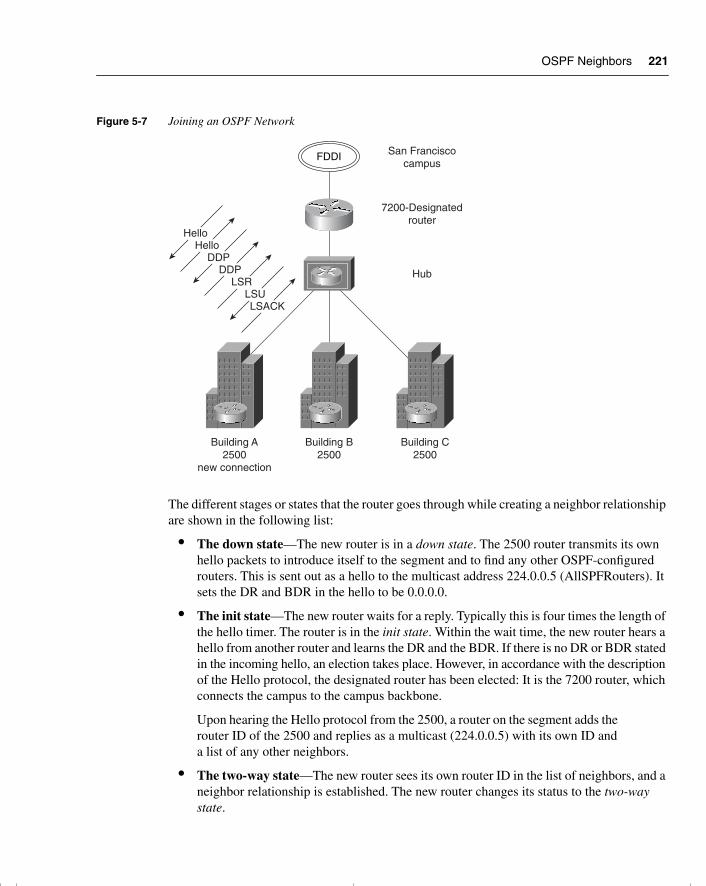
OSPF Neighbors 221
Figure 5-7 Joining an OSPF Network
The different stages or states that the router goes through while creating a neighbor relationship are shown in the following list:
• The down state—The new router is in a down state. The 2500 router transmits its own hello packets to introduce itself to the segment and to find any other OSPF-configured routers. This is sent out as a hello to the multicast address 224.0.0.5 (AllSPFRouters). It sets the DR and BDR in the hello to be 0.0.0.0.
• The init state—The new router waits for a reply. Typically this is four times the length of the hello timer. The router is in the init state. Within the wait time, the new router hears a hello from another router and learns the DR and the BDR. If there is no DR or BDR stated in the incoming hello, an election takes place. However, in accordance with the description of the Hello protocol, the designated router has been elected: It is the 7200 router, which connects the campus to the campus backbone.
Upon hearing the Hello protocol from the 2500, a router on the segment adds the router ID of the 2500 and replies as a multicast (224.0.0.5) with its own ID and a list of any other neighbors.
• The two-way state—The new router sees its own router ID in the list of neighbors, and a neighbor relationship is established. The new router changes its status to the two-way state.
FDDI San Franciscocampus
7200-Designatedrouter
Hub
Building A2500
new connection
Building B2500
Building C2500
HelloHello
DDPDDP
LSRLSULSACK
chpt_01.book Page 221 Thursday, December 21, 2000 6:22 PM
222 Chapter 5: Using OSPF in a Single Area
Discovering RoutesThe 2500 and the designated router have now established a neighbor relationship and need to ensure that the 2500 has all the relevant information about the network. The 7200 must update and synchronize the topology database of the 2500. This is achieved by using the exchange protocol with the database description packets.
The different stages or states that the router goes through while exchanging routing information with a neighbor are shown in the following list:
• The exstart state—One of the routers will take seniority, becoming the master router. This is the exstart state. The two neighbors determine a master/slave relationship based on highest IP interface address. This designation is not significant; it just determines who starts the communication.
• The exchange state—Both routers will send out database description packets, changing the state to the exchange state.
In this example, the 2500 has no knowledge and can inform the 7200 only of the networks or links to which it is directly connected. The 7200 sends out a series of database description packets containing the networks held in the topology database. These networks are referred to as links.
Most of these have been received from other routers (via link-state advertisements). The source of the link information is referred to by the router ID.
Each link will have an interface ID for the outgoing interface, a link ID, and a metric to state the value of the path. The database description packet will not contain all the necessary information—just a summary (enough for the receiving router to determine whether more information is required or whether it already contains that entry in its database).
When the router has received the DDPs from the neighboring router, it compares the received network information with that in its topology table. In the case of a new router, such as the 2500, all the DDPs are new. The different stages or states that the router goes through gathering routing information form a neighbor are shown in the following list:
• The loading state—If the receiving router, the 2500, requires more information, it will request that particular link in more detail using the link-state request packet (LSR).
The LSR will prompt the master router to send the link-state update packet (LSU). Figure 5-8 illustrates this as well. This is the same as a link-state advertisement (LSA) used to flood the network with routing information. While the 2500 is awaiting the LSUs from its neighbor, it is in the loading state.
• The full state—When these LSRs are received and the databases are updated and synchronized, the neighbors are fully adjacent.
This exchange is illustrated in the Figure 5-8.
chpt_01.book Page 222 Thursday, December 21, 2000 6:22 PM
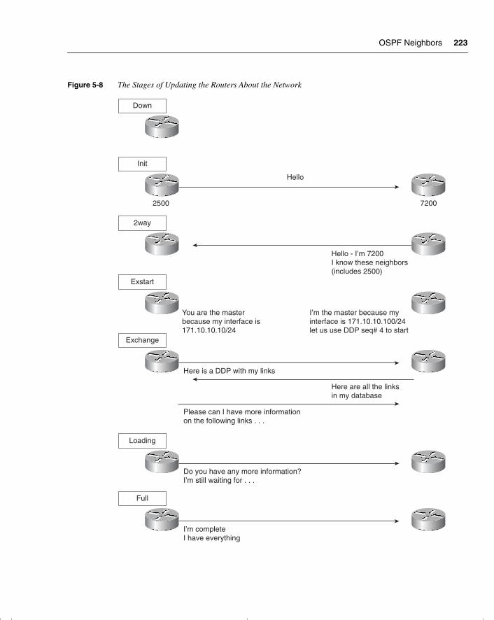
OSPF Neighbors 223
Figure 5-8 The Stages of Updating the Routers About the Network
Init
72002500
Hello
2way
Hello - I’m 7200I know these neighbors(includes 2500)
Exchange
Here are all the linksin my database
Here is a DDP with my links
Loading
Do you have any more information?I’m still waiting for . . .
Please can I have more informationon the following links . . .
Down
Exstart
You are the masterbecause my interface is171.10.10.10/24
Full
I’m completeI have everything
I’m the master because myinterface is 171.10.10.100/24let us use DDP seq# 4 to start
chpt_01.book Page 223 Thursday, December 21, 2000 6:22 PM
224 Chapter 5: Using OSPF in a Single Area
The process described in the previous section takes you through the process of learning about the network. The first stage is to learn the neighbors at the other end of the link that directly attaches. This information is stored in the neighbor table.
The second stage is to learn from the neighbors the links throughout the network. This information described previously updates the topology database, sometimes referred to as the link-state database.
The Topology DatabaseThe topology database is the router’s view of the network within the area. It includes every OSPF router within the area and all the connected networks. This database is indeed a routing table, but a routing table for which no path decisions have been made; it is at present a topology database.
The topology database is updated by the LSAs. Each router within the area has exactly the same topology database. All routers must have the same vision of the network; otherwise, confusion, routing loops, and loss of connectivity will result.
The synchronization of the topology maps is ensured by the intricate use of sequence numbers in the LSA headers.
How the Topology Table Updates the Routing TableFrom the topology map, a routing database is constructed. This database will be unique to each router, which creates a routing database by running the shortest path first (SPF) algorithm called the Dijkstra algorithm. Each router uses this algorithm to determine the best path to each network and creates an SPF tree on which it places itself at the top or root. If there are equal metrics for a remote network, OSPF includes all the paths and load balances the routed data traffic among them.
Occasionally a link may flap, go up and down. This is more usual on a serial line. If this happens, it could cause many LSAs to be generated in updating the network. To prevent this from happening, OSPF introduced timers. These timers forced OSPF to wait before recalculating SPF. These timers are configurable.
NOTE Although RFC 2328 does not state the number of multiple, equal-cost paths that can be used at the same time, Cisco has defined a maximum of six paths that can be used simultaneously for load balancing.
chpt_01.book Page 224 Thursday, December 21, 2000 6:22 PM
OSPF Neighbors 225
A Change in the Network, Maintaining the Topological Database and the Routing TableNow turn back to the 2500 router in Building A of the San Francisco campus in Figure 5-6. The router is now happily a member of the OSPF network. Now follow the process of hearing an update to the network in the form of an LSA.
As soon as a router realizes that there has been a change in the network topology, the router is responsible for informing the rest of the routers in the area. Typically, it will identify a change in the state of one of its links for one of the following reasons:
• The router loses the physical or data link layer connectivity on a connected network. It will propagate an LSU and send it to the DR on a multiaccess network or the adjacent router in a point-to-point network. From there, it is flooded to the network.
• The router fails to hear either an OSPF Hello protocol or a data link Hello protocol. It will propagate an LSU and send it to the DR on a multiaccess network or the adjacent router in a point-to-point network. From there, it is flooded to the network.
• It receives an LSA update from an adjacent neighbor, informing it of the change in the network topology. The LSU is acknowledged and flooded out the other OSPF interfaces.
In any of these instances, the router will generate an LSA and flood it to all its neighbors.
This discussion now turns to the process initiated when a router receives such an update. For this purpose, return to the 2500 connected to its designated router, the 7200.
Learning a New RouteWhen the 2500 receives a network LSA update from the designated router, it goes through the following logical steps:
1 The router takes the first entry from the update—the first network with information about the state of its link.
2 The router verifies the type of LSA is one that can be accepted by this router.
3 Having ascertained that it is a valid LSA that it can receive, the router issues a lookup to its topological database.
4 If the LSA entry is not in the topological database, it is flooded immediately out all the OSPF interfaces, except for the receiving interface.
5 If the LSA entry is in the topological database, further questions are required.
6 The router determines whether the new LSA has a more recent (higher) sequence number?
7 If the sequence numbers are the same, the router calculates the checksum for the LSAs and uses the LSA with the higher checksum.
chpt_01.book Page 225 Thursday, December 21, 2000 6:22 PM
226 Chapter 5: Using OSPF in a Single Area
8 If the checksum numbers are the same, the router checks the MaxAge field to ascertain which is the more recent update.
9 Having found that the latest LSU is the one that was received, the router determines whether it has arrived outside the wait period, before another computation is allowed (minsLSarrival).
10 If the new LSA entry passes these tests, it is flooded out all the OSPF interfaces, except for the receiving interface.
11 The current copy replaces the old LSA entry. If there was no entry, the current copy is just placed in the database.
12 The received LSA is acknowledged.
13 If the LSA entry was in the database, but the LSA that has just been received has an older sequence number, the process will ask whether the information in the database is the same.
14 If the information is the same and the new LSA has an older sequence number, the process just discards the packet. It may be old news, but there is no inconsistency in the database.
15 If the information is different and the newly received LSA has an older sequence number, however, the receiving router discards the LSA update. It issues its own LSA out the receiving interface to the source address of the out-of-date LSA. The logic is that the sending router either has bad or old information and must be updated because its topological database is obviously not synchronized with the rest of the area.
This ensures that any packets that get out of sequence will be verified before action is taken. It also attempts to rectify a problem that it sees—that of multiple routers offering different paths because their topological databases are completely confused.
16 After the initial flood, things calm down, and updates are sent only when there are changes in the area or when the 30-minute timer goes off. This timer ensures that the databases stay synchronized.
This shows some of the internal complexity of OSPF. As you can see, the internals are extremely detailed. Therefore, the design of any OSPF network should be very carefully thought out. The configuration of the routing protocol, on the other hand, is incredibly straightforward.
Figure 5-9 shows a logical flowchart of how the OSPF topological database is updated.
As you have seen, different types of LSA are propagated through the network. Figure 5-10 illustrates graphically the flooding of an LSA through the network.
chpt_01.book Page 226 Thursday, December 21, 2000 6:22 PM
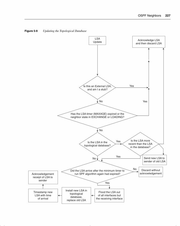
OSPF Neighbors 227
Figure 5-9 Updating the Topological Database
No
No
No
Yes
LSAUpdate
No
Yes
Yes
Yes
Yes
Acknowledge LSAand then discard LSA
Has the LSA timer (MAXAGE) expired or theneighbor state in EXCHANGE or LOADING?
Is the LSA in thetopological database?
Is the LSA morerecent than the LSA
in the database?
Discard withoutacknowledgement
Send new LSA to sender of old LSA
Is this an External LSA,and am I a stub?
Did the LSA arrive after the minimum timer torun SPF algorithm again had expired?
Flood the LSA outof all interfaces but
the receiving interface
Install new LSA intopologicaldatabase,
replace old LSA
Timestamp newLSA with time
of arrival
Acknowledgementreceipt of LSA to
sender
chpt_01.book Page 227 Thursday, December 21, 2000 6:22 PM
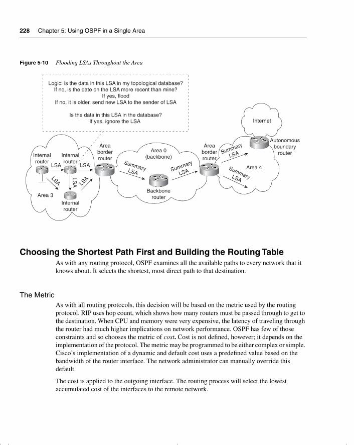
228 Chapter 5: Using OSPF in a Single Area
Figure 5-10 Flooding LSAs Throughout the Area
Choosing the Shortest Path First and Building the Routing TableAs with any routing protocol, OSPF examines all the available paths to every network that it knows about. It selects the shortest, most direct path to that destination.
The MetricAs with all routing protocols, this decision will be based on the metric used by the routing protocol. RIP uses hop count, which shows how many routers must be passed through to get to the destination. When CPU and memory were very expensive, the latency of traveling through the router had much higher implications on network performance. OSPF has few of those constraints and so chooses the metric of cost. Cost is not defined, however; it depends on the implementation of the protocol. The metric may be programmed to be either complex or simple. Cisco’s implementation of a dynamic and default cost uses a predefined value based on the bandwidth of the router interface. The network administrator can manually override this default.
The cost is applied to the outgoing interface. The routing process will select the lowest accumulated cost of the interfaces to the remote network.
Logic: is the data in this LSA in my topological database?If no, is the date on the LSA more recent than mine?
If yes, floodIf no, it is older, send new LSA to the sender of LSA
Is the data in this LSA in the database?If yes, ignore the LSA
Internalrouter
Internalrouter
Internalrouter
LSA
LSA LSA
LSA
LSASummaryLSA Summary
LSA
Summary
LSA
SummaryLSA
Area 3
Areaborderrouter
Areaborderrouter
Area 0(backbone)
Backbonerouter
Internet
Autonomousboundary
router
Area 4
chpt_01.book Page 228 Thursday, December 21, 2000 6:22 PM
OSPF Across Nonbroadcast Multiaccess Networks 229
NOTE If the network is manually configured, all routers connected to a particular network should agree on cost. Also, if manually configured, the cost should be thought through very carefully.
Information Needed in the Routing TableHaving determined the shortest path or multiple equal-cost paths, the routing process will need to supply additional information. To forward the data down the chosen path, the next logical hop, link, and outgoing interface must be ascertained. The routing table, or forwarding database, as it is sometimes called, requires this information.
The operation of OSPF across wide-area networks (WANs) is slightly different. The next section considers OSPF used over these different technologies.
OSPF Across Nonbroadcast Multiaccess Networks A nonbroadcast multiaccess (NBMA) network has certain characteristics. The main ones are identified in the name of the technology: It is a network that cannot carry broadcast traffic but that has multiple destinations. Examples of NBMA networks include Frame Relay, X.25, and ATM. The Routing exam concentrates on the use of OSPF across Frame Relay.
The crux of the problem is how OSPF operates using multicast traffic to exchange network information and to create adjacencies to synchronize databases across this WAN cloud without using the multicast addresses.
The solution to the problem varies, depending on the technology involved and the network design. The modes available fall into two technologies, within which there are additional options. The two technologies are point-to-point and NBMA.
The NBMA technology is then subdivided into two categories, under which different configuration options are available. These two categories are the RFC-compliant solution and the Cisco-offered solution:
• RFC-compliant—The RFC-compliant category offers a standard’s solution, which is independent of the vendor platform. The configuration options are these:
— NBMA
— Point-to-multipoint
• Cisco-specific—These configuration options are proprietary to Cisco and include these:
— Point-to-multipoint nonbroadcast
— Broadcast
— Point-to-point
chpt_01.book Page 229 Thursday, December 21, 2000 6:22 PM
230 Chapter 5: Using OSPF in a Single Area
The option selected depends on the network topology that is in use. The OSPF technology is separate from the physical configuration, and the choice of implementation is based on the design topology.
The Frame Relay topologies include these:
• Full mesh—Every router is connected to every other router. This solution provides redundancy, and it may allow load sharing. This is the most expensive solution.
• Partial mesh—Some routers are connected directly; others are accessed through another router.
• Star, or hub and spoke—One router acts as the connection to every other router. This is the least expensive solution because it requires the fewest number of permanent virtual circuits (PVCs). Here a single interface is used to connect to multiple destinations.
Which Topology to Choose?Some of the considerations in choosing the OSPF topology depend on its method of updating the network and its effect on network overhead. These considerations are mentioned in RFC 1586, which suggests that the different virtual circuits have different functions:
• A point-to-point circuit—Although no DR or BDR is required, each circuit will have an adjacency, which will create many more adjacencies on the network and will increase the need for network resources.
• An NBMA environment—This may require a DR and a BDR, unless the underlying technology is viewed as point-to point. This is economical for most routers, requiring only two adjacencies, except for the DR and BDR. However, it may require more administration in terms of configuration.
SubinterfacesOn a Cisco router, it is possible to configure a physical interface to be many logical interfaces. This is extremely useful in a WAN environment and truly means that the logical topology is independent of the physical configuration. These subinterfaces can be configured to be point-to-point or point-to-multipoint. One of the main determining factors is the number of subnets to be used. A point-to-point interface requires its own subnet to identify it.
Life is very simple in OSPF if the point-to-point option is selected because the routers at each end create adjacencies. This does require more network overhead and restricts some communication—in particular, the capability to indirectly connect through a hub router.
In a point-to-point network, the concept of a broadcast is not relevant because the communication is directly to another router. In a point-to-multipoint network, although OSPF simulates a broadcast, multicast environment, the network traffic is replicated and sent to each neighbor.
chpt_01.book Page 230 Thursday, December 21, 2000 6:22 PM
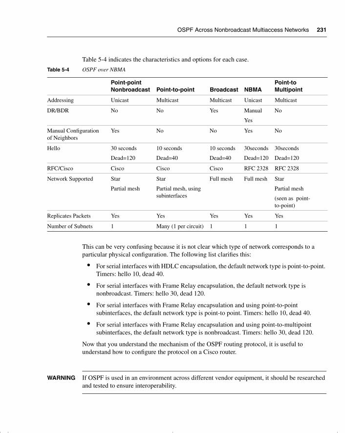
OSPF Across Nonbroadcast Multiaccess Networks 231
Table 5-4 indicates the characteristics and options for each case.
This can be very confusing because it is not clear which type of network corresponds to a particular physical configuration. The following list clarifies this:
• For serial interfaces with HDLC encapsulation, the default network type is point-to-point. Timers: hello 10, dead 40.
• For serial interfaces with Frame Relay encapsulation, the default network type is nonbroadcast. Timers: hello 30, dead 120.
• For serial interfaces with Frame Relay encapsulation and using point-to-point subinterfaces, the default network type is point-to point. Timers: hello 10, dead 40.
• For serial interfaces with Frame Relay encapsulation and using point-to-multipoint subinterfaces, the default network type is nonbroadcast. Timers: hello 30, dead 120.
Now that you understand the mechanism of the OSPF routing protocol, it is useful to understand how to configure the protocol on a Cisco router.
WARNING If OSPF is used in an environment across different vendor equipment, it should be researched and tested to ensure interoperability.
Table 5-4 OSPF over NBMA
Point-point Nonbroadcast Point-to-point Broadcast NBMA
Point-to Multipoint
Addressing Unicast Multicast Multicast Unicast Multicast
DR/BDR No No Yes Manual
Yes
No
Manual Configuration of Neighbors
Yes No No Yes No
Hello 30 seconds
Dead=120
10 seconds
Dead=40
10 seconds
Dead=40
30seconds
Dead=120
30seconds
Dead=120
RFC/Cisco Cisco Cisco Cisco RFC 2328 RFC 2328
Network Supported Star
Partial mesh
Star
Partial mesh, using subinterfaces
Full mesh Full mesh Star
Partial mesh
(seen as point-to-point)
Replicates Packets Yes Yes Yes Yes Yes
Number of Subnets 1 Many (1 per circuit) 1 1 1
chpt_01.book Page 231 Thursday, December 21, 2000 6:22 PM
232 Chapter 5: Using OSPF in a Single Area
Configuring OSPF in a Single AreaWhen configuring any device, it is important to establish why you are configuring the system and what you are trying to achieve.
This section examines the configuration of a Cisco router for OSPF within a single area. The commands are few and extremely simple; the implications are somewhat more difficult.
This section covers the following:
• Configuration of OSPF
— Required configuration
— Optional configuration
• Commands
— What each configuration command achieves
— How the configuration command achieves its goal
An example of a working configuration that uses the commands discussed in this section illustrates the use of those commands in context. A corresponding figure illustrates the configuration.
Required Commands for Configuring OSPF on an Internal RouterThe router to be configured is the 2500, an internal router within a single area. The router needs to understand how to participate in the OSPF network. Therefore, it requires the following:
• The OSPF process—The routing protocol needs to be started on the router.
• Participating router interfaces—The router may not want to have all its interfaces send or receive OSPF routing updates. A classic example is a dialup line to a remote office. If there were only one subnet at the remote office, it would be more efficient to use default and static route commands because any updates would dial the line.
• Identification of the area—The router will define which area it is in on a per-interface basis.
• A router ID—This allows the router to be identified by the other routers in the network. The ID of the router advertising a link is used to determine the next logical hop, for example, if that link is used in the path selection to a remote network.
The following two commands are required for configuring OSPF on a single internal router:
• OSPF process command
• OSPF network command
chpt_01.book Page 232 Thursday, December 21, 2000 6:22 PM
Configuring OSPF in a Single Area 233
Enabling The OSPF Routing ProtocolBy default (unless the SETUP script is used), there is no IP routing protocol running on the Cisco router. This is not true of other protocols, however; for example, if an IPX network address is configured on an interface, the IPX RIP process will be automatically started.
To configure OSPF as the routing protocol, use the following command:
router ospf process number
Here, process number is a number local to the router. It is possible to have more than one process running on a router, although this is an unusual and expensive configuration in terms of router resources. The process number does not have to be the same on every router in the area or the autonomous system. In the interest of sanity, however, many administrators make it the same number.
NOTE A common error in configuration is to confuse the process ID with the router ID or the area ID. These are not related in any way. The process ID is simply a mechanism to allow more than one process to be configured on a router. The router ID is the mechanism by which a router is identified within the OSPF domain, and the area ID is a mechanism of grouping routers that share full knowledge of OSPF-derived routes within the OSPF domain.
The OSPF network CommandAlthough OSPF has been turned on, it has no information on how to operate. The networks that are to participate in the OSPF updates, and the area that they reside in, must be defined. If the following information is not specified, the process will have nothing to do and will die:
network network number wildcard mask area area number
This command deserves a moment’s explanation because it is the cause of many errors in configuration.
The network command in OSPF plays a similar role to that of the network command in RIP or IGRP. The difference is the level of granularity afforded to the administrator. In RIP and IGRP, the network command is defined at the class level. In OSPF, it is possible to identify the specific address of an interface.
What the network Command Will DoAfter the network command has been entered, OSPF identifies which interfaces are participating in OSPF by comparing the interface IP address with the address given in the network command, filtered through the wildcard mask. The wildcard mask states how much of the address to pay attention to. It could just look at the class of address, such as everything in
chpt_01.book Page 233 Thursday, December 21, 2000 6:22 PM
234 Chapter 5: Using OSPF in a Single Area
network 10.0.0.0, for example. At the other extreme, it can be more specific and identify an interface address. All interfaces that match the given network number will reside in the area specified in the network command.
WARNING Take great care in the wildcard mask. Remember that it follows the same format as the wildcard mask in an access list. It is extremely easy to make errors in the configuration, and those errors may be difficult to find.
After identifying the interfaces on the router that are participating in the OSPF domain, the following happens:
• Updates will be received on the interface.
• Updates will be sent out of the interfaces.
• The interface will be placed in the defined area.
• If appropriate, the Hello protocol will be propagated. Depending on the interface type, a default hello and dead interval are defined (see Table 5-4).
This network command has many of the same characteristics as an access list. The wildcard mask has the same format and enables you to group interfaces into an area. It follows the same top-down logic of a link list that you saw before in configuring access lists in Chapter 2, “Managing Scalable Network Growth.”
NOTE If there are stub networks connected to a router, it is useful to issue the command redistribute connected subnets. This command is issued as part of the router process configuration, and it includes the connected subnets in OSPF advertisements without actually running OSPF on them. This is very useful for real OSPF configurations, particularly those that involve WAN pay-per-packet, low-bandwidth links.
Configuration ExamplesThe following examples show how one command can cover all router interfaces and also how each individual interface can be specified.
Given a router with six interfaces, three with addresses in the 10.0.0.0 class and three with addresses in the 172.16.0.0 class, the following would configure all interfaces to participate in OSPF Area 0:
network 0.0.0.0 255.255.255.255 area 0
chpt_01.book Page 234 Thursday, December 21, 2000 6:22 PM
Configuring OSPF in a Single Area 235
The following would have only the interfaces addressed from 10.0.0.0 participating in OSPF Area 0:
network 10.0.0.0 0.255.255.255 area 0
The next example shows only two specific interfaces participating in OSPF Area 0:
network 10.12.0.1 0.0.0.0 area 0network 172.16.15.1 0.0.0.0 area 0
As with an access list, the top-down logic should be thought through carefully. The most specific criteria must be defined before the general.
Why Is the network Command So Complex?It is reasonable to ask why OSPF is so much more complex than either IGRP or RIP in this instance. The answer is that the level of precision available in the OSPF network command provides the capability to place different interfaces into different areas on the same router. The need for this complexity is not obvious in this example because an internal router is being configured within a single area.
The flexibility in defining which interfaces reside in which area is considered in Chapter 6, in the section “Configuration Commands for a Multiarea OSPF Network.”
Options for Configuring OSPF on an Internal RouterThe following are not necessary to make OSPF function properly within an area. However, they may be useful in your network design:
• The loopback interface
• The cost command
• The priority command
These are discussed in greater detail in the next sections.
The Loopback Interface and the Router IDThe router needs an ID to participate in the OSPF domain. The router ID is used to identify the source of LSA updates as shown in the OSPF database. This ID takes the form of an IP address. This address can either be defined by the administrator or left to the whim of the router. Most people define the ID so that it is easier to track events in the network, for internal documentation, and for other system-administration purposes.
chpt_01.book Page 235 Thursday, December 21, 2000 6:22 PM
236 Chapter 5: Using OSPF in a Single Area
The Default Router ID SelectionIf no ID is stated, the router will take the highest IP address configured on the router. Although it is unlikely that this addresses will change, it is possible. From an administrative viewpoint, such a change would introduce an unnecessary level of chaos into the network.
Manual Configuration of Router IDThere is no command to define the OSPF router ID, but the Cisco rule states that the router ID will be taken from the address of the loopback interface. If no loopback interface is defined, it uses the highest IP address configured on the router.
The loopback interface is a virtual interface that does not exist physically. This characteristic makes it very powerful: If it does not exist, it can never go down. Therefore, the OSPF network is not vulnerable to hardware interface problems.
Having created a loopback interface, it needs an IP address. Many organizations choose a different addressing scheme for the loopbacks to distinguish them easily when troubleshooting. It is important to remember that each interface requires a separate subnet. The use of a private address from RFC 1918 may be wise in terms of both addressing issues and administrative documentation.
The following shows how to configure a loopback interface:
interface loopback interface numberip address ip address subnet-mask
NOTE When designing a network, consider whether to include the loopback interface address in the network commands. There are both advantages and disadvantages to this, and they should be researched in any network design. If the organization is running out of valid addresses, it may be advisable to use the loopback address only as a router ID and not insert it into the routing table. The disadvantage of this configuration is that it cannot be pinged for testing. This is known as a bogus RID. The preferred configuration would be to have an address in the routing table. These addresses can actually have a 32-bit mask.
Changing the Default Metric Using the cost CommandAnother command that may be useful is the cost command. This command manually overrides the default cost that the router assigns to the interface. The default cost is calculated based on the speed of the outgoing interface.
The cost command syntax is as follows:
ip ospf cost cost
chpt_01.book Page 236 Thursday, December 21, 2000 6:22 PM
Configuring OSPF in a Single Area 237
A lower cost increases the likelihood that the interface will be selected as the best or shortest path. The range of values configurable for the cost of a link is 1 to 65535.
In general, the path cost in Cisco routers is calculated using the formula 108/ bandwidth. Table 5-5 shows examples of default costs.
NOTE Serial lines have many different speeds. The default bandwidth is 1.544 Mbps. If the line is a slower speed, use the bandwidth command to specify the real link speed. The cost of the link will then change to correspond to the bandwidth that you configured.
It is now possible to control how OSPF calculates default metrics for the interface. Use the ospf auto-cost reference-bandwidth router global configuration command to change the numerator of the above OSPF cost formula:
ospf auto-cost reference-bandwidth reference-bandwidth
Here, reference-bandwidth is in megabytes per second. The range is 1 to 4294967; the default is 100.
This means that a cost of 1 = 100 Mbps, and a cost of 10 = 100/10 = 10 Mbps. If you’re moving to gigabit, then you would want 1000 Mbps = 1 Gbps.
Any change using this command should be done on all routers in the AS so that they all use the same formula to calculate cost. The value set by the ip ospf cost command overrides the cost resulting from the auto-cost reference-bandwidth command.
In the Cisco IOS documentation, the auto-cost command is documented as ospf auto-cost. However, auto-cost is the actual command in the Cisco IOS.
cost Command Design ConsiderationsConsiderations in using the cost command include the following:
• Never change defaults unless you can explain why the change is necessary. Reasons for using the cost option in OSPF include the following:
— You want to maintain interoperability among different vendors running OSPF.
Table 5-5 Default Costs in OSPF
Link Type Default Cost
56-kbps serial link 1785
T1 (1.544-Mbps serial link) 64
Ethernet 10
16-Mbps Token Ring 6
chpt_01.book Page 237 Thursday, December 21, 2000 6:22 PM
238 Chapter 5: Using OSPF in a Single Area
— There is a design reason to choose a different path than the one selected by the Cisco default metric.
— You want to allow greater granularity in the application of the cost metric.
• If the default is to be overridden by the manual configuration, it is important that it is done with due consideration to the physical and logical topology map of the network. Any change to the metric may change the traffic patterns in the network.
Determining the Designated Router Using the priority CommandThe last command to consider is the priority command. This command is used to determine the designated and backup designated routers on a multiaccess link. Remember that the Hello protocol is the mechanism by which the designated routers are elected. To be “up for election,” the priority must be a positive integer between 1 and 255. If the priority is 0, the router cannot participate in the election. The higher the priority, the greater the likelihood of being elected. If no priority is set, all Cisco routers have a default priority of 1, and the router ID is used as a tiebreaker. In effect, this means that the router ID is the determining factor.
priority Command Design ConsiderationsReasons for changing the router priority include the following:
• The router has greater CPU and memory than the others do on the LAN.
• The router is the most reliable router on the segment.
• All the other routers on the LAN connect to stub networks. They all form the access layer of the network.
• There are point-to-multipoint connections in an NBMA cloud, and the hub router needs to be configured as the centralized resource, requiring it to be the designated router.
• The router is an ABR, and you don’t want it to consume more resources as a designated router.
Seeing how these commands work in context makes their use and functionality much more apparent.
A Working Configuration of OSPF on a Single RouterExample 5-1 is a working configuration tested for verification. It should be used in conjunction with Figure 5-11.
chpt_01.book Page 238 Thursday, December 21, 2000 6:22 PM
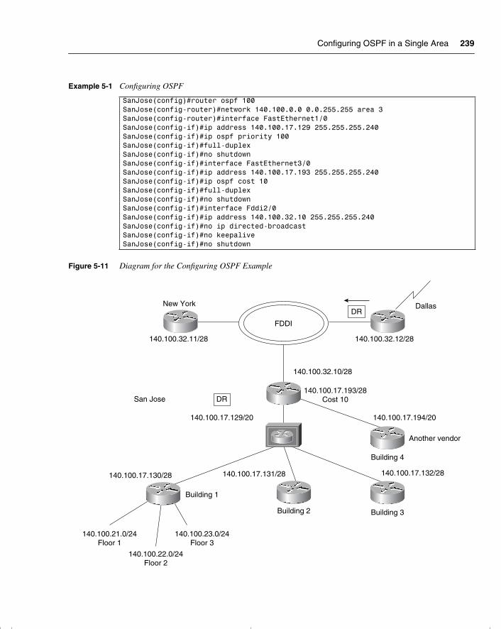
Configuring OSPF in a Single Area 239
Figure 5-11 Diagram for the Configuring OSPF Example
Example 5-1 Configuring OSPF
SanJose(config)#router ospf 100SanJose(config-router)#network 140.100.0.0 0.0.255.255 area 3SanJose(config-router)#interface FastEthernet1/0SanJose(config-if)#ip address 140.100.17.129 255.255.255.240SanJose(config-if)#ip ospf priority 100SanJose(config-if)#full-duplexSanJose(config-if)#no shutdownSanJose(config-if)#interface FastEthernet3/0SanJose(config-if)#ip address 140.100.17.193 255.255.255.240SanJose(config-if)#ip ospf cost 10SanJose(config-if)#full-duplexSanJose(config-if)#no shutdownSanJose(config-if)#interface Fddi2/0SanJose(config-if)#ip address 140.100.32.10 255.255.255.240SanJose(config-if)#no ip directed-broadcastSanJose(config-if)#no keepaliveSanJose(config-if)#no shutdown
FDDI
New York Dallas
140.100.32.11/28
140.100.17.129/20
140.100.32.12/28
140.100.32.10/28
140.100.17.193/28Cost 10
140.100.17.194/20
140.100.17.132/28140.100.17.131/28140.100.17.130/28
140.100.21.0/24Floor 1
140.100.23.0/24Floor 3
140.100.22.0/24Floor 2
DR
DR
San Jose
Another vendor
Building 4
Building 3Building 2
Building 1
chpt_01.book Page 239 Thursday, December 21, 2000 6:22 PM
240 Chapter 5: Using OSPF in a Single Area
Configuring OSPF over an NBMA TopologyThe design considerations of running OSPF over an NBMA topology are outside the scope of this book, but it is important to research this area because it speaks to the configuration choices that will be made. However, one of the common choices on a partially meshed network illustrates the kind of decisions that need to be made.
If the network is partially meshed, then the choice to use only point-to-point subnets can waste addresses. If a point-to-multipoint configuration is chosen, the network uses one subnet, and there is no DR/BDR negotiation. This has the advantage of saving addresses but behaving as if it is a series of point-to-point links.
When the decision is made as to which technology is to be implemented, the configuration is straightforward. The choice is defined on the interface as a network command. The network command syntax is as follows:
ip ospf network {broadcast | non-broadcast | {point-to-multipoint [non-broadcast]}}
Table 5-6 explains the command.
For the default encapsulations and hello timers, refer to Table 5-4.
Configuring OSPF in NBMA ModeIn NBMA mode, the design considerations are imperative because the selection of the DR and BDR need to have physical connectivity to all routers in the NBMA cloud. Remember that this is a nonbroadcast environment, so the DR and BDR must be configured with a static list of the other routers attached to the cloud so that they can become neighbors and create adjacencies. This is achieved with the use of the neighbor command.
NOTE Other technologies have superceded the need to manually configure the neighbors.
Table 5-6 The ip ospf network Command
Option Description
nonbroadcast Sets the network mode to nonbroadcast multiaccess (NBMA mode). This is the default mode for serial interfaces with Frame Relay encapsulation and point-to-multipoint subinterfaces.
point-to-multipoint Sets the network mode to point-to-multipoint
point-to-multipoint nonbroadcast
(Optional) Sets the network mode to point-to-multipoint nonbroadcast.
broadcast Sets the network mode to broadcast.
point-to-point Sets the network mode to point-to-point. This is the default mode for point-to-point subinterfaces.
chpt_01.book Page 240 Thursday, December 21, 2000 6:22 PM
Configuring OSPF over an NBMA Topology 241
The syntax of the command is as follows:
neighbor ip-address [priority number ] [poll-interval sec] [cost number]
The neighbor command is used to configure OSPF routers interconnecting to nonbroadcast networks. The different options used with the neighbor command are explained in Table 5-7.
Example 5-2 shows how the command is used.
NOTE NBMA mode is used by default, so there is no need for the ip ospf network non-broadcast command. However, neighbor statements are necessary.
Table 5-7 The OSPF neighbor Command
neighbor Command Description
ip-address Interface IP address of the neighbor.
priority number (Optional) An 8-bit number indicating the likelihood of this router being elected as the BDR or the DR. The default is 0. This keyword does not apply to point-to-multipoint mode interfaces because no BDR or DR is selected.
poll-interval sec (Optional) Unsigned integer value reflecting the poll interval. RFC 1247 recommends that this value be much larger than the hello interval. The default is 120 seconds (2 minutes). This keyword does not apply to point-to-multipoint mode interfaces.
If a neighboring router has become inactive (hello packets have not been seen for the router dead interval period), it may still be necessary to send hello packets to the dead neighbor. These hello packets will be sent at a reduced rate called the poll interval.
cost number (Optional) Value that assigns a cost or metric. It takes the form of an integer from 1 to 65535. Neighbors with no specific cost configured will assume the cost of the interface, based on the bandwidth or the ip ospf cost command. On point-to-multipoint mode interfaces, this is the only keyword and argument that make sense. This keyword does not apply to NBMA mode networks.
Example 5-2 The OSPF neighbor Command
ROUTER(config)#interface Serial0ROUTER(config-if)#ip address 131.144.10.100 255.255.255.0ROUTER(config-if)#encapsulation frame-relayROUTER(config-if)#ip ospf network non-broadcastROUTER(config)#router ospf 1ROUTER(config-router)#network 131.144.10.100 0.0.0.255 area 0ROUTER(config-router)#neighbor 131.144.10.2ROUTER(config-router)#neighbor 131.144.10.3ROUTER(config-router)#neighbor 131.144.10.5
chpt_01.book Page 241 Thursday, December 21, 2000 6:22 PM
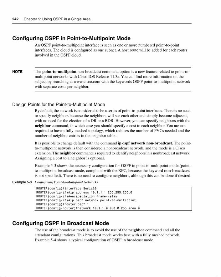
242 Chapter 5: Using OSPF in a Single Area
Configuring OSPF in Point-to-Multipoint Mode An OSPF point-to-multipoint interface is seen as one or more numbered point-to-point interfaces. The cloud is configured as one subnet. A host route will be added for each router involved in the OSPF cloud.
NOTE The point-to-multipoint non-broadcast command option is a new feature related to point-to-multipoint networks with Cisco IOS Release 11.3a. You can find more information on the subject by searching at www.cisco.com with the keywords OSPF point-to-multipoint network with separate costs per neighbor.
Design Points for the Point-to-Multipoint ModeBy default, the network is considered to be a series of point-to-point interfaces. There is no need to specify neighbors because the neighbors will see each other and simply become adjacent, with no need for the election of a DR or a BDR. However, you can specify neighbors with the neighbor command, in which case you should specify a cost to each neighbor. You are not required to have a fully meshed topology, which reduces the number of PVCs needed and the number of neighbor entries in the neighbor table.
It is possible to change default with the command ip ospf network non-broadcast. The point-to-multipoint network is then considered a nonbroadcast network, and the mode is a Cisco extension. The neighbor command is required to identify neighbors in a nonbroadcast network. Assigning a cost to a neighbor is optional.
Example 5-3 shows the necessary configuration for OSPF in point-to-multipoint mode (point-to-multipoint broadcast mode, compliant with the RFC, because the keyword non-broadcast is not specified). There is no need to configure neighbors, although this can be done if desired.
Configuring OSPF in Broadcast ModeThe use of the broadcast mode is to avoid the use of the neighbor command and all the attendant configurations. This broadcast mode works best with a fully meshed network. Example 5-4 shows a typical configuration of OSPF in broadcast mode.
Example 5-3 Configuring Point-to-Multipoint Networks
ROUTER(config)#interface Serial0ROUTER(config-if)#ip address 10.1.1.1 255.255.255.0ROUTER(config-if)#encapsulation frame-relayROUTER(config-if)#ip ospf network point-to-multipointROUTER(config)#router ospf 1ROUTER(config-router)#network 10.1.1.0 0.0.0.255 area 0
chpt_01.book Page 242 Thursday, December 21, 2000 6:22 PM
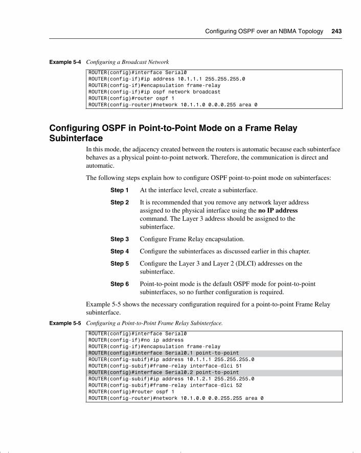
Configuring OSPF over an NBMA Topology 243
Configuring OSPF in Point-to-Point Mode on a Frame Relay Subinterface
In this mode, the adjacency created between the routers is automatic because each subinterface behaves as a physical point-to-point network. Therefore, the communication is direct and automatic.
The following steps explain how to configure OSPF point-to-point mode on subinterfaces:
Step 1 At the interface level, create a subinterface.
Step 2 It is recommended that you remove any network layer address assigned to the physical interface using the no IP address command. The Layer 3 address should be assigned to the subinterface.
Step 3 Configure Frame Relay encapsulation.
Step 4 Configure the subinterfaces as discussed earlier in this chapter.
Step 5 Configure the Layer 3 and Layer 2 (DLCI) addresses on the subinterface.
Step 6 Point-to-point mode is the default OSPF mode for point-to-point subinterfaces, so no further configuration is required.
Example 5-5 shows the necessary configuration required for a point-to-point Frame Relay subinterface.
Example 5-4 Configuring a Broadcast Network
ROUTER(config)#interface Serial0ROUTER(config-if)#ip address 10.1.1.1 255.255.255.0ROUTER(config-if)#encapsulation frame-relayROUTER(config-if)#ip ospf network broadcastROUTER(config)#router ospf 1ROUTER(config-router)#network 10.1.1.0 0.0.0.255 area 0
Example 5-5 Configuring a Point-to-Point Frame Relay Subinterface.
ROUTER(config)#interface Serial0ROUTER(config-if)#no ip addressROUTER(config-if)#encapsulation frame-relayROUTER(config)#interface Serial0.1 point-to-pointROUTER(config-subif)#ip address 10.1.1.1 255.255.255.0ROUTER(config-subif)#frame-relay interface-dlci 51ROUTER(config)#interface Serial0.2 point-to-pointROUTER(config-subif)#ip address 10.1.2.1 255.255.255.0ROUTER(config-subif)#frame-relay interface-dlci 52ROUTER(config)#router ospf 1ROUTER(config-router)#network 10.1.0.0 0.0.255.255 area 0
chpt_01.book Page 243 Thursday, December 21, 2000 6:22 PM
244 Chapter 5: Using OSPF in a Single Area
NOTE The shading in the previous example shows the configuration required to create a subinterface.
Of course, it is imperative to check any configuration on a network device because any errors could potentially bring down the entire network. To verify the configuration, there is a wealth of Cisco commands. They are covered in the following section.
Checking the Configuration of OSPF on a Single RouterThe following set of commands is invaluable in both configuration and maintenance of a live network. These commands are particularly useful in troubleshooting the network. As such, these commands are a necessary set of tools for use on a daily basis, for the CCNP/CCDP Routing exam as well as the CCIE lab exam:
• show ip ospf—Shows the OSPF process and its details—for example, how many times the router has recalculated its routing table.
• show ip ospf database—Shows the contents of the topological database.
• show ip ospf interface—Gives information on how OSPF has been configured on each interface. Typing errors are easily seen with this command.
• show ip ospf neighbor—Displays all the information about the relationship that the router has with its neighbors—for example, the status of communication and whether it is initializing or transferring DDP packets.
• show ip protocols—Enables you to view the IP configuration on the router. This command is useful because it shows not only the interfaces, but the configuration of the IP routing protocols as well.
• show ip route—Shows detailed information on the networks that the router is aware of and the preferred paths to those networks. Also gives the next logical hop as the next step in the path (this command is covered in detail in Chapter 4, “IP Routing Principles”).
Understanding the output of these commands is important. This is not just because the output may constitute questions on the exam, but because the capability to analyze what is happening on the network demands a thorough understanding of the concepts explained in this chapter. An understanding of the concepts in this chapter is required in interpreting the output of a show command.
The OSPF show commands are highly detailed and give a comprehensive understanding of the state of the network.
chpt_01.book Page 244 Thursday, December 21, 2000 6:22 PM
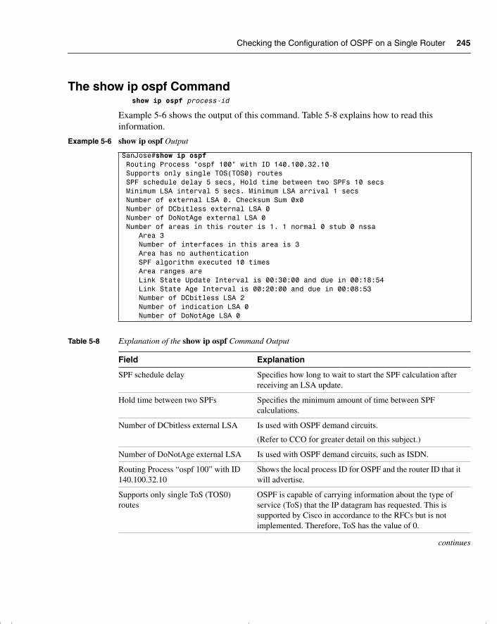
Checking the Configuration of OSPF on a Single Router 245
The show ip ospf Commandshow ip ospf process-id
Example 5-6 shows the output of this command. Table 5-8 explains how to read this information.
Example 5-6 show ip ospf Output
SanJose#show ip ospf Routing Process "ospf 100" with ID 140.100.32.10 Supports only single TOS(TOS0) routes SPF schedule delay 5 secs, Hold time between two SPFs 10 secs Minimum LSA interval 5 secs. Minimum LSA arrival 1 secs Number of external LSA 0. Checksum Sum 0x0 Number of DCbitless external LSA 0 Number of DoNotAge external LSA 0 Number of areas in this router is 1. 1 normal 0 stub 0 nssa Area 3 Number of interfaces in this area is 3 Area has no authentication SPF algorithm executed 10 times Area ranges are Link State Update Interval is 00:30:00 and due in 00:18:54 Link State Age Interval is 00:20:00 and due in 00:08:53 Number of DCbitless LSA 2 Number of indication LSA 0 Number of DoNotAge LSA 0
Table 5-8 Explanation of the show ip ospf Command Output
Field Explanation
SPF schedule delay Specifies how long to wait to start the SPF calculation after receiving an LSA update.
Hold time between two SPFs Specifies the minimum amount of time between SPF calculations.
Number of DCbitless external LSA Is used with OSPF demand circuits.
(Refer to CCO for greater detail on this subject.)
Number of DoNotAge external LSA Is used with OSPF demand circuits, such as ISDN.
Routing Process “ospf 100” with ID 140.100.32.10
Shows the local process ID for OSPF and the router ID that it will advertise.
Supports only single ToS (TOS0) routes
OSPF is capable of carrying information about the type of service (ToS) that the IP datagram has requested. This is supported by Cisco in accordance to the RFCs but is not implemented. Therefore, ToS has the value of 0.
continues
chpt_01.book Page 245 Thursday, December 21, 2000 6:22 PM
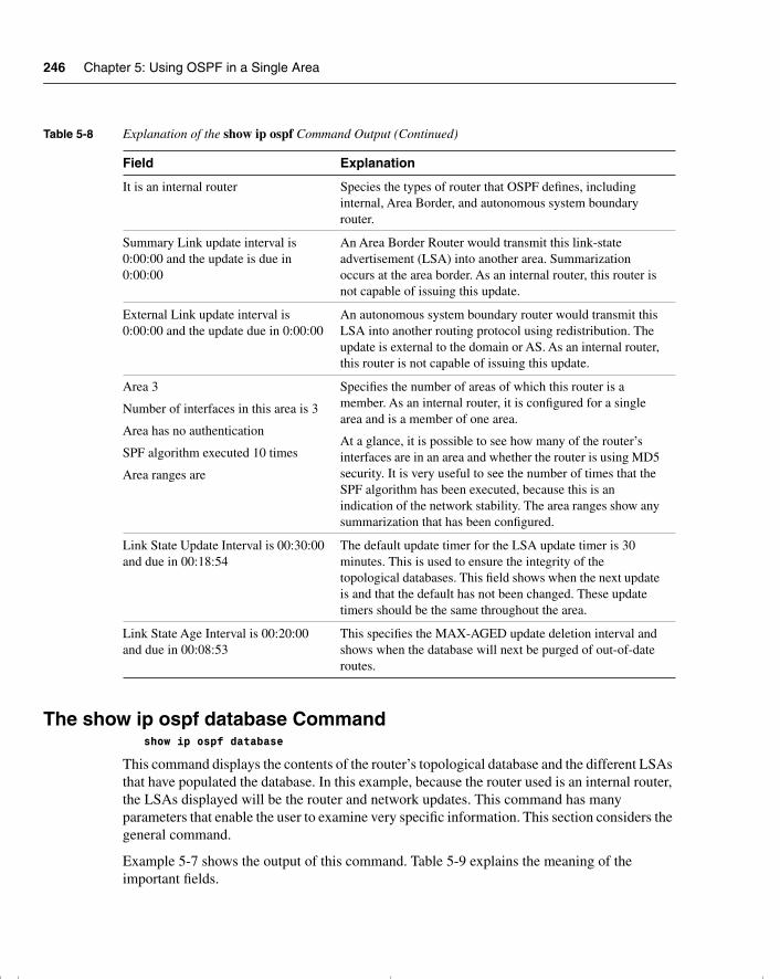
246 Chapter 5: Using OSPF in a Single Area
The show ip ospf database Commandshow ip ospf database
This command displays the contents of the router’s topological database and the different LSAs that have populated the database. In this example, because the router used is an internal router, the LSAs displayed will be the router and network updates. This command has many parameters that enable the user to examine very specific information. This section considers the general command.
Example 5-7 shows the output of this command. Table 5-9 explains the meaning of the important fields.
It is an internal router Species the types of router that OSPF defines, including internal, Area Border, and autonomous system boundary router.
Summary Link update interval is 0:00:00 and the update is due in 0:00:00
An Area Border Router would transmit this link-state advertisement (LSA) into another area. Summarization occurs at the area border. As an internal router, this router is not capable of issuing this update.
External Link update interval is 0:00:00 and the update due in 0:00:00
An autonomous system boundary router would transmit this LSA into another routing protocol using redistribution. The update is external to the domain or AS. As an internal router, this router is not capable of issuing this update.
Area 3
Number of interfaces in this area is 3
Area has no authentication
SPF algorithm executed 10 times
Area ranges are
Specifies the number of areas of which this router is a member. As an internal router, it is configured for a single area and is a member of one area.
At a glance, it is possible to see how many of the router’s interfaces are in an area and whether the router is using MD5 security. It is very useful to see the number of times that the SPF algorithm has been executed, because this is an indication of the network stability. The area ranges show any summarization that has been configured.
Link State Update Interval is 00:30:00 and due in 00:18:54
The default update timer for the LSA update timer is 30 minutes. This is used to ensure the integrity of the topological databases. This field shows when the next update is and that the default has not been changed. These update timers should be the same throughout the area.
Link State Age Interval is 00:20:00 and due in 00:08:53
This specifies the MAX-AGED update deletion interval and shows when the database will next be purged of out-of-date routes.
Table 5-8 Explanation of the show ip ospf Command Output (Continued)
Field Explanation
chpt_01.book Page 246 Thursday, December 21, 2000 6:22 PM
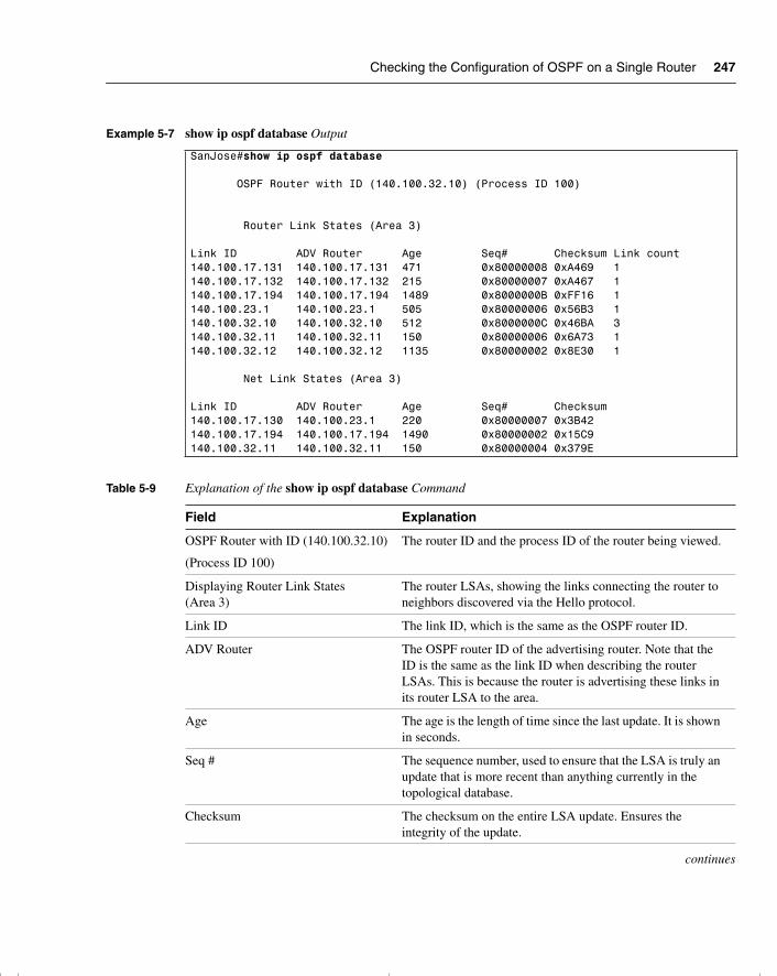
Checking the Configuration of OSPF on a Single Router 247
Example 5-7 show ip ospf database Output
SanJose#show ip ospf database
OSPF Router with ID (140.100.32.10) (Process ID 100)
Router Link States (Area 3)
Link ID ADV Router Age Seq# Checksum Link count140.100.17.131 140.100.17.131 471 0x80000008 0xA469 1140.100.17.132 140.100.17.132 215 0x80000007 0xA467 1140.100.17.194 140.100.17.194 1489 0x8000000B 0xFF16 1140.100.23.1 140.100.23.1 505 0x80000006 0x56B3 1140.100.32.10 140.100.32.10 512 0x8000000C 0x46BA 3140.100.32.11 140.100.32.11 150 0x80000006 0x6A73 1140.100.32.12 140.100.32.12 1135 0x80000002 0x8E30 1
Net Link States (Area 3)
Link ID ADV Router Age Seq# Checksum140.100.17.130 140.100.23.1 220 0x80000007 0x3B42 140.100.17.194 140.100.17.194 1490 0x80000002 0x15C9 140.100.32.11 140.100.32.11 150 0x80000004 0x379E
Table 5-9 Explanation of the show ip ospf database Command
Field Explanation
OSPF Router with ID (140.100.32.10)
(Process ID 100)
The router ID and the process ID of the router being viewed.
Displaying Router Link States (Area 3)
The router LSAs, showing the links connecting the router to neighbors discovered via the Hello protocol.
Link ID The link ID, which is the same as the OSPF router ID.
ADV Router The OSPF router ID of the advertising router. Note that the ID is the same as the link ID when describing the router LSAs. This is because the router is advertising these links in its router LSA to the area.
Age The age is the length of time since the last update. It is shown in seconds.
Seq # The sequence number, used to ensure that the LSA is truly an update that is more recent than anything currently in the topological database.
Checksum The checksum on the entire LSA update. Ensures the integrity of the update.
continues
chpt_01.book Page 247 Thursday, December 21, 2000 6:22 PM
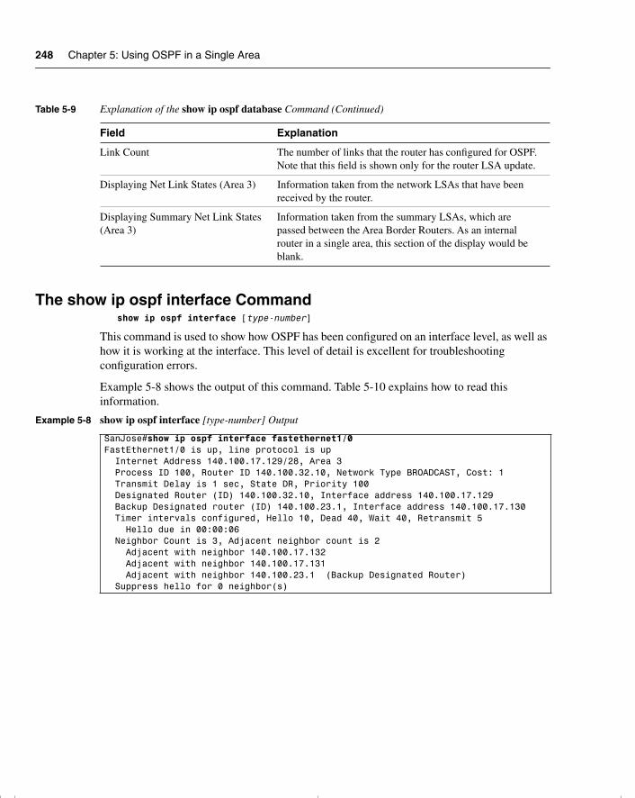
248 Chapter 5: Using OSPF in a Single Area
The show ip ospf interface Commandshow ip ospf interface [type-number]
This command is used to show how OSPF has been configured on an interface level, as well as how it is working at the interface. This level of detail is excellent for troubleshooting configuration errors.
Example 5-8 shows the output of this command. Table 5-10 explains how to read this information.
Link Count The number of links that the router has configured for OSPF. Note that this field is shown only for the router LSA update.
Displaying Net Link States (Area 3) Information taken from the network LSAs that have been received by the router.
Displaying Summary Net Link States (Area 3)
Information taken from the summary LSAs, which are passed between the Area Border Routers. As an internal router in a single area, this section of the display would be blank.
Example 5-8 show ip ospf interface [type-number] Output
SanJose#show ip ospf interface fastethernet1/0FastEthernet1/0 is up, line protocol is up Internet Address 140.100.17.129/28, Area 3 Process ID 100, Router ID 140.100.32.10, Network Type BROADCAST, Cost: 1 Transmit Delay is 1 sec, State DR, Priority 100 Designated Router (ID) 140.100.32.10, Interface address 140.100.17.129 Backup Designated router (ID) 140.100.23.1, Interface address 140.100.17.130 Timer intervals configured, Hello 10, Dead 40, Wait 40, Retransmit 5 Hello due in 00:00:06 Neighbor Count is 3, Adjacent neighbor count is 2 Adjacent with neighbor 140.100.17.132 Adjacent with neighbor 140.100.17.131 Adjacent with neighbor 140.100.23.1 (Backup Designated Router) Suppress hello for 0 neighbor(s)
Table 5-9 Explanation of the show ip ospf database Command (Continued)
Field Explanation
chpt_01.book Page 248 Thursday, December 21, 2000 6:22 PM
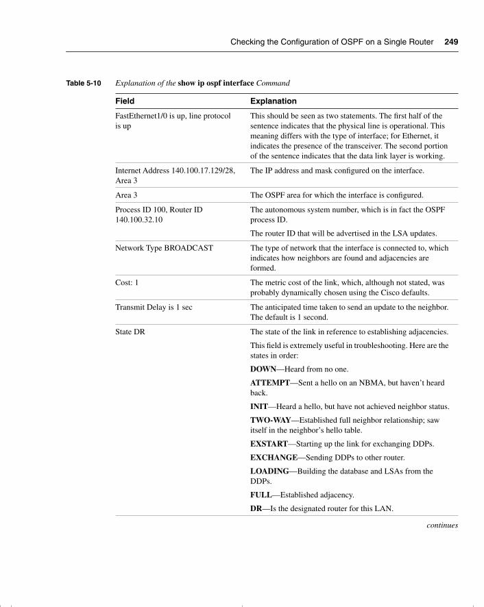
Checking the Configuration of OSPF on a Single Router 249
Table 5-10 Explanation of the show ip ospf interface Command
Field Explanation
FastEthernet1/0 is up, line protocol is up
This should be seen as two statements. The first half of the sentence indicates that the physical line is operational. This meaning differs with the type of interface; for Ethernet, it indicates the presence of the transceiver. The second portion of the sentence indicates that the data link layer is working.
Internet Address 140.100.17.129/28, Area 3
The IP address and mask configured on the interface.
Area 3 The OSPF area for which the interface is configured.
Process ID 100, Router ID 140.100.32.10
The autonomous system number, which is in fact the OSPF process ID.
The router ID that will be advertised in the LSA updates.
Network Type BROADCAST The type of network that the interface is connected to, which indicates how neighbors are found and adjacencies are formed.
Cost: 1 The metric cost of the link, which, although not stated, was probably dynamically chosen using the Cisco defaults.
Transmit Delay is 1 sec The anticipated time taken to send an update to the neighbor. The default is 1 second.
State DR The state of the link in reference to establishing adjacencies.
This field is extremely useful in troubleshooting. Here are the states in order:
DOWN—Heard from no one.
ATTEMPT—Sent a hello on an NBMA, but haven’t heard back.
INIT—Heard a hello, but have not achieved neighbor status.
TWO-WAY—Established full neighbor relationship; saw itself in the neighbor’s hello table.
EXSTART—Starting up the link for exchanging DDPs.
EXCHANGE—Sending DDPs to other router.
LOADING—Building the database and LSAs from the DDPs.
FULL—Established adjacency.
DR—Is the designated router for this LAN.
continues
chpt_01.book Page 249 Thursday, December 21, 2000 6:22 PM
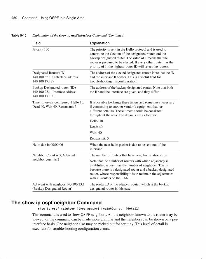
250 Chapter 5: Using OSPF in a Single Area
The show ip ospf neighbor Commandshow ip ospf neighbor [type number] [neighbor-id] [detail]
This command is used to show OSPF neighbors. All the neighbors known to the router may be viewed, or the command can be made more granular and the neighbors can be shown on a per-interface basis. One neighbor also may be picked out for scrutiny. This level of detail is excellent for troubleshooting configuration errors.
Priority 100 The priority is sent in the Hello protocol and is used to determine the election of the designated router and the backup designated router. The value of 1 means that the router is prepared to be elected. If every other router has the priority of 1, the highest router ID will select the routers.
Designated Router (ID) 140.100.32.10, Interface address 140.100.17.129
The address of the elected designated router. Note that the ID and the interface ID differ. This is a useful field for troubleshooting misconfiguration.
Backup Designated router (ID) 140.100.23.1, Interface address 140.100.17.130
The address of the backup designated router. Note that both the ID and the interface are given, and they differ.
Timer intervals configured, Hello 10, Dead 40, Wait 40, Retransmit 5
It is possible to change these timers and sometimes necessary if connecting to another vendor’s equipment that has different defaults. These timers should be consistent throughout the area. The defaults are as follows:
Hello: 10
Dead: 40
Wait: 40
Retransmit: 5
Hello due in 00:00:06 When the next hello packet is due to be sent out of the interface.
Neighbor Count is 3, Adjacent neighbor count is 2
The number of routers that have neighbor relationships.
Note that the number of routers with which adjacency is established is less than the number of neighbors. This is because there is a designated router and a backup designated router, whose responsibility it is to maintain the adjacencies with all routers on the LAN.
Adjacent with neighbor 140.100.23.1 (Backup Designated Router)
The router ID of the adjacent router, which is the backup designated router in this case.
Table 5-10 Explanation of the show ip ospf interface Command (Continued)
Field Explanation
chpt_01.book Page 250 Thursday, December 21, 2000 6:22 PM
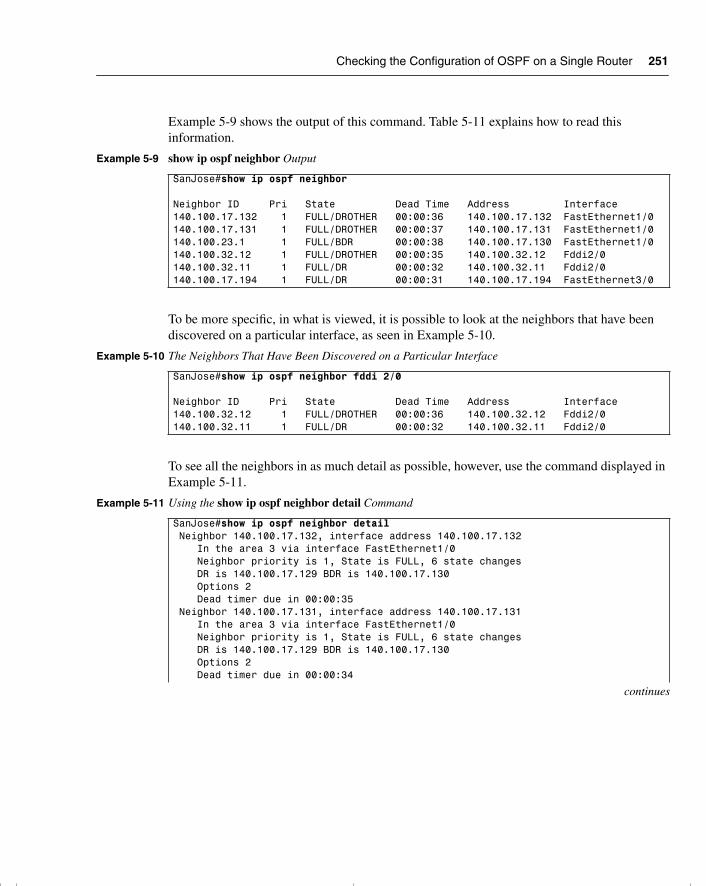
Checking the Configuration of OSPF on a Single Router 251
Example 5-9 shows the output of this command. Table 5-11 explains how to read this information.
To be more specific, in what is viewed, it is possible to look at the neighbors that have been discovered on a particular interface, as seen in Example 5-10.
To see all the neighbors in as much detail as possible, however, use the command displayed in Example 5-11.
Example 5-9 show ip ospf neighbor Output
SanJose#show ip ospf neighbor
Neighbor ID Pri State Dead Time Address Interface140.100.17.132 1 FULL/DROTHER 00:00:36 140.100.17.132 FastEthernet1/0140.100.17.131 1 FULL/DROTHER 00:00:37 140.100.17.131 FastEthernet1/0140.100.23.1 1 FULL/BDR 00:00:38 140.100.17.130 FastEthernet1/0140.100.32.12 1 FULL/DROTHER 00:00:35 140.100.32.12 Fddi2/0140.100.32.11 1 FULL/DR 00:00:32 140.100.32.11 Fddi2/0140.100.17.194 1 FULL/DR 00:00:31 140.100.17.194 FastEthernet3/0
Example 5-10 The Neighbors That Have Been Discovered on a Particular Interface
SanJose#show ip ospf neighbor fddi 2/0
Neighbor ID Pri State Dead Time Address Interface140.100.32.12 1 FULL/DROTHER 00:00:36 140.100.32.12 Fddi2/0140.100.32.11 1 FULL/DR 00:00:32 140.100.32.11 Fddi2/0
Example 5-11 Using the show ip ospf neighbor detail Command
SanJose#show ip ospf neighbor detail Neighbor 140.100.17.132, interface address 140.100.17.132 In the area 3 via interface FastEthernet1/0 Neighbor priority is 1, State is FULL, 6 state changes DR is 140.100.17.129 BDR is 140.100.17.130 Options 2 Dead timer due in 00:00:35 Neighbor 140.100.17.131, interface address 140.100.17.131 In the area 3 via interface FastEthernet1/0 Neighbor priority is 1, State is FULL, 6 state changes DR is 140.100.17.129 BDR is 140.100.17.130 Options 2 Dead timer due in 00:00:34
continues
chpt_01.book Page 251 Thursday, December 21, 2000 6:22 PM
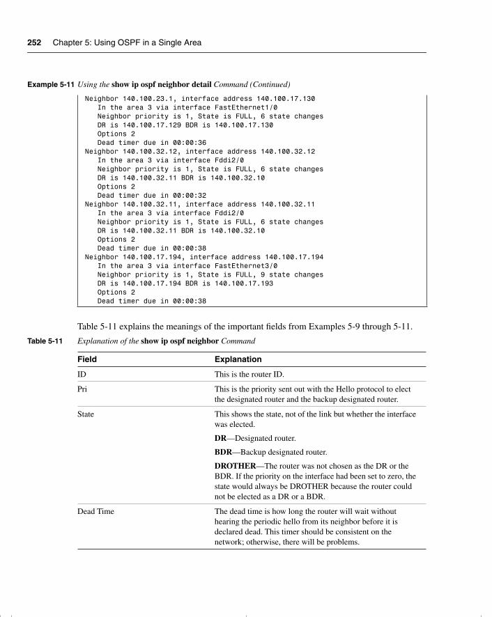
252 Chapter 5: Using OSPF in a Single Area
Table 5-11 explains the meanings of the important fields from Examples 5-9 through 5-11.
Neighbor 140.100.23.1, interface address 140.100.17.130 In the area 3 via interface FastEthernet1/0 Neighbor priority is 1, State is FULL, 6 state changes DR is 140.100.17.129 BDR is 140.100.17.130 Options 2 Dead timer due in 00:00:36 Neighbor 140.100.32.12, interface address 140.100.32.12 In the area 3 via interface Fddi2/0 Neighbor priority is 1, State is FULL, 6 state changes DR is 140.100.32.11 BDR is 140.100.32.10 Options 2 Dead timer due in 00:00:32 Neighbor 140.100.32.11, interface address 140.100.32.11 In the area 3 via interface Fddi2/0 Neighbor priority is 1, State is FULL, 6 state changes DR is 140.100.32.11 BDR is 140.100.32.10 Options 2 Dead timer due in 00:00:38 Neighbor 140.100.17.194, interface address 140.100.17.194 In the area 3 via interface FastEthernet3/0 Neighbor priority is 1, State is FULL, 9 state changes DR is 140.100.17.194 BDR is 140.100.17.193 Options 2 Dead timer due in 00:00:38
Table 5-11 Explanation of the show ip ospf neighbor Command
Field Explanation
ID This is the router ID.
Pri This is the priority sent out with the Hello protocol to elect the designated router and the backup designated router.
State This shows the state, not of the link but whether the interface was elected.
DR—Designated router.
BDR—Backup designated router.
DROTHER—The router was not chosen as the DR or the BDR. If the priority on the interface had been set to zero, the state would always be DROTHER because the router could not be elected as a DR or a BDR.
Dead Time The dead time is how long the router will wait without hearing the periodic hello from its neighbor before it is declared dead. This timer should be consistent on the network; otherwise, there will be problems.
Example 5-11 Using the show ip ospf neighbor detail Command (Continued)
chpt_01.book Page 252 Thursday, December 21, 2000 6:22 PM
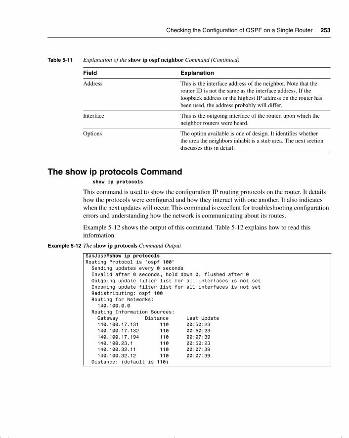
Checking the Configuration of OSPF on a Single Router 253
The show ip protocols Commandshow ip protocols
This command is used to show the configuration IP routing protocols on the router. It details how the protocols were configured and how they interact with one another. It also indicates when the next updates will occur. This command is excellent for troubleshooting configuration errors and understanding how the network is communicating about its routes.
Example 5-12 shows the output of this command. Table 5-12 explains how to read this information.
Address This is the interface address of the neighbor. Note that the router ID is not the same as the interface address. If the loopback address or the highest IP address on the router has been used, the address probably will differ.
Interface This is the outgoing interface of the router, upon which the neighbor routers were heard.
Options The option available is one of design. It identifies whether the area the neighbors inhabit is a stub area. The next section discusses this in detail.
Example 5-12 The show ip protocols Command Output
SanJose#show ip protocolsRouting Protocol is "ospf 100" Sending updates every 0 seconds Invalid after 0 seconds, hold down 0, flushed after 0 Outgoing update filter list for all interfaces is not set Incoming update filter list for all interfaces is not set Redistributing: ospf 100 Routing for Networks: 140.100.0.0 Routing Information Sources: Gateway Distance Last Update 140.100.17.131 110 00:50:23 140.100.17.132 110 00:50:23 140.100.17.194 110 00:07:39 140.100.23.1 110 00:50:23 140.100.32.11 110 00:07:39 140.100.32.12 110 00:07:39 Distance: (default is 110)
Table 5-11 Explanation of the show ip ospf neighbor Command (Continued)
Field Explanation
chpt_01.book Page 253 Thursday, December 21, 2000 6:22 PM
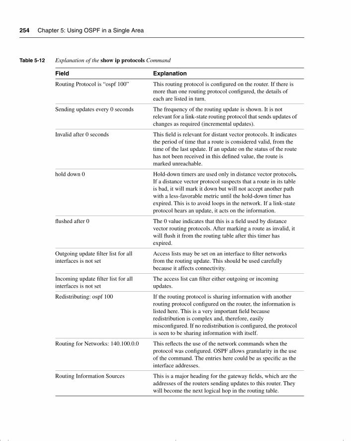
254 Chapter 5: Using OSPF in a Single Area
Table 5-12 Explanation of the show ip protocols Command
Field Explanation
Routing Protocol is “ospf 100” This routing protocol is configured on the router. If there is more than one routing protocol configured, the details of each are listed in turn.
Sending updates every 0 seconds The frequency of the routing update is shown. It is not relevant for a link-state routing protocol that sends updates of changes as required (incremental updates).
Invalid after 0 seconds This field is relevant for distant vector protocols. It indicates the period of time that a route is considered valid, from the time of the last update. If an update on the status of the route has not been received in this defined value, the route is marked unreachable.
hold down 0 Hold-down timers are used only in distance vector protocols. If a distance vector protocol suspects that a route in its table is bad, it will mark it down but will not accept another path with a less-favorable metric until the hold-down timer has expired. This is to avoid loops in the network. If a link-state protocol hears an update, it acts on the information.
flushed after 0 The 0 value indicates that this is a field used by distance vector routing protocols. After marking a route as invalid, it will flush it from the routing table after this timer has expired.
Outgoing update filter list for all interfaces is not set
Access lists may be set on an interface to filter networks from the routing update. This should be used carefully because it affects connectivity.
Incoming update filter list for all interfaces is not set
The access list can filter either outgoing or incoming updates.
Redistributing: ospf 100 If the routing protocol is sharing information with another routing protocol configured on the router, the information is listed here. This is a very important field because redistribution is complex and, therefore, easily misconfigured. If no redistribution is configured, the protocol is seen to be sharing information with itself.
Routing for Networks: 140.100.0.0 This reflects the use of the network commands when the protocol was configured. OSPF allows granularity in the use of the command. The entries here could be as specific as the interface addresses.
Routing Information Sources This is a major heading for the gateway fields, which are the addresses of the routers sending updates to this router. They will become the next logical hop in the routing table.
chpt_01.book Page 254 Thursday, December 21, 2000 6:22 PM
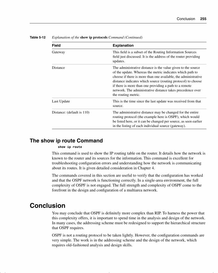
Conclusion 255
The show ip route Commandshow ip route
This command is used to show the IP routing table on the router. It details how the network is known to the router and its sources for the information. This command is excellent for troubleshooting configuration errors and understanding how the network is communicating about its routes. It is given detailed consideration in Chapter 4.
The commands covered in this section are useful to verify that the configuration has worked and that the OSPF network is functioning correctly. In a single-area environment, the full complexity of OSPF is not engaged. The full strength and complexity of OSPF come to the forefront in the design and configuration of a multiarea network.
ConclusionYou may conclude that OSPF is definitely more complex than RIP. To harness the power that this complexity offers, it is important to spend time in the analysis and design of the network. In many cases, the addressing scheme must be redesigned to support the hierarchical structure that OSPF requires.
OSPF is not a routing protocol to be taken lightly. However, the configuration commands are very simple. The work is in the addressing scheme and the design of the network, which requires old-fashioned analysis and design skills.
Gateway This field is a subset of the Routing Information Sources field just discussed. It is the address of the router providing updates.
Distance The administrative distance is the value given to the source of the update. Whereas the metric indicates which path to choose if there is more than one available, the administrative distance indicates which source (routing protocol) to choose if there is more than one providing a path to a remote network. The administrative distance takes precedence over the routing metric.
Last Update This is the time since the last update was received from that source.
Distance: (default is 110) The administrative distance may be changed for the entire routing protocol (the example here is OSPF), which would be listed here, or it can be changed per source, as seen earlier in the listing of each individual source (gateway).
Table 5-12 Explanation of the show ip protocols Command (Continued)
Field Explanation
chpt_01.book Page 255 Thursday, December 21, 2000 6:22 PM
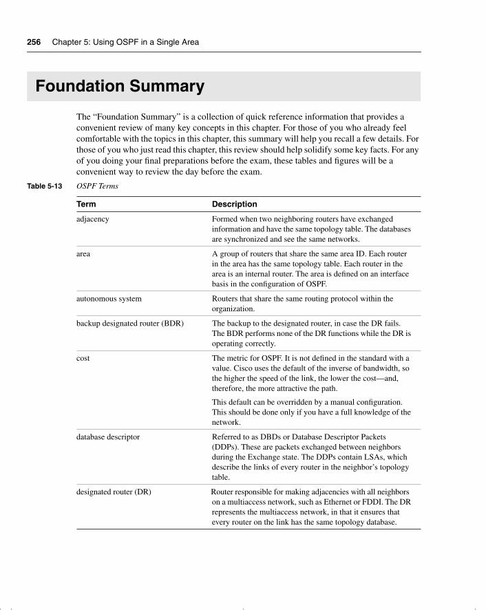
256 Chapter 5: Using OSPF in a Single Area
Foundation Summary
The “Foundation Summary” is a collection of quick reference information that provides a convenient review of many key concepts in this chapter. For those of you who already feel comfortable with the topics in this chapter, this summary will help you recall a few details. For those of you who just read this chapter, this review should help solidify some key facts. For any of you doing your final preparations before the exam, these tables and figures will be a convenient way to review the day before the exam.
Table 5-13 OSPF Terms
Term Description
adjacency Formed when two neighboring routers have exchanged information and have the same topology table. The databases are synchronized and see the same networks.
area A group of routers that share the same area ID. Each router in the area has the same topology table. Each router in the area is an internal router. The area is defined on an interface basis in the configuration of OSPF.
autonomous system Routers that share the same routing protocol within the organization.
backup designated router (BDR) The backup to the designated router, in case the DR fails. The BDR performs none of the DR functions while the DR is operating correctly.
cost The metric for OSPF. It is not defined in the standard with a value. Cisco uses the default of the inverse of bandwidth, so the higher the speed of the link, the lower the cost—and, therefore, the more attractive the path.
This default can be overridden by a manual configuration. This should be done only if you have a full knowledge of the network.
database descriptor Referred to as DBDs or Database Descriptor Packets (DDPs). These are packets exchanged between neighbors during the Exchange state. The DDPs contain LSAs, which describe the links of every router in the neighbor’s topology table.
designated router (DR) Router responsible for making adjacencies with all neighbors on a multiaccess network, such as Ethernet or FDDI. The DR represents the multiaccess network, in that it ensures that every router on the link has the same topology database.
chpt_01.book Page 256 Thursday, December 21, 2000 6:22 PM
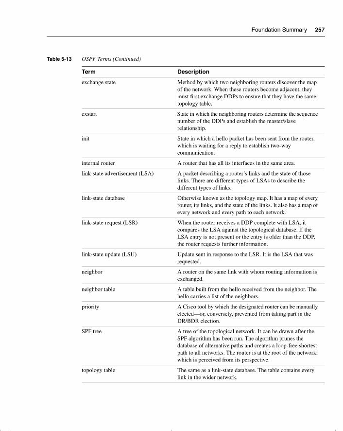
Foundation Summary 257
exchange state Method by which two neighboring routers discover the map of the network. When these routers become adjacent, they must first exchange DDPs to ensure that they have the same topology table.
exstart State in which the neighboring routers determine the sequence number of the DDPs and establish the master/slave relationship.
init State in which a hello packet has been sent from the router, which is waiting for a reply to establish two-way communication.
internal router A router that has all its interfaces in the same area.
link-state advertisement (LSA) A packet describing a router’s links and the state of those links. There are different types of LSAs to describe the different types of links.
link-state database Otherwise known as the topology map. It has a map of every router, its links, and the state of the links. It also has a map of every network and every path to each network.
link-state request (LSR) When the router receives a DDP complete with LSA, it compares the LSA against the topological database. If the LSA entry is not present or the entry is older than the DDP, the router requests further information.
link-state update (LSU) Update sent in response to the LSR. It is the LSA that was requested.
neighbor A router on the same link with whom routing information is exchanged.
neighbor table A table built from the hello received from the neighbor. The hello carries a list of the neighbors.
priority A Cisco tool by which the designated router can be manually elected—or, conversely, prevented from taking part in the DR/BDR election.
SPF tree A tree of the topological network. It can be drawn after the SPF algorithm has been run. The algorithm prunes the database of alternative paths and creates a loop-free shortest path to all networks. The router is at the root of the network, which is perceived from its perspective.
topology table The same as a link-state database. The table contains every link in the wider network.
Table 5-13 OSPF Terms (Continued)
Term Description
chpt_01.book Page 257 Thursday, December 21, 2000 6:22 PM
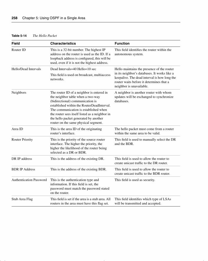
258 Chapter 5: Using OSPF in a Single Area
Table 5-14 The Hello Packet
Field Characteristics Function
Router ID This is a 32-bit number. The highest IP address on the router is used as the ID. If a loopback address is configured, this will be used, even if it is not the highest address.
This field identifies the router within the autonomous system.
Hello/Dead Intervals Dead Intervals=40 Hello=10 sec
This field is used on broadcast, multiaccess networks.
Hello maintains the presence of the router in its neighbor’s databases. It works like a keepalive. The dead interval is how long the router waits before it determines that a neighbor is unavailable.
Neighbors The router ID of a neighbor is entered in the neighbor table when a two-way (bidirectional) communication is established within the RouterDeadInterval. The communication is established when the router sees itself listed as a neighbor in the hello packet generated by another router on the same physical segment.
A neighbor is another router with whom updates will be exchanged to synchronize databases.
Area ID This is the area ID of the originating router’s interface.
The hello packet must come from a router within the same area to be valid.
Router Priority This is the priority of the source router interface. The higher the priority, the higher the likelihood of the router being selected as a DR or BDR.
This field is used to manually select the DR and the BDR.
DR IP address This is the address of the existing DR. This field is used to allow the router to create unicast traffic to the DR router.
BDR IP Address This is the address of the existing BDR. This field is used to allow the router to create unicast traffic to the BDR router.
Authentication Password This is the authentication type and information. If this field is set, the password must match the password stated on the router.
This field is used as security.
Stub Area Flag This field is set if the area is a stub area. All routers in the area must have this flag set.
This field identifies which type of LSAs will be transmitted and accepted.
chpt_01.book Page 258 Thursday, December 21, 2000 6:22 PM
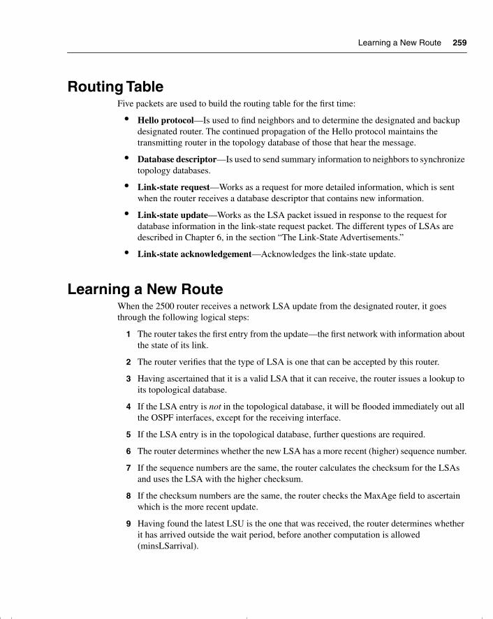
Learning a New Route 259
Routing TableFive packets are used to build the routing table for the first time:
• Hello protocol—Is used to find neighbors and to determine the designated and backup designated router. The continued propagation of the Hello protocol maintains the transmitting router in the topology database of those that hear the message.
• Database descriptor—Is used to send summary information to neighbors to synchronize topology databases.
• Link-state request—Works as a request for more detailed information, which is sent when the router receives a database descriptor that contains new information.
• Link-state update—Works as the LSA packet issued in response to the request for database information in the link-state request packet. The different types of LSAs are described in Chapter 6, in the section “The Link-State Advertisements.”
• Link-state acknowledgement—Acknowledges the link-state update.
Learning a New RouteWhen the 2500 router receives a network LSA update from the designated router, it goes through the following logical steps:
1 The router takes the first entry from the update—the first network with information about the state of its link.
2 The router verifies that the type of LSA is one that can be accepted by this router.
3 Having ascertained that it is a valid LSA that it can receive, the router issues a lookup to its topological database.
4 If the LSA entry is not in the topological database, it will be flooded immediately out all the OSPF interfaces, except for the receiving interface.
5 If the LSA entry is in the topological database, further questions are required.
6 The router determines whether the new LSA has a more recent (higher) sequence number.
7 If the sequence numbers are the same, the router calculates the checksum for the LSAs and uses the LSA with the higher checksum.
8 If the checksum numbers are the same, the router checks the MaxAge field to ascertain which is the more recent update.
9 Having found the latest LSU is the one that was received, the router determines whether it has arrived outside the wait period, before another computation is allowed (minsLSarrival).
chpt_01.book Page 259 Thursday, December 21, 2000 6:22 PM
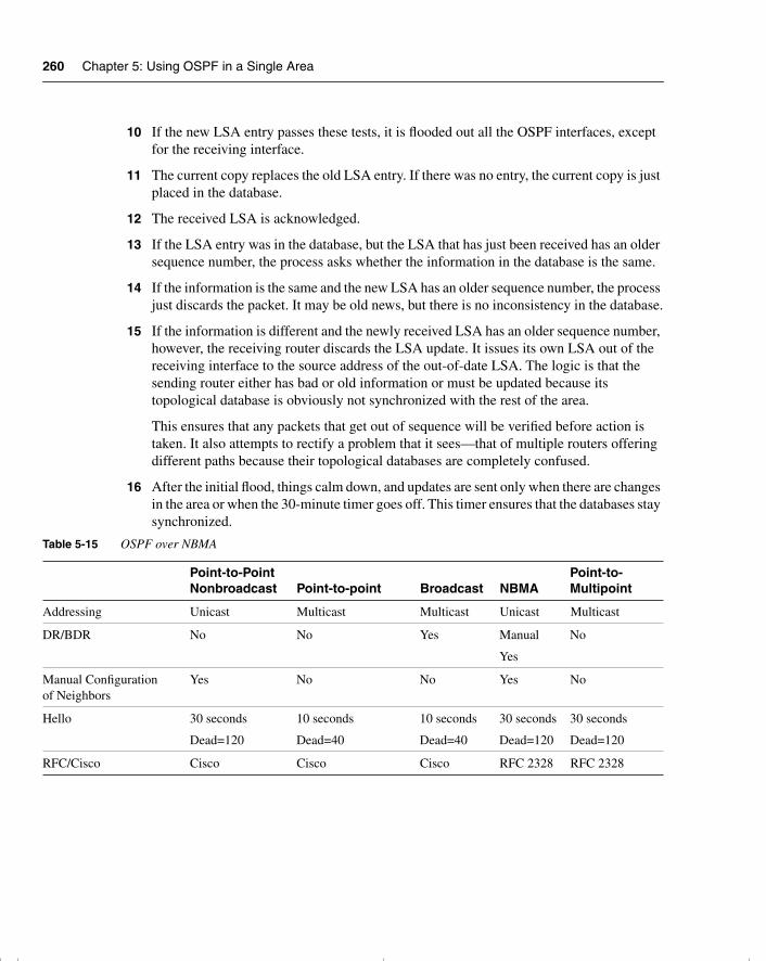
260 Chapter 5: Using OSPF in a Single Area
10 If the new LSA entry passes these tests, it is flooded out all the OSPF interfaces, except for the receiving interface.
11 The current copy replaces the old LSA entry. If there was no entry, the current copy is just placed in the database.
12 The received LSA is acknowledged.
13 If the LSA entry was in the database, but the LSA that has just been received has an older sequence number, the process asks whether the information in the database is the same.
14 If the information is the same and the new LSA has an older sequence number, the process just discards the packet. It may be old news, but there is no inconsistency in the database.
15 If the information is different and the newly received LSA has an older sequence number, however, the receiving router discards the LSA update. It issues its own LSA out of the receiving interface to the source address of the out-of-date LSA. The logic is that the sending router either has bad or old information or must be updated because its topological database is obviously not synchronized with the rest of the area.
This ensures that any packets that get out of sequence will be verified before action is taken. It also attempts to rectify a problem that it sees—that of multiple routers offering different paths because their topological databases are completely confused.
16 After the initial flood, things calm down, and updates are sent only when there are changes in the area or when the 30-minute timer goes off. This timer ensures that the databases stay synchronized.
Table 5-15 OSPF over NBMA
Point-to-Point Nonbroadcast Point-to-point Broadcast NBMA
Point-to-Multipoint
Addressing Unicast Multicast Multicast Unicast Multicast
DR/BDR No No Yes Manual
Yes
No
Manual Configuration of Neighbors
Yes No No Yes No
Hello 30 seconds
Dead=120
10 seconds
Dead=40
10 seconds
Dead=40
30 seconds
Dead=120
30 seconds
Dead=120
RFC/Cisco Cisco Cisco Cisco RFC 2328 RFC 2328
chpt_01.book Page 260 Thursday, December 21, 2000 6:22 PM
Command Summaries 261
Command SummariesThe following is a list of the commands explained in this chapter. This list is not intended to teach the use of the commands, but to remind the reader of the options available.
The commands in Table 5-16 are configuration commands.
Network Supported Star
Partial mesh
Star
Partial mesh, using subinterfaces
Full mesh Full mesh Star
Partial mesh
(seen as point-to-point)
Replicates Packets Yes Yes Yes Yes Yes
Number of Subnets 1 Many (1 per circuit) 1 1 1
Table 5-16 OSPF Configuration Command Summary
Command Description
router ospf process number Turns on the OSPF process and identifies it with a process ID.
network network number wildcard mask area area number
Identifies which networks—and, thus, interfaces—belong to which area.
interface loopback interface number
Creates the loopback interface that may now be used to create the router ID.
ip ospf cost cost Sets the cost or metric for the outgoing interface.
auto-cost reference-bandwidth reference-bandwidth
Allows the administrator to change the formula used to calculate the metric.
ip ospf priority number. Helps determine which router on a multiaccess network will be elected as the DR.
ip ospf network network option address mask
Identifies the type of network to the OSPF process, which will determine how the adjacencies are created.
neighbor ip-address [priority number ][poll-interval sec] [cost number]
States the neighbor, its address, and its capability to become the DR. This command also allows the configuration of cost and the timers on the interface.
Table 5-15 OSPF over NBMA (Continued)
Point-to-Point Nonbroadcast Point-to-point Broadcast NBMA
Point-to-Multipoint
chpt_01.book Page 261 Thursday, December 21, 2000 6:22 PM
262 Chapter 5: Using OSPF in a Single Area
The following commands are all executive commands to show the OSPF status and operation:
• show ip ospf—Shows the OSPF process and its details—for example, how many times the router has recalculated its routing table.
• show ospf database—Shows the contents of the topological database.
• show ip ospf interface—Gives information on how OSPF has been configured on each interface. Typing errors are easily seen with this command.
• show ip ospf neighbor—Displays all the information about the relationship that the router has with its neighbors—for example, the status of communication and whether it is initializing or transferring DDP packets.
• show ip protocols—Enables you to view the IP configuration on the router. It is useful because it shows not only the interfaces, but the configuration of the IP routing protocols as well.
• show ip route—Shows detailed information on the networks that the router is aware of and the preferred paths to those networks, as well as the next logical hop as the next step in the path (this command is covered in detail in Chapter 4).
Chapter GlossaryThis glossary provides an official Cisco definition for key words and terms introduced in this chapter. I have supplied my own definition for terms that the Cisco glossary does not contain. The words listed here are identified in the text by italics. A complete glossary, including all the chapter terms and additional terms, can be found in Appendix C, “Glossary.”
Dijkstra algorithm—A complex algorithm used by routers running link-state routing protocols to find the shortest path to the destination.
flood—A term that refers to network information. When it is flooded, it is sent to every network device in the domain.
fully adjacent—When the routing tables of the two neighbors are fully synchronized, with exactly the same view of the network.
loading state—State in which, if the receiving router requires more information during the process in which two routers are creating an adjacency, it will request that particular link in more detail using the link-state request packet (LSR). The LSR will prompt the master router to send the link-state update packet (LSU). This is the same as a link-state advertisement (LSA) used to flood the network with routing information. While the receiving router is awaiting the LSUs from its neighbor, it is in the loading state.
loopback interface—A virtual interface that does not exist physically. This characteristic makes it very powerful: If it does not exist, it can never go down.
chpt_01.book Page 262 Thursday, December 21, 2000 6:22 PM
Chapter Glossary 263
setup script—A question-and-answer dialogue that is offered by the Cisco router. If the router is booted without an existing configuration, it will ask you if you want to enter the setup script to create a basic configuration.
shortest path first (SPF)—The same as the Dijkstra algorithm, which is the algorithm used to find the shortest path.
two-way state—State during the process in which two routers are creating an adjacency. The new router sees its own router ID in the list of neighbors, and a neighbor relationship is established. This is the stage before routing information is exchanged.
chpt_01.book Page 263 Thursday, December 21, 2000 6:22 PM
264 Chapter 5: Using OSPF in a Single Area
Q&A
The following questions test your understanding of the topics covered in this chapter. The final questions in this section repeat of the opening “Do I Know This Already?” questions. These are repeated to enable you to test your progress. After you have answered the questions, find the answers in Appendix A. If you get an answer wrong, review the answer and ensure that you understand the reason for your mistake. If you are confused by the answer, refer to the appropriate text in the chapter to review the concepts.
1 What information is held in the topology table?
______________________________________________________________________
______________________________________________________________________
______________________________________________________________________
2 What command is used to manually determine which router on a LAN will become the DR?
______________________________________________________________________
______________________________________________________________________
______________________________________________________________________
3 What details are used to determine the metric of a route in OSPF by default on a Cisco router?
______________________________________________________________________
______________________________________________________________________
______________________________________________________________________
4 It is possible to have more than one OSPF process on a router—how would this be achieved?
______________________________________________________________________
______________________________________________________________________
______________________________________________________________________
5 Which RFC identifies the use of OSPF over an NBMA cloud?
______________________________________________________________________
______________________________________________________________________
______________________________________________________________________
chpt_01.book Page 264 Thursday, December 21, 2000 6:22 PM
Q&A 265
6 State the different types of packets used to build a routing table for the first time.
_______________________________________________________________________
_______________________________________________________________________
_______________________________________________________________________
7 In creating an adjacency, what is the exstart state?
_______________________________________________________________________
_______________________________________________________________________
_______________________________________________________________________
8 Explain the command ip ospf network non-broadcast.
_______________________________________________________________________
_______________________________________________________________________
_______________________________________________________________________
9 In which of the NBMA configuration choices is it necessary to manually state the neighbors? Why is this necessary?
_______________________________________________________________________
_______________________________________________________________________
_______________________________________________________________________
10 In a Frame Relay environment, which is fully meshed, which OSPF configurations might be chosen? Give reasons for your choice.
_______________________________________________________________________
_______________________________________________________________________
_______________________________________________________________________
11 How often by default does OSPF send out hello packets on a broadcast multiaccess link?
_______________________________________________________________________
_______________________________________________________________________
_______________________________________________________________________
12 What is a neighbor in OSPF?
_______________________________________________________________________
_______________________________________________________________________
_______________________________________________________________________
chpt_01.book Page 265 Thursday, December 21, 2000 6:22 PM
266 Chapter 5: Using OSPF in a Single Area
13 What is an adjacency in OSPF?
______________________________________________________________________
______________________________________________________________________
______________________________________________________________________
14 If the network is stable and sees no changes, how often will it send LSAs? Why are these updates sent out periodically?
______________________________________________________________________
______________________________________________________________________
______________________________________________________________________
15 If a router has an OSPF priority set to 0, what does this indicate?
______________________________________________________________________
______________________________________________________________________
______________________________________________________________________
16 What does NBMA stand for?
______________________________________________________________________
______________________________________________________________________
______________________________________________________________________
17 RFC 2328 describes the operation of OSPF in two modes across an NBMA cloud. What are they?
______________________________________________________________________
______________________________________________________________________
______________________________________________________________________
18 The Cisco solution point-to-point mode does not require the configuration of DR and BDR. Explain briefly why.
______________________________________________________________________
______________________________________________________________________
______________________________________________________________________
chpt_01.book Page 266 Thursday, December 21, 2000 6:22 PM
Q&A 267
19 The address 192.100.56.10 has been allocated to an interface on the router. This interface alone is to be included in the OSPF process. State the command that would start the process on this interface.
_______________________________________________________________________
_______________________________________________________________________
_______________________________________________________________________
20 What command would identify the designated router for your LAN?
_______________________________________________________________________
_______________________________________________________________________
_______________________________________________________________________
21 The metric used by OSPF is cost. How would you change the default setting on an interface?
_______________________________________________________________________
_______________________________________________________________________
_______________________________________________________________________
22 If the command ip ospf network non-broadcast is used, what additional statement is necessary?
_______________________________________________________________________
_______________________________________________________________________
_______________________________________________________________________
23 What command shows which router on a LAN is the BDR?
_______________________________________________________________________
_______________________________________________________________________
_______________________________________________________________________
24 Explain briefly what show ip ospf database will reveal.
_______________________________________________________________________
_______________________________________________________________________
_______________________________________________________________________
chpt_01.book Page 267 Thursday, December 21, 2000 6:22 PM
268 Chapter 5: Using OSPF in a Single Area
25 What command is used to show the state of adjacencies?
______________________________________________________________________
______________________________________________________________________
______________________________________________________________________
26 It is possible to have more than one OSPF process on a router. Which command would achieve this?
______________________________________________________________________
______________________________________________________________________
______________________________________________________________________
chpt_01.book Page 268 Thursday, December 21, 2000 6:22 PM
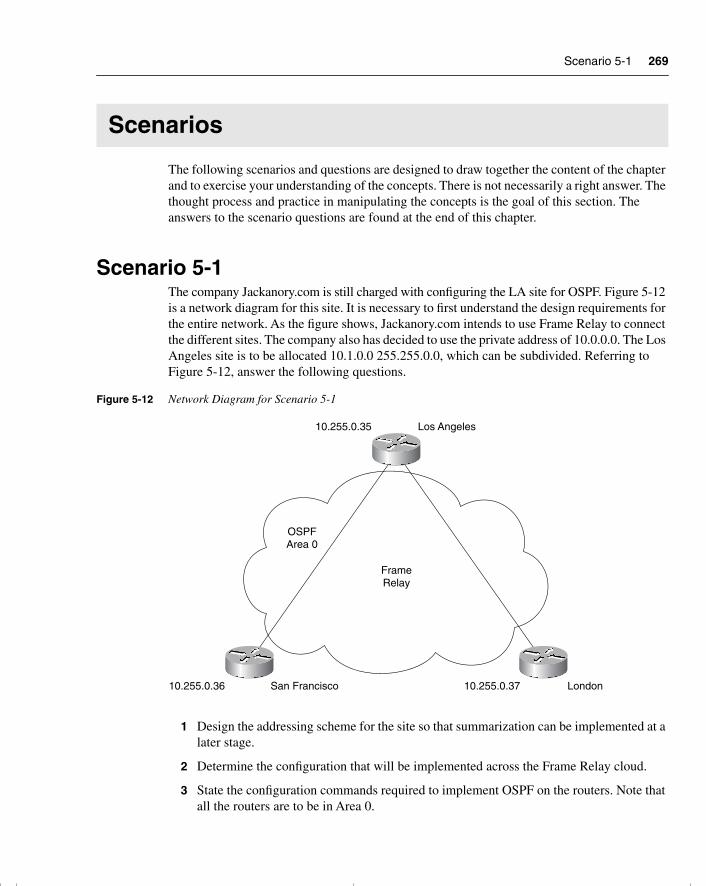
Scenario 5-1 269
Scenarios
The following scenarios and questions are designed to draw together the content of the chapter and to exercise your understanding of the concepts. There is not necessarily a right answer. The thought process and practice in manipulating the concepts is the goal of this section. The answers to the scenario questions are found at the end of this chapter.
Scenario 5-1The company Jackanory.com is still charged with configuring the LA site for OSPF. Figure 5-12 is a network diagram for this site. It is necessary to first understand the design requirements for the entire network. As the figure shows, Jackanory.com intends to use Frame Relay to connect the different sites. The company also has decided to use the private address of 10.0.0.0. The Los Angeles site is to be allocated 10.1.0.0 255.255.0.0, which can be subdivided. Referring to Figure 5-12, answer the following questions.
Figure 5-12 Network Diagram for Scenario 5-1
1 Design the addressing scheme for the site so that summarization can be implemented at a later stage.
2 Determine the configuration that will be implemented across the Frame Relay cloud.
3 State the configuration commands required to implement OSPF on the routers. Note that all the routers are to be in Area 0.
Los Angeles10.255.0.35
San Francisco10.255.0.36 London10.255.0.37
FrameRelay
OSPFArea 0
chpt_01.book Page 269 Thursday, December 21, 2000 6:22 PM
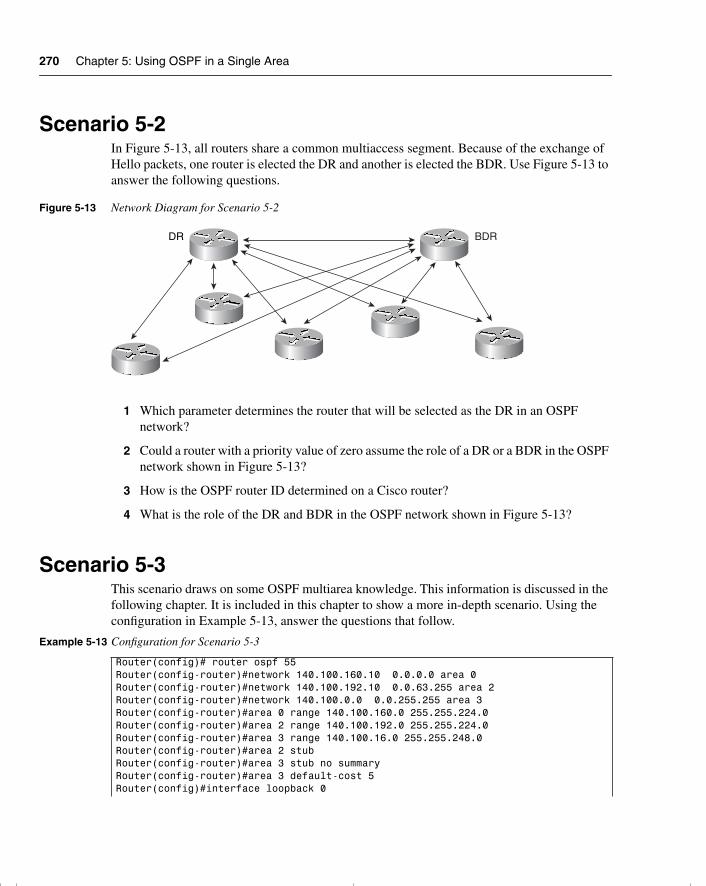
270 Chapter 5: Using OSPF in a Single Area
Scenario 5-2In Figure 5-13, all routers share a common multiaccess segment. Because of the exchange of Hello packets, one router is elected the DR and another is elected the BDR. Use Figure 5-13 to answer the following questions.
Figure 5-13 Network Diagram for Scenario 5-2
1 Which parameter determines the router that will be selected as the DR in an OSPF network?
2 Could a router with a priority value of zero assume the role of a DR or a BDR in the OSPF network shown in Figure 5-13?
3 How is the OSPF router ID determined on a Cisco router?
4 What is the role of the DR and BDR in the OSPF network shown in Figure 5-13?
Scenario 5-3This scenario draws on some OSPF multiarea knowledge. This information is discussed in the following chapter. It is included in this chapter to show a more in-depth scenario. Using the configuration in Example 5-13, answer the questions that follow.
Example 5-13 Configuration for Scenario 5-3
Router(config)# router ospf 55Router(config-router)#network 140.100.160.10 0.0.0.0 area 0Router(config-router)#network 140.100.192.10 0.0.63.255 area 2Router(config-router)#network 140.100.0.0 0.0.255.255 area 3Router(config-router)#area 0 range 140.100.160.0 255.255.224.0Router(config-router)#area 2 range 140.100.192.0 255.255.224.0Router(config-router)#area 3 range 140.100.16.0 255.255.248.0Router(config-router)#area 2 stub Router(config-router)#area 3 stub no summaryRouter(config-router)#area 3 default-cost 5Router(config)#interface loopback 0
DR BDR
chpt_01.book Page 270 Thursday, December 21, 2000 6:22 PM
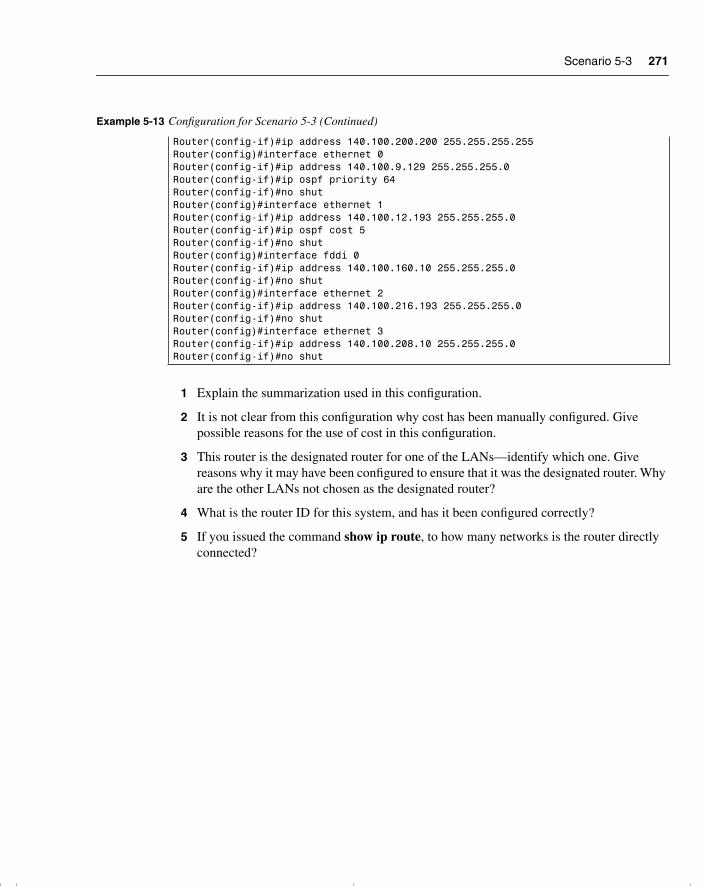
Scenario 5-3 271
1 Explain the summarization used in this configuration.
2 It is not clear from this configuration why cost has been manually configured. Give possible reasons for the use of cost in this configuration.
3 This router is the designated router for one of the LANs—identify which one. Give reasons why it may have been configured to ensure that it was the designated router. Why are the other LANs not chosen as the designated router?
4 What is the router ID for this system, and has it been configured correctly?
5 If you issued the command show ip route, to how many networks is the router directly connected?
Router(config-if)#ip address 140.100.200.200 255.255.255.255 Router(config)#interface ethernet 0Router(config-if)#ip address 140.100.9.129 255.255.255.0Router(config-if)#ip ospf priority 64Router(config-if)#no shutRouter(config)#interface ethernet 1Router(config-if)#ip address 140.100.12.193 255.255.255.0Router(config-if)#ip ospf cost 5Router(config-if)#no shutRouter(config)#interface fddi 0Router(config-if)#ip address 140.100.160.10 255.255.255.0Router(config-if)#no shutRouter(config)#interface ethernet 2Router(config-if)#ip address 140.100.216.193 255.255.255.0Router(config-if)#no shutRouter(config)#interface ethernet 3Router(config-if)#ip address 140.100.208.10 255.255.255.0Router(config-if)#no shut
Example 5-13 Configuration for Scenario 5-3 (Continued)
chpt_01.book Page 271 Thursday, December 21, 2000 6:22 PM
272 Chapter 5: Using OSPF in a Single Area
Scenario Answers
The answers are in bold. The answers provided in this section are not necessarily the only possible answers to the questions. The questions are designed to test your knowledge and to give practical exercise in certain key areas. This section is intended to test and exercise skills and concepts detailed in the body of this chapter.
If your answer is different, ask yourself whether it follows the tenets explained in the answers provided. Your answer is correct not if it matches the solution provided in the book, but rather if it has included the principles of design laid out in the chapter.
In this way, the testing provided in these scenarios is deeper: It examines not only your knowledge, but also your understanding and ability to apply that knowledge to problems.
If you do not get the correct answer, refer back to the text and review the subject tested. Be certain to also review your notes on the question to ensure that you understand the principles of the subject.
Scenario 5-1 Answers1 Design the addressing scheme for the site so that summarization can be implemented at a
later stage.
An addressing scheme for the Los Angeles site could be as shown in Figure 5-14.
2 Determine the configuration that will be implemented across the Frame Relay cloud.
The Frame Relay configuration is a hub-and-spoke topology. Because Los Angeles is the central hub of the company, it is logical that it is also the network hub.
The configuration in Frame Relay would therefore be a point-to-multipoint one. This avoids the DR/BDR election process because it treats all the PVC links as a collection of point-to-point links, therefore removing the need for the DR/BDR. This is a good solution if the three different companies have a multivendor environment because it conforms to the RFC standards.
chpt_01.book Page 272 Thursday, December 21, 2000 6:22 PM
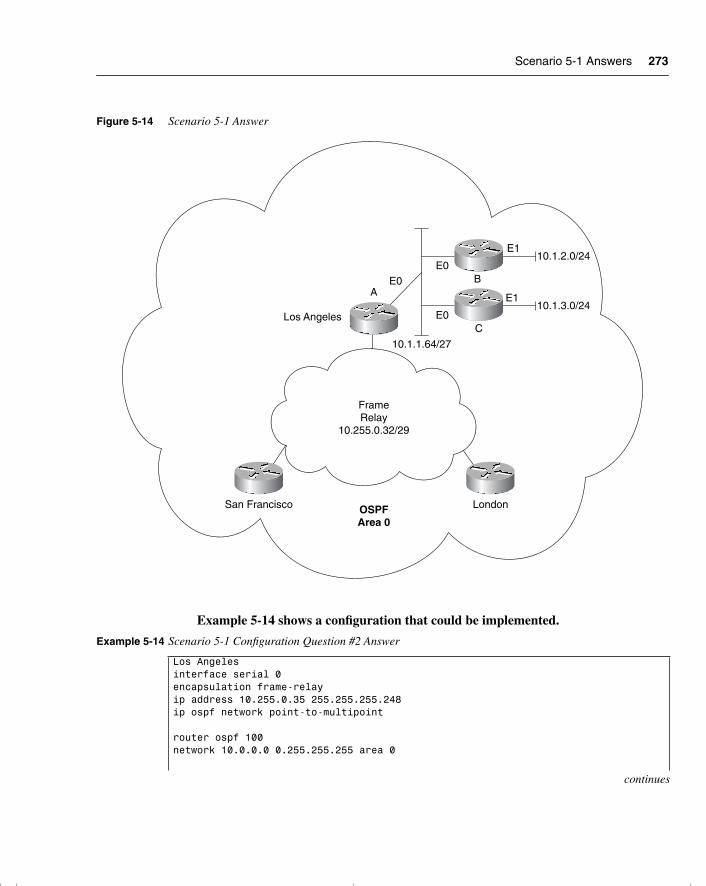
Scenario 5-1 Answers 273
Figure 5-14 Scenario 5-1 Answer
Example 5-14 shows a configuration that could be implemented.
Example 5-14 Scenario 5-1 Configuration Question #2 Answer
Los Angelesinterface serial 0encapsulation frame-relayip address 10.255.0.35 255.255.255.248ip ospf network point-to-multipoint
router ospf 100network 10.0.0.0 0.255.255.255 area 0
continues
Los Angeles
San Francisco LondonOSPFArea 0
FrameRelay
10.255.0.32/29
AE0
E0B
E1
E0C
E1
10.1.1.64/27
10.1.2.0/24
10.1.3.0/24
chpt_01.book Page 273 Thursday, December 21, 2000 6:22 PM
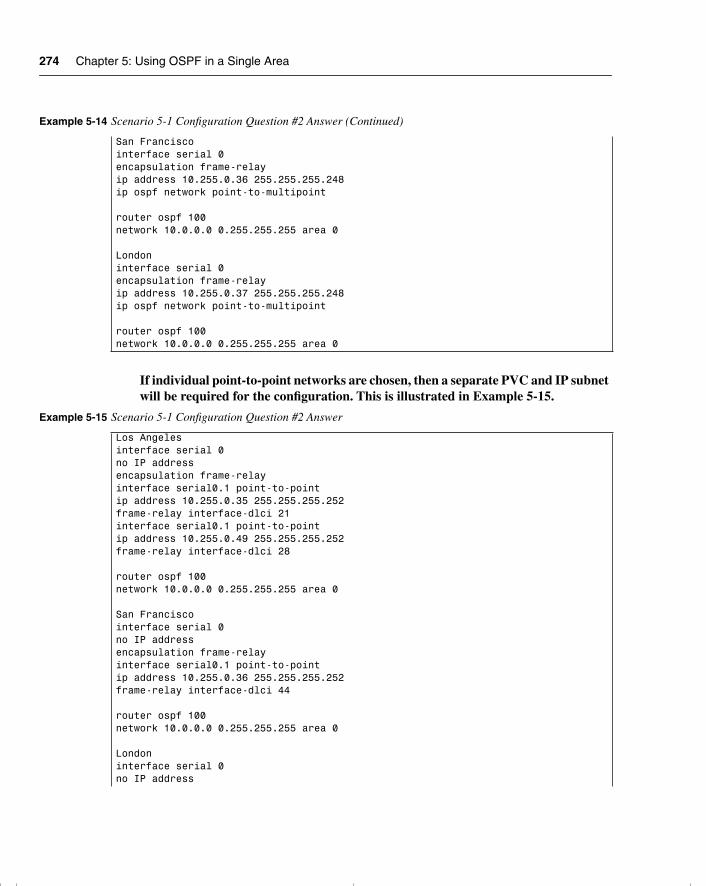
274 Chapter 5: Using OSPF in a Single Area
If individual point-to-point networks are chosen, then a separate PVC and IP subnet will be required for the configuration. This is illustrated in Example 5-15.
San Franciscointerface serial 0encapsulation frame-relayip address 10.255.0.36 255.255.255.248ip ospf network point-to-multipoint
router ospf 100network 10.0.0.0 0.255.255.255 area 0
Londoninterface serial 0encapsulation frame-relayip address 10.255.0.37 255.255.255.248ip ospf network point-to-multipoint
router ospf 100network 10.0.0.0 0.255.255.255 area 0
Example 5-15 Scenario 5-1 Configuration Question #2 Answer
Los Angelesinterface serial 0no IP addressencapsulation frame-relayinterface serial0.1 point-to-pointip address 10.255.0.35 255.255.255.252frame-relay interface-dlci 21interface serial0.1 point-to-pointip address 10.255.0.49 255.255.255.252frame-relay interface-dlci 28
router ospf 100network 10.0.0.0 0.255.255.255 area 0
San Franciscointerface serial 0no IP addressencapsulation frame-relayinterface serial0.1 point-to-pointip address 10.255.0.36 255.255.255.252frame-relay interface-dlci 44
router ospf 100network 10.0.0.0 0.255.255.255 area 0
Londoninterface serial 0no IP address
Example 5-14 Scenario 5-1 Configuration Question #2 Answer (Continued)
chpt_01.book Page 274 Thursday, December 21, 2000 6:22 PM
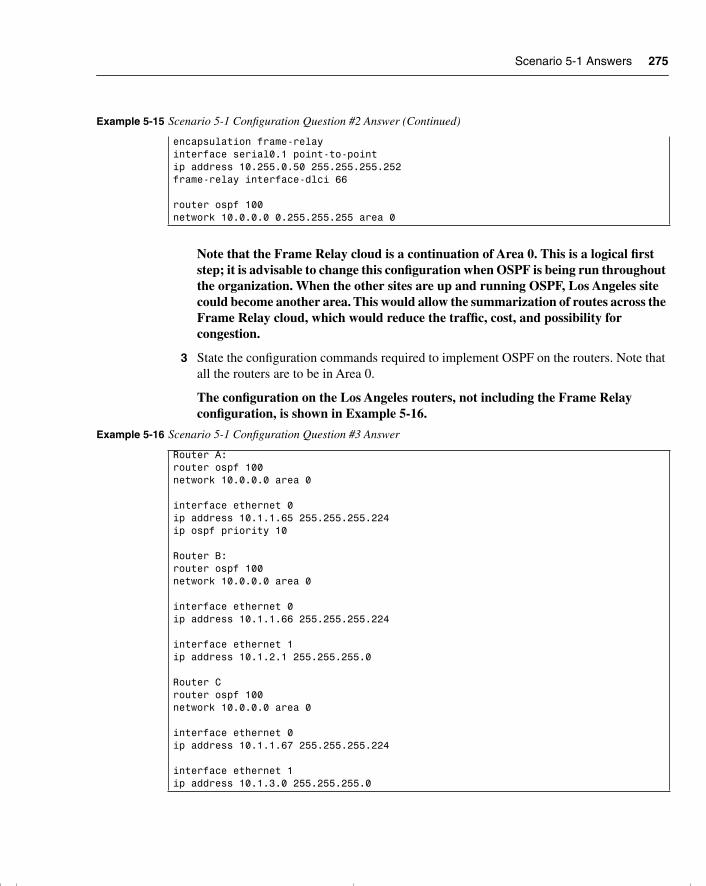
Scenario 5-1 Answers 275
Note that the Frame Relay cloud is a continuation of Area 0. This is a logical first step; it is advisable to change this configuration when OSPF is being run throughout the organization. When the other sites are up and running OSPF, Los Angeles site could become another area. This would allow the summarization of routes across the Frame Relay cloud, which would reduce the traffic, cost, and possibility for congestion.
3 State the configuration commands required to implement OSPF on the routers. Note that all the routers are to be in Area 0.
The configuration on the Los Angeles routers, not including the Frame Relay configuration, is shown in Example 5-16.
encapsulation frame-relayinterface serial0.1 point-to-pointip address 10.255.0.50 255.255.255.252frame-relay interface-dlci 66
router ospf 100network 10.0.0.0 0.255.255.255 area 0
Example 5-16 Scenario 5-1 Configuration Question #3 Answer
Router A:router ospf 100network 10.0.0.0 area 0
interface ethernet 0ip address 10.1.1.65 255.255.255.224ip ospf priority 10
Router B:router ospf 100network 10.0.0.0 area 0
interface ethernet 0ip address 10.1.1.66 255.255.255.224
interface ethernet 1ip address 10.1.2.1 255.255.255.0
Router Crouter ospf 100network 10.0.0.0 area 0
interface ethernet 0ip address 10.1.1.67 255.255.255.224
interface ethernet 1ip address 10.1.3.0 255.255.255.0
Example 5-15 Scenario 5-1 Configuration Question #2 Answer (Continued)
chpt_01.book Page 275 Thursday, December 21, 2000 6:22 PM
276 Chapter 5: Using OSPF in a Single Area
Note that Router A has been given a priority of 10, ensuring that it becomes the DR. Although this is not essential, it is a clear configuration and is advisable because this router is a larger system and very reliable. For the same reasons, it is also considered good system management to define the priority for the BDR.
Scenario 5-2 Answers1 Which parameter determines the router that will be selected as the DR in an OSPF
network?
The router with the highest OSPF priority on a segment will become the DR for that segment. The default for the interface OSPF priority is 1. If multiple routers have the same priority, the router with the highest RID will be selected as the DR.
2 Could a router with a priority value of zero assume the role of a DR or BDR in the OSPF network shown in Figure 5-13?
No. A priority value of zero indicates an interface is not to be elected as a DR or BDR. The state of the interface with priority zero will be DROTHER.
3 How is the OSPF router ID determined on a Cisco router?
The OSPF router ID is the highest IP address on the box, or the highest loopback address, if one exists.
4 What is the role of the DR and the BDR in the OSPF network shown in Figure 5-13?
Instead of each router exchanging updates with every other router on the segment, every router will exchange the information with the DR and the BDR. The DR and the BDR will relay the information to everybody else. In mathematical terms, this cuts the information exchange from O(n × n) to O(n), where n is the number of routers on a multiaccess segment.
Scenario 5-3 Answers1 Explain the summarization used in this configuration.
The summarization used in Scenario 5-3 will be broken out by area and is demonstrated in Table 5-17.
chpt_01.book Page 276 Thursday, December 21, 2000 6:22 PM
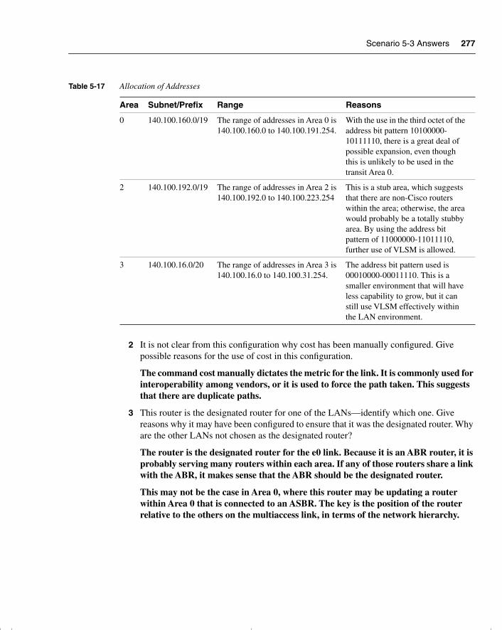
Scenario 5-3 Answers 277
2 It is not clear from this configuration why cost has been manually configured. Give possible reasons for the use of cost in this configuration.
The command cost manually dictates the metric for the link. It is commonly used for interoperability among vendors, or it is used to force the path taken. This suggests that there are duplicate paths.
3 This router is the designated router for one of the LANs—identify which one. Give reasons why it may have been configured to ensure that it was the designated router. Why are the other LANs not chosen as the designated router?
The router is the designated router for the e0 link. Because it is an ABR router, it is probably serving many routers within each area. If any of those routers share a link with the ABR, it makes sense that the ABR should be the designated router.
This may not be the case in Area 0, where this router may be updating a router within Area 0 that is connected to an ASBR. The key is the position of the router relative to the others on the multiaccess link, in terms of the network hierarchy.
Table 5-17 Allocation of Addresses
Area Subnet/Prefix Range Reasons
0 140.100.160.0/19 The range of addresses in Area 0 is140.100.160.0 to 140.100.191.254.
With the use in the third octet of the address bit pattern 10100000-10111110, there is a great deal of possible expansion, even though this is unlikely to be used in the transit Area 0.
2 140.100.192.0/19 The range of addresses in Area 2 is140.100.192.0 to 140.100.223.254
This is a stub area, which suggests that there are non-Cisco routers within the area; otherwise, the area would probably be a totally stubby area. By using the address bit pattern of 11000000-11011110, further use of VLSM is allowed.
3 140.100.16.0/20 The range of addresses in Area 3 is140.100.16.0 to 140.100.31.254.
The address bit pattern used is 00010000-00011110. This is a smaller environment that will have less capability to grow, but it can still use VLSM effectively within the LAN environment.
chpt_01.book Page 277 Thursday, December 21, 2000 6:22 PM
278 Chapter 5: Using OSPF in a Single Area
4 What is the router ID for this system, and has it been configured correctly?
The router ID for this router is 140.100.200.200. This is taken from the loopback interface that was configured. It is configured correctly because OSPF supports host routing, and the 255.255.255.255 mask is in fact used in a loopback configuration to save address space.
5 If you issued the command show ip route, to how many networks is the router directly connected?
It is directly connected to five interfaces—and, therefore, five networks—and one host. The host is the loopback interface with a 32-bit mask.
chpt_01.book Page 278 Thursday, December 21, 2000 6:22 PM

chpt_01.book Page 279 Thursday, December 21, 2000 6:22 PM
This chapter covers the following topics that you will need to master to pass the CCNP/CCDP Routing exam:
• The issues with interconnecting multiple areas.
• The differences between the possible types of areas, routers, and LSAs.
• How OSPF operates across multiple areas using NBMA.
• How OSPF supports the use of VLSM and summarization.
• The Cisco defaults in OSPF, the Cisco commands for implementing OSPF for multiple areas, and Cisco commands for reviewing the configuration.
chpt_01.book Page 280 Thursday, December 21, 2000 6:22 PM
C H A P T E R 6Using OSPF Across Multiple Areas
The topics in this chapter detail the routing protocol OSPF across multiple areas. This chapter assumes your knowledge of the previous chapter, which dealt with OSPF concepts and its configuration in a single area. This chapter builds on this understanding and explains
how OSPF works within a large multiarea network. Each of these chapters covers two major sections. The first deals theoretically with how the protocol works. The second covers how to implement and manage an OSPF network. This chapter introduces OSPF areas and explains the operation of the protocol across those areas. Both the network communication that the protocol uses and its configuration are explained in this chapter.
The topics in this chapter will directly reflect questions on the exam. OSPF is the industry-standard interior routing protocol designed for use in large networks. Therefore, it is an obligatory subject in an exam on IP routing protocols. Nine percent of the BSCN course material is devoted to interconnecting multiple OSPF areas, and you can expect approximately four to five questions on the Routing exam to be directly related to this subject.
How to Best Use This ChapterBy taking the following steps, you can make better use of your study time:
• Keep your notes and the answers for all your work with this book in one place, for easy reference.
• When you take a quiz, write down your answers. Studies show that retention significantly increases by writing down facts and concepts, even if you never look at the information again.
• Use the diagram in Figure 6-1 to guide you to the next step.
chpt_01.book Page 281 Thursday, December 21, 2000 6:22 PM
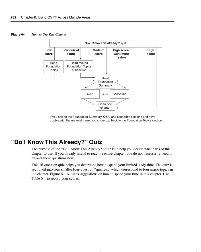
282 Chapter 6: Using OSPF Across Multiple Areas
Figure 6-1 How to Use This Chapter
“Do I Know This Already?” QuizThe purpose of the “Do I Know This Already?” quiz is to help you decide what parts of this chapter to use. If you already intend to read the entire chapter, you do not necessarily need to answer these questions now.
This 16-question quiz helps you determine how to spend your limited study time. The quiz is sectioned into four smaller four-question “quizlets,” which correspond to four major topics in the chapter. Figure 6-1 outlines suggestions on how to spend your time in this chapter. Use Table 6-1 to record your scores.
Lowscore
Low quizletscore
Mediumscore
High score,want more
review
Highscore
"Do I Know This Already?" quiz
ReadFoundation
Topics
Read relatedFoundation Topics
subsection
ReadFoundationSummary
Q&A Scenarios
Go to nextchapter
If you skip to the Foundation Summary, Q&A, and scenarios sections and havetrouble with the material there, you should go back to the Foundation Topics section.
chpt_01.book Page 282 Thursday, December 21, 2000 6:22 PM
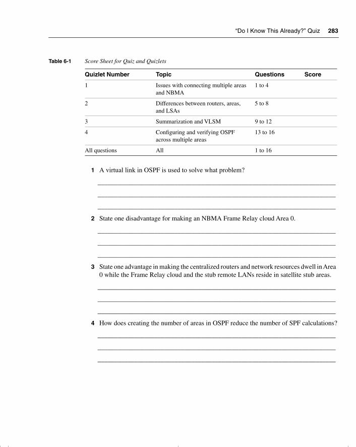
“Do I Know This Already?” Quiz 283
1 A virtual link in OSPF is used to solve what problem?
_______________________________________________________________________
_______________________________________________________________________
_______________________________________________________________________
2 State one disadvantage for making an NBMA Frame Relay cloud Area 0.
_______________________________________________________________________
_______________________________________________________________________
_______________________________________________________________________
3 State one advantage in making the centralized routers and network resources dwell in Area 0 while the Frame Relay cloud and the stub remote LANs reside in satellite stub areas.
_______________________________________________________________________
_______________________________________________________________________
_______________________________________________________________________
4 How does creating the number of areas in OSPF reduce the number of SPF calculations?
_______________________________________________________________________
_______________________________________________________________________
_______________________________________________________________________
Table 6-1 Score Sheet for Quiz and Quizlets
Quizlet Number Topic Questions Score
1 Issues with connecting multiple areas and NBMA
1 to 4
2 Differences between routers, areas, and LSAs
5 to 8
3 Summarization and VLSM 9 to 12
4 Configuring and verifying OSPF across multiple areas
13 to 16
All questions All 1 to 16
chpt_01.book Page 283 Thursday, December 21, 2000 6:22 PM
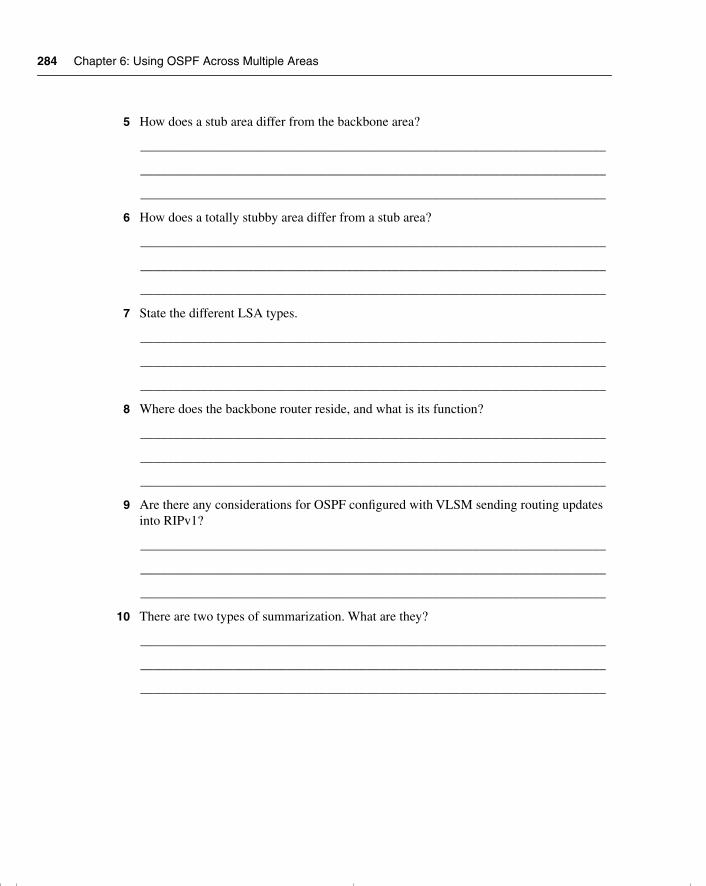
284 Chapter 6: Using OSPF Across Multiple Areas
5 How does a stub area differ from the backbone area?
______________________________________________________________________
______________________________________________________________________
______________________________________________________________________
6 How does a totally stubby area differ from a stub area?
______________________________________________________________________
______________________________________________________________________
______________________________________________________________________
7 State the different LSA types.
______________________________________________________________________
______________________________________________________________________
______________________________________________________________________
8 Where does the backbone router reside, and what is its function?
______________________________________________________________________
______________________________________________________________________
______________________________________________________________________
9 Are there any considerations for OSPF configured with VLSM sending routing updates into RIPv1?
______________________________________________________________________
______________________________________________________________________
______________________________________________________________________
10 There are two types of summarization. What are they?
______________________________________________________________________
______________________________________________________________________
______________________________________________________________________
chpt_01.book Page 284 Thursday, December 21, 2000 6:22 PM
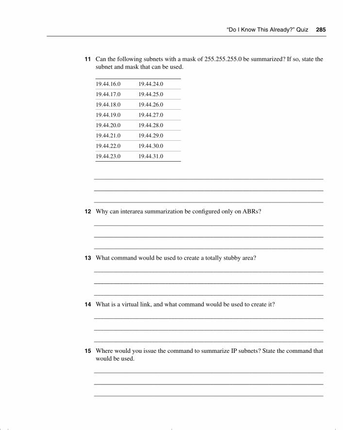
“Do I Know This Already?” Quiz 285
11 Can the following subnets with a mask of 255.255.255.0 be summarized? If so, state the subnet and mask that can be used.
_______________________________________________________________________
_______________________________________________________________________
_______________________________________________________________________
12 Why can interarea summarization be configured only on ABRs?
_______________________________________________________________________
_______________________________________________________________________
_______________________________________________________________________
13 What command would be used to create a totally stubby area?
_______________________________________________________________________
_______________________________________________________________________
_______________________________________________________________________
14 What is a virtual link, and what command would be used to create it?
_______________________________________________________________________
_______________________________________________________________________
_______________________________________________________________________
15 Where would you issue the command to summarize IP subnets? State the command that would be used.
_______________________________________________________________________
_______________________________________________________________________
_______________________________________________________________________
19.44.16.0 19.44.24.0
19.44.17.0 19.44.25.0
19.44.18.0 19.44.26.0
19.44.19.0 19.44.27.0
19.44.20.0 19.44.28.0
19.44.21.0 19.44.29.0
19.44.22.0 19.44.30.0
19.44.23.0 19.44.31.0
chpt_01.book Page 285 Thursday, December 21, 2000 6:22 PM
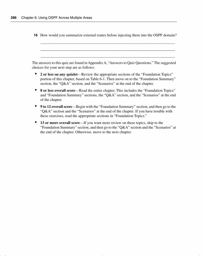
286 Chapter 6: Using OSPF Across Multiple Areas
16 How would you summarize external routes before injecting them into the OSPF domain?
______________________________________________________________________
______________________________________________________________________
______________________________________________________________________
The answers to this quiz are found in Appendix A, “Answers to Quiz Questions.” The suggested choices for your next step are as follows:
• 2 or less on any quizlet—Review the appropriate sections of the “Foundation Topics” portion of this chapter, based on Table 6-1. Then move on to the “Foundation Summary” section, the “Q&A” section, and the “Scenarios” at the end of the chapter.
• 8 or less overall score—Read the entire chapter. This includes the “Foundation Topics” and “Foundation Summary” sections, the “Q&A” section, and the “Scenarios” at the end of the chapter.
• 9 to 12 overall score—Begin with the “Foundation Summary” section, and then go to the “Q&A” section and the “Scenarios” at the end of the chapter. If you have trouble with these exercises, read the appropriate sections in “Foundation Topics.”
• 13 or more overall score—If you want more review on these topics, skip to the “Foundation Summary” section, and then go to the “Q&A” section and the “Scenarios” at the end of the chapter. Otherwise, move to the next chapter.
chpt_01.book Page 286 Thursday, December 21, 2000 6:22 PM
OSPF in a Multiple Area Network 287
Foundation Topics
The following section examines the implications of using OSPF in a larger network.
OSPF in a Multiple Area NetworkThe first consideration must be why multiple areas are needed. There is a lot of noise about multiple areas in OSPF, and indeed it is one of the main distinguishing features between the distance vector protocols and the link-state OSPF.
Case StudyReturning to the company Jackanory.com, you will recall that in the previous chapter, Jackanory.com was acquired along with some other companies. The company is still operating intact but must communicate with the other companies and with the holding company that purchased it. Most of the communication occurs with the parent company, although there is occasional work done on a project basis with the other companies. The parent company needs to be capable of communicating with all the small companies that it holds.
The infrastructure within the companies is to stay the same, but a Frame Relay network has been created to connect the sites. OSPF has been implemented internally at Jackanory.com, and it is working well. Now it is necessary to implement OSPF at the other sites and to have a complete understanding of all the networks available.
The network administrators have been charged with making this happen. There is more to be done than simply typing in the appropriate commands, of course. The administrators need to understand and decide on several things. These include whether summarization is possible and desired for the Frame Relay design, what design is appropriate for the OSPF areas, and whether any of the areas should be stub, totally stubby, or not so stubby areas. To make these decisions, the administrators must understand the OSPF operation over multiple areas. This chapter addresses these subjects and then, in the final section, shows the configuration options and requirements.
Why Multiple Areas?An area is a logical grouping of routers that are running OSPF with identical topological databases. It is a subdivision of the greater OSPF domain. The creation of multiple areas solves the problem of a large network outgrowing its capacity to communicate the details of the network to the routing devices charged with maintaining control and connectivity throughout the network.
chpt_01.book Page 287 Thursday, December 21, 2000 6:22 PM
288 Chapter 6: Using OSPF Across Multiple Areas
The division of the AS into areas allows routers in each area to maintain their own topological databases. This limits the size of the topological databases, and summary and external links ensure connectivity between areas and networks outside the AS.
How to Determine Area BoundariesAlthough there is an obvious need for the multiple areas, the practical question of how this is implemented arises. There are two approaches. The first approach is to grow a single area until it becomes unmanageable. The second approach is to design the network with multiple areas, which are very small, in the expectation that the networks will grow to fit comfortably into their areas.
Both approaches are valid. The first approach requires less initial work and configuration. Great care should be put into the design of the network, however, because this may cause problems in the future, particularly in addressing.
In practice, many companies convert their networks into OSPF from a distance vector routing protocol when they realize that they have outgrown the existing routing protocol. This allows the planned implementation of the second approach.
Now consider the implications of implementing the first approach to OSPF—that of configuring one area and adding others as needed. By looking at the issues, you can learn many things beyond just how to create multiple areas.
Problems with OSPF in a Single AreaTo understand the true benefits of multiple areas, consider why someone might decide to create multiple areas from one area.
The following symptoms that you will observe on the network provide a clue that a single area is becoming overpowered:
• The frequency of the SPF algorithm being run will increase. The larger the network, the greater the probability of a network change and, thus, a recalculation of the entire area. Each recalculation will also take longer.
• The routing table will become extremely large. The routing table is not sent out wholesale as in a distance vector routing protocol; however, the greater the size of the table, the longer each lookup becomes. The memory requirements on the router also increase.
• The topological database will increase in size and will eventually become unmanageable for the same reasons. The topology table is exchanged between adjacent routers at least every 30 minutes.
chpt_01.book Page 288 Thursday, December 21, 2000 6:22 PM
OSPF Areas 289
• As the various databases increase in size and the calculations become increasingly frequent, the CPU utilization will increase as the available memory decreases. This will make the network response time very sluggish (not because of congestion on the line, but because of congestion within the router itself). It can also cause congestion on the link.
TIP To check the CPU utilization on the router, use the show cpu process command. To check the memory utilization, issue the show memory command.
OSPF AreasNow that you understand why the size of the areas should be controlled, it is important to consider the design issues for the different areas, including the technology that underpins them and their communication (both within and between the areas).
OSPF Within an AreaOne of the main strengths of OSPF is its capability to scale and to support large networks. It achieves this by creating areas from groups of subnets. The area is seen internally almost as if it is a small organization or entity on its own. It communicates with the other areas, exchanging routing information; this exchange is kept to a minimum, however, allowing only that which is required for connectivity. All computation is kept within the area.
In this way, a router is not overwhelmed by the entirety of the organization’s network. This is crucial because the nature of a link-state routing protocol is more CPU- and memory-intensive.
Router TypesGiven the hierarchical nature of the OSPF network, you will see routers operating within an area, routers connecting areas, and routers connecting the organization or autonomous system to the outside world. Each of these routers will have a different set of responsibilities, depending on their position and functionality within the OSPF hierarchical design.
The following list identifies the different OSPF routers:
• Internal router—Within an area, the functionality of the router is straightforward. It is responsible for maintaining a current and accurate database of every subnet within the area. It is also responsible for forwarding data to other networks by the shortest path. Flooding of routing updates is confined to the area. All interfaces on this router are within the same area.
chpt_01.book Page 289 Thursday, December 21, 2000 6:22 PM
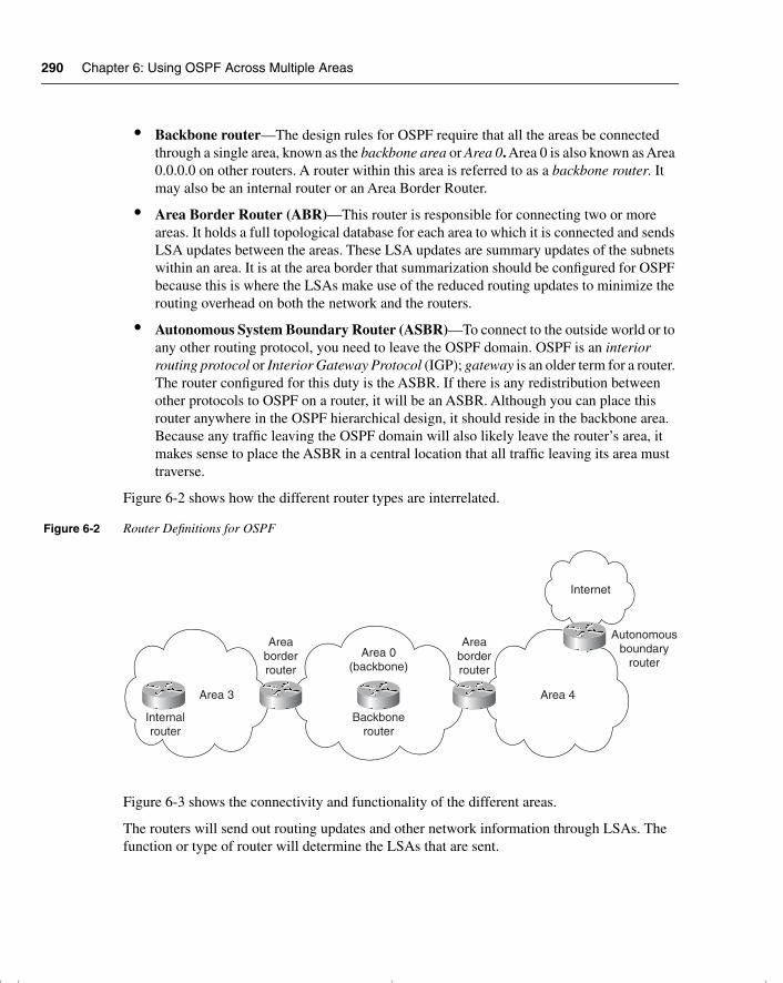
290 Chapter 6: Using OSPF Across Multiple Areas
• Backbone router—The design rules for OSPF require that all the areas be connected through a single area, known as the backbone area or Area 0. Area 0 is also known as Area 0.0.0.0 on other routers. A router within this area is referred to as a backbone router. It may also be an internal router or an Area Border Router.
• Area Border Router (ABR)—This router is responsible for connecting two or more areas. It holds a full topological database for each area to which it is connected and sends LSA updates between the areas. These LSA updates are summary updates of the subnets within an area. It is at the area border that summarization should be configured for OSPF because this is where the LSAs make use of the reduced routing updates to minimize the routing overhead on both the network and the routers.
• Autonomous System Boundary Router (ASBR)—To connect to the outside world or to any other routing protocol, you need to leave the OSPF domain. OSPF is an interior routing protocol or Interior Gateway Protocol (IGP); gateway is an older term for a router. The router configured for this duty is the ASBR. If there is any redistribution between other protocols to OSPF on a router, it will be an ASBR. Although you can place this router anywhere in the OSPF hierarchical design, it should reside in the backbone area. Because any traffic leaving the OSPF domain will also likely leave the router’s area, it makes sense to place the ASBR in a central location that all traffic leaving its area must traverse.
Figure 6-2 shows how the different router types are interrelated.
Figure 6-2 Router Definitions for OSPF
Figure 6-3 shows the connectivity and functionality of the different areas.
The routers will send out routing updates and other network information through LSAs. The function or type of router will determine the LSAs that are sent.
Area 3
Areaborderrouter
Areaborderrouter
Area 0(backbone)
Backbonerouter
Internalrouter
Internet
Autonomousboundary
router
Area 4
chpt_01.book Page 290 Thursday, December 21, 2000 6:22 PM
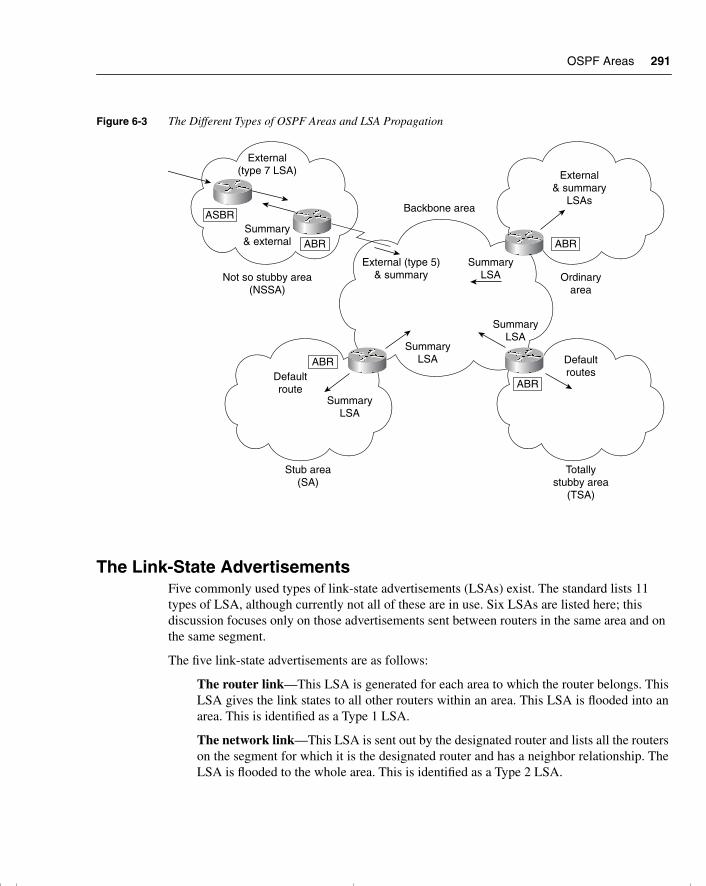
OSPF Areas 291
Figure 6-3 The Different Types of OSPF Areas and LSA Propagation
The Link-State AdvertisementsFive commonly used types of link-state advertisements (LSAs) exist. The standard lists 11 types of LSA, although currently not all of these are in use. Six LSAs are listed here; this discussion focuses only on those advertisements sent between routers in the same area and on the same segment.
The five link-state advertisements are as follows:
The router link—This LSA is generated for each area to which the router belongs. ThisLSA gives the link states to all other routers within an area. This LSA is flooded into anarea. This is identified as a Type 1 LSA.
The network link—This LSA is sent out by the designated router and lists all the routerson the segment for which it is the designated router and has a neighbor relationship. TheLSA is flooded to the whole area. This is identified as a Type 2 LSA.
External(type 7 LSA)
External (type 5)& summary
SummaryLSA
SummaryLSA
SummaryLSA
SummaryLSA
Summary& external
ASBR
ABR
ABR
ABR
ABR
External& summary
LSAs
Ordinaryarea
Not so stubby area(NSSA)
Totallystubby area
(TSA)
Stub area(SA)
DefaultroutesDefault
route
Backbone area
chpt_01.book Page 291 Thursday, December 21, 2000 6:22 PM
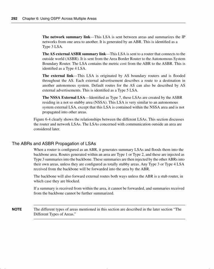
292 Chapter 6: Using OSPF Across Multiple Areas
The network summary link—This LSA is sent between areas and summarizes the IPnetworks from one area to another. It is generated by an ABR. This is identified as a Type 3 LSA.
The AS external ASBR summary link—This LSA is sent to a router that connects to theoutside world (ASBR). It is sent from the Area Border Router to the Autonomous SystemBoundary Router. The LSA contains the metric cost from the ABR to the ASBR. This isidentified as a Type 4 LSA.
The external link—This LSA is originated by AS boundary routers and is floodedthroughout the AS. Each external advertisement describes a route to a destination inanother autonomous system. Default routes for the AS can also be described by ASexternal advertisements. This is identified as a Type 5 LSA.
The NSSA External LSA—Identified as Type 7, these LSAs are created by the ASBR residing in a not so stubby area (NSSA). This LSA is very similar to an autonomous system external LSA, except that this LSA is contained within the NSSA area and is not propagated into other areas.
Figure 6-4 clearly shows the relationships between the different LSAs. This section discusses the router and network LSAs. The LSAs concerned with communication outside an area are considered later.
The ABRs and ASBR Propagation of LSAsWhen a router is configured as an ABR, it generates summary LSAs and floods them into the backbone area. Routes generated within an area are Type 1 or Type 2, and these are injected as Type 3 summaries into the backbone. These summaries are then injected by the other ABRs into their own areas, unless they are configured as totally stubby areas. Any Type 3 or Type 4 LSA received from the backbone will be forwarded into the area by the ABR.
The backbone will also forward external routes both ways unless the ABR is a stub router, in which case they are blocked.
If a summary is received from within the area, it cannot be forwarded, and summaries received from the backbone cannot be further summarized.
NOTE The different types of areas mentioned in this section are described in the later section “The Different Types of Areas.”
chpt_01.book Page 292 Thursday, December 21, 2000 6:22 PM
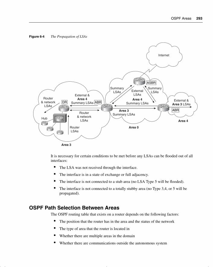
OSPF Areas 293
Figure 6-4 The Propagation of LSAs
It is necessary for certain conditions to be met before any LSAs can be flooded out of all interfaces:
• The LSA was not received through the interface.
• The interface is in a state of exchange or full adjacency.
• The interface is not connected to a stub area (no LSA Type 5 will be flooded).
• The interface is not connected to a totally stubby area (no Type 3,4, or 5 will be propagated).
OSPF Path Selection Between AreasThe OSPF routing table that exists on a router depends on the following factors:
• The position that the router has in the area and the status of the network
• The type of area that the router is located in
• Whether there are multiple areas in the domain
• Whether there are communications outside the autonomous system
ASBR
ABR
ABR
DR
Hub
RouterLSAs
Area 3
Router& network
LSAs
Router& network
LSAs
External &Area 4
Summary LSAs
SummaryLSAs
SummaryLSAs
Area 0
Area 3Summary LSAs
ExternalLSAs
Area 4Summary LSAs
Area 4
External &Area 3 LSAs
Internet
chpt_01.book Page 293 Thursday, December 21, 2000 6:22 PM
294 Chapter 6: Using OSPF Across Multiple Areas
Remember the sequence of events. The router receives LSAs. It builds the topological database. Then it runs the Dijkstra algorithm, from which the shortest path first is chosen and entered into the routing table. The routing table is therefore the conclusion of the decision-making process. It holds information on how that decision was made by including the metric for each link. This enables the network administrator to view the operation of the network.
Different LSAs hold different weighting in the decision-making process. It is preferable to take an internal route (within the area) to a remote network rather than to traverse multiple areas just to arrive at the same place. Not only does multiple-area traveling create unnecessary traffic, but it also can create a loop within the network.
The routing table reflects the network topology information and indicates where the remote network sits in relation to the local router.
The router will process the LSAs in this order:
Step 1 The internal LSA (Type 1 and 2).
Step 2 The LSAs of the AS (Type 3 and 4). If there is a route to the chosen network within the area (Type 1 or 2), this path will be kept.
Step 3 The external LSAs (Type 5).
Calculating the Cost of a Path to Another AreaThere are paths to networks in other areas, and then there are paths to networks in another AS. The costs of these paths are calculated slightly differently.
The Path to Another AreaThis is calculated as the smallest cost to the ABR, added to the smallest cost to the backbone. Thus, if there were two paths from the ABR into the backbone, the shortest (lowest-cost) path would be added to the cost of the path to the ABR.
The Path to Another ASExternal routes are routes passed between a router within the OSPF domain and a router in another autonomous system or routing domain. The routes discovered by OSPF in this way can have the cost of the path calculated in one of two ways:
• E1—The cost of the path to the ASBR is added to the external cost to the next-hop router outside the AS.
• E2—The cost of the path to the ASBR is all that is considered in the calculation. This is the default configuration. This is used when there is only one router advertising the route and no selection is required. If both an E1 and an E2 path are offered to the remote network, the E1 path will be used.
chpt_01.book Page 294 Thursday, December 21, 2000 6:22 PM
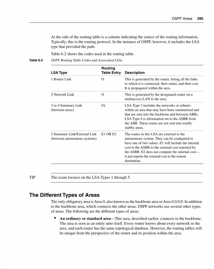
OSPF Areas 295
At the side of the routing table is a column indicating the source of the routing information. Typically, this is the routing protocol. In the instance of OSPF, however, it includes the LSA type that provided the path.
Table 6-2 shows the codes used in the routing table.
TIP The exam focuses on the LSA Types 1 through 5.
The Different Types of AreasThe only obligatory area is Area 0, also known as the backbone area or Area 0.0.0.0. In addition to the backbone area, which connects the other areas, OSPF networks use several other types of areas. The following are the different types of areas:
• An ordinary or standard area—This area, described earlier, connects to the backbone. The area is seen as an entity unto itself. Every router knows about every network in the area, and each router has the same topological database. However, the routing tables will be unique from the perspective of the router and its position within the area.
Table 6-2 OSPF Routing Table Codes and Associated LSAs
LSA TypeRouting Table Entry Description
1 Router Link O This is generated by the router, listing all the links to which it is connected, their status, and their cost. It is propagated within the area.
2 Network Link O This is generated by the designated router on a multiaccess LAN to the area.
3 or 4 Summary Link (between areas)
IA LSA Type 3 includes the networks or subnets within an area that may have been summarized and that are sent into the backbone and between ABRs. LSA Type 4 is information set to the ASBR from the ABR. These routes are not sent into totally stubby areas.
5 Summary Link/External Link (between autonomous systems)
E1 OR E2 The routes in this LSA are external to the autonomous system. They can be configured to have one of two values. E1 will include the internal cost to the ASBR to the external cost reported by the ASBR. E2 does not compute the internal cost—it just reports the external cost to the remote destination.
chpt_01.book Page 295 Thursday, December 21, 2000 6:22 PM

296 Chapter 6: Using OSPF Across Multiple Areas
• A stub area—This is an area that will not accept external summary routes. The LSAs blocked are Types 4 (summary link LSAs that are generated by the ABRs) and 5. The consequence is that the only way that a router within the area can see outside the autonomous system is via the configuration of a default route. Every router within the area can see every network within the area and the networks (summarized or not) within other areas. It is typically used in a hub-and-spoke network design.
• A totally stubby area—This area does not accept summary LSAs from the other areas or the external summary LSAs from outside the autonomous system. The LSAs blocked are Types 3, 4, and 5. The only way out of the area is via a configured default route. A default route is indicated as via 0.0.0.0. This type of area is particularly useful for remote sites that have few networks and limited connectivity with the rest of the network. This is a proprietary solution offered only by Cisco. Cisco recommends this solution if you have a totally Cisco shop because it keeps the topological databases and routing tables as small as possible.
• A not so stubby area (NSSA)—This area is used primarily to connect to ISPs, or when redistribution is required. In most respects, it is the same as the stub area. External routes are not propagated into or out of the area. It does not allow Type 4 or Type 5 LSAs. This seems contradictory to the opening sentence of this paragraph, which stated that this type of area was used to connect to an ISP or for redistribution, both of which are external routes to OSPF. It is contradictory, and this area designed for the exception. Possible examples are an area with a few stub networks but with a connection to a router that runs only RIP, or an area with its own connection to an Internet resource needed only by a certain division.
To create an area that is seen as a stub area but that can receive external routes that it will not propagate into the backbone area, and thus the rest of the OSPF domain, involves creating a NSSA. Another LSA, Type 7, is created for the NSSA. This LSA may be originated and communicated throughout the area, but it will not be propagated into other areas, including Area 0. If the information is to be propagated into throughout the AS, it is translated into an LSA Type 5 at the NSSA ABR.
It is not always possible to design the network and determine where redistribution is to occur. RFC 1587 deals with this subject.
• The backbone area—This area is often referred to as Area 0, and it connects all the other areas. It can propagate all the LSAs except for LSA Type 7, which would have been translated into LSA Type 5 by the ABR.
Some restrictions govern creating a stub or totally stubby area. These restrictions are in place because no external routes are allowed in these areas:
• No external routes are allowed.
• No virtual links are allowed.
• No redistribution is allowed.
chpt_01.book Page 296 Thursday, December 21, 2000 6:22 PM
Design Considerations in Multiple Area OSPF 297
• No ASBR routers are allowed.
• The area is not the backbone area.
• All the routers are configured to be stub routers.
Now that you understand many components of OSPF, it is important to focus on some of the design implications of creating multiple areas. This focus will reinforce the concepts detailed in the chapter.
Design Considerations in Multiple Area OSPFThe major design consideration in OSPF is how to divide the areas. This is of interest because it impacts the addressing scheme for IP within the network.
An OSPF network works best with a hierarchical design, in which the movement of data from one area to another comprises only a subset of the traffic within the area itself.
It is important to remember that with all the interarea traffic disseminated by the backbone, any reduction of overhead through a solid hierarchical design and summarization is beneficial. The lower the number of summary LSAs that need to be forwarded into the backbone area, the greater the benefit to the entire network. This will allow the network to grow more easily because the network overhead is at a minimum.
With this in mind, summarization is the natural consequence. As shown in Chapter 3, “IP Addressing,” summarization is not something that can be imposed on a network. It must be part of the initial network design. The addressing scheme must be devised to support the use of summarization.
WARNING Although it is possible to have more than three areas (per router) in OSPF, the Cisco Technical Assistance Center (TAC) recommends that a greater number of areas be created only after careful consideration. The results of having more areas will vary depending on the router (memory and CPU), as well as network topology and how many LSAs are generated. It is rec-ommended that you not exceed 50 routers in an OSPF area, but again, this is a guideline and not a strict rule. Remember that OSPF is very CPU-intensive in its maintenance of the databases and in the flooding of LSAs, as well as when it calculates the routing table, a process based on LSAs.
Therefore, it is not strictly the number of routers or areas that is important, but the number of routes and the stability of the network. These issues must be considered because the number of LSAs in your network is proportional to the amount of router resources required.
With this understanding, the general rules stated by Cisco for OSPF design are that the following numbers should not be exceeded:
• Routers per area: 50
• Neighbors per router: 60
chpt_01.book Page 297 Thursday, December 21, 2000 6:22 PM
298 Chapter 6: Using OSPF Across Multiple Areas
• Areas per router: 3
• A router may not be a DR or BDR for more than 1 LAN
SummarizationTwo types of summarization exist:
• Interarea summarization—This is performed at the ABR and creates Type 3 and 4 LSAs.
• External summarization—This is performed at the ASBR and creates Type 5 LSAs.
Both have the same fundamental requirement of contiguous addressing.
OSPF is stringent in its demand for a solid hierarchical design—so much so that it has devised some commands to deal with situations that break its rules of structure.
The Virtual LinkThe main dictate in OSPF is that the multiple areas must all connect directly to the backbone area. The connection to the backbone area is via an ABR, which is resident in both areas and holds a full topological database for each area.
OSPF has provided for the unhappy occasion that this rule cannot be followed. The solution is called a virtual link. If the new area cannot connect directly to the backbone area, a router is configured to connect to an area that does have direct connectivity.
The configuration commands create a tunnel to the ABR in the intermediary area. From the viewpoint of OSPF, it has a direct connection.
The reasons such a situation may occur are listed here:
• There is no physical connection to Area 0. This may be because the organization has recently merged with another or because of a network failure.
• There are two Area 0s because of a network merger. These Area 0s are connected by another area (for example, Area 5).
• The area is critical to the company, and an extra link has been configured for redundancy.
Although this is an extremely powerful command, it is not recommended as part of the design strategy for your network; instead, it is a temporary solution to a connectivity problem. It is necessary to ensure that the following is observed in creating a virtual link:
• Both routers must share a common area.
• One of the routers must be connected to Area 0.
chpt_01.book Page 298 Thursday, December 21, 2000 6:22 PM
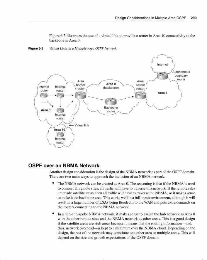
Design Considerations in Multiple Area OSPF 299
Figure 6-5 illustrates the use of a virtual link to provide a router in Area 10 connectivity to the backbone in Area 0.
Figure 6-5 Virtual Links in a Multiple-Area OSPF Network
OSPF over an NBMA Network Another design consideration is the design of the NBMA network as part of the OSPF domain. There are two main ways to approach the inclusion of an NBMA network:
• The NBMA network can be created as Area 0. The reasoning is that if the NBMA is used to connect all remote sites, all traffic will have to traverse this network. If the remote sites are made satellite areas, then all traffic will have to traverse the NBMA, so it makes sense to make it the backbone area. This works well in a full-mesh environment, although it will result in a large number of LSAs being flooded into the WAN and puts extra demands on the routers connecting to the NBMA network.
• In a hub-and-spoke NBMA network, it makes sense to assign the hub network as Area 0 with the other remote sites and the NBMA network as other areas. This is a good design if the satellite areas are stub areas because it means that the routing information—and, thus, network overhead—is kept to a minimum over the NBMA cloud. Depending on the design, the rest of the network may constitute one other area or multiple areas. This will depend on the size and growth expectations of the OSPF domain.
Internalrouter
Internalrouter
Internalrouter
Internalrouter
Area 3
Area 10
Areaborderrouter
Areaborderrouter
Area 0(backbone)
Backbonerouter
Internet
Autonomousboundary
router
Area 4
Virtual link
chpt_01.book Page 299 Thursday, December 21, 2000 6:22 PM
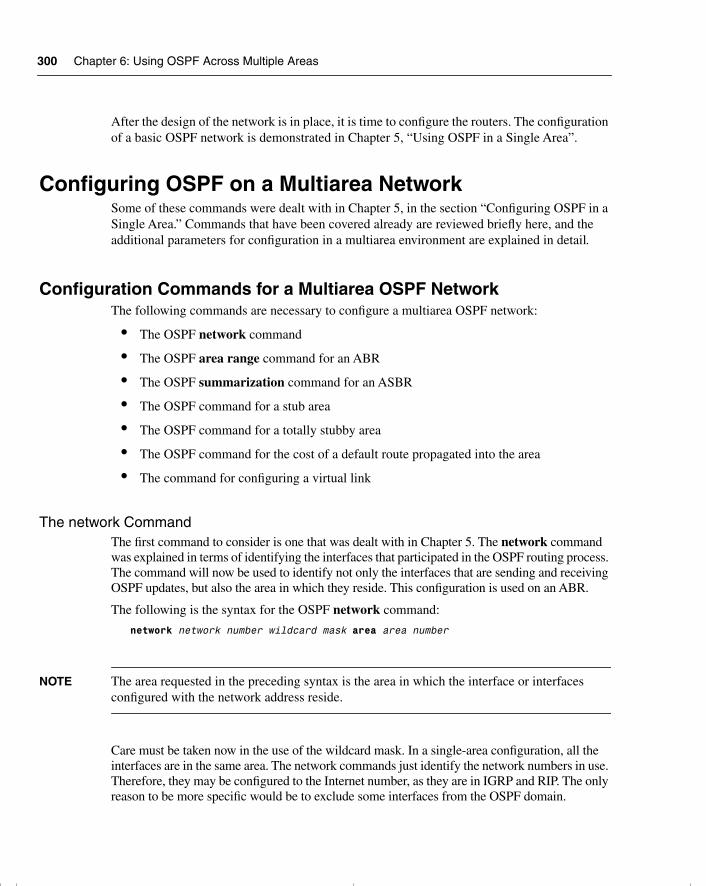
300 Chapter 6: Using OSPF Across Multiple Areas
After the design of the network is in place, it is time to configure the routers. The configuration of a basic OSPF network is demonstrated in Chapter 5, “Using OSPF in a Single Area”.
Configuring OSPF on a Multiarea NetworkSome of these commands were dealt with in Chapter 5, in the section “Configuring OSPF in a Single Area.” Commands that have been covered already are reviewed briefly here, and the additional parameters for configuration in a multiarea environment are explained in detail.
Configuration Commands for a Multiarea OSPF NetworkThe following commands are necessary to configure a multiarea OSPF network:
• The OSPF network command
• The OSPF area range command for an ABR
• The OSPF summarization command for an ASBR
• The OSPF command for a stub area
• The OSPF command for a totally stubby area
• The OSPF command for the cost of a default route propagated into the area
• The command for configuring a virtual link
The network CommandThe first command to consider is one that was dealt with in Chapter 5. The network command was explained in terms of identifying the interfaces that participated in the OSPF routing process. The command will now be used to identify not only the interfaces that are sending and receiving OSPF updates, but also the area in which they reside. This configuration is used on an ABR.
The following is the syntax for the OSPF network command:
network network number wildcard mask area area number
NOTE The area requested in the preceding syntax is the area in which the interface or interfaces configured with the network address reside.
Care must be taken now in the use of the wildcard mask. In a single-area configuration, all the interfaces are in the same area. The network commands just identify the network numbers in use. Therefore, they may be configured to the Internet number, as they are in IGRP and RIP. The only reason to be more specific would be to exclude some interfaces from the OSPF domain.
chpt_01.book Page 300 Thursday, December 21, 2000 6:22 PM
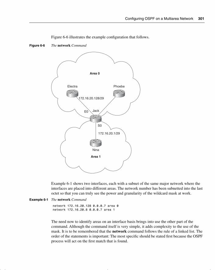
Configuring OSPF on a Multiarea Network 301
Figure 6-6 illustrates the example configuration that follows.
Figure 6-6 The network Command
Example 6-1 shows two interfaces, each with a subnet of the same major network where the interfaces are placed into different areas. The network number has been subnetted into the last octet so that you can truly see the power and granularity of the wildcard mask at work.
The need now to identify areas on an interface basis brings into use the other part of the command. Although the command itself is very simple, it adds complexity to the use of the mask. It is to be remembered that the network command follows the rule of a linked list. The order of the statements is important: The most specific should be stated first because the OSPF process will act on the first match that is found.
Example 6-1 The network Command
network 172.16.20.128 0.0.0.7 area 0network 172.16.20.8 0.0.0.7 area 1
Area 0
Electra Phoebe
Jack
Nina
Area 1
E0
S0
172.16.20.128/29
172.16.20.1/29
chpt_01.book Page 301 Thursday, December 21, 2000 6:22 PM
302 Chapter 6: Using OSPF Across Multiple Areas
The OSPF area range Command for an ABRThe area range command is configured on an ABR because it dictates the networks that will be advertised out of the area.
Use the area router configuration command with the range keyword to consolidate and summarize routes at an area boundary. Use the no form of this command to disable this function for the specified area:
area area-id range address maskno area area-id range address mask
In the preceding syntax, area-id is the identifier (ID) of the area about which routes are to be summarized. It can be specified as either a decimal value or an IP address. Here, address is the IP address, and mask is the IP mask.
Figure 6-7 illustrates the example configuration that follows.
Figure 6-7 The OSPF area range Command for an ABR
Area 0
Electra Phoebe
Jack
(ABR)
Nina
Area 1
S0
172.16.20.128/29
172.16.20.160/29 172.16.20.176/29
172.16.20.144/29
172.16.20.1/29
172.16.20.128/26
Megan Audrey
Networksummary
LSA, type 3
chpt_01.book Page 302 Thursday, December 21, 2000 6:22 PM
Configuring OSPF on a Multiarea Network 303
Example 6-2 shows the configuration required to summarize the following five individual subnets (which can address six hosts each) into one subnet. This summarized subnet may then be propagated across the OSPF network, saving both bandwidth and CPU:
• 172.16.20.128 /29
• 172.16.20.144 /29
• 172.16.20.160 /29
• 172.16.20.176 /29
These subnets are summarized into one subnet:
• 172.16.20.128 /26
This one subnet will then be propagated into Area 1.
NOTE The area ID requested is the area that the subnets originated from. It is not the destination area. The summarization update populates the topological databases of the routers in the destination area. These routers will need to know the source area for the summarized subnet to know where to send the data traffic.
The OSPF summarization Command for an ASBRThe summarization command is used on the ASBR to summarize the networks to be advertised to the outside world.
The syntax for the OSPF summarization command for an ASBR is as follows:
summary-address address mask [not advertise][tag tag]
The syntax for the OSPF summarization command for an ASBR is as follows:
summary-address address mask
In the preceding syntax, address is the summary address designated for a range of addresses, and mask is the IP subnet mask used for the summary route.
The design and implementation of the addressing scheme are crucial to the success of the OSPF network and cannot be stressed too strongly. Refer to Chapter 3 for details on IP addressing and summarization.
Example 6-2 The OSPF area range Command for an ABR
Router Jackrouter ospf 100network 172.16.20.128 0.0.0.7 area 0network 172.16.20.8 0.0.0.7 area 1area 0 range 172.16.20.128 255.255.255.192
chpt_01.book Page 303 Thursday, December 21, 2000 6:22 PM
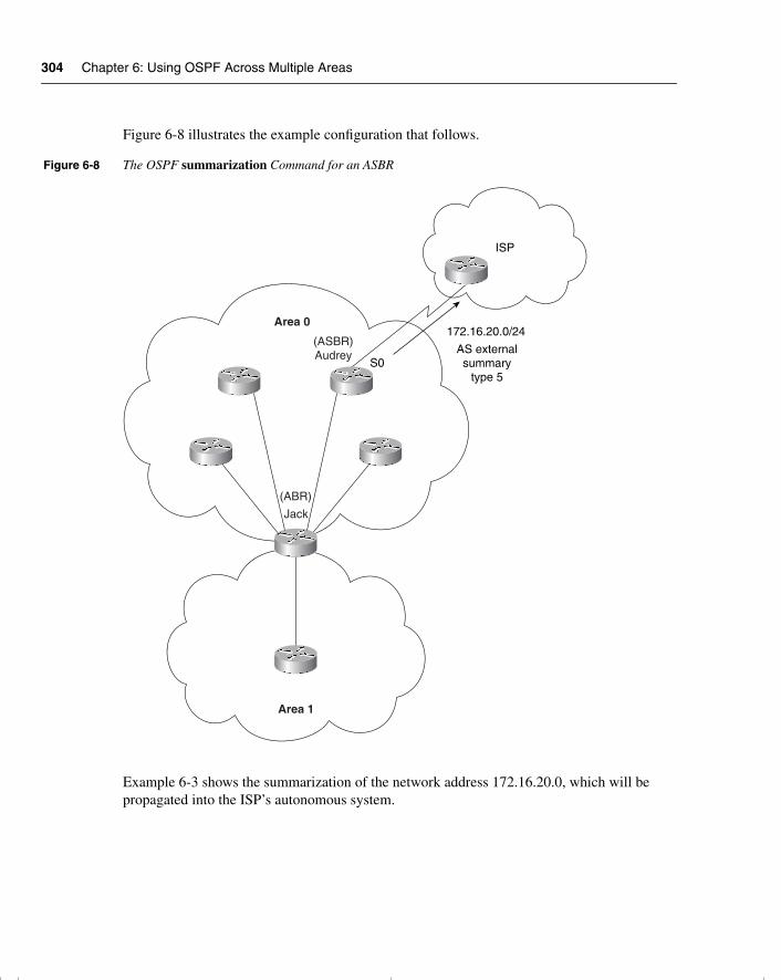
304 Chapter 6: Using OSPF Across Multiple Areas
Figure 6-8 illustrates the example configuration that follows.
Figure 6-8 The OSPF summarization Command for an ASBR
Example 6-3 shows the summarization of the network address 172.16.20.0, which will be propagated into the ISP’s autonomous system.
Area 0
(ASBR)Audrey
Jack
(ABR)
Area 1
S0
172.16.20.0/24
AS externalsummary
type 5
ISP
chpt_01.book Page 304 Thursday, December 21, 2000 6:22 PM
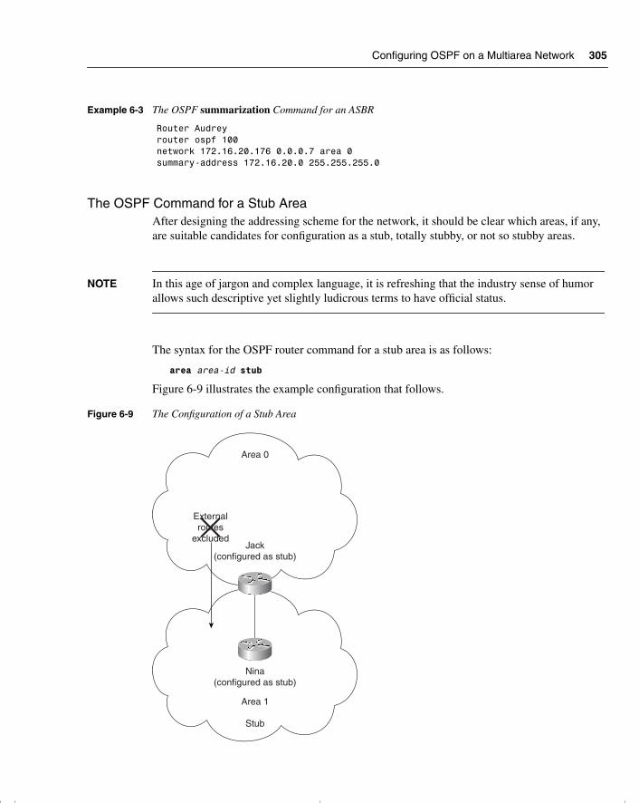
Configuring OSPF on a Multiarea Network 305
The OSPF Command for a Stub AreaAfter designing the addressing scheme for the network, it should be clear which areas, if any, are suitable candidates for configuration as a stub, totally stubby, or not so stubby areas.
NOTE In this age of jargon and complex language, it is refreshing that the industry sense of humor allows such descriptive yet slightly ludicrous terms to have official status.
The syntax for the OSPF router command for a stub area is as follows:
area area-id stub
Figure 6-9 illustrates the example configuration that follows.
Figure 6-9 The Configuration of a Stub Area
Example 6-3 The OSPF summarization Command for an ASBR
Router Audreyrouter ospf 100network 172.16.20.176 0.0.0.7 area 0summary-address 172.16.20.0 255.255.255.0
Area 0
Jack(configured as stub)
Area 1
Stub
Nina(configured as stub)
Externalroutes
excluded
chpt_01.book Page 305 Thursday, December 21, 2000 6:22 PM
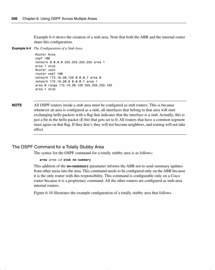
306 Chapter 6: Using OSPF Across Multiple Areas
Example 6-4 shows the creation of a stub area. Note that both the ABR and the internal router share this configuration.
NOTE All OSPF routers inside a stub area must be configured as stub routers. This is because whenever an area is configured as a stub, all interfaces that belong to that area will start exchanging hello packets with a flag that indicates that the interface is a stub. Actually, this is just a bit in the hello packet (E bit) that gets set to 0. All routers that have a common segment must agree on that flag. If they don’t, they will not become neighbors, and routing will not take effect.
The OSPF Command for a Totally Stubby AreaThe syntax for the OSPF command for a totally stubby area is as follows:
area area-id stub no-summary
This addition of the no-summary parameter informs the ABR not to send summary updates from other areas into the area. This command needs to be configured only on the ABR because it is the only router with this responsibility. This command is configurable only on a Cisco router because it is a proprietary command. All the other routers are configured as stub-area internal routers.
Figure 6-10 illustrates the example configuration of a totally stubby area that follows.
Example 6-4 The Configuration of a Stub Area
Router Ninaospf 100network 0.0.0.0 255.255.255.255 area 1area 1 stubRouter Jackrouter ospf 100network 172.16.20.128 0.0.0.7 area 0network 172.16.20.8 0.0.0.7 area 1area 0 range 172.16.20.128 255.255.255.192area 1 stub
chpt_01.book Page 306 Thursday, December 21, 2000 6:22 PM
Configuring OSPF on a Multiarea Network 307
Figure 6-10 The Configuration of a Totally Stubby Area
Example 6-5 shows the configuration of a totally stubby area.
As a totally stubby area, no summary or external routes are propagated by the ABR into the area. To reach networks and hosts outside their area, a workstation must send to a default route, which the ABR advertises into the area.
Example 6-5 The Configuration of a Totally Stubby Area
Router Phoebeospf 100network 172.16.20.144 0.0.0.7 area 0network 172.16.20.16 0.0.0.7 area 2area 2 stub no-summaryarea 0 range 172.16.20.128 255.255.255.192Router Martinrouter ospf 100network 0.0.0.0 255.255.255.255 area 2area 2 stub
Area 0
Jack(configured as stub)
Martin(configured as stub)
Phoebe(configured astotally stubby)
Area 1
Area 2
Totally stubby
Stub
Nina(configured as stub)
Summary externalroutes excluded
chpt_01.book Page 307 Thursday, December 21, 2000 6:22 PM
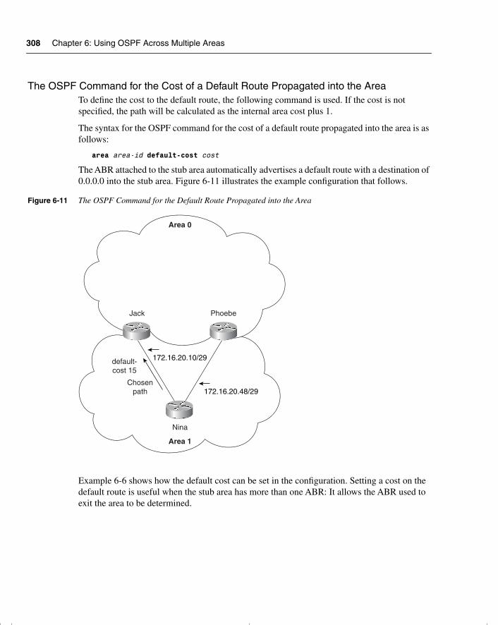
308 Chapter 6: Using OSPF Across Multiple Areas
The OSPF Command for the Cost of a Default Route Propagated into the AreaTo define the cost to the default route, the following command is used. If the cost is not specified, the path will be calculated as the internal area cost plus 1.
The syntax for the OSPF command for the cost of a default route propagated into the area is as follows:
area area-id default-cost cost
The ABR attached to the stub area automatically advertises a default route with a destination of 0.0.0.0 into the stub area. Figure 6-11 illustrates the example configuration that follows.
Figure 6-11 The OSPF Command for the Default Route Propagated into the Area
Example 6-6 shows how the default cost can be set in the configuration. Setting a cost on the default route is useful when the stub area has more than one ABR: It allows the ABR used to exit the area to be determined.
Area 0
Jack Phoebe
Area 1
Nina
default-cost 15
Chosenpath 172.16.20.48/29
172.16.20.10/29
chpt_01.book Page 308 Thursday, December 21, 2000 6:22 PM
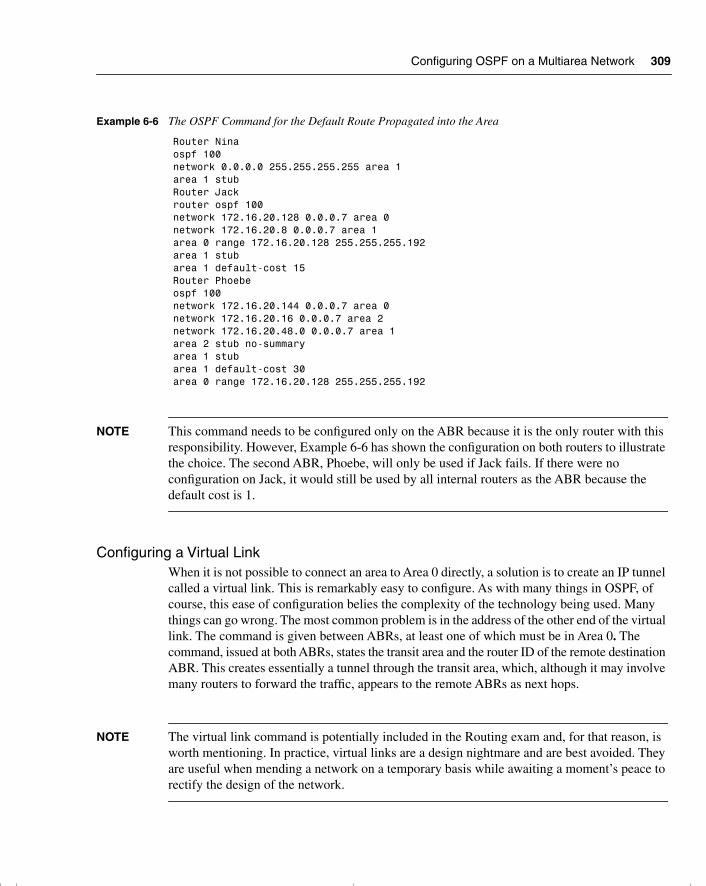
Configuring OSPF on a Multiarea Network 309
NOTE This command needs to be configured only on the ABR because it is the only router with this responsibility. However, Example 6-6 has shown the configuration on both routers to illustrate the choice. The second ABR, Phoebe, will only be used if Jack fails. If there were no configuration on Jack, it would still be used by all internal routers as the ABR because the default cost is 1.
Configuring a Virtual LinkWhen it is not possible to connect an area to Area 0 directly, a solution is to create an IP tunnel called a virtual link. This is remarkably easy to configure. As with many things in OSPF, of course, this ease of configuration belies the complexity of the technology being used. Many things can go wrong. The most common problem is in the address of the other end of the virtual link. The command is given between ABRs, at least one of which must be in Area 0. The command, issued at both ABRs, states the transit area and the router ID of the remote destination ABR. This creates essentially a tunnel through the transit area, which, although it may involve many routers to forward the traffic, appears to the remote ABRs as next hops.
NOTE The virtual link command is potentially included in the Routing exam and, for that reason, is worth mentioning. In practice, virtual links are a design nightmare and are best avoided. They are useful when mending a network on a temporary basis while awaiting a moment’s peace to rectify the design of the network.
Example 6-6 The OSPF Command for the Default Route Propagated into the Area
Router Ninaospf 100network 0.0.0.0 255.255.255.255 area 1area 1 stubRouter Jackrouter ospf 100network 172.16.20.128 0.0.0.7 area 0network 172.16.20.8 0.0.0.7 area 1area 0 range 172.16.20.128 255.255.255.192area 1 stubarea 1 default-cost 15Router Phoebeospf 100network 172.16.20.144 0.0.0.7 area 0network 172.16.20.16 0.0.0.7 area 2network 172.16.20.48.0 0.0.0.7 area 1area 2 stub no-summaryarea 1 stubarea 1 default-cost 30area 0 range 172.16.20.128 255.255.255.192
chpt_01.book Page 309 Thursday, December 21, 2000 6:22 PM
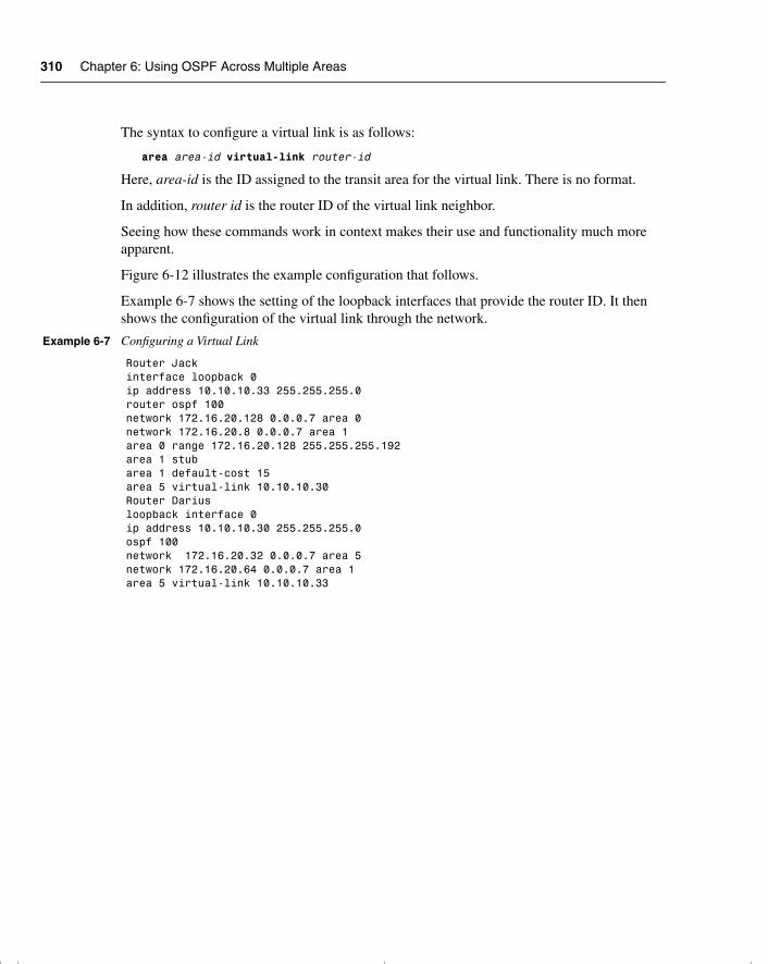
310 Chapter 6: Using OSPF Across Multiple Areas
The syntax to configure a virtual link is as follows:
area area-id virtual-link router-id
Here, area-id is the ID assigned to the transit area for the virtual link. There is no format.
In addition, router id is the router ID of the virtual link neighbor.
Seeing how these commands work in context makes their use and functionality much more apparent.
Figure 6-12 illustrates the example configuration that follows.
Example 6-7 shows the setting of the loopback interfaces that provide the router ID. It then shows the configuration of the virtual link through the network.
Example 6-7 Configuring a Virtual Link
Router Jackinterface loopback 0ip address 10.10.10.33 255.255.255.0router ospf 100network 172.16.20.128 0.0.0.7 area 0network 172.16.20.8 0.0.0.7 area 1area 0 range 172.16.20.128 255.255.255.192area 1 stubarea 1 default-cost 15area 5 virtual-link 10.10.10.30 Router Dariusloopback interface 0ip address 10.10.10.30 255.255.255.0ospf 100network 172.16.20.32 0.0.0.7 area 5network 172.16.20.64 0.0.0.7 area 1area 5 virtual-link 10.10.10.33
chpt_01.book Page 310 Thursday, December 21, 2000 6:22 PM
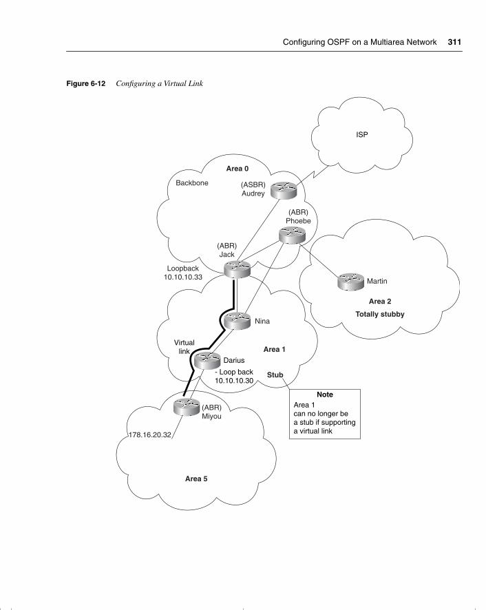
Configuring OSPF on a Multiarea Network 311
Figure 6-12 Configuring a Virtual Link
Area 0
(ABR)Jack
(ABR)Miyou
(ASBR)Audrey
Martin
(ABR)Phoebe
Area 1
Area 2
Totally stubby
Stub
Nina
Virtuallink
Darius
- Loop back10.10.10.30
NoteArea 1can no longer bea stub if supportinga virtual link
Area 5
178.16.20.32
ISP
Backbone
Loopback10.10.10.33
chpt_01.book Page 311 Thursday, December 21, 2000 6:22 PM
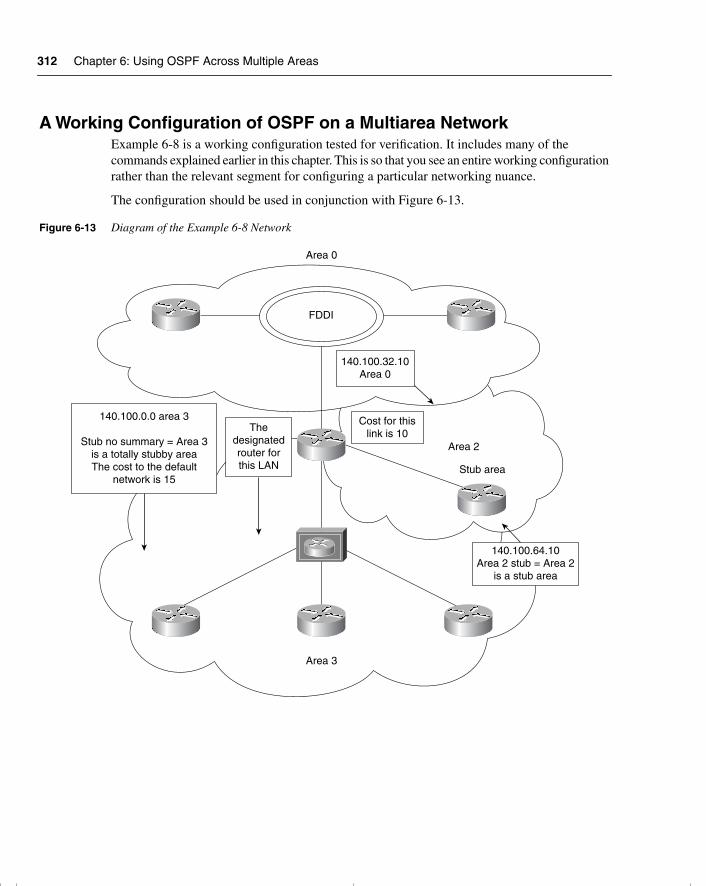
312 Chapter 6: Using OSPF Across Multiple Areas
A Working Configuration of OSPF on a Multiarea NetworkExample 6-8 is a working configuration tested for verification. It includes many of the commands explained earlier in this chapter. This is so that you see an entire working configuration rather than the relevant segment for configuring a particular networking nuance.
The configuration should be used in conjunction with Figure 6-13.
Figure 6-13 Diagram of the Example 6-8 Network
Area 0
Area 3
Area 2
Stub area
140.100.32.10Area 0
Cost for thislink is 10The
designatedrouter forthis LAN
140.100.64.10Area 2 stub = Area 2
is a stub area
140.100.0.0 area 3
Stub no summary = Area 3is a totally stubby areaThe cost to the default
network is 15
FDDI
chpt_01.book Page 312 Thursday, December 21, 2000 6:22 PM
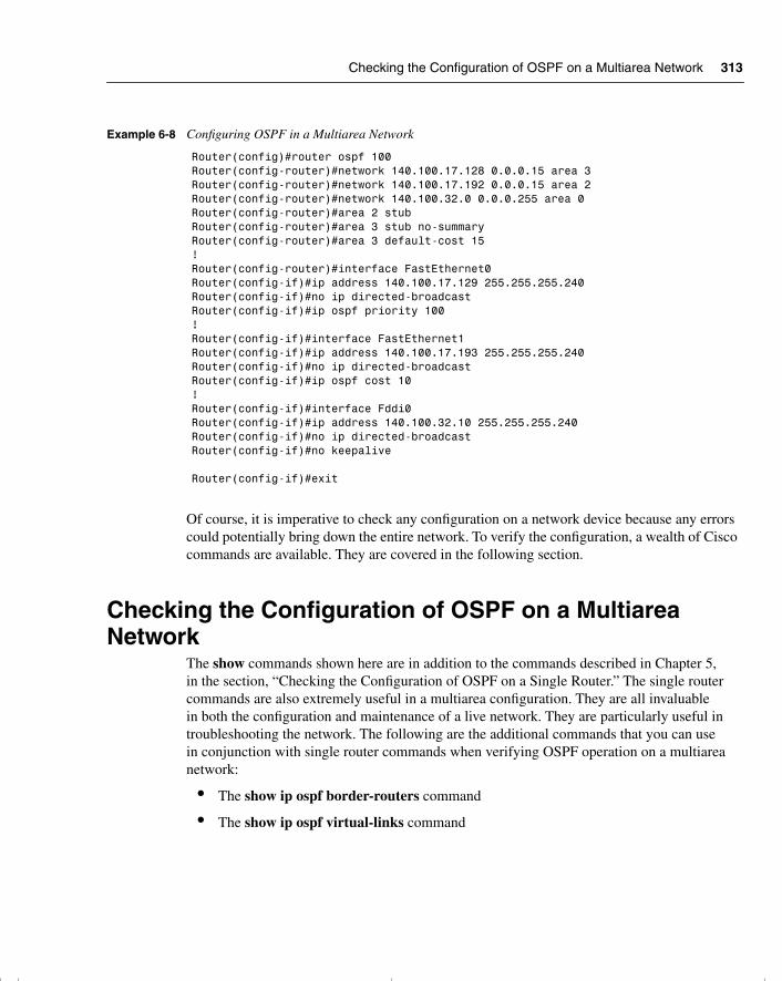
Checking the Configuration of OSPF on a Multiarea Network 313
Of course, it is imperative to check any configuration on a network device because any errors could potentially bring down the entire network. To verify the configuration, a wealth of Cisco commands are available. They are covered in the following section.
Checking the Configuration of OSPF on a Multiarea Network
The show commands shown here are in addition to the commands described in Chapter 5, in the section, “Checking the Configuration of OSPF on a Single Router.” The single router commands are also extremely useful in a multiarea configuration. They are all invaluable in both the configuration and maintenance of a live network. They are particularly useful in troubleshooting the network. The following are the additional commands that you can use in conjunction with single router commands when verifying OSPF operation on a multiarea network:
• The show ip ospf border-routers command
• The show ip ospf virtual-links command
Example 6-8 Configuring OSPF in a Multiarea Network
Router(config)#router ospf 100Router(config-router)#network 140.100.17.128 0.0.0.15 area 3Router(config-router)#network 140.100.17.192 0.0.0.15 area 2Router(config-router)#network 140.100.32.0 0.0.0.255 area 0Router(config-router)#area 2 stubRouter(config-router)#area 3 stub no-summaryRouter(config-router)#area 3 default-cost 15! Router(config-router)#interface FastEthernet0Router(config-if)#ip address 140.100.17.129 255.255.255.240Router(config-if)#no ip directed-broadcastRouter(config-if)#ip ospf priority 100!Router(config-if)#interface FastEthernet1Router(config-if)#ip address 140.100.17.193 255.255.255.240Router(config-if)#no ip directed-broadcastRouter(config-if)#ip ospf cost 10!Router(config-if)#interface Fddi0Router(config-if)#ip address 140.100.32.10 255.255.255.240Router(config-if)#no ip directed-broadcastRouter(config-if)#no keepalive
Router(config-if)#exit
chpt_01.book Page 313 Thursday, December 21, 2000 6:22 PM
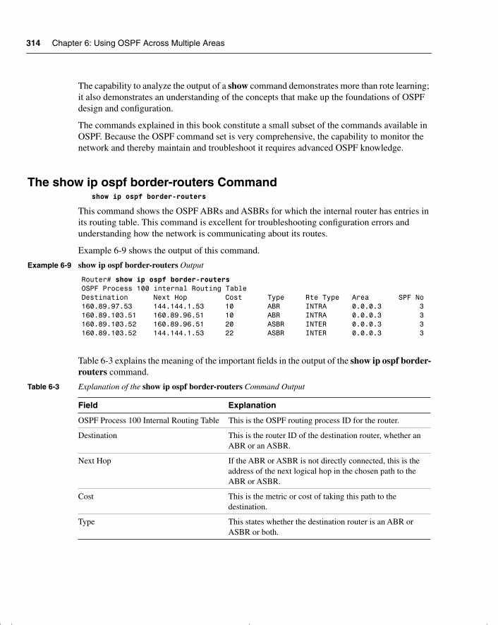
314 Chapter 6: Using OSPF Across Multiple Areas
The capability to analyze the output of a show command demonstrates more than rote learning; it also demonstrates an understanding of the concepts that make up the foundations of OSPF design and configuration.
The commands explained in this book constitute a small subset of the commands available in OSPF. Because the OSPF command set is very comprehensive, the capability to monitor the network and thereby maintain and troubleshoot it requires advanced OSPF knowledge.
The show ip ospf border-routers Commandshow ip ospf border-routers
This command shows the OSPF ABRs and ASBRs for which the internal router has entries in its routing table. This command is excellent for troubleshooting configuration errors and understanding how the network is communicating about its routes.
Example 6-9 shows the output of this command.
Table 6-3 explains the meaning of the important fields in the output of the show ip ospf border-routers command.
Example 6-9 show ip ospf border-routers Output
Router# show ip ospf border-routersOSPF Process 100 internal Routing TableDestination Next Hop Cost Type Rte Type Area SPF No160.89.97.53 144.144.1.53 10 ABR INTRA 0.0.0.3 3160.89.103.51 160.89.96.51 10 ABR INTRA 0.0.0.3 3160.89.103.52 160.89.96.51 20 ASBR INTER 0.0.0.3 3160.89.103.52 144.144.1.53 22 ASBR INTER 0.0.0.3 3
Table 6-3 Explanation of the show ip ospf border-routers Command Output
Field Explanation
OSPF Process 100 Internal Routing Table This is the OSPF routing process ID for the router.
Destination This is the router ID of the destination router, whether an ABR or an ASBR.
Next Hop If the ABR or ASBR is not directly connected, this is the address of the next logical hop in the chosen path to the ABR or ASBR.
Cost This is the metric or cost of taking this path to the destination.
Type This states whether the destination router is an ABR or ASBR or both.
chpt_01.book Page 314 Thursday, December 21, 2000 6:22 PM
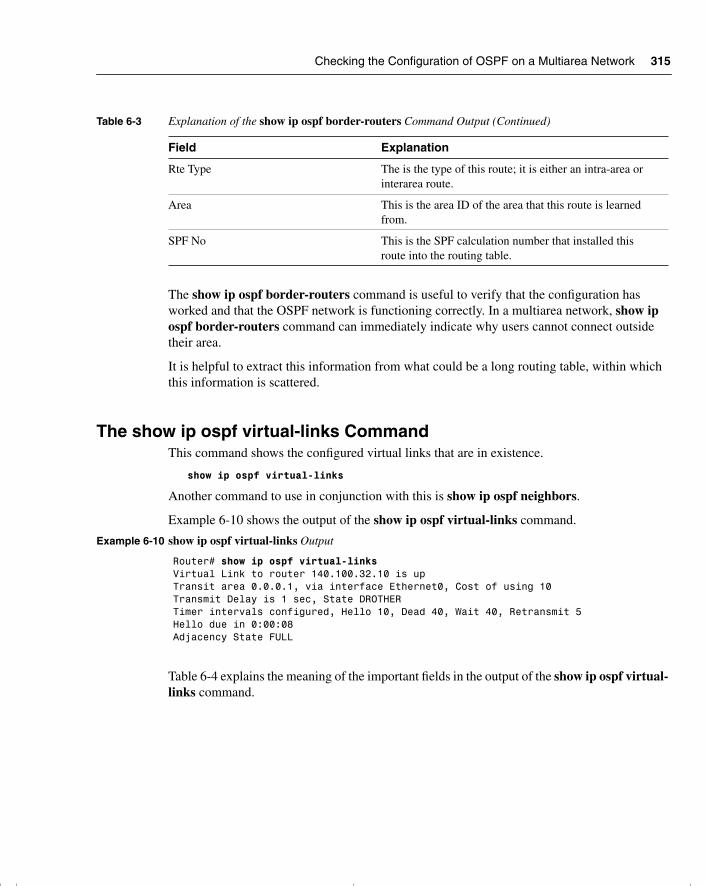
Checking the Configuration of OSPF on a Multiarea Network 315
The show ip ospf border-routers command is useful to verify that the configuration has worked and that the OSPF network is functioning correctly. In a multiarea network, show ip ospf border-routers command can immediately indicate why users cannot connect outside their area.
It is helpful to extract this information from what could be a long routing table, within which this information is scattered.
The show ip ospf virtual-links CommandThis command shows the configured virtual links that are in existence.
show ip ospf virtual-links
Another command to use in conjunction with this is show ip ospf neighbors.
Example 6-10 shows the output of the show ip ospf virtual-links command.
Table 6-4 explains the meaning of the important fields in the output of the show ip ospf virtual-links command.
Rte Type The is the type of this route; it is either an intra-area or interarea route.
Area This is the area ID of the area that this route is learned from.
SPF No This is the SPF calculation number that installed this route into the routing table.
Example 6-10 show ip ospf virtual-links Output
Router# show ip ospf virtual-linksVirtual Link to router 140.100.32.10 is upTransit area 0.0.0.1, via interface Ethernet0, Cost of using 10Transmit Delay is 1 sec, State DROTHERTimer intervals configured, Hello 10, Dead 40, Wait 40, Retransmit 5Hello due in 0:00:08Adjacency State FULL
Table 6-3 Explanation of the show ip ospf border-routers Command Output (Continued)
Field Explanation
chpt_01.book Page 315 Thursday, December 21, 2000 6:22 PM
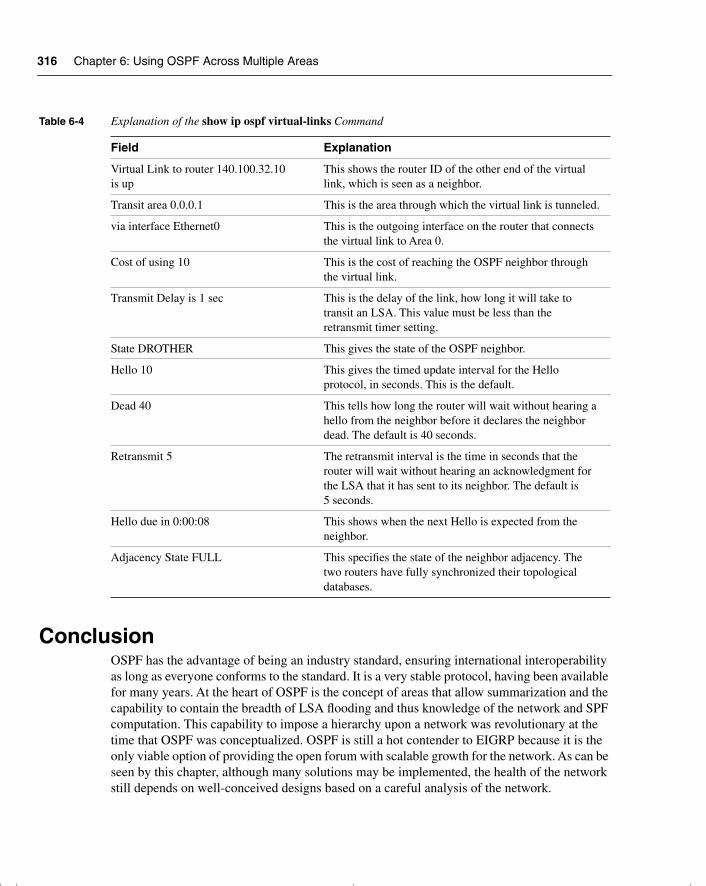
316 Chapter 6: Using OSPF Across Multiple Areas
ConclusionOSPF has the advantage of being an industry standard, ensuring international interoperability as long as everyone conforms to the standard. It is a very stable protocol, having been available for many years. At the heart of OSPF is the concept of areas that allow summarization and the capability to contain the breadth of LSA flooding and thus knowledge of the network and SPF computation. This capability to impose a hierarchy upon a network was revolutionary at the time that OSPF was conceptualized. OSPF is still a hot contender to EIGRP because it is the only viable option of providing the open forum with scalable growth for the network. As can be seen by this chapter, although many solutions may be implemented, the health of the network still depends on well-conceived designs based on a careful analysis of the network.
Table 6-4 Explanation of the show ip ospf virtual-links Command
Field Explanation
Virtual Link to router 140.100.32.10 is up
This shows the router ID of the other end of the virtual link, which is seen as a neighbor.
Transit area 0.0.0.1 This is the area through which the virtual link is tunneled.
via interface Ethernet0 This is the outgoing interface on the router that connects the virtual link to Area 0.
Cost of using 10 This is the cost of reaching the OSPF neighbor through the virtual link.
Transmit Delay is 1 sec This is the delay of the link, how long it will take to transit an LSA. This value must be less than the retransmit timer setting.
State DROTHER This gives the state of the OSPF neighbor.
Hello 10 This gives the timed update interval for the Hello protocol, in seconds. This is the default.
Dead 40 This tells how long the router will wait without hearing a hello from the neighbor before it declares the neighbor dead. The default is 40 seconds.
Retransmit 5 The retransmit interval is the time in seconds that the router will wait without hearing an acknowledgment for the LSA that it has sent to its neighbor. The default is 5 seconds.
Hello due in 0:00:08 This shows when the next Hello is expected from the neighbor.
Adjacency State FULL This specifies the state of the neighbor adjacency. The two routers have fully synchronized their topological databases.
chpt_01.book Page 316 Thursday, December 21, 2000 6:22 PM
OSPF Routers 317
Foundation Summary
The “Foundation Summary” is a collection of quick reference information that provides a convenient review of many key concepts in this chapter. For those of you who already feel comfortable with the topics in this chapter, this summary will help you recall a few details. For those of you who just read this chapter, this review should help solidify some key facts. For any of you doing your final preparations before the exam, these tables and figures will be a convenient way to review the day before the exam.
OSPF RoutersThe following list identifies the different OSPF routers:
• Internal router—Within an area, the functionality of the router is straightforward. It is responsible for maintaining a current and accurate database of every subnet within the area. It is also responsible for forwarding data to other networks by the shortest path. Flooding of routing updates is confined to the area.
• Backbone router—The design rules for OSPF require that all the areas be connected through a single area known as the backbone area or Area 0. A router within this area is referred to as a backbone router. It may also be an internal router or an Area Border Router.
• Area Border Router (ABR)—This router is responsible for connecting two or more areas. It holds a full topological database for each area to which it is connected and sends LSA updates between the areas. These LSA updates are summary updates of the subnets within an area. It is at the area border that summarization should be configured for OSPF because this is where the LSAs make use of the reduced routing updates to minimize the routing overhead on both the network and the routers.
• Autonomous System Boundary Router (ASBR)—To connect to the outside world, or to any other routing protocol, you need to leave the OSPF domain. OSPF is an interior routing protocol or Interior Gateway Protocol (IGP); gateway is an older term for a router. The router configured for this duty is the ASBR. Although you can place this router anywhere in the OSPF hierarchical design, it should reside in the backbone area. Because any traffic leaving the OSPF domain will likely also leave the router’s area, it makes sense to place the ASBR in a central location that all traffic leaving its area must traverse.
chpt_01.book Page 317 Thursday, December 21, 2000 6:22 PM
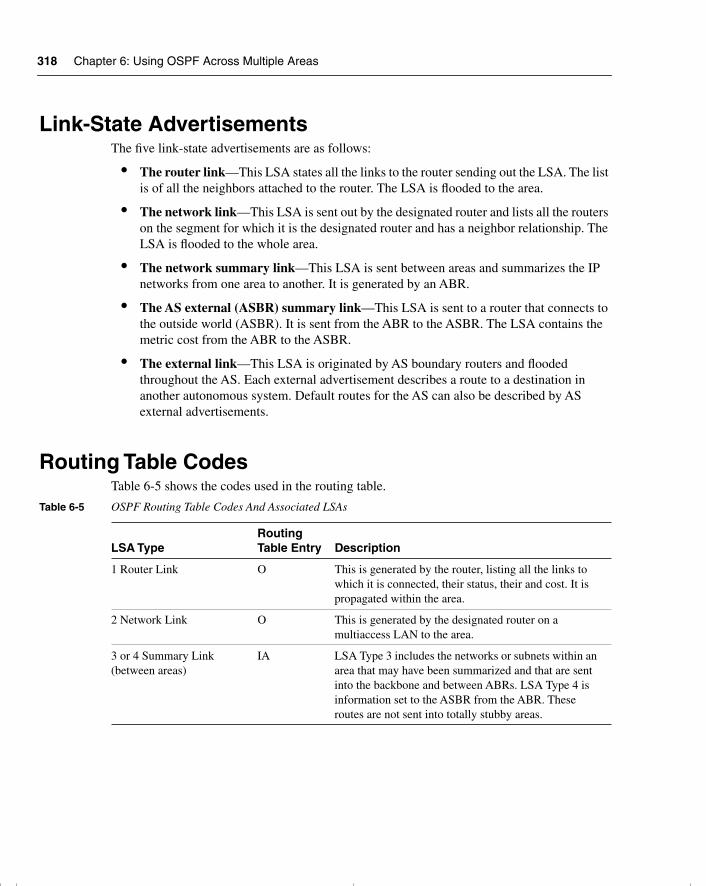
318 Chapter 6: Using OSPF Across Multiple Areas
Link-State AdvertisementsThe five link-state advertisements are as follows:
• The router link—This LSA states all the links to the router sending out the LSA. The list is of all the neighbors attached to the router. The LSA is flooded to the area.
• The network link—This LSA is sent out by the designated router and lists all the routers on the segment for which it is the designated router and has a neighbor relationship. The LSA is flooded to the whole area.
• The network summary link—This LSA is sent between areas and summarizes the IP networks from one area to another. It is generated by an ABR.
• The AS external (ASBR) summary link—This LSA is sent to a router that connects to the outside world (ASBR). It is sent from the ABR to the ASBR. The LSA contains the metric cost from the ABR to the ASBR.
• The external link—This LSA is originated by AS boundary routers and flooded throughout the AS. Each external advertisement describes a route to a destination in another autonomous system. Default routes for the AS can also be described by AS external advertisements.
Routing Table CodesTable 6-5 shows the codes used in the routing table.
Table 6-5 OSPF Routing Table Codes And Associated LSAs
LSA TypeRouting Table Entry Description
1 Router Link O This is generated by the router, listing all the links to which it is connected, their status, their and cost. It is propagated within the area.
2 Network Link O This is generated by the designated router on a multiaccess LAN to the area.
3 or 4 Summary Link (between areas)
IA LSA Type 3 includes the networks or subnets within an area that may have been summarized and that are sent into the backbone and between ABRs. LSA Type 4 is information set to the ASBR from the ABR. These routes are not sent into totally stubby areas.
chpt_01.book Page 318 Thursday, December 21, 2000 6:22 PM
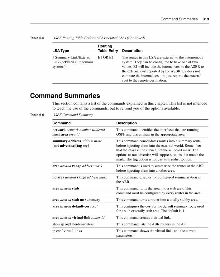
Command Summaries 319
Command SummariesThis section contains a list of the commands explained in this chapter. This list is not intended to teach the use of the commands, but to remind you of the options available.
5 Summary Link/External Link (between autonomous systems)
E1 OR E2 The routes in this LSA are external to the autonomous system. They can be configured to have one of two values. E1 will include the internal cost to the ASBR to the external cost reported by the ASBR. E2 does not compute the internal cost—it just reports the external cost to the remote destination.
Table 6-6 OSPF Command Summary
Command Description
network network number wildcard mask area area id
This command identifies the interfaces that are running OSPF and places them in the appropriate area.
summary-address address mask [not-advertise][tag tag]
This command consolidates routes into a summary route before injecting them into the external world. Remember that the mask is the subnet, not the wildcard mask. The options to not advertise will suppress routes that match the mask. The tag option is for use with redistribution.
area area-id range address mask This command is used to summarize the routes at the ABR before injecting them into another area.
no area area-id range address mask This command disables the configured summarization at the ABR.
area area-id stub This command turns the area into a stub area. This command must be configured by every router in the area.
area area-id stub no-summary This command turns a router into a totally stubby area.
area area-id default-cost cost This configures the cost for the default summary route used for a stub or totally stub area. The default is 1.
area area-id virtual-link router-id This command creates a virtual link.
show ip ospf border-routers This command lists the ABR routers in the AS.
ip ospf virtual-links This command shows the virtual links and the current parameters.
Table 6-5 OSPF Routing Table Codes And Associated LSAs (Continued)
LSA TypeRouting Table Entry Description
chpt_01.book Page 319 Thursday, December 21, 2000 6:22 PM
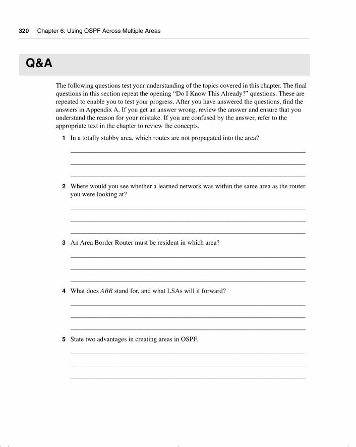
320 Chapter 6: Using OSPF Across Multiple Areas
Q&A
The following questions test your understanding of the topics covered in this chapter. The final questions in this section repeat the opening “Do I Know This Already?” questions. These are repeated to enable you to test your progress. After you have answered the questions, find the answers in Appendix A. If you get an answer wrong, review the answer and ensure that you understand the reason for your mistake. If you are confused by the answer, refer to the appropriate text in the chapter to review the concepts.
1 In a totally stubby area, which routes are not propagated into the area?
______________________________________________________________________
______________________________________________________________________
______________________________________________________________________
2 Where would you see whether a learned network was within the same area as the router you were looking at?
______________________________________________________________________
______________________________________________________________________
______________________________________________________________________
3 An Area Border Router must be resident in which area?
______________________________________________________________________
______________________________________________________________________
______________________________________________________________________
4 What does ABR stand for, and what LSAs will it forward?
______________________________________________________________________
______________________________________________________________________
______________________________________________________________________
5 State two advantages in creating areas in OSPF.
______________________________________________________________________
______________________________________________________________________
______________________________________________________________________
chpt_01.book Page 320 Thursday, December 21, 2000 6:22 PM
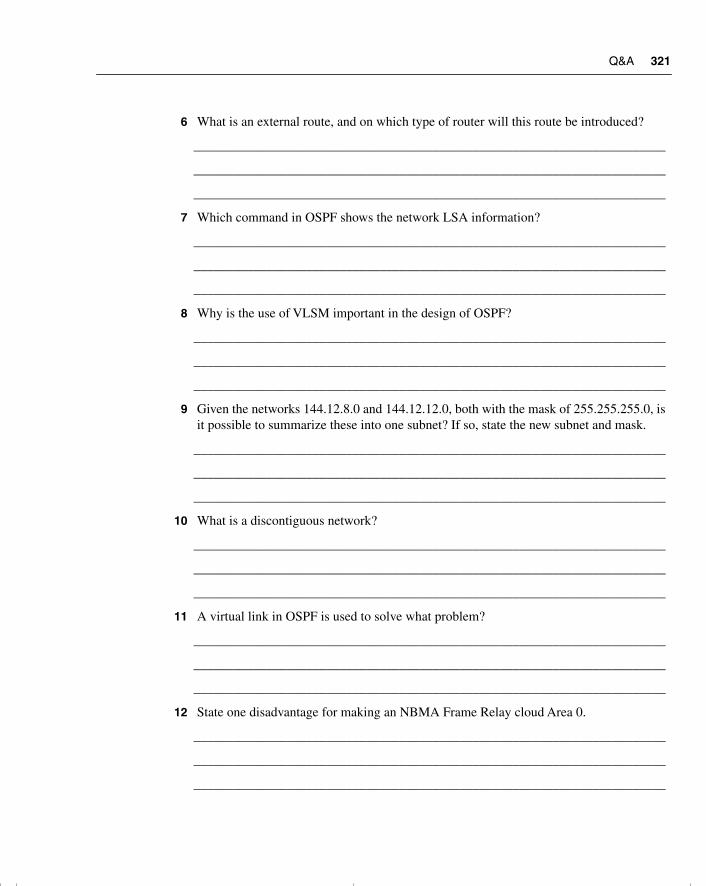
Q&A 321
6 What is an external route, and on which type of router will this route be introduced?
_______________________________________________________________________
_______________________________________________________________________
_______________________________________________________________________
7 Which command in OSPF shows the network LSA information?
_______________________________________________________________________
_______________________________________________________________________
_______________________________________________________________________
8 Why is the use of VLSM important in the design of OSPF?
_______________________________________________________________________
_______________________________________________________________________
_______________________________________________________________________
9 Given the networks 144.12.8.0 and 144.12.12.0, both with the mask of 255.255.255.0, is it possible to summarize these into one subnet? If so, state the new subnet and mask.
_______________________________________________________________________
_______________________________________________________________________
_______________________________________________________________________
10 What is a discontiguous network?
_______________________________________________________________________
_______________________________________________________________________
_______________________________________________________________________
11 A virtual link in OSPF is used to solve what problem?
_______________________________________________________________________
_______________________________________________________________________
_______________________________________________________________________
12 State one disadvantage for making an NBMA Frame Relay cloud Area 0.
_______________________________________________________________________
_______________________________________________________________________
_______________________________________________________________________
chpt_01.book Page 321 Thursday, December 21, 2000 6:22 PM
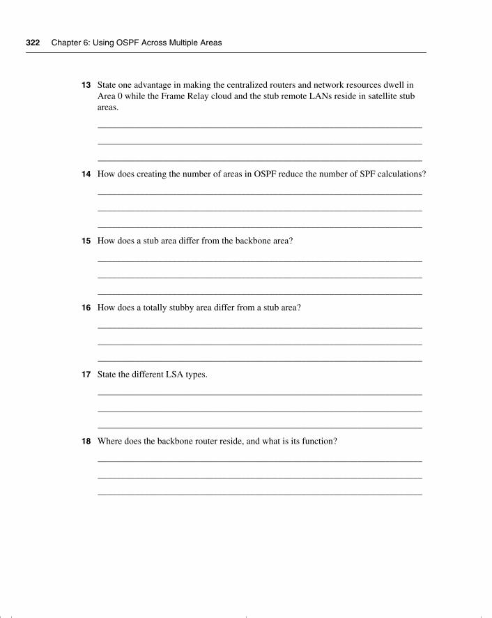
322 Chapter 6: Using OSPF Across Multiple Areas
13 State one advantage in making the centralized routers and network resources dwell in Area 0 while the Frame Relay cloud and the stub remote LANs reside in satellite stub areas.
______________________________________________________________________
______________________________________________________________________
______________________________________________________________________
14 How does creating the number of areas in OSPF reduce the number of SPF calculations?
______________________________________________________________________
______________________________________________________________________
______________________________________________________________________
15 How does a stub area differ from the backbone area?
______________________________________________________________________
______________________________________________________________________
______________________________________________________________________
16 How does a totally stubby area differ from a stub area?
______________________________________________________________________
______________________________________________________________________
______________________________________________________________________
17 State the different LSA types.
______________________________________________________________________
______________________________________________________________________
______________________________________________________________________
18 Where does the backbone router reside, and what is its function?
______________________________________________________________________
______________________________________________________________________
______________________________________________________________________
chpt_01.book Page 322 Thursday, December 21, 2000 6:22 PM
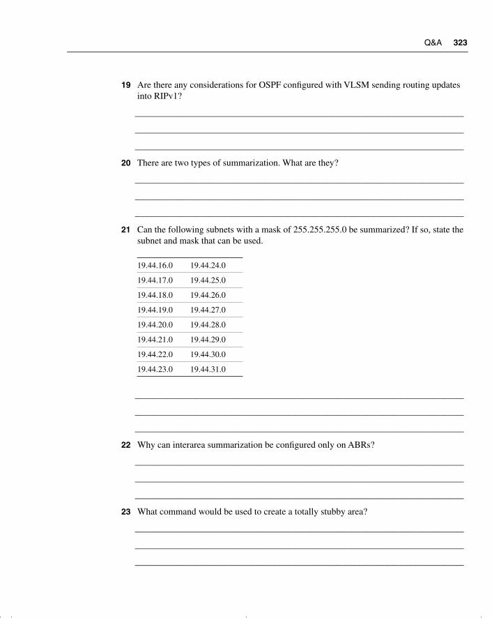
Q&A 323
19 Are there any considerations for OSPF configured with VLSM sending routing updates into RIPv1?
_______________________________________________________________________
_______________________________________________________________________
_______________________________________________________________________
20 There are two types of summarization. What are they?
_______________________________________________________________________
_______________________________________________________________________
_______________________________________________________________________
21 Can the following subnets with a mask of 255.255.255.0 be summarized? If so, state the subnet and mask that can be used.
_______________________________________________________________________
_______________________________________________________________________
_______________________________________________________________________
22 Why can interarea summarization be configured only on ABRs?
_______________________________________________________________________
_______________________________________________________________________
_______________________________________________________________________
23 What command would be used to create a totally stubby area?
_______________________________________________________________________
_______________________________________________________________________
_______________________________________________________________________
19.44.16.0 19.44.24.0
19.44.17.0 19.44.25.0
19.44.18.0 19.44.26.0
19.44.19.0 19.44.27.0
19.44.20.0 19.44.28.0
19.44.21.0 19.44.29.0
19.44.22.0 19.44.30.0
19.44.23.0 19.44.31.0
chpt_01.book Page 323 Thursday, December 21, 2000 6:22 PM
324 Chapter 6: Using OSPF Across Multiple Areas
24 What is a virtual link, and what command would be used to create it?
______________________________________________________________________
______________________________________________________________________
______________________________________________________________________
25 Where would you issue the command to summarize IP subnets? State the command that would be used.
______________________________________________________________________
______________________________________________________________________
______________________________________________________________________
26 How would you summarize external routes before injecting them into the OSPF domain?
______________________________________________________________________
______________________________________________________________________
______________________________________________________________________
chpt_01.book Page 324 Thursday, December 21, 2000 6:22 PM
Scenario 6-1 325
Scenarios
The following scenarios and questions are designed to draw together the content of the chapter and to exercise your understanding of the concepts. There is not necessarily a right answer. The thought process and practice in manipulating the concepts is the goal of this section. The answers to the scenario questions are found at the end of this chapter.
Scenario 6-1Refer to Figure 6-14, and design the addressing scheme for the network. After this is designed, write the configuration for the central router.
Ensure that you include the following:
1 Address the network using the private network 10.0.0.0. Design the addressing scheme so that it allows for the summarization of addresses between areas. Show the summarization that you allocate, and explain your reasons for your choices.
Area 0 is using a prefix of 28 bits within the area.
Area 2 is using a prefix of 22 bits within the area.
Area 3 is using a prefix of 24 bits within the area.
Area 4 is using a prefix of 30 bits for the serial connections. It is using a 28-bit prefix for the connections to the Ethernet routers. Do not include the subnets attached to the LANs in Area 4.
2 Issue the commands for the main router Figure 6-14 to configure the following:
— The router ID
— The network commands to place the appropriate interfaces into the correct areas
— The configuration of the totally stubby area (Area 4)
— The configuration of the stub (Area 4)
— Summarization between areas
— The election of the central router as designated router, where appropriate
chpt_01.book Page 325 Thursday, December 21, 2000 6:22 PM
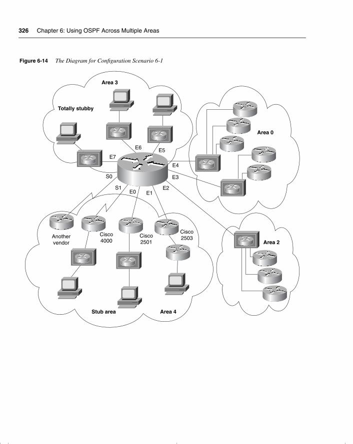
326 Chapter 6: Using OSPF Across Multiple Areas
Figure 6-14 The Diagram for Configuration Scenario 6-1
Area 3
Totally stubby
S0
S1E0 E1
E2
E3
E4
E5E6
E7
Area 0
Area 2
Area 4Stub area
Anothervendor
Cisco2501
Cisco2503
Cisco4000
chpt_01.book Page 326 Thursday, December 21, 2000 6:22 PM
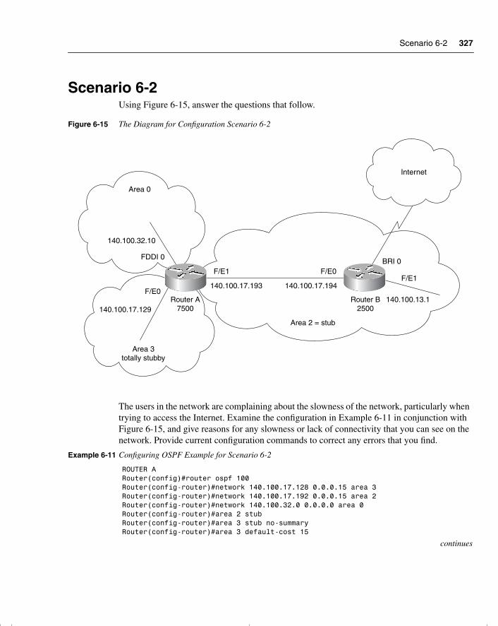
Scenario 6-2 327
Scenario 6-2Using Figure 6-15, answer the questions that follow.
Figure 6-15 The Diagram for Configuration Scenario 6-2
The users in the network are complaining about the slowness of the network, particularly when trying to access the Internet. Examine the configuration in Example 6-11 in conjunction with Figure 6-15, and give reasons for any slowness or lack of connectivity that you can see on the network. Provide current configuration commands to correct any errors that you find.
Example 6-11 Configuring OSPF Example for Scenario 6-2
ROUTER ARouter(config)#router ospf 100Router(config-router)#network 140.100.17.128 0.0.0.15 area 3Router(config-router)#network 140.100.17.192 0.0.0.15 area 2Router(config-router)#network 140.100.32.0 0.0.0.0 area 0Router(config-router)#area 2 stubRouter(config-router)#area 3 stub no-summaryRouter(config-router)#area 3 default-cost 15
continues
BRI 0F/E1
F/E1F/E0
F/E0140.100.13.1Router B
2500
140.100.17.194140.100.17.193
Area 2 = stub
Area 0
140.100.32.10
FDDI 0
Router A7500140.100.17.129
Area 3totally stubby
Internet
chpt_01.book Page 327 Thursday, December 21, 2000 6:22 PM
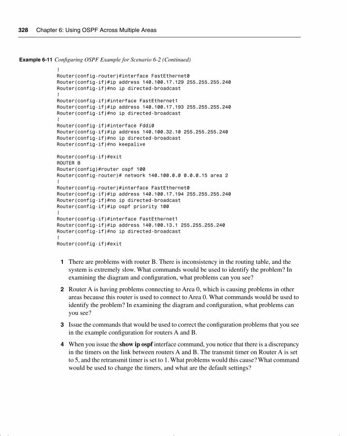
328 Chapter 6: Using OSPF Across Multiple Areas
1 There are problems with router B. There is inconsistency in the routing table, and the system is extremely slow. What commands would be used to identify the problem? In examining the diagram and configuration, what problems can you see?
2 Router A is having problems connecting to Area 0, which is causing problems in other areas because this router is used to connect to Area 0. What commands would be used to identify the problem? In examining the diagram and configuration, what problems can you see?
3 Issue the commands that would be used to correct the configuration problems that you see in the example configuration for routers A and B.
4 When you issue the show ip ospf interface command, you notice that there is a discrepancy in the timers on the link between routers A and B. The transmit timer on Router A is set to 5, and the retransmit timer is set to 1. What problems would this cause? What command would be used to change the timers, and what are the default settings?
! Router(config-router)#interface FastEthernet0Router(config-if)#ip address 140.100.17.129 255.255.255.240Router(config-if)#no ip directed-broadcast!Router(config-if)#interface FastEthernet1Router(config-if)#ip address 140.100.17.193 255.255.255.240Router(config-if)#no ip directed-broadcast!Router(config-if)#interface Fddi0Router(config-if)#ip address 140.100.32.10 255.255.255.240Router(config-if)#no ip directed-broadcastRouter(config-if)#no keepalive
Router(config-if)#exitROUTER BRouter(config)#router ospf 100Router(config-router)# network 140.100.0.0 0.0.0.15 area 2!Router(config-router)#interface FastEthernet0Router(config-if)#ip address 140.100.17.194 255.255.255.240Router(config-if)#no ip directed-broadcastRouter(config-if)#ip ospf priority 100!Router(config-if)#interface FastEthernet1Router(config-if)#ip address 140.100.13.1 255.255.255.240Router(config-if)#no ip directed-broadcast!Router(config-if)#exit
Example 6-11 Configuring OSPF Example for Scenario 6-2 (Continued)
chpt_01.book Page 328 Thursday, December 21, 2000 6:22 PM
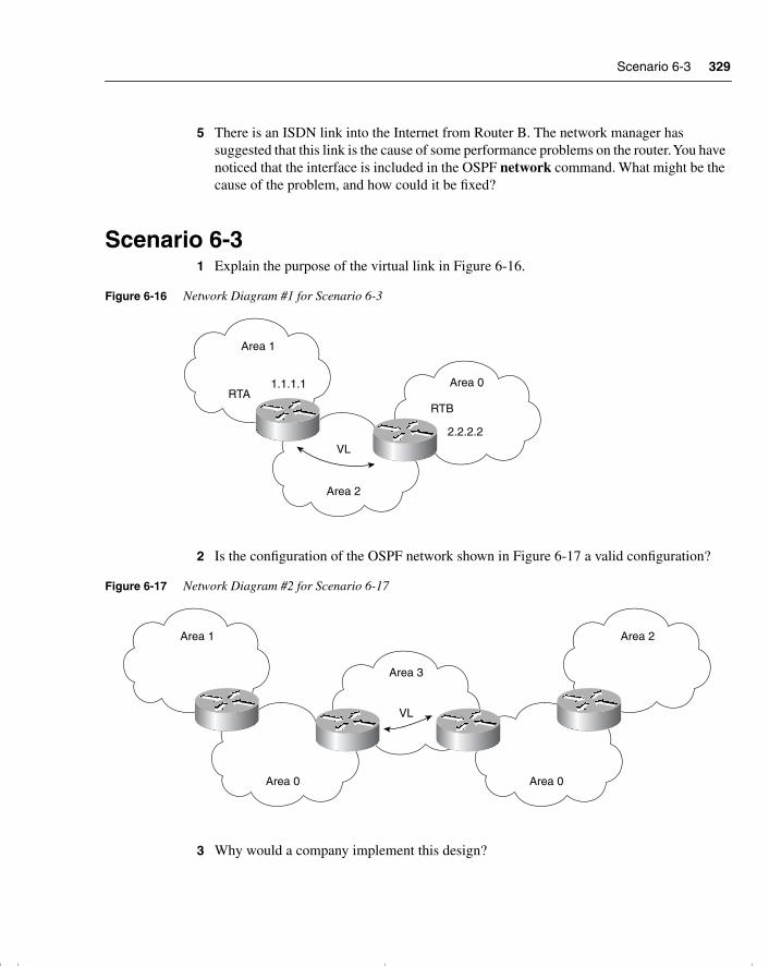
Scenario 6-3 329
5 There is an ISDN link into the Internet from Router B. The network manager has suggested that this link is the cause of some performance problems on the router. You have noticed that the interface is included in the OSPF network command. What might be the cause of the problem, and how could it be fixed?
Scenario 6-31 Explain the purpose of the virtual link in Figure 6-16.
Figure 6-16 Network Diagram #1 for Scenario 6-3
2 Is the configuration of the OSPF network shown in Figure 6-17 a valid configuration?
Figure 6-17 Network Diagram #2 for Scenario 6-17
3 Why would a company implement this design?
Area 1
Area 2
Area 0RTA
1.1.1.1
VL
RTB
2.2.2.2
Area 1
Area 0 Area 0
Area 3
Area 2
VL
chpt_01.book Page 329 Thursday, December 21, 2000 6:22 PM
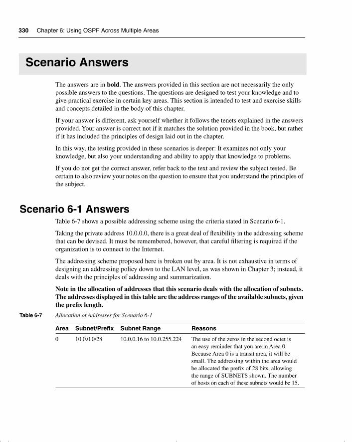
330 Chapter 6: Using OSPF Across Multiple Areas
Scenario Answers
The answers are in bold. The answers provided in this section are not necessarily the only possible answers to the questions. The questions are designed to test your knowledge and to give practical exercise in certain key areas. This section is intended to test and exercise skills and concepts detailed in the body of this chapter.
If your answer is different, ask yourself whether it follows the tenets explained in the answers provided. Your answer is correct not if it matches the solution provided in the book, but rather if it has included the principles of design laid out in the chapter.
In this way, the testing provided in these scenarios is deeper: It examines not only your knowledge, but also your understanding and ability to apply that knowledge to problems.
If you do not get the correct answer, refer back to the text and review the subject tested. Be certain to also review your notes on the question to ensure that you understand the principles of the subject.
Scenario 6-1 AnswersTable 6-7 shows a possible addressing scheme using the criteria stated in Scenario 6-1.
Taking the private address 10.0.0.0, there is a great deal of flexibility in the addressing scheme that can be devised. It must be remembered, however, that careful filtering is required if the organization is to connect to the Internet.
The addressing scheme proposed here is broken out by area. It is not exhaustive in terms of designing an addressing policy down to the LAN level, as was shown in Chapter 3; instead, it deals with the principles of addressing and summarization.
Note in the allocation of addresses that this scenario deals with the allocation of subnets. The addresses displayed in this table are the address ranges of the available subnets, given the prefix length.
Table 6-7 Allocation of Addresses for Scenario 6-1
Area Subnet/Prefix Subnet Range Reasons
0 10.0.0.0/28 10.0.0.16 to 10.0.255.224 The use of the zeros in the second octet is an easy reminder that you are in Area 0. Because Area 0 is a transit area, it will be small. The addressing within the area would be allocated the prefix of 28 bits, allowing the range of SUBNETS shown. The number of hosts on each of these subnets would be 15.
chpt_01.book Page 330 Thursday, December 21, 2000 6:22 PM
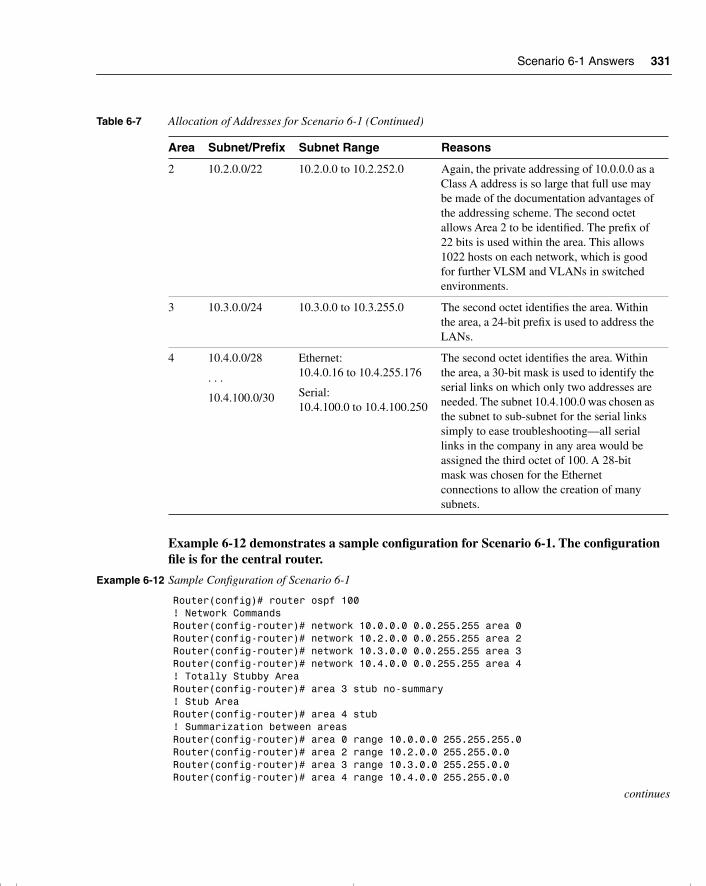
Scenario 6-1 Answers 331
Example 6-12 demonstrates a sample configuration for Scenario 6-1. The configuration file is for the central router.
2 10.2.0.0/22 10.2.0.0 to 10.2.252.0 Again, the private addressing of 10.0.0.0 as a Class A address is so large that full use may be made of the documentation advantages of the addressing scheme. The second octet allows Area 2 to be identified. The prefix of 22 bits is used within the area. This allows 1022 hosts on each network, which is good for further VLSM and VLANs in switched environments.
3 10.3.0.0/24 10.3.0.0 to 10.3.255.0 The second octet identifies the area. Within the area, a 24-bit prefix is used to address the LANs.
4 10.4.0.0/28
. . .
10.4.100.0/30
Ethernet:10.4.0.16 to 10.4.255.176
Serial:10.4.100.0 to 10.4.100.250
The second octet identifies the area. Within the area, a 30-bit mask is used to identify the serial links on which only two addresses are needed. The subnet 10.4.100.0 was chosen as the subnet to sub-subnet for the serial links simply to ease troubleshooting—all serial links in the company in any area would be assigned the third octet of 100. A 28-bit mask was chosen for the Ethernet connections to allow the creation of many subnets.
Example 6-12 Sample Configuration of Scenario 6-1
Router(config)# router ospf 100! Network CommandsRouter(config-router)# network 10.0.0.0 0.0.255.255 area 0Router(config-router)# network 10.2.0.0 0.0.255.255 area 2Router(config-router)# network 10.3.0.0 0.0.255.255 area 3Router(config-router)# network 10.4.0.0 0.0.255.255 area 4! Totally Stubby AreaRouter(config-router)# area 3 stub no-summary! Stub AreaRouter(config-router)# area 4 stub! Summarization between areasRouter(config-router)# area 0 range 10.0.0.0 255.255.255.0Router(config-router)# area 2 range 10.2.0.0 255.255.0.0Router(config-router)# area 3 range 10.3.0.0 255.255.0.0Router(config-router)# area 4 range 10.4.0.0 255.255.0.0
continues
Table 6-7 Allocation of Addresses for Scenario 6-1 (Continued)
Area Subnet/Prefix Subnet Range Reasons
chpt_01.book Page 331 Thursday, December 21, 2000 6:22 PM
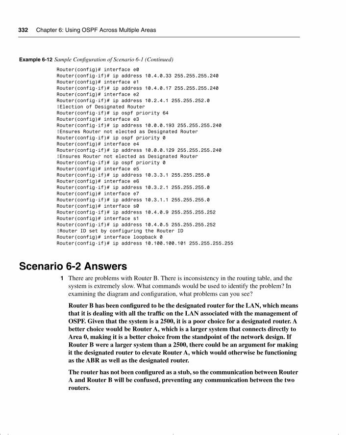
332 Chapter 6: Using OSPF Across Multiple Areas
Scenario 6-2 Answers1 There are problems with Router B. There is inconsistency in the routing table, and the
system is extremely slow. What commands would be used to identify the problem? In examining the diagram and configuration, what problems can you see?
Router B has been configured to be the designated router for the LAN, which means that it is dealing with all the traffic on the LAN associated with the management of OSPF. Given that the system is a 2500, it is a poor choice for a designated router. A better choice would be Router A, which is a larger system that connects directly to Area 0, making it is a better choice from the standpoint of the network design. If Router B were a larger system than a 2500, there could be an argument for making it the designated router to elevate Router A, which would otherwise be functioning as the ABR as well as the designated router.
The router has not been configured as a stub, so the communication between Router A and Router B will be confused, preventing any communication between the two routers.
Router(config)# interface e0Router(config-if)# ip address 10.4.0.33 255.255.255.240Router(config)# interface e1Router(config-if)# ip address 10.4.0.17 255.255.255.240Router(config)# interface e2Router(config-if)# ip address 10.2.4.1 255.255.252.0!Election of Designated RouterRouter(config-if)# ip ospf priority 64Router(config)# interface e3Router(config-if)# ip address 10.0.0.193 255.255.255.240!Ensures Router not elected as Designated RouterRouter(config-if)# ip ospf priority 0Router(config)# interface e4Router(config-if)# ip address 10.0.0.129 255.255.255.240!Ensures Router not elected as Designated RouterRouter(config-if)# ip ospf priority 0Router(config)# interface e5Router(config-if)# ip address 10.3.3.1 255.255.255.0Router(config)# interface e6Router(config-if)# ip address 10.3.2.1 255.255.255.0Router(config)# interface e7Router(config-if)# ip address 10.3.1.1 255.255.255.0Router(config)# interface s0Router(config-if)# ip address 10.4.0.9 255.255.255.252Router(config)# interface s1Router(config-if)# ip address 10.4.0.5 255.255.255.252!Router ID set by configuring the Router IDRouter(config)# interface loopback 0Router(config-if)# ip address 10.100.100.101 255.255.255.255
Example 6-12 Sample Configuration of Scenario 6-1 (Continued)
chpt_01.book Page 332 Thursday, December 21, 2000 6:22 PM
Scenario 6-2 Answers 333
2 Router A is having problems connecting to Area 0, which is causing problems in other areas because this router is used to connect to Area 0. What commands would be used to identify the problem? In examining the diagram and configuration, what problems can you see?
Router A is configured incorrectly. The command that would show the problem would be either show ip route, show ip protocols, or show ip ospf database. The lack of LSA traffic would indicate a configuration problem. When examining the configuration, you would see that the mask on the configuration of the network command for Area 0 is wrong. Therefore, there will be no communication of OSPF LSAs between the areas.
3 Issue the commands that would be used to correct the configuration problems that you see in the example configuration for routers A and B.
The commands that would solve these problems are as follows:
On Router A:
router ospf 100network 140.100.32.0 0.0.0.15 area 0interface fastethernet 1no ip ospf cost 10ip ospf priority 100
On Router B:
router ospf 200network 140.100.13.0 0.0.0.15 area 2area 2 stubinterface FastEthernet0no ip ospf priority 100
4 When you issue the show ip ospf interface command, you notice that there is a discrepancy in the timers on the link between routers A and B. The transmit timer on Router A is set to 5, and the retransmit timer is set to 1. What problems would this cause? What command would be used to change the timers, and what are the default settings?
The default setting for the transmit timer is set to 1 second, and the retransmit timer is set to 5 seconds. The transmit timer determines the estimated number of seconds that it takes to send a LSA to a neighbor. The retransmit timer states the number of seconds to wait for an acknowledgment before retransmitting an LSA.
If the transmit timer is not smaller than the retransmit timer, the interface retransmits in the belief that the other side did not receive the LSA. This leads to excess traffic, confusion in the topology database, and the possibility of flapping links. To correct the settings, issue the following subinterface commands:
ip ospf retransmit-interval seconds ip ospf transmit-delay seconds
chpt_01.book Page 333 Thursday, December 21, 2000 6:22 PM
334 Chapter 6: Using OSPF Across Multiple Areas
5 There is an ISDN link into the Internet from Router B. The network manager has suggested that this link is the cause of some performance problems on the router. You have noticed that the interface is included in the OSPF network command. What might be the cause of the problem, and how could it be fixed?
If the ISDN interface is configured for dial-on-demand routing (DDR) and is also included in OSPF network commands, you may find that the link that the DDR process establishes will cause the routing updates to be propagated throughout the network, causing additional CPU utilization on the routers and flooding of packets throughout the network. The solution is to ensure that the interface is not included in the network command to the OSPF process. A more important problem is that Router B is in a stub area and will not track external routes. Router B cannot connect to the Internet as an ASBR because it will not propagate the Type 5 LSAs. The BRI interface cannot partake in the OSPF network. Therefore, the network will not be slow; it will be down.
Scenario 6-3 Answers1 Explain the purpose of the virtual link in Figure 6-16.
In this example, Area 1 does not have a direct physical connection into Area 0. A virtual link must be configured between RTA and RTB. Area 2 is to be used as a transit area, and RTB is the entry point into Area 0. This way, RTA and Area 1 will have a logical connection to the backbone.
2 Is the configuration of the OSPF network shown in Figure 6-17 a valid configuration?
Yes, the configuration is a valid one.
3 Why would a company implement this design?
OSPF allows for linking discontinuous parts of the backbone using a virtual link. In some cases, different Area 0s need to be linked together. This can occur, for example, if a company is trying to merge two separate OSPF networks into one network with a common Area 0. In other instances, virtual links are added for redundancy in case some router failure causes the backbone to be split in two. Whatever the reason may be, a virtual link can be configured between separate ABRs that touch Area 0 from each side and that have a common area.
chpt_01.book Page 334 Thursday, December 21, 2000 6:22 PM

chpt_01.book Page 335 Thursday, December 21, 2000 6:22 PM
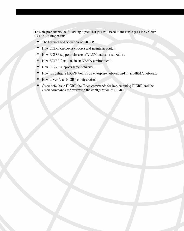
This chapter covers the following topics that you will need to master to pass the CCNP/CCDP Routing exam:
• The features and operation of EIGRP.
• How EIGRP discovers chooses and maintains routes.
• How EIGRP supports the use of VLSM and summarization.
• How EIGRP functions in an NBMA environment.
• How EIGRP supports large networks.
• How to configure EIGRP, both in an enterprise network and in an NBMA network.
• How to verify an EIGRP configuration.
• Cisco defaults in EIGRP, the Cisco commands for implementing EIGRP, and the Cisco commands for reviewing the configuration of EIGRP.
chpt_01.book Page 336 Thursday, December 21, 2000 6:22 PM
C H A P T E R 7Using EIGRP in Enterprise Networks
This chapter covers in detail the Enhanced Interior Gateway Routing Protocol (EIGRP). Although EIGRP has the capability of supporting IP, AppleTalk, and IPX, the Routing exam will deal with only the mechanics of the IP routing protocol. This chapter expands on
the understanding of routing within large enterprise networks that is covered in the previous chapter on OSPF within a large multiarea network.
This chapter is also broken into two topics. The first part of the chapter deals theoretically with how EIGRP works. How to implement and manage an EIGRP network is described at the end of the chapter. The operation of EIGRP, some of the options available, and design considerations are explained in this chapter, particularly in reference to scaling EIGRP and its use over a nonbroadcast multiaccess (NBMA) WAN environment. Both the network communication that the protocol uses and its configuration are explained in this chapter.
The topics in this chapter directly reflect questions on the Routing exam. EIGRP is designed for use in large networks. As a proprietary routing protocol for Cisco, it is therefore an obligatory subject in a Cisco exam on IP routing protocols. The BSCN course devotes 15 percent of its material to configuring EIGRP, and you can expect approximately 10 questions on the Routing exam to be directly related to this subject.
How to Best Use This ChapterBy taking the following steps, you can make better use of your study time:
• Keep your notes and the answers for all your work with this book in one place, for easy reference.
• When you take a quiz, write down your answers. Studies show that retention significantly increases by writing down facts and concepts, even if you never look at the information again.
• Use the diagram in Figure 7-1 to guide you to the next step.
chpt_01.book Page 337 Thursday, December 21, 2000 6:22 PM
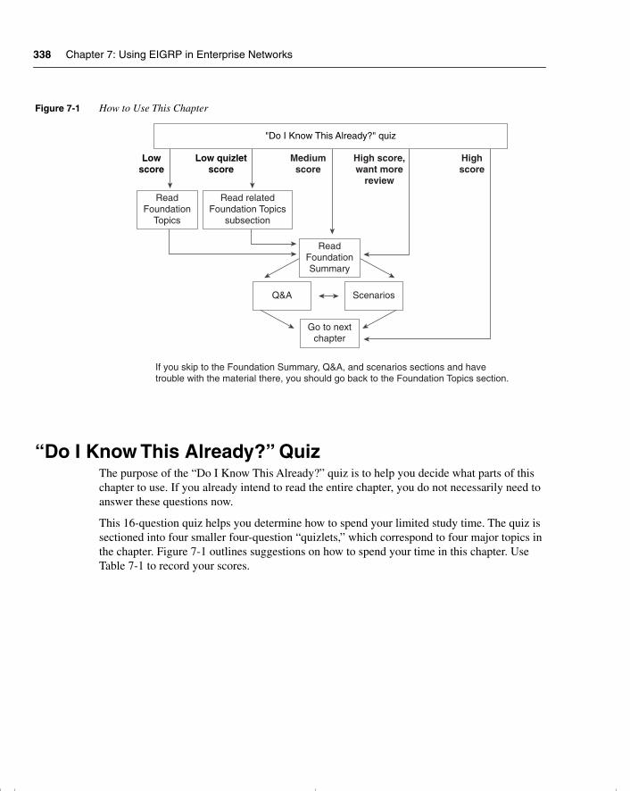
338 Chapter 7: Using EIGRP in Enterprise Networks
Figure 7-1 How to Use This Chapter
“Do I Know This Already?” QuizThe purpose of the “Do I Know This Already?” quiz is to help you decide what parts of this chapter to use. If you already intend to read the entire chapter, you do not necessarily need to answer these questions now.
This 16-question quiz helps you determine how to spend your limited study time. The quiz is sectioned into four smaller four-question “quizlets,” which correspond to four major topics in the chapter. Figure 7-1 outlines suggestions on how to spend your time in this chapter. Use Table 7-1 to record your scores.
Lowscore
Low quizletscore
Mediumscore
High score,want more
review
Highscore
"Do I Know This Already?" quiz
ReadFoundation
Topics
Read relatedFoundation Topics
subsection
ReadFoundationSummary
Q&A Scenarios
Go to nextchapter
If you skip to the Foundation Summary, Q&A, and scenarios sections and havetrouble with the material there, you should go back to the Foundation Topics section.
chpt_01.book Page 338 Thursday, December 21, 2000 6:22 PM
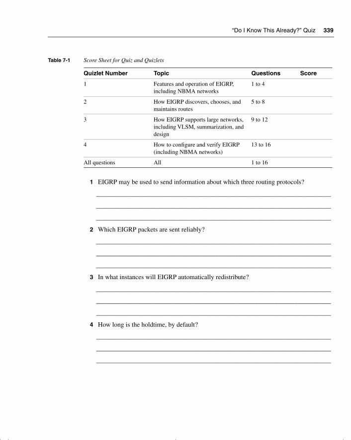
“Do I Know This Already?” Quiz 339
1 EIGRP may be used to send information about which three routing protocols?
_______________________________________________________________________
_______________________________________________________________________
_______________________________________________________________________
2 Which EIGRP packets are sent reliably?
_______________________________________________________________________
_______________________________________________________________________
_______________________________________________________________________
3 In what instances will EIGRP automatically redistribute?
_______________________________________________________________________
_______________________________________________________________________
_______________________________________________________________________
4 How long is the holdtime, by default?
_______________________________________________________________________
_______________________________________________________________________
_______________________________________________________________________
Table 7-1 Score Sheet for Quiz and Quizlets
Quizlet Number Topic Questions Score
1 Features and operation of EIGRP, including NBMA networks
1 to 4
2 How EIGRP discovers, chooses, and maintains routes
5 to 8
3 How EIGRP supports large networks, including VLSM, summarization, and design
9 to 12
4 How to configure and verify EIGRP (including NBMA networks)
13 to 16
All questions All 1 to 16
chpt_01.book Page 339 Thursday, December 21, 2000 6:22 PM
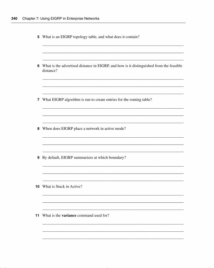
340 Chapter 7: Using EIGRP in Enterprise Networks
5 What is an EIGRP topology table, and what does it contain?
______________________________________________________________________
______________________________________________________________________
______________________________________________________________________
6 What is the advertised distance in EIGRP, and how is it distinguished from the feasible distance?
______________________________________________________________________
______________________________________________________________________
______________________________________________________________________
7 What EIGRP algorithm is run to create entries for the routing table?
______________________________________________________________________
______________________________________________________________________
______________________________________________________________________
8 When does EIGRP place a network in active mode?
______________________________________________________________________
______________________________________________________________________
______________________________________________________________________
9 By default, EIGRP summarizes at which boundary?
______________________________________________________________________
______________________________________________________________________
______________________________________________________________________
10 What is Stuck in Active?
______________________________________________________________________
______________________________________________________________________
______________________________________________________________________
11 What is the variance command used for?
______________________________________________________________________
______________________________________________________________________
______________________________________________________________________
chpt_01.book Page 340 Thursday, December 21, 2000 6:22 PM
“Do I Know This Already?” Quiz 341
12 State two factors that influence EIGRP scalability.
_______________________________________________________________________
_______________________________________________________________________
_______________________________________________________________________
13 What command is used to display which routes are in passive or active mode?
_______________________________________________________________________
_______________________________________________________________________
_______________________________________________________________________
14 What command is used in EIGRP to perform manual summarization?
_______________________________________________________________________
_______________________________________________________________________
_______________________________________________________________________
15 For Frame Relay, when would you configure the physical interface (as opposed to a subinterface) with the bandwidth command?
_______________________________________________________________________
_______________________________________________________________________
_______________________________________________________________________
16 Which command is used to display all types of EIGRP packets that are both received and sent by a router?
_______________________________________________________________________
_______________________________________________________________________
_______________________________________________________________________
The answers to this quiz are found in Appendix A, “Answers to Quiz Questions.” The suggested choices for your next step are as follows:
• 2 or less on any quizlet—Review the appropriate sections of the “Foundation Topics” portion of this chapter, based on Table 7-1. Then move on to the “Foundation Summary” section, the “Q&A” section, and the “Scenarios” at the end of the chapter.
• 8 or less overall score—Read the entire chapter. This includes the “Foundation Topics” and “Foundation Summary” sections, the “Q&A” section, and the “Scenarios” at the end of the chapter.
chpt_01.book Page 341 Thursday, December 21, 2000 6:22 PM

342 Chapter 7: Using EIGRP in Enterprise Networks
• 9 to 12 overall score—Begin with the “Foundation Summary” section, and then go to the “Q&A” section and the “Scenarios” at the end of the chapter. If you have trouble with these exercises, read the appropriate sections in “Foundation Topics.”
• 13 or more overall score—If you want more review on these topics, skip to the “Foundation Summary” section, and then go to the “Q&A” section and the “Scenarios” at the end of the chapter. Otherwise, move to the next chapter.
chpt_01.book Page 342 Thursday, December 21, 2000 6:22 PM
Introduction: EIGRP in an Enterprise Network 343
Foundation Topics
Introduction: EIGRP in an Enterprise NetworkEIGRP is an enhanced version of IGRP, hence the name. It uses the same distance vector technology. The changes were effected in the convergence properties and the operating efficiency of the protocol. It has some characteristics similar to those of a link-state routing protocol. Therefore, it is sometimes referred to as a hybrid routing protocol, although Cisco calls it an advanced distance vector protocol. It is an efficient, although proprietary, solution to networking large environments as it scales well. Its ability to scale is, like OSPF, dependent on the design of the network.
Case StudyThe company Gargantuan, Inc., is a large multinational. It has its main offices in London, New York, San Francisco, and Tokyo. As a manufacturing company that produces cleaning products, it has plants in England, Mexico, and Japan. It has an extensive network that is running EIGRP. The network is used for local administrative purposes as well as coordinating the product movement from the manufacturing plant to the grocery store. There have been complaints during the past year about poor response times on the network. This has reached critical proportions because the problems are no longer simply irritations for the users, but they are now potentially devastating delays in shipping orders and transfers in electronic funds and manufacturing details.
A careful analysis of the network is required to identify the problem. A consultant has said that the entire organization needs to be readdressed and that configuration changes need to be made to the network. This involves an analysis of the network topology and data flow to appropriately design a new TCP/IP addressing scheme for the organization.
The CIO recently left, and there is very little documentation, so the network administrators have been charged with creating a network diagram and presenting some immediate solutions. This means that they have to thoroughly understand the operation of EIGRP in large environments. This chapter deals with the concepts of EIGRP and explains how it works within an enterprise. It considers design issues, particularly in reference to NBMA networks, and discusses the configuration and verification of the operation of the protocol.
EIGRP DefinedThe focus of this chapter is on how EIGRP works so that those networks can be designed to maximize efficiency and truly scale the network.
The major concern in scaling an organizational network is controlling the network overhead that is sent, in particular over slow WAN links. The less information about the network, its
chpt_01.book Page 343 Thursday, December 21, 2000 6:22 PM
344 Chapter 7: Using EIGRP in Enterprise Networks
services, and networks that need to be sent, the greater the capacity available for the data between clients and servers. Although sending less routing information relieves the network, it gives the routers less information with which to make decisions. Every designer of routing protocols and every network administrator must deal continually with this trade-off. As seen with summarization, static and default routes can lead to poor routing decisions and loss of connectivity.
OSPF was the first protocol to attempt to address these problems. Alternatives to OSPF that offer the capability to scale to the size of modern networks are few. Static routing is one possibility, but it demands so much from the network administrator that it would never scale. IGRP offers another alternative; as a proprietary distance vector protocol, IGRP has solved many of the problems. However, it does face some issues with regard to scaling because of the inherent nature of distance vector. Although still distance vector and proprietary, EIGRP addresses many of the problems related to scaling the network that IGRP never anticipated.
This chapter discusses EIGRP. As a proprietary routing protocol, EIGRP can solve many problems seen in standards-based protocols that have to please all of the devices all of the time.
Operation of EIGRPEIGRP is a revised and improved version of IGRP. Its goal is to solve the scaling limitations that IGRP faces, using the distance vector technology from which it grew. EIGRP increases the potential growth of a network by reducing the convergence time. This is achieved by the following:
• The Diffusing Update Algorithm (DUAL)
• Loop-free networks
• Incremental updates
• Multicast addressing for updates
• Holding information about neighbors as opposed to the entire network
These features depend on proprietary technology, which centers on local computation. The DUAL algorithm diffuses this computation over multiple routers, with each router responsible for its own small calculation and making requests of neighboring routers when necessary. A full understanding of the concepts and operation of EIGRP will aid you in the design, implementation, and maintenance of EIGRP networks, and will definitely help you pass an exam on the subject.
The main concepts of EIGRP are as follows:
• Advanced distance vector
• Loop-free routing tables
• Support for different topologies
chpt_01.book Page 344 Thursday, December 21, 2000 6:22 PM
Operation of EIGRP 345
• Rapid convergence
• Reduced bandwidth use
• Use of a composite metric (bandwidth and delay as the default)
• Unequal load balancing
• Neighbor discovery
• DUAL
• Successors, the selection process for a feasible successor
• Passive and active routes
• Protocol independence at Layer 3, allowing support for IP, AppleTalk, and IPX
• Reliable sending of routing updates
• VLSM, which allows efficient addressing, discontiguous networks, and the use of classless networks
• Manual summarization
• Compatibility with IGRP
• Easy-to-configure nature
• Fewer design constraints than OSPF
How EIGRP WorksCisco identifies four main components of EIGRP:
• Protocol-dependent modules
• Reliable Transport Protocol
• Neighbor discovery/recovery
• DUAL
These components are discussed in this section. However, to understand how EIGRP works, there must be some familiarity with the terminology. Table 7-2 defines the main concepts and gives a brief synopsis of each term.
chpt_01.book Page 345 Thursday, December 21, 2000 6:22 PM
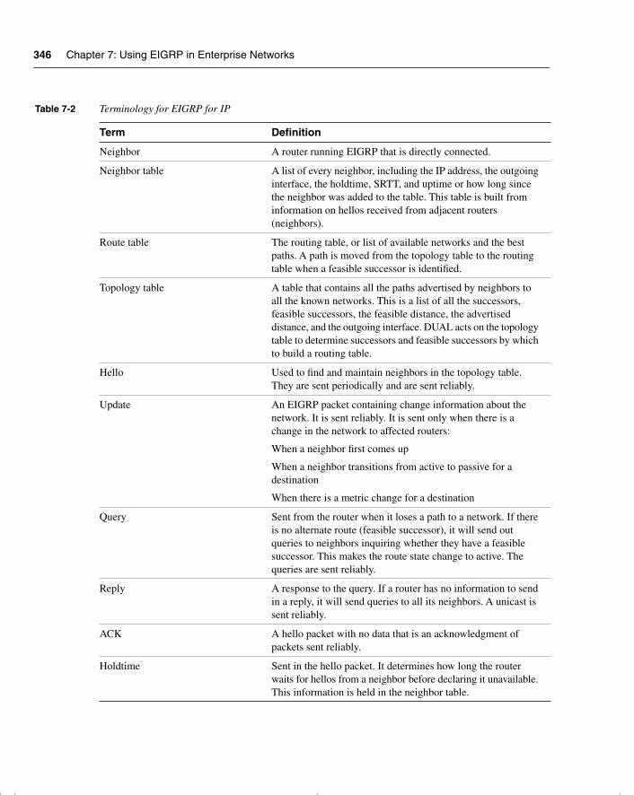
346 Chapter 7: Using EIGRP in Enterprise Networks
Table 7-2 Terminology for EIGRP for IP
Term Definition
Neighbor A router running EIGRP that is directly connected.
Neighbor table A list of every neighbor, including the IP address, the outgoing interface, the holdtime, SRTT, and uptime or how long since the neighbor was added to the table. This table is built from information on hellos received from adjacent routers (neighbors).
Route table The routing table, or list of available networks and the best paths. A path is moved from the topology table to the routing table when a feasible successor is identified.
Topology table A table that contains all the paths advertised by neighbors to all the known networks. This is a list of all the successors, feasible successors, the feasible distance, the advertised distance, and the outgoing interface. DUAL acts on the topology table to determine successors and feasible successors by which to build a routing table.
Hello Used to find and maintain neighbors in the topology table. They are sent periodically and are sent reliably.
Update An EIGRP packet containing change information about the network. It is sent reliably. It is sent only when there is a change in the network to affected routers:
When a neighbor first comes up
When a neighbor transitions from active to passive for a destination
When there is a metric change for a destination
Query Sent from the router when it loses a path to a network. If there is no alternate route (feasible successor), it will send out queries to neighbors inquiring whether they have a feasible successor. This makes the route state change to active. The queries are sent reliably.
Reply A response to the query. If a router has no information to send in a reply, it will send queries to all its neighbors. A unicast is sent reliably.
ACK A hello packet with no data that is an acknowledgment of packets sent reliably.
Holdtime Sent in the hello packet. It determines how long the router waits for hellos from a neighbor before declaring it unavailable. This information is held in the neighbor table.
chpt_01.book Page 346 Thursday, December 21, 2000 6:22 PM
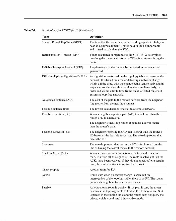
Operation of EIGRP 347
Smooth Round Trip Time (SRTT) The time that the router waits after sending a packet reliably to hear an acknowledgment. This is held in the neighbor table and is used to calculate the RTO.
Retransmission Timeout (RTO) Timer calculated in reference to the SRTT. RTO determines how long the router waits for an ACK before retransmitting the packet.
Reliable Transport Protocol (RTP) Requirement that the packets be delivered in sequence and guaranteed.
Diffusing Update Algorithm (DUAL) An algorithm performed on the topology table to converge the network. It is based on a router detecting a network change within a finite time, with the change being sent reliably and in sequence. As the algorithm is calculated simultaneously, in order and within a finite time frame on all affected routers, it ensures a loop-free network.
Advertised distance (AD) The cost of the path to the remote network from the neighbor (the metric from the next-hop router).
Feasible distance (FD) The lowest-cost distance (metric) to a remote network.
Feasible condition (FC) When a neighbor reports a path (AD) that is lower than the router’s FD to a network.
The neighbor’s (next-hop router’s) path has a lower metric than the router’s path.
Feasible successor (FS) The neighbor reporting the AD that is lower than the router’s FD becomes the feasible successor. The next-hop router that meets the FC.
Successor The next-hop router that passes the FC. It is chosen from the FSs as having the lowest metric to the remote network.
Stuck in Active (SIA) When a router has sent out network packets and is waiting for ACKs from all its neighbors. The route is active until all the ACKs have been received, if they do not appear after a certain time, the router is Stuck in Active for the route.
Query scoping Another term for SIA.
Active Route state when a network change is seen, but on interrogation of the topology table, there is no FC. The router queries its neighbors for alternative routes.
Passive An operational route is passive. If the path is lost, the router examines the topology table to find an FS. If there is an FS, it is placed in the routing table and the router does not query the others, which would send it into active mode.
Table 7-2 Terminology for EIGRP for IP (Continued)
Term Definition
chpt_01.book Page 347 Thursday, December 21, 2000 6:22 PM
348 Chapter 7: Using EIGRP in Enterprise Networks
Even if the computation of the network is local, the router must know about the entire network. The explanation of the routing protocol will be given through the viewpoint of one router. When the network communication between the routers running EIGRP is understood, the operation of EIGRP will become clear; the concepts and terms will be placed in context. This facilitates the memorization of the subject; rote learning is no longer necessary.
The Hello ProtocolThe router sends out a small hello packet to dynamically learn of other routing devices that are in the same broadcast domain.
NOTE A broadcast domain identifies devices that are within the same Layer 2 domain. Although they may not be directly connected to the same physical cable, if they are in a switched environment, from a logical Layer 2 or Layer 3 perspective, they are on the same link. If a broadcast is sent out, all the devices within the broadcast domain will hear the message and expend resources determining whether it is addressed to them. A Layer 3 device is a broadcast firewall, in that a router does not forward broadcasts.
Becoming a NeighborThe Hello protocol uses a multicast address of 224.0.0.10, and all routers periodically send hellos. On hearing hellos, the router creates a table of its neighbors. The continued receipt of these packets maintains the neighbor table. If a hello from a known neighbor is not heard within a predetermined amount of time, as stated in the holdtime, the router will decide that the neighbor is no longer operational and will take the appropriate action. The holdtime is set at the default of three times the Hello timer. Therefore, if the router misses three hellos, the neighbor is declared dead. The Hello timer on a LAN is set to 5 seconds; the holdtime, therefore, is 15 seconds. On a WAN link, the Hello timer is 60 seconds, and the holdtime correspondingly is 180 seconds.
To become a neighbor, the following conditions must be met:
• The router must hear a hello packet or an ACK from a neighbor.
• The AS number in the packet header must be the same as that of the receiving router.
• The neighbor’s metric settings must be the same.
The Neighbor TableEach Layer 3 protocol has its own neighbor table—which makes sense because the neighbor, topology, and routing tables would differ greatly. Although all the information could be held in one table, the different EIGRP processes would all have to access the same table, which would complicate and slow down the lookup.
chpt_01.book Page 348 Thursday, December 21, 2000 6:22 PM
Operation of EIGRP 349
The Contents of the Neighbor TableThe neighbor table includes the following information:
• The address of the neighbor.
• The interface through which the neighbor’s hello was heard.
• The holdtime.
• The uptime, how long since the router first heard from the neighbor.
• The sequence number. The neighbor table tracks all the packets sent between the neighbors. It tracks both the last sequence number sent to the neighbor and the last sequence number received from the neighbor. Although the Hello protocol is a connectionless protocol, other protocols used by EIGRP are connection-oriented. The sequence number is in reference to these protocols.
• Smooth Round Trip Time (SRTT) is used to calculate the retransmission timeout (RTO). This is the time in milliseconds that it takes a packet to be sent to a neighbor and a reply to be received.
• RTO, the retransmission timeout. This states how long the router will wait on a connection-oriented protocol without an acknowledgment before retransmitting the packet. If the original packet that was unacknowledged was multicast, the retransmitted packets will be unicast.
• The number of packets in a queue. This is a means by which administrators can monitor congestion on the network.
Packets from Neighbors That Build the Topology TableAfter the router knows who its neighbors are, it is in a position to create a database of feasible successors. This view of the network is held in the topology table.
The topology table is created from updates received from the neighboring routers. The updates are exchanged between the neighbors.
Packets called replies will also update the topology table. Replies are sent in response to queries sent by the router, inquiring about suspect routes.
The queries and responses used by EIGRP for the DUAL algorithm are sent reliably as multicasts. If a router does not hear an acknowledgment within the allotted time, it retransmits the packet as a unicast. If there is no response after 16 attempts, the router marks the neighbor as dead. The window for the RTP is set as 1. The router must hear an acknowledgment from every router before it can send the next packet. The capability to send unicast retransmissions decreases the time that it takes to build the tables.
Figure 7-2 demonstrates building the neighbor table.
chpt_01.book Page 349 Thursday, December 21, 2000 6:22 PM
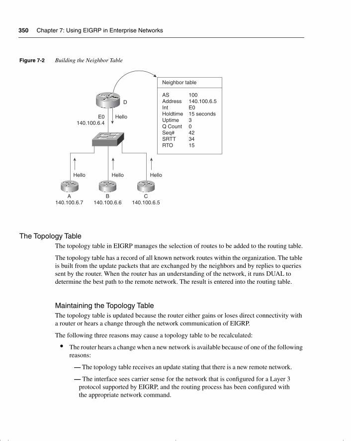
350 Chapter 7: Using EIGRP in Enterprise Networks
Figure 7-2 Building the Neighbor Table
The Topology TableThe topology table in EIGRP manages the selection of routes to be added to the routing table.
The topology table has a record of all known network routes within the organization. The table is built from the update packets that are exchanged by the neighbors and by replies to queries sent by the router. When the router has an understanding of the network, it runs DUAL to determine the best path to the remote network. The result is entered into the routing table.
Maintaining the Topology TableThe topology table is updated because the router either gains or loses direct connectivity with a router or hears a change through the network communication of EIGRP.
The following three reasons may cause a topology table to be recalculated:
• The router hears a change when a new network is available because of one of the following reasons:
— The topology table receives an update stating that there is a new remote network.
— The interface sees carrier sense for the network that is configured for a Layer 3 protocol supported by EIGRP, and the routing process has been configured with the appropriate network command.
E0140.100.6.4
D
Hello Hello Hello
Hello
A140.100.6.7
B140.100.6.6
C140.100.6.5
Neighbor table
AS 100Address 140.100.6.5Int E0Holdtime 15 secondsUptime 3Q Count 0Seq# 42SRTT 34RTO 15
chpt_01.book Page 350 Thursday, December 21, 2000 6:22 PM
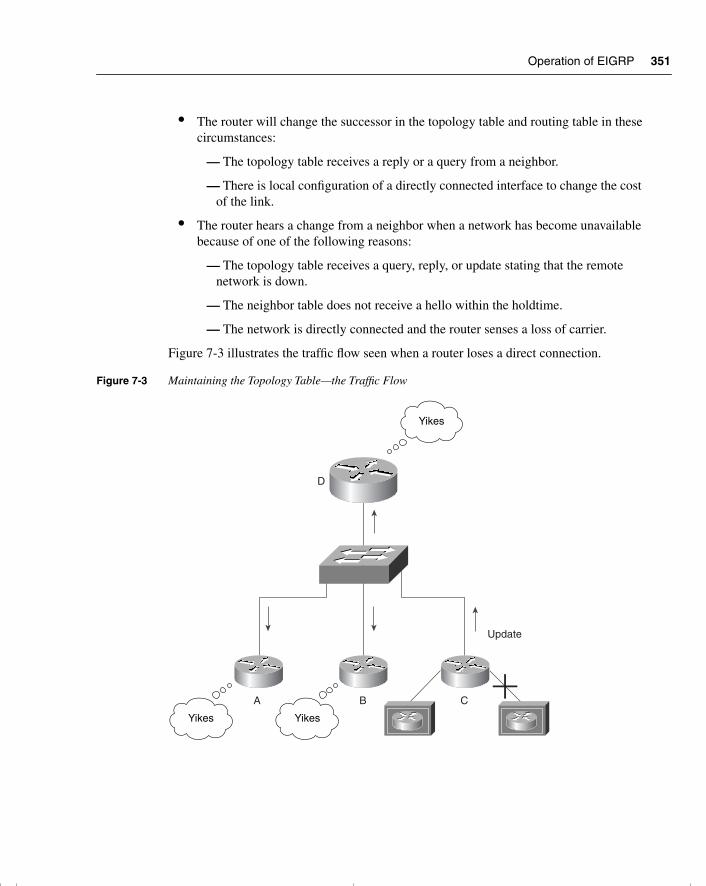
Operation of EIGRP 351
• The router will change the successor in the topology table and routing table in these circumstances:
— The topology table receives a reply or a query from a neighbor.
— There is local configuration of a directly connected interface to change the cost of the link.
• The router hears a change from a neighbor when a network has become unavailable because of one of the following reasons:
— The topology table receives a query, reply, or update stating that the remote network is down.
— The neighbor table does not receive a hello within the holdtime.
— The network is directly connected and the router senses a loss of carrier.
Figure 7-3 illustrates the traffic flow seen when a router loses a direct connection.
Figure 7-3 Maintaining the Topology Table—the Traffic Flow
D
Update
A B C
Yikes
Yikes Yikes
chpt_01.book Page 351 Thursday, December 21, 2000 6:22 PM
352 Chapter 7: Using EIGRP in Enterprise Networks
Just as the neighbor table tracks the receipt of the EIGRP packets, the topology table records the packets that have been sent by the router to the neighbors. It also identifies the status of the networks in the table. A healthy network is marked as passive; it will be labeled as active if the router is attempting to find an alternative path to the remote network that is believed to be down.
Because the routing table is built from the topology table, the topology table must have the information required by the routing table. This includes the next logical hop, or the address of the neighbor that sent the update with that network. The routing table will also calculate the metric to the remote network.
EIGRP MetricsThe metrics used in EIGRP are very similar to those of IGRP. The main difference is that the result of the calculation is held in a 32-bit field. This means that the decision can be much finer or detailed. The DUAL algorithm will use this metric to select the best path or paths to a destination. The computation is performed on paths held in the topology table to identify the best path to place into the routing table. There can be up to six paths held for one destination, and there can be three different types of paths. These three path types are described in Table 7-3.
The metric is the same composite metric used by IGRP, with the default being bandwidth and delay. Although it is possible to change the metric, this must be done only with great care and consideration to the network design. Any changes made must be effected on every router in the EIGRP AS.
The equation for the default metric used is this:
[(10000000 ÷ smallest bandwidth kbps) + delay] × 256
Table 7-4 explains the metric values.
Table 7-3 EIGRP Routing Types
Route Type Description
Internal Internal to the AS
Summary Internal paths that have been summarized
External External to the AS that have been redistributed into this EIGRP AS
chpt_01.book Page 352 Thursday, December 21, 2000 6:22 PM
Operation of EIGRP 353
The new terminology can be very confusing and is best understood in context. It is easier to remember a concept or term when the function is understood. Given the overall understanding of how EIGRP works, a consideration of the topology table and its components will help explain the detail of EIGRP operation.
The DUAL Finite-State MachineDUAL is responsible for maintenance of the topology table and the creation of the routing table. The topology table records the metric as received from the advertising router, or the next logical hop. It then adds the cost of getting to that neighbor, the one that is advertising the route.
The cost to the destination network from the advertising router, plus the cost to that router, equals the metric to the destination network from the router.
The metric or cost from the neighbor advertising the route is known as the advertised distance. The metric or cost from the router is referred to as the feasible distance. If the AD is less than the FD, then the next-hop router is downstream and there is no loop. This is fundamental to EIGRP.
Figures 7-4 and 7-5 illustrate these distances. Note that the metric shown in these figures has been simplified for the purposes of this example.
Table 7-4 EIGRP Metric Values
Metric Symbol Metric Value Description
K1 Bandwidth Selects the smallest bandwidth media between the source and destination hosts. The equation used is [10000000 ÷ bandwidth kbps] × 256.
K2 Loading Is based on the statistics held at the outgoing interface and is recorded in bits per second.
K3 Delay Is the delay calculated on the outgoing interface. The value used is the summarization of the delay on all the interfaces between the hosts.
K4 Reliability Is based on the statistics held on the outgoing interface gained from keepalives, and is exponentially averaged over 5 minutes.
K5 MTU Is the smallest MTU found configured on an interface on route. This value is included although it has not been used as part of the metric calculation.
chpt_01.book Page 353 Thursday, December 21, 2000 6:22 PM
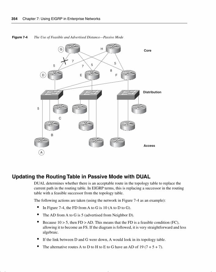
354 Chapter 7: Using EIGRP in Enterprise Networks
Figure 7-4 The Use of Feasible and Advertised Distance—Passive Mode
Updating the Routing Table in Passive Mode with DUALDUAL determines whether there is an acceptable route in the topology table to replace the current path in the routing table. In EIGRP terms, this is replacing a successor in the routing table with a feasible successor from the topology table.
The following actions are taken (using the network in Figure 7-4 as an example):
• In Figure 7-4, the FD from A to G is 10 (A to D to G).
• The AD from A to G is 5 (advertised from Neighbor D).
• Because 10 > 5, then FD > AD. This means that the FD is a feasible condition (FC), allowing it to become an FS. If the diagram is followed, it is very straightforward and less algebraic.
• If the link between D and G were down, A would look in its topology table.
• The alternative routes A to D to H to E to G have an AD of 19 (7 + 5 + 7).
G H Core
Distribution
Access
A
B
C
5
F8
ED
57
7 5 5
chpt_01.book Page 354 Thursday, December 21, 2000 6:22 PM
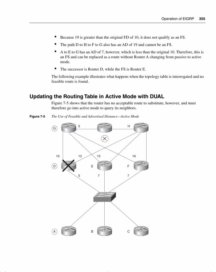
Operation of EIGRP 355
• Because 19 is greater than the original FD of 10, it does not qualify as an FS.
• The path D to H to F to G also has an AD of 19 and cannot be an FS.
• A to E to G has an AD of 7, however, which is less than the original 10. Therefore, this is an FS and can be replaced as a route without Router A changing from passive to active mode.
• The successor is Router D, while the FS is Router E.
The following example illustrates what happens when the topology table is interrogated and no feasible route is found.
Updating the Routing Table in Active Mode with DUALFigure 7-5 shows that the router has no acceptable route to substitute, however, and must therefore go into active mode to query its neighbors.
Figure 7-5 The Use of Feasible and Advertised Distance—Active Mode
5 HG
D E F
A B C
10 12 15
5 7 7
16
chpt_01.book Page 355 Thursday, December 21, 2000 6:22 PM
356 Chapter 7: Using EIGRP in Enterprise Networks
When no alternative route is found in the routing table, the following actions are taken (using the network in Figure 7-5 as an example):
• In Figure 7-5, the topology table of Router A has a path (successor) of A to D to G to X.
• The FD is 20, and the AD from Neighbor D is 15.
• When Router D dies, Router A must find an alternative path to X.
• Neighbors B, C, E, and F have ADs of 27, 27, 20, and 21, respectively.
• Because all the neighbors have an AD that is the same or greater than the successor FD, none of these are acceptable as FSs.
• Router A must go into active mode and send queries to the neighbors.
• Both Routers E and F reply with an FS because both have an AD from G of 5. Remember the equation FD > AD; their FD is 20, and 20 > 5.
• This is acceptable. The topology and routing tables will be updated, DUAL will be calculated, and the network will be returned to passive mode.
• From this information received from Routers E and F in Figure 7-5, the router selects the path through E as the best route because it has the lower cost.
• The result is placed in the routing table as the valid neighboring router. EIGRP refers to this neighboring router as a successor.
• Router F will be stored as an FS in the topology table.
The details on how EIGRP computes successors are complex, but the concept is simple.
Choosing a SuccessorTo determine whether a path to a remote network is feasible, EIGRP considers the FC of the route. Essentially, each router holds a routing table that is a list of the available networks and the best or most efficient path to each of them. The term used to describe this is the feasible distance of the successor, otherwise known as the metric for the route. The router also holds the routing table of its neighbors, referred to as the AD. If the AD is within scope, this route may be identified as an alternative route, or an FS.
A neighbor can become an FS for a route only if its AD is less than the FD. This is DUAL’s fundamental key to remaining loop-free; if a route contains a loop, the AD will be greater than the FD and therefore will fail the FC. By holding the routing tables of the neighbors, the amount of network overhead and computation is reduced. When a path to a remote network is lost, the router may well be capable of finding an alternative route with minimal fuss, computation, or network traffic. This gives the much-advertised benefit of very fast convergence.
chpt_01.book Page 356 Thursday, December 21, 2000 6:22 PM
Operation of EIGRP 357
The Topology Table FieldsThe topology table includes the following information:
• Whether the route is passive or active.
• That an update has been sent to the neighbors.
• That a query packet has been sent to the neighbors. If this field is positive, at least one route will be marked as active.
• If a query packet has been sent, another field will track whether any replies have been received from the neighbors.
• That a reply packet has been sent in response to a query packet received from a neighbor.
• The remote networks.
• The prefix or mask for the remote network.
• The metric for the remote network, the FD.
• The metric for the remote network advertised by the next logical hop, the AD.
• The next logical hop.
• The outgoing interface to be used to reach the next logical hop.
• The successors, the path to the remote network stated in hops.
Adding a Network to the Topology Table Imagine the router (Router A) that hears a new network. The administrator has plugged in another Ethernet cable to service a department that has moved into the building.
• As soon as Router A becomes aware of the new network, it starts to send Hello packets out the new interface. No one answers because this is an access router giving connectivity to the workstations and other end devices.
• There are no new entries in the neighbor table because no neighbors have responded to the Hello protocol. There is a new entry in the topology table, however, because this is a new network.
• EIGRP, sensing a change, is obliged to send an update to all its neighbors, informing them of the new network. The sent updates are tracked in the topology table and the neighbor table because the updates are connection-oriented and the acknowledgments from the neighbors must be received within a set time frame.
• Router A, having added the network to the topology table, adds the network to the routing table. The network will be marked as passive because it is operational.
chpt_01.book Page 357 Thursday, December 21, 2000 6:22 PM
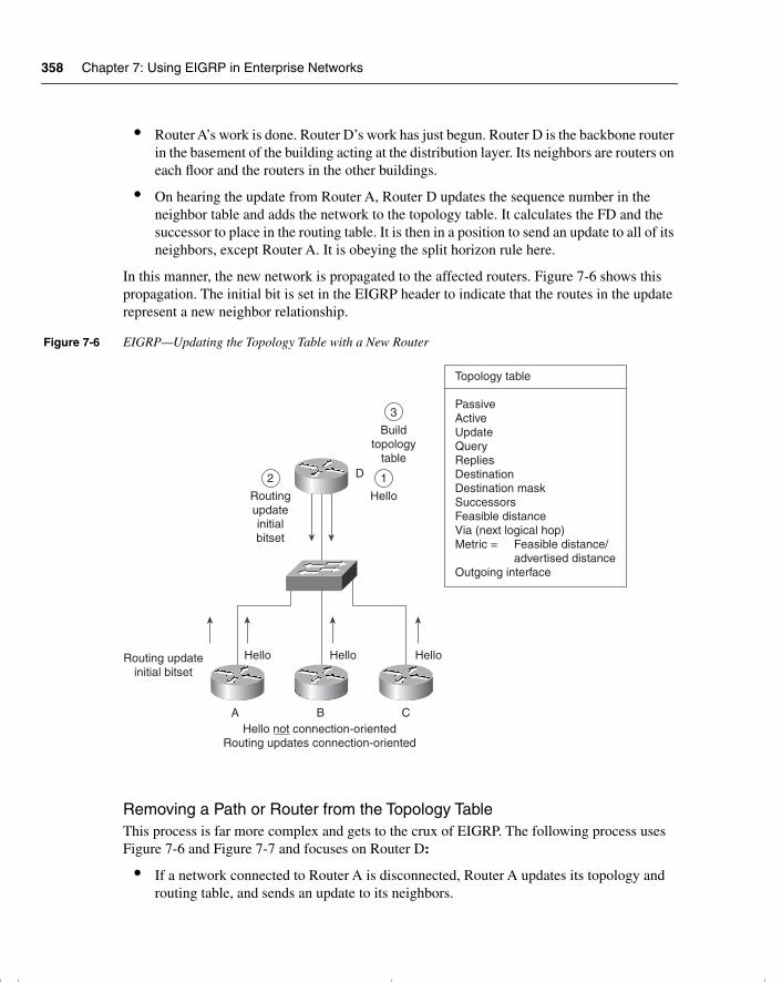
358 Chapter 7: Using EIGRP in Enterprise Networks
• Router A’s work is done. Router D’s work has just begun. Router D is the backbone router in the basement of the building acting at the distribution layer. Its neighbors are routers on each floor and the routers in the other buildings.
• On hearing the update from Router A, Router D updates the sequence number in the neighbor table and adds the network to the topology table. It calculates the FD and the successor to place in the routing table. It is then in a position to send an update to all of its neighbors, except Router A. It is obeying the split horizon rule here.
In this manner, the new network is propagated to the affected routers. Figure 7-6 shows this propagation. The initial bit is set in the EIGRP header to indicate that the routes in the update represent a new neighbor relationship.
Figure 7-6 EIGRP—Updating the Topology Table with a New Router
Removing a Path or Router from the Topology TableThis process is far more complex and gets to the crux of EIGRP. The following process uses Figure 7-6 and Figure 7-7 and focuses on Router D:
• If a network connected to Router A is disconnected, Router A updates its topology and routing table, and sends an update to its neighbors.
D
Hello Hello Hello
A B C
Topology table
PassiveActiveUpdateQueryRepliesDestinationDestination maskSuccessorsFeasible distanceVia (next logical hop)Metric = Feasible distance/
advertised distanceOutgoing interface
Hello not connection-orientedRouting updates connection-oriented
Routing updateinitial bitset
2
Routingupdateinitialbitset
3
Buildtopology
table
1
Hello
chpt_01.book Page 358 Thursday, December 21, 2000 6:22 PM
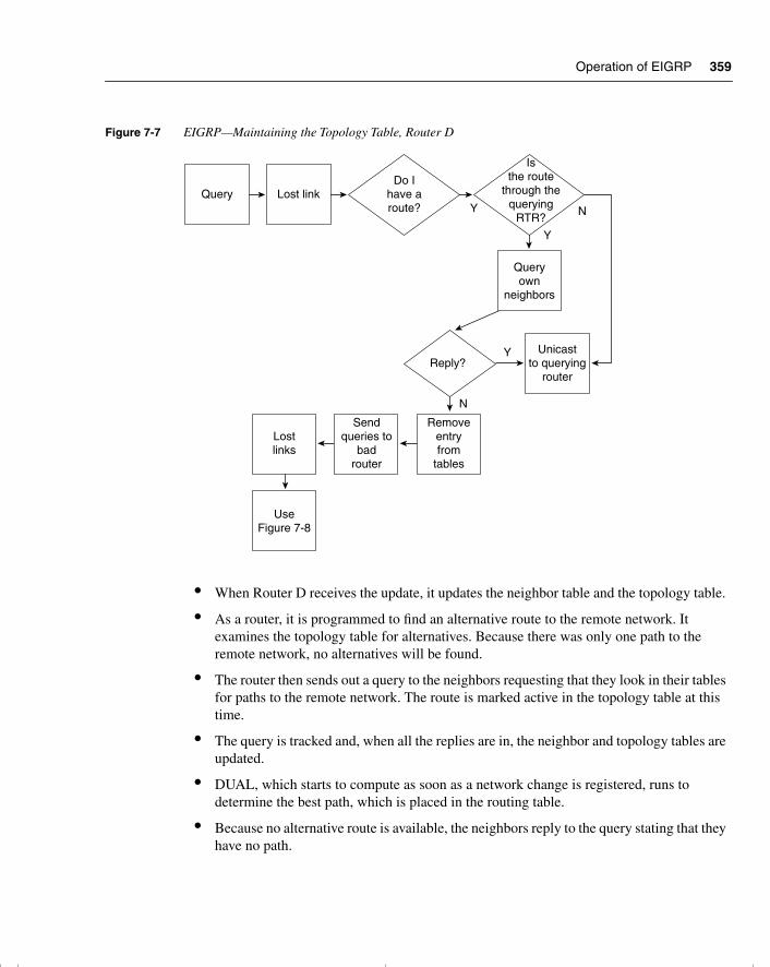
Operation of EIGRP 359
Figure 7-7 EIGRP—Maintaining the Topology Table, Router D
• When Router D receives the update, it updates the neighbor table and the topology table.
• As a router, it is programmed to find an alternative route to the remote network. It examines the topology table for alternatives. Because there was only one path to the remote network, no alternatives will be found.
• The router then sends out a query to the neighbors requesting that they look in their tables for paths to the remote network. The route is marked active in the topology table at this time.
• The query is tracked and, when all the replies are in, the neighbor and topology tables are updated.
• DUAL, which starts to compute as soon as a network change is registered, runs to determine the best path, which is placed in the routing table.
• Because no alternative route is available, the neighbors reply to the query stating that they have no path.
Query Lost linkDo I
have aroute?
Isthe route
through thequerying
RTR?
Queryown
neighbors
Reply?
Y N
Y
Y
N
Unicastto querying
router
Lostlinks
Sendqueries to
badrouter
Removeentryfrom
tables
UseFigure 7-8
chpt_01.book Page 359 Thursday, December 21, 2000 6:22 PM
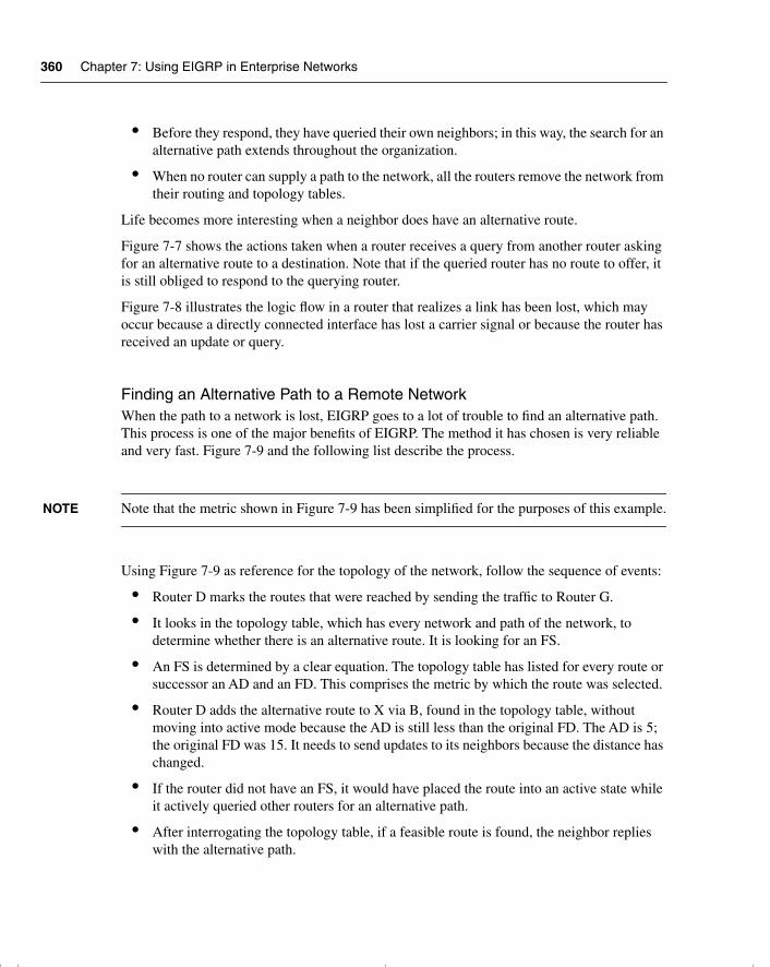
360 Chapter 7: Using EIGRP in Enterprise Networks
• Before they respond, they have queried their own neighbors; in this way, the search for an alternative path extends throughout the organization.
• When no router can supply a path to the network, all the routers remove the network from their routing and topology tables.
Life becomes more interesting when a neighbor does have an alternative route.
Figure 7-7 shows the actions taken when a router receives a query from another router asking for an alternative route to a destination. Note that if the queried router has no route to offer, it is still obliged to respond to the querying router.
Figure 7-8 illustrates the logic flow in a router that realizes a link has been lost, which may occur because a directly connected interface has lost a carrier signal or because the router has received an update or query.
Finding an Alternative Path to a Remote NetworkWhen the path to a network is lost, EIGRP goes to a lot of trouble to find an alternative path. This process is one of the major benefits of EIGRP. The method it has chosen is very reliable and very fast. Figure 7-9 and the following list describe the process.
NOTE Note that the metric shown in Figure 7-9 has been simplified for the purposes of this example.
Using Figure 7-9 as reference for the topology of the network, follow the sequence of events:
• Router D marks the routes that were reached by sending the traffic to Router G.
• It looks in the topology table, which has every network and path of the network, to determine whether there is an alternative route. It is looking for an FS.
• An FS is determined by a clear equation. The topology table has listed for every route or successor an AD and an FD. This comprises the metric by which the route was selected.
• Router D adds the alternative route to X via B, found in the topology table, without moving into active mode because the AD is still less than the original FD. The AD is 5; the original FD was 15. It needs to send updates to its neighbors because the distance has changed.
• If the router did not have an FS, it would have placed the route into an active state while it actively queried other routers for an alternative path.
• After interrogating the topology table, if a feasible route is found, the neighbor replies with the alternative path.
chpt_01.book Page 360 Thursday, December 21, 2000 6:22 PM
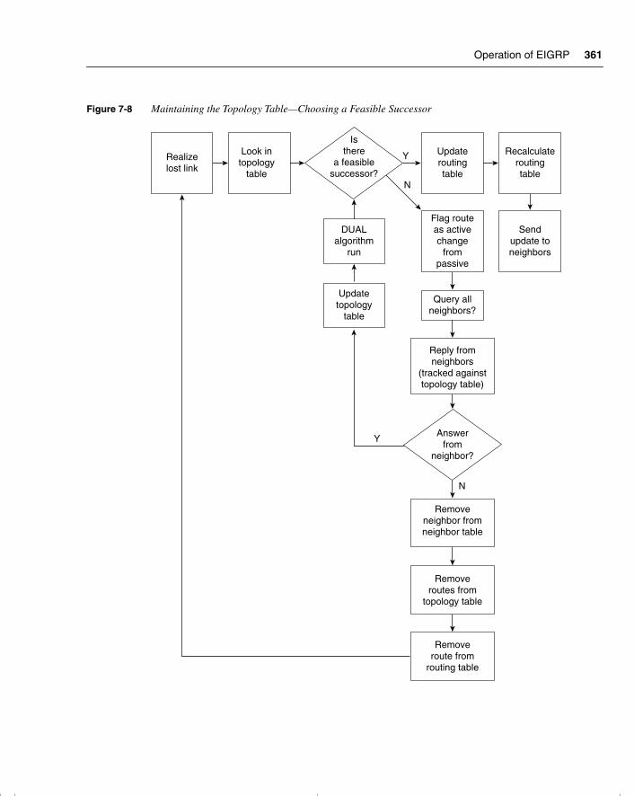
Operation of EIGRP 361
Figure 7-8 Maintaining the Topology Table—Choosing a Feasible Successor
N
N
Y
Y
Realizelost link
Look intopology
table
Isthere
a feasiblesuccessor?
Updateroutingtable
Recalculateroutingtable
DUALalgorithm
run
Flag routeas activechange
frompassive
Sendupdate toneighbors
Updatetopology
table
Query allneighbors?
Reply fromneighbors
(tracked againsttopology table)
Answerfrom
neighbor?
Removeneighbor fromneighbor table
Removeroutes from
topology table
Removeroute from
routing table
chpt_01.book Page 361 Thursday, December 21, 2000 6:22 PM
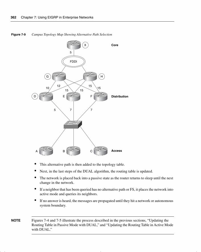
362 Chapter 7: Using EIGRP in Enterprise Networks
Figure 7-9 Campus Topology Map Showing Alternative Path Selection
• This alternative path is then added to the topology table.
• Next, in the last steps of the DUAL algorithm, the routing table is updated.
• The network is placed back into a passive state as the router returns to sleep until the next change in the network.
• If a neighbor that has been queried has no alternative path or FS, it places the network into active mode and queries its neighbors.
• If no answer is heard, the messages are propagated until they hit a network or autonomous system boundary.
NOTE Figures 7-4 and 7-5 illustrate the process described in the previous sections, “Updating the Routing Table in Passive Mode with DUAL,” and “Updating the Routing Table in Active Mode with DUAL.”
FDDI
X
5
G H
D E F
1012
15 15
1515
5 7 7
A B C
Core
Distribution
Access
chpt_01.book Page 362 Thursday, December 21, 2000 6:22 PM
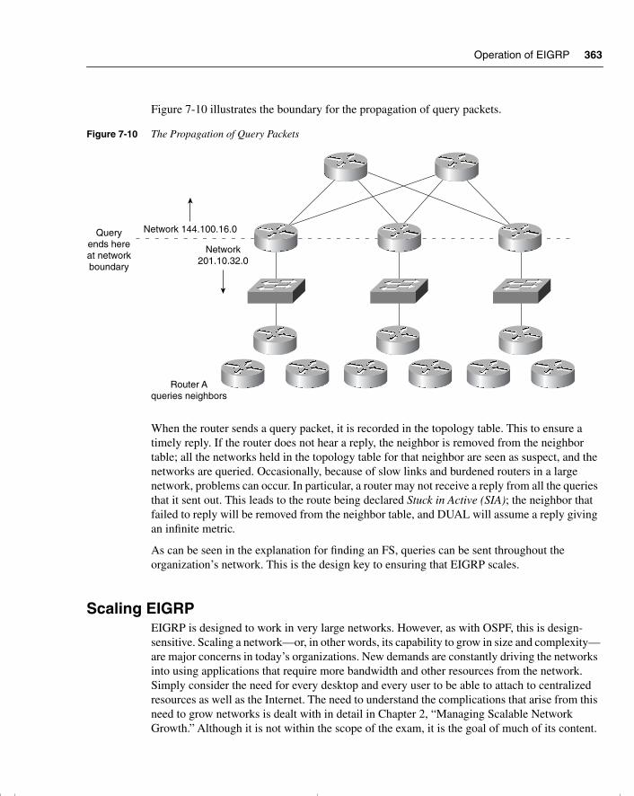
Operation of EIGRP 363
Figure 7-10 illustrates the boundary for the propagation of query packets.
Figure 7-10 The Propagation of Query Packets
When the router sends a query packet, it is recorded in the topology table. This to ensure a timely reply. If the router does not hear a reply, the neighbor is removed from the neighbor table; all the networks held in the topology table for that neighbor are seen as suspect, and the networks are queried. Occasionally, because of slow links and burdened routers in a large network, problems can occur. In particular, a router may not receive a reply from all the queries that it sent out. This leads to the route being declared Stuck in Active (SIA); the neighbor that failed to reply will be removed from the neighbor table, and DUAL will assume a reply giving an infinite metric.
As can be seen in the explanation for finding an FS, queries can be sent throughout the organization’s network. This is the design key to ensuring that EIGRP scales.
Scaling EIGRPEIGRP is designed to work in very large networks. However, as with OSPF, this is design-sensitive. Scaling a network—or, in other words, its capability to grow in size and complexity—are major concerns in today’s organizations. New demands are constantly driving the networks into using applications that require more bandwidth and other resources from the network. Simply consider the need for every desktop and every user to be able to attach to centralized resources as well as the Internet. The need to understand the complications that arise from this need to grow networks is dealt with in detail in Chapter 2, “Managing Scalable Network Growth.” Although it is not within the scope of the exam, it is the goal of much of its content.
Router Aqueries neighbors
Network 144.100.16.0
Network201.10.32.0
Queryends hereat networkboundary
chpt_01.book Page 363 Thursday, December 21, 2000 6:22 PM
364 Chapter 7: Using EIGRP in Enterprise Networks
Reasons for a Poorly Scaled EIGRP NetworkThe factors that can affect the scaling of EIGRP are these:
• The amount of information sent between neighbors
• The number of routers that are sent updates
• How far away the routers are that have to send updates
• The number of alternative paths to remote networks
Symptoms of a Poorly Scaled EIGRP Network Poorly scaled EIGRP networks can result in the following:
• A route being SIA
• Network congestion
— Delays
— Routing information being lost
— Flapping routes
— Retransmission
• Router memory running low
• Router CPU overutilized
• Unreliable circuit or unidirectional link
Some of these symptoms are caused by other factors, such as poor design, with resources overwhelmed by the tasks assigned. Often many of these symptoms will be characterized by a route being flagged as SIA, as the router waits for a reply from a neighbor across a network that cannot handle the demands made upon it.
Careful design and placement of network devices can remedy many of the problems seen in a network.
Solutions to EIGRP Scaling IssuesThe design of the network is very important to the ability to scale any network. The following solutions all revolve around a carefully thought-out network.
• Contiguous allocation of addresses, to allow summarization
• A hierarchical tiered network design, to allow summarization
• Summarization
• Sufficient network resources (both H/W and S/W) on network devices
chpt_01.book Page 364 Thursday, December 21, 2000 6:22 PM
Operation of EIGRP 365
• Sufficient bandwidth on WAN links
• Appropriate EIGRP configuration on WAN links (detailed later in this chapter)
• Filters
• Network monitoring
Design Issues Particular to EIGRPIt should be remembered that the queries must be limited to ensure that EIGRP can properly scale. If the queries are allowed to traverse the entire organization, then the problems and symptoms described will ravage your network.
Many believe that dividing the organization’s network into different EIGRP autonomous systems is a good way of limiting the query range. This is true because EIGRP does not share updates with another AS. However, many organizations that created the autonomous systems to replicate OSPF areas naturally redistribute between them so that the entire organization can share routing information. At this point, the query is propagated into the new AS, and the problem continues. Summarization is the best way to limit the query range of EIGRP networks.
If redistribution is used, then it should be accompanied by route filters to ensure that feedback loops are not generated.
Certain topologies, although valid in most instances, pose problems for the EIGRP network. This is true in particular for the hub-and-spoke design often seen implemented between the remote sites and the regional offices. The popular dual-homed configuration, while providing redundancy, also allows the potential for routers to reflect queries back to one another. Summarization and filters make this network design work well while also allowing queries to be managed effectively.
The Routing TableThe routing table is built from the topology table after DUAL has been run. The topology table is the foundation of EIGRP: This is where all the routes are stored, even after DUAL has been run. It is in the routing table that the best paths are stored and accessed by the routing process.
Now that the tables have been built, the router can make routing decisions (a process explained in the preceding chapter).
Having built the appropriate tables, the technology holds one more secret: how to maintain the tables as current and accurate.
If you understand the principles of EIGRP functionality, configuring it is straightforward. The following section deals with the commands required to configure EIGRP. Before effective configuration can be achieved, the entire network should be analyzed from a design perspective, particularly with regard to summarization. Refer to Chapter 3, “IP Addressing,” for a review of summarization.
chpt_01.book Page 365 Thursday, December 21, 2000 6:22 PM
366 Chapter 7: Using EIGRP in Enterprise Networks
Configuring EIGRPThe commands for EIGRP are consistent with the other IP routing protocols. Although IP routing is on automatically, the chosen routing protocol must be configured and the participating interfaces must be identified.
EIGRP allows for VLSM and, therefore, summarization because the mask is sent in the update packets. Although summarization is automatic, EIGRP summarizes at the NIC or major network boundary. To summarize within the NIC number, it must be manually configured. Unlike OSPF that can only summarize at the Area Border Router (ABR), EIGRP can summarize at any router.
WARNING EIGRP is a new protocol and has evolved over the past few years. It is essential that, in a practical situation, the commands and configuration be researched for the IOS code level that is installed in your network.
This section covers the following:
• Required configuration commands of EIGRP
• Optional configuration commands of EIGRP
• What each configuration command achieves
• An example of how the configuration command achieves its goal
The Required Commands for Configuring EIGRP The router needs to understand how to participate in the EIGRP network. Therefore, it requires the following:
• The EIGRP process—The routing protocol needs to be started on the router.
• The EIGRP autonomous system number—All routers sharing routing updates and participating in the larger network must be identified as part of the same autonomous system. A router will not accept an update from a router configured with a different AS number.
• Participating router interfaces—The router may not want to have all its interfaces to send or receive EIGRP routing updates. A classic example is a dialup line to a remote office. If there were only one subnet at the remote office, it would be more efficient to use default and static route commands because any updates would dial the line.
By default (unless the SETUP script is used), there is no IP routing protocol running on the Cisco router. This is not true of other protocols, however. If an IPX network address is configured on an interface, for example, the IPX RIP process will be automatically started.
chpt_01.book Page 366 Thursday, December 21, 2000 6:22 PM
Configuring EIGRP 367
To configure EIGRP as the routing protocol, the following command syntax is used:
router eigrp autonomous system number
Although EIGRP has been turned on, it has no information on how to operate. The connected networks that are to be sent in the EIGRP updates and the interfaces that participate in the EIGRP updates must be defined. If the EIGRP information is not specified, the process with insufficient configuration will never start.
WARNING Most versions of the IOS do not offer an error message, and this can make troubleshooting more difficult. Refer to the section titled “Verifying the EIGRP Operation,” later in this chapter, for more information.
The following command syntax shows the use of the network command prior to IOS 12.0(4)T:
network network number
The network command plays a similar role to that of the network command in RIP or IGRP. Unlike OSPF, in which it is possible to identify the specific address of an interface, the network command for EIGRP is stated at the class level. EIGRP does not have the design specification of areas and, therefore, has no need for granularity.
WARNING A common error is to configure the network command with an inappropriate wildcard mask when you’re confused as to which class of address is being used.
From Cisco IOS 12.0(4)T, there have been some significant changes to the network command. It is now possible to identify which interfaces are running EIGRP by stating a wildcard mask. This is similar to the use of the network command in OSPF. However, OSPF has the added parameter, which defines the area for the interface.
The new syntax is as follows:
network network-number [wildcard network-mask]no network network-number [wildcard network-mask]
The following syntax illustrates the use of the network command (the router has two Ethernet interfaces):
interface e1ip address 155.16.1.1 255.255.255.0!interface e2ip address 155.16.2.2 255.255.255.0
chpt_01.book Page 367 Thursday, December 21, 2000 6:22 PM
368 Chapter 7: Using EIGRP in Enterprise Networks
The following command indicates that EIGRP will run on interface e1 only:
router eigrp 100network 155.16.1.1 0.0.0.0
In earlier versions, as soon the first part of the command was configured, the operating system corrected the address to the NIC or major network number, 155.16.0.0, which would include both e1 and e2:
network 155.16.1.1
After the network has been defined to EIGRP, it will identify the interfaces directly connected to the routers that share that network address.
Having identified the interfaces on the router that are participating in the EIGRP domain, the following will happen:
• Updates will be received on the interface.
• Updates will be sent out the interfaces.
• The network will be advertised out all EIGRP interfaces.
• If appropriate, the Hello protocol will be propagated.
The Optional Commands for Configuring EIGRPThese commands are used to tune the way EIGRP works within your network. They should be used in reference to the design of the network and its technical requirements.
This section considers the following optional EIGRP commands:
• no auto-summary
• variance
• ip summary address
• bandwidth
• bandwidth-percent
Summarization with EIGRP This subject has been dealt with in depth in several other locations within this book. References are given to those sections in the interests of brevity. These should be referred to for revision purposes because summarization in EIGRP solves the same problems of scaling as seen in other networks.
For more information, refer to the sections, “Design Considerations in Multiple-Area OSPF,” in Chapter 6, “Using OSPF Across Multiple Areas,” and, “Summarization,” in Chapter 3.
chpt_01.book Page 368 Thursday, December 21, 2000 6:22 PM
Configuring EIGRP 369
The difference in the configuration between EIGRP and OSPF is that the OSPF is summarized only at the area boundary. Because EIGRP does not use the concept of areas, it may be configured on any router in the network. Consideration in where to summarize is determined by the hierarchical structure of the network. If summarization is not configured, EIGRP will automatically summarize at the class boundary.
There are two commands for summarization with EIGRP. The first command is no auto-summary. This command is IOS-specific, and research should be done on your IOS code level before configuring your live network.
The command applies to the entire router. This is very important because if there are slow serial interfaces or congested links, they will transmit all the subnets known on the router. This may significantly increase the overhead for the link. The solution is to configure the summary command on all interfaces, which in turn demands careful deployment of addresses.
Manual summarization is configured at the interface level, as shown here:
interface S0ip summary address eigrp autonomous-system-number address mask
Load Balancing in EIGRPEIGRP automatically load-balances across links of equal cost. Whether the traffic is sent on a per-destination or round-robin basis depends on the internal switching within the router. It is possible to configure EIGRP to load-balance across unequal paths using the variance command. This command allows the administrator to identify by the use of the multiplier parameter the metric scope for including additional paths.
The command structure is shown here:
variance multiplier
The multiplier is a number that ranges from 1 to 128. The default is 1, which allows for equal-cost load balancing. If the number is higher, it will multiply the best cost or metric value for a path by the number stated as the multiplier. All paths to the same destination that have metrics within this new range are now included in load balancing. The amount of traffic sent over each link is proportional to the metric for the path.
For example, the route to network A has four paths to it from router F and the best path gave a metric value of 10. The available routes shown in Figure 7-11 reflect these paths:
F to E to A = 30F to D to B = 15F to C to B = 15F to C to G = 10
chpt_01.book Page 369 Thursday, December 21, 2000 6:22 PM
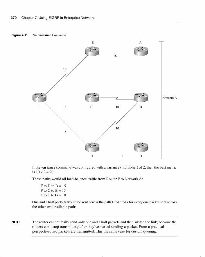
370 Chapter 7: Using EIGRP in Enterprise Networks
Figure 7-11 The variance Command
If the variance command was configured with a variance (multiplier) of 2; then the best metric is 10 × 2 = 20.
These paths would all load-balance traffic from Router F to Network A:
F to D to B = 15F to C to B = 15F to C to G = 10
One and a half packets would be sent across the path F to C to G for every one packet sent across the other two available paths.
NOTE The router cannot really send only one and a half packets and then switch the link, because the routers can’t stop transmitting after they’ve started sending a packet. From a practical perspective, two packets are transmitted. This the same case for custom queuing.
F
5
C 5 G
10
B
A
15
E
15
D5 10
Network A
chpt_01.book Page 370 Thursday, December 21, 2000 6:22 PM
Configuring EIGRP 371
NOTE Only those paths that are in the topology table as FS are eligible to be included in the variance command. Also, appreciate that the example and figure shown are highly simplified for the purpose of explanation.
Bandwidth Control A perennial concern of network administrators is the amount of bandwidth used for overhead traffic. Administrators want to minimize the amount of network control traffic sent through the network, to maximize the bandwidth available for user data. One of the major benefits of both EIGRP and OSPF is that they send as little network traffic as possible. This has the advantage of decreasing the convergence time of the network and ensuring that the network traffic that is sent arrives at the destination.
EIGRP Defaults in Bandwidth UtilizationEIGRP will not use more than 50 percent of the stated bandwidth on a link. The bandwidth command used on the interfaces of a Cisco router allows the default settings on links to be overridden. This is often necessary on serial links because the default bandwidth is 1.544 Mbps or a T1. If in reality the link is 56 kbps, it is easy to see how EIGRP could saturate the link. EIGRP will try to use 50 percent of a T1 link (772 kbps), far exceeding the real bandwidth of the line. This will mean not only the dropping of data packets due to congestion, but also the dropping of EIGRP packets. This will cause confusion in the network, not to mention miscalculated routes, retransmission, and user irritation as the network slows.
It is essential to configure all interfaces to reflect the true speed of the line.
NOTE Other technologies on a Cisco router will use this value to make decisions. Therefore, ensure that the bandwidth stated is indeed the speed of the link. When you issue the show interface command, the configured bandwidth of the link will be shown along with a field identifying the load on the line. The load is the amount of traffic sent out of the interface, proportional to the bandwidth of the link, in which the bandwidth is the stated bandwidth and not the speed of the interface.
If it is necessary to artificially lower the bandwidth command, this should be done in consideration of the other network applications.
The bandwidth is a logical construct whose value can have wide-reaching implications on the functioning of your network. It does not affect the actual speed of the link.
chpt_01.book Page 371 Thursday, December 21, 2000 6:22 PM
372 Chapter 7: Using EIGRP in Enterprise Networks
EIGRP and the Use of the bandwidth Command in WANsThe developers of EIGRP have provided configurations to suit the three different WAN environments. The three WAN environments are as follows:
• Point-to-point
• NBMA, such as Frame Relay, X25, or ATM
• Multipoint
— Point-to-point
— NBMA hybrid (this is a combination of the point-to-point and multipoint designs)
When configuring the bandwidth command, it is important to consider the actual speed of the link. It is practical to configure this only on serial lines, where the speed of the link will vary considerably. However, do not confuse the speed of the interface or access line with the bandwidth or committed information rate (CIR) of the virtual circuit (VC).
Rules in Configuring Bandwidth over an NBMA CloudCisco identifies three rules that should be followed when configuring EIGRP over an NBMA cloud:
• EIGRP traffic should not exceed the CIR capacity of the VC.
• EIGRP’s aggregated traffic over all the VCs should not exceed the access line speed of the interface.
• The bandwidth allocated to EIGRP on each VC must be the same in both directions.
If these rules are understood and followed, EIGRP works well over the WAN. If care is not taken in the configuration of the WAN, EIGRP can swamp the network.
Configuring Bandwidth over a Multipoint NetworkThe configuration of the bandwidth command in an NBMA cloud depends on the design of the VCs. If the serial line has many VCs in a multipoint configuration, then EIGRP will evenly distribute its overhead between the VCs, without the use of subinterfaces. The bandwidth command should therefore reflect the access link speed into the Frame Relay cloud. If the serial interface is accessing an NBMA environment such as Frame Relay, the situation is straightforward. Your company may have five VCs from your router’s serial interface. Each VC is 56 kbps. The access link will need a capacity of 5 × 56 kbps, or at least 2046 kbps. Remember, the aggregate configured bandwidth cannot exceed the access speed of the interface.
chpt_01.book Page 372 Thursday, December 21, 2000 6:22 PM
Configuring EIGRP 373
Configuring Bandwidth over a Hybrid Multipoint NetworkIf the multipoint network has differing speeds allocated to the VCs, a more complex solution is needed. There are two main approaches.
• To take the lowest CIR and to simply multiply this by the number of circuits. This is applied to the physical interface. The problem with this configuration is that the higher-bandwidth links will be underutilized for some things.
• If possible, it is much easier to configure and manage an environment that has used subinterfaces, where a VC is logically treated as if it were a separate interface or point-to point. The bandwidth command may be configured on each subinterface, which allows different speeds on each VC. In this second solution, subinterfaces are configured for the links with the differing CIRs. The links that have the same configured CIR are presented as a single subinterface with a bandwidth, which reflects the aggregate CIR of all the circuits.
Cisco recommends this as the preferred solution.
The following syntax shows the structure of the bandwidth command:
interface S0bandwidth speed of line
The Configuration of the Pure Point-to-Point Network If there are many VCs, there may not be enough bandwidth at the access speed of the interface to support it. The subinterfaces should be configured with a bandwidth that is much lower than the real speed of the circuit. In this case, it is necessary to use the bandwidth-percent command to indicate to the EIGRP process that it can still function.
The Use of The bandwidth-percent CommandAnother command specific to EIGRP is the bandwidth-percent command. It is easier and simpler to use the bandwidth command than the bandwidth-percent command.
The bandwidth-percent command interacts with the bandwidth command on the interface. The reason for using this command is primarily because in your network, the bandwidth command does not reflect the true speed of the link. The bandwidth command may have been altered to manipulate the routing metric and path selection of a routing protocol, such as IGRP or OSPF. It might be better to use other methods of controlling the routing metric and return the bandwidth to a true value. Otherwise, the bandwidth-percent command is available. It is possible to set a bandwidth percent that is larger than the stated bandwidth. This is in the
chpt_01.book Page 373 Thursday, December 21, 2000 6:22 PM
374 Chapter 7: Using EIGRP in Enterprise Networks
understanding that although the bandwidth may be stated to be 56 kbps, the link is in fact 256 kbps. The following shows the structure of the bandwidth-percent command:
interface S0ip bandwidth-percent eigrp autonomous-system-number percent
EIGRP can also be configured as a routing protocol for IPX and AppleTalk. The next section discusses this.
Configuring EIGRP for IPX
NOTE This section is included to place EIGRP in context. The exam will test only on topics pertaining to EIGRP using IP. Therefore, this section should be read only for interest and should not be studied in depth in preparation for the Routing exam.
The configuration of IPX is very similar to IP. The difference is that IPX is a client/server-based protocol that was originally designed to operate in a LAN environment. Although Novell has improved its technology over the past few years to allow the networks to scale across the enterprise domain, IPX can still prove both a design and an implementation headache for the administrator. Typically, the amount of overhead generated in a client/server network is greater than that of a peer-to-peer network. This overhead becomes problematic when slower WAN links are used and bandwidth is at a premium. In this environment, EIGRP is a powerful tool.
EIGRP offers the following main features to an IPX enterprise network:
• Incremental updates for both RIP and SAP traffic
• Faster convergence of the network
• An increased diameter of the network, through the use of the metric and hop count
• A more complex and sophisticated routing metric
• Automatic redistribution of networks among IPX RIP, NLSP, and EIGRP
The operation of EIGRP for IPX is the same as that of IP, although the EIGRP metric uses both bandwidth and delay in calculating the best path.
EIGRP for IPX uses the same major components:
• Reliable transport mechanism for updates
• DUAL
• Neighbor discovery/recovery
• Protocol-dependent modules
chpt_01.book Page 374 Thursday, December 21, 2000 6:22 PM
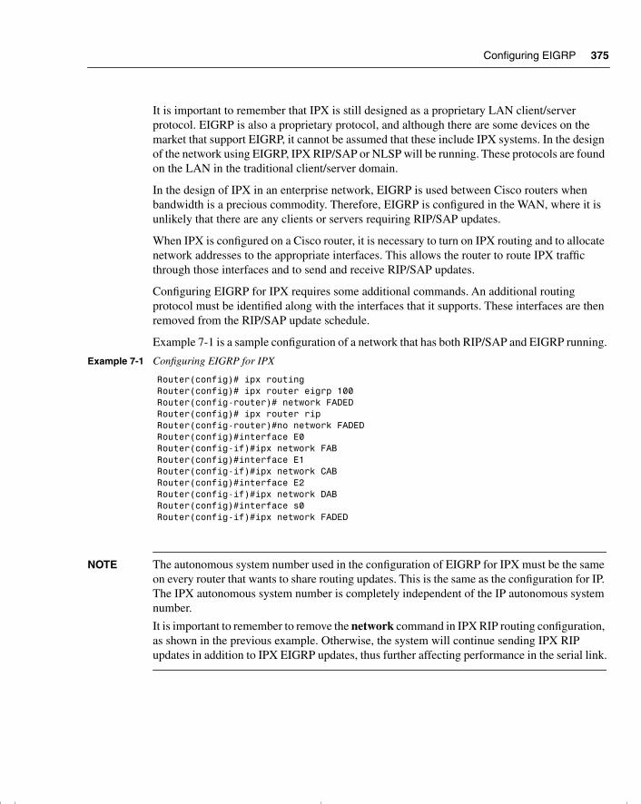
Configuring EIGRP 375
It is important to remember that IPX is still designed as a proprietary LAN client/server protocol. EIGRP is also a proprietary protocol, and although there are some devices on the market that support EIGRP, it cannot be assumed that these include IPX systems. In the design of the network using EIGRP, IPX RIP/SAP or NLSP will be running. These protocols are found on the LAN in the traditional client/server domain.
In the design of IPX in an enterprise network, EIGRP is used between Cisco routers when bandwidth is a precious commodity. Therefore, EIGRP is configured in the WAN, where it is unlikely that there are any clients or servers requiring RIP/SAP updates.
When IPX is configured on a Cisco router, it is necessary to turn on IPX routing and to allocate network addresses to the appropriate interfaces. This allows the router to route IPX traffic through those interfaces and to send and receive RIP/SAP updates.
Configuring EIGRP for IPX requires some additional commands. An additional routing protocol must be identified along with the interfaces that it supports. These interfaces are then removed from the RIP/SAP update schedule.
Example 7-1 is a sample configuration of a network that has both RIP/SAP and EIGRP running.
NOTE The autonomous system number used in the configuration of EIGRP for IPX must be the same on every router that wants to share routing updates. This is the same as the configuration for IP. The IPX autonomous system number is completely independent of the IP autonomous system number.
It is important to remember to remove the network command in IPX RIP routing configuration, as shown in the previous example. Otherwise, the system will continue sending IPX RIP updates in addition to IPX EIGRP updates, thus further affecting performance in the serial link.
Example 7-1 Configuring EIGRP for IPX
Router(config)# ipx routingRouter(config)# ipx router eigrp 100Router(config-router)# network FADEDRouter(config)# ipx router ripRouter(config-router)#no network FADEDRouter(config)#interface E0Router(config-if)#ipx network FABRouter(config)#interface E1Router(config-if)#ipx network CABRouter(config)#interface E2Router(config-if)#ipx network DABRouter(config)#interface s0Router(config-if)#ipx network FADED
chpt_01.book Page 375 Thursday, December 21, 2000 6:22 PM
376 Chapter 7: Using EIGRP in Enterprise Networks
EIGRP will automatically redistribute its routing information into RIP/SAP. It will also send only incremental updates through serial interfaces and will send periodic updates through LAN interfaces. EIGRP can be manually configured to send incremental updates out of the LAN interface, if required. Incremental updates might apply to networks that form a backbone in the network design—for example, where an FDDI ring or Fast Ethernet segments are connecting the distribution layer and forming the campus backbone.
The following is the command syntax to force a LAN interface to send incremental updates:
interface f0ipx sap-incremental eigrp autonomous-system-number
Configuring EIGRP for AppleTalk
NOTE This section is included to place EIGRP in context. The exam will test only on topics pertaining to EIGRP using IP. Therefore, this section should be read only for interest and should not be studied in depth in preparation for the Routing exam.
EIGRP also supports the client/server protocol AppleTalk. Conceptually, the use of EIGRP is the same, although the configuration details differ. The main difference in configuration is that, whereas in configuring IP or IPX the autonomous system number must be the same for all routers sharing routing information, with AppleTalk, every router must have a unique process ID.
The configuration details of EIGRP for AppleTalk are beyond the scope of this book. Refer to the Cisco web site and documentation for details and design and configuration guidelines.
Moving Toward IP
In reality, most organizations are porting all their client/server platforms into IP, with the sup-port of the vendors of the client/server products. EIGRP for either IPX or AppleTalk is most powerful when transitioning your organization to IP. If you are using EIGRP, be aware of the fast development of the technology, and ensure compatibility between the IOS versions by researching the Cisco web site.
Verifying the EIGRP OperationThe set of commands in this section is invaluable. These commands are crucial in the configuration, maintenance, and troubleshooting of a live network. As such, they are a necessary set of tools for use on a daily basis as well as on the CCIE lab exam.
chpt_01.book Page 376 Thursday, December 21, 2000 6:22 PM
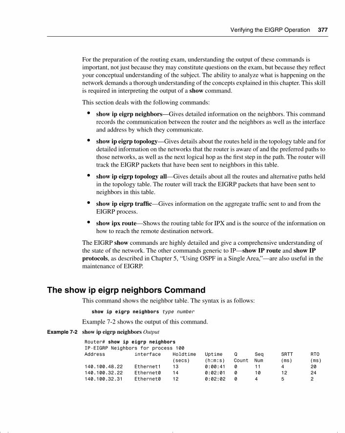
Verifying the EIGRP Operation 377
For the preparation of the routing exam, understanding the output of these commands is important, not just because they may constitute questions on the exam, but because they reflect your conceptual understanding of the subject. The ability to analyze what is happening on the network demands a thorough understanding of the concepts explained in this chapter. This skill is required in interpreting the output of a show command.
This section deals with the following commands:
• show ip eigrp neighbors—Gives detailed information on the neighbors. This command records the communication between the router and the neighbors as well as the interface and address by which they communicate.
• show ip eigrp topology—Gives details about the routes held in the topology table and for detailed information on the networks that the router is aware of and the preferred paths to those networks, as well as the next logical hop as the first step in the path. The router will track the EIGRP packets that have been sent to neighbors in this table.
• show ip eigrp topology all—Gives details about all the routes and alternative paths held in the topology table. The router will track the EIGRP packets that have been sent to neighbors in this table.
• show ip eigrp traffic—Gives information on the aggregate traffic sent to and from the EIGRP process.
• show ipx route—Shows the routing table for IPX and is the source of the information on how to reach the remote destination network.
The EIGRP show commands are highly detailed and give a comprehensive understanding of the state of the network. The other commands generic to IP—show IP route and show IP protocols, as described in Chapter 5, “Using OSPF in a Single Area,”—are also useful in the maintenance of EIGRP.
The show ip eigrp neighbors CommandThis command shows the neighbor table. The syntax is as follows:
show ip eigrp neighbors type number
Example 7-2 shows the output of this command.
Example 7-2 show ip eigrp neighbors Output
Router# show ip eigrp neighborsIP-EIGRP Neighbors for process 100Address interface Holdtime Uptime Q Seq SRTT RTO (secs) (h:m:s) Count Num (ms) (ms)140.100.48.22 Ethernet1 13 0:00:41 0 11 4 20140.100.32.22 Ethernet0 14 0:02:01 0 10 12 24140.100.32.31 Ethernet0 12 0:02:02 0 4 5 2
chpt_01.book Page 377 Thursday, December 21, 2000 6:22 PM
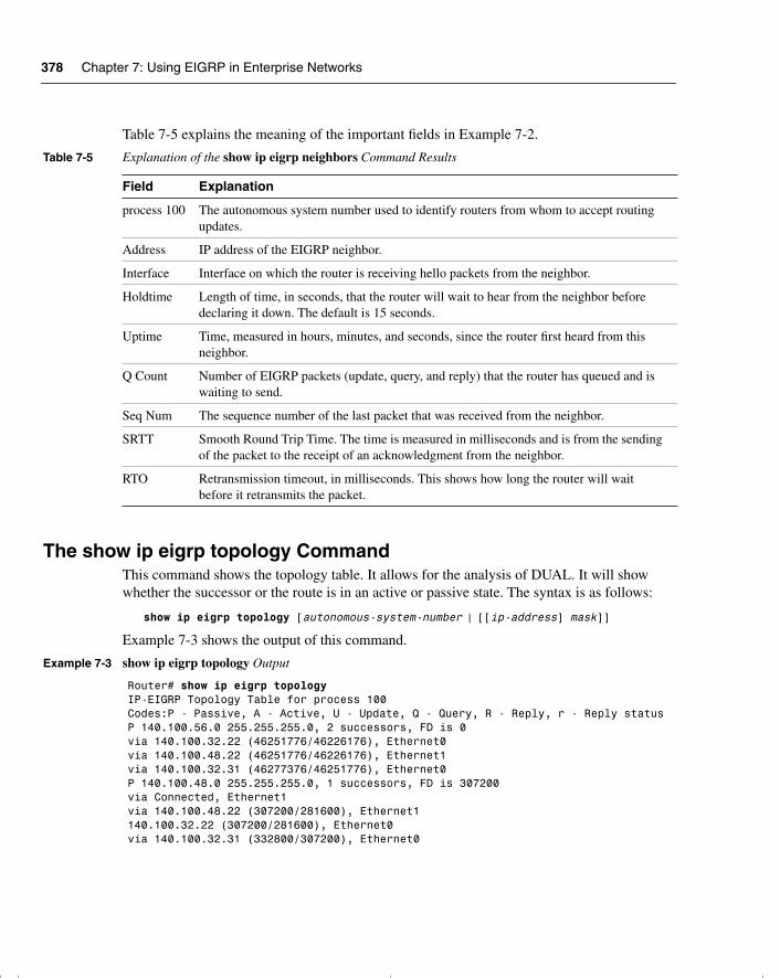
378 Chapter 7: Using EIGRP in Enterprise Networks
Table 7-5 explains the meaning of the important fields in Example 7-2.
The show ip eigrp topology CommandThis command shows the topology table. It allows for the analysis of DUAL. It will show whether the successor or the route is in an active or passive state. The syntax is as follows:
show ip eigrp topology [autonomous-system-number | [[ip-address] mask]]
Example 7-3 shows the output of this command.
Table 7-5 Explanation of the show ip eigrp neighbors Command Results
Field Explanation
process 100 The autonomous system number used to identify routers from whom to accept routing updates.
Address IP address of the EIGRP neighbor.
Interface Interface on which the router is receiving hello packets from the neighbor.
Holdtime Length of time, in seconds, that the router will wait to hear from the neighbor before declaring it down. The default is 15 seconds.
Uptime Time, measured in hours, minutes, and seconds, since the router first heard from this neighbor.
Q Count Number of EIGRP packets (update, query, and reply) that the router has queued and is waiting to send.
Seq Num The sequence number of the last packet that was received from the neighbor.
SRTT Smooth Round Trip Time. The time is measured in milliseconds and is from the sending of the packet to the receipt of an acknowledgment from the neighbor.
RTO Retransmission timeout, in milliseconds. This shows how long the router will wait before it retransmits the packet.
Example 7-3 show ip eigrp topology Output
Router# show ip eigrp topologyIP-EIGRP Topology Table for process 100Codes:P - Passive, A - Active, U - Update, Q - Query, R - Reply, r - Reply statusP 140.100.56.0 255.255.255.0, 2 successors, FD is 0via 140.100.32.22 (46251776/46226176), Ethernet0via 140.100.48.22 (46251776/46226176), Ethernet1via 140.100.32.31 (46277376/46251776), Ethernet0P 140.100.48.0 255.255.255.0, 1 successors, FD is 307200via Connected, Ethernet1via 140.100.48.22 (307200/281600), Ethernet1140.100.32.22 (307200/281600), Ethernet0via 140.100.32.31 (332800/307200), Ethernet0
chpt_01.book Page 378 Thursday, December 21, 2000 6:22 PM
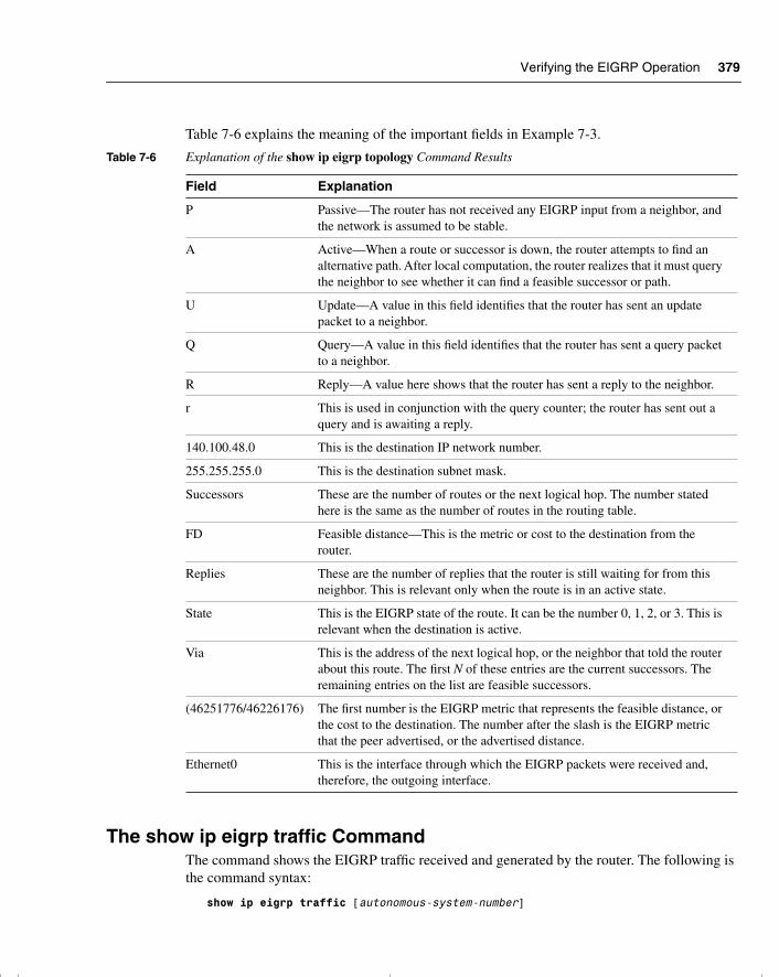
Verifying the EIGRP Operation 379
Table 7-6 explains the meaning of the important fields in Example 7-3.
The show ip eigrp traffic CommandThe command shows the EIGRP traffic received and generated by the router. The following is the command syntax:
show ip eigrp traffic [autonomous-system-number]
Table 7-6 Explanation of the show ip eigrp topology Command Results
Field Explanation
P Passive—The router has not received any EIGRP input from a neighbor, and the network is assumed to be stable.
A Active—When a route or successor is down, the router attempts to find an alternative path. After local computation, the router realizes that it must query the neighbor to see whether it can find a feasible successor or path.
U Update—A value in this field identifies that the router has sent an update packet to a neighbor.
Q Query—A value in this field identifies that the router has sent a query packet to a neighbor.
R Reply—A value here shows that the router has sent a reply to the neighbor.
r This is used in conjunction with the query counter; the router has sent out a query and is awaiting a reply.
140.100.48.0 This is the destination IP network number.
255.255.255.0 This is the destination subnet mask.
Successors These are the number of routes or the next logical hop. The number stated here is the same as the number of routes in the routing table.
FD Feasible distance—This is the metric or cost to the destination from the router.
Replies These are the number of replies that the router is still waiting for from this neighbor. This is relevant only when the route is in an active state.
State This is the EIGRP state of the route. It can be the number 0, 1, 2, or 3. This is relevant when the destination is active.
Via This is the address of the next logical hop, or the neighbor that told the router about this route. The first N of these entries are the current successors. The remaining entries on the list are feasible successors.
(46251776/46226176) The first number is the EIGRP metric that represents the feasible distance, or the cost to the destination. The number after the slash is the EIGRP metric that the peer advertised, or the advertised distance.
Ethernet0 This is the interface through which the EIGRP packets were received and, therefore, the outgoing interface.
chpt_01.book Page 379 Thursday, December 21, 2000 6:22 PM
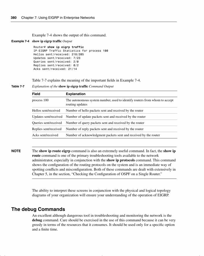
380 Chapter 7: Using EIGRP in Enterprise Networks
Example 7-4 shows the output of this command.
Table 7-7 explains the meaning of the important fields in Example 7-4.
NOTE The show ip route eigrp command is also an extremely useful command. In fact, the show ip route command is one of the primary troubleshooting tools available to the network administrator, especially in conjunction with the show ip protocols command. This command shows the configuration of the routing protocols on the system and is an immediate way of spotting conflicts and misconfiguration. Both of these commands are dealt with extensively in Chapter 5, in the section, “Checking the Configuration of OSPF on a Single Router.”
The ability to interpret these screens in conjunction with the physical and logical topology diagrams of your organization will ensure your understanding of the operation of EIGRP.
The debug CommandsAn excellent although dangerous tool in troubleshooting and monitoring the network is the debug command. Care should be exercised in the use of this command because it can be very greedy in terms of the resources that it consumes. It should be used only for a specific option and a finite time.
Example 7-4 show ip eigrp traffic Output
Router# show ip eigrp trafficIP-EIGRP Traffic Statistics for process 100Hellos sent/received: 218/205Updates sent/received: 7/23Queries sent/received: 2/0Replies sent/received: 0/2Acks sent/received: 21/14
Table 7-7 Explanation of the show ip eigrp traffic Command Output
Field Explanation
process 100 The autonomous system number, used to identify routers from whom to accept routing updates
Hellos sent/received Number of hello packets sent and received by the router
Updates sent/received Number of update packets sent and received by the router
Queries sent/received Number of query packets sent and received by the router
Replies sent/received Number of reply packets sent and received by the router
Acks sent/received Number of acknowledgment packets sent and received by the router
chpt_01.book Page 380 Thursday, December 21, 2000 6:22 PM
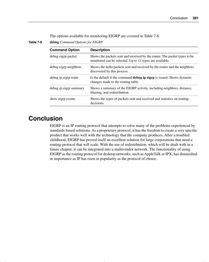
Conclusion 381
The options available for monitoring EIGRP are covered in Table 7-8.
ConclusionEIGRP is an IP routing protocol that attempts to solve many of the problems experienced by standards-based solutions. As a proprietary protocol, it has the freedom to create a very specific product that works well with the technology that the company produces. After a troubled childhood, EIGRP has proved itself an excellent solution for large corporations that need a routing protocol that will scale. With the use of redistribution, which will be dealt with in a future chapter, it can be integrated into a multivendor network. The functionality of using EIGRP as the routing protocol for desktop networks, such as AppleTalk or IPX, has diminished in importance as IP has risen in popularity as the protocol of choice.
Table 7-8 debug Command Options for EIGRP
Command Option Description
debug eigrp packet Shows the packets sent and received by the router. The packet types to be monitored can be selected. Up to 11 types are available.
debug eigrp neighbors Shows the hello packets sent and received by the router and the neighbors discovered by this process.
debug ip eigrp route Is the default if the command debug ip eigrp is issued. Shows dynamic changes made to the routing table.
debug ip eigrp summary Shows a summary of the EIGRP activity, including neighbors, distance, filtering, and redistribution.
show eigrp events Shows the types of packets sent and received and statistics on routing decisions.
chpt_01.book Page 381 Thursday, December 21, 2000 6:22 PM
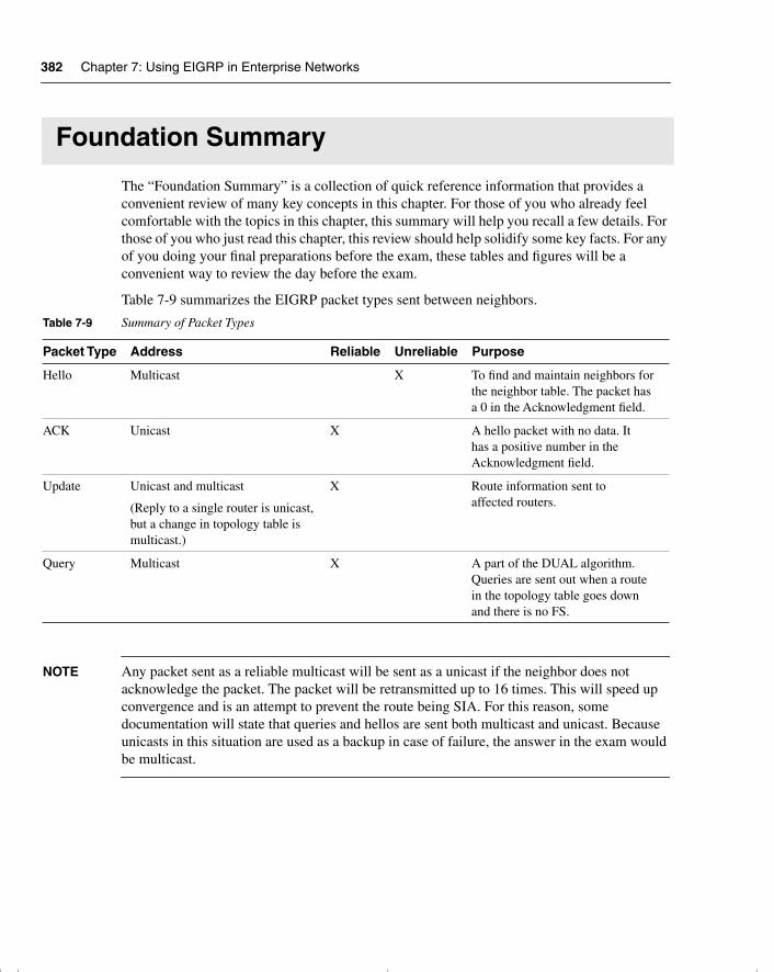
382 Chapter 7: Using EIGRP in Enterprise Networks
Foundation Summary
The “Foundation Summary” is a collection of quick reference information that provides a convenient review of many key concepts in this chapter. For those of you who already feel comfortable with the topics in this chapter, this summary will help you recall a few details. For those of you who just read this chapter, this review should help solidify some key facts. For any of you doing your final preparations before the exam, these tables and figures will be a convenient way to review the day before the exam.
Table 7-9 summarizes the EIGRP packet types sent between neighbors.
NOTE Any packet sent as a reliable multicast will be sent as a unicast if the neighbor does not acknowledge the packet. The packet will be retransmitted up to 16 times. This will speed up convergence and is an attempt to prevent the route being SIA. For this reason, some documentation will state that queries and hellos are sent both multicast and unicast. Because unicasts in this situation are used as a backup in case of failure, the answer in the exam would be multicast.
Table 7-9 Summary of Packet Types
Packet Type Address Reliable Unreliable Purpose
Hello Multicast X To find and maintain neighbors for the neighbor table. The packet has a 0 in the Acknowledgment field.
ACK Unicast X A hello packet with no data. It has a positive number in theAcknowledgment field.
Update Unicast and multicast
(Reply to a single router is unicast, but a change in topology table is multicast.)
X Route information sent to affected routers.
Query Multicast X A part of the DUAL algorithm. Queries are sent out when a route in the topology table goes down and there is no FS.
chpt_01.book Page 382 Thursday, December 21, 2000 6:22 PM
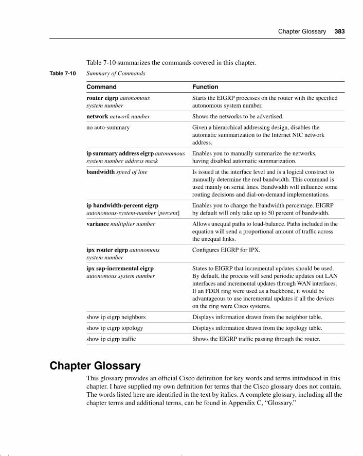
Chapter Glossary 383
Table 7-10 summarizes the commands covered in this chapter.
Chapter GlossaryThis glossary provides an official Cisco definition for key words and terms introduced in this chapter. I have supplied my own definition for terms that the Cisco glossary does not contain. The words listed here are identified in the text by italics. A complete glossary, including all the chapter terms and additional terms, can be found in Appendix C, “Glossary.”
Table 7-10 Summary of Commands
Command Function
router eigrp autonomous system number
Starts the EIGRP processes on the router with the specified autonomous system number.
network network number Shows the networks to be advertised.
no auto-summary Given a hierarchical addressing design, disables the automatic summarization to the Internet NIC network address.
ip summary address eigrp autonomous system number address mask
Enables you to manually summarize the networks, having disabled automatic summarization.
bandwidth speed of line Is issued at the interface level and is a logical construct to manually determine the real bandwidth. This command is used mainly on serial lines. Bandwidth will influence some routing decisions and dial-on-demand implementations.
ip bandwidth-percent eigrp autonomous-system-number [percent]
Enables you to change the bandwidth percentage. EIGRP by default will only take up to 50 percent of bandwidth.
variance multiplier number Allows unequal paths to load-balance. Paths included in the equation will send a proportional amount of traffic across the unequal links.
ipx router eigrp autonomous system number
Configures EIGRP for IPX.
ipx sap-incremental eigrp autonomous system number
States to EIGRP that incremental updates should be used. By default, the process will send periodic updates out LAN interfaces and incremental updates through WAN interfaces. If an FDDI ring were used as a backbone, it would be advantageous to use incremental updates if all the devices on the ring were Cisco systems.
show ip eigrp neighbors Displays information drawn from the neighbor table.
show ip eigrp topology Displays information drawn from the topology table.
show ip eigrp traffic Shows the EIGRP traffic passing through the router.
chpt_01.book Page 383 Thursday, December 21, 2000 6:22 PM
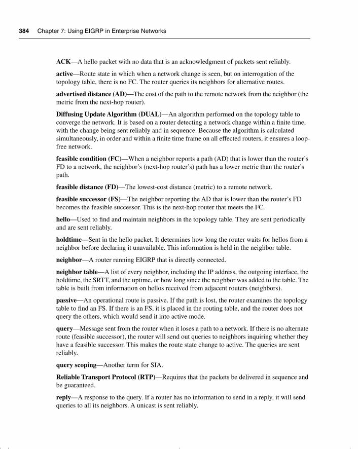
384 Chapter 7: Using EIGRP in Enterprise Networks
ACK—A hello packet with no data that is an acknowledgment of packets sent reliably.
active—Route state in which when a network change is seen, but on interrogation of the topology table, there is no FC. The router queries its neighbors for alternative routes.
advertised distance (AD)—The cost of the path to the remote network from the neighbor (the metric from the next-hop router).
Diffusing Update Algorithm (DUAL)—An algorithm performed on the topology table to converge the network. It is based on a router detecting a network change within a finite time, with the change being sent reliably and in sequence. Because the algorithm is calculated simultaneously, in order and within a finite time frame on all effected routers, it ensures a loop-free network.
feasible condition (FC)—When a neighbor reports a path (AD) that is lower than the router’s FD to a network, the neighbor’s (next-hop router’s) path has a lower metric than the router’s path.
feasible distance (FD)—The lowest-cost distance (metric) to a remote network.
feasible successor (FS)—The neighbor reporting the AD that is lower than the router’s FD becomes the feasible successor. This is the next-hop router that meets the FC.
hello—Used to find and maintain neighbors in the topology table. They are sent periodically and are sent reliably.
holdtime—Sent in the hello packet. It determines how long the router waits for hellos from a neighbor before declaring it unavailable. This information is held in the neighbor table.
neighbor—A router running EIGRP that is directly connected.
neighbor table—A list of every neighbor, including the IP address, the outgoing interface, the holdtime, the SRTT, and the uptime, or how long since the neighbor was added to the table. The table is built from information on hellos received from adjacent routers (neighbors).
passive—An operational route is passive. If the path is lost, the router examines the topology table to find an FS. If there is an FS, it is placed in the routing table, and the router does not query the others, which would send it into active mode.
query—Message sent from the router when it loses a path to a network. If there is no alternate route (feasible successor), the router will send out queries to neighbors inquiring whether they have a feasible successor. This makes the route state change to active. The queries are sent reliably.
query scoping—Another term for SIA.
Reliable Transport Protocol (RTP)—Requires that the packets be delivered in sequence and be guaranteed.
reply—A response to the query. If a router has no information to send in a reply, it will send queries to all its neighbors. A unicast is sent reliably.
chpt_01.book Page 384 Thursday, December 21, 2000 6:22 PM
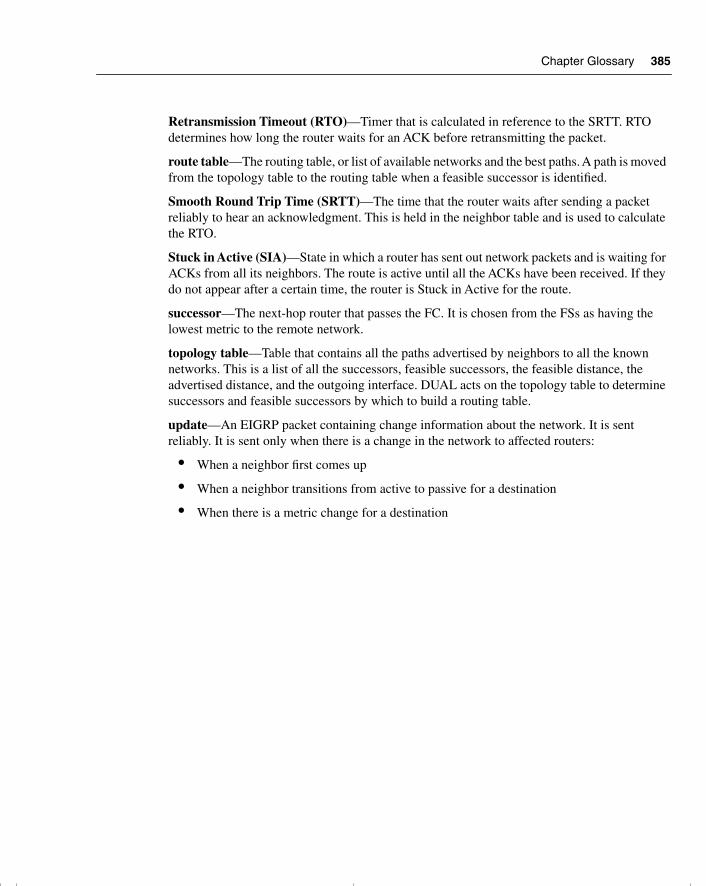
Chapter Glossary 385
Retransmission Timeout (RTO)—Timer that is calculated in reference to the SRTT. RTO determines how long the router waits for an ACK before retransmitting the packet.
route table—The routing table, or list of available networks and the best paths. A path is moved from the topology table to the routing table when a feasible successor is identified.
Smooth Round Trip Time (SRTT)—The time that the router waits after sending a packet reliably to hear an acknowledgment. This is held in the neighbor table and is used to calculate the RTO.
Stuck in Active (SIA)—State in which a router has sent out network packets and is waiting for ACKs from all its neighbors. The route is active until all the ACKs have been received. If they do not appear after a certain time, the router is Stuck in Active for the route.
successor—The next-hop router that passes the FC. It is chosen from the FSs as having the lowest metric to the remote network.
topology table—Table that contains all the paths advertised by neighbors to all the known networks. This is a list of all the successors, feasible successors, the feasible distance, the advertised distance, and the outgoing interface. DUAL acts on the topology table to determine successors and feasible successors by which to build a routing table.
update—An EIGRP packet containing change information about the network. It is sent reliably. It is sent only when there is a change in the network to affected routers:
• When a neighbor first comes up
• When a neighbor transitions from active to passive for a destination
• When there is a metric change for a destination
chpt_01.book Page 385 Thursday, December 21, 2000 6:22 PM
386 Chapter 7: Using EIGRP in Enterprise Networks
Q&A
The following questions test your understanding of the topics covered in this chapter. The final questions in this section repeat of the opening “Do I Know This Already?” questions. These are repeated to enable you to test your progress. After you have answered the questions, find the answers in Appendix A. If you get an answer wrong, review the answer and ensure that you understand the reason for your mistake. If you are confused by the answer, refer to the appropriate text in the chapter to review the concepts.
1 If a router does not have a feasible successor, what action will it take?
______________________________________________________________________
______________________________________________________________________
______________________________________________________________________
2 When does EIGRP need to be manually redistributed into another EIGRP process?
______________________________________________________________________
______________________________________________________________________
______________________________________________________________________
3 Which timers are tracked in the neighbor table?
______________________________________________________________________
______________________________________________________________________
______________________________________________________________________
4 What is the difference between an update and a query?
______________________________________________________________________
______________________________________________________________________
______________________________________________________________________
5 When does EIGRP recalculate the topology table?
______________________________________________________________________
______________________________________________________________________
______________________________________________________________________
chpt_01.book Page 386 Thursday, December 21, 2000 6:22 PM
Q&A 387
6 EIGRP has a default limit set on the amount of bandwidth that it can use for EIGRP packets. What is the default percentage limit?
_______________________________________________________________________
_______________________________________________________________________
_______________________________________________________________________
7 State two rules for designing a scalable EIGRP network.
_______________________________________________________________________
_______________________________________________________________________
_______________________________________________________________________
8 What is the preferred configuration for a hybrid multipoint NBMA network when one VC has a CIR of 56 kbps and the other five VCs each have a CIR of 256 kbps?
_______________________________________________________________________
_______________________________________________________________________
_______________________________________________________________________
9 With four Frame Relay circuits in a multipoint solution and a bandwidth configuration of 224, what is the allocation per circuit, and where would the bandwidth command be configured?
_______________________________________________________________________
_______________________________________________________________________
_______________________________________________________________________
10 Explain the purpose of the command no auto-summary.
_______________________________________________________________________
_______________________________________________________________________
_______________________________________________________________________
11 Explain the meaning of the command ip bandwidth-percent eigrp 63 100.
_______________________________________________________________________
_______________________________________________________________________
_______________________________________________________________________
chpt_01.book Page 387 Thursday, December 21, 2000 6:22 PM
388 Chapter 7: Using EIGRP in Enterprise Networks
12 EIGRP may be used to send information about which three routing protocols?
______________________________________________________________________
______________________________________________________________________
______________________________________________________________________
13 Which EIGRP packets are sent reliably?
______________________________________________________________________
______________________________________________________________________
______________________________________________________________________
14 In what instances will EIGRP automatically redistribute?
______________________________________________________________________
______________________________________________________________________
______________________________________________________________________
15 How long is the holdtime, by default?
______________________________________________________________________
______________________________________________________________________
______________________________________________________________________
16 What is an EIGRP topology table, and what does it contain?
______________________________________________________________________
______________________________________________________________________
______________________________________________________________________
17 What is the advertised distance in EIGRP, and how is it distinguished from the feasible distance?
______________________________________________________________________
______________________________________________________________________
______________________________________________________________________
18 What EIGRP algorithm is run to create entries for the routing table?
______________________________________________________________________
______________________________________________________________________
______________________________________________________________________
chpt_01.book Page 388 Thursday, December 21, 2000 6:22 PM
Q&A 389
19 When does EIGRP place a network in active mode?
_______________________________________________________________________
_______________________________________________________________________
_______________________________________________________________________
20 By default, EIGRP summarizes at which boundary?
_______________________________________________________________________
_______________________________________________________________________
_______________________________________________________________________
21 What is Stuck in Active?
_______________________________________________________________________
_______________________________________________________________________
_______________________________________________________________________
22 What is the variance command used for?
_______________________________________________________________________
_______________________________________________________________________
_______________________________________________________________________
23 State two factors that influence EIGRP scalability.
_______________________________________________________________________
_______________________________________________________________________
_______________________________________________________________________
24 What command is used to display which routes are in passive or active mode?
_______________________________________________________________________
_______________________________________________________________________
_______________________________________________________________________
25 What command is used in EIGRP to perform manual summarization?
_______________________________________________________________________
_______________________________________________________________________
_______________________________________________________________________
chpt_01.book Page 389 Thursday, December 21, 2000 6:22 PM
390 Chapter 7: Using EIGRP in Enterprise Networks
26 For Frame Relay, when would you configure the physical interface (as opposed to a subinterface) with the bandwidth command?
______________________________________________________________________
______________________________________________________________________
______________________________________________________________________
27 Which command is used to display all types of EIGRP packets that are both received and sent by a router?
______________________________________________________________________
______________________________________________________________________
______________________________________________________________________
chpt_01.book Page 390 Thursday, December 21, 2000 6:22 PM
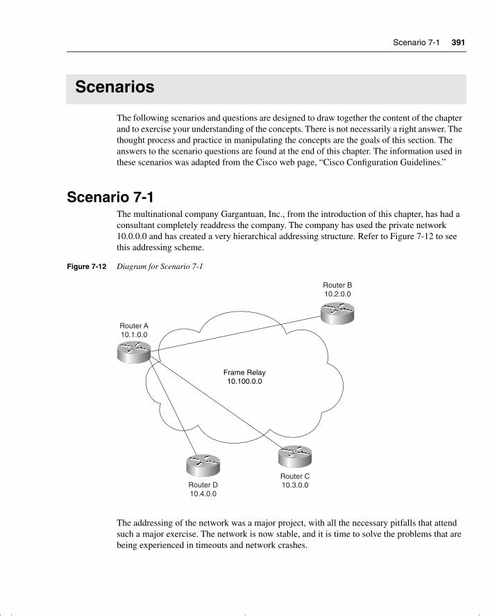
Scenario 7-1 391
Scenarios
The following scenarios and questions are designed to draw together the content of the chapter and to exercise your understanding of the concepts. There is not necessarily a right answer. The thought process and practice in manipulating the concepts are the goals of this section. The answers to the scenario questions are found at the end of this chapter. The information used in these scenarios was adapted from the Cisco web page, “Cisco Configuration Guidelines.”
Scenario 7-1The multinational company Gargantuan, Inc., from the introduction of this chapter, has had a consultant completely readdress the company. The company has used the private network 10.0.0.0 and has created a very hierarchical addressing structure. Refer to Figure 7-12 to see this addressing scheme.
Figure 7-12 Diagram for Scenario 7-1
The addressing of the network was a major project, with all the necessary pitfalls that attend such a major exercise. The network is now stable, and it is time to solve the problems that are being experienced in timeouts and network crashes.
Frame Relay10.100.0.0
Router A10.1.0.0
Router D10.4.0.0
Router C10.3.0.0
Router B10.2.0.0
chpt_01.book Page 391 Thursday, December 21, 2000 6:22 PM
392 Chapter 7: Using EIGRP in Enterprise Networks
The consultant assured the company that the resolution to the delays was the addressing scheme, but although the network is easier to manage, there has been no change in the congestion on the network. In addition, EIGRP appears to be losing routes from its routing tables, which is adding to the problem.
The consultant was correct: The network needed to be readdressed to allow EIGRP to function effectively. Unfortunately, the company did not read the report carefully and missed the other part of the solution.
1 What needs to be done in addition to solve the problems caused by EIGRP? Give the configuration commands necessary to activate this solution on Router A.
The WAN is a Frame Relay cloud, and Router A is the hub in the hub-and-spoke configuration. Each VC is 56 kbps.
2 Give the commands to configure Router A for EIGRP over this NBMA cloud.
3 Give the commands to configure Router B for EIGRP over this NBMA cloud.
Scenario 7-2Given the configuration of EIGRP in Example 7-5, perform the tasks and answer the questions listed. The WAN has light user traffic and is a hub-and-spoke configuration, as shown in Figure 7-13.
The 256 kbps access line to the hub has 56 kbps access lines to each of 10 spoke sites. Each link has a Frame Relay CIR of 56 kbps. The access line to each router reflects the CIR. The access line to the hub router, Router A, is 256 kbps, but the CIR of the hub is the same as its access line.
From a Frame Relay perspective, it is said that a circuit is oversubscribed when the sum of CIRs of the remote circuits is higher than the CIR of the hub location. With 10 links, each with a CIR of 56 kbps, this circuit is clearly oversubscribed.
Example 7-5 Scenario 7-2 Configuration
interface Serial 0 encapsulation frame-relay
interface Serial 0.1 point-to-point bandwidth 25 ip bandwidth-percent eigrp 123 90
interface Serial 0.2 point-to-point bandwidth 25 ip bandwidth-percent eigrp 123 90
...
chpt_01.book Page 392 Thursday, December 21, 2000 6:22 PM
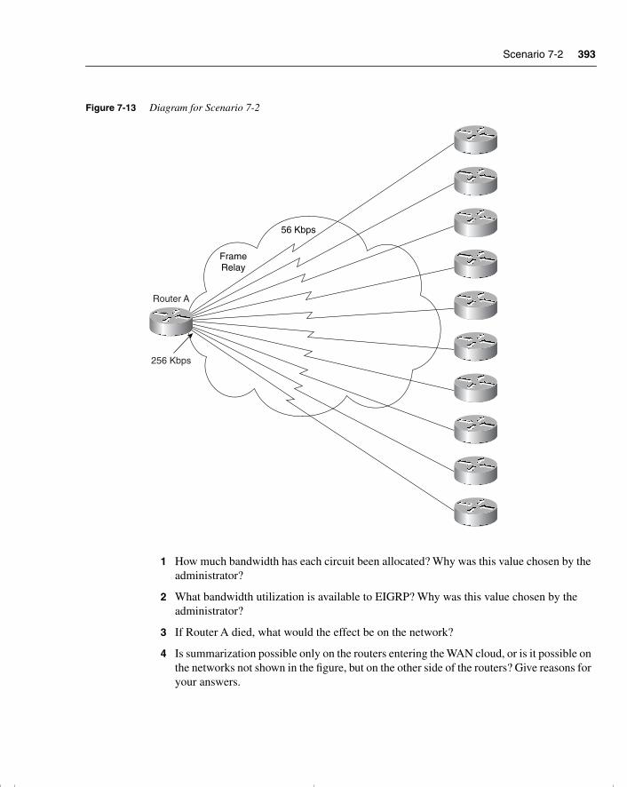
Scenario 7-2 393
Figure 7-13 Diagram for Scenario 7-2
1 How much bandwidth has each circuit been allocated? Why was this value chosen by the administrator?
2 What bandwidth utilization is available to EIGRP? Why was this value chosen by the administrator?
3 If Router A died, what would the effect be on the network?
4 Is summarization possible only on the routers entering the WAN cloud, or is it possible on the networks not shown in the figure, but on the other side of the routers? Give reasons for your answers.
FrameRelay
Router A
256 Kbps
56 Kbps
chpt_01.book Page 393 Thursday, December 21, 2000 6:22 PM
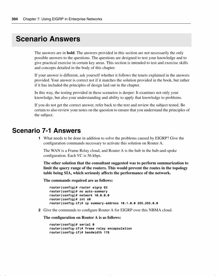
394 Chapter 7: Using EIGRP in Enterprise Networks
Scenario Answers
The answers are in bold. The answers provided in this section are not necessarily the only possible answers to the questions. The questions are designed to test your knowledge and to give practical exercise in certain key areas. This section is intended to test and exercise skills and concepts detailed in the body of this chapter.
If your answer is different, ask yourself whether it follows the tenets explained in the answers provided. Your answer is correct not if it matches the solution provided in the book, but rather if it has included the principles of design laid out in the chapter.
In this way, the testing provided in these scenarios is deeper: It examines not only your knowledge, but also your understanding and ability to apply that knowledge to problems.
If you do not get the correct answer, refer back to the text and review the subject tested. Be certain to also review your notes on the question to ensure that you understand the principles of the subject.
Scenario 7-1 Answers1 What needs to be done in addition to solve the problems caused by EIGRP? Give the
configuration commands necessary to activate this solution on Router A.
The WAN is a Frame Relay cloud, and Router A is the hub in the hub-and-spoke configuration. Each VC is 56 kbps.
The other solution that the consultant suggested was to perform summarization to limit the query range of the routers. This would prevent the routes in the topology table being SIA, which seriously affects the performance of the network.
The commands required are as follows:
router(config)# router eigrp 63 router(config)# no auto-summaryrouter(config)# network 10.0.0.0router(config)# int s0router(config-if)# ip summary-address 10.1.0.0 255.255.0.0
2 Give the commands to configure Router A for EIGRP over this NBMA cloud.
The configuration on Router A is as follows:
router(config)# serial 0router(config-if)# frame relay encapsulationrouter(config-if)# bandwidth 178
chpt_01.book Page 394 Thursday, December 21, 2000 6:22 PM
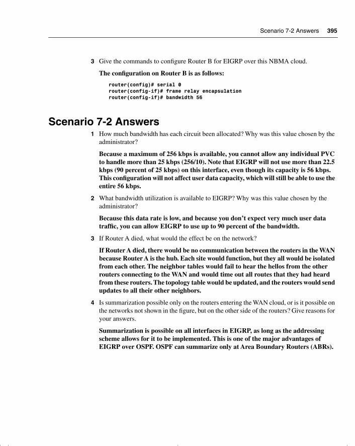
Scenario 7-2 Answers 395
3 Give the commands to configure Router B for EIGRP over this NBMA cloud.
The configuration on Router B is as follows:
router(config)# serial 0router(config-if)# frame relay encapsulationrouter(config-if)# bandwidth 56
Scenario 7-2 Answers1 How much bandwidth has each circuit been allocated? Why was this value chosen by the
administrator?
Because a maximum of 256 kbps is available, you cannot allow any individual PVC to handle more than 25 kbps (256/10). Note that EIGRP will not use more than 22.5 kbps (90 percent of 25 kbps) on this interface, even though its capacity is 56 kbps. This configuration will not affect user data capacity, which will still be able to use the entire 56 kbps.
2 What bandwidth utilization is available to EIGRP? Why was this value chosen by the administrator?
Because this data rate is low, and because you don’t expect very much user data traffic, you can allow EIGRP to use up to 90 percent of the bandwidth.
3 If Router A died, what would the effect be on the network?
If Router A died, there would be no communication between the routers in the WAN because Router A is the hub. Each site would function, but they all would be isolated from each other. The neighbor tables would fail to hear the hellos from the other routers connecting to the WAN and would time out all routes that they had heard from these routers. The topology table would be updated, and the routers would send updates to all their other neighbors.
4 Is summarization possible only on the routers entering the WAN cloud, or is it possible on the networks not shown in the figure, but on the other side of the routers? Give reasons for your answers.
Summarization is possible on all interfaces in EIGRP, as long as the addressing scheme allows for it to be implemented. This is one of the major advantages of EIGRP over OSPF. OSPF can summarize only at Area Boundary Routers (ABRs).
chpt_01.book Page 395 Thursday, December 21, 2000 6:22 PM
This chapter covers the following topics that you will need to master to pass the CCNP/CCDP Routing exam:
• The features and operation of BGP-4
• When not to use BGP-4 and the alternatives available
• How BGP-4 achieves policy-based routing within the autonomous system
• The BGP-4 peering functions
• The BGP-4 communities and peer groups
• How to configure internal BGP-4 and external BGP-4
• BGP-4 synchronization
• How to verify and troubleshoot the BGP-4 network
• Cisco commands for implementing BGP-4 and Cisco commands for reviewing the configuration.
chpt_01.book Page 396 Thursday, December 21, 2000 6:22 PM
C H A P T E R 8
Connecting to Other Autonomous Systems—The Basics of BGP-4
This chapter details Border Gateway Protocol 4 (BGP-4). Although BGP-4 is covered briefly in the ACRC exam, it is given far greater attention in the CCNP/CCDP Routing exam. Even so, the exam barely scratches the surface of the detail available to the protocol. This chapter deals with the basic concepts and configuration commands of BGP-4 and leads into greater complexity in the next chapter. This chapter builds on the understanding of routing within large enterprise networks that was dealt with previously.
This chapter is broken into two major areas. The first area of the chapter deals theoretically with how BGP-4 works. Implementing and managing a BGP-4 network is described at the end of the chapter.
The topics in this chapter directly reflect questions on the exam. BGP-4 is a routing protocol designed for use in large networks. It is a mandatory topic in the exam. The BSCN course devotes 13 percent of its material to configuring basic Border Gateway Protocol, and you can expect approximately 10 questions on the exam to be directly related to this subject.
How to Best Use This ChapterBy taking the following steps, you can make better use of your study time:
• Keep your notes and the answers for all your work with this book in one place, for easy reference.
• When you take a quiz, write down your answers. Studies show that retention significantly increases by writing down facts and concepts, even if you never look at the information again.
• Use the diagram in Figure 8-1 to guide you to the next step.
chpt_01.book Page 397 Thursday, December 21, 2000 6:22 PM
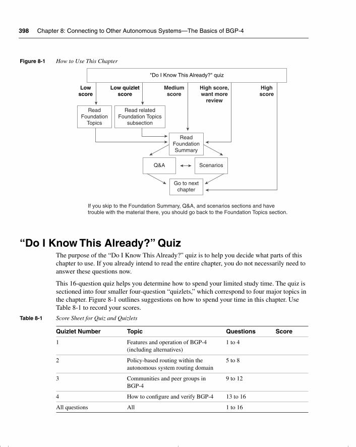
398 Chapter 8: Connecting to Other Autonomous Systems—The Basics of BGP-4
Figure 8-1 How to Use This Chapter
“Do I Know This Already?” QuizThe purpose of the “Do I Know This Already?” quiz is to help you decide what parts of this chapter to use. If you already intend to read the entire chapter, you do not necessarily need to answer these questions now.
This 16-question quiz helps you determine how to spend your limited study time. The quiz is sectioned into four smaller four-question “quizlets,” which correspond to four major topics in the chapter. Figure 8-1 outlines suggestions on how to spend your time in this chapter. Use Table 8-1 to record your scores.
Table 8-1 Score Sheet for Quiz and Quizlets
Quizlet Number Topic Questions Score
1 Features and operation of BGP-4 (including alternatives)
1 to 4
2 Policy-based routing within the autonomous system routing domain
5 to 8
3 Communities and peer groups in BGP-4
9 to 12
4 How to configure and verify BGP-4 13 to 16
All questions All 1 to 16
Lowscore
Low quizletscore
Mediumscore
High score,want more
review
Highscore
"Do I Know This Already?" quiz
ReadFoundation
Topics
Read relatedFoundation Topics
subsection
ReadFoundationSummary
Q&A Scenarios
Go to nextchapter
If you skip to the Foundation Summary, Q&A, and scenarios sections and havetrouble with the material there, you should go back to the Foundation Topics section.
chpt_01.book Page 398 Thursday, December 21, 2000 6:22 PM
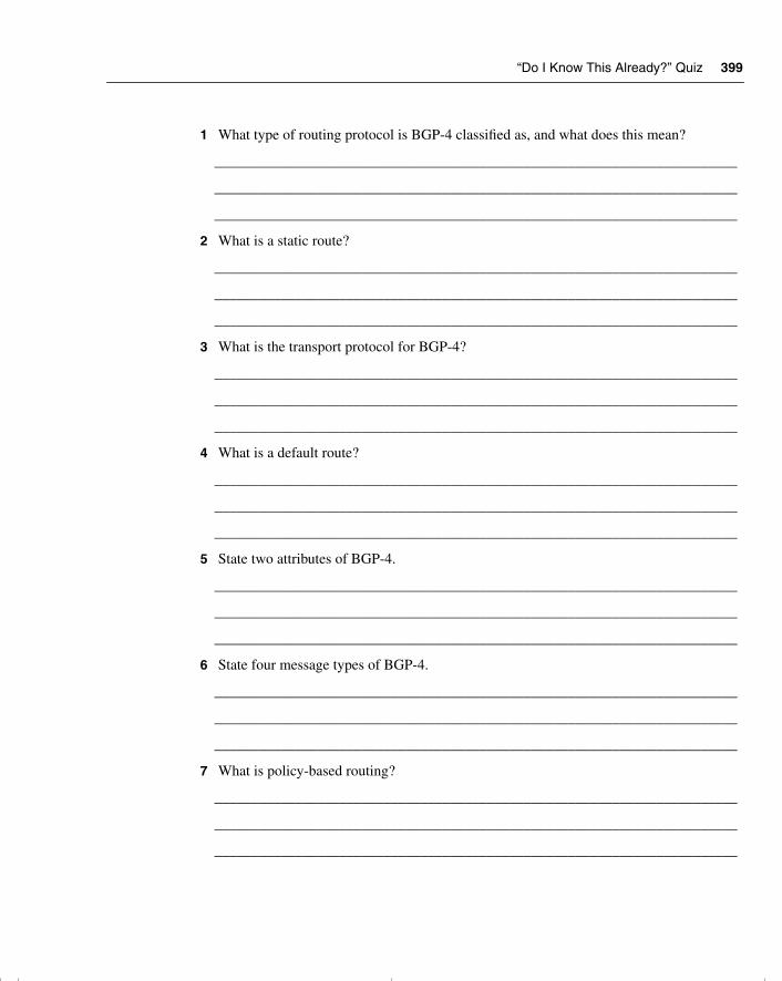
“Do I Know This Already?” Quiz 399
1 What type of routing protocol is BGP-4 classified as, and what does this mean?
_______________________________________________________________________
_______________________________________________________________________
_______________________________________________________________________
2 What is a static route?
_______________________________________________________________________
_______________________________________________________________________
_______________________________________________________________________
3 What is the transport protocol for BGP-4?
_______________________________________________________________________
_______________________________________________________________________
_______________________________________________________________________
4 What is a default route?
_______________________________________________________________________
_______________________________________________________________________
_______________________________________________________________________
5 State two attributes of BGP-4.
_______________________________________________________________________
_______________________________________________________________________
_______________________________________________________________________
6 State four message types of BGP-4.
_______________________________________________________________________
_______________________________________________________________________
_______________________________________________________________________
7 What is policy-based routing?
_______________________________________________________________________
_______________________________________________________________________
_______________________________________________________________________
chpt_01.book Page 399 Thursday, December 21, 2000 6:22 PM
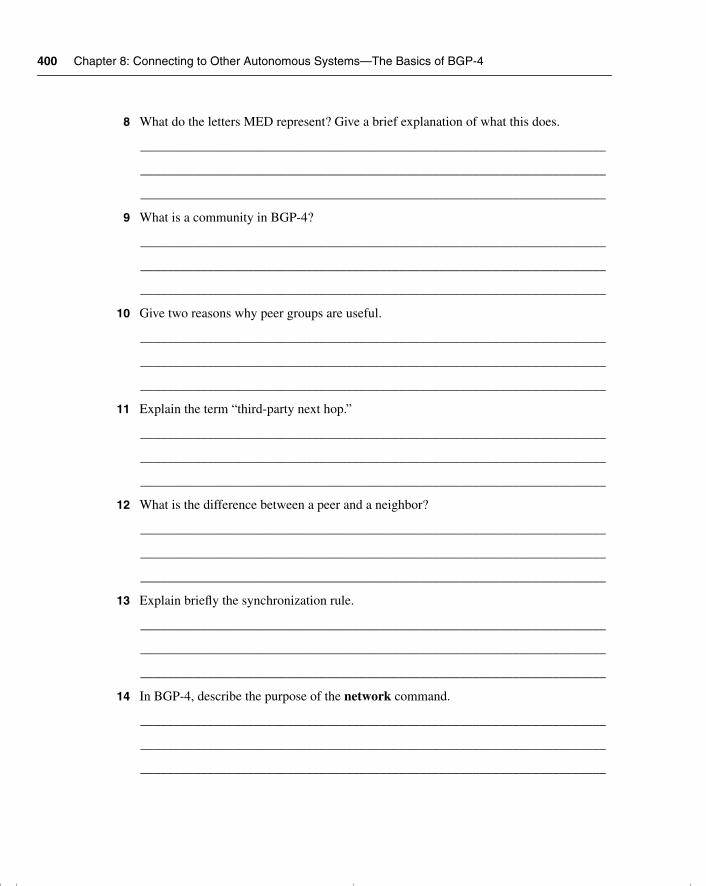
400 Chapter 8: Connecting to Other Autonomous Systems—The Basics of BGP-4
8 What do the letters MED represent? Give a brief explanation of what this does.
______________________________________________________________________
______________________________________________________________________
______________________________________________________________________
9 What is a community in BGP-4?
______________________________________________________________________
______________________________________________________________________
______________________________________________________________________
10 Give two reasons why peer groups are useful.
______________________________________________________________________
______________________________________________________________________
______________________________________________________________________
11 Explain the term “third-party next hop.”
______________________________________________________________________
______________________________________________________________________
______________________________________________________________________
12 What is the difference between a peer and a neighbor?
______________________________________________________________________
______________________________________________________________________
______________________________________________________________________
13 Explain briefly the synchronization rule.
______________________________________________________________________
______________________________________________________________________
______________________________________________________________________
14 In BGP-4, describe the purpose of the network command.
______________________________________________________________________
______________________________________________________________________
______________________________________________________________________
chpt_01.book Page 400 Thursday, December 21, 2000 6:22 PM
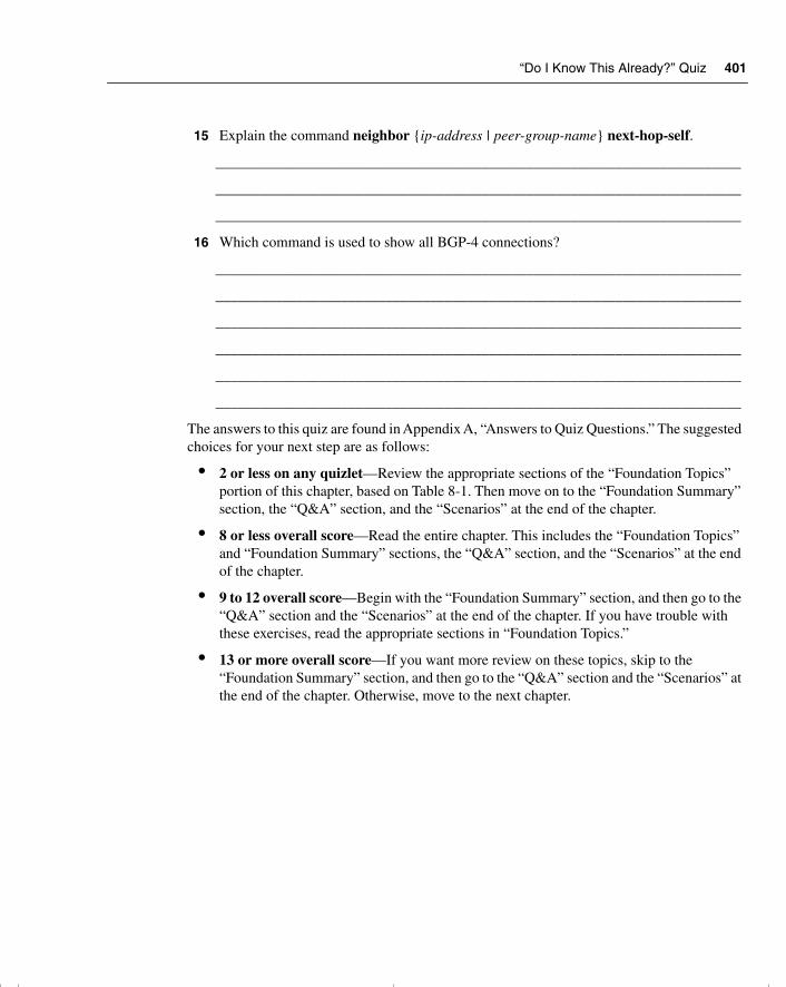
“Do I Know This Already?” Quiz 401
15 Explain the command neighbor {ip-address | peer-group-name} next-hop-self.
_______________________________________________________________________
_______________________________________________________________________
_______________________________________________________________________
16 Which command is used to show all BGP-4 connections?
_______________________________________________________________________
_______________________________________________________________________
_______________________________________________________________________
_______________________________________________________________________
_______________________________________________________________________
_______________________________________________________________________
The answers to this quiz are found in Appendix A, “Answers to Quiz Questions.” The suggested choices for your next step are as follows:
• 2 or less on any quizlet—Review the appropriate sections of the “Foundation Topics” portion of this chapter, based on Table 8-1. Then move on to the “Foundation Summary” section, the “Q&A” section, and the “Scenarios” at the end of the chapter.
• 8 or less overall score—Read the entire chapter. This includes the “Foundation Topics” and “Foundation Summary” sections, the “Q&A” section, and the “Scenarios” at the end of the chapter.
• 9 to 12 overall score—Begin with the “Foundation Summary” section, and then go to the “Q&A” section and the “Scenarios” at the end of the chapter. If you have trouble with these exercises, read the appropriate sections in “Foundation Topics.”
• 13 or more overall score—If you want more review on these topics, skip to the “Foundation Summary” section, and then go to the “Q&A” section and the “Scenarios” at the end of the chapter. Otherwise, move to the next chapter.
chpt_01.book Page 401 Thursday, December 21, 2000 6:22 PM
402 Chapter 8: Connecting to Other Autonomous Systems—The Basics of BGP-4
Foundation Topics
Introduction: BGP-4 and Communicating with other Autonomous Systems
The BSCN course deals with connectivity to the Internet via a service provider. One of the methods used to make this connection is the external routing protocol BGP-4.
The Routing 2.0 exam, recognizing that BGP-4 is increasingly important in larger environments to communicate with the Internet agent or service provider, covers a conceptual overview of BGP-4. A solid base to BGP-4 is given in addition to basic configuration commands. It is stressed however, that if your network is a simple one, using static and default routes may be configurations that are more appropriate.
Case StudyThe large multinational company Humugos has offices in 250 countries. Each country operates as a separate company, conforming to the tax and legal laws of the country. It is still important that the parts of organization be capable of connecting to one another, but EIGRP is no longer feasible for a number of reasons. The main issue is the number of connections that each country has into the Internet. There is also some need to manipulate the traffic, particularly in terms of resource sharing between business units internationally.
Figure 8-2 illustrates the network topology of the case study, Humugos.
NOTE Figure 8-2 has been simplified and does not contain the 250 autonomous systems as the case study suggests.
BGP-4 has been suggested as a solution for various reasons. First is the need for yet another level of hierarchy. Second, the multiple connections to the Internet need to be managed with a sophisticated routing protocol. The capability to determine the traffic path that will be taken by a variety of parameters is also very important. This adds another dimension to the simple metric, which proves inadequate to the task of determining subtle distinctions in path selection.
chpt_01.book Page 402 Thursday, December 21, 2000 6:22 PM
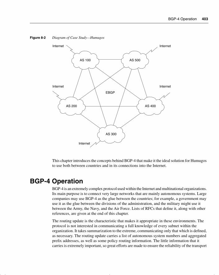
BGP-4 Operation 403
Figure 8-2 Diagram of Case Study—Humugos
This chapter introduces the concepts behind BGP-4 that make it the ideal solution for Humugos to use both between countries and in its connections into the Internet.
BGP-4 OperationBGP-4 is an extremely complex protocol used within the Internet and multinational organizations. Its main purpose is to connect very large networks that are mainly autonomous systems. Large companies may use BGP-4 as the glue between the countries; for example, a government may use it as the glue between the divisions of the administration, and the military might use it between the Army, the Navy, and the Air Force. Lists of RFCs that define it, along with other references, are given at the end of this chapter.
The routing update is the characteristic that makes it appropriate in these environments. The protocol is not interested in communicating a full knowledge of every subnet within the organization. It takes summarization to the extreme, communicating only that which is defined, as necessary. The routing update carries a list of autonomous system numbers and aggregated prefix addresses, as well as some policy routing information. The little information that it carries is extremely important, so great efforts are made to ensure the reliability of the transport
AS 100 AS 500
Internet
AS 200 AS 400
AS 300
EBGP
Internet
Internet
Internet
Internet
chpt_01.book Page 403 Thursday, December 21, 2000 6:22 PM
404 Chapter 8: Connecting to Other Autonomous Systems—The Basics of BGP-4
carrying the updates and to ensure that the databases are synchronized. This is the pinnacle of hierarchical routing design. Because of this fact, the transport medium for BGP is TCP, which provides an additional layer of reliability.
The other distinctive characteristic of BGP-4 is the concept of policy routing. Unlike interior routing protocols that just communicate all that they know about the networks within the routing domain, BGP-4 can be configured to advocate one path above another. This is done in a more sophisticated and controlled manner than can the metric afforded to the interior routing protocols.
An Autonomous System DefinedAn autonomous system is a routing domain that shares routing information. Typically, an autonomous system is the same as an organization. Within the context of internal security, every network within the organization is available, and information about the networks is transmitted via an interior routing protocol such as EIGRP, OSPF, RIP, or IGRP. Although there may be more than one interior routing protocol running within the autonomous system, the probability is that they are sharing information. This sharing is achieved through redistribution, and it allows every router within the domain awareness of every available network within the domain.
The Cisco glossary describes an autonomous system as follows:
A collection of networks under a common administration sharing a common routing strategy. An autonomous system is subdivided by areas. An autonomous system must be assigned a unique 16-bit number by IANA.
The reason for defining an autonomous system is to be able to determine the demarcation between organizations and the Internet. The capability of the Internet to identify an entire organization by the means of the unique 16-bit integer allows for great constriction of the amount of information that needs to be held in routing tables or transmitted in routing updates. This level of hierarchy is crucial to the successful operation and maintenance of the Internet.
BGP-4 is the routing protocol that is used between autonomous systems to carry this pared down information into and across the Internet. If the autonomous system is connecting directly into the Internet, then it is necessary to acquire a unique autonomous system number from the IANA. However, many organizations connect to the Internet via a service provider, who will have an autonomous system for connecting into the Internet, which includes all organizations connecting through them.
Many organizations are using BGP-4 without connecting directly to the Internet and are using private autonomous system numbers. This is done for reasons of scale and requires the same precautions as using private IP addresses.
chpt_01.book Page 404 Thursday, December 21, 2000 6:22 PM
BGP-4 Operation 405
Characteristics of BGP-4 The main characteristics of BGP-4 may be distilled into a few short points. The interaction of these components and their relative importance to the operation or design of a BGP-4 network is discussed in the rest of the chapter.
The key features of BGP-4 include these:
• It is a path vector protocol.
• Full routing updates are sent at the start of the session, trigger updates are sent subsequently.
• It creates and maintains connections between peers, using TCP port 179.
• The connection is maintained by periodic keepalives.
• The failure to see a keepalive, an update, or a notification is the means by which destination networks and paths to those destinations are tracked. Any change in the network results in a triggered update.
• The metric used in BGP-4 is intricate and is the source of its complexity and its strength. The metric, referred to as attributes, allows great granularity in path selection.
• The use of hierarchical addressing and the capability to manipulate traffic flow results in a network that is designed to grow.
• It has its own routing table, although it is capable of both sharing and inquiring of the interior IP routing table.
• It is possible to manipulate the traffic flow by using the complex metric called attributes, but policy-based routing is based on the hop-by-hop paradigm. This means that no router can send traffic on a route that the next-hop router would not choose for itself.
How BGP-4 works and an explanation of some of these characteristics are given in the following section.
Overview of the BGP-4 OperationBGP-4 is connection-oriented. When a neighbor is seen, a TCP peering session is established and maintained. BGP-4 probes are sent out periodically to sustain the link and maintain the session. These probes, otherwise known as keepalives, are simply the 19 byte header used in the BGP updates.
Having established the session, the routing tables are exchanged and synchronized. The routers now send incremental updates only when changes occur. The update refers to a single path and the networks that may be reached via that path. Having corrected the routing table, the BGP-4 process propagates the change to all neighbors, with a few exceptions, based on an algorithm to ensure a loop-free network.
chpt_01.book Page 405 Thursday, December 21, 2000 6:22 PM
406 Chapter 8: Connecting to Other Autonomous Systems—The Basics of BGP-4
The establishment of a BGP-4 peer is shown in Figure 8-3.
The operation of BGP-4 is very straightforward. Indeed, all the complexity of the protocol is delivered in only a few different types of routing packets.
Message TypesFour different message types are used in BGP-4:
• Open messages—Used to establish connections with peers.
• Keepalives—Sent periodically between peers to maintain connections and verify paths held by the router sending the keepalive. These packets are sent unreliably. If the periodic timer is set to a value of 0, this equates to infinity, and no keepalives are sent.
• Update messages—Contain paths to destination networks and the path attributes. Routes that are no longer available or withdrawn routes are included in updates. There is one path per update, requiring many updates for many paths. The information contained in the update includes the path attributes such as origin, Autonomous System path, neighbor, and inter-Autonomous System metric.
• Notification—Used to inform the receiving router of errors.
BGP-4 comes in two flavors: internal and external BGP-4. The difference depends on the function of the routing protocol. The router will determine if the peer BGP-4 router is going to be an external BGP-4 peer or an internal BGP-4 peer by checking the autonomous system number in the open message that was sent.
Internal BGP-4 is used within an autonomous system. It conveys information to all BGP-4 routers within the domain and ensures that they have a consistent understanding of the networks available. Internal BGP-4 is used within an ISP or a large organization to coordinate the knowledge of that autonomous system. The routers are not required to be physical neighbors on the same medium, and they often sit on the edges of the network. Internal BGP-4 is used to convey BGP-4 information about other autonomous systems across a transit autonomous system. Another routing protocol, an interior routing protocol such as OSPF, is used to route the BGP-4 packets to their remote locations. To achieve this, internal BGP requires the destination BGP neighbor’s IP address to be contained within the normal routing table kept by another routing protocol (static routing, OSPF, EIGRP, and so on). The integration of these different routing protocols can be challenging.
External BGP-4 complies with the common perception of an external routing protocol; it sends routing information between differing autonomous systems. Therefore, the border router between different autonomous systems is the external BGP router. Figure 8-4 shows the application of internal and external BGP-4.
chpt_01.book Page 406 Thursday, December 21, 2000 6:22 PM
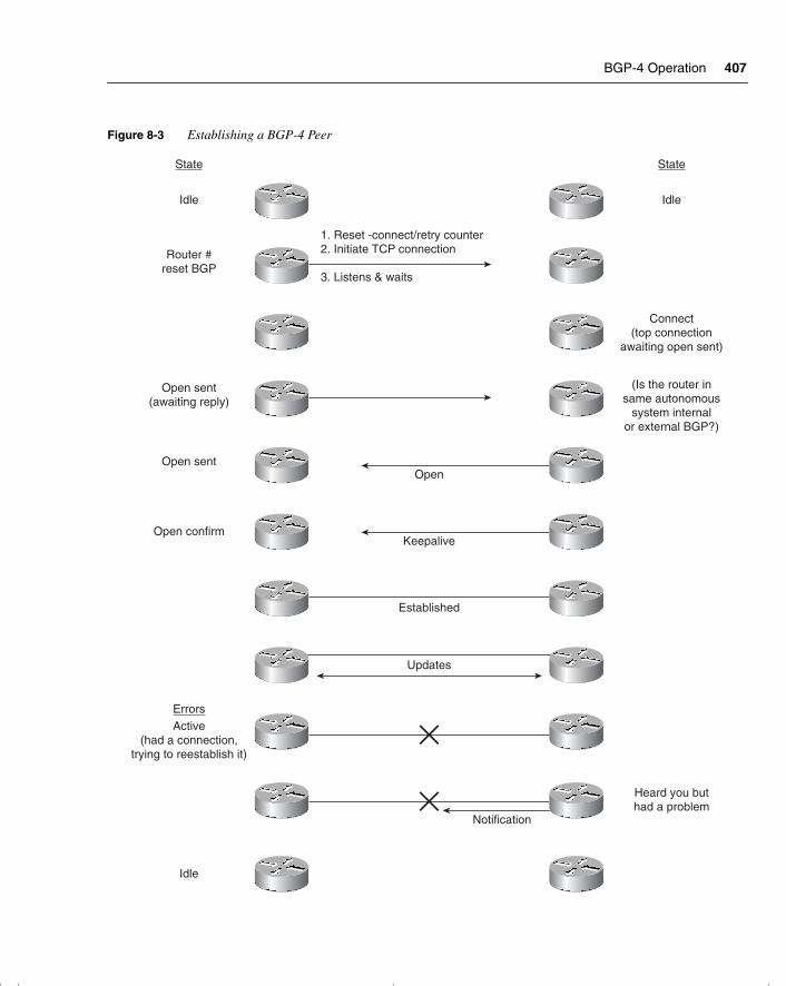
BGP-4 Operation 407
Figure 8-3 Establishing a BGP-4 Peer
State
Errors
State
Idle
Router #reset BGP
Idle
Connect(top connection
awaiting open sent)
(Is the router insame autonomous
system internalor external BGP?)
1. Reset -connect/retry counter2. Initiate TCP connection
3. Listens & waits
Open sent(awaiting reply)
Open sentOpen
Keepalive
Established
Updates
Open confirm
Heard you buthad a problem
Active(had a connection,
trying to reestablish it)
Idle
Notification
chpt_01.book Page 407 Thursday, December 21, 2000 6:22 PM
408 Chapter 8: Connecting to Other Autonomous Systems—The Basics of BGP-4
Synchronization A simple rule states that before IBGP-4 can propagate a route into another autonomous system handing it over to EBGP-4, the route must be totally known within the autonomous system. That is to say that the Internal Gateway Protocol (IGP) or internal routing protocol must be synchronized with BGP-4.
This is to ensure that if traffic is sent into the autonomous system, the interior routing protocol can direct it to its destination. It makes sense that this rule is on by default and should be turned off only if all routers in the autonomous system are running BGP-4. Likewise, although it is not referred to as synchronization, this case also applies for IBGP connections. If the IBGP routers are not physically connected, the IGP needs to be capable of routing the updates to the BGP-4 peer.
The synchronization rule is illustrated in Figure 8-5.
Benefits of the Synchronization RuleThe following list gives reasons for the synchronization rule:
• It prevents traffic from being forwarded to unreachable destinations.
• It reduces unnecessary traffic.
• It ensures consistency within the autonomous system.
On some occasions it is useful to turn off synchronization. This is rare, and, as with any default, it is unwise to turn off this option without a detailed understanding of the network. The occasions when it may be useful to turn off synchronization are as follows:
• If all the routers in the autonomous system are running BGP-4.
• If all the routers inside the autonomous system are meshed.
• When the autonomous system is not a transit domain. A transit domain is an autonomous system that is used to carry BGP-4 updates from one autonomous system to another.
chpt_01.book Page 408 Thursday, December 21, 2000 6:22 PM
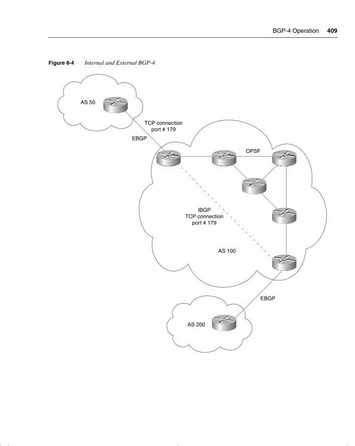
BGP-4 Operation 409
Figure 8-4 Internal and External BGP-4
AS 50
TCP connectionport # 179
EBGP
EBGP
AS 200
OPSF
IBGPTCP connection
port # 179
AS 100
chpt_01.book Page 409 Thursday, December 21, 2000 6:22 PM
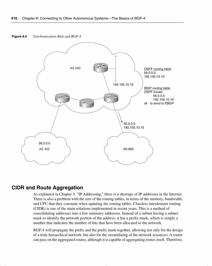
410 Chapter 8: Connecting to Other Autonomous Systems—The Basics of BGP-4
Figure 8-5 Synchronization Rule and BGP-4
CIDR and Route AggregationAs explained in Chapter 3, “IP Addressing,” there is a shortage of IP addresses in the Internet. There is also a problem with the size of the routing tables, in terms of the memory, bandwidth, and CPU that they consume when updating the routing tables. Classless interdomain routing (CIDR) is one of the main solutions implemented in recent years. This is a method of consolidating addresses into a few summary addresses. Instead of a subnet having a subnet mask to identify the network portion of the address, it has a prefix mask, which is simply a number that indicates the number of bits that have been allocated to the network.
BGP-4 will propagate the prefix and the prefix mask together, allowing not only for the design of a truly hierarchical network, but also for the streamlining of the network resources. A router can pass on the aggregated routes, although it is capable of aggregating routes itself. Therefore,
AS 800
AS 200
AS 400
192.100.10.10
OSPF routing table56.0.0.0192.100.10.10
56.0.0.0192.100.10.10
56.0.0.0
IBGP routing tableOSPF knows
56.0.0.0192.100.10.10
ok to send to EBGP
chpt_01.book Page 410 Thursday, December 21, 2000 6:22 PM
BGP-4 Operation 411
a router can send either aggregated routes, routes that have not been summarized, or a mixture of both.
The process of how BGP-4 aggregates routes in compliance to CIDR is shown in the Figure 8-6.
Several attributes are connected to the use of address aggregation in BGP-4. Table 8-2 covers some of these attributes.
BGP-4 Policy-Based RoutingPolicy-based routing gives the administrator the ability to define how traffic will be routed at the autonomous system level. This is a level of control above the dynamic routing protocol. Given that many variables in BGP-4 can influence dynamic routing (these are called variables), this is a very high level of control. This other dimension distinguishes BGP-4 from other routing protocols.
Policy-based routing is a form of static routing enforced by specialized access lists called route maps.
Rules of Policy RoutingSome rules are associated with Policy routing. The following rules seem repetitive, but, in fact, each point raises a subtly different nuance:
Table 8-2 Route Aggregation Attributes
Attribute Type of Attribute Description of Attribute
Atomic aggregate Well known, discretionary This is the default attribute. The originator of the aggregate route is stated. It is useful because it shows that some information has been lost due to the aggregation of routes. It states to the receiving router in another autonomous system that the originator of the route aggregated the routes.
Aggregator Optional, transitive This attribute gives the router ID and the autonomous system of the router that performed the aggregation.
AS_Path Well known, mandatory This attribute can include a list of all the autonomous systems that the aggregated routes have passed through.
chpt_01.book Page 411 Thursday, December 21, 2000 6:22 PM
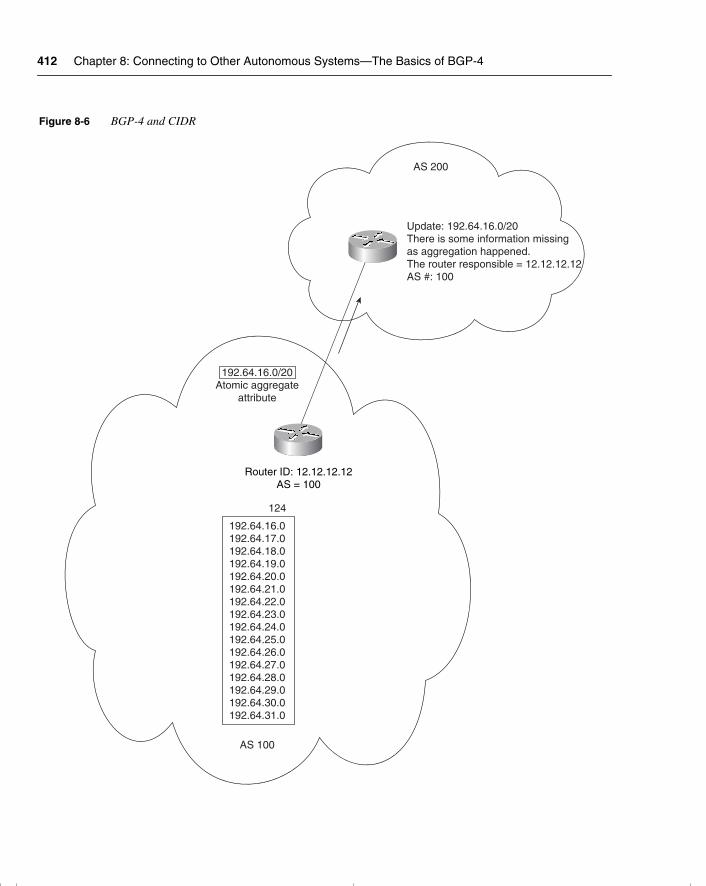
412 Chapter 8: Connecting to Other Autonomous Systems—The Basics of BGP-4
Figure 8-6 BGP-4 and CIDR
192.64.16.0/20Atomic aggregate
attribute
AS 100
Router ID: 12.12.12.12AS = 100
192.64.16.0192.64.17.0192.64.18.0192.64.19.0192.64.20.0192.64.21.0192.64.22.0192.64.23.0192.64.24.0192.64.25.0192.64.26.0192.64.27.0192.64.28.0192.64.29.0192.64.30.0192.64.31.0
124
Update: 192.64.16.0/20There is some information missingas aggregation happened.The router responsible = 12.12.12.12AS #: 100
AS 200
chpt_01.book Page 412 Thursday, December 21, 2000 6:22 PM
BGP-4 Operation 413
• Traffic can be directed on either the source address or both the source and destination addresses.
• Policy routing affects only the next hop in the path to the destination.
• Policy routing does not affect the destination of the packet. It affects the path used to get to the destination.
• Policy routing does not allow traffic sent into another autonomous system to take a different path from the one that would have been chosen by that autonomous system.
• It is possible to influence only how traffic will get to a neighboring autonomous system, not how it will be routed within that autonomous system.
• BGP-4 can implement any rule associated to the hop-by-hop paradigm. That is the capability to influence which router will be the next-hop router, potentially dictating this at every router and thus influencing the entire path of the traffic, hop by hop.
• As policy routing examines the source address, it is configured on the inbound interface.
Disadvantages of Policy RoutingSome things should be considered before arbitrarily deciding to implement policy routing:
• A backup path should be in place in case the defined next-hop router goes down. If there is no alternative defined, policy routing will default to dynamic routing decisions.
• Additional CPU is required to examine every source address to effect the defined policy.
• Extra configuration is required.
• The possibility exists that other traffic will be disrupted.
BGP-4’s capability to choose the routing path via conditional programming was used for policy routing in other situations before it became an option in the Cisco IOS. BGP-4 was deployed in some situations to use the policy routing options; for example, it was used by the two early deployments of tag routing as the only means of programming policy routing. This is a powerful tool and can be used in many situations, such as forcing traffic entering your routing domain to pass through the firewall or in a situation in which there are multiple connections to the Internet, load balancing among those connections. Refer to Figure 8-7 for an example of how policy routing could be implemented.
In Router A in Figure 8-7, the traffic from 192.17.50.6 network is from the graphic design department. It is high-volume, sensitive traffic; therefore, you should send it on a path dedicated to such traffic—always direct it to Router C.
chpt_01.book Page 413 Thursday, December 21, 2000 6:22 PM
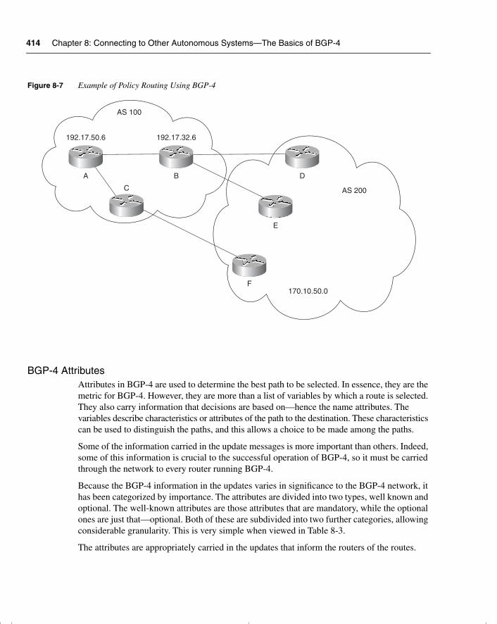
414 Chapter 8: Connecting to Other Autonomous Systems—The Basics of BGP-4
Figure 8-7 Example of Policy Routing Using BGP-4
BGP-4 AttributesAttributes in BGP-4 are used to determine the best path to be selected. In essence, they are the metric for BGP-4. However, they are more than a list of variables by which a route is selected. They also carry information that decisions are based on—hence the name attributes. The variables describe characteristics or attributes of the path to the destination. These characteristics can be used to distinguish the paths, and this allows a choice to be made among the paths.
Some of the information carried in the update messages is more important than others. Indeed, some of this information is crucial to the successful operation of BGP-4, so it must be carried through the network to every router running BGP-4.
Because the BGP-4 information in the updates varies in significance to the BGP-4 network, it has been categorized by importance. The attributes are divided into two types, well known and optional. The well-known attributes are those attributes that are mandatory, while the optional ones are just that—optional. Both of these are subdivided into two further categories, allowing considerable granularity. This is very simple when viewed in Table 8-3.
The attributes are appropriately carried in the updates that inform the routers of the routes.
AS 200
AS 100
170.10.50.0
192.17.50.6 192.17.32.6
A B
C
D
E
F
chpt_01.book Page 414 Thursday, December 21, 2000 6:22 PM
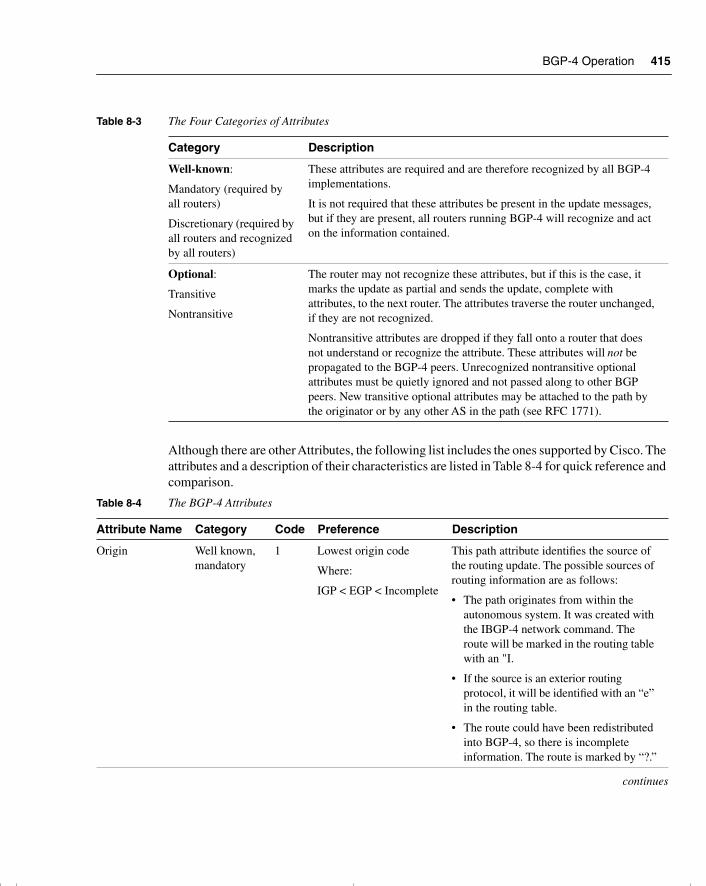
BGP-4 Operation 415
Although there are other Attributes, the following list includes the ones supported by Cisco. The attributes and a description of their characteristics are listed in Table 8-4 for quick reference and comparison.
Table 8-3 The Four Categories of Attributes
Category Description
Well-known:
Mandatory (required by all routers)
Discretionary (required by all routers and recognized by all routers)
These attributes are required and are therefore recognized by all BGP-4 implementations.
It is not required that these attributes be present in the update messages, but if they are present, all routers running BGP-4 will recognize and act on the information contained.
Optional:
Transitive
Nontransitive
The router may not recognize these attributes, but if this is the case, it marks the update as partial and sends the update, complete with attributes, to the next router. The attributes traverse the router unchanged, if they are not recognized.
Nontransitive attributes are dropped if they fall onto a router that does not understand or recognize the attribute. These attributes will not be propagated to the BGP-4 peers. Unrecognized nontransitive optional attributes must be quietly ignored and not passed along to other BGP peers. New transitive optional attributes may be attached to the path by the originator or by any other AS in the path (see RFC 1771).
Table 8-4 The BGP-4 Attributes
Attribute Name Category Code Preference Description
Origin Well known, mandatory
1 Lowest origin code
Where:
IGP < EGP < Incomplete
This path attribute identifies the source of the routing update. The possible sources of routing information are as follows:
• The path originates from within the autonomous system. It was created with the IBGP-4 network command. The route will be marked in the routing table with an "I.
• If the source is an exterior routing protocol, it will be identified with an “e” in the routing table.
• The route could have been redistributed into BGP-4, so there is incomplete information. The route is marked by “?.”
continues
chpt_01.book Page 415 Thursday, December 21, 2000 6:22 PM
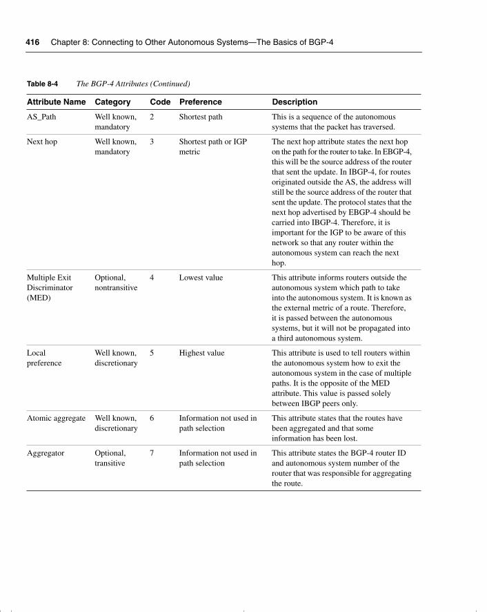
416 Chapter 8: Connecting to Other Autonomous Systems—The Basics of BGP-4
AS_Path Well known, mandatory
2 Shortest path This is a sequence of the autonomous systems that the packet has traversed.
Next hop Well known, mandatory
3 Shortest path or IGP metric
The next hop attribute states the next hop on the path for the router to take. In EBGP-4, this will be the source address of the router that sent the update. In IBGP-4, for routes originated outside the AS, the address will still be the source address of the router that sent the update. The protocol states that the next hop advertised by EBGP-4 should be carried into IBGP-4. Therefore, it is important for the IGP to be aware of this network so that any router within the autonomous system can reach the next hop.
Multiple Exit Discriminator (MED)
Optional, nontransitive
4 Lowest value This attribute informs routers outside the autonomous system which path to take into the autonomous system. It is known as the external metric of a route. Therefore, it is passed between the autonomous systems, but it will not be propagated into a third autonomous system.
Local preference
Well known,discretionary
5 Highest value This attribute is used to tell routers within the autonomous system how to exit the autonomous system in the case of multiple paths. It is the opposite of the MED attribute. This value is passed solely between IBGP peers only.
Atomic aggregate Well known,discretionary
6 Information not used in path selection
This attribute states that the routes have been aggregated and that some information has been lost.
Aggregator Optional, transitive
7 Information not used in path selection
This attribute states the BGP-4 router ID and autonomous system number of the router that was responsible for aggregating the route.
Table 8-4 The BGP-4 Attributes (Continued)
Attribute Name Category Code Preference Description
chpt_01.book Page 416 Thursday, December 21, 2000 6:22 PM
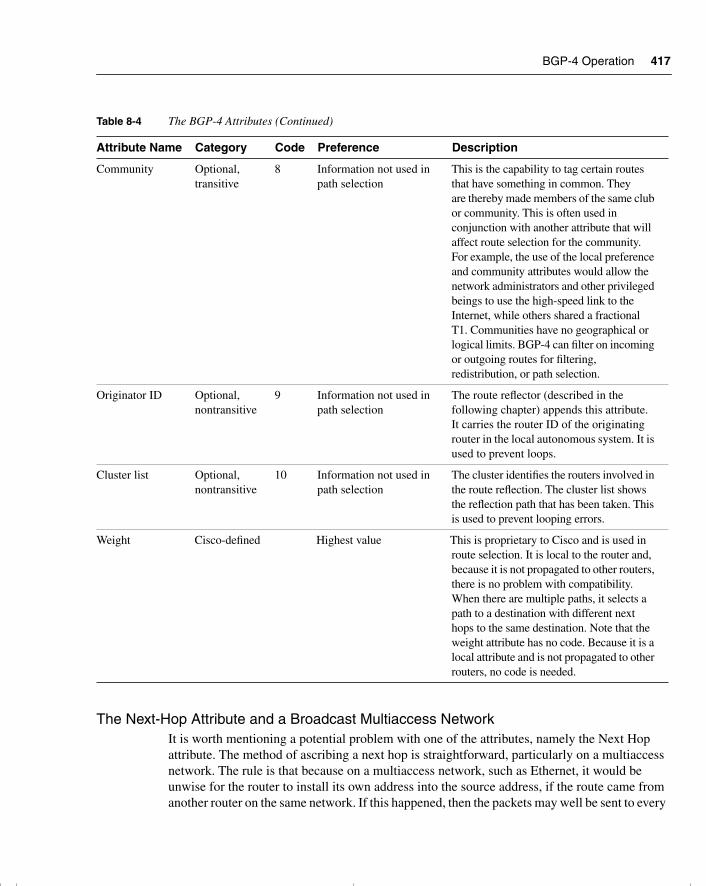
BGP-4 Operation 417
The Next-Hop Attribute and a Broadcast Multiaccess NetworkIt is worth mentioning a potential problem with one of the attributes, namely the Next Hop attribute. The method of ascribing a next hop is straightforward, particularly on a multiaccess network. The rule is that because on a multiaccess network, such as Ethernet, it would be unwise for the router to install its own address into the source address, if the route came from another router on the same network. If this happened, then the packets may well be sent to every
Community Optional, transitive
8 Information not used in path selection
This is the capability to tag certain routes that have something in common. They are thereby made members of the same club or community. This is often used in conjunction with another attribute that will affect route selection for the community. For example, the use of the local preference and community attributes would allow the network administrators and other privileged beings to use the high-speed link to the Internet, while others shared a fractional T1. Communities have no geographical or logical limits. BGP-4 can filter on incoming or outgoing routes for filtering, redistribution, or path selection.
Originator ID Optional, nontransitive
9 Information not used in path selection
The route reflector (described in the following chapter) appends this attribute. It carries the router ID of the originating router in the local autonomous system. It is used to prevent loops.
Cluster list Optional, nontransitive
10 Information not used in path selection
The cluster identifies the routers involved in the route reflection. The cluster list shows the reflection path that has been taken. This is used to prevent looping errors.
Weight Cisco-defined Highest value This is proprietary to Cisco and is used in route selection. It is local to the router and, because it is not propagated to other routers, there is no problem with compatibility. When there are multiple paths, it selects a path to a destination with different next hops to the same destination. Note that the weight attribute has no code. Because it is a local attribute and is not propagated to other routers, no code is needed.
Table 8-4 The BGP-4 Attributes (Continued)
Attribute Name Category Code Preference Description
chpt_01.book Page 417 Thursday, December 21, 2000 6:22 PM
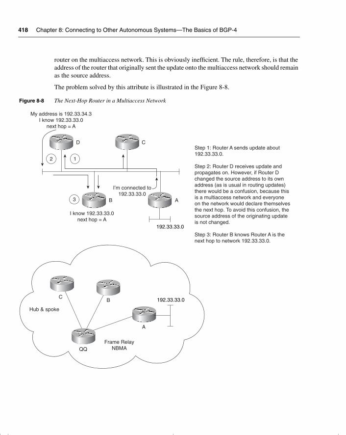
418 Chapter 8: Connecting to Other Autonomous Systems—The Basics of BGP-4
router on the multiaccess network. This is obviously inefficient. The rule, therefore, is that the address of the router that originally sent the update onto the multiaccess network should remain as the source address.
The problem solved by this attribute is illustrated in the Figure 8-8.
Figure 8-8 The Next-Hop Router in a Multiaccess Network
Frame RelayNBMA
A
BC 192.33.33.0
192.33.33.0
Hub & spoke
D C
B A
My address is 192.33.34.3I know 192.33.33.0
next hop = A
I know 192.33.33.0next hop = A
I’m connected to192.33.33.0
2 1
3
Step 1: Router A sends update about 192.33.33.0.
Step 2: Router D receives update and propagates on. However, if Router D changed the source address to its own address (as is usual in routing updates) there would be a confusion, because this is a multiaccess network and everyone on the network would declare themselvesthe next hop. To avoid this confusion, the source address of the originating update is not changed.
Step 3: Router B knows Router A is the next hop to network 192.33.33.0.
chpt_01.book Page 418 Thursday, December 21, 2000 6:22 PM
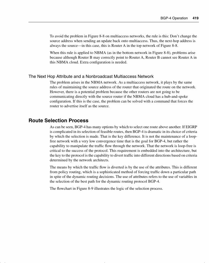
BGP-4 Operation 419
To avoid the problem in Figure 8-8 on multiaccess networks, the rule is this: Don’t change the source address when sending an update back onto multiaccess. Thus, the next-hop address is always the source—in this case, this is Router A in the top network of Figure 8-8.
When this rule is applied to NBMA (as in the bottom network in Figure 8-8), problems arise because although Router B may correctly point to Router A, Router B cannot see Router A in this NBMA cloud. Extra configuration is needed.
The Next Hop Attribute and a Nonbroadcast Multiaccess NetworkThe problem arises in the NBMA network. As a multiaccess network, it plays by the same rules of maintaining the source address of the router that originated the route on the network. However, there is a potential problem because the other routers are not going to be communicating directly with the source router if the NBMA cloud has a hub-and-spoke configuration. If this is the case, the problem can be solved with a command that forces the router to advertise itself as the source.
Route Selection ProcessAs can be seen, BGP-4 has many options by which to select one route above another. If EIGRP is complicated in its selection of feasible routes, then BGP-4 is dramatic in its choice of criteria by which the selection is made. That is the key difference. It is not the maintenance of a loop-free network with a very low convergence time that is the goal for BGP-4, but rather the capability to manipulate the traffic flow through the network. That the network is loop-free is critical to the success of the protocol. This requirement is embedded into the architecture, but the key to the protocol is the capability to divert traffic into different directions based on criteria determined by the network architects.
The means by which the traffic flow is diverted is by the use of the attributes. This is different from policy routing, which is a sophisticated method of forcing traffic down a particular path in spite of the dynamic routing decisions. The use of attributes refers to the use of variables in the selection of the best path for the dynamic routing protocol BGP-4.
The flowchart in Figure 8-9 illustrates the logic of the selection process.
chpt_01.book Page 419 Thursday, December 21, 2000 6:22 PM
420 Chapter 8: Connecting to Other Autonomous Systems—The Basics of BGP-4
Figure 8-9 Path Selection in BGP-4
Routing table
NetXXXX
NMXXXX
MetricXXXX
Do multiple paths havethe same weight?
Is the path accessible?Yes
Is synchronization on?Yes No
NoIs the route
synchronized?
Is the next-hoprouter available?
Yes
No
Considerattributes
Do they have the samelocal preference?
Is one of the pathsoriginated by this router?
Are the AS-pathsthe same length?
Is the origin codethe same?
Is the MED valuethe same?
Is one of the pathsfrom EBGP?
Is one ofthe paths to the next hop
router shorter?
Select the lowestBGP-4 router ID
Paths are equal
No
Yes
Yes
Yes
No
YesPick EBGP path
NoPick lowest value
NoPick lowest origin code
NoPick the shortest AS-path
YesPick route
NoPick highest L.P.
NoPick highest weight
Yes
Yes
Yes
YesPick shortest path
No
Incomingpacket
Trash
chpt_01.book Page 420 Thursday, December 21, 2000 6:22 PM
Basic Configuration Commands to Connect to Another Autonomous System 421
The following process further illustrates the logic of the selection process:
1 If the router has a valid route to the destination, use that route.
2 If there is more than one valid route to the destination, take the route with the highest weight (Cisco proprietary).
3 If the weights are the same, then select the route with the highest local preference.
4 If the routes have the same local preference, then prefer the route that originated on that router.
5 If there are no routes that originated on the router, then examine the AS_Path and select the shortest path.
6 If the AS_Path is the same, then examine and choose the lowest origin code.
7 If the origin codes are the same, then select the path with the lowest MED (the MED values must have been sent from the same neighboring autonomous system).
8 If the MED values are the same, then choose an external BGP-4 route above an internal BGP-4 route.
9 If there is no external route, then choose the shortest path to the next-hop router for IBGP-4.
10 If all else fails, then choose the router with the lowest BGP-4 router ID.
NOTE The preceding is a simplification of the selection process. For more detailed information on how the routing decisions are made, refer to RFC 1771, “A Border Gateway Protocol 4 (BGP-4).”
This document, together with its companion document, RFC 1772, “Application of the Border Gateway Protocol in the Internet,” defines an interautonomous system routing protocol for the Internet.
Basic Configuration Commands to Connect to Another Autonomous System
To connect to another autonomous system, it is necessary to configure the following:
• The start of the routing process
• The networks to be advertised
• The BGP-4 neighbor that the routing process will be synchronizing routing tables with over a TCP session
chpt_01.book Page 421 Thursday, December 21, 2000 6:22 PM
422 Chapter 8: Connecting to Other Autonomous Systems—The Basics of BGP-4
Starting the Routing ProcessThe command to configure the routing process is the same command as seen for the interior routing protocols. The syntax is as follows:
router bgp autonomous system number
Defining the Networks to Be AdvertisedTo define the network that is to be advertised for this autonomous system, the following command is used (each network requires a separate command):
network network-number mask network-mask
The network command determines the networks that are originated by this router. This is a different use of the command that you are accustomed to configuring with EIGRP, OSPF, and RIP. This command is not identifying the interfaces upon which to run BGP; instead, it is stating the networks that are to be advertised by BGP. The network command must include all the networks in the autonomous system to be advertised, not just those that are directly connected to the router. The mask portion is used because BGP-4 can handle subnetting and supernetting.
Identifying Neighbors and Defining Peer GroupsIn internal BGP-4, the remote autonomous system number that is defined for the BGP-4 peer will be the same; in external BGP-4, these numbers will differ. The syntax is as follows:
neighbor ip-address | peer-group-name remote-as autonomous system number
The use of the peer-group-name allows the identification of this router as a member of a peer group.
A peer group is a group of neighbors that share the same update policy. This is the mechanism by which routers can be grouped to simplify configuration.
Forcing the Next-Hop AddressOn a multiaccess network, the rule is that the source address of a packet is that of the router that originated the packet onto the network. This can cause problems on a NBMA network that appears to be a multiaccess network but that in reality may not have full connectivity to all the routers on the network. If the source address is the address of the initiating router, the other routers may not have a path to this next hop, and packets will be dropped. To overcome this problem, the next-hop address can be configured to be that of the transmitting router. The syntax of the command is as follows:
neighbor {ip-address | peer-group} next-hop-self
This issue is described earlier in this chapter, in the section “The Next-Hop Attribute and a Broadcast Multiaccess Network.”
chpt_01.book Page 422 Thursday, December 21, 2000 6:22 PM
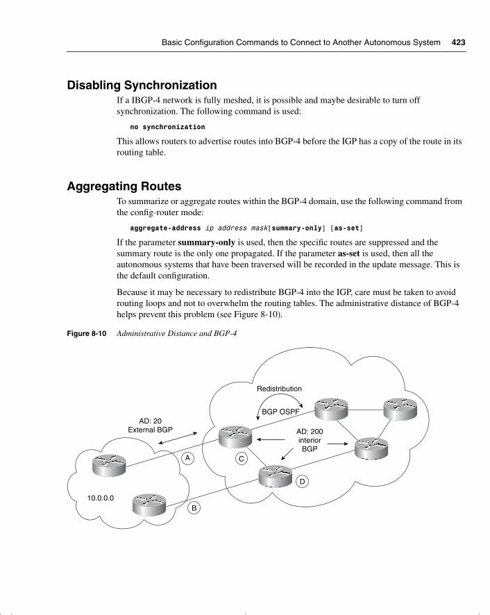
Basic Configuration Commands to Connect to Another Autonomous System 423
Disabling SynchronizationIf a IBGP-4 network is fully meshed, it is possible and maybe desirable to turn off synchronization. The following command is used:
no synchronization
This allows routers to advertise routes into BGP-4 before the IGP has a copy of the route in its routing table.
Aggregating RoutesTo summarize or aggregate routes within the BGP-4 domain, use the following command from the config-router mode:
aggregate-address ip address mask[summary-only] [as-set]
If the parameter summary-only is used, then the specific routes are suppressed and the summary route is the only one propagated. If the parameter as-set is used, then all the autonomous systems that have been traversed will be recorded in the update message. This is the default configuration.
Because it may be necessary to redistribute BGP-4 into the IGP, care must be taken to avoid routing loops and not to overwhelm the routing tables. The administrative distance of BGP-4 helps prevent this problem (see Figure 8-10).
Figure 8-10 Administrative Distance and BGP-4
AD: 20External BGP
10.0.0.0
A
B
C
D
AD: 200interiorBGP
Redistribution
BGP OSPF
chpt_01.book Page 423 Thursday, December 21, 2000 6:22 PM
424 Chapter 8: Connecting to Other Autonomous Systems—The Basics of BGP-4
In Figure 8-10, because BGP-4 (internal) has an administrative distance of 200, it is effectively the last choice. Router C will always choose the direct path to 10.0.0.0 through Router A because it has an administrative distance of 20. The route through D and B to find network 10.0.0.0 will have an administrative distance of 110 or 200, depending on the configuration.
Managing and Verifying the BGP-4 ConfigurationAfter configuration changes in BGP-4, it is necessary to reset the TCP session between neighbors. This can be forced with the following command:
clear ip bgp {* | address}[soft [in | out]]
This command disconnects the session between the neighbors and re-establishes it using the new configuration that has been entered. The soft option does not tear down the sessions, but it resends the updates. The in and out options allow the configuration of inbound or outbound soft updates. The default is for both.
NOTE The clear ip bgp command is an executive command executed at the privileged level. It is not a configuration command.
The show commands for BGP-4 are comprehensive and give clear information about the BGP-4 sessions and routing options. These informative commands and their functions are as follows:
• show ip bgp—Displays the BGP routing table.
• show ip bgp paths—Displays the topology table.
• show ip bgp summary—Displays information about the TCP sessions.
• show ip bgp neighbors—Displays information about the TCP connections to neighbors. When the connection is established, the neighbors can exchange updates.
Another command that helps to troubleshoot any implementation and that should be considered in the BGP-4 configuration is the debug command. An entire book in the IOS documentation set is devoted to this command. For BGP-4, debug is a very useful command. It is shown here with all the possible options:
• debug ip bgp [dampening | events | keepalives | updates]—This command displays live information of events as they occur. The options available display events, routing updates as they are sent or received, keepalives to maintain the TCP session with the peer, and dampening information.
Given its complexity and role in internetworking, BGP-4 is very seldom used by private organizations. Despite the rush to connect to the expanding Internet resources, service
chpt_01.book Page 424 Thursday, December 21, 2000 6:22 PM
When Not to Use BGP-4 425
providers have emerged to set up and manage the connection. This is advantageous to everyone. For a small fee, the organization or individual has a complex connection created and maintained; the Internet’s burden is also eased because it is still dealing with large corporations and organizations rather than the millions of individual users.
For this reason, the information on troubleshooting BGP-4 is not broken into as much detail as has been done in previous chapters for other technologies.
When to Use BGP-4Although the alternatives to BGP-4 are preferred for their simple connections to the Internet, on some occasions it is advantageous to use the power of this complex protocol. These reasons to use BGP-4 include the following:
• Your organization is connecting to multiple ISPs or autonomous systems and is actively using those links. Many organizations use this for redundancy purposes, justifying the additional cost by using all the links and reducing bottlenecks and congestion. In this case, policy routing decisions may need to be made on a link-by-link basis.
• The routing policy of the ISP and your company differ. The cost of the link depends on usage; time of day and other factors may need to be programmed into the BGP-4 configuration to make the best use of the connection by manipulating the traffic.
• The traffic in your organization needs to be distinguished from that of the ISP. They cannot logically appear as one autonomous system.
• Your organization is an ISP and, therefore, conforms to all of the previous criteria. The nature of your business requires the traffic from other autonomous systems to travel across your autonomous system, treating it as a transit domain.
When Not to Use BGP-4It is a truism that a simple network is a network that is easier to manage and maintain, which is the main reason to avoid BGP-4 configuration in the network. Therefore, if your network has the following characteristics, use other methods, such as static and default routing, to achieve connectivity to the ISP or to another autonomous system network:
• The ISP and your organization have the same routing policy.
• Although your company has multiple links to the ISP, these links are redundant and there are no plans to activate more than one link to the Internet.
• There are limited network resources, such as memory and CPU, on the routers.
• The bandwidth between the autonomous system is low, and the additional routing overhead would detract from routing data.
• You lack confidence or expertise in BGP-4 and route filtering.
chpt_01.book Page 425 Thursday, December 21, 2000 6:22 PM
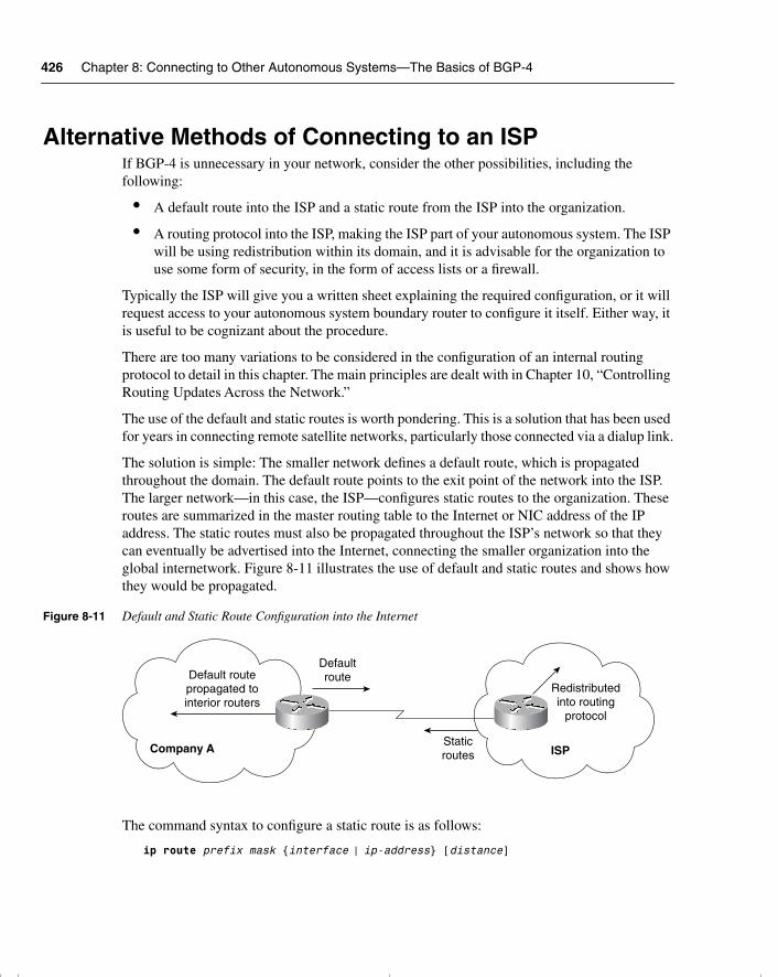
426 Chapter 8: Connecting to Other Autonomous Systems—The Basics of BGP-4
Alternative Methods of Connecting to an ISPIf BGP-4 is unnecessary in your network, consider the other possibilities, including the following:
• A default route into the ISP and a static route from the ISP into the organization.
• A routing protocol into the ISP, making the ISP part of your autonomous system. The ISP will be using redistribution within its domain, and it is advisable for the organization to use some form of security, in the form of access lists or a firewall.
Typically the ISP will give you a written sheet explaining the required configuration, or it will request access to your autonomous system boundary router to configure it itself. Either way, it is useful to be cognizant about the procedure.
There are too many variations to be considered in the configuration of an internal routing protocol to detail in this chapter. The main principles are dealt with in Chapter 10, “Controlling Routing Updates Across the Network.”
The use of the default and static routes is worth pondering. This is a solution that has been used for years in connecting remote satellite networks, particularly those connected via a dialup link.
The solution is simple: The smaller network defines a default route, which is propagated throughout the domain. The default route points to the exit point of the network into the ISP. The larger network—in this case, the ISP—configures static routes to the organization. These routes are summarized in the master routing table to the Internet or NIC address of the IP address. The static routes must also be propagated throughout the ISP’s network so that they can eventually be advertised into the Internet, connecting the smaller organization into the global internetwork. Figure 8-11 illustrates the use of default and static routes and shows how they would be propagated.
Figure 8-11 Default and Static Route Configuration into the Internet
The command syntax to configure a static route is as follows:
ip route prefix mask {interface | ip-address} [distance]
Default routepropagated tointerior routers
Defaultroute
StaticroutesCompany A
Redistributedinto routing
protocol
ISP
chpt_01.book Page 426 Thursday, December 21, 2000 6:22 PM
Conclusion 427
It is possible to specify either the outgoing interface or the IP address of the next logical hop. If the outgoing interface is specified, the link is treated as if it is directly connected. The default administrative distance of a directly connected link is 0. If the IP address is configured, it is given the administrative distance of 1.
In either case, the administrative distance will ensure that this path will be chosen above all others. If this static route is a redundant link into the ISP and will not be used unless there is no alternative, it may be necessary to change the administrative distance.
To propagate the static routes throughout the domain, it is necessary to redistribute them in the appropriate routing protocol.
ConclusionThis chapter has dealt with a basic introduction to BGP-4. It showed the complexity of the design of large networks—particularly because they seldom start as large entities and instead evolve into such. As they evolve, the needs and requirements of the different divisions change, and the organizational structure often mutates or reforms. This leads to different technological requirements that must sustain the existing structure while allowing for the development of the new environment at the same time.
The design and configuration solutions are vast. This chapter has merely introduced some of the possible solutions and has pointed out the danger areas to avoid. For a true implementation on a live network, it cannot be stressed enough how important the analysis and design of the network is for an effective solution.
chpt_01.book Page 427 Thursday, December 21, 2000 6:22 PM
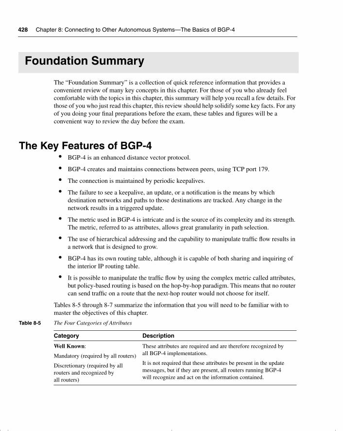
428 Chapter 8: Connecting to Other Autonomous Systems—The Basics of BGP-4
Foundation Summary
The “Foundation Summary” is a collection of quick reference information that provides a convenient review of many key concepts in this chapter. For those of you who already feel comfortable with the topics in this chapter, this summary will help you recall a few details. For those of you who just read this chapter, this review should help solidify some key facts. For any of you doing your final preparations before the exam, these tables and figures will be a convenient way to review the day before the exam.
The Key Features of BGP-4• BGP-4 is an enhanced distance vector protocol.
• BGP-4 creates and maintains connections between peers, using TCP port 179.
• The connection is maintained by periodic keepalives.
• The failure to see a keepalive, an update, or a notification is the means by which destination networks and paths to those destinations are tracked. Any change in the network results in a triggered update.
• The metric used in BGP-4 is intricate and is the source of its complexity and its strength. The metric, referred to as attributes, allows great granularity in path selection.
• The use of hierarchical addressing and the capability to manipulate traffic flow results in a network that is designed to grow.
• BGP-4 has its own routing table, although it is capable of both sharing and inquiring of the interior IP routing table.
• It is possible to manipulate the traffic flow by using the complex metric called attributes, but policy-based routing is based on the hop-by-hop paradigm. This means that no router can send traffic on a route that the next-hop router would not choose for itself.
Tables 8-5 through 8-7 summarize the information that you will need to be familiar with to master the objectives of this chapter.
Table 8-5 The Four Categories of Attributes
Category Description
Well Known:
Mandatory (required by all routers)
Discretionary (required by all routers and recognized by all routers)
These attributes are required and are therefore recognized by all BGP-4 implementations.
It is not required that these attributes be present in the update messages, but if they are present, all routers running BGP-4 will recognize and act on the information contained.
chpt_01.book Page 428 Thursday, December 21, 2000 6:22 PM
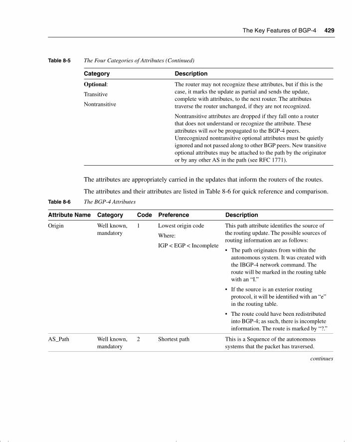
The Key Features of BGP-4 429
The attributes are appropriately carried in the updates that inform the routers of the routes.
The attributes and their attributes are listed in Table 8-6 for quick reference and comparison.
Optional:
Transitive
Nontransitive
The router may not recognize these attributes, but if this is the case, it marks the update as partial and sends the update, complete with attributes, to the next router. The attributes traverse the router unchanged, if they are not recognized.
Nontransitive attributes are dropped if they fall onto a router that does not understand or recognize the attribute. These attributes will not be propagated to the BGP-4 peers. Unrecognized nontransitive optional attributes must be quietly ignored and not passed along to other BGP peers. New transitive optional attributes may be attached to the path by the originator or by any other AS in the path (see RFC 1771).
Table 8-6 The BGP-4 Attributes
Attribute Name Category Code Preference Description
Origin Well known, mandatory
1 Lowest origin code
Where:
IGP < EGP < Incomplete
This path attribute identifies the source of the routing update. The possible sources of routing information are as follows:
• The path originates from within the autonomous system. It was created with the IBGP-4 network command. The route will be marked in the routing table with an “I.”
• If the source is an exterior routing protocol, it will be identified with an “e” in the routing table.
• The route could have been redistributed into BGP-4; as such, there is incomplete information. The route is marked by “?.”
AS_Path Well known, mandatory
2 Shortest path This is a Sequence of the autonomous systems that the packet has traversed.
continues
Table 8-5 The Four Categories of Attributes (Continued)
Category Description
chpt_01.book Page 429 Thursday, December 21, 2000 6:22 PM
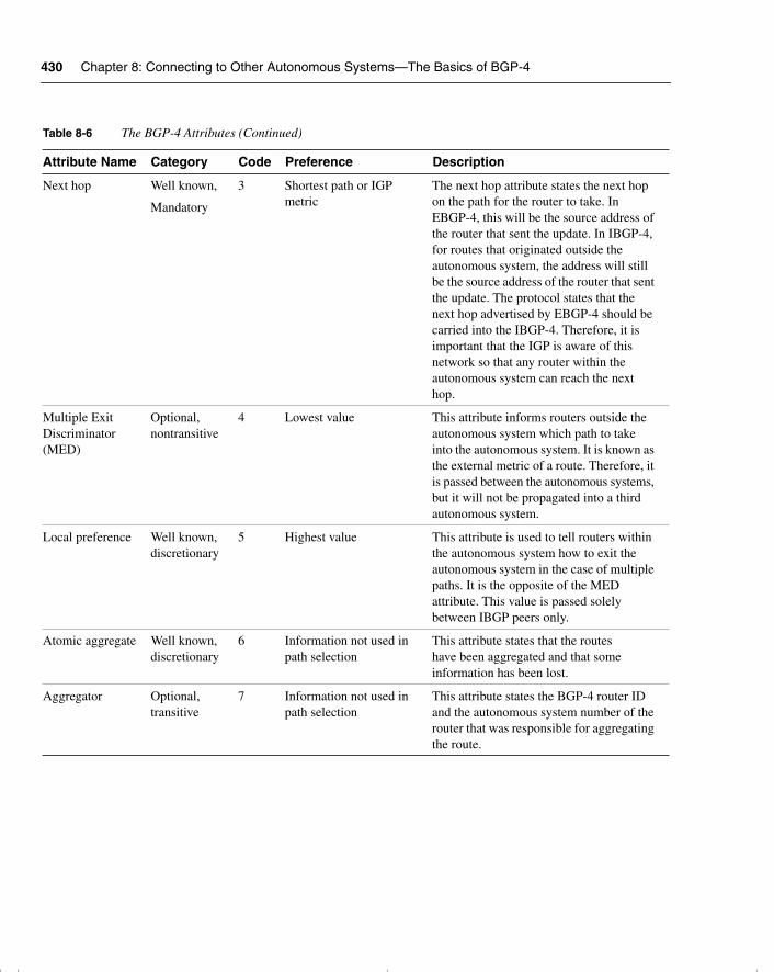
430 Chapter 8: Connecting to Other Autonomous Systems—The Basics of BGP-4
Next hop Well known,
Mandatory
3 Shortest path or IGP metric
The next hop attribute states the next hop on the path for the router to take. In EBGP-4, this will be the source address of the router that sent the update. In IBGP-4, for routes that originated outside the autonomous system, the address will still be the source address of the router that sent the update. The protocol states that the next hop advertised by EBGP-4 should be carried into the IBGP-4. Therefore, it is important that the IGP is aware of this network so that any router within the autonomous system can reach the next hop.
Multiple Exit Discriminator (MED)
Optional, nontransitive
4 Lowest value This attribute informs routers outside the autonomous system which path to take into the autonomous system. It is known as the external metric of a route. Therefore, it is passed between the autonomous systems, but it will not be propagated into a third autonomous system.
Local preference Well known, discretionary
5 Highest value This attribute is used to tell routers within the autonomous system how to exit the autonomous system in the case of multiple paths. It is the opposite of the MED attribute. This value is passed solely between IBGP peers only.
Atomic aggregate Well known, discretionary
6 Information not used in path selection
This attribute states that the routes have been aggregated and that some information has been lost.
Aggregator Optional, transitive
7 Information not used in path selection
This attribute states the BGP-4 router ID and the autonomous system number of the router that was responsible for aggregating the route.
Table 8-6 The BGP-4 Attributes (Continued)
Attribute Name Category Code Preference Description
chpt_01.book Page 430 Thursday, December 21, 2000 6:22 PM
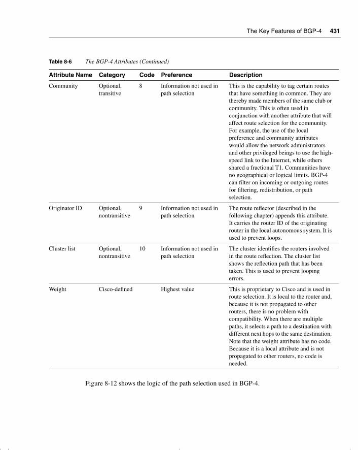
The Key Features of BGP-4 431
Figure 8-12 shows the logic of the path selection used in BGP-4.
Community Optional, transitive
8 Information not used in path selection
This is the capability to tag certain routes that have something in common. They are thereby made members of the same club or community. This is often used in conjunction with another attribute that will affect route selection for the community. For example, the use of the local preference and community attributes would allow the network administrators and other privileged beings to use the high-speed link to the Internet, while others shared a fractional T1. Communities have no geographical or logical limits. BGP-4 can filter on incoming or outgoing routes for filtering, redistribution, or path selection.
Originator ID Optional, nontransitive
9 Information not used in path selection
The route reflector (described in the following chapter) appends this attribute. It carries the router ID of the originating router in the local autonomous system. It is used to prevent loops.
Cluster list Optional, nontransitive
10 Information not used in path selection
The cluster identifies the routers involved in the route reflection. The cluster list shows the reflection path that has been taken. This is used to prevent looping errors.
Weight Cisco-defined Highest value This is proprietary to Cisco and is used in route selection. It is local to the router and, because it is not propagated to other routers, there is no problem with compatibility. When there are multiple paths, it selects a path to a destination with different next hops to the same destination. Note that the weight attribute has no code. Because it is a local attribute and is not propagated to other routers, no code is needed.
Table 8-6 The BGP-4 Attributes (Continued)
Attribute Name Category Code Preference Description
chpt_01.book Page 431 Thursday, December 21, 2000 6:22 PM
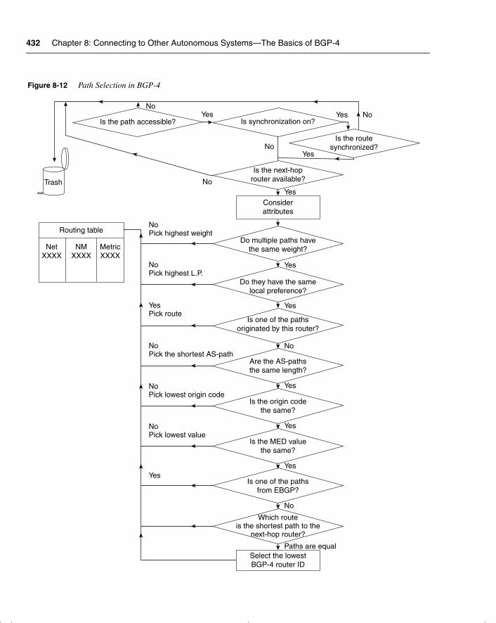
432 Chapter 8: Connecting to Other Autonomous Systems—The Basics of BGP-4
Figure 8-12 Path Selection in BGP-4
Trash
Routing table
NetXXXX
NMXXXX
MetricXXXX
Do multiple paths havethe same weight?
Is the path accessible?Yes
Is synchronization on?Yes No
NoIs the route
synchronized?
Is the next-hoprouter available?
Yes
No
No
Considerattributes
Do they have the samelocal preference?
Is one of the pathsoriginated by this router?
Are the AS-pathsthe same length?
Is the origin codethe same?
Is the MED valuethe same?
Is one of the pathsfrom EBGP?
Which routeis the shortest path to the
next-hop router?
Select the lowestBGP-4 router ID
Paths are equal
No
Yes
Yes
Yes
No
Yes
NoPick lowest value
NoPick lowest origin code
NoPick the shortest AS-path
YesPick route
NoPick highest L.P.
NoPick highest weight
Yes
Yes
Yes
chpt_01.book Page 432 Thursday, December 21, 2000 6:22 PM
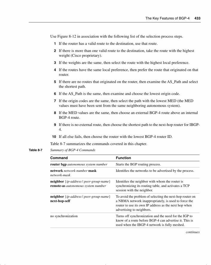
The Key Features of BGP-4 433
Use Figure 8-12 in association with the following list of the selection process steps.
1 If the router has a valid route to the destination, use that route.
2 If there is more than one valid route to the destination, take the route with the highest weight (Cisco proprietary).
3 If the weights are the same, then select the route with the highest local preference.
4 If the routes have the same local preference, then prefer the route that originated on that router.
5 If there are no routes that originated on the router, then examine the AS_Path and select the shortest path.
6 If the AS_Path is the same, then examine and choose the lowest origin code.
7 If the origin codes are the same, then select the path with the lowest MED (the MED values must have been sent from the same neighboring autonomous system).
8 If the MED values are the same, then choose an external BGP-4 route above an internal BGP-4 route.
9 If there is no external route, then choose the shortest path to the next-hop router for IBGP-4.
10 If all else fails, then choose the router with the lowest BGP-4 router ID.
Table 8-7 summarizes the commands covered in this chapter.
Table 8-7 Summary of BGP-4 Commands
Command Function
router bgp autonomous system number Starts the BGP routing process.
network network-number mask network-mask
Identifies the networks to be advertised by the process.
neighbor {ip-address | peer-group-name} remote-as autonomous system number
Identifies the neighbor with whom the router is synchronizing its routing table, and activates a TCP session with the neighbor.
neighbor {ip-address | peer-group-name} next-hop-self
To avoid the problem of selecting the next-hop router on a NBMA network inappropriately, is used to force the router to use its own IP address as the next hop when advertising to neighbors.
no synchronization Turns off synchronization and the need for the IGP to know of a route before BGP-4 can advertise it. This is used when the IBGP-4 network is fully meshed.
continues
chpt_01.book Page 433 Thursday, December 21, 2000 6:22 PM
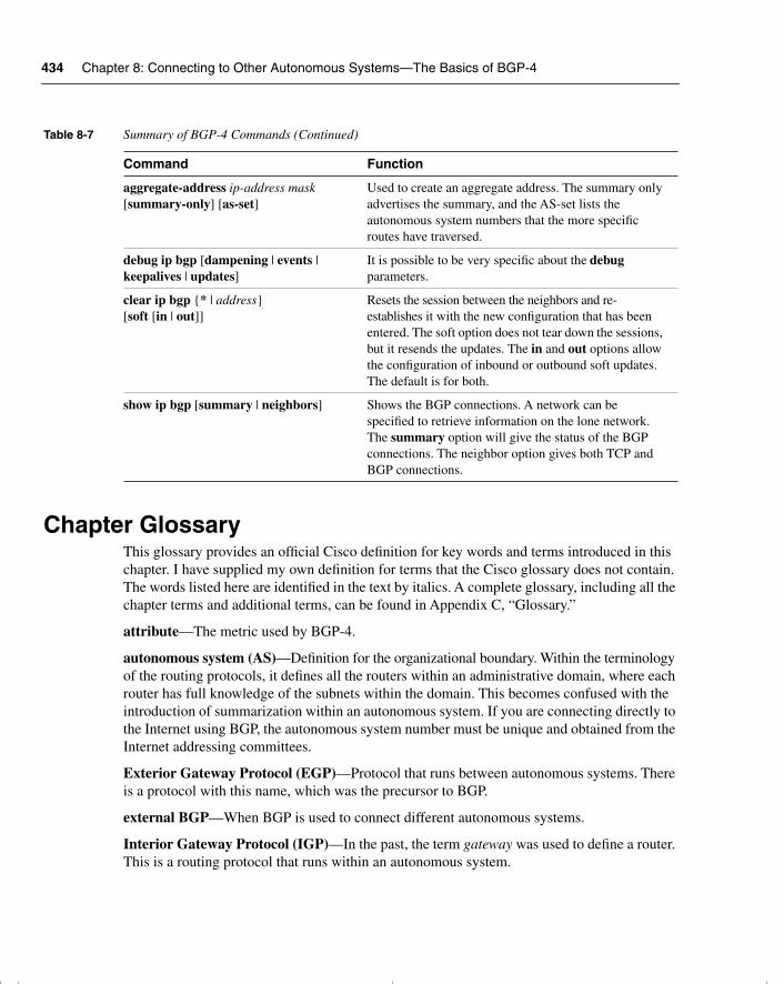
434 Chapter 8: Connecting to Other Autonomous Systems—The Basics of BGP-4
Chapter GlossaryThis glossary provides an official Cisco definition for key words and terms introduced in this chapter. I have supplied my own definition for terms that the Cisco glossary does not contain. The words listed here are identified in the text by italics. A complete glossary, including all the chapter terms and additional terms, can be found in Appendix C, “Glossary.”
attribute—The metric used by BGP-4.
autonomous system (AS)—Definition for the organizational boundary. Within the terminology of the routing protocols, it defines all the routers within an administrative domain, where each router has full knowledge of the subnets within the domain. This becomes confused with the introduction of summarization within an autonomous system. If you are connecting directly to the Internet using BGP, the autonomous system number must be unique and obtained from the Internet addressing committees.
Exterior Gateway Protocol (EGP)—Protocol that runs between autonomous systems. There is a protocol with this name, which was the precursor to BGP.
external BGP—When BGP is used to connect different autonomous systems.
Interior Gateway Protocol (IGP)—In the past, the term gateway was used to define a router. This is a routing protocol that runs within an autonomous system.
aggregate-address ip-address mask [summary-only] [as-set]
Used to create an aggregate address. The summary only advertises the summary, and the AS-set lists the autonomous system numbers that the more specific routes have traversed.
debug ip bgp [dampening | events | keepalives | updates]
It is possible to be very specific about the debug parameters.
clear ip bgp {* | address} [soft [in | out]]
Resets the session between the neighbors and re-establishes it with the new configuration that has been entered. The soft option does not tear down the sessions, but it resends the updates. The in and out options allow the configuration of inbound or outbound soft updates. The default is for both.
show ip bgp [summary | neighbors] Shows the BGP connections. A network can be specified to retrieve information on the lone network. The summary option will give the status of the BGP connections. The neighbor option gives both TCP and BGP connections.
Table 8-7 Summary of BGP-4 Commands (Continued)
Command Function
chpt_01.book Page 434 Thursday, December 21, 2000 6:22 PM

Chapter Glossary 435
internal BGP—When BGP is used to connect routers resident in the same autonomous system.
transit autonomous system—An autonomous system that is used to carry BGP-4 traffic across it to another autonomous system. None of the traffic is destined for any router within the autonomous system; it is simply being routed through it.
chpt_01.book Page 435 Thursday, December 21, 2000 6:22 PM
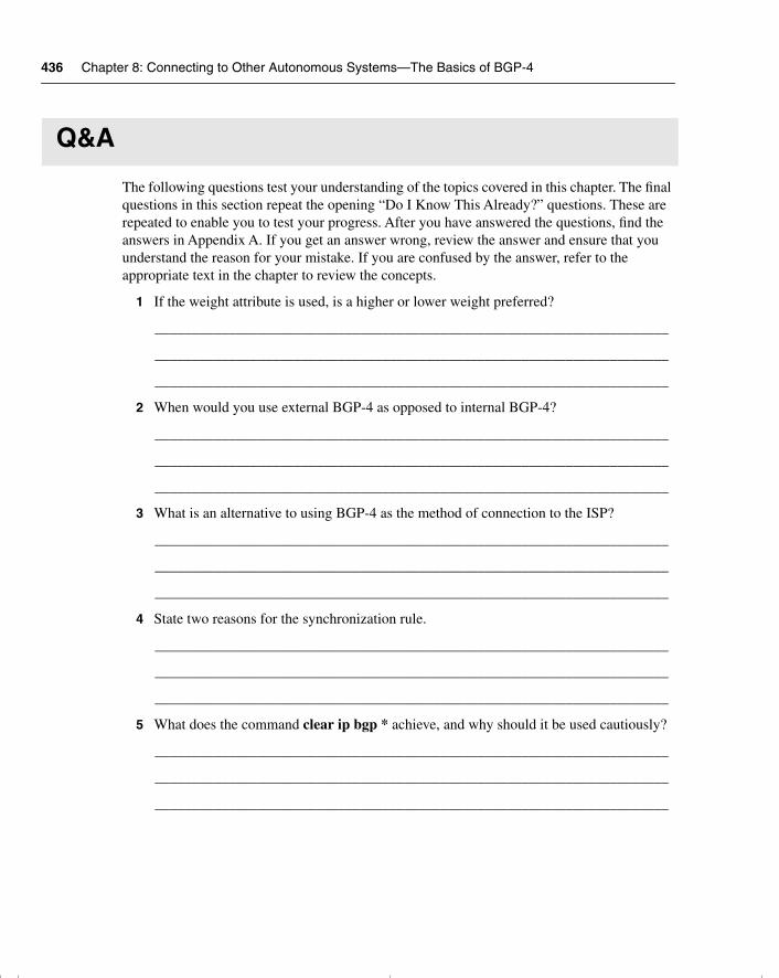
436 Chapter 8: Connecting to Other Autonomous Systems—The Basics of BGP-4
Q&A
The following questions test your understanding of the topics covered in this chapter. The final questions in this section repeat the opening “Do I Know This Already?” questions. These are repeated to enable you to test your progress. After you have answered the questions, find the answers in Appendix A. If you get an answer wrong, review the answer and ensure that you understand the reason for your mistake. If you are confused by the answer, refer to the appropriate text in the chapter to review the concepts.
1 If the weight attribute is used, is a higher or lower weight preferred?
______________________________________________________________________
______________________________________________________________________
______________________________________________________________________
2 When would you use external BGP-4 as opposed to internal BGP-4?
______________________________________________________________________
______________________________________________________________________
______________________________________________________________________
3 What is an alternative to using BGP-4 as the method of connection to the ISP?
______________________________________________________________________
______________________________________________________________________
______________________________________________________________________
4 State two reasons for the synchronization rule.
______________________________________________________________________
______________________________________________________________________
______________________________________________________________________
5 What does the command clear ip bgp * achieve, and why should it be used cautiously?
______________________________________________________________________
______________________________________________________________________
______________________________________________________________________
chpt_01.book Page 436 Thursday, December 21, 2000 6:22 PM
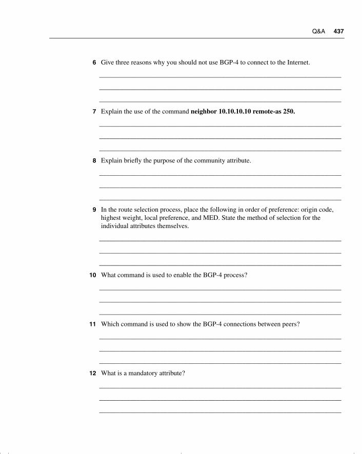
Q&A 437
6 Give three reasons why you should not use BGP-4 to connect to the Internet.
_______________________________________________________________________
_______________________________________________________________________
_______________________________________________________________________
7 Explain the use of the command neighbor 10.10.10.10 remote-as 250.
_______________________________________________________________________
_______________________________________________________________________
_______________________________________________________________________
8 Explain briefly the purpose of the community attribute.
_______________________________________________________________________
_______________________________________________________________________
_______________________________________________________________________
9 In the route selection process, place the following in order of preference: origin code, highest weight, local preference, and MED. State the method of selection for the individual attributes themselves.
_______________________________________________________________________
_______________________________________________________________________
_______________________________________________________________________
10 What command is used to enable the BGP-4 process?
_______________________________________________________________________
_______________________________________________________________________
_______________________________________________________________________
11 Which command is used to show the BGP-4 connections between peers?
_______________________________________________________________________
_______________________________________________________________________
_______________________________________________________________________
12 What is a mandatory attribute?
_______________________________________________________________________
_______________________________________________________________________
_______________________________________________________________________
chpt_01.book Page 437 Thursday, December 21, 2000 6:22 PM
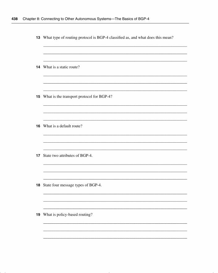
438 Chapter 8: Connecting to Other Autonomous Systems—The Basics of BGP-4
13 What type of routing protocol is BGP-4 classified as, and what does this mean?
______________________________________________________________________
______________________________________________________________________
______________________________________________________________________
14 What is a static route?
______________________________________________________________________
______________________________________________________________________
______________________________________________________________________
15 What is the transport protocol for BGP-4?
______________________________________________________________________
______________________________________________________________________
______________________________________________________________________
16 What is a default route?
______________________________________________________________________
______________________________________________________________________
______________________________________________________________________
17 State two attributes of BGP-4.
______________________________________________________________________
______________________________________________________________________
______________________________________________________________________
18 State four message types of BGP-4.
______________________________________________________________________
______________________________________________________________________
______________________________________________________________________
19 What is policy-based routing?
______________________________________________________________________
______________________________________________________________________
______________________________________________________________________
chpt_01.book Page 438 Thursday, December 21, 2000 6:22 PM
Q&A 439
20 What do the letters MED represent? Give a brief explanation of what this does.
_______________________________________________________________________
_______________________________________________________________________
_______________________________________________________________________
21 What is a community in BGP-4?
_______________________________________________________________________
_______________________________________________________________________
_______________________________________________________________________
22 Give two reasons why peer groups are useful.
_______________________________________________________________________
_______________________________________________________________________
_______________________________________________________________________
23 Explain the term “third-party next hop.”
_______________________________________________________________________
_______________________________________________________________________
_______________________________________________________________________
24 What is the difference between a peer and a neighbor?
_______________________________________________________________________
_______________________________________________________________________
_______________________________________________________________________
25 Explain briefly the synchronization rule.
_______________________________________________________________________
_______________________________________________________________________
_______________________________________________________________________
26 In BGP-4, describe the purpose of the network command.
_______________________________________________________________________
_______________________________________________________________________
_______________________________________________________________________
chpt_01.book Page 439 Thursday, December 21, 2000 6:22 PM
440 Chapter 8: Connecting to Other Autonomous Systems—The Basics of BGP-4
27 Explain the command neighbor {ip-address | peer-group-name} next-hop-self.
______________________________________________________________________
______________________________________________________________________
______________________________________________________________________
28 Which command is used to show all BGP-4 connections?
______________________________________________________________________
______________________________________________________________________
______________________________________________________________________
chpt_01.book Page 440 Thursday, December 21, 2000 6:22 PM
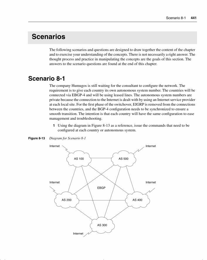
Scenario 8-1 441
Scenarios
The following scenarios and questions are designed to draw together the content of the chapter and to exercise your understanding of the concepts. There is not necessarily a right answer. The thought process and practice in manipulating the concepts are the goals of this section. The answers to the scenario questions are found at the end of this chapter.
Scenario 8-1The company Humugos is still waiting for the consultant to configure the network. The requirement is to give each country its own autonomous system number. The countries will be connected via EBGP-4 and will be using leased lines. The autonomous system numbers are private because the connection to the Internet is dealt with by using an Internet service provider at each local site. For the first phase of the switchover, EIGRP is removed from the connections between the countries, and the BGP-4 configuration needs to be synchronized to ensure a smooth transition. The intention is that each country will have the same configuration to ease management and troubleshooting.
1 Using the diagram in Figure 8-13 as a reference, issue the commands that need to be configured at each country or autonomous system.
Figure 8-13 Diagram for Scenario 8-1
AS 100 AS 500
Internet
AS 200 AS 400
AS 300
EBGP
Internet
Internet
Internet
Internet
chpt_01.book Page 441 Thursday, December 21, 2000 6:22 PM
442 Chapter 8: Connecting to Other Autonomous Systems—The Basics of BGP-4
NOTE Figure 8-13 has been simplified and does not contain the 250 autonomous systems as the case study suggests.
2 The BGP-4 network is a full-mesh network. Are there going to be any scaling problems ensuing from this?
3 What commands would indicate that there was a problem of scaling?
Scenario 8-2A small company called Insolvent, Inc., has a main office in Chicago and satellite offices on the West Coast of the United States. The company has recently changed its routing protocol to OSPF.
Insolvent has a connection to the Internet from each site, over which it does all its business. The link is a fractional T1 at the satellite offices and a full T1 at the main office. The network administrator at the main office is responsible for the corporate network and is currently trying to recruit staff to manage the local networks. He was advised at a technical seminar that BGP-4 is what he needs to connect to the Internet. Figure 8-14 shows the network.
1 Given the description of the company, and with reference to Figure 8-14, do you agree that BGP-4 is a requirement for this network? Give reasons for your answer.
2 What alternatives are available?
3 Give the alternative configuration commands for the satellite site to connect to Internet.
4 What commands would show that the link is up and operational?
chpt_01.book Page 442 Thursday, December 21, 2000 6:22 PM
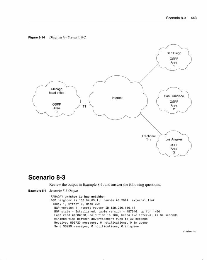
Scenario 8-3 443
Figure 8-14 Diagram for Scenario 8-2
Scenario 8-3Review the output in Example 8-1, and answer the following questions.
Example 8-1 Scenario 8-3 Output
FARADAY-gw#show ip bgp neighborBGP neighbor is 155.94.83.1, remote AS 2914, external link Index 1, Offset 0, Mask 0x2 BGP version 4, remote router ID 129.250.116.16 BGP state = Established, table version = 457046, up for 1w5d Last read 00:00:20, hold time is 180, keepalive interval is 60 seconds Minimum time between advertisement runs is 30 seconds Received 890723 messages, 0 notifications, 0 in queue Sent 36999 messages, 0 notifications, 0 in queue
continues
Chicagohead office
OSPFArea
0
San Francisco
OSPFArea
2
San Diego
OSPFArea
1
Los Angeles
OSPFArea
3
Internet
T1
FractionalT1s
chpt_01.book Page 443 Thursday, December 21, 2000 6:22 PM
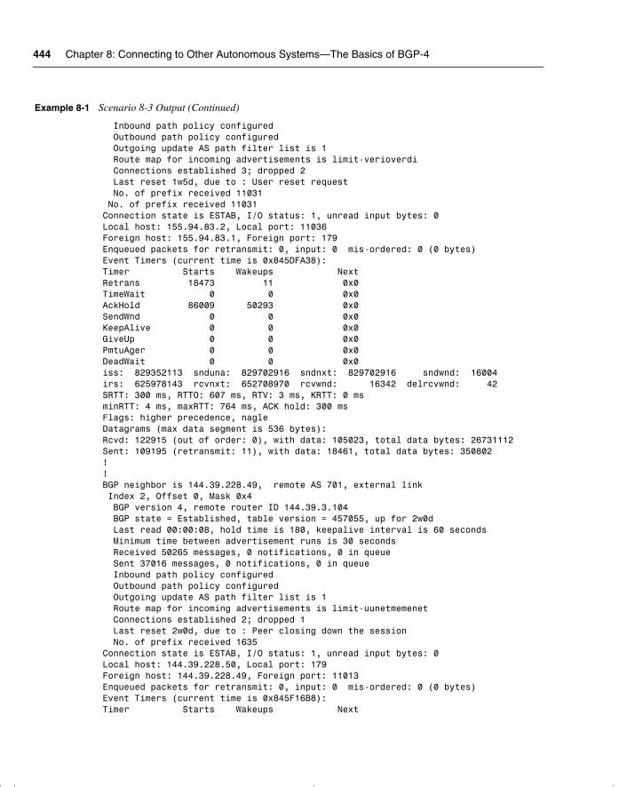
444 Chapter 8: Connecting to Other Autonomous Systems—The Basics of BGP-4
Inbound path policy configured Outbound path policy configured Outgoing update AS path filter list is 1 Route map for incoming advertisements is limit-verioverdi Connections established 3; dropped 2 Last reset 1w5d, due to : User reset request No. of prefix received 11031 No. of prefix received 11031Connection state is ESTAB, I/O status: 1, unread input bytes: 0Local host: 155.94.83.2, Local port: 11036Foreign host: 155.94.83.1, Foreign port: 179Enqueued packets for retransmit: 0, input: 0 mis-ordered: 0 (0 bytes)Event Timers (current time is 0x845DFA38):Timer Starts Wakeups NextRetrans 18473 11 0x0TimeWait 0 0 0x0AckHold 86009 50293 0x0SendWnd 0 0 0x0KeepAlive 0 0 0x0GiveUp 0 0 0x0PmtuAger 0 0 0x0DeadWait 0 0 0x0iss: 829352113 snduna: 829702916 sndnxt: 829702916 sndwnd: 16004irs: 625978143 rcvnxt: 652708970 rcvwnd: 16342 delrcvwnd: 42SRTT: 300 ms, RTTO: 607 ms, RTV: 3 ms, KRTT: 0 msminRTT: 4 ms, maxRTT: 764 ms, ACK hold: 300 msFlags: higher precedence, nagle Datagrams (max data segment is 536 bytes):Rcvd: 122915 (out of order: 0), with data: 105023, total data bytes: 26731112Sent: 109195 (retransmit: 11), with data: 18461, total data bytes: 350802!!BGP neighbor is 144.39.228.49, remote AS 701, external link Index 2, Offset 0, Mask 0x4 BGP version 4, remote router ID 144.39.3.104 BGP state = Established, table version = 457055, up for 2w0d Last read 00:00:08, hold time is 180, keepalive interval is 60 seconds Minimum time between advertisement runs is 30 seconds Received 50265 messages, 0 notifications, 0 in queue Sent 37016 messages, 0 notifications, 0 in queue Inbound path policy configured Outbound path policy configured Outgoing update AS path filter list is 1 Route map for incoming advertisements is limit-uunetmemenet Connections established 2; dropped 1 Last reset 2w0d, due to : Peer closing down the session No. of prefix received 1635Connection state is ESTAB, I/O status: 1, unread input bytes: 0Local host: 144.39.228.50, Local port: 179Foreign host: 144.39.228.49, Foreign port: 11013Enqueued packets for retransmit: 0, input: 0 mis-ordered: 0 (0 bytes)Event Timers (current time is 0x845F16B8):Timer Starts Wakeups Next
Example 8-1 Scenario 8-3 Output (Continued)
chpt_01.book Page 444 Thursday, December 21, 2000 6:22 PM
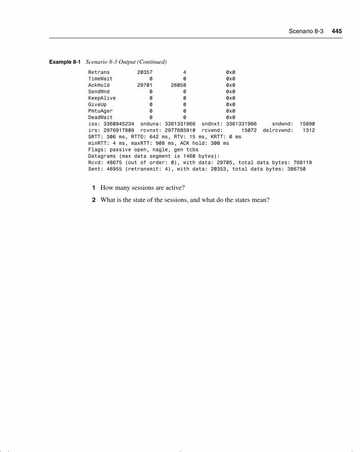
Scenario 8-3 445
1 How many sessions are active?
2 What is the state of the sessions, and what do the states mean?
Retrans 20357 4 0x0TimeWait 0 0 0x0AckHold 29701 26058 0x0SendWnd 0 0 0x0KeepAlive 0 0 0x0GiveUp 0 0 0x0PmtuAger 0 0 0x0DeadWait 0 0 0x0iss: 3360945234 snduna: 3361331966 sndnxt: 3361331966 sndwnd: 15890irs: 2976917809 rcvnxt: 2977685910 rcvwnd: 15072 delrcvwnd: 1312SRTT: 306 ms, RTTO: 642 ms, RTV: 15 ms, KRTT: 0 msminRTT: 4 ms, maxRTT: 908 ms, ACK hold: 300 msFlags: passive open, nagle, gen tcbs Datagrams (max data segment is 1460 bytes):Rcvd: 48675 (out of order: 0), with data: 29705, total data bytes: 768119Sent: 46955 (retransmit: 4), with data: 20353, total data bytes: 386750
Example 8-1 Scenario 8-3 Output (Continued)
chpt_01.book Page 445 Thursday, December 21, 2000 6:22 PM
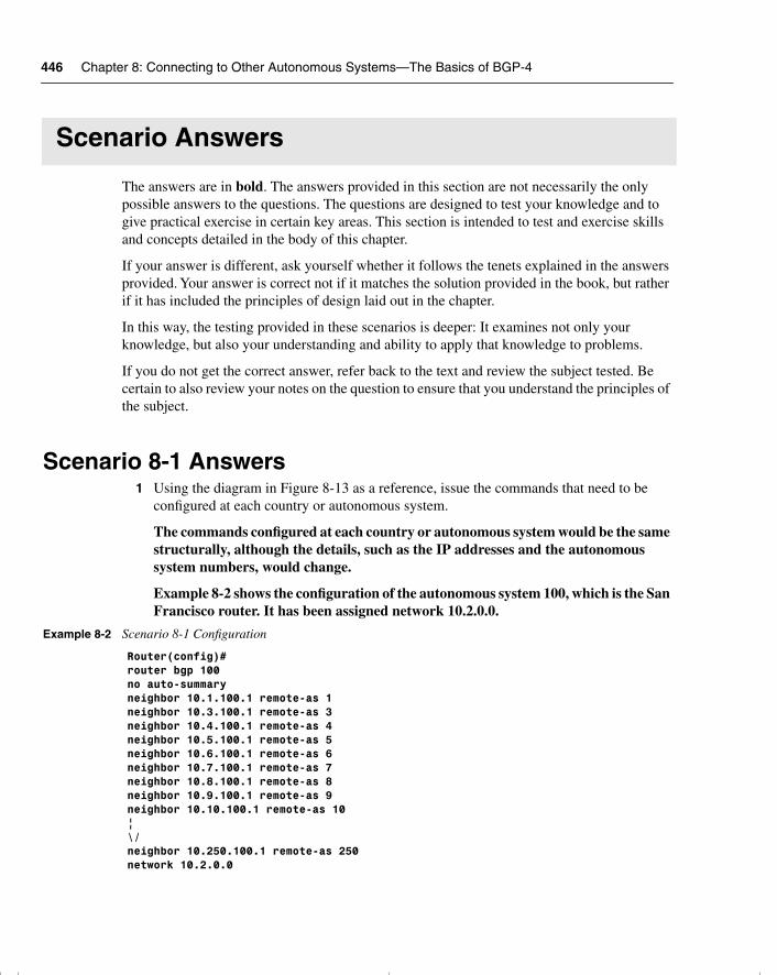
446 Chapter 8: Connecting to Other Autonomous Systems—The Basics of BGP-4
Scenario Answers
The answers are in bold. The answers provided in this section are not necessarily the only possible answers to the questions. The questions are designed to test your knowledge and to give practical exercise in certain key areas. This section is intended to test and exercise skills and concepts detailed in the body of this chapter.
If your answer is different, ask yourself whether it follows the tenets explained in the answers provided. Your answer is correct not if it matches the solution provided in the book, but rather if it has included the principles of design laid out in the chapter.
In this way, the testing provided in these scenarios is deeper: It examines not only your knowledge, but also your understanding and ability to apply that knowledge to problems.
If you do not get the correct answer, refer back to the text and review the subject tested. Be certain to also review your notes on the question to ensure that you understand the principles of the subject.
Scenario 8-1 Answers1 Using the diagram in Figure 8-13 as a reference, issue the commands that need to be
configured at each country or autonomous system.
The commands configured at each country or autonomous system would be the same structurally, although the details, such as the IP addresses and the autonomous system numbers, would change.
Example 8-2 shows the configuration of the autonomous system 100, which is the San Francisco router. It has been assigned network 10.2.0.0.
Example 8-2 Scenario 8-1 Configuration
Router(config)#router bgp 100 no auto-summaryneighbor 10.1.100.1 remote-as 1 neighbor 10.3.100.1 remote-as 3 neighbor 10.4.100.1 remote-as 4neighbor 10.5.100.1 remote-as 5 neighbor 10.6.100.1 remote-as 6 neighbor 10.7.100.1 remote-as 7neighbor 10.8.100.1 remote-as 8neighbor 10.9.100.1 remote-as 9neighbor 10.10.100.1 remote-as 10|\/neighbor 10.250.100.1 remote-as 250network 10.2.0.0
chpt_01.book Page 446 Thursday, December 21, 2000 6:22 PM
Scenario 8-2 Answers 447
The protocol has had the neighbors in each autonomous system defined with their next-hop IP address and the number of the autonomous system to which they are connecting. The no auto-summary command is used to ensure that the subnets of network 10.0.0.0 are advertised; otherwise, each subnet would need to be defined as a network command.
2 The BGP-4 network is a full-mesh network. Are there going to be any scaling problems ensuing from this?
There should not be a problem with this design because although there are an enormous number of TCP connections, the traffic is minimal, particularly if aggregation is configured. Also, BGP sends only triggered updates, so if the network is stable and route aggregation is configured, then bandwidth should not be a concern. However, considering the propagation delays, the BGP timers may need to be reviewed. Regarding CPU, a high-power router should be used for this purpose.
3 What commands would indicate that there was a problem of scaling?
The commands that should be used to determine whether there is a problem are as follows:
— show ip bgp neighbors
— show ip bgp sessions
— show ip bgp
— show processes cpu
Scenario 8-2 Answers1 Given the description of the company, and with reference to Figure 8-14, do you agree that
BGP-4 is a requirement for this network? Give reasons for your answer.
Because the company is small and has only a single connection per site into the Internet, it would be too complex to configure and maintain BGP-4 when there simply are not enough resources. The bandwidth is inadequate for the task, and the administrative expertise is already overstretched. It would be far better to configure a static/default route to the Internet and to redistribute this route into the IGP running within the autonomous system.
2 What alternatives are available?
The only real alternative is the one already mentioned, to configure a default route into the Internet from every location and to redistribute this default route into the IGP for the autonomous system.
chpt_01.book Page 447 Thursday, December 21, 2000 6:22 PM
448 Chapter 8: Connecting to Other Autonomous Systems—The Basics of BGP-4
3 Give the alternative configuration commands for the satellite site to connect to Internet.
Each site would have the same configuration structure, although the details may differ:
ip route 0.0.0.0 0.0.0.0 router ospf 100network 207.111.9.0 0.0.0.255 area 0default-information originate always
The first line configures the default route.
The second line turns on the OSPF process 100.
The third line identifies which interfaces are participating in OSPF and what area they are in.
The fourth line propagates the default route into the network, whether or not the advertising router has a path to the network.
4 What commands would show that the link is up and operational?
The commands to prove that the link is up and operational would be the show ip route command as well as the ping and traceroute commands. Refer to CCO or the ICND course or coursebook for more details on these commands.
Scenario 8-3 Answers1 How many sessions are active?
There are two active sessions. In reading the large amount of information on the show ip bgp neighbor command, there is a line at the beginning of each session identifying the neighboring peer. The lines in this output screen are as follows:
BGP neighbor is 155.94.83.1, remote AS 2914, external linkBGP neighbor is 144.39.228.49, remote AS 701, external link
2 What is the state of the sessions, and what do the states mean?
BGP state = Established, table version = 457046, up for 1w5dBGP state = Established, table version = 457055, up for 2w0d
Both the peers have established sessions. This means that they have a TCP session. They are now in a position to exchange routing tables and to synchronize their databases. The rest of the line indicates how many times the table has been updated and how long the session has been maintained. In this example, the first peer has had a session with the local router for one week and five days, while the second peer has been up for exactly two weeks. How many autonomous systems are there?
chpt_01.book Page 448 Thursday, December 21, 2000 6:22 PM
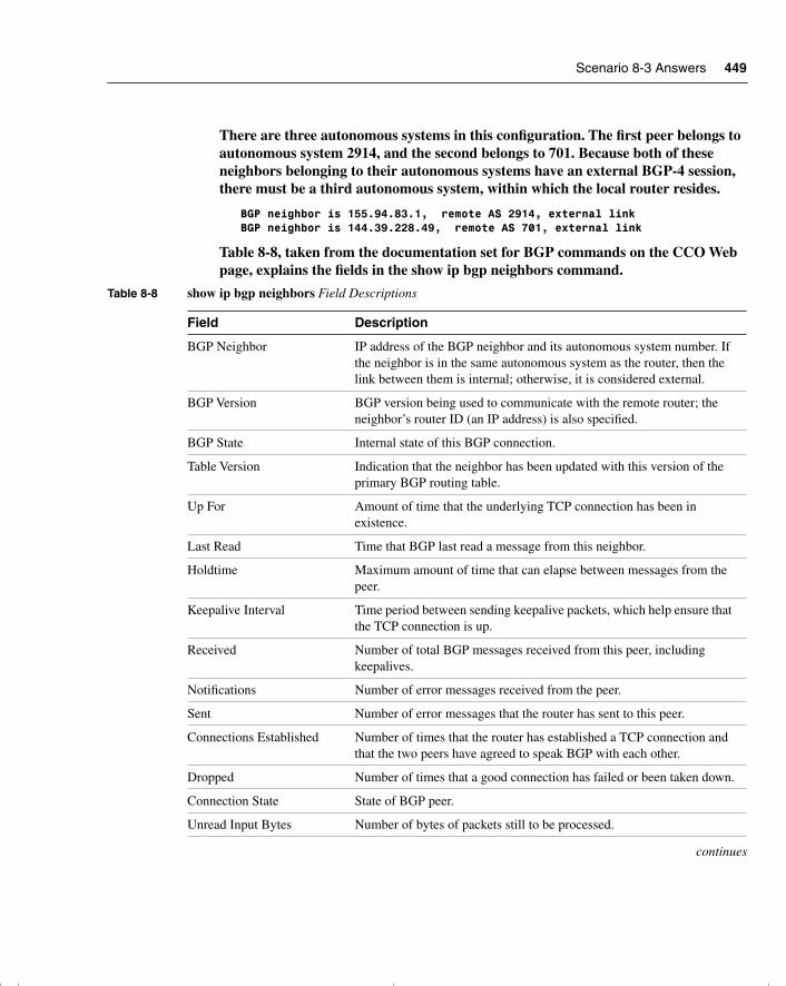
Scenario 8-3 Answers 449
There are three autonomous systems in this configuration. The first peer belongs to autonomous system 2914, and the second belongs to 701. Because both of these neighbors belonging to their autonomous systems have an external BGP-4 session, there must be a third autonomous system, within which the local router resides.
BGP neighbor is 155.94.83.1, remote AS 2914, external linkBGP neighbor is 144.39.228.49, remote AS 701, external link
Table 8-8, taken from the documentation set for BGP commands on the CCO Web page, explains the fields in the show ip bgp neighbors command.
Table 8-8 show ip bgp neighbors Field Descriptions
Field Description
BGP Neighbor IP address of the BGP neighbor and its autonomous system number. If the neighbor is in the same autonomous system as the router, then the link between them is internal; otherwise, it is considered external.
BGP Version BGP version being used to communicate with the remote router; the neighbor’s router ID (an IP address) is also specified.
BGP State Internal state of this BGP connection.
Table Version Indication that the neighbor has been updated with this version of the primary BGP routing table.
Up For Amount of time that the underlying TCP connection has been in existence.
Last Read Time that BGP last read a message from this neighbor.
Holdtime Maximum amount of time that can elapse between messages from the peer.
Keepalive Interval Time period between sending keepalive packets, which help ensure that the TCP connection is up.
Received Number of total BGP messages received from this peer, including keepalives.
Notifications Number of error messages received from the peer.
Sent Number of error messages that the router has sent to this peer.
Connections Established Number of times that the router has established a TCP connection and that the two peers have agreed to speak BGP with each other.
Dropped Number of times that a good connection has failed or been taken down.
Connection State State of BGP peer.
Unread Input Bytes Number of bytes of packets still to be processed.
continues
chpt_01.book Page 449 Thursday, December 21, 2000 6:22 PM
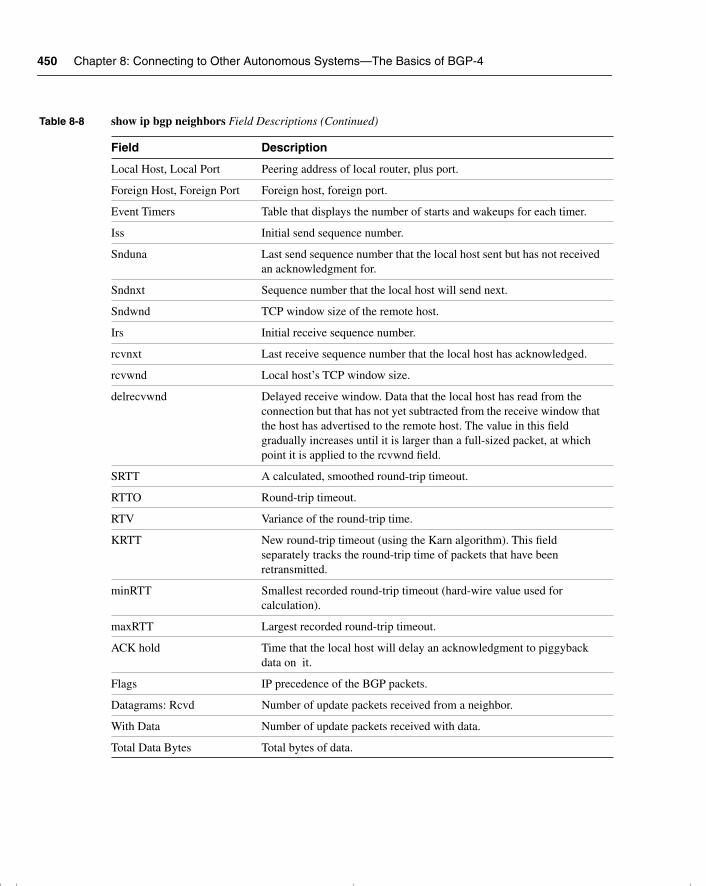
450 Chapter 8: Connecting to Other Autonomous Systems—The Basics of BGP-4
Local Host, Local Port Peering address of local router, plus port.
Foreign Host, Foreign Port Foreign host, foreign port.
Event Timers Table that displays the number of starts and wakeups for each timer.
Iss Initial send sequence number.
Snduna Last send sequence number that the local host sent but has not received an acknowledgment for.
Sndnxt Sequence number that the local host will send next.
Sndwnd TCP window size of the remote host.
Irs Initial receive sequence number.
rcvnxt Last receive sequence number that the local host has acknowledged.
rcvwnd Local host’s TCP window size.
delrecvwnd Delayed receive window. Data that the local host has read from the connection but that has not yet subtracted from the receive window that the host has advertised to the remote host. The value in this field gradually increases until it is larger than a full-sized packet, at which point it is applied to the rcvwnd field.
SRTT A calculated, smoothed round-trip timeout.
RTTO Round-trip timeout.
RTV Variance of the round-trip time.
KRTT New round-trip timeout (using the Karn algorithm). This field separately tracks the round-trip time of packets that have been retransmitted.
minRTT Smallest recorded round-trip timeout (hard-wire value used for calculation).
maxRTT Largest recorded round-trip timeout.
ACK hold Time that the local host will delay an acknowledgment to piggyback data on it.
Flags IP precedence of the BGP packets.
Datagrams: Rcvd Number of update packets received from a neighbor.
With Data Number of update packets received with data.
Total Data Bytes Total bytes of data.
Table 8-8 show ip bgp neighbors Field Descriptions (Continued)
Field Description
chpt_01.book Page 450 Thursday, December 21, 2000 6:22 PM
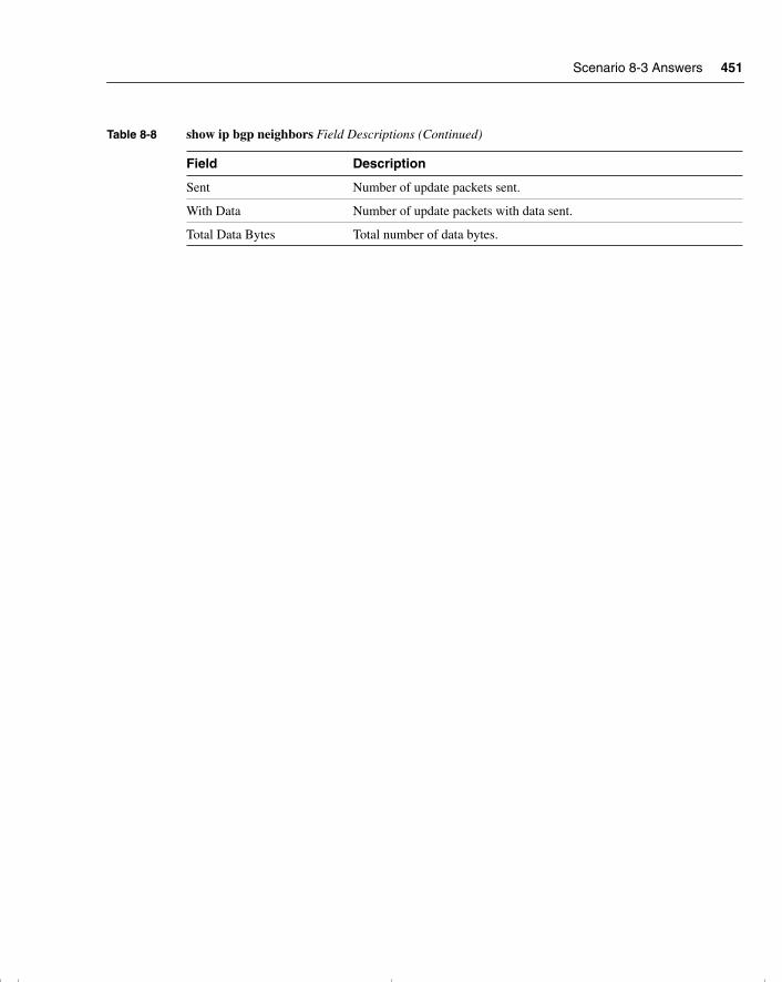
Scenario 8-3 Answers 451
Sent Number of update packets sent.
With Data Number of update packets with data sent.
Total Data Bytes Total number of data bytes.
Table 8-8 show ip bgp neighbors Field Descriptions (Continued)
Field Description
chpt_01.book Page 451 Thursday, December 21, 2000 6:22 PM

This chapter covers the following topics that you will need to master to pass the CCNP/CCDP Routing exam:
• The scalability problems inherent in BGP-4.
• The concept and configuration of route reflectors.
• The concept and configuration of policy control using prefix lists.
• Methods of connecting to multiple autonomous systems.
• Redistribution between IGPs and EBGP.
• The Cisco commands for tuning BGP-4 and the Cisco commands for reviewing the configuration.
chpt_01.book Page 452 Thursday, December 21, 2000 6:22 PM
C H A P T E R 9
Implementing and Tuning BGP for Use in Large Networks
The topics in this chapter concern the advanced configuration of BGP-4. You will need to apply your understanding of the basic concepts and configuration of BGP-4 that you gained in the last chapter because, in this chapter, the full complexity and sophistication of BGP-4 is explained. In this chapter, the true use of BGP-4 is explored—whether its use is to connect to an ISP or even to act as an ISP with several connected organizations. The chapter covers how BGP-4 can be configured to select a particular path and the design features and pitfalls of BGP. In this discussion of the advanced configuration of BGP-4, the explanation of the technology is coupled with configuration examples so that your conceptual understanding of BGP is reinforced by concrete implementation examples.
The topics in this chapter will directly reflect questions on the Routing exam. BGP-4 is a routing protocol designed for use in large networks. As a well-known attribute to the networking world, it is a mandatory topic in the Routing exam. The BSCN course devotes 11 percent of its material to implementing BGP in scalable networks. Because nearly a quarter of the BSCN course is devoted to BGP, as reflected in Chapter 8, “Connecting to Other Autonomous Systems—The Basics of BGP-4,” and Chapter 9, “Implementing and Tuning BGP for Use in Large Networks,” you should expect quite a few BGP questions on the test to reflect this concentration.
How to Best Use This ChapterBy taking the following steps, you can make better use of your study time:
• Keep your notes and the answers for all your work with this book in one place, for easy reference.
• When you take a quiz, write down your answers. Studies show that retention significantly increases by writing down facts and concepts, even if you never look at the information again.
• Use the diagram in Figure 9-1 to guide you to the next step.
chpt_01.book Page 453 Thursday, December 21, 2000 6:22 PM
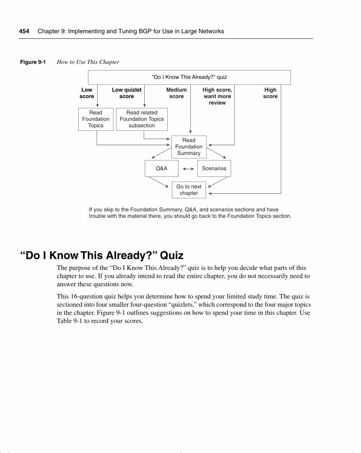
454 Chapter 9: Implementing and Tuning BGP for Use in Large Networks
Figure 9-1 How to Use This Chapter
“Do I Know This Already?” QuizThe purpose of the “Do I Know This Already?” quiz is to help you decide what parts of this chapter to use. If you already intend to read the entire chapter, you do not necessarily need to answer these questions now.
This 16-question quiz helps you determine how to spend your limited study time. The quiz is sectioned into four smaller four-question “quizlets,” which correspond to the four major topics in the chapter. Figure 9-1 outlines suggestions on how to spend your time in this chapter. Use Table 9-1 to record your scores.
Lowscore
Low quizletscore
Mediumscore
High score,want more
review
Highscore
"Do I Know This Already?" quiz
ReadFoundation
Topics
Read relatedFoundation Topics
subsection
ReadFoundationSummary
Q&A Scenarios
Go to nextchapter
If you skip to the Foundation Summary, Q&A, and scenarios sections and havetrouble with the material there, you should go back to the Foundation Topics section.
chpt_01.book Page 454 Thursday, December 21, 2000 6:22 PM
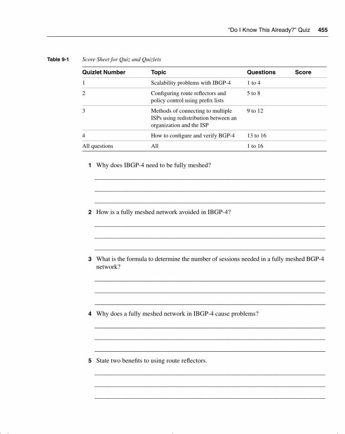
“Do I Know This Already?” Quiz 455
1 Why does IBGP-4 need to be fully meshed?
_______________________________________________________________________
_______________________________________________________________________
_______________________________________________________________________
2 How is a fully meshed network avoided in IBGP-4?
_______________________________________________________________________
_______________________________________________________________________
_______________________________________________________________________
3 What is the formula to determine the number of sessions needed in a fully meshed BGP-4 network?
_______________________________________________________________________
_______________________________________________________________________
_______________________________________________________________________
4 Why does a fully meshed network in IBGP-4 cause problems?
_______________________________________________________________________
_______________________________________________________________________
_______________________________________________________________________
5 State two benefits to using route reflectors.
_______________________________________________________________________
_______________________________________________________________________
_______________________________________________________________________
Table 9-1 Score Sheet for Quiz and Quizlets
Quizlet Number Topic Questions Score
1 Scalability problems with IBGP-4 1 to 4
2 Configuring route reflectors and policy control using prefix lists
5 to 8
3 Methods of connecting to multiple ISPs using redistribution between an organization and the ISP
9 to 12
4 How to configure and verify BGP-4 13 to 16
All questions All 1 to 16
chpt_01.book Page 455 Thursday, December 21, 2000 6:22 PM
456 Chapter 9: Implementing and Tuning BGP for Use in Large Networks
6 Can the next-hop-self option be used between EBGP-4 peers?
______________________________________________________________________
______________________________________________________________________
______________________________________________________________________
7 Explain the difference between a cluster-ID and an originator-ID.
______________________________________________________________________
______________________________________________________________________
______________________________________________________________________
8 State two advantages in using prefix lists over access lists.
______________________________________________________________________
______________________________________________________________________
______________________________________________________________________
9 If the ISP has provided a default route, how will the router within the autonomous system select the exit path in a multihomed environment?
______________________________________________________________________
______________________________________________________________________
______________________________________________________________________
10 What is a disadvantage of an autonomous system receiving full routing updates from all providers?
______________________________________________________________________
______________________________________________________________________
______________________________________________________________________
11 What is the danger of redistributing BGP-4 into the IGP?
______________________________________________________________________
______________________________________________________________________
______________________________________________________________________
12 What are the advantages of a fully meshed IBGP-4 network?
______________________________________________________________________
______________________________________________________________________
______________________________________________________________________
chpt_01.book Page 456 Thursday, December 21, 2000 6:22 PM
“Do I Know This Already?” Quiz 457
13 In configuring a route reflector, how is the client configured?
_______________________________________________________________________
_______________________________________________________________________
_______________________________________________________________________
14 What command is used to display the route reflector clients?
_______________________________________________________________________
_______________________________________________________________________
_______________________________________________________________________
15 What commands are used to display the BGP-4 router ID that identifies the router that is sending the updates and peering with its neighbor?
_______________________________________________________________________
_______________________________________________________________________
_______________________________________________________________________
16 Which command is used to display the AS_Path?
_______________________________________________________________________
_______________________________________________________________________
_______________________________________________________________________
The answers to this quiz are found in Appendix A, “Answers to Quiz Questions.” The suggested choices for your next step are as follows:
• 2 or less on any quizlet—Review the appropriate sections of the “Foundation Topics” portion of this chapter, based on Table 9-1. Then move on to the “Foundation Summary” section, the “Q&A” section, and the “Scenarios” at the end of the chapter.
• 8 or less overall score—Read the entire chapter. This includes the “Foundation Topics” and “Foundation Summary” sections, the “Q&A” section, and the “Scenarios” at the end of the chapter.
• 9 to 12 overall score—Begin with the “Foundation Summary” section, and then go to the “Q&A” section and the “Scenarios” at the end of the chapter. If you have trouble with these exercises, read the appropriate sections in “Foundation Topics.”
• 13 or more overall score—If you want more review on these topics, skip to the “Foundation Summary” section, and then go to the “Q&A” section and the “Scenarios” at the end of the chapter. Otherwise, move to the next chapter.
chpt_01.book Page 457 Thursday, December 21, 2000 6:22 PM
458 Chapter 9: Implementing and Tuning BGP for Use in Large Networks
Foundation Topics
Introduction—Communicating with Other Autonomous Systems with BGP-4
The BSCN course deals with connectivity to the Internet via a service provider. One of the methods used to make this connection is the external routing protocol BGP-4.
The Routing 2.0 exam, recognizing that BGP-4 is increasingly important in larger environments to communicate with the Internet agent or service provider, covers a conceptual overview of BGP-4. A solid understanding of BGP-4, as well as basic configuration commands, is expected on the Routing exam. However, you should know that if your network is a simple one, using static and default routes may be configurations that are more appropriate. This chapter builds on the basic BGP-4 concepts and commands that were outlined in the previous chapter and deals with the complexities of traffic management and path selection in large BGP-4 environments.
Case StudyAs seen in the last chapter, the large multinational company Humugos has offices in 250 countries. Each country operates as a separate company, conforming to the tax and legal laws of the country. It is still important that each part of the organization must be capable of connecting to the others, but EIGRP is no longer feasible for a number of reasons. The main issue is the number of connections that each country has into the Internet. There is also some need to manipulate the traffic, particularly in terms of resource sharing between business units internationally.
The network topology of the case study Humugos is illustrated in Figure 9-2.
BGP-4 has been suggested as a solution for various reasons. First, the company needs yet another level of hierarchy. Second, the multiple connections to the Internet need to be managed with a sophisticated routing protocol. The capability to determine the traffic path that will be taken by a variety of parameters is also very important. This adds another dimension to the simple metric, which proves inadequate to the task of determining subtle distinctions in path selection.
The countries have now been configured to communicate using BGP-4 as the routing protocol between each country or autonomous system. This chapter deals with the design and configuration of the company’s connections into the Internet.
chpt_01.book Page 458 Thursday, December 21, 2000 6:22 PM
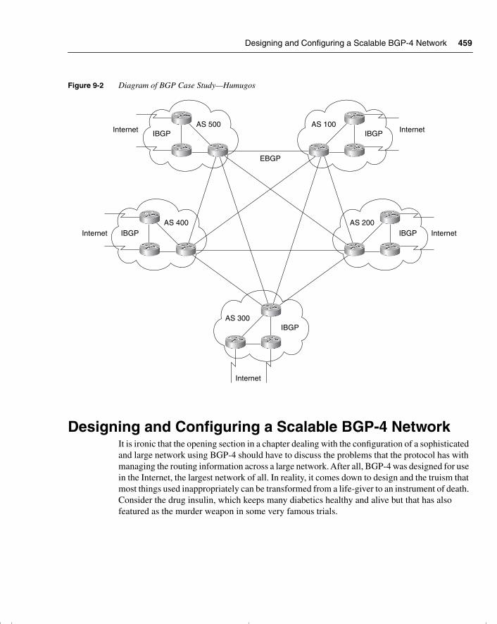
Designing and Configuring a Scalable BGP-4 Network 459
Figure 9-2 Diagram of BGP Case Study—Humugos
Designing and Configuring a Scalable BGP-4 Network It is ironic that the opening section in a chapter dealing with the configuration of a sophisticated and large network using BGP-4 should have to discuss the problems that the protocol has with managing the routing information across a large network. After all, BGP-4 was designed for use in the Internet, the largest network of all. In reality, it comes down to design and the truism that most things used inappropriately can be transformed from a life-giver to an instrument of death. Consider the drug insulin, which keeps many diabetics healthy and alive but that has also featured as the murder weapon in some very famous trials.
Internet
Internet Internet
Internet
Internet
EBGP
AS 100
AS 200
AS 300
AS 400
AS 500IBGPIBGP
IBGP IBGP
IBGP
chpt_01.book Page 459 Thursday, December 21, 2000 6:22 PM
460 Chapter 9: Implementing and Tuning BGP for Use in Large Networks
Why Does BGP-4 Require a Fully Meshed Network?The issue with BGP-4’s capability ton, scale is confined to that of Internal BGP-4, where a fully meshed configuration is required to ensure full connectivity. Remember that to avoid routing loops, the protocol must follow the rule that no updates learned from Internal peers can be sent to other internal peers. This is similar to the IGP split horizon rule. An IBGP-4 router will propagate a route under the following conditions:
• If it is a route generated by the transmitting router
• If it is a connected route
Remember, if the router was learned via an update from a BGP-4 peer within the same autonomous system, it can propagate this route only to an EBGP-4 peer. For this reason, internal BGP-4 peers must all be connected to one another (fully meshed) to have a complete knowledge of the network.
Why Is a Fully Meshed Network a Problem? The problem is that BGP-4 maintains up-to-date and accurate routing information by sending incremental updates across a TCP connection. The TCP connection is an excellent way of ensuring the accuracy of the information, but it is costly in network resources. The greater the number of connections, the greater the number of required resources. A simple equation demonstrates the problem, one that is also seen in the consideration of designing fully meshed Frame Relay networks.
The Equation for Determining the Number of IBGP-4 SessionsThe equation for determining the number of sessions required is as follows:
n (n – 1) / 2
In plain English, that is the number of routers minus 1, multiplied by the number of routers, and then divided by 2. Thus, 10 routers would mean 10 (10 – 1) / 2 = 10 × 9 / 2 = 45 sessions.
This works well in environments that require a few connections, such as a company with multiple connections into the Internet. However, if the network is an ISP that is using BGP-4 throughout its network, some careful design should be put in place.
To be fair to TCP, it is not simply the maintenance of the connection that eats up resources, but the amount of updates that traverse those links. If every router is connected to every other router, a lot of the information that is being sent is duplicated. Figure 9-3 illustrates the redundancy.
chpt_01.book Page 460 Thursday, December 21, 2000 6:22 PM
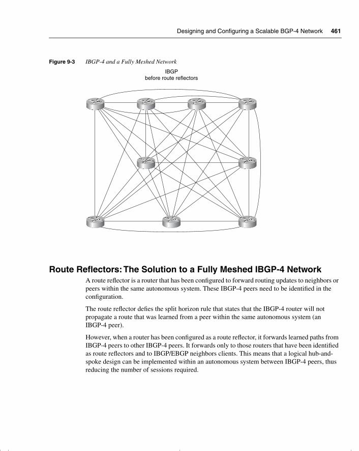
Designing and Configuring a Scalable BGP-4 Network 461
Figure 9-3 IBGP-4 and a Fully Meshed Network
Route Reflectors: The Solution to a Fully Meshed IBGP-4 NetworkA route reflector is a router that has been configured to forward routing updates to neighbors or peers within the same autonomous system. These IBGP-4 peers need to be identified in the configuration.
The route reflector defies the split horizon rule that states that the IBGP-4 router will not propagate a route that was learned from a peer within the same autonomous system (an IBGP-4 peer).
However, when a router has been configured as a route reflector, it forwards learned paths from IBGP-4 peers to other IBGP-4 peers. It forwards only to those routers that have been identified as route reflectors and to IBGP/EBGP neighbors clients. This means that a logical hub-and-spoke design can be implemented within an autonomous system between IBGP-4 peers, thus reducing the number of sessions required.
IBGPbefore route reflectors
chpt_01.book Page 461 Thursday, December 21, 2000 6:22 PM
462 Chapter 9: Implementing and Tuning BGP for Use in Large Networks
WARNING The route reflector concept means that there is more overhead on the route reflector and, if configured incorrectly, can cause serious routing loops.
Designs That Avoid a Fully Meshed IBGP-4 NetworkThe problem presented by a fully meshed IBGP-4 network can be solved by design. If a hub-and-spoke network were developed, this would streamline the TCP connections. This is a good thing, but it does require some additional design and configuration. The solution is the implementation of route reflectors and the network design that they support.
The design can become quite complicated with multiple route reflectors that afford redundancy, which is always reassuring. Multiple levels of route reflector can even be configured, creating a hierarchical design.
Nonroute reflector routers are not affected by the change in design and routing update propagation. Indeed, they are blissfully unaware of any changes because they still receive the updates that they need. The updates are also unchanged because no changes are made to the attribute values. This makes migration to a network design incorporating route reflectors very straightforward.
The only design requirement is that the IBGP-4 route reflectors must be fully meshed to ensure the correct propagation of updates. This is illustrated in Figure 9-4.
The benefits of route reflectors include these:
• The capability to scale the network, given the other characteristics
• A strong hierarchical design
• A reduction of traffic on the network
• A reduction in the memory and CPU to maintain TCP sessions on the client IBGP-4 peers
• Faster convergence because synchronization is not needed
• Faster convergence and a simpler network because two routing protocols are implemented:
— IBGP-4 for external routing information traversing the autonomous system
— IGP for routes internal to the autonomous system
The solution provided by route reflectors is used in large IBGP-4 environments such as ISP networks, where a fully meshed IBGP-4 network could result in a large number of TCP sessions.
chpt_01.book Page 462 Thursday, December 21, 2000 6:22 PM
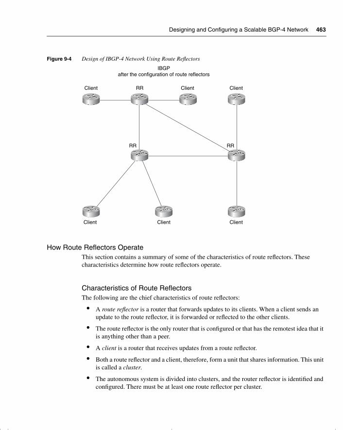
Designing and Configuring a Scalable BGP-4 Network 463
Figure 9-4 Design of IBGP-4 Network Using Route Reflectors
How Route Reflectors OperateThis section contains a summary of some of the characteristics of route reflectors. These characteristics determine how route reflectors operate.
Characteristics of Route ReflectorsThe following are the chief characteristics of route reflectors:
• A route reflector is a router that forwards updates to its clients. When a client sends an update to the route reflector, it is forwarded or reflected to the other clients.
• The route reflector is the only router that is configured or that has the remotest idea that it is anything other than a peer.
• A client is a router that receives updates from a route reflector.
• Both a route reflector and a client, therefore, form a unit that shares information. This unit is called a cluster.
• The autonomous system is divided into clusters, and the router reflector is identified and configured. There must be at least one route reflector per cluster.
IBGPafter the configuration of route reflectors
Client Client Client
ClientClientClient
RR
RR RR
chpt_01.book Page 463 Thursday, December 21, 2000 6:22 PM
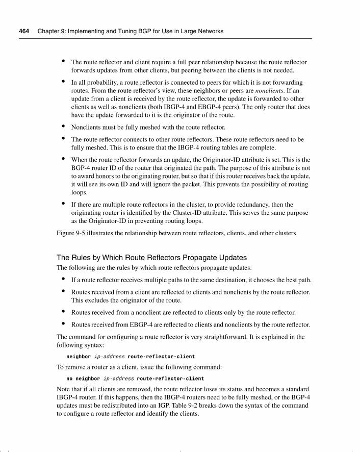
464 Chapter 9: Implementing and Tuning BGP for Use in Large Networks
• The route reflector and client require a full peer relationship because the route reflector forwards updates from other clients, but peering between the clients is not needed.
• In all probability, a route reflector is connected to peers for which it is not forwarding routes. From the route reflector’s view, these neighbors or peers are nonclients. If an update from a client is received by the route reflector, the update is forwarded to other clients as well as nonclients (both IBGP-4 and EBGP-4 peers). The only router that does have the update forwarded to it is the originator of the route.
• Nonclients must be fully meshed with the route reflector.
• The route reflector connects to other route reflectors. These route reflectors need to be fully meshed. This is to ensure that the IBGP-4 routing tables are complete.
• When the route reflector forwards an update, the Originator-ID attribute is set. This is the BGP-4 router ID of the router that originated the path. The purpose of this attribute is not to award honors to the originating router, but so that if this router receives back the update, it will see its own ID and will ignore the packet. This prevents the possibility of routing loops.
• If there are multiple route reflectors in the cluster, to provide redundancy, then the originating router is identified by the Cluster-ID attribute. This serves the same purpose as the Originator-ID in preventing routing loops.
Figure 9-5 illustrates the relationship between route reflectors, clients, and other clusters.
The Rules by Which Route Reflectors Propagate UpdatesThe following are the rules by which route reflectors propagate updates:
• If a route reflector receives multiple paths to the same destination, it chooses the best path.
• Routes received from a client are reflected to clients and nonclients by the route reflector. This excludes the originator of the route.
• Routes received from a nonclient are reflected to clients only by the route reflector.
• Routes received from EBGP-4 are reflected to clients and nonclients by the route reflector.
The command for configuring a route reflector is very straightforward. It is explained in the following syntax:
neighbor ip-address route-reflector-client
To remove a router as a client, issue the following command:
no neighbor ip-address route-reflector-client
Note that if all clients are removed, the route reflector loses its status and becomes a standard IBGP-4 router. If this happens, then the IBGP-4 routers need to be fully meshed, or the BGP-4 updates must be redistributed into an IGP. Table 9-2 breaks down the syntax of the command to configure a route reflector and identify the clients.
chpt_01.book Page 464 Thursday, December 21, 2000 6:22 PM
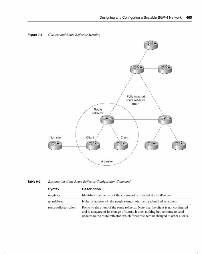
Designing and Configuring a Scalable BGP-4 Network 465
Figure 9-5 Clusters and Route Reflector Meshing
Table 9-2 Explanation of the Route Reflector Configuration Command
Syntax Description
neighbor Identifies that the rest of the command is directed at a BGP-4 peer.
ip address Is the IP address of the neighboring router being identified as a client.
route-reflector-client Points to the client of the route reflector. Note that the client is not configured and is unaware of its change of status. It does nothing but continue to send updates to the route reflector, which forwards them unchanged to other clients.
Fully meshedroute reflector
IBGP
Routereflector
A cluster
ClientClientNon client
chpt_01.book Page 465 Thursday, December 21, 2000 6:22 PM
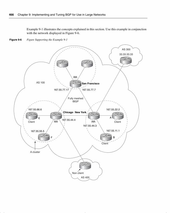
466 Chapter 9: Implementing and Tuning BGP for Use in Large Networks
Example 9-1 illustrates the concepts explained in this section. Use this example in conjunction with the network displayed in Figure 9-6.
Figure 9-6 Figure Supporting the Example 9-1
Fully meshedIBGP
A cluster
AS 100
RR
RR RR
167.55.77.7167.55.77.17
San Francisco
Chicago New York
167.55.44.4
167.55.44.3
167.55.22.2
167.55.11.1
167.55.66.6
167.55.55.5
E
F
Client Client
A
B
AS 300
33.33.33.33
AS 400
Non client
Client
chpt_01.book Page 466 Thursday, December 21, 2000 6:22 PM
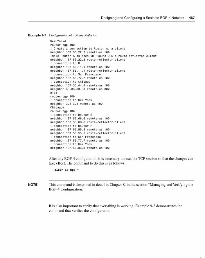
Designing and Configuring a Scalable BGP-4 Network 467
After any BGP-4 configuration, it is necessary to reset the TCP session so that the changes can take effect. The command to do this is as follows:
clear ip bgp *
NOTE This command is described in detail in Chapter 8, in the section “Managing and Verifying the BGP-4 Configuration.”
It is also important to verify that everything is working. Example 9-2 demonstrates the command that verifies the configuration.
Example 9-1 Configuration of a Route Reflector
New York#router bgp 100! Create a connection to Router A, a clientneighbor 167.55.22.2 remote-as 100 !make Router A as seen in Figure 9-6 a route reflector clientneighbor 167.55.22.2 route-reflector-client! connection to Bneighbor 167.55.11.1 remote-as 100neighbor 167.55.11.1 route-reflector-client! connection to San Francisconeighbor 167.55.77.7 remote-as 100! connection to Chicagoneighbor 167.55.44.4 remote-as 100neighbor 33.33.33.33 remote-as 300RTB#router bgp 100! connection to New Yorkneighbor 3.3.3.3 remote-as 100Chicago#router bgp 100! connection to Router Eneighbor 167.55.66.6 remote-as 100neighbor 167.55.66.6 route-reflector-client! connection to Router Fneighbor 167.55.55.5 remote-as 100neighbor 167.55.55.5 route-reflector-client! connection to San Francisconeighbor 167.55.77.7 remote-as 100! connection to New Yorkneighbor 167.55.33.3 remote-as 100
chpt_01.book Page 467 Thursday, December 21, 2000 6:22 PM
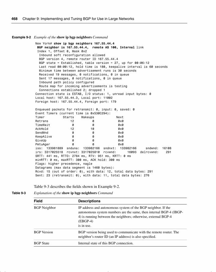
468 Chapter 9: Implementing and Tuning BGP for Use in Large Networks
Table 9-3 describes the fields shown in Example 9-2.
Example 9-2 Example of the show ip bgp neighbors Command
New York# show ip bgp neighbors 167.55.44.4 BGP neighbor is 167.55.44.4, remote AS 100, Internal link Index 1, Offset 0, Mask 0x2 Inbound soft reconfiguration allowed BGP version 4, remote router ID 167.55.44.4 BGP state = Established, table version = 27, up for 00:06:12 Last read 00:00:12, hold time is 180, keepalive interval is 60 seconds Minimum time between advertisement runs is 30 seconds Received 19 messages, 0 notifications, 0 in queue Sent 17 messages, 0 notifications, 0 in queue Inbound path policy configured Route map for incoming advertisements is testing Connections established 2; dropped 1Connection state is ESTAB, I/O status: 1, unread input bytes: 0Local host: 167.55.44.3, Local port: 11002Foreign host: 167.55.44.4, Foreign port: 179 Enqueued packets for retransmit: 0, input: 0, saved: 0Event Timers (current time is 0x530C294):Timer Starts Wakeups NextRetrans 12 0 0x0TimeWait 0 0 0x0AckHold 12 10 0x0SendWnd 0 0 0x0KeepAlive 0 0 0x0GiveUp 0 0 0x0PmtuAger 0 0 0x0iss: 133981889 snduna: 133982166 sndnxt: 133982166 sndwnd: 16108irs: 3317025518 rcvnxt: 3317025810 rcvwnd: 16093 delrcvwnd: 291SRTT: 441 ms, RTTO: 2784 ms, RTV: 951 ms, KRTT: 0 msminRTT: 0 ms, maxRTT: 300 ms, ACK hold: 300 msFlags: higher precedence, nagleDatagrams (max data segment is 1460 bytes):Rcvd: 15 (out of order: 0), with data: 12, total data bytes: 291Sent: 23 (retransmit: 0), with data: 11, total data bytes: 276
Table 9-3 Explanation of the show ip bgp neighbors Command
Field Descriptions
BGP Neighbor IP address and autonomous system of the BGP neighbor. If the autonomous system numbers are the same, then internal BGP-4 (IBGP-4) is running between the neighbors; otherwise, external BGP-4 (EBGP-4) is in use.
BGP Version BGP version being used to communicate with the remote router. The neighbor’s router ID (an IP address) is also specified.
BGP State Internal state of this BGP connection.
chpt_01.book Page 468 Thursday, December 21, 2000 6:22 PM
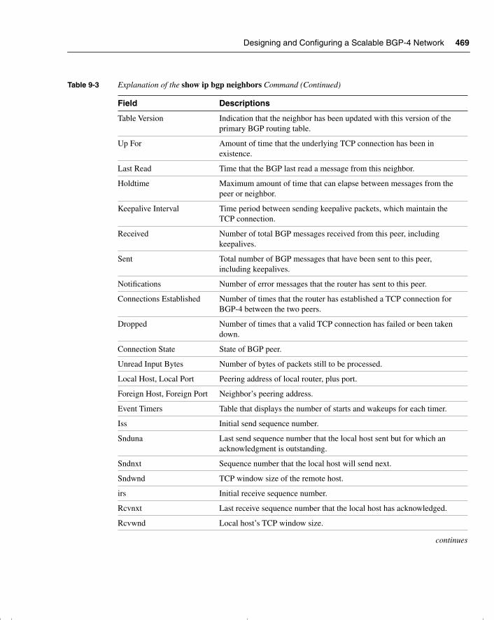
Designing and Configuring a Scalable BGP-4 Network 469
Table Version Indication that the neighbor has been updated with this version of the primary BGP routing table.
Up For Amount of time that the underlying TCP connection has been in existence.
Last Read Time that the BGP last read a message from this neighbor.
Holdtime Maximum amount of time that can elapse between messages from the peer or neighbor.
Keepalive Interval Time period between sending keepalive packets, which maintain the TCP connection.
Received Number of total BGP messages received from this peer, including keepalives.
Sent Total number of BGP messages that have been sent to this peer, including keepalives.
Notifications Number of error messages that the router has sent to this peer.
Connections Established Number of times that the router has established a TCP connection for BGP-4 between the two peers.
Dropped Number of times that a valid TCP connection has failed or been taken down.
Connection State State of BGP peer.
Unread Input Bytes Number of bytes of packets still to be processed.
Local Host, Local Port Peering address of local router, plus port.
Foreign Host, Foreign Port Neighbor’s peering address.
Event Timers Table that displays the number of starts and wakeups for each timer.
Iss Initial send sequence number.
Snduna Last send sequence number that the local host sent but for which an acknowledgment is outstanding.
Sndnxt Sequence number that the local host will send next.
Sndwnd TCP window size of the remote host.
irs Initial receive sequence number.
Rcvnxt Last receive sequence number that the local host has acknowledged.
Rcvwnd Local host’s TCP window size.
continues
Table 9-3 Explanation of the show ip bgp neighbors Command (Continued)
Field Descriptions
chpt_01.book Page 469 Thursday, December 21, 2000 6:22 PM
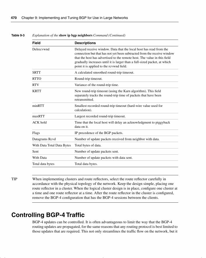
470 Chapter 9: Implementing and Tuning BGP for Use in Large Networks
TIP When implementing clusters and route reflectors, select the route reflector carefully in accordance with the physical topology of the network. Keep the design simple, placing one route reflector in a cluster. When the logical cluster design is in place, configure one cluster at a time and one route reflector at a time. After the route reflector in the cluster is configured, remove the BGP-4 configuration that has the BGP-4 sessions between the clients.
Controlling BGP-4 TrafficBGP-4 updates can be controlled. It is often advantageous to limit the way that the BGP-4 routing updates are propagated, for the same reasons that any routing protocol is best limited to those updates that are required. This not only streamlines the traffic flow on the network, but it
Delrecvwnd Delayed receive window. Data that the local host has read from the connection but that has not yet been subtracted from the receive window that the host has advertised to the remote host. The value in this field gradually increases until it is larger than a full-sized packet, at which point it is applied to the rcvwnd field.
SRTT A calculated smoothed round-trip timeout.
RTTO Round-trip timeout.
RTV Variance of the round-trip time.
KRTT New round-trip timeout (using the Karn algorithm). This field separately tracks the round-trip time of packets that have been retransmitted.
minRTT Smallest recorded round-trip timeout (hard-wire value used for calculation).
maxRTT Largest recorded round-trip timeout.
ACK hold Time that the local host will delay an acknowledgment to piggyback data on it.
Flags IP precedence of the BGP packets.
Datagrams Rcvd Number of update packets received from neighbor with data.
With Data Total Data Bytes Total bytes of data.
Sent Number of update packets sent.
With Data Number of update packets with data sent.
Total data bytes Total data bytes.
Table 9-3 Explanation of the show ip bgp neighbors Command (Continued)
Field Descriptions
chpt_01.book Page 470 Thursday, December 21, 2000 6:22 PM
Controlling BGP-4 Traffic 471
also simplifies the network and thus its maintenance. Designing how the routing information should be forwarded through the network forms a basic level of security and can reduce the possibility of routing loops.
Filtering is essentially traffic control. There are three main flavors of filtering on a Cisco router:
• Access list—This is used in BGP-4 for the creation of route maps, forming the “what if” logic of the route map. An access list is also used in BGP-4 to filter updates sent from a peer based on the autonomous system path. In addition, other technologies use access lists for standard filtering.
• Prefix list/distribute list—Distribute lists filter routing updates, particularly in redistribution. From Cisco IOS version 11.2, ISPs were given prefix lists, which are a more efficient form of filtering. Prefix lists filter based on the prefix of the address. This option was made a part of the general release IOS in version 12.0. Both prefix lists and distribute lists filter on network numbers, not autonomous system paths, for which access lists are used.
• Route maps—A route map is a sophisticated access list that defines criteria upon which a router acts when a match is found for the stated criteria. It is used in BGP-4 for setting the attributes that determine the basis for selecting the best path to a destination.
Prefix lists were introduced to BGP-4 because they are a very efficient form of filtering. Because they search on the prefix of the address as defined by the administrator, the lookup is very fast. This is particularly important in the potentially huge routing tables that can be generated in BGP-4 networks.
Another great advantage to prefix lists is the capability to edit them, particularly if they become large. Access lists cannot be dynamically edited unless they are ported to an application that allows them to be edited.
Ease of use is the main difference that the users experience. This is not only true with the editing features, but also with the improved interface, which affords greater flexibility.
How Prefix Lists WorkBefore using a prefix list in a command, you must set up a prefix list. Each line in the prefix list is associated with a sequence number, similar to the number identifying a line of code in a computer program. The editing of the prefix list is achieved by referencing the line or sequence number. This is not available in access lists, which requires the rewriting of the entire list, unless you have the forethought to cut and paste the configuration file into a word processor. In planning the prefix list, it is advisable to assign sequence numbers to the entries in the prefix list in accordance with the rules by which prefix lists are processed.
chpt_01.book Page 471 Thursday, December 21, 2000 6:22 PM
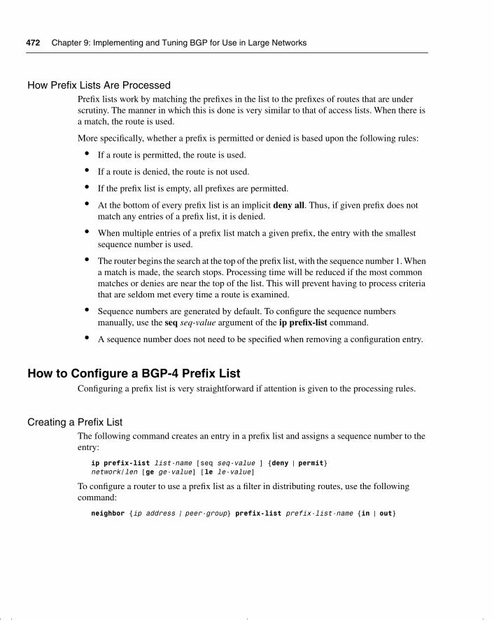
472 Chapter 9: Implementing and Tuning BGP for Use in Large Networks
How Prefix Lists Are ProcessedPrefix lists work by matching the prefixes in the list to the prefixes of routes that are under scrutiny. The manner in which this is done is very similar to that of access lists. When there is a match, the route is used.
More specifically, whether a prefix is permitted or denied is based upon the following rules:
• If a route is permitted, the route is used.
• If a route is denied, the route is not used.
• If the prefix list is empty, all prefixes are permitted.
• At the bottom of every prefix list is an implicit deny all. Thus, if given prefix does not match any entries of a prefix list, it is denied.
• When multiple entries of a prefix list match a given prefix, the entry with the smallest sequence number is used.
• The router begins the search at the top of the prefix list, with the sequence number 1. When a match is made, the search stops. Processing time will be reduced if the most common matches or denies are near the top of the list. This will prevent having to process criteria that are seldom met every time a route is examined.
• Sequence numbers are generated by default. To configure the sequence numbers manually, use the seq seq-value argument of the ip prefix-list command.
• A sequence number does not need to be specified when removing a configuration entry.
How to Configure a BGP-4 Prefix ListConfiguring a prefix list is very straightforward if attention is given to the processing rules.
Creating a Prefix ListThe following command creates an entry in a prefix list and assigns a sequence number to the entry:
ip prefix-list list-name [seq seq-value ] {deny | permit}network/len [ge ge-value] [le le-value]
To configure a router to use a prefix list as a filter in distributing routes, use the following command:
neighbor {ip address | peer-group} prefix-list prefix-list-name {in | out}
chpt_01.book Page 472 Thursday, December 21, 2000 6:22 PM
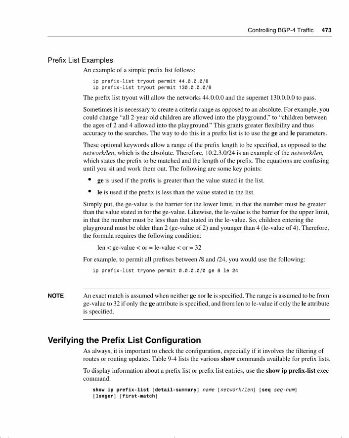
Controlling BGP-4 Traffic 473
Prefix List Examples An example of a simple prefix list follows:
ip prefix-list tryout permit 44.0.0.0/8ip prefix-list tryout permit 130.0.0.0/8
The prefix list tryout will allow the networks 44.0.0.0 and the supernet 130.0.0.0 to pass.
Sometimes it is necessary to create a criteria range as opposed to an absolute. For example, you could change “all 2-year-old children are allowed into the playground,” to “children between the ages of 2 and 4 allowed into the playground.” This grants greater flexibility and thus accuracy to the searches. The way to do this in a prefix list is to use the ge and le parameters.
These optional keywords allow a range of the prefix length to be specified, as opposed to the network/len, which is the absolute. Therefore, 10.2.3.0/24 is an example of the network/len, which states the prefix to be matched and the length of the prefix. The equations are confusing until you sit and work them out. The following are some key points:
• ge is used if the prefix is greater than the value stated in the list.
• le is used if the prefix is less than the value stated in the list.
Simply put, the ge-value is the barrier for the lower limit, in that the number must be greater than the value stated in for the ge-value. Likewise, the le-value is the barrier for the upper limit, in that the number must be less than that stated in the le-value. So, children entering the playground must be older than 2 (ge-value of 2) and younger than 4 (le-value of 4). Therefore, the formula requires the following condition:
len < ge-value < or = le-value < or = 32
For example, to permit all prefixes between /8 and /24, you would use the following:
ip prefix-list tryone permit 0.0.0.0/0 ge 8 le 24
NOTE An exact match is assumed when neither ge nor le is specified. The range is assumed to be from ge-value to 32 if only the ge attribute is specified, and from len to le-value if only the le attribute is specified.
Verifying the Prefix List ConfigurationAs always, it is important to check the configuration, especially if it involves the filtering of routes or routing updates. Table 9-4 lists the various show commands available for prefix lists.
To display information about a prefix list or prefix list entries, use the show ip prefix-list exec command:
show ip prefix-list [detail-summary] name [network/len] [seq seq-num][longer] [first-match]
chpt_01.book Page 473 Thursday, December 21, 2000 6:22 PM
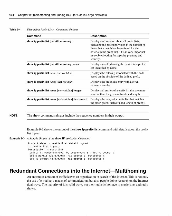
474 Chapter 9: Implementing and Tuning BGP for Use in Large Networks
NOTE The show commands always include the sequence numbers in their output.
Example 9-3 shows the output of the show ip prefix-list command with details about the prefix list tryout.
Redundant Connections into the Internet—MultihomingAn enormous amount of traffic leaves an organization in search of the Internet. This is not only the use of e-mail as a means of communication, but also people doing research on the Internet tidal wave. The majority of it is valid work, not the ritualistic homage to music sites and radio shows.
Table 9-4 Displaying Prefix Lists—Command Options
Command Description
show ip prefix-list [detail | summary] Displays information about all prefix lists, including the hit count, which is the number of times that a match has been found for the criteria in the prefix list. This is very important in troubleshooting for capacity planning and security.
show ip prefix-list [detail | summary] name Displays a table showing the entries in a prefix list identified by name.
show ip prefix-list name [network/len] Displays the filtering associated with the node based on the absolute of the defined prefix.
show ip prefix-list name [seq seq-num] Displays the prefix list entry with a given sequence number.
show ip prefix-list name [network/len] longer Displays all entries of a prefix list that are more specific than the given network and length.
show ip prefix-list name [network/len] first-match Displays the entry of a prefix list that matches the given prefix (network and length of prefix).
Example 9-3 A Sample Output of the show IP prefix-list Command
Router# show ip prefix-list detail tryoutip prefix-list tryout:Description: tryout-list count: 1, range entries: 0, sequences: 5 - 10, refcount: 3 seq 5 permit 130.0.0.0/8 (hit count: 0, refcount: 1) seq 10 permit 44.0.0.0/8 (hit count: 0, refcount: 1)
chpt_01.book Page 474 Thursday, December 21, 2000 6:22 PM
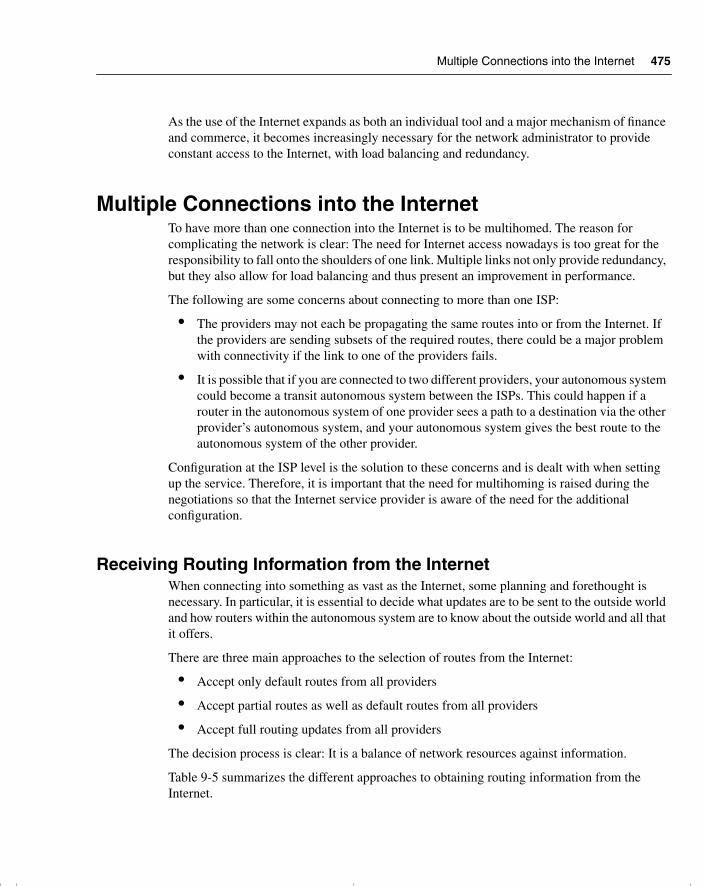
Multiple Connections into the Internet 475
As the use of the Internet expands as both an individual tool and a major mechanism of finance and commerce, it becomes increasingly necessary for the network administrator to provide constant access to the Internet, with load balancing and redundancy.
Multiple Connections into the InternetTo have more than one connection into the Internet is to be multihomed. The reason for complicating the network is clear: The need for Internet access nowadays is too great for the responsibility to fall onto the shoulders of one link. Multiple links not only provide redundancy, but they also allow for load balancing and thus present an improvement in performance.
The following are some concerns about connecting to more than one ISP:
• The providers may not each be propagating the same routes into or from the Internet. If the providers are sending subsets of the required routes, there could be a major problem with connectivity if the link to one of the providers fails.
• It is possible that if you are connected to two different providers, your autonomous system could become a transit autonomous system between the ISPs. This could happen if a router in the autonomous system of one provider sees a path to a destination via the other provider’s autonomous system, and your autonomous system gives the best route to the autonomous system of the other provider.
Configuration at the ISP level is the solution to these concerns and is dealt with when setting up the service. Therefore, it is important that the need for multihoming is raised during the negotiations so that the Internet service provider is aware of the need for the additional configuration.
Receiving Routing Information from the InternetWhen connecting into something as vast as the Internet, some planning and forethought is necessary. In particular, it is essential to decide what updates are to be sent to the outside world and how routers within the autonomous system are to know about the outside world and all that it offers.
There are three main approaches to the selection of routes from the Internet:
• Accept only default routes from all providers
• Accept partial routes as well as default routes from all providers
• Accept full routing updates from all providers
The decision process is clear: It is a balance of network resources against information.
Table 9-5 summarizes the different approaches to obtaining routing information from the Internet.
chpt_01.book Page 475 Thursday, December 21, 2000 6:22 PM
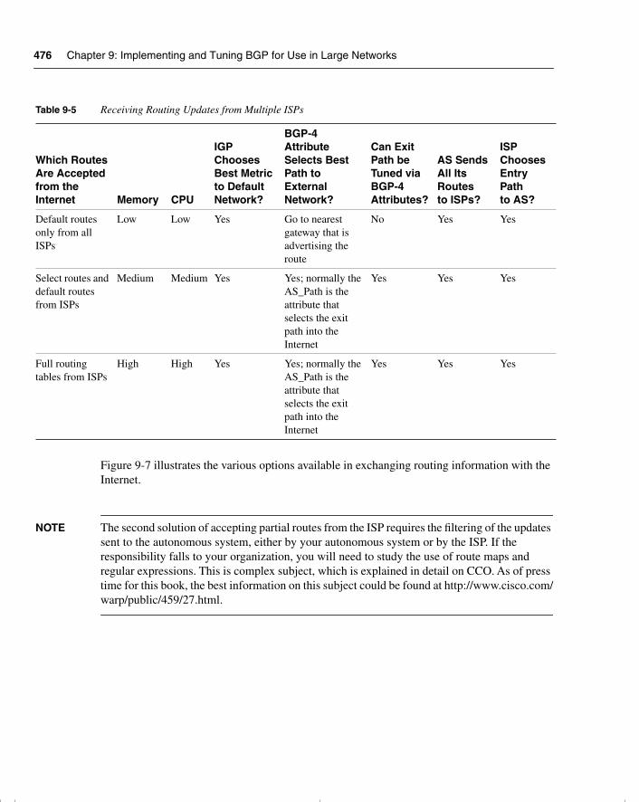
476 Chapter 9: Implementing and Tuning BGP for Use in Large Networks
Figure 9-7 illustrates the various options available in exchanging routing information with the Internet.
NOTE The second solution of accepting partial routes from the ISP requires the filtering of the updates sent to the autonomous system, either by your autonomous system or by the ISP. If the responsibility falls to your organization, you will need to study the use of route maps and regular expressions. This is complex subject, which is explained in detail on CCO. As of press time for this book, the best information on this subject could be found at http://www.cisco.com/warp/public/459/27.html.
Table 9-5 Receiving Routing Updates from Multiple ISPs
Which RoutesAre Acceptedfrom the Internet Memory CPU
IGP ChoosesBest Metric to DefaultNetwork?
BGP-4 AttributeSelects Best Path to ExternalNetwork?
Can Exit Path be Tuned viaBGP-4Attributes?
AS Sends All Its Routes to ISPs?
ISPChoosesEntry Pathto AS?
Default routes only from all ISPs
Low Low Yes Go to nearest gateway that is advertising the route
No Yes Yes
Select routes and default routes from ISPs
Medium Medium Yes Yes; normally the AS_Path is the attribute that selects the exit path into the Internet
Yes Yes Yes
Full routing tables from ISPs
High High Yes Yes; normally the AS_Path is the attribute that selects the exit path into the Internet
Yes Yes Yes
chpt_01.book Page 476 Thursday, December 21, 2000 6:22 PM
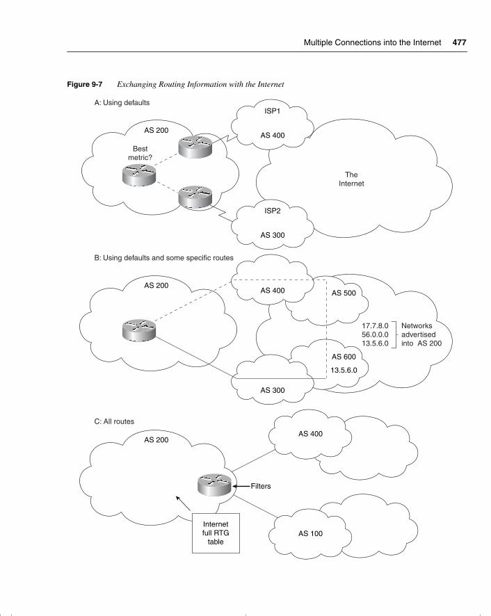
Multiple Connections into the Internet 477
Figure 9-7 Exchanging Routing Information with the Internet
AS 600
13.5.6.0
AS 500
17.7.8.056.0.0.013.5.6.0
Networksadvertisedinto AS 200
AS 200
Bestmetric?
AS 300
ISP2
ISP1
AS 400
TheInternet
A: Using defaults
AS 300
AS 400
B: Using defaults and some specific routes
C: All routes
AS 200
AS 100
AS 400AS 200
Internetfull RTG
table
Filters
chpt_01.book Page 477 Thursday, December 21, 2000 6:22 PM
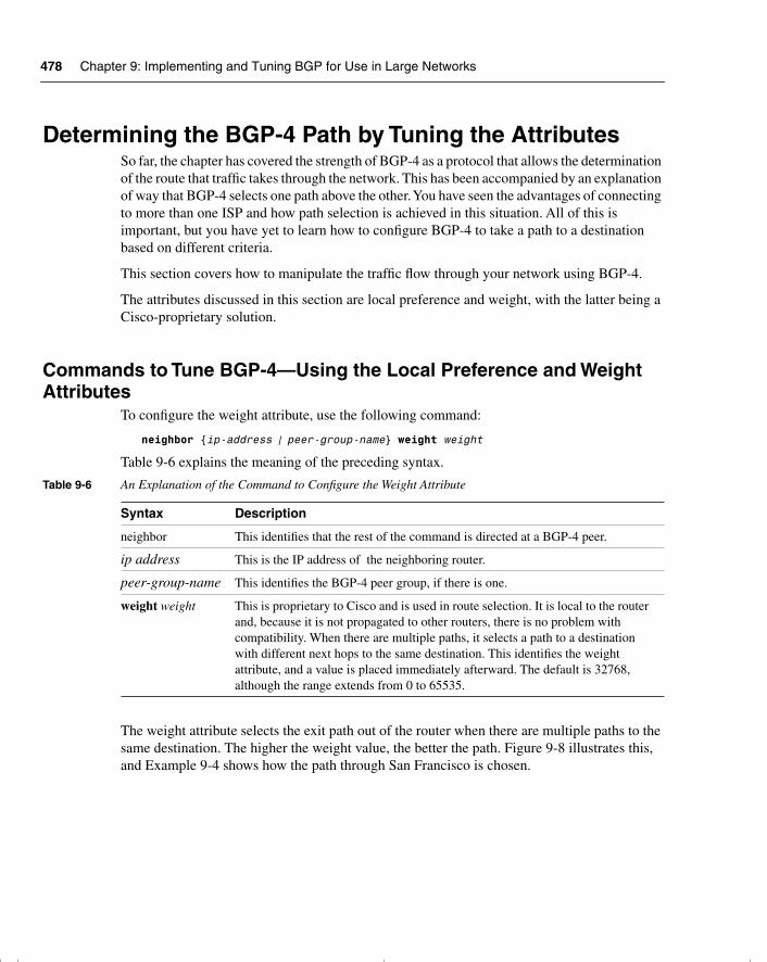
478 Chapter 9: Implementing and Tuning BGP for Use in Large Networks
Determining the BGP-4 Path by Tuning the AttributesSo far, the chapter has covered the strength of BGP-4 as a protocol that allows the determination of the route that traffic takes through the network. This has been accompanied by an explanation of way that BGP-4 selects one path above the other. You have seen the advantages of connecting to more than one ISP and how path selection is achieved in this situation. All of this is important, but you have yet to learn how to configure BGP-4 to take a path to a destination based on different criteria.
This section covers how to manipulate the traffic flow through your network using BGP-4.
The attributes discussed in this section are local preference and weight, with the latter being a Cisco-proprietary solution.
Commands to Tune BGP-4—Using the Local Preference and Weight Attributes
To configure the weight attribute, use the following command:
neighbor {ip-address | peer-group-name} weight weight
Table 9-6 explains the meaning of the preceding syntax.
The weight attribute selects the exit path out of the router when there are multiple paths to the same destination. The higher the weight value, the better the path. Figure 9-8 illustrates this, and Example 9-4 shows how the path through San Francisco is chosen.
Table 9-6 An Explanation of the Command to Configure the Weight Attribute
Syntax Description
neighbor This identifies that the rest of the command is directed at a BGP-4 peer.
ip address This is the IP address of the neighboring router.
peer-group-name This identifies the BGP-4 peer group, if there is one.
weight weight This is proprietary to Cisco and is used in route selection. It is local to the router and, because it is not propagated to other routers, there is no problem with compatibility. When there are multiple paths, it selects a path to a destination with different next hops to the same destination. This identifies the weight attribute, and a value is placed immediately afterward. The default is 32768, although the range extends from 0 to 65535.
chpt_01.book Page 478 Thursday, December 21, 2000 6:22 PM
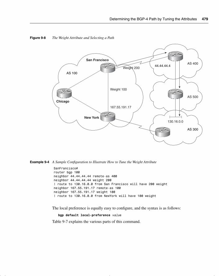
Determining the BGP-4 Path by Tuning the Attributes 479
Figure 9-8 The Weight Attribute and Selecting a Path
The local preference is equally easy to configure, and the syntax is as follows:
bgp default local-preference value
Table 9-7 explains the various parts of this command.
Example 9-4 A Sample Configuration to Illustrate How to Tune the Weight Attribute
SanFrancisco# router bgp 100 neighbor 44.44.44.44 remote-as 400 neighbor 44.44.44.44 weight 200 ! route to 130.16.0.0 from San Francisco will have 200 weightneighbor 167.55.191.17 remote-as 100 neighbor 167.55.191.17 weight 100 ! route to 130.16.0.0 from NewYork will have 100 weight
AS 100
Chicago
New York
San Francisco
Weight 200
Weight 100
167.55.191.17
AS 40044.44.44.4
AS 500
AS 300
130.16.0.0
chpt_01.book Page 479 Thursday, December 21, 2000 6:22 PM
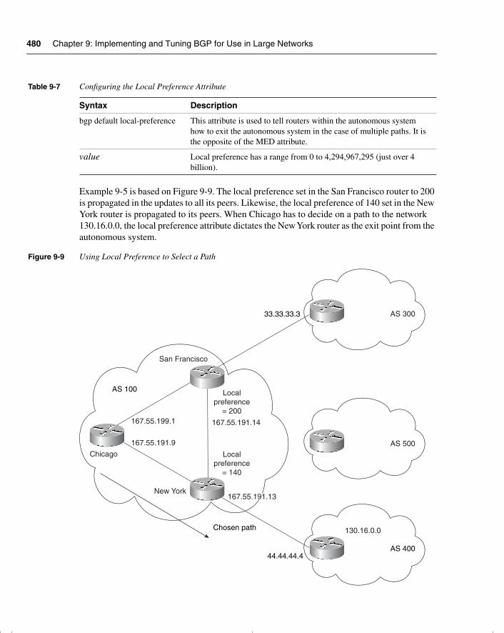
480 Chapter 9: Implementing and Tuning BGP for Use in Large Networks
Example 9-5 is based on Figure 9-9. The local preference set in the San Francisco router to 200 is propagated in the updates to all its peers. Likewise, the local preference of 140 set in the New York router is propagated to its peers. When Chicago has to decide on a path to the network 130.16.0.0, the local preference attribute dictates the New York router as the exit point from the autonomous system.
Figure 9-9 Using Local Preference to Select a Path
Table 9-7 Configuring the Local Preference Attribute
Syntax Description
bgp default local-preference This attribute is used to tell routers within the autonomous system how to exit the autonomous system in the case of multiple paths. It is the opposite of the MED attribute.
value Local preference has a range from 0 to 4,294,967,295 (just over 4 billion).
AS 100
Chicago
New York
San Francisco
Localpreference
= 200
Localpreference
= 140
AS 500
AS 400
130.16.0.0
AS 30033.33.33.3
44.44.44.4
Chosen path
167.55.191.13
167.55.191.14167.55.199.1
167.55.191.9
chpt_01.book Page 480 Thursday, December 21, 2000 6:22 PM
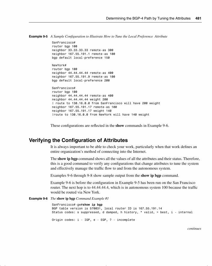
Determining the BGP-4 Path by Tuning the Attributes 481
These configurations are reflected in the show commands in Example 9-6.
Verifying the Configuration of AttributesIt is always important to be able to check your work, particularly when that work defines an entire organization’s method of connecting into the Internet.
The show ip bgp command shows all the values of all the attributes and their status. Therefore, this is a good command to verify any configurations that change attributes to tune the system and effectively manage the traffic flow to and from the autonomous system.
Examples 9-6 through 9-8 show sample output from the show ip bgp command.
Example 9-6 is before the configuration in Example 9-5 has been run on the San Francisco router. The next hop is to 44.44.44.4, which is in autonomous system 100 because the traffic would be routed via New York.
Example 9-5 A Sample Configuration to Illustrate How to Tune the Local Preference Attribute
SanFrancisco# router bgp 100neighbor 33.33.33.33 remote-as 300 neighbor 167.55.191.1 remote-as 100 bgp default local-preference 150
NewYork# router bgp 100neighbor 44.44.44.44 remote-as 400neighbor 167.55.191.9 remote-as 100 bgp default local-preference 200
SanFrancisco#router bgp 100neighbor 44.44.44.44 remote-as 400neighbor 44.44.44.44 weight 200 ! route to 130.16.0.0 from SanFrancisco will have 200 weightneighbor 167.55.191.17 remote-as 100neighbor 167.55.191.17 weight 140 !route to 130.16.0.0 from NewYork will have 140 weight
Example 9-6 The show ip bgp Command Example #1
SanFrancisco#-gw#show ip bgpBGP table version is 570031, local router ID is 167.55.191.14Status codes: s suppressed, d damped, h history, * valid, > best, i - internal
Origin codes: i - IGP, e - EGP, ? - incomplete
continues
chpt_01.book Page 481 Thursday, December 21, 2000 6:22 PM
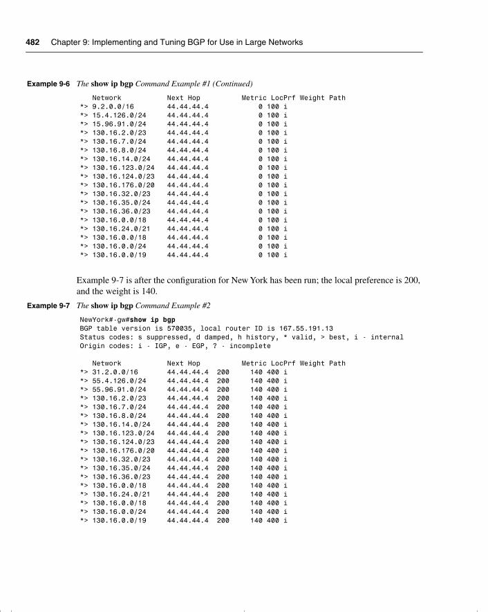
482 Chapter 9: Implementing and Tuning BGP for Use in Large Networks
Example 9-7 is after the configuration for New York has been run; the local preference is 200, and the weight is 140.
Network Next Hop Metric LocPrf Weight Path*> 9.2.0.0/16 44.44.44.4 0 100 i*> 15.4.126.0/24 44.44.44.4 0 100 i*> 15.96.91.0/24 44.44.44.4 0 100 i*> 130.16.2.0/23 44.44.44.4 0 100 i*> 130.16.7.0/24 44.44.44.4 0 100 i*> 130.16.8.0/24 44.44.44.4 0 100 i*> 130.16.14.0/24 44.44.44.4 0 100 i*> 130.16.123.0/24 44.44.44.4 0 100 i*> 130.16.124.0/23 44.44.44.4 0 100 i*> 130.16.176.0/20 44.44.44.4 0 100 i*> 130.16.32.0/23 44.44.44.4 0 100 i*> 130.16.35.0/24 44.44.44.4 0 100 i*> 130.16.36.0/23 44.44.44.4 0 100 i*> 130.16.0.0/18 44.44.44.4 0 100 i*> 130.16.24.0/21 44.44.44.4 0 100 i*> 130.16.0.0/18 44.44.44.4 0 100 i*> 130.16.0.0/24 44.44.44.4 0 100 i*> 130.16.0.0/19 44.44.44.4 0 100 i
Example 9-7 The show ip bgp Command Example #2
NewYork#-gw#show ip bgpBGP table version is 570035, local router ID is 167.55.191.13Status codes: s suppressed, d damped, h history, * valid, > best, i - internalOrigin codes: i - IGP, e - EGP, ? - incomplete
Network Next Hop Metric LocPrf Weight Path*> 31.2.0.0/16 44.44.44.4 200 140 400 i*> 55.4.126.0/24 44.44.44.4 200 140 400 i*> 55.96.91.0/24 44.44.44.4 200 140 400 i*> 130.16.2.0/23 44.44.44.4 200 140 400 i*> 130.16.7.0/24 44.44.44.4 200 140 400 i*> 130.16.8.0/24 44.44.44.4 200 140 400 i*> 130.16.14.0/24 44.44.44.4 200 140 400 i*> 130.16.123.0/24 44.44.44.4 200 140 400 i*> 130.16.124.0/23 44.44.44.4 200 140 400 i*> 130.16.176.0/20 44.44.44.4 200 140 400 i*> 130.16.32.0/23 44.44.44.4 200 140 400 i*> 130.16.35.0/24 44.44.44.4 200 140 400 i*> 130.16.36.0/23 44.44.44.4 200 140 400 i*> 130.16.0.0/18 44.44.44.4 200 140 400 i*> 130.16.24.0/21 44.44.44.4 200 140 400 i*> 130.16.0.0/18 44.44.44.4 200 140 400 i*> 130.16.0.0/24 44.44.44.4 200 140 400 i*> 130.16.0.0/19 44.44.44.4 200 140 400 i
Example 9-6 The show ip bgp Command Example #1 (Continued)
chpt_01.book Page 482 Thursday, December 21, 2000 6:22 PM
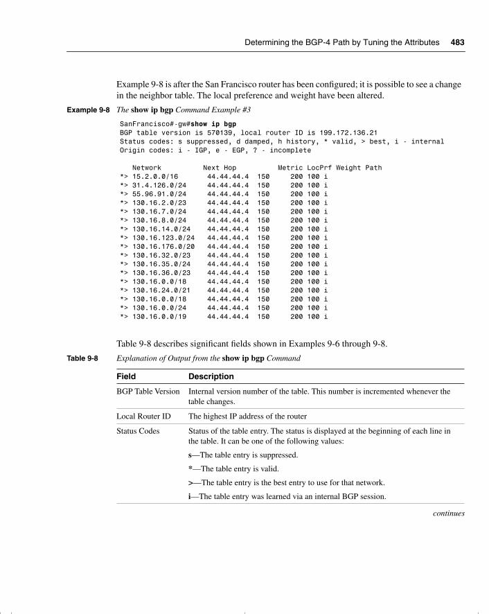
Determining the BGP-4 Path by Tuning the Attributes 483
Example 9-8 is after the San Francisco router has been configured; it is possible to see a change in the neighbor table. The local preference and weight have been altered.
Table 9-8 describes significant fields shown in Examples 9-6 through 9-8.
Example 9-8 The show ip bgp Command Example #3
SanFrancisco#-gw#show ip bgpBGP table version is 570139, local router ID is 199.172.136.21Status codes: s suppressed, d damped, h history, * valid, > best, i - internalOrigin codes: i - IGP, e - EGP, ? - incomplete
Network Next Hop Metric LocPrf Weight Path*> 15.2.0.0/16 44.44.44.4 150 200 100 i*> 31.4.126.0/24 44.44.44.4 150 200 100 i*> 55.96.91.0/24 44.44.44.4 150 200 100 i*> 130.16.2.0/23 44.44.44.4 150 200 100 i*> 130.16.7.0/24 44.44.44.4 150 200 100 i*> 130.16.8.0/24 44.44.44.4 150 200 100 i*> 130.16.14.0/24 44.44.44.4 150 200 100 i*> 130.16.123.0/24 44.44.44.4 150 200 100 i*> 130.16.176.0/20 44.44.44.4 150 200 100 i*> 130.16.32.0/23 44.44.44.4 150 200 100 i*> 130.16.35.0/24 44.44.44.4 150 200 100 i*> 130.16.36.0/23 44.44.44.4 150 200 100 i*> 130.16.0.0/18 44.44.44.4 150 200 100 i*> 130.16.24.0/21 44.44.44.4 150 200 100 i*> 130.16.0.0/18 44.44.44.4 150 200 100 i*> 130.16.0.0/24 44.44.44.4 150 200 100 i*> 130.16.0.0/19 44.44.44.4 150 200 100 i
Table 9-8 Explanation of Output from the show ip bgp Command
Field Description
BGP Table Version Internal version number of the table. This number is incremented whenever the table changes.
Local Router ID The highest IP address of the router
Status Codes Status of the table entry. The status is displayed at the beginning of each line in the table. It can be one of the following values:
s—The table entry is suppressed.
*—The table entry is valid.
>—The table entry is the best entry to use for that network.
i—The table entry was learned via an internal BGP session.
continues
chpt_01.book Page 483 Thursday, December 21, 2000 6:22 PM
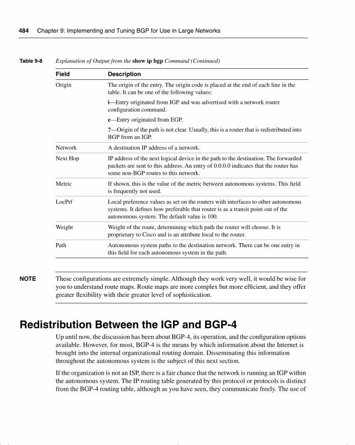
484 Chapter 9: Implementing and Tuning BGP for Use in Large Networks
NOTE These configurations are extremely simple. Although they work very well, it would be wise for you to understand route maps. Route maps are more complex but more efficient, and they offer greater flexibility with their greater level of sophistication.
Redistribution Between the IGP and BGP-4Up until now, the discussion has been about BGP-4, its operation, and the configuration options available. However, for most, BGP-4 is the means by which information about the Internet is brought into the internal organizational routing domain. Disseminating this information throughout the autonomous system is the subject of this next section.
If the organization is not an ISP, there is a fair chance that the network is running an IGP within the autonomous system. The IP routing table generated by this protocol or protocols is distinct from the BGP-4 routing table, although as you have seen, they communicate freely. The use of
Origin The origin of the entry. The origin code is placed at the end of each line in the table. It can be one of the following values:
i—Entry originated from IGP and was advertised with a network router configuration command.
e—Entry originated from EGP.
?—Origin of the path is not clear. Usually, this is a router that is redistributed into BGP from an IGP.
Network A destination IP address of a network.
Next Hop IP address of the next logical device in the path to the destination. The forwarded packets are sent to this address. An entry of 0.0.0.0 indicates that the router has some non-BGP routes to this network.
Metric If shown, this is the value of the metric between autonomous systems. This field is frequently not used.
LocPrf Local preference values as set on the routers with interfaces to other autonomous systems. It defines how preferable that router is as a transit point out of the autonomous system. The default value is 100.
Weight Weight of the route, determining which path the router will choose. It is proprietary to Cisco and is an attribute local to the router.
Path Autonomous system paths to the destination network. There can be one entry in this field for each autonomous system in the path.
Table 9-8 Explanation of Output from the show ip bgp Command (Continued)
Field Description
chpt_01.book Page 484 Thursday, December 21, 2000 6:22 PM
Redistribution Between the IGP and BGP-4 485
synchronization is a case in point. However, populating these tables with routes from the other table needs to be manually configured.
Obviously, routes can be injected from the IGP into BGP-4, or from the BGP-4 into the IGP.
Advertising Routes from an IGP into BGP-4 First, consider the advertising routes into BGP-4. There are three ways of populating the BGP-4 table with IGP routes:
• Using the network command—This is used to advertise routes that are in the IP routing table.
• Redistributing static routes—These are routes that have been summarized to a supernet, such as a Class C address with a prefix mask of 16 bits. This requires statically routing to null 0. This fools the system by creating a route that has no exit point from the router because the route does not exist. The command places the route into the routing table without fear of it being used and creating a black hole. This is because lookups are based on the longest match, and the outgoing interface is null 0, which is nowhere.
The problem is that if the route in the IGP routing table disappears, BGP-4 still advertises the route, causing traffic to journey into the autonomous system only to die. Therefore, Cisco suggests that you use the aggregate-address command for BGP-4 instead.
• Redistributing dynamically learned routes from the IGP—This configuration is not advised because there is a great reliance on the IGP table. It is imperative that external routes carried in IBGP-4 are filtered out; otherwise, routing loops are generated when BGP-4 routes are fed into IGP, only to be advertised back into BGP-4 further down the network.
Advertising Routes from a BGP-4 into an IGPRedistributing the routes from the Internet into a small network is bizarre. What makes it so alarming is how large the Internet is and how enormous the routing tables are, even with the large amount of aggregation and filtering. There is still a lot of information to carry over.
Do ISPs Need to Redistribute Paths from BGP-4 into the IGP? Because ISPs tend to run EBGP-4 and IBGP-4 extensively, they tend to run these exclusively for exterior routes, using an IGP only for internal routes. This requires no redistribution, which is easier for the routers and means the following:
• Redistribution is not necessary, and the resources are spared.
• The IGP routing table is spared.
• BGP-4 can converge faster because it does not have to wait for a hello.
chpt_01.book Page 485 Thursday, December 21, 2000 6:22 PM
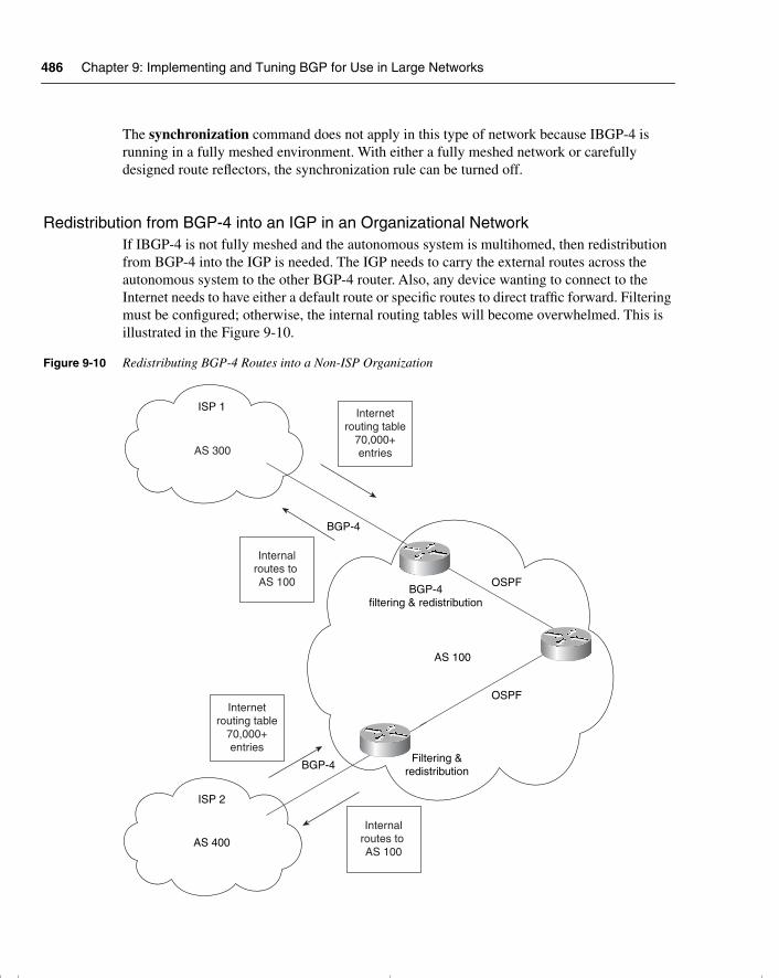
486 Chapter 9: Implementing and Tuning BGP for Use in Large Networks
The synchronization command does not apply in this type of network because IBGP-4 is running in a fully meshed environment. With either a fully meshed network or carefully designed route reflectors, the synchronization rule can be turned off.
Redistribution from BGP-4 into an IGP in an Organizational NetworkIf IBGP-4 is not fully meshed and the autonomous system is multihomed, then redistribution from BGP-4 into the IGP is needed. The IGP needs to carry the external routes across the autonomous system to the other BGP-4 router. Also, any device wanting to connect to the Internet needs to have either a default route or specific routes to direct traffic forward. Filtering must be configured; otherwise, the internal routing tables will become overwhelmed. This is illustrated in the Figure 9-10.
Figure 9-10 Redistributing BGP-4 Routes into a Non-ISP Organization
AS 100
AS 400
ISP 2
AS 300
BGP-4filtering & redistribution
BGP-4
BGP-4
OSPF
OSPF
Filtering &redistribution
ISP 1
Internalroutes to AS 100
Internalroutes to AS 100
Internetrouting table
70,000+entries
Internetrouting table
70,000+entries
chpt_01.book Page 486 Thursday, December 21, 2000 6:22 PM
Conclusion 487
ConclusionThis chapter dealt with an advanced configuration of BGP-4. Building on the foundation of the previous chapter, it showed the complexity of the design of large networks. This chapter dealt with the need to scale the BGP-4 network and considered the need to filter and determine paths to be taken to specific destination networks.
More than any other routing protocol, BGP-4 allows the configuration of human decisions. Although it is called policy routing and path manipulation, it allows for more than the selection of a path based on network requirements; instead, it allows the intrusion of political and economic factors to be programmed into the network.
The design and configuration solutions are vast. This chapter has merely introduced some of the possible solutions and has pointed out the danger areas to avoid. For a true implementation on a live network, it cannot be stressed enough how important the analysis and design of the network is for an effective solution.
chpt_01.book Page 487 Thursday, December 21, 2000 6:22 PM
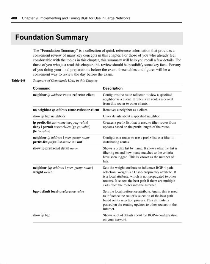
488 Chapter 9: Implementing and Tuning BGP for Use in Large Networks
Foundation Summary
The “Foundation Summary” is a collection of quick reference information that provides a convenient review of many key concepts in this chapter. For those of you who already feel comfortable with the topics in this chapter, this summary will help you recall a few details. For those of you who just read this chapter, this review should help solidify some key facts. For any of you doing your final preparations before the exam, these tables and figures will be a convenient way to review the day before the exam.
Table 9-9 Summary of Commands Used in this Chapter
Command Description
neighbor ip-address route-reflector-client Configures the route reflector to view a specified neighbor as a client. It reflects all routes received from this router to other clients.
no neighbor ip-address route-reflector-client Removes a neighbor as a client.
show ip bgp neighbors Gives details about a specified neighbor.
ip prefix-list list-name [seq seq-value] deny | permit network/len [ge ge-value] [le le-value]
Creates a prefix list that is used to filter routes from updates based on the prefix length of the route.
neighbor ip address | peer-group-name prefix-list prefix-list-name in | out
Configures a router to use a prefix list as a filter in distributing routes.
show ip prefix-list detail name Shows a prefix list by name. It shows what the list is filtering on and how many matches to the criteria have seen logged. This is known as the number of hits.
neighbor {ip-address | peer-group-name} weight weight
Sets the weight attribute to influence BGP-4 path selection. Weight is a Cisco-proprietary attribute. It is a local attribute, which is not propagated to other routers. It selects the best path if there are multiple exits from the router into the Internet.
bgp default local-preference value Sets the local preference attribute. Again, this is used to influence the router’s selection of the best path based on its selection process. This attribute is passed on the routing updates to other routers in the Internet.
show ip bgp Shows a lot of details about the BGP-4 configuration on your network.
chpt_01.book Page 488 Thursday, December 21, 2000 6:22 PM
Route Reflectors 489
Route ReflectorsThe benefits of route reflectors include the following:
• The capability to scale the network, given the other characteristics
• A strong hierarchical design
• A reduction of traffic on the network
• A reduction in the memory and CPU to maintain TCP sessions
• Faster convergence because synchronization is not needed
• Faster convergence and a simpler network because two routing protocols are implemented:
— IBGP-4 for external routing information traversing the autonomous system
— IGP for routes internal to the autonomous system
Characteristics of route reflectors are as follows:
• A route reflector is a router that forwards updates to its clients. When a client sends an update to the route reflector, it is forwarded or reflected to the other clients.
• The route reflector is the only router that is configured or that has the remotest idea that it is anything other than a peer.
• A client is a router that receives updates from a route reflector.
• Both a route reflector and a client, therefore, form a unit that shares information. This unit is called a cluster.
• The autonomous system is divided into clusters and is configured. There must be at least one route reflector per cluster; otherwise, the clients will not get the updates reflected to them.
• The route reflector and the client no longer require a full peer relationship because the route reflector forwards updates from other clients.
• In all probability, a route reflector is connected to peers for whom it is not forwarding routes. These are regular neighbors or peers but, from the route reflector’s view, they are nonclients.
• Nonclients must be fully meshed with the route reflector.
• The route reflector connects to other route reflectors. These route reflectors need to be fully meshed because the old rule of not propagating routes that are not defined in the network command is now operational. This is to ensure that the IBGP-4 routing tables are complete.
chpt_01.book Page 489 Thursday, December 21, 2000 6:22 PM
490 Chapter 9: Implementing and Tuning BGP for Use in Large Networks
• When the route reflector forwards an update, the Originator-ID attribute is set. This is the BGP-4 router ID of the router that originated the path. The purpose of this attribute is not to award honors to the originating router, but so that, if this router receives the update, it will see its own ID and will ignore the packet. This prevents the possibility of routing loops.
• If there are multiple route reflectors in the cluster, to provide redundancy, then the originating router is identified by the Cluster-ID attribute. This serves the same purpose as the Originator-ID in preventing routing loops.
The rules by which route reflectors propagate updates are as follows:
• If a route reflector receives multiple paths to the same destination, it chooses the best path.
• If the route is received from a client, then the route reflector reflects/forwards the update to clients and nonclients, except for the originator of the route.
• If the route is received from a nonclient, then the route reflector reflects the update only to clients.
• If the route is received from EBGP-4, then the route reflector reflects it to all nonclients as well as clients.
Prefix ListsWhether a prefix is permitted or denied is based upon the following rules:
• If a route is permitted, the route is used.
• If a route is denied, the route is not used.
• If the prefix list is empty, all prefixes are permitted.
• At the bottom of every prefix list is an implicit deny all. Thus, if given prefix does not match any entries of a prefix list, it is denied.
• When multiple entries of a prefix list match a given prefix, the entry with the smallest sequence number is used.
• The router begins the search at the top of the prefix list, with the sequence number 1. When a match is made, the search stops. Processing time will be reduced if the most common matches or denies are near the top of the list. This will prevent having to process criteria that are seldom met every time a route is examined.
• Sequence numbers are generated by default. To configure the sequence numbers manually, use the seq seq-value argument of the ip prefix-list command.
• A sequence number does not need to be specified when removing a configuration entry.
chpt_01.book Page 490 Thursday, December 21, 2000 6:22 PM
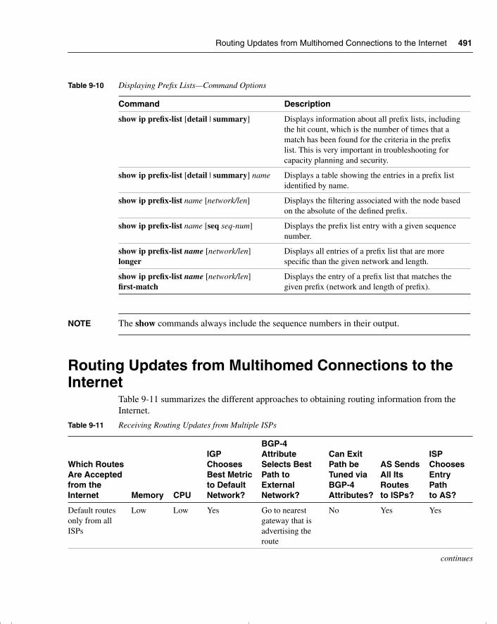
Routing Updates from Multihomed Connections to the Internet 491
NOTE The show commands always include the sequence numbers in their output.
Routing Updates from Multihomed Connections to the Internet
Table 9-11 summarizes the different approaches to obtaining routing information from the Internet.
Table 9-10 Displaying Prefix Lists—Command Options
Command Description
show ip prefix-list [detail | summary] Displays information about all prefix lists, including the hit count, which is the number of times that a match has been found for the criteria in the prefix list. This is very important in troubleshooting for capacity planning and security.
show ip prefix-list [detail | summary] name Displays a table showing the entries in a prefix list identified by name.
show ip prefix-list name [network/len] Displays the filtering associated with the node based on the absolute of the defined prefix.
show ip prefix-list name [seq seq-num] Displays the prefix list entry with a given sequence number.
show ip prefix-list name [network/len] longer
Displays all entries of a prefix list that are more specific than the given network and length.
show ip prefix-list name [network/len] first-match
Displays the entry of a prefix list that matches the given prefix (network and length of prefix).
Table 9-11 Receiving Routing Updates from Multiple ISPs
Which RoutesAre Acceptedfrom the Internet Memory CPU
IGP ChoosesBest Metric to DefaultNetwork?
BGP-4 AttributeSelects Best Path to ExternalNetwork?
Can Exit Path be Tuned viaBGP-4Attributes?
AS Sends All Its Routes to ISPs?
ISPChoosesEntry Pathto AS?
Default routes only from all ISPs
Low Low Yes Go to nearest gateway that is advertising the route
No Yes Yes
continues
chpt_01.book Page 491 Thursday, December 21, 2000 6:22 PM
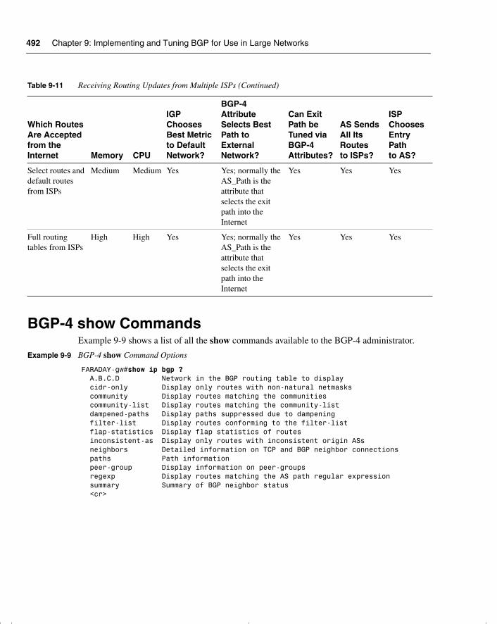
492 Chapter 9: Implementing and Tuning BGP for Use in Large Networks
BGP-4 show CommandsExample 9-9 shows a list of all the show commands available to the BGP-4 administrator.
Select routes and default routes from ISPs
Medium Medium Yes Yes; normally the AS_Path is the attribute that selects the exit path into the Internet
Yes Yes Yes
Full routing tables from ISPs
High High Yes Yes; normally the AS_Path is the attribute that selects the exit path into the Internet
Yes Yes Yes
Example 9-9 BGP-4 show Command Options
FARADAY-gw#show ip bgp ? A.B.C.D Network in the BGP routing table to display cidr-only Display only routes with non-natural netmasks community Display routes matching the communities community-list Display routes matching the community-list dampened-paths Display paths suppressed due to dampening filter-list Display routes conforming to the filter-list flap-statistics Display flap statistics of routes inconsistent-as Display only routes with inconsistent origin ASs neighbors Detailed information on TCP and BGP neighbor connections paths Path information peer-group Display information on peer-groups regexp Display routes matching the AS path regular expression summary Summary of BGP neighbor status <cr>
Table 9-11 Receiving Routing Updates from Multiple ISPs (Continued)
Which RoutesAre Acceptedfrom the Internet Memory CPU
IGP ChoosesBest Metric to DefaultNetwork?
BGP-4 AttributeSelects Best Path to ExternalNetwork?
Can Exit Path be Tuned viaBGP-4Attributes?
AS Sends All Its Routes to ISPs?
ISPChoosesEntry Pathto AS?
chpt_01.book Page 492 Thursday, December 21, 2000 6:22 PM
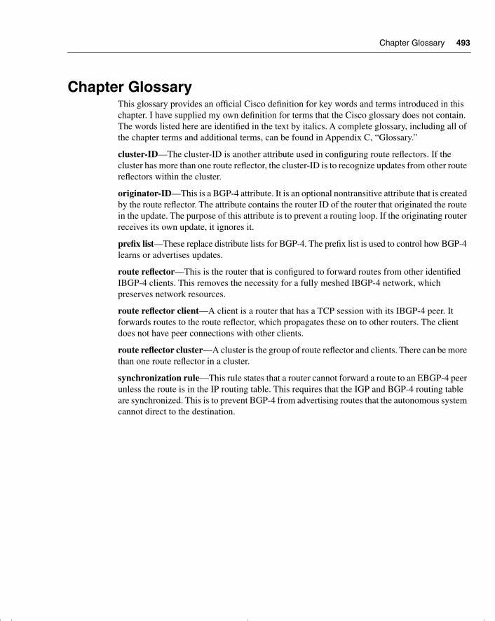
Chapter Glossary 493
Chapter GlossaryThis glossary provides an official Cisco definition for key words and terms introduced in this chapter. I have supplied my own definition for terms that the Cisco glossary does not contain. The words listed here are identified in the text by italics. A complete glossary, including all of the chapter terms and additional terms, can be found in Appendix C, “Glossary.”
cluster-ID—The cluster-ID is another attribute used in configuring route reflectors. If the cluster has more than one route reflector, the cluster-ID is to recognize updates from other route reflectors within the cluster.
originator-ID—This is a BGP-4 attribute. It is an optional nontransitive attribute that is created by the route reflector. The attribute contains the router ID of the router that originated the route in the update. The purpose of this attribute is to prevent a routing loop. If the originating router receives its own update, it ignores it.
prefix list—These replace distribute lists for BGP-4. The prefix list is used to control how BGP-4 learns or advertises updates.
route reflector—This is the router that is configured to forward routes from other identified IBGP-4 clients. This removes the necessity for a fully meshed IBGP-4 network, which preserves network resources.
route reflector client—A client is a router that has a TCP session with its IBGP-4 peer. It forwards routes to the route reflector, which propagates these on to other routers. The client does not have peer connections with other clients.
route reflector cluster—A cluster is the group of route reflector and clients. There can be more than one route reflector in a cluster.
synchronization rule—This rule states that a router cannot forward a route to an EBGP-4 peer unless the route is in the IP routing table. This requires that the IGP and BGP-4 routing table are synchronized. This is to prevent BGP-4 from advertising routes that the autonomous system cannot direct to the destination.
chpt_01.book Page 493 Thursday, December 21, 2000 6:22 PM
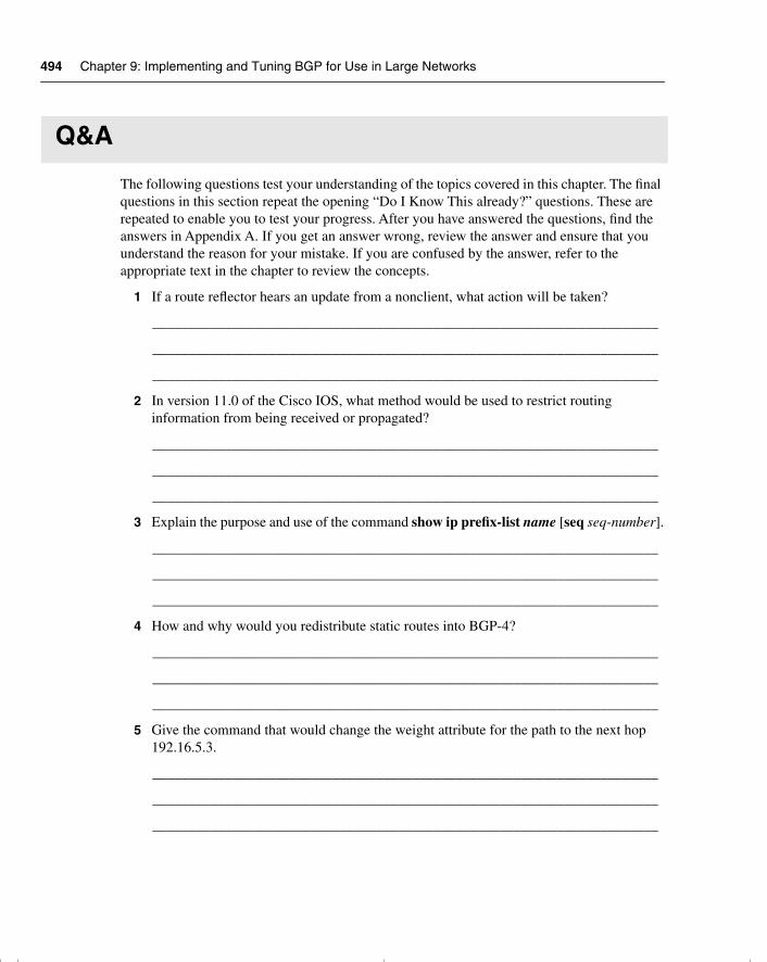
494 Chapter 9: Implementing and Tuning BGP for Use in Large Networks
Q&A
The following questions test your understanding of the topics covered in this chapter. The final questions in this section repeat the opening “Do I Know This already?” questions. These are repeated to enable you to test your progress. After you have answered the questions, find the answers in Appendix A. If you get an answer wrong, review the answer and ensure that you understand the reason for your mistake. If you are confused by the answer, refer to the appropriate text in the chapter to review the concepts.
1 If a route reflector hears an update from a nonclient, what action will be taken?
______________________________________________________________________
______________________________________________________________________
______________________________________________________________________
2 In version 11.0 of the Cisco IOS, what method would be used to restrict routing information from being received or propagated?
______________________________________________________________________
______________________________________________________________________
______________________________________________________________________
3 Explain the purpose and use of the command show ip prefix-list name [seq seq-number].
______________________________________________________________________
______________________________________________________________________
______________________________________________________________________
4 How and why would you redistribute static routes into BGP-4?
______________________________________________________________________
______________________________________________________________________
______________________________________________________________________
5 Give the command that would change the weight attribute for the path to the next hop 192.16.5.3.
______________________________________________________________________
______________________________________________________________________
______________________________________________________________________
chpt_01.book Page 494 Thursday, December 21, 2000 6:22 PM
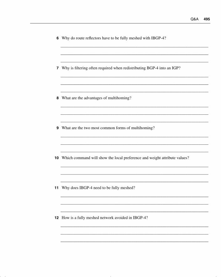
Q&A 495
6 Why do route reflectors have to be fully meshed with IBGP-4?
_______________________________________________________________________
_______________________________________________________________________
_______________________________________________________________________
7 Why is filtering often required when redistributing BGP-4 into an IGP?
_______________________________________________________________________
_______________________________________________________________________
_______________________________________________________________________
8 What are the advantages of multihoming?
_______________________________________________________________________
_______________________________________________________________________
_______________________________________________________________________
9 What are the two most common forms of multihoming?
_______________________________________________________________________
_______________________________________________________________________
_______________________________________________________________________
10 Which command will show the local preference and weight attribute values?
_______________________________________________________________________
_______________________________________________________________________
_______________________________________________________________________
11 Why does IBGP-4 need to be fully meshed?
_______________________________________________________________________
_______________________________________________________________________
_______________________________________________________________________
12 How is a fully meshed network avoided in IBGP-4?
_______________________________________________________________________
_______________________________________________________________________
_______________________________________________________________________
chpt_01.book Page 495 Thursday, December 21, 2000 6:22 PM
496 Chapter 9: Implementing and Tuning BGP for Use in Large Networks
13 What is the formula to determine the number of sessions that are needed in a fully meshed BGP-4 network?
______________________________________________________________________
______________________________________________________________________
______________________________________________________________________
14 Why does a fully meshed network in IBGP-4 cause problems?
______________________________________________________________________
______________________________________________________________________
______________________________________________________________________
15 State two benefits to using route reflectors.
______________________________________________________________________
______________________________________________________________________
______________________________________________________________________
16 Can the next-hop-self option be used between EBGP-4 peers?
______________________________________________________________________
______________________________________________________________________
______________________________________________________________________
17 Explain the difference between a cluster-ID and an originator-ID.
______________________________________________________________________
______________________________________________________________________
______________________________________________________________________
18 State two advantages in using prefix lists over access lists.
______________________________________________________________________
______________________________________________________________________
______________________________________________________________________
19 If the ISP has provided a default route, how will the router within the autonomous system select the exit path in a multihomed environment?
______________________________________________________________________
______________________________________________________________________
______________________________________________________________________
chpt_01.book Page 496 Thursday, December 21, 2000 6:22 PM
Q&A 497
20 What is a disadvantage of an autonomous system receiving full routing updates from all providers?
_______________________________________________________________________
_______________________________________________________________________
_______________________________________________________________________
21 What is the danger of redistributing BGP-4 into the IGP?
_______________________________________________________________________
_______________________________________________________________________
_______________________________________________________________________
22 What are the advantages of a fully meshed IBGP-4 network?
_______________________________________________________________________
_______________________________________________________________________
_______________________________________________________________________
23 In configuring a route reflector, how is the client configured?
_______________________________________________________________________
_______________________________________________________________________
_______________________________________________________________________
24 What command is used to display the route reflector clients?
_______________________________________________________________________
_______________________________________________________________________
_______________________________________________________________________
25 What commands are used to display the BGP-4 router ID that identifies the router that is sending the updates and peering with its neighbor?
_______________________________________________________________________
_______________________________________________________________________
_______________________________________________________________________
26 Which command is used to display the AS_Path?
_______________________________________________________________________
_______________________________________________________________________
_______________________________________________________________________
chpt_01.book Page 497 Thursday, December 21, 2000 6:22 PM
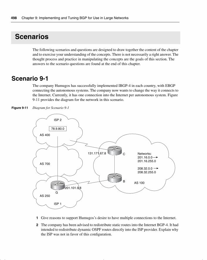
498 Chapter 9: Implementing and Tuning BGP for Use in Large Networks
Scenarios
The following scenarios and questions are designed to draw together the content of the chapter and to exercise your understanding of the concepts. There is not necessarily a right answer. The thought process and practice in manipulating the concepts are the goals of this section. The answers to the scenario questions are found at the end of this chapter.
Scenario 9-1The company Humugos has successfully implemented IBGP-4 in each country, with EBGP connecting the autonomous systems. The company now wants to change the way it connects to the Internet. Currently, it has one connection into the Internet per autonomous system. Figure 9-11 provides the diagram for the network in this scenario.
Figure 9-11 Diagram for Scenario 9-1
1 Give reasons to support Humugos’s desire to have multiple connections to the Internet.
2 The company has been advised to redistribute static routes into the Internet BGP-4. It had intended to redistribute dynamic OSPF routes directly into the ISP provider. Explain why the ISP was not in favor of this configuration.
AS 100
AS 250
ISP 1
AS 400
AS 700
ISP 2
78.9.80.0
G
C
B
131.171.67.8
201.101.9.8
Networks:201.16.0.0201.16.255.0
208.32.0.0208.32.255.0
chpt_01.book Page 498 Thursday, December 21, 2000 6:22 PM
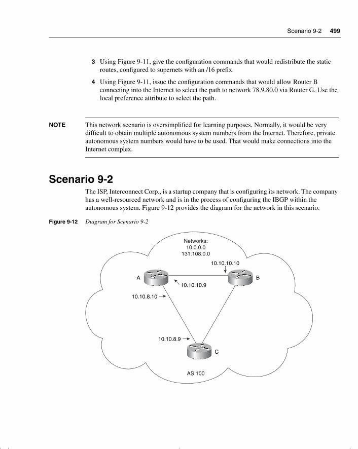
Scenario 9-2 499
3 Using Figure 9-11, give the configuration commands that would redistribute the static routes, configured to supernets with an /16 prefix.
4 Using Figure 9-11, issue the configuration commands that would allow Router B connecting into the Internet to select the path to network 78.9.80.0 via Router G. Use the local preference attribute to select the path.
NOTE This network scenario is oversimplified for learning purposes. Normally, it would be very difficult to obtain multiple autonomous system numbers from the Internet. Therefore, private autonomous system numbers would have to be used. That would make connections into the Internet complex.
Scenario 9-2The ISP, Interconnect Corp., is a startup company that is configuring its network. The company has a well-resourced network and is in the process of configuring the IBGP within the autonomous system. Figure 9-12 provides the diagram for the network in this scenario.
Figure 9-12 Diagram for Scenario 9-2
A
C
B
Networks:10.0.0.0
131.108.0.0
AS 100
10.10.10.10
10.10.8.10
10.10.8.9
10.10.10.9
chpt_01.book Page 499 Thursday, December 21, 2000 6:22 PM
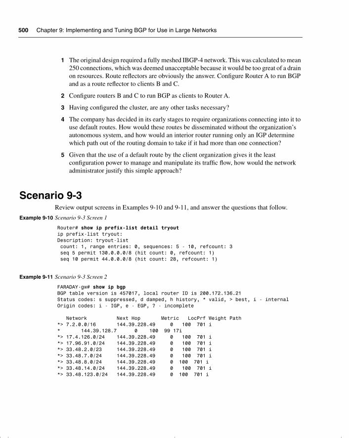
500 Chapter 9: Implementing and Tuning BGP for Use in Large Networks
1 The original design required a fully meshed IBGP-4 network. This was calculated to mean 250 connections, which was deemed unacceptable because it would be too great of a drain on resources. Route reflectors are obviously the answer. Configure Router A to run BGP and as a route reflector to clients B and C.
2 Configure routers B and C to run BGP as clients to Router A.
3 Having configured the cluster, are any other tasks necessary?
4 The company has decided in its early stages to require organizations connecting into it to use default routes. How would these routes be disseminated without the organization’s autonomous system, and how would an interior router running only an IGP determine which path out of the routing domain to take if it had more than one connection?
5 Given that the use of a default route by the client organization gives it the least configuration power to manage and manipulate its traffic flow, how would the network administrator justify this simple approach?
Scenario 9-3Review output screens in Examples 9-10 and 9-11, and answer the questions that follow.
Example 9-10 Scenario 9-3 Screen 1
Router# show ip prefix-list detail tryoutip prefix-list tryout:Description: tryout-list count: 1, range entries: 0, sequences: 5 - 10, refcount: 3 seq 5 permit 130.0.0.0/8 (hit count: 0, refcount: 1) seq 10 permit 44.0.0.0/8 (hit count: 28, refcount: 1)
Example 9-11 Scenario 9-3 Screen 2
FARADAY-gw# show ip bgpBGP table version is 457017, local router ID is 200.172.136.21Status codes: s suppressed, d damped, h history, * valid, > best, i - internalOrigin codes: i - IGP, e - EGP, ? - incomplete
Network Next Hop Metric LocPrf Weight Path*> 7.2.0.0/16 144.39.228.49 0 100 701 i* 144.39.128.7 0 100 99 17i*> 17.4.126.0/24 144.39.228.49 0 100 701 i*> 17.96.91.0/24 144.39.228.49 0 100 701 i*> 33.48.2.0/23 144.39.228.49 0 100 701 i*> 33.48.7.0/24 144.39.228.49 0 100 701 i*> 33.48.8.0/24 144.39.228.49 0 100 701 i*> 33.48.14.0/24 144.39.228.49 0 100 701 i*> 33.48.123.0/24 144.39.228.49 0 100 701 i
chpt_01.book Page 500 Thursday, December 21, 2000 6:22 PM
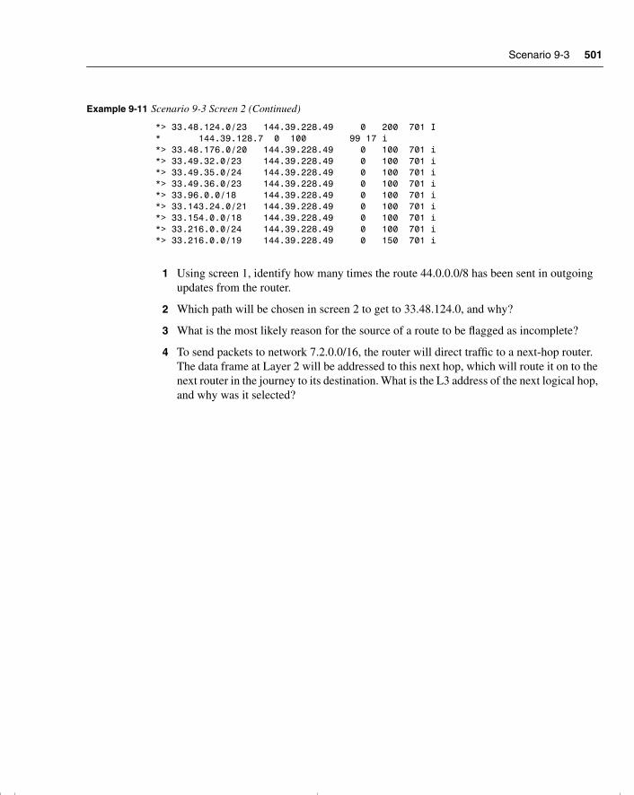
Scenario 9-3 501
1 Using screen 1, identify how many times the route 44.0.0.0/8 has been sent in outgoing updates from the router.
2 Which path will be chosen in screen 2 to get to 33.48.124.0, and why?
3 What is the most likely reason for the source of a route to be flagged as incomplete?
4 To send packets to network 7.2.0.0/16, the router will direct traffic to a next-hop router. The data frame at Layer 2 will be addressed to this next hop, which will route it on to the next router in the journey to its destination. What is the L3 address of the next logical hop, and why was it selected?
*> 33.48.124.0/23 144.39.228.49 0 200 701 I* 144.39.128.7 0 100 99 17 i*> 33.48.176.0/20 144.39.228.49 0 100 701 i*> 33.49.32.0/23 144.39.228.49 0 100 701 i*> 33.49.35.0/24 144.39.228.49 0 100 701 i*> 33.49.36.0/23 144.39.228.49 0 100 701 i*> 33.96.0.0/18 144.39.228.49 0 100 701 i*> 33.143.24.0/21 144.39.228.49 0 100 701 i*> 33.154.0.0/18 144.39.228.49 0 100 701 i*> 33.216.0.0/24 144.39.228.49 0 100 701 i*> 33.216.0.0/19 144.39.228.49 0 150 701 i
Example 9-11 Scenario 9-3 Screen 2 (Continued)
chpt_01.book Page 501 Thursday, December 21, 2000 6:22 PM
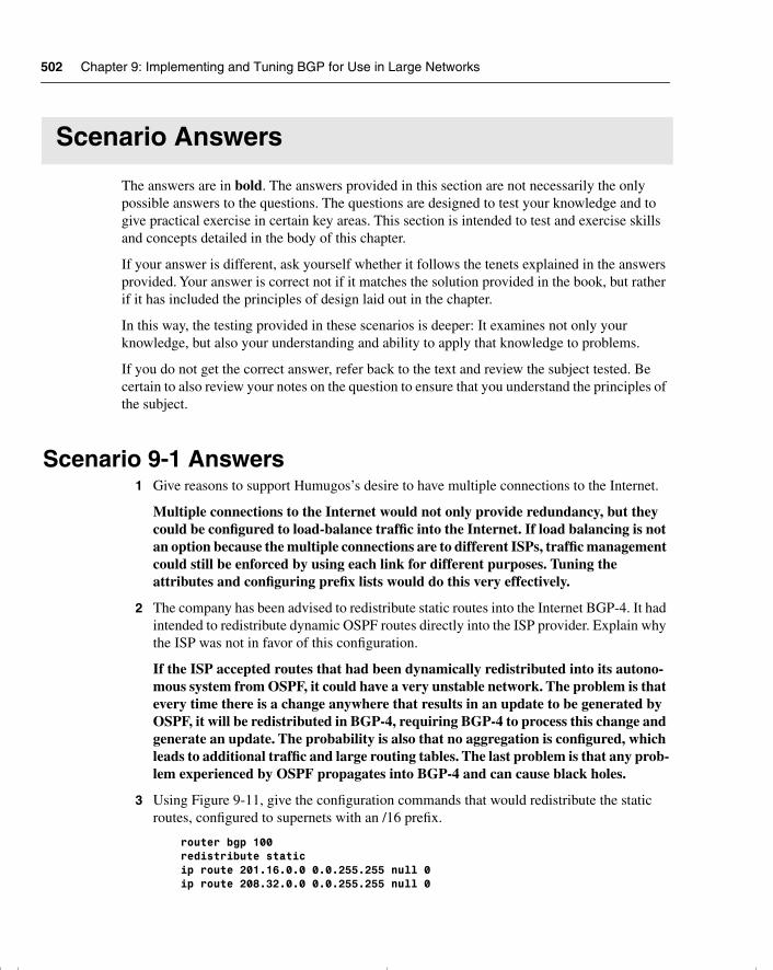
502 Chapter 9: Implementing and Tuning BGP for Use in Large Networks
Scenario Answers
The answers are in bold. The answers provided in this section are not necessarily the only possible answers to the questions. The questions are designed to test your knowledge and to give practical exercise in certain key areas. This section is intended to test and exercise skills and concepts detailed in the body of this chapter.
If your answer is different, ask yourself whether it follows the tenets explained in the answers provided. Your answer is correct not if it matches the solution provided in the book, but rather if it has included the principles of design laid out in the chapter.
In this way, the testing provided in these scenarios is deeper: It examines not only your knowledge, but also your understanding and ability to apply that knowledge to problems.
If you do not get the correct answer, refer back to the text and review the subject tested. Be certain to also review your notes on the question to ensure that you understand the principles of the subject.
Scenario 9-1 Answers1 Give reasons to support Humugos’s desire to have multiple connections to the Internet.
Multiple connections to the Internet would not only provide redundancy, but they could be configured to load-balance traffic into the Internet. If load balancing is not an option because the multiple connections are to different ISPs, traffic management could still be enforced by using each link for different purposes. Tuning the attributes and configuring prefix lists would do this very effectively.
2 The company has been advised to redistribute static routes into the Internet BGP-4. It had intended to redistribute dynamic OSPF routes directly into the ISP provider. Explain why the ISP was not in favor of this configuration.
If the ISP accepted routes that had been dynamically redistributed into its autono-mous system from OSPF, it could have a very unstable network. The problem is that every time there is a change anywhere that results in an update to be generated by OSPF, it will be redistributed in BGP-4, requiring BGP-4 to process this change and generate an update. The probability is also that no aggregation is configured, which leads to additional traffic and large routing tables. The last problem is that any prob-lem experienced by OSPF propagates into BGP-4 and can cause black holes.
3 Using Figure 9-11, give the configuration commands that would redistribute the static routes, configured to supernets with an /16 prefix.
router bgp 100 redistribute static ip route 201.16.0.0 0.0.255.255 null 0 ip route 208.32.0.0 0.0.255.255 null 0
chpt_01.book Page 502 Thursday, December 21, 2000 6:22 PM
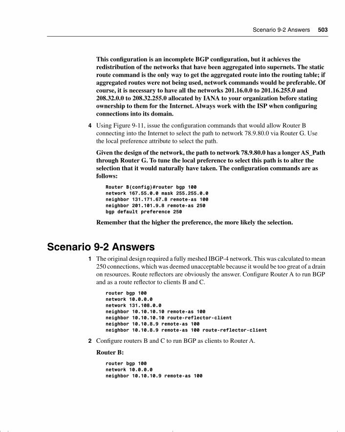
Scenario 9-2 Answers 503
This configuration is an incomplete BGP configuration, but it achieves the redistribution of the networks that have been aggregated into supernets. The static route command is the only way to get the aggregated route into the routing table; if aggregated routes were not being used, network commands would be preferable. Of course, it is necessary to have all the networks 201.16.0.0 to 201.16.255.0 and 208.32.0.0 to 208.32.255.0 allocated by IANA to your organization before stating ownership to them for the Internet. Always work with the ISP when configuring connections into its domain.
4 Using Figure 9-11, issue the configuration commands that would allow Router B connecting into the Internet to select the path to network 78.9.80.0 via Router G. Use the local preference attribute to select the path.
Given the design of the network, the path to network 78.9.80.0 has a longer AS_Path through Router G. To tune the local preference to select this path is to alter the selection that it would naturally have taken. The configuration commands are as follows:
Router B(config)#router bgp 100network 167.55.0.0 mask 255.255.0.0neighbor 131.171.67.8 remote-as 100neighbor 201.101.9.8 remote-as 250bgp default preference 250
Remember that the higher the preference, the more likely the selection.
Scenario 9-2 Answers1 The original design required a fully meshed IBGP-4 network. This was calculated to mean
250 connections, which was deemed unacceptable because it would be too great of a drain on resources. Route reflectors are obviously the answer. Configure Router A to run BGP and as a route reflector to clients B and C.
router bgp 100network 10.0.0.0network 131.108.0.0neighbor 10.10.10.10 remote-as 100neighbor 10.10.10.10 route-reflector-clientneighbor 10.10.8.9 remote-as 100neighbor 10.10.8.9 remote-as 100 route-reflector-client
2 Configure routers B and C to run BGP as clients to Router A.
Router B:
router bgp 100network 10.0.0.0neighbor 10.10.10.9 remote-as 100
chpt_01.book Page 503 Thursday, December 21, 2000 6:22 PM
504 Chapter 9: Implementing and Tuning BGP for Use in Large Networks
Router C:
router bgp 100network 10.0.0.0neighbor 10.10.8.10 remote-as 100
3 Having configured the cluster, are any other tasks necessary?
Given that the route reflector is now forwarding the routes between B and C, the link between these routers is no longer necessary, and the BGP-4 link between them should be broken. This simply requires the removal of the neighbor statements that create the link on both routers B and C.
4 The company has decided in its early stages to require organizations connecting into them to use default routes. How would these routes be disseminated without the organization’s autonomous system, and how would an interior router running only an IGP determine which path out of the routing domain to take if it had more than one connection?
The routers in the client organization do not need to run BGP-4. They simply need to configure a default route and propagate this into the routing domain, in accordance with the interior routing protocol that is being run.
If the autonomous system were multihomed into the Internet, there would be more than one default route propagated throughout the system. Any router within the autonomous system would determine the best path to the outside world by comparing the routing protocol metrics between the default routes. Thus, RIP would select the lowest hop count, EIGRP the lowest combination of bandwidth and delay, and OSPF the lowest cost.
5 Given that the use of a default route by the client organization gives its the least configuration power to manage and manipulate its traffic flow, how would the network administrator justify this simple approach?
The default route, while giving the least control over the connection to the Internet, is very robust in that it has no working parts to fail. Therefore, it requires very little CPU or memory. The lack of redistribution eliminates the possibility of routing loops, and no routing protocol running over the physical link to the Internet frees up bandwidth for data.
Scenario 9-3 Answers1 Using screen 1, identify how many times the route 44.0.0.0/8 has been sent in outgoing
updates from the router?
The prefix list tryout has 28 hits logged for the network 44.0.0.0/8. This means that 28 updates have been sent with the network 44.0.0.0 from the router to its neighbors.
chpt_01.book Page 504 Thursday, December 21, 2000 6:22 PM
Scenario 9-3 Answers 505
2 Which path will be chosen in screen 2 to get to 33.48.124.0, and why?
The path using 144.39.228.49 as the next hop will be used even though it has the longer AS_Path. The local preference is set to 200. Because the local preference is looked at before the AS_Path, this path will be selected.
3 What is the most likely reason for the source of a route to be flagged as incomplete?
The route was probably redistributed into BGP-4, and it therefore cannot identify as much information as if it were received as a routing update with attributes attached.
4 To send packets to network 7.2.0.0/16, the router will direct traffic to a next-hop router. The data frame at Layer 2 will be addressed to this next hop, which will route it on to the next router in the journey to its destination. What is the L3 address of the next logical hop, and why was it selected?
The next logical hop for the route 7.2.0.0/16 is 144.39.228.49. This address was selected because it is the next hop in the best path to the destination. BGP-4 determined the best path based on AS_PATH. The alternate route has to journey through two autonomous systems to find the destination network, so this path has a more direct route. Because neither the weight attribute nor the local preference attribute has been tuned, the AS_Path is the determining attribute.
chpt_01.book Page 505 Thursday, December 21, 2000 6:22 PM

This chapter covers the following topics that you will need to master to pass the CCNP/CCDP Routing exam:
• Selecting and configuring the different ways to control route update traffic.
• Configuring route redistribution in a network that does not have redundant paths between dissimilar routing processes.
• Configuring route redistribution in a network that has redundant paths between dissimilar routing processes.
• Resolving path selection problems that result in a redistributed network.
• Verifying route redistribution.
• Configuring policy based routing using route maps.
• The Cisco commands for configuring passive interfaces, static routes, default routes, administrative distance, default metrics, redistribution, distribution lists, and routes maps. Cisco commands for reviewing and testing the configuration are also covered.
chpt_01.book Page 506 Thursday, December 21, 2000 6:22 PM
C H A P T E R 10
Controlling Routing Updates Across the Network
The topics in this chapter deal with the traffic generated by the routing updates in terms of both the network resources that they use and the information contained within them. This covers two different but related areas. The network overhead involved in routing updates has already been dealt with in other chapters, and it keeps recurring as a theme because all network traffic directly influences the network’s capability to scale or grow. The issue is very complex and deals with the design of the network and configuring around that design.
The information propagated through the network is complex when dealing with one routing protocol. When multiple protocols have to share information so that the larger network can see every route available within the routing domain, life can become very confused. At this point, the information flow must be controlled and managed very closely.
This chapter deals with these issues, focusing mainly on the configuration of redistribution and route filtering. This is founded in a conceptual explanation and a brief consideration of the design issues that may affect the configuration. The Routing exam will probably concentrate on the configuration commands because the other areas are very esoteric and are very dependent on the individual design of any given network.
The BSCN course devotes 16 percent of its material to redistribution and filtering, which is more than any other single subject is allocated. The majority of these BSCN pages are concerned with configuration, so it is fair to conclude that the exam may concentrate on this area.
One of the reasons that the course is concerned with redistribution is because the fundamentals of filtering comprise many of the calls to the telephone support group. In addition, the Routing exam is one of the steps to becoming a CCNP, a highly coveted title that tells the world that you have competency in the management of large networks. Many of these large networks have some level of redistribution, and nearly all contain route filtering in some form.
How to Best Use This ChapterBy taking the following steps, you can make better use of your study time:
• Keep your notes and the answers for all your work with this book in one place, for easy reference.
chpt_01.book Page 507 Thursday, December 21, 2000 6:22 PM

508 Chapter 10: Controlling Routing Updates Across the Network
• When you take a quiz, write down your answers. Studies show that retention significantly increases by writing down facts and concepts, even if you never look at the information again.
• Use the diagram in Figure 10-1 to guide you to the next step.
Figure 10-1 How to Use This Chapter
“Do I Know This Already?” QuizThe purpose of the “Do I Know This Already?” quiz is to help you decide what parts of this chapter to use. If you already intend to read the entire chapter, you do not necessarily need to answer these questions now.
This 16-question quiz helps you determine how to spend your limited study time. The quiz is sectioned into four smaller four-question “quizlets,” which correspond to four major topics in the chapter. Figure 10-1 outlines suggestions on how to spend your time in this chapter. Use Table 10-1 to record your scores.
Lowscore
Low quizletscore
Mediumscore
High score,want more
review
Highscore
"Do I Know This Already?" quiz
ReadFoundation
Topics
Read relatedFoundation Topics
subsection
ReadFoundationSummary
Q&A Scenarios
Go to nextchapter
If you skip to the Foundation Summary, Q&A, and Scenarios sections and havetrouble with the material there, you should go to the Foundation Topics section.
chpt_01.book Page 508 Thursday, December 21, 2000 6:22 PM
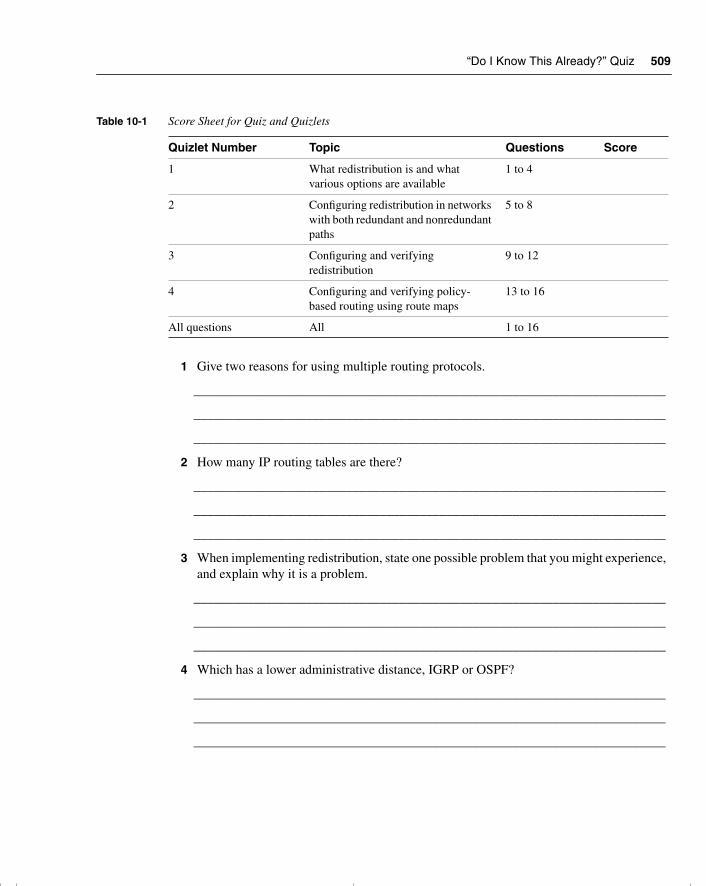
“Do I Know This Already?” Quiz 509
1 Give two reasons for using multiple routing protocols.
_______________________________________________________________________
_______________________________________________________________________
_______________________________________________________________________
2 How many IP routing tables are there?
_______________________________________________________________________
_______________________________________________________________________
_______________________________________________________________________
3 When implementing redistribution, state one possible problem that you might experience, and explain why it is a problem.
_______________________________________________________________________
_______________________________________________________________________
_______________________________________________________________________
4 Which has a lower administrative distance, IGRP or OSPF?
_______________________________________________________________________
_______________________________________________________________________
_______________________________________________________________________
Table 10-1 Score Sheet for Quiz and Quizlets
Quizlet Number Topic Questions Score
1 What redistribution is and what various options are available
1 to 4
2 Configuring redistribution in networks with both redundant and nonredundant paths
5 to 8
3 Configuring and verifying redistribution
9 to 12
4 Configuring and verifying policy-based routing using route maps
13 to 16
All questions All 1 to 16
chpt_01.book Page 509 Thursday, December 21, 2000 6:22 PM
510 Chapter 10: Controlling Routing Updates Across the Network
5 What command is used to configure an outbound route filter?
______________________________________________________________________
______________________________________________________________________
______________________________________________________________________
6 What is a passive interface?
______________________________________________________________________
______________________________________________________________________
______________________________________________________________________
7 What is the purpose of administrative distance?
______________________________________________________________________
______________________________________________________________________
______________________________________________________________________
8 What is the concern of redistributing into a redundant network?
______________________________________________________________________
______________________________________________________________________
______________________________________________________________________
9 What is a default network?
______________________________________________________________________
______________________________________________________________________
______________________________________________________________________
10 Why is it necessary to configure a default metric when redistributing between routing protocols?
______________________________________________________________________
______________________________________________________________________
______________________________________________________________________
11 Which command is used to modify the administrative distance of a route?
______________________________________________________________________
______________________________________________________________________
______________________________________________________________________
chpt_01.book Page 510 Thursday, December 21, 2000 6:22 PM
“Do I Know This Already?” Quiz 511
12 What is the difference in processing for an inbound and an outbound route filter?
_______________________________________________________________________
_______________________________________________________________________
_______________________________________________________________________
13 State two benefits of using policy-based routing.
_______________________________________________________________________
_______________________________________________________________________
_______________________________________________________________________
14 How are matching routes modified in a route map?
_______________________________________________________________________
_______________________________________________________________________
_______________________________________________________________________
15 Explain the command set ip default-next-hop [ip-address...ip-address].
_______________________________________________________________________
_______________________________________________________________________
_______________________________________________________________________
16 Which command displays route maps that are configured on interfaces?
_______________________________________________________________________
_______________________________________________________________________
_______________________________________________________________________
The answers to this quiz are found in Appendix A, “Answers to Quiz Questions.” The suggested choices for your next step are as follows:
• 2 or less on any quizlet—Review the appropriate sections of the “Foundation Topics” portion of this chapter, based on Table 10-1. Then move on to the “Foundation Summary” section, the “Q&A” section, and the “Scenarios” at the end of the chapter.
• 8 or less overall score—Read the entire chapter. This includes the “Foundation Topics” and “Foundation Summary” sections, the “Q&A” section, and the “Scenarios” at the end of the chapter.
chpt_01.book Page 511 Thursday, December 21, 2000 6:22 PM
512 Chapter 10: Controlling Routing Updates Across the Network
• 9 to 12 overall score—Begin with the “Foundation Summary” section, and then go to the “Q&A” section and the “Scenarios” at the end of the chapter. If you have trouble with these exercises, read the appropriate sections in “Foundation Topics.”
• 13 or more overall score—If you want more review on these topics, skip to the “Foundation Summary” section, and then go to the “Q&A” section and the “Scenarios” at the end of the chapter. Otherwise, move to the next chapter.
chpt_01.book Page 512 Thursday, December 21, 2000 6:22 PM
Redistribution Between Routing Protocols 513
Foundation Topics
The following section examines the implications of using redistribution.
Introduction: Controlling the Routing Updates Using Redistribution and Filtering
Redistribution is often necessary within a network, if only as a transitional implementation. Nonetheless, it should not be thought of as a quick and easy solution. Although route redistribution is often a lifesaver for your network, is fraught with complexity. Understanding the operation of the processes that you have implemented and how this influences your network is crucial. This chapter deals with the main topics dealing with the implementation of the network.
Case StudyDuddleduddle is a large hospital with several sites in the city. Although the sites connect to a centralized patient and administration database, the hospital has fought for local autonomy based on the specialization of the site and the fact that it is its own business unit. An IT group manages the central administration and oversees the other sites. The chief information officer (CIO) who ran this group and the overall network has left because of political wrangling. The new CIO, recently appointed, is attempting to sort out the mess.
This new CIO has the agreement of the other hospital sites that there should be one routing protocol, as opposed to the four that are currently running. In turn, he has agreed to implement filtering to improve the network performance, grant some basic security, and indulge some turf wars.
The first step to creating a single routing protocol network is to redistribute the protocols so that the network can see all the available routes. Unfortunately, the routing protocols are aware of multiple path destinations. Therefore, the implementation must be done not only with consideration to preventing routing loops, but also with optimal path selection. This chapter deals with these concerns; the solution for the Duddleduddle hospital is addressed in the “Scenarios” section.
Redistribution Between Routing ProtocolsIt is rare to find just one routing protocol running within an organization. If the organization is running more than one routing protocol, it is necessary to find some way of passing the networks learned by one routing protocol into another so that every workstation can reach every other workstation. This process is called redistribution.
chpt_01.book Page 513 Thursday, December 21, 2000 6:22 PM
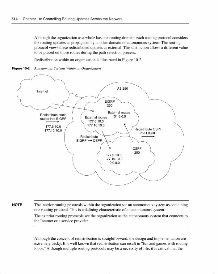
514 Chapter 10: Controlling Routing Updates Across the Network
Although the organization as a whole has one routing domain, each routing protocol considers the routing updates as propagated by another domain or autonomous system. The routing protocol views these redistributed updates as external. This distinction allows a different value to be placed on those routes during the path selection process.
Redistribution within an organization is illustrated in Figure 10-2.
Figure 10-2 Autonomous Systems Within an Organization
NOTE The interior routing protocols within the organization see an autonomous system as containing one routing protocol. This is a defining characteristic of an autonomous system.
The exterior routing protocols see the organization as the autonomous system that connects to the Internet or a service provider.
Although the concept of redistribution is straightforward, the design and implementation are extremely tricky. It is well known that redistribution can result in “fun and games with routing loops.” Although multiple routing protocols may be a necessity of life, it is critical that the
Internet
Redistribute staticroutes into EIGRP
177.6.10.0177.10.10.0
177.6.10.0177.10.10.0
10.0.0.0
RedistributeEIGRP OSPF
External routes177.6.10.0
177.10.10.0
AS 250
EIGRP250
OSPF250
External routes131.6.0.0
Redistribute OSPFinto EIGRP
chpt_01.book Page 514 Thursday, December 21, 2000 6:22 PM
Redistribution Between Routing Protocols 515
implementation and maintenance be managed with a full, documented understanding of both the network and the traffic flows.
To manage the complexity of these networks and to reduce the possibility of routing loops, some level of restriction in the information sent across the various domains is often necessary.
Controlling Routing UpdatesVarious methods enable you to control the routing information sent between routers. These methods include the following:
• Passive interfaces—An interface that does not participate in the routing process. In RIP and IGRP, the process listens but will not send updates. In OSPF and EIGRP, the process neither listens nor sends updates because no neighbor relationship can form.
The interfaces that participate in the interior routing process are controlled by the interface configuration. During configuration, the routing process is instructed via the network command on which interfaces to use. Because most protocols express the networks at the major boundary, interfaces that have no reason to send this protocol’s updates propagate the data across the network. This is not only a waste of bandwidth, but in many cases, it can lead to confusion.
• Default routes—A route used if there is no entry in the routing table for the destination network. If the lookup finds no entry for the desired network and no default network is configured, the packet is dropped.
If the routing process is denied the right to send updates, the downstream routers will have a limited understanding of the network. To resolve this, use default routes. Default routes reduce overhead, add simplicity, and can remove loops.
• Static routes—A route that is manually configured. It takes precedence over routes learned via a routing process because it has lower administrative distance.
If no routing process is configured, static routes may be configured to populate the routing table. This is not practical in a large network because the table cannot learn of changes in the network topology dynamically. In small environments or for stub networks, however, this is an excellent solution.
• The null interface—An imaginary interface that is defined as the next logical hop in a static route. All traffic destined for the remote network is carefully routed into a black hole.
This can be used in a similar way to the passive interface, but it allows for greater granularity in the denied routes.
chpt_01.book Page 515 Thursday, December 21, 2000 6:22 PM
516 Chapter 10: Controlling Routing Updates Across the Network
It is also used to feed routes into another routing protocol. Its allows another mask to be set and is therefore useful when redistribution occurs between a routing protocol that uses VLSM and one that does not. In this way, it aggregates routes as shown in the previous chapter.
• Distribution lists—Access lists applied to the routing process, determining which networks will be accepted into the routing table or sent in updates.
When communicating to another routing process, it is important to control the information sent into the other process. This control is for security, overhead, and management reasons. Access lists afford the greatest control for determining the traffic flow in the network.
• Route maps: Complex access lists permitting conditional programming. If a packet or route matches the criteria defined in a match statement, then changes defined in the set command are performed on the packet or route in question.
NOTE Each of these methods of controlling routing updates is considered in detail later in the chapter.
Figure 10-3 shows the use of the options for controlling routing updates in a large and complex network.
In Figure 10-3, Ethernet 0 has a distribute list that is denying the propagation of the network 140.100.32.0 out of E3, which is the network connected to E2. This may be because network 140.100.32.0 has some security reasons for not being seen by the networks connected to Router B. This network could be a test or an R&D project for the department connecting to Router B, and connectivity would confuse the situation.
S0 and S1 have static routes configured. In the case of S0, this is the connection into the Internet, and the static routes are configured by the ISP. This allows them to connect to the ISP without having to receive dynamic routing updates from the ISP. The routing tables from the ISP containing the Internet routing tables could be huge.
The organization has a default route set so that anyone wanting to flee the organization’s network can send to the default route, thus keeping the routing tables small and the update traffic to a minimum.
On S1, the router’s interface is configured with static routes so that the router at the other end does not need to run a routing protocol. The router at the other end has a default route configured, and the suggestion is that this is a stub network. This ensures that Router C has a simple configuration with few demands on the router.
chpt_01.book Page 516 Thursday, December 21, 2000 6:22 PM
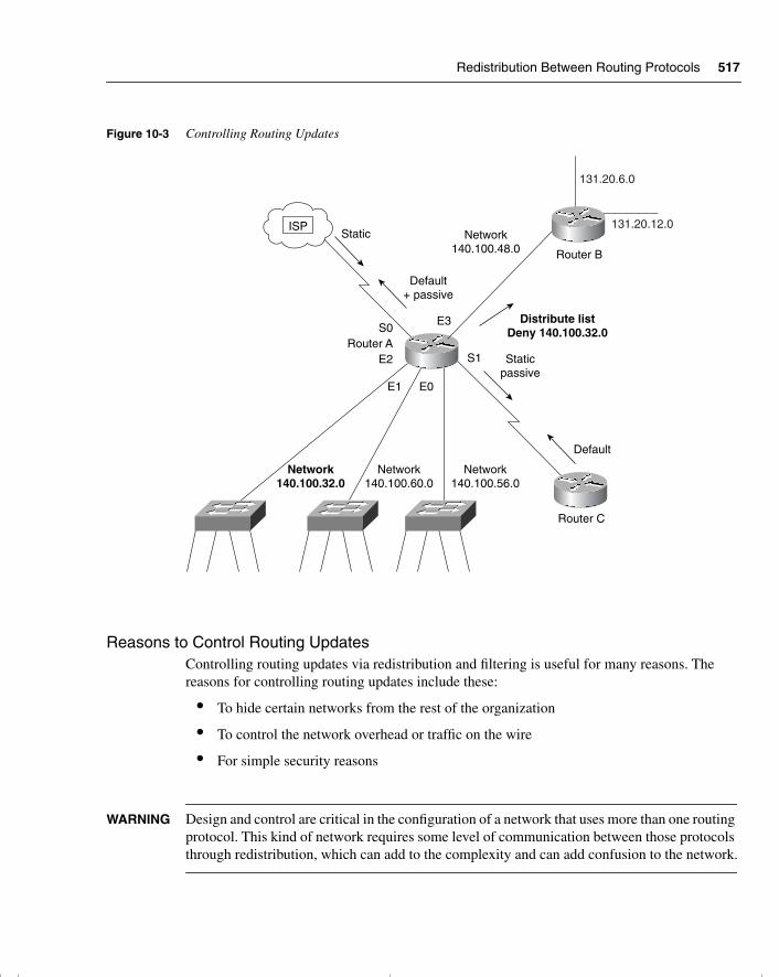
Redistribution Between Routing Protocols 517
Figure 10-3 Controlling Routing Updates
Reasons to Control Routing UpdatesControlling routing updates via redistribution and filtering is useful for many reasons. The reasons for controlling routing updates include these:
• To hide certain networks from the rest of the organization
• To control the network overhead or traffic on the wire
• For simple security reasons
WARNING Design and control are critical in the configuration of a network that uses more than one routing protocol. This kind of network requires some level of communication between those protocols through redistribution, which can add to the complexity and can add confusion to the network.
ISPStatic
Default+ passive
Staticpassive
Default
Router A
Router C
S0
E2
E1
E3
E0
S1
Network140.100.32.0
Network140.100.60.0
Network140.100.56.0
Network140.100.48.0
Distribute listDeny 140.100.32.0
Router B
131.20.6.0
131.20.12.0
chpt_01.book Page 517 Thursday, December 21, 2000 6:22 PM
518 Chapter 10: Controlling Routing Updates Across the Network
The Main Features of RedistributionRedistribution is used when a router is receiving information about remote networks from various sources. Although all the networks are entered into the routing table and routing decisions will be made on all the networks present in the table, a routing protocol propagates only those networks that it learned through its own process. When there is no sharing of network information between the routing processes, this is referred to as ships in the night, or SIN, routing. Redistribution can occur only between processes routing the same Layer 3 protocol. So, for example OSPF, RIP, IGRP, and EIGRP can redistribute routing updates between them because they all support the same TCP/IP stack and share the same routing table. How one redistributes between the routing protocols differs between protocols. However, there can be no network redistribution between AppleTalk and IPX.
Default Redistribution Between Routing ProtocolsEIGRP is a routing protocol that carries updates for multiple protocols. The key to how this works is the separate routing tables held for each protocol, using the routing protocol as the mechanism for the forwarding of updates and path selection. EIGRP supports AppleTalk’s RTMP, IPX’s RIP and NLSP, as well as IP. Automatic redistribution is performed between RTMP and EIGRP, and IPX RIP and EIGRP. EIGRP must be manually redistributed into NLSP. There is also automatic redistribution between IGRP and EIGRP as long as they are members of the same autonomous system.
In Figure 10-4, the routing table for Router B has entries from RIP and OSPF. There are no entries for EIGRP because this is a single network directly connected to the router. You can see that the RIP updates sent out the interfaces do not include networks from OSPF. There are no entries for EIGRP.
Some routing protocols automatically exchange networks, although others require some level of configuration. Table 10-2 shows the subtleties of automatic redistribution.
chpt_01.book Page 518 Thursday, December 21, 2000 6:22 PM
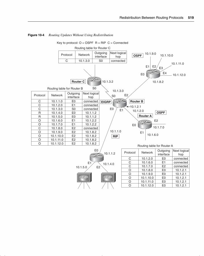
Redistribution Between Routing Protocols 519
Figure 10-4 Routing Updates Without Using Redistribution
Protocol
CCCOOOOO
Network
10.1.2.010.1.6.010.1.7.010.1.8.010.1.9.0
10.1.10.010.1.11.010.1.12.0
Routing table for Router A
Outgoinginterface
Next logicalhop
E0E1E2E0E0E0E0E0
connectedconnectedconnected10.1.2.110.1.2.110.1.2.110.1.2.110.1.2.1
Routing table for Router C
Protocol
C
Network
10.1.3.0
Outgoinginterface
Next logicalhop
S0 connected
Protocol
CCCRROOCOOOO
Network
10.1.1.010.1.2.010.1.3.010.1.4.010.1.5.010.1.6.010.1.7.010.1.8.010.1.9.0
10.1.10.010.1.11.010.1.12.0
Routing table for Router B
Outgoinginterface
Next logicalhop
E0E1S0E0E0E1E1E2E2E2E2E2
connectedconnectedconnected10.1.1.210.1.1.210.1.2.210.1.2.2
connected10.1.8.210.1.8.210.1.8.210.1.8.2
Key to protocol: O = OSPF R = RIP C = Connected
Router C
Router B
S0
S0
E0
E0
E0
10.1.3.2
10.1.3.0
E1
E1
E1
E2
E2 E3
E4
E2
10.1.1.0
E0
E1E2
10.1.1.2
10.1.4.010.1.5.0
Router AOSPF
10.1.7.0
10.1.2.1
10.1.9.010.1.10.0
10.1.11.0
10.1.12.0
10.1.8.2
10.1.2.0
10.1.6.0
OSPF
EIGRP
RIP
chpt_01.book Page 519 Thursday, December 21, 2000 6:22 PM
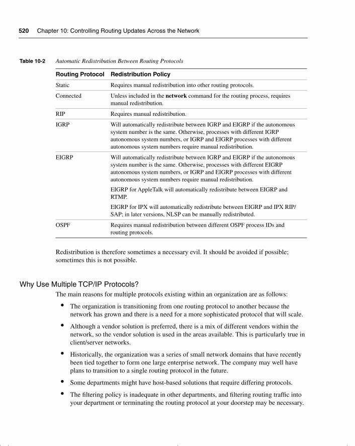
520 Chapter 10: Controlling Routing Updates Across the Network
Redistribution is therefore sometimes a necessary evil. It should be avoided if possible; sometimes this is not possible.
Why Use Multiple TCP/IP Protocols?The main reasons for multiple protocols existing within an organization are as follows:
• The organization is transitioning from one routing protocol to another because the network has grown and there is a need for a more sophisticated protocol that will scale.
• Although a vendor solution is preferred, there is a mix of different vendors within the network, so the vendor solution is used in the areas available. This is particularly true in client/server networks.
• Historically, the organization was a series of small network domains that have recently been tied together to form one large enterprise network. The company may well have plans to transition to a single routing protocol in the future.
• Some departments might have host-based solutions that require differing protocols.
• The filtering policy is inadequate in other departments, and filtering routing traffic into your department or terminating the routing protocol at your doorstep may be necessary.
Table 10-2 Automatic Redistribution Between Routing Protocols
Routing Protocol Redistribution Policy
Static Requires manual redistribution into other routing protocols.
Connected Unless included in the network command for the routing process, requires manual redistribution.
RIP Requires manual redistribution.
IGRP Will automatically redistribute between IGRP and EIGRP if the autonomous system number is the same. Otherwise, processes with different IGRP autonomous system numbers, or IGRP and EIGRP processes with different autonomous system numbers require manual redistribution.
EIGRP Will automatically redistribute between IGRP and EIGRP if the autonomous system number is the same. Otherwise, processes with different EIGRP autonomous system numbers, or IGRP and EIGRP processes with different autonomous system numbers require manual redistribution.
EIGRP for AppleTalk will automatically redistribute between EIGRP and RTMP.
EIGRP for IPX will automatically redistribute between EIGRP and IPX RIP/SAP; in later versions, NLSP can be manually redistributed.
OSPF Requires manual redistribution between different OSPF process IDs and routing protocols.
chpt_01.book Page 520 Thursday, December 21, 2000 6:22 PM
Redistribution Between Routing Protocols 521
• Often after a merger or a takeover, when several companies become one, it takes planning, strategy, and careful analysis to determine the best overall design for the network.
• Politically, there are ideological differences among the different network administrators, which until now have not been resolved.
• In a very large environment, the various domains may have different requirements, making a single solution inefficient. A clear example is in the case of a large multinational corporation, where EIGRP is the protocol used at the access and distribution layer, but BGP is the protocol connecting the core.
If there are so many reasons why a network may have multiple routing processes for one Layer 3 protocol, why is it advisable to use one routing protocol, if possible?
The Reason for Using One Routing ProtocolThe reason is simple for configuring one routing protocol:
The added complexity of having multiple routing processes can cause many problems within the network. These are typically very difficult to troubleshoot because the symptom often appears some distance from the configuration error.
Problems of Configuring Multiple Routing ProtocolsThe problems experienced as a result of multiple routing processes and their redistribution include the following:
• The wrong or a less efficient routing decision being made because of the difference in routing metrics. The choice of the less efficient route is referred to as choosing the suboptimal path.
• A routing loop occurring, in which the data traffic is sent in a circle without ever arriving at the destination. This is normally due to routing feedback, where routers send routing information received from one autonomous system back into that same autonomous system.
• The convergence time of the network increasing because of the different technologies involved. If the routing protocols converge at different rates, this may also cause problems. In some cases, this may result in timeouts and the temporary loss of networks.
Dealing with each of these problems in turn, the selection of the suboptimal path may occur because of the method used to make a routing decision.
chpt_01.book Page 521 Thursday, December 21, 2000 6:22 PM
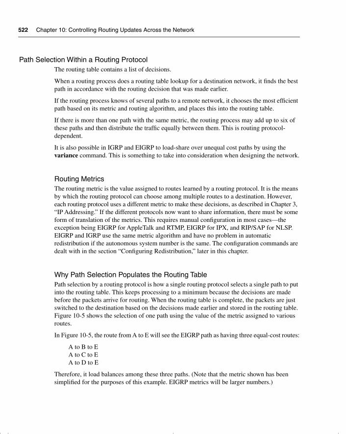
522 Chapter 10: Controlling Routing Updates Across the Network
Path Selection Within a Routing ProtocolThe routing table contains a list of decisions.
When a routing process does a routing table lookup for a destination network, it finds the best path in accordance with the routing decision that was made earlier.
If the routing process knows of several paths to a remote network, it chooses the most efficient path based on its metric and routing algorithm, and places this into the routing table.
If there is more than one path with the same metric, the routing process may add up to six of these paths and then distribute the traffic equally between them. This is routing protocol-dependent.
It is also possible in IGRP and EIGRP to load-share over unequal cost paths by using the variance command. This is something to take into consideration when designing the network.
Routing MetricsThe routing metric is the value assigned to routes learned by a routing protocol. It is the means by which the routing protocol can choose among multiple routes to a destination. However, each routing protocol uses a different metric to make these decisions, as described in Chapter 3, “IP Addressing.” If the different protocols now want to share information, there must be some form of translation of the metrics. This requires manual configuration in most cases—the exception being EIGRP for AppleTalk and RTMP, EIGRP for IPX, and RIP/SAP for NLSP. EIGRP and IGRP use the same metric algorithm and have no problem in automatic redistribution if the autonomous system number is the same. The configuration commands are dealt with in the section “Configuring Redistribution,” later in this chapter.
Why Path Selection Populates the Routing TablePath selection by a routing protocol is how a single routing protocol selects a single path to put into the routing table. This keeps processing to a minimum because the decisions are made before the packets arrive for routing. When the routing table is complete, the packets are just switched to the destination based on the decisions made earlier and stored in the routing table. Figure 10-5 shows the selection of one path using the value of the metric assigned to various routes.
In Figure 10-5, the route from A to E will see the EIGRP path as having three equal-cost routes:
A to B to EA to C to EA to D to E
Therefore, it load balances among these three paths. (Note that the metric shown has been simplified for the purposes of this example. EIGRP metrics will be larger numbers.)
chpt_01.book Page 522 Thursday, December 21, 2000 6:22 PM
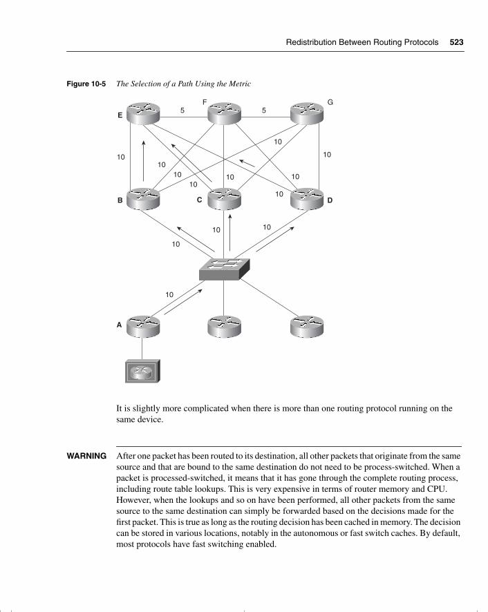
Redistribution Between Routing Protocols 523
Figure 10-5 The Selection of a Path Using the Metric
It is slightly more complicated when there is more than one routing protocol running on the same device.
WARNING After one packet has been routed to its destination, all other packets that originate from the same source and that are bound to the same destination do not need to be process-switched. When a packet is processed-switched, it means that it has gone through the complete routing process, including route table lookups. This is very expensive in terms of router memory and CPU. However, when the lookups and so on have been performed, all other packets from the same source to the same destination can simply be forwarded based on the decisions made for the first packet. This is true as long as the routing decision has been cached in memory. The decision can be stored in various locations, notably in the autonomous or fast switch caches. By default, most protocols have fast switching enabled.
5 5E
B C
A
1010
1010
10
10
10
10
10
10
10
10
10
D
F G
chpt_01.book Page 523 Thursday, December 21, 2000 6:22 PM
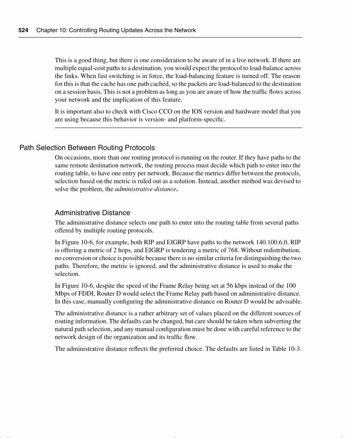
524 Chapter 10: Controlling Routing Updates Across the Network
This is a good thing, but there is one consideration to be aware of in a live network. If there are multiple equal-cost paths to a destination, you would expect the protocol to load-balance across the links. When fast switching is in force, the load-balancing feature is turned off. The reason for this is that the cache has one path cached, so the packets are load-balanced to the destination on a session basis. This is not a problem as long as you are aware of how the traffic flows across your network and the implication of this feature.
It is important also to check with Cisco CCO on the IOS version and hardware model that you are using because this behavior is version- and platform-specific.
Path Selection Between Routing ProtocolsOn occasions, more than one routing protocol is running on the router. If they have paths to the same remote destination network, the routing process must decide which path to enter into the routing table, to have one entry per network. Because the metrics differ between the protocols, selection based on the metric is ruled out as a solution. Instead, another method was devised to solve the problem, the administrative distance.
Administrative DistanceThe administrative distance selects one path to enter into the routing table from several paths offered by multiple routing protocols.
In Figure 10-6, for example, both RIP and EIGRP have paths to the network 140.100.6.0. RIP is offering a metric of 2 hops, and EIGRP is tendering a metric of 768. Without redistribution, no conversion or choice is possible because there is no similar criteria for distinguishing the two paths. Therefore, the metric is ignored, and the administrative distance is used to make the selection.
In Figure 10-6, despite the speed of the Frame Relay being set at 56 kbps instead of the 100 Mbps of FDDI, Router D would select the Frame Relay path based on administrative distance. In this case, manually configuring the administrative distance on Router D would be advisable.
The administrative distance is a rather arbitrary set of values placed on the different sources of routing information. The defaults can be changed, but care should be taken when subverting the natural path selection, and any manual configuration must be done with careful reference to the network design of the organization and its traffic flow.
The administrative distance reflects the preferred choice. The defaults are listed in Table 10-3.
chpt_01.book Page 524 Thursday, December 21, 2000 6:22 PM
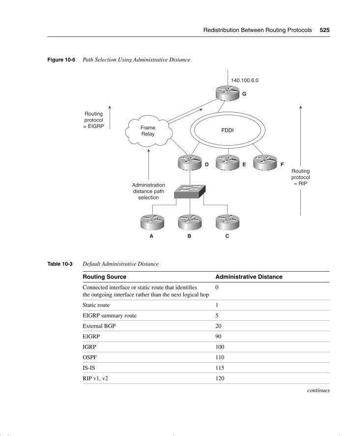
Redistribution Between Routing Protocols 525
Figure 10-6 Path Selection Using Administrative Distance
Table 10-3 Default Administrative Distance
Routing Source Administrative Distance
Connected interface or static route that identifies the outgoing interface rather than the next logical hop
0
Static route 1
EIGRP summary route 5
External BGP 20
EIGRP 90
IGRP 100
OSPF 110
IS-IS 115
RIP v1, v2 120
continues
D E
G
F
A B C
FDDIFrameRelay
Administrationdistance path
selection
140.100.6.0
Routingprotocol= EIGRP
Routingprotocol= RIP
chpt_01.book Page 525 Thursday, December 21, 2000 6:22 PM
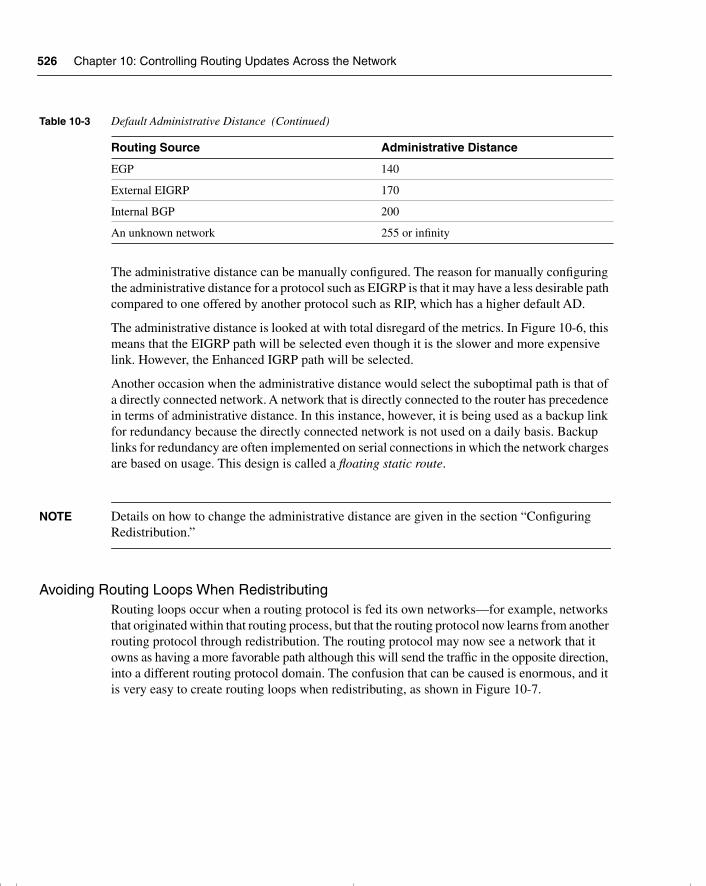
526 Chapter 10: Controlling Routing Updates Across the Network
The administrative distance can be manually configured. The reason for manually configuring the administrative distance for a protocol such as EIGRP is that it may have a less desirable path compared to one offered by another protocol such as RIP, which has a higher default AD.
The administrative distance is looked at with total disregard of the metrics. In Figure 10-6, this means that the EIGRP path will be selected even though it is the slower and more expensive link. However, the Enhanced IGRP path will be selected.
Another occasion when the administrative distance would select the suboptimal path is that of a directly connected network. A network that is directly connected to the router has precedence in terms of administrative distance. In this instance, however, it is being used as a backup link for redundancy because the directly connected network is not used on a daily basis. Backup links for redundancy are often implemented on serial connections in which the network charges are based on usage. This design is called a floating static route.
NOTE Details on how to change the administrative distance are given in the section “Configuring Redistribution.”
Avoiding Routing Loops When Redistributing Routing loops occur when a routing protocol is fed its own networks—for example, networks that originated within that routing process, but that the routing protocol now learns from another routing protocol through redistribution. The routing protocol may now see a network that it owns as having a more favorable path although this will send the traffic in the opposite direction, into a different routing protocol domain. The confusion that can be caused is enormous, and it is very easy to create routing loops when redistributing, as shown in Figure 10-7.
EGP 140
External EIGRP 170
Internal BGP 200
An unknown network 255 or infinity
Table 10-3 Default Administrative Distance (Continued)
Routing Source Administrative Distance
chpt_01.book Page 526 Thursday, December 21, 2000 6:22 PM
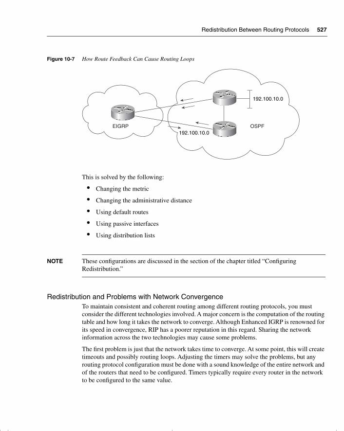
Redistribution Between Routing Protocols 527
Figure 10-7 How Route Feedback Can Cause Routing Loops
This is solved by the following:
• Changing the metric
• Changing the administrative distance
• Using default routes
• Using passive interfaces
• Using distribution lists
NOTE These configurations are discussed in the section of the chapter titled “Configuring Redistribution.”
Redistribution and Problems with Network ConvergenceTo maintain consistent and coherent routing among different routing protocols, you must consider the different technologies involved. A major concern is the computation of the routing table and how long it takes the network to converge. Although Enhanced IGRP is renowned for its speed in convergence, RIP has a poorer reputation in this regard. Sharing the network information across the two technologies may cause some problems.
The first problem is just that the network takes time to converge. At some point, this will create timeouts and possibly routing loops. Adjusting the timers may solve the problems, but any routing protocol configuration must be done with a sound knowledge of the entire network and of the routers that need to be configured. Timers typically require every router in the network to be configured to the same value.
EIGRP OSPF
192.100.10.0
192.100.10.0
chpt_01.book Page 527 Thursday, December 21, 2000 6:22 PM
528 Chapter 10: Controlling Routing Updates Across the Network
Guidelines in Network Design to Avoid Routing Loops The principles are summarized as follows:
• Have a sound knowledge and clear documentation of the following:
— The network topology (physical and logical)
— The routing protocol domains
— The traffic flow
• Do not overlap routing protocols. It is much easier if the different protocols can be clearly delineated into separate domains, with routers acting in a similar function to Area Border Routers in OSPF. This is often referred to as the core and edge protocols.
— Identify the boundary routers on which redistribution is to be configured.
— Determine which protocol is the core and which protocol is the edge protocol.
— Determine the direction of redistribution, into which routing protocol are the routers to be distributed.
• If distribution is needed, ensure that it is a one-way distribution, to avoid networks being fed back into the originating domain. Use default routes to facilitate the use of one-way distribution, if necessary.
• If two-way distribution cannot be avoided, the mechanisms described in this section, such as the following, can help you avoid problems:
— Manually configuring the metric
— Manually configuring the administrative distance
— Using distribution access lists
The concepts of redistribution are detailed in the following examples with configuration scripts. This will reinforce the concepts and understanding of the technology.
Configuring RedistributionRedistribution configuration is very specific to the routing protocol itself. Before any implementation is contemplated, reference should be made to the configuration guides from Cisco.
Generic Steps Required for Redistribution All protocols require the following steps for redistribution:
• Configure redistribution.
chpt_01.book Page 528 Thursday, December 21, 2000 6:22 PM
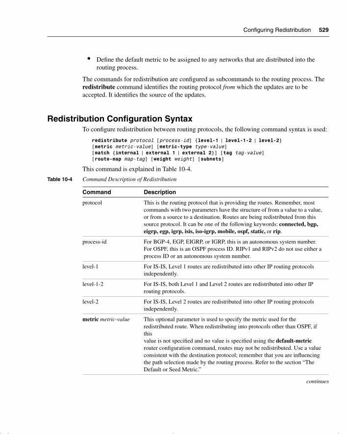
Configuring Redistribution 529
• Define the default metric to be assigned to any networks that are distributed into the routing process.
The commands for redistribution are configured as subcommands to the routing process. The redistribute command identifies the routing protocol from which the updates are to be accepted. It identifies the source of the updates.
Redistribution Configuration SyntaxTo configure redistribution between routing protocols, the following command syntax is used:
redistribute protocol [process-id] {level-1 | level-1-2 | level-2}[metric metric-value] [metric-type type-value] [match {internal | external 1 | external 2}] [tag tag-value][route-map map-tag] [weight weight] [subnets]
This command is explained in Table 10-4.
Table 10-4 Command Description of Redistribution
Command Description
protocol This is the routing protocol that is providing the routes. Remember, most commands with two parameters have the structure of from a value to a value, or from a source to a destination. Routes are being redistributed from this source protocol. It can be one of the following keywords: connected, bgp, eigrp, egp, igrp, isis, iso-igrp, mobile, ospf, static, or rip.
process-id For BGP-4, EGP, EIGRP, or IGRP, this is an autonomous system number. For OSPF, this is an OSPF process ID. RIPv1 and RIPv2 do not use either a process ID or an autonomous system number.
level-1 For IS-IS, Level 1 routes are redistributed into other IP routing protocols independently.
level-1-2 For IS-IS, both Level 1 and Level 2 routes are redistributed into other IP routing protocols.
level-2 For IS-IS, Level 2 routes are redistributed into other IP routing protocols independently.
metric metric-value This optional parameter is used to specify the metric used for the redistributed route. When redistributing into protocols other than OSPF, if this value is not specified and no value is specified using the default-metric router configuration command, routes may not be redistributed. Use a value consistent with the destination protocol; remember that you are influencing the path selection made by the routing process. Refer to the section “The Default or Seed Metric.”
continues
chpt_01.book Page 529 Thursday, December 21, 2000 6:22 PM
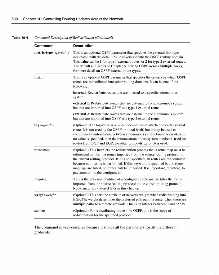
530 Chapter 10: Controlling Routing Updates Across the Network
The command is very complex because it shows all the parameters for all the different protocols.
metric-type type-value This is an optional OSPF parameter that specifies the external link type associated with the default route advertised into the OSPF routing domain. This value can be 1 for type 1 external routes, or 2 for type 2 external routes. The default is 2. Refer to Chapter 6, “Using OSPF Across Multiple Areas,” for more detail on OSPF external route types.
match This is an optional OSPF parameter that specifies the criteria by which OSPF routes are redistributed into other routing domains. It can be one of the following:
internal: Redistribute routes that are internal to a specific autonomous system.
external 1: Redistribute routes that are external to the autonomous system but that are imported into OSPF as a type 1 external route.
external 2: Redistribute routes that are external to the autonomous system but that are imported into OSPF as a type 2 external route.
tag tag-value (Optional) The tag-value is a 32-bit decimal value attached to each external route. It is not used by the OSPF protocol itself, but it may be used to communicate information between autonomous system boundary routers. If no value is specified, then the remote autonomous system number is used for routes from BGP and EGP; for other protocols, zero (0) is used.
route-map (Optional) This instructs the redistribution process that a route map must be referenced to filter the routes imported from the source routing protocol to the current routing protocol. If it is not specified, all routes are redistributed because no filtering is performed. If this keyword is specified but no route map tags are listed, no routes will be imported. It is important, therefore, to pay attention to the configuration.
map-tag This is the optional identifier of a configured route map to filter the routes imported from the source routing protocol to the current routing protocol. Route maps are covered later in this chapter.
weight weight (Optional) This sets the attribute of network weight when redistributing into BGP. The weight determines the preferred path out of a router when there are multiple paths to a remote network. This is an integer between 0 and 65535.
subnets (Optional) For redistributing routes into OSPF, this is the scope of redistribution for the specified protocol.
Table 10-4 Command Description of Redistribution (Continued)
Command Description
chpt_01.book Page 530 Thursday, December 21, 2000 6:22 PM
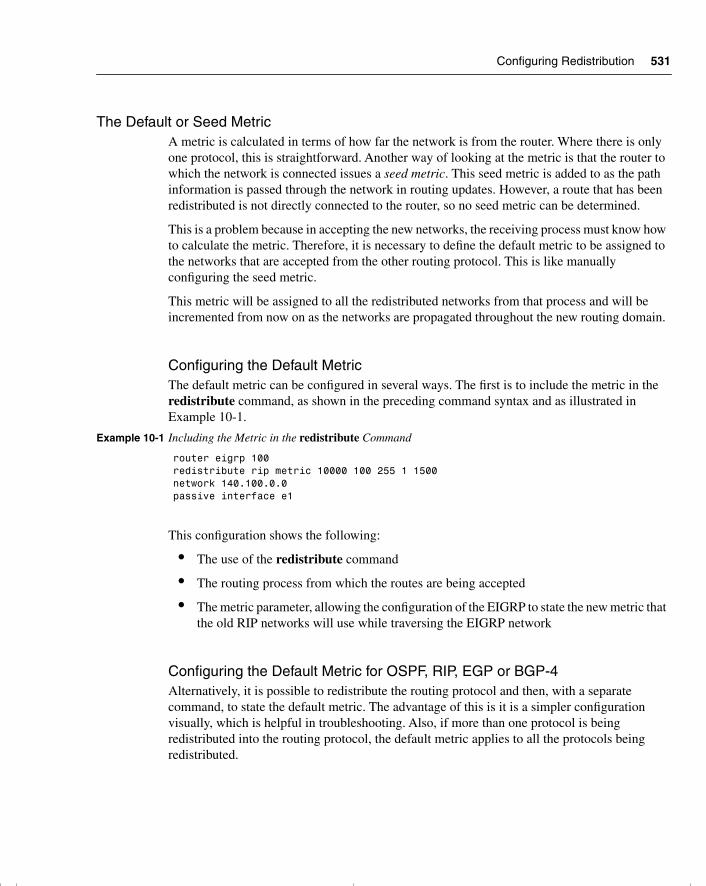
Configuring Redistribution 531
The Default or Seed MetricA metric is calculated in terms of how far the network is from the router. Where there is only one protocol, this is straightforward. Another way of looking at the metric is that the router to which the network is connected issues a seed metric. This seed metric is added to as the path information is passed through the network in routing updates. However, a route that has been redistributed is not directly connected to the router, so no seed metric can be determined.
This is a problem because in accepting the new networks, the receiving process must know how to calculate the metric. Therefore, it is necessary to define the default metric to be assigned to the networks that are accepted from the other routing protocol. This is like manually configuring the seed metric.
This metric will be assigned to all the redistributed networks from that process and will be incremented from now on as the networks are propagated throughout the new routing domain.
Configuring the Default MetricThe default metric can be configured in several ways. The first is to include the metric in the redistribute command, as shown in the preceding command syntax and as illustrated in Example 10-1.
This configuration shows the following:
• The use of the redistribute command
• The routing process from which the routes are being accepted
• The metric parameter, allowing the configuration of the EIGRP to state the new metric that the old RIP networks will use while traversing the EIGRP network
Configuring the Default Metric for OSPF, RIP, EGP or BGP-4 Alternatively, it is possible to redistribute the routing protocol and then, with a separate command, to state the default metric. The advantage of this is it is a simpler configuration visually, which is helpful in troubleshooting. Also, if more than one protocol is being redistributed into the routing protocol, the default metric applies to all the protocols being redistributed.
Example 10-1 Including the Metric in the redistribute Command
router eigrp 100redistribute rip metric 10000 100 255 1 1500network 140.100.0.0passive interface e1
chpt_01.book Page 531 Thursday, December 21, 2000 6:22 PM
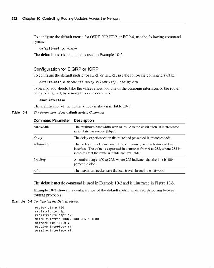
532 Chapter 10: Controlling Routing Updates Across the Network
To configure the default metric for OSPF, RIP, EGP, or BGP-4, use the following command syntax:
default-metric number
The default-metric command is used in Example 10-2.
Configuration for EIGRP or IGRPTo configure the default metric for IGRP or EIGRP, use the following command syntax:
default-metric bandwidth delay reliability loading mtu
Typically, you should take the values shown on one of the outgoing interfaces of the router being configured, by issuing this exec command:
show interface
The significance of the metric values is shown in Table 10-5.
The default metric command is used in Example 10-2 and is illustrated in Figure 10-8.
Example 10-2 shows the configuration of the default metric when redistributing between routing protocols.
Table 10-5 The Parameters of the default metric Command
Command Parameter Description
bandwidth The minimum bandwidth seen on route to the destination. It is presented in kilobits/per second (kbps).
delay The delay experienced on the route and presented in microseconds.
reliability The probability of a successful transmission given the history of this interface. The value is expressed in a number from 0 to 255, where 255 is indicates that the route is stable and available.
loading A number range of 0 to 255, where 255 indicates that the line is 100 percent loaded.
mtu The maximum packet size that can travel through the network.
Example 10-2 Configuring the Default Metric
router eigrp 100redistribute rip redistribute ospf 10default-metric 10000 100 255 1 1500network 140.100.0.0passive interface e1passive interface e2
chpt_01.book Page 532 Thursday, December 21, 2000 6:22 PM
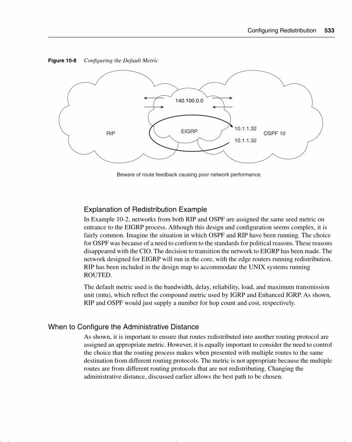
Configuring Redistribution 533
Figure 10-8 Configuring the Default Metric
Explanation of Redistribution ExampleIn Example 10-2, networks from both RIP and OSPF are assigned the same seed metric on entrance to the EIGRP process. Although this design and configuration seems complex, it is fairly common. Imagine the situation in which OSPF and RIP have been running. The choice for OSPF was because of a need to conform to the standards for political reasons. These reasons disappeared with the CIO. The decision to transition the network to EIGRP has been made. The network designed for EIGRP will run in the core, with the edge routers running redistribution. RIP has been included in the design map to accommodate the UNIX systems running ROUTED.
The default metric used is the bandwidth, delay, reliability, load, and maximum transmission unit (mtu), which reflect the compound metric used by IGRP and Enhanced IGRP. As shown, RIP and OSPF would just supply a number for hop count and cost, respectively.
When to Configure the Administrative DistanceAs shown, it is important to ensure that routes redistributed into another routing protocol are assigned an appropriate metric. However, it is equally important to consider the need to control the choice that the routing process makes when presented with multiple routes to the same destination from different routing protocols. The metric is not appropriate because the multiple routes are from different routing protocols that are not redistributing. Changing the administrative distance, discussed earlier allows the best path to be chosen.
OSPF 10RIP
140.100.0.0
EIGRP
Beware of route feedback causing poor network performance.
10.1.1.32
10.1.1.32
chpt_01.book Page 533 Thursday, December 21, 2000 6:22 PM
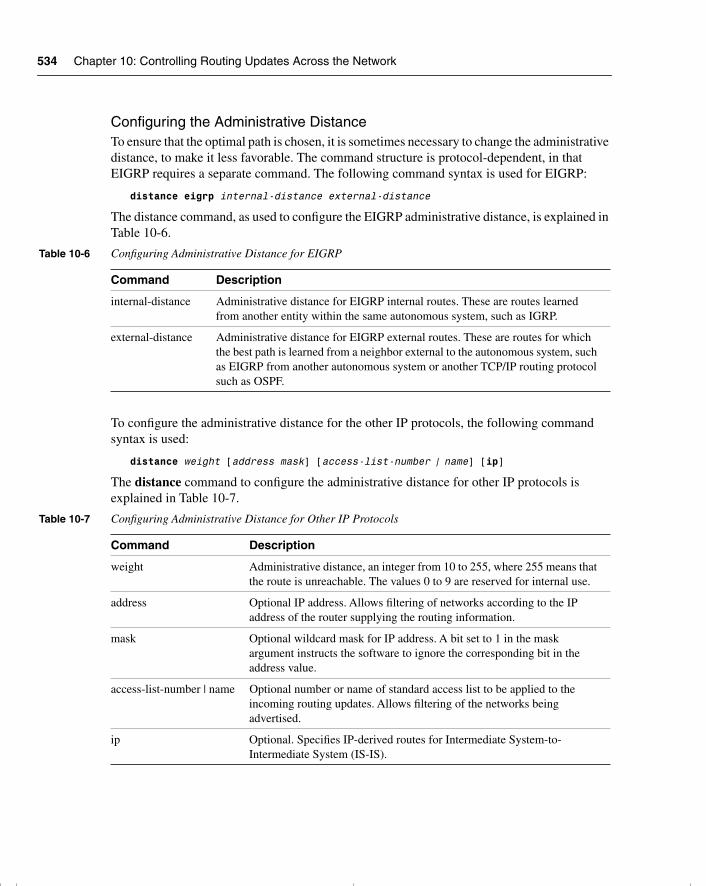
534 Chapter 10: Controlling Routing Updates Across the Network
Configuring the Administrative DistanceTo ensure that the optimal path is chosen, it is sometimes necessary to change the administrative distance, to make it less favorable. The command structure is protocol-dependent, in that EIGRP requires a separate command. The following command syntax is used for EIGRP:
distance eigrp internal-distance external-distance
The distance command, as used to configure the EIGRP administrative distance, is explained in Table 10-6.
To configure the administrative distance for the other IP protocols, the following command syntax is used:
distance weight [address mask] [access-list-number | name] [ip]
The distance command to configure the administrative distance for other IP protocols is explained in Table 10-7.
Table 10-6 Configuring Administrative Distance for EIGRP
Command Description
internal-distance Administrative distance for EIGRP internal routes. These are routes learned from another entity within the same autonomous system, such as IGRP.
external-distance Administrative distance for EIGRP external routes. These are routes for which the best path is learned from a neighbor external to the autonomous system, such as EIGRP from another autonomous system or another TCP/IP routing protocol such as OSPF.
Table 10-7 Configuring Administrative Distance for Other IP Protocols
Command Description
weight Administrative distance, an integer from 10 to 255, where 255 means that the route is unreachable. The values 0 to 9 are reserved for internal use.
address Optional IP address. Allows filtering of networks according to the IP address of the router supplying the routing information.
mask Optional wildcard mask for IP address. A bit set to 1 in the mask argument instructs the software to ignore the corresponding bit in the address value.
access-list-number | name Optional number or name of standard access list to be applied to the incoming routing updates. Allows filtering of the networks being advertised.
ip Optional. Specifies IP-derived routes for Intermediate System-to-Intermediate System (IS-IS).
chpt_01.book Page 534 Thursday, December 21, 2000 6:22 PM
Configuring Redistribution 535
The Passive InterfaceThe passive interface is the interface that listens but does not speak. It is used for routing protocols that send updates through every interface with an address that is included in the network command. If the routing protocol is not running on the next-hop router, it is a waste of time to send updates out of the interface.
The command reduces the spending of limited resources without compromising the integrity of the router. The router processes all routes received on an interface.
The command syntax to configure a passive interface is as follows:
passive-interface type number
where type and number, indicate the interface to be made passive.
Static RoutesAnother method of controlling routes is to manually configure the entries into the routing table. The reasons for doing this include the following:
• This may be done to prevent the need for a routing protocol to run on the network, reducing the network overhead to nil, zero, and zilch. This is used in dialup lines (dial-on-demand routing).
• This also may be done if there are two autonomous systems that do not need to exchange the entire routing table, but simply a few routes.
• The other reason is to change the mask of the network. For example, as seen in BGP-4, you can statically define a supernet and redistribute the static route into the BGP-4 process. This is also done when redistributing from a routing protocol that understands VLSM to one that does not.
The following explains the syntax for configuring the static route:
ip route prefix mask address [distance] [tag tag] [permanent]
This defines the path by stating the next-hop router to which to send the traffic. This configuration can be used only if the network address for the next-hop router is in the routing table. If the static route needs to be advertised to other routers, it should be redistributed.
ip route prefix mask interface [distance] [tag tag] [permanent]
In some versions of the IOS, this route is automatically redistributed because it is viewed as a connected network, as long as the output interface is referred in the static route instead of an IP address.
Table 10-8 explains the options available in the static route command.
chpt_01.book Page 535 Thursday, December 21, 2000 6:22 PM
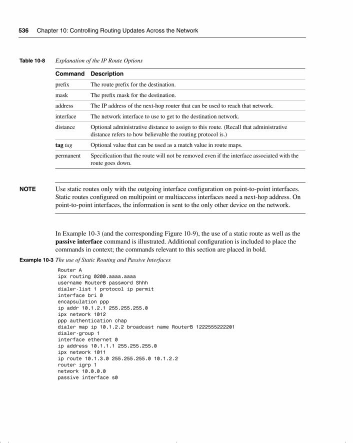
536 Chapter 10: Controlling Routing Updates Across the Network
NOTE Use static routes only with the outgoing interface configuration on point-to-point interfaces. Static routes configured on multipoint or multiaccess interfaces need a next-hop address. On point-to-point interfaces, the information is sent to the only other device on the network.
In Example 10-3 (and the corresponding Figure 10-9), the use of a static route as well as the passive interface command is illustrated. Additional configuration is included to place the commands in context; the commands relevant to this section are placed in bold.
Table 10-8 Explanation of the IP Route Options
Command Description
prefix The route prefix for the destination.
mask The prefix mask for the destination.
address The IP address of the next-hop router that can be used to reach that network.
interface The network interface to use to get to the destination network.
distance Optional administrative distance to assign to this route. (Recall that administrative distance refers to how believable the routing protocol is.)
tag tag Optional value that can be used as a match value in route maps.
permanent Specification that the route will not be removed even if the interface associated with the route goes down.
Example 10-3 The use of Static Routing and Passive Interfaces
Router Aipx routing 0200.aaaa.aaaausername RouterB password Shhhdialer-list 1 protocol ip permitinterface bri 0encapsulation pppip addr 10.1.2.1 255.255.255.0ipx network 1012ppp authentication chapdialer map ip 10.1.2.2 broadcast name RouterB 1222555222201dialer-group 1interface ethernet 0ip address 10.1.1.1 255.255.255.0ipx network 1011ip route 10.1.3.0 255.255.255.0 10.1.2.2 router igrp 1network 10.0.0.0passive interface s0
chpt_01.book Page 536 Thursday, December 21, 2000 6:22 PM
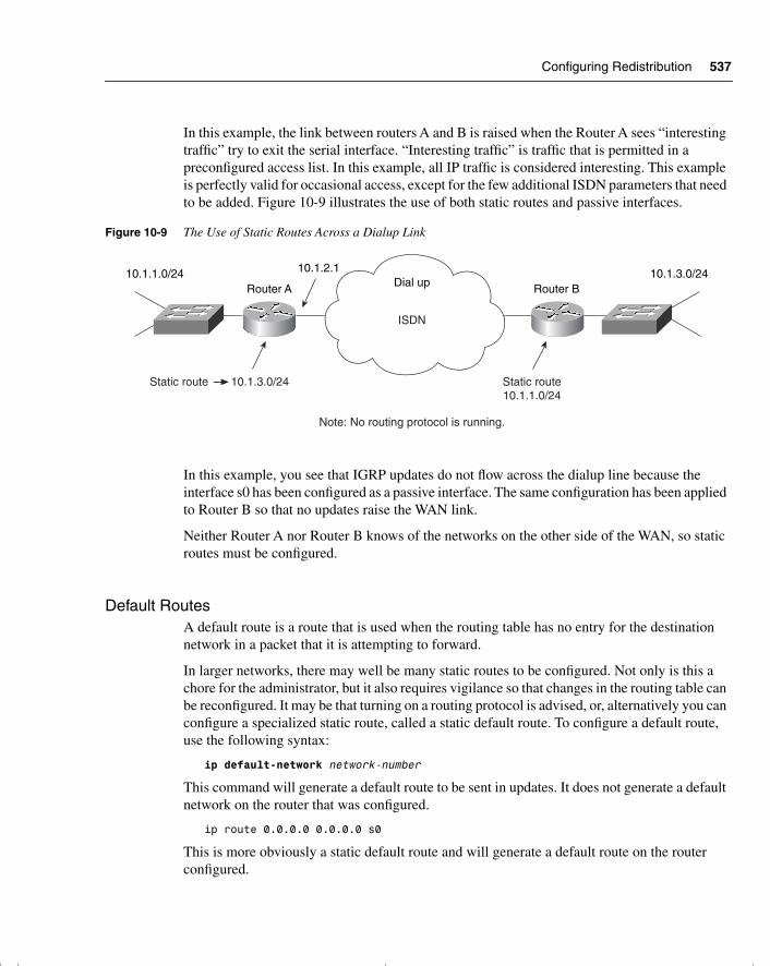
Configuring Redistribution 537
In this example, the link between routers A and B is raised when the Router A sees “interesting traffic” try to exit the serial interface. “Interesting traffic” is traffic that is permitted in a preconfigured access list. In this example, all IP traffic is considered interesting. This example is perfectly valid for occasional access, except for the few additional ISDN parameters that need to be added. Figure 10-9 illustrates the use of both static routes and passive interfaces.
Figure 10-9 The Use of Static Routes Across a Dialup Link
In this example, you see that IGRP updates do not flow across the dialup line because the interface s0 has been configured as a passive interface. The same configuration has been applied to Router B so that no updates raise the WAN link.
Neither Router A nor Router B knows of the networks on the other side of the WAN, so static routes must be configured.
Default RoutesA default route is a route that is used when the routing table has no entry for the destination network in a packet that it is attempting to forward.
In larger networks, there may well be many static routes to be configured. Not only is this a chore for the administrator, but it also requires vigilance so that changes in the routing table can be reconfigured. It may be that turning on a routing protocol is advised, or, alternatively you can configure a specialized static route, called a static default route. To configure a default route, use the following syntax:
ip default-network network-number
This command will generate a default route to be sent in updates. It does not generate a default network on the router that was configured.
ip route 0.0.0.0 0.0.0.0 s0
This is more obviously a static default route and will generate a default route on the router configured.
Dial up
ISDN
Note: No routing protocol is running.
10.1.1.0/24 10.1.3.0/2410.1.2.1
Router A Router B
Static route 10.1.3.0/24 Static route10.1.1.0/24
chpt_01.book Page 537 Thursday, December 21, 2000 6:22 PM
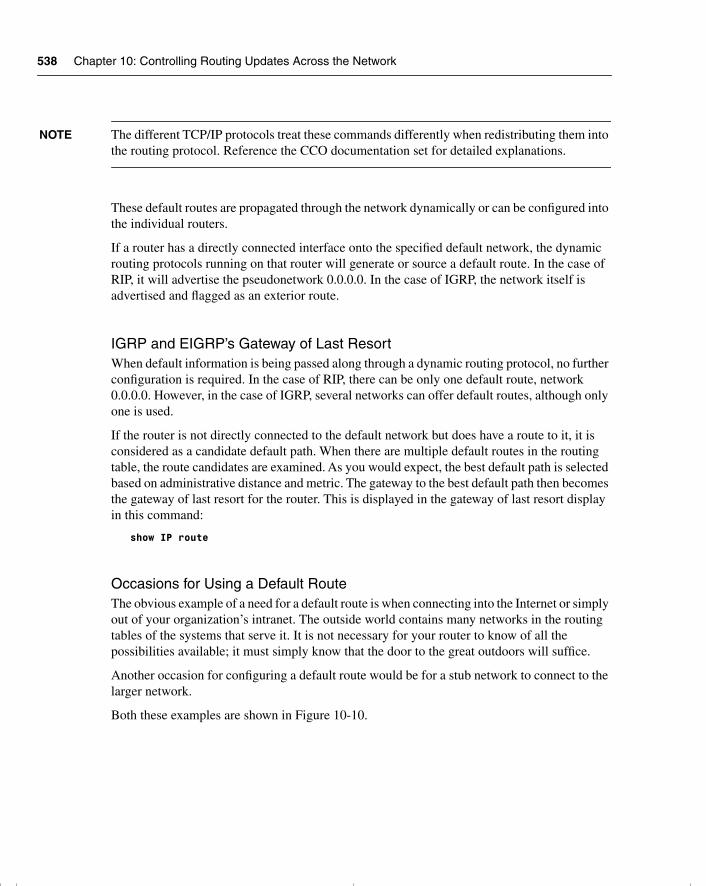
538 Chapter 10: Controlling Routing Updates Across the Network
NOTE The different TCP/IP protocols treat these commands differently when redistributing them into the routing protocol. Reference the CCO documentation set for detailed explanations.
These default routes are propagated through the network dynamically or can be configured into the individual routers.
If a router has a directly connected interface onto the specified default network, the dynamic routing protocols running on that router will generate or source a default route. In the case of RIP, it will advertise the pseudonetwork 0.0.0.0. In the case of IGRP, the network itself is advertised and flagged as an exterior route.
IGRP and EIGRP’s Gateway of Last ResortWhen default information is being passed along through a dynamic routing protocol, no further configuration is required. In the case of RIP, there can be only one default route, network 0.0.0.0. However, in the case of IGRP, several networks can offer default routes, although only one is used.
If the router is not directly connected to the default network but does have a route to it, it is considered as a candidate default path. When there are multiple default routes in the routing table, the route candidates are examined. As you would expect, the best default path is selected based on administrative distance and metric. The gateway to the best default path then becomes the gateway of last resort for the router. This is displayed in the gateway of last resort display in this command:
show IP route
Occasions for Using a Default RouteThe obvious example of a need for a default route is when connecting into the Internet or simply out of your organization’s intranet. The outside world contains many networks in the routing tables of the systems that serve it. It is not necessary for your router to know of all the possibilities available; it must simply know that the door to the great outdoors will suffice.
Another occasion for configuring a default route would be for a stub network to connect to the larger network.
Both these examples are shown in Figure 10-10.
chpt_01.book Page 538 Thursday, December 21, 2000 6:22 PM
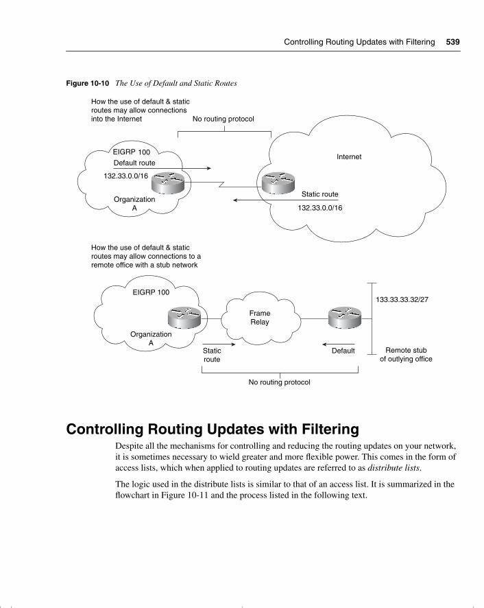
Controlling Routing Updates with Filtering 539
Figure 10-10 The Use of Default and Static Routes
Controlling Routing Updates with FilteringDespite all the mechanisms for controlling and reducing the routing updates on your network, it is sometimes necessary to wield greater and more flexible power. This comes in the form of access lists, which when applied to routing updates are referred to as distribute lists.
The logic used in the distribute lists is similar to that of an access list. It is summarized in the flowchart in Figure 10-11 and the process listed in the following text.
How the use of default & staticroutes may allow connectionsinto the Internet
How the use of default & staticroutes may allow connections to aremote office with a stub network
EIGRP
Default route
132.33.0.0/16
OrganizationA
No routing protocol
Static route
132.33.0.0/16
Internet
FrameRelay
EIGRP 100
OrganizationA
No routing protocol
Staticroute
Default Remote stubof outlying office
133.33.33.32/27
100
chpt_01.book Page 539 Thursday, December 21, 2000 6:22 PM
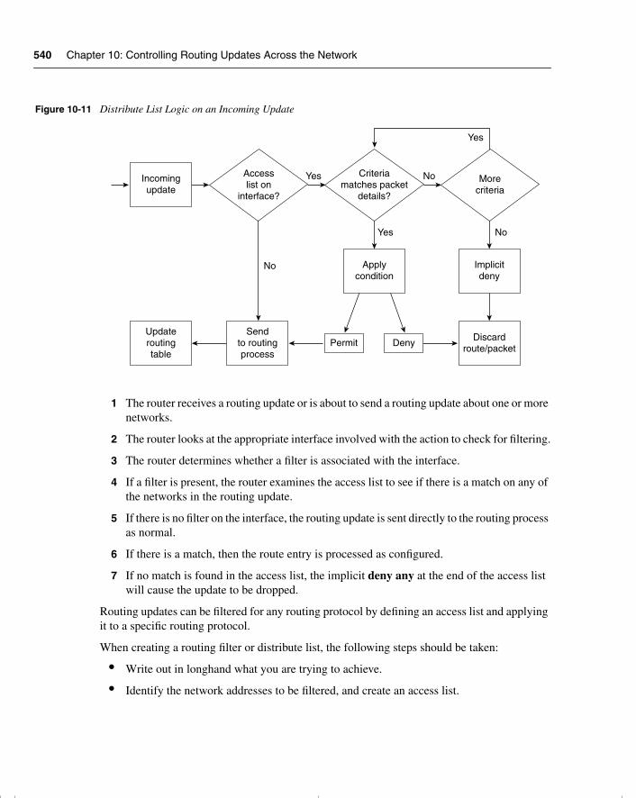
540 Chapter 10: Controlling Routing Updates Across the Network
Figure 10-11 Distribute List Logic on an Incoming Update
1 The router receives a routing update or is about to send a routing update about one or more networks.
2 The router looks at the appropriate interface involved with the action to check for filtering.
3 The router determines whether a filter is associated with the interface.
4 If a filter is present, the router examines the access list to see if there is a match on any of the networks in the routing update.
5 If there is no filter on the interface, the routing update is sent directly to the routing process as normal.
6 If there is a match, then the route entry is processed as configured.
7 If no match is found in the access list, the implicit deny any at the end of the access list will cause the update to be dropped.
Routing updates can be filtered for any routing protocol by defining an access list and applying it to a specific routing protocol.
When creating a routing filter or distribute list, the following steps should be taken:
• Write out in longhand what you are trying to achieve.
• Identify the network addresses to be filtered, and create an access list.
YesIncomingupdate
Updateroutingtable
Permit Deny
Implicitdeny
Discardroute/packet
Sendto routingprocess
Applycondition
Accesslist on
interface?
No
Yes No
No
Criteriamatches packet
details?
Yes
Morecriteria
chpt_01.book Page 540 Thursday, December 21, 2000 6:22 PM
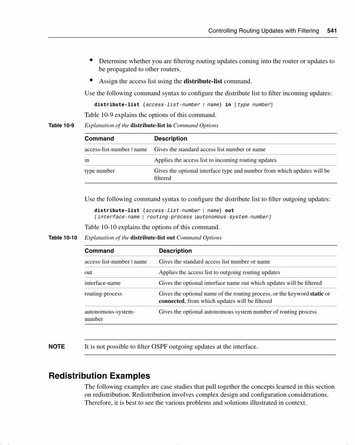
Controlling Routing Updates with Filtering 541
• Determine whether you are filtering routing updates coming into the router or updates to be propagated to other routers.
• Assign the access list using the distribute-list command.
Use the following command syntax to configure the distribute list to filter incoming updates:
distribute-list {access-list-number | name} in [type number]
Table 10-9 explains the options of this command.
Use the following command syntax to configure the distribute list to filter outgoing updates:
distribute-list {access-list-number | name} out [interface-name | routing-process |autonomous-system-number]
Table 10-10 explains the options of this command.
NOTE It is not possible to filter OSPF outgoing updates at the interface.
Redistribution ExamplesThe following examples are case studies that pull together the concepts learned in this section on redistribution. Redistribution involves complex design and configuration considerations. Therefore, it is best to see the various problems and solutions illustrated in context.
Table 10-9 Explanation of the distribute-list in Command Options
Command Description
access-list-number | name Gives the standard access list number or name
in Applies the access list to incoming routing updates
type number Gives the optional interface type and number from which updates will be filtered
Table 10-10 Explanation of the distribute-list out Command Options
Command Description
access-list-number | name Gives the standard access list number or name
out Applies the access list to outgoing routing updates
interface-name Gives the optional interface name out which updates will be filtered
routing-process Gives the optional name of the routing process, or the keyword static or connected, from which updates will be filtered
autonomous-system-number
Gives the optional autonomous system number of routing process
chpt_01.book Page 541 Thursday, December 21, 2000 6:22 PM
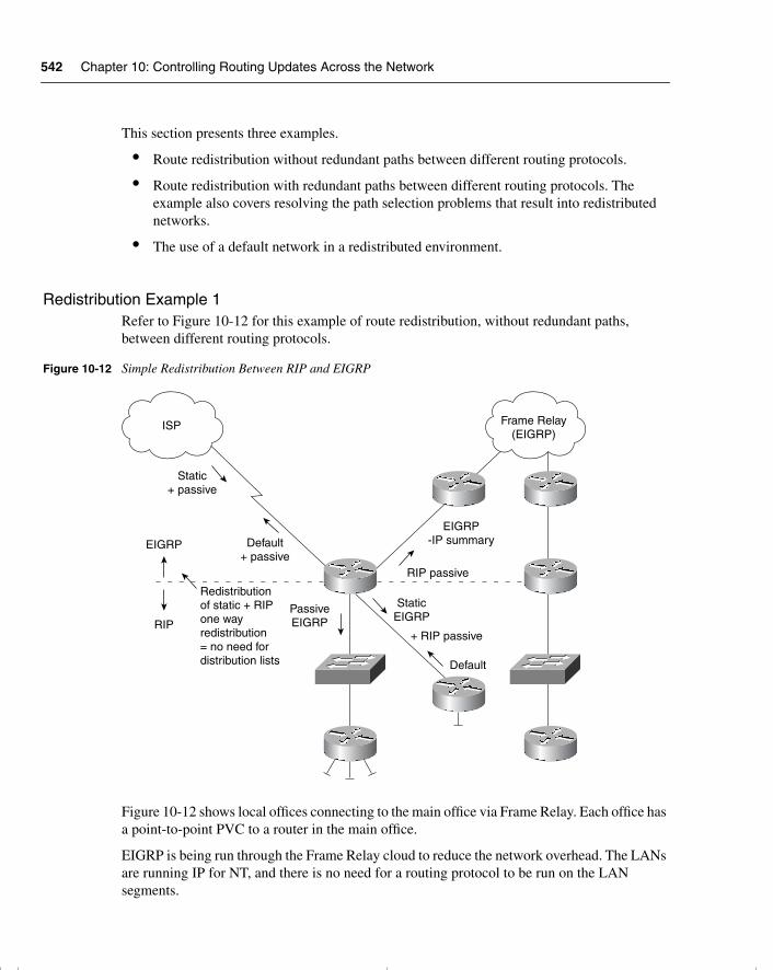
542 Chapter 10: Controlling Routing Updates Across the Network
This section presents three examples.
• Route redistribution without redundant paths between different routing protocols.
• Route redistribution with redundant paths between different routing protocols. The example also covers resolving the path selection problems that result into redistributed networks.
• The use of a default network in a redistributed environment.
Redistribution Example 1Refer to Figure 10-12 for this example of route redistribution, without redundant paths, between different routing protocols.
Figure 10-12 Simple Redistribution Between RIP and EIGRP
Figure 10-12 shows local offices connecting to the main office via Frame Relay. Each office has a point-to-point PVC to a router in the main office.
EIGRP is being run through the Frame Relay cloud to reduce the network overhead. The LANs are running IP for NT, and there is no need for a routing protocol to be run on the LAN segments.
EIGRP-IP summary
RIP passive
+ RIP passive
StaticEIGRP
Default
Static+ passive
Default+ passive
Redistributionof static + RIPone wayredistribution= no need fordistribution lists
PassiveEIGRP
ISP Frame Relay(EIGRP)
EIGRP
RIP
chpt_01.book Page 542 Thursday, December 21, 2000 6:22 PM
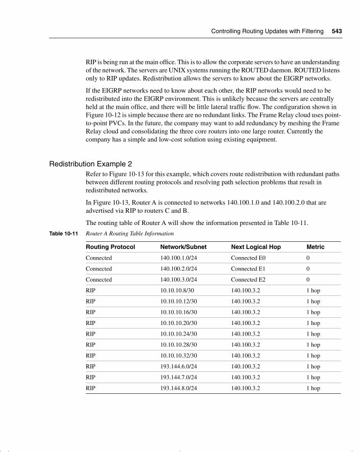
Controlling Routing Updates with Filtering 543
RIP is being run at the main office. This is to allow the corporate servers to have an understanding of the network. The servers are UNIX systems running the ROUTED daemon. ROUTED listens only to RIP updates. Redistribution allows the servers to know about the EIGRP networks.
If the EIGRP networks need to know about each other, the RIP networks would need to be redistributed into the EIGRP environment. This is unlikely because the servers are centrally held at the main office, and there will be little lateral traffic flow. The configuration shown in Figure 10-12 is simple because there are no redundant links. The Frame Relay cloud uses point-to-point PVCs. In the future, the company may want to add redundancy by meshing the Frame Relay cloud and consolidating the three core routers into one large router. Currently the company has a simple and low-cost solution using existing equipment.
Redistribution Example 2Refer to Figure 10-13 for this example, which covers route redistribution with redundant paths between different routing protocols and resolving path selection problems that result in redistributed networks.
In Figure 10-13, Router A is connected to networks 140.100.1.0 and 140.100.2.0 that are advertised via RIP to routers C and B.
The routing table of Router A will show the information presented in Table 10-11.
Table 10-11 Router A Routing Table Information
Routing Protocol Network/Subnet Next Logical Hop Metric
Connected 140.100.1.0/24 Connected E0 0
Connected 140.100.2.0/24 Connected E1 0
Connected 140.100.3.0/24 Connected E2 0
RIP 10.10.10.8/30 140.100.3.2 1 hop
RIP 10.10.10.12/30 140.100.3.2 1 hop
RIP 10.10.10.16/30 140.100.3.2 1 hop
RIP 10.10.10.20/30 140.100.3.2 1 hop
RIP 10.10.10.24/30 140.100.3.2 1 hop
RIP 10.10.10.28/30 140.100.3.2 1 hop
RIP 10.10.10.32/30 140.100.3.2 1 hop
RIP 193.144.6.0/24 140.100.3.2 1 hop
RIP 193.144.7.0/24 140.100.3.2 1 hop
RIP 193.144.8.0/24 140.100.3.2 1 hop
chpt_01.book Page 543 Thursday, December 21, 2000 6:22 PM
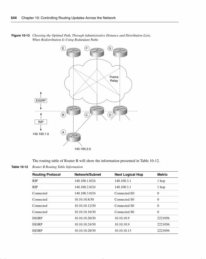
544 Chapter 10: Controlling Routing Updates Across the Network
Figure 10-13 Choosing the Optimal Path, Through Administrative Distance and Distribution Lists, When Redistribution Is Using Redundant Paths
The routing table of Router B will show the information presented in Table 10-12.
Table 10-12 Router B Routing Table Information
Routing Protocol Network/Subnet Next Logical Hop Metric
RIP 140.100.1.0/24 140.100.3.1 1 hop
RIP 140.100.2.0/24 140.100.3.1 1 hop
Connected 140.100.3.0/24 Connected E0 0
Connected 10.10.10.8/30 Connected S0 0
Connected 10.10.10.12/30 Connected S0 0
Connected 10.10.10.16/30 Connected S0 0
EIGRP 10.10.10.20/30 10.10.10.9 2221056
EIGRP 10.10.10.24/30 10.10.10.9 2221056
EIGRP 10.10.10.28/30 10.10.10.13 2221056
EIGRP
RIP
FrameRelay
E F G
B
A
C D
140.100.2.0
140.100.1.0
chpt_01.book Page 544 Thursday, December 21, 2000 6:22 PM
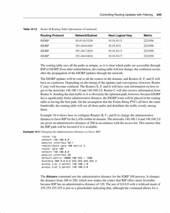
Controlling Routing Updates with Filtering 545
The routing table sees all the paths as unique, so it is clear which paths are accessible through RIP or EIGRP. Even after redistribution, the routing table will not change; the confusion occurs after the propagation of the EIGRP updates through the network.
The EIGRP updates will be sent to all the routers in the domain, and Routers E, F, and G will have no confusion. Depending on the timing of the updates and convergence, however, Router C may well become confused. The Routers E, F, and G will have sent information on how to get to the networks 140.100.1.0 and 140.100.2.0. Router C will also receive information from Router A. Sending the data traffic to A is obviously the optimum path, however; because EIGRP has a significantly better administrative distance, the EIGRP route will be placed in the routing table as having the best path. On the assumption that the Frame Relay PVCs all have the same bandwidth, the routing table will see all three paths and distribute the traffic evenly among them.
Example 10-4 shows how to configure Routers B, C, and D to change the administrative distance to favor RIP for the LANs within its domain. The networks 140.100.1.0 and 140.100.2.0 are given an administrative distance of 200 in accordance with the access list. This ensures that the RIP path will be favored if it is available.
The distance command sets the administrative distance for the IGRP 100 process. It changes the distance from 100 to 200, which now makes the routes that RIP offers more favorable because RIP has an administrative distance of 120. The use of 0.0.0.0 with a wildcard mask of 255.255.255.255 is just as a placeholder indicating that, although the command allows for a
EIGRP 10.10.10.32/30 10.10.10.13 2221056
EIGRP 193.144.6.0/24 10.10.10.9 2221056
EIGRP 193.144.7.0/24 10.10.10.13 2221056
EIGRP 193.144.8.0/24 10.10.10.17 2221056
Example 10-4 Changing the Administrative Distance to Favor RIP
router ripnetwork 140.100.0.0passive interface S0.1redistribute igrp 100 metric 3router igrp 100network 140.100.0.0passive interface E0default-metric 10000 100 255 1 1500distance 200 0.0.0.0 255.255.255.255 3access-list 3 permit 140.100.1.0access-list 3 permit 140.100.2.0
Table 10-12 Router B Routing Table Information (Continued)
Routing Protocol Network/Subnet Next Logical Hop Metric
chpt_01.book Page 545 Thursday, December 21, 2000 6:22 PM
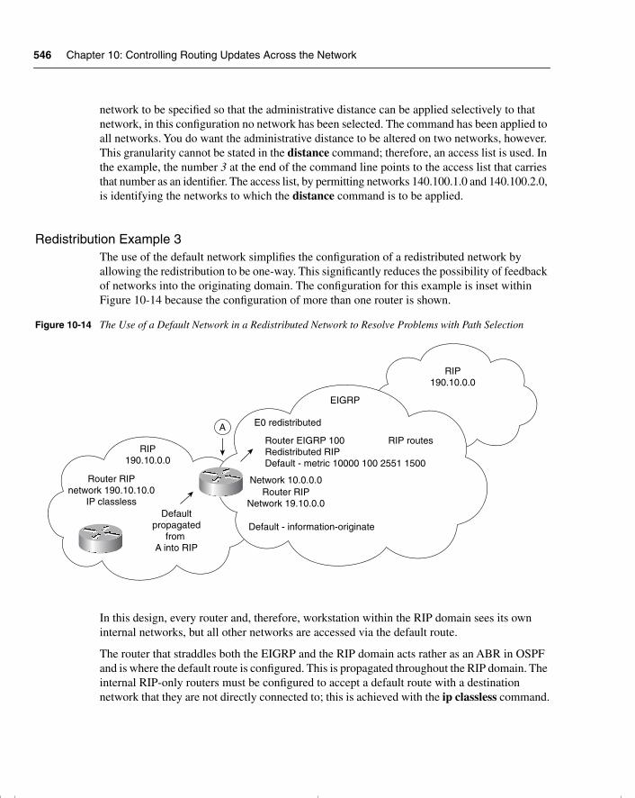
546 Chapter 10: Controlling Routing Updates Across the Network
network to be specified so that the administrative distance can be applied selectively to that network, in this configuration no network has been selected. The command has been applied to all networks. You do want the administrative distance to be altered on two networks, however. This granularity cannot be stated in the distance command; therefore, an access list is used. In the example, the number 3 at the end of the command line points to the access list that carries that number as an identifier. The access list, by permitting networks 140.100.1.0 and 140.100.2.0, is identifying the networks to which the distance command is to be applied.
Redistribution Example 3The use of the default network simplifies the configuration of a redistributed network by allowing the redistribution to be one-way. This significantly reduces the possibility of feedback of networks into the originating domain. The configuration for this example is inset within Figure 10-14 because the configuration of more than one router is shown.
Figure 10-14 The Use of a Default Network in a Redistributed Network to Resolve Problems with Path Selection
In this design, every router and, therefore, workstation within the RIP domain sees its own internal networks, but all other networks are accessed via the default route.
The router that straddles both the EIGRP and the RIP domain acts rather as an ABR in OSPF and is where the default route is configured. This is propagated throughout the RIP domain. The internal RIP-only routers must be configured to accept a default route with a destination network that they are not directly connected to; this is achieved with the ip classless command.
EIGRP
A
RIP190.10.0.0
RIP190.10.0.0
Router RIPnetwork 190.10.10.0
IP classlessDefault
propagatedfrom
A into RIP
E0 redistributed
Network 10.0.0.0Router RIP
Network 19.10.0.0
Default - information-originate
Router EIGRP 100Redistributed RIPDefault - metric 10000 100 2551 1500
RIP routes
chpt_01.book Page 546 Thursday, December 21, 2000 6:22 PM
Policy-Based Routing Using Route Maps 547
The redistribution on Router A can now be one-way. EIGRP needs to know all the networks in the RIP domain, but RIP, when configured with a default route, needs no understanding of the outside world. The RIP domain works in a similar fashion to a stub network in OSPF.
Policy-Based Routing Using Route MapsRoute maps are very similar to access lists. They both perform “if then” programming, in that they state criteria that is used to determine whether specific packets are to be permitted or denied.
The main difference is that the route map has the additional capability of adding a set criterion to the match criterion. In an access list, the match criterion is implicit; in a route map, it is a keyword. This means that if a packet is matched to the criterion given in the route map, some action can be taken to change the packet.
For example, an access list could state something similar to this logic: If the cupcake is lemon-flavored, keep it, but if it is has walnuts in it, throw it away.
Along the same lines, a route map could specify logic such as this: If it is a lemon-flavored cupcake, ice it with lemon butter frosting. If it has walnuts, then ice it with melted chocolate. If it has neither a lemon flavor nor walnuts, leave it alone. The route map is obviously more powerful because it can change the entity.
Now to make this simple example slightly more complex, to show the additional complexity of route maps, add a logical AND and a logical OR. For example, if it is a lemon-flavored cupcake AND it contains poppy seeds, ice it with lemon butter frosting. If it has walnuts OR it was baked today, then ice it with melted chocolate. If it has neither a lemon flavor nor walnuts, leave it alone.
The route map would look something like this:
route map cupcakes permit 10match lemon flavored poppy seedset add lemon butter frostingroute map cupcakes permit 15match walnutsmatch baked todayset melted chocolate frostingroute map cupcakes permit 20
For the mathematicians among you, this could be written as follows:
If {(a or b) match} then set cElse
If {(x and y) match} then set zElse
Set nothing
chpt_01.book Page 547 Thursday, December 21, 2000 6:22 PM
548 Chapter 10: Controlling Routing Updates Across the Network
Uses for Route MapsRoute maps can be used for the following purposes:
• To control redistribution
• To control and modify routing information
• To define policies in policy routing
Characteristics of Route MapsA route map has certain characteristics:
• A route map has a list of criteria, stated with the match statement.
• A route map can change packets or routes that are matched by using the set statement.
• A collection of route map statements that have the same route map name are considered one route map.
• Within a route map, each route map statement is numbered with sequence numbers and, therefore, can be edited individually.
• The statements in a route map correspond to the lines of an access list. Specifying the match conditions in a route map is similar to specifying the source and destination addresses and masks in an access list.
• The statements in the route map are compared to the route to see if there is a match. The statements are examined in turn from the top, as in an access list.
• The first match found for a route is applied, and the route map will not examine further.
• The match route map configuration commands are used to define the conditions to be checked.
• The set route map configuration commands are used to define the actions to be followed if there is a match.
• The single match statement may contain multiple conditions. At least one condition in the match statement must be true. This is a logical OR.
• A route map statement may contain multiple match statements. All match statements in the route map statement must be considered true for the route map statement to be considered matched. This is a logical AND.
• The sequence number is also used to specify the order in which conditions are checked. Thus, if there are two statements in a route map named BESTEST, one with sequence 5 and the other with sequence 15, sequence 5 is checked first. If there is no match for the conditions in sequence 5, then sequence 15 will be checked.
chpt_01.book Page 548 Thursday, December 21, 2000 6:22 PM
Policy-Based Routing Using Route Maps 549
• Like an access list, there is an implicit deny any at the end of a route map. The consequences of this deny depend on how the route map is being used. The specifics for policy-based routing are discussed later in this section.
The Route Map Command SyntaxThe route-map command is shown here and is followed by the route map configuration commands match and set.
route-map map-tag [[permit | deny] | [sequence-number]]
Table 10-13 describes the syntax options available for the route-map command.
Example 10-5 is very simple, but it clearly illustrates the functionality of the route map. Study the example in reference to Figure 10-15.
This route map examines all updates from RIP and redistributes those RIP routes with a hop count equal to 3 into OSPF. These routes will be redistributed into OSPF as external link-state advertisements with a metric cost of 6, a metric type of Type 1, and a tag equal to 1.
Table 10-13 The route-map Command Options
Command Description
map-tag This is the name of the route map. This name is used to reference the route map when using the redistribute router configuration command.
permit | deny (Optional) If the match criteria are met for this route map and permit is specified, the route is redistributed as defined by the set actions.
If the match criteria are not met and permit is specified, the next route map with the same map tag is tested.
If a route passes none of the match criteria for the set of route maps sharing the same name, it is not redistributed by that set because it hits the implicit deny any at the end of the list.
(Optional) If the match criteria are met for the route map and deny is specified, the route is not redistributed, and no further route maps sharing the same map tag name will be examined.
sequence-number (Optional) The sequence number indicates the position that a new route map will have in the list of route map statements already configured with the same name.
chpt_01.book Page 549 Thursday, December 21, 2000 6:22 PM
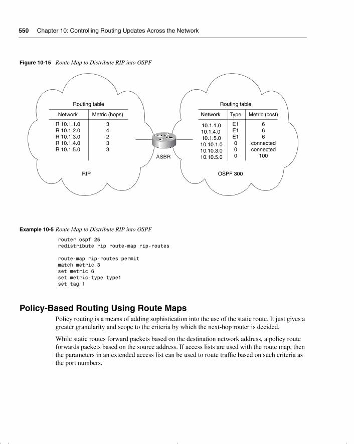
550 Chapter 10: Controlling Routing Updates Across the Network
Figure 10-15 Route Map to Distribute RIP into OSPF
Policy-Based Routing Using Route MapsPolicy routing is a means of adding sophistication into the use of the static route. It just gives a greater granularity and scope to the criteria by which the next-hop router is decided.
While static routes forward packets based on the destination network address, a policy route forwards packets based on the source address. If access lists are used with the route map, then the parameters in an extended access list can be used to route traffic based on such criteria as the port numbers.
Example 10-5 Route Map to Distribute RIP into OSPF
router ospf 25redistribute rip route-map rip-routes route-map rip-routes permitmatch metric 3set metric 6set metric-type type1set tag 1
ASBR
RIP OSPF 300
Routing table
Network Metric (hops)
R 10.1.1.0R 10.1.2.0R 10.1.3.0R 10.1.4.0R 10.1.5.0
34233
Routing table
Network Metric (cost)
10.1.1.010.1.4.0 10.1.5.0 10.10.1.0 10.10.3.0 10.10.5.0
666
connectedconnected
100
Type
E1E1E1000
chpt_01.book Page 550 Thursday, December 21, 2000 6:22 PM
Policy-Based Routing Using Route Maps 551
Characteristics of Policy RoutingThe rules that define policy routing are as follows:
• Traffic can be directed on either the source address or both the source and destination addresses.
• Policy routing affects only the routing of the router on which it is configured in determining the next hop in the path to the destination.
• Policy routing does not affect the destination of the packet.
• Policy routing does not allow traffic sent into another autonomous system to take a different path from the one that would have been chosen by that autonomous system.
• It is possible only to influence how traffic will get to a neighboring router.
• As policy routing examines the source address, it is configured on the inbound interface.
Route maps were introduced in Cisco IOS Release 11.0, allowing policies that defined different paths for different packets based on defined criteria.
Policy-based routing also provides a mechanism to mark packets with different types of service (TOS). This feature can be used in conjunction with Cisco IOS queuing techniques so that certain kinds of traffic can receive preferential service.
The Benefits of Policy Based RoutingThe benefits of implementing policy-based routing in networks include the following:
• Source-based transit provider selection—ISPs in particular use policy-based routing to make routing decisions based on the source address. This allows traffic belonging to different customers to be routed through different Internet connections, across the policy routers in accordance with whatever human policy needs to be adhered to.
• Quality of service (QoS)—By setting the precedence or TOS values in the IP packet headers in routers at the edge of the network, organizations can provide QoS. In this way, the traffic can be differentiated, and queuing mechanisms can be implemented to prioritize traffic based on the QoS in the core or backbone of the network. This improves network performance because the configuration is done only at the edge of the network.
• Cost savings—The bulk traffic generated by a specific activity can be diverted to use a higher-bandwidth, high-cost link for a short time. Meanwhile, interactive traffic is provided basic connectivity over a lower-bandwidth, low-cost link. For example, a dial-on-demand ISDN line might be raised in response to traffic to a finance server for file transfers selected by policy routing.
chpt_01.book Page 551 Thursday, December 21, 2000 6:22 PM
552 Chapter 10: Controlling Routing Updates Across the Network
• Load sharing—This allows the implementation of policies to distribute traffic among multiple paths based on the traffic characteristics. This does not detract from the dynamic load-sharing capabilities offered by destination-based routing that the Cisco IOS software has always supported.
Disadvantages of Policy RoutingSome things should be considered before arbitrarily deciding to implement policy routing:
• A backup path should be in place in case the defined next-hop router goes down. If there is no alternative defined, policy routing will default to dynamic routing decisions.
• Additional CPU is required to examine every source address to effect the defined policy.
• Extra configuration is required.
• The possibility exists that other traffic will be disrupted.
Criteria by Which Policy-Based Routes Are DeterminedInstead of routing by the destination address, policy-based routing allows network administrators to determine and implement routing policies to allow or deny paths based on the following:
• The identity of a particular end system
• The application being run
• The protocol in use
• The size of packets
How Policy-Based Routing Works Using Route MapsThe following list tells how policy-based routing works using route maps:
• Policy-based routing is applied to incoming packets. When a packet is received on an interface with policy-based routing enabled, it goes through this procedure.
• If there is a match and the action is to permit the route, then the route is policy-routed in accordance to the set command.
• If there is a match and the action is to deny the route, then the route is not policy-routed but is passed back to the forwarding engine.
• If there is no match and there is no configuration for what to do in this event, then the default is to deny the packet, which would return it to the routing process.
• To prevent packets that find no match from being returned to normal forwarding, specify a set statement to route the packets to interface null 0 as the last entry in the route map.
chpt_01.book Page 552 Thursday, December 21, 2000 6:22 PM
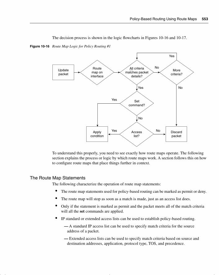
Policy-Based Routing Using Route Maps 553
The decision process is shown in the logic flowcharts in Figures 10-16 and 10-17.
Figure 10-16 Route Map Logic for Policy Routing #1
To understand this properly, you need to see exactly how route maps operate. The following section explains the process or logic by which route maps work. A section follows this on how to configure route maps that place things further in context.
The Route Map StatementsThe following characterize the operation of route map statements:
• The route map statements used for policy-based routing can be marked as permit or deny.
• The route map will stop as soon as a match is made, just as an access list does.
• Only if the statement is marked as permit and the packet meets all of the match criteria will all the set commands are applied.
• IP standard or extended access lists can be used to establish policy-based routing.
— A standard IP access list can be used to specify match criteria for the source address of a packet.
— Extended access lists can be used to specify match criteria based on source and destination addresses, application, protocol type, TOS, and precedence.
Updatepacket
Discardpacket
Applycondition
Routemap oninterface
No
Yes
Yes
Yes
No
No
No
All criteriamatches packet
details?
Setcommand?
Yes
Morecriteria?
Accesslist?
chpt_01.book Page 553 Thursday, December 21, 2000 6:22 PM
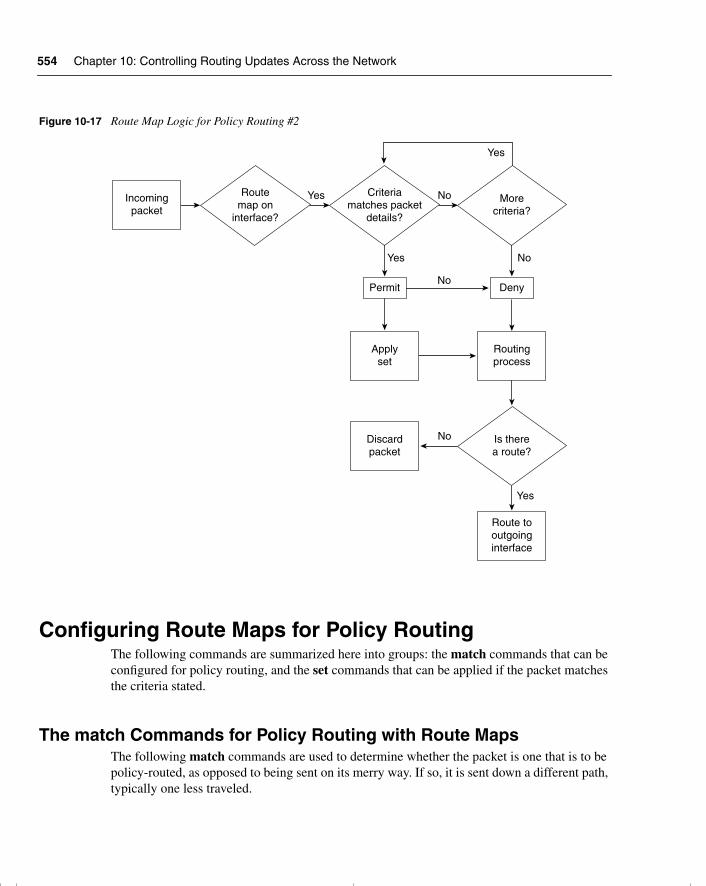
554 Chapter 10: Controlling Routing Updates Across the Network
Figure 10-17 Route Map Logic for Policy Routing #2
Configuring Route Maps for Policy RoutingThe following commands are summarized here into groups: the match commands that can be configured for policy routing, and the set commands that can be applied if the packet matches the criteria stated.
The match Commands for Policy Routing with Route MapsThe following match commands are used to determine whether the packet is one that is to be policy-routed, as opposed to being sent on its merry way. If so, it is sent down a different path, typically one less traveled.
YesIncomingpacket
Permit Deny
Routingprocess
Applyset
Discardpacket
Route tooutgoinginterface
Routemap on
interface?
No
No
Yes No
Criteriamatches packet
details?
Yes
Yes
Morecriteria?
Is therea route?
No
chpt_01.book Page 554 Thursday, December 21, 2000 6:22 PM
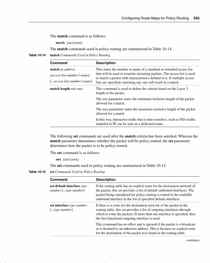
Configuring Route Maps for Policy Routing 555
The match command is as follows:
match {actions}
The match commands used in policy routing are summarized in Table 10-14.
The following set commands are used after the match criteria has been satisfied. Whereas the match parameter determines whether the packet will be policy-routed, the set parameter determines how the packet is to be policy-routed.
The set command is as follows:
set {actions}
The set commands used in policy routing are summarized in Table 10-15.
Table 10-14 match Commands Used in Policy Routing
Command Description
match ip address
[access-list-number | name]
[...access-list-number | name]
This states the number or name of a standard or extended access list that will be used to examine incoming packets. The access list is used to match a packet with characteristics defined in it. If multiple access lists are specified, matching any one will result in a match.
match length min max This command is used to define the criteria based on the Layer 3 length of the packet.
The min parameter states the minimum inclusive length of the packet allowed for a match.
The max parameter states the maximum inclusive length of the packet allowed for a match.
In this way, interactive traffic that is time-sensitive, such as SNA traffic tunneled in IP, can be sent on a dedicated route.
Table 10-15 set Commands Used in Policy Routing
Command Description
set default interface type number [...type number]
If the routing table has no explicit route for the destination network of the packet, this set provides a list of default outbound interfaces. The packet being considered for policy routing is routed to the available outbound interface in the list of specified default interfaces.
set interface type number [...type number]
If there is a route for the destination network of the packet in the routing table, this set provides a list of outgoing interfaces through which to route the packets. If more than one interface is specified, then the first functional outgoing interface is used.
This command has no effect and is ignored if the packet is a broadcast or is destined to an unknown address. This is because no explicit route for the destination of the packet was found in the routing table.
continues
chpt_01.book Page 555 Thursday, December 21, 2000 6:22 PM
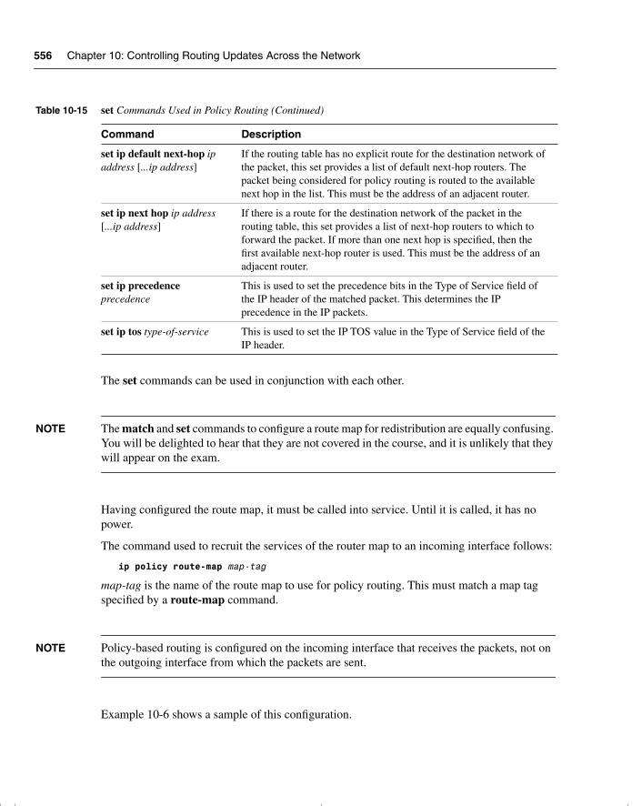
556 Chapter 10: Controlling Routing Updates Across the Network
The set commands can be used in conjunction with each other.
NOTE The match and set commands to configure a route map for redistribution are equally confusing. You will be delighted to hear that they are not covered in the course, and it is unlikely that they will appear on the exam.
Having configured the route map, it must be called into service. Until it is called, it has no power.
The command used to recruit the services of the router map to an incoming interface follows:
ip policy route-map map-tag
map-tag is the name of the route map to use for policy routing. This must match a map tag specified by a route-map command.
NOTE Policy-based routing is configured on the incoming interface that receives the packets, not on the outgoing interface from which the packets are sent.
Example 10-6 shows a sample of this configuration.
set ip default next-hop ip address [...ip address]
If the routing table has no explicit route for the destination network of the packet, this set provides a list of default next-hop routers. The packet being considered for policy routing is routed to the available next hop in the list. This must be the address of an adjacent router.
set ip next hop ip address [...ip address]
If there is a route for the destination network of the packet in the routing table, this set provides a list of next-hop routers to which to forward the packet. If more than one next hop is specified, then the first available next-hop router is used. This must be the address of an adjacent router.
set ip precedence precedence
This is used to set the precedence bits in the Type of Service field of the IP header of the matched packet. This determines the IP precedence in the IP packets.
set ip tos type-of-service This is used to set the IP TOS value in the Type of Service field of the IP header.
Table 10-15 set Commands Used in Policy Routing (Continued)
Command Description
chpt_01.book Page 556 Thursday, December 21, 2000 6:22 PM
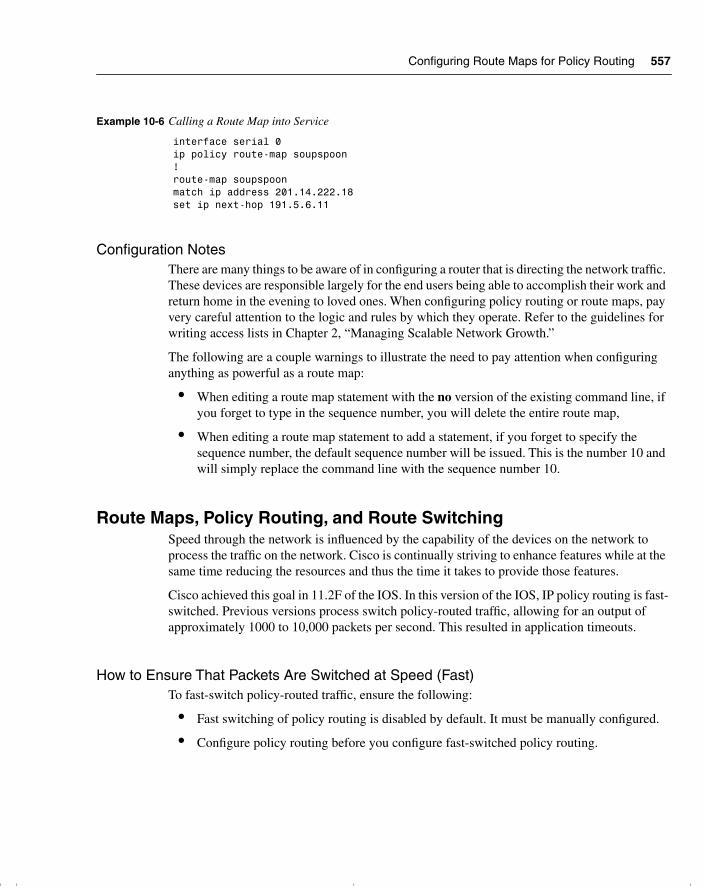
Configuring Route Maps for Policy Routing 557
Configuration NotesThere are many things to be aware of in configuring a router that is directing the network traffic. These devices are responsible largely for the end users being able to accomplish their work and return home in the evening to loved ones. When configuring policy routing or route maps, pay very careful attention to the logic and rules by which they operate. Refer to the guidelines for writing access lists in Chapter 2, “Managing Scalable Network Growth.”
The following are a couple warnings to illustrate the need to pay attention when configuring anything as powerful as a route map:
• When editing a route map statement with the no version of the existing command line, if you forget to type in the sequence number, you will delete the entire route map,
• When editing a route map statement to add a statement, if you forget to specify the sequence number, the default sequence number will be issued. This is the number 10 and will simply replace the command line with the sequence number 10.
Route Maps, Policy Routing, and Route SwitchingSpeed through the network is influenced by the capability of the devices on the network to process the traffic on the network. Cisco is continually striving to enhance features while at the same time reducing the resources and thus the time it takes to provide those features.
Cisco achieved this goal in 11.2F of the IOS. In this version of the IOS, IP policy routing is fast-switched. Previous versions process switch policy-routed traffic, allowing for an output of approximately 1000 to 10,000 packets per second. This resulted in application timeouts.
How to Ensure That Packets Are Switched at Speed (Fast)To fast-switch policy-routed traffic, ensure the following:
• Fast switching of policy routing is disabled by default. It must be manually configured.
• Configure policy routing before you configure fast-switched policy routing.
Example 10-6 Calling a Route Map into Service
interface serial 0ip policy route-map soupspoon!route-map soupspoonmatch ip address 201.14.222.18set ip next-hop 191.5.6.11
chpt_01.book Page 557 Thursday, December 21, 2000 6:22 PM
558 Chapter 10: Controlling Routing Updates Across the Network
• When policy routing is configured, turn on the fast switching with this interface command:
ip route-cache policy
• Fast-switched policy routing supports all of the match commands and most of the set commands, except for the following restrictions:
— The set ip default command is not supported.
— The set interface command is supported only over point-to-point links, unless a route-cache entry exists using the same interface specified in the set interface command in the route map. In addition, when process switching, the routing table is consulted to determine a path to the destination. During fast switching, the software does not make this check because fast switching is a cache of the process switch lookup. Instead, if the packet matches, the software blindly forwards the packet to the specified interface. This is a similar situation to the one described in reference to load balancing earlier.
Verifying, Maintaining, and Troubleshooting the Redistribution Implementation
The main key to maintaining and troubleshooting the redistribution within your network is to have a clear understanding of the network topology from both a physical and a logical perspective. The traffic flows—the peaks and lows in the traffic volume—are also important in truly understanding the connectivity issues within the network. From this vantage point, it is possible to interpret the output presented by the various tools available.
Most of the appropriate commands in tracking redistribution problems are ones that have been examined earlier. They include the following:
• show ip protocol
• show ip route
• show ip route routing protocol
• show ip eigrp neighbors
• show ip ospf database
In addition to these commands, the use of the such as trace and extended ping are also very useful.
traceroutetrace or traceroute are invoked from the exec privileged level. This shows the routers that a packet has passed through to reach its destination.
chpt_01.book Page 558 Thursday, December 21, 2000 6:22 PM
Verifying, Maintaining, and Troubleshooting the Redistribution Implementation 559
The extended traceroute test is called by entering the command without any destination. This results in the utility asking a series of questions, allowing you to change the defaults.
Extended pingTo check host reachability and network connectivity, use the ping (IP packet Internet groper function) privileged exec command. The extended ping utility is called by entering the command without any destination. This results in the utility asking a series of questions, allowing you to change the defaults.
Using trace and Extended ping
I do not use trace to determine the path taken, but rather to identify where there is a problem in the network. Where the trace utility fails indicates a good starting point for troubleshooting a complex network.
trace is not very reliable in reflecting the routing path because path changes are not shown. The extended ping command, however, is very useful because it announces every interface that it traverses. The limitation is the maximum hops that it can report, which is nine.
It is also possible to specify a source address in the trace or ping commands (as long as it is an interface on the router). This can be useful for testing certain types of access lists, route maps, and so on.
These commands are generic to TCP/IP troubleshooting.
Specific Commands for Monitoring Policy-Routing ConfigurationsTo monitor the policy-routing configuration, use the following exec commands described in Table 10-16.
Table 10-16 Commands to Monitor Policy Routing
Command Description
show ip policy Displays the route maps used for policy routing on the router’s interfaces.
show route-map Displays configured route maps.
debug ip policy Displays IP policy-routing packet activity. This command helps you determine what policy routing is doing. It displays information about whether a packet matches the criteria and, if so, the resulting routing information for the packet.
chpt_01.book Page 559 Thursday, December 21, 2000 6:22 PM
560 Chapter 10: Controlling Routing Updates Across the Network
NOTE Because the debug ip policy command generates a significant amount of output, use it only when traffic on the IP network is low so that other activity on the system is not adversely affected. This is true of all debug commands.
ConclusionAny limitation on the traffic flow in the network, particularly in terms of routing updates, will limit connectivity. Very careful analysis and design is therefore required.
Redistribution is an extremely powerful tool that allows the otherwise segmented portions of your organization to appear as one. To prevent the child’s game of rumors from taking over and destroying your network, some level of control is required as soon as redistribution is introduced to the network.
Policy routes are even more powerful, particularly with the capability to change the path of traffic based on specific criteria. Although this subject is advanced and, as such, has the feel of a loaded gun, it is crucial to the successful management of any large network. It is important to understand these subjects to pass the exam ahead, but it is more important to understand them in the light of how they can support your network.
chpt_01.book Page 560 Thursday, December 21, 2000 6:22 PM
Methods of Controlling Routing Updates 561
Foundation Summary
The “Foundation Summary” is a collection of quick reference information that provides a convenient review of many key concepts in this chapter. For those of you who already feel comfortable with the topics in this chapter, this summary will help you recall a few details. For those of you who just read this chapter, this review should help solidify some key facts. For any of you doing your final preparations before the exam, these tables and figures will be a convenient way to review the day before the exam.
Methods of Controlling Routing UpdatesVarious methods enable you to control the routing information sent between routers. These methods include the following:
• Passive interfaces—An interface that does not participate in the routing process. In RIP and IGRP, the process listens but will not send updates. In OSPF and EIGRP, the process neither listens nor sends updates because no neighbor relationship can form.
The interfaces that participate in the interior routing process are controlled by the interface configuration. During configuration, the routing process is instructed via the network command on which interfaces to use. Because most protocols express the networks at the major boundary, interfaces that have no reason to send this protocol’s updates propagate the data across the network. This is not only a waste of bandwidth, but in many cases, it also can lead to confusion.
• Default routes—A route used if there is no entry in the routing table for the destination network. If the lookup finds no entry for the desired network and no default network is configured, the packet is dropped.
If the routing process is denied the right to send updates, the downstream routers will have a limited understanding of the network. To resolve this, use default routes. Default routes reduce overhead, add simplicity, and can remove loops.
• Static routes—A route that is manually configured. It takes precedence over routes learned via a routing process.
If no routing process is configured, static routes may be configured to populate the routing table. This is not practical in a large network because the table cannot learn of changes in the network topology dynamically. In small environments or for stub networks, however, this is an excellent solution.
• The null interface—An imaginary interface that is defined as the next logical hop in a static route. All traffic destined for the remote network is carefully routed into a black hole.
chpt_01.book Page 561 Thursday, December 21, 2000 6:22 PM
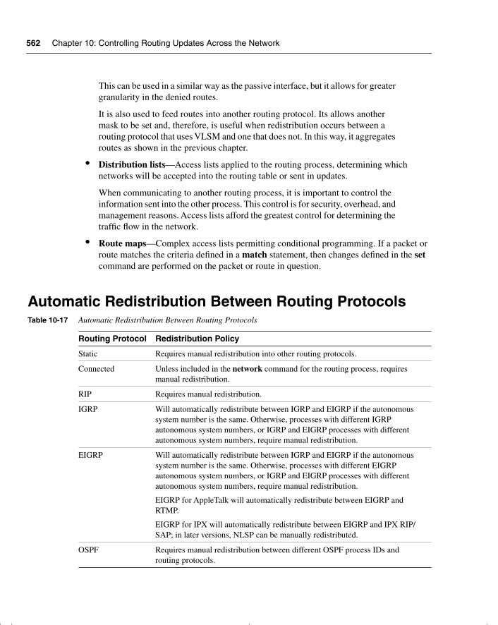
562 Chapter 10: Controlling Routing Updates Across the Network
This can be used in a similar way as the passive interface, but it allows for greater granularity in the denied routes.
It is also used to feed routes into another routing protocol. Its allows another mask to be set and, therefore, is useful when redistribution occurs between a routing protocol that uses VLSM and one that does not. In this way, it aggregates routes as shown in the previous chapter.
• Distribution lists—Access lists applied to the routing process, determining which networks will be accepted into the routing table or sent in updates.
When communicating to another routing process, it is important to control the information sent into the other process. This control is for security, overhead, and management reasons. Access lists afford the greatest control for determining the traffic flow in the network.
• Route maps—Complex access lists permitting conditional programming. If a packet or route matches the criteria defined in a match statement, then changes defined in the set command are performed on the packet or route in question.
Automatic Redistribution Between Routing ProtocolsTable 10-17 Automatic Redistribution Between Routing Protocols
Routing Protocol Redistribution Policy
Static Requires manual redistribution into other routing protocols.
Connected Unless included in the network command for the routing process, requires manual redistribution.
RIP Requires manual redistribution.
IGRP Will automatically redistribute between IGRP and EIGRP if the autonomous system number is the same. Otherwise, processes with different IGRP autonomous system numbers, or IGRP and EIGRP processes with different autonomous system numbers, require manual redistribution.
EIGRP Will automatically redistribute between IGRP and EIGRP if the autonomous system number is the same. Otherwise, processes with different EIGRP autonomous system numbers, or IGRP and EIGRP processes with different autonomous system numbers, require manual redistribution.
EIGRP for AppleTalk will automatically redistribute between EIGRP and RTMP.
EIGRP for IPX will automatically redistribute between EIGRP and IPX RIP/SAP; in later versions, NLSP can be manually redistributed.
OSPF Requires manual redistribution between different OSPF process IDs and routing protocols.
chpt_01.book Page 562 Thursday, December 21, 2000 6:22 PM
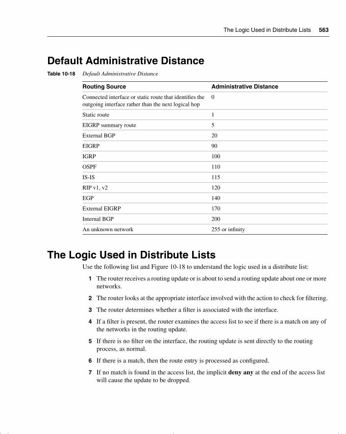
The Logic Used in Distribute Lists 563
Default Administrative Distance
The Logic Used in Distribute ListsUse the following list and Figure 10-18 to understand the logic used in a distribute list:
1 The router receives a routing update or is about to send a routing update about one or more networks.
2 The router looks at the appropriate interface involved with the action to check for filtering.
3 The router determines whether a filter is associated with the interface.
4 If a filter is present, the router examines the access list to see if there is a match on any of the networks in the routing update.
5 If there is no filter on the interface, the routing update is sent directly to the routing process, as normal.
6 If there is a match, then the route entry is processed as configured.
7 If no match is found in the access list, the implicit deny any at the end of the access list will cause the update to be dropped.
Table 10-18 Default Administrative Distance
Routing Source Administrative Distance
Connected interface or static route that identifies the outgoing interface rather than the next logical hop
0
Static route 1
EIGRP summary route 5
External BGP 20
EIGRP 90
IGRP 100
OSPF 110
IS-IS 115
RIP v1, v2 120
EGP 140
External EIGRP 170
Internal BGP 200
An unknown network 255 or infinity
chpt_01.book Page 563 Thursday, December 21, 2000 6:22 PM
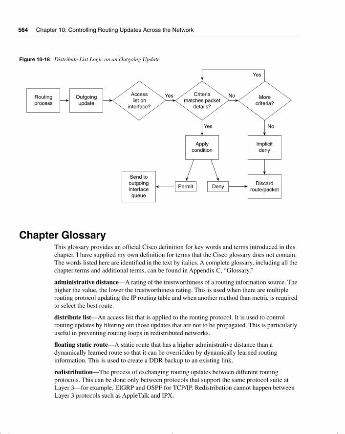
564 Chapter 10: Controlling Routing Updates Across the Network
Figure 10-18 Distribute List Logic on an Outgoing Update
Chapter GlossaryThis glossary provides an official Cisco definition for key words and terms introduced in this chapter. I have supplied my own definition for terms that the Cisco glossary does not contain. The words listed here are identified in the text by italics. A complete glossary, including all the chapter terms and additional terms, can be found in Appendix C, “Glossary.”
administrative distance—A rating of the trustworthiness of a routing information source. The higher the value, the lower the trustworthiness rating. This is used when there are multiple routing protocol updating the IP routing table and when another method than metric is required to select the best route.
distribute list—An access list that is applied to the routing protocol. It is used to control routing updates by filtering out those updates that are not to be propagated. This is particularly useful in preventing routing loops in redistributed networks.
floating static route—A static route that has a higher administrative distance than a dynamically learned route so that it can be overridden by dynamically learned routing information. This is used to create a DDR backup to an existing link.
redistribution—The process of exchanging routing updates between different routing protocols. This can be done only between protocols that support the same protocol suite at Layer 3—for example, EIGRP and OSPF for TCP/IP. Redistribution cannot happen between Layer 3 protocols such as AppleTalk and IPX.
YesOutgoingupdate
Routingprocess
Permit Deny
Implicitdeny
Discardroute/packet
Send tooutgoinginterfacequeue
Applycondition
Accesslist on
interface?
No
Yes No
Criteriamatches packet
details?
Yes
Morecriteria?
chpt_01.book Page 564 Thursday, December 21, 2000 6:22 PM

Chapter Glossary 565
seed metric—The metric that is given to a route when it enters the routing protocol. Most routes start with a metric of 0 because they first become known to the routing protocol to which they are directly connected. However, if they are redistributed into the routing protocol, there is no starting point from which to increment the route metric. Therefore, the default metric is configured to provide a seed metric for the redistributed routes.
ships in the night (SIN)—Routing that advocates the use of a completely separate and distinct routing protocol for each network protocol so that the multiple routing protocols essentially exist independently.
suboptimal path—A path that is not the best path. Sometimes a less desirable path is chosen.
chpt_01.book Page 565 Thursday, December 21, 2000 6:22 PM
566 Chapter 10: Controlling Routing Updates Across the Network
Q&A
The following questions test your understanding of the topics covered in this chapter. The final questions in this section repeat the opening “Do I Know This Already?” questions. These are repeated to enable you to test your progress. After you have answered the questions, find the answers in Appendix A. If you get an answer wrong, review the answer and ensure that you understand the reason for your mistake. If you are confused by the answer, refer to the appropriate text in the chapter to review the concepts.
1 State two of the methods that Cisco recommends for controlling routing traffic.
______________________________________________________________________
______________________________________________________________________
______________________________________________________________________
2 What is the administrative distance for RIP?
______________________________________________________________________
______________________________________________________________________
______________________________________________________________________
3 State two instances when you do not want routing information propagated.
______________________________________________________________________
______________________________________________________________________
______________________________________________________________________
4 In what instances will Enhanced IGRP automatically redistribute?
______________________________________________________________________
______________________________________________________________________
______________________________________________________________________
5 Which command is used to view the administrative distance on a route?
______________________________________________________________________
______________________________________________________________________
______________________________________________________________________
chpt_01.book Page 566 Thursday, December 21, 2000 6:22 PM
Q&A 567
6 When is redistribution required?
_______________________________________________________________________
_______________________________________________________________________
_______________________________________________________________________
7 Why does Cisco recommend that you not overlap routing protocols?
_______________________________________________________________________
_______________________________________________________________________
_______________________________________________________________________
8 Why would you want to prevent routing updates across an on-demand WAN link?
_______________________________________________________________________
_______________________________________________________________________
_______________________________________________________________________
9 What is the metric used for in a routing protocol?
_______________________________________________________________________
_______________________________________________________________________
_______________________________________________________________________
10 Explain the command match ip-address {access-list-number | name} [access-list number | name].
_______________________________________________________________________
_______________________________________________________________________
_______________________________________________________________________
11 Explain the command ip-route-cache policy.
_______________________________________________________________________
_______________________________________________________________________
_______________________________________________________________________
12 Give two reasons for using multiple routing protocols.
_______________________________________________________________________
_______________________________________________________________________
_______________________________________________________________________
chpt_01.book Page 567 Thursday, December 21, 2000 6:22 PM
568 Chapter 10: Controlling Routing Updates Across the Network
13 How many IP routing tables are there?
______________________________________________________________________
______________________________________________________________________
______________________________________________________________________
14 When implementing redistribution, state one possible problem that you might experience, and explain why it is a problem.
______________________________________________________________________
______________________________________________________________________
______________________________________________________________________
15 Which has a lower administrative distance, IGRP or OSPF?
______________________________________________________________________
______________________________________________________________________
______________________________________________________________________
16 What command is used to configure an outbound route filter?
______________________________________________________________________
______________________________________________________________________
______________________________________________________________________
17 What is a passive interface?
______________________________________________________________________
______________________________________________________________________
______________________________________________________________________
18 What is the purpose of administrative distance?
______________________________________________________________________
______________________________________________________________________
______________________________________________________________________
19 What is the concern of redistributing into a redundant network?
______________________________________________________________________
______________________________________________________________________
______________________________________________________________________
chpt_01.book Page 568 Thursday, December 21, 2000 6:22 PM
Q&A 569
20 What is a default network?
_______________________________________________________________________
_______________________________________________________________________
_______________________________________________________________________
21 Why is it necessary to configure a default metric when redistributing between routing protocols?
_______________________________________________________________________
_______________________________________________________________________
_______________________________________________________________________
22 Which command is used to modify the administrative distance of a route?
_______________________________________________________________________
_______________________________________________________________________
_______________________________________________________________________
23 What is the difference in processing for an inbound and an outbound route filter?
_______________________________________________________________________
_______________________________________________________________________
_______________________________________________________________________
24 State two benefits of using policy-based routing.
_______________________________________________________________________
_______________________________________________________________________
_______________________________________________________________________
25 How are matching routes modified in a route map?
_______________________________________________________________________
_______________________________________________________________________
_______________________________________________________________________
26 Explain the command set ip default-next-hop [ip-address...ip-address].
_______________________________________________________________________
_______________________________________________________________________
_______________________________________________________________________
chpt_01.book Page 569 Thursday, December 21, 2000 6:22 PM
570 Chapter 10: Controlling Routing Updates Across the Network
27 Which command displays route maps that are configured on interfaces?
______________________________________________________________________
______________________________________________________________________
______________________________________________________________________
chpt_01.book Page 570 Thursday, December 21, 2000 6:22 PM
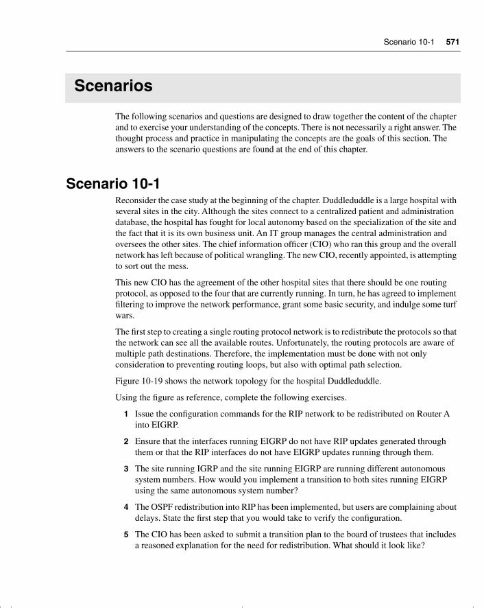
Scenario 10-1 571
Scenarios
The following scenarios and questions are designed to draw together the content of the chapter and to exercise your understanding of the concepts. There is not necessarily a right answer. The thought process and practice in manipulating the concepts are the goals of this section. The answers to the scenario questions are found at the end of this chapter.
Scenario 10-1Reconsider the case study at the beginning of the chapter. Duddleduddle is a large hospital with several sites in the city. Although the sites connect to a centralized patient and administration database, the hospital has fought for local autonomy based on the specialization of the site and the fact that it is its own business unit. An IT group manages the central administration and oversees the other sites. The chief information officer (CIO) who ran this group and the overall network has left because of political wrangling. The new CIO, recently appointed, is attempting to sort out the mess.
This new CIO has the agreement of the other hospital sites that there should be one routing protocol, as opposed to the four that are currently running. In turn, he has agreed to implement filtering to improve the network performance, grant some basic security, and indulge some turf wars.
The first step to creating a single routing protocol network is to redistribute the protocols so that the network can see all the available routes. Unfortunately, the routing protocols are aware of multiple path destinations. Therefore, the implementation must be done with not only consideration to preventing routing loops, but also with optimal path selection.
Figure 10-19 shows the network topology for the hospital Duddleduddle.
Using the figure as reference, complete the following exercises.
1 Issue the configuration commands for the RIP network to be redistributed on Router A into EIGRP.
2 Ensure that the interfaces running EIGRP do not have RIP updates generated through them or that the RIP interfaces do not have EIGRP updates running through them.
3 The site running IGRP and the site running EIGRP are running different autonomous system numbers. How would you implement a transition to both sites running EIGRP using the same autonomous system number?
4 The OSPF redistribution into RIP has been implemented, but users are complaining about delays. State the first step that you would take to verify the configuration.
5 The CIO has been asked to submit a transition plan to the board of trustees that includes a reasoned explanation for the need for redistribution. What should it look like?
chpt_01.book Page 571 Thursday, December 21, 2000 6:22 PM
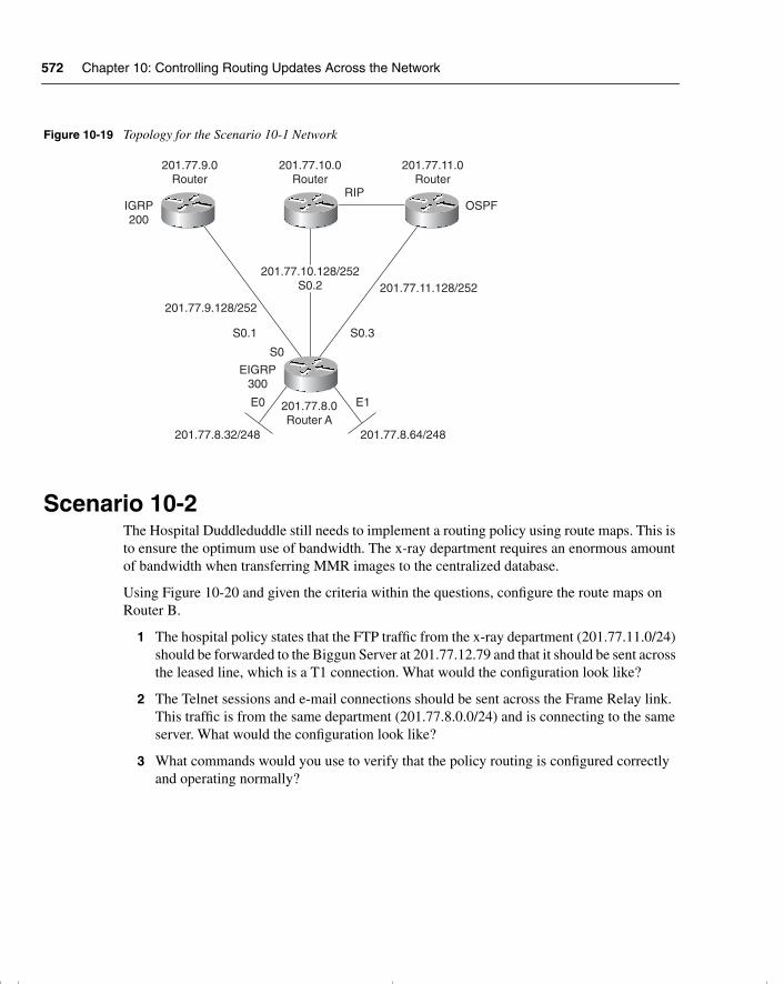
572 Chapter 10: Controlling Routing Updates Across the Network
Figure 10-19 Topology for the Scenario 10-1 Network
Scenario 10-2The Hospital Duddleduddle still needs to implement a routing policy using route maps. This is to ensure the optimum use of bandwidth. The x-ray department requires an enormous amount of bandwidth when transferring MMR images to the centralized database.
Using Figure 10-20 and given the criteria within the questions, configure the route maps on Router B.
1 The hospital policy states that the FTP traffic from the x-ray department (201.77.11.0/24) should be forwarded to the Biggun Server at 201.77.12.79 and that it should be sent across the leased line, which is a T1 connection. What would the configuration look like?
2 The Telnet sessions and e-mail connections should be sent across the Frame Relay link. This traffic is from the same department (201.77.8.0.0/24) and is connecting to the same server. What would the configuration look like?
3 What commands would you use to verify that the policy routing is configured correctly and operating normally?
201.77.9.0Router
201.77.10.0Router
201.77.11.0Router
201.77.8.0Router A
RIP
EIGRP300
S0
IGRP200
OSPF
201.77.11.128/252
E1
201.77.8.64/248
E0
201.77.8.32/248
201.77.9.128/252
S0.1
201.77.10.128/252S0.2
S0.3
chpt_01.book Page 572 Thursday, December 21, 2000 6:22 PM
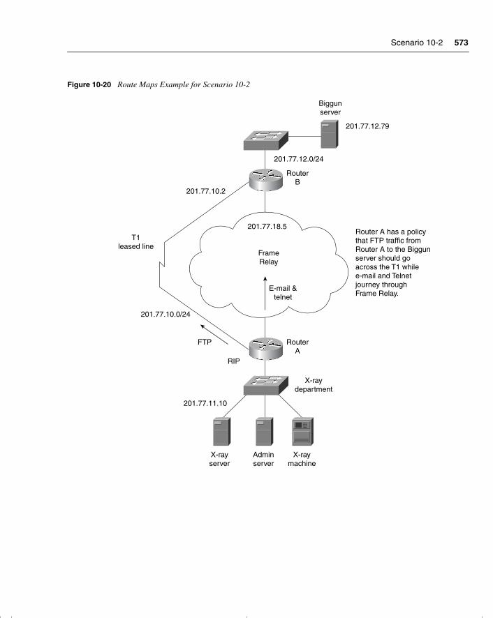
Scenario 10-2 573
Figure 10-20 Route Maps Example for Scenario 10-2
FrameRelay
E-mail &telnet
X-rayserver
Adminserver
X-raymachine
RouterA
RouterB
X-raydepartment
201.77.11.10
RIP
FTP
201.77.10.0/24
201.77.12.0/24
201.77.12.79
201.77.10.2
201.77.18.5
T1leased line
Biggunserver
Router A has a policythat FTP traffic fromRouter A to the Biggunserver should go across the T1 whilee-mail and Telnet journey throughFrame Relay.
chpt_01.book Page 573 Thursday, December 21, 2000 6:22 PM
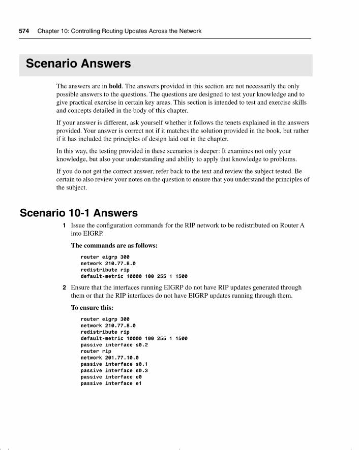
574 Chapter 10: Controlling Routing Updates Across the Network
Scenario Answers
The answers are in bold. The answers provided in this section are not necessarily the only possible answers to the questions. The questions are designed to test your knowledge and to give practical exercise in certain key areas. This section is intended to test and exercise skills and concepts detailed in the body of this chapter.
If your answer is different, ask yourself whether it follows the tenets explained in the answers provided. Your answer is correct not if it matches the solution provided in the book, but rather if it has included the principles of design laid out in the chapter.
In this way, the testing provided in these scenarios is deeper: It examines not only your knowledge, but also your understanding and ability to apply that knowledge to problems.
If you do not get the correct answer, refer back to the text and review the subject tested. Be certain to also review your notes on the question to ensure that you understand the principles of the subject.
Scenario 10-1 Answers1 Issue the configuration commands for the RIP network to be redistributed on Router A
into EIGRP.
The commands are as follows:
router eigrp 300network 210.77.8.0redistribute ripdefault-metric 10000 100 255 1 1500
2 Ensure that the interfaces running EIGRP do not have RIP updates generated through them or that the RIP interfaces do not have EIGRP updates running through them.
To ensure this:
router eigrp 300network 210.77.8.0redistribute ripdefault-metric 10000 100 255 1 1500passive interface s0.2router ripnetwork 201.77.10.0passive interface s0.1passive interface s0.3passive interface e0passive interface e1
chpt_01.book Page 574 Thursday, December 21, 2000 6:22 PM
Scenario 10-1 Answers 575
3 The site running IGRP and the site running EIGRP are running different autonomous system numbers. How would you implement a transition to both sites running EIGRP using the same autonomous system number?
There are several ways to transition from different autonomous systems to one autonomous system so that IGRP and EIGRP automatically redistribute. The methods include the following:
• Configuring redistribution at both sites and in a controlled manner, during down time switching all the routers in the IGRP site to the same autonomous system as that of EIGRP. Because the prevailing routing protocol is to be EIGRP, it makes sense that IGRP is the protocol to change the autonomous system number. When this is working, the same approach could be made to switch to EIGRP in the IGRP site.
• Another approach, and one favored by many, is to configure EIGRP with the same autonomous system number on all routers at the IGRP site. As part of the configuration, increase the administrative distance of EIGRP to be 200 so that none of the routes is acceptable to the routing process. Then during down time on the systems, cut over to the EIGRP process by changing its administrative distance back to the default of 90. This can be done by simply adding the word no in front of the existing command. The beauty of this plan is that everything can be put in place before the cutover; if problems are experienced, it is equally easy to reverse the command to return to the IGRP configuration.
4 The OSPF redistribution into RIP has been implemented, but users are complaining about delays. State the first step that you would take to verify the configuration.
The first step is to issue the following commands:
• show ip route—To ensure that each routing process sees the appropriate paths. A routing loop might be visible here.
• extended ping—To see the path that is taken to the remote locations. A routing loop could be detected.
• show ip protocols—To see how RIP and OSPF are being redistributed, what the default metrics are, and whether there any distribute lists are impeding the flow of updates.
• show ip ospf database—To ensure that all the routes are in place. Again, errors leading to a routing loop could be detected here.
• show ip ospf neighbor—To ensure that OSPF can still see the adjacent routers.
chpt_01.book Page 575 Thursday, December 21, 2000 6:22 PM
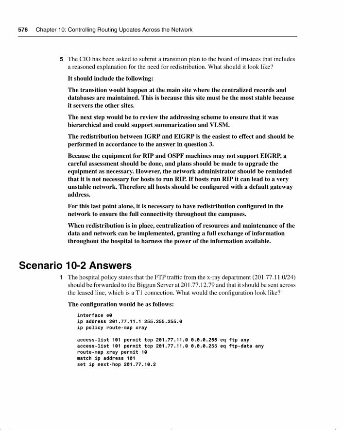
576 Chapter 10: Controlling Routing Updates Across the Network
5 The CIO has been asked to submit a transition plan to the board of trustees that includes a reasoned explanation for the need for redistribution. What should it look like?
It should include the following:
The transition would happen at the main site where the centralized records and databases are maintained. This is because this site must be the most stable because it servers the other sites.
The next step would be to review the addressing scheme to ensure that it was hierarchical and could support summarization and VLSM.
The redistribution between IGRP and EIGRP is the easiest to effect and should be performed in accordance to the answer in question 3.
Because the equipment for RIP and OSPF machines may not support EIGRP, a careful assessment should be done, and plans should be made to upgrade the equipment as necessary. However, the network administrator should be reminded that it is not necessary for hosts to run RIP. If hosts run RIP it can lead to a very unstable network. Therefore all hosts should be configured with a default gateway address.
For this last point alone, it is necessary to have redistribution configured in the network to ensure the full connectivity throughout the campuses.
When redistribution is in place, centralization of resources and maintenance of the data and network can be implemented, granting a full exchange of information throughout the hospital to harness the power of the information available.
Scenario 10-2 Answers1 The hospital policy states that the FTP traffic from the x-ray department (201.77.11.0/24)
should be forwarded to the Biggun Server at 201.77.12.79 and that it should be sent across the leased line, which is a T1 connection. What would the configuration look like?
The configuration would be as follows:
interface e0ip address 201.77.11.1 255.255.255.0ip policy route-map xray
access-list 101 permit tcp 201.77.11.0 0.0.0.255 eq ftp anyaccess-list 101 permit tcp 201.77.11.0 0.0.0.255 eq ftp-data anyroute-map xray permit 10match ip address 101set ip next-hop 201.77.10.2
chpt_01.book Page 576 Thursday, December 21, 2000 6:22 PM
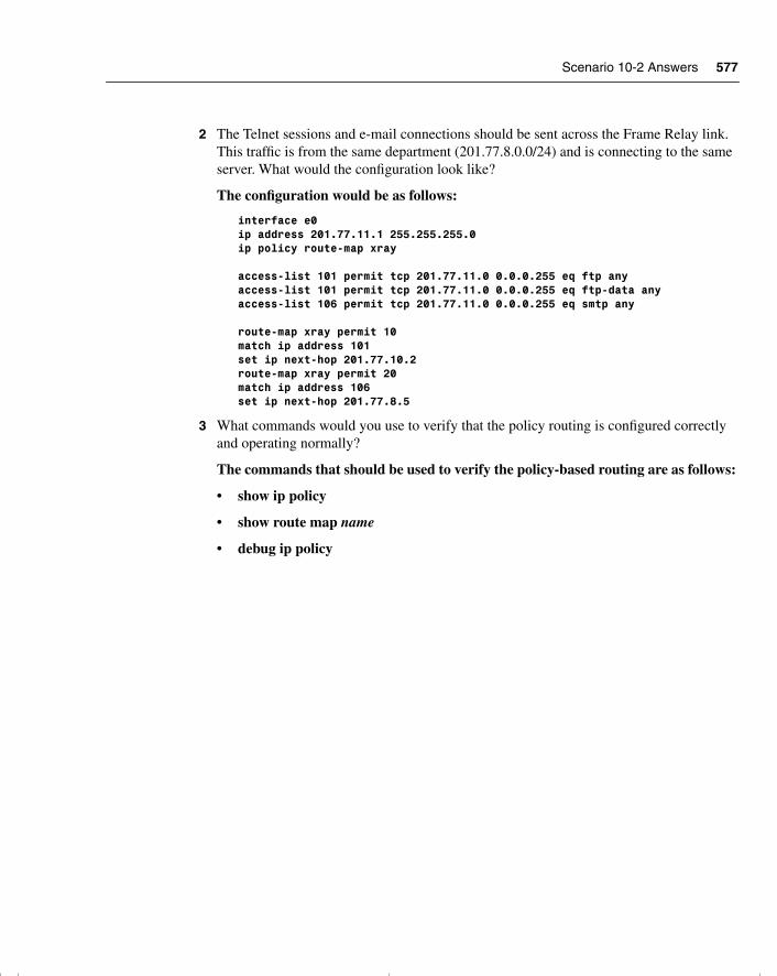
Scenario 10-2 Answers 577
2 The Telnet sessions and e-mail connections should be sent across the Frame Relay link. This traffic is from the same department (201.77.8.0.0/24) and is connecting to the same server. What would the configuration look like?
The configuration would be as follows:
interface e0ip address 201.77.11.1 255.255.255.0ip policy route-map xray
access-list 101 permit tcp 201.77.11.0 0.0.0.255 eq ftp anyaccess-list 101 permit tcp 201.77.11.0 0.0.0.255 eq ftp-data anyaccess-list 106 permit tcp 201.77.11.0 0.0.0.255 eq smtp any
route-map xray permit 10match ip address 101set ip next-hop 201.77.10.2route-map xray permit 20match ip address 106set ip next-hop 201.77.8.5
3 What commands would you use to verify that the policy routing is configured correctly and operating normally?
The commands that should be used to verify the policy-based routing are as follows:
• show ip policy
• show route map name
• debug ip policy
chpt_01.book Page 577 Thursday, December 21, 2000 6:22 PM

chpt_01.book Page 578 Thursday, December 21, 2000 6:22 PM
C H A P T E R 11
Scenarios for Final Preparation
This chapter is designed to assist you in final preparation for the Routing exam by providing additional practice with the core topics of the exam. These exercises and tasks require a broad perspective, which means that you will need to draw on knowledge that you acquired in each of Chapters 2 through 10. This chapter also focuses on configuration and verification commands. These scenarios are designed with the following assumptions in mind:
• You might forget many details of a particular technology by the time you have completed your study of the other chapters. These scenarios cover the entire breadth of topics to remind you about many of these details.
• The scenarios not only cover the entire breadth of the course, but they also put the topics in context. This makes it easier to comprehend each subject because it is no longer presented in a vacuum.
• The ability to apply knowledge in different contexts proves an understanding that goes way beyond simple learning. The mind is exercised outside the scope of the individual facts that are presented, which makes those facts much easier to remember.
• This application of the technology is a good preparation not only for the Routing exam, but also for day-to-day administrative tasks.
• Your understanding of the concepts at this point in your study is complete; practice and repetition is useful so that you can answer quickly and confidently on the exam.
Further Study for Final PreparationThis chapter is not the only chapter that you should use when doing your final preparation for the Routing exam. Not all the subjects in the exam are covered in this chapter. Here is a brief list of the study options provided by this book, beyond the core chapters and this scenarios chapter:
• All prechapter quiz and chapter-ending questions, with answers, are in Appendix A, “Answers to Quiz Questions.” These conveniently located questions can be read and reviewed quickly, with explanations.
• The CD-ROM contains practice exam questions that you can use to take an overall sample exam or test yourself on specific topics. The CD-ROM also contains an electronic version of the book as well as supplemental material.
chpt_01.book Page 579 Thursday, December 21, 2000 6:22 PM
580 Chapter 11: Scenarios for Final Preparation
• Each core chapter has a “Foundation Summary” section near the end that contains concise tables and information for final review.
• Where appropriate, each chapter has a glossary for the terms introduced in that chapter. The chapter glossaries and Appendix C, “Glossary,” are also good study aids.
How to Best Use This Chapter This chapter includes two types of scenarios. The chapter is divided into two sections:
• Scenarios—Standard questions based on a presented situation. These are Scenarios 11-1, 11-2, and 11-3. The answers to these scenarios follow the three scenarios.
• Three-part scenarios—More complicated scenarios that require planning, configuration, and verification. These are Scenarios 11-4 and 11-5. The solutions to the three-part scenarios are contained within each scenario.
The focus of these scenarios is easily forgotten items. The first such items are the show and debug commands. Their options are often ignored, mainly because you can get online help about the correct option easily when using the Cisco CLI. However, questions about the exact command options used to see a particular piece of information are scattered throughout the exam. Take care to review the output of the commands in these scenarios.
Another focus of this chapter is a review of command-line tricks and acronym trivia. Like it or not, part of the preparation involves memorization; hopefully, these reminders will help you answer a question or two on the exam.
Finally, this chapter contains more configurations for almost all options already covered in the book. If you can configure these options without online help, you should feel confident that you can choose the correct command from a list.
chpt_01.book Page 580 Thursday, December 21, 2000 6:22 PM
Scenario 11-1 581
Scenarios
The following case studies and questions are designed to draw together the content of the chapters and to exercise your understanding of the concepts. There is not necessarily a right answer. The thought process and practice in manipulating the concepts are the goals of this section. The answers to these scenarios immediately follow Scenario 11-3.
Scenario 11-1The last network administrator of your company left abruptly. You were recently hired to the position and cannot find any documentation on the network. Using a network-management tool, you now have a topology map of the network.
Refer to Figure 11-1 and answer the questions that follow.
1 Offer some reasons why the routing protocol EIGRP has recently been implemented in the network, and give the reasons for its deployment in that particular area of the network.
2 The ISP has decided that the company should set a default route into its domain. Write out the commands that would configure the default route.
3 Is the router connecting to the ISP the only router that needs configuration? If this is the case, explain the reasons for your decision. If other routers need configuration, write out the commands required, and explain why they are needed and where they would be applied.
4 The ISP router connecting into the company network will need static route(s) configured. Write out the commands to configure the router.
5 Will these routes need to be redistributed into the ISP domain? If the answer is yes, explain the reason for your decision, and then write out the configuration commands. If the answer is no, explain the reasons for your decision.
6 Are filters required in this design? If so, state why, describe the type of filters required, and tell how and where they would be applied.
7 It has been suggested that Enhanced IGRP should be configured using summarization. If this plan were to be implemented, on which routers would it be configured, and why?
chpt_01.book Page 581 Thursday, December 21, 2000 6:22 PM
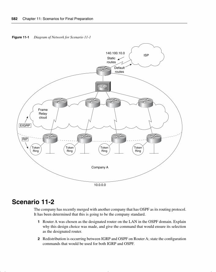
582 Chapter 11: Scenarios for Final Preparation
Figure 11-1 Diagram of Network for Scenario 11-1
Scenario 11-2The company has recently merged with another company that has OSPF as its routing protocol. It has been determined that this is going to be the company standard.
1 Router A was chosen as the designated router on the LAN in the OSPF domain. Explain why this design choice was made, and give the command that would ensure its selection as the designated router.
2 Redistribution is occurring between IGRP and OSPF on Router A; state the configuration commands that would be used for both IGRP and OSPF.
TokenRing
TokenRing
TokenRing
TokenRing
ISP
EIGRP
RIP
Company A
10.0.0.0
FrameRelaycloud
140.100.10.0
Staticroutes
Defaultroutes
chpt_01.book Page 582 Thursday, December 21, 2000 6:22 PM
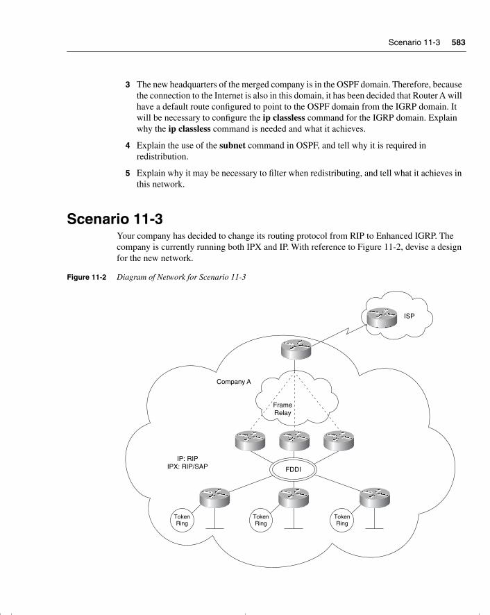
Scenario 11-3 583
3 The new headquarters of the merged company is in the OSPF domain. Therefore, because the connection to the Internet is also in this domain, it has been decided that Router A will have a default route configured to point to the OSPF domain from the IGRP domain. It will be necessary to configure the ip classless command for the IGRP domain. Explain why the ip classless command is needed and what it achieves.
4 Explain the use of the subnet command in OSPF, and tell why it is required in redistribution.
5 Explain why it may be necessary to filter when redistributing, and tell what it achieves in this network.
Scenario 11-3Your company has decided to change its routing protocol from RIP to Enhanced IGRP. The company is currently running both IPX and IP. With reference to Figure 11-2, devise a design for the new network.
Figure 11-2 Diagram of Network for Scenario 11-3
ISP
TokenRing
Company A
TokenRing
TokenRing
FrameRelay
IP: RIPIPX: RIP/SAP FDDI
chpt_01.book Page 583 Thursday, December 21, 2000 6:22 PM
584 Chapter 11: Scenarios for Final Preparation
Ensure that you include the following:
1 Create a transition plan, showing how the final design will be implemented.
2 If the transition plan requires redistribution, indicate these points on the diagram and provide the configuration commands.
3 The company has also decided to connect to the Internet using Enhanced IGRP, which the ISP providing the Internet connectivity has agreed upon. Is any redistribution required? Give reasons for your answers.
4 Explain the neighbors that you see on the LAN segment and the path selection on Router B.
5 Create a diagram that shows the final network design, with configuration commands for Enhanced IGRP.
6 Write out the configuration commands for Router B.
chpt_01.book Page 584 Thursday, December 21, 2000 6:22 PM
Scenario 11-1 Answers 585
Scenario Answers
The answers are in bold. The answers provided in this section are not necessarily the only possible answers to the questions. The questions are designed to test your knowledge and to give practical exercise in certain key areas. This section is intended to test and exercise skills and concepts detailed in the body of this chapter.
If your answer is different, ask yourself whether it follows the tenets explained in the answers provided. Your answer is correct not if it matches the solution provided in the book, but rather if it has included the principles of design laid out in the chapter.
In this way, the testing provided in these scenarios is deeper: It examines not only your knowledge, but also your understanding and ability to apply that knowledge to problems.
If you do not get the correct answer, refer back to the text and review the subject tested. Be certain to also review your notes on the question to ensure that you understand the principles of the subject.
Scenario 11-1 Answers1 Offer some reasons why the routing protocol Enhanced IGRP has recently been
implemented in the network, and give the reasons for its deployment in that particular area of the network.
Enhanced IGRP is being run across the Frame Relay WAN in areas where there are no client or server workstations. The network routers are all Cisco devices, which understand Enhanced IGRP.
Using Enhanced IGRP is far more efficient on a WAN because incremental updates can be sent across the limited bandwidth. In particular, if either AppleTalk or IPX is running at the access level, the routing updates can be sent in Enhanced IGRP, which gives far more control and flexibility because it is a new, more sophisticated, proprietary routing protocol.
2 The ISP has decided that the company should set a default route into its domain. Write out the commands that would configure the default route.
The configuration commands to establish a default route from the company’s network to the ISP domain are as follows:
Router(config)# router eigrp 100Router(config-router)# network 10.0.0.0Router(config-router)# network 140.100.10.0Router(config)# ip default network 140.100.0.0
The network command is also required for EIGRP to propagate the network in the updates.
chpt_01.book Page 585 Thursday, December 21, 2000 6:22 PM
586 Chapter 11: Scenarios for Final Preparation
3 Is the router connecting to the ISP the only router that needs configuration? If this is the case, explain the reasons for your decision. If other routers need configuration, write out the commands required, explain why they are needed, and tell where they would be applied.
The router connecting to the ISP is the only router that needs to be configured. The default route will be propagated to all the other EIGRP routers automatically. Although default routes redistributed into a RIP environment require that the ip classless command be configured, this is for routers that are downstream from the router that is dealing with the redistribution. Because the routers at the redistribution points will have routes redistributed into them by Enhanced IGRP, they will have no problem in the lookup.
4 The ISP router connecting into the company network will need static route(s) configured. Write out the commands to configure the router.
The configuration commands to establish static routes from the ISP domain into the company’s network are as follows:
Router(config)# ip route 140.100.0.0 255.255.0.0 140.100.60.3Router(config)# ip route 200.10.20.0 255.255.255.0 140.100.60.3Router(config)# ip route 199.56.10.0 255.255.255.0 140.100.60.3Router(config)# ip route 222.22.10.0 255.255.255.0 140.100.60.3
5 Will these routes need to be redistributed into the ISP domain? If the answer is yes, explain the reason for your decision, and then write out the configuration commands. If the answer is no, explain the reasons for your decision.
The static commands will need to be redistributed into the ISP domain. Static routes are not redistributed automatically. Static routes configured with the outgoing interface as opposed to the next-hop address are considered by the router to be directly connected.
The commands for redistribution of static routes are as follows:
Router(config)# Router EIGRP 100Router(config)# redistribute staticRouter(config)# default-metric 10000 100 255 1 1500
6 Are filters required in this design? If so, state why, describe the type of filters required, and tell how and where they would be applied
Because there are no redundant paths in the redistribution between protocols, no filters are required in the configuration of the routers. There will be no feedback between the protocols.
chpt_01.book Page 586 Thursday, December 21, 2000 6:22 PM
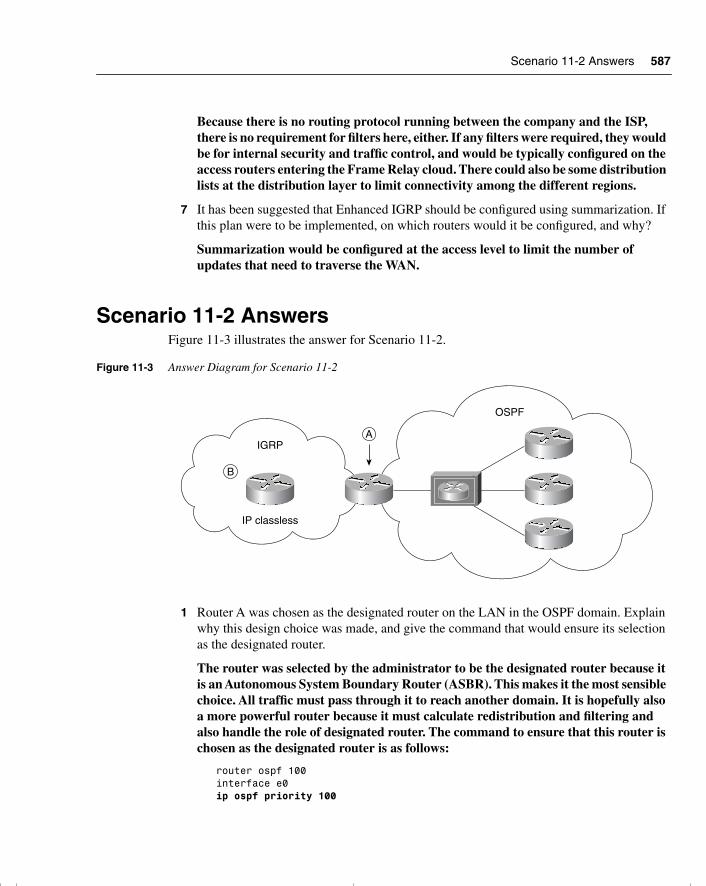
Scenario 11-2 Answers 587
Because there is no routing protocol running between the company and the ISP, there is no requirement for filters here, either. If any filters were required, they would be for internal security and traffic control, and would be typically configured on the access routers entering the Frame Relay cloud. There could also be some distribution lists at the distribution layer to limit connectivity among the different regions.
7 It has been suggested that Enhanced IGRP should be configured using summarization. If this plan were to be implemented, on which routers would it be configured, and why?
Summarization would be configured at the access level to limit the number of updates that need to traverse the WAN.
Scenario 11-2 AnswersFigure 11-3 illustrates the answer for Scenario 11-2.
Figure 11-3 Answer Diagram for Scenario 11-2
1 Router A was chosen as the designated router on the LAN in the OSPF domain. Explain why this design choice was made, and give the command that would ensure its selection as the designated router.
The router was selected by the administrator to be the designated router because it is an Autonomous System Boundary Router (ASBR). This makes it the most sensible choice. All traffic must pass through it to reach another domain. It is hopefully also a more powerful router because it must calculate redistribution and filtering and also handle the role of designated router. The command to ensure that this router is chosen as the designated router is as follows:
router ospf 100interface e0ip ospf priority 100
OSPF
IP classless
IGRP
B
A
chpt_01.book Page 587 Thursday, December 21, 2000 6:22 PM
588 Chapter 11: Scenarios for Final Preparation
The designated router will have been selected manually by using this priority command or by configuring the router with the highest OSPF ID. This is achieved by allocating a loopback address.
2 Redistribution is occurring between IGRP and OSPF on Router A; state the configuration commands that would be used for both IGRP and OSPF.
The configuration commands for redistributing OSPF into IGRP and IGRP back into OSPF follow:
router igrp 100passive int e0network 201.100.10.0redistribute ospf 100 metric 10000 100 255 1 1500
router ospf 100passive interface e1network 144.250.0.0 0.0.255.255 area 0redistribute igrp 100 metric 30 metric-type 1 subnets
The use of the passive interface is unnecessary because the routing processes do not use the same Internet number. These commands will allow full connectivity between the two domains.
3 The new headquarters of the merged company is in the OSPF domain. Therefore, because the connection to the Internet is also in this domain, it has been decided that Router A will have a default route configured to point to the OSPF domain from the IGRP domain. It will be necessary to configure the ip classless command for the IGRP domain. Explain why the ip classless command is needed, and tell what it achieves.
The ip classless command is required in a classful routing protocol that is doing a lookup in a routing table that does not contain the route because redistribution has not propagated the route to this router. So, when a default route is redistributed into a classful routing domain, the downstream routers cannot see the network that they should forward to. This command solves that problem.
4 Explain the use of the subnet command in OSPF, and tell why it is required in redistribution.
The subnet command is used to propagate subnetworks into the OSPF domain instead of propagating the larger classful address obtained from the InterNIC.
5 Explain why it may be necessary to filter when redistributing, and tell what it achieves in this network.
The filter prevents feedback from OSPF into IGRP, and vice versa. This avoids routing loops.
chpt_01.book Page 588 Thursday, December 21, 2000 6:22 PM
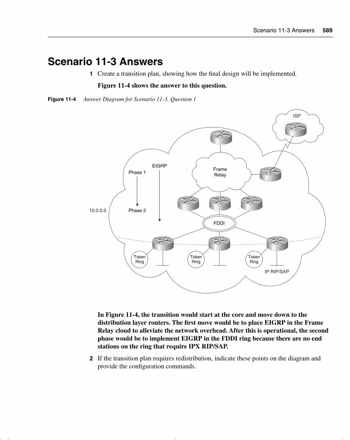
Scenario 11-3 Answers 589
Scenario 11-3 Answers1 Create a transition plan, showing how the final design will be implemented.
Figure 11-4 shows the answer to this question.
Figure 11-4 Answer Diagram for Scenario 11-3, Question 1
In Figure 11-4, the transition would start at the core and move down to the distribution layer routers. The first move would be to place EIGRP in the Frame Relay cloud to alleviate the network overhead. After this is operational, the second phase would be to implement EIGRP in the FDDI ring because there are no end stations on the ring that require IPX RIP/SAP.
2 If the transition plan requires redistribution, indicate these points on the diagram and provide the configuration commands.
TokenRing
TokenRing
TokenRing
FDDI
ISP
IP RIP/SAP
10.0.0.0
EIGRPPhase 1
Phase 2
FrameRelay
chpt_01.book Page 589 Thursday, December 21, 2000 6:22 PM
590 Chapter 11: Scenarios for Final Preparation
The configuration commands that provide for the redistribution between the different routing protocols are as follows:
Router(config)# router ripRouter(config-router)#network 10.0.0.0Router(config-router)#passive int E0Router(config-router)#redistribute eigrp 100Router(config-router)# default-metric 3Router(config)# router eigrp 100Router(config-router)#network 10.0.0.0Router(config-router)#passive int E1Router(config-router)#passive int Token 0Router(config-router)#redistribute ripRouter(config-router)# default-metric 10000 100 255 1 1500
3 The company has also decided to connect to the Internet using Enhanced IGRP, which the ISP providing the Internet connectivity has agreed upon. Is any redistribution required? Give reasons for your answers.
If the ISP is in the same autonomous system as the company, no redistribution is required between the company and the ISP. Within the ISP domain, however, it is likely that the router connecting to the company in question is the only router that is a part of the autonomous system of the company. This is for security reasons. Therefore, some form of redistribution probably will be required in the ISP domain.
4 Explain the neighbors that you see on the LAN segment and the path selection on Router B.
The neighbors that are seen on the LAN segment are all the routers that share the physical medium. Router B chose the path as a successor because it provided the shortest path to the networks stated.
5 Create a diagram that shows the final network design, with configuration commands for Enhanced IGRP.
Figure 11-5 shows the answer.
In Figure 11-5, ip summary-address may be configured where appropriate at the distribution layer (the routers entering the Frame Relay cloud).
chpt_01.book Page 590 Thursday, December 21, 2000 6:22 PM
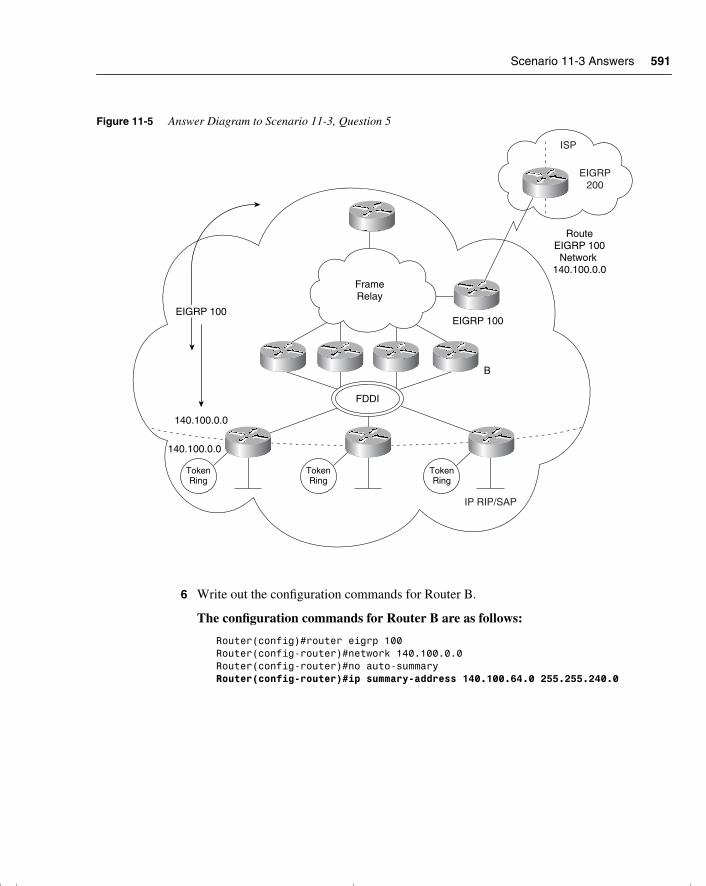
Scenario 11-3 Answers 591
Figure 11-5 Answer Diagram to Scenario 11-3, Question 5
6 Write out the configuration commands for Router B.
The configuration commands for Router B are as follows:
Router(config)#router eigrp 100Router(config-router)#network 140.100.0.0Router(config-router)#no auto-summaryRouter(config-router)#ip summary-address 140.100.64.0 255.255.240.0
TokenRing
TokenRing
TokenRing
FDDI
ISP
IP RIP/SAP
EIGRP200
FrameRelay
140.100.0.0
140.100.0.0
EIGRP 100EIGRP 100
B
RouteEIGRP 100Network
140.100.0.0
chpt_01.book Page 591 Thursday, December 21, 2000 6:22 PM
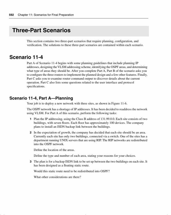
592 Chapter 11: Scenarios for Final Preparation
Three-Part Scenarios
This section contains two three-part scenarios that require planning, configuration, and verification. The solutions to these three-part scenarios are contained within each scenario.
Scenario 11-4Part A of Scenario 11-4 begins with some planning guidelines that include planning IP addresses, designing the VLSM addressing scheme, identifying the OSPF areas, and determining what type of areas they should be. After you complete Part A, Part B of the scenario asks you to configure the three routers to implement the planned design and a few other features. Finally, Part C asks you to examine router command output to discover details about the current operation. Part C also lists some questions related to the user interface and protocol specifications.
Scenario 11-4, Part A—PlanningYour job is to deploy a new network with three sites, as shown in Figure 11-6.
The OSPF network has a shortage of IP addresses. It has been decided to readdress the network using VLSM. For Part A of this scenario, perform the following tasks:
1 Plan the IP addressing, using the Class B address of 131.99.0.0. Each site consists of two buildings, with seven floors. Each floor has approximately 100 devices. The company plans to install an ISDN backup link between the buildings.
2 In the expectation of growth, the company has decided that each site should be an area. Currently each site has only two buildings, connected via a switch. One of the sites has a department running UNIX servers that are using RIP. The RIP networks are redistributed into the OSPF network.
Define the location of the areas.
Define the type and number of each area, stating your reasons for your choices.
3 The plan is for a backup ISDN link to be set up between the two buildings on each site. It has been designed as a floating static route.
Would this static route need to be redistributed into OSPF?
What other considerations are there?
chpt_01.book Page 592 Thursday, December 21, 2000 6:22 PM
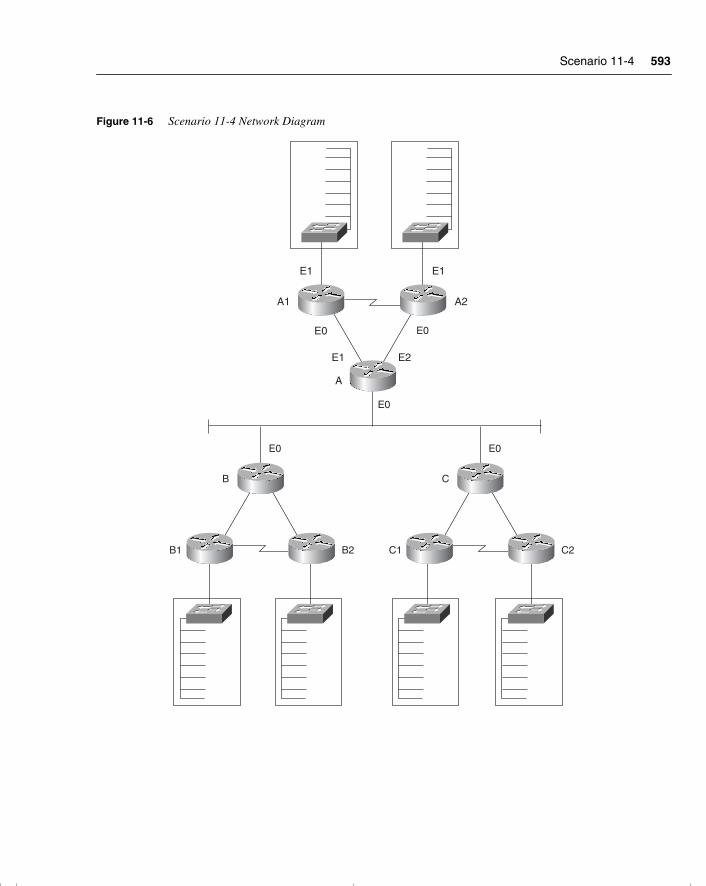
Scenario 11-4 593
Figure 11-6 Scenario 11-4 Network Diagram
B1
B
E0
E0
E0
B2 C1
C
E0
C2
A
A1 A2
E0
E1E1
E1 E2
chpt_01.book Page 593 Thursday, December 21, 2000 6:22 PM
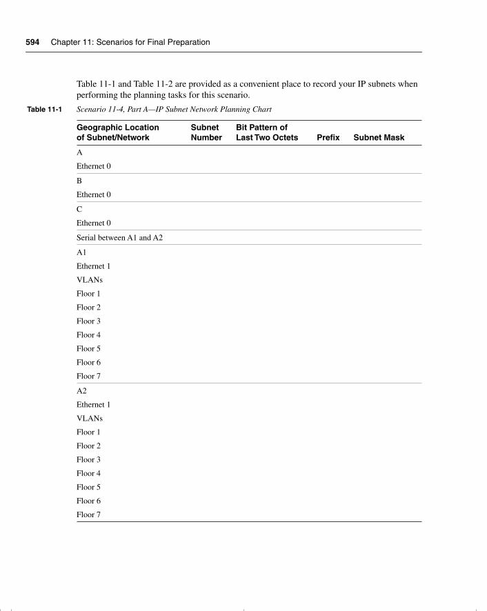
594 Chapter 11: Scenarios for Final Preparation
Table 11-1 and Table 11-2 are provided as a convenient place to record your IP subnets when performing the planning tasks for this scenario.
Table 11-1 Scenario 11-4, Part A—IP Subnet Network Planning Chart
Geographic Location of Subnet/Network
Subnet Number
Bit Pattern of Last Two Octets Prefix Subnet Mask
A
Ethernet 0
B
Ethernet 0
C
Ethernet 0
Serial between A1 and A2
A1
Ethernet 1
VLANs
Floor 1
Floor 2
Floor 3
Floor 4
Floor 5
Floor 6
Floor 7
A2
Ethernet 1
VLANs
Floor 1
Floor 2
Floor 3
Floor 4
Floor 5
Floor 6
Floor 7
chpt_01.book Page 594 Thursday, December 21, 2000 6:22 PM
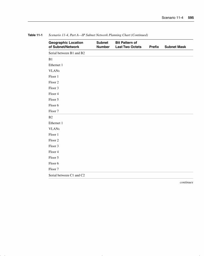
Scenario 11-4 595
Serial between B1 and B2
B1
Ethernet 1
VLANs
Floor 1
Floor 2
Floor 3
Floor 4
Floor 5
Floor 6
Floor 7
B2
Ethernet 1
VLANs
Floor 1
Floor 2
Floor 3
Floor 4
Floor 5
Floor 6
Floor 7
Serial between C1 and C2
continues
Table 11-1 Scenario 11-4, Part A—IP Subnet Network Planning Chart (Continued)
Geographic Location of Subnet/Network
Subnet Number
Bit Pattern of Last Two Octets Prefix Subnet Mask
chpt_01.book Page 595 Thursday, December 21, 2000 6:22 PM
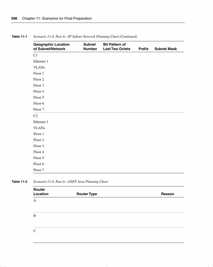
596 Chapter 11: Scenarios for Final Preparation
C1
Ethernet 1
VLANs
Floor 1
Floor 2
Floor 3
Floor 4
Floor 5
Floor 6
Floor 7
C2
Ethernet 1
VLANs
Floor 1
Floor 2
Floor 3
Floor 4
Floor 5
Floor 6
Floor 7
Table 11-2 Scenario 11-4, Part A—OSPF Area Planning Chart
Router Location Router Type Reason
A
B
C
Table 11-1 Scenario 11-4, Part A—IP Subnet Network Planning Chart (Continued)
Geographic Location of Subnet/Network
Subnet Number
Bit Pattern of Last Two Octets Prefix Subnet Mask
chpt_01.book Page 596 Thursday, December 21, 2000 6:22 PM
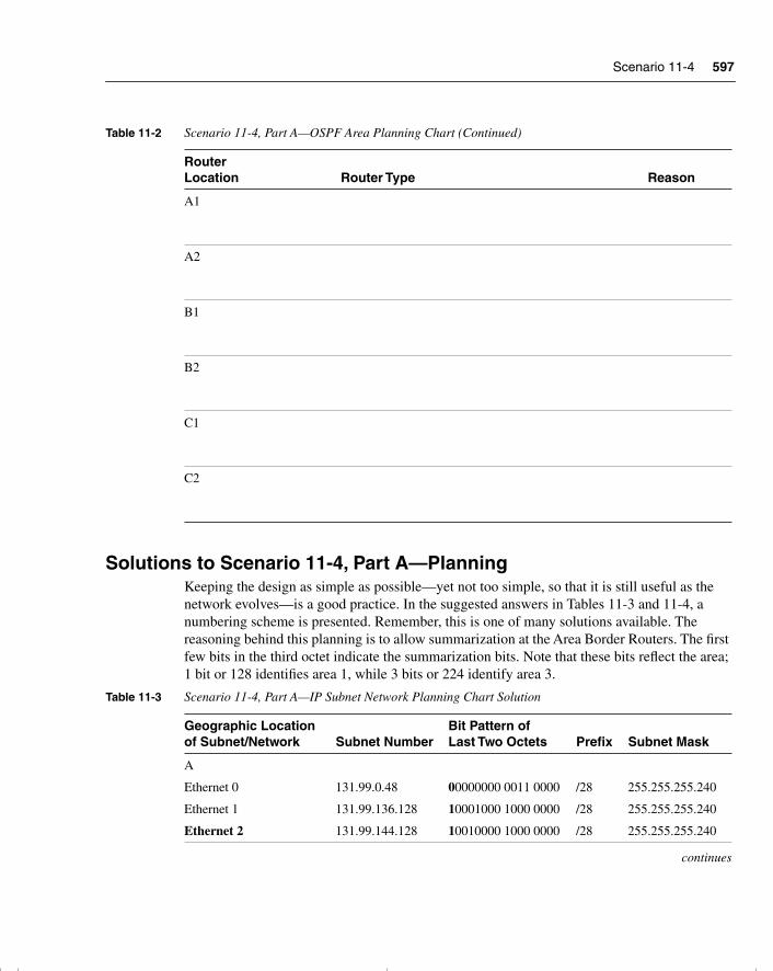
Scenario 11-4 597
Solutions to Scenario 11-4, Part A—Planning Keeping the design as simple as possible—yet not too simple, so that it is still useful as the network evolves—is a good practice. In the suggested answers in Tables 11-3 and 11-4, a numbering scheme is presented. Remember, this is one of many solutions available. The reasoning behind this planning is to allow summarization at the Area Border Routers. The first few bits in the third octet indicate the summarization bits. Note that these bits reflect the area; 1 bit or 128 identifies area 1, while 3 bits or 224 identify area 3.
A1
A2
B1
B2
C1
C2
Table 11-3 Scenario 11-4, Part A—IP Subnet Network Planning Chart Solution
Geographic Location of Subnet/Network Subnet Number
Bit Pattern of Last Two Octets Prefix Subnet Mask
A
Ethernet 0
Ethernet 1
Ethernet 2
131.99.0.48
131.99.136.128
131.99.144.128
00000000 0011 0000
10001000 1000 0000
10010000 1000 0000
/28
/28
/28
255.255.255.240
255.255.255.240
255.255.255.240
continues
Table 11-2 Scenario 11-4, Part A—OSPF Area Planning Chart (Continued)
Router Location Router Type Reason
chpt_01.book Page 597 Thursday, December 21, 2000 6:22 PM
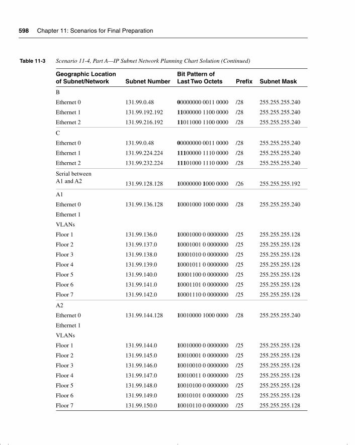
598 Chapter 11: Scenarios for Final Preparation
B
Ethernet 0
Ethernet 1
Ethernet 2
131.99.0.48
131.99.192.192
131.99.216.192
00000000 0011 0000
11000000 1100 0000
11011000 1100 0000
/28
/28
/28
255.255.255.240
255.255.255.240
255.255.255.240
C
Ethernet 0
Ethernet 1
Ethernet 2
131.99.0.48
131.99.224.224
131.99.232.224
00000000 0011 0000
11100000 1110 0000
11101000 1110 0000
/28
/28
/28
255.255.255.240
255.255.255.240
255.255.255.240
Serial between A1 and A2 131.99.128.128 10000000 1000 0000 /26 255.255.255.192
A1
Ethernet 0
Ethernet 1
VLANs
Floor 1
Floor 2
Floor 3
Floor 4
Floor 5
Floor 6
Floor 7
131.99.136.128
131.99.136.0
131.99.137.0
131.99.138.0
131.99.139.0
131.99.140.0
131.99.141.0
131.99.142.0
10001000 1000 0000
10001000 0 0000000
10001001 0 0000000
10001010 0 0000000
10001011 0 0000000
10001100 0 0000000
10001101 0 0000000
10001110 0 0000000
/28
/25
/25
/25
/25
/25
/25
/25
255.255.255.240
255.255.255.128
255.255.255.128
255.255.255.128
255.255.255.128
255.255.255.128
255.255.255.128
255.255.255.128
A2
Ethernet 0
Ethernet 1
VLANs
Floor 1
Floor 2
Floor 3
Floor 4
Floor 5
Floor 6
Floor 7
131.99.144.128
131.99.144.0
131.99.145.0
131.99.146.0
131.99.147.0
131.99.148.0
131.99.149.0
131.99.150.0
10010000 1000 0000
10010000 0 0000000
10010001 0 0000000
10010010 0 0000000
10010011 0 0000000
10010100 0 0000000
10010101 0 0000000
10010110 0 0000000
/28
/25
/25
/25
/25
/25
/25
/25
255.255.255.240
255.255.255.128
255.255.255.128
255.255.255.128
255.255.255.128
255.255.255.128
255.255.255.128
255.255.255.128
Table 11-3 Scenario 11-4, Part A—IP Subnet Network Planning Chart Solution (Continued)
Geographic Location of Subnet/Network Subnet Number
Bit Pattern of Last Two Octets Prefix Subnet Mask
chpt_01.book Page 598 Thursday, December 21, 2000 6:22 PM
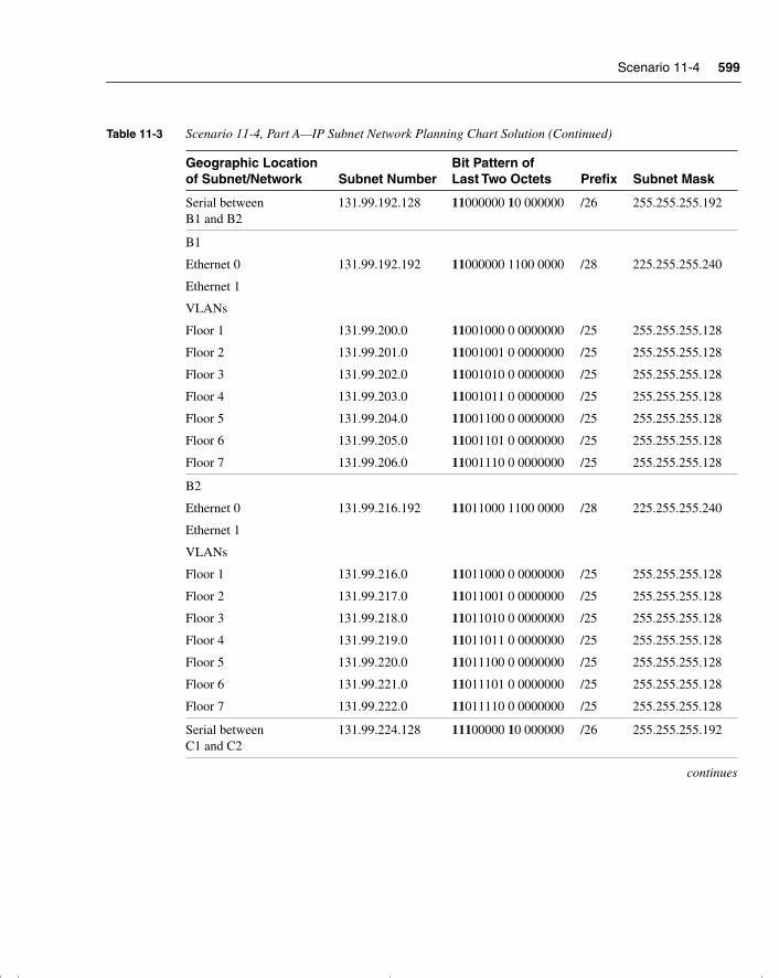
Scenario 11-4 599
Serial between B1 and B2
131.99.192.128 11000000 10 000000 /26 255.255.255.192
B1
Ethernet 0
Ethernet 1
VLANs
Floor 1
Floor 2
Floor 3
Floor 4
Floor 5
Floor 6
Floor 7
131.99.192.192
131.99.200.0
131.99.201.0
131.99.202.0
131.99.203.0
131.99.204.0
131.99.205.0
131.99.206.0
11000000 1100 0000
11001000 0 0000000
11001001 0 0000000
11001010 0 0000000
11001011 0 0000000
11001100 0 0000000
11001101 0 0000000
11001110 0 0000000
/28
/25
/25
/25
/25
/25
/25
/25
225.255.255.240
255.255.255.128
255.255.255.128
255.255.255.128
255.255.255.128
255.255.255.128
255.255.255.128
255.255.255.128
B2
Ethernet 0
Ethernet 1
VLANs
Floor 1
Floor 2
Floor 3
Floor 4
Floor 5
Floor 6
Floor 7
131.99.216.192
131.99.216.0
131.99.217.0
131.99.218.0
131.99.219.0
131.99.220.0
131.99.221.0
131.99.222.0
11011000 1100 0000
11011000 0 0000000
11011001 0 0000000
11011010 0 0000000
11011011 0 0000000
11011100 0 0000000
11011101 0 0000000
11011110 0 0000000
/28
/25
/25
/25
/25
/25
/25
/25
225.255.255.240
255.255.255.128
255.255.255.128
255.255.255.128
255.255.255.128
255.255.255.128
255.255.255.128
255.255.255.128
Serial between C1 and C2
131.99.224.128 11100000 10 000000 /26 255.255.255.192
continues
Table 11-3 Scenario 11-4, Part A—IP Subnet Network Planning Chart Solution (Continued)
Geographic Location of Subnet/Network Subnet Number
Bit Pattern of Last Two Octets Prefix Subnet Mask
chpt_01.book Page 599 Thursday, December 21, 2000 6:22 PM
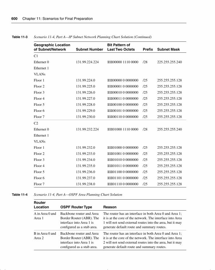
600 Chapter 11: Scenarios for Final Preparation
C1
Ethernet 0
Ethernet 1
VLANs
Floor 1
Floor 2
Floor 3
Floor 4
Floor 5
Floor 6
Floor 7
131.99.224.224
131.99.224.0
131.99.225.0
131.99.226.0
131.99.227.0
131.99.228.0
131.99.229.0
131.99.230.0
11100000 1110 0000
11100000 0 0000000
11100001 0 0000000
11100010 0 0000000
11100011 0 0000000
11100100 0 0000000
11100101 0 0000000
11100110 0 0000000
/28
/25
/25
/25
/25
/25
/25
/25
225.255.255.240
255.255.255.128
255.255.255.128
255.255.255.128
255.255.255.128
255.255.255.128
255.255.255.128
255.255.255.128
C2
Ethernet 0
Ethernet 1
VLANs
Floor 1
Floor 2
Floor 3
Floor 4
Floor 5
Floor 6
Floor 7
131.99.232.224
131.99.232.0
131.99.233.0
131.99.234.0
131.99.235.0
131.99.236.0
131.99.237.0
131.99.238.0
11101000 1110 0000
11101000 0 0000000
11101001 0 0000000
11101010 0 0000000
11101011 0 0000000
11101100 0 0000000
11101101 0 0000000
11101110 0 0000000
/28
/25
/25
/25
/25
/25
/25
/25
255.255.255.240
255.255.255.128
255.255.255.128
255.255.255.128
255.255.255.128
255.255.255.128
255.255.255.128
255.255.255.128
Table 11-4 Scenario 11-4, Part A—OSPF Area Planning Chart Solution
Router Location OSPF Router Type Reason
A in Area 0 and Area 1
Backbone router and Area Border Router (ABR). The interface into Area 1 is configured as a stub area.
The router has an interface in both Area 0 and Area 1; it is at the core of the network. The interface into Area 1 will not send external routes into the area, but it may generate default route and summary routes.
B in Area 0 and Area 2
Backbone router and Area Border Router (ABR). The interface into Area 1 is configured as a stub area.
The router has an interface in both Area 0 and Area 1; it is at the core of the network. The interface into Area 2 will not send external routes into the area, but it may generate default route and summary routes.
Table 11-3 Scenario 11-4, Part A—IP Subnet Network Planning Chart Solution (Continued)
Geographic Location of Subnet/Network Subnet Number
Bit Pattern of Last Two Octets Prefix Subnet Mask
chpt_01.book Page 600 Thursday, December 21, 2000 6:22 PM
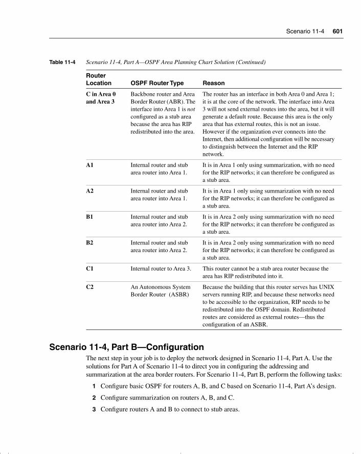
Scenario 11-4 601
Scenario 11-4, Part B—ConfigurationThe next step in your job is to deploy the network designed in Scenario 11-4, Part A. Use the solutions for Part A of Scenario 11-4 to direct you in configuring the addressing and summarization at the area border routers. For Scenario 11-4, Part B, perform the following tasks:
1 Configure basic OSPF for routers A, B, and C based on Scenario 11-4, Part A’s design.
2 Configure summarization on routers A, B, and C.
3 Configure routers A and B to connect to stub areas.
C in Area 0 and Area 3
Backbone router and Area Border Router (ABR). The interface into Area 1 is not configured as a stub area because the area has RIP redistributed into the area.
The router has an interface in both Area 0 and Area 1; it is at the core of the network. The interface into Area 3 will not send external routes into the area, but it will generate a default route. Because this area is the only area that has external routes, this is not an issue. However if the organization ever connects into the Internet, then additional configuration will be necessary to distinguish between the Internet and the RIP network.
A1 Internal router and stub area router into Area 1.
It is in Area 1 only using summarization, with no need for the RIP networks; it can therefore be configured as a stub area.
A2 Internal router and stub area router into Area 1.
It is in Area 1 only using summarization with no need for the RIP networks; it can therefore be configured as a stub area.
B1 Internal router and stub area router into Area 2.
It is in Area 2 only using summarization with no need for the RIP networks; it can therefore be configured as a stub area.
B2 Internal router and stub area router into Area 2.
It is in Area 2 only using summarization with no need for the RIP networks; it can therefore be configured as a stub area.
C1 Internal router to Area 3. This router cannot be a stub area router because the area has RIP redistributed into it.
C2 An Autonomous System Border Router (ASBR)
Because the building that this router serves has UNIX servers running RIP, and because these networks need to be accessible to the organization, RIP needs to be redistributed into the OSPF domain. Redistributed routes are considered as external routes—thus the configuration of an ASBR.
Table 11-4 Scenario 11-4, Part A—OSPF Area Planning Chart Solution (Continued)
Router Location OSPF Router Type Reason
chpt_01.book Page 601 Thursday, December 21, 2000 6:22 PM
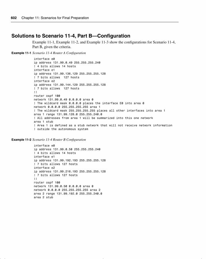
602 Chapter 11: Scenarios for Final Preparation
Solutions to Scenario 11-4, Part B—Configuration Example 11-1, Example 11-2, and Example 11-3 show the configurations for Scenario 11-4, Part B, given the criteria.
Example 11-1 Scenario 11-4 Router A Configuration
interface e0ip address 131.99.0.49 255.255.255.240! 4 bits allows 14 hostsinterface e1ip address 131.99.136.129 255.255.255.128! 7 bits allows 127 hostsinterface e2ip address 131.99.144.129 255.255.255.128! 7 bits allows 127 hosts!!router ospf 100 network 131.99.0.49 0.0.0.0 area 0! The wildcard mask 0.0.0.0 places the interface E0 into area 0network 0.0.0.0 255.255.255.255 area 1! The wildcard mask 255.255.255.255 places all other interfaces into area 1area 1 range 131.99.128.0 255.255.240.0! All addresses from area 1 will be summarized into this one networkarea 1 stub! Area 1 is defined as a stub network that will not receive network information! outside the autonomous system
Example 11-2 Scenario 11-4 Router B Configuration
interface e0ip address 131.99.0.50 255.255.255.240! 4 bits allows 14 hostsinterface e1ip address 131.99.192.193 255.255.255.128! 7 bits allows 127 hostsinterface e2ip address 131.99.216.193 255.255.255.128! 7 bits allows 127 hosts!!router ospf 100 network 131.99.0.50 0.0.0.0 area 0network 0.0.0.0 255.255.255.255 area 2area 2 range 131.99.192.0 255.255.240.0area 2 stub
chpt_01.book Page 602 Thursday, December 21, 2000 6:22 PM
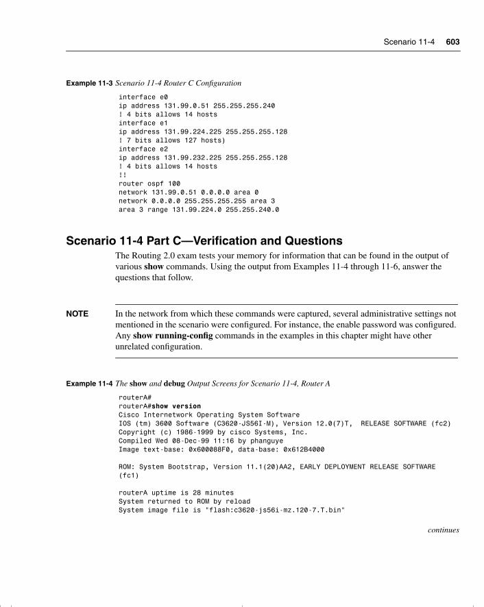
Scenario 11-4 603
Scenario 11-4 Part C—Verification and QuestionsThe Routing 2.0 exam tests your memory for information that can be found in the output of various show commands. Using the output from Examples 11-4 through 11-6, answer the questions that follow.
NOTE In the network from which these commands were captured, several administrative settings not mentioned in the scenario were configured. For instance, the enable password was configured. Any show running-config commands in the examples in this chapter might have other unrelated configuration.
Example 11-3 Scenario 11-4 Router C Configuration
interface e0ip address 131.99.0.51 255.255.255.240! 4 bits allows 14 hostsinterface e1ip address 131.99.224.225 255.255.255.128! 7 bits allows 127 hosts)interface e2ip address 131.99.232.225 255.255.255.128! 4 bits allows 14 hosts!!router ospf 100 network 131.99.0.51 0.0.0.0 area 0network 0.0.0.0 255.255.255.255 area 3area 3 range 131.99.224.0 255.255.240.0
Example 11-4 The show and debug Output Screens for Scenario 11-4, Router A
routerA#routerA#show versionCisco Internetwork Operating System SoftwareIOS (tm) 3600 Software (C3620-JS56I-M), Version 12.0(7)T, RELEASE SOFTWARE (fc2)Copyright (c) 1986-1999 by cisco Systems, Inc.Compiled Wed 08-Dec-99 11:16 by phanguyeImage text-base: 0x600088F0, data-base: 0x612B4000 ROM: System Bootstrap, Version 11.1(20)AA2, EARLY DEPLOYMENT RELEASE SOFTWARE (fc1) routerA uptime is 28 minutesSystem returned to ROM by reloadSystem image file is "flash:c3620-js56i-mz.120-7.T.bin"
continues
chpt_01.book Page 603 Thursday, December 21, 2000 6:22 PM
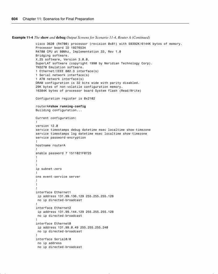
604 Chapter 11: Scenarios for Final Preparation
cisco 3620 (R4700) processor (revision 0x81) with 59392K/6144K bytes of memory.Processor board ID 19276534R4700 CPU at 80Mhz, Implementation 33, Rev 1.0Bridging software.X.25 software, Version 3.0.0.SuperLAT software (copyright 1990 by Meridian Technology Corp).TN3270 Emulation software.1 Ethernet/IEEE 802.3 interface(s)1 Serial network interface(s)1 ATM network interface(s)DRAM configuration is 32 bits wide with parity disabled.29K bytes of non-volatile configuration memory.16384K bytes of processor board System flash (Read/Write) Configuration register is 0x2102 routerA#show running-configBuilding configuration... Current configuration:!version 12.0service timestamps debug datetime msec localtime show-timezoneservice timestamps log datetime msec localtime show-timezoneservice password-encryption!hostname routerA!enable password 7 1511021F0725!!!ip subnet-zero!cns event-service server!!!interface Ethernet1 ip address 131.99.136.129 255.255.255.128 no ip directed-broadcast!interface Ethernet2 ip address 131.99.144.129 255.255.255.128 no ip directed-broadcast!interface Ethernet0 ip address 131.99.0.49 255.255.255.240 no ip directed-broadcast!interface Serial0/0 no ip address no ip directed-broadcast
Example 11-4 The show and debug Output Screens for Scenario 11-4, Router A (Continued)
chpt_01.book Page 604 Thursday, December 21, 2000 6:22 PM

Scenario 11-4 605
no ip mroute-cache shutdown no fair-queue!interface ATM1/0 no ip address no ip directed-broadcast shutdown no atm ilmi-keepalive!router ospf 100 area 1 stub area 1 range 131.99.128.0 255.255.240.0 network 131.99.0.49 0.0.0.0 area 0 network 0.0.0.0 255.255.255.255 area 1!ip classlessno ip http server!!!line con 0 transport input noneline aux 0line vty 0 4 password 7 045802150C2E login!end routerA#routerA#show interfaceEthernet0 is up, line protocol is up Hardware is AmdP2, address is 0001.96ea.af61 (bia 0001.96ea.af61) Internet address is 131.99.0.49/28 MTU 1500 bytes, BW 10000 Kbit, DLY 1000 usec, reliability 255/255, txload 1/255, rxload 1/255 Encapsulation ARPA, loopback not set Keepalive set (10 sec) ARP type: ARPA, ARP Timeout 04:00:00 Last input 00:00:05, output 00:00:05, output hang never Last clearing of "show interface" counters never Queueing strategy: fifoOutput queue 0/40, 0 drops; input queue 0/75, 0 drops 5 minute input rate 0 bits/sec, 0 packets/sec 5 minute output rate 0 bits/sec, 0 packets/sec 241 packets input, 22186 bytes, 0 no buffer Received 228 broadcasts, 0 runts, 0 giants, 0 throttles 0 input errors, 0 CRC, 0 frame, 0 overrun, 0 ignored 0 input packets with dribble condition detected 266 packets output, 35619 bytes, 0 underruns
continues
Example 11-4 The show and debug Output Screens for Scenario 11-4, Router A (Continued)
chpt_01.book Page 605 Thursday, December 21, 2000 6:22 PM
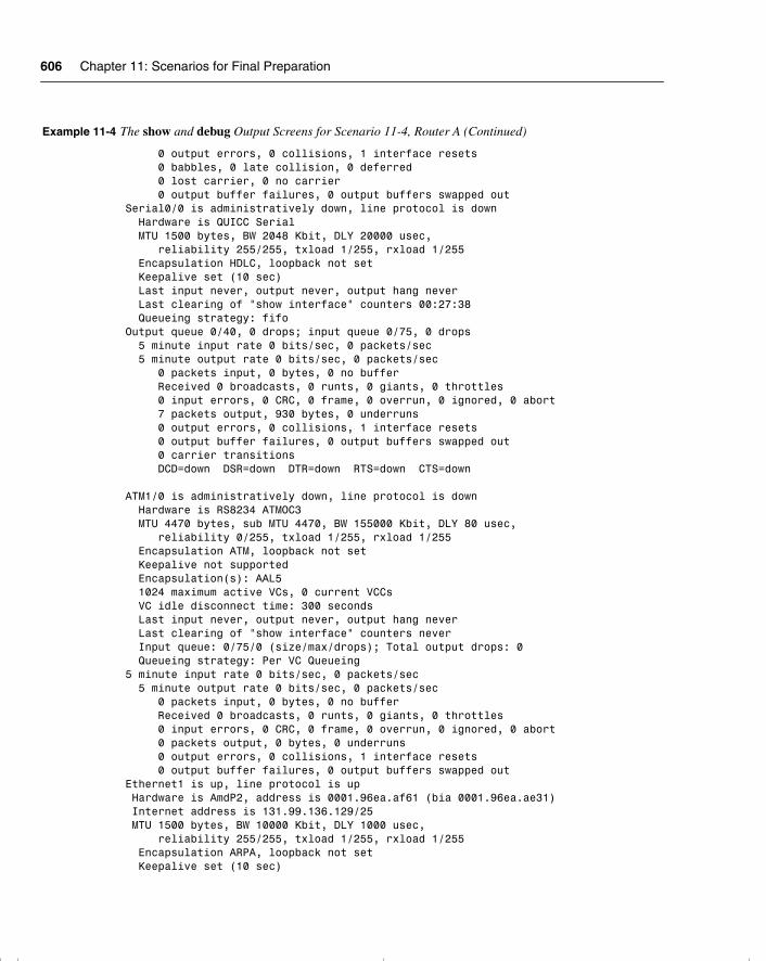
606 Chapter 11: Scenarios for Final Preparation
0 output errors, 0 collisions, 1 interface resets 0 babbles, 0 late collision, 0 deferred 0 lost carrier, 0 no carrier 0 output buffer failures, 0 output buffers swapped outSerial0/0 is administratively down, line protocol is down Hardware is QUICC Serial MTU 1500 bytes, BW 2048 Kbit, DLY 20000 usec, reliability 255/255, txload 1/255, rxload 1/255 Encapsulation HDLC, loopback not set Keepalive set (10 sec) Last input never, output never, output hang never Last clearing of "show interface" counters 00:27:38 Queueing strategy: fifoOutput queue 0/40, 0 drops; input queue 0/75, 0 drops 5 minute input rate 0 bits/sec, 0 packets/sec 5 minute output rate 0 bits/sec, 0 packets/sec 0 packets input, 0 bytes, 0 no buffer Received 0 broadcasts, 0 runts, 0 giants, 0 throttles 0 input errors, 0 CRC, 0 frame, 0 overrun, 0 ignored, 0 abort 7 packets output, 930 bytes, 0 underruns 0 output errors, 0 collisions, 1 interface resets 0 output buffer failures, 0 output buffers swapped out 0 carrier transitions DCD=down DSR=down DTR=down RTS=down CTS=down ATM1/0 is administratively down, line protocol is down Hardware is RS8234 ATMOC3 MTU 4470 bytes, sub MTU 4470, BW 155000 Kbit, DLY 80 usec, reliability 0/255, txload 1/255, rxload 1/255 Encapsulation ATM, loopback not set Keepalive not supported Encapsulation(s): AAL5 1024 maximum active VCs, 0 current VCCs VC idle disconnect time: 300 seconds Last input never, output never, output hang never Last clearing of "show interface" counters never Input queue: 0/75/0 (size/max/drops); Total output drops: 0 Queueing strategy: Per VC Queueing5 minute input rate 0 bits/sec, 0 packets/sec 5 minute output rate 0 bits/sec, 0 packets/sec 0 packets input, 0 bytes, 0 no buffer Received 0 broadcasts, 0 runts, 0 giants, 0 throttles 0 input errors, 0 CRC, 0 frame, 0 overrun, 0 ignored, 0 abort 0 packets output, 0 bytes, 0 underruns 0 output errors, 0 collisions, 1 interface resets 0 output buffer failures, 0 output buffers swapped outEthernet1 is up, line protocol is up Hardware is AmdP2, address is 0001.96ea.af61 (bia 0001.96ea.ae31) Internet address is 131.99.136.129/25 MTU 1500 bytes, BW 10000 Kbit, DLY 1000 usec, reliability 255/255, txload 1/255, rxload 1/255 Encapsulation ARPA, loopback not set Keepalive set (10 sec)
Example 11-4 The show and debug Output Screens for Scenario 11-4, Router A (Continued)
chpt_01.book Page 606 Thursday, December 21, 2000 6:22 PM
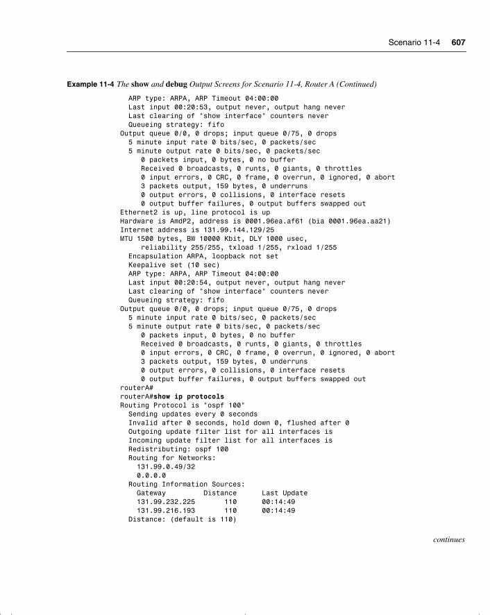
Scenario 11-4 607
ARP type: ARPA, ARP Timeout 04:00:00 Last input 00:20:53, output never, output hang never Last clearing of "show interface" counters never Queueing strategy: fifoOutput queue 0/0, 0 drops; input queue 0/75, 0 drops 5 minute input rate 0 bits/sec, 0 packets/sec 5 minute output rate 0 bits/sec, 0 packets/sec 0 packets input, 0 bytes, 0 no buffer Received 0 broadcasts, 0 runts, 0 giants, 0 throttles 0 input errors, 0 CRC, 0 frame, 0 overrun, 0 ignored, 0 abort 3 packets output, 159 bytes, 0 underruns 0 output errors, 0 collisions, 0 interface resets 0 output buffer failures, 0 output buffers swapped outEthernet2 is up, line protocol is upHardware is AmdP2, address is 0001.96ea.af61 (bia 0001.96ea.aa21)Internet address is 131.99.144.129/25MTU 1500 bytes, BW 10000 Kbit, DLY 1000 usec, reliability 255/255, txload 1/255, rxload 1/255 Encapsulation ARPA, loopback not set Keepalive set (10 sec) ARP type: ARPA, ARP Timeout 04:00:00 Last input 00:20:54, output never, output hang never Last clearing of "show interface" counters never Queueing strategy: fifoOutput queue 0/0, 0 drops; input queue 0/75, 0 drops 5 minute input rate 0 bits/sec, 0 packets/sec 5 minute output rate 0 bits/sec, 0 packets/sec 0 packets input, 0 bytes, 0 no buffer Received 0 broadcasts, 0 runts, 0 giants, 0 throttles 0 input errors, 0 CRC, 0 frame, 0 overrun, 0 ignored, 0 abort 3 packets output, 159 bytes, 0 underruns 0 output errors, 0 collisions, 0 interface resets 0 output buffer failures, 0 output buffers swapped outrouterA#routerA#show ip protocolsRouting Protocol is "ospf 100" Sending updates every 0 seconds Invalid after 0 seconds, hold down 0, flushed after 0 Outgoing update filter list for all interfaces is Incoming update filter list for all interfaces is Redistributing: ospf 100 Routing for Networks: 131.99.0.49/32 0.0.0.0 Routing Information Sources: Gateway Distance Last Update 131.99.232.225 110 00:14:49 131.99.216.193 110 00:14:49 Distance: (default is 110)
continues
Example 11-4 The show and debug Output Screens for Scenario 11-4, Router A (Continued)
chpt_01.book Page 607 Thursday, December 21, 2000 6:22 PM
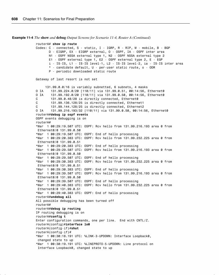
608 Chapter 11: Scenarios for Final Preparation
routerA# show ip routeCodes: C - connected, S - static, I - IGRP, R - RIP, M - mobile, B - BGP D - EIGRP, EX - EIGRP external, O - OSPF, IA - OSPF inter area N1 - OSPF NSSA external type 1, N2 - OSPF NSSA external type 2 E1 - OSPF external type 1, E2 - OSPF external type 2, E - EGP i - IS-IS, L1 - IS-IS level-1, L2 - IS-IS level-2, ia - IS-IS inter area * - candidate default, U - per-user static route, o - ODR P - periodic downloaded static route Gateway of last resort is not set 131.99.0.0/16 is variably subnetted, 6 subnets, 4 masksO IA 131.99.224.0/20 [110/11] via 131.99.0.51, 00:14:56, Ethernet0O IA 131.99.192.0/20 [110/11] via 131.99.0.50, 00:14:56, Ethernet0C 131.99.0.48/28 is directly connected, Ethernet0C 131.99.136.128/25 is directly connected, Ethernet1C 131.99.144.128/25 is directly connected, Ethernet2O IA 131.99.216.193/32 [110/11] via 131.99.0.50, 00:14:56, Ethernet0routerA#debug ip ospf eventsOSPF events debugging is onrouterA#*Mar 1 00:29:19.507 UTC: OSPF: Rcv hello from 131.99.216.193 area 0 from Ethernet0/0 131.99.0.50*Mar 1 00:29:19.507 UTC: OSPF: End of hello processing*Mar 1 00:29:20.383 UTC: OSPF: Rcv hello from 131.99.232.225 area 0 from Ethernet0/0 131.99.0.51*Mar 1 00:29:20.383 UTC: OSPF: End of hello processing*Mar 1 00:29:29.507 UTC: OSPF: Rcv hello from 131.99.216.193 area 0 from Ethernet0/0 131.99.0.50*Mar 1 00:29:29.507 UTC: OSPF: End of hello processing*Mar 1 00:29:30.383 UTC: OSPF: Rcv hello from 131.99.232.225 area 0 from Ethernet0/0 131.99.0.51*Mar 1 00:29:30.383 UTC: OSPF: End of hello processing*Mar 1 00:29:39.507 UTC: OSPF: Rcv hello from 131.99.216.193 area 0 from Ethernet0/0 131.99.0.50*Mar 1 00:29:39.507 UTC: OSPF: End of hello processing*Mar 1 00:29:40.383 UTC: OSPF: Rcv hello from 131.99.232.225 area 0 from Ethernet0/0 131.99.0.51*Mar 1 00:29:40.383 UTC: OSPF: End of hello processingrouterA#undebug allAll possible debugging has been turned offrouterA#routerA#debug ip routingIP routing debugging is onrouterA#config tEnter configuration commands, one per line. End with CNTL/Z.routerA(config)#interface lo0routerA(config-if)#shutrouterA(config-if)#*Mar 1 00:30:18.191 UTC: %LINK-3-UPDOWN: Interface Loopback0, changed state to up*Mar 1 00:30:19.191 UTC: %LINEPROTO-5-UPDOWN: Line protocol on Interface Loopback0, changed state to up
Example 11-4 The show and debug Output Screens for Scenario 11-4, Router A (Continued)
chpt_01.book Page 608 Thursday, December 21, 2000 6:22 PM
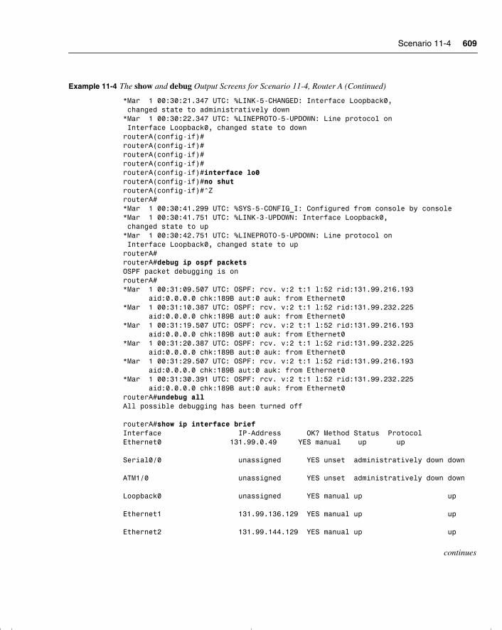
Scenario 11-4 609
*Mar 1 00:30:21.347 UTC: %LINK-5-CHANGED: Interface Loopback0, changed state to administratively down*Mar 1 00:30:22.347 UTC: %LINEPROTO-5-UPDOWN: Line protocol on Interface Loopback0, changed state to downrouterA(config-if)#routerA(config-if)#routerA(config-if)#routerA(config-if)#routerA(config-if)#interface lo0routerA(config-if)#no shutrouterA(config-if)#^ZrouterA#*Mar 1 00:30:41.299 UTC: %SYS-5-CONFIG_I: Configured from console by console*Mar 1 00:30:41.751 UTC: %LINK-3-UPDOWN: Interface Loopback0, changed state to up*Mar 1 00:30:42.751 UTC: %LINEPROTO-5-UPDOWN: Line protocol on Interface Loopback0, changed state to uprouterA#routerA#debug ip ospf packetsOSPF packet debugging is onrouterA#*Mar 1 00:31:09.507 UTC: OSPF: rcv. v:2 t:1 l:52 rid:131.99.216.193 aid:0.0.0.0 chk:189B aut:0 auk: from Ethernet0*Mar 1 00:31:10.387 UTC: OSPF: rcv. v:2 t:1 l:52 rid:131.99.232.225 aid:0.0.0.0 chk:189B aut:0 auk: from Ethernet0*Mar 1 00:31:19.507 UTC: OSPF: rcv. v:2 t:1 l:52 rid:131.99.216.193 aid:0.0.0.0 chk:189B aut:0 auk: from Ethernet0*Mar 1 00:31:20.387 UTC: OSPF: rcv. v:2 t:1 l:52 rid:131.99.232.225 aid:0.0.0.0 chk:189B aut:0 auk: from Ethernet0*Mar 1 00:31:29.507 UTC: OSPF: rcv. v:2 t:1 l:52 rid:131.99.216.193 aid:0.0.0.0 chk:189B aut:0 auk: from Ethernet0*Mar 1 00:31:30.391 UTC: OSPF: rcv. v:2 t:1 l:52 rid:131.99.232.225 aid:0.0.0.0 chk:189B aut:0 auk: from Ethernet0routerA#undebug allAll possible debugging has been turned off
routerA#show ip interface briefInterface IP-Address OK? Method Status ProtocolEthernet0 131.99.0.49 YES manual up up Serial0/0 unassigned YES unset administratively down down ATM1/0 unassigned YES unset administratively down down Loopback0 unassigned YES manual up up Ethernet1 131.99.136.129 YES manual up up Ethernet2 131.99.144.129 YES manual up up
continues
Example 11-4 The show and debug Output Screens for Scenario 11-4, Router A (Continued)
chpt_01.book Page 609 Thursday, December 21, 2000 6:22 PM
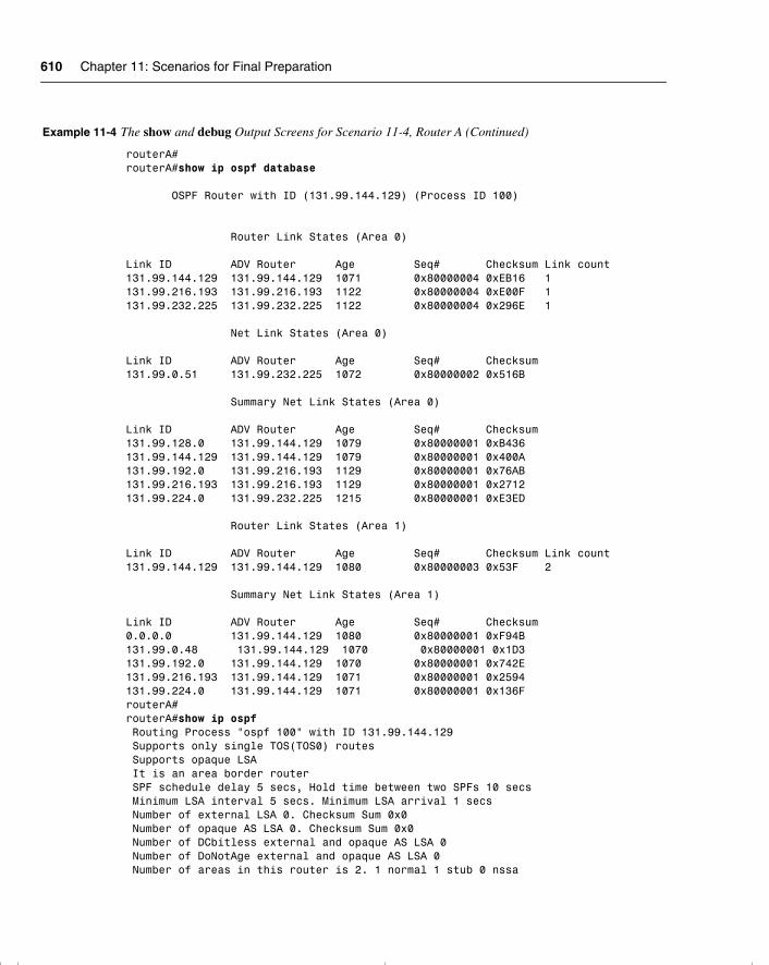
610 Chapter 11: Scenarios for Final Preparation
routerA#routerA#show ip ospf database OSPF Router with ID (131.99.144.129) (Process ID 100) Router Link States (Area 0) Link ID ADV Router Age Seq# Checksum Link count131.99.144.129 131.99.144.129 1071 0x80000004 0xEB16 1131.99.216.193 131.99.216.193 1122 0x80000004 0xE00F 1131.99.232.225 131.99.232.225 1122 0x80000004 0x296E 1 Net Link States (Area 0) Link ID ADV Router Age Seq# Checksum131.99.0.51 131.99.232.225 1072 0x80000002 0x516B Summary Net Link States (Area 0) Link ID ADV Router Age Seq# Checksum131.99.128.0 131.99.144.129 1079 0x80000001 0xB436131.99.144.129 131.99.144.129 1079 0x80000001 0x400A131.99.192.0 131.99.216.193 1129 0x80000001 0x76AB131.99.216.193 131.99.216.193 1129 0x80000001 0x2712131.99.224.0 131.99.232.225 1215 0x80000001 0xE3ED Router Link States (Area 1) Link ID ADV Router Age Seq# Checksum Link count131.99.144.129 131.99.144.129 1080 0x80000003 0x53F 2 Summary Net Link States (Area 1) Link ID ADV Router Age Seq# Checksum0.0.0.0 131.99.144.129 1080 0x80000001 0xF94B131.99.0.48 131.99.144.129 1070 0x80000001 0x1D3131.99.192.0 131.99.144.129 1070 0x80000001 0x742E131.99.216.193 131.99.144.129 1071 0x80000001 0x2594131.99.224.0 131.99.144.129 1071 0x80000001 0x136FrouterA#routerA#show ip ospf Routing Process "ospf 100" with ID 131.99.144.129 Supports only single TOS(TOS0) routes Supports opaque LSA It is an area border router SPF schedule delay 5 secs, Hold time between two SPFs 10 secs Minimum LSA interval 5 secs. Minimum LSA arrival 1 secs Number of external LSA 0. Checksum Sum 0x0 Number of opaque AS LSA 0. Checksum Sum 0x0 Number of DCbitless external and opaque AS LSA 0 Number of DoNotAge external and opaque AS LSA 0 Number of areas in this router is 2. 1 normal 1 stub 0 nssa
Example 11-4 The show and debug Output Screens for Scenario 11-4, Router A (Continued)
chpt_01.book Page 610 Thursday, December 21, 2000 6:22 PM
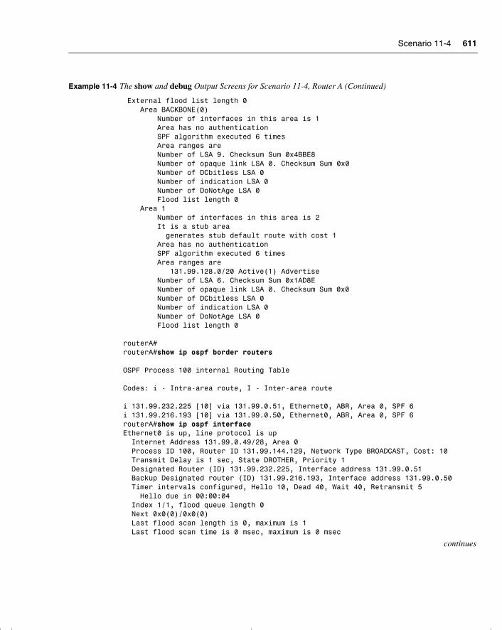
Scenario 11-4 611
External flood list length 0 Area BACKBONE(0) Number of interfaces in this area is 1 Area has no authentication SPF algorithm executed 6 times Area ranges are Number of LSA 9. Checksum Sum 0x4BBE8 Number of opaque link LSA 0. Checksum Sum 0x0 Number of DCbitless LSA 0 Number of indication LSA 0 Number of DoNotAge LSA 0 Flood list length 0 Area 1 Number of interfaces in this area is 2 It is a stub area generates stub default route with cost 1 Area has no authentication SPF algorithm executed 6 times Area ranges are 131.99.128.0/20 Active(1) Advertise Number of LSA 6. Checksum Sum 0x1AD8E Number of opaque link LSA 0. Checksum Sum 0x0 Number of DCbitless LSA 0 Number of indication LSA 0 Number of DoNotAge LSA 0 Flood list length 0 routerA#routerA#show ip ospf border routers OSPF Process 100 internal Routing Table Codes: i - Intra-area route, I - Inter-area route i 131.99.232.225 [10] via 131.99.0.51, Ethernet0, ABR, Area 0, SPF 6i 131.99.216.193 [10] via 131.99.0.50, Ethernet0, ABR, Area 0, SPF 6routerA#show ip ospf interfaceEthernet0 is up, line protocol is up Internet Address 131.99.0.49/28, Area 0 Process ID 100, Router ID 131.99.144.129, Network Type BROADCAST, Cost: 10 Transmit Delay is 1 sec, State DROTHER, Priority 1 Designated Router (ID) 131.99.232.225, Interface address 131.99.0.51 Backup Designated router (ID) 131.99.216.193, Interface address 131.99.0.50 Timer intervals configured, Hello 10, Dead 40, Wait 40, Retransmit 5 Hello due in 00:00:04 Index 1/1, flood queue length 0 Next 0x0(0)/0x0(0) Last flood scan length is 0, maximum is 1 Last flood scan time is 0 msec, maximum is 0 msec
continues
Example 11-4 The show and debug Output Screens for Scenario 11-4, Router A (Continued)
chpt_01.book Page 611 Thursday, December 21, 2000 6:22 PM
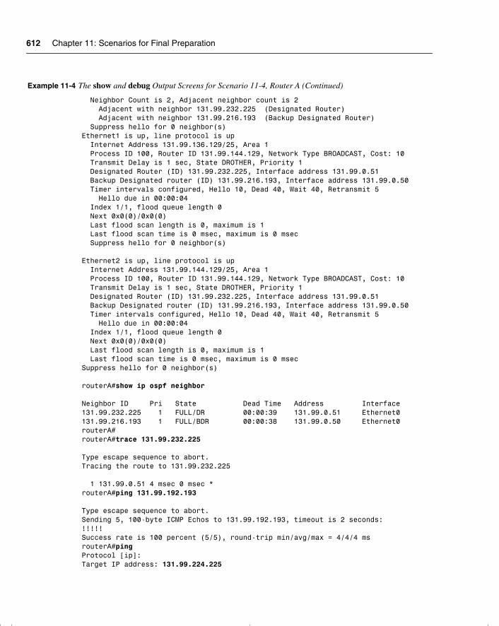
612 Chapter 11: Scenarios for Final Preparation
Neighbor Count is 2, Adjacent neighbor count is 2 Adjacent with neighbor 131.99.232.225 (Designated Router) Adjacent with neighbor 131.99.216.193 (Backup Designated Router) Suppress hello for 0 neighbor(s)Ethernet1 is up, line protocol is up Internet Address 131.99.136.129/25, Area 1 Process ID 100, Router ID 131.99.144.129, Network Type BROADCAST, Cost: 10 Transmit Delay is 1 sec, State DROTHER, Priority 1 Designated Router (ID) 131.99.232.225, Interface address 131.99.0.51 Backup Designated router (ID) 131.99.216.193, Interface address 131.99.0.50 Timer intervals configured, Hello 10, Dead 40, Wait 40, Retransmit 5 Hello due in 00:00:04 Index 1/1, flood queue length 0 Next 0x0(0)/0x0(0) Last flood scan length is 0, maximum is 1 Last flood scan time is 0 msec, maximum is 0 msec Suppress hello for 0 neighbor(s)
Ethernet2 is up, line protocol is up Internet Address 131.99.144.129/25, Area 1 Process ID 100, Router ID 131.99.144.129, Network Type BROADCAST, Cost: 10 Transmit Delay is 1 sec, State DROTHER, Priority 1 Designated Router (ID) 131.99.232.225, Interface address 131.99.0.51 Backup Designated router (ID) 131.99.216.193, Interface address 131.99.0.50 Timer intervals configured, Hello 10, Dead 40, Wait 40, Retransmit 5 Hello due in 00:00:04 Index 1/1, flood queue length 0 Next 0x0(0)/0x0(0) Last flood scan length is 0, maximum is 1 Last flood scan time is 0 msec, maximum is 0 msecSuppress hello for 0 neighbor(s)
routerA#show ip ospf neighbor Neighbor ID Pri State Dead Time Address Interface131.99.232.225 1 FULL/DR 00:00:39 131.99.0.51 Ethernet0131.99.216.193 1 FULL/BDR 00:00:38 131.99.0.50 Ethernet0routerA#routerA#trace 131.99.232.225 Type escape sequence to abort.Tracing the route to 131.99.232.225 1 131.99.0.51 4 msec 0 msec *routerA#ping 131.99.192.193 Type escape sequence to abort.Sending 5, 100-byte ICMP Echos to 131.99.192.193, timeout is 2 seconds:!!!!!Success rate is 100 percent (5/5), round-trip min/avg/max = 4/4/4 msrouterA#pingProtocol [ip]:Target IP address: 131.99.224.225
Example 11-4 The show and debug Output Screens for Scenario 11-4, Router A (Continued)
chpt_01.book Page 612 Thursday, December 21, 2000 6:22 PM
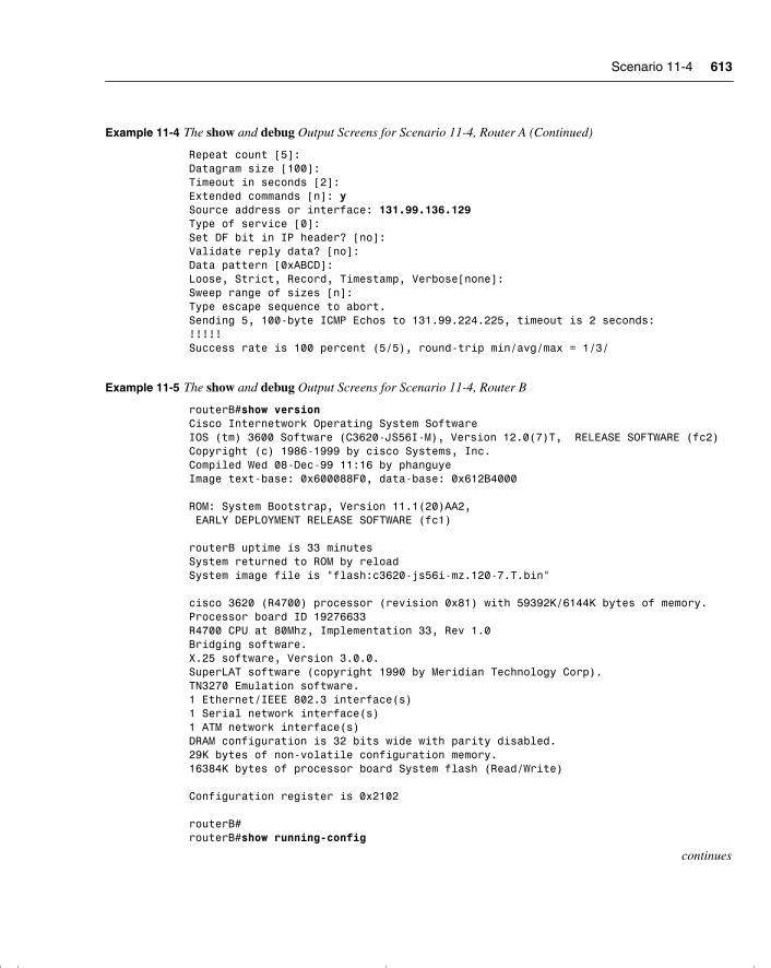
Scenario 11-4 613
Repeat count [5]:Datagram size [100]:Timeout in seconds [2]:Extended commands [n]: ySource address or interface: 131.99.136.129Type of service [0]:Set DF bit in IP header? [no]:Validate reply data? [no]:Data pattern [0xABCD]:Loose, Strict, Record, Timestamp, Verbose[none]:Sweep range of sizes [n]:Type escape sequence to abort.Sending 5, 100-byte ICMP Echos to 131.99.224.225, timeout is 2 seconds:!!!!!Success rate is 100 percent (5/5), round-trip min/avg/max = 1/3/
Example 11-5 The show and debug Output Screens for Scenario 11-4, Router B
routerB#show versionCisco Internetwork Operating System SoftwareIOS (tm) 3600 Software (C3620-JS56I-M), Version 12.0(7)T, RELEASE SOFTWARE (fc2)Copyright (c) 1986-1999 by cisco Systems, Inc.Compiled Wed 08-Dec-99 11:16 by phanguyeImage text-base: 0x600088F0, data-base: 0x612B4000 ROM: System Bootstrap, Version 11.1(20)AA2, EARLY DEPLOYMENT RELEASE SOFTWARE (fc1) routerB uptime is 33 minutesSystem returned to ROM by reloadSystem image file is "flash:c3620-js56i-mz.120-7.T.bin" cisco 3620 (R4700) processor (revision 0x81) with 59392K/6144K bytes of memory.Processor board ID 19276633R4700 CPU at 80Mhz, Implementation 33, Rev 1.0Bridging software.X.25 software, Version 3.0.0.SuperLAT software (copyright 1990 by Meridian Technology Corp).TN3270 Emulation software.1 Ethernet/IEEE 802.3 interface(s)1 Serial network interface(s)1 ATM network interface(s)DRAM configuration is 32 bits wide with parity disabled.29K bytes of non-volatile configuration memory.16384K bytes of processor board System flash (Read/Write) Configuration register is 0x2102 routerB#routerB#show running-config
continues
Example 11-4 The show and debug Output Screens for Scenario 11-4, Router A (Continued)
chpt_01.book Page 613 Thursday, December 21, 2000 6:22 PM
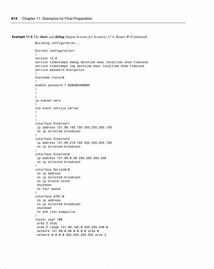
614 Chapter 11: Scenarios for Final Preparation
Building configuration... Current configuration:!version 12.0service timestamps debug datetime msec localtime show-timezoneservice timestamps log datetime msec localtime show-timezoneservice password-encryption!hostname routerB!enable password 7 02050D480809!!!ip subnet-zero!cns event-service server!!!interface Ethernet1 ip address 131.99.192.193 255.255.255.128 no ip directed-broadcast!interface Ethernet2 ip address 131.99.216.193 255.255.255.128 no ip directed-broadcast!interface Ethernet0 ip address 131.99.0.50 255.255.255.240 no ip directed-broadcast!interface Serial0/0 no ip address no ip directed-broadcast no ip mroute-cache shutdown no fair-queue!interface ATM1/0 no ip address no ip directed-broadcast shutdown no atm ilmi-keepalive!router ospf 100 area 2 stub area 2 range 131.99.192.0 255.255.240.0 network 131.99.0.50 0.0.0.0 area 0 network 0.0.0.0 255.255.255.255 area 2
Example 11-5 The show and debug Output Screens for Scenario 11-4, Router B (Continued)
chpt_01.book Page 614 Thursday, December 21, 2000 6:22 PM

Scenario 11-4 615
!ip classlessno ip http server!!!line con 0 transport input noneline aux 0line vty 0 4 password 7 110A1016141D login!end routerB#routerB#show interfaceEthernet0 is up, line protocol is up Hardware is AmdP2, address is 0001.96ea.ca41 (bia 0001.96ea.ca41) Internet address is 131.99.0.50/28 MTU 1500 bytes, BW 10000 Kbit, DLY 1000 usec, reliability 255/255, txload 1/255, rxload 1/255 Encapsulation ARPA, loopback not set Keepalive set (10 sec) ARP type: ARPA, ARP Timeout 04:00:00 Last input 00:00:01, output 00:00:02, output hang never Last clearing of "show interface" counters never Queueing strategy: fifoOutput queue 0/40, 0 drops; input queue 0/75, 0 drops 5 minute input rate 0 bits/sec, 0 packets/sec 5 minute output rate 0 bits/sec, 0 packets/sec 353 packets input, 33544 bytes, 0 no buffer Received 340 broadcasts, 0 runts, 0 giants, 0 throttles 0 input errors, 0 CRC, 0 frame, 0 overrun, 0 ignored 0 input packets with dribble condition detected 375 packets output, 48292 bytes, 0 underruns 0 output errors, 0 collisions, 1 interface resets 0 babbles, 0 late collision, 0 deferred 0 lost carrier, 0 no carrier 0 output buffer failures, 0 output buffers swapped outSerial0/0 is administratively down, line protocol is down Hardware is QUICC Serial MTU 1500 bytes, BW 2048 Kbit, DLY 20000 usec, reliability 255/255, txload 1/255, rxload 1/255 Encapsulation HDLC, loopback not set Keepalive set (10 sec) Last input never, output never, output hang never Last clearing of "show interface" counters 00:32:59 Queueing strategy: fifoOutput queue 0/40, 0 drops; input queue 0/75, 0 drops 5 minute input rate 0 bits/sec, 0 packets/sec
continues
Example 11-5 The show and debug Output Screens for Scenario 11-4, Router B (Continued)
chpt_01.book Page 615 Thursday, December 21, 2000 6:22 PM
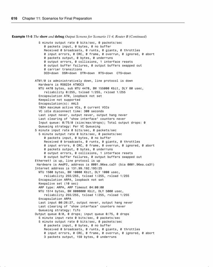
616 Chapter 11: Scenarios for Final Preparation
5 minute output rate 0 bits/sec, 0 packets/sec 0 packets input, 0 bytes, 0 no buffer Received 0 broadcasts, 0 runts, 0 giants, 0 throttles 0 input errors, 0 CRC, 0 frame, 0 overrun, 0 ignored, 0 abort 0 packets output, 0 bytes, 0 underruns 0 output errors, 0 collisions, 1 interface resets 0 output buffer failures, 0 output buffers swapped out 0 carrier transitions DCD=down DSR=down DTR=down RTS=down CTS=down ATM1/0 is administratively down, line protocol is down Hardware is RS8234 ATMOC3 MTU 4470 bytes, sub MTU 4470, BW 155000 Kbit, DLY 80 usec, reliability 0/255, txload 1/255, rxload 1/255 Encapsulation ATM, loopback not set Keepalive not supported Encapsulation(s): AAL5 1024 maximum active VCs, 0 current VCCs VC idle disconnect time: 300 seconds Last input never, output never, output hang never Last clearing of "show interface" counters never Input queue: 0/75/0 (size/max/drops); Total output drops: 0 Queueing strategy: Per VC Queueing5 minute input rate 0 bits/sec, 0 packets/sec 5 minute output rate 0 bits/sec, 0 packets/sec 0 packets input, 0 bytes, 0 no buffer Received 0 broadcasts, 0 runts, 0 giants, 0 throttles 0 input errors, 0 CRC, 0 frame, 0 overrun, 0 ignored, 0 abort 0 packets output, 0 bytes, 0 underruns 0 output errors, 0 collisions, 1 interface resets 0 output buffer failures, 0 output buffers swapped outEthernet1 is up, line protocol is up Hardware is AmdP2, address is 0001.96ea.ca31 (bia 0001.96ea.ca31)Internet address is 131.99.192.193/25 MTU 1500 bytes, BW 10000 Kbit, DLY 1000 usec, reliability 255/255, txload 1/255, rxload 1/255 Encapsulation ARPA, loopback not set Keepalive set (10 sec) ARP type: ARPA, ARP Timeout 04:00:00 MTU 1514 bytes, BW 8000000 Kbit, DLY 5000 usec, reliability 255/255, txload 1/255, rxload 1/255 Encapsulation ARPA Last input 00:26:27, output never, output hang never Last clearing of "show interface" counters never Queueing strategy: fifoOutput queue 0/0, 0 drops; input queue 0/75, 0 drops 5 minute input rate 0 bits/sec, 0 packets/sec 5 minute output rate 0 bits/sec, 0 packets/sec 0 packets input, 0 bytes, 0 no buffer Received 0 broadcasts, 0 runts, 0 giants, 0 throttles 0 input errors, 0 CRC, 0 frame, 0 overrun, 0 ignored, 0 abort 3 packets output, 159 bytes, 0 underruns
Example 11-5 The show and debug Output Screens for Scenario 11-4, Router B (Continued)
chpt_01.book Page 616 Thursday, December 21, 2000 6:22 PM
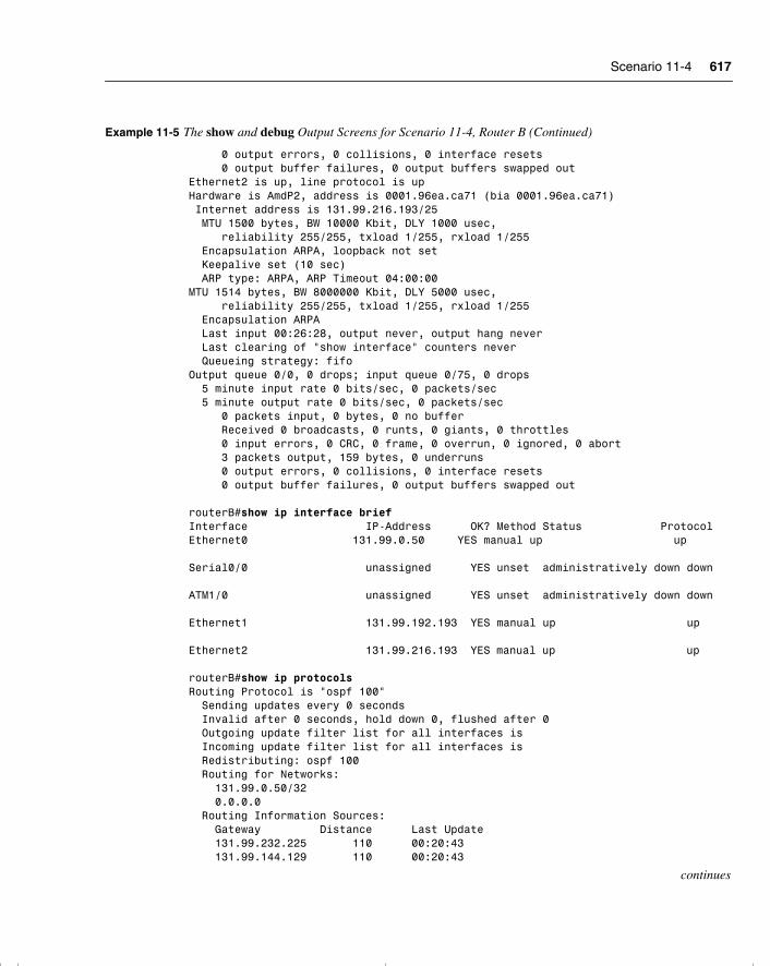
Scenario 11-4 617
0 output errors, 0 collisions, 0 interface resets 0 output buffer failures, 0 output buffers swapped outEthernet2 is up, line protocol is upHardware is AmdP2, address is 0001.96ea.ca71 (bia 0001.96ea.ca71) Internet address is 131.99.216.193/25 MTU 1500 bytes, BW 10000 Kbit, DLY 1000 usec, reliability 255/255, txload 1/255, rxload 1/255 Encapsulation ARPA, loopback not set Keepalive set (10 sec) ARP type: ARPA, ARP Timeout 04:00:00MTU 1514 bytes, BW 8000000 Kbit, DLY 5000 usec, reliability 255/255, txload 1/255, rxload 1/255 Encapsulation ARPA Last input 00:26:28, output never, output hang never Last clearing of "show interface" counters never Queueing strategy: fifoOutput queue 0/0, 0 drops; input queue 0/75, 0 drops 5 minute input rate 0 bits/sec, 0 packets/sec 5 minute output rate 0 bits/sec, 0 packets/sec 0 packets input, 0 bytes, 0 no buffer Received 0 broadcasts, 0 runts, 0 giants, 0 throttles 0 input errors, 0 CRC, 0 frame, 0 overrun, 0 ignored, 0 abort 3 packets output, 159 bytes, 0 underruns 0 output errors, 0 collisions, 0 interface resets 0 output buffer failures, 0 output buffers swapped out
routerB#show ip interface briefInterface IP-Address OK? Method Status ProtocolEthernet0 131.99.0.50 YES manual up up Serial0/0 unassigned YES unset administratively down down ATM1/0 unassigned YES unset administratively down down Ethernet1 131.99.192.193 YES manual up up Ethernet2 131.99.216.193 YES manual up up routerB#show ip protocolsRouting Protocol is "ospf 100" Sending updates every 0 seconds Invalid after 0 seconds, hold down 0, flushed after 0 Outgoing update filter list for all interfaces is Incoming update filter list for all interfaces is Redistributing: ospf 100 Routing for Networks: 131.99.0.50/32 0.0.0.0 Routing Information Sources: Gateway Distance Last Update 131.99.232.225 110 00:20:43 131.99.144.129 110 00:20:43
continues
Example 11-5 The show and debug Output Screens for Scenario 11-4, Router B (Continued)
chpt_01.book Page 617 Thursday, December 21, 2000 6:22 PM
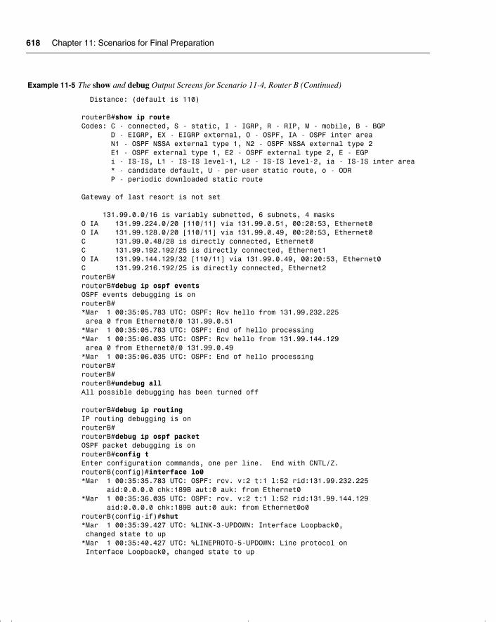
618 Chapter 11: Scenarios for Final Preparation
Distance: (default is 110) routerB#show ip routeCodes: C - connected, S - static, I - IGRP, R - RIP, M - mobile, B - BGP D - EIGRP, EX - EIGRP external, O - OSPF, IA - OSPF inter area N1 - OSPF NSSA external type 1, N2 - OSPF NSSA external type 2 E1 - OSPF external type 1, E2 - OSPF external type 2, E - EGP i - IS-IS, L1 - IS-IS level-1, L2 - IS-IS level-2, ia - IS-IS inter area * - candidate default, U - per-user static route, o - ODR P - periodic downloaded static route Gateway of last resort is not set 131.99.0.0/16 is variably subnetted, 6 subnets, 4 masksO IA 131.99.224.0/20 [110/11] via 131.99.0.51, 00:20:53, Ethernet0O IA 131.99.128.0/20 [110/11] via 131.99.0.49, 00:20:53, Ethernet0C 131.99.0.48/28 is directly connected, Ethernet0C 131.99.192.192/25 is directly connected, Ethernet1O IA 131.99.144.129/32 [110/11] via 131.99.0.49, 00:20:53, Ethernet0C 131.99.216.192/25 is directly connected, Ethernet2routerB#routerB#debug ip ospf eventsOSPF events debugging is onrouterB#*Mar 1 00:35:05.783 UTC: OSPF: Rcv hello from 131.99.232.225 area 0 from Ethernet0/0 131.99.0.51*Mar 1 00:35:05.783 UTC: OSPF: End of hello processing*Mar 1 00:35:06.035 UTC: OSPF: Rcv hello from 131.99.144.129 area 0 from Ethernet0/0 131.99.0.49*Mar 1 00:35:06.035 UTC: OSPF: End of hello processingrouterB#routerB#routerB#undebug allAll possible debugging has been turned off routerB#debug ip routingIP routing debugging is onrouterB#routerB#debug ip ospf packetOSPF packet debugging is onrouterB#config tEnter configuration commands, one per line. End with CNTL/Z.routerB(config)#interface lo0*Mar 1 00:35:35.783 UTC: OSPF: rcv. v:2 t:1 l:52 rid:131.99.232.225 aid:0.0.0.0 chk:189B aut:0 auk: from Ethernet0*Mar 1 00:35:36.035 UTC: OSPF: rcv. v:2 t:1 l:52 rid:131.99.144.129 aid:0.0.0.0 chk:189B aut:0 auk: from Ethernet0o0routerB(config-if)#shut*Mar 1 00:35:39.427 UTC: %LINK-3-UPDOWN: Interface Loopback0, changed state to up*Mar 1 00:35:40.427 UTC: %LINEPROTO-5-UPDOWN: Line protocol on Interface Loopback0, changed state to up
Example 11-5 The show and debug Output Screens for Scenario 11-4, Router B (Continued)
chpt_01.book Page 618 Thursday, December 21, 2000 6:22 PM
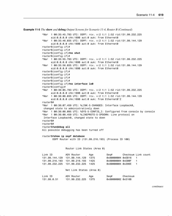
Scenario 11-4 619
*Mar 1 00:35:45.783 UTC: OSPF: rcv. v:2 t:1 l:52 rid:131.99.232.225 aid:0.0.0.0 chk:189B aut:0 auk: from Ethernet0*Mar 1 00:35:46.035 UTC: OSPF: rcv. v:2 t:1 l:52 rid:131.99.144.129 aid:0.0.0.0 chk:189B aut:0 auk: from Ethernet0routerB(config-if)#routerB(config-if)#routerB(config-if)#no shutrouterB(config-if)#*Mar 1 00:35:55.783 UTC: OSPF: rcv. v:2 t:1 l:52 rid:131.99.232.225 aid:0.0.0.0 chk:189B aut:0 auk: from Ethernet0*Mar 1 00:35:56.035 UTC: OSPF: rcv. v:2 t:1 l:52 rid:131.99.144.129 aid:0.0.0.0 chk:189B aut:0 auk: from Ethernet0routerB(config-if)#routerB(config-if)#routerB(config-if)#routerB(config-if)#routerB(config-if)#no interface lo0routerB(config)#*Mar 1 00:36:05.783 UTC: OSPF: rcv. v:2 t:1 l:52 rid:131.99.232.225 aid:0.0.0.0 chk:189B aut:0 auk: from Ethernet0*Mar 1 00:36:06.035 UTC: OSPF: rcv. v:2 t:1 l:52 rid:131.99.144.129 aid:0.0.0.0 chk:189B aut:0 auk: from Ethernet0^ZrouterB#*Mar 1 00:36:07.459 UTC: %LINK-5-CHANGED: Interface Loopback0, changed state to administratively down*Mar 1 00:36:08.095 UTC: %SYS-5-CONFIG_I: Configured from console by console*Mar 1 00:36:08.459 UTC: %LINEPROTO-5-UPDOWN: Line protocol on Interface Loopback0, changed state to downrouterB#routerB#routerB#undebug allAll possible debugging has been turned off
routerB#show ip ospf database OSPF Router with ID (131.99.216.193) (Process ID 100) Router Link States (Area 0) Link ID ADV Router Age Seq# Checksum Link count131.99.144.129 131.99.144.129 1375 0x80000004 0xEB16 1131.99.216.193 131.99.216.193 1425 0x80000004 0xE00F 1131.99.232.225 131.99.232.225 1425 0x80000004 0x296E 1 Net Link States (Area 0) Link ID ADV Router Age Seq# Checksum131.99.0.51 131.99.232.225 1375 0x80000002 0x516B
continues
Example 11-5 The show and debug Output Screens for Scenario 11-4, Router B (Continued)
chpt_01.book Page 619 Thursday, December 21, 2000 6:22 PM
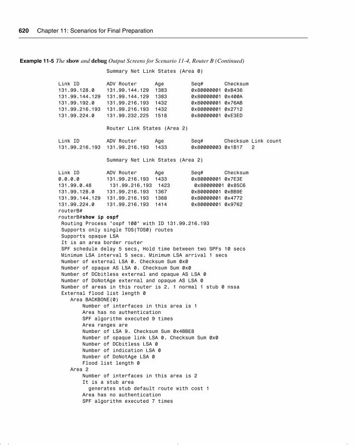
620 Chapter 11: Scenarios for Final Preparation
Summary Net Link States (Area 0) Link ID ADV Router Age Seq# Checksum131.99.128.0 131.99.144.129 1383 0x80000001 0xB436131.99.144.129 131.99.144.129 1383 0x80000001 0x400A131.99.192.0 131.99.216.193 1432 0x80000001 0x76AB131.99.216.193 131.99.216.193 1432 0x80000001 0x2712131.99.224.0 131.99.232.225 1518 0x80000001 0xE3ED Router Link States (Area 2) Link ID ADV Router Age Seq# Checksum Link count131.99.216.193 131.99.216.193 1433 0x80000003 0x1B17 2 Summary Net Link States (Area 2) Link ID ADV Router Age Seq# Checksum0.0.0.0 131.99.216.193 1433 0x80000001 0x7E3E131.99.0.48 131.99.216.193 1423 0x80000001 0x85C6131.99.128.0 131.99.216.193 1367 0x80000001 0xBB9E131.99.144.129 131.99.216.193 1368 0x80000001 0x4772131.99.224.0 131.99.216.193 1414 0x80000001 0x9762routerB#routerB#show ip ospf Routing Process "ospf 100" with ID 131.99.216.193 Supports only single TOS(TOS0) routes Supports opaque LSA It is an area border router SPF schedule delay 5 secs, Hold time between two SPFs 10 secs Minimum LSA interval 5 secs. Minimum LSA arrival 1 secs Number of external LSA 0. Checksum Sum 0x0 Number of opaque AS LSA 0. Checksum Sum 0x0 Number of DCbitless external and opaque AS LSA 0 Number of DoNotAge external and opaque AS LSA 0 Number of areas in this router is 2. 1 normal 1 stub 0 nssa External flood list length 0 Area BACKBONE(0) Number of interfaces in this area is 1 Area has no authentication SPF algorithm executed 9 times Area ranges are Number of LSA 9. Checksum Sum 0x4BBE8 Number of opaque link LSA 0. Checksum Sum 0x0 Number of DCbitless LSA 0 Number of indication LSA 0 Number of DoNotAge LSA 0 Flood list length 0 Area 2 Number of interfaces in this area is 2 It is a stub area generates stub default route with cost 1 Area has no authentication SPF algorithm executed 7 times
Example 11-5 The show and debug Output Screens for Scenario 11-4, Router B (Continued)
chpt_01.book Page 620 Thursday, December 21, 2000 6:22 PM
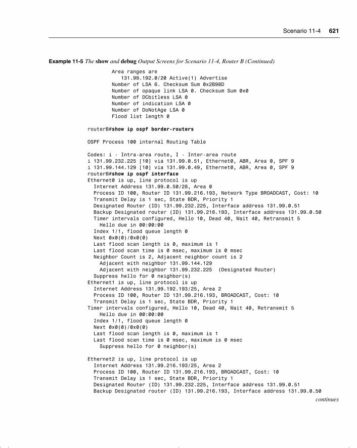
Scenario 11-4 621
Area ranges are 131.99.192.0/20 Active(1) Advertise Number of LSA 6. Checksum Sum 0x2B98D Number of opaque link LSA 0. Checksum Sum 0x0 Number of DCbitless LSA 0 Number of indication LSA 0 Number of DoNotAge LSA 0 Flood list length 0 routerB#show ip ospf border-routers OSPF Process 100 internal Routing Table Codes: i - Intra-area route, I - Inter-area route i 131.99.232.225 [10] via 131.99.0.51, Ethernet0, ABR, Area 0, SPF 9i 131.99.144.129 [10] via 131.99.0.49, Ethernet0, ABR, Area 0, SPF 9routerB#show ip ospf interfaceEthernet0 is up, line protocol is up Internet Address 131.99.0.50/28, Area 0 Process ID 100, Router ID 131.99.216.193, Network Type BROADCAST, Cost: 10 Transmit Delay is 1 sec, State BDR, Priority 1 Designated Router (ID) 131.99.232.225, Interface address 131.99.0.51 Backup Designated router (ID) 131.99.216.193, Interface address 131.99.0.50 Timer intervals configured, Hello 10, Dead 40, Wait 40, Retransmit 5 Hello due in 00:00:00 Index 1/1, flood queue length 0 Next 0x0(0)/0x0(0) Last flood scan length is 0, maximum is 1 Last flood scan time is 0 msec, maximum is 0 msec Neighbor Count is 2, Adjacent neighbor count is 2 Adjacent with neighbor 131.99.144.129 Adjacent with neighbor 131.99.232.225 (Designated Router) Suppress hello for 0 neighbor(s)Ethernet1 is up, line protocol is up Internet Address 131.99.192.193/25, Area 2 Process ID 100, Router ID 131.99.216.193, BROADCAST, Cost: 10 Transmit Delay is 1 sec, State BDR, Priority 1Timer intervals configured, Hello 10, Dead 40, Wait 40, Retransmit 5 Hello due in 00:00:00 Index 1/1, flood queue length 0 Next 0x0(0)/0x0(0) Last flood scan length is 0, maximum is 1 Last flood scan time is 0 msec, maximum is 0 msec Suppress hello for 0 neighbor(s)
Ethernet2 is up, line protocol is up Internet Address 131.99.216.193/25, Area 2 Process ID 100, Router ID 131.99.216.193, BROADCAST, Cost: 10 Transmit Delay is 1 sec, State BDR, Priority 1 Designated Router (ID) 131.99.232.225, Interface address 131.99.0.51 Backup Designated router (ID) 131.99.216.193, Interface address 131.99.0.50
continues
Example 11-5 The show and debug Output Screens for Scenario 11-4, Router B (Continued)
chpt_01.book Page 621 Thursday, December 21, 2000 6:22 PM

622 Chapter 11: Scenarios for Final Preparation
Timer intervals configured, Hello 10, Dead 40, Wait 40, Retransmit 5 Hello due in 00:00:00 Index 1/1, flood queue length 0 Next 0x0(0)/0x0(0) Last flood scan length is 0, maximum is 1 Last flood scan time is 0 msec, maximum is 0 msec Suppress hello for 0 neighbor(s)
routerB# show ip ospf interfaceEthernet0 is up, line protocol is up Internet Address 131.99.0.50/28, Area 0 Process ID 100, Router ID 131.99.216.193, Network Type BROADCAST, Cost: 10 Transmit Delay is 1 sec, State BDR, Priority 1 Designated Router (ID) 131.99.232.225, Interface address 131.99.0.51 Backup Designated router (ID) 131.99.216.193, Interface address 131.99.0.50 Timer intervals configured, Hello 10, Dead 40, Wait 40, Retransmit 5 Hello due in 00:00:06 Index 1/1, flood queue length 0 Next 0x0(0)/0x0(0) Last flood scan length is 0, maximum is 1 Last flood scan time is 0 msec, maximum is 0 msec Neighbor Count is 2, Adjacent neighbor count is 2 Adjacent with neighbor 131.99.144.129 Adjacent with neighbor 131.99.232.225 (Designated Router) Suppress hello for 0 neighbor(s)Ethernet1 is up, line protocol is up Internet Address 131.99.192.193/25, Area 2 Process ID 100, Router ID 131.99.216.193, BROADCAST, Cost: 10 Transmit Delay is 1 sec, State BDR, Priority 1Timer intervals configured, Hello 10, Dead 40, Wait 40, Retransmit 5 Hello due in 00:00:06 Index 1/1, flood queue length 0 Next 0x0(0)/0x0(0) Last flood scan length is 0, maximum is 1 Last flood scan time is 0 msec, maximum is 0 msecSuppress hello for 0 neighbor(s)
Ethernet2 is up, line protocol is up Internet Address 131.99.216.193/25, Area 2 Process ID 100, Router ID 131.99.216.193 BROADCAST, Cost: 10 Transmit Delay is 1 sec, State BDR, Priority 1Timer intervals configured, Hello 10, Dead 40, Wait 40, Retransmit 5 Hello due in 00:00:06 Index 1/1, flood queue length 0 Next 0x0(0)/0x0(0) Last flood scan length is 0, maximum is 1 Last flood scan time is 0 msec, maximum is 0 msecSuppress hello for 0 neighbor(s)
routerB# show ip ospf neighbors
Example 11-5 The show and debug Output Screens for Scenario 11-4, Router B (Continued)
chpt_01.book Page 622 Thursday, December 21, 2000 6:22 PM
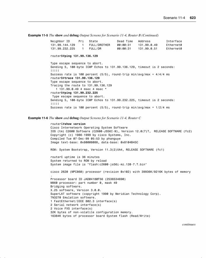
Scenario 11-4 623
Neighbor ID Pri State Dead Time Address Interface131.99.144.129 1 FULL/DROTHER 00:00:31 131.99.0.49 Ethernet0131.99.232.225 1 FULL/DR 00:00:31 131.99.0.51 Ethernet0
routerB#ping 131.99.136.129 Type escape sequence to abort.Sending 5, 100-byte ICMP Echos to 131.99.136.129, timeout is 2 seconds:!!!!!Success rate is 100 percent (5/5), round-trip min/avg/max = 4/4/4 msrouterB#trace 131.99.136.129Type escape sequence to abort.Tracing the route to 131.99.136.129 1 131.99.0.49 4 msec 4 msec *routerB#ping 131.99.232.225 Type escape sequence to abort.Sending 5, 100-byte ICMP Echos to 131.99.232.225, timeout is 2 seconds:!!!!!Success rate is 100 percent (5/5), round-trip min/avg/max = 1/2/4 ms
Example 11-6 The show and debug Output Screens for Scenario 11-4, Router C
routerC#show versionCisco Internetwork Operating System SoftwareIOS (tm) C2600 Software (C2600-JS56I-M), Version 12.0(7)T, RELEASE SOFTWARE (fc2)Copyright (c) 1986-1999 by cisco Systems, Inc.Compiled Tue 07-Dec-99 05:53 by phanguyeImage text-base: 0x80008088, data-base: 0x8104B45C ROM: System Bootstrap, Version 11.3(2)XA4, RELEASE SOFTWARE (fc1) routerC uptime is 36 minutesSystem returned to ROM by reloadSystem image file is "flash:c2600-js56i-mz.120-7.T.bin" cisco 2620 (MPC860) processor (revision 0x102) with 39936K/9216K bytes of memory.Processor board ID JAD04180F56 (2536534690)M860 processor: part number 0, mask 49Bridging software.X.25 software, Version 3.0.0.SuperLAT software (copyright 1990 by Meridian Technology Corp).TN3270 Emulation software.1 FastEthernet/IEEE 802.3 interface(s)2 Serial network interface(s)2 Voice FXS interface(s)32K bytes of non-volatile configuration memory.16384K bytes of processor board System flash (Read/Write)
continues
Example 11-5 The show and debug Output Screens for Scenario 11-4, Router B (Continued)
chpt_01.book Page 623 Thursday, December 21, 2000 6:22 PM
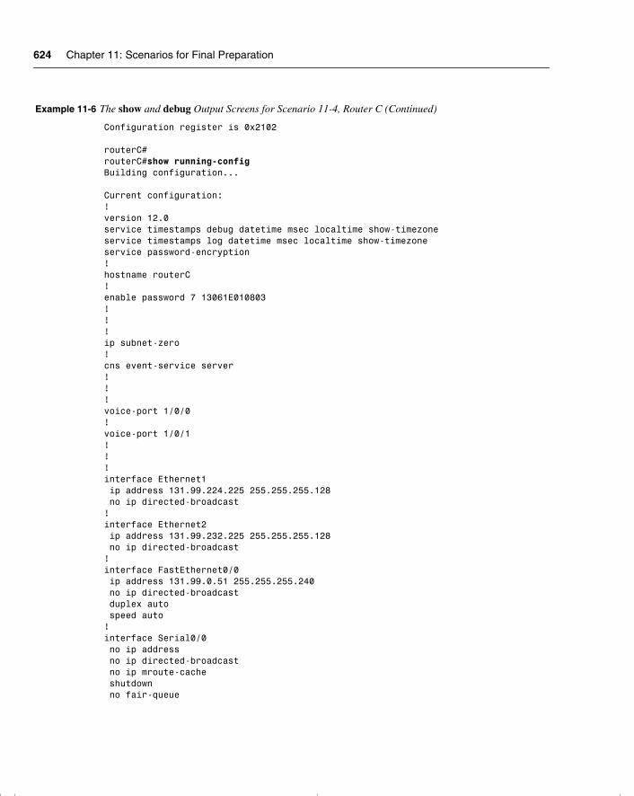
624 Chapter 11: Scenarios for Final Preparation
Configuration register is 0x2102 routerC#routerC#show running-configBuilding configuration... Current configuration:!version 12.0service timestamps debug datetime msec localtime show-timezoneservice timestamps log datetime msec localtime show-timezoneservice password-encryption!hostname routerC!enable password 7 13061E010803!!!ip subnet-zero!cns event-service server!!!voice-port 1/0/0!voice-port 1/0/1!!!interface Ethernet1 ip address 131.99.224.225 255.255.255.128 no ip directed-broadcast!interface Ethernet2 ip address 131.99.232.225 255.255.255.128 no ip directed-broadcast!interface FastEthernet0/0 ip address 131.99.0.51 255.255.255.240 no ip directed-broadcast duplex auto speed auto!interface Serial0/0 no ip address no ip directed-broadcast no ip mroute-cache shutdown no fair-queue
Example 11-6 The show and debug Output Screens for Scenario 11-4, Router C (Continued)
chpt_01.book Page 624 Thursday, December 21, 2000 6:22 PM

Scenario 11-4 625
!interface Serial0/1 no ip address no ip directed-broadcast shutdown!router ospf 100 area 3 stub area 3 range 131.99.224.0 255.255.240.0 network 131.99.0.51 0.0.0.0 area 0 network 0.0.0.0 255.255.255.255 area 3!ip classlessno ip http server!!!line con 0 transport input noneline aux 0line vty 0 4 password 7 00071A150754 login!no scheduler allocateend routerC# show interfaceFastEthernet0/0 is up, line protocol is up Hardware is AmdFE, address is 0002.16bb.2fe0 (bia 0002.16bb.2fe0) Internet address is 131.99.0.51/28 MTU 1500 bytes, BW 100000 Kbit, DLY 100 usec, reliability 255/255, txload 1/255, rxload 1/255 Encapsulation ARPA, loopback not set Keepalive set (10 sec) Full-duplex, 100Mb/s, 100BaseTX/FX ARP type: ARPA, ARP Timeout 04:00:00 Last input 00:00:05, output 00:00:03, output hang never Last clearing of "show interface" counters never Queueing strategy: fifoOutput queue 0/40, 0 drops; input queue 0/75, 0 drops 5 minute input rate 0 bits/sec, 0 packets/sec 5 minute output rate 0 bits/sec, 0 packets/sec 408 packets input, 36008 bytes Received 395 broadcasts, 0 runts, 0 giants, 0 throttles 0 input errors, 0 CRC, 0 frame, 0 overrun, 0 ignored 0 watchdog, 0 multicast 0 input packets with dribble condition detected 438 packets output, 52473 bytes, 0 underruns 0 output errors, 0 collisions, 1 interface resets 0 babbles, 0 late collision, 0 deferred 0 lost carrier, 0 no carrier 0 output buffer failures, 0 output buffers swapped out
continues
Example 11-6 The show and debug Output Screens for Scenario 11-4, Router C (Continued)
chpt_01.book Page 625 Thursday, December 21, 2000 6:22 PM
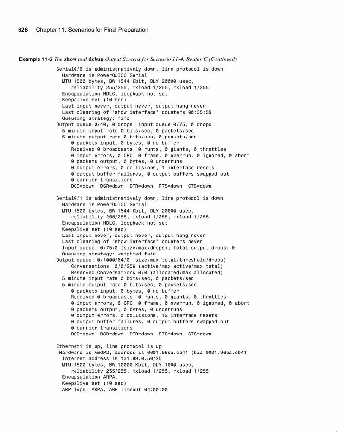
626 Chapter 11: Scenarios for Final Preparation
Serial0/0 is administratively down, line protocol is down Hardware is PowerQUICC Serial MTU 1500 bytes, BW 1544 Kbit, DLY 20000 usec, reliability 255/255, txload 1/255, rxload 1/255 Encapsulation HDLC, loopback not set Keepalive set (10 sec) Last input never, output never, output hang never Last clearing of "show interface" counters 00:35:55 Queueing strategy: fifoOutput queue 0/40, 0 drops; input queue 0/75, 0 drops 5 minute input rate 0 bits/sec, 0 packets/sec 5 minute output rate 0 bits/sec, 0 packets/sec 0 packets input, 0 bytes, 0 no buffer Received 0 broadcasts, 0 runts, 0 giants, 0 throttles 0 input errors, 0 CRC, 0 frame, 0 overrun, 0 ignored, 0 abort 0 packets output, 0 bytes, 0 underruns 0 output errors, 0 collisions, 1 interface resets 0 output buffer failures, 0 output buffers swapped out 0 carrier transitions DCD=down DSR=down DTR=down RTS=down CTS=down Serial0/1 is administratively down, line protocol is down Hardware is PowerQUICC Serial MTU 1500 bytes, BW 1544 Kbit, DLY 20000 usec, reliability 255/255, txload 1/255, rxload 1/255 Encapsulation HDLC, loopback not set Keepalive set (10 sec) Last input never, output never, output hang never Last clearing of "show interface" counters never Input queue: 0/75/0 (size/max/drops); Total output drops: 0 Queueing strategy: weighted fairOutput queue: 0/1000/64/0 (size/max total/threshold/drops) Conversations 0/0/256 (active/max active/max total) Reserved Conversations 0/0 (allocated/max allocated) 5 minute input rate 0 bits/sec, 0 packets/sec 5 minute output rate 0 bits/sec, 0 packets/sec 0 packets input, 0 bytes, 0 no buffer Received 0 broadcasts, 0 runts, 0 giants, 0 throttles 0 input errors, 0 CRC, 0 frame, 0 overrun, 0 ignored, 0 abort 0 packets output, 0 bytes, 0 underruns 0 output errors, 0 collisions, 12 interface resets 0 output buffer failures, 0 output buffers swapped out 0 carrier transitions DCD=down DSR=down DTR=down RTS=down CTS=down Ethernet1 is up, line protocol is up Hardware is AmdP2, address is 0001.96ea.ca41 (bia 0001.96ea.cb41) Internet address is 131.99.0.50/25 MTU 1500 bytes, BW 10000 Kbit, DLY 1000 usec, reliability 255/255, txload 1/255, rxload 1/255 Encapsulation ARPA, Keepalive set (10 sec) ARP type: ARPA, ARP Timeout 04:00:00
Example 11-6 The show and debug Output Screens for Scenario 11-4, Router C (Continued)
chpt_01.book Page 626 Thursday, December 21, 2000 6:22 PM
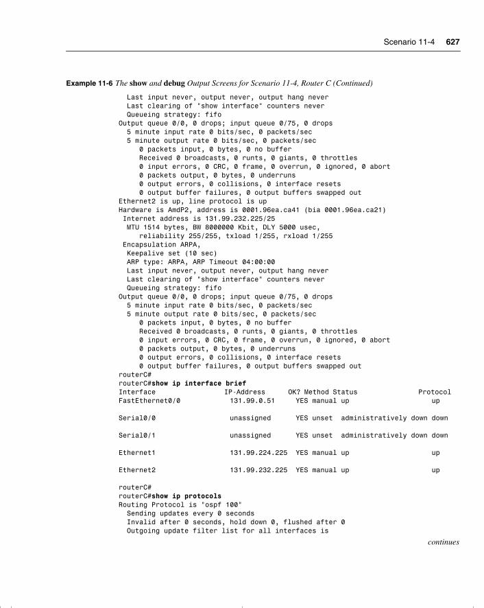
Scenario 11-4 627
Last input never, output never, output hang never Last clearing of "show interface" counters never Queueing strategy: fifoOutput queue 0/0, 0 drops; input queue 0/75, 0 drops 5 minute input rate 0 bits/sec, 0 packets/sec 5 minute output rate 0 bits/sec, 0 packets/sec 0 packets input, 0 bytes, 0 no buffer Received 0 broadcasts, 0 runts, 0 giants, 0 throttles 0 input errors, 0 CRC, 0 frame, 0 overrun, 0 ignored, 0 abort 0 packets output, 0 bytes, 0 underruns 0 output errors, 0 collisions, 0 interface resets 0 output buffer failures, 0 output buffers swapped outEthernet2 is up, line protocol is upHardware is AmdP2, address is 0001.96ea.ca41 (bia 0001.96ea.ca21) Internet address is 131.99.232.225/25 MTU 1514 bytes, BW 8000000 Kbit, DLY 5000 usec, reliability 255/255, txload 1/255, rxload 1/255 Encapsulation ARPA, Keepalive set (10 sec) ARP type: ARPA, ARP Timeout 04:00:00 Last input never, output never, output hang never Last clearing of "show interface" counters never Queueing strategy: fifoOutput queue 0/0, 0 drops; input queue 0/75, 0 drops 5 minute input rate 0 bits/sec, 0 packets/sec 5 minute output rate 0 bits/sec, 0 packets/sec 0 packets input, 0 bytes, 0 no buffer Received 0 broadcasts, 0 runts, 0 giants, 0 throttles 0 input errors, 0 CRC, 0 frame, 0 overrun, 0 ignored, 0 abort 0 packets output, 0 bytes, 0 underruns 0 output errors, 0 collisions, 0 interface resets 0 output buffer failures, 0 output buffers swapped outrouterC#routerC#show ip interface briefInterface IP-Address OK? Method Status ProtocolFastEthernet0/0 131.99.0.51 YES manual up up Serial0/0 unassigned YES unset administratively down down Serial0/1 unassigned YES unset administratively down down Ethernet1 131.99.224.225 YES manual up up Ethernet2 131.99.232.225 YES manual up up routerC#routerC#show ip protocolsRouting Protocol is "ospf 100" Sending updates every 0 seconds Invalid after 0 seconds, hold down 0, flushed after 0 Outgoing update filter list for all interfaces is
continues
Example 11-6 The show and debug Output Screens for Scenario 11-4, Router C (Continued)
chpt_01.book Page 627 Thursday, December 21, 2000 6:22 PM
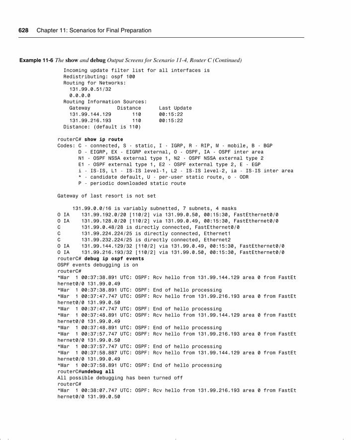
628 Chapter 11: Scenarios for Final Preparation
Incoming update filter list for all interfaces is Redistributing: ospf 100 Routing for Networks: 131.99.0.51/32 0.0.0.0 Routing Information Sources: Gateway Distance Last Update 131.99.144.129 110 00:15:22 131.99.216.193 110 00:15:22 Distance: (default is 110) routerC# show ip routeCodes: C - connected, S - static, I - IGRP, R - RIP, M - mobile, B - BGP D - EIGRP, EX - EIGRP external, O - OSPF, IA - OSPF inter area N1 - OSPF NSSA external type 1, N2 - OSPF NSSA external type 2 E1 - OSPF external type 1, E2 - OSPF external type 2, E - EGP i - IS-IS, L1 - IS-IS level-1, L2 - IS-IS level-2, ia - IS-IS inter area * - candidate default, U - per-user static route, o - ODR P - periodic downloaded static route Gateway of last resort is not set 131.99.0.0/16 is variably subnetted, 7 subnets, 4 masksO IA 131.99.192.0/20 [110/2] via 131.99.0.50, 00:15:30, FastEthernet0/0O IA 131.99.128.0/20 [110/2] via 131.99.0.49, 00:15:30, FastEthernet0/0C 131.99.0.48/28 is directly connected, FastEthernet0/0C 131.99.224.224/25 is directly connected, Ethernet1C 131.99.232.224/25 is directly connected, Ethernet2O IA 131.99.144.129/32 [110/2] via 131.99.0.49, 00:15:30, FastEthernet0/0O IA 131.99.216.193/32 [110/2] via 131.99.0.50, 00:15:30, FastEthernet0/0routerC# debug ip ospf eventsOSPF events debugging is onrouterC#*Mar 1 00:37:38.891 UTC: OSPF: Rcv hello from 131.99.144.129 area 0 from FastEthernet0/0 131.99.0.49*Mar 1 00:37:38.891 UTC: OSPF: End of hello processing*Mar 1 00:37:47.747 UTC: OSPF: Rcv hello from 131.99.216.193 area 0 from FastEthernet0/0 131.99.0.50*Mar 1 00:37:47.747 UTC: OSPF: End of hello processing*Mar 1 00:37:48.891 UTC: OSPF: Rcv hello from 131.99.144.129 area 0 from FastEthernet0/0 131.99.0.49*Mar 1 00:37:48.891 UTC: OSPF: End of hello processing*Mar 1 00:37:57.747 UTC: OSPF: Rcv hello from 131.99.216.193 area 0 from FastEthernet0/0 131.99.0.50*Mar 1 00:37:57.747 UTC: OSPF: End of hello processing*Mar 1 00:37:58.887 UTC: OSPF: Rcv hello from 131.99.144.129 area 0 from FastEthernet0/0 131.99.0.49*Mar 1 00:37:58.891 UTC: OSPF: End of hello processingrouterC#undebug allAll possible debugging has been turned offrouterC#*Mar 1 00:38:07.747 UTC: OSPF: Rcv hello from 131.99.216.193 area 0 from FastEthernet0/0 131.99.0.50
Example 11-6 The show and debug Output Screens for Scenario 11-4, Router C (Continued)
chpt_01.book Page 628 Thursday, December 21, 2000 6:22 PM
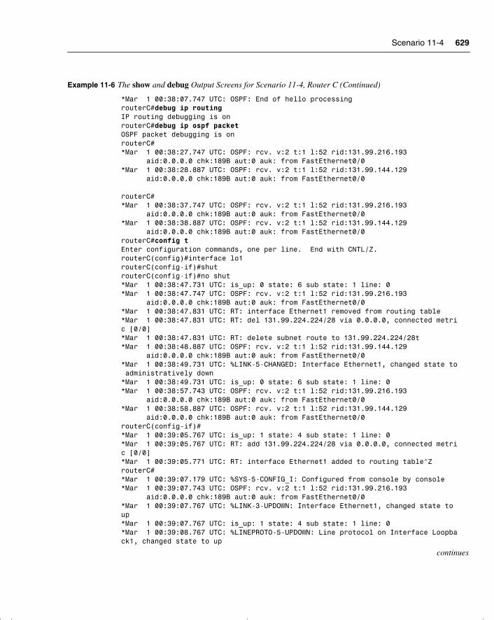
Scenario 11-4 629
*Mar 1 00:38:07.747 UTC: OSPF: End of hello processingrouterC#debug ip routingIP routing debugging is onrouterC#debug ip ospf packetOSPF packet debugging is onrouterC#*Mar 1 00:38:27.747 UTC: OSPF: rcv. v:2 t:1 l:52 rid:131.99.216.193 aid:0.0.0.0 chk:189B aut:0 auk: from FastEthernet0/0*Mar 1 00:38:28.887 UTC: OSPF: rcv. v:2 t:1 l:52 rid:131.99.144.129 aid:0.0.0.0 chk:189B aut:0 auk: from FastEthernet0/0 routerC#*Mar 1 00:38:37.747 UTC: OSPF: rcv. v:2 t:1 l:52 rid:131.99.216.193 aid:0.0.0.0 chk:189B aut:0 auk: from FastEthernet0/0*Mar 1 00:38:38.887 UTC: OSPF: rcv. v:2 t:1 l:52 rid:131.99.144.129 aid:0.0.0.0 chk:189B aut:0 auk: from FastEthernet0/0routerC#config tEnter configuration commands, one per line. End with CNTL/Z.routerC(config)#interface lo1routerC(config-if)#shutrouterC(config-if)#no shut*Mar 1 00:38:47.731 UTC: is_up: 0 state: 6 sub state: 1 line: 0*Mar 1 00:38:47.747 UTC: OSPF: rcv. v:2 t:1 l:52 rid:131.99.216.193 aid:0.0.0.0 chk:189B aut:0 auk: from FastEthernet0/0*Mar 1 00:38:47.831 UTC: RT: interface Ethernet1 removed from routing table*Mar 1 00:38:47.831 UTC: RT: del 131.99.224.224/28 via 0.0.0.0, connected metric [0/0]*Mar 1 00:38:47.831 UTC: RT: delete subnet route to 131.99.224.224/28t*Mar 1 00:38:48.887 UTC: OSPF: rcv. v:2 t:1 l:52 rid:131.99.144.129 aid:0.0.0.0 chk:189B aut:0 auk: from FastEthernet0/0*Mar 1 00:38:49.731 UTC: %LINK-5-CHANGED: Interface Ethernet1, changed state to administratively down*Mar 1 00:38:49.731 UTC: is_up: 0 state: 6 sub state: 1 line: 0*Mar 1 00:38:57.743 UTC: OSPF: rcv. v:2 t:1 l:52 rid:131.99.216.193 aid:0.0.0.0 chk:189B aut:0 auk: from FastEthernet0/0*Mar 1 00:38:58.887 UTC: OSPF: rcv. v:2 t:1 l:52 rid:131.99.144.129 aid:0.0.0.0 chk:189B aut:0 auk: from FastEthernet0/0routerC(config-if)#*Mar 1 00:39:05.767 UTC: is_up: 1 state: 4 sub state: 1 line: 0*Mar 1 00:39:05.767 UTC: RT: add 131.99.224.224/28 via 0.0.0.0, connected metric [0/0]*Mar 1 00:39:05.771 UTC: RT: interface Ethernet1 added to routing table^ZrouterC#*Mar 1 00:39:07.179 UTC: %SYS-5-CONFIG_I: Configured from console by console*Mar 1 00:39:07.743 UTC: OSPF: rcv. v:2 t:1 l:52 rid:131.99.216.193 aid:0.0.0.0 chk:189B aut:0 auk: from FastEthernet0/0*Mar 1 00:39:07.767 UTC: %LINK-3-UPDOWN: Interface Ethernet1, changed state toup*Mar 1 00:39:07.767 UTC: is_up: 1 state: 4 sub state: 1 line: 0*Mar 1 00:39:08.767 UTC: %LINEPROTO-5-UPDOWN: Line protocol on Interface Loopback1, changed state to up
continues
Example 11-6 The show and debug Output Screens for Scenario 11-4, Router C (Continued)
chpt_01.book Page 629 Thursday, December 21, 2000 6:22 PM
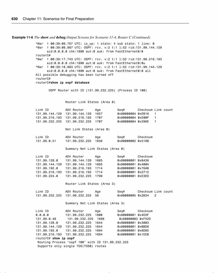
630 Chapter 11: Scenarios for Final Preparation
*Mar 1 00:39:08.767 UTC: is_up: 1 state: 4 sub state: 1 line: 0*Mar 1 00:39:08.887 UTC: OSPF: rcv. v:2 t:1 l:52 rid:131.99.144.129 aid:0.0.0.0 chk:189B aut:0 auk: from FastEthernet0/0routerC#*Mar 1 00:39:17.743 UTC: OSPF: rcv. v:2 t:1 l:52 rid:131.99.216.193 aid:0.0.0.0 chk:189B aut:0 auk: from FastEthernet0/0u*Mar 1 00:39:18.883 UTC: OSPF: rcv. v:2 t:1 l:52 rid:131.99.144.129 aid:0.0.0.0 chk:189B aut:0 auk: from FastEthernet0/0 allAll possible debugging has been turned offrouterC#routerC#show ip ospf database OSPF Router with ID (131.99.232.225) (Process ID 100) Router Link States (Area 0) Link ID ADV Router Age Seq# Checksum Link count131.99.144.129 131.99.144.129 1657 0x80000004 0xEB16 1131.99.216.193 131.99.216.193 1707 0x80000004 0xE00F 1131.99.232.225 131.99.232.225 1707 0x80000004 0x296E 1 Net Link States (Area 0) Link ID ADV Router Age Seq# Checksum131.99.0.51 131.99.232.225 1656 0x80000002 0x516B Summary Net Link States (Area 0) Link ID ADV Router Age Seq# Checksum131.99.128.0 131.99.144.129 1665 0x80000001 0xB436131.99.144.129 131.99.144.129 1665 0x80000001 0x400A131.99.192.0 131.99.216.193 1714 0x80000001 0x76AB131.99.216.193 131.99.216.193 1714 0x80000001 0x2712131.99.224.0 131.99.232.225 1799 0x80000001 0xE3ED Router Link States (Area 3) Link ID ADV Router Age Seq# Checksum Link count131.99.232.225 131.99.232.225 56 0x80000005 0x2B34 2 Summary Net Link States (Area 3) Link ID ADV Router Age Seq# Checksum0.0.0.0 131.99.232.225 1800 0x80000001 0x4D3F131.99.0.48 131.99.232.225 1698 0x80000003 0xF52D131.99.128.0 131.99.232.225 1644 0x80000001 0x3003131.99.144.129 131.99.232.225 1644 0x80000001 0xBBD6131.99.192.0 131.99.232.225 1694 0x80000001 0x6D85131.99.216.193 131.99.232.225 1694 0x80000001 0x1EEBrouterC# show ip ospf Routing Process "ospf 100" with ID 131.99.232.225 Supports only single TOS(TOS0) routes
Example 11-6 The show and debug Output Screens for Scenario 11-4, Router C (Continued)
chpt_01.book Page 630 Thursday, December 21, 2000 6:22 PM
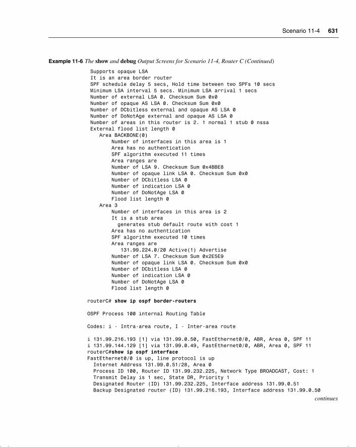
Scenario 11-4 631
Supports opaque LSA It is an area border router SPF schedule delay 5 secs, Hold time between two SPFs 10 secs Minimum LSA interval 5 secs. Minimum LSA arrival 1 secs Number of external LSA 0. Checksum Sum 0x0 Number of opaque AS LSA 0. Checksum Sum 0x0 Number of DCbitless external and opaque AS LSA 0 Number of DoNotAge external and opaque AS LSA 0 Number of areas in this router is 2. 1 normal 1 stub 0 nssa External flood list length 0 Area BACKBONE(0) Number of interfaces in this area is 1 Area has no authentication SPF algorithm executed 11 times Area ranges are Number of LSA 9. Checksum Sum 0x4BBE8 Number of opaque link LSA 0. Checksum Sum 0x0 Number of DCbitless LSA 0 Number of indication LSA 0 Number of DoNotAge LSA 0 Flood list length 0 Area 3 Number of interfaces in this area is 2 It is a stub area generates stub default route with cost 1 Area has no authentication SPF algorithm executed 10 times Area ranges are 131.99.224.0/20 Active(1) Advertise Number of LSA 7. Checksum Sum 0x2E5E9 Number of opaque link LSA 0. Checksum Sum 0x0 Number of DCbitless LSA 0 Number of indication LSA 0 Number of DoNotAge LSA 0 Flood list length 0 routerC# show ip ospf border-routers OSPF Process 100 internal Routing Table Codes: i - Intra-area route, I - Inter-area route i 131.99.216.193 [1] via 131.99.0.50, FastEthernet0/0, ABR, Area 0, SPF 11i 131.99.144.129 [1] via 131.99.0.49, FastEthernet0/0, ABR, Area 0, SPF 11routerC#show ip ospf interfaceFastEthernet0/0 is up, line protocol is up Internet Address 131.99.0.51/28, Area 0 Process ID 100, Router ID 131.99.232.225, Network Type BROADCAST, Cost: 1 Transmit Delay is 1 sec, State DR, Priority 1 Designated Router (ID) 131.99.232.225, Interface address 131.99.0.51 Backup Designated router (ID) 131.99.216.193, Interface address 131.99.0.50
continues
Example 11-6 The show and debug Output Screens for Scenario 11-4, Router C (Continued)
chpt_01.book Page 631 Thursday, December 21, 2000 6:22 PM
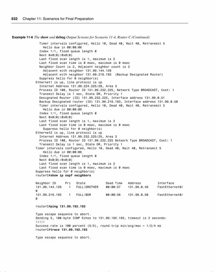
632 Chapter 11: Scenarios for Final Preparation
Timer intervals configured, Hello 10, Dead 40, Wait 40, Retransmit 5 Hello due in 00:00:06 Index 1/1, flood queue length 0 Next 0x0(0)/0x0(0) Last flood scan length is 1, maximum is 2 Last flood scan time is 0 msec, maximum is 0 msec Neighbor Count is 2, Adjacent neighbor count is 2 Adjacent with neighbor 131.99.144.129 Adjacent with neighbor 131.99.216.193 (Backup Designated Router) Suppress hello for 0 neighbor(s)Ethernet1 is up, line protocol is up Internet Address 131.99.224.225/28, Area 3 Process ID 100, Router ID 131.99.232.225, Network Type BROADCAST, Cost: 1 Transmit Delay is 1 sec, State DR, Priority 1 Designated Router (ID) 131.99.232.225, Interface address 131.99.0.51 Backup Designated router (ID) 131.99.216.193, Interface address 131.99.0.50 Timer intervals configured, Hello 10, Dead 40, Wait 40, Retransmit 5 Hello due in 00:00:06 Index 1/1, flood queue length 0 Next 0x0(0)/0x0(0) Last flood scan length is 1, maximum is 2 Last flood scan time is 0 msec, maximum is 0 msec Suppress hello for 0 neighbor(s)Ethernet2 is up, line protocol is up Internet Address 131.99.232.225/25, Area 3 Process ID 100, Router ID 131.99.232.225 Network Type BROADCAST, Cost: 1 Transmit Delay is 1 sec, State DR, Priority 1Timer intervals configured, Hello 10, Dead 40, Wait 40, Retransmit 5 Hello due in 00:00:06 Index 1/1, flood queue length 0 Next 0x0(0)/0x0(0) Last flood scan length is 1, maximum is 2 Last flood scan time is 0 msec, maximum is 0 msecSuppress hello for 0 neighbor(s)routerC#show ip ospf neighbors Neighbor ID Pri State Dead Time Address Interface131.99.144.129 1 FULL/DROTHER 00:00:37 131.99.0.49 FastEthernet0/0131.99.216.193 1 FULL/BDR 00:00:36 131.99.0.50 FastEthernet0/0
routerC#ping 131.99.192.193 Type escape sequence to abort.Sending 5, 100-byte ICMP Echos to 131.99.192.193, timeout is 2 seconds:!!!!!Success rate is 100 percent (5/5), round-trip min/avg/max = 1/2/4 msrouterC#trace 131.99.192.193 Type escape sequence to abort.
Example 11-6 The show and debug Output Screens for Scenario 11-4, Router C (Continued)
chpt_01.book Page 632 Thursday, December 21, 2000 6:22 PM
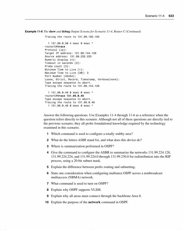
Scenario 11-4 633
Answer the following questions. Use Examples 11-4 through 11-6 as a reference when the question refers directly to this scenario. Although not all of these questions are directly tied to the previous scenario, they all probe foundational knowledge required by the technology examined in this scenario.
1 Which command is used to configure a totally stubby area?
2 What do the letters ASBR stand for, and what does this device do?
3 Where is summarization performed in OSPF?
4 Give the command to configure the ASBR to summarize the networks 131.99.224.128, 131.99.224.224, and 131.99.224.0 through 131.99.230.0 for redistribution into the RIP process, using a 20-bit subnet mask.
5 Explain the difference between prefix routing and subnetting.
6 State one consideration when configuring multiarea OSPF across a nonbroadcast multiaccess (NBMA) network.
7 What command is used to turn on OSPF?
8 Explain why OSPF supports VLSM.
9 Explain why all areas must connect through the backbone Area 0.
10 Explain the purpose of the network command in OSPF.
Tracing the route to 131.99.192.193 1 131.99.0.50 4 msec 0 msec *routerC#traceProtocol [ip]:Target IP address: 131.99.144.129Source address: 131.99.232.225Numeric display [n]:Timeout in seconds [3]:Probe count [3]:Minimum Time to Live [1]:Maximum Time to Live [30]: 3Port Number [33434]:Loose, Strict, Record, Timestamp, Verbose[none]:Type escape sequence to abort.Tracing the route to 131.99.144.129 1 131.99.0.49 0 msec 0 msec *routerC#trace 131.99.0.49Type escape sequence to abort.Tracing the route to 131.99.0.49 1 131.99.0.49 0 msec 0 msec *
Example 11-6 The show and debug Output Screens for Scenario 11-4, Router C (Continued)
chpt_01.book Page 633 Thursday, December 21, 2000 6:22 PM
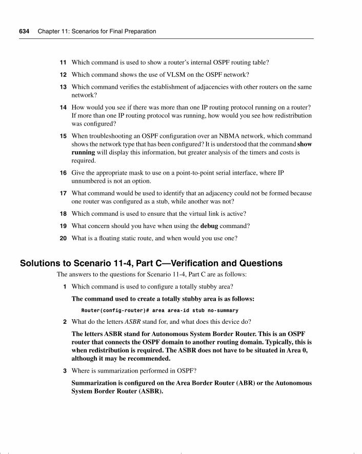
634 Chapter 11: Scenarios for Final Preparation
11 Which command is used to show a router’s internal OSPF routing table?
12 Which command shows the use of VLSM on the OSPF network?
13 Which command verifies the establishment of adjacencies with other routers on the same network?
14 How would you see if there was more than one IP routing protocol running on a router? If more than one IP routing protocol was running, how would you see how redistribution was configured?
15 When troubleshooting an OSPF configuration over an NBMA network, which command shows the network type that has been configured? It is understood that the command show running will display this information, but greater analysis of the timers and costs is required.
16 Give the appropriate mask to use on a point-to-point serial interface, where IP unnumbered is not an option.
17 What command would be used to identify that an adjacency could not be formed because one router was configured as a stub, while another was not?
18 Which command is used to ensure that the virtual link is active?
19 What concern should you have when using the debug command?
20 What is a floating static route, and when would you use one?
Solutions to Scenario 11-4, Part C—Verification and QuestionsThe answers to the questions for Scenario 11-4, Part C are as follows:
1 Which command is used to configure a totally stubby area?
The command used to create a totally stubby area is as follows:
Router(config-router)# area area-id stub no-summary
2 What do the letters ASBR stand for, and what does this device do?
The letters ASBR stand for Autonomous System Border Router. This is an OSPF router that connects the OSPF domain to another routing domain. Typically, this is when redistribution is required. The ASBR does not have to be situated in Area 0, although it may be recommended.
3 Where is summarization performed in OSPF?
Summarization is configured on the Area Border Router (ABR) or the Autonomous System Border Router (ASBR).
chpt_01.book Page 634 Thursday, December 21, 2000 6:22 PM
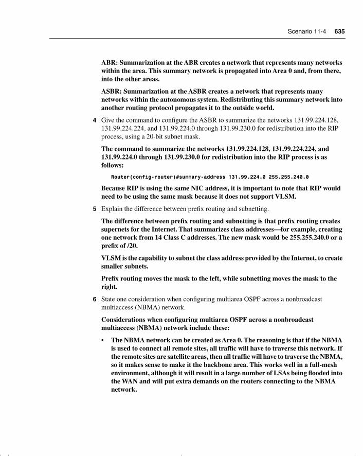
Scenario 11-4 635
ABR: Summarization at the ABR creates a network that represents many networks within the area. This summary network is propagated into Area 0 and, from there, into the other areas.
ASBR: Summarization at the ASBR creates a network that represents many networks within the autonomous system. Redistributing this summary network into another routing protocol propagates it to the outside world.
4 Give the command to configure the ASBR to summarize the networks 131.99.224.128, 131.99.224.224, and 131.99.224.0 through 131.99.230.0 for redistribution into the RIP process, using a 20-bit subnet mask.
The command to summarize the networks 131.99.224.128, 131.99.224.224, and 131.99.224.0 through 131.99.230.0 for redistribution into the RIP process is as follows:
Router(config-router)#summary-address 131.99.224.0 255.255.240.0
Because RIP is using the same NIC address, it is important to note that RIP would need to be using the same mask because it does not support VLSM.
5 Explain the difference between prefix routing and subnetting.
The difference between prefix routing and subnetting is that prefix routing creates supernets for the Internet. That summarizes class addresses—for example, creating one network from 14 Class C addresses. The new mask would be 255.255.240.0 or a prefix of /20.
VLSM is the capability to subnet the class address provided by the Internet, to create smaller subnets.
Prefix routing moves the mask to the left, while subnetting moves the mask to the right.
6 State one consideration when configuring multiarea OSPF across a nonbroadcast multiaccess (NBMA) network.
Considerations when configuring multiarea OSPF across a nonbroadcast multiaccess (NBMA) network include these:
• The NBMA network can be created as Area 0. The reasoning is that if the NBMA is used to connect all remote sites, all traffic will have to traverse this network. If the remote sites are satellite areas, then all traffic will have to traverse the NBMA, so it makes sense to make it the backbone area. This works well in a full-mesh environment, although it will result in a large number of LSAs being flooded into the WAN and will put extra demands on the routers connecting to the NBMA network.
chpt_01.book Page 635 Thursday, December 21, 2000 6:22 PM
636 Chapter 11: Scenarios for Final Preparation
• In a hub-and-spoke NBMA network it makes sense to assign the hub network as Area 0 with the other remote sites and the NBMA network as other areas. This is a good design if the satellite areas are stub areas because it means that the routing information, and thus network overhead, is kept to a minimum over the NBMA cloud. Depending on the design, the rest of the network may constitute one other area or multiple areas. This will depend on the size and growth expectations of the OSPF domain.
7 What command is used to turn on OSPF?
The command to turn on OSPF is as follows:
Router(config)# Router OSPF process-id
The process-id is subtly different from the autonomous system number used in IGRP and EIGRP. The process-id identifies the process. This allows more than one process to be configured on a router. Although unusual, there are instances in which this configuration is appropriate.
8 Explain why OSPF supports VLSM.
OSPF supports VLSM because it carries the subnet mask in the routing updates. Therefore, each router can reference the appropriate mask for each network.
9 Explain why all areas must connect through the backbone Area 0.
Area 0 forms a common path for all areas to connect. Therefore, it ensures that all areas are aware of all networks within the OSPF domain.
10 Explain the purpose of the network command in OSPF.
The network command is used to assign an interface or a group of interfaces to an area. When the interfaces are identified, they will participate in the OSPF routing process for the area to which they belong.
11 Which command is used to show a router’s internal OSPF routing table?
The command show ip ospf border-routers displays the internal routing table of the OSPF internal router.
12 Which command shows the use of VLSM on the OSPF network?
The show ip route command shows not only all the available routes, but also the masks used. If different masks are used, this command states that the subnet is variably subnetted, with the number of subnets and masks.
13 Which command verifies the establishment of adjacencies with other routers on the same network?
chpt_01.book Page 636 Thursday, December 21, 2000 6:22 PM
Scenario 11-4 637
The command show ip ospf neighbor shows the neighbors, the neighbor ID, the connecting interface address of the neighboring router, the outgoing interface on the router to connect to the neighbor, the length of time since the last communication from the neighbor, the connection state, and whether the neighbor is a designated router (DR) or backup designated router (BDR).
14 How would you see if there was more than one IP routing protocol running on a router? If more than one IP routing protocol was running on a router, how would you know how redistribution was configured?
There are a couple of ways to ascertain whether there was more than one routing protocol is running on a router. The first way is by issuing this command:
Router# show running
Because this command shows the configuration that is currently running, it is easy enough to see if more than one protocol is running and, if redistribution is running, how it is configured. The other and more straightforward method is to issue the following command:
Router# show ip protocols
This command shows all the IP protocols configured on the router, as well as the details of that configuration, including the redistribution.
15 When troubleshooting an OSPF configuration over an NBMA network, which command shows the network type that has been configured? It is understood that the command show running will display this information, but greater analysis of the timers and costs is required.
The command show ip ospf interface will indicate the network type, the delays set for the timers, and the number of neighbors and adjacencies.
16 Give the appropriate mask to use on a point-to-point serial interface, where IP unnumbered is not an option.
The mask to be used in a point-to-point link is 255.255.255.252. This mask allows the allocation of two addresses and is a typical mask for point-to-point networks.
17 What command would be used to identify that an adjacency could not be formed because one router was configured as a stub, while another was not?
The command debug IP ospf adjacency will show that there is a problem in the establishment in an adjacency. The error message would point to a mismatched stub/transit area option bit. You could also do a show ip ospf interface to see that the interface has no neighbors. At this point, it would be wise to check the interface configuration.
18 Which command is used to ensure that the virtual link is active?
The command show IP ospf virtual-links verifies the virtual link configuration.
chpt_01.book Page 637 Thursday, December 21, 2000 6:22 PM
638 Chapter 11: Scenarios for Final Preparation
19 What concern should you have when using the debug command?
The debug command is a command that should be used with caution because it can use an enormous amount of system resources. Given priority 1 as a process, it can eventually bring your router to a standstill. It is important to run the utility for a limited time to capture the required output. It is also best not to use the debug command from the console unless logging to the log file only. If the console screen freezes while using debug, there is no recovery other than to reboot the system.
20 What is a floating static route, and when would you use one?
A floating static route is used when a router has a link that is used as a backup using a medium such as a dialup line. The intention is to have no routing protocol running across the link that would keep the link active at a high cost.
The first task is to create a static route so that the routing protocol is not required. Unfortunately, the administrative distance that is used to select the best routes offered by different routing protocols states that a static route is the best route and will use it for all traffic. Thus, despite your best efforts, the backup link becomes a low-bandwidth, expensive primary link. To change the link to take backup status, manually configure the administrative distance to have a higher value than the dynamic routing protocol.
Scenario 11-5Part A of Scenario 11-5 begins with some planning guidelines that include planning the transition of the network to run EIGRP as the routing protocol. To transition smoothly, the intention is to slowly integrate EIGRP; this requires redistribution between EIGRP and OSPF as well as the filtering of updates between the protocols. After you complete Part A, Part B of the scenario asks you to configure the three routers to implement the planned design and a few other features. Finally, Part C asks you to examine router command output to discover details about the current operation. Part C also lists some questions related to the user interface and protocol specifications.
Scenario 11-5, Part A—PlanningYour job is to deploy a new network with three sites, as shown in Figure 11-7.
chpt_01.book Page 638 Thursday, December 21, 2000 6:22 PM
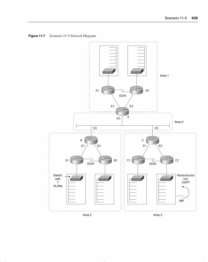
Scenario 11-5 639
Figure 11-7 Scenario 11-5 Network Diagram
B1
B
E0
E0
B2 C1
C
E0
C2
A
A1 A2
E1
E1
E2
E2 E1 E2
ISDN
ISDN ISDN
Area 1
Area 0
Area 3Area 2
Switchwith
7VLANs
Redistributedinto
OSPF
RIP
chpt_01.book Page 639 Thursday, December 21, 2000 6:22 PM
640 Chapter 11: Scenarios for Final Preparation
The OSPF network has limitations, and the decision has been made to change the routing protocol to EIGRP. Use the addressing scheme presented in the solutions of Scenario 11-4. For Part A of this scenario, perform the following tasks:
1 The planning committee has stated that the transition to EIGRP should start at the edges of the network and move inward in a controlled manner. Give a brief explanation of how you would implement a transition plan. Is summarization possible?
2 Redistribution is necessary. State the router(s) that would be responsible for redistribution and the nature of the redistribution.
3 To prevent routing loops, it has been decided to implement distribution filters. Plan the content, location, and implementation of the filters.
Solutions to Scenario 11-5, Part A—Planning Keeping the design as simple as possible, yet not making it so simple that the network cannot evolve, is a good practice. In these suggested answers, remember that many solutions are available. The reasoning behind this planning is to allow the optimum solution while maintaining the strength of the existing network. As in the Scenario 11-4 solution, the addressing scheme allows summarization at the core level of the network. The first few bits in the third octet indicate the summarization bits.
Many organizations decide to transition the network by starting at the outer peripheries of the network to minimize the impact of these changes. The problems that may occur when a change is made to an organization can be catastrophic. Inevitably, something is overlooked, or you have the dubious honor of discovering a new bug. Obviously, if the change is made to a stub network, the problem can be isolated and fixed speedily. Centralized routers with problems tend to share them with the rest of the network.
Alternative Methods of Transition to Another Routing ProtocolThe alternative methods of transition include no redistribution at all. For example:
• Each router could be visited in turn, OSPF could be turned off, and EIGRP could be turned on. The disadvantage of this approach is the time that it would take for the network to converge and the capability to troubleshoot any problems that might occur.
• Another solution, which is more practical, is to turn on EIGRP on all the routers and to run both protocols simultaneously. However, because EIGRP has a lower administrative distance than OSPF, routes from EIGRP would be added to the routing table before all the routers were configured. This would create black holes within the network.
chpt_01.book Page 640 Thursday, December 21, 2000 6:22 PM
Scenario 11-5 641
• The solution to this is to configure the administrative distance manually, making OSPF preferable to EIGRP. When all the routers have been configured and the network is stable, then it is easy enough to change all the routers to prefer EIGRP by changing the administrative distance back to the default. When the routers have converged, the OSPF protocol can be removed.
• A disadvantage of this solution is that the routers will require extra resources to run both protocols and, inevitably, there is a greater opportunity for black holes and routing loops.
Transitioning to EIGRP from the Outer Edges of the NetworkThe transition plan is very straightforward because the network in this scenario is very small. However, it reflects the strategy required by any size of network.
The implementation of EIGRP should start in Area 1. The reasoning for this is that there is currently no redistribution in the area, and it has an addressing scheme that is already set up for summarization.
Summarization in EIGRPSummarization is definitely possible, although EIGRP has no restrictions on summarization in the way OSPF only permits it at the ABR or ASBR. In EIGRP, summarization is configured at the interface level, which allows for great flexibility as well as confusion.
There are two ways to consider summarization in this network. The first is simply to implement the summarization put in place by OSPF. The addressing scheme supports it, and it makes good design sense. The other is necessary during the transition phase. This summarization occurs at the point of redistribution, to the external routes being passed into the new routing protocol.
Router A would be responsible for redistribution at the first level of transition—that would redistribute the routes from A1. If this transition went smoothly, then A2 would be configured for EIGRP. Then Area 2 could be changed to running EIGRP, one router at a time. The most complex redistribution would be in Area 3, which is already redistributing RIP into OSPF. Because RIP is here to stay in Building 2 of Area 3, care must be taken in the transition to EIGRP.
Building C1 would be an easy transition with redistribution on Router C. Router C2 would need to cut over to EIGRP and turn on redistribution immediately.
At this point, the only routers running OSPF are the core routers A, B, and C. The choice is now whether to transition one router at a time or to cut over in one fell swoop. Personally, I would cut over everything. If the transition is done at night, this is the safer method. Only three routers are involved, and the transition of the areas has now proven successful. There is a backup to restore everything to the status quo, in case problems are encountered.
chpt_01.book Page 641 Thursday, December 21, 2000 6:22 PM

642 Chapter 11: Scenarios for Final Preparation
Although this appears rather dangerous, it is much safer and cleaner than configuring further redistribution on the three core routers.
The routers must prevent feedback of routing information during redistribution. This can be done to avoid routing loops, which can result in the death of your network.
The purpose of the distribution lists is to prevent the routing processes telling each other what they already know. We will impose split horizons between the routing protocols manually.
Simply, when Router A is configured to redistribute the EIGRP routes from Router A1 into OSPF, OSPF will have a filter permitting only those routes to be redistributed. In this way, the routes that OSPF sends into EIGRP will not be propagated back into OSPF. Likewise, these filters will be set on routers B and C.
Scenario 11-5, Part B—ConfigurationThe next step in your job is to deploy the network designed in Scenario 11-5, Part A. Use the solutions for Part A of Scenario 11-5 to direct you in configuring the addressing and summarization at the Area Border Routers. For Scenario 11-5, Part B, perform the following tasks:
1 Configure basic EIGRP for routers A, B, and C based on Scenario 11-5, Part A’s design.
2 Configure summarization on routers A, B, and C.
3 Configure redistribution between OSPF and EIGRP on routers A, B, and C.
4 Configure distribution filters on routers A, B, and C.
Solutions to Scenario 11-5, Part B—Configuration Example 11-7, Example 11-8, and Example 11-9 show the configurations for Scenario 11-5, Part B, given the preceding criteria.
Example 11-7 Scenario 11-5 Router A Configuration
router eigrp 200network 131.99.0.0passive interface e0!!! This prevents updates from being sent out of interface!!! E0, which is in the OSPF domainredistribute ospf 100 metric 1000 100 1 255 1500!!! Previous configurationinterface e0ip address 131.99.0.49 255.255.255.240! 4 bits allows 14 hosts interface E1ip address 131.99.136.129 255.255.255.128! 7 bits allows 127 hostsip summary-address EIGRP 200 131.99.192.0 255.255.240.0
chpt_01.book Page 642 Thursday, December 21, 2000 6:22 PM
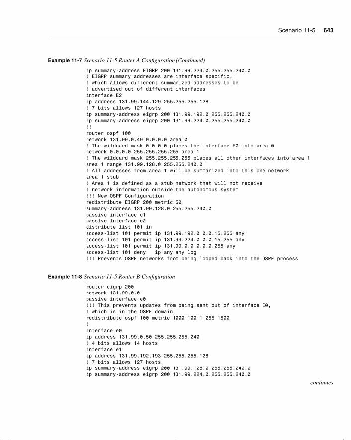
Scenario 11-5 643
ip summary-address EIGRP 200 131.99.224.0.255.255.240.0! EIGRP summary addresses are interface specific,! which allows different summarized addresses to be! advertised out of different interfacesinterface E2ip address 131.99.144.129 255.255.255.128! 7 bits allows 127 hostsip summary-address eigrp 200 131.99.192.0 255.255.240.0ip summary-address eigrp 200 131.99.224.0.255.255.240.0!!router ospf 100 network 131.99.0.49 0.0.0.0 area 0! The wildcard mask 0.0.0.0 places the interface E0 into area 0network 0.0.0.0 255.255.255.255 area 1! The wildcard mask 255.255.255.255 places all other interfaces into area 1area 1 range 131.99.128.0 255.255.240.0! All addresses from area 1 will be summarized into this one networkarea 1 stub! Area 1 is defined as a stub network that will not receive! network information outside the autonomous system!!! New OSPF Configurationredistribute EIGRP 200 metric 50summary-address 131.99.128.0 255.255.240.0passive interface e1passive interface e2distribute list 101 inaccess-list 101 permit ip 131.99.192.0 0.0.15.255 anyaccess-list 101 permit ip 131.99.224.0 0.0.15.255 anyaccess-list 101 permit ip 131.99.0.0 0.0.0.255 anyaccess-list 101 deny ip any any log!!! Prevents OSPF networks from being looped back into the OSPF process
Example 11-8 Scenario 11-5 Router B Configuration
router eigrp 200network 131.99.0.0passive interface e0!!! This prevents updates from being sent out of interface E0,! which is in the OSPF domainredistribute ospf 100 metric 1000 100 1 255 1500!interface e0ip address 131.99.0.50 255.255.255.240! 4 bits allows 14 hostsinterface e1ip address 131.99.192.193 255.255.255.128! 7 bits allows 127 hostsip summary-address eigrp 200 131.99.128.0 255.255.240.0ip summary-address eigrp 200 131.99.224.0.255.255.240.0
continues
Example 11-7 Scenario 11-5 Router A Configuration (Continued)
chpt_01.book Page 643 Thursday, December 21, 2000 6:22 PM
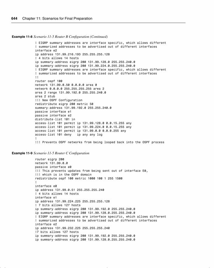
644 Chapter 11: Scenarios for Final Preparation
! EIGRP summary addresses are interface specific, which allows different! summarized addresses to be advertised out of different interfacesinterface e2ip address 131.99.216.193 255.255.255.128! 4 bits allows 14 hostsip summary-address eigrp 200 131.99.128.0 255.255.240.0ip summary-address eigrp 200 131.99.224.0.255.255.240.0! EIGRP summary addresses are interface specific, which allows different! summarized addresses to be advertised out of different interfaces!!router ospf 100 network 131.99.0.50 0.0.0.0 area 0network 0.0.0.0 255.255.255.255 area 2area 2 range 131.99.192.0 255.255.240.0area 2 stub!!! New OSPF Configurationredistribute eigrp 200 metric 50summary-address 131.99.192.0 255.255.240.0passive interface e1passive interface e2distribute-list 101 inaccess-list 101 permit ip 131.99.128.0 0.0.15.255 anyaccess-list 101 permit ip 131.99.224.0 0.0.15.255 anyaccess-list 101 permit ip 131.99.0.0 0.0.0.255 anyaccess-list 101 deny ip any any log!!!! Prevents OSPF networks from being looped back into the OSPF process
Example 11-9 Scenario 11-5 Router C Configuration
router eigrp 200network 131.99.0.0passive interface e0!!! This prevents updates from being sent out of interface E0,!!! which is in the OSPF domainredistribute ospf 100 metric 1000 100 1 255 1500!interface e0ip address 131.99.0.51 255.255.255.240! 4 bits allows 14 hostsinterface e1ip address 131.99.224.225 255.255.255.128! 7 bits allows 127 hostsip summary-address eigrp 200 131.99.192.0 255.255.240.0ip summary-address eigrp 200 131.99.128.0.255.255.240.0! EIGRP summary addresses are interface specific, which allows different! summarized addresses to be advertised out of different interfacesinterface e2ip address 131.99.232.225 255.255.255.240!7 bits allows 127 hostsip summary-address eigrp 200 131.99.192.0 255.255.240.0ip summary-address eigrp 200 131.99.128.0.255.255.240.0
Example 11-8 Scenario 11-5 Router B Configuration (Continued)
chpt_01.book Page 644 Thursday, December 21, 2000 6:22 PM
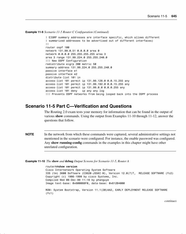
Scenario 11-5 645
Scenario 11-5 Part C—Verification and QuestionsThe Routing 2.0 exam tests your memory for information that can be found in the output of various show commands. Using the output from Examples 11-10 through 11-12, answer the questions that follow.
NOTE In the network from which these commands were captured, several administrative settings not mentioned in the scenario were configured. For instance, the enable password was configured. Any show running-config commands in the examples in this chapter might have other unrelated configuration.
! EIGRP summary addresses are interface specific, which allows different! summarized addresses to be advertised out of different interfaces)!!router ospf 100 network 131.99.0.51 0.0.0.0 area 0network 0.0.0.0 255.255.255.255 area 3area 3 range 131.99.224.0 255.255.240.0!!! New OSPF Configurationredistribute eigrp 200 metric 50summary-address 131.99.224.0 255.255.240.0passive interface e1passive interface e2distribute-list 101 inaccess-list 101 permit ip 131.99.128.0 0.0.15.255 anyaccess-list 101 permit ip 131.99.192.0 0.0.15.255 anyaccess-list 101 permit ip 131.99.0.0 0.0.0.255 anyaccess-list 101 deny ip any any log!!! Prevents OSPF networks from being looped back into the OSPF process
Example 11-10 The show and debug Output Screens for Scenario 11-5, Router A
routerA#show versionCisco Internetwork Operating System SoftwareIOS (tm) 3600 Software (C3620-JS56I-M), Version 12.0(7)T, RELEASE SOFTWARE (fc2)Copyright (c) 1986-1999 by cisco Systems, Inc.Compiled Wed 08-Dec-99 11:16 by phanguyeImage text-base: 0x600088F0, data-base: 0x612B4000 ROM: System Bootstrap, Version 11.1(20)AA2, EARLY DEPLOYMENT RELEASE SOFTWARE (fc1)
continues
Example 11-9 Scenario 11-5 Router C Configuration (Continued)
chpt_01.book Page 645 Thursday, December 21, 2000 6:22 PM
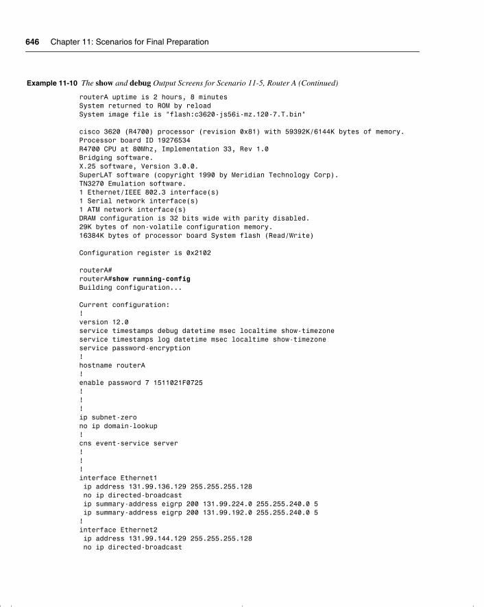
646 Chapter 11: Scenarios for Final Preparation
routerA uptime is 2 hours, 8 minutesSystem returned to ROM by reloadSystem image file is "flash:c3620-js56i-mz.120-7.T.bin" cisco 3620 (R4700) processor (revision 0x81) with 59392K/6144K bytes of memory.Processor board ID 19276534R4700 CPU at 80Mhz, Implementation 33, Rev 1.0Bridging software.X.25 software, Version 3.0.0.SuperLAT software (copyright 1990 by Meridian Technology Corp).TN3270 Emulation software.1 Ethernet/IEEE 802.3 interface(s)1 Serial network interface(s)1 ATM network interface(s)DRAM configuration is 32 bits wide with parity disabled.29K bytes of non-volatile configuration memory.16384K bytes of processor board System flash (Read/Write) Configuration register is 0x2102 routerA#routerA#show running-configBuilding configuration... Current configuration:!version 12.0service timestamps debug datetime msec localtime show-timezoneservice timestamps log datetime msec localtime show-timezoneservice password-encryption!hostname routerA!enable password 7 1511021F0725!!!ip subnet-zerono ip domain-lookup!cns event-service server!!!interface Ethernet1 ip address 131.99.136.129 255.255.255.128 no ip directed-broadcast ip summary-address eigrp 200 131.99.224.0 255.255.240.0 5 ip summary-address eigrp 200 131.99.192.0 255.255.240.0 5!interface Ethernet2 ip address 131.99.144.129 255.255.255.128 no ip directed-broadcast
Example 11-10 The show and debug Output Screens for Scenario 11-5, Router A (Continued)
chpt_01.book Page 646 Thursday, December 21, 2000 6:22 PM
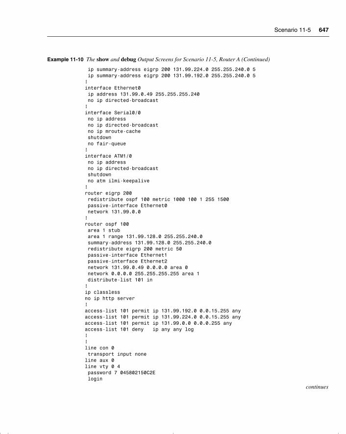
Scenario 11-5 647
ip summary-address eigrp 200 131.99.224.0 255.255.240.0 5 ip summary-address eigrp 200 131.99.192.0 255.255.240.0 5!interface Ethernet0 ip address 131.99.0.49 255.255.255.240 no ip directed-broadcast!interface Serial0/0 no ip address no ip directed-broadcast no ip mroute-cache shutdown no fair-queue!interface ATM1/0 no ip address no ip directed-broadcast shutdown no atm ilmi-keepalive!router eigrp 200 redistribute ospf 100 metric 1000 100 1 255 1500 passive-interface Ethernet0 network 131.99.0.0!router ospf 100 area 1 stub area 1 range 131.99.128.0 255.255.240.0 summary-address 131.99.128.0 255.255.240.0 redistribute eigrp 200 metric 50 passive-interface Ethernet1 passive-interface Ethernet2 network 131.99.0.49 0.0.0.0 area 0 network 0.0.0.0 255.255.255.255 area 1 distribute-list 101 in!ip classlessno ip http server!access-list 101 permit ip 131.99.192.0 0.0.15.255 anyaccess-list 101 permit ip 131.99.224.0 0.0.15.255 anyaccess-list 101 permit ip 131.99.0.0 0.0.0.255 anyaccess-list 101 deny ip any any log!!line con 0 transport input noneline aux 0line vty 0 4 password 7 045802150C2E login
continues
Example 11-10 The show and debug Output Screens for Scenario 11-5, Router A (Continued)
chpt_01.book Page 647 Thursday, December 21, 2000 6:22 PM

648 Chapter 11: Scenarios for Final Preparation
!end routerA#routerA#show ip interfaceEthernet0 is up, line protocol is up Internet address is 131.99.0.49/28 Broadcast address is 255.255.255.255 Address determined by non-volatile memory MTU is 1500 bytes Helper address is not set Directed broadcast forwarding is disabled Multicast reserved groups joined: 224.0.0.5 224.0.0.6 224.0.0.10 Outgoing access list is not set Inbound access list is not set Proxy ARP is enabled Security level is default Split horizon is enabled ICMP redirects are always sent ICMP unreachables are always sent ICMP mask replies are never sent IP fast switching is enabled IP fast switching on the same interface is disabled IP Flow switching is disabled IP Fast switching turbo vector IP multicast fast switching is enabled IP multicast distributed fast switching is disabled IP route-cache flags are Fast Router Discovery is disabled IP output packet accounting is disabled IP access violation accounting is disabled TCP/IP header compression is disabled RTP/IP header compression is disabled Probe proxy name replies are disabled Policy routing is disabled Network address translation is disabled WCCP Redirect outbound is disabled WCCP Redirect exclude is disabled BGP Policy Mapping is disabledSerial0/0 is administratively down, line protocol is down Internet protocol processing disabledATM1/0 is administratively down, line protocol is down Internet protocol processing disabledEthernet1 is up, line protocol is up Internet address is 131.99.136.129/25 Broadcast address is 255.255.255.255 Address determined by non-volatile memory MTU is 1514 bytes Helper address is not set Directed broadcast forwarding is disabled Multicast reserved groups joined: 224.0.0.5 224.0.0.6 224.0.0.10 Outgoing access list is not set Inbound access list is not set
Example 11-10 The show and debug Output Screens for Scenario 11-5, Router A (Continued)
chpt_01.book Page 648 Thursday, December 21, 2000 6:22 PM

Scenario 11-5 649
Proxy ARP is enabled Security level is default Split horizon is enabled ICMP redirects are always sent ICMP unreachables are always sent ICMP mask replies are never sent IP fast switching is disabled IP fast switching on the same interface is disabled IP Flow switching is disabled IP Fast switching turbo vector IP multicast fast switching is enabled IP multicast distributed fast switching is disabled IP route-cache flags are Fast Router Discovery is disabled IP output packet accounting is disabled IP access violation accounting is disabled TCP/IP header compression is disabled RTP/IP header compression is disabled Probe proxy name replies are disabled Policy routing is disabled Network address translation is disabled WCCP Redirect outbound is disabled WCCP Redirect exclude is disabled BGP Policy Mapping is disabledEthernet2 is up, line protocol is up Internet address is 131.99.144.129/25 Broadcast address is 255.255.255.255 Address determined by non-volatile memory MTU is 1514 bytes Helper address is not set Directed broadcast forwarding is disabled Multicast reserved groups joined: 224.0.0.5 224.0.0.6 224.0.0.10 Outgoing access list is not set Inbound access list is not set Proxy ARP is enabled Security level is default Split horizon is enabled ICMP redirects are always sent ICMP unreachables are always sent ICMP mask replies are never sent IP fast switching is disabled IP fast switching on the same interface is disabled IP Flow switching is disabled IP Fast switching turbo vector IP multicast fast switching is enabled IP multicast distributed fast switching is disabled IP route-cache flags are Fast Router Discovery is disabled IP output packet accounting is disabled IP access violation accounting is disabled TCP/IP header compression is disabled
continues
Example 11-10 The show and debug Output Screens for Scenario 11-5, Router A (Continued)
chpt_01.book Page 649 Thursday, December 21, 2000 6:22 PM
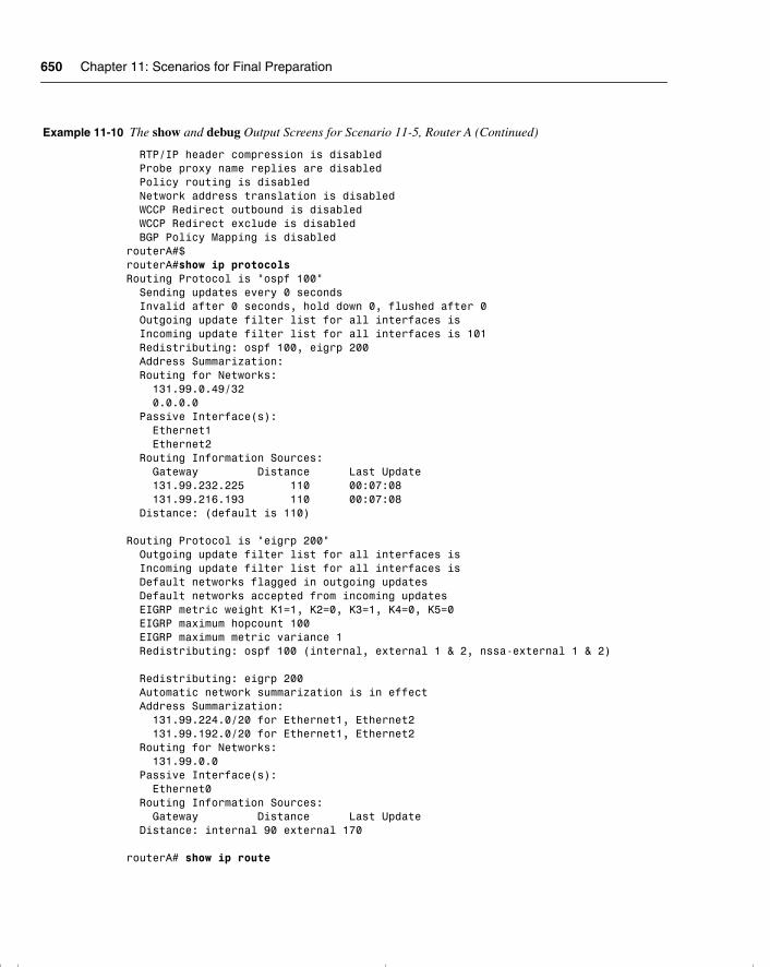
650 Chapter 11: Scenarios for Final Preparation
RTP/IP header compression is disabled Probe proxy name replies are disabled Policy routing is disabled Network address translation is disabled WCCP Redirect outbound is disabled WCCP Redirect exclude is disabled BGP Policy Mapping is disabledrouterA#$routerA#show ip protocolsRouting Protocol is "ospf 100" Sending updates every 0 seconds Invalid after 0 seconds, hold down 0, flushed after 0 Outgoing update filter list for all interfaces is Incoming update filter list for all interfaces is 101 Redistributing: ospf 100, eigrp 200 Address Summarization: Routing for Networks: 131.99.0.49/32 0.0.0.0 Passive Interface(s): Ethernet1 Ethernet2 Routing Information Sources: Gateway Distance Last Update 131.99.232.225 110 00:07:08 131.99.216.193 110 00:07:08 Distance: (default is 110) Routing Protocol is "eigrp 200" Outgoing update filter list for all interfaces is Incoming update filter list for all interfaces is Default networks flagged in outgoing updates Default networks accepted from incoming updates EIGRP metric weight K1=1, K2=0, K3=1, K4=0, K5=0 EIGRP maximum hopcount 100 EIGRP maximum metric variance 1 Redistributing: ospf 100 (internal, external 1 & 2, nssa-external 1 & 2) Redistributing: eigrp 200 Automatic network summarization is in effect Address Summarization: 131.99.224.0/20 for Ethernet1, Ethernet2 131.99.192.0/20 for Ethernet1, Ethernet2 Routing for Networks: 131.99.0.0 Passive Interface(s): Ethernet0 Routing Information Sources: Gateway Distance Last Update Distance: internal 90 external 170 routerA# show ip route
Example 11-10 The show and debug Output Screens for Scenario 11-5, Router A (Continued)
chpt_01.book Page 650 Thursday, December 21, 2000 6:22 PM
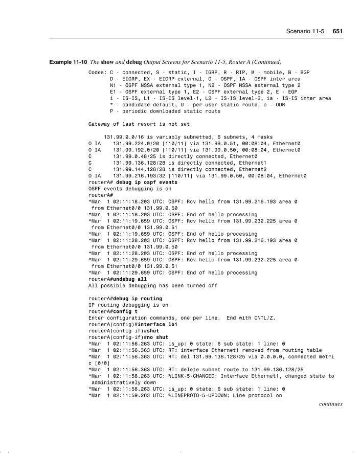
Scenario 11-5 651
Codes: C - connected, S - static, I - IGRP, R - RIP, M - mobile, B - BGP D - EIGRP, EX - EIGRP external, O - OSPF, IA - OSPF inter area N1 - OSPF NSSA external type 1, N2 - OSPF NSSA external type 2 E1 - OSPF external type 1, E2 - OSPF external type 2, E - EGP i - IS-IS, L1 - IS-IS level-1, L2 - IS-IS level-2, ia - IS-IS inter area * - candidate default, U - per-user static route, o - ODR P - periodic downloaded static route Gateway of last resort is not set 131.99.0.0/16 is variably subnetted, 6 subnets, 4 masksO IA 131.99.224.0/20 [110/11] via 131.99.0.51, 00:08:04, Ethernet0O IA 131.99.192.0/20 [110/11] via 131.99.0.50, 00:08:04, Ethernet0C 131.99.0.48/25 is directly connected, Ethernet0C 131.99.136.128/28 is directly connected, Ethernet1C 131.99.144.128/28 is directly connected, Ethernet2O IA 131.99.216.193/32 [110/11] via 131.99.0.50, 00:08:04, Ethernet0routerA# debug ip ospf eventsOSPF events debugging is onrouterA#*Mar 1 02:11:18.203 UTC: OSPF: Rcv hello from 131.99.216.193 area 0 from Ethernet0/0 131.99.0.50*Mar 1 02:11:18.203 UTC: OSPF: End of hello processing*Mar 1 02:11:19.659 UTC: OSPF: Rcv hello from 131.99.232.225 area 0 from Ethernet0/0 131.99.0.51*Mar 1 02:11:19.659 UTC: OSPF: End of hello processing*Mar 1 02:11:28.203 UTC: OSPF: Rcv hello from 131.99.216.193 area 0 from Ethernet0/0 131.99.0.50*Mar 1 02:11:28.203 UTC: OSPF: End of hello processing*Mar 1 02:11:29.659 UTC: OSPF: Rcv hello from 131.99.232.225 area 0 from Ethernet0/0 131.99.0.51*Mar 1 02:11:29.659 UTC: OSPF: End of hello processingrouterA#undebug allAll possible debugging has been turned off routerA#debug ip routingIP routing debugging is onrouterA#config tEnter configuration commands, one per line. End with CNTL/Z.routerA(config)#interface lo1routerA(config-if)#shutrouterA(config-if)#no shut*Mar 1 02:11:56.263 UTC: is_up: 0 state: 6 sub state: 1 line: 0*Mar 1 02:11:56.363 UTC: RT: interface Ethernet1 removed from routing table*Mar 1 02:11:56.363 UTC: RT: del 131.99.136.128/25 via 0.0.0.0, connected metric [0/0]*Mar 1 02:11:56.363 UTC: RT: delete subnet route to 131.99.136.128/25*Mar 1 02:11:58.263 UTC: %LINK-5-CHANGED: Interface Ethernet1, changed state to administratively down*Mar 1 02:11:58.263 UTC: is_up: 0 state: 6 sub state: 1 line: 0*Mar 1 02:11:59.263 UTC: %LINEPROTO-5-UPDOWN: Line protocol on
continues
Example 11-10 The show and debug Output Screens for Scenario 11-5, Router A (Continued)
chpt_01.book Page 651 Thursday, December 21, 2000 6:22 PM
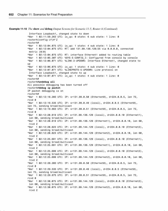
652 Chapter 11: Scenarios for Final Preparation
Interface Loopback1, changed state to down*Mar 1 02:11:59.263 UTC: is_up: 0 state: 6 sub state: 1 line: 0routerA(config-if)#^ZrouterA#*Mar 1 02:12:04.075 UTC: is_up: 1 state: 4 sub state: 1 line: 0*Mar 1 02:12:04.075 UTC: RT: add 131.99.136.128/25 via 0.0.0.0, connected metric [0/0]*Mar 1 02:12:04.075 UTC: RT: interface Ethernet1 added to routing table*Mar 1 02:12:05.307 UTC: %SYS-5-CONFIG_I: Configured from console by console*Mar 1 02:12:06.071 UTC: %LINK-3-UPDOWN: Interface Ethernet1, changed state toup*Mar 1 02:12:06.075 UTC: is_up: 1 state: 4 sub state: 1 line: 0*Mar 1 02:12:07.071 UTC: %LINEPROTO-5-UPDOWN: Line protocol on Interface Loopback1, changed state to up*Mar 1 02:12:07.071 UTC: is_up: 1 state: 4 sub state: 1 line: 0routerA#routerA#undebug allAll possible debugging has been turned offrouterA#debug ip packetIP packet debugging is onrouterA#*Mar 1 02:12:18.203 UTC: IP: s=131.99.0.50 (Ethernet0), d=224.0.0.5, len 72,rcvd 0*Mar 1 02:12:19.535 UTC: IP: s=131.99.0.49 (local), d=224.0.0.5 (Ethernet0),len 72, sending broad/multicast*Mar 1 02:12:19.663 UTC: IP: s=131.99.0.51 (Ethernet0), d=224.0.0.5, len 72,rcvd 0*Mar 1 02:12:20.819 UTC: IP: s=131.99.136.129 (local), d=224.0.0.10 (Ethernet1), len 60, sending broad/multicast*Mar 1 02:12:20.819 UTC: IP: s=131.99.136.129 (Ethernet1), d=224.0.0.10, len 60, rcvd 2*Mar 1 02:12:20.823 UTC: IP: s=131.99.144.129 (local), d=224.0.0.10 (Ethernet2), len 60, sending broad/multicast*Mar 1 02:12:20.823 UTC: IP: s=131.99.144.129 (Ethernet2), d=224.0.0.10, len 60, rcvd 2*Mar 1 02:12:25.691 UTC: IP: s=131.99.136.129 (local), d=224.0.0.10 (Ethernet1), len 60, sending broad/multicast*Mar 1 02:12:25.691 UTC: IP: s=131.99.136.129 (Ethernet1), d=224.0.0.10, len 60, rcvd 2*Mar 1 02:12:25.699 UTC: IP: s=131.99.144.129 (local), d=224.0.0.10 (Ethernet2), len 60, sending broad/multicast*Mar 1 02:12:25.699 UTC: IP: s=131.99.144.129 (Ethernet2), d=224.0.0.10, len 60, rcvd 2*Mar 1 02:12:28.203 UTC: IP: s=131.99.0.50 (Ethernet0), d=224.0.0.5, len 72,rcvd 0*Mar 1 02:12:29.535 UTC: IP: s=131.99.0.49 (local), d=224.0.0.5 (Ethernet0),len 72, sending broad/multicast*Mar 1 02:12:29.675 UTC: IP: s=131.99.0.51 (Ethernet0), d=224.0.0.5, len 72,rcvd 0*Mar 1 02:12:30.075 UTC: IP: s=131.99.144.129 (local), d=224.0.0.10 (Ethernet2), len 60, sending broad/multicast*Mar 1 02:12:30.075 UTC: IP: s=131.99.144.129 (Ethernet2), d=224.0.0.10, len 60, rcvd 2
Example 11-10 The show and debug Output Screens for Scenario 11-5, Router A (Continued)
chpt_01.book Page 652 Thursday, December 21, 2000 6:22 PM
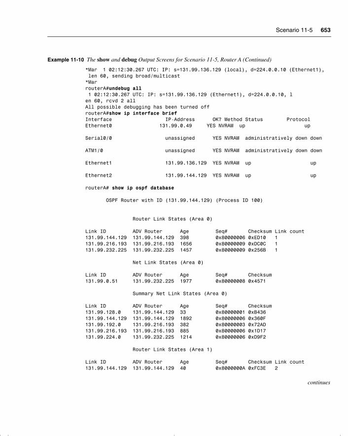
Scenario 11-5 653
*Mar 1 02:12:30.267 UTC: IP: s=131.99.136.129 (local), d=224.0.0.10 (Ethernet1), len 60, sending broad/multicast*MarrouterA#undebug all 1 02:12:30.267 UTC: IP: s=131.99.136.129 (Ethernet1), d=224.0.0.10, len 60, rcvd 2 allAll possible debugging has been turned offrouterA#show ip interface briefInterface IP-Address OK? Method Status ProtocolEthernet0 131.99.0.49 YES NVRAM up up Serial0/0 unassigned YES NVRAM administratively down down ATM1/0 unassigned YES NVRAM administratively down down Ethernet1 131.99.136.129 YES NVRAM up up Ethernet2 131.99.144.129 YES NVRAM up up routerA# show ip ospf database OSPF Router with ID (131.99.144.129) (Process ID 100) Router Link States (Area 0) Link ID ADV Router Age Seq# Checksum Link count131.99.144.129 131.99.144.129 398 0x80000006 0xED10 1131.99.216.193 131.99.216.193 1656 0x80000009 0xDC0C 1131.99.232.225 131.99.232.225 1457 0x80000009 0x256B 1 Net Link States (Area 0) Link ID ADV Router Age Seq# Checksum131.99.0.51 131.99.232.225 1977 0x80000008 0x4571 Summary Net Link States (Area 0) Link ID ADV Router Age Seq# Checksum131.99.128.0 131.99.144.129 33 0x80000001 0xB436131.99.144.129 131.99.144.129 1892 0x80000006 0x360F131.99.192.0 131.99.216.193 382 0x80000003 0x72AD131.99.216.193 131.99.216.193 885 0x80000006 0x1D17131.99.224.0 131.99.232.225 1214 0x80000006 0xD9F2 Router Link States (Area 1) Link ID ADV Router Age Seq# Checksum Link count131.99.144.129 131.99.144.129 40 0x8000000A 0xFC3E 2
continues
Example 11-10 The show and debug Output Screens for Scenario 11-5, Router A (Continued)
chpt_01.book Page 653 Thursday, December 21, 2000 6:22 PM
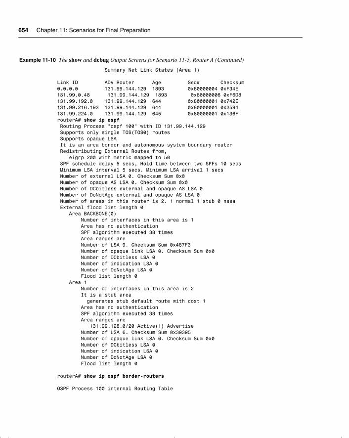
654 Chapter 11: Scenarios for Final Preparation
Summary Net Link States (Area 1) Link ID ADV Router Age Seq# Checksum0.0.0.0 131.99.144.129 1893 0x80000004 0xF34E131.99.0.48 131.99.144.129 1893 0x80000006 0xF6D8131.99.192.0 131.99.144.129 644 0x80000001 0x742E131.99.216.193 131.99.144.129 644 0x80000001 0x2594131.99.224.0 131.99.144.129 645 0x80000001 0x136FrouterA# show ip ospf Routing Process "ospf 100" with ID 131.99.144.129 Supports only single TOS(TOS0) routes Supports opaque LSA It is an area border and autonomous system boundary router Redistributing External Routes from, eigrp 200 with metric mapped to 50 SPF schedule delay 5 secs, Hold time between two SPFs 10 secs Minimum LSA interval 5 secs. Minimum LSA arrival 1 secs Number of external LSA 0. Checksum Sum 0x0 Number of opaque AS LSA 0. Checksum Sum 0x0 Number of DCbitless external and opaque AS LSA 0 Number of DoNotAge external and opaque AS LSA 0 Number of areas in this router is 2. 1 normal 1 stub 0 nssa External flood list length 0 Area BACKBONE(0) Number of interfaces in this area is 1 Area has no authentication SPF algorithm executed 38 times Area ranges are Number of LSA 9. Checksum Sum 0x487F3 Number of opaque link LSA 0. Checksum Sum 0x0 Number of DCbitless LSA 0 Number of indication LSA 0 Number of DoNotAge LSA 0 Flood list length 0 Area 1 Number of interfaces in this area is 2 It is a stub area generates stub default route with cost 1 Area has no authentication SPF algorithm executed 38 times Area ranges are 131.99.128.0/20 Active(1) Advertise Number of LSA 6. Checksum Sum 0x39395 Number of opaque link LSA 0. Checksum Sum 0x0 Number of DCbitless LSA 0 Number of indication LSA 0 Number of DoNotAge LSA 0 Flood list length 0 routerA# show ip ospf border-routers OSPF Process 100 internal Routing Table
Example 11-10 The show and debug Output Screens for Scenario 11-5, Router A (Continued)
chpt_01.book Page 654 Thursday, December 21, 2000 6:22 PM
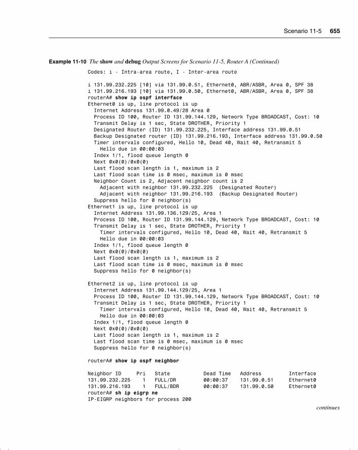
Scenario 11-5 655
Codes: i - Intra-area route, I - Inter-area route i 131.99.232.225 [10] via 131.99.0.51, Ethernet0, ABR/ASBR, Area 0, SPF 38i 131.99.216.193 [10] via 131.99.0.50, Ethernet0, ABR/ASBR, Area 0, SPF 38routerA# show ip ospf interfaceEthernet0 is up, line protocol is up Internet Address 131.99.0.49/28 Area 0 Process ID 100, Router ID 131.99.144.129, Network Type BROADCAST, Cost: 10 Transmit Delay is 1 sec, State DROTHER, Priority 1 Designated Router (ID) 131.99.232.225, Interface address 131.99.0.51 Backup Designated router (ID) 131.99.216.193, Interface address 131.99.0.50 Timer intervals configured, Hello 10, Dead 40, Wait 40, Retransmit 5 Hello due in 00:00:03 Index 1/1, flood queue length 0 Next 0x0(0)/0x0(0) Last flood scan length is 1, maximum is 2 Last flood scan time is 0 msec, maximum is 0 msec Neighbor Count is 2, Adjacent neighbor count is 2 Adjacent with neighbor 131.99.232.225 (Designated Router) Adjacent with neighbor 131.99.216.193 (Backup Designated Router) Suppress hello for 0 neighbor(s)Ethernet1 is up, line protocol is up Internet Address 131.99.136.129/25, Area 1 Process ID 100, Router ID 131.99.144.129, Network Type BROADCAST, Cost: 10 Transmit Delay is 1 sec, State DROTHER, Priority 1 Timer intervals configured, Hello 10, Dead 40, Wait 40, Retransmit 5 Hello due in 00:00:03 Index 1/1, flood queue length 0 Next 0x0(0)/0x0(0) Last flood scan length is 1, maximum is 2 Last flood scan time is 0 msec, maximum is 0 msec Suppress hello for 0 neighbor(s)
Ethernet2 is up, line protocol is up Internet Address 131.99.144.129/25, Area 1 Process ID 100, Router ID 131.99.144.129, Network Type BROADCAST, Cost: 10 Transmit Delay is 1 sec, State DROTHER, Priority 1 Timer intervals configured, Hello 10, Dead 40, Wait 40, Retransmit 5 Hello due in 00:00:03 Index 1/1, flood queue length 0 Next 0x0(0)/0x0(0) Last flood scan length is 1, maximum is 2 Last flood scan time is 0 msec, maximum is 0 msec Suppress hello for 0 neighbor(s)
routerA# show ip ospf neighbor Neighbor ID Pri State Dead Time Address Interface131.99.232.225 1 FULL/DR 00:00:37 131.99.0.51 Ethernet0131.99.216.193 1 FULL/BDR 00:00:37 131.99.0.50 Ethernet0routerA# sh ip eigrp neIP-EIGRP neighbors for process 200
continues
Example 11-10 The show and debug Output Screens for Scenario 11-5, Router A (Continued)
chpt_01.book Page 655 Thursday, December 21, 2000 6:22 PM
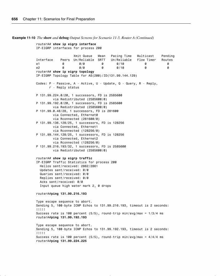
656 Chapter 11: Scenarios for Final Preparation
routerA# show ip eigrp interfaceIP-EIGRP interfaces for process 200 Xmit Queue Mean Pacing Time Multicast PendingInterface Peers Un/Reliable SRTT Un/Reliable Flow Timer Routese1 0 0/0 0 0/10 0 0e2 0 0/0 0 0/10 0 0routerA# show ip eigrp topologyIP-EIGRP Topology Table for AS(200)/ID(131.99.144.129) Codes: P - Passive, A - Active, U - Update, Q - Query, R - Reply, r - Reply status P 131.99.224.0/20, 1 successors, FD is 2585600 via Redistributed (2585600/0)P 131.99.192.0/20, 1 successors, FD is 2585600 via Redistributed (2585600/0)P 131.99.0.48/28, 1 successors, FD is 281600 via Connected, Ethernet0 via Rconnected (281600/0)P 131.99.136.128/25, 1 successors, FD is 128256 via Connected, Ethernet1 via Rconnected (128256/0)P 131.99.144.128/25, 1 successors, FD is 128256 via Connected, Ethernet2 via Rconnected (128256/0)P 131.99.216.193/32, 1 successors, FD is 2585600 via Redistributed (2585600/0)
routerA# show ip eigrp trafficIP-EIGRP Traffic Statistics for process 200 Hellos sent/received: 2862/2861 Updates sent/received: 0/0 Queries sent/received: 0/0 Replies sent/received: 0/0 Acks sent/received: 0/0 Input queue high water mark 2, 0 drops routerA#ping 131.99.216.193 Type escape sequence to abort.Sending 5, 100-byte ICMP Echos to 131.99.216.193, timeout is 2 seconds:!!!!!Success rate is 100 percent (5/5), round-trip min/avg/max = 1/3/4 msrouterA#ping 131.99.192.193 Type escape sequence to abort.Sending 5, 100-byte ICMP Echos to 131.99.192.193, timeout is 2 seconds:!!!!!Success rate is 100 percent (5/5), round-trip min/avg/max = 4/4/4 msrouterA#ping 131.99.224.225
Example 11-10 The show and debug Output Screens for Scenario 11-5, Router A (Continued)
chpt_01.book Page 656 Thursday, December 21, 2000 6:22 PM
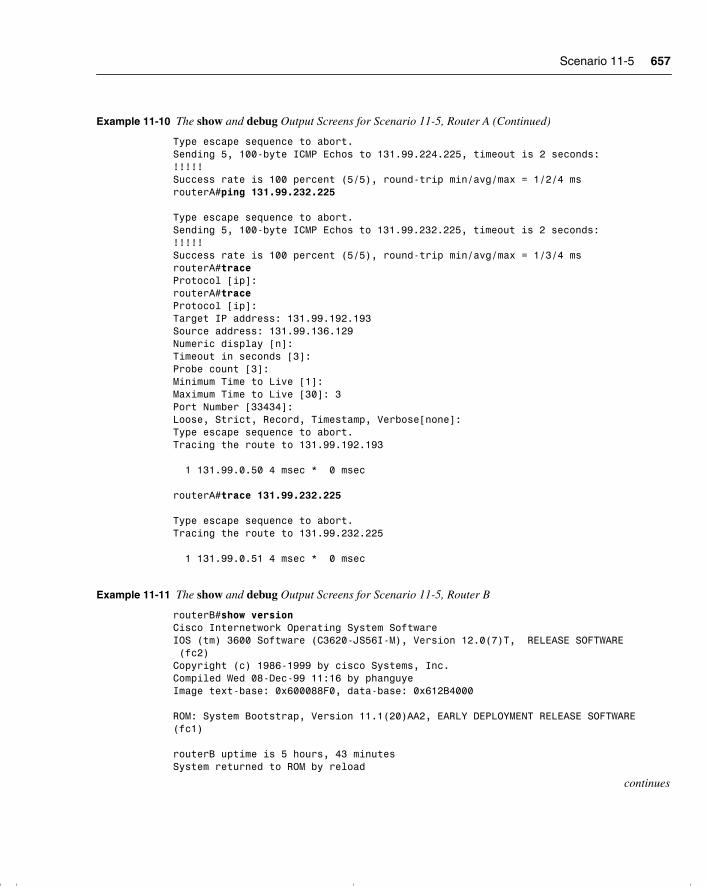
Scenario 11-5 657
Type escape sequence to abort.Sending 5, 100-byte ICMP Echos to 131.99.224.225, timeout is 2 seconds:!!!!!Success rate is 100 percent (5/5), round-trip min/avg/max = 1/2/4 msrouterA#ping 131.99.232.225 Type escape sequence to abort.Sending 5, 100-byte ICMP Echos to 131.99.232.225, timeout is 2 seconds:!!!!!Success rate is 100 percent (5/5), round-trip min/avg/max = 1/3/4 msrouterA#traceProtocol [ip]:routerA#traceProtocol [ip]:Target IP address: 131.99.192.193Source address: 131.99.136.129Numeric display [n]:Timeout in seconds [3]:Probe count [3]:Minimum Time to Live [1]:Maximum Time to Live [30]: 3Port Number [33434]:Loose, Strict, Record, Timestamp, Verbose[none]:Type escape sequence to abort.Tracing the route to 131.99.192.193 1 131.99.0.50 4 msec * 0 msec
routerA#trace 131.99.232.225 Type escape sequence to abort.Tracing the route to 131.99.232.225 1 131.99.0.51 4 msec * 0 msec
Example 11-11 The show and debug Output Screens for Scenario 11-5, Router B
routerB#show versionCisco Internetwork Operating System SoftwareIOS (tm) 3600 Software (C3620-JS56I-M), Version 12.0(7)T, RELEASE SOFTWARE (fc2)Copyright (c) 1986-1999 by cisco Systems, Inc.Compiled Wed 08-Dec-99 11:16 by phanguyeImage text-base: 0x600088F0, data-base: 0x612B4000 ROM: System Bootstrap, Version 11.1(20)AA2, EARLY DEPLOYMENT RELEASE SOFTWARE (fc1) routerB uptime is 5 hours, 43 minutesSystem returned to ROM by reload
continues
Example 11-10 The show and debug Output Screens for Scenario 11-5, Router A (Continued)
chpt_01.book Page 657 Thursday, December 21, 2000 6:22 PM
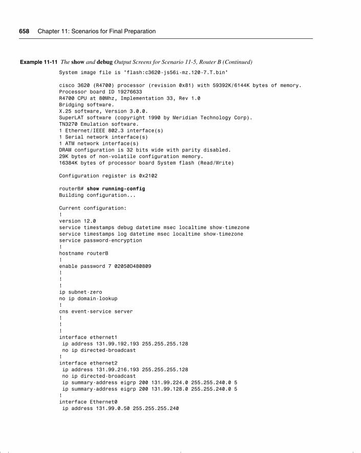
658 Chapter 11: Scenarios for Final Preparation
System image file is "flash:c3620-js56i-mz.120-7.T.bin" cisco 3620 (R4700) processor (revision 0x81) with 59392K/6144K bytes of memory.Processor board ID 19276633R4700 CPU at 80Mhz, Implementation 33, Rev 1.0Bridging software.X.25 software, Version 3.0.0.SuperLAT software (copyright 1990 by Meridian Technology Corp).TN3270 Emulation software.1 Ethernet/IEEE 802.3 interface(s)1 Serial network interface(s)1 ATM network interface(s)DRAM configuration is 32 bits wide with parity disabled.29K bytes of non-volatile configuration memory.16384K bytes of processor board System flash (Read/Write) Configuration register is 0x2102 routerB# show running-configBuilding configuration... Current configuration:!version 12.0service timestamps debug datetime msec localtime show-timezoneservice timestamps log datetime msec localtime show-timezoneservice password-encryption!hostname routerB!enable password 7 02050D480809!!!ip subnet-zerono ip domain-lookup!cns event-service server!!!interface ethernet1 ip address 131.99.192.193 255.255.255.128 no ip directed-broadcast!interface ethernet2 ip address 131.99.216.193 255.255.255.128 no ip directed-broadcast ip summary-address eigrp 200 131.99.224.0 255.255.240.0 5 ip summary-address eigrp 200 131.99.128.0 255.255.240.0 5!interface Ethernet0 ip address 131.99.0.50 255.255.255.240
Example 11-11 The show and debug Output Screens for Scenario 11-5, Router B (Continued)
chpt_01.book Page 658 Thursday, December 21, 2000 6:22 PM
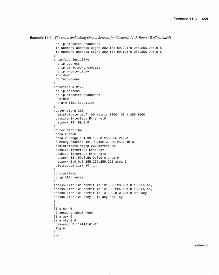
Scenario 11-5 659
no ip directed-broadcast ip summary-address eigrp 200 131.99.224.0 255.255.240.0 5 ip summary-address eigrp 200 131.99.128.0 255.255.240.0 5!interface Serial0/0 no ip address no ip directed-broadcast no ip mroute-cache shutdown no fair-queue!interface ATM1/0 no ip address no ip directed-broadcast shutdown no atm ilmi-keepalive!router eigrp 200 redistribute ospf 100 metric 1000 100 1 255 1500 passive-interface Ethernet0 network 131.99.0.0!router ospf 100 area 2 stub area 2 range 131.99.192.0 255.255.240.0 summary-address 131.99.192.0 255.255.240.0 redistribute eigrp 200 metric 50 passive-interface Ethernet1 passive-interface Ethernet2 network 131.99.0.50 0.0.0.0 area 0 network 0.0.0.0 255.255.255.255 area 2 distribute-list 101 in!ip classlessno ip http server!access-list 101 permit ip 131.99.128.0 0.0.15.255 anyaccess-list 101 permit ip 131.99.224.0 0.0.15.255 anyaccess-list 101 permit ip 131.99.0.0 0.0.0.255 anyaccess-list 101 deny ip any any log!!line con 0 transport input noneline aux 0line vty 0 4 password 7 110A1016141D login!end
continues
Example 11-11 The show and debug Output Screens for Scenario 11-5, Router B (Continued)
chpt_01.book Page 659 Thursday, December 21, 2000 6:22 PM
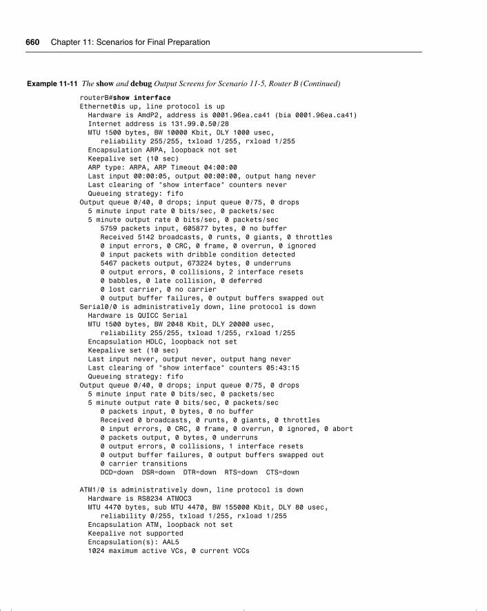
660 Chapter 11: Scenarios for Final Preparation
routerB#show interfaceEthernet0is up, line protocol is up Hardware is AmdP2, address is 0001.96ea.ca41 (bia 0001.96ea.ca41) Internet address is 131.99.0.50/28 MTU 1500 bytes, BW 10000 Kbit, DLY 1000 usec, reliability 255/255, txload 1/255, rxload 1/255 Encapsulation ARPA, loopback not set Keepalive set (10 sec) ARP type: ARPA, ARP Timeout 04:00:00 Last input 00:00:05, output 00:00:00, output hang never Last clearing of "show interface" counters never Queueing strategy: fifoOutput queue 0/40, 0 drops; input queue 0/75, 0 drops 5 minute input rate 0 bits/sec, 0 packets/sec 5 minute output rate 0 bits/sec, 0 packets/sec 5759 packets input, 605877 bytes, 0 no buffer Received 5142 broadcasts, 0 runts, 0 giants, 0 throttles 0 input errors, 0 CRC, 0 frame, 0 overrun, 0 ignored 0 input packets with dribble condition detected 5467 packets output, 673224 bytes, 0 underruns 0 output errors, 0 collisions, 2 interface resets 0 babbles, 0 late collision, 0 deferred 0 lost carrier, 0 no carrier 0 output buffer failures, 0 output buffers swapped outSerial0/0 is administratively down, line protocol is down Hardware is QUICC Serial MTU 1500 bytes, BW 2048 Kbit, DLY 20000 usec, reliability 255/255, txload 1/255, rxload 1/255 Encapsulation HDLC, loopback not set Keepalive set (10 sec) Last input never, output never, output hang never Last clearing of "show interface" counters 05:43:15 Queueing strategy: fifoOutput queue 0/40, 0 drops; input queue 0/75, 0 drops 5 minute input rate 0 bits/sec, 0 packets/sec 5 minute output rate 0 bits/sec, 0 packets/sec 0 packets input, 0 bytes, 0 no buffer Received 0 broadcasts, 0 runts, 0 giants, 0 throttles 0 input errors, 0 CRC, 0 frame, 0 overrun, 0 ignored, 0 abort 0 packets output, 0 bytes, 0 underruns 0 output errors, 0 collisions, 1 interface resets 0 output buffer failures, 0 output buffers swapped out 0 carrier transitions DCD=down DSR=down DTR=down RTS=down CTS=down ATM1/0 is administratively down, line protocol is down Hardware is RS8234 ATMOC3 MTU 4470 bytes, sub MTU 4470, BW 155000 Kbit, DLY 80 usec, reliability 0/255, txload 1/255, rxload 1/255 Encapsulation ATM, loopback not set Keepalive not supported Encapsulation(s): AAL5 1024 maximum active VCs, 0 current VCCs
Example 11-11 The show and debug Output Screens for Scenario 11-5, Router B (Continued)
chpt_01.book Page 660 Thursday, December 21, 2000 6:22 PM
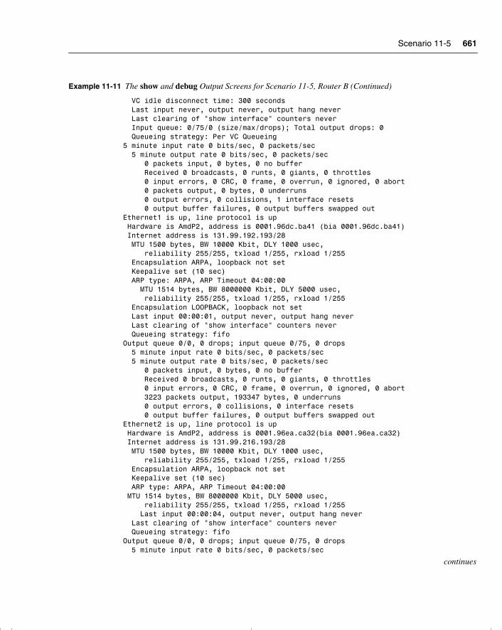
Scenario 11-5 661
VC idle disconnect time: 300 seconds Last input never, output never, output hang never Last clearing of "show interface" counters never Input queue: 0/75/0 (size/max/drops); Total output drops: 0 Queueing strategy: Per VC Queueing5 minute input rate 0 bits/sec, 0 packets/sec 5 minute output rate 0 bits/sec, 0 packets/sec 0 packets input, 0 bytes, 0 no buffer Received 0 broadcasts, 0 runts, 0 giants, 0 throttles 0 input errors, 0 CRC, 0 frame, 0 overrun, 0 ignored, 0 abort 0 packets output, 0 bytes, 0 underruns 0 output errors, 0 collisions, 1 interface resets 0 output buffer failures, 0 output buffers swapped outEthernet1 is up, line protocol is up Hardware is AmdP2, address is 0001.96dc.ba41 (bia 0001.96dc.ba41) Internet address is 131.99.192.193/28 MTU 1500 bytes, BW 10000 Kbit, DLY 1000 usec, reliability 255/255, txload 1/255, rxload 1/255 Encapsulation ARPA, loopback not set Keepalive set (10 sec) ARP type: ARPA, ARP Timeout 04:00:00 MTU 1514 bytes, BW 8000000 Kbit, DLY 5000 usec, reliability 255/255, txload 1/255, rxload 1/255 Encapsulation LOOPBACK, loopback not set Last input 00:00:01, output never, output hang never Last clearing of "show interface" counters never Queueing strategy: fifoOutput queue 0/0, 0 drops; input queue 0/75, 0 drops 5 minute input rate 0 bits/sec, 0 packets/sec 5 minute output rate 0 bits/sec, 0 packets/sec 0 packets input, 0 bytes, 0 no buffer Received 0 broadcasts, 0 runts, 0 giants, 0 throttles 0 input errors, 0 CRC, 0 frame, 0 overrun, 0 ignored, 0 abort 3223 packets output, 193347 bytes, 0 underruns 0 output errors, 0 collisions, 0 interface resets 0 output buffer failures, 0 output buffers swapped outEthernet2 is up, line protocol is up Hardware is AmdP2, address is 0001.96ea.ca32(bia 0001.96ea.ca32) Internet address is 131.99.216.193/28 MTU 1500 bytes, BW 10000 Kbit, DLY 1000 usec, reliability 255/255, txload 1/255, rxload 1/255 Encapsulation ARPA, loopback not set Keepalive set (10 sec) ARP type: ARPA, ARP Timeout 04:00:00 MTU 1514 bytes, BW 8000000 Kbit, DLY 5000 usec, reliability 255/255, txload 1/255, rxload 1/255 Last input 00:00:04, output never, output hang never Last clearing of "show interface" counters never Queueing strategy: fifoOutput queue 0/0, 0 drops; input queue 0/75, 0 drops 5 minute input rate 0 bits/sec, 0 packets/sec
continues
Example 11-11 The show and debug Output Screens for Scenario 11-5, Router B (Continued)
chpt_01.book Page 661 Thursday, December 21, 2000 6:22 PM
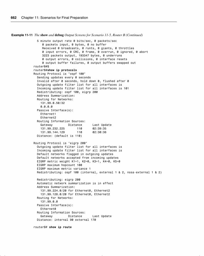
662 Chapter 11: Scenarios for Final Preparation
5 minute output rate 0 bits/sec, 0 packets/sec 0 packets input, 0 bytes, 0 no buffer Received 0 broadcasts, 0 runts, 0 giants, 0 throttles 0 input errors, 0 CRC, 0 frame, 0 overrun, 0 ignored, 0 abort 3223 packets output, 193347 bytes, 0 underruns 0 output errors, 0 collisions, 0 interface resets 0 output buffer failures, 0 output buffers swapped outrouterB#$routerB#show ip protocolsRouting Protocol is "ospf 100" Sending updates every 0 seconds Invalid after 0 seconds, hold down 0, flushed after 0 Outgoing update filter list for all interfaces is Incoming update filter list for all interfaces is 101 Redistributing: ospf 100, eigrp 200 Address Summarization: Routing for Networks: 131.99.0.50/32 0.0.0.0 Passive Interface(s): Ethernet1 Ethernet2 Routing Information Sources: Gateway Distance Last Update 131.99.232.225 110 02:39:35 131.99.144.129 110 02:30:36 Distance: (default is 110) Routing Protocol is "eigrp 200" Outgoing update filter list for all interfaces is Incoming update filter list for all interfaces is Default networks flagged in outgoing updates Default networks accepted from incoming updates EIGRP metric weight K1=1, K2=0, K3=1, K4=0, K5=0 EIGRP maximum hopcount 100 EIGRP maximum metric variance 1 Redistributing: ospf 100 (internal, external 1 & 2, nssa-external 1 & 2) Redistributing: eigrp 200 Automatic network summarization is in effect Address Summarization: 131.99.224.0/20 for Ethernet0, Ethernet2 131.99.128.0/20 for Ethernet0, Ethernet2 Routing for Networks: 131.99.0.0 Passive Interface(s): Ethernet0 Routing Information Sources: Gateway Distance Last Update Distance: internal 90 external 170 routerB# show ip route
Example 11-11 The show and debug Output Screens for Scenario 11-5, Router B (Continued)
chpt_01.book Page 662 Thursday, December 21, 2000 6:22 PM
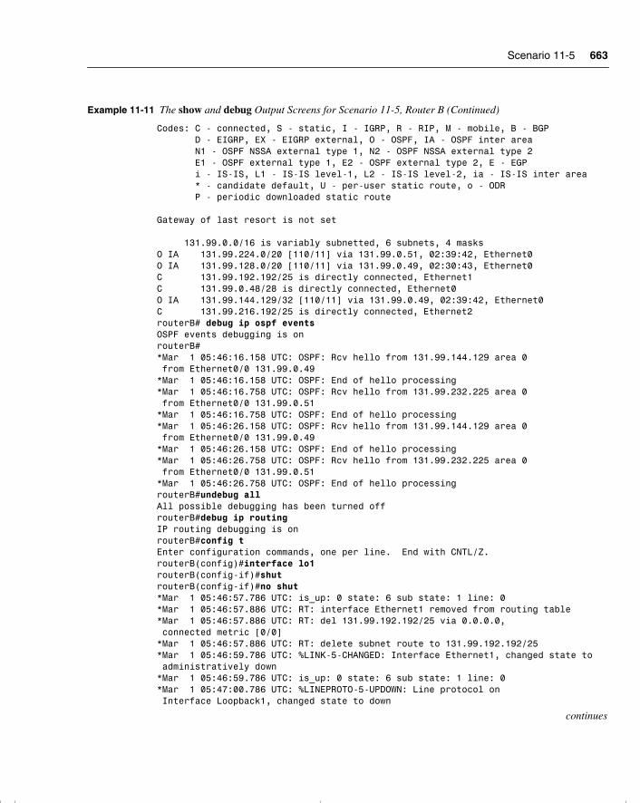
Scenario 11-5 663
Codes: C - connected, S - static, I - IGRP, R - RIP, M - mobile, B - BGP D - EIGRP, EX - EIGRP external, O - OSPF, IA - OSPF inter area N1 - OSPF NSSA external type 1, N2 - OSPF NSSA external type 2 E1 - OSPF external type 1, E2 - OSPF external type 2, E - EGP i - IS-IS, L1 - IS-IS level-1, L2 - IS-IS level-2, ia - IS-IS inter area * - candidate default, U - per-user static route, o - ODR P - periodic downloaded static route Gateway of last resort is not set 131.99.0.0/16 is variably subnetted, 6 subnets, 4 masksO IA 131.99.224.0/20 [110/11] via 131.99.0.51, 02:39:42, Ethernet0O IA 131.99.128.0/20 [110/11] via 131.99.0.49, 02:30:43, Ethernet0C 131.99.192.192/25 is directly connected, Ethernet1C 131.99.0.48/28 is directly connected, Ethernet0O IA 131.99.144.129/32 [110/11] via 131.99.0.49, 02:39:42, Ethernet0C 131.99.216.192/25 is directly connected, Ethernet2routerB# debug ip ospf eventsOSPF events debugging is onrouterB#*Mar 1 05:46:16.158 UTC: OSPF: Rcv hello from 131.99.144.129 area 0 from Ethernet0/0 131.99.0.49*Mar 1 05:46:16.158 UTC: OSPF: End of hello processing*Mar 1 05:46:16.758 UTC: OSPF: Rcv hello from 131.99.232.225 area 0 from Ethernet0/0 131.99.0.51*Mar 1 05:46:16.758 UTC: OSPF: End of hello processing*Mar 1 05:46:26.158 UTC: OSPF: Rcv hello from 131.99.144.129 area 0 from Ethernet0/0 131.99.0.49*Mar 1 05:46:26.158 UTC: OSPF: End of hello processing*Mar 1 05:46:26.758 UTC: OSPF: Rcv hello from 131.99.232.225 area 0 from Ethernet0/0 131.99.0.51*Mar 1 05:46:26.758 UTC: OSPF: End of hello processingrouterB#undebug allAll possible debugging has been turned offrouterB#debug ip routingIP routing debugging is onrouterB#config tEnter configuration commands, one per line. End with CNTL/Z.routerB(config)#interface lo1routerB(config-if)#shutrouterB(config-if)#no shut*Mar 1 05:46:57.786 UTC: is_up: 0 state: 6 sub state: 1 line: 0*Mar 1 05:46:57.886 UTC: RT: interface Ethernet1 removed from routing table*Mar 1 05:46:57.886 UTC: RT: del 131.99.192.192/25 via 0.0.0.0, connected metric [0/0]*Mar 1 05:46:57.886 UTC: RT: delete subnet route to 131.99.192.192/25*Mar 1 05:46:59.786 UTC: %LINK-5-CHANGED: Interface Ethernet1, changed state to administratively down*Mar 1 05:46:59.786 UTC: is_up: 0 state: 6 sub state: 1 line: 0*Mar 1 05:47:00.786 UTC: %LINEPROTO-5-UPDOWN: Line protocol on Interface Loopback1, changed state to down
continues
Example 11-11 The show and debug Output Screens for Scenario 11-5, Router B (Continued)
chpt_01.book Page 663 Thursday, December 21, 2000 6:22 PM
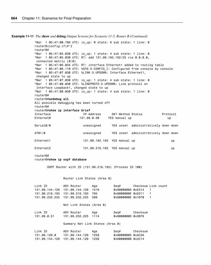
664 Chapter 11: Scenarios for Final Preparation
*Mar 1 05:47:00.786 UTC: is_up: 0 state: 6 sub state: 1 line: 0routerB(config-if)#^ZrouterB#*Mar 1 05:47:05.030 UTC: is_up: 1 state: 4 sub state: 1 line: 0*Mar 1 05:47:05.030 UTC: RT: add 131.99.192.192/25 via 0.0.0.0, connected metric [0/0]*Mar 1 05:47:05.034 UTC: RT: interface Ethernet1 added to routing table*Mar 1 05:47:06.110 UTC: %SYS-5-CONFIG_I: Configured from console by console*Mar 1 05:47:07.030 UTC: %LINK-3-UPDOWN: Interface Ethernet1, changed state to up*Mar 1 05:47:07.030 UTC: is_up: 1 state: 4 sub state: 1 line: 0*Mar 1 05:47:08.030 UTC: %LINEPROTO-5-UPDOWN: Line protocol on Interface Loopback1, changed state to up*Mar 1 05:47:08.030 UTC: is_up: 1 state: 4 sub state: 1 line: 0routerB#routerB#undebug allAll possible debugging has been turned offrouterB#routerB#show ip interface briefInterface IP-Address OK? Method Status ProtocolEthernet0 131.99.0.50 YES manual up up Serial0/0 unassigned YES unset administratively down down ATM1/0 unassigned YES unset administratively down down Ethernet1 131.99.192.193 YES manual up up Ethernet2 131.99.216.193 YES manual up up routerB#routerB#show ip ospf database OSPF Router with ID (131.99.216.193) (Process ID 100) Router Link States (Area 0) Link ID ADV Router Age Seq# Checksum Link count131.99.144.129 131.99.144.129 1516 0x8000000A 0xE514 1131.99.216.193 131.99.216.193 765 0x8000000E 0xD211 1131.99.232.225 131.99.232.225 599 0x8000000E 0x1B70 1 Net Link States (Area 0) Link ID ADV Router Age Seq# Checksum131.99.0.51 131.99.232.225 1114 0x8000000D 0x3B76 Summary Net Link States (Area 0) Link ID ADV Router Age Seq# Checksum131.99.128.0 131.99.144.129 1258 0x80000005 0xAC3A131.99.144.129 131.99.144.129 1258 0x8000000B 0x2C14
Example 11-11 The show and debug Output Screens for Scenario 11-5, Router B (Continued)
chpt_01.book Page 664 Thursday, December 21, 2000 6:22 PM
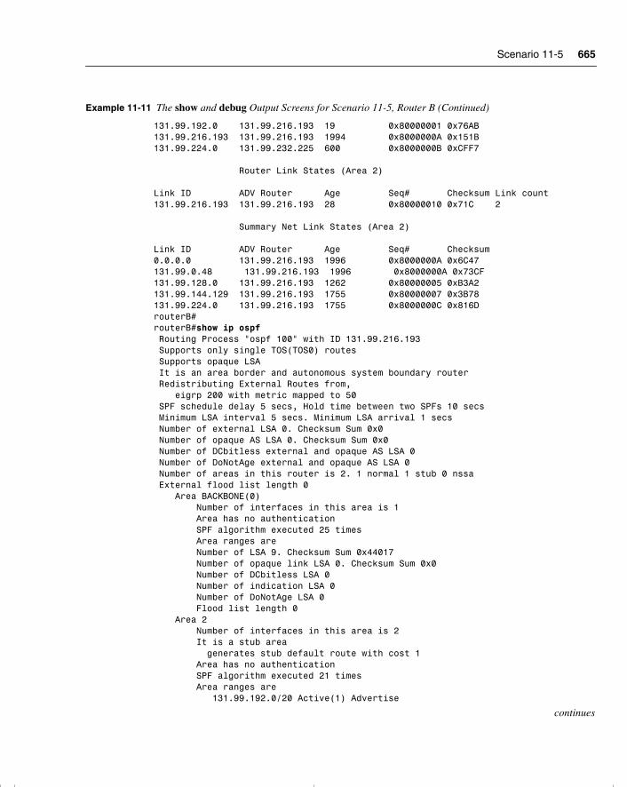
Scenario 11-5 665
131.99.192.0 131.99.216.193 19 0x80000001 0x76AB131.99.216.193 131.99.216.193 1994 0x8000000A 0x151B131.99.224.0 131.99.232.225 600 0x8000000B 0xCFF7 Router Link States (Area 2) Link ID ADV Router Age Seq# Checksum Link count131.99.216.193 131.99.216.193 28 0x80000010 0x71C 2 Summary Net Link States (Area 2) Link ID ADV Router Age Seq# Checksum0.0.0.0 131.99.216.193 1996 0x8000000A 0x6C47131.99.0.48 131.99.216.193 1996 0x8000000A 0x73CF131.99.128.0 131.99.216.193 1262 0x80000005 0xB3A2131.99.144.129 131.99.216.193 1755 0x80000007 0x3B78131.99.224.0 131.99.216.193 1755 0x8000000C 0x816DrouterB#routerB#show ip ospf Routing Process "ospf 100" with ID 131.99.216.193 Supports only single TOS(TOS0) routes Supports opaque LSA It is an area border and autonomous system boundary router Redistributing External Routes from, eigrp 200 with metric mapped to 50 SPF schedule delay 5 secs, Hold time between two SPFs 10 secs Minimum LSA interval 5 secs. Minimum LSA arrival 1 secs Number of external LSA 0. Checksum Sum 0x0 Number of opaque AS LSA 0. Checksum Sum 0x0 Number of DCbitless external and opaque AS LSA 0 Number of DoNotAge external and opaque AS LSA 0 Number of areas in this router is 2. 1 normal 1 stub 0 nssa External flood list length 0 Area BACKBONE(0) Number of interfaces in this area is 1 Area has no authentication SPF algorithm executed 25 times Area ranges are Number of LSA 9. Checksum Sum 0x44017 Number of opaque link LSA 0. Checksum Sum 0x0 Number of DCbitless LSA 0 Number of indication LSA 0 Number of DoNotAge LSA 0 Flood list length 0 Area 2 Number of interfaces in this area is 2 It is a stub area generates stub default route with cost 1 Area has no authentication SPF algorithm executed 21 times Area ranges are 131.99.192.0/20 Active(1) Advertise
continues
Example 11-11 The show and debug Output Screens for Scenario 11-5, Router B (Continued)
chpt_01.book Page 665 Thursday, December 21, 2000 6:22 PM
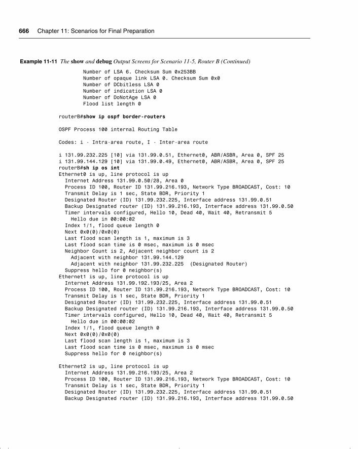
666 Chapter 11: Scenarios for Final Preparation
Number of LSA 6. Checksum Sum 0x253BB Number of opaque link LSA 0. Checksum Sum 0x0 Number of DCbitless LSA 0 Number of indication LSA 0 Number of DoNotAge LSA 0 Flood list length 0 routerB#show ip ospf border-routers OSPF Process 100 internal Routing Table Codes: i - Intra-area route, I - Inter-area route i 131.99.232.225 [10] via 131.99.0.51, Ethernet0, ABR/ASBR, Area 0, SPF 25i 131.99.144.129 [10] via 131.99.0.49, Ethernet0, ABR/ASBR, Area 0, SPF 25routerB#sh ip os intEthernet0 is up, line protocol is up Internet Address 131.99.0.50/28, Area 0 Process ID 100, Router ID 131.99.216.193, Network Type BROADCAST, Cost: 10 Transmit Delay is 1 sec, State BDR, Priority 1 Designated Router (ID) 131.99.232.225, Interface address 131.99.0.51 Backup Designated router (ID) 131.99.216.193, Interface address 131.99.0.50 Timer intervals configured, Hello 10, Dead 40, Wait 40, Retransmit 5 Hello due in 00:00:02 Index 1/1, flood queue length 0 Next 0x0(0)/0x0(0) Last flood scan length is 1, maximum is 3 Last flood scan time is 0 msec, maximum is 0 msec Neighbor Count is 2, Adjacent neighbor count is 2 Adjacent with neighbor 131.99.144.129 Adjacent with neighbor 131.99.232.225 (Designated Router) Suppress hello for 0 neighbor(s)Ethernet1 is up, line protocol is up Internet Address 131.99.192.193/25, Area 2 Process ID 100, Router ID 131.99.216.193, Network Type BROADCAST, Cost: 10 Transmit Delay is 1 sec, State BDR, Priority 1 Designated Router (ID) 131.99.232.225, Interface address 131.99.0.51 Backup Designated router (ID) 131.99.216.193, Interface address 131.99.0.50 Timer intervals configured, Hello 10, Dead 40, Wait 40, Retransmit 5 Hello due in 00:00:02 Index 1/1, flood queue length 0 Next 0x0(0)/0x0(0) Last flood scan length is 1, maximum is 3 Last flood scan time is 0 msec, maximum is 0 msec Suppress hello for 0 neighbor(s)
Ethernet2 is up, line protocol is up Internet Address 131.99.216.193/25, Area 2 Process ID 100, Router ID 131.99.216.193, Network Type BROADCAST, Cost: 10 Transmit Delay is 1 sec, State BDR, Priority 1 Designated Router (ID) 131.99.232.225, Interface address 131.99.0.51 Backup Designated router (ID) 131.99.216.193, Interface address 131.99.0.50
Example 11-11 The show and debug Output Screens for Scenario 11-5, Router B (Continued)
chpt_01.book Page 666 Thursday, December 21, 2000 6:22 PM
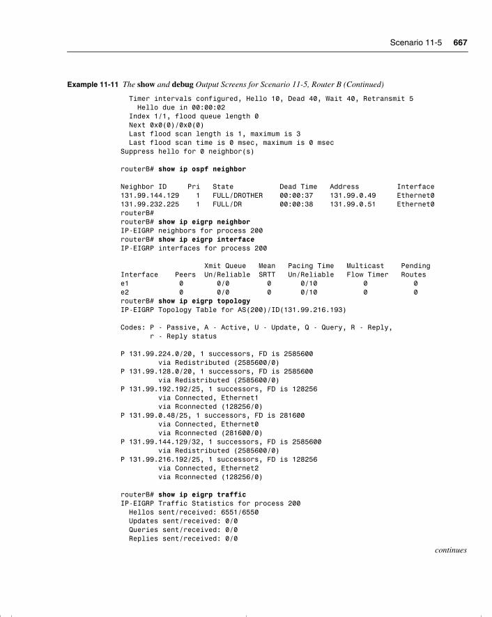
Scenario 11-5 667
Timer intervals configured, Hello 10, Dead 40, Wait 40, Retransmit 5 Hello due in 00:00:02 Index 1/1, flood queue length 0 Next 0x0(0)/0x0(0) Last flood scan length is 1, maximum is 3 Last flood scan time is 0 msec, maximum is 0 msecSuppress hello for 0 neighbor(s)
routerB# show ip ospf neighbor Neighbor ID Pri State Dead Time Address Interface131.99.144.129 1 FULL/DROTHER 00:00:37 131.99.0.49 Ethernet0131.99.232.225 1 FULL/DR 00:00:38 131.99.0.51 Ethernet0routerB#routerB# show ip eigrp neighborIP-EIGRP neighbors for process 200routerB# show ip eigrp interfaceIP-EIGRP interfaces for process 200 Xmit Queue Mean Pacing Time Multicast PendingInterface Peers Un/Reliable SRTT Un/Reliable Flow Timer Routese1 0 0/0 0 0/10 0 0e2 0 0/0 0 0/10 0 0routerB# show ip eigrp topologyIP-EIGRP Topology Table for AS(200)/ID(131.99.216.193) Codes: P - Passive, A - Active, U - Update, Q - Query, R - Reply, r - Reply status P 131.99.224.0/20, 1 successors, FD is 2585600 via Redistributed (2585600/0)P 131.99.128.0/20, 1 successors, FD is 2585600 via Redistributed (2585600/0)P 131.99.192.192/25, 1 successors, FD is 128256 via Connected, Ethernet1 via Rconnected (128256/0)P 131.99.0.48/25, 1 successors, FD is 281600 via Connected, Ethernet0 via Rconnected (281600/0)P 131.99.144.129/32, 1 successors, FD is 2585600 via Redistributed (2585600/0)P 131.99.216.192/25, 1 successors, FD is 128256 via Connected, Ethernet2 via Rconnected (128256/0)
routerB# show ip eigrp trafficIP-EIGRP Traffic Statistics for process 200 Hellos sent/received: 6551/6550 Updates sent/received: 0/0 Queries sent/received: 0/0 Replies sent/received: 0/0
continues
Example 11-11 The show and debug Output Screens for Scenario 11-5, Router B (Continued)
chpt_01.book Page 667 Thursday, December 21, 2000 6:22 PM
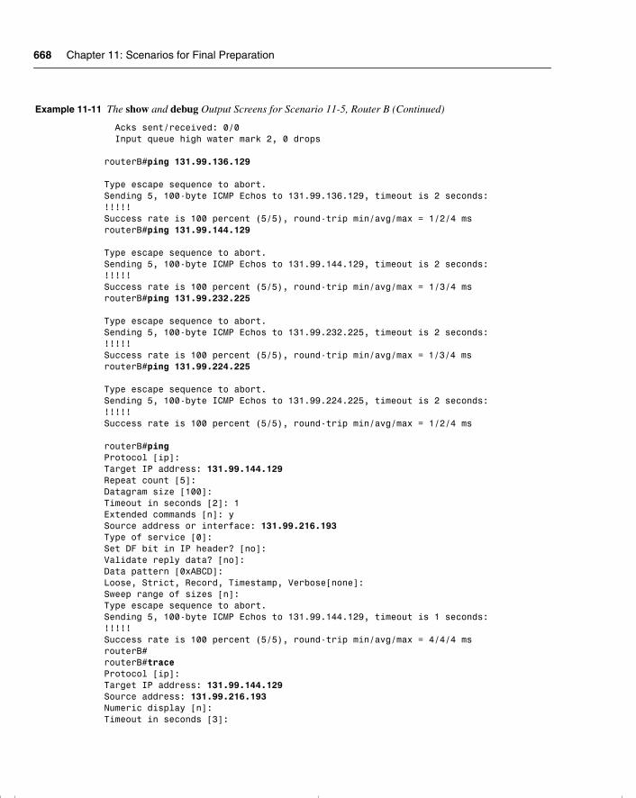
668 Chapter 11: Scenarios for Final Preparation
Acks sent/received: 0/0 Input queue high water mark 2, 0 drops routerB#ping 131.99.136.129 Type escape sequence to abort.Sending 5, 100-byte ICMP Echos to 131.99.136.129, timeout is 2 seconds:!!!!!Success rate is 100 percent (5/5), round-trip min/avg/max = 1/2/4 msrouterB#ping 131.99.144.129 Type escape sequence to abort.Sending 5, 100-byte ICMP Echos to 131.99.144.129, timeout is 2 seconds:!!!!!Success rate is 100 percent (5/5), round-trip min/avg/max = 1/3/4 msrouterB#ping 131.99.232.225 Type escape sequence to abort.Sending 5, 100-byte ICMP Echos to 131.99.232.225, timeout is 2 seconds:!!!!!Success rate is 100 percent (5/5), round-trip min/avg/max = 1/3/4 msrouterB#ping 131.99.224.225 Type escape sequence to abort.Sending 5, 100-byte ICMP Echos to 131.99.224.225, timeout is 2 seconds:!!!!!Success rate is 100 percent (5/5), round-trip min/avg/max = 1/2/4 ms
routerB#pingProtocol [ip]:Target IP address: 131.99.144.129Repeat count [5]:Datagram size [100]:Timeout in seconds [2]: 1Extended commands [n]: ySource address or interface: 131.99.216.193Type of service [0]:Set DF bit in IP header? [no]:Validate reply data? [no]:Data pattern [0xABCD]:Loose, Strict, Record, Timestamp, Verbose[none]:Sweep range of sizes [n]:Type escape sequence to abort.Sending 5, 100-byte ICMP Echos to 131.99.144.129, timeout is 1 seconds:!!!!!Success rate is 100 percent (5/5), round-trip min/avg/max = 4/4/4 msrouterB#routerB#traceProtocol [ip]:Target IP address: 131.99.144.129Source address: 131.99.216.193Numeric display [n]:Timeout in seconds [3]:
Example 11-11 The show and debug Output Screens for Scenario 11-5, Router B (Continued)
chpt_01.book Page 668 Thursday, December 21, 2000 6:22 PM
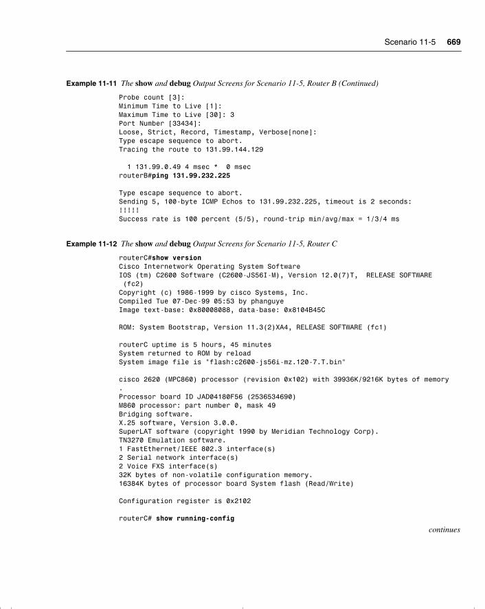
Scenario 11-5 669
Probe count [3]:Minimum Time to Live [1]:Maximum Time to Live [30]: 3Port Number [33434]:Loose, Strict, Record, Timestamp, Verbose[none]:Type escape sequence to abort.Tracing the route to 131.99.144.129 1 131.99.0.49 4 msec * 0 msecrouterB#ping 131.99.232.225 Type escape sequence to abort.Sending 5, 100-byte ICMP Echos to 131.99.232.225, timeout is 2 seconds:!!!!!Success rate is 100 percent (5/5), round-trip min/avg/max = 1/3/4 ms
Example 11-12 The show and debug Output Screens for Scenario 11-5, Router C
routerC#show versionCisco Internetwork Operating System SoftwareIOS (tm) C2600 Software (C2600-JS56I-M), Version 12.0(7)T, RELEASE SOFTWARE (fc2)Copyright (c) 1986-1999 by cisco Systems, Inc.Compiled Tue 07-Dec-99 05:53 by phanguyeImage text-base: 0x80008088, data-base: 0x8104B45C ROM: System Bootstrap, Version 11.3(2)XA4, RELEASE SOFTWARE (fc1) routerC uptime is 5 hours, 45 minutesSystem returned to ROM by reloadSystem image file is "flash:c2600-js56i-mz.120-7.T.bin" cisco 2620 (MPC860) processor (revision 0x102) with 39936K/9216K bytes of memory.Processor board ID JAD04180F56 (2536534690)M860 processor: part number 0, mask 49Bridging software.X.25 software, Version 3.0.0.SuperLAT software (copyright 1990 by Meridian Technology Corp).TN3270 Emulation software.1 FastEthernet/IEEE 802.3 interface(s)2 Serial network interface(s)2 Voice FXS interface(s)32K bytes of non-volatile configuration memory.16384K bytes of processor board System flash (Read/Write) Configuration register is 0x2102 routerC# show running-config
continues
Example 11-11 The show and debug Output Screens for Scenario 11-5, Router B (Continued)
chpt_01.book Page 669 Thursday, December 21, 2000 6:22 PM
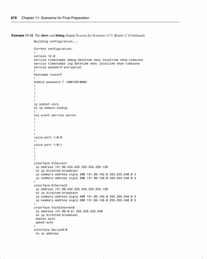
670 Chapter 11: Scenarios for Final Preparation
Building configuration... Current configuration:!version 12.0service timestamps debug datetime msec localtime show-timezoneservice timestamps log datetime msec localtime show-timezoneservice password-encryption!hostname routerC!enable password 7 13061E010803!!!!!ip subnet-zerono ip domain-lookup!cns event-service server!!!!!voice-port 1/0/0!voice-port 1/0/1!!!!interface Ethernet1 ip address 131.99.224.225 255.255.255.128 no ip directed-broadcast ip summary-address eigrp 200 131.99.192.0 255.255.240.0 5 ip summary-address eigrp 200 131.99.128.0 255.255.240.0 5!interface Ethernet2 ip address 131.99.232.225 255.255.255.128 no ip directed-broadcast ip summary-address eigrp 200 131.99.192.0 255.255.240.0 5 ip summary-address eigrp 200 131.99.128.0 255.255.240.0 5!interface FastEthernet0 ip address 131.99.0.51 255.255.255.240 no ip directed-broadcast duplex auto speed auto!interface Serial0/0 no ip address
Example 11-12 The show and debug Output Screens for Scenario 11-5, Router C (Continued)
chpt_01.book Page 670 Thursday, December 21, 2000 6:22 PM
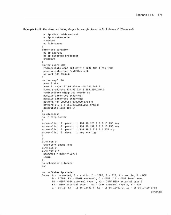
Scenario 11-5 671
no ip directed-broadcast no ip mroute-cache shutdown no fair-queue!interface Serial0/1 no ip address no ip directed-broadcast shutdown!router eigrp 200 redistribute ospf 100 metric 1000 100 1 255 1500 passive-interface FastEthernet0 network 131.99.0.0!router ospf 100 area 3 stub area 3 range 131.99.224.0 255.255.240.0 summary-address 131.99.224.0 255.255.240.0 redistribute eigrp 200 metric 50 passive-interface Ethernet1 passive-interface Ethernet2 network 131.99.0.51 0.0.0.0 area 0 network 0.0.0.0 255.255.255.255 area 3 distribute-list 101 in!ip classlessno ip http server!access-list 101 permit ip 131.99.128.0 0.0.15.255 anyaccess-list 101 permit ip 131.99.192.0 0.0.15.255 anyaccess-list 101 permit ip 131.99.0.0 0.0.0.255 anyaccess-list 101 deny ip any any log!!line con 0 transport input noneline aux 0line vty 0 4 password 7 00071A150754 login!no scheduler allocateend routerC#show ip routeCodes: C - connected, S - static, I - IGRP, R - RIP, M - mobile, B - BGP D - EIGRP, EX - EIGRP external, O - OSPF, IA - OSPF inter area N1 - OSPF NSSA external type 1, N2 - OSPF NSSA external type 2 E1 - OSPF external type 1, E2 - OSPF external type 2, E - EGP i - IS-IS, L1 - IS-IS level-1, L2 - IS-IS level-2, ia - IS-IS inter area
continues
Example 11-12 The show and debug Output Screens for Scenario 11-5, Router C (Continued)
chpt_01.book Page 671 Thursday, December 21, 2000 6:22 PM
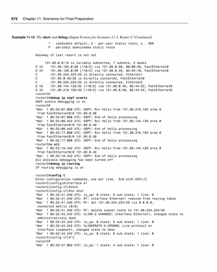
672 Chapter 11: Scenarios for Final Preparation
* - candidate default, U - per-user static route, o - ODR P - periodic downloaded static route Gateway of last resort is not set 131.99.0.0/16 is variably subnetted, 7 subnets, 4 masksO IA 131.99.192.0/20 [110/2] via 131.99.0.50, 00:00:56, FastEthernet0O IA 131.99.128.0/20 [110/2] via 131.99.0.49, 02:34:10, FastEthernet0C 131.99.224.224/25 is directly connected, Ethernet1C 131.99.0.48/28 is directly connected, FastEthernet0C 131.99.232.224/25 is directly connected, Ethernet2O IA 131.99.144.129/32 [110/2] via 131.99.0.49, 02:44:52, FastEthernet0O IA 131.99.216.193/32 [110/2] via 131.99.0.50, 02:44:52, FastEthernet0routerC#routerC#debug ip ospf eventsOSPF events debugging is onrouterC#*Mar 1 05:52:07.090 UTC: OSPF: Rcv hello from 131.99.216.193 area 0 from FastEthernet0/0 131.99.0.50*Mar 1 05:52:07.090 UTC: OSPF: End of hello processing*Mar 1 05:52:08.442 UTC: OSPF: Rcv hello from 131.99.144.129 area 0 from FastEthernet0/0 131.99.0.49*Mar 1 05:52:08.442 UTC: OSPF: End of hello processing*Mar 1 05:52:17.090 UTC: OSPF: Rcv hello from 131.99.216.193 area 0 from FastEthernet0/0 131.99.0.50*Mar 1 05:52:17.090 UTC: OSPF: End of hello processingrouterC#u all*Mar 1 05:52:18.442 UTC: OSPF: Rcv hello from 131.99.144.129 area 0 from FastEthernet0/0 131.99.0.49*Mar 1 05:52:18.442 UTC: OSPF: End of hello processingAll possible debugging has been turned offrouterC#debug ip routingIP routing debugging is on
routerC#config tEnter configuration commands, one per line. End with CNTL/Z.routerC(config)#interface e1routerC(config-if)#shutrouterC(config-if)#no shut*Mar 1 05:52:41.246 UTC: is_up: 0 state: 6 sub state: 1 line: 0*Mar 1 05:52:41.346 UTC: RT: interface Ethernet1 removed from routing table*Mar 1 05:52:41.346 UTC: RT: del 131.99.224.224/28 via 0.0.0.0, connected metric [0/0]*Mar 1 05:52:41.346 UTC: RT: delete subnet route to 131.99.224.224/28*Mar 1 05:52:43.242 UTC: %LINK-5-CHANGED: Interface Ethernet1, changed state to administratively down*Mar 1 05:52:43.242 UTC: is_up: 0 state: 6 sub state: 1 line: 0*Mar 1 05:52:44.242 UTC: %LINEPROTO-5-UPDOWN: Line protocol on Interface Loopback1, changed state to down*Mar 1 05:52:44.242 UTC: is_up: 0 state: 6 sub state: 1 line: 0routerC(config-if)#^ZrouterC#*Mar 1 05:52:47.062 UTC: is_up: 1 state: 4 sub state: 1 line: 0
Example 11-12 The show and debug Output Screens for Scenario 11-5, Router C (Continued)
chpt_01.book Page 672 Thursday, December 21, 2000 6:22 PM
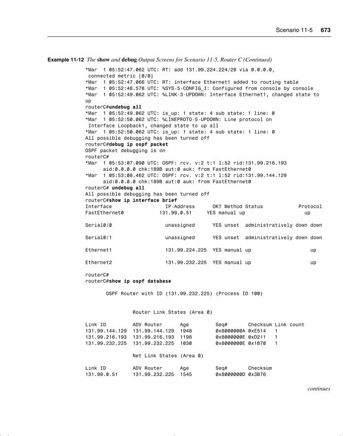
Scenario 11-5 673
*Mar 1 05:52:47.062 UTC: RT: add 131.99.224.224/28 via 0.0.0.0, connected metric [0/0]*Mar 1 05:52:47.066 UTC: RT: interface Ethernet1 added to routing table*Mar 1 05:52:48.578 UTC: %SYS-5-CONFIG_I: Configured from console by console*Mar 1 05:52:49.062 UTC: %LINK-3-UPDOWN: Interface Ethernet1, changed state touprouterC#undebug all*Mar 1 05:52:49.062 UTC: is_up: 1 state: 4 sub state: 1 line: 0*Mar 1 05:52:50.062 UTC: %LINEPROTO-5-UPDOWN: Line protocol on Interface Loopback1, changed state to up all*Mar 1 05:52:50.062 UTC: is_up: 1 state: 4 sub state: 1 line: 0All possible debugging has been turned offrouterC#debug ip ospf packetOSPF packet debugging is onrouterC#*Mar 1 05:53:07.090 UTC: OSPF: rcv. v:2 t:1 l:52 rid:131.99.216.193 aid:0.0.0.0 chk:189B aut:0 auk: from FastEthernet0*Mar 1 05:53:08.462 UTC: OSPF: rcv. v:2 t:1 l:52 rid:131.99.144.129 aid:0.0.0.0 chk:189B aut:0 auk: from FastEthernet0routerC# undebug allAll possible debugging has been turned offrouterC#show ip interface briefInterface IP-Address OK? Method Status ProtocolFastEthernet0 131.99.0.51 YES manual up up Serial0/0 unassigned YES unset administratively down down Serial0/1 unassigned YES unset administratively down down Ethernet1 131.99.224.225 YES manual up up Ethernet2 131.99.232.225 YES manual up up routerC#routerC#show ip ospf database OSPF Router with ID (131.99.232.225) (Process ID 100) Router Link States (Area 0) Link ID ADV Router Age Seq# Checksum Link count131.99.144.129 131.99.144.129 1948 0x8000000A 0xE514 1131.99.216.193 131.99.216.193 1198 0x8000000E 0xD211 1131.99.232.225 131.99.232.225 1030 0x8000000E 0x1B70 1 Net Link States (Area 0) Link ID ADV Router Age Seq# Checksum131.99.0.51 131.99.232.225 1545 0x8000000D 0x3B76
continues
Example 11-12 The show and debug Output Screens for Scenario 11-5, Router C (Continued)
chpt_01.book Page 673 Thursday, December 21, 2000 6:22 PM
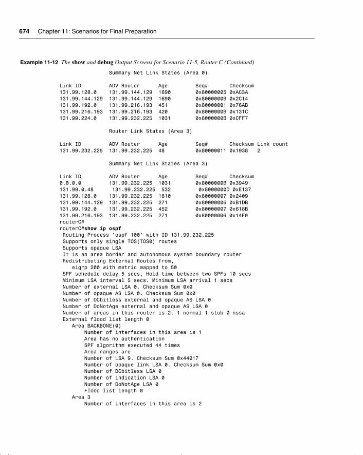
674 Chapter 11: Scenarios for Final Preparation
Summary Net Link States (Area 0) Link ID ADV Router Age Seq# Checksum131.99.128.0 131.99.144.129 1690 0x80000005 0xAC3A131.99.144.129 131.99.144.129 1690 0x8000000B 0x2C14131.99.192.0 131.99.216.193 451 0x80000001 0x76AB131.99.216.193 131.99.216.193 420 0x8000000B 0x131C131.99.224.0 131.99.232.225 1031 0x8000000B 0xCFF7 Router Link States (Area 3) Link ID ADV Router Age Seq# Checksum Link count131.99.232.225 131.99.232.225 48 0x80000011 0x1938 2 Summary Net Link States (Area 3) Link ID ADV Router Age Seq# Checksum0.0.0.0 131.99.232.225 1031 0x8000000B 0x3949131.99.0.48 131.99.232.225 532 0x8000000D 0xE137131.99.128.0 131.99.232.225 1810 0x80000007 0x2409131.99.144.129 131.99.232.225 271 0x80000006 0xB1DB131.99.192.0 131.99.232.225 452 0x80000007 0x618B131.99.216.193 131.99.232.225 271 0x80000006 0x14F0routerC#routerC#show ip ospf Routing Process "ospf 100" with ID 131.99.232.225 Supports only single TOS(TOS0) routes Supports opaque LSA It is an area border and autonomous system boundary router Redistributing External Routes from, eigrp 200 with metric mapped to 50 SPF schedule delay 5 secs, Hold time between two SPFs 10 secs Minimum LSA interval 5 secs. Minimum LSA arrival 1 secs Number of external LSA 0. Checksum Sum 0x0 Number of opaque AS LSA 0. Checksum Sum 0x0 Number of DCbitless external and opaque AS LSA 0 Number of DoNotAge external and opaque AS LSA 0 Number of areas in this router is 2. 1 normal 1 stub 0 nssa External flood list length 0 Area BACKBONE(0) Number of interfaces in this area is 1 Area has no authentication SPF algorithm executed 44 times Area ranges are Number of LSA 9. Checksum Sum 0x44017 Number of opaque link LSA 0. Checksum Sum 0x0 Number of DCbitless LSA 0 Number of indication LSA 0 Number of DoNotAge LSA 0 Flood list length 0 Area 3 Number of interfaces in this area is 2
Example 11-12 The show and debug Output Screens for Scenario 11-5, Router C (Continued)
chpt_01.book Page 674 Thursday, December 21, 2000 6:22 PM
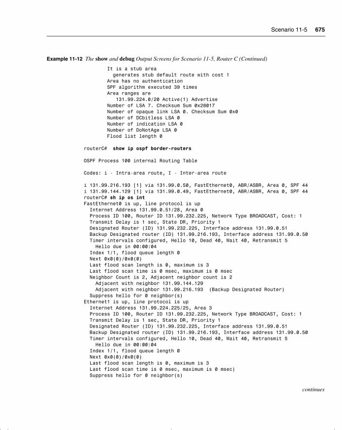
Scenario 11-5 675
It is a stub area generates stub default route with cost 1 Area has no authentication SPF algorithm executed 39 times Area ranges are 131.99.224.0/20 Active(1) Advertise Number of LSA 7. Checksum Sum 0x28017 Number of opaque link LSA 0. Checksum Sum 0x0 Number of DCbitless LSA 0 Number of indication LSA 0 Number of DoNotAge LSA 0 Flood list length 0 routerC# show ip ospf border-routers OSPF Process 100 internal Routing Table Codes: i - Intra-area route, I - Inter-area route i 131.99.216.193 [1] via 131.99.0.50, FastEthernet0, ABR/ASBR, Area 0, SPF 44i 131.99.144.129 [1] via 131.99.0.49, FastEthernet0, ABR/ASBR, Area 0, SPF 44routerC# sh ip os intFastEthernet0 is up, line protocol is up Internet Address 131.99.0.51/28, Area 0 Process ID 100, Router ID 131.99.232.225, Network Type BROADCAST, Cost: 1 Transmit Delay is 1 sec, State DR, Priority 1 Designated Router (ID) 131.99.232.225, Interface address 131.99.0.51 Backup Designated router (ID) 131.99.216.193, Interface address 131.99.0.50 Timer intervals configured, Hello 10, Dead 40, Wait 40, Retransmit 5 Hello due in 00:00:04 Index 1/1, flood queue length 0 Next 0x0(0)/0x0(0) Last flood scan length is 0, maximum is 3 Last flood scan time is 0 msec, maximum is 0 msec Neighbor Count is 2, Adjacent neighbor count is 2 Adjacent with neighbor 131.99.144.129 Adjacent with neighbor 131.99.216.193 (Backup Designated Router) Suppress hello for 0 neighbor(s)Ethernet1 is up, line protocol is up Internet Address 131.99.224.225/25, Area 3 Process ID 100, Router ID 131.99.232.225, Network Type BROADCAST, Cost: 1 Transmit Delay is 1 sec, State DR, Priority 1 Designated Router (ID) 131.99.232.225, Interface address 131.99.0.51 Backup Designated router (ID) 131.99.216.193, Interface address 131.99.0.50 Timer intervals configured, Hello 10, Dead 40, Wait 40, Retransmit 5 Hello due in 00:00:04 Index 1/1, flood queue length 0 Next 0x0(0)/0x0(0) Last flood scan length is 0, maximum is 3 Last flood scan time is 0 msec, maximum is 0 msec) Suppress hello for 0 neighbor(s)
continues
Example 11-12 The show and debug Output Screens for Scenario 11-5, Router C (Continued)
chpt_01.book Page 675 Thursday, December 21, 2000 6:22 PM
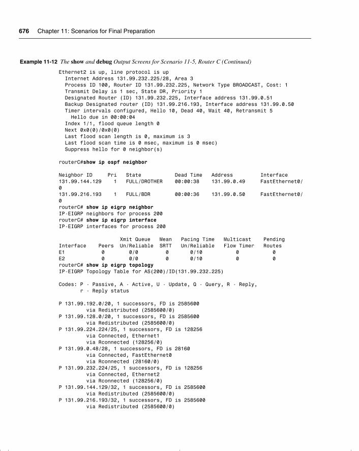
676 Chapter 11: Scenarios for Final Preparation
Ethernet2 is up, line protocol is up Internet Address 131.99.232.225/28, Area 3 Process ID 100, Router ID 131.99.232.225, Network Type BROADCAST, Cost: 1 Transmit Delay is 1 sec, State DR, Priority 1 Designated Router (ID) 131.99.232.225, Interface address 131.99.0.51 Backup Designated router (ID) 131.99.216.193, Interface address 131.99.0.50 Timer intervals configured, Hello 10, Dead 40, Wait 40, Retransmit 5 Hello due in 00:00:04 Index 1/1, flood queue length 0 Next 0x0(0)/0x0(0) Last flood scan length is 0, maximum is 3 Last flood scan time is 0 msec, maximum is 0 msec) Suppress hello for 0 neighbor(s)
routerC#show ip ospf neighbor Neighbor ID Pri State Dead Time Address Interface131.99.144.129 1 FULL/DROTHER 00:00:38 131.99.0.49 FastEthernet0/0131.99.216.193 1 FULL/BDR 00:00:36 131.99.0.50 FastEthernet0/0routerC# show ip eigrp neighborIP-EIGRP neighbors for process 200routerC# show ip eigrp interfaceIP-EIGRP interfaces for process 200 Xmit Queue Mean Pacing Time Multicast PendingInterface Peers Un/Reliable SRTT Un/Reliable Flow Timer RoutesE1 0 0/0 0 0/10 0 0E2 0 0/0 0 0/10 0 0routerC# show ip eigrp topologyIP-EIGRP Topology Table for AS(200)/ID(131.99.232.225) Codes: P - Passive, A - Active, U - Update, Q - Query, R - Reply, r - Reply status P 131.99.192.0/20, 1 successors, FD is 2585600 via Redistributed (2585600/0)P 131.99.128.0/20, 1 successors, FD is 2585600 via Redistributed (2585600/0)P 131.99.224.224/25, 1 successors, FD is 128256 via Connected, Ethernet1 via Rconnected (128256/0)P 131.99.0.48/28, 1 successors, FD is 28160 via Connected, FastEthernet0 via Rconnected (28160/0)P 131.99.232.224/25, 1 successors, FD is 128256 via Connected, Ethernet2 via Rconnected (128256/0)P 131.99.144.129/32, 1 successors, FD is 2585600 via Redistributed (2585600/0)P 131.99.216.193/32, 1 successors, FD is 2585600 via Redistributed (2585600/0)
Example 11-12 The show and debug Output Screens for Scenario 11-5, Router C (Continued)
chpt_01.book Page 676 Thursday, December 21, 2000 6:22 PM
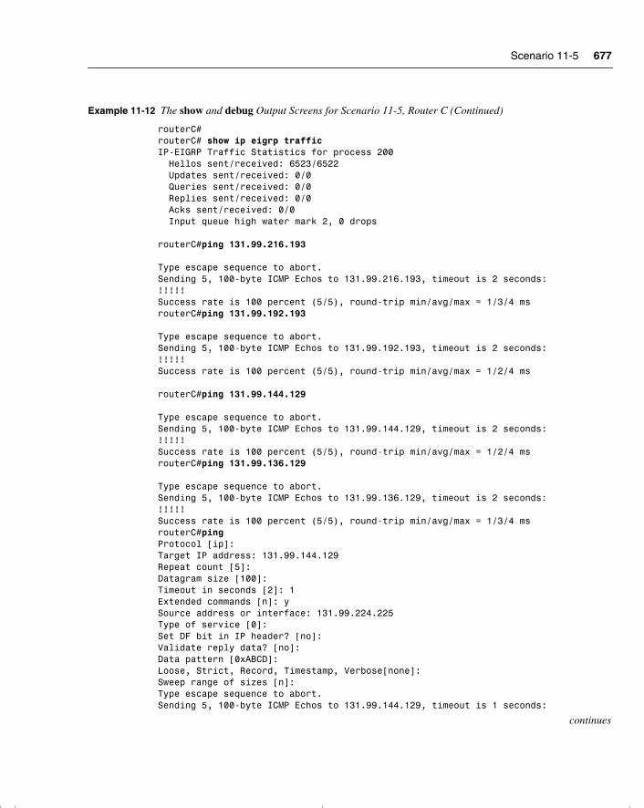
Scenario 11-5 677
routerC#routerC# show ip eigrp trafficIP-EIGRP Traffic Statistics for process 200 Hellos sent/received: 6523/6522 Updates sent/received: 0/0 Queries sent/received: 0/0 Replies sent/received: 0/0 Acks sent/received: 0/0 Input queue high water mark 2, 0 drops routerC#ping 131.99.216.193 Type escape sequence to abort.Sending 5, 100-byte ICMP Echos to 131.99.216.193, timeout is 2 seconds:!!!!!Success rate is 100 percent (5/5), round-trip min/avg/max = 1/3/4 msrouterC#ping 131.99.192.193 Type escape sequence to abort.Sending 5, 100-byte ICMP Echos to 131.99.192.193, timeout is 2 seconds:!!!!!Success rate is 100 percent (5/5), round-trip min/avg/max = 1/2/4 ms routerC#ping 131.99.144.129 Type escape sequence to abort.Sending 5, 100-byte ICMP Echos to 131.99.144.129, timeout is 2 seconds:!!!!!Success rate is 100 percent (5/5), round-trip min/avg/max = 1/2/4 msrouterC#ping 131.99.136.129 Type escape sequence to abort.Sending 5, 100-byte ICMP Echos to 131.99.136.129, timeout is 2 seconds:!!!!!Success rate is 100 percent (5/5), round-trip min/avg/max = 1/3/4 msrouterC#pingProtocol [ip]:Target IP address: 131.99.144.129Repeat count [5]:Datagram size [100]:Timeout in seconds [2]: 1Extended commands [n]: ySource address or interface: 131.99.224.225Type of service [0]:Set DF bit in IP header? [no]:Validate reply data? [no]:Data pattern [0xABCD]:Loose, Strict, Record, Timestamp, Verbose[none]:Sweep range of sizes [n]:Type escape sequence to abort.Sending 5, 100-byte ICMP Echos to 131.99.144.129, timeout is 1 seconds:
continues
Example 11-12 The show and debug Output Screens for Scenario 11-5, Router C (Continued)
chpt_01.book Page 677 Thursday, December 21, 2000 6:22 PM
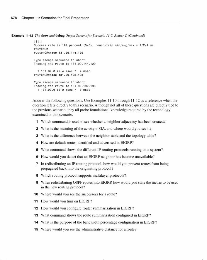
678 Chapter 11: Scenarios for Final Preparation
Answer the following questions. Use Examples 11-10 through 11-12 as a reference when the question refers directly to this scenario. Although not all of these questions are directly tied to the previous scenario, they all probe foundational knowledge required by the technology examined in this scenario.
1 Which command is used to see whether a neighbor adjacency has been created?
2 What is the meaning of the acronym SIA, and where would you see it?
3 What is the difference between the neighbor table and the topology table?
4 How are default routes identified and advertised in EIGRP?
5 What command shows the different IP routing protocols running on a system?
6 How would you detect that an EIGRP neighbor has become unavailable?
7 In redistributing an IP routing protocol, how would you prevent routes from being propagated back into the originating protocol?
8 Which routing protocol supports multilayer protocols?
9 When redistributing OSPF routes into EIGRP, how would you state the metric to be used in the new routing protocol?
10 Where would you see the successors for a route?
11 How would you turn on EIGRP?
12 How would you configure router summarization in EIGRP?
13 What command shows the route summarization configured in EIGRP?
14 What is the purpose of the bandwidth percentage configuration in EIGRP?
15 Where would you see the administrative distance for a route?
!!!!!Success rate is 100 percent (5/5), round-trip min/avg/max = 1/2/4 msrouterC#routerC#trace 131.99.144.129 Type escape sequence to abort.Tracing the route to 131.99.144.129 1 131.99.0.49 4 msec * 0 msecrouterC#trace 131.99.192.193 Type escape sequence to abort.Tracing the route to 131.99.192.193 1 131.99.0.50 0 msec * 0 msec
Example 11-12 The show and debug Output Screens for Scenario 11-5, Router C (Continued)
chpt_01.book Page 678 Thursday, December 21, 2000 6:22 PM
Scenario 11-5 679
16 Which debug command is used to identify that there is a problem in creating an adjacency in EIGRP?
17 What is the purpose of the subnet parameter in the EIGRP and OSPF redistribution command?
18 What routes can be redistributed into another routing protocol?
19 What is the difference between the in and the out parameters when set on a distribute list?
20 What should you consider in configuring EIGRP across an NBMA cloud?
Solutions to Scenario 11-5, Part C—Verification and QuestionsThe answers to the questions for Scenario 11-5, Part C are as follows:
1 Which command is used to see whether a neighbor adjacency has been created?
The command that shows whether an adjacency has been formed is show ip eigrp topology.
The part of the output from this command that shows the adjacency is seen in the codes.
Codes tell the state of the topology table entry. Passive and active refer to the EIGRP state, with respect to this destination. Update, query, and reply refer to the type of packet that is being sent. The codes are as follows:
• P—Passive: No Enhanced IGRP computations are being performed for this destination.
• A—Active: Enhanced IGRP computations are being performed for this destination.
• U—Update: Indicates that an update packet was sent to this destination.
• Q—Query: Indicates that a query packet was sent to this destination.
• R—Reply: Indicates that a reply packet was sent to this destination.
• r—Reply status: Is a flag that is set after the software has sent a query and is waiting for a reply.
• successors: Gives the Number of successors. This number corresponds to the number of next hops in the IP routing table.
• FD—Feasible distance: This value is used in the feasibility condition check. If the neighbor’s reported distance (the metric after the slash) is less than the feasible distance, the feasibility condition is met and that path is a feasible successor. When the software determines it has a feasible successor, it does not have to send a query for that destination.
chpt_01.book Page 679 Thursday, December 21, 2000 6:22 PM
680 Chapter 11: Scenarios for Final Preparation
• replies: Gives the number of replies that are still outstanding (that have not been received) with respect to this destination. This information appears only when the destination is in active state.
• state: Gives the exact Enhanced IGRP state that this destination is in. It can be the number 0, 1, 2, or 3. This information appears only when the destination is active.
• Via: Gives the IP address of the peer that told the software about this destination. The first N of these entries, where N is the number of successors, are the current successors. The remaining entries on the list are feasible successors.
2 What is the meaning of the acronym SIA, and where would you see it?
The acronym SIA stands for Stuck in Active, which means that an EIGRP neighbor has not replied to a query that was sent out. If the neighbor does not reply within a limited time, it is presumed dead and is flushed from the tables. This is to prevent a route from being permanently active as an alternative path is sought from unresponsive neighbors.
An error message will be generated to the screen, but it is possible to identify the problem by looking at the log files or issuing commands. In the show ip eigrp topology command, any neighbors that show an R have not yet replied (the active timer shows how long the route has been active) may be Stuck in Active. It is advisable to run this command several times; you begin to see which neighbors are not responding to queries (or which interfaces seem to have a lot of unanswered queries). You should also examine this neighbor to see if it is consistently waiting for replies from any of its neighbors. Repeat this process until you find the router that is consistently not answering queries.
The problems are often on the link to this neighbor, or with memory or CPU utilization with this neighbor.
It is often better to reduce the query range instead of increasing the SIA timer.
3 What is the difference between the neighbor table and the topology table?
The neighbor table holds information about EIGRP neighbors, while the topology table lists all the routes known to have feasible successors.
4 How are default routes identified and advertised in EIGRP?
Answer: Default routes are shown with the address 0.0.0.0 and are advertised as an external address. This affects the administrative distance.
5 What command shows the different IP routing protocols running on a system?
The command that shows all the different IP routing protocol running on a system is show ip protocols.
This shows the protocols, redistribution, and many other details.
chpt_01.book Page 680 Thursday, December 21, 2000 6:22 PM
Scenario 11-5 681
6 How would you detect that an EIGRP neighbor has become unavailable?
The command show ip eigrp topology would show that there had not been a reply to packets sent to the neighbor. The command show ip eigrp neighbors shows the neighbors, how long they have been in the table, and the last time they were heard from.
7 In redistributing an IP routing protocol, how would you prevent routes from being propagated back into the originating protocol?
This would be done by creating a distribute list that permits only those routes that did not originate from the protocol into which the updates are being redistributed.
8 Which routing protocol supports multilayer protocols?
EIGRP supports IP, AppleTalk, and IPX.
9 When redistributing OSPF routes into EIGRP, how would you state the metric to be used in the new routing protocol?
There are two ways of stating the metric to be used by the redistributed networks. The first is to include the metric on the redistribution command:
Router(config-router)#redistribute ospf 200 metric bandwidth delay reliability load mtu
This will give the stated metric to all routes sent to EIGRP from the routing process OSPF 200.
The other method is this command:
Router(config-router)# default-metric bandwidth delay reliability load mtu
This command assigns the same metric to all routes distributed into EIGRP from any source.
10 Where would you see the successors for a route?
The successors to a route are held in the routing table because it is the current next hop that is being used to forward traffic to the remote destination. The command that shows these successors is as follows:
Router# show ip route
11 How would you turn on EIGRP?
The command to turn on EIGRP is as follows:
Router(config)# router eigrp autonomous-system-number
This starts the routing process, while the following command identifies the interfaces that will receive, send, and advertise updates for that process:
Router(config-router)# network network number
chpt_01.book Page 681 Thursday, December 21, 2000 6:22 PM
682 Chapter 11: Scenarios for Final Preparation
12 How would you configure router summarization in EIGRP?
Route summarization can be configured in one of two ways in EIGRP. The first is to configure summarization within EIGRP. This is achieved at the interface level and allows great flexibility in configuration. The command is as follows:
Router(config-if)# ip summary-address eigrp autonomous-system-number network mask
The other method of summarizing routes is done when redistributing routes. The command is as follows:
Router(config-router)# ip summary-address eigrp autonomous-system-number
This specifies the summary address and mask, as well as the EIGRP process into which the summary is to be advertised.
13 What command shows the route summarization configured in EIGRP?
The command show ip route shows the summarization.
14 What is the purpose of the bandwidth percentage configuration in EIGRP?
The purpose of the bandwidth percentage configuration in EIGRP is to limit the amount of bandwidth that can be taken by EIGRP networking traffic. By default, this is limited to 50 percent of the link. In NBMA clouds—in particular, Frame Relay—it may be advisable to tune this parameter, depending on the CIR of the links.
15 Where would you see the administrative distance for a route?
The administrative distance of a route can be seen in the routing table. It is the second half of the number in brackets. The first number is the metric; the second is the administrative distance.
16 Which debug command is used to identify that there is problem in creating an adjacency in EIGRP?
This command
Router# debug ip eigrp neighbor autonomous-system-number address
adds a filter to this command
Router# debug ip eigrp packets
and displays only IP packets for the stated process and address.
17 What is the purpose of the subnet parameter in the EIGRP and OSPF redistribution command?
The subnet parameter in the EIGRP and OSPF redistribution commands allows the subnets of major networks that are not directly connected to be redistributed into the protocol. Without this, only major networks will be distributed.
chpt_01.book Page 682 Thursday, December 21, 2000 6:22 PM
Scenario 11-5 683
18 What routes can be redistributed into another routing protocol?
Static routes, directly connected routes, or routes learned dynamically from another routing protocol can be redistributed.
19 What is the difference between the in and the out parameters when set on a distribute list?
The in parameter determines routes entering a routing protocol. The out parameter defines the routes that can be redistributed into another routing protocol.
20 What should you consider in configuring EIGRP across an NBMA cloud?
When configuring EIGRP over NBMA clouds, you should consider the nature of the link. Is it point-to-point or multipoint? Also consider overhead traffic associated with EIGRP and bandwidth utilization:
• Over a point-to-point interface, set the bandwidth to reflect the CIR of the PVC.
• Over multipoint Frame Relay, ATM, SMDS, and ISDN PRI, the bandwidth is divided equally among the links. The configuration should reflect the percentage of the available bandwidth.
• If the PVCs have different CIRs, then either convert the links to point-to-point or configure the bandwidth to be a multiple of the lowest available CIR by the number of PVCs.
chpt_01.book Page 683 Thursday, December 21, 2000 6:22 PM

This appendix contains the answers to the “Do I Know This Already?” quizzes and “Q&A” questions. In some cases, multiple answers are correct. In those cases, the answer listed here is the best possible answer. Note that the answers to the “Scenarios” questions are at the end of each chapter.
chpt_01.book Page 684 Thursday, December 21, 2000 6:22 PM
A P P E N D I X A
Answers to Quiz Questions
Chapter 2
Chapter 2 “Do I Know This Already?” Quiz Answers1 List two symptoms of network congestion.
Symptoms of network congestion include these:
— Applications timing out at end stations
— Clients not being capable of connecting to network resources
— Network death
The causes of congestion are often the symptoms seen, and they include these:
— Excessive traffic, seen on the network-management tools
— The dropping of packets, seen on the router interfaces
— The retransmission of packets, seen on the network-management tools
— Incomplete routing tables, seen on the router
— Incomplete service tables, seen on servers and routers
— Broadcast storms caused by spanning tree
2 If a switch has redundant links to another switch, what action would be taken if the Spanning-Tree Protocol fails to see a bridge protocol data unit (BPDU) in time (within the MaxAge Timer value)?
If the Spanning-Tree Protocol fails to see the BPDU packet in time, it will unblock the redundant path, in the belief that the primary path is no longer available.
3 How could the dropping of packets cause an increase of traffic on the network?
The dropping of packets could increase the traffic on the network because the applications may request the retransmission of the packet. This is particularly true on a connection-orientated communication.
chpt_01.book Page 685 Thursday, December 21, 2000 6:22 PM
686 Appendix A: Answers to Quiz Questions
4 How might network congestion cause a loss of services?
Services may be lost when network congestion is experienced. The reasons include these:
— The input buffers of the server are overloaded.
— The application times out.
— The network traffic informing clients of services is lost or delayed sufficiently for the services to be dropped from the server lists.
5 In Cisco’s hierarchical design, what is the function of the core layer?
A layer is created by defining what needs to run through the layer. The core layer is defined by the need for a high-speed backbone linking the different sites, or logical groupings, of the network. It is the central internetwork for the entire enterprise and may include LAN and WAN backbones. The primary function of this layer is to provide an optimized and reliable transport structure.
6 In Cisco’s hierarchical design, where is the access layer located?
The access layer is the layer that is the closest to the end stations. The router keeps that local traffic local and therefore prevents unnecessary traffic from traversing the network. The access layer is designed to ensure that LAN traffic can be contained locally and does not travel off the network to create network congestion.
7 In the hierarchical design suggested by Cisco, at which layer are access lists not recommended?
Access lists are not recommended at the core layer because this is where the traffic should switch at the highest speeds. Because access lists are CPU-intensive (adding about 15 percent overhead), they are not recommended for use in the core layer. This is still true, despite the fact that the technology allows the access list to be cached for fast switching, because the general rule is that all decisions are made at the previous layers of the network.
8 What is the function of the distribution layer?
The distribution layer provides the demarcation point between the core and access layers, providing policy-based connectivity and allowing you to do packet manipulation.
9 If an access list is configured as an inbound list, will the packet be sent to the routing process?
The packet from an inbound access list will not be sent to the routing process if a match is found for the access list criteria, and the action is to deny the packet. The packet is discarded before it reaches the routing process.
chpt_01.book Page 686 Thursday, December 21, 2000 6:22 PM
Chapter 2 687
10 State three uses of access lists.
The following are all valid uses for access lists:
— Restricting networks sent out in routing updates
— Restricting connectivity to remote networks
— Restricting the services advertised in an IPX network
— Restricting large packet sizes from traversing the network
11 In an IP standard access list, what is the default wildcard mask?
The default wildcard mask in an IP standard access list is 0.0.0.0.
12 If a packet does not match any of the criteria in an access list, what action will be taken?
If the packet being tested against the access list does not match any of the criteria, it will hit the implicit deny all at the bottom of the access list. This results in it being discarded, generating an ICMP message to the sending station.
13 Why does the null interface not report an ICMP message stating that the packet is undeliverable?
The null interface does not report an ICMP message because there is no error to report. From the viewpoint of the routing process, the packet has been successfully routed to the outgoing interface. The routing process is unaware that the outgoing interface is a virtual interface that does not exist. Effectively, the packet has been sent to the dump, thus killing the packet.
14 How would you restrict Telnet connectivity to the router that you were configuring?
To restrict Telnet connections into the router that you are configuring, use access lists that are applied to the terminal lines with the access-class command.
15 Which of the queuing techniques offered by the Cisco IOS are manually configured?
The queuing techniques manually configured on a Cisco system are custom and priority queuing.
16 Explain ip helper address. What is its function?
ip helper address is a command that has the router forward User Datagram Protocol (UDP) broadcasts received on an interface to a directed or specific destination on another network.
Combined with the ip forward-protocol global configuration command, the ip helper-address command enables you to control which broadcast packets and which protocols are forwarded. One common application that requires helper addresses is Dynamic Host Configuration Protocol (DHCP). DHCP is defined in RFC 1531. DHCP protocol information is carried inside BOOTP packets. To enable BOOTP
chpt_01.book Page 687 Thursday, December 21, 2000 6:22 PM
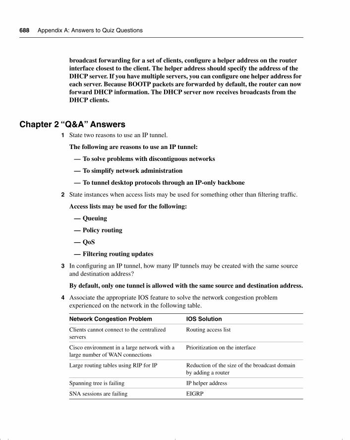
688 Appendix A: Answers to Quiz Questions
broadcast forwarding for a set of clients, configure a helper address on the router interface closest to the client. The helper address should specify the address of the DHCP server. If you have multiple servers, you can configure one helper address for each server. Because BOOTP packets are forwarded by default, the router can now forward DHCP information. The DHCP server now receives broadcasts from the DHCP clients.
Chapter 2 “Q&A” Answers1 State two reasons to use an IP tunnel.
The following are reasons to use an IP tunnel:
— To solve problems with discontiguous networks
— To simplify network administration
— To tunnel desktop protocols through an IP-only backbone
2 State instances when access lists may be used for something other than filtering traffic.
Access lists may be used for the following:
— Queuing
— Policy routing
— QoS
— Filtering routing updates
3 In configuring an IP tunnel, how many IP tunnels may be created with the same source and destination address?
By default, only one tunnel is allowed with the same source and destination address.
4 Associate the appropriate IOS feature to solve the network congestion problem experienced on the network in the following table.
Network Congestion Problem IOS Solution
Clients cannot connect to the centralized servers
Routing access list
Cisco environment in a large network with a large number of WAN connections
Prioritization on the interface
Large routing tables using RIP for IP Reduction of the size of the broadcast domain by adding a router
Spanning tree is failing IP helper address
SNA sessions are failing EIGRP
chpt_01.book Page 688 Thursday, December 21, 2000 6:22 PM
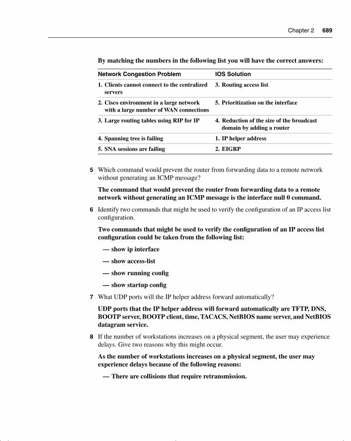
Chapter 2 689
By matching the numbers in the following list you will have the correct answers:
5 Which command would prevent the router from forwarding data to a remote network without generating an ICMP message?
The command that would prevent the router from forwarding data to a remote network without generating an ICMP message is the interface null 0 command.
6 Identify two commands that might be used to verify the configuration of an IP access list configuration.
Two commands that might be used to verify the configuration of an IP access list configuration could be taken from the following list:
— show ip interface
— show access-list
— show running config
— show startup config
7 What UDP ports will the IP helper address forward automatically?
UDP ports that the IP helper address will forward automatically are TFTP, DNS, BOOTP server, BOOTP client, time, TACACS, NetBIOS name server, and NetBIOS datagram service.
8 If the number of workstations increases on a physical segment, the user may experience delays. Give two reasons why this might occur.
As the number of workstations increases on a physical segment, the user may experience delays because of the following reasons:
— There are collisions that require retransmission.
Network Congestion Problem IOS Solution
1. Clients cannot connect to the centralized servers
3. Routing access list
2. Cisco environment in a large network with a large number of WAN connections
5. Prioritization on the interface
3. Large routing tables using RIP for IP 4. Reduction of the size of the broadcast domain by adding a router
4. Spanning tree is failing 1. IP helper address
5. SNA sessions are failing 2. EIGRP
chpt_01.book Page 689 Thursday, December 21, 2000 6:22 PM
690 Appendix A: Answers to Quiz Questions
— There is packet loss because buffers on devices are overflowing and require retransmission.
— The end systems could be slowing down because of excessive broadcast traffic.
9 State three considerations when deciding where to place extended IP access lists.
You should consider at least three of the following:
— Minimize the distance that denied traffic must travel. Place the access list as close to the source as possible.
— Keep the denied traffic off the backbone connecting buildings or campuses.
— Ensure that the router chosen can deal easily with the additional CPU requirements.
— Consider the CPU utilization because an inbound access list does not have to do a routing update on denied traffic. However, the interface may have to match the access list against more traffic.
— Consider the number of interfaces affected.
— Consider the number of nodes affected. Outbound access lists may afford greater granularity.
— Consider access list management.
— Consider the network growth and the effect on the management of the interfaces and the changing needs in connectivity.
10 What is the function of the access layer?
The function of the access layer is to act as the first point of contact for the end devices or workstations. It also acts as a filter layer to ensure that all local traffic stays local and does not unnecessarily clog the network.
11 What is the access list number range for IP extended access lists?
The extended access list number range is 100 to 199.
12 What is priority queuing?
Priority queuing enables network managers to define how they want traffic to be prioritized in the network. By defining a series of filters based on packet characteristics, traffic is placed into a number of queues; the queue with the highest priority is serviced first, and then the lower queues are serviced in sequence. If the highest-priority queue is always full, this queue will continually be serviced, and packets from the other queues will queue up and be dropped. In this queuing algorithm, one particular kind of network traffic can dominate all others. Priority queuing assigns traffic to one of four queues: high, medium, normal, and low.
chpt_01.book Page 690 Thursday, December 21, 2000 6:22 PM
Chapter 2 691
13 List two symptoms of network congestion.
Symptoms of network congestion include these:
— Applications timing out at end stations
— Clients not being capable of connecting to network resources
— Network death resulting
The causes of congestion are often the symptoms seen, and they include these:
— Excessive traffic, seen on the network-management tools
— Dropped packets, seen on the router interfaces
— The retransmission of packets, seen on the network-management tools
— Incomplete routing tables, seen on the router
— Incomplete service tables, seen on servers and routers
— Broadcast storms caused by spanning tree
14 If a switch has redundant links to another switch, what action would be taken if the Spanning-Tree Protocol fails to see a BPDU in time (within the MaxAge Timer value)?
If the Spanning-Tree Protocol fails to see the BPDU packet in time, it will unblock the redundant path, in the belief that the primary path is no longer available.
15 How could the dropping of packets cause an increase of traffic on the network?
The dropping of packets could increase the traffic on the network because the applications may request the retransmission of the packet. This is particularly true on a connection-orientated communication.
16 How might network congestion cause a loss of services?
Services may be lost when network congestion is experienced. The reasons include these:
— The input buffers of the server are overloaded.
— The application times out.
— The network traffic informing clients of services is lost or delayed sufficiently for the services to be dropped from the server lists.
17 In Cisco’s hierarchical design, what is the function of the core layer?
A layer is created by defining what needs to run through the layer. The core layer is defined by the need for a high-speed backbone linking the different sites, or logical groupings, of the network. It is the central internetwork for the entire enterprise and may include LAN and WAN backbones. The primary function of this layer is to provide an optimized and reliable transport structure.
chpt_01.book Page 691 Thursday, December 21, 2000 6:22 PM
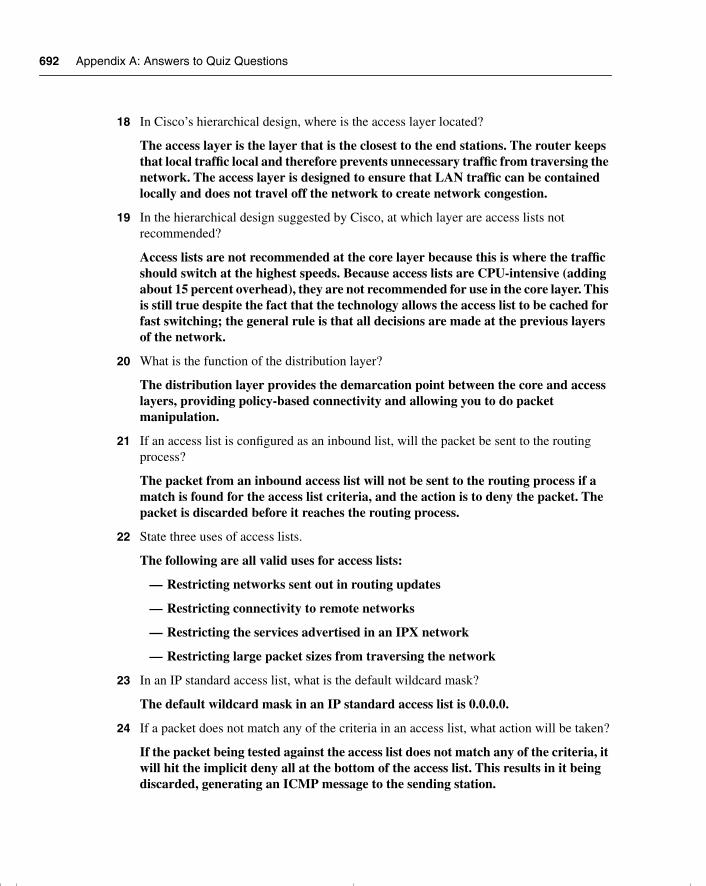
692 Appendix A: Answers to Quiz Questions
18 In Cisco’s hierarchical design, where is the access layer located?
The access layer is the layer that is the closest to the end stations. The router keeps that local traffic local and therefore prevents unnecessary traffic from traversing the network. The access layer is designed to ensure that LAN traffic can be contained locally and does not travel off the network to create network congestion.
19 In the hierarchical design suggested by Cisco, at which layer are access lists not recommended?
Access lists are not recommended at the core layer because this is where the traffic should switch at the highest speeds. Because access lists are CPU-intensive (adding about 15 percent overhead), they are not recommended for use in the core layer. This is still true despite the fact that the technology allows the access list to be cached for fast switching; the general rule is that all decisions are made at the previous layers of the network.
20 What is the function of the distribution layer?
The distribution layer provides the demarcation point between the core and access layers, providing policy-based connectivity and allowing you to do packet manipulation.
21 If an access list is configured as an inbound list, will the packet be sent to the routing process?
The packet from an inbound access list will not be sent to the routing process if a match is found for the access list criteria, and the action is to deny the packet. The packet is discarded before it reaches the routing process.
22 State three uses of access lists.
The following are all valid uses for access lists:
— Restricting networks sent out in routing updates
— Restricting connectivity to remote networks
— Restricting the services advertised in an IPX network
— Restricting large packet sizes from traversing the network
23 In an IP standard access list, what is the default wildcard mask?
The default wildcard mask in an IP standard access list is 0.0.0.0.
24 If a packet does not match any of the criteria in an access list, what action will be taken?
If the packet being tested against the access list does not match any of the criteria, it will hit the implicit deny all at the bottom of the access list. This results in it being discarded, generating an ICMP message to the sending station.
chpt_01.book Page 692 Thursday, December 21, 2000 6:22 PM
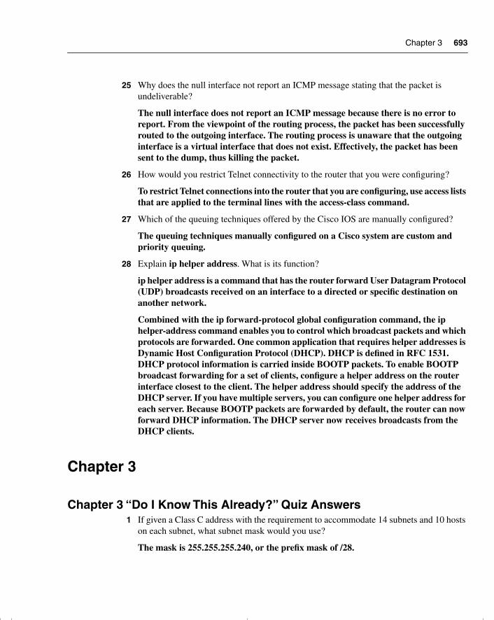
Chapter 3 693
25 Why does the null interface not report an ICMP message stating that the packet is undeliverable?
The null interface does not report an ICMP message because there is no error to report. From the viewpoint of the routing process, the packet has been successfully routed to the outgoing interface. The routing process is unaware that the outgoing interface is a virtual interface that does not exist. Effectively, the packet has been sent to the dump, thus killing the packet.
26 How would you restrict Telnet connectivity to the router that you were configuring?
To restrict Telnet connections into the router that you are configuring, use access lists that are applied to the terminal lines with the access-class command.
27 Which of the queuing techniques offered by the Cisco IOS are manually configured?
The queuing techniques manually configured on a Cisco system are custom and priority queuing.
28 Explain ip helper address. What is its function?
ip helper address is a command that has the router forward User Datagram Protocol (UDP) broadcasts received on an interface to a directed or specific destination on another network.
Combined with the ip forward-protocol global configuration command, the ip helper-address command enables you to control which broadcast packets and which protocols are forwarded. One common application that requires helper addresses is Dynamic Host Configuration Protocol (DHCP). DHCP is defined in RFC 1531. DHCP protocol information is carried inside BOOTP packets. To enable BOOTP broadcast forwarding for a set of clients, configure a helper address on the router interface closest to the client. The helper address should specify the address of the DHCP server. If you have multiple servers, you can configure one helper address for each server. Because BOOTP packets are forwarded by default, the router can now forward DHCP information. The DHCP server now receives broadcasts from the DHCP clients.
Chapter 3
Chapter 3 “Do I Know This Already?” Quiz Answers1 If given a Class C address with the requirement to accommodate 14 subnets and 10 hosts
on each subnet, what subnet mask would you use?
The mask is 255.255.255.240, or the prefix mask of /28.
chpt_01.book Page 693 Thursday, December 21, 2000 6:22 PM

694 Appendix A: Answers to Quiz Questions
2 List the range of hosts available on the 136.122.10.192/28 subnet.
The range of hosts available on the subnet 136.122.10.192 /28 are 136.122.10.193–206.
3 Convert the subnet address 56.98.5.0/24 to binary notation, and state the class to which it belongs.
The Class A subnet 56.98.5.0, when converted to binary notation, is as follows:
00111000.01100010.00000101.00000000
4 Write out the decimal notation of the following subnet mask presented in this binary notation:
11111111.11111111.11111111.11111000
The decimal notation of the subnet mask would be 255.255.255.248.
5 What does VLSM stand for?
VLSM stands for variable-length subnet mask.
6 The Class B network address of 133.222.0.0 has been given a mask of 255.255.255.0. The subnets, 133.222.8.0, 133.222.9.0, 133.222.10.0, 133.222.11.0, 133.222.12.0, 133.222.13.0, and 133.222.14.0 need to be summarized using VLSM. Give the subnet and new mask to achieve this summarization.
The subnet would be 133.222.8.0 with a mask of 255.255.248.0, or /21.
7 Is 201.111.16.0/20 a valid subnet mask?
Yes, this is a valid mask, and it will provide 16 consecutive Class C addresses to the organization.
8 Which routing protocols support VLSM?
RIPv2, OSPF, IS-IS, EIGRP, BGP-4.
9 Briefly define route summarization.
Route summarization is the method of including many subnets in a few routing entries.
10 What sort of design scheme does route summarization require?
Route summarization requires a hierarchical addressing scheme.
11 In route summarization, where is the subnet mask moved?
In route summarization, the subnet mask is moved to the left.
12 How does summarization allow for smaller routing tables?
Summarizing is the consolidation of multiple routes into one single advertisement.
chpt_01.book Page 694 Thursday, December 21, 2000 6:22 PM
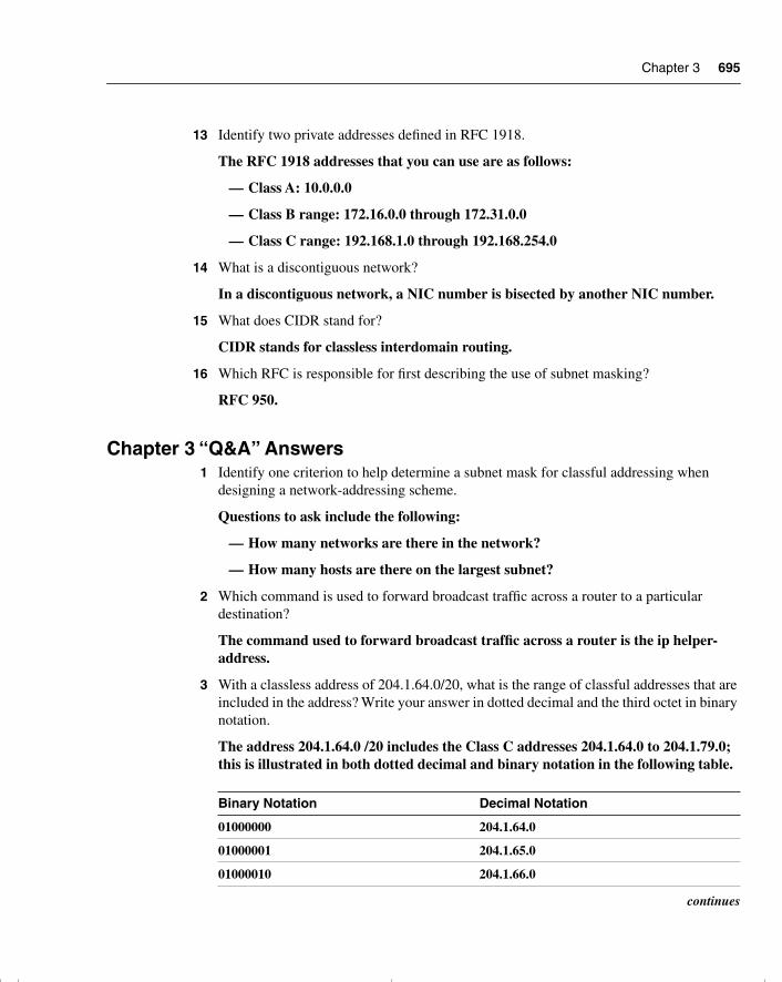
Chapter 3 695
13 Identify two private addresses defined in RFC 1918.
The RFC 1918 addresses that you can use are as follows:
— Class A: 10.0.0.0
— Class B range: 172.16.0.0 through 172.31.0.0
— Class C range: 192.168.1.0 through 192.168.254.0
14 What is a discontiguous network?
In a discontiguous network, a NIC number is bisected by another NIC number.
15 What does CIDR stand for?
CIDR stands for classless interdomain routing.
16 Which RFC is responsible for first describing the use of subnet masking?
RFC 950.
Chapter 3 “Q&A” Answers1 Identify one criterion to help determine a subnet mask for classful addressing when
designing a network-addressing scheme.
Questions to ask include the following:
— How many networks are there in the network?
— How many hosts are there on the largest subnet?
2 Which command is used to forward broadcast traffic across a router to a particular destination?
The command used to forward broadcast traffic across a router is the ip helper-address.
3 With a classless address of 204.1.64.0/20, what is the range of classful addresses that are included in the address? Write your answer in dotted decimal and the third octet in binary notation.
The address 204.1.64.0 /20 includes the Class C addresses 204.1.64.0 to 204.1.79.0; this is illustrated in both dotted decimal and binary notation in the following table.
Binary Notation Decimal Notation
01000000 204.1.64.0
01000001 204.1.65.0
01000010 204.1.66.0
continues
chpt_01.book Page 695 Thursday, December 21, 2000 6:22 PM
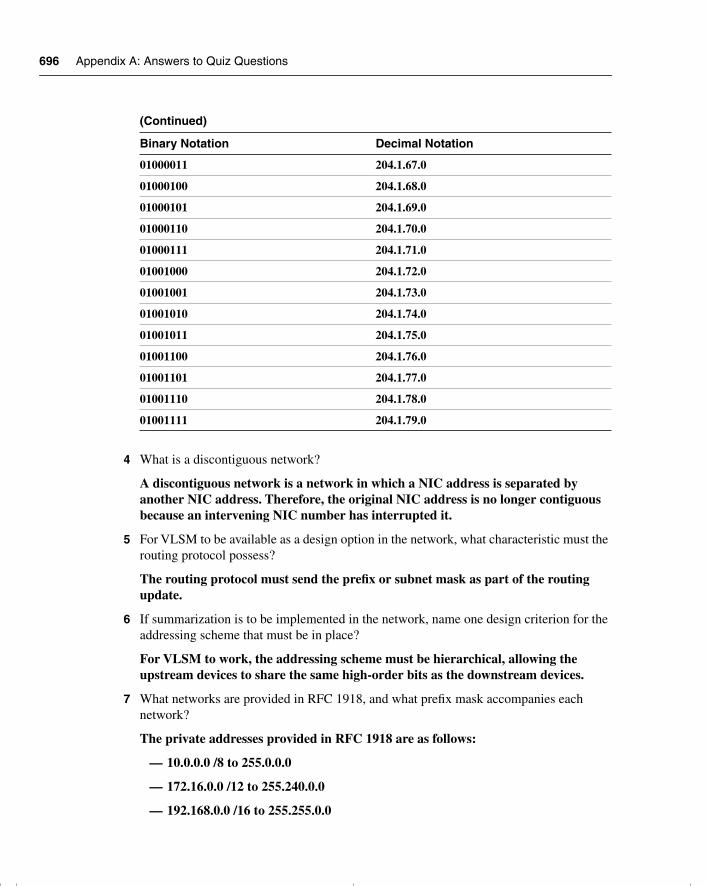
696 Appendix A: Answers to Quiz Questions
4 What is a discontiguous network?
A discontiguous network is a network in which a NIC address is separated by another NIC address. Therefore, the original NIC address is no longer contiguous because an intervening NIC number has interrupted it.
5 For VLSM to be available as a design option in the network, what characteristic must the routing protocol possess?
The routing protocol must send the prefix or subnet mask as part of the routing update.
6 If summarization is to be implemented in the network, name one design criterion for the addressing scheme that must be in place?
For VLSM to work, the addressing scheme must be hierarchical, allowing the upstream devices to share the same high-order bits as the downstream devices.
7 What networks are provided in RFC 1918, and what prefix mask accompanies each network?
The private addresses provided in RFC 1918 are as follows:
— 10.0.0.0 /8 to 255.0.0.0
— 172.16.0.0 /12 to 255.240.0.0
— 192.168.0.0 /16 to 255.255.0.0
01000011 204.1.67.0
01000100 204.1.68.0
01000101 204.1.69.0
01000110 204.1.70.0
01000111 204.1.71.0
01001000 204.1.72.0
01001001 204.1.73.0
01001010 204.1.74.0
01001011 204.1.75.0
01001100 204.1.76.0
01001101 204.1.77.0
01001110 204.1.78.0
01001111 204.1.79.0
(Continued)
Binary Notation Decimal Notation
chpt_01.book Page 696 Thursday, December 21, 2000 6:22 PM
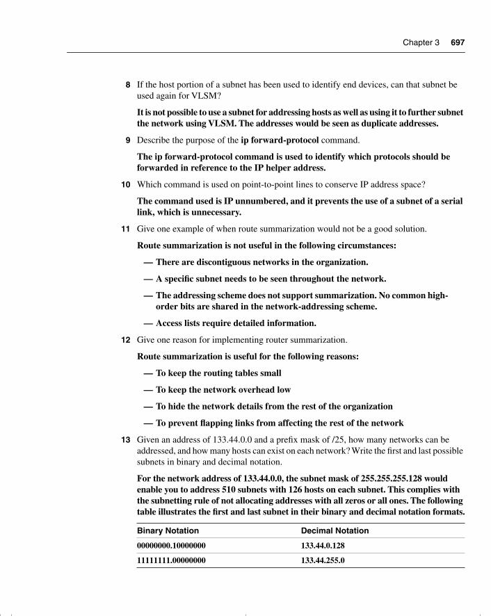
Chapter 3 697
8 If the host portion of a subnet has been used to identify end devices, can that subnet be used again for VLSM?
It is not possible to use a subnet for addressing hosts as well as using it to further subnet the network using VLSM. The addresses would be seen as duplicate addresses.
9 Describe the purpose of the ip forward-protocol command.
The ip forward-protocol command is used to identify which protocols should be forwarded in reference to the IP helper address.
10 Which command is used on point-to-point lines to conserve IP address space?
The command used is IP unnumbered, and it prevents the use of a subnet of a serial link, which is unnecessary.
11 Give one example of when route summarization would not be a good solution.
Route summarization is not useful in the following circumstances:
— There are discontiguous networks in the organization.
— A specific subnet needs to be seen throughout the network.
— The addressing scheme does not support summarization. No common high-order bits are shared in the network-addressing scheme.
— Access lists require detailed information.
12 Give one reason for implementing router summarization.
Route summarization is useful for the following reasons:
— To keep the routing tables small
— To keep the network overhead low
— To hide the network details from the rest of the organization
— To prevent flapping links from affecting the rest of the network
13 Given an address of 133.44.0.0 and a prefix mask of /25, how many networks can be addressed, and how many hosts can exist on each network? Write the first and last possible subnets in binary and decimal notation.
For the network address of 133.44.0.0, the subnet mask of 255.255.255.128 would enable you to address 510 subnets with 126 hosts on each subnet. This complies with the subnetting rule of not allocating addresses with all zeros or all ones. The following table illustrates the first and last subnet in their binary and decimal notation formats.
Binary Notation Decimal Notation
00000000.10000000 133.44.0.128
11111111.00000000 133.44.255.0
chpt_01.book Page 697 Thursday, December 21, 2000 6:22 PM
698 Appendix A: Answers to Quiz Questions
14 What class of address is 131.188.0.0, and how many hosts can be addressed if no subnetting is used?
131.188.0.0 is a Class B address and can address more than 65,000 hosts on one network if no subnetting is utilized.
15 If given a Class C address with the requirement to accommodate 14 subnets and 10 hosts on each subnet, what subnet mask would you use?
The mask is 255.255.255.240, or the prefix mask of /28.
16 List the range of hosts available on the 136.122.10.192/28 subnet.
The range of hosts available on the subnet 136.122.10.192 /28 is 136.122.10.193 to 206.
17 Convert the subnet address 56.98.5.0/24 to binary notation, and state the class to which it belongs.
The Class A subnet 56.98.5.0 when converted to binary notation is as follows:
00111000.01100010.00000101.00000000
18 Write out the decimal notation of the following subnet mask presented in the binary notation of 11111111.11111111.11111111.11111000.
The decimal notation of the subnet mask would be 255.255.255.248
19 What does VLSM stand for?
VLSM stands for variable-length subnet mask.
20 The Class B network address of 133.222.0.0 has been given a mask of 255.255.255.0. The subnets 133.222.8.0, 133.222.9.0, 133.222.10.0, 133.222.11.0, 133.222.12.0, 133.222.13.0, and 133.222.14.0 need to be summarized using VLSM. Give the subnet and new mask to achieve this summarization.
The subnet would be 133.222.8.0 with a mask of 255.255.248.0, or /21.
21 Is 201.111.16.0/20 a valid subnet mask?
Yes, this is a valid mask, and it will provide 16 consecutive Class C addresses to the organization.
22 Which routing protocols support VLSM?
RIPv2, OSPF, IS-IS, EIGRP, and BGP-4 support VLSM.
23 Briefly define route summarization.
Route summarization is the method of including many subnets in a few routing entries.
24 What sort of design scheme does route summarization require?
Route summarization requires a hierarchical addressing scheme.
chpt_01.book Page 698 Thursday, December 21, 2000 6:22 PM
Chapter 4 699
25 In route summarization, where is the subnet mask moved?
In route summarization, the subnet mask is moved to the left.
26 How does summarization allow for smaller routing tables?
Summarizing is the consolidation of multiple routes into a single advertisement.
27 Identify two private addresses defined in RFC 1918.
The RFC 1918 addresses that you can use are as follows:
— Class A: 10.0.0.0
— Class B range: 172.16.0.0 through 172.31.0.0
— Class C range: 192.168.1.0 through 192.168.254.0
28 What is a discontiguous network?
A discontiguous network is a network in which a NIC number is bisected by another NIC number.
29 What does CIDR stand for?
CIDR stands for classless interdomain routing.
30 Which RFC is responsible for first describing the use of subnet masking?
RFC 950 is responsible for this.
Chapter 4
Chapter 4 “Do I Know This Already?” Quiz Answers1 Cisco distinguishes between the routing and the switching function—what is the
difference?
The routing function is how the router learns the logical topology of the network. It decides whether the datagram can be routed, which path to select if there is a choice, and to which outgoing interface to queue the datagram. It operates at Layer 3 of the OSI stack.
The switching function is the forwarding of the frame from the inbound interface to an outbound interface. It operates at Layer 2 of the OSI stack, not at Layer 3, like a router.
A LAN switch connects two or more LAN segments. It uses a table of MAC addresses to determine the segment on which a frame needs to be transmitted; if it is on the interface that the frame received, then the frame is dropped. The switch listens to all
chpt_01.book Page 699 Thursday, December 21, 2000 6:22 PM
700 Appendix A: Answers to Quiz Questions
traffic on the interface, at Layer 2, while the router looks at only the MAC address of a multicast group of which it is a member, a broadcast, or its own individual MAC address. Switches operate at much higher speeds than routers, and can support new functionality, such as virtual LANs.
2 State the two ways that an outgoing interface is selected as the preferred path.
An outgoing interface is selected for the following reasons:
— Because it is the only available path
— Because the administrative distance is lower
— Because the metric is lower
3 What is administrative distance?
Administrative distance is the mechanism used by the routing process to select a path offered by two different routing protocols. The administrative distance is a set of values, in which a value is given to each IP routing protocol. This allows a hierarchy to be established so that when multiple protocols offer a path to the same remote network, one path can be chosen. The path that is chosen will be the one offered by the routing protocol with the lowest administrative distance. The administrative distance can be manually configured.
4 If IGRP has three paths to a remote network in which each path has an equal metric, what will happen?
If IGRP sees equal-cost paths to a remote network, it will load balance between those paths by default.
5 Name the interior IP routing protocols that send the mask with the routing update.
The interior IP routing protocols that send the mask with the routing update are EIGRP, OSPF, IS-IS, and RIPv2.
6 Name the interior routing protocol that sends a routing update on a Cisco router every 30 seconds by default.
The routing protocol that sends a routing update every 30 seconds is RIP.
7 Does VLSM require a classful or classless routing protocol, and why?
VLSM requires a classless routing protocol because it needs the subnet mask to be sent with the update.
chpt_01.book Page 700 Thursday, December 21, 2000 6:22 PM
Chapter 4 701
8 State one of the characteristics of a classful routing protocol.
The characteristics of a classful routing protocol are as follows:
— It summarizes at the network boundary.
— Routes exchanged between foreign networks are summarized to the NIC number.
— Within the same network (NIC number), subnet routes are exchanged by routers.
— All the interfaces on all the routers within a NIC number must share the same subnet mask.
— VLSM is not possible within the network.
9 A distance vector routing protocol uses the mechanism of poison reverse—what is this?
When the routing process suspects that a route in its routing table is no longer valid, it will set the metric so high for that route that it will render it unusable. This will be propagated in the routing updates to other routers.
10 Name two distance vector routing protocols.
Distance vector routing protocols include RIPv1, RIPv2, IGRP, and EIGRP (an advanced distance vector routing protocol).
11 Name two link-state IP routing protocols.
Link-state IP routing protocols include OSPF, IS-IS, and EIGRP (an advanced distance vector routing protocol with some link-state characteristics).
12 Describe the mechanism of split horizon.
Split horizon is a routing technique in which information about routes is prevented from exiting the router interface through which that information was received. Split-horizon updates are useful in preventing routing loops.
13 What is the command syntax to empty the Cisco routing table of all its routes?
The command syntax to empty the Cisco routing table of all of its routes is as follows:
clear ip route *
(This command must be executed from the privileged EXEC level.)
14 What does 0.0.0.0 signify in an IP routing table?
0.0.0.0 is used to signify the default route in the routing table.
chpt_01.book Page 701 Thursday, December 21, 2000 6:22 PM
702 Appendix A: Answers to Quiz Questions
15 What is the command to show whether a specific network, such as 141.131.6.16, is present in the routing table?
The command to show whether a specific network, such as 141.131.6.16, is present in the routing table is as follows:
show ip route 141.131.6.16
16 What is the next logical hop in the routing table?
The next logical hop in the routing table is the address of the interface to which traffic should be sent for it to reach the remote network. The address is taken from the source address of the routing update that provided the remote network.
Chapter 4 “Q&A” Answers1 Name one routing protocol that sends periodic updates.
RIPv1, RIPv2, and IGRP all send periodic updates.
2 What is an incremental update, and how often is it sent out?
An incremental update is an update that is sent out only when there is a change in the network. It contains only the information about the change. The change could be either the loss of a network or the addition of a network. Protocols that send incremental updates are link-state protocols, such as OSPF, IS-IS, BGP, and EIGRP, although not only link-state protocols will send incremental updates.
3 What is the routing algorithm used in OSPF?
The routing algorithm used in OSPF is the Dijkstra algorithm.
4 State one method by which a link-state routing protocol attempts to reduce the network overhead.
Link-state routing protocols reduce network overhead by sending only incremental updates, or periodic updates with a very long interval. The updates contain information about the links connecting local routers rather than route information that is calculated as part of the routing process.
5 Distance vector routing protocols naturally summarize at which boundary?
Distance vector routing protocols naturally summarize at the NIC or major network boundary. They do this by following the first octet rule.
6 Which routing protocol technology uses the Bellman Ford algorithm?
The routing protocol technology that uses Bellman Ford is distance vector technology.
chpt_01.book Page 702 Thursday, December 21, 2000 6:22 PM
Chapter 4 703
7 Give three reasons why RIPv1 has problems with working in a large network.
RIPv1 has problems working in a large network because of the following reasons:
— It has a maximum hop count of 15.
— It sends updates of its routing table out of every interface every 30 seconds, which increases the network overhead on a network and leads to link congestion.
— To avoid routing loops, it uses holddown and poison reverse, and thereby increases the time that it takes to propagate the changes in the network.
8 What is the Dijkstra algorithm used for?
The Dijkstra algorithm is used to calculate the shortest path first from the topological database. It examines the topological database and creates the routing table with the best path to each remote subnet. If there is more than one equal-cost path, it will load balance among them.
9 What is the destination address of the distance vector periodic update?
The destination address of the distance vector periodic update is 255.255.255.255 (the broadcast address).
10 State one major difference between a classful and classless routing protocol.
Major differences between a classful and classless routing protocol include these:
— The capability to use VLSM
— The capability to summarize
— The capability to maximize the logical address space
11 In the routing table, a field indicates the source of the routing information. If the field showed the letter C, what would this mean?
A field showing the letter C would mean that the network is directly connected.
12 In the routing table, how is the next logical hop indicated?
In the routing table, the next logical hop is indicated by the word via followed by an IP address. This is the address of the next logical hop.
13 Cisco distinguishes between the routing and the switching function—what is the difference?
The routing function is how the router learns the logical topology of the network. It decides whether the datagram can be routed, which path to select if there is a choice, and to which outgoing interface to queue the datagram. It operates at Layer 3 of the OSI stack.
chpt_01.book Page 703 Thursday, December 21, 2000 6:22 PM
704 Appendix A: Answers to Quiz Questions
The switching function is the forwarding of the frame from the inbound interface to an outbound interface. It operates at Layer 2 of the OSI stack, not at Layer 3, like a router.
A LAN switch connects two or more LAN segments. It uses a table of MAC addresses to determine the segment on which a frame needs to be transmitted; if it is on the interface that the frame received, then the frame is dropped. The switch listens to all traffic on the interface, at Layer 2, while the router looks at only the MAC address of a multicast group of which it is a member, a broadcast, or its own individual MAC address. Switches operate at much higher speeds than routers and can support new functionality, such as virtual LANs.
14 State the two ways that an outgoing interface is selected as the preferred path.
An outgoing interface is selected for the following reasons:
— Because it is the only available path
— Because the administrative distance is lower
— Because the metric is lower
15 What is administrative distance?
Administrative distance is the mechanism used by the routing process to select a path offered by two different routing protocols. The administrative distance is a set of values, in which a value is given to each IP routing protocol. This allows a hierarchy to be established so that when multiple protocols offer a path to the same remote network, one path can be chosen. The path that is chosen will be the one offered by the routing protocol with the lowest administrative distance. The administrative distance can be manually configured.
16 If IGRP has three paths to a remote network in which each path has an equal metric, what will happen?
If IGRP sees equal cost paths to a remote network, it will load balance between those paths by default.
17 Name the interior IP routing protocols that send the mask with the routing update.
The interior IP routing protocols that send the mask with the routing update are EIGRP, OSPF, IS-IS, and RIPv2.
18 Name the interior routing protocol that sends a routing update on a Cisco router every 30 seconds by default.
The routing protocol that sends a routing update every 30 seconds is RIP.
chpt_01.book Page 704 Thursday, December 21, 2000 6:22 PM
Chapter 4 705
19 Does VLSM require a classful or classless routing protocol, and why?
VLSM requires a classless routing protocol because it needs the subnet mask to be sent with the update.
20 State one of the characteristics of a classful routing protocol.
The characteristics of a classful routing protocol are as follows:
— It summarizes at the network boundary.
— Routes exchanged between foreign networks are summarized to the NIC number.
— Within the same network (NIC number), subnet routes are exchanged by routers.
— All the interfaces on all the routers within a NIC number must share the same subnet mask.
— VLSM is not possible within the network.
21 A distance vector routing protocol uses the mechanism of poison reverse—what is this?
When the routing process suspects that a route in its routing table is no longer valid, it sets the metric so high for that route that it renders it unusable. This will be propagated in the routing updates to other routers.
22 Name two distance vector routing protocols.
Distance vector routing protocols include RIPv1, RIPv2, IGRP, and EIGRP (an advanced distance vector routing protocol).
23 Name two link-state IP routing protocols.
Link-state IP routing protocols include OSPF, IS-IS, and EIGRP (an advanced distance vector routing protocol, with some link-state characteristics).
24 Describe the mechanism of split horizon.
Split horizon is a routing technique in which information about routes is prevented from exiting the router interface through which that information was received. Split-horizon updates are useful in preventing routing loops.
25 What is the command syntax to empty the Cisco routing table of all its routes?
The command syntax to empty the Cisco routing table of all its routes is as follows:
clear ip route *
(This command must be executed from the privileged EXEC level.)
chpt_01.book Page 705 Thursday, December 21, 2000 6:22 PM
706 Appendix A: Answers to Quiz Questions
26 What does 0.0.0.0 signify in an IP routing table?
0.0.0.0 is used to signify the default route in the routing table.
27 What is the command to show whether a specific network, such as 141.131.6.16, is present in the routing table?
The command to show whether a specific network, such as 141.131.6.16, is present in the routing table is as follows:
show ip route 141.131.6.16
28 What is the next logical hop in the routing table?
The next logical hop in the routing table is the address of the interface to which traffic should be sent for it to reach the remote network. The address is taken from the source address of the routing update that provided the remote network.
Chapter 5
Chapter 5 “Do I Know This Already?” Quiz Answers1 How often, by default, does OSPF send out hello packets on a broadcast multiaccess link?
By default, OSPF sends out hello packets every 10 seconds on a broadcast network.
2 What is a neighbor in OSPF?
A neighbor is a router on the same network link.
3 What is an adjacency in OSPF?
An adjacency is the state that two neighbors can achieve after they have synchronized their OSPF databases.
4 If the network is stable and sees no changes, how often will it send LSAs? Why are these updates sent out periodically?
If the network is stable, OSPF will still send out LSAs every 30 minutes by default. This is to ensure the integrity of the topological databases.
5 If a router has an OSPF priority set to 0, what does this indicate?
A router with the OSPF priority set to 0 is one that cannot participate in the election of a designated router. It can become neither a designated nor a backup designated router.
6 What does NBMA stand for?
NBMA stands for nonbroadcast multiaccess
chpt_01.book Page 706 Thursday, December 21, 2000 6:22 PM
Chapter 5 707
7 RFC 2328 describes the operation of OSPF in two modes across an NBMA cloud. What are they?
The two modes of operation across a NBMA cloud as described in RFC 2328 are nonbroadcast multiaccess and point-to-multipoint operation.
8 The Cisco solution point-to-point mode does not require the configuration of DR and BDR. Explain briefly why.
The Cisco solution point-to-point mode does not require the election of either a designated router or a backup designated router because there are only two nodes on the network. They will form an adjacency directly.
9 The address 192.100.56.10 has been allocated to an interface on the router. This interface alone is to be included in the OSPF process. State the command that would start the process on this interface.
There are several ways to configure the process to include the interface. The command network network number wildcard mask area area number would be a subcommand to the global command router ospf process-id. The network command is used in both possible solutions; the difference is in the wildcard mask.
network 192.100.56.10 0.0.0.0 area 2—This will match every bit in the interface address.
network 192.100.56.10 0.0.7.255 area 2—This will also match the interface because it will resolve to the subnet assigned to the wire connected to the interface. This bit allocation was chosen merely to demonstrate the technique. The allocation assumed is the subnet mask of 255.255.248.0. Note that the wildcard mask is the inverse of the subnet mask, ensuring that the individual subnet is selected for the interface.
10 What command would identify the designated router for your LAN?
The command show ip ospf interface shows the designated and backup designated routers.
11 The metric used by OSPF is cost. How would you change the default setting on an interface?
Underneath the appropriate interface, issue the command ip ospf cost cost. The value for cost is an unsigned integer value expressed as the link-state metric. It can be a value in the range 1 to 65535.
12 If the command ip ospf network non-broadcast is used, what additional statement is necessary?
If the command ip ospf network non-broadcast is used, the additional statement that is required is the neighbor statement. Because the network is a nonbroadcast network that cannot see its neighbors, they are to be manually configured.
chpt_01.book Page 707 Thursday, December 21, 2000 6:22 PM
708 Appendix A: Answers to Quiz Questions
13 What command shows which router on a LAN is the BDR?
The show ip ospf neighbor command shows the designated router and the backup router. Another command that will show the designated router is the show ip ospf interface command.
14 Explain briefly what show ip ospf database will reveal.
The command show ip ospf database shows the contents of the topology database and gives a status on the LSAs that have been sent and received, including how long it has been since the last LSA was received.
15 What command is used to show the state of adjacencies?
The command show ip ospf interface shows the adjacencies that exist with neighbors.
16 It is possible to have more than one OSPF process on a router. Which command would achieve this?
It is possible to have more than one process, although it is rarely configured. The process ID in the command router ospf process id not only starts the process, but it also identifies the process; repeating the command with another ID number will create another process. One possible scenario for this configuration is at a service provider that wants to separate its OSPF domain from its customer.
Chapter 5 “Q&A” Answers1 What information is held in the topology table?
The topology table holds a map of every link in the area. Every topology table in the area is the same. This is sometimes referred to as the link-state database.
2 What command is used to manually determine which router on a LAN will become the DR?
The priority command is used to manually determine the DR. The higher the priority, the greater the likelihood is of success.
3 What details are used to determine the metric of a route in OSPF by default on a Cisco router?
The bandwidth is used to determine the default cost or the value of the path with the lowest cost.
chpt_01.book Page 708 Thursday, December 21, 2000 6:22 PM
Chapter 5 709
4 It is possible to have more than one OSPF process on a router—how would this be achieved?
The router command creates the OSPF process with an ID number to identify it. To create another process on the same router, issue the same command again with a different ID number. There are design issues to consider, and this configuration should not be implemented lightly.
5 Which RFC identifies the use of OSPF over an NBMA cloud?
RFC 2338 explains the use of OSPF in a point-to-multipoint and NBMA environment.
6 State the different types of packets used to build a routing table for the first time.
Five packets are used to build the routing table for the first time:
— The Hello protocol—This is used to find neighbors and to determine the designated and backup designated router. The continued propagation of the Hello protocol maintains the transmitting router in the topology database of those that hear the message.
— The database descriptor—This is used to send summary information to neighbors to synchronize topology databases.
— The link-state request—This is a request for more detailed information, which is sent when the router receives a database descriptor that contains new information.
— The link-state update—This is the link-state advertisement (LSA) packet issued in response to the request for database information in the link-state request packet.
— The link-state acknowledgement—This acknowledges the link-state update.
7 In creating an adjacency, what is the exstart state?
The exstart state is a stage in the forming of an adjacency between neighbors. This stage is the stage when the DR and the BDR have been elected. The master/slave relationship has been established, as has the initial sequence number of the DDP packets.
8 Explain the command ip ospf network non-broadcast.
The ip ospf network non-broadcast command is the RFC-compliant mode for NBMA. It is the default mode for interfaces and point-to-point subinterfaces. It is used in a full or partial meshed network, and OSPF operates as if on a nonbroadcast network. It is necessary to manually define the DR to be a hub router that is connected to all the other routers. Neighbors must be defined manually.
chpt_01.book Page 709 Thursday, December 21, 2000 6:22 PM
710 Appendix A: Answers to Quiz Questions
9 In which of the NBMA configuration choices is it necessary to manually state the neighbors? Why is this necessary?
It is necessary to manually configure the neighbors in the industry-standard NBMA mode and in the Cisco point-to-point nonbroadcast mode.
It is necessary to define the neighbors to the network because the network believes that it is a nonbroadcast medium, so it cannot send out the multicast traffic to ascertain the neighbors.
10 In a Frame Relay environment, which is fully meshed, which OSPF configurations might be chosen? Give reasons for your choice.
The industry-standard NBMA configuration may be chosen in a fully meshed environment. It requires an additional manual configuration of the neighbors, but the network will elect the DR and the BDR. There may be some design concerns about running this mode in an unstable network, which could burden the CPU and the WAN links.
It is possible to use point-to-point subinterfaces without worrying about the OSPF network type because they will become neighbors.
The other alternative is the Cisco broadcast mode, which does not require the manual configuration of neighbors.
11 How often by default does OSPF send out hello packets on a broadcast multiaccess link?
By default, OSPF sends out hello packets every 10 seconds on a broadcast network.
12 What is a neighbor in OSPF?
A neighbor is a router on the same network link.
13 What is an adjacency in OSPF?
An adjacency is the state that two neighbors can achieve after they have synchronized their OSPF databases.
14 If the network is stable and sees no changes, how often will it send LSAs? Why are these updates sent out periodically?
If the network is stable, OSPF will still send out LSAs every 30 minutes by default. This is to ensure the integrity of the topological databases.
15 If a router has an OSPF priority set to 0, what does this indicate?
A router with the OSPF priority set to 0 is one that cannot participate in the election of a designated router. It can become neither a designated nor a backup designated router.
chpt_01.book Page 710 Thursday, December 21, 2000 6:22 PM
Chapter 5 711
16 What does NBMA stand for?
NBMA stands for nonbroadcast multiaccess.
17 RFC 2328 describes the operation of OSPF in two modes across an NBMA cloud. What are they?
The two modes of operation across a NBMA cloud as described in RFC 2328 are nonbroadcast multiaccess and point-to-multipoint.
18 The Cisco solution point-to-point mode does not require the configuration of DR and BDR. Explain briefly why.
The Cisco solution point-to-point does not require the election of either a designated or a backup designated router because there are only two nodes on the network. They will form an adjacency directly.
19 The address 192.100.56.10 has been allocated to an interface on the router. This interface alone is to be included in the OSPF process. State the command that would start the process on this interface.
There are several ways to configure the process to include the interface. The command network network number wildcard mask area area number would be a subcommand to the global command router ospf process-id. The network command is used in both possible solutions; the difference is in the wildcard mask.
network 192.100.56.10 0.0.0.0 area 2—This will match every bit in the interface address.
network 192.100.56.10 0.0.7.255 area 2—This will also match the interface because it will resolve to the subnet assigned to the wire connected to the interface. This bit allocation was chosen merely to demonstrate the technique. The allocation assumed is the subnet mask of 255.255.248.0. Note that the wildcard mask is the inverse of the subnet mask, ensuring that the individual subnet is selected for the interface.
20 What command would identify the designated router for your LAN?
The command show ip ospf interface shows the designated and backup designated routers.
21 The metric used by OSPF is cost. How would you change the default setting on an interface?
Underneath the appropriate interface, issue the command ip ospf cost cost. The value for cost is an unsigned integer value expressed as the link-state metric. It can be a value in the range 1 to 65,535.
chpt_01.book Page 711 Thursday, December 21, 2000 6:22 PM
712 Appendix A: Answers to Quiz Questions
22 If the command ip ospf network non-broadcast is used, what additional statement is necessary?
If the command ip ospf network non-broadcast is used the additional statement that is required is the neighbor statement. Because the network is a nonbroadcast network that cannot see its neighbors, they are to be manually configured.
23 What command shows which router on a LAN is the BDR?
The show ip ospf neighbor command will show the designated router and the backup router. Another command that will show the designated router is the show ip ospf interface command.
24 Explain briefly what show ip ospf database will reveal.
The command show ip ospf database shows the contents of the topology database and gives a status on the LSAs that have been sent and received, including how long it has been since the last LSA was received.
25 What command is used to show the state of adjacencies?
The command show ip ospf interface shows the adjacencies that exist with neighbors.
26 It is possible to have more than one OSPF process on a router. Which command would achieve this?
It is possible to have more than one process, although it is rarely configured. The process ID in the command router ospf process id not only starts the process, but it also identifies the process; repeating the command with another ID number will create another process. One possible scenario for this configuration is at a service provider that wants to separate its OSPF domain from its customer.
Chapter 6
Chapter 6 “Do I Know This Already?” Quiz Answers1 A virtual link in OSPF is used to solve what problem?
The virtual link will provide the disconnected area a logical path to the backbone. The virtual link has to be established between two ABRs that have a common area, with one ABR connected to the backbone. It can also be used to connect two area 0s together. This may be necessary when two companies merge, each with its own area 0, or if, due to the loss of a link, the area 0 becomes bisected.
chpt_01.book Page 712 Thursday, December 21, 2000 6:22 PM
Chapter 6 713
2 State one disadvantage for making an NBMA Frame Relay cloud Area 0.
Creating the Frame Relay cloud as a one OSPF area, preferably Area 0, causes summary LSAs to be flooded throughout the Frame Relay network. This results in a large number of routers recalculating whenever there is a change that requires the topology table to be updated, and the Frame Relay cloud may become saturated. If the Frame Relay cloud has a problem, then the entire network may well suffer.
3 State one advantage in making the centralized routers and network resources dwell in Area 0 while the Frame Relay cloud and the stub remote LANs reside in satellite stub areas.
One advantage of this design is that any flooding of external LSAs is prevented from entering the Frame Relay network because it is a stub network. This reduces the network overhead.
4 How does creating the number of areas in OSPF reduce the number of SPF calculations?
The number of SPF calculations is reduced because the size of the topology table is reduced. This lessens the likelihood of a change in the network and, thus, SPF calculations.
5 How does a stub area differ from the backbone area?
A stub area differs from the backbone area in that it does not propagate external routes into its area. The backbone is obliged to forward these LSAs to ensure connectivity throughout the network.
6 How does a totally stubby area differ from a stub area?
A totally stubby area differs from a stub area in that it propagates neither external routes nor summary routes from other areas. This is a Cisco solution to minimize the amount of CPU and memory required of the routers within the area. Connectivity is achieved by the use of default routes, which are advertised to the internal routers.
7 State the different LSA types.
The different LSA update types are as follows:
— Router link—Sent by the router, stating the links directly connected. These are flooded through the area. This update is identified by the type code Type 1.
— Network link—Sent by the designated router, stating the links for the LAN for which it is the designated router. These LSAs are flooded throughout the area. This update is identified by the type code Type 2.
chpt_01.book Page 713 Thursday, December 21, 2000 6:22 PM
714 Appendix A: Answers to Quiz Questions
— Summary link—Sent by the ABR into the backbone. It states the IP subnets within the area that are to be advertised into other areas. This is where summarization would be configured. This update is identified by the type code Type 3.
— Summary link (to an ASBR)—Sent from an ABR to a router that connects to the outside world (ASBR). It contains the metric cost from the ABR to the ASBR. This update is identified by the type code Type 4.
— External link—Sent to the ASBRs to which the organization is directly connected. This update is identified by the type code Type 5.
8 Where does the backbone router reside, and what is its function?
OSPF has special restrictions when multiple areas are involved. If more than one area is configured, one of these areas must be Area 0. This is called the backbone. When designing networks, it is good practice to start with Area 0 and then expand into other areas later.
The backbone must be at the center of all other areas—that is, all areas must be physically connected to the backbone. The reasoning behind this is that OSPF expects all areas to inject routing information into the backbone; in turn, the backbone will disseminate that information into other areas.
9 Are there any considerations for OSPF configured with VLSM sending routing updates into RIPv1?
If OSPF sends updates into RIPv1 and those updates include routes with VLSM, all the mask information will be lost. This is because the routing protocol RIPv1 has no concept of VLSM and does not propagate the subnet mask. Static routes will have to be configured for the RIPv1 process to understand these routes. It should also be understood that the routes sent into RIPv1 will have to summarize into one classful mask.
10 There are two types of summarization. What are they?
The two types of summarization are these:
Interarea route summarization—These routes are sent between areas. The ABR will summarize routes if the network within the area was designed using contiguous addresses, conforming to both a physical and a logical hierarchy.
External route summarization—These are routes sent into OSPF from another routing protocol. This summarization also demands a hierarchical design using contiguous addresses. This is employed at the ASBR.
chpt_01.book Page 714 Thursday, December 21, 2000 6:22 PM
Chapter 6 715
11 Can the following subnets with a mask of 255.255.255.0 be summarized? If so, state the subnet and mask that can be used.
The subnets can be summarized to 19.44.16.0/20 with a mask of 255.255.240.0 or /20.
12 Why can interarea summarization be configured only on ABRs?
Interarea summarization can be configured only on ABRs because of the topology table. Every router within an area knows of every link and, therefore, every network within the area. Every router shares the same topology table; they are identical. Therefore, it is not possible to summarize within an area because the process of summarization subsumes subnets. The ABR is the only router that has knowledge of several areas and thus that is capable of summarizing among them.
13 What command would be used to create a totally stubby area?
The command area area-id stub no-summary will create a totally stubby area. This is a subcommand to the router ospf process-id command. It is necessary only on the ABR.
14 What is a virtual link, and what command would be used to create it?
A virtual link is a link that creates a tunnel through an area to the backbone (area 0). This allows an area that cannot connect directly to the backbone to do so virtually. The command to create the link is area area-id virtual-link router-id. Note, the area-id that is supplied is that of the transit area and the router-id is that of the router at the other end of the link. The command needs to be configured at both ends of the tunnel.
15 Where would you issue the command to summarize IP subnets? State the command that would be used.
Summarization is done at area boundaries. The command to start summarization is the area range command, with the syntax area area-id range address mask.
16 How would you summarize external routes before injecting them into the OSPF domain?
The command summary-address address mask is the command that would be used.
19.44.16.0 19.44.24.0
19.44.17.0 19.44.25.0
19.44.18.0 19.44.26.0
19.44.19.0 19.44.27.0
19.44.20.0 19.44.28.0
19.44.21.0 19.44.29.0
19.44.22.0 19.44.30.0
19.44.23.0 19.44.31.0
chpt_01.book Page 715 Thursday, December 21, 2000 6:22 PM
716 Appendix A: Answers to Quiz Questions
Chapter 6 “Q&A” Answers1 In a totally stubby area, which routes are not propagated into the area?
There will be no summary or external routes propagated by the ABR into the area.
2 Where would you see whether a learned network was within the same area as the router you were looking at?
The show ip route command identifies how the route was learned. If it is a network from another area, it will have the code IA next to it.
3 An Area Border Router must be resident in which area?
An Area Border Router must be resident in Area 0 as well as the area that is connecting to the backbone area. It will have two topological databases, one for each area it is resident in, so that it knows how to forward traffic.
4 What does ABR stand for, and what LSAs will it forward?
ABR stands for Area Border Router, and it forwards summary LSAs. It forwards both Type 3 LSAs and Type 4 LSAs. Type 3 LSAs are forwarded to the other ABRs, and Type 4 LSAs are forward to the ASBRs. ABR also forwards Type 3 LSAs from other areas into its own area.
5 State two advantages in creating areas in OSPF.
The advantages in creating areas in OSPF include these:
— It is easier to manage and administrate.
— It uses a smaller topology table, which reduces the CPU, memory, and network bandwidth consumption.
— Fewer SPF calculations are involved because the topology table is smaller and there is less likelihood of change in the network.
— It uses a smaller routing table if summarization is in operation.
6 What is an external route, and on which type of router will this route be introduced?
An external route is a route that did not originate in the OSPF domain. It has been redistributed from another routing protocol or static routing. An external route is introduced into the OSPF domain by an Autonomous System Boundary Router (ASBR).
7 Which command in OSPF shows the network LSA information?
The command show ip ospf [process-id area-id] database network displays the network link state information.
chpt_01.book Page 716 Thursday, December 21, 2000 6:22 PM
Chapter 6 717
8 Why is the use of VLSM important in the design of OSPF?
VLSM is important in the design of OSPF because it supports a hierarchical design and allows for the summarization of IP subnets between areas.
9 Given the networks 144.12.8.0 and 144.12.12.0, both with the mask of 255.255.255.0, is it possible to summarize these into one subnet? If so, state the new subnet and mask.
The new subnet and mask will be 144.12.8.0, with a mask of 255.255.248.0 or /21.
10 What is a discontiguous network?
A discontiguous network is a network with a major network number (NIC number) that has a different NIC number dividing it. For example, consider the network 131.10.1.0 appearing on a LAN in San Francisco and the network 131.10.2.0 appearing on a network in San Jose. These are both subnets of the major network 131.10.0.0. If these subnets are connected over a Frame Relay link that has the address of 10.10.10.0, the network number 131.10.0.0 would be discontiguous because it is not configured contiguously. This is not a problem for routing protocols that carry the subnet mask.
11 A virtual link in OSPF is used to solve what problem?
The virtual link provides the disconnected area with a logical path to the backbone. The virtual link must be established between two ABRs that have a common area, with one ABR connected to the backbone. It can also be used to connect two area 0s together. This may be necessary when two companies merge, each with its own area 0, or if, due to the loss of a link, the area 0 becomes bisected.
12 State one disadvantage for making an NBMA Frame Relay cloud Area 0.
Creating the Frame Relay cloud as one OSPF area, preferably Area 0, causes summary LSAs to be flooded throughout the Frame Relay network. This results in a large number of routers recalculating whenever there is a change that requires the topology table to be updated, and the Frame Relay cloud may become saturated. If the Frame Relay cloud has a problem, then the entire network may well suffer.
13 State one advantage in making the centralized routers and network resources dwell in Area 0 while the Frame Relay cloud and the stub remote LANs reside in satellite stub areas.
One advantage of this design is that any flooding of external LSAs is prevented from entering the Frame Relay network because it is a stub network. This reduces the network overhead.
14 How does creating the number of areas in OSPF reduce the number of SPF calculations?
The number of SPF calculations is reduced because the size of the topology table is reduced. This lessens the likelihood of a change in the network and, thus, SPF calculations.
chpt_01.book Page 717 Thursday, December 21, 2000 6:22 PM
718 Appendix A: Answers to Quiz Questions
15 How does a stub area differ from the backbone area?
A stub area differs from the backbone area in that it does not propagate external routes into its area. The backbone is obliged to forward these LSAs to ensure connectivity throughout the network.
16 How does a totally stubby area differ from a stub area?
A totally stubby area differs from a stub area in that it propagates neither external routes nor summary routes from other areas. This is a Cisco solution to minimize the amount of CPU and memory required of the routers within the area. Connectivity is achieved by the use of default routes, which are advertised to the internal routers.
17 State the different LSA types.
The different LSA update types are as follows:
— Router link—Sent by the router, stating the links directly connected. These are flooded through the area. This update is identified by the type code Type 1.
— Network link—Sent by the designated router, stating the links for the LAN for which it is the designated router. These LSAs are flooded throughout the area. This update is identified by the type code Type 2.
— Summary link—Sent by the ABR into the backbone. It states the IP subnets within the area that are to be advertised into other areas. This is where summarization would be configured. This update is identified by the type code Type 3.
— Summary link (to an ASBR)—Sent from an ABR to a router that connects to the outside world (ASBR). It contains the metric cost from the ABR to the ASBR. This update is identified by the type code Type 4.
— External link—Sent to the ASBRs to which the organization is directly connected. This update is identified by the type code Type 5.
18 Where does the backbone router reside, and what is its function?
OSPF has special restrictions when multiple areas are involved. If more than one area is configured, one of these areas must be Area 0. This is called the backbone. When designing networks, it is good practice to start with Area 0 and then expand into other areas later.
The backbone must be at the center of all other areas—that is, all areas must be physically connected to the backbone. The reasoning behind this is that OSPF expects all areas to inject routing information into the backbone; in turn, the backbone will disseminate that information into other areas.
chpt_01.book Page 718 Thursday, December 21, 2000 6:22 PM
Chapter 6 719
19 Are there any considerations for OSPF configured with VLSM sending routing updates into RIPv1?
If OSPF sends updates into RIPv1 and those updates include routes with VLSM, all the mask information will be lost. This is because the routing protocol RIPv1 has no concept of VLSM and does not propagate the subnet mask. Static routes will have to be configured for the RIPv1 process to understand these routes. It should also be understood that the routes sent into RIPv1 will have to summarize into one classful mask.
20 There are two types of summarization. What are they?
The two types of summarization are these:
Interarea route summarization—These routes are sent between areas. The ABR will summarize routes if the network within the area was designed using contiguous addresses, conforming to both a physical and a logical hierarchy.
External route summarization—These are routes sent into OSPF from another routing protocol. This summarization also demands a hierarchical design using contiguous addresses. This is employed at the ASBR.
21 Can the following subnets with a mask of 255.255.255.0 be summarized? If so, state the subnet and mask that can be used.
The subnets can be summarized to 19.44.16.0/20, with a mask of 255.255.240.0 or /20.
22 Why can interarea summarization be configured only on ABRs?
Interarea summarization can be configured only on ABRs because of the topology table. Every router within an area knows of every link and, therefore, every network within the area. Every router shares the same topology table; they are identical. Therefore, it is not possible to summarize within an area because the process of summarization subsumes subnets. The ABR is the only router that has knowledge of several areas and thus that is capable of summarizing among them.
19.44.16.0 19.44.24.0
19.44.17.0 19.44.25.0
19.44.18.0 19.44.26.0
19.44.19.0 19.44.27.0
19.44.20.0 19.44.28.0
19.44.21.0 19.44.29.0
19.44.22.0 19.44.30.0
19.44.23.0 19.44.31.0
chpt_01.book Page 719 Thursday, December 21, 2000 6:22 PM
720 Appendix A: Answers to Quiz Questions
23 What command would be used to create a totally stubby area?
The command area area-id stub no-summary will create a totally stubby area. This is a subcommand to the router ospf process-id command. It is necessary only on the ABR.
24 What is a virtual link, and what command would be used to create it?
A virtual link is a link that creates a tunnel through an area to the backbone (area 0). This allows an area that cannot connect directly to the backbone to do so virtually. The command to create the link is area area-id virtual-link router-id. Note, the area-id that is supplied is that of the transit area and the router-id is that of the router at the other end of the link. The command needs to be configured at both ends of the tunnel.
25 Where would you issue the command to summarize IP subnets? State the command that would be used.
Summarization is done at area boundaries. The command to start summarization is the area range command, with the syntax area area-id range address mask.
26 How would you summarize external routes before injecting them into the OSPF domain?
The command summary-address address mask is the command that would be used.
Chapter 7
Chapter 7 “Do I Know This Already?” Quiz Answers1 EIGRP may be used to send information about which three routing protocols?
EIGRP can be used as a routing protocol for IP, IPX, and AppleTalk.
2 Which EIGRP packets are sent reliably?
The packets that EIGRP sends reliably are updates, queries, and replies. It uses the Reliable Transport Protocol (RTP). This is necessary because EIGRP does not send out periodic updates, and this mechanism ensures a loop-free synchronized network.
3 In what instances will EIGRP automatically redistribute?
EIGRP will automatically redistribute between itself and IGRP as long as both processes are running the same autonomous system number.
EIGRP also automatically redistributes between the LAN protocol and EIGRP. EIGRP for IPX automatically redistributes into IPX for RIP/SAP and EIGRP for AppleTalk; it similarly redistributes automatically into RTMP.
chpt_01.book Page 720 Thursday, December 21, 2000 6:22 PM
Chapter 7 721
4 How long is the holdtime, by default?
The holdtime is three times the Hello timer, which is 15 seconds or 180 seconds, depending on the medium.
5 What is an EIGRP topology table, and what does it contain?
The topology table contains every network and every path to every network in the domain. The metric for every path is held, as is the metric from the next logical hop or neighbor. The table contains the outgoing interface on the router through which to reach the remote network and the IP address of the next-hop address. The status of the route (passive or active) is also recorded. The topology table also keeps track of the routing packets that have been sent to the neighbors.
6 What is the advertised distance in EIGRP, and how is it distinguished from the feasible distance?
Advertised distance is the metric that is reported by the neighbor router(s). Feasible distance is the metric that is reported by neighbor router(s), plus the cost associated with the forwarding link from the local interface to the neighbor router(s).
7 What EIGRP algorithm is run to create entries for the routing table?
The Diffusing Update Algorithm (DUAL) is run on the topology table. It is used to determine the best path and so build the routing table.
8 When does EIGRP place a network in active mode?
EIGRP places a network into active mode when there is no feasible successor in its topology table.
9 By default, EIGRP summarizes at which boundary?
By default, EIGRP summarizes at the NIC or major network boundary.
10 What is Stuck in Active?
Stuck in Active (SIA) is a state in which a router will place a route after it has failed to hear a reply to a query that was sent to a neighbor.
EIGRP sends a query when a route is lost and another feasible route doesn’t exist in the topology table. The SIA is caused by two sequential events: First, a route has gone away. Second, an EIGRP neighbor (or neighbors) has not replied to the query for that route. When the SIA occurs, the router clears the neighbor that has not replied to the query. When this happens, it is necessary to determine which neighbor has been cleared, keeping in mind that this router could be many hops away.
chpt_01.book Page 721 Thursday, December 21, 2000 6:22 PM
722 Appendix A: Answers to Quiz Questions
11 What is the variance command used for?
The variance command is used to determine additional paths to be included in load balancing traffic to remote networks. The command is used in conjunction with the multiplier number. This number multiplies the path with the best (lowest) metric by the number stated as the multiplier. Any paths that the router knows of that have a metric value less than the result of the multiplier are included in the paths for load balancing. The amount of traffic sent across each path will be proportional to the metric value of the path.
12 State two factors that influence EIGRP scalability.
A hierarchical tiered design and contiguous addressing are both critical to being able to scale an EIGRP network. If these are in place, it is possible to summarize the network, which reduces the network resources needed for large tables and limits the query range of the router. It is also important to ensure that the router has sufficient memory, that the network has sufficient bandwidth on its WAN links, and that, where appropriate, the bandwidth command has been configured.
13 What command is used to display which routes are in passive or active mode?
The command show IP EIGRP topology shows the passive and active state of the routes that are contained in the table. The route is passive if the route is operational; it is in an active state if the router must query its neighbors for alternative paths to a network. This command also shows the number of successors and the neighbors and distance information.
14 What command is used in EIGRP to perform manual summarization?
It is first necessary to turn off automatic summarization. This is achieved with the router command no auto-summary. Then the interface command IP summary-address as number address mask is used to define the summary address to be used.
15 For Frame Relay, when would you configure the physical interface (as opposed to a subinterface) with the bandwidth command?
If all the circuits have the same CIR, the bandwidth command may be used on the physical interface. The interface will divide the available bandwidth set on the command by the number of circuits.
16 Which command is used to display all types of EIGRP packets that are both received and sent by a router?
The command debug eigrp packet displays the types of EIGRP packets that are both sent and received by the router.
chpt_01.book Page 722 Thursday, December 21, 2000 6:22 PM
Chapter 7 723
Chapter 7 “Q&A” Answers1 If a router does not have a feasible successor, what action will it take?
If the router does not have a feasible successor in its topology table, it sends a query packet to its neighbors asking whether they have a feasible successor.
2 When does EIGRP need to be manually redistributed into another EIGRP process?
EIGRP needs to be manually redistributed into another EIGRP process when the autonomous system number is different.
3 Which timers are tracked in the neighbor table?
The timers that the neighbor table keeps track of are the holdtime, the SRTT, and the RTO.
4 What is the difference between an update and a query?
An update is the routing information packet that a router will send out to inform its neighbors of a change in the network. In a query, the router has no feasible successor in its topology table for a network that is down. At this point, it queries its neighbors to ascertain whether they have a feasible successor. If they do, this route becomes the feasible successor for the original router.
5 When does EIGRP recalculate the topology table?
Enhanced IGRP recalculates the topology table whenever it receives a change input to the topology table. This could be a change of metric for a physically connected link, a change of status of a physically connected link, or an EIGRP routing packet, either an update, a query, or a reply packet.
6 EIGRP has a default limit set on the amount of bandwidth that it can use for EIGRP packets. What is the default percentage limit?
The default percentage limit of bandwidth allocated to EIGRP packets is 50 percent.
7 State two rules for designing a scalable EIGRP network.
The rules for scaling an EIGRP network include these:
— Allocation of addresses should be contiguous to allow summarization.
— A hierarchical tiered network design should be used, to allow summarization.
— Summarization should be used.
— Sufficient network resources (both H/W and S/W) should be used on network devices.
— Sufficient bandwidth should be used on WAN links.
chpt_01.book Page 723 Thursday, December 21, 2000 6:22 PM
724 Appendix A: Answers to Quiz Questions
— Appropriate EIGRP configuration should be used on WAN links.
— Filters should be used.
— Network monitoring should be used.
8 What is the preferred configuration for a hybrid multipoint NBMA network when one VC has a CIR of 56 kbps and the other five VCs each have a CIR of 256 kbps?
The preferred configuration for a multipoint NBMA network, in which one circuit is lower than the other circuits, is to create a point-to-point subinterface for the lower circuit and then to configure the bandwidth to reflect the CIR of the link. Another subinterface should be created as a multipoint interface with a configured bandwidth that equals the aggregate CIR of all the circuits in this instance 5 × 256 kbps, or 1280 kbps.
9 With four Frame Relay circuits in a multipoint solution and a bandwidth configuration of 224, what is the allocation per circuit, and where would the bandwidth command be configured?
The command would be configured on the physical interface. The CIR of each circuit is 56 kbps.
10 Explain the purpose of the command no auto-summary.
The command no auto-summary is used to turn off automatic summarization, which in EIGRP happens at the NIC or major network boundary. This command is necessary in manual summarization and precedes the summarization commands.
11 Explain the meaning of the command ip bandwidth-percent eigrp 63 100.
This command overrides the default bandwidth of 50 percent that is allocated to EIGRP for network overhead. This command sets the bandwidth allocation to be 100 percent of the link for the EIGRP AS of 63 on the interface upon which it is configured. This command would be used if the bandwidth command had set the logical bandwidth of the link to be artificially low.
12 EIGRP may be used to send information about which three routing protocols?
EIGRP can be used as a routing protocol for IP, IPX, and AppleTalk.
13 Which EIGRP packets are sent reliably?
The packets that EIGRP sends reliably are updates, queries, and replies. It uses the Reliable Transport Protocol (RTP). This is necessary because EIGRP does not send out periodic updates, and this mechanism ensures a loop-free synchronized network.
14 In what instances will EIGRP automatically redistribute?
EIGRP will automatically redistribute between itself and IGRP as long as both processes are running the same autonomous system number.
chpt_01.book Page 724 Thursday, December 21, 2000 6:22 PM
Chapter 7 725
EIGRP also automatically redistributes between the LAN protocol and EIGRP. EIGRP for IPX automatically redistributes into IPX for RIP/SAP and EIGRP for AppleTalk; it similarly redistributes automatically into RTMP.
15 How long is the holdtime, by default?
The holdtime is three times the Hello timer, which is 15 seconds or 180 seconds, depending on the medium.
16 What is an EIGRP topology table, and what does it contain?
The topology table contains every network and every path to every network in the domain. The metric for every path is held along with the metric from the next logical hop or neighbor. The table contains the outgoing interface on the router through which to reach the remote network and the IP address of the next-hop address. The status of the route (passive or active) is also recorded. The topology table also keeps track of the routing packets that have been sent to the neighbors.
17 What is the advertised distance in EIGRP, and how is it distinguished from the feasible distance?
Advertised distance is the metric that is reported by the neighbor router(s). Feasible distance is the metric that is reported by neighbor router(s), plus the cost associated with the forwarding link from the local interface to the neighbor router(s).
18 What EIGRP algorithm is run to create entries for the routing table?
The Diffusing Update Algorithm (DUAL) is run on the topology table. It is used to determine the best path and to build the routing table.
19 When does EIGRP place a network in active mode?
EIGRP places a network into active mode when there is no feasible successor in its topology table.
20 By default, EIGRP summarizes at which boundary?
By default, EIGRP summarizes at the NIC or major network boundary.
21 What is Stuck in Active?
Stuck in Active (SIA) is a state in which a router will place a route after it has failed to hear a reply to a query that was sent to a neighbor.
EIGRP sends a query when a route is lost and another feasible route doesn’t exist in the topology table. The SIA is caused by two sequential events: First, a route has gone away. Second, an EIGRP neighbor (or neighbors) has not replied to the query for that route. When the SIA occurs, the router clears the neighbor that has not replied to the query. When this happens, it is necessary to determine which neighbor has been cleared, keeping in mind that this router could be many hops away.
chpt_01.book Page 725 Thursday, December 21, 2000 6:22 PM
726 Appendix A: Answers to Quiz Questions
22 What is the variance command used for?
The variance command is used to determine additional paths to be included in load balancing traffic to remote networks. The command is used in conjunction with the multiplier number. This number multiplies the path with the best (lowest) metric by the number stated as the multiplier. Any paths that the router knows of that have a metric value less than the result of the multiplier are included in the paths for load balancing. The amount of traffic sent across each path will be proportional to the metric value of the path.
23 State two factors that influence EIGRP scalability.
A hierarchical tiered design and contiguous addressing are both critical to being able to scale an EIGRP network. If these are in place, it is possible to summarize the network, which reduces the network resources needed for large tables and limits the query range of the router. It is also important to ensure that the router has sufficient memory, that the network has sufficient bandwidth on its WAN links, and that, where appropriate, the bandwidth command has been configured.
24 What command is used to display which routes are in passive or active mode?
The command show IP EIGRP topology shows the passive and active state of the routes that are contained in the table. The route is passive if the route is operational; it is set in an active state if the router must query its neighbors for alternative paths to a network. This command also shows the number of successors and the neighbors and distance information.
25 What command is used in EIGRP to perform manual summarization?
It is first necessary to turn off automatic summarization. This is achieved with the router command no auto-summary. Then the interface command IP summary-address as number address mask is used to define the summary address to be used.
26 For Frame Relay, when would you configure the physical interface (as opposed to a subinterface) with the bandwidth command?
If all the circuits have the same CIR, the bandwidth command may be used on the physical interface. The interface will divide the available bandwidth set on the command by the number of circuits.
27 Which command is used to display all types of EIGRP packets that are both received and sent by a router?
The command debug eigrp packet displays the types of EIGRP packets that are both sent and received by the router.
chpt_01.book Page 726 Thursday, December 21, 2000 6:22 PM
Chapter 8 727
Chapter 8
Chapter 8 “Do I Know This Already?” Quiz Answers1 What type of routing protocol is BGP-4 classified as, and what does this mean?
BGP-4 is classified as an External Gateway Routing (EGP) as opposed to OSPF, EIGRP, RIP and so on, which are known as Interior Gateway Protocols (IGPs). If required, it can send a summary of the networks known within an organization to maximize security and minimize bandwidth overhead. It is used to convey routing information between autonomous systems.
2 What is a static route?
A static route is a route that has been manually configured. It has the lowest administrative distance of either 0 or 1, depending on the configuration. This means that it will always take precedence and that it must be redistributed into a routing protocol for other routers to make use of it.
3 What is the transport protocol for BGP-4?
The transport protocol for BGP-4 is TCP 2. It uses TCP port 179.
4 What is a default route?
A default route is a route used when there is no entry for the remote network in the routing table. It is used to connect to the Internet and other routing domains when it is not practical to know all the available networks. It is sufficient to have an exit point from your network identified.
5 State two attributes of BGP-4.
The following are BGP-4 attributes: next hop, AS Path, local preference, Multiple Exit Discriminator (MED), community, atomic aggregate, aggregator, and origin.
6 State four message types of BGP-4.
The four message types of BGP-4 are these:
— Update messages: Contain paths to destination networks and their attributes. Routes that are no longer available or withdrawn routes are included in updates.
— Open messages: Used to establish connections with peers.
— Keepalives: Sent periodically between peers to maintain connections and verify paths held by the router sending the keepalive.
— Notification: Used to inform the receiving router of errors.
chpt_01.book Page 727 Thursday, December 21, 2000 6:22 PM
728 Appendix A: Answers to Quiz Questions
7 What is policy-based routing?
Policy-based routing is the means by which traffic may be forced to take a different route from that determined by the dynamic routing protocol. It is defined on a hop-by-hop basis, in that the policy is stated on a router and determines which next hop will be used. The decisions may be based on source and/or destination.
8 What do the letters MED represent? Give a brief explanation of what this does.
The Multiple Exit Discriminator is an optional, nontransitive attribute. It is sent only to external BGP-4 peers and is used to influence routers in another autonomous system on the path to take into the autonomous system if multiple paths are available. The lower the value of the attribute, the higher the likelihood that the path will be chosen. By default, a router will compare only the MED from routers that are in the same autonomous system as each other but in a different autonomous system from the determining router.
9 What is a community in BGP-4?
A community is a group of networks that share a common property. The commonality is defined by the optional transitive attribute, and it has no physical boundaries. A network can be a member of more than one community. When the community is defined, decisions or filtering can be made based on the group instead of the individual.
10 Give two reasons why peer groups are useful.
Peer groups are useful because this simplifies the configurations when they are shared by a group of peers. They are also more efficient because updates are generated once per peer group instead of on a per-router (peer) basis.
11 Explain the term “third-Party next hop.”
When a router sends an update onto a multiaccess (MA) link such as Ethernet, all routers on the link will hear the update and will propagate their own updates. When propagating a network heard from another router on the MA link, the router should keep the IP address of the source router and should not substitute its IP address. If every router substituted its address as the next-hop router, a packet would have to visit many routers on the same link instead of directing traffic to the router that first sent out the update.
12 What is the difference between a peer and a neighbor?
In external BGP-4, there is no difference between a neighbor and a peer. A peer is the BGP-4 term for a neighbor. Both terms refer to a router that is directly connected, with whom routing information is exchanged. In internal BGP-4 these routers are not necessarily physically adjacent, but they are the next logical-hop router running the BGP-4.
chpt_01.book Page 728 Thursday, December 21, 2000 6:22 PM
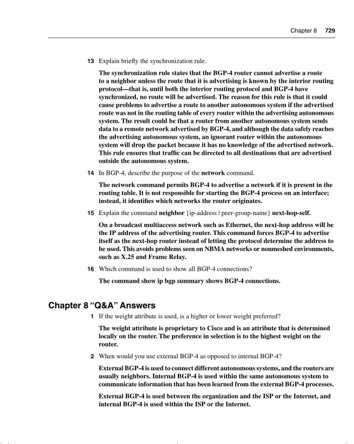
Chapter 8 729
13 Explain briefly the synchronization rule.
The synchronization rule states that the BGP-4 router cannot advertise a route to a neighbor unless the route that it is advertising is known by the interior routing protocol—that is, until both the interior routing protocol and BGP-4 have synchronized, no route will be advertised. The reason for this rule is that it could cause problems to advertise a route to another autonomous system if the advertised route was not in the routing table of every router within the advertising autonomous system. The result could be that a router from another autonomous system sends data to a remote network advertised by BGP-4, and although the data safely reaches the advertising autonomous system, an ignorant router within the autonomous system will drop the packet because it has no knowledge of the advertised network. This rule ensures that traffic can be directed to all destinations that are advertised outside the autonomous system.
14 In BGP-4, describe the purpose of the network command.
The network command permits BGP-4 to advertise a network if it is present in the routing table. It is not responsible for starting the BGP-4 process on an interface; instead, it identifies which networks the router originates.
15 Explain the command neighbor {ip-address | peer-group-name} next-hop-self.
On a broadcast multiaccess network such as Ethernet, the next-hop address will be the IP address of the advertising router. This command forces BGP-4 to advertise itself as the next-hop router instead of letting the protocol determine the address to be used. This avoids problems seen on NBMA networks or nonmeshed environments, such as X.25 and Frame Relay.
16 Which command is used to show all BGP-4 connections?
The command show ip bgp summary shows BGP-4 connections.
Chapter 8 “Q&A” Answers1 If the weight attribute is used, is a higher or lower weight preferred?
The weight attribute is proprietary to Cisco and is an attribute that is determined locally on the router. The preference in selection is to the highest weight on the router.
2 When would you use external BGP-4 as opposed to internal BGP-4?
External BGP-4 is used to connect different autonomous systems, and the routers are usually neighbors. Internal BGP-4 is used within the same autonomous system to communicate information that has been learned from the external BGP-4 processes.
External BGP-4 is used between the organization and the ISP or the Internet, and internal BGP-4 is used within the ISP or the Internet.
chpt_01.book Page 729 Thursday, December 21, 2000 6:22 PM
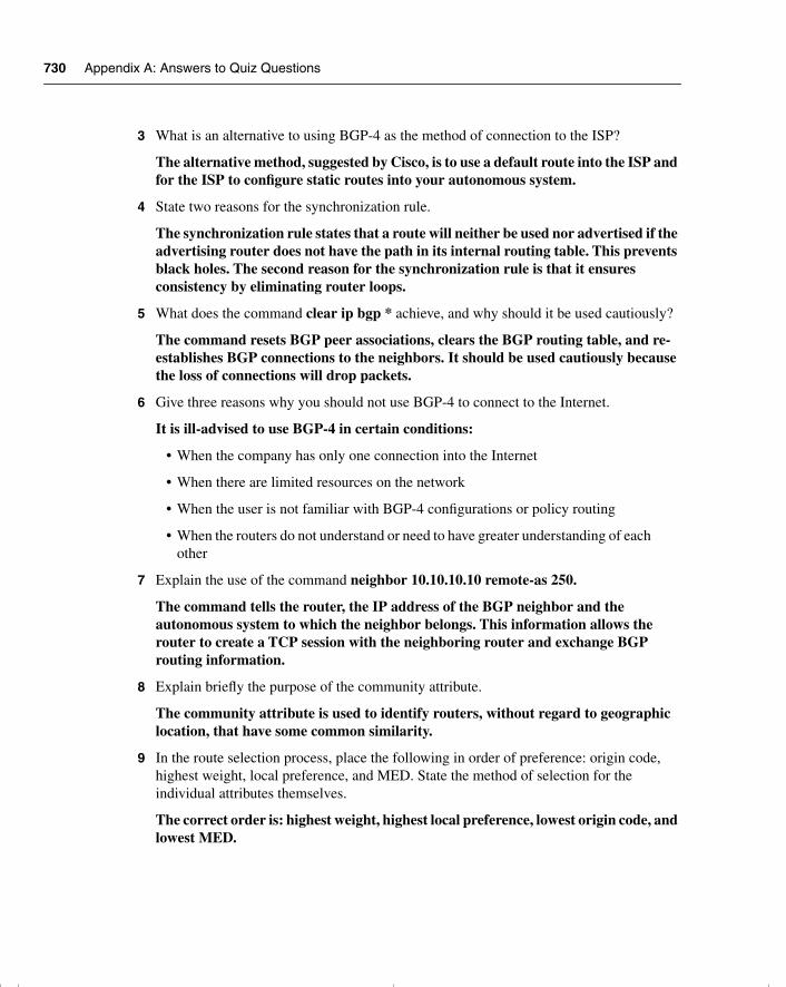
730 Appendix A: Answers to Quiz Questions
3 What is an alternative to using BGP-4 as the method of connection to the ISP?
The alternative method, suggested by Cisco, is to use a default route into the ISP and for the ISP to configure static routes into your autonomous system.
4 State two reasons for the synchronization rule.
The synchronization rule states that a route will neither be used nor advertised if the advertising router does not have the path in its internal routing table. This prevents black holes. The second reason for the synchronization rule is that it ensures consistency by eliminating router loops.
5 What does the command clear ip bgp * achieve, and why should it be used cautiously?
The command resets BGP peer associations, clears the BGP routing table, and re-establishes BGP connections to the neighbors. It should be used cautiously because the loss of connections will drop packets.
6 Give three reasons why you should not use BGP-4 to connect to the Internet.
It is ill-advised to use BGP-4 in certain conditions:
• When the company has only one connection into the Internet
• When there are limited resources on the network
• When the user is not familiar with BGP-4 configurations or policy routing
• When the routers do not understand or need to have greater understanding of each other
7 Explain the use of the command neighbor 10.10.10.10 remote-as 250.
The command tells the router, the IP address of the BGP neighbor and the autonomous system to which the neighbor belongs. This information allows the router to create a TCP session with the neighboring router and exchange BGP routing information.
8 Explain briefly the purpose of the community attribute.
The community attribute is used to identify routers, without regard to geographic location, that have some common similarity.
9 In the route selection process, place the following in order of preference: origin code, highest weight, local preference, and MED. State the method of selection for the individual attributes themselves.
The correct order is: highest weight, highest local preference, lowest origin code, and lowest MED.
chpt_01.book Page 730 Thursday, December 21, 2000 6:22 PM
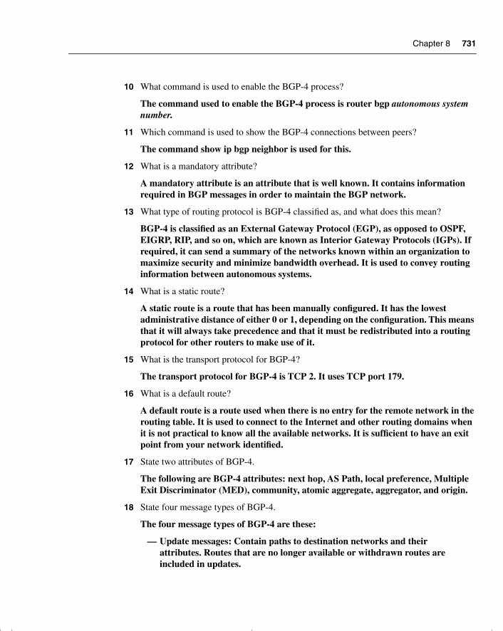
Chapter 8 731
10 What command is used to enable the BGP-4 process?
The command used to enable the BGP-4 process is router bgp autonomous system number.
11 Which command is used to show the BGP-4 connections between peers?
The command show ip bgp neighbor is used for this.
12 What is a mandatory attribute?
A mandatory attribute is an attribute that is well known. It contains information required in BGP messages in order to maintain the BGP network.
13 What type of routing protocol is BGP-4 classified as, and what does this mean?
BGP-4 is classified as an External Gateway Protocol (EGP), as opposed to OSPF, EIGRP, RIP, and so on, which are known as Interior Gateway Protocols (IGPs). If required, it can send a summary of the networks known within an organization to maximize security and minimize bandwidth overhead. It is used to convey routing information between autonomous systems.
14 What is a static route?
A static route is a route that has been manually configured. It has the lowest administrative distance of either 0 or 1, depending on the configuration. This means that it will always take precedence and that it must be redistributed into a routing protocol for other routers to make use of it.
15 What is the transport protocol for BGP-4?
The transport protocol for BGP-4 is TCP 2. It uses TCP port 179.
16 What is a default route?
A default route is a route used when there is no entry for the remote network in the routing table. It is used to connect to the Internet and other routing domains when it is not practical to know all the available networks. It is sufficient to have an exit point from your network identified.
17 State two attributes of BGP-4.
The following are BGP-4 attributes: next hop, AS Path, local preference, Multiple Exit Discriminator (MED), community, atomic aggregate, aggregator, and origin.
18 State four message types of BGP-4.
The four message types of BGP-4 are these:
— Update messages: Contain paths to destination networks and their attributes. Routes that are no longer available or withdrawn routes are included in updates.
chpt_01.book Page 731 Thursday, December 21, 2000 6:22 PM
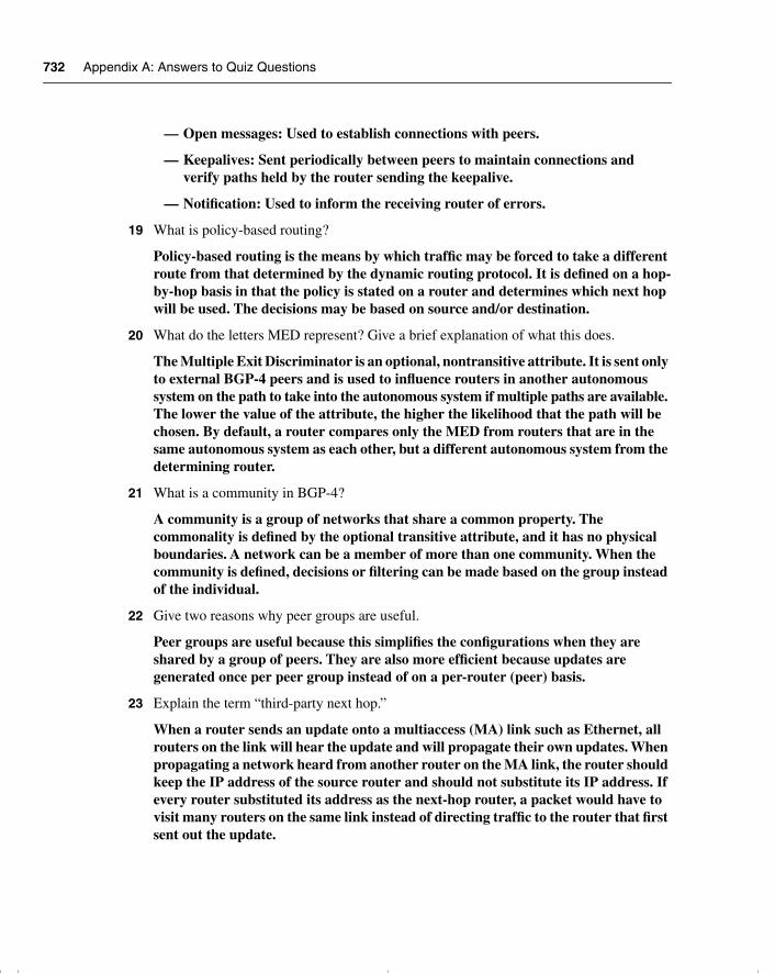
732 Appendix A: Answers to Quiz Questions
— Open messages: Used to establish connections with peers.
— Keepalives: Sent periodically between peers to maintain connections and verify paths held by the router sending the keepalive.
— Notification: Used to inform the receiving router of errors.
19 What is policy-based routing?
Policy-based routing is the means by which traffic may be forced to take a different route from that determined by the dynamic routing protocol. It is defined on a hop-by-hop basis in that the policy is stated on a router and determines which next hop will be used. The decisions may be based on source and/or destination.
20 What do the letters MED represent? Give a brief explanation of what this does.
The Multiple Exit Discriminator is an optional, nontransitive attribute. It is sent only to external BGP-4 peers and is used to influence routers in another autonomous system on the path to take into the autonomous system if multiple paths are available. The lower the value of the attribute, the higher the likelihood that the path will be chosen. By default, a router compares only the MED from routers that are in the same autonomous system as each other, but a different autonomous system from the determining router.
21 What is a community in BGP-4?
A community is a group of networks that share a common property. The commonality is defined by the optional transitive attribute, and it has no physical boundaries. A network can be a member of more than one community. When the community is defined, decisions or filtering can be made based on the group instead of the individual.
22 Give two reasons why peer groups are useful.
Peer groups are useful because this simplifies the configurations when they are shared by a group of peers. They are also more efficient because updates are generated once per peer group instead of on a per-router (peer) basis.
23 Explain the term “third-party next hop.”
When a router sends an update onto a multiaccess (MA) link such as Ethernet, all routers on the link will hear the update and will propagate their own updates. When propagating a network heard from another router on the MA link, the router should keep the IP address of the source router and should not substitute its IP address. If every router substituted its address as the next-hop router, a packet would have to visit many routers on the same link instead of directing traffic to the router that first sent out the update.
chpt_01.book Page 732 Thursday, December 21, 2000 6:22 PM
Chapter 8 733
24 What is the difference between a peer and a neighbor?
In external BGP-4, there is no difference between a neighbor and a peer. A peer is the BGP-4 term for a neighbor. Both terms refer to a router that is directly connected, with whom routing information is exchanged. In internal BGP-4 these routers are not necessarily physically adjacent, but they are the next logical hop router running the BGP-4.
25 Explain briefly the synchronization rule.
The synchronization rule states that the BGP-4 router cannot advertise a route to a neighbor unless the route that it is advertising is known by the interior routing pro-tocol—that is, until both the interior routing protocol and BGP-4 have synchronized, no route will be advertised. The reason for this rule is that it could cause problems to advertise a route to another autonomous system if the advertised route was not in the routing table of every router within the advertising autonomous system. The result could be that a router from another autonomous system sends data to a remote network advertised by BGP-4, and although the data safely reaches the advertising autonomous system, an ignorant router within the autonomous system will drop the packet because it has no knowledge of the advertised network. This rule ensures that traffic can be directed to all destinations that are advertised outside the autonomous system.
26 In BGP-4, describe the purpose of the network command.
The network command permits BGP-4 to advertise a network if it is present in the routing table. It is not responsible for starting the BGP-4 process on an interface; instead, it identifies which networks the router originates.
27 Explain the command neighbor {ip-address | peer-group-name} next-hop-self.
On a broadcast multiaccess network such as Ethernet, the next-hop address will be the IP address of the advertising router. This command forces BGP-4 to advertise itself as the next-hop router instead of letting the protocol determine the address to be used. This avoids problems seen on NBMA networks or nonmeshed environments, such as X.25 and Frame Relay.
28 Which command is used to show all BGP-4 connections?
The command show ip bgp summary shows BGP-4 connections.
chpt_01.book Page 733 Thursday, December 21, 2000 6:22 PM
734 Appendix A: Answers to Quiz Questions
Chapter 9
Chapter 9 “Do I Know This Already?” Quiz Answers1 Why does IBGP-4 need to be fully meshed?
IBGP-4 needs to be fully meshed because IBGP-4 has a fundamental rule that states that IBGP-4 will not propagate back into IBGP-4 a route that it has learned from IBGP-4. The reasoning is that this is the only way to prevent routing loops. If each router is connected to every other router (fully meshed), the updates come directly from the source, which removes the need for a router to propagate any updates that it has received.
2 How is a fully meshed network avoided in IBGP-4?
A fully meshed network can cause some problems to the routers because they have a great deal of information to deal with from every directly connected router. To avoid this intensity of bandwidth, CPU, and memory, an alternative is the configuration of route reflectors. Route reflectors allow the router to pass routes onto its peers.
3 What is the formula to determine the number of sessions needed in a fully meshed BGP-4 network?
The equation for determining the number of sessions required is n (n – 1) / 2, where n is the number of routers. Thus, 10 routers would mean 10 (10 – 1) / 2 = 10 × 9 / 2 = 45 sessions.
4 Why does a fully meshed network in IBGP-4 cause problems?
A fully meshed network in IBGP-4 causes problems because the network has to accommodate a large number of TCP connections, and this can eat up memory, CPU, and eventually bandwidth.
5 State two benefits to using route reflectors.
Route reflectors have many benefits:
— The use of a router reflector means that fewer TCP peer connections are needed. This streamlines the network traffic and solves the excessive use of network resources sometimes incurred with a fully meshed network.
— The design and configuration are very straightforward, which means that it is easy to implement and thus to migrate an existing network, particularly because path attributes are not affected by them.
chpt_01.book Page 734 Thursday, December 21, 2000 6:22 PM
Chapter 9 735
— Despite the fact that the route reflectors are straightforward, the flexibility in the design means that it is possible to become very sophisticated, using redundant route reflectors and even multiple levels of route reflectors. Complex solutions are possible using router reflectors.
6 Can the next-hop-self option be used between EBGP-4 peers?
No, the next-hop-self option is used only with IBGP-4. It is used on a broadcast multiaccess link and ensures that the appropriate source address for the update is provided in the message header. In EBGP-4, this is not relevant because the next hop is always that of the EBGP-4 neighbor.
7 Explain the difference between a cluster-ID and an originator-ID.
The cluster-ID is an optional, nontransitive BGP-4 attribute (type code 10). A cluster is the route reflector and its clients. If a cluster has more than one route reflector, it needs to be identified by a cluster-id. This is listed in the update; if a router receives an update with its own cluster-ID, it will be ignored, thus preventing routing loops. An originator-ID is the ID given to a route reflector when there is only one route reflector in the cluster. It serves the same purpose as the cluster-ID in that it prevents routing loops because a router that receives an update that contains its own originator-id will ignore the update. Therefore, the difference between the two is one of scale. The originator-ID is used for one route reflector in a cluster, whereas the cluster-ID is used when there are multiple route reflectors in the cluster.
8 State two advantages in using prefix lists over access lists.
The advantages of using prefix lists are the same as those of access lists. The advantages of using prefix lists instead of access lists include the following;
— They have better performance than access lists.
— They allow editing of the lists so that additional lines of code can be inserted anywhere in the list.
— The user interface is easier to use.
— They are more flexible.
9 If the ISP has provided a default route, how will the router within the autonomous system select the exit path in a multihomed environment?
The IGP within the autonomous system will use the metric associated with that routing protocol. The router running EIGRP, for example, will select the nearest router based on the composite metric of bandwidth and delay (by default).
chpt_01.book Page 735 Thursday, December 21, 2000 6:22 PM
736 Appendix A: Answers to Quiz Questions
10 What is a disadvantage of an autonomous system receiving full routing updates from all providers?
The disadvantage is that a great deal of network resources, such as memory and CPU, is required.
11 What is the danger of redistributing BGP-4 into the IGP?
The danger is that the autonomous system routers receiving the BGP-4 updates will be overwhelmed by the amount of routing information that they receive. This could result in an unstable network or even a network exhausted unto death.
12 What are the advantages of a fully meshed IBGP-4 network?
The advantage of a fully meshed network is that the network will receive full routing information from the directly connected peers. This means that the IGP does not need to carry routing information to the BGP-4 peers, and this means that no redistribution is necessary. This does not run the risk of overloading the IGP. It also means that the network will converge more quickly and that synchronization can be turned off, which will also improve performance.
13 In configuring a route reflector, how is the client configured?
The client of a route reflector is configured at the same time as the route reflector. The command issued on the router that is to become the route reflector identifies the router that is to become the client. The following command is the syntax issued at the router reflector:
neighbor ip address route-reflector-client
14 What command is used to display the route reflector clients?
The command show ip bgp neighbor is used.
15 What commands are used to display the BGP-4 router ID that identifies the router that is sending the updates and peering with its neighbor?
The commands that display the BGP-4 router ID are show ip bgp neighbor or show ip bgp ip address.
16 Which command is used to display the AS path?
The command used to display the AS path is show ip bgp.
Chapter 9 “Q&A” Answers1 If a route reflector hears an update from a nonclient, what action will be taken?
If a route reflector hears an update from a nonclient, it will reflect the update to clients only.
chpt_01.book Page 736 Thursday, December 21, 2000 6:22 PM
Chapter 9 737
2 In version 11.0 of the Cisco IOS, what method would be used to restrict routing information from being received or propagated?
Distribute lists would be used to restrict BGP-4 routing updates in version 11.0 of the Cisco IOS. Prefix lists became available to ISPs in 11.2 of the IOS and in 12.0 to the general public.
3 Explain the purpose and use of the command show ip prefix-list name [seq seq-number].
This command displays the entry prefix list with a given sequence number.
4 How and why would you redistribute static routes into BGP-4?
Static routes would be redistributed into BGP-4 with these commands:
router bgp 100redistribute staticip route 201.33.0.0 255.255.0.0 null 0
The static routes are forwarded to the nonexistent interface null 0 to aggregate the routes to create a supernet. This is then redistributed to the BGP process instead of the hundreds of routes that exist. Because any route redistributed into BGP-4 must be in the IP routing table, this is a way of creating a supernet and having it redistributed.
A static route to null 0 is not needed if the network command is used and no address aggregation is performed.
5 Give the command that would change the weight attribute for the path to the next hop 192.16.5.3.
The command to change the weight attribute for the path to the next hop to be 48 is as follows:
neighbor 192.16.5.3 weight 48
6 Why do route reflectors have to be fully meshed with IBGP-4?
Although clients are not fully meshed within a cluster, it is important that the route reflectors are fully meshed. This is to ensure that the routers pass routing information to each other. Remember that IBGP-4 does not propagate routing information; it generates information only based on the network command.
7 Why is filtering often required when redistributing BGP-4 into an IGP?
Filtering is often required when redistributing BGP-4 into an IGP because the routing tables can become overwhelmed by the number of routes that are imported.
8 What are the advantages of multihoming?
Multihoming allows for redundancy, which is important when the link is into the In-ternet and may well carry crucial business information for the company. Multihom-ing also increases performance by allowing the selection of the better paths.
chpt_01.book Page 737 Thursday, December 21, 2000 6:22 PM
738 Appendix A: Answers to Quiz Questions
9 What are the two most common forms of multihoming?
The most common forms of multihoming include these:
• The ISPs send default routes into the autonomous system.
• The default routes and some selected routes are sent by the ISP into the autonomous system.
• All routes known by the ISP are sent into the autonomous system.
10 Which command will show the local preference and weight attribute values?
The command that shows the local preference and weight attribute values is show ip bgp.
11 Why does IBGP-4 need to be fully meshed?
IBGP-4 needs to be fully meshed because IBGP-4 has a fundamental rule that states that IBGP-4 will not propagate back into IBGP-4 a route that it has learned from IBGP-4. The reasoning is that this is the only way to prevent routing loops. If each router is connected to every other router (fully meshed), the updates come directly from the source, which removes the need for a router to propagate any updates that it has received.
12 How is a fully meshed network avoided in IBGP-4?
A fully meshed network can cause some problems to the routers because they have a great deal of information to deal with from every directly connected router. To avoid this intensity of bandwidth, CPU, and memory, an alternative is the configuration of route reflectors. Route reflectors allow the router to pass routes on to its peers.
13 What is the formula to determine the number of sessions needed in a fully meshed BGP-4 network?
The equation for determining the number of sessions required is n (n – 1) / 2, where n is the number of routers. Thus, 10 routers would mean 10 (10 – 1) / 2 = 10 × 9 / 2 = 45 sessions.
14 Why does a fully meshed network in IBGP-4 cause problems?
A fully meshed network in IBGP-4 causes problems because the network has to accommodate a large number of TCP connections, and this can eat up memory, CPU, and eventually bandwidth.
15 State two benefits to using route reflectors.
Route reflectors have many benefits:
— The use of a router reflector means that fewer TCP peer connections are needed. This streamlines the network traffic and solves the excessive use of network resources sometimes incurred with a fully meshed network.
chpt_01.book Page 738 Thursday, December 21, 2000 6:22 PM
Chapter 9 739
— The design and configuration are very straightforward, which means that it is easy to implement and thus to migrate an existing network, particularly because path attributes are not affected by them.
— Despite the fact that the route reflectors are straightforward, the flexibility in the design means that it is possible to become very sophisticated using redundant route reflectors and even multiple levels of route reflectors. Complex solutions are possible using router reflectors.
16 Can the next-hop-self option be used between EBGP-4 peers?
No, the next-hop-self option is used only with IBGP-4. It is used on a broadcast multiaccess link and ensures that the appropriate source address for the update is provided in the message header. In EBGP-4, this is not relevant because the next hop is always that of the EBGP-4 neighbor.
17 Explain the difference between a cluster-ID and an originator-ID.
The cluster-ID is an optional, nontransitive BGP-4 attribute (type code 10). A cluster is the route reflector and its clients. If a cluster has more than one route reflector, it needs to be identified by a cluster-id. This is listed in the update; if a router receives an update with its own cluster-ID, it will be ignored, thus preventing routing loops. An originator-ID is the ID given to a route reflector when there is only one route reflector in the cluster. It serves the same purpose as the cluster-ID in that it prevents routing loops because a router that receives an update that contains its own originator-id will ignore the update. Therefore, the difference between the two is one of scale. The originator-ID is used for one route reflector in a cluster, whereas the cluster-ID is used when there are multiple route reflectors in the cluster.
18 State two advantages in using prefix lists over access lists.
The advantages of using prefix lists are the same as those of access lists. The advantages of using prefix lists instead of access lists include the following;
— They have a better performance than access lists.
— They allow editing of the lists so that additional lines of code can be inserted anywhere in the list.
— The user interface is easier to use.
— They are more flexible.
19 If the ISP has provided a default route, how will the router within the autonomous system select the exit path in a multihomed environment?
The IGP within the autonomous system will use the metric associated with that routing protocol. The router running EIGRP, for example, will select the nearest router based on the composite metric of bandwidth and delay (by default).
chpt_01.book Page 739 Thursday, December 21, 2000 6:22 PM
740 Appendix A: Answers to Quiz Questions
20 What is a disadvantage of an autonomous system receiving full routing updates from all providers?
The disadvantage is that a great deal of network resources, such as memory and CPU, is required.
21 What is the danger of redistributing BGP-4 into the IGP?
The danger is that the autonomous system routers receiving the BGP-4 updates will be overwhelmed by the amount of routing information that they receive. This could result in an unstable network or even a network exhausted unto death.
22 What are the advantages of a fully meshed IBGP-4 network?
The advantage of a fully meshed network is that the network will receive full routing information from the directly connected peers. This means that the IGP does not need to carry routing information to the BGP-4 peers, and this means that no redistribution is necessary. This does not run the risk of overloading the IGP. It also means that the network will converge more quickly and that synchronization can be turned off, which will also improve performance.
23 In configuring a route reflector, how is the client configured?
The client of a route reflector is configured at the same time as the route reflector. The command issued on the router that is to become the route reflector identifies the router that is to become the client. The following command is the syntax issued at the router reflector:
neighbor ip address route-reflector-client
24 What command is used to display the route reflector clients?
The show ip bgp neighbor command is used for this.
25 What commands are used to display the BGP-4 router ID that identifies the router that is sending the updates and peering with its neighbor?
The commands that display the BGP-4 router ID are show ip bgp neighbor or show ip bgp ip address.
26 Which command is used to display the AS path?
The command used to display the AS path is show ip bgp.
chpt_01.book Page 740 Thursday, December 21, 2000 6:22 PM
Chapter 10 741
Chapter 10
Chapter 10 “Do I Know This Already?” Quiz Answers1 Give two reasons for using multiple routing protocols.
The main reasons for multiple protocols existing within an organization are as follows:
— The organization is transitioning from one routing protocol to another because the network has grown and there is a need for a more sophisticated protocol that will scale.
— Although a vendor solution is preferred, there is a mix of different vendors within the network, so the vendor solution is used in the areas available. This is particularly true in client/server networks.
— Historically, the organization was a series of small network domains that have recently been tied together to form one large enterprise network. The company may well have plans to transition to a single routing protocol in the future.
— Often after a merger or a takeover, when several companies become one, it takes planning, strategy, and careful analysis to determine the best overall design for the network.
— Politically, there are ideological differences among the different network administrators, which until now have not been resolved.
— In a very large environment, the various domains may have different requirements, making a single solution inefficient. A clear example is in the case of a large multinational corporation, where EIGRP is the protocol used at the access and distribution layer, but BGP is the protocol connecting the core.
2 How many IP routing tables are there?
There is one IP routing table, and all the routes from all the different routing protocol are held in the one table. If a route has multiple paths from multiple protocols, one path will be selected based on the administrative distance.
3 When implementing redistribution, state one possible problem that you might experience, and explain why it is a problem.
The problems experienced as a result of multiple routing processes and their redistribution include the following:
— The wrong or less efficient routing decision being made, referred to as the suboptimal path.
chpt_01.book Page 741 Thursday, December 21, 2000 6:22 PM
742 Appendix A: Answers to Quiz Questions
— A routing loop occurring, where the data traffic is sent in a circle without ever arriving at the destination.
— The convergence time of the network increasing because of the different technologies involved. If the routing protocols converge at different rates, this may also cause problems. In some cases, this may result in timeouts and the temporary loss of networks.
4 Which has a lower administrative distance, IGRP or OSPF?
IGRP has an administrative distance of 100, while OSPF has an administrative distance of 110. The IGRP path will be entered into the routing table if there are paths offered to the same destination from both protocols.
5 What command is used to configure an outbound route filter?
The command for configuring a route filter is as follows:
distribute list {access-list-number | name} out[interface-name | routing process | autonomous-system number]
6 What is a passive interface?
A passive interface is an interface that will listen to routing updates but that will not propagate any updates for the protocol configured. It is used to prevent unnecessary traffic from being sent out of an interface. Usually a passive interface is configured when there are no routers to hear the updates on that network.
7 What is the purpose of administrative distance?
When the routing table is populated with networks that are provided by multiple routing protocols, the administrative distance is used to choose the best path to the remote network.
8 What is the concern of redistributing into a redundant network?
The concern with redistributing into a redundant network is that it is possible to select suboptimal routes. That is, if two routing protocols both have a path to the same destination, the path for the routing table will be selected based on administrative distance. This is a blanket solution that does not always render the best decision.
9 What is a default network?
A default network is a route used when there is no entry for the remote network in the routing table. It is used to connect to the Internet and other routing domains when it is not practical to know all the available networks. It is sufficient to have an exit point from your network identified.
chpt_01.book Page 742 Thursday, December 21, 2000 6:22 PM
Chapter 10 743
10 Why is it necessary to configure a default metric when redistributing between routing protocols?
The metric is used within a routing protocol to select the best path to a remote network when there are multiple paths. When redistributing, it is not always possible to port the metric across because the metric is protocol-specific. The default metric throws the original metric away and substitutes a new metric for the new routing protocol.
11 Which command is used to modify the administrative distance of a route?
The command to configure the administrative distance of a route is as follows:
distance weight [address mask [access-list-number | name]] [ip]
A different command is used for EIGRP and BGP-4. The EIGRP command to change the administrative distance is as follows:
distance eigrp internal-distance external-distance
12 What is the difference in processing for an inbound and an outbound route filter?
If a filter is applied to an incoming interface, the routing table is not checked unless the route is permitted. However, the router has to examine every incoming packet, which is expensive in resources. The outbound filter must go through the routing decision process the first time, after which the result is cached.
Inbound filters are wider-ranging because they prevent routes from entering the router instead of filtering on each outgoing interface that is affected.
13 State two benefits of using policy-based routing.
The benefits of policy-based routing include the following:
— Organizations can determine traffic flow based on the origin of the traffic. They can send traffic owned by different groups across different paths.
— Quality of service (QoS) can be set in the IP header using the precedence or TOS bits. This allows certain traffic to be prioritized through the network.
— High-cost links can be raised on more specific criteria, which allows an efficient use of the resources available.
— Traffic can be sent across multiple paths based on traffic characteristics.
14 How are matching routes modified in a route map?
Using the set commands modifies matching routes. If the criteria is met in the match command and the action was to permit, then the set criteria is initiated to control the routing as specified.
chpt_01.book Page 743 Thursday, December 21, 2000 6:22 PM
744 Appendix A: Answers to Quiz Questions
15 Explain the command set ip default-next-hop [ip-address...ip-address].
This command provides a list of IP addresses if there is no explicit route in the routing table for a destination. These addresses are those of next-hop routers or of the interfaces of adjacent routers. If multiple next-hop addresses are listed, then the first address is tried and the others are tried in turn.
16 Which command displays route maps that are configured on interfaces?
The command show ip policy displays the route maps used for policy routing on the router’s interfaces. The command show route-map [map-name] displays the route maps.
Chapter 10 “Q&A” Answers1 State two of the methods that Cisco recommends for controlling routing traffic.
The methods that Cisco discusses as useful methods of controlling routing updates are as follows:
— Passive interfaces: Prevent network communication and thus an adjacency from being formed with neighboring routers.
— Changing the administrative distance on the route: Changes the natural order as laid down by Cisco on which routing protocol is more plausible than the others. A scale of weighting is applied to the protocols.
— Default routes: Instruct the interface on where to send the destination traffic if the routing table had no entry for that destination.
— Static routes: Offers the ability to manually configure the path to a destination network.
— Route update filtering: Offers the use of access lists to configure.
2 What is the administrative distance for RIP?
The administrative distance for RIP is 120; it has the highest distance of interior routing protocols and is therefore the least likely to be selected.
3 State two instances when you do not want routing information propagated.
The two occasions that you do not want routing information to be propagated are as follows:
— If there is a WAN link where the cost of the link is based on network traffic. This may also have the added disincentive of being a WAN link that is a dial-on-demand link, which is raised and maintained by the presence of traffic attempting to flow across the interface.
chpt_01.book Page 744 Thursday, December 21, 2000 6:22 PM
Chapter 10 745
— The other situation in which you should prevent routing updates from being propagated is when you are trying to prevent routing loops. If the routing domain has redundant paths that will be learned by different routing protocol, it is advisable to filter the propagation of one of the paths.
4 In what instances will Enhanced IGRP automatically redistribute?
Enhanced IGRP will automatically redistribute between itself and IGRP as long as both processes are running the same autonomous system number.
Enhanced IGRP also automatically redistributes between the LAN protocol and Enhanced IGRP. EIGRP for IPX automatically redistributes; IPX for RIP/SAP and Enhanced IGRP for AppleTalk similarly redistribute automatically into RTMP.
5 Which command is used to view the administrative distance on a route?
The command show ip route displays the administrative distance for each route; the number is in brackets, coupled with the metric for the route.
6 When is redistribution required?
Redistribution is required when there is more than one routing protocol for IP running within the organization and when every part of the network needs connectivity to all the networks.
7 Why does Cisco recommend that you not overlap routing protocols?
The reason not to overlap routing protocols is that it will increase network traffic, router CPU processing, and memory because of the additional protocol updates. This additional traffic and CPU and memory requirements complicate the routing process. Now, the decision is not simply between multiple paths, but also between the various routing protocols that are advertising them.
8 Why would you want to prevent routing updates across an on-demand WAN link?
A WAN link that is a dial-on-demand link is raised and maintained by the presence of traffic attempting to flow across the interface. Thus, every time a RIP update was sent, the path would be raised—or, more likely, kept up all the time.
9 What is the metric used for in a routing protocol?
The metric is used to select the best path when multiple paths are available to a remote network.
10 Explain the command match ip-address {access-list-number | name} [access-list number | name].
The command is used to match criteria in establishing the policy-based routing. Access lists are used to specify the addressing of the packets to be affected.
chpt_01.book Page 745 Thursday, December 21, 2000 6:22 PM
746 Appendix A: Answers to Quiz Questions
11 Explain the command ip-route-cache policy.
This command is set on an incoming interface and enables the fast switching of policy routing. Before version 11.2 of the Cisco IOS, policy routing was process-switched. This caused some applications to time out, but the problem has now been resolved. Fast switching of policy routing is disabled by default. Therefore, it is necessary to manually configure it.
12 Give two reasons for using multiple routing protocols.
The main reasons for multiple protocols existing within an organization are as follows:
— The organization is transitioning from one routing protocol to another because the network has grown and there is a need for a more sophisticated protocol that will scale.
— Although a vendor solution is preferred, there is a mix of different vendors within the network, so the vendor solution is used in the areas available. This is particularly true in client/server networks.
— Historically, the organization was a series of small network domains that have recently been tied together to form one large enterprise network. The company may well have plans to transition to a single routing protocol in the future.
— Often after a merger or a takeover, when several companies become one, it takes planning, strategy, and careful analysis to determine the best overall design for the network.
— Politically, there are ideological differences among the different network administrators, which until now have not been resolved.
— In a very large environment, the various domains may have different requirements, making a single solution inefficient. A clear example is in the case of a large multinational corporation, where EIGRP is the protocol used at the access and distribution layer, but BGP is the protocol connecting the core.
13 How many IP routing tables are there?
There is one IP routing table, and all the routes from all the different routing protocol are held in the one table. If a route has multiple paths from multiple protocols, one path will be selected based on the administrative distance.
chpt_01.book Page 746 Thursday, December 21, 2000 6:22 PM
Chapter 10 747
14 When implementing redistribution, state one possible problem that you might experience, and explain why it is a problem.
The problems experienced as a result of multiple routing processes and their redistribution include the following:
— The wrong or a less efficient routing decision being made, referred to as the suboptimal path.
— A routing loop occurring, in which the data traffic is sent in a circle without ever arriving at the destination.
— The convergence time of the network increasing because of the different technologies involved. If the routing protocols converge at different rates, this may also cause problems. In some cases, this may result in timeouts and the temporary loss of networks.
15 Which has a lower administrative distance, IGRP or OSPF?
IGRP has an administrative distance of 100, while OSPF has an administrative distance of 110. The IGRP path will be entered into the routing table if there are paths offered to the same destination from both protocols.
16 What command is used to configure an outbound route filter?
The command for configuring a route filter is as follows:
distribute list {access-list-number | name} out[interface-name | routing process | autonomous-system number]
17 What is a passive interface?
A passive interface is an interface that will listen to routing updates but that will not propagate any updates for the protocol configured. It is used to prevent unnecessary traffic from being sent out of an interface. Usually a passive interface is configured when there are no routers to hear the updates on that network.
18 What is the purpose of administrative distance?
When the routing table is populated with networks that are provided by multiple routing protocols, the administrative distance is used to choose the best path to the remote network.
19 What is the concern of redistributing into a redundant network?
The concern with redistributing into a redundant network is that it is possible to select suboptimal routes. That is, if two routing protocols both have a path to the same destination, the path for the routing table will be selected based on administrative distance. This is a blanket solution that does not always render the best decision.
chpt_01.book Page 747 Thursday, December 21, 2000 6:22 PM
748 Appendix A: Answers to Quiz Questions
20 What is a default network?
A default network is a route used when there is no entry for the remote network in the routing table. It is used to connect to the Internet and other routing domains when it is not practical to know all the available networks. It is sufficient to have an exit point from your network identified.
21 Why is it necessary to configure a default metric when redistributing between routing protocols?
The metric is used within a routing protocol to select the best path to a remote network when there are multiple paths. When redistributing, it is not always possible to port the metric across because the metric is protocol-specific. The default metric throws the original metric away and substitutes a new metric for the new routing protocol.
22 Which command is used to modify the administrative distance of a route?
The command to configure the administrative distance of a route is as follows:
distance weight [address mask [access-list-number | name]] [ip]
A different command is used for EIGRP and BGP-4. The EIGRP command to change the administrative distance is as follows:
distance eigrp internal-distance external-distance
23 What is the difference in processing for an inbound and an outbound route filter?
If a filter is applied to an incoming interface, the routing table is not checked unless the route is permitted. However, the router has to examine every incoming packet, which is expensive in resources. The outbound filter must go through the routing decision process the first time, after which the result is cached.
Inbound filters are wider-ranging because they prevent routes from entering the router instead of filtering on each outgoing interface that is affected.
24 State two benefits of using policy-based routing.
The benefits of policy-based routing include the following:
— Organizations can determine traffic flow based on the origin of the traffic. They can send traffic owned by different groups across different paths.
— Quality of service (QoS) can be set in the IP header using the precedence or TOS bits. This allows certain traffic to be prioritized through the network.
— High-cost links can be raised on more specific criteria, which allows an efficient use of the resources available.
— Traffic can be send across multiple paths based on traffic characteristics.
chpt_01.book Page 748 Thursday, December 21, 2000 6:22 PM
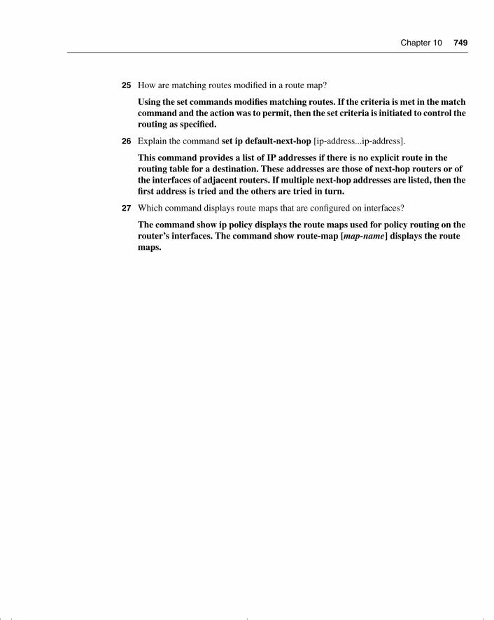
Chapter 10 749
25 How are matching routes modified in a route map?
Using the set commands modifies matching routes. If the criteria is met in the match command and the action was to permit, then the set criteria is initiated to control the routing as specified.
26 Explain the command set ip default-next-hop [ip-address...ip-address].
This command provides a list of IP addresses if there is no explicit route in the routing table for a destination. These addresses are those of next-hop routers or of the interfaces of adjacent routers. If multiple next-hop addresses are listed, then the first address is tried and the others are tried in turn.
27 Which command displays route maps that are configured on interfaces?
The command show ip policy displays the route maps used for policy routing on the router’s interfaces. The command show route-map [map-name] displays the route maps.
chpt_01.book Page 749 Thursday, December 21, 2000 6:22 PM

chpt_01.book Page 750 Thursday, December 21, 2000 6:22 PM
A P P E N D I X B
Sample Configurations
This appendix contains two live configurations taken from companies that are currently using them in their networks. (The names and addresses have been changed.) The comment sections of the configurations clarify major topics covered in this book and appear with a gray background.
This appendix is included because it can be very helpful to see the configuration of a particular topic in context, to see the wider picture that an entire configuration provides, and to dissect a real configuration that is up and running in a very large company.
chpt_01.book Page 751 Thursday, December 21, 2000 6:22 PM
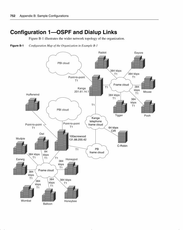
752 Appendix B: Sample Configurations
Configuration 1—OSPF and Dialup LinksFigure B-1 illustrates the wider network topology of the organization.
Figure B-1 Configuration Map of the Organization in Example B-1
PBI cloud
PBI cloud
Hufferwind
Point-to-pointT1
Point-to-pointT1
Point-to-pointT1
Owl
Mudpie
84kbpsT1
384 kbpsT1
384 kbpsT1 384 kbps
T1
384 kbpsT1
384 kbpsT1
384kbpsT1
384kbpsT1
384kbpsT1
384kbpsT1
384kbpsT1
384kbpsT1
T1
T1
T1
T1
Earwig Honeypot
WombatBalloon
Honeybee
Frame cloud
Frame cloud
PBframe cloud
Kangatelephone
frame cloud
100acrewood131.88.200.42
64 kbpsCIR
C-Robin
Kanga201.61.14.1
Rabbit Eeyore
Mouse
PoohTigger
chpt_01.book Page 752 Thursday, December 21, 2000 6:22 PM
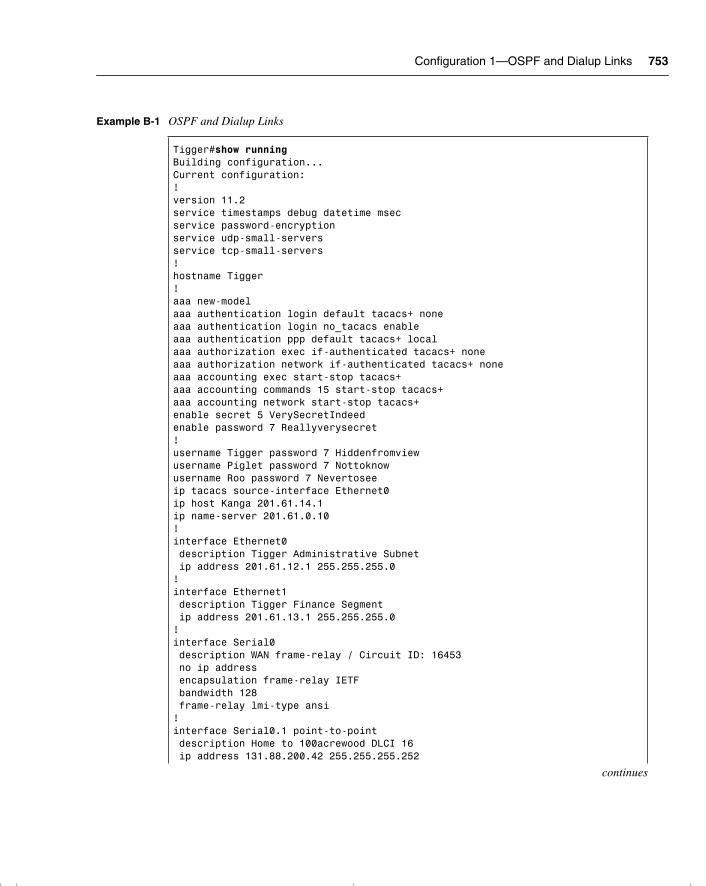
Configuration 1—OSPF and Dialup Links 753
Example B-1 OSPF and Dialup Links
Tigger#show runningBuilding configuration...Current configuration:!version 11.2service timestamps debug datetime msecservice password-encryptionservice udp-small-serversservice tcp-small-servers!hostname Tigger!aaa new-modelaaa authentication login default tacacs+ noneaaa authentication login no_tacacs enableaaa authentication ppp default tacacs+ localaaa authorization exec if-authenticated tacacs+ noneaaa authorization network if-authenticated tacacs+ noneaaa accounting exec start-stop tacacs+aaa accounting commands 15 start-stop tacacs+aaa accounting network start-stop tacacs+enable secret 5 VerySecretIndeedenable password 7 Reallyverysecret!username Tigger password 7 Hiddenfromviewusername Piglet password 7 Nottoknowusername Roo password 7 Nevertoseeip tacacs source-interface Ethernet0ip host Kanga 201.61.14.1ip name-server 201.61.0.10!interface Ethernet0 description Tigger Administrative Subnet ip address 201.61.12.1 255.255.255.0!interface Ethernet1 description Tigger Finance Segment ip address 201.61.13.1 255.255.255.0!interface Serial0 description WAN frame-relay / Circuit ID: 16453 no ip address encapsulation frame-relay IETF bandwidth 128 frame-relay lmi-type ansi!interface Serial0.1 point-to-point description Home to 100acrewood DLCI 16 ip address 131.88.200.42 255.255.255.252
continues
chpt_01.book Page 753 Thursday, December 21, 2000 6:22 PM
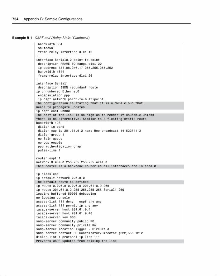
754 Appendix B: Sample Configurations
bandwidth 384 shutdown frame-relay interface-dlci 16!interface Serial0.2 point-to-point description FRAME TO Kanga dlci 20 ip address 131.88.240.17 255.255.255.252 bandwidth 1544 frame-relay interface-dlci 20!interface Serial1 description ISDN redundant routeip unnumbered Ethernet0 encapsulation ppp ip ospf network point-to-multipointThe configuration is stating that it is a NMBA cloud thatneeds to propagate updatesip ospf cost 20000The cost of the link is so high as to render it unusable unlessthere is no alternative. Similar to a floating static routebandwidth 128 dialer in-band dialer map ip 201.61.0.2 name Roo broadcast 14152274113 dialer-group 1 no fair-queue no cdp enable ppp authentication chap pulse-time 1!router ospf 1network 0.0.0.0 255.255.255.255 area 0This router is a backbone router as all interfaces are in area 0!ip classlessip default-network 0.0.0.0The default route is definedip route 0.0.0.0 0.0.0.0 201.61.0.2 200ip route 201.61.0.2 255.255.255.255 Serial1 200logging buffered 50000 debuggingno logging consoleaccess-list 111 deny ospf any anyaccess-list 111 permit ip any anytacacs-server host 201.61.0.4tacacs-server host 201.61.0.40tacacs-server key 666snmp-server community public ROsnmp-server community private RWsnmp-server location Tigger - Circuit #snmp-server contact PC Coordinator/Director (222)555-1212dialer-list 1 protocol ip list 111Prevents OSPF updates from raising the line
Example B-1 OSPF and Dialup Links (Continued)
chpt_01.book Page 754 Thursday, December 21, 2000 6:22 PM
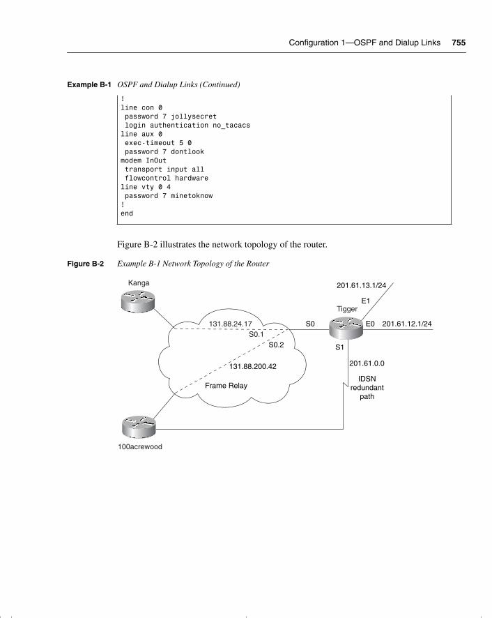
Configuration 1—OSPF and Dialup Links 755
Figure B-2 illustrates the network topology of the router.
Figure B-2 Example B-1 Network Topology of the Router
!line con 0 password 7 jollysecret login authentication no_tacacsline aux 0 exec-timeout 5 0 password 7 dontlookmodem InOut transport input all flowcontrol hardwareline vty 0 4 password 7 minetoknow!end
Example B-1 OSPF and Dialup Links (Continued)
131.88.24.17
S0.2
Frame Relay
131.88.200.42
Kanga
100acrewood
Tigger
S0
E1
E0
S1
201.61.12.1/24
201.61.0.0
S0.1
201.61.13.1/24
IDSNredundant
path
chpt_01.book Page 755 Thursday, December 21, 2000 6:22 PM
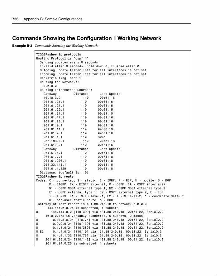
756 Appendix B: Sample Configurations
Commands Showing the Configuration 1 Working NetworkExample B-2 Commands Showing the Working Network
TIGGER#show ip protocolsRouting Protocol is "ospf 1" Sending updates every 0 seconds Invalid after 0 seconds, hold down 0, flushed after 0 Outgoing update filter list for all interfaces is not set Incoming update filter list for all interfaces is not set Redistributing: ospf 1 Routing for Networks: 0.0.0.0 Routing Information Sources: Gateway Distance Last Update 10.10.3.2 110 00:01:15 201.61.25.1 110 00:01:15 201.61.27.1 110 00:01:15 201.61.29.1 110 00:01:15 201.61.31.1 110 00:01:15 201.61.17.1 110 00:01:16 201.61.23.1 110 00:01:16 201.61.9.1 110 00:01:16 201.61.11.1 110 00:00:19 201.61.0.1 110 00:01:16 201.61.1.1 110 3w0d 207.183.0.1 110 00:01:16 201.61.3.1 110 00:01:16 Gateway Distance Last Update 201.61.5.1 110 00:01:18 201.61.7.1 110 00:01:18 201.61.200.1 110 00:01:18 201.33.143.1 110 00:01:18 201.61.1.129 110 00:01:18 Distance: (default is 110)TIGGER#show ip routeCodes: C - connected, S - static, I - IGRP, R - RIP, M - mobile, B - BGP D - EIGRP, EX - EIGRP external, O - OSPF, IA - OSPF inter area N1 - OSPF NSSA external type 1, N2 - OSPF NSSA external type 2 E1 - OSPF external type 1, E2 - OSPF external type 2, E - EGP i - IS-IS, L1 - IS-IS level-1, L2 - IS-IS level-2, * - candidate default U - per-user static route, o - ODR Gateway of last resort is 131.88.240.18 to network 0.0.0.0 144.144.0.0/24 is subnetted, 1 subnetsO 144.144.0.0 [110/399] via 131.88.240.18, 00:01:22, Serial0.2 10.0.0.0/8 is variably subnetted, 5 subnets, 2 masksO 10.10.3.0/24 [110/74] via 131.88.240.18, 00:01:22, Serial0.2O 10.9.9.0/24 [110/139] via 131.88.240.18, 00:01:22, Serial0.2O 10.1.1.0/24 [110/389] via 131.88.240.18, 00:01:22, Serial0.2O E2 10.4.4.0/24 [110/10] via 131.88.240.18, 00:01:22, Serial0.2O 10.4.4.1/32 [110/75] via 131.88.240.18, 00:01:22, Serial0.2O 201.61.25.0/24 [110/142] via 131.88.240.18, 00:01:22, Serial0.2 201.61.24.0/26 is subnetted, 1 subnets
chpt_01.book Page 756 Thursday, December 21, 2000 6:22 PM
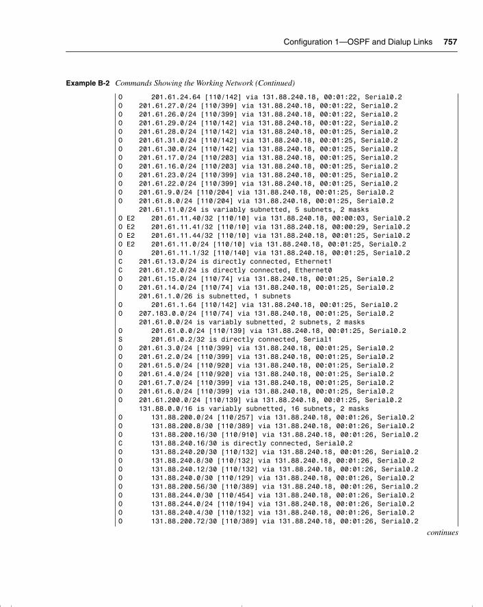
Configuration 1—OSPF and Dialup Links 757
O 201.61.24.64 [110/142] via 131.88.240.18, 00:01:22, Serial0.2O 201.61.27.0/24 [110/399] via 131.88.240.18, 00:01:22, Serial0.2O 201.61.26.0/24 [110/399] via 131.88.240.18, 00:01:22, Serial0.2O 201.61.29.0/24 [110/142] via 131.88.240.18, 00:01:22, Serial0.2O 201.61.28.0/24 [110/142] via 131.88.240.18, 00:01:25, Serial0.2O 201.61.31.0/24 [110/142] via 131.88.240.18, 00:01:25, Serial0.2O 201.61.30.0/24 [110/142] via 131.88.240.18, 00:01:25, Serial0.2O 201.61.17.0/24 [110/203] via 131.88.240.18, 00:01:25, Serial0.2O 201.61.16.0/24 [110/203] via 131.88.240.18, 00:01:25, Serial0.2O 201.61.23.0/24 [110/399] via 131.88.240.18, 00:01:25, Serial0.2O 201.61.22.0/24 [110/399] via 131.88.240.18, 00:01:25, Serial0.2O 201.61.9.0/24 [110/204] via 131.88.240.18, 00:01:25, Serial0.2O 201.61.8.0/24 [110/204] via 131.88.240.18, 00:01:25, Serial0.2 201.61.11.0/24 is variably subnetted, 5 subnets, 2 masksO E2 201.61.11.40/32 [110/10] via 131.88.240.18, 00:00:03, Serial0.2O E2 201.61.11.41/32 [110/10] via 131.88.240.18, 00:00:29, Serial0.2O E2 201.61.11.44/32 [110/10] via 131.88.240.18, 00:01:25, Serial0.2O E2 201.61.11.0/24 [110/10] via 131.88.240.18, 00:01:25, Serial0.2O 201.61.11.1/32 [110/140] via 131.88.240.18, 00:01:25, Serial0.2C 201.61.13.0/24 is directly connected, Ethernet1C 201.61.12.0/24 is directly connected, Ethernet0O 201.61.15.0/24 [110/74] via 131.88.240.18, 00:01:25, Serial0.2O 201.61.14.0/24 [110/74] via 131.88.240.18, 00:01:25, Serial0.2 201.61.1.0/26 is subnetted, 1 subnetsO 201.61.1.64 [110/142] via 131.88.240.18, 00:01:25, Serial0.2O 207.183.0.0/24 [110/74] via 131.88.240.18, 00:01:25, Serial0.2 201.61.0.0/24 is variably subnetted, 2 subnets, 2 masksO 201.61.0.0/24 [110/139] via 131.88.240.18, 00:01:25, Serial0.2S 201.61.0.2/32 is directly connected, Serial1O 201.61.3.0/24 [110/399] via 131.88.240.18, 00:01:25, Serial0.2O 201.61.2.0/24 [110/399] via 131.88.240.18, 00:01:25, Serial0.2O 201.61.5.0/24 [110/920] via 131.88.240.18, 00:01:25, Serial0.2O 201.61.4.0/24 [110/920] via 131.88.240.18, 00:01:25, Serial0.2O 201.61.7.0/24 [110/399] via 131.88.240.18, 00:01:25, Serial0.2O 201.61.6.0/24 [110/399] via 131.88.240.18, 00:01:25, Serial0.2O 201.61.200.0/24 [110/139] via 131.88.240.18, 00:01:25, Serial0.2 131.88.0.0/16 is variably subnetted, 16 subnets, 2 masksO 131.88.200.0/24 [110/257] via 131.88.240.18, 00:01:26, Serial0.2O 131.88.200.8/30 [110/389] via 131.88.240.18, 00:01:26, Serial0.2O 131.88.200.16/30 [110/910] via 131.88.240.18, 00:01:26, Serial0.2C 131.88.240.16/30 is directly connected, Serial0.2O 131.88.240.20/30 [110/132] via 131.88.240.18, 00:01:26, Serial0.2O 131.88.240.8/30 [110/132] via 131.88.240.18, 00:01:26, Serial0.2O 131.88.240.12/30 [110/132] via 131.88.240.18, 00:01:26, Serial0.2O 131.88.240.0/30 [110/129] via 131.88.240.18, 00:01:26, Serial0.2O 131.88.200.56/30 [110/389] via 131.88.240.18, 00:01:26, Serial0.2O 131.88.244.0/30 [110/454] via 131.88.240.18, 00:01:26, Serial0.2O 131.88.244.0/24 [110/194] via 131.88.240.18, 00:01:26, Serial0.2O 131.88.240.4/30 [110/132] via 131.88.240.18, 00:01:26, Serial0.2O 131.88.200.72/30 [110/389] via 131.88.240.18, 00:01:26, Serial0.2
continues
Example B-2 Commands Showing the Working Network (Continued)
chpt_01.book Page 757 Thursday, December 21, 2000 6:22 PM
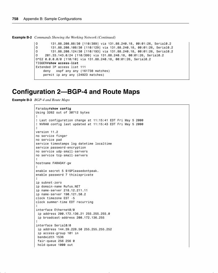
758 Appendix B: Sample Configurations
Configuration 2—BGP-4 and Route Maps
O 131.88.200.88/30 [110/389] via 131.88.240.18, 00:01:26, Serial0.2O 131.88.200.108/30 [110/129] via 131.88.240.18, 00:01:26, Serial0.2O 131.88.200.124/30 [110/193] via 131.88.240.18, 00:01:26, Serial0.2O 201.33.143.0/24 [110/399] via 131.88.240.18, 00:01:26, Serial0.2O*E2 0.0.0.0/0 [110/10] via 131.88.240.18, 00:01:26, Serial0.2TIGGER#show access-listExtended IP access list 111 deny ospf any any (161738 matches) permit ip any any (24923 matches)
Example B-3 BGP-4 and Route Maps
Faraday#show configUsing 3262 out of 30712 bytes!! Last configuration change at 11:15:41 EDT Fri May 5 2000! NVRAM config last updated at 11:15:43 EDT Fri May 5 2000!version 11.2no service fingerno service padservice timestamps log datetime localtimeservice password-encryptionno service udp-small-serversno service tcp-small-servers!hostname FARADAY-gw!enable secret 5 $1$Pleasedontpeak.enable password 7 thisisprivate!ip subnet-zeroip domain-name Rufus.NETip name-server 218.12.211.11ip name-server 190.121.50.2clock timezone EST -5clock summer-time EDT recurring!interface Ethernet0/0 ip address 200.172.136.21 255.255.255.0 ip broadcast-address 200.172.136.255!interface Serial0/0 ip address 144.39.228.50 255.255.255.252 ip access-group 101 in bandwidth 1536 fair-queue 256 256 0 hold-queue 1000 out
Example B-2 Commands Showing the Working Network (Continued)
chpt_01.book Page 758 Thursday, December 21, 2000 6:22 PM
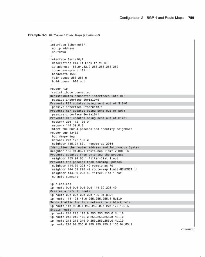
Configuration 2—BGP-4 and Route Maps 759
!interface Ethernet0/1 no ip address shutdown!interface Serial0/1 description ### T1 Link to VERDI ip address 155.94.83.2 255.255.255.252 ip access-group 101 in bandwidth 1536 fair-queue 256 256 0 hold-queue 1000 out!router rip redistribute connectedRedistributes connected interfaces into RIP passive-interface Serial0/0Prevents RIP updates being sent out of S10/0 passive-interface Ethernet0/1Prevents RIP updates being sent out of E0/1 passive-interface Serial0/1Prevents RIP updates being sent out of S10/1 network 200.172.136.0 network 144.39.0.0!Start the BGP-4 process and identify neighborsrouter bgp 13462 bgp dampening network 200.172.136.0 neighbor 155.94.83.1 remote-as 2914Identifies the router address and Autonomous System neighbor 155.94.83.1 route-map limit-VERDI inPrevents updates from entering the process neighbor 155.94.83.1 filter-list 1 outPrevents the process from sending updates neighbor 144.39.228.49 remote-as 701 neighbor 144.39.228.49 route-map limit-MEMENET in neighbor 144.39.228.49 filter-list 1 out no auto-summary!ip classlessip route 0.0.0.0 0.0.0.0 144.39.228.49Creates a default routeip route 0.0.0.0 0.0.0.0 155.94.83.1ip route 111.193.48.0 255.255.255.0 Null0Sends traffic for this network to a black holeip route 140.98.0.0 255.255.0.0 200.172.136.5Static routeip route 218.215.175.0 255.255.255.0 Null0ip route 218.215.176.0 255.255.255.0 Null0ip route 218.215.249.0 255.255.255.0 Null0ip route 220.99.235.0 255.255.255.0 155.94.83.1
continues
Example B-3 BGP-4 and Route Maps (Continued)
chpt_01.book Page 759 Thursday, December 21, 2000 6:22 PM
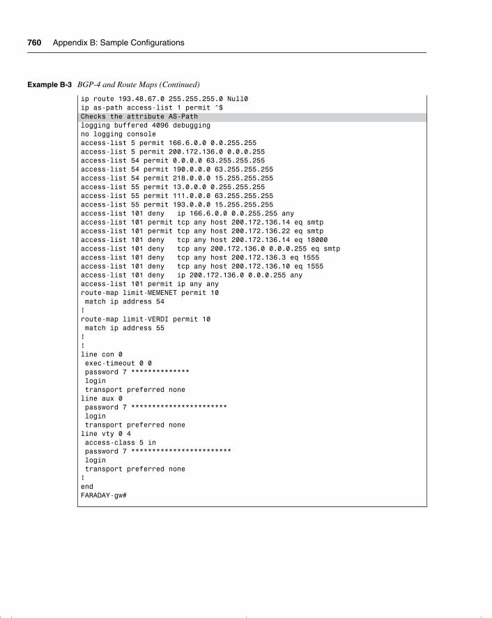
760 Appendix B: Sample Configurations
ip route 193.48.67.0 255.255.255.0 Null0ip as-path access-list 1 permit ^$Checks the attribute AS-Pathlogging buffered 4096 debuggingno logging consoleaccess-list 5 permit 166.6.0.0 0.0.255.255access-list 5 permit 200.172.136.0 0.0.0.255access-list 54 permit 0.0.0.0 63.255.255.255access-list 54 permit 190.0.0.0 63.255.255.255access-list 54 permit 218.0.0.0 15.255.255.255access-list 55 permit 13.0.0.0 0.255.255.255access-list 55 permit 111.0.0.0 63.255.255.255access-list 55 permit 193.0.0.0 15.255.255.255access-list 101 deny ip 166.6.0.0 0.0.255.255 anyaccess-list 101 permit tcp any host 200.172.136.14 eq smtpaccess-list 101 permit tcp any host 200.172.136.22 eq smtpaccess-list 101 deny tcp any host 200.172.136.14 eq 18000access-list 101 deny tcp any 200.172.136.0 0.0.0.255 eq smtpaccess-list 101 deny tcp any host 200.172.136.3 eq 1555access-list 101 deny tcp any host 200.172.136.10 eq 1555access-list 101 deny ip 200.172.136.0 0.0.0.255 anyaccess-list 101 permit ip any anyroute-map limit-MEMENET permit 10 match ip address 54!route-map limit-VERDI permit 10 match ip address 55!!line con 0 exec-timeout 0 0 password 7 ************** login transport preferred noneline aux 0 password 7 *********************** login transport preferred noneline vty 0 4 access-class 5 in password 7 ************************ login transport preferred none!endFARADAY-gw#
Example B-3 BGP-4 and Route Maps (Continued)
chpt_01.book Page 760 Thursday, December 21, 2000 6:22 PM
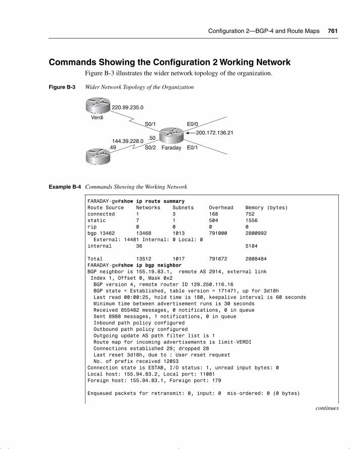
Configuration 2—BGP-4 and Route Maps 761
Commands Showing the Configuration 2 Working NetworkFigure B-3 illustrates the wider network topology of the organization.
Figure B-3 Wider Network Topology of the Organization
Example B-4 Commands Showing the Working Network
FARADAY-gw#show ip route summaryRoute Source Networks Subnets Overhead Memory (bytes)connected 1 3 168 752static 7 1 504 1556rip 0 0 0 0bgp 13462 13468 1013 791000 2800992 External: 14481 Internal: 0 Local: 0internal 36 5184
Total 13512 1017 791672 2808484FARADAY-gw#show ip bgp neighborBGP neighbor is 155.19.83.1, remote AS 2914, external link Index 1, Offset 0, Mask 0x2 BGP version 4, remote router ID 129.250.116.16 BGP state = Established, table version = 171471, up for 3d18h Last read 00:00:25, hold time is 180, keepalive interval is 60 seconds Minimum time between advertisement runs is 30 seconds Received 855482 messages, 0 notifications, 0 in queue Sent 8988 messages, 1 notifications, 0 in queue Inbound path policy configured Outbound path policy configured Outgoing update AS path filter list is 1 Route map for incoming advertisements is limit-VERDI Connections established 29; dropped 28 Last reset 3d18h, due to : User reset request No. of prefix received 12053Connection state is ESTAB, I/O status: 1, unread input bytes: 0Local host: 155.94.83.2, Local port: 11081Foreign host: 155.94.83.1, Foreign port: 179
Enqueued packets for retransmit: 0, input: 0 mis-ordered: 0 (0 bytes)
continues
S0/1
S0/2
E0/0
E0/1
.50
.49144.39.228.0
220.99.235.0
Verdi
Faraday
200.172.136.21
chpt_01.book Page 761 Thursday, December 21, 2000 6:22 PM
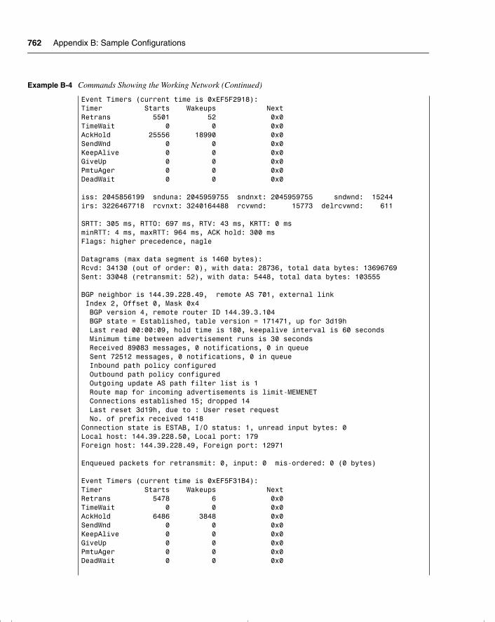
762 Appendix B: Sample Configurations
Event Timers (current time is 0xEF5F2918):Timer Starts Wakeups NextRetrans 5501 52 0x0TimeWait 0 0 0x0AckHold 25556 18990 0x0SendWnd 0 0 0x0KeepAlive 0 0 0x0GiveUp 0 0 0x0PmtuAger 0 0 0x0DeadWait 0 0 0x0
iss: 2045856199 snduna: 2045959755 sndnxt: 2045959755 sndwnd: 15244irs: 3226467718 rcvnxt: 3240164488 rcvwnd: 15773 delrcvwnd: 611
SRTT: 305 ms, RTTO: 697 ms, RTV: 43 ms, KRTT: 0 msminRTT: 4 ms, maxRTT: 964 ms, ACK hold: 300 msFlags: higher precedence, nagle
Datagrams (max data segment is 1460 bytes):Rcvd: 34130 (out of order: 0), with data: 28736, total data bytes: 13696769Sent: 33048 (retransmit: 52), with data: 5448, total data bytes: 103555
BGP neighbor is 144.39.228.49, remote AS 701, external link Index 2, Offset 0, Mask 0x4 BGP version 4, remote router ID 144.39.3.104 BGP state = Established, table version = 171471, up for 3d19h Last read 00:00:09, hold time is 180, keepalive interval is 60 seconds Minimum time between advertisement runs is 30 seconds Received 89083 messages, 0 notifications, 0 in queue Sent 72512 messages, 0 notifications, 0 in queue Inbound path policy configured Outbound path policy configured Outgoing update AS path filter list is 1 Route map for incoming advertisements is limit-MEMENET Connections established 15; dropped 14 Last reset 3d19h, due to : User reset request No. of prefix received 1418Connection state is ESTAB, I/O status: 1, unread input bytes: 0Local host: 144.39.228.50, Local port: 179Foreign host: 144.39.228.49, Foreign port: 12971
Enqueued packets for retransmit: 0, input: 0 mis-ordered: 0 (0 bytes)
Event Timers (current time is 0xEF5F31B4):Timer Starts Wakeups NextRetrans 5478 6 0x0TimeWait 0 0 0x0AckHold 6486 3848 0x0SendWnd 0 0 0x0KeepAlive 0 0 0x0GiveUp 0 0 0x0PmtuAger 0 0 0x0DeadWait 0 0 0x0
Example B-4 Commands Showing the Working Network (Continued)
chpt_01.book Page 762 Thursday, December 21, 2000 6:22 PM
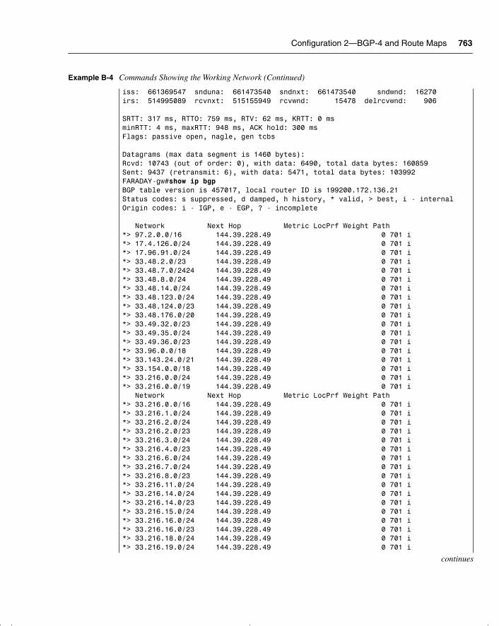
Configuration 2—BGP-4 and Route Maps 763
iss: 661369547 snduna: 661473540 sndnxt: 661473540 sndwnd: 16270irs: 514995089 rcvnxt: 515155949 rcvwnd: 15478 delrcvwnd: 906
SRTT: 317 ms, RTTO: 759 ms, RTV: 62 ms, KRTT: 0 msminRTT: 4 ms, maxRTT: 948 ms, ACK hold: 300 msFlags: passive open, nagle, gen tcbs
Datagrams (max data segment is 1460 bytes):Rcvd: 10743 (out of order: 0), with data: 6490, total data bytes: 160859Sent: 9437 (retransmit: 6), with data: 5471, total data bytes: 103992FARADAY-gw#show ip bgpBGP table version is 457017, local router ID is 199200.172.136.21Status codes: s suppressed, d damped, h history, * valid, > best, i - internalOrigin codes: i - IGP, e - EGP, ? - incomplete
Network Next Hop Metric LocPrf Weight Path*> 97.2.0.0/16 144.39.228.49 0 701 i*> 17.4.126.0/24 144.39.228.49 0 701 i*> 17.96.91.0/24 144.39.228.49 0 701 i*> 33.48.2.0/23 144.39.228.49 0 701 i*> 33.48.7.0/2424 144.39.228.49 0 701 i*> 33.48.8.0/24 144.39.228.49 0 701 i*> 33.48.14.0/24 144.39.228.49 0 701 i*> 33.48.123.0/24 144.39.228.49 0 701 i*> 33.48.124.0/23 144.39.228.49 0 701 i*> 33.48.176.0/20 144.39.228.49 0 701 i*> 33.49.32.0/23 144.39.228.49 0 701 i*> 33.49.35.0/24 144.39.228.49 0 701 i*> 33.49.36.0/23 144.39.228.49 0 701 i*> 33.96.0.0/18 144.39.228.49 0 701 i*> 33.143.24.0/21 144.39.228.49 0 701 i*> 33.154.0.0/18 144.39.228.49 0 701 i*> 33.216.0.0/24 144.39.228.49 0 701 i*> 33.216.0.0/19 144.39.228.49 0 701 i Network Next Hop Metric LocPrf Weight Path*> 33.216.0.0/16 144.39.228.49 0 701 i*> 33.216.1.0/24 144.39.228.49 0 701 i*> 33.216.2.0/24 144.39.228.49 0 701 i*> 33.216.2.0/23 144.39.228.49 0 701 i*> 33.216.3.0/24 144.39.228.49 0 701 i*> 33.216.4.0/23 144.39.228.49 0 701 i*> 33.216.6.0/24 144.39.228.49 0 701 i*> 33.216.7.0/24 144.39.228.49 0 701 i*> 33.216.8.0/23 144.39.228.49 0 701 i*> 33.216.11.0/24 144.39.228.49 0 701 i*> 33.216.14.0/24 144.39.228.49 0 701 i*> 33.216.14.0/23 144.39.228.49 0 701 i*> 33.216.15.0/24 144.39.228.49 0 701 i*> 33.216.16.0/24 144.39.228.49 0 701 i*> 33.216.16.0/23 144.39.228.49 0 701 i*> 33.216.18.0/24 144.39.228.49 0 701 i*> 33.216.19.0/24 144.39.228.49 0 701 i
continues
Example B-4 Commands Showing the Working Network (Continued)
chpt_01.book Page 763 Thursday, December 21, 2000 6:22 PM
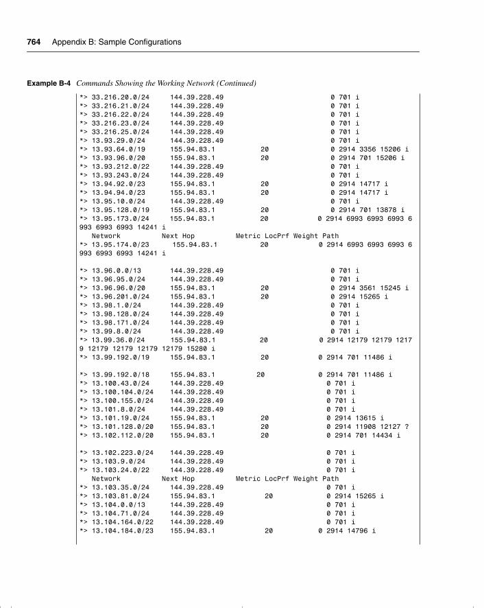
764 Appendix B: Sample Configurations
*> 33.216.20.0/24 144.39.228.49 0 701 i*> 33.216.21.0/24 144.39.228.49 0 701 i*> 33.216.22.0/24 144.39.228.49 0 701 i*> 33.216.23.0/24 144.39.228.49 0 701 i*> 33.216.25.0/24 144.39.228.49 0 701 i*> 13.93.29.0/24 144.39.228.49 0 701 i*> 13.93.64.0/19 155.94.83.1 20 0 2914 3356 15206 i*> 13.93.96.0/20 155.94.83.1 20 0 2914 701 15206 i*> 13.93.212.0/22 144.39.228.49 0 701 i*> 13.93.243.0/24 144.39.228.49 0 701 i*> 13.94.92.0/23 155.94.83.1 20 0 2914 14717 i*> 13.94.94.0/23 155.94.83.1 20 0 2914 14717 i*> 13.95.10.0/24 144.39.228.49 0 701 i*> 13.95.128.0/19 155.94.83.1 20 0 2914 701 13878 i*> 13.95.173.0/24 155.94.83.1 20 0 2914 6993 6993 6993 6993 6993 6993 14241 i Network Next Hop Metric LocPrf Weight Path*> 13.95.174.0/23 155.94.83.1 20 0 2914 6993 6993 6993 6993 6993 6993 14241 i
*> 13.96.0.0/13 144.39.228.49 0 701 i*> 13.96.95.0/24 144.39.228.49 0 701 i*> 13.96.96.0/20 155.94.83.1 20 0 2914 3561 15245 i*> 13.96.201.0/24 155.94.83.1 20 0 2914 15265 i*> 13.98.1.0/24 144.39.228.49 0 701 i*> 13.98.128.0/24 144.39.228.49 0 701 i*> 13.98.171.0/24 144.39.228.49 0 701 i*> 13.99.8.0/24 144.39.228.49 0 701 i*> 13.99.36.0/24 155.94.83.1 20 0 2914 12179 12179 12179 12179 12179 12179 12179 15280 i*> 13.99.192.0/19 155.94.83.1 20 0 2914 701 11486 i
*> 13.99.192.0/18 155.94.83.1 20 0 2914 701 11486 i*> 13.100.43.0/24 144.39.228.49 0 701 i*> 13.100.104.0/24 144.39.228.49 0 701 i*> 13.100.155.0/24 144.39.228.49 0 701 i*> 13.101.8.0/24 144.39.228.49 0 701 i*> 13.101.19.0/24 155.94.83.1 20 0 2914 13615 i*> 13.101.128.0/20 155.94.83.1 20 0 2914 11908 12127 ?*> 13.102.112.0/20 155.94.83.1 20 0 2914 701 14434 i
*> 13.102.223.0/24 144.39.228.49 0 701 i*> 13.103.9.0/24 144.39.228.49 0 701 i*> 13.103.24.0/22 144.39.228.49 0 701 i Network Next Hop Metric LocPrf Weight Path*> 13.103.35.0/24 144.39.228.49 0 701 i*> 13.103.81.0/24 155.94.83.1 20 0 2914 15265 i*> 13.104.0.0/13 144.39.228.49 0 701 i*> 13.104.71.0/24 144.39.228.49 0 701 i*> 13.104.164.0/22 144.39.228.49 0 701 i*> 13.104.184.0/23 155.94.83.1 20 0 2914 14796 i
Example B-4 Commands Showing the Working Network (Continued)
chpt_01.book Page 764 Thursday, December 21, 2000 6:22 PM
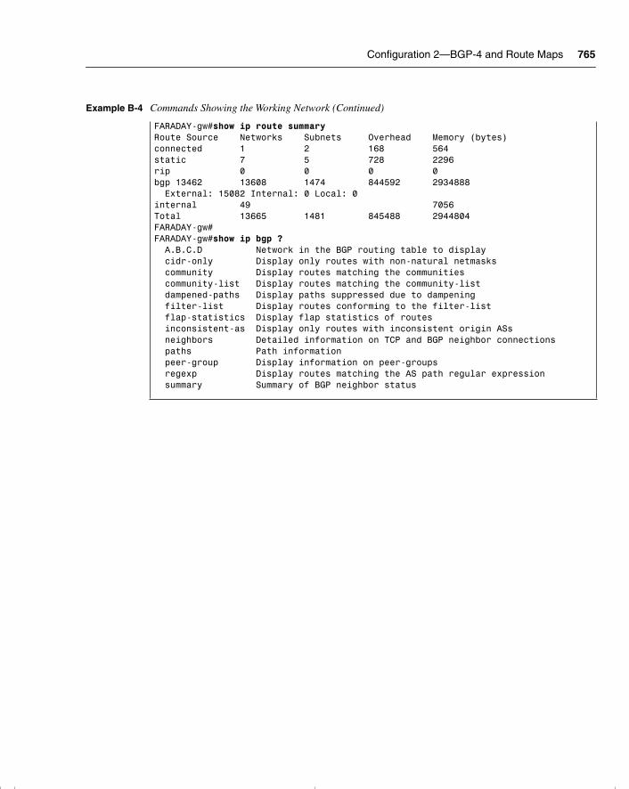
Configuration 2—BGP-4 and Route Maps 765
FARADAY-gw#show ip route summaryRoute Source Networks Subnets Overhead Memory (bytes)connected 1 2 168 564static 7 5 728 2296rip 0 0 0 0bgp 13462 13608 1474 844592 2934888 External: 15082 Internal: 0 Local: 0internal 49 7056Total 13665 1481 845488 2944804FARADAY-gw# FARADAY-gw#show ip bgp ? A.B.C.D Network in the BGP routing table to display cidr-only Display only routes with non-natural netmasks community Display routes matching the communities community-list Display routes matching the community-list dampened-paths Display paths suppressed due to dampening filter-list Display routes conforming to the filter-list flap-statistics Display flap statistics of routes inconsistent-as Display only routes with inconsistent origin ASs neighbors Detailed information on TCP and BGP neighbor connections paths Path information peer-group Display information on peer-groups regexp Display routes matching the AS path regular expression summary Summary of BGP neighbor status
Example B-4 Commands Showing the Working Network (Continued)
chpt_01.book Page 765 Thursday, December 21, 2000 6:22 PM

chpt_01.book Page 766 Thursday, December 21, 2000 6:22 PM
A P P E N D I X C
Glossary
This glossary assembles and defines the terms and acronyms used in this book and used in the internetworking industry. Many of the definitions have yet to be standardized, and many terms have several meanings. Multiple definitions and acronym expressions are included where they apply. These definitions can be found on CCO at www.cisco.com under the title “Internetworking Terms and Acronyms.”
10BaseT. 10-Mbps baseband Ethernet specification using two pairs of twisted-pair cabling (Category 3, 4, or 5): one pair for transmitting data and the other for receiving data. 10BaseT, which is part of the IEEE 802.3 specification, has a distance limit of approximately 328 feet (100 meters) per segment.
802.x. Set of IEEE standards for the definition of LAN protocols.
AAAA. Authentication, authorization, and accounting (pronounced “triple a”).
ABR. Area Border Router. A router located on the border of one or more OSPF areas that connects those areas to the backbone network. ABRs are considered members of both the OSPF backbone and the attached areas. Therefore, they maintain routing tables describing both the backbone topology and the topology of the other areas.
access layer. Layer in a hierarchical network that provides workgroup/user access to the network.
access list. List kept by routers to control access to or from the router for a number of services (for example, to prevent packets with a certain IP address from leaving a particular interface on the router).
access method. Generally, the way in which network devices access the network medium.
chpt_01.book Page 767 Thursday, December 21, 2000 6:22 PM
768 access server
access server. Communications processor that connects asynchronous devices to a LAN or WAN through network and terminal emulation software. Performs both synchronous and asynchronous routing of supported protocols. Sometimes called a network access server (NAS).
accounting management. One of five categories of network management defined by ISO for management of OSI networks. Accounting management subsystems are responsible for collecting network data relating to resource usage.
accuracy. The percentage of useful traffic that is correctly transmitted on the system, relative to total traffic, including transmission errors.
ACF. Advanced Communications Function. A group of SNA products that provides distributed processing and resource sharing.
ACK. 1. Acknowledgment bit in a TCP segment. 2. See acknowledgment.
acknowledgment. Notification sent from one network device to another to acknowledge that some event (for example, receipt of a message) occurred. Sometimes abbreviated ACK. Compare with NAK.
ACL. See access list.
ACS. Access control server. This is a centralized security server that includes individual access control through network access servers and firewalls. It can also simultaneously control management access to routers and switches.
CiscoSecure Access Control Server is one of Cisco’s specialized security software soulutions for Authentication, Authorization, and Accounting (AAA). This range of servers provide TACACS+ or RADIUS-based AAA services, while leveraging Cisco IOS functionality for smooth interoperation.
active. Route state when a network change is seen but, on interrogation of the topology table, there is no FC. The router queries its neighbors for alternative routes.
address. A data structure or logical convention used to identify a unique entity, such as a particular process or network device.
address mapping. A technique that allows different protocols to interoperate by translating addresses from one format to another. For example, when routing IP over X.25, the IP addresses must be mapped to the X.25 addresses so that the IP packets can be transmitted by the X.25 network. See also address resolution.
chpt_01.book Page 768 Thursday, December 21, 2000 6:22 PM
algorithm 769
address resolution. Generally, a method for resolving differences between computer addressing schemes. Address resolution usually specifies a method for mapping network layer (Layer 3) addresses to data link layer (Layer 2) addresses.
adjacency. A relationship formed between selected neighboring routers and end nodes for the purpose of exchanging routing information. Adjacency is based on the use of a common media segment.
adjacent neighbors. A neighbor is a router that is directly connected to another router. Both neighbors must also have the same mask and hello parameters. An adjacent router is a router that has exchanged routing information with its neighbor.
administrative distance. A rating of the trustworthiness of a routing information source. The higher the value, the lower the trustworthiness rating. Used when multiple routing protocol are updating the IP routing table and another method than metric is required to select the best route.
ADSL. Asymmetric digital subscriber line. One of four DSL technologies. ADSL is designed to deliver more bandwidth downstream (from the central office to the customer site) than upstream. Downstream rates range from 1.5 to 9 Mbps, while upstream bandwidth ranges from 16 to 640 kbps. ADSL transmissions work at distances up to 18,000 feet (5,488 meters) over a single copper twisted-pair wire.
advertised distance (AD). The cost of the path to the remote network from the neighbor (the metric from the next-hop router).
agent. 1. Generally, software that processes queries and returns replies on behalf of an application. 2. In NMSs, a process that resides in all managed devices and reports the values of specified variables to management stations.
aggregated route. The consolidation of advertised addresses in a routing table. The use of summarizing routes reduces the number of routes in the routing table, the routing update traffic, and overall router overhead. Also called route summarization.
aggregation. See route summarization.
alarm. A message notifying an operator or administrator of a network problem.
algorithm. Well-defined rule or process for arriving at a solution to a problem. In networking, algorithms are commonly used to determine the best route for traffic from a particular source to a particular destination.
chpt_01.book Page 769 Thursday, December 21, 2000 6:22 PM
770 analog
analog. An electrical circuit that is represented by means of continuous, variable physical quantities (such as voltages and frequencies), as opposed to discrete representations (such as the 0/1, off/on representation of digital circuits).
analog transmission. Signal transmission over wires or through the air in which information is conveyed through variation of some combination of signal amplitude, frequency, and phase.
ANSI. American National Standards Institute. Voluntary organization composed of corporate, government, and other members that coordinates standards-related activities, approves U.S. national standards, and develops positions for the United States in international standards organizations. ANSI helps develop international and U.S. standards relating to, among other things, communications and networking. ANSI is a member of the IEC and the ISO.
API. Application programming interface. A specification of function-call conventions that defines an interface to a service.
APPC. Advanced Program-to-Program Communications. IBM SNA system software that allows high-speed communication between programs on different computers in a distributed computing environment. APPC runs on LU 6.2 devices.
AppleTalk. A series of communications protocols designed by Apple Computer. Two phases currently exist. Phase 1, the earlier version, supports a single physical network that can have only one network number and can be in one zone. Phase 2, the more recent version, supports multiple logical networks on a single physical network and allows networks to be in more than one zone. See also zone.
application layer. Layer 7 of the OSI reference model. This layer provides services to application processes (such as electronic mail, file transfer, and terminal emulation) that are outside the OSI model. The application layer identifies and establishes the availability of intended communication partners (and the resources required to connect with them), synchronizes cooperating applications, and establishes agreement on procedures for error recovery and control of data integrity. It corresponds roughly with the transaction services layer in the SNA model.
ARAP. AppleTalk Remote Access Protocol. Protocol that provides Macintosh users direct access to information and resources at a remote AppleTalk site.
area. A logical set of network segments and their attached devices. Areas are usually connected to other areas via routers, making up a single autonomous system. See also AS. Used in DECnet, IS-IS, and OSPF.
chpt_01.book Page 770 Thursday, December 21, 2000 6:22 PM
ATM 771
ARP. Address Resolution Protocol. An Internet protocol used to map an IP address to a MAC address. It is defined in RFC 826.
ARPA. Advanced Research Projects Agency. Research and development organization that is part of the United States Department of Defense. ARPA is responsible for numerous technological advances in communications and networking. ARPA evolved into DARPA and then back into ARPA again (in 1994). It is responsible for Ethernet II and the frame structure.
ARPANET. Advanced Research Projects Agency Network. Landmark packet-switching network established in 1969. ARPANET was developed in the 1970s by BBN and was funded by ARPA (and later DARPA). It eventually evolved into the Internet. The term ARPANET was officially retired in 1990.
AS. Autonomous system. A collection of networks under a common administration sharing a common routing strategy. Autonomous systems may be subdivided into areas.
ASA. Adaptive security algorithm used in Cisco’s PIX firewall.
ASBR. Autonomous System Boundary Router. An ABR located between an OSPF autonomous system and a non-OSPF network. ASBRs run both OSPF and another routing protocol, such as RIP. ASBRs must reside in a nonstub OSPF area.
ASCII. American Standard Code for Information Interchange. An 8-bit code for character representation (7 bits plus parity).
assigned numbers. RFC [STD2] documents the currently assigned values from several series of numbers used in network protocol implementations. This RFC is updated periodically, and current information can be obtained from IANA. If you are developing a protocol or application that will require the use of a link, socket, port, protocol, and so forth, contact IANA to receive a number assignment.
asynchronous transmission. Term describing digital signals that are transmitted without precise clocking. Such signals generally have different frequencies and phase relationships. Asynchronous transmissions usually encapsulate individual characters in control bits (called start and stop bits) that designate the beginning and end of each character.
ATM. Asynchronous Transfer Mode. An international standard for cell relay in which multiple service types (such as voice, video, or data) are conveyed in fixed-length (53-byte) cells. Fixed-length cells allow cell processing to occur in hardware, thereby reducing transit delays. ATM is designed to take advantage of high-speed transmission media, such as E3, SONET, and T3.
chpt_01.book Page 771 Thursday, December 21, 2000 6:22 PM
772 attribute
attribute. The metric used by BGP-4.
AUI. Attachment unit interface. IEEE 802.3 interface between an MAU and a NIC. The term AUI can also refer to the rear panel port to which an AUI cable might attach.
authentication. In security, the verification of the identity of a person or process.
autonomous switching. Feature on Cisco routers that provides faster packet processing by allowing the ciscoBus to switch packets independently without interrupting the system processor.
autonomous system. Term that defines the organizational boundary. Within the terminology of the routing protocols, it defines all the routers within an administrative domain, where each router has full knowledge of the subnets within the domain. This becomes confused with the introduction of summarization within an autonomous system. If you are connecting directly to the Internet using BGP, the autonomous system number must be unique and obtained from the Internet addressing committees.
average rate. Average rate, in kilobits per second (kbps), at which a given virtual circuit will transmit.
Bbackbone. Part of a network that acts as the primary path for traffic that is most often sourced from and destined for other networks.
backward explicit congestion notification. See BECN.
bandwidth. Difference between the highest and lowest frequencies available for network signals. The term is also used to describe the rated throughput capacity of a given network medium or protocol.
bandwidth reservation. Process of assigning bandwidth to users and applications served by a network. It involves assigning priority to different flows of traffic based on how critical and delay-sensitive they are. This makes the best use of available bandwidth; if the network becomes congested, lower-priority traffic can be dropped. This sometimes is called bandwidth allocation.
Basic Rate Interface. See BRI.
baud. Unit of signaling speed equal to the number of discrete signal elements transmitted per second. Baud is synonymous with bits per second (bps) if each signal element represents exactly 1 bit.
chpt_01.book Page 772 Thursday, December 21, 2000 6:22 PM
BOD 773
Bc. Committed burst. Negotiated tariff metric in Frame Relay internetworks. The maximum amount of data (in bits) that a Frame Relay internetwork is committed to accept and transmit at the CIR.
B channel. Bearer channel. This is an ISDN communication channel that bears or carries voice, circuit, or packet conversations. The B channel is the fundamental component of ISDN interfaces. It carries 64,000 bps in either direction. See also bearer channel.
BDR. Backup designated router. Used in OSPF as a backup to the designated router.
Be. Excess burst. Negotiated tariff metric in Frame Relay internetworks. This is the number of bits that a Frame Relay internetwork will attempt to transmit after Bc is accommodated. Be data, in general, is delivered with a lower probability than Bc data because Be data can be marked as DE by the network. See also Bc and De.
Bearer channel. See B channel.
BECN. Backward explicit congestion notification. A bit set by a Frame Relay network in frames traveling in the opposite direction of frames encountering a congested path. DTE receiving frames with the BECN bit set can request that higher-level protocols take flow control action as appropriate. Compare with FECN.
Bellman-Ford routing algorithm. See distance vector routing protocol.
best-effort delivery. Delivery in a network system that does not use a sophisticated acknowledgment system to guarantee reliable delivery of information.
BGP. Border Gateway Protocol. An interdomain routing protocol that replaces EGP. BGP exchanges reachability information with other BGP systems. It is defined in RFC 1163. See also BGP-4 and EGP.
BGP-4. BGP version 4. This is version 4 of the predominant interdomain routing protocol used on the Internet. BGP-4 supports CIDR and uses route aggregation mechanisms to reduce the size of routing tables. See also BGP.
BIA. Burned-in address; another name for a MAC address.
binary. Numbering system characterized by 1s and 0s (1 = on, 0 = off).
bit. Binary digit used in the binary numbering system. This can be 0 or 1.
BOD. Bandwidth on demand.
chpt_01.book Page 773 Thursday, December 21, 2000 6:22 PM
774 BRI
BRI. Basic Rate Interface. The most common kind of ISDN interface available in the United States. BRI contains two B channels, each with a capacity of 64 kbps, and a single D channel (with a capacity of 16 kbps) that is used for signaling and call progress messages. Compare with PRI.
broadcast. Data packet that will be sent to all nodes on a network. Broadcasts are identified by a broadcast address. Compare with multicast and unicast.
BSD (Berkeley Standard Distribution). Term used to describe any of a variety of UNIX-type operating systems based on the UC Berkeley BSD operating system.
buffer. Storage area used for handling data in transit. Buffers are used in internetworking to compensate for differences in processing speed between network devices. Bursts of data can be stored in buffers until they can be handled by slower processing devices. This sometimes is referred to as a packet buffer.
byte. Term used to refer to a series of consecutive binary digits that are operated upon as a unit (for example, an 8-bit byte).
Ccable. Transmission medium of copper wire or optical fiber wrapped in a protective cover.
CCITT. Consultative Committee for International Telegraph and Telephone. International organization responsible for the development of communications standards. It is now called the ITU-T. See ITU-T.
CCO. Cisco Connection Online. Cisco’s web site.
channel. Communication path. Multiple channels can be multiplexed over a single cable in certain environments.
Channelized E1. Access link operating at 2.048 Mbps that is subdivided into 30 B channels and 1 D channel. It supports DDR, Frame Relay, and X.25.
Channelized T1. Access link operating at 1.544 Mbps that is subdivided into 24 channels (23 B channels and 1 D channel) of 64 kbps each. The individual channels or groups of channels connect to different destinations. It supports DDR, Frame Relay, and X.25. It is also referred to as fractional T1.
chpt_01.book Page 774 Thursday, December 21, 2000 6:22 PM
CLI 775
CHAP. Challenge Handshake Authentication Protocol. Security feature supported on lines using PPP encapsulation that prevents unauthorized access. CHAP does not itself prevent unauthorized access; it merely identifies the remote end. The router or access server then determines whether that user is allowed access. Compare to PAP.
chat script. String of text that defines the login “conversation” that occurs between two systems. Consists of expect-send pairs that define the string that the local system expects to receive from the remote system and then determine what the local system should send as a reply.
checksum. Method for checking the integrity of transmitted data. A checksum is an integer value computed from a sequence of octets taken through a series of arithmetic operations. The value is recomputed at the receiving end and is compared for verification.
CIDR (classless interdomain routing). The means by which the Internet assigns blocks of addresses, typically Class C addresses, and summarizes them by using the prefix mask.
CIR. Committed information rate. Rate at which a Frame Relay network agrees to transfer information under normal conditions, averaged over a minimum increment of time. CIR, measured in bits per second, is one of the key negotiated tariff metrics. See also Bc.
circuit. Communications path between two or more points.
Cisco Express Forwarding (CEF). Advanced, Layer 3 IP switching technology. CEF optimizes network performance and scalability for networks with large and dynamic traffic patterns, such as the Internet, on networks characterized by intensive web-based applications or interactive sessions.
CiscoSecure. A complete line of access-control software products that complement any dial network solution, enabling the centralization of security policies.
classful routing protocols. Routing protocols that do not transmit any information about the prefix length. Examples are RIP and IGRP.
classless routing protocols. Routing protocols that include the prefix length with routing updates; routers running classless routing protocols do not have to determine the prefix themselves. Classless routing protocols support VLSM.
CLI. Command-line interface. An interface that enables the user to interact with the operating system by entering commands and optional arguments.
chpt_01.book Page 775 Thursday, December 21, 2000 6:22 PM
776 client
client. A node or software program that requests services from a server. See also server.
client/server computing. Computing (processing) network systems in which transaction responsibilities are divided into two parts: client (front end) and server (back end). Both terms (client and server) can be applied to software programs or actual computing devices. This is also called distributed computing (processing).
cluster-ID. The cluster-ID is another attribute used in configuring route reflectors. If the cluster has more than one route reflector, the cluster-ID is used to recognize updates from other route reflectors within the cluster.
collapsed backbone. A nondistributed backbone in which all network segments are interconnected by way of an internetworking device. A collapsed backbone might be a virtual network segment existing in a device such as a hub, a router, or a switch.
collision. In Ethernet, the result of two nodes transmitting simultaneously. The frames from each device impact and are damaged when they meet on the physical media.
committed burst. See Bc.
committed information rate. See CIR.
common carrier. Licensed, private utility company that supplies communication services to the public at regulated prices.
common transport semantic. Clear To Send signal. Circuit in the EIA/TIA-232 specification that is activated when the DCE is ready to accept data from the DTE.
connection-orientated. When the software on two end nodes guarantees the transmission of network traffic, because a circuit setup is established before sending any data. It requires the use of sequencing, windowing, and acknowledgements.
convergence. Speed and capability of a group of internetworking devices running a specific routing protocol to agree on the topology of an internetwork after a change in that topology.
cost. An arbitrary value, typically based on hop count, media bandwidth, or other measures, that is assigned by a network administrator and used to compare various paths through an internetwork environment. Cost values are used by routing protocols to determine the most favorable path to a particular destination: The lower the cost, the better the path. In OSPF, this is the value assigned to a link. This metric is based on the speed of the media. It is sometimes called path cost.
chpt_01.book Page 776 Thursday, December 21, 2000 6:22 PM
data-link connection identifier 777
count to infinity. Problem that can occur in routing algorithms that are slow to converge, in which routers continuously increment the hop count to particular networks. Typically, some arbitrary hop-count limit is imposed to prevent this problem.
CPE. Customer premises equipment. Terminating equipment, such as terminals, telephones, and modems, supplied by the telephone company, installed at customer sites, and connected to the telephone company network.
CR. Carriage return.
CRC. Cyclic redundancy check. Error-checking technique in which the frame recipient calculates a remainder by dividing frame contents by a prime binary divisor and then comparing the calculated remainder to a value stored in the frame by the sending node.
CSU. Channel service unit. Digital interface device that connects end-user equipment to the local digital telephone loop. It is often referred to, together with DSU, as CSU/DSU. See also DSU.
customer premises equipment. See CPE.
cyclic redundancy check. See CRC.
DDARPA. Defense Advanced Research Projects Agency. U.S. government agency that funded research for and does experimentation with the Internet. It evolved from ARPA and then, in 1994, back to ARPA.
Data Encryption Standard. See DES.
Data Network Identification Code. See DNIC.
data terminal equipment. See DTE.
datagram. Logical grouping of information sent as a network layer unit over a transmission medium without prior establishment of a virtual circuit. IP datagrams are the primary information units in the Internet. The terms cell, frame, message, packet, and segment are also used to describe logical information groupings at various layers of the OSI reference model and in various technology circles.
data-link connection identifier. See DLCI.
chpt_01.book Page 777 Thursday, December 21, 2000 6:22 PM
778 DB
DB. Data bus connector. Type of connector used to connect serial and parallel cables to a data bus. DB connector names are in the format DB-x, where x represents the number of wires within the connector. Each line is connected to a pin on the connector, but in many cases, not all pins are assigned a function. DB connectors are defined by various EIA/TIA standards.
DCE. Data circuit-terminating equipment (ITU-T expansion). Devices and connections of a communications network that comprise the network end of the user-to-network interface. The DCE provides a physical connection to the network, forwards traffic, and provides a clocking signal used to synchronize data transmission between DCE and DTE devices. Modems and interface cards are examples of DCE. Compare with DTE.
DDR. Dial-on-demand routing. Technique whereby a router can automatically initiate and close a circuit-switched session as transmitting stations demand. The router spoofs keepalives so that end stations treat the session as active. DDR permits routing over ISDN or telephone lines using an external ISDN terminal adapter or modem.
DE. Discard eligible indicator. When the router detects network congestion, the FR switch will drop packets with the DE bit set first. The DE bit is set on the oversubscribed traffic—that is, the traffic that was received after the CIR was sent.
decryption. Reverse application of an encryption algorithm to encrypted data, thereby restoring that data to its original, unencrypted state. See also encryption.
dedicated line. Communications line that is indefinitely reserved for transmissions rather than switched as transmission is required. See also leased line.
default route. A routing table entry that is used to direct packets for which a next hop is not explicitly listed in the routing table.
default router. The router to which frames are directed when a next hop is not explicitly listed in the routing table. Also called a default gateway.
delay. Time between the initiation of a transaction by a sender and the first response received by the sender. Also, the time required to move a packet from source to destination over a given path.
demarc. Demarcation point between carrier equipment and CPE.
DES. Data Encryption Standard. Standard cryptographic algorithm developed by the U.S. National Bureau of Standards.
chpt_01.book Page 778 Thursday, December 21, 2000 6:22 PM
DLCI 779
destination address. Address of a network device that is receiving data. See also source address.
DHCP (Dynamic Host Configuration Protocol). Provides a mechanism for allocating IP addresses dynamically so that addresses can be reused when hosts no longer need them.
dial backup. Feature that provides protection against WAN downtime by allowing the network administrator to configure a backup serial line through a circuit-switched connection.
dial-on-demand routing. See DDR.
dialup line. Communications circuit that is established by a switched-circuit connection using the telephone company network.
Diffusing Update Algorithm (DUAL). An algorithm performed on the topology table to converge the network. It is based on a router detecting a network change within a finite time, with the change being sent reliably and in sequence. Because the algorithm is calculated simultaneously, in order, and within a finite time frame on all affected routers, it ensures a loop-free network.
digital. The use of a binary code to represent information, such as 0/1 or on/off.
Dijkstra algorithm. Routing algorithm that iterates on length of path to determine a shortest-path spanning tree. Commonly used in link-state routing algorithms. Sometimes called shortest path first algorithm.
distance vector routing protocol. Class of routing algorithms that iterate on the number of hops in a route to find a shortest-path spanning tree. Distance vector routing algorithms call for each router to send its entire routing table in each update, but only to its neighbors. Distance vector routing algorithms can be prone to routing loops, but they are computationally simpler than link-state routing algorithms. These routing protocols are also called Bellman-Ford routing algorithms.
distribute list. An access list that is applied to the routing protocol. It is used to control routing updates by filtering out those updates that are not to be propagated. This is particularly useful in preventing routing loops in redistributed networks.
DLCI. Data-link connection identifier. Value that specifies a PVC or an SVC in a Frame Relay network. In the basic Frame Relay specification, DLCIs are locally significant (connected devices might use different values to specify the same connection). In the LMI extended specification, DLCIs are globally significant (DLCIs specify individual end devices). See also LMI.
chpt_01.book Page 779 Thursday, December 21, 2000 6:22 PM
780 DNIC
DNIC. Data Network Identification Code. Part of an X.121 address. DNICs are divided into two parts, with the first specifying the country in which the addressed PSN is located, and the second specifying the PSN itself.
DNS (Domain Name System). System used in the Internet for translating names of network nodes into addresses.
DoD. Department of Defense. U.S. government organization that is responsible for national defense. The DoD has frequently funded communication protocol development.
domain. In the Internet, a portion of the naming hierarchy tree that refers to general groupings of networks based on organization type or geography.
Domain Name System. See DNS.
dot address. Refers to the common notation for IP addresses in the form n.n.n.n, where each number n represents, in decimal, 1 byte of the 4-byte IP address. This is also called dotted notation or four-part dotted notation.
dotted decimal notation. Syntactic representation for a 32-bit integer that consists of four 8-bit numbers written in base 10 with periods (dots) separating them. It is used to represent IP addresses in the Internet, as in 192.67.67.20. This is also called dotted quad notation.
DR. Designated router. Used in OSPF on multiaccess links. The router is responsible for maintaining the routing tables of the other OSPF routers on the same link. All the routers on the link form an adjacency with the designated router.
DS. Digital signal.
DS0. Digital signal level 0. Framing specification used in transmitting digital signals over a single channel at 64 kbps on a T1 facility. Compare with DS1 and DS3.
DS1. Digital signal level 1. Framing specification used in transmitting digital signals at 1.544 Mbps on a T1 facility (in the United States), or at 2.108 Mbps on an E1 facility (in Europe). Compare with DS0 and DS3.
DS3. Digital signal level 3. Framing specification used for transmitting digital signals at 44.736 Mbps on a T3 facility. Compare with DS0 and DS1.
DSL. Digital subscriber line. Public network technology that delivers high bandwidth over conventional copper wiring at limited distances. There are four types of DSL: ADSL, HDSL, SDSL, and VDSL. All are provisioned via modem pairs, with one
chpt_01.book Page 780 Thursday, December 21, 2000 6:22 PM
EIA/TIA-232 781
modem located at a central office and the other at the customer site. Because most DSL technologies do not use the whole bandwidth of the twisted pair, there is room remaining for a voice channel. See also ADSL and HDSL.
DSU. Data service unit. Device used in digital transmission that adapts the physical interface on a DTE device to a transmission facility such as T1 or E1. The DSU is also responsible for such functions as signal timing. It is often referred to, together with CSU, as CSU/DSU. See also CSU.
DTE. Data terminal equipment. Device at the user end of a user-network interface that serves as a data source, a destination, or both. DTE connects to a data network through a DCE device (for example, a modem) and typically uses clocking signals generated by the DCE. DTE includes such devices as computers, protocol translators, and multiplexers. Compare with DCE.
DUAL. See Diffusing Update Algorithm.
dynamic address resolution. Use of an address resolution protocol to determine and store address information on demand.
dynamic routes. Automatic rerouting of traffic based on sensing and analyzing current actual network conditions, not including cases of routing decisions taken on predefined information.
EE1. Wide-area digital transmission scheme used predominantly in Europe that carries data at a rate of 2.048 Mbps. E1 lines can be leased for private use from common carriers. Compare with T1. See also DS1.
EGP. Exterior Gateway Protocol. An Internet protocol for exchanging routing information between autonomous systems. It is documented in RFC 904. This is not to be confused with the general term exterior gateway protocol; EGP is an obsolete protocol that has been replaced by BGP.
EIA/TIA. Electronic Industries Association/Telecommunications Industry Association.
EIA/TIA-232. Common physical layer interface standard, developed by EIA and TIA, that supports unbalanced circuits at signal speeds of up to 64 kbps. It closely resembles the V.24 specification. It was formerly called RS-232.
chpt_01.book Page 781 Thursday, December 21, 2000 6:22 PM
782 EIGRP
EIGRP. Enhanced Interior Gateway Routing Protocol. An advanced version of IGRP developed by Cisco. It provides superior convergence properties and operating efficiency, and combines the advantages of link-state protocols with those of distance vector protocols.
e-mail. Electronic mail. Widely used network application in which text messages are transmitted electronically between end users over various types of networks using various network protocols.
encapsulation. Wrapping of data in a particular protocol header. For example, Ethernet data is wrapped in a specific Ethernet header before network transit. Also, when bridging dissimilar networks, the entire frame from one network is simply placed in the header used by the data link layer protocol of the other network.
encryption. Application of a specific algorithm to data to alter the appearance of the data, making it incomprehensible to those who are not authorized to see the information. See also decryption.
end node. A device that is connected to the network.
Enhanced IGRP. See EIGRP.
excess burst. See Be.
Extended Super Frame. ESF. Framing type used on T1 circuits that consists of 24 frames of 192 bits each, with the 193rd bit providing timing and other functions. ESF is an enhanced version of SF.
Exterior Gateway Protocol (EGP). Protocol that runs between autonomous systems. A protocol with this name was the precursor to BGP.
exterior routing. A routing protocol used to exchange information between autonomous systems or organizations, used to connect organizations into the Internet. BGP and EGP are examples of exterior routing protocols.
exterior routing protocols. See Exterior Gateway Protocol.
external BGP. BGP is used to connect different autonomous systems.
chpt_01.book Page 782 Thursday, December 21, 2000 6:22 PM
first octet rule 783
Ffast switching. A cache in the Cisco router that contains routing decisions. When the routing decision for a packet has been made, it can be cached in any one of a variety of caches. This means that the forwarding of traffic throughout the router is greatly enhanced.
FCC. Federal Communications Commission. U.S. government agency that supervises, licenses, and controls electronic and electromagnetic transmission standards.
FCS. Frame check sequence. Extra characters added to a frame for error control purposes. This is used in HDLC, Frame Relay, and other data link layer protocols.
feasible condition (FC). When a neighbor reports a path (AD) that is lower than the router’s FD to a network, the neighbor’s (next-hop router’s) path has a lower metric than the router’s path.
feasible distance (FD). The lowest-cost distance (metric) to a remote network.
feasible successor (FS). The neighbor reporting the AD that is lower than the router’s FD becomes the feasible successor. This is the next-hop router that meets the FC.
FECN. Forward explicit congestion notification. Bit set by a Frame Relay network to inform the DTE receiving the frame that congestion was experienced in the path from the source to the destination. The DTE receiving frames with the FECN bit set can request that higher-level protocols take flow-control action as appropriate. Compare with BECN.
FIFO. First in, first out. With FIFO, transmission occurs in the same order as messages are received.
filter. Generally, a process or device that screens network traffic for certain characteristics, such as source address, destination address, or protocol, and determines whether to forward or discard that traffic based on the established criteria.
firewall. Router or access server, or several routers or access servers, designated as a buffer between any connected public networks and a private network. A firewall router uses access lists and other methods to ensure the security of the private network.
first octet rule. The mechanism by which the Layer 3 device identifies the class of IP address. If the protocol is a classful address, it is the only means available to determine the network portion of an address to which it is not directly connected.
chpt_01.book Page 783 Thursday, December 21, 2000 6:22 PM
784 flapping
flapping. Intermittent interface failures.
flash update. A routing update sent asynchronously in response to a change in the network topology. Compare with routing update.
floating static route. A static route that has a higher administrative distance than a dynamically learned route so that it can be overridden by dynamically learned routing information. Used to create a DDR backup to an existing link.
flood. A term that refers to network information. When it is flooded, it is sent to every network device in the domain.
flooding. A traffic-passing technique used by switches and bridges in which traffic received on an interface is sent out to all the interfaces of that device, except the interface on which the information was originally received.
flow. Stream of data traveling between two endpoints across a network (for example, from one LAN station to another). Multiple flows can be transmitted on a single circuit.
flow control. Technique for ensuring that a transmitting entity, such as a modem, does not overwhelm a receiving entity with data. When the buffers on the receiving device are full, a message is sent to the sending device to suspend the transmission until the data in the buffers has been processed.
FR. See Frame Relay.
fragmentation. Process of breaking a packet into smaller units when transmitting over a network medium that cannot support the original size of the packet.
frame. Logical grouping of information sent as a data link layer unit over a transmission medium. This often refers to the header and trailer, used for synchronization and error control, that surround the user data contained in the unit. The terms cell, datagram, message, packet, and segment are also used to describe logical information groupings at various layers of the OSI reference model and in various technology circles.
Frame Relay. Industry-standard, switched data link layer protocol that handles multiple virtual circuits using HDLC encapsulation between connected devices. Frame Relay is more efficient than X.25, the protocol for which it is generally considered a replacement. See also X.25.
frequency. Number of cycles, measured in hertz, of an alternating current signal per unit time.
chpt_01.book Page 784 Thursday, December 21, 2000 6:22 PM
header 785
FTP. File Transfer Protocol. Application protocol, part of the TCP/IP protocol stack, used for transferring files between network nodes. FTP is defined in RFC 959.
full duplex. Capability for simultaneous data transmission between a sending station and a receiving station.
full mesh. Term describing a network in which devices are organized in a mesh topology, with each network node having either a physical circuit or a virtual circuit connecting it to every other network node. A full mesh provides a great deal of redundancy, but because it can be prohibitively expensive to implement, it is usually reserved for network backbones. See also mesh and partial mesh.
fully adjacent. When the routing tables of the two neighbors are fully synchronized, with exactly the same view of the network.
G - Hgateway. In the IP community, an older term referring to a routing device. Today, the term router is used to describe nodes that perform this function, and gateway refers to a special-purpose device that performs an application layer conversion of information from one protocol stack to another.
half duplex. Capability for data transmission in only one direction at a time between a sending station and a receiving station.
HDLC. High-Level Data Link Control. Bit-oriented synchronous data link layer protocol developed by ISO. Derived from SDLC, HDLC specifies a data encapsulation method on synchronous serial links using frame characters and checksums.
HDSL. High data-rate digital subscriber line. One of four DSL technologies. HDSL delivers 1.544 Mbps of bandwidth each way over two copper twisted-pair wires. Because HDSL provides T1 speed, telephone companies have been using HDSL to provision local access to T1 services whenever possible. The operating range of HDSL is limited to 12,000 feet (3658.5 meters), so signal repeaters are installed to extend the service. HDSL requires two twisted-pair wires, so it is deployed primarily for PBX network connections, digital loop carrier systems, interexchange POPs, Internet servers, and private data networks. Compare with ADSL.
header. Control information placed before data when encapsulating that data for network transmission.
chpt_01.book Page 785 Thursday, December 21, 2000 6:22 PM
786 hello
hello. Hellos are used to find and maintain neighbors in the topology table. They are sent periodically and are sent reliably.
Hello protocol. A protocol used by OSPF systems for establishing and maintaining neighbor relationships.
High-Speed Serial Interface. See HSSI.
holddown. A state into which a route is placed so that routers will neither advertise the route nor accept advertisements about the route for a specific length of time (the holddown period); in this way, the entire network has a chance to learn about the change. Holddown is used to flush bad information about a route from all routers in the network. A route is typically placed in holddown when a link in that route fails.
holdtime. The holdtime is sent in the hello packet. It determines how long the router waits for hellos from a neighbor before declaring it unavailable. This information is held in the neighbor table.
hop. The passage of a data packet between two network nodes (for example, between two routers). See also hop count.
hop count. A routing metric used to measure the distance between a source and a destination. IP RIP uses hop count as its sole metric.
HSRP. Hot Standby Router Protocol. Provides a way for IP workstations to keep communicating on the internetwork even if their default router becomes unavailable, thereby providing high network availability and transparent network topology changes.
HSSI. High-Speed Serial Interface. Network standard for high-speed (up to 52-Mbps) serial connections over WAN links.
hub. Hardware or software device that contains multiple independent but connected modules of network and internetwork equipment. Hubs can be active (when they repeat signals sent through them) or passive (when they do not repeat, but merely split signals sent through them).
II/O. Input/output. Typically used when discussing ports on a device where data comes in or goes out.
chpt_01.book Page 786 Thursday, December 21, 2000 6:22 PM
Internet 787
IANA (Internet Assigned Numbers Authority). Responsible for address allocation in the Internet.
ICMP. Internet Control Message Protocol. Network layer Internet protocol that reports errors and provides other information relevant to IP packet processing. It is documented in RFC 792.
IDN. International data number. ITU-T standard describing an addressing scheme used in X.25 networks. X.121 addresses are sometimes called IDNs.
IEEE. Institute of Electrical and Electronic Engineers. Professional organization whose activities include the development of communications and network standards. IEEE LAN standards are the predominant LAN standards today.
IETF. Internet Engineering Task Force. Task force consisting of more than 80 working groups responsible for developing Internet standards. The IETF operates under the auspices of ISOC.
IGP. Interior Gateway Protocol. An Internet protocol used to exchange routing information within an autonomous system. Examples of common Internet IGPs include IGRP, OSPF, and RIP.
IGRP. Interior Gateway Routing Protocol. An IGP developed by Cisco to address the problems associated with routing in large, heterogeneous networks. Compare with Enhanced IGRP.
incremental update. A routing update that is sent only when there is a change in the topology, not periodically when a timer expires.
Integrated Services Digital Network. See ISDN.
Interior Gateway Protocol (IGP). In the past, the term gateway was used to define a router. This is a routing protocol that runs within an autonomous system.
interior routing protocols. Routing protocols used by routers within the same autonomous system, such as RIP, IGRP, and Enhanced IGRP.
internal BGP. BGP used to connect routers resident in the same autonomous system.
Internet. A term that refers to the largest global internetwork, connecting tens of thousands of networks worldwide and having a “culture” that focuses on research and standardization based on real-life use. Many leading-edge network technologies come
chpt_01.book Page 787 Thursday, December 21, 2000 6:22 PM
788 internet
from the Internet community. The Internet evolved in part from ARPANET. At one time, it was called the DARPA Internet. This is not to be confused with the general term internet.
internet. Short for internetwork. Not to be confused with the Internet. See also internetwork.
internetwork. A collection of networks interconnected by routers and other devices that functions (generally) as a single network. It is sometimes called an internet, which is not to be confused with the Internet.
internetworking. The industry that has arisen around the problem of connecting networks. The term can refer to products, procedures, and technologies.
intranet. A network, internal to an organization, based on Internet and World Wide Web technology, that delivers immediate, up-to-date information and services to networked employees.
IOS. Internetwork Operating System.
IP. Internet Protocol. A network layer protocol in the TCP/IP stack offering a connectionless internetwork service. IP provides features for addressing, type-of-service specification, fragmentation and reassembly, and security. It is documented in RFC 791.
IP address. A 32-bit address assigned to hosts using TCP/IP. An IP address belongs to one of five classes (A, B, C, D, or E) and is written as four octets separated with periods (dotted decimal format). Each address consists of a network number, an optional subnetwork number, and a host number. The network and subnetwork numbers together are used for routing, and the host number is used to address an individual host within the network or subnetwork. A subnet mask is used to extract network and subnetwork information from the IP address. It is also called an Internet address.
IP multicast. A routing technique that allows IP traffic to be propagated from one source to a number of destinations or from many sources to many destinations. Rather than send one packet to each destination, one packet is sent to a multicast group identified by a single IP destination group address.
IPSec. Standards-based method of providing privacy, integrity, and authenticity to information transferred across IP networks. It provides IP network layer encryption.
chpt_01.book Page 788 Thursday, December 21, 2000 6:22 PM
jitter 789
IPv6. IP version 6. Replacement for the current version of IP (version 4). IPv6 includes support for flow ID in the packet header, which can be used to identify flows. It formerly was called IPng (IP next generation).
IPX. Internetwork Packet Exchange. A NetWare network layer (Layer 3) protocol used for transferring data from servers to workstations.
IPX address. An IPX address is 80 bits long, with 32 bits for the network number and 48 bits for the node number.
IS. Information systems. A broad term used to describe the use of information technology in organizations. This includes the movement, storage, and use of information.
ISDN. Integrated Services Digital Network. Communication protocol offered by telephone companies that permits telephone networks to carry data, voice, and other source traffic.
IS-IS. Intermediate System-to-Intermediate System. An OSI link-state hierarchical routing protocol based on DECnet Phase V routing whereby ISs (routers) exchange routing information based on a single metric to determine network topology.
ISO. International Organization for Standardization. International organization that is responsible for a wide range of standards, including those relevant to networking. The ISO developed the OSI reference model, a popular networking reference model.
ISOC. Internet Society. International nonprofit organization, founded in 1992, that coordinates the evolution and use of the Internet. In addition, ISOC delegates authority to other groups related to the Internet, such as the IAB. ISOC is headquartered in Reston, Virginia (United States).
ISP. Internet service provider. Company that provides Internet access to other companies and individuals.
ITU-T. International Telecommunication Union–Telecommunication Standardization Sector. International body that develops worldwide standards for telecommunications technologies. The ITU-T carries out the functions of the former CCITT.
J - Kjitter. Analog communication line distortion caused by the variation of a signal from its reference timing positions. Jitter can cause data loss, particularly at high speeds.
chpt_01.book Page 789 Thursday, December 21, 2000 6:22 PM
790 Kb
Kb. Kilobit. Approximately 1,000 bits.
kbps. Kilobits per second.
keepalive. Message sent by one network device to inform another network device that the virtual circuit between the two is still active.
keepalive message. A message sent by one network device to inform another network device that the circuit between the two is still active.
Kerberos. Developing standard for authenticating network users. Kerberos offers two key benefits: It functions in a multivendor network, and it does not transmit passwords over the network.
LLAN. Local-area network. High-speed, low-error data network covering a relatively small geographic area (up to a few thousand meters). LANs connect workstations, peripherals, terminals, and other devices in a single building or other geographically limited area. LAN standards specify cabling and signaling at the physical and data link layers of the OSI model. Ethernet, FDDI, and Token Ring are widely used LAN technologies. Also see MAN and WAN.
LAPB. Link Access Procedure, Balanced. Data link layer protocol in the X.25 protocol stack. LAPB is a bit-oriented protocol derived from HDLC.
LAPD. Link Access Procedure on the D channel. ISDN data link layer protocol for the D channel. LAPD was derived from the LAPB protocol and is designed primarily to satisfy the signaling requirements of ISDN basic access. It is defined by ITU-T recommendations Q.920 and Q.921.
Layer 3 switching. Used in the context of VLANs, the mechanism by which a switch will route between VLANs. It also refers to routers, when the routing decision has been made and the result has been cached. The subsequent lookup involves switching (such as fast switching), but on a Layer 3 decision.
leased line. Transmission line reserved by a communications carrier for the private use of a customer. A leased line is a type of dedicated line. See also dedicated line.
LED. Light emitting diode. Semiconductor device that emits light produced by converting electrical energy. Status lights on hardware devices are typically LEDs.
chpt_01.book Page 790 Thursday, December 21, 2000 6:22 PM
LSA (link-state advertisement) 791
link. Network communications channel consisting of a circuit or transmission path and all related equipment between a sender and a receiver. It is most often used to refer to a WAN connection and sometimes is referred to as a line or a transmission link.
link-state routing algorithm. A routing algorithm in which each router broadcasts or multicasts information regarding the cost of reaching each of its neighbors to all nodes in the internetwork. Compare with distance vector routing protocol.
LMI. Local Management Interface. Set of enhancements to the basic Frame Relay specification. LMI includes support for a keepalive mechanism, which verifies that data is flowing; a multicast mechanism, which provides the network server with its local DLCI and the multicast DLCI; global addressing, which gives DLCIs global rather than local significance in Frame Relay networks; and a status mechanism, which provides an ongoing status report on the DLCIs known to the switch. It is known as LMT in ANSI terminology.
load balancing. In routing, the capability of a router to distribute traffic over all its network ports that are the same distance from the destination address. Good load-balancing algorithms use both line speed and reliability information. Load balancing increases the use of network segments, thus increasing effective network bandwidth.
loading state. During the process whereby two routers are creating an adjacency, if the receiving router requires more information, it will request that particular link in more detail, using the link-state request packet (LSR). The LSR will prompt the master router to send the link-state update packet (LSU). This is the same as a link-state advertisement (LSA) used to flood the network with routing information. While the receiving is awaiting the LSUs from its neighbor, it is in the loading state.
local loop. Also known as “the last mile.” Line from the premises of a telephone subscriber to the telephone company central office.
logical AND. The mechanism by which a subnet is derived from an IP host address. The router maps the subnet mask, in binary, onto the host address, in binary. The result of the logical AND is the subnet address.
loopback interface. A virtual interface that does not exist physically. This characteristic makes it very powerful: If it does not exist, it can never go down.
LSA (link-state advertisement). Broadcast packet used by link-state protocols that contains information about neighbors and path costs. LSAs are used by the receiving routers to maintain their routing tables. Sometimes called an LSP.
chpt_01.book Page 791 Thursday, December 21, 2000 6:22 PM
792 MAN
MMAN. Metropolitan-area network. Network that spans a metropolitan area. Generally, a MAN spans a larger geographic area than a LAN but a smaller geographic area than a WAN. Compare with LAN and WAN.
maximum transmission unit. See MTU.
MD5. Message digest algorithm 5. Algorithm used for message authentication. MD5 verifies the integrity of the communication, authenticates the origin, and checks for timeliness.
mesh. A network topology in which devices are organized in a manageable, segmented manner with many often redundant interconnections strategically placed between network nodes. See also full mesh and partial mesh.
message. An application layer (Layer 7) logical grouping of information, often composed of a number of lower-layer logical groupings such as packets.
metric. A standard of measurement, such as performance, that is used for measuring whether network management goals have been met.
modem. Modulator-demodulator. Device that converts digital and analog signals. At the source, a modem converts digital signals to a form suitable for transmission over analog communication facilities. At the destination, the analog signals are returned to their digital form. Modems allow data to be transmitted over voice-grade telephone lines.
modulation. Process by which the characteristics of electrical signals are transformed to represent information. Types of modulation include AM, FM, and PAM.
MP. Multilink Point-to-Point Protocol. Defined in the RFC 1717, it is sometimes referred to as MLPPP. It takes advantage of the ability of switched WAN services to open multiple virtual connections between devices to give users extra bandwidth as needed. This allows access devices to combine multiple PPP links into one logical data pipe.
MTU. Maximum transmission unit. Maximum packet size, in bytes, that a particular interface can handle.
multiaccess network. Network that allows multiple devices to connect and communicate simultaneously.
chpt_01.book Page 792 Thursday, December 21, 2000 6:22 PM
NetFlow 793
multicast. Single packets copied by the network and sent to a specific subset of network addresses. These addresses are specified in the Destination Address field. Compare with broadcast and unicast.
multiplexing. Scheme that allows multiple logical signals to be transmitted simultaneously across a single physical channel.
NNAK. Negative acknowledgment. Response sent from a receiving device to a sending device indicating that the information received contained errors. Compare to acknowledgment.
NAS. See access server.
NAT. Network Address Translation. Mechanism for reducing the need for globally unique IP addresses. NAT allows an organization with addresses that are not globally unique to connect to the Internet by translating those addresses into globally routable address space. Also known as Network Address Translator.
NBMA. Nonbroadcast multiaccess. Term describing a multiaccess network that does not support broadcasting (such as X.25) or in which broadcasting is not feasible (for example, an SMDS broadcast group or an extended Ethernet that is too large).
neighbor. A router running EIGRP that is directly connected.
neighbor table. A list of every neighbor, including the IP address, the outgoing interface, the holdtime, SRTT, and uptime, or how long since the neighbor was added to the table. The table is built from information on hellos received from adjacent routers (neighbors).
neighboring router. In OSPF or EIGRP, two routers that have interfaces to a common network.
NetBEUI. NetBIOS Extended User Interface. Enhanced version of the NetBIOS protocol used by network operating systems such as LAN Manager, LAN Server, Windows for Workgroups, and Windows NT. NetBEUI formalizes the transport frame and adds additional functions. NetBEUI implements the OSI LLC2 protocol.
NetFlow. A Cisco solution that enhances the speed of transmission by caching routing decisions.
chpt_01.book Page 793 Thursday, December 21, 2000 6:22 PM
794 network
network. Collection of computers, printers, routers, switches, and other devices that are capable of communicating with each other over some transmission medium.
network congestion. When excessive traffic on the network is the cause of delays and packet loss.
NNI. The standard interface between two Frame Relay switches meeting the same criteria.
nonstub area. A resource-intensive OSPF area that carries a default route, static routes, intra-area routes, interarea routes, and external routes. Compare with stub area. See also ASBR.
NVRAM. Nonvolatile random access memory.
OOC. Optical carrier. Series of physical protocols (OC-1, OC-2, OC-3, and so forth) defined for SONET optical signal transmissions. OC signal levels put STS frames onto multimode fiber-optic line at a variety of speeds. The base rate is 51.84 Mbps (OC-1); each signal level thereafter operates at a speed divisible by that number (thus, OC-3 runs at 155.52 Mbps).
octet. Eight bits. In networking, the term octet is often used (rather than byte) because some machine architectures employ bytes that are not 8 bits long.
ODBC. Open database connectivity.
OLE. Object linking and embedding. Compound document standard developed by Microsoft Corporation. It enables creating objects with one application and then linking or embedding them in a second application. These objects keep their original format and links to the application that created them.
originator-ID. A BGP-4 attribute. It is an optional nontransitive attribute that is created by the route reflector. The attribute contains the router ID of the router that originated the route in the update. The purpose of this attribute is to prevent a routing loop. If the originating router receives its own update, it ignores it.
OSI. Open System Interconnection. International standardization program created by ISO and ITU-T to develop standards for data networking that facilitate multivendor equipment interoperability.
chpt_01.book Page 794 Thursday, December 21, 2000 6:22 PM
partial mesh 795
OSI reference model. Open System Interconnection reference model. Network architectural model developed by ISO and ITU-T. The model consists of seven layers, each of which specifies particular network functions such as addressing, flow control, error control, encapsulation, and reliable message transfer. The lowest layer (the physical layer) is closest to the media technology. The lower two layers are implemented in hardware and software, while the upper five layers are implemented only in software. The highest layer (the application layer) is closest to the user. The OSI reference model is used universally as a method for teaching and understanding network functionality.
OSPF. Open Shortest Path First. A link-state, hierarchical IGP routing algorithm proposed as a successor to RIP in the Internet community. OSPF features include least-cost routing, multipath routing, and load balancing. OSPF was derived from an early version of the IS-IS protocol. See also EIGRP, IGP, IGRP, IS-IS, and RIP.
OUI. Organizationally unique identifier. Three octets assigned by the IEEE, used in the 48-bit MAC addresses.
Ppacket. Logical grouping of information that includes a header containing control information and (usually) user data. Packets are most often used to refer to network layer units of data. The terms datagram, frame, message, and segment are also used to describe logical information groupings at various layers of the OSI reference model and in various technology circles. See also PDU.
packet switching. Networking method in which nodes share bandwidth with each other by sending packets.
PAP. Password Authentication Protocol. Authentication protocol that allows PPP peers to authenticate one another. The remote router attempting to connect to the local router is required to send an authentication request. Unlike CHAP, PAP passes the password and host name or username in the clear (unencrypted). PAP does not itself prevent unauthorized access, but it merely identifies the remote end. The router or access server then determines whether that user is allowed access. PAP is supported only on PPP lines. Compare with CHAP.
partial mesh. Network in which devices are organized in a mesh topology, with some network nodes organized in a full mesh, but with others that are connected to only one or two other nodes in the network. A partial mesh does not provide the level of redundancy of a full-mesh topology, but it is less expensive to implement. Partial-mesh topologies are generally used in the peripheral networks that connect to a fully meshed backbone. See also full mesh and mesh.
chpt_01.book Page 795 Thursday, December 21, 2000 6:22 PM
796 passive
passive. An operational route is passive. If the path is lost, the router examines the topology table to find an FS. If there is an FS, it is placed in the routing table and the router does not query the others, which would send it into active mode.
PAT. Port Address Translation. A subset of NAT.
payload. Portion of a cell, frame, or packet that contains upper-layer information (data).
PDN. Public data network. Network operated either by a government (as in Europe) or by a private concern to provide computer communications to the public, usually for a fee. PDNs enable small organizations to create a WAN without all the equipment costs of long-distance circuits.
PDU. Protocol data unit. OSI term for packet.
peak rate. Maximum rate, in kilobits per second, at which a virtual circuit can transmit.
permanent virtual circuit (PVC). See PVC.
ping. Packet Internet groper. ICMP echo message and its reply. This is often used in IP networks to test the reachability of a network device.
PIX. Cisco’s Private Internet Exchange firewall. See also firewall.
playback. Reuse of a packet captured from a line by a sniffer.
point of demarcation. The physical point at which the phone company ends its responsibility with the wiring of the phone line.
poison reverse. Routing updates that specifically indicate that a network or subnet is unreachable, rather than implying that a network is unreachable by not including it in updates.
POP. Point of presence. A long-distance carrier’s office in your local community. A POP is the place where your long-distance carrier, or IXC, terminates your long-distance lines just before those lines are connected to your local phone company’s lines or to your own direct hookup. Each IXC can have multiple POPs within one LATA. All long-distance phone connections go through the POPs.
POTS. Plain old telephone service. See PSTN.
chpt_01.book Page 796 Thursday, December 21, 2000 6:22 PM
query 797
PPP. Point-to-Point Protocol. Successor to SLIP that provides router-to-router and host-to-network connections over synchronous and asynchronous circuits. Whereas SLIP was designed to work with IP, PPP was designed to work with several network layer protocols, such as IP, IPX, and ARA. PPP also has built-in security mechanisms, such as CHAP and PAP. PPP relies on two protocols: LCP and NCP. See also CHAP and PAP.
prefix list. These replace distribute lists for BGP-4. The prefix list is used to control how BGP-4 learns or advertises updates.
prefix mask. Identifies the number of bits in the subnet mask. It is written in the /xx format after the address. It is used in supernetting and router aggregation.
PRI. Primary Rate Interface. ISDN interface to primary rate access. Primary rate access consists of a single 64-Kbps D channel plus 23 (T1) or 30 (E1) B channels for voice or data. Compare with BRI.
private addressing. The means by which an organization can address its network without using a registered address from the Internet. This saves considerable address space in the Internet and eases restrictions within the organization.
process switching. The routing process within the Cisco router. This is resource-intensive.
PSTN. Public Switched Telephone Network. General term referring to the variety of telephone networks and services in place worldwide. Sometimes called POTS.
PTT. Poste, Telephone, Telegramme.
PVC. Permanent virtual circuit. Virtual circuit that is permanently established. PVCs save bandwidth associated with circuit establishment and teardown in situations in which certain virtual circuits must exist all the time. In ATM terminology, this is called a permanent virtual connection. See also SVC.
QQoS. Quality of service. A measure of performance for a transmission system that reflects its transmission quality and service availability.
query. Sent from the router when it loses a path to a network. If there is no alternate route (feasible successor), the router will send out queries to neighbors inquiring whether they have a feasible successor. This makes the route state change to active. The queries are sent reliably.
chpt_01.book Page 797 Thursday, December 21, 2000 6:22 PM
798 query scoping
query scoping. Another term for SIA.
queue. 1. Generally, an ordered list of elements waiting to be processed. 2. In routing, a backlog of packets waiting to be forwarded over a router interface.
RRADIUS. Database for authenticating modem and ISDN connections and for tracking connection time.
rate enforcement. See traffic policing.
redistribution. Exchanging routing updates between different routing protocols. This can be done only between protocols that support the same protocol suite at Layer 3—for example EIGRP and OSPF for TCP/IP. Redistribution cannot happen between Layer 3 protocols such as AppleTalk and IPX.
Reliable Transport Protocol (RTP). Requires that the packets be delivered in sequence and guaranteed.
reply. A response to the query. If a router has no information to send in a reply, it will send queries to all its neighbors. A unicast is sent reliably.
Retransmission Timeout (RTO). Timer calculated in reference to the SRTT. RTO determines how long the router waits for an ACK before retransmitting the packet.
RIP. 1. Routing Information Protocol. A distance vector IGP, RIP uses hop count as a routing metric. See also Enhanced IGRP, hop count, IGP, IGRP, and OSPF. 2. IPX Routing Information Protocol. A distance vector routing protocol for IPX.
RJ-45. Registered jack connector. Standard connectors used for 10BaseT and other types of network connections.
route reflector. The router that is configured to forward routes from other identified IBGP-4 clients. This removes the necessity for a fully meshed IBGP-4 network, which preserves network resources.
route reflector client. A client is a router that has a TCP session with its IBGP-4 peer. It forwards routes to the route reflector, which propagates these on to other routers. The client does not have peer connections with other clients.
route reflector cluster. A cluster is the group of route reflector and clients. There can be more than one route reflector in a cluster.
chpt_01.book Page 798 Thursday, December 21, 2000 6:22 PM
routing table 799
route summarization. The consolidation of advertised addresses in a routing table. Summarization of routes reduces the number of routes in the routing table, the routing update traffic, and overall router overhead. Also called route aggregation.
routed protocol. Protocol that can be routed by a router. A router must be capable of interpreting the logical internetwork as specified by that routed protocol. Examples of routed protocols include AppleTalk, DECnet, and IP.
router. A network layer device that uses one or more metrics to determine the optimal path along which network traffic should be forwarded. Routers forward packets from one network to another based on network layer information. It is occasionally called a gateway (although this definition of gateway is becoming increasingly outdated).
routing. The process of finding a path to a destination host. Routing is complex in large networks because of the many potential intermediate destinations that a packet might traverse before reaching its destination host. Routing occurs at Layer 3, the network layer.
routing domain. A group of end systems and intermediate systems operating under the same set of administrative rules.
routing loop. Occurs when routers have misinformation about the network and, instead of sending traffic to the destination, pass the packets between themselves in the belief that the other router knows the path.
routing metric. A standard of measurement, such as path length, that is used by routing algorithms to determine the optimal path to a destination. This information is stored in routing tables. Metrics include bandwidth, communication cost, delay, hop count, load, MTU, path cost, and reliability. It is sometimes referred to simply as a metric.
routing protocol. Supports a routed protocol by providing mechanisms for sharing routing information. Routing protocol messages move between the routers. A routing protocol allows the routers to communicate with other routers to update and maintain routing tables. Routing protocol messages do not carry end-user traffic from network to network. A routing protocol uses the routed protocol to pass information between routers. Examples of routing protocols are IGRP, OSPF, and RIP.
routing table. A table stored in a router or some other internetworking device that keeps track of routes to particular network destinations and metrics associated with those routes.
chpt_01.book Page 799 Thursday, December 21, 2000 6:22 PM
800 routing update
routing update. A message sent from a router to indicate network reachability and associated cost information. Routing updates are typically sent at regular intervals and after a change in network topology. Compare with flash update.
runaway congestion. When the results of network congestion cause the network to generate more traffic and compound the problem.
SSA. Source address.
SAP. Service access point; also Service Advertising Protocol (Novell).
SAPI. Service access point identifier.
SDLC. Synchronous Data Link Control. SNA data link layer communications protocol. SDLC is a bit-oriented, full-duplex serial protocol that has spawned numerous similar protocols, including HDLC and LAPB.
seed metric. The metric that is given to a route when it enters the routing protocol. Most routes start with a metric of 0 because they first become known to the routing protocol to which they are directly connected. However, if they are redistributed into the routing protocol, there is no starting point from which to increment the route metric. Therefore, the default metric is configured to provide a seed metric for the redistributed routes.
server. Node or software program that provides services to clients. See also client.
setup script. This is a question-and-answer dialogue that is offered by the Cisco router. If the router is booted without an existing configuration, it will ask you if you want to enter the setup script to create a basic configuration.
ships in the night (SIN). See SIN.
shortest path first (SPF). The same as the Dijkstra algorithm, which is the algorithm used to find the shortest path.
SIA. Stuck in Active (EIGRP).
silicon switching. Switching based on the silicon switching engine (SEE), which allows the processing of packets independent of the Silicon Switch Processor (SSP) system processor. Silicon switching provides high-speed, dedicated packet switching.
chpt_01.book Page 800 Thursday, December 21, 2000 6:22 PM
split horizon rules 801
SIN. Ships-in-the-night. This type of routing advocates the use of a completely separate and distinct routing protocol for each network protocol so that the multiple routing protocols essentially exist independently.
Smooth Round Trip Time (SRTT). The time that the router waits after sending a packet reliably to hear an acknowledgment. This is held in the neighbor table and is used to calculate the RTO.
SMTP. Simple Mail Transfer Protocol. Internet protocol providing e-mail services.
SNA. Systems Network Architecture.
SNAP. SubNetwork Access Protocol.
SNMP. Simple Network Management Protocol.
SOF. Start of frame.
SOHO. Small office, home office. Networking solutions and access technologies for offices that are not directly connected to large corporate networks.
SONET. Synchronous Optical Network. High-speed (up to 2.5-Gbps) synchronous network specification developed by Bellcore and designed to run on optical fiber. STS-1 is the basic building block of SONET. It was approved as an international standard in 1988.
source address. Address of a network device that is sending data. See also destination address.
SPF. Shortest path first.
SPID. Service profile identifier. Number that some service providers use to define the services to which an ISDN device subscribes. The ISDN device uses the SPID when accessing the switch that initializes the connection to a service provider. The ISDN switch needs to have a unique identification number for each ISDN set to which it sends calls and signals.
split horizon rules. Routing technique in which information about routes is prevented from exiting the router interface through which that information was received. Split-horizon updates are useful in preventing routing loops.
chpt_01.book Page 801 Thursday, December 21, 2000 6:22 PM
802 spoofing
spoofing. Scheme used by routers to cause a host to treat an interface as if it were up and supporting a session. The router spoofs replies to keepalive messages from the host to convince the host that the session still exists. Spoofing is useful in routing environments such as DDR, in which a circuit-switched link is taken down when there is no traffic to be sent across it to save toll charges.
SPP. Sequenced Packet Protocol (Vines).
SPX. Sequenced Packet Exchange (Novell).
SQL. Structured Query Language.
SRAM. Static RAM.
SRTT. Smooth Round-Trip Timer (EIGRP).
SS7. Signaling System 7. Standard CCS system developed by Bellcore and used with BISDN and ISDN.
SSAP. Source service access point (LLC).
SSE. Silicon switching engine.
SSP. Silicon Switch Processor.
static route. A route that is explicitly configured and entered into the routing table.
STP. Shielded twisted-pair; also Spanning-Tree Protocol.
stub area. An OSPF area that carries a default route, intra-area routes, and inter-area routes, but that does not carry external routes. Compare with nonstub area.
stub network. Part of an internetwork that can be reached by only one path; a network that has only a single connection to a router.
Stuck in Active (SIA). When a router has sent out network packets and is waiting for ACKs from all its neighbors. The route is active until all the ACKs have been received; if they do not appear after a certain time, the router is Stuck in Active for the route.
subinterface. One of a number of virtual interfaces on a single physical interface.
subnet. See subnetwork.
chpt_01.book Page 802 Thursday, December 21, 2000 6:22 PM
synchronization rule 803
subnet mask. A 32-bit number that is associated with an IP address; each bit in the subnet mask indicates how to interpret the corresponding bit in the IP address. In binary, a subnet mask bit of 1 indicates that the corresponding bit in the IP address is a network or subnet bit; a subnet mask bit of 0 indicates that the corresponding bit in the IP address is a host bit. The subnet mask then indicates how many bits have been borrowed from the host field for the subnet field. It sometimes is referred to simply as mask.
subnetwork. In IP networks, a network sharing a particular subnet address. Subnetworks are networks arbitrarily segmented by a network administrator to provide a multilevel, hierarchical routing structure while shielding the subnetwork from the addressing complexity of attached networks. It is sometimes called a subnet.
suboptimal path. A path that is not the best path. Sometimes a path that is less desirable is chosen.
successor. The next-hop router that passes the FC. It is chosen from the FSs as having the lowest metric to the remote network.
supernet. A summarization of class addresses given out by the Internet community. For example, the group of Class C addresses 200.100.16.0 through 200.100.31.0 could be summarized into the address 200.100.16.0 with a mask of 255.255.224.0 (/19).
SVC. Switched virtual circuit. Virtual circuit that is dynamically established on demand and is torn down when transmission is complete. SVCs are used in situations in which data transmission is sporadic. It is called a switched virtual connection in ATM terminology. Compare with PVC.
switch. 1. A network device that filters, forwards, and floods frames based on the destination address of each frame. The switch operates at the data link layer of the OSI model. 2. An electronic or mechanical device that allows a connection to be established as necessary and terminated when there is no longer a session to support.
switching function. Forwarding packets from an inbound interface to an outbound interface.
SYN. Synchronize (TCP segment).
synchronization. Establishment of common timing between sender and receiver.
synchronization rule. Rule stating that a router cannot forward a route to an EBGP-4 peer unless the route is in the IP routing table. This requires the IGP and BGP-4 routing tables to be synchronized. This is to prevent BGP-4 from advertising routes that the autonomous system cannot direct to the destination.
chpt_01.book Page 803 Thursday, December 21, 2000 6:22 PM
804 T1
TT1. Digital WAN carrier facility. T1 transmits DS-1-formatted data at 1.544 Mbps through the telephone-switching network using AMI or B8ZS coding.
TA. Terminal adapter (ISDN).
TAC. Technical Assistance Center (Cisco).
TACACS. Terminal Access Controller Access Control System.
TCP. Transmission Control Protocol. Connection-oriented transport layer protocol that provides reliable full-duplex data transmission. TCP is part of the TCP/IP protocol stack. See also TCP/IP.
TCP/IP. Transmission Control Protocol/Internet Protocol. Common name for the suite of protocols developed by the U.S. DoD in the 1970s to support the construction of worldwide internetworks. TCP and IP are the two best-known protocols in the suite. See also IP, TCP, and UDP.
TDM. Time-division multiplexing.
Telco. Telephone company.
TFTP. Trivial File Transfer Protocol.
TIA. Telecommunications Industry Association.
topology table. Used by EIGRP and OSPF, this is the table that records all the routes in the network before determining which will be entered into the routing table.
ToS. Type of service.
traffic policing. Process used to measure the actual traffic flow across a given connection and then compare it to the total admissible traffic flow for that connection. Traffic outside the agreed-upon flow can be tagged (where the CLP bit is set to 1) and can be discarded en route if congestion develops. Traffic policing is used in ATM, Frame Relay, and other types of networks.
chpt_01.book Page 804 Thursday, December 21, 2000 6:22 PM
UNI 805
traffic shaping. The use of queues to limit surges that can congest a network. Data is buffered and then sent into the network in regulated amounts to ensure that the traffic will fit within the promised traffic envelope for the particular connection. Traffic shaping is used in ATM, Frame Relay, and other types of networks. It is also known as metering, shaping, and smoothing.
transit autonomous system. This is an autonomous system that is used to carry BGP-4 traffic across it to another autonomous system. None of the traffic is destined for any router within the autonomous system, it is simply being routed through it.
Transmission Control Protocol. See TCP.
triggered update. See flash update
TTL. Time To Live. A field in an IP header that indicates how long a packet is considered valid.
tunneling. An architecture that provides a virtual data link connection between two like networks through a foreign network. The virtual data link is created by encapsulating the network data inside the packets of the foreign network.
twisted pair. Two insulated wires, usually copper, twisted together and often bound into a common sheath to form multipair cables. In ISDN, the cables are the basic path between a subscriber’s terminal or telephone and the PBX or the central office.
two-way state. During the process whereby two routers are creating an adjacency, the router reaches a stage called the two-way state. This is when the new router sees its own router ID in the list of neighbors, and a neighbor relationship is established. This is the stage before routing information is exchanged.
UUDP. User Datagram Protocol. Connectionless transport layer protocol in the TCP/IP protocol stack. UDP is a simple protocol that exchanges datagrams without acknowledgments or guaranteed delivery, requiring that error processing and retransmission be handled by other protocols.
UNC. Universal Naming Convention or Uniform Naming Convention. A PC format for specifying the location of resources on a local-area network (LAN). UNC uses the following format: \\server-name\shared-resource-pathname.
UNI. User-Network Interface.
chpt_01.book Page 805 Thursday, December 21, 2000 6:22 PM
806 unicast
unicast. Message sent to a single network destination. Compare with broadcast and multicast.
update. An EIGRP packet containing change information about the network. It is sent reliably. It is sent only when there is a change in the network to affected routers: when a neighbor first comes up, when a neighbor transitions from active to passive for a destination, or when there is a metric change for a destination.
URL. Uniform resource locator.
UTC. Coordinated Universal Time (same as Greenwich Mean Time).
UTL. Utilization.
UTP. Unshielded twisted-pair wire.
VV.35. ITU-T standard describing a synchronous, physical layer protocol used for communications between a network access device and a packet network. V.35 is most commonly used in North America and in Europe, and is recommended for speeds up to 48 Kbps.
VC. See virtual circuit.
VIP. Versatile Interface Processor.
virtual circuit. Logical circuit created to ensure reliable communication between two network devices. A virtual circuit is defined by a VPI/VCI pair and can be either permanent (PVC) or switched (SVC). Virtual circuits are used in Frame Relay and X.25. In ATM, a virtual circuit is called a virtual channel. It is sometimes abbreviated VC.
VLAN (virtual LAN). A logical grouping devices, identified on switch ports instead of a physical segment attached to a router. This means that the devices associated with the logical network do not have to be geographically local to one another.
VLSM (variable-length subnet mask). The capability to specify a different subnet mask for the same network number on different subnets. VLSM can help optimize available address space. Some protocols do not allow the use of VLSM. See also classless routing protocols.
chpt_01.book Page 806 Thursday, December 21, 2000 6:22 PM
wildcard mask 807
VPN. Virtual private network. Enables IP traffic to travel securely over a public TCP/IP network by encrypting all traffic from one network to another. A VPN uses tunneling to encrypt all information at the IP level.
vty. Virtual terminal line.
WWAIS. Wide Area Information Server. Distributed database protocol developed to search for information over a network. WAIS supports full-text databases, which allow an entire document to be searched for a match (as opposed to other technologies that allow only an index of key words to be searched).
WAN. Wide-area network. Data communications network that serves users across a broad geographic area and that often uses transmission devices provided by common carriers. Frame Relay, SMDS, and X.25 are examples of WANs.
watchdog packet. Used to ensure that a client is still connected to a NetWare server. If the server has not received a packet from a client for a certain period of time, it sends that client a series of watchdog packets. If the station fails to respond to a predefined number of watchdog packets, the server concludes that the station is no longer connected and clears the connection for that station.
watchdog spoofing. Subset of spoofing that refers specifically to a router acting especially for a NetWare client by sending watchdog packets to a NetWare server to keep the session between client and server active. It is useful when the client and server are separated by a DDR WAN link.
watchdog timer. 1. Hardware or software mechanism used to trigger an event or an escape from a process unless the timer is periodically reset. 2. In NetWare, a timer that indicates the maximum period of time that a server will wait for a client to respond to a watchdog packet. If the timer expires, the server sends another watchdog packet (up to a set maximum).
weighted fair queuing. Abbreviated as WFQ. Congestion-management algorithm that identifies conversations (in the form of traffic streams), separates packets that belong to each conversation, and ensures that capacity is shared fairly between these individual conversations. WFQ is an automatic way of stabilizing network behavior during congestion, and it results in increased performance and reduced retransmission.
wildcard mask. A 32-bit quantity used in conjunction with an IP address to determine which bits in an IP address should be ignored when comparing that address with another IP address. A wildcard mask is specified when setting up access lists.
chpt_01.book Page 807 Thursday, December 21, 2000 6:22 PM
808 window
window. The number of data segments that the sender is allowed to have outstanding without yet receiving an acknowledgment.
windowing. A method to control the amount of information transferred end to end, using different window sizes.
WINS. Windows Internet Name Service. Allows clients on different IP subnets to dynamically register and browse the network without sending broadcasts.
workgroup. A collection of workstations and servers on a LAN that are designed to communicate and exchange data with one another.
World Wide Web. See WWW.
WWW. World Wide Web. A large network of Internet servers providing hypertext and other services to terminals running client applications such as a WWW browser.
WWW browser. A GUI-based hypertext client application, such as Mosaic, used to access hypertext documents and other services located on innumerable remote servers throughout the WWW and the Internet. See also Internet and WWW.
XX.25. ITU-T standard that defines how connections between DTE and DCE are maintained for remote terminal access and computer communications in PDNs. X.25 specifies LAPB, a data link layer protocol, and PLP, a network layer protocol. To some degree, Frame Relay has superseded X.25.
xDSL. Group term used to refer to ADSL, HDSL, SDSL, and VDSL. All are emerging digital technologies using the existing copper infrastructure provided by the telephone companies. xDSL is a high-speed alternative to ISDN.
XNS. Xerox Network Systems.
XOT. X.25 over TCP.
ZZIP. Zone Information Protocol. AppleTalk session layer protocol that maps network numbers to zone names. ZIP is used by NBP to determine which networks contain nodes that belong to a zone.
chpt_01.book Page 808 Thursday, December 21, 2000 6:22 PM

zone multicast address 809
ZIT. Zone Information Table (AppleTalk).
zone. In AppleTalk, a logical group of network devices.
zone multicast address. Data link-dependent multicast address at which a node receives the NBP broadcasts directed to its zone.
chpt_01.book Page 809 Thursday, December 21, 2000 6:22 PM

chpt_01.book Page 810 Thursday, December 21, 2000 6:22 PM

I N D E X
AABR (Area Border Router), 290
LSA propagation, 292access, 32access-class, 50access-group, 50Access layer, hierarchical designs, 40access lists, 43-44. See also IP access lists
BGP-4, 471guidelines for writing, 46-47prioritization, 52–53security, 49
controlling terminal access, 49–50accessibility, network requirements, 32ACRC (Advanced Cisco Router Configuration), 5
how to use this book if you’ve taken this course, 17–18
AD (advertised distance), 353adaptability, network requirements, 32adding networks to topology tables, 357address exhaustion, summarization, 111addresses
class addresses, 90Internet addresses, 90IP addresses. See IP addressesmajor addresses, 90network addresses, 90NIC addresses, 89supernet addresses, 90translating, 123–124VLSM addresses, allocating, 105–106
addressing networks, 87–89addressing schemes, case studies, 86adjacent neighbors, 178
OSPF, 215administrative distance
configuring, 533–534path selection between routing protocols, 524-526routing protocols, path selection, 179, 181
Advanced Cisco Router Configuration. See ACRCadvantages
of CIDR, 99, 101of neighbors, OSPF, 216of policy routing, 551–552of summarization, 110, 130synchronization rule, BGP-4, 408of VLSM, 102
allocating VLSM addresses, 106bit allocation, 105
VLSM addresses, 105advertised distance, 353advertising routes
from BGP-4 to IGP, 485–486from IGP to BGP-4, 485
aggregate-address command, 485aggregated routes, 107aggregating routes, autonomous systems, 423Aggregator, BGP-4 attributes, 416alleviating network congestion, 41allocating VLSM addresses, 105–106alternative methods
for connecting ISP, 427for connecting to ISP, 426
alternatives to summarization, 113and, 3answers
to scenario 11-1, 585, 587to scenario 11-2, 587–588to scenario 11-3, 589, 591to scenario 11-4 Part A, 597, 599–600to scenario 11-4 Part B, 602–603to scenario 11-4 Part C, 634, 636–638to scenario 11-5 Part A, 640–642to scenario 11-5 Part B, 642, 644–645to scenario 11-5 Part C, 679, 680-683
AppleTalk, configuring EIGRP for, 376applications, delays in, 38Area 0, 290Area Border Router. See ABRarea boundaries, multiple areas, 288area range command, 302
configuring multiarea OSPF networks, 303configuring OSPF multiarea networks, 302
areasbackbone areas, 296NSSA, 296stub area, 296stubby areas, 296types of, OSPF, 295-297
AS external ASBR summary link, LSAs, 292AS_Path, BGP-4 attributes, 416ASBR (Autonomous System Boundary Router), 290
LSA propagation, 292OSPF summarization command, 303
assigning IP VLSM subnetsfor WAN connections, 114to WAN connections, 115
Atomic Aggregate, BGP-4 attributes, 416
chpt_01.book Page 811 Thursday, December 21, 2000 6:22 PM
812
attributesof BGP-4
local preference, 479policy routing, 414–417verifying configurations, 481–484weight, 478
of OSPF, 178auto-cost, 237auto-cost reference-bandwidth, 237automatic summarization, 111autonomous switching, 169Autonomous System Boundary Router. See ASBRautonomous systems, 174
configuring, 421defined, 404defining networks to be advertised, 422identifying neighbors and peer groups, 422Next-Hop addresses, forcing, 422routes, aggregating, 423routing processes, starting, 422synchronization, disabling, 423
avoidingrouting loops, 528
when redistributing, 526
Bbackbone areas, 290, 296backbone router, 290backup designated routers, 216bandwidth
configuring over NBMA, 372configuring over NBMA clouds, 373
bandwidth command, 237, 371using in WANs with EIGRP, 372
bandwidth-percent command, 373baselines, 47BGP-4 (Border Gateway Protocol 4), 397, 402–403
access lists, 471advertising routes from BGP-4 to IGP, 485–486advertising routes from IGP to BGP-4, 485attributes
local preference, 479verifying configurations, 481–484weight, 478
autonomous systems, 404case studies, 402–403, 458characteristics of, 405CIDR, 410
commands for tuning, 478configuring default metrics, 531controlling traffic, 470designing networks, 459determining paths by tunin attributes, 478distribute lists, 471external BGP-4, 406fully meshed networks, 460internal BGP-4, 406key features of, 428–434message types, 406Next Hop attribute, 417-419operations overview, 405policy-based routing, 411policy routing, 404
attributes, 414–417disadvantages of, 413rules of, 411
prefix lists, 471configuring, 472processing, 472
redistributing between IGP, 484route aggregation, 410–411route maps, 471route selection, 419-421synchronization, 408verifying configurations, 424–425when not to use, 425when to use, 425
bit allocationnetwork addresses, 92VLSM, 105
Border Gateway Protocol 4. See BGP-4broadcast mode, configuring OSPF, 242broadcast multiaccess, OSPF network topologies, 212broadcast multiaccess networks, Next Hop
attribute, 419BSCN (Building Cisco Scaleable Networks), 5
how to use this book if you have taken this course, 17
prerequisites for, 5on new OSPF routers, 220OSPF, 219–220
Building Cisco Scalable Networks. See BSCNbuilding routing tablesBuilding Scalable Cisco Networks, 6
attributes
chpt_01.book Page 812 Thursday, December 21, 2000 6:22 PM
813
Ccalculating
cost of path selection, 295cost of paths to other areas, 294
case studiesaddressing schemes, 86BGP-4, 402–403, 458EIGRP, 343inadequate networks, 30–31OSPF, 209
in multiple area networks, 287redistribution, 513
examples of, 541–547routing protocols, 160VLSM, 103–105
CBWFQ (class-based weighted fair queuing), 53CCDP (Cisco Certified Design Professional), 3CCIE (Cisco Certified Internetworking Expert), 6-7CCNA/CCDA, 7CCNP (Cisco Certified Network Professional), 3CCNP/CCDP, 7CEF (Cisco Express Forwarding), 169certifications, 6–7
CCIE, 6–7CCNA/CCDA, 7CCNP/CCDP, 7exams, 8–9Routing and Switching career tracks, 7
changing default metrics, cost command, 236–237characteristics
of BGP-4, 405of Layer 3 addresses, 88of policy routing, 551of route maps, 548–549of route reflectors, 463–464
Charter List, BGP-4 attributes, 417checking
OSPF configurations in multiarea networksshow ip ospf border-routers, 314show ip ospf virtual-links, 315–316
OSPF configurations on a single router, 244show ip ospf command, 245show ip ospf database, 246show ip ospf interface, 248-250show ip ospf neighbor, 250-252show ip protocols, 253–254show ip route, 255
OSPF configurations on a single server, show ip ospf database, 248
OSPF configurations on multiarea networks, 313choosing
successors, 356-357topologies, OSPF, 230
CIDR (classless interdomain routing), 96, 410advantages of, 99-101BGP-4, 410definition of, 96example of, 98–99, 129
in case study, 99IP addressing and the Internet, 97summary of, 128
Cisco Certified Design Professional. See CCDPCisco Certified Internetworking Expert. See CCIECisco Certified Network Professional. See CCNPCisco Express Forwarding (CEF), 56, 169Cisco Networking Academy Courses, how to study if
you’ve taken these courses, 18-19Cisco routers. See also routers
alleviating congestion, IP access lists, 41routing/switching relationships, 168–169
Cisco-specific NBMA, 229Cisco Technical Assistance Center. See TACClass addresses, 90class-based weighted fair queuing (CBWFQ), 53classes, IP addresses, 91classful IP routing protocols, 169classful routing, 95classful routing protocols, 95, 169classless interdomain routing. See CIDRclassless routing protocols, 169–170clients
placement of for controlling network traffic, 57unable to connect to network resources, 38
command syntax, conventions for, 21commands, 314
access-class, 50access-group, 50access-list, 43–44aggregate-address, 485area range, 302auto-cost, 237auto-cost reference-bandwidth, 237bandwidth, 237, 371–373bandwidth-percent, 373configuring EIGRP
optional commands, 368–373
commands
chpt_01.book Page 813 Thursday, December 21, 2000 6:22 PM

814
required commands, 366–368for configuring multiarea OSPF networks, 300
area range command, 302–303network command, 300–301summarization command, 303
for configuring OSPF on internal routers, 232cost, 236–237debug commands for EIGRP, 380debug ip bgp, 424debug IP OSPF adjacency, 220debug ip policy, 560default metric, 532deny any, 43, 47distance, 545distribute-list, 541ip access-group, 43ip classless, 546ip forward-protocol, 58ip helper-address, 58ip ospf cost, 237ip ospf network, 240ip ospf network non-broadcast, 242ip unnumbered, 111match route map, 548for monitoring policy routing, 559neighbor, 242network commands. See network commandsno auto-summary, 369no ip address, 243no-summary, 306OSPF
network command, 232process command, 232
ospf auto-cost, 237ospf neighbor, 241passive interface, 536priority, 53, 238redistribute, 531redistribute connected subnets, 234route-map, 549router ospf process number, 233set, 552set route map, 548show buffers, 33show cpu process, 289show interface, 33, 371show ip bgp, 424, 481show ip bgp neighbors, 424show ip bgp paths, 424
show ip bgp summary, 424show ip eigrp neighbors, 377show ip eigrp topology, 377–379show ip eigrp topology all, 377show ip eigrp traffic, 377-379show ip ospf, 244-246show ip ospf border-routers, 313-315show ip ospf command, 245show ip ospf database, 244-248show ip ospf interface, 244, 248–250show ip ospf neighbor, 220, 244, 250-252show ip ospf virtual-links, 313–316show ip prefix-list, 473–474show ip protocols, 244, 253–254show ip route, 165–166, 244, 255show ip route eigrp, 380show ipx route, 377show memory, 289show queuing, 33stop telnet, 46sub net zero, 105summarization, 303summary-only, 423traceroute, 558for tuning BGP-4, 478tunnel interface, 61variance, 369-371vty commands, 50
Community, BGP-4 attributes, 417configurations
of null interfaces, 53OSPF
in multiarea networks, working configurations, 312
on a single router, 238of tunnel interface command, 61
configuringadministrative distance, 533–534autonomous systems, 421bandwidth over NBMA clouds, 372–373default metrics, 531–532EIGRP, 366
for AppleTalk, 376for IPX, 374-376optional commands, 368–373required commands, 366–368
multiple routing protocols, problems with, 521OSPF, 232
in broadcast mode, 242
commands
chpt_01.book Page 814 Thursday, December 21, 2000 6:22 PM
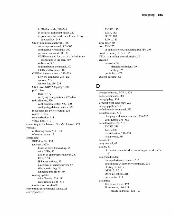
815
in NBMA mode, 240–241in point-to-multipoint mode, 242in point-to-point mode on a Frame Relay
subinterface, 243OSPF in multiarea networks, 300
area range command, 302–303configuring virtual links, 309network command, 300–301OSPF command for cost of a default route
propagated to the area, 307stub areas, 305summarization command, 303totally stubby areas, 306
OSPF on internal routers, 232–233network command, 233–235options, 235options for, 236–238
OSPF over NBMA topology, 240prefix lists
BGP-4, 472verifying configurations, 473–474
redistribution, 529configuration syntax, 529–530configuring default metrics, 531
route maps for policy routing, 554router ID, 236summarization, 111virtual links, 310
connecting to the Internet. See also Internet, 475contents
of Routing exam, 9–11, 13of routing exam, 12
controllingBGP-4 traffic, 470network traffic
Cisco express forwarding, 56with CPUs, 56design of client/server network, 57EIGRP, 58IP helper address, 57placement of clients/servers, 57silicon switching, 56tunneling into IP, 59–60
routing updateswith filtering, 539–541redistribution, 515–516
terminal access, 49–50conventions for command syntax, 21convergence, 181
EIGRP, 182IGRP, 182OSPF, 183RIPv1, 181
Core layer, 40cost, 236–237
of path selection, calculating (OSPF), 295count to infinity, RIPv1, 175CPUs, controlling network traffic, 56creating
networks, 38hierarchical designs, 39scaling, 39
prefix lists, 472custom queuing, 52
Ddebug command, BGP-4, 424debug commands, 380debug ip bgp, 424debug ip ospf adjacency, 220debug ip policy, 560default metric command, 532default metrics, 531
changing with cost command, 236-237configuring, 531–532
default routes, 162, 515EIGRP, 538IGRP, 538redistribution, 537–538when to use, 538
delays, 38deny any, 43, 47design, 39
of client server networks, controlling network traffic, 57
designated routersbackup designated routers, 216determining with priority command, 238electing, 217-219OSPF, 217-219OSPF neighbors, 216purpose for, 217
designingBGP-4 networks, 459IP networks, 116–121
private addresses, 122–123
designing
chpt_01.book Page 815 Thursday, December 21, 2000 6:22 PM
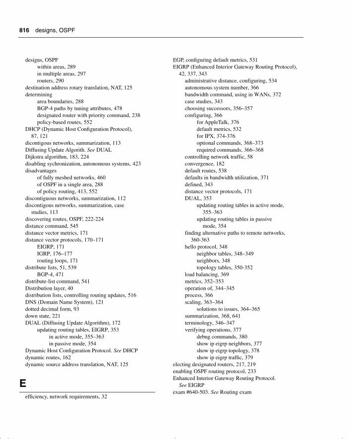
816
designs, OSPFwithin areas, 289in multiple areas, 297routers, 290
destination address rotary translation, NAT, 125determining
area boundaries, 288BGP-4 paths by tuning attributes, 478designated router with priority command, 238policy-based routes, 552
DHCP (Dynamic Host Configuration Protocol), 87, 121
dicontigous networks, summarization, 113Diffusing Update Algorith. See DUALDijkstra algorithm, 183, 224disabling sychronization, autonomous systems, 423disadvantages
of fully meshed networks, 460of OSPF in a single area, 288of policy routing, 413, 552
discontiguous networks, summarization, 112discontigous networks, summarization, case
studies, 113discovering routes, OSPF, 222-224distance command, 545distance vector metrics, 171distance vector protocols, 170–171
EIGRP, 171IGRP, 176–177routing loops, 171
distribute lists, 51, 539BGP-4, 471
distribute-list command, 541Distribution layer, 40distribution lists, controlling routing updates, 516DNS (Domain Name System), 121dotted decimal form, 93down state, 221DUAL (Diffusing Update Algorithm), 172
updating routing tables, EIGRP, 353in active mode, 355–363in passive mode, 354
Dynamic Host Configuration Protocol. See DHCPdynamic routes, 162dynamic source address translation, NAT, 125
Eefficiency, network requirements, 32
EGP, configuring default metrics, 531EIGRP (Enhanced Interior Gateway Routing Protocol),
42, 337, 343administrative distance, configuring, 534autonomous system number, 366bandwidth command, using in WANs, 372case studies, 343choosing successors, 356–357configuring, 366
for AppleTalk, 376default metrics, 532for IPX, 374-376optional commands, 368–373required commands, 366–368
controlling network traffic, 58convergence, 182default routes, 538defaults in bandwidth utilization, 371defined, 343distance vector protocols, 171DUAL, 353
updating routing tables in active mode, 355–363
updating routing tables in passive mode, 354
finding alternative paths to remote networks, 360-363
hello protocol, 348neighbor tables, 348–349neighbors, 348topology tables, 350-352
load balancing, 369metrics, 352–353operation of, 344–345process, 366scaling, 363–364
solutions to issues, 364–365summarization, 368, 641terminology, 346–347verifying operations, 377
debug commands, 380show ip eigrp neighbors, 377show ip eigrp topology, 378show ip eigrp traffic, 379
electing designated routers, 217, 219enabling OSPF routing protocol, 233Enhanced Interior Gateway Routing Protocol.
See EIGRPexam #640-503. See Routing exam
designs, OSPF
chpt_01.book Page 816 Thursday, December 21, 2000 6:22 PM
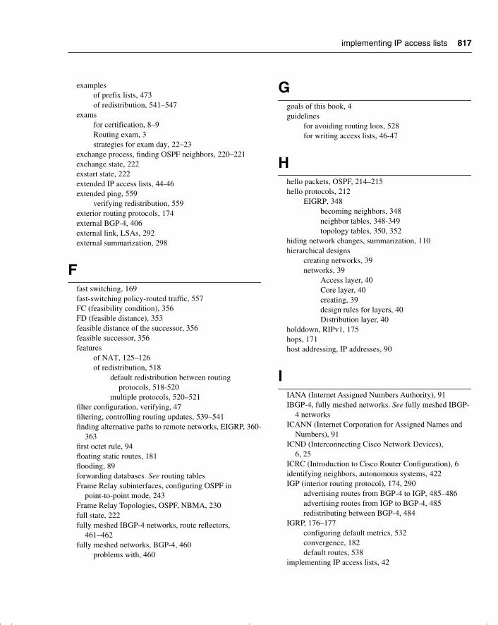
817
examplesof prefix lists, 473of redistribution, 541–547
examsfor certification, 8–9Routing exam, 3strategies for exam day, 22–23
exchange process, finding OSPF neighbors, 220–221exchange state, 222exstart state, 222extended IP access lists, 44-46extended ping, 559
verifying redistribution, 559exterior routing protocols, 174external BGP-4, 406external link, LSAs, 292external summarization, 298
Ffast switching, 169fast-switching policy-routed traffic, 557FC (feasibility condition), 356FD (feasible distance), 353feasible distance of the successor, 356feasible successor, 356features
of NAT, 125–126of redistribution, 518
default redistribution between routing protocols, 518-520
multiple protocols, 520–521filter configuration, verifying, 47filtering, controlling routing updates, 539–541finding alternative paths to remote networks, EIGRP, 360-
363first octet rule, 94floating static routes, 181flooding, 89forwarding databases. See routing tablesFrame Relay subinterfaces, configuring OSPF in
point-to-point mode, 243Frame Relay Topologies, OSPF, NBMA, 230full state, 222fully meshed IBGP-4 networks, route reflectors,
461–462fully meshed networks, BGP-4, 460
problems with, 460
Ggoals of this book, 4guidelines
for avoiding routing loos, 528for writing access lists, 46-47
Hhello packets, OSPF, 214–215hello protocols, 212
EIGRP, 348becoming neighbors, 348neighbor tables, 348-349topology tables, 350, 352
hiding network changes, summarization, 110hierarchical designs
creating networks, 39networks, 39
Access layer, 40Core layer, 40creating, 39design rules for layers, 40Distribution layer, 40
holddown, RIPv1, 175hops, 171host addressing, IP addresses, 90
IIANA (Internet Assigned Numbers Authority), 91IBGP-4, fully meshed networks. See fully meshed IBGP-
4 networksICANN (Internet Corporation for Assigned Names and
Numbers), 91ICND (Interconnecting Cisco Network Devices),
6, 25ICRC (Introduction to Cisco Router Configuration), 6identifying neighbors, autonomous systems, 422IGP (interior routing protocol), 174, 290
advertising routes from BGP-4 to IGP, 485–486advertising routes from IGP to BGP-4, 485redistributing between BGP-4, 484
IGRP, 176–177configuring default metrics, 532convergence, 182default routes, 538
implementing IP access lists, 42
implementing IP access lists
chpt_01.book Page 817 Thursday, December 21, 2000 6:22 PM

818
init state, 221interarea summarization, 298Interconnecting Cisco Network Devices. See ICNDInterconnecting Cisco Networking Devices, 6interdomain routing, 96interior routing protocol. See IGPintermittent activity, 38intermittent connectivity, 38internal BGP-4, 406internal router, 289Internet
IP addressing, 90-92, 97fixing problems with CIDR, 97
multiple connections, 475receiving routing information, 475–476
redundant connections to, 474Internet addresses, 90Internet Assigned Numbers Authority (IANA), 91Internet authoritative bodies, IP addresses, 91Internet Corporation for Assigned Names and Numbers
(ICANN), 91Internet mask, IP addresses, 90Introduction to Cisco Router Configuration (ICRC), 6IP
managing network congestion, 42tunneling into, controlling network traffic, 59–60
IP access lists, 41-43. See also access listsalleviating network congestion with Cisco
routers, 41extended IP access lists, 44-46implementing, 42standard IP access lists, 43–44uses of, 49
ip access-group, 43IP addresses, 89
address space, optimizing, 114-116and the Internet, 97
CIDR, 97bit allocation, 92classes, 91host addressing, 90Internet, 90-92Internet authoriative bodies, 91Internet masks, 90networks, 90subnet masks, 92, 96
logical AND, 93–94network boundaries, 92rules, 95
rules for IP subnetting, 94rules in IP subnetting, 94
subnetsrules, 95
IP addressing, summary of, 128ip classless command, 546ip forward-protocol, 58IP helper address, 58
controlling network traffic, 57IP networks, designing, 116–121
private addresses, 122–123ip ospf cost, 237ip ospf network, 240ip ospf network non-broadcast, 242IP subnetting, rules for, 94ip unnumbered, 111IP VLSM subnets, assigning to WAN connections, 114–
115IPX, configuring EIGRP for, 374-376is, 292ISP, connecting with alternative methods, 426–427
J-Kkeepalives, BGP-4 message types, 406
LLayer 3, definition of networks, 87Layer 3 addresses
definition, 87need for, 86-87network characteristics of, 88
layers, design rules for, 40links, 299. See also virtual linkslink-state advertisements (LSAs), 174, 291
OSPF, 291-292propagating, 292-293
link-state routing protocols, 172–173networks, 173path selection, 174updating local network tables, 174
LLQ (low-latency queuing), 53load balancing
EIGRP, 369RIPv1, 176
loading state, 222Local Preference, BGP-4 attributes, 416
init state
chpt_01.book Page 818 Thursday, December 21, 2000 6:22 PM
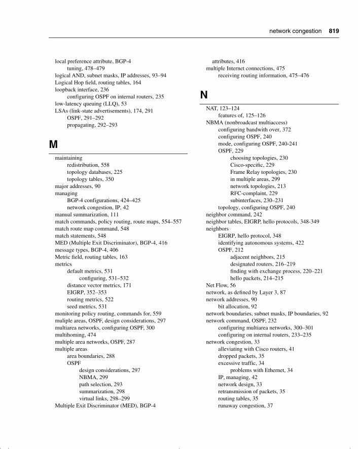
819
local preference attribute, BGP-4tuning, 478–479
logical AND, subnet masks, IP addresses, 93–94Logical Hop field, routing tables, 164loopback interface, 236
configuring OSPF on internal routers, 235low-latency queuing (LLQ), 53LSAs (link-state advertisements), 174, 291
OSPF, 291–292propagating, 292–293
Mmaintaining
redistribution, 558topology databases, 225topology tables, 350
major addresses, 90managing
BGP-4 configurations, 424–425network congestion, IP, 42
manual summarization, 111match commands, policy routing, route maps, 554–557match route map command, 548match statements, 548MED (Multiple Exit Discriminator), BGP-4, 416message types, BGP-4, 406Metric field, routing tables, 163metrics
default metrics, 531configuring, 531–532
distance vector metrics, 171EIGRP, 352–353routing metrics, 522seed metrics, 531
monitoring policy routing, commands for, 559muliple areas, OSPF, design considerations, 297multiarea networks, configuring OSPF, 300multihoming, 474multiple area networks, OSPF, 287multiple areas
area boundaries, 288OSPF
design considerations, 297NBMA, 299path selection, 293summarization, 298virtual links, 298–299
Multiple Exit Discriminator (MED), BGP-4
attributes, 416multiple Internet connections, 475
receiving routing information, 475–476
NNAT, 123–124
features of, 125–126NBMA (nonbroadcast multiaccess)
configuring bandwith over, 372configuring OSPF, 240mode, configuring OSPF, 240-241OSPF, 229
choosing topologies, 230Cisco-specific, 229Frame Relay topologies, 230in multiple areas, 299network topologies, 213RFC-complaint, 229subinterfaces, 230–231
topology, configuring OSPF, 240neighbor command, 242neighbor tables, EIGRP, hello protocols, 348-349neighbors
EIGRP, hello protocol, 348identifying autonomous systems, 422OSPF, 212
adjacent neighbors, 215designated routers, 216–219finding with exchange process, 220–221hello packets, 214–215
Net Flow, 56network, as defined by Layer 3, 87network addresses, 90
bit allocation, 92network boundaries, subnet masks, IP boundaries, 92network command, OSPF, 232
configuring multiarea networks, 300–301configuring on internal routers, 233–235
network congestion, 33alleviating with Cisco routers, 41dropped packets, 35excessive traffic, 34
problems with Ethernet, 34IP, managing, 42network design, 33retransmission of packets, 35routing tables, 35runaway congestion, 37
network congestion
chpt_01.book Page 819 Thursday, December 21, 2000 6:22 PM
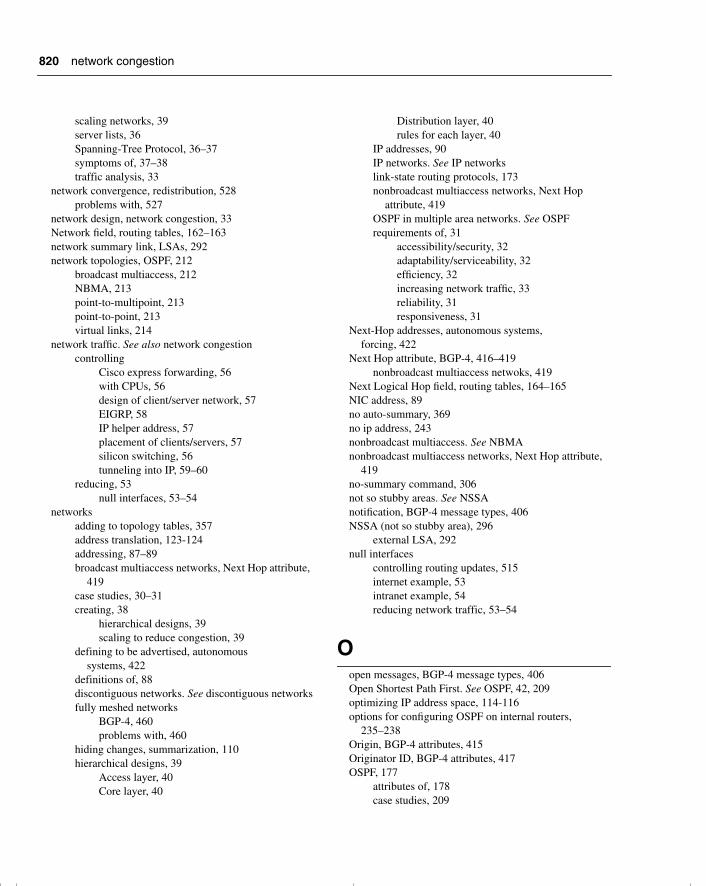
820
scaling networks, 39server lists, 36Spanning-Tree Protocol, 36–37symptoms of, 37–38traffic analysis, 33
network convergence, redistribution, 528problems with, 527
network design, network congestion, 33Network field, routing tables, 162–163network summary link, LSAs, 292network topologies, OSPF, 212
broadcast multiaccess, 212NBMA, 213point-to-multipoint, 213point-to-point, 213virtual links, 214
network traffic. See also network congestioncontrolling
Cisco express forwarding, 56with CPUs, 56design of client/server network, 57EIGRP, 58IP helper address, 57placement of clients/servers, 57silicon switching, 56tunneling into IP, 59–60
reducing, 53null interfaces, 53–54
networksadding to topology tables, 357address translation, 123-124addressing, 87–89broadcast multiaccess networks, Next Hop attribute,
419case studies, 30–31creating, 38
hierarchical designs, 39scaling to reduce congestion, 39
defining to be advertised, autonomous systems, 422
definitions of, 88discontiguous networks. See discontiguous networksfully meshed networks
BGP-4, 460problems with, 460
hiding changes, summarization, 110hierarchical designs, 39
Access layer, 40Core layer, 40
Distribution layer, 40rules for each layer, 40
IP addresses, 90IP networks. See IP networkslink-state routing protocols, 173nonbroadcast multiaccess networks, Next Hop
attribute, 419OSPF in multiple area networks. See OSPFrequirements of, 31
accessibility/security, 32adaptability/serviceability, 32efficiency, 32increasing network traffic, 33reliability, 31responsiveness, 31
Next-Hop addresses, autonomous systems, forcing, 422
Next Hop attribute, BGP-4, 416–419nonbroadcast multiaccess netwoks, 419
Next Logical Hop field, routing tables, 164–165NIC address, 89no auto-summary, 369no ip address, 243nonbroadcast multiaccess. See NBMAnonbroadcast multiaccess networks, Next Hop attribute,
419no-summary command, 306not so stubby areas. See NSSAnotification, BGP-4 message types, 406NSSA (not so stubby area), 296
external LSA, 292null interfaces
controlling routing updates, 515internet example, 53intranet example, 54reducing network traffic, 53–54
Oopen messages, BGP-4 message types, 406Open Shortest Path First. See OSPF, 42, 209optimizing IP address space, 114-116options for configuring OSPF on internal routers,
235–238Origin, BGP-4 attributes, 415Originator ID, BGP-4 attributes, 417OSPF, 177
attributes of, 178case studies, 209
network congestion
chpt_01.book Page 820 Thursday, December 21, 2000 6:22 PM
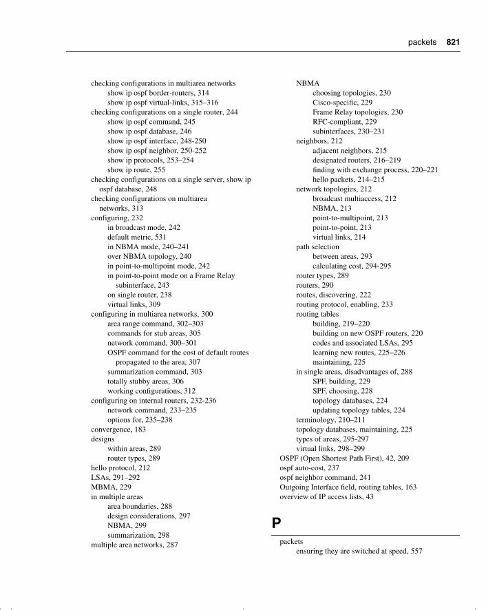
821
checking configurations in multiarea networksshow ip ospf border-routers, 314show ip ospf virtual-links, 315–316
checking configurations on a single router, 244show ip ospf command, 245show ip ospf database, 246show ip ospf interface, 248-250show ip ospf neighbor, 250-252show ip protocols, 253–254show ip route, 255
checking configurations on a single server, show ip ospf database, 248
checking configurations on multiarea networks, 313
configuring, 232in broadcast mode, 242default metric, 531in NBMA mode, 240–241over NBMA topology, 240in point-to-multipoint mode, 242in point-to-point mode on a Frame Relay
subinterface, 243on single router, 238virtual links, 309
configuring in multiarea networks, 300area range command, 302–303commands for stub areas, 305network command, 300–301OSPF command for the cost of default routes
propagated to the area, 307summarization command, 303totally stubby areas, 306working configurations, 312
configuring on internal routers, 232-236network command, 233–235options for, 235–238
convergence, 183designs
within areas, 289router types, 289
hello protocol, 212LSAs, 291–292MBMA, 229in multiple areas
area boundaries, 288design considerations, 297NBMA, 299summarization, 298
multiple area networks, 287
NBMAchoosing topologies, 230Cisco-specific, 229Frame Relay topologies, 230RFC-compliant, 229subinterfaces, 230–231
neighbors, 212adjacent neighbors, 215designated routers, 216–219finding with exchange process, 220–221hello packets, 214–215
network topologies, 212broadcast multiaccess, 212NBMA, 213point-to-multipoint, 213point-to-point, 213virtual links, 214
path selectionbetween areas, 293calculating cost, 294-295
router types, 289routers, 290routes, discovering, 222routing protocol, enabling, 233routing tables
building, 219–220building on new OSPF routers, 220codes and associated LSAs, 295learning new routes, 225–226maintaining, 225
in single areas, disadvantages of, 288SPF, building, 229SPF, choosing, 228topology databases, 224updating topology tables, 224
terminology, 210–211topology databases, maintaining, 225types of areas, 295-297virtual links, 298–299
OSPF (Open Shortest Path First), 42, 209ospf auto-cost, 237ospf neighbor command, 241Outgoing Interface field, routing tables, 163overview of IP access lists, 43
Ppackets
ensuring they are switched at speed, 557
packets
chpt_01.book Page 821 Thursday, December 21, 2000 6:22 PM
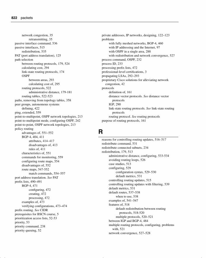
822
network congestion, 35retransmitting, 35
passive interface command, 536passive interfaces, 515
redistribution, 535PAT (port address translation), 125path selection
between routing protocols, 179, 524calculating cost, 294link-state routing protocols, 174OSPF
between areas, 293calculating cost of, 295
routing protocols, 522administrative distance, 179-181
routing tables, 522-523paths, removing from topology tables, 358peer groups, autonomous systems
defining, 422ping, extended, 559point-to-multipoint, OSPF network topologies, 213point-to-multipoint mode, configuring OSPF, 242point-to-point, OSPF network topologies, 213policy routing
advantages of, 551–552BGP-4, 404, 411
attributes, 414–417disadvantages of, 413rules of, 411
characteristics of, 551commands for monitoring, 559configuring route maps, 554disadvantages of, 552route maps, 547-552
match commands, 554–557port address translation. See PATprefix lists, 490–491
BGP-4, 471configuring, 472creating, 472processing, 472
examples of, 473verifying configurations, 473–474
prefix routing. See CIDRprerequisites for BSCN course, 5prioritization access lists, 52-53priority, 53priority command, 238priority queuing, 52
private addresses, IP networks, designing, 122–123problems
with fully meshed networks, BGP-4, 460with IP addressing and the Internet, 97with OSPF in a single area, 288with redistribution and network convergence, 527
process command, OSPF, 232process ID, 233processing prefix lists, 472professional-level certifications, 3propagating LSAs, 292–293proprietary Cisco solutions for alleviating network
congestion, 42protocols
definition of, 161distance vector protocols. See distance vector
protocolsIGP, 290link-state routing protocols. See link-state routing
protocolsrouting protocol. See routing protocols
purpose of routing protocols, 161
Rreasons for controlling routing updates, 516–517redistribute command, 531redistribute connected subnets, 234redistribution, 179, 513
administrative distance, configuring, 533-534avoiding routing loops, 526case studies, 513configuring, 529
configuration syntax, 529–530default metrics, 531
controlling routing updates, 515controlling routing updates with filtering, 539default metrics, 531default routes, 537–538
when to use, 538examples of, 541–547features of, 518
default redistribution between routing protocols, 518-520
multiple protocols, 520–521between IGP and BGP-4, 484multiple routing protocols, configuring, problems
with, 521network convergence, 527–528
packets
chpt_01.book Page 822 Thursday, December 21, 2000 6:22 PM

823
passive interfaces, 535path selection
between routing protocols, 524within routing protocols, 522
reasons for using on routing protocol, 521between routing protocols, 513-515routing updates, controlling, 516seed metrics, 531static routes, 535–537verifying, 558
extended ping, 559traceroute, 558
reducingnetwork traffic, 53
null interfaces, 53–54size of routing tables, summarization, 110
reliability, network requirements, 31remote networks, finding alternative paths to, EIGRP,
360-363removing paths or routers from topology tables, 358requirements of networks, 31–32
accessibility/security, 32efficiency, 32increasing network traffic, 33reliability, 31responsiveness, 31
responsiveness, requirements of networks, 31RFC-compliant, NBMA, 229RIP, configuring default metrics, 531RIPv1 (Routing Information Protocol version 1),
175-176convergence, 181
route aggregation, BGP-4, 410–411route-map command, 549route map command syntax, 549route maps
BGP-4, 471characteristics of, 548–549controlling routing updates, 516policy routing, 547-552
match commands, 554–557statements, 553uses for, 548
route reflectors, 489–490characteristics of, 463–464fully meshed IBGP-4 networks, 461–462rules for propagating updates, 464–470
route selection, BGP-4, 419-421route switching, 557
routed protocols versus routing protocols, 161–162router ID, 233
configuring, 236configuring OSPF on internal routers, 235
router link, LSAs, 291router ospf process number, 233routers. See also Cisco routers
designated routersOSPF, 216OSPF neighbors, 217-219
OSPF, 289–290removing from topology tables, 358types, OSPF, 289
routesautonomous systems, aggregating, 423OSPF, discovering, 222-224
routingpolicy-based routing. See policy-based routingSIN routing, 518versus switching, 167
Routing 2.0 exam. See Routing examRouting and Switching career tracks, 7Routing exam, 3–4
contents of, 9–13routing function, 167Routing Information Protocol version 1. See RIPv1routing loops, 171
avoiding, 528avoiding when redistributing, 526
routing metrics, 522routing protocols
case studies, 160definition of, 161exterior routing protocols, 174IGRP, 176–177interior routing protocols, 174link-state routing protocols. See link-state routing
protocolsOSPF, 177
attributes of, 178enabling, 233
path selection, 522administrative distance, 179-181
path selection between, 179, 524purpose of, 161redistribution, 513-515RIPv1, 175–176types of, 169
classful routing protocols, 169
routing protocols
chpt_01.book Page 823 Thursday, December 21, 2000 6:22 PM
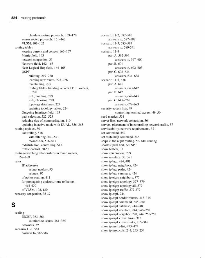
824
classless routing protocols, 169–170versus routed protocols, 161–162VLSM, 101–102
routing tableskeeping current and correct, 166–167Metric field, 163network congestion, 35Network field, 162–163Next Logical Hop field, 164–165OSPF
building, 219–220learning new routes, 225–226maintaining, 225routing tables, building on new OSPF routers,
220SPF, building, 229SPF, choosing, 228topology databases, 224updating topology tables, 224
Outgoing Interface field, 163path selection, 522–523reducing size of, summarization, 110updating in active mode with DUAL, 356–363
routing updates, 50controlling, 516
with filtering, 540–541reasons for, 516–517
redistribution, controlling, 515traffic control, 50-52
routing/switching relationships in Cisco routers, 168–169
rulesIP addresses
subnet maskes, 95subnets, 95
of policy routing, 411for propagating updates, route reflectors,
464-470of VLSM, 102, 130
runaway congestion, 35-37
Sscaling
EIGRP, 363–364solutions to issues, 364–365
networks, 39scenario 11-1, 581
answers to, 585-587
scenario 11-2, 582–583answers to, 587–588
scenario 11-3, 583–584answers to, 589-591
scenario 11-4part A, 592-596
answers to, 597–600part B, 601
answers to, 602–603part C, 603–634
answers, 634–638scenario 11-5, 638
part A, 640answers, 640–642
part B, 642answers, 642–645
part C, 645–679answers, 679–683
security access lists, 49controlling terminal access, 49–50
seed metrics, 531server lists, network congestion, 36servers, placement of in controlling network traffic, 57serviceability, network requirements, 32set command, 552set route map command, 548ships in the night routing. See SIN routingshortest path first. See SPFshow buffers, 33show cpu process, 289show interface, 33, 371show ip bgp, 424, 481show ip bgp neighbors, 424show ip bgp paths, 424show ip bgp summary, 424show ip eigrp neighbors, 377show ip eigrp topology, 377–379show ip eigrp topology all, 377show ip eigrp traffic, 377-379show ip ospf, 244show ip ospf border-routers, 313–315show ip ospf command, 245–246show ip ospf database, 244-248show ip ospf interface, 244, 248–250show ip ospf neighbor, 220, 244, 250-252show ip ospf virtual links, 313show ip ospf virtual-links, 315–316show ip prefix-list, 473–474show ip protocols, 244, 253–254
routing protocols
chpt_01.book Page 824 Thursday, December 21, 2000 6:22 PM
825
show ip route, 165–166, 244, 255show ip route eigrp, 380show ipx route, 377show memory, 289show queuing, 33silicon switching, 56, 169SIN (ships in the night) routing, 518Spanning-Tree Protocol, network congestion, 36–37SPF (shortest path first), 224
building routing tables, 228-229split horizon, 175
RIPv1, 175with poison reverse, 175split horizon rule, 171
starting routing processes, autonomous systems, 422statements, route maps, 553static addressing, NAT, 125static routes, 162, 515
redistribution, 535–537default routes, 537–538
VLSM, 102stop telnet, 46strategies for exam day, 22–23stub areas, 296
OSPF commands, 305–306stubby areas, 296studying
how to study with this book if you haven’t taken the BSCN, 20
how to study with this book if you’ve taken the Cisco Networking Academy courses, 19
how to use this book, 15–17if you’ve taken the ACRC, 18if you’ve taken the Cisco Networking Academy
courses, 18how to use this book if you haven’t taken the BSCN,
19sub net zero, 105subinterfaces
configuring OSPF in point-to-point mode, 243OSPF
NBMA, 230–231subnet masks
IP addresses, 92, 96logical AND, 93–94network boundaries, 92rules, 95rules for IP subnetting, 94rules in IP subnetting, 94
VLSM. See VLSM, 101subnet rule, 105subnets
IP addressesrules, 95
successorschoosing, 357
EIGRP, 356summaries
IP addressing, 128of CIDR, 128
summarization, 107address exhaustion, 111advantages of, 110, 130alternatives to, 113automatic summarization, 111configuring, 111discontiguous networks, 112–113
case studies, 113EIGRP, 368in EIGRP, 641IP address space, optimizing, 114-116manual summarization, 111OSPF in multiple areas, 298
summarization command, 303summary-only command, 423supernet addresses, 90supernets, 107switching function, 168switching versus routing, 167symptoms of network congestion, 37–38synchronization
autonomous systems, disabling, 423BGP-4, 408
syntax of route map command, 549
Tterminal access, controlling, 49–50terminology, EIGRP, 346–347topologies, OSPF, NBMA, 230topology databases
maintaining, 225OSPF, building routing tables, 224
topology tables, 349adding to networks, 357EIGRP, hello protocol, 350-352maintaining, 350OSPF, routing tables, 224
topology tables
chpt_01.book Page 825 Thursday, December 21, 2000 6:22 PM
826
removing paths or routers, 358totally stubby areas, OSPF commands, 306–307trace, 559traceroute, redistribution, verifying, 558traffic
controlling in BGP-4, 470network congestion, 34route switching, 557
traffic analysis, network congestion, 33traffic control, routing updates, 50-52translating addresses, 123–124triggered updates
with poison reverse, 181RIPv1, 175
troubleshooting, redistribution, 558tunnel interface, 61tunneling into IP, controlling network traffic, 59–60two-way state, 221types
of areas, OSPF, 295-297of routing protocols, 169
classful routing protocols, 169classless routing protocols, 169–170
Uunderruns, 616update messages, BGP-4 message types, 406updates, route reflectors, rules for propagating updates,
464–470updating
local network tables, link-state routing protocols, 174
routing tables, 166–167in active mode with DUAL, 355–363in passive mode with DUAL, 354
Vvariable-length subnet masks. See VLSMvariance command, 369-371verifying
BGP-4 attribute configurations, 481-484BGP-4 configurations, 424–425EIGRP operations, 377
debug commands, 380show ip eigrp neighbors, 377show ip eigrp topology, 378
show ip eigrp traffic, 379filter configuration, 47prefix lists configurations, 473–474redistribution, 558
extended ping, 559traceroute, 558
VIPs (Versatile Interface Processors), 56virtual links
configuring, 310OSPF
in multiarea networks, configuring, 309in multiple areas, 298–299network topologies, 214
virtual terminal line, 49VLANs, 87VLSM (variable-length subnet masks), 101
advantages of, 102allocating VLSM addresses, 105–106bit allocation, 105
case studies, 103–105example of, 101routing protocols, 101rules for, 102, 130static routes, 102
VLSM addresses, allocating, 105–106vty (virtual terminal line), 49
commands, 50
W-ZWAN connections, IP VLSM subnets, assigning,
114–115WANs, bandwith command and EIGRP, 372Weight, BGP-4 attributes, 417weight attribute, BGP-4, tuning, 478writing access lists, guidelines for, 46–47
totally stubby areas, OSPF commands
chpt_01.book Page 826 Thursday, December 21, 2000 6:22 PM


![CCNP Routing and Switching TSHOOT 300-135 …...[ iv ] CCNP Routing and Switching TSHOOT 300-135 Quick Reference About the Author Brent Stewart, CCNP, CCDP, CCSI, MCSE, is the vice](https://img.dokumen.tips/doc/110x75/5f10b1cc7e708231d44a5dc3/ccnp-routing-and-switching-tshoot-300-135-iv-ccnp-routing-and-switching.jpg)