Embed Size (px)
Citation preview
Cisco ASR 1001-X Router Hardware Installation Guide
July 28, 2014
Cisco Systems, Inc.www.cisco.com
Cisco has more than 200 offices worldwide. Addresses, phone numbers, and fax numbers are listed on the Cisco website at www.cisco.com/go/offices.
Text Part Number: OL-32376-03
THE SPECIFICATIONS AND INFORMATION REGARDING THE PRODUCTS IN THIS MANUAL ARE SUBJECT TO CHANGE WITHOUT NOTICE. ALL STATEMENTS, INFORMATION, AND RECOMMENDATIONS IN THIS MANUAL ARE BELIEVED TO BE ACCURATE BUT ARE PRESENTED WITHOUT WARRANTY OF ANY KIND, EXPRESS OR IMPLIED. USERS MUST TAKE FULL RESPONSIBILITY FOR THEIR APPLICATION OF ANY PRODUCTS.
THE SOFTWARE LICENSE AND LIMITED WARRANTY FOR THE ACCOMPANYING PRODUCT ARE SET FORTH IN THE INFORMATION PACKET THAT SHIPPED WITH THE PRODUCT AND ARE INCORPORATED HEREIN BY THIS REFERENCE. IF YOU ARE UNABLE TO LOCATE THE SOFTWARE LICENSE OR LIMITED WARRANTY, CONTACT YOUR CISCO REPRESENTATIVE FOR A COPY.
The following information is for FCC compliance of Class A devices: This equipment has been tested and found to comply with the limits for a Class A digital device, pursuant to part 15 of the FCC rules. These limits are designed to provide reasonable protection against harmful interference when the equipment is operated in a commercial environment. This equipment generates, uses, and can radiate radio-frequency energy and, if not installed and used in accordance with the instruction manual, may cause harmful interference to radio communications. Operation of this equipment in a residential area is likely to cause harmful interference, in which case users will be required to correct the interference at their own expense.
The following information is for FCC compliance of Class B devices: This equipment has been tested and found to comply with the limits for a Class B digital device, pursuant to part 15 of the FCC rules. These limits are designed to provide reasonable protection against harmful interference in a residential installation. This equipment generates, uses and can radiate radio frequency energy and, if not installed and used in accordance with the instructions, may cause harmful interference to radio communications. However, there is no guarantee that interference will not occur in a particular installation. If the equipment causes interference to radio or television reception, which can be determined by turning the equipment off and on, users are encouraged to try to correct the interference by using one or more of the following measures:
• Reorient or relocate the receiving antenna.
• Increase the separation between the equipment and receiver.
• Connect the equipment into an outlet on a circuit different from that to which the receiver is connected.
• Consult the dealer or an experienced radio/TV technician for help.
Modifications to this product not authorized by Cisco could void the FCC approval and negate your authority to operate the product.
The Cisco implementation of TCP header compression is an adaptation of a program developed by the University of California, Berkeley (UCB) as part of UCB’s public domain version of the UNIX operating system. All rights reserved. Copyright © 1981, Regents of the University of California.
NOTWITHSTANDING ANY OTHER WARRANTY HEREIN, ALL DOCUMENT FILES AND SOFTWARE OF THESE SUPPLIERS ARE PROVIDED “AS IS” WITH ALL FAULTS. CISCO AND THE ABOVE-NAMED SUPPLIERS DISCLAIM ALL WARRANTIES, EXPRESSED OR IMPLIED, INCLUDING, WITHOUT LIMITATION, THOSE OF MERCHANTABILITY, FITNESS FOR A PARTICULAR PURPOSE AND NONINFRINGEMENT OR ARISING FROM A COURSE OF DEALING, USAGE, OR TRADE PRACTICE.
IN NO EVENT SHALL CISCO OR ITS SUPPLIERS BE LIABLE FOR ANY INDIRECT, SPECIAL, CONSEQUENTIAL, OR INCIDENTAL DAMAGES, INCLUDING, WITHOUT LIMITATION, LOST PROFITS OR LOSS OR DAMAGE TO DATA ARISING OUT OF THE USE OR INABILITY TO USE THIS MANUAL, EVEN IF CISCO OR ITS SUPPLIERS HAVE BEEN ADVISED OF THE POSSIBILITY OF SUCH DAMAGES.
Cisco and the Cisco logo are trademarks or registered trademarks of Cisco and/or its affiliates in the U.S. and other countries. To view a list of Cisco trademarks, go to this URL: www.cisco.com/go/trademarks. Third-party trademarks mentioned are the property of their respective owners. The use of the word partner does not imply a partnership relationship between Cisco and any other company. (1110R)
Any Internet Protocol (IP) addresses and phone numbers used in this document are not intended to be actual addresses and phone numbers. Any examples, command display output, network topology diagrams, and other figures included in the document are shown for illustrative purposes only. Any use of actual IP addresses or phone numbers in illustrative content is unintentional and coincidental.
Cisco ASR 1001-X Router Hardware Installation Guide© 2014 Cisco Systems, Inc. All rights reserved.
OL-32376-03
C O N T E N T S
Preface ix
Document Revision History ix
Document Objectives ix
Audience x
Document Organization x
Conventions xi
Safety Warnings and Cautions xi
Warning Definition xii
Obtaining Documentation and Submitting a Service Request xvii
Cisco ASR 1001-X Router Overview 1-1
Hardware Features of the Cisco ASR 1001-X Router 1-1
Cisco ASR 1001-X Overall Chassis Front View 1-2
Cisco ASR 1001-X Router LEDs 1-3
Cisco ASR 1001-X Management Storage Connections 1-3
Cisco ASR 1001-X Chassis Rear View 1-4
Cisco ASR 1001-X SPA GE and TE Ports 1-5
Field-Replaceable Units for the Cisco ASR 1001-X Router 1-5
Cisco Product Identification Standard 1-6
Unique Device Identifier 1-6
SPA Slot Numbering 1-7
Serial Number and PID/VID Label Location 1-8
Cisco ASR 1001-X Router Supported Hardware Components 2-1
Supported Hardware Components 2-1
Supported Half-Height SPAs 2-2
Supported Small Form-Factor Pluggable (SFP and SFP+) Transceivers 2-3
Supported NIMs 2-4
NIM-SSD 2-4
NIM-T1/E1 2-4
Cisco ASR 1001-X Router Power Supplies 2-5
Power Supplies for the Cisco ASR 1001-X Router 2-5
Cisco ASR 1001-X Power Supply Fans 2-6
Cisco ASR 1001-X Router AC Power Supply 2-6
iiiCisco ASR 1001-X Router Hardware Installation Guide
Contents
Cisco ASR 1001-X Router DC Power Supply 2-7
AC/DC Power System Input Range and Voltage for the Cisco ASR 1001-X Router 2-8
Power Cords Supported by the Cisco ASR 1001-X Router 2-8
Preparing Your Site for Installation 3-1
Prerequisites and Preparation 3-1
Site Planning Checklist 3-2
Safety Guidelines 3-2
Safety Warnings 3-2
Safety Recommendations 3-3
Compliance Requirements 3-3
Cautions and Regulatory Compliance Statements for NEBS 3-4
Standard Warning Statements 3-5
General Safety Warnings 3-5
Site Planning 3-8
General Precautions 3-8
Site Selection Guidelines 3-9
Site Environmental Requirements 3-9
Physical Characteristics 3-10
Site Power Guidelines 3-11
Electrical Circuit Requirements 3-11
Site Cabling Guidelines 3-12
Console Port Connections 3-13
Interference Considerations 3-13
Rack-Mounting Guidelines 3-15
Precautions for Rack-Mounting 3-15
General Rack-Selection Guidelines 3-15
Guidelines for 23-in. (Telco) Racks 3-16
Equipment Rack Guidelines 3-16
Preventing Electrostatic Discharge Damage 3-17
Electrical Safety 3-18
Chassis-Lifting Guidelines 3-18
Tools and Equipment 3-19
Unpacking and Verifying Shipping Contents 3-19
Checking the Shipping Container Contents 3-19
Cisco ASR 1001-X Router Installation Checklist 3-20
Cisco ASR 1001-X Router Installation 4-1
Installation Methods 4-1
ivCisco ASR 1001-X Router Hardware Installation Guide
OL-32376-03
Contents
Guidelines for a Standalone Equipment Shelf or Tabletop Installation 4-2
Steps for Installing the Cisco ASR 1001-X Router on a Standalone Equipment Shelf or Tabletop Installation 4-2
General Guidelines for Rack Installation 4-3
Rack-Mounting the Cisco ASR 1001-X Router 4-4
Verifying Rack Dimensions 4-4
Attaching the Chassis Rack-Mount Brackets 4-5
Chassis Front Rack-Mount Brackets 4-5
Mounting the Cisco ASR 1001-X Router in the Rack 4-6
Two-Post Rack Installation 4-6
Four-Post Rack Installation 4-8
Attaching the Cable Management Bracket 4-9
Attaching a Chassis Ground Connection 4-10
Recommended Tools and Supplies 4-10
Connecting Cables 4-12
Connecting the Console and Auxiliary Port Cables 4-12
Connecting to the Mini USB Console Port 4-13
Management Ethernet Port Cable Connection 4-14
Connecting the Built-in 1 GE SFP and 10 GE SFP+ Port Cables 4-14
Built-in 1 Gigabit Ethernet Port 4-14
Built-in 10 Gigabit Ethernet Port 4-14
Connecting the Shared Port Adapter Cables 4-15
Cisco ASR 1001-X Router Power Up and Initial Configuration 5-1
Checking Conditions Prior to System Startup 5-1
Powering Up the Cisco ASR 1001-X Router 5-2
Performing the Initial Configuration on the Router 5-4
Using the Cisco setup Command Facility 5-4
Completing the Configuration 5-7
Using the Cisco IOS-XE CLI—Manual Configuration 5-7
Configuring the Router Hostname 5-8
Configuring the Enable and Enable Secret Passwords 5-8
Configuring the Console Idle Privileged EXEC Timeout 5-10
Gigabit Ethernet Management Interface Overview 5-11
Default Gigabit Ethernet Configuration 5-12
Configuring Gigabit Ethernet Interfaces 5-12
Saving Your Router Configuration 5-13
Verifying the Initial Configuration 5-14
Powering Off the Cisco ASR 1001-X Router Safely 5-14
vCisco ASR 1001-X Router Hardware Installation Guide
OL-32376-03
Contents
Environmental Monitoring and Reporting Functions 5-15
Cisco ASR1001-X Router Alarm Monitoring 5-16
Environmental Monitoring 5-16
Fan Failures 5-18
Reporting Functions 5-18
Cisco ASR 1001-X Router License Verification 6-1
Viewing the Cisco IOS License Level 6-1
Configuring the Throughput Level 6-2
Viewing License Information 6-3
Per Port Counted License (10-GE Interfaces) 6-7
10-GE Interface Evaluation License Features 6-9
Removing and Replacing FRUs from the Cisco ASR 1001-X Router 7-1
Removing and Replacing the Cisco ASR 1001-X Router Power Supplies 7-1
Removing AC Power Supplies from the Cisco ASR 1001-X Router 7-2
Installing AC Power Supplies in the Cisco ASR 1001-X Router 7-3
Removing DC Input Power from the Cisco ASR 1001-X Router 7-5
Installing DC Input Power on the Cisco ASR 1001-X Router 7-6
Wiring the DC Input Power Source 7-6
Removing and Replacing Cisco ASR 1001-X Router USB Flash Memory Stick or Secure Token 7-8
Removing and Replacing the Cisco ASR 1001-X Router DIMM 7-9
Removing and Replacing the Cisco ASR 1001-X Router DIMM Memory Module 7-9
Removing a Cisco ASR 1001-X Router DIMM 7-11
Replacing a Cisco ASR 1001-X Router DIMM 7-12
Removing and Replacing a Cisco ASR 1001-X Router SPA 7-14
Electrostatic Discharge Prevention 7-15
Removing a Shared Port Adapter 7-16
Replacing a Shared Port Adapter 7-16
Removing and Replacing a NIM on the Cisco ASR 1001-X Router 7-17
Removing a NIM 7-18
Replacing a NIM 7-18
Removing and Replacing an SSD from the NIM-SSD Module 7-19
Removing an SSD from the NIM-SSD Module 7-19
Installing an SSD into the NIM-SSD Module 7-21
Repacking the Router 7-22
Upgrading the ROMMON and CPLD 8-1
Upgrading the ROMMON 8-1
Compatibility Requirements 8-1
viCisco ASR 1001-X Router Hardware Installation Guide
OL-32376-03
Contents
Checking the Current ROMMON Version 8-1
Upgrading the ROMMON for the Cisco ASR 1001-X Router 8-2
Example: Upgrading a ROMMON 8-3
Compatible ROMMON Releases 8-5
Resolved Caveats 8-6
Hardware the Require a CPLD Upgrade 8-6
Upgrading the CPLD 8-6
Checking Hardware and Software Compatibility 8-7
Using Cisco Feature Navigator 8-7
Cisco ASR 1001-X Router Specifications A-1
Cisco ASR 1001-X Router Specifications A-1
Cisco ASR 1001-X Router Memory and Storage Options A-1
Cisco ASR 1001-X Router Signals and Pinouts B-1
Management Ethernet Port Signals and Pinouts B-1
Console Port Signals and Pinouts B-1
Auxiliary Port Signals and Pinouts B-2
viiCisco ASR 1001-X Router Hardware Installation Guide
OL-32376-03

Contents
viiiCisco ASR 1001-X Router Hardware Installation Guide
OL-32376-03
Preface
Revised: July 28, 2014, OL-32376-03
This preface describes the objectives and organization of this document and explains how to find additional information on related products and services, and contains the following sections:
• Document Revision History, page ix
• Document Objectives, page ix
• Audience, page x
• Document Organization, page x
• Conventions, page xi
• Safety Warnings and Cautions, page xi
• Obtaining Documentation and Submitting a Service Request, page xvii
Document Revision HistoryThe following table records the changes made to this document.
Document ObjectivesThis publication describes the installation of a Cisco ASR 1001-X Router and replacement or upgrade of field-replaceable units (FRUs).
Document Version Date Change Summary
OL-32376-03 July 2014 Updated for Cisco IOS XE Release 3.13.
OL-32376-02 June 2014 Updated for Cisco IOS XE Release 3.12.1.
OL-32376-01 June 2014 First version of the document.
ixCisco ASR 1001-X Router Hardware Installation Guide
OL-32376-03
AudienceThis publication is primarily designed for persons responsible for installing, maintaining, and troubleshooting the Cisco ASR 1001-X Router. The users of this guide should:
• Be familiar with electronic circuitry and wiring practices.
• Have experience working as electronic or electromechanical technicians.
• Have experience in installing high-end networking equipment.
Note Certain procedures described in this guide require a certified electrician.
Document OrganizationThe following table describes the chapters and appendixes in this installation guide:
Chapter and Appendix Description
Chapter 1, “Cisco ASR 1001-X Router Overview” This chapter provides an overview of the Cisco ASR 1001-X Router.
Chapter 2, “Cisco ASR 1001-X Router Supported Hardware Components”
This chapter provides an overview of the hardware components for the Cisco ASR 1001-X Router.
Chapter 3, “Preparing Your Site for Installation” This chapter provides site preparation guidelines for installing the Cisco ASR 1001-X Router.
Chapter 4, “Cisco ASR 1001-X Router Installation” This chapter provides information about the installation methods and steps to install the Cisco ASR 1001-X Router.
Chapter 5, “Cisco ASR 1001-X Router Power Up and Initial Configuration”
This chapter provides basic system startup and initial configuration information.
Chapter 6, “Cisco ASR 1001-X Router License Verification” This chapter provides information about the Cisco ASR 1001-X Router licenses.
Chapter 7, “Removing and Replacing FRUs from the Cisco ASR 1001-X Router”
This chapter provides instructions for removing and replacing the various FRUs in the Cisco ASR 1001-X Router.
Chapter 8, “Upgrading the ROMMON and CPLD” This chapter describes the procedures to upgrade the ROMmon on the Cisco ASR 1001-X Router.
Appendix A, “Cisco ASR 1001-X Router Specifications” This appendix provides router specifications for the Cisco ASR 1001-X Router.
Appendix B, “Cisco ASR 1001-X Router Signals and Pinouts” This appendix lists pinout specifications for the Cisco ASR 1001-X Router.
xCisco ASR 1001-X Router Hardware Installation Guide
OL-32376-03
ConventionsThis document uses the following conventions:
Note Means reader take note.
Tip Means the following information will help you solve a problem.
Caution Means reader be careful. In this situation, you might perform an action that could result in equipment damage or loss of data.
Timesaver Means the described action saves time. You can save time by performing the action described in the paragraph.
Safety Warnings and CautionsMost safety warnings for the Cisco ASR 1001-X Router are placed in relevant sections throughout the document. For translated safety warnings, see the Regulatory Compliance and Safety Information for the Cisco 1000 Series Aggregation Services Routers. Statement 1071, the Warning Definition statement, complete with translated warnings is provided in this section.
Convention Indication
bold font Commands, keywords, and text entered by users appear in bold font.
italic font Document titles, new or emphasized terms, and arguments for which you supply values are in italic font.
[ ] Elements in square brackets are optional.
{x | y | z } Required alternative keywords are grouped in braces and separated by vertical bars.
[ x | y | z ] Optional alternative keywords are grouped in brackets and separated by vertical bars.
string A nonquoted set of characters. Do not use quotation marks around the string or the string will include the quotation marks.
courier font Terminal sessions and information the system displays appear in courier font.
< > Nonprinting characters such as passwords are in angle brackets.
[ ] Default responses to system prompts are in square brackets.
!, # An exclamation point (!) or a pound sign (#) at the beginning of a line of code indicates a comment line.
xiCisco ASR 1001-X Router Hardware Installation Guide
OL-32376-03
Warning Definition
Warning IMPORTANT SAFETY INSTRUCTIONS
This warning symbol means danger. You are in a situation that could cause bodily injury. Before you work on any equipment, be aware of the hazards involved with electrical circuitry and be familiar with standard practices for preventing accidents. Use the statement number provided at the end of each warning to locate its translation in the translated safety warnings that accompanied this device. Statement 1071
SAVE THESE INSTRUCTIONS
Waarschuwing BELANGRIJKE VEILIGHEIDSINSTRUCTIES
Dit waarschuwingssymbool betekent gevaar. U verkeert in een situatie die lichamelijk letsel kan veroorzaken. Voordat u aan enige apparatuur gaat werken, dient u zich bewust te zijn van de bij elektrische schakelingen betrokken risico's en dient u op de hoogte te zijn van de standaard praktijken om ongelukken te voorkomen. Gebruik het nummer van de verklaring onderaan de waarschuwing als u een vertaling van de waarschuwing die bij het apparaat wordt geleverd, wilt raadplegen.
BEWAAR DEZE INSTRUCTIES
Varoitus TÄRKEITÄ TURVALLISUUSOHJEITA
Tämä varoitusmerkki merkitsee vaaraa. Tilanne voi aiheuttaa ruumiillisia vammoja. Ennen kuin käsittelet laitteistoa, huomioi sähköpiirien käsittelemiseen liittyvät riskit ja tutustu onnettomuuksien yleisiin ehkäisytapoihin. Turvallisuusvaroitusten käännökset löytyvät laitteen mukana toimitettujen käännettyjen turvallisuusvaroitusten joukosta varoitusten lopussa näkyvien lausuntonumeroiden avulla.
SÄILYTÄ NÄMÄ OHJEET
Attention IMPORTANTES INFORMATIONS DE SÉCURITÉ
Ce symbole d'avertissement indique un danger. Vous vous trouvez dans une situation pouvant entraîner des blessures ou des dommages corporels. Avant de travailler sur un équipement, soyez conscient des dangers liés aux circuits électriques et familiarisez-vous avec les procédures couramment utilisées pour éviter les accidents. Pour prendre connaissance des traductions des avertissements figurant dans les consignes de sécurité traduites qui accompagnent cet appareil, référez-vous au numéro de l'instruction situé à la fin de chaque avertissement.
CONSERVEZ CES INFORMATIONS
xiiCisco ASR 1001-X Router Hardware Installation Guide
OL-32376-03
Warnung WICHTIGE SICHERHEITSHINWEISE
Dieses Warnsymbol bedeutet Gefahr. Sie befinden sich in einer Situation, die zu Verletzungen führen kann. Machen Sie sich vor der Arbeit mit Geräten mit den Gefahren elektrischer Schaltungen und den üblichen Verfahren zur Vorbeugung vor Unfällen vertraut. Suchen Sie mit der am Ende jeder Warnung angegebenen Anweisungsnummer nach der jeweiligen Übersetzung in den übersetzten Sicherheitshinweisen, die zusammen mit diesem Gerät ausgeliefert wurden.
BEWAHREN SIE DIESE HINWEISE GUT AUF.
Avvertenza IMPORTANTI ISTRUZIONI SULLA SICUREZZA
Questo simbolo di avvertenza indica un pericolo. La situazione potrebbe causare infortuni alle persone. Prima di intervenire su qualsiasi apparecchiatura, occorre essere al corrente dei pericoli relativi ai circuiti elettrici e conoscere le procedure standard per la prevenzione di incidenti. Utilizzare il numero di istruzione presente alla fine di ciascuna avvertenza per individuare le traduzioni delle avvertenze riportate in questo documento.
CONSERVARE QUESTE ISTRUZIONI
Advarsel VIKTIGE SIKKERHETSINSTRUKSJONER
Dette advarselssymbolet betyr fare. Du er i en situasjon som kan føre til skade på person. Før du begynner å arbeide med noe av utstyret, må du være oppmerksom på farene forbundet med elektriske kretser, og kjenne til standardprosedyrer for å forhindre ulykker. Bruk nummeret i slutten av hver advarsel for å finne oversettelsen i de oversatte sikkerhetsadvarslene som fulgte med denne enheten.
TA VARE PÅ DISSE INSTRUKSJONENE
Aviso INSTRUÇÕES IMPORTANTES DE SEGURANÇA
Este símbolo de aviso significa perigo. Você está em uma situação que poderá ser causadora de lesões corporais. Antes de iniciar a utilização de qualquer equipamento, tenha conhecimento dos perigos envolvidos no manuseio de circuitos elétricos e familiarize-se com as práticas habituais de prevenção de acidentes. Utilize o número da instrução fornecido ao final de cada aviso para localizar sua tradução nos avisos de segurança traduzidos que acompanham este dispositivo.
GUARDE ESTAS INSTRUÇÕES
¡Advertencia! INSTRUCCIONES IMPORTANTES DE SEGURIDAD
Este símbolo de aviso indica peligro. Existe riesgo para su integridad física. Antes de manipular cualquier equipo, considere los riesgos de la corriente eléctrica y familiarícese con los procedimientos estándar de prevención de accidentes. Al final de cada advertencia encontrará el número que le ayudará a encontrar el texto traducido en el apartado de traducciones que acompaña a este dispositivo.
GUARDE ESTAS INSTRUCCIONES
xiiiCisco ASR 1001-X Router Hardware Installation Guide
OL-32376-03
Varning! VIKTIGA SÄKERHETSANVISNINGAR
Denna varningssignal signalerar fara. Du befinner dig i en situation som kan leda till personskada. Innan du utför arbete på någon utrustning måste du vara medveten om farorna med elkretsar och känna till vanliga förfaranden för att förebygga olyckor. Använd det nummer som finns i slutet av varje varning för att hitta dess översättning i de översatta säkerhetsvarningar som medföljer denna anordning.
SPARA DESSA ANVISNINGAR
xivCisco ASR 1001-X Router Hardware Installation Guide
OL-32376-03
Aviso INSTRUÇÕES IMPORTANTES DE SEGURANÇA
Este símbolo de aviso significa perigo. Você se encontra em uma situação em que há risco de lesões corporais. Antes de trabalhar com qualquer equipamento, esteja ciente dos riscos que envolvem os circuitos elétricos e familiarize-se com as práticas padrão de prevenção de acidentes. Use o número da declaração fornecido ao final de cada aviso para localizar sua tradução nos avisos de segurança traduzidos que acompanham o dispositivo.
GUARDE ESTAS INSTRUÇÕES
Advarsel VIGTIGE SIKKERHEDSANVISNINGER
Dette advarselssymbol betyder fare. Du befinder dig i en situation med risiko for legemesbeskadigelse. Før du begynder arbejde på udstyr, skal du være opmærksom på de involverede risici, der er ved elektriske kredsløb, og du skal sætte dig ind i standardprocedurer til undgåelse af ulykker. Brug erklæringsnummeret efter hver advarsel for at finde oversættelsen i de oversatte advarsler, der fulgte med denne enhed.
GEM DISSE ANVISNINGER
xvCisco ASR 1001-X Router Hardware Installation Guide
OL-32376-03
xviCisco ASR 1001-X Router Hardware Installation Guide
OL-32376-03
Warning Only trained and qualified personnel should be allowed to install, replace, or service this equipment. Statement 1030
Warning This unit is intended for installation in restricted access areas. A restricted access area can be accessed only through the use of a special tool, lock and key, or other means of security.Use when a product has an accessible HAZ/V circuits or a DC supply that is not provided with a field wiring cover. Statement 1017
Obtaining Documentation and Submitting a Service RequestFor information on obtaining documentation, submitting a service request, and gathering additional information, see the monthly What’s New in Cisco Product Documentation, which also lists all new and revised Cisco technical documentation, at:
http://www.cisco.com/en/US/docs/general/whatsnew/whatsnew.html
Subscribe to the What’s New in Cisco Product Documentation as a Really Simple Syndication (RSS) feed and set content to be delivered directly to your desktop using a reader application. The RSS feeds are a free service and Cisco currently supports RSS version 2.0.
xviiCisco ASR 1001-X Router Hardware Installation Guide
OL-32376-03

xviiiCisco ASR 1001-X Router Hardware Installation Guide
OL-32376-03
CisOL-32376-02
C H A P T E R 1
Cisco ASR 1001-X Router OverviewThe Cisco ASR 1000 Series Aggregation Services Routers are mid-range edge routers that establish a new price-to-performance class offering benefits to both enterprise and service providers alike. The Cisco ASR 1000 Series Aggregation Services Routers portfolio is based on an innovative custom-built ASIC called Quantum Flow Processor that aggregates services at scale.
The Cisco ASR 1001-X Router is a part of the Cisco ASR 1000 Series and offers a compact form factor that consumes less rack space and power while offering 20 Gbps forwarding throughput. The Cisco ASR 1001-X Router supports all the general-purpose routing and security features of the Cisco ASR 1000 Series Aggregation Services Routers.
Hardware Features of the Cisco ASR 1001-X RouterThe Cisco ASR 1001-X Router supports:
• Up to 16 GB (8 GB in the base configuration) of DDR3 error-correcting code-protected field- replaceable memory, with single-bit error correction and multi-bit error detection.
• A nonmodular and fixed Embedded Services Processor (ESP) with a default throughput of 2.5 Gbps that is upgradable with a software-activated performance license of 5 Gbps, 10 Gbps, or 20 Gbps.
• Up to 8 Gbps security and crypto processing through a dedicated security processor.
• RJ-45 console ports and auxiliary ports, and a mini USB console port.
• One copper Ethernet 10/100/1000 Mbps network management port.
• An embedded USB (eUSB) flash module that supports 8 GB of nonvolatile Flash storage.
• Two USB 2.0 ports for USB flash sticks or USB secure tokens (secure key distribution).
• Stratum 3E network clocking per GR-1244-CORE, using 1588, 10 GE, GE, SPA, or Network Interface Module (NIM) interfaces as timing sources.
• Six built-in 1 GE SFP-only interfaces (do not support SFP+), and two built-in 10 GE SFP+ interfaces (support only 10-GE rate) that support SyncE.
• One half-height SPA bay.
• Software redundancy using Dual IOS, similar to all the other nonhardware redundant routers from the Cisco ASR 1000 Series Aggregation Services Router family.
• LED indicators for Ethernet and console status, as well as visual system state indications.
• Command-line interface (CLI), alarm, network management, logging, statistics aggregation, and on-board failure logging (OBFL).
1-1co ASR 1001-X Router Hardware Installation Guide
Chapter 1 Cisco ASR 1001-X Router OverviewHardware Features of the Cisco ASR 1001-X Router
• Environmental chassis management.
• 10 MB ternary content-addressable memory (TCAM).
• Up to 20 Gbps sustained forwarding data traffic through the chassis.
• One Network Interface Module (NIM) bay.
Note The NIM bay supports the T1/E1 NIMs and the Solid State Device (SSD) NIM assembly and drive.
• Field-replaceable units (FRU) with online insertion and removal (OIR).
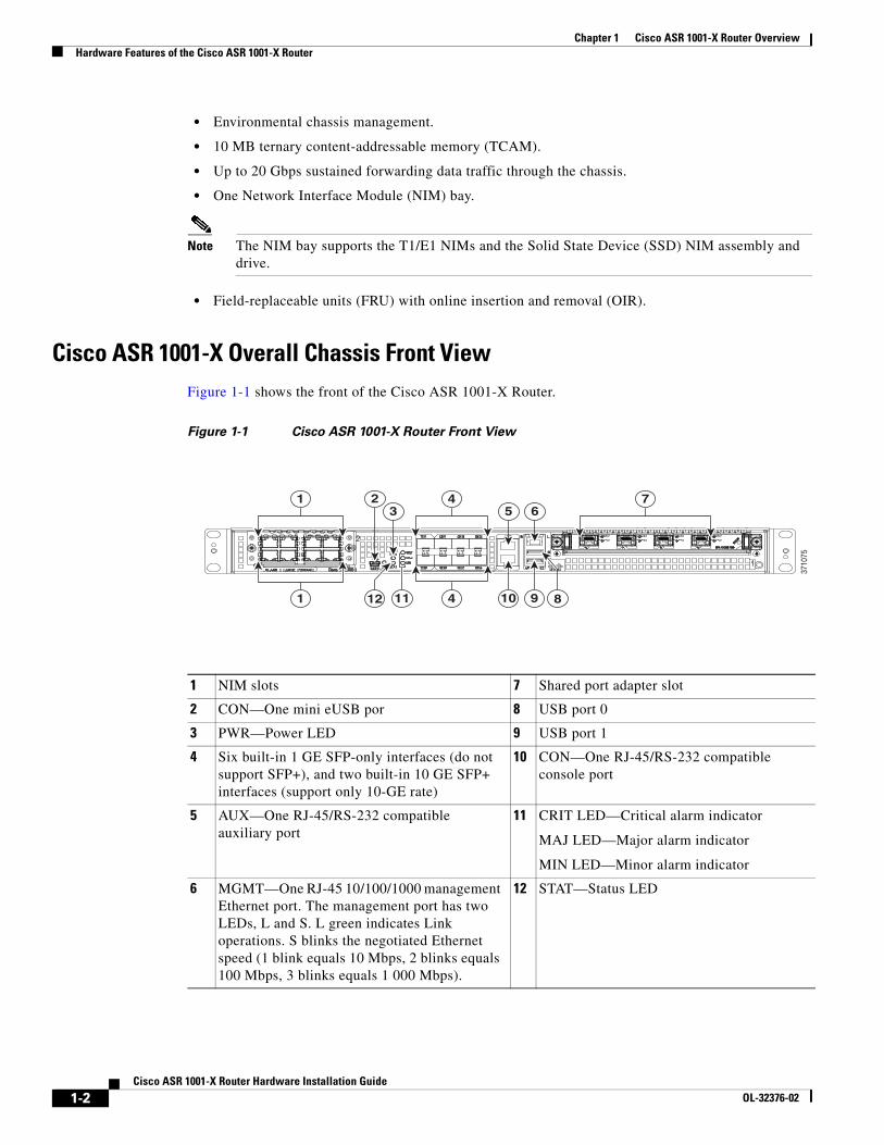
Cisco ASR 1001-X Overall Chassis Front ViewFigure 1-1 shows the front of the Cisco ASR 1001-X Router.
Figure 1-1 Cisco ASR 1001-X Router Front View
1 4 723 5 6
41 1112 810 9
3710
75
1 NIM slots 7 Shared port adapter slot
2 CON—One mini eUSB por 8 USB port 0
3 PWR—Power LED 9 USB port 1
4 Six built-in 1 GE SFP-only interfaces (do not support SFP+), and two built-in 10 GE SFP+ interfaces (support only 10-GE rate)
10 CON—One RJ-45/RS-232 compatible console port
5 AUX—One RJ-45/RS-232 compatible auxiliary port
11 CRIT LED—Critical alarm indicator
MAJ LED—Major alarm indicator
MIN LED—Minor alarm indicator
6 MGMT—One RJ-45 10/100/1000 management Ethernet port. The management port has two LEDs, L and S. L green indicates Link operations. S blinks the negotiated Ethernet speed (1 blink equals 10 Mbps, 2 blinks equals 100 Mbps, 3 blinks equals 1 000 Mbps).
12 STAT—Status LED
1-2Cisco ASR 1001-X Router Hardware Installation Guide
OL-32376-02
Chapter 1 Cisco ASR 1001-X Router OverviewHardware Features of the Cisco ASR 1001-X Router
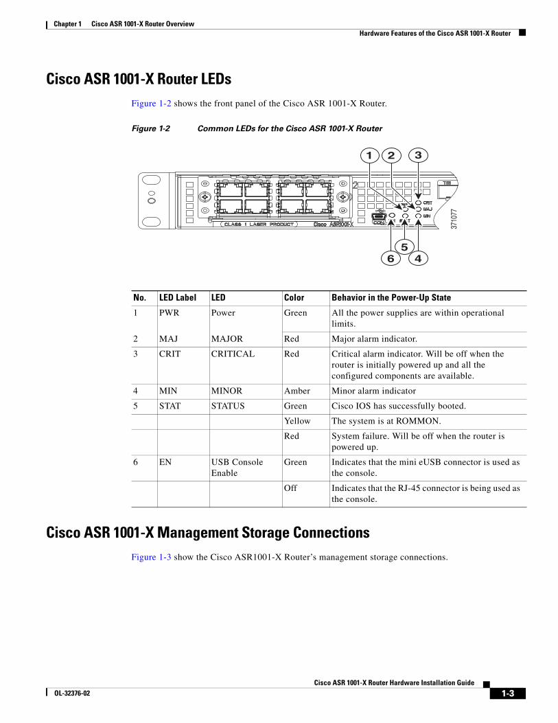
Cisco ASR 1001-X Router LEDsFigure 1-2 shows the front panel of the Cisco ASR 1001-X Router.
Figure 1-2 Common LEDs for the Cisco ASR 1001-X Router
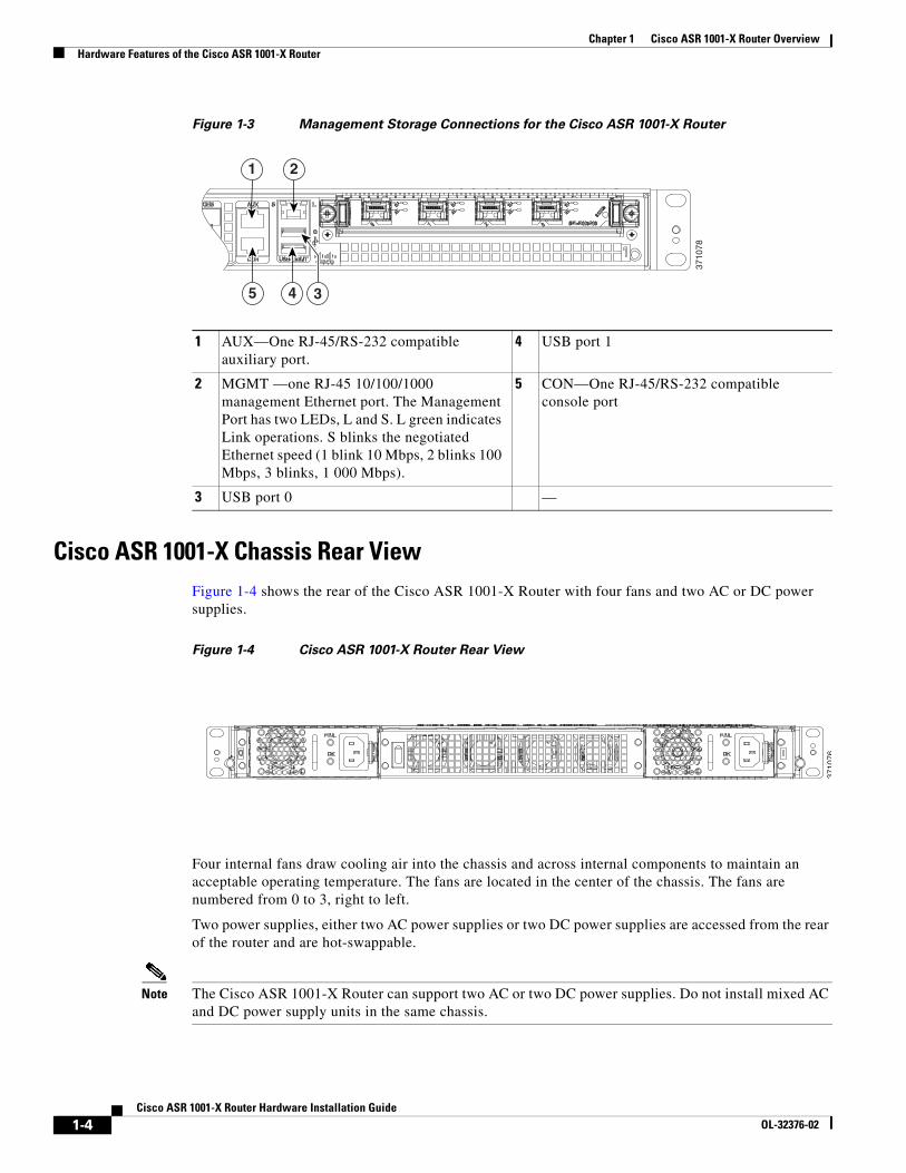
Cisco ASR 1001-X Management Storage ConnectionsFigure 1-3 show the Cisco ASR1001-X Router’s management storage connections.
3710
77
321
465
No. LED Label LED Color Behavior in the Power-Up State
1 PWR Power Green All the power supplies are within operational limits.
2 MAJ MAJOR Red Major alarm indicator.
3 CRIT CRITICAL Red Critical alarm indicator. Will be off when the router is initially powered up and all the configured components are available.
4 MIN MINOR Amber Minor alarm indicator
5 STAT STATUS Green Cisco IOS has successfully booted.
Yellow The system is at ROMMON.
Red System failure. Will be off when the router is powered up.
6 EN USB Console Enable
Green Indicates that the mini eUSB connector is used as the console.
Off Indicates that the RJ-45 connector is being used as the console.
1-3Cisco ASR 1001-X Router Hardware Installation Guide
OL-32376-02
Chapter 1 Cisco ASR 1001-X Router OverviewHardware Features of the Cisco ASR 1001-X Router
Figure 1-3 Management Storage Connections for the Cisco ASR 1001-X Router
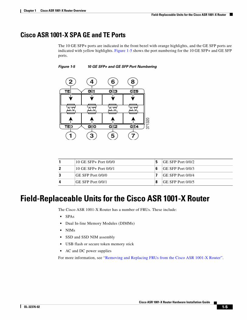
Cisco ASR 1001-X Chassis Rear ViewFigure 1-4 shows the rear of the Cisco ASR 1001-X Router with four fans and two AC or DC power supplies.
Figure 1-4 Cisco ASR 1001-X Router Rear View
Four internal fans draw cooling air into the chassis and across internal components to maintain an acceptable operating temperature. The fans are located in the center of the chassis. The fans are numbered from 0 to 3, right to left.
Two power supplies, either two AC power supplies or two DC power supplies are accessed from the rear of the router and are hot-swappable.
Note The Cisco ASR 1001-X Router can support two AC or two DC power supplies. Do not install mixed AC and DC power supply units in the same chassis.
1 AUX—One RJ-45/RS-232 compatible auxiliary port.
4 USB port 1
2 MGMT —one RJ-45 10/100/1000 management Ethernet port. The Management Port has two LEDs, L and S. L green indicates Link operations. S blinks the negotiated Ethernet speed (1 blink 10 Mbps, 2 blinks 100 Mbps, 3 blinks, 1 000 Mbps).
5 CON—One RJ-45/RS-232 compatible console port
3 USB port 0 —
1 2
35 4
3710
78
3710
76
1-4Cisco ASR 1001-X Router Hardware Installation Guide
OL-32376-02
Chapter 1 Cisco ASR 1001-X Router OverviewField-Replaceable Units for the Cisco ASR 1001-X Router
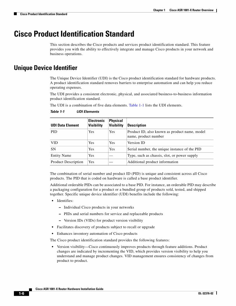
Cisco ASR 1001-X SPA GE and TE PortsThe 10 GE SFP+ ports are indicated in the front bezel with orange highlights, and the GE SFP ports are indicated with yellow highlights. Figure 1-5 shows the port numbering for the 10 GE SFP+ and GE SFP ports.
Figure 1-5 10 GE SFP+ and GE SFP Port Numbering
Field-Replaceable Units for the Cisco ASR 1001-X RouterThe Cisco ASR 1001-X Router has a number of FRUs. These include:
• SPAs
• Dual In-line Memory Modules (DIMMs)
• NIMs
• SSD and SSD NIM assembly
• USB flash or secure token memory stick
• AC and DC power supplies
For more information, see “Removing and Replacing FRUs from the Cisco ASR 1001-X Router”.
2 4 6 8
1 3 5 7
3713
20
1 10 GE SFP+ Port 0/0/0 5 GE SFP Port 0/0/2
2 10 GE SFP+ Port 0/0/1 6 GE SFP Port 0/0/3
3 GE SFP Port 0/0/0 7 GE SFP Port 0/0/4
4 GE SFP Port 0/0/1 8 GE SFP Port 0/0/5
1-5Cisco ASR 1001-X Router Hardware Installation Guide
OL-32376-02
Chapter 1 Cisco ASR 1001-X Router OverviewCisco Product Identification Standard
Cisco Product Identification StandardThis section describes the Cisco products and services product identification standard. This feature provides you with the ability to effectively integrate and manage Cisco products in your network and business operations.
Unique Device IdentifierThe Unique Device Identifier (UDI) is the Cisco product identification standard for hardware products. A product identification standard removes barriers to enterprise automation and can help you reduce operating expenses.
The UDI provides a consistent electronic, physical, and associated business-to-business information product identification standard.
The UDI is a combination of five data elements. Table 1-1 lists the UDI elements.
The combination of serial number and product ID (PID) is unique and consistent across all Cisco products. The PID that is coded on hardware is called a base product identifier.
Additional orderable PIDs can be associated to a base PID. For instance, an orderable PID may describe a packaging configuration for a product or a bundled group of products sold, tested, and shipped together. Specific unique device identifier (UDI) benefits include the following:
• Identifies:
– Individual Cisco products in your networks
– PIDs and serial numbers for service and replaceable products
– Version IDs (VIDs) for product version visibility
• Facilitates discovery of products subject to recall or upgrade
• Enhances inventory automation of Cisco products
The Cisco product identification standard provides the following features:
• Version visibility—Cisco continuously improves products through feature additions. Product changes are indicated by incrementing the VID, which provides version visibility to help you understand and manage product changes. VID management ensures consistency of changes from product to product.
Table 1-1 UDI Elements
UDI Data ElementElectronic Visibility
Physical Visibility Description
PID Yes Yes Product ID, also known as product name, model name, product number
VID Yes Yes Version ID
SN Yes Yes Serial number, the unique instance of the PID
Entity Name Yes — Type, such as chassis, slot, or power supply
Product Description Yes — Additional product information
1-6Cisco ASR 1001-X Router Hardware Installation Guide
OL-32376-02
Chapter 1 Cisco ASR 1001-X Router OverviewSPA Slot Numbering
• Operating expense reduction—Cisco UDIs provide accurate and detailed network inventory information; identifying each Cisco product in a network element through a standard interface. Cisco operating systems can view and use this data, allowing you to automate your electronic inventory.
• Consistency across product layers—The UDIs are embedded in the hardware products and cannot be overwritten. Operating and management systems discover UDIs through standard interfaces and display UDIs in standard outputs. Standard interfaces include the IETF standard ENTITY-MIB.
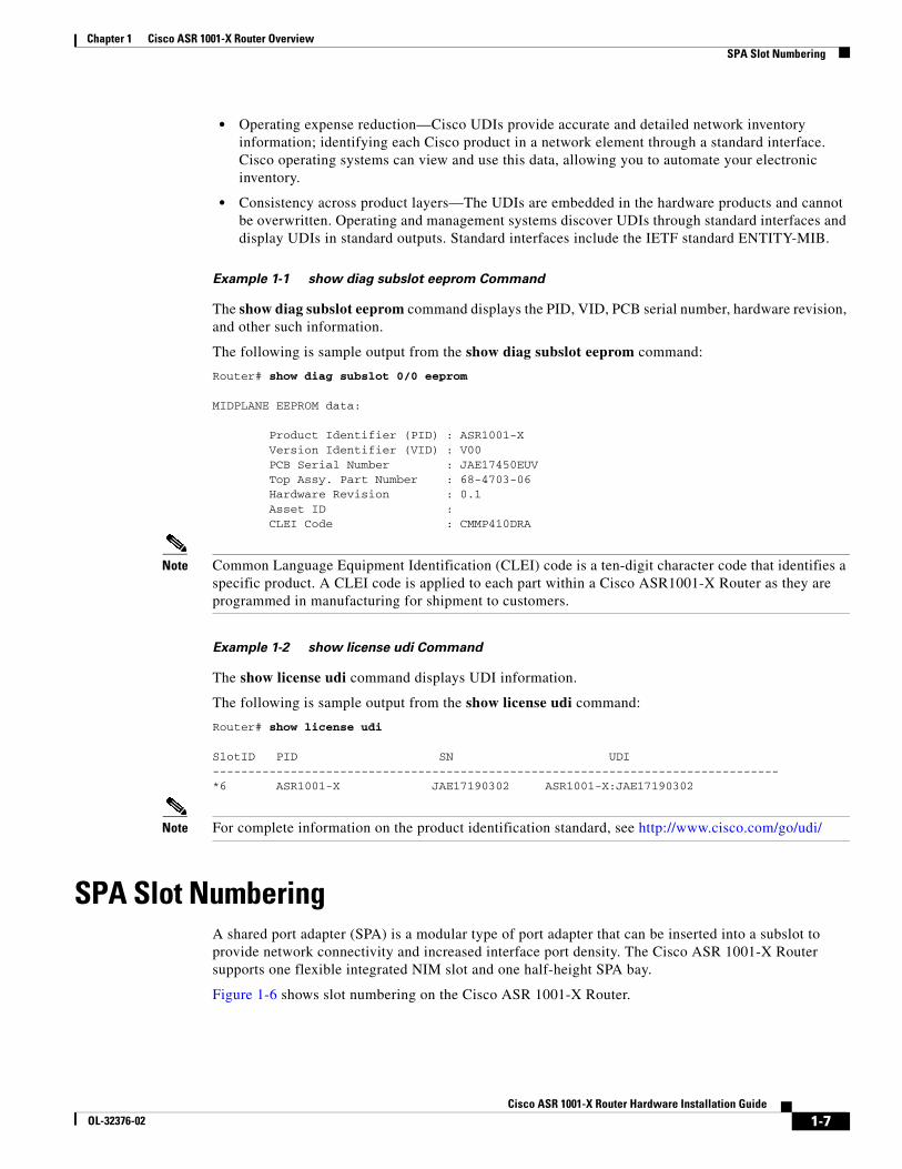
Example 1-1 show diag subslot eeprom Command
The show diag subslot eeprom command displays the PID, VID, PCB serial number, hardware revision, and other such information.
The following is sample output from the show diag subslot eeprom command:
Router# show diag subslot 0/0 eeprom
MIDPLANE EEPROM data:
Product Identifier (PID) : ASR1001-X Version Identifier (VID) : V00 PCB Serial Number : JAE17450EUV Top Assy. Part Number : 68-4703-06 Hardware Revision : 0.1 Asset ID : CLEI Code : CMMP410DRA
Note Common Language Equipment Identification (CLEI) code is a ten-digit character code that identifies a specific product. A CLEI code is applied to each part within a Cisco ASR1001-X Router as they are programmed in manufacturing for shipment to customers.
Example 1-2 show license udi Command
The show license udi command displays UDI information.
The following is sample output from the show license udi command:
Router# show license udi
SlotID PID SN UDI--------------------------------------------------------------------------------*6 ASR1001-X JAE17190302 ASR1001-X:JAE17190302
Note For complete information on the product identification standard, see http://www.cisco.com/go/udi/
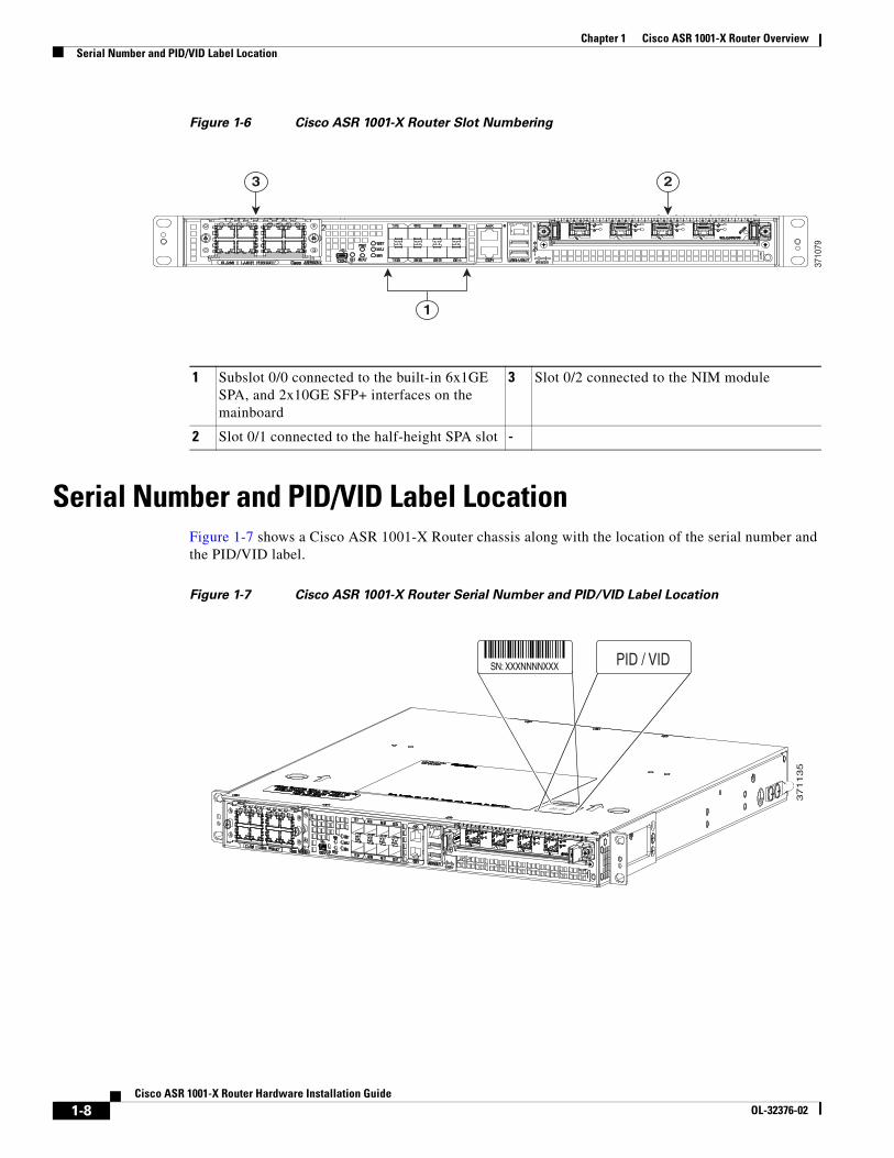
SPA Slot NumberingA shared port adapter (SPA) is a modular type of port adapter that can be inserted into a subslot to provide network connectivity and increased interface port density. The Cisco ASR 1001-X Router supports one flexible integrated NIM slot and one half-height SPA bay.
Figure 1-6 shows slot numbering on the Cisco ASR 1001-X Router.
1-7Cisco ASR 1001-X Router Hardware Installation Guide
OL-32376-02
Chapter 1 Cisco ASR 1001-X Router OverviewSerial Number and PID/VID Label Location
Figure 1-6 Cisco ASR 1001-X Router Slot Numbering
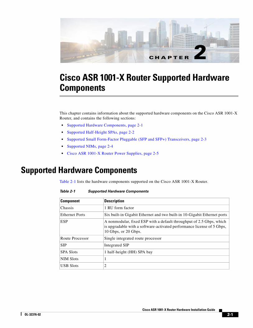
Serial Number and PID/VID Label LocationFigure 1-7 shows a Cisco ASR 1001-X Router chassis along with the location of the serial number and the PID/VID label.
Figure 1-7 Cisco ASR 1001-X Router Serial Number and PID/VID Label Location
3 2
1
3710
79
1 Subslot 0/0 connected to the built-in 6x1GE SPA, and 2x10GE SFP+ interfaces on the mainboard
3 Slot 0/2 connected to the NIM module
2 Slot 0/1 connected to the half-height SPA slot -
37
11
35
PID / VID
SN: XXXNNNNXXX PID / VID
1-8Cisco ASR 1001-X Router Hardware Installation Guide
OL-32376-02
CisOL-32376-02
C H A P T E R 2
Cisco ASR 1001-X Router Supported Hardware ComponentsThis chapter contains information about the supported hardware components on the Cisco ASR 1001-X Router, and contains the following sections:
• Supported Hardware Components, page 2-1
• Supported Half-Height SPAs, page 2-2
• Supported Small Form-Factor Pluggable (SFP and SFP+) Transceivers, page 2-3
• Supported NIMs, page 2-4
• Cisco ASR 1001-X Router Power Supplies, page 2-5
Supported Hardware ComponentsTable 2-1 lists the hardware components supported on the Cisco ASR 1001-X Router.
Table 2-1 Supported Hardware Components
Component Description
Chassis 1 RU form factor
Ethernet Ports Six built-in Gigabit Ethernet and two built-in 10-Gigabit Ethernet ports
ESP A nonmodular, fixed ESP with a default throughput of 2.5 Gbps, which is upgradable with a software-activated performance license of 5 Gbps, 10 Gbps, or 20 Gbps.
Route Processor Single integrated route processor
SIP Integrated SIP
SPA Slots 1 half-height (HH) SPA bay
NIM Slots 1
USB Slots 2
2-1co ASR 1001-X Router Hardware Installation Guide
Chapter 2 Cisco ASR 1001-X Router Supported Hardware ComponentsSupported Half-Height SPAs
Supported Half-Height SPAsTable 2-1 lists the supported half-height SPAs on the Cisco ASR 1001-X Router.Supported Half-Height SPAs
Table 2-2 Supported Half-Height SPAs
PID Description
SPA-1X10GE-L-V2 Cisco 1-Port 10GE LAN-PHY
SPA-1XCHSTM1/OC3 1-port Channelized STM-1/OC-3c to DS0
SPA-1XOC12-POS 1-port OC12/STM4 POS
SPA-2XOC12-POS 2-port OC12/STM4 POS
SPA-4XOC12-POS 4-port OC-12/STM-4 POS
SPA-8XOC12-POS 8-port OC12/STM4
SPA-1XOC3-ATM-V2 1-port OC-3c/STM-1 ATM
SPA-2X1GE-V2 Cisco 2-Port Gigabit Ethernet
SPA-2XCT3/DS0 2-port Channelized T3 to DS0
SPA-2XOC3-POS 2-port OC3/STM1 POS
SPA-8XOC3-POS 8-port OC-3/STM-1 POS
SPA-1XOC48POS/RPR 1-port OC48/STM16 POS/RPR
SPA-2XOC48POS/RPR 2-port OC48/STM16 POS/RPR
SPA-2XT3/E3 2-port Clear Channel T3/E3
SPA-3XOC3-ATM-V2 3-port OC-3c/STM-1 ATM
SPA-4X1FE-TX-V2 Cisco 4-Port Fast Ethernet (TX)
SPA-4XCT3/DS0 4-port Channelized T3 to DS0
SPA-4XOC3-POS 4-port OC3/STM1 POS
SPA-4XOC48POS/RPR 4-port OC48/STM16 POS/RPR Shared Port Adapters
SPA-OC192POS-XFP 1-port OC192/STM64 POS/RPR XFP Optics
SPA-4XT-SERIAL Cisco 4-port serial SPA
SPA-4XT3/E3 4-port Clear Channel T3/E3
SPA-5X1GE-V2 Cisco 5-Port Gigabit Ethernet
SPA-8X1FE-TX-V2 Cisco 8-Port Fast Ethernet (TX)
SPA-8X1GE-V2 Cisco 8-Port Gigabit Ethernet
SPA-8XCHT1/E1 8-port Channelized T1/E1 to DS0
SPA-1XOC12-ATM-V2 1-port OC12 STM
SPA-DSP Digital Signal Processor SPA
SPA-1X10GE-WL-V2 Cisco 1-port 10GE LAN/WAN-PHY
SPA-2CHT3-CE-ATM 2-Port Channelized T3/E3 ATM and Circuit Emulation SPA
2-2Cisco ASR 1001-X Router Hardware Installation Guide
OL-32376-02
Chapter 2 Cisco ASR 1001-X Router Supported Hardware ComponentsSupported Small Form-Factor Pluggable (SFP and SFP+) Transceivers
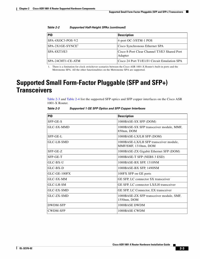
Supported Small Form-Factor Pluggable (SFP and SFP+) Transceivers
Table 2-3 and Table 2-4 list the supported SFP optics and SFP copper interfaces on the Cisco ASR 1001-X Router.
SPA-4XOC3-POS-V2 4-port OC-3/STM-1 POS
SPA-2X1GE-SYNCE1 Cisco Synchronous Ethernet SPA
SPA-8XT3/E3 Cisco 8-Port Clear Channel T3/E3 Shared Port Adapter
SPA-24CHT1-CE-ATM Cisco 24 Port T1/E1/J1 Circuit Emulation SPA
1. There is a limitation for clock switchover scenarios between the Cisco ASR 1001-X Router's built-in ports and the Metronome SPA. All the other functionalities on the Metronome SPA are supported.
Table 2-2 Supported Half-Height SPAs (continued)
PID Description
Table 2-3 Supported 1 GE SFP Optics and SFP Copper Interfaces
PID Description
SFP-GE-S 1000BASE-SX SFP (DOM)
GLC-SX-MMD 1000BASE-SX SFP transceiver module, MMF, 850nm, DOM
SFP-GE-L 1000BASE-LX/LH SFP (DOM)
GLC-LH-SMD 1000BASE-LX/LH SFP transceiver module, MMF/SMF, 1310nm, DOM
SFP-GE-Z 1000BASE-ZX Gigabit Ethernet SFP (DOM)
SFP-GE-T 1000BASE-T SFP (NEBS 3 ESD)
GLC-BX-U 1000BASE-BX SFP, 1310NM
GLC-BX-D 1000BASE-BX SFP, 1490NM
GLC-GE-100FX 100FX SFP on GE ports
GLC-SX-MM GE SFP, LC connector SX transceiver
GLC-LH-SM GE SFP, LC connector LX/LH transceiver
GLC-EX-SMD GE SFP, LC Connector, EX transceiver
GLC-ZX-SMD 1000BASE-ZX SFP transceiver module, SMF, 1550nm, DOM
DWDM-SFP 1000BASE DWDM
CWDM-SFP 1000BASE CWDM
2-3Cisco ASR 1001-X Router Hardware Installation Guide
OL-32376-02
Chapter 2 Cisco ASR 1001-X Router Supported Hardware ComponentsSupported NIMs
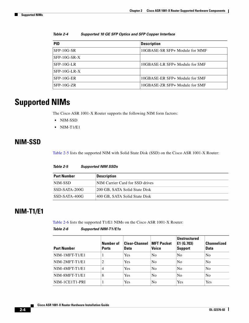
Supported NIMsThe Cisco ASR 1001-X Router supports the following NIM form factors:
• NIM-SSD
• NIM-T1/E1
NIM-SSDTable 2-5 lists the supported NIM with Solid State Disk (SSD) on the Cisco ASR 1001-X Router:
NIM-T1/E1Table 2-6 lists the supported T1/E1 NIMs on the Cisco ASR 1001-X Router:
Table 2-4 Supported 10 GE SFP Optics and SFP Copper Interface
PID Description
SFP-10G-SR 10GBASE-SR SFP+ Module for MMF
SFP-10G-SR-X
SFP-10G-LR 10GBASE-LR SFP+ Module for SMF
SFP-10G-LR-X
SFP-10G-ER 10GBASE-ER SFP+ Module for SMF
SFP-10G-ZR 10GBASE-ZR SFP+ Module for SMF
Table 2-5 Supported NIM SSDs
Part Number Description
NIM-SSD NIM Carrier Card for SSD drives
SSD-SATA-200G 200 GB, SATA Solid State Disk
SSD-SATA-400G 400 GB, SATA Solid State Disk
Table 2-6 Supported NIM-T1/E1s
Part NumberNumber of Ports
Clear-Channel Data
MFT Packet Voice
Unstructured E1 (G.703) Support
Channelized Data
NIM-1MFT-T1/E1 1 Yes No No No
NIM-2MFT-T1/E1 2 Yes No No No
NIM-4MFT-T1/E1 4 Yes No No No
NIM-8MFT-T1/E1 8 Yes No No No
NIM-1CE1T1-PRI 1 Yes No Yes Yes
2-4Cisco ASR 1001-X Router Hardware Installation Guide
OL-32376-02
Chapter 2 Cisco ASR 1001-X Router Supported Hardware ComponentsCisco ASR 1001-X Router Power Supplies
Cisco ASR 1001-X Router Power SuppliesThe Cisco ASR 1001-X Router supports AC and DC power supply options. The modular chassis configurations support the installation of two power supplies for redundancy. When an external power supply fails or is removed, the other power supply provides power requirements for the chassis. This allows you to hot-swap the power supply without impacting the functionality of the router.
Power Supplies for the Cisco ASR 1001-X RouterEach Cisco ASR 1001-X Router power supply provides 250 W of output power. The power supplies are used in a 1 + 1 redundant configuration. There is no input switch on the faceplate of the power supplies. A power supply is switched from Standby to On by way of a system chassis STANDBY/ON switch. When facing the rear of the chassis, power supply slot 0 (PS0) is to the left (next to the power supply standby switch) and power supply slot 1(PS1) is to the right.
The Cisco ASR 1001-X Router supports the following power supplies:
• Cisco ASR 1001-X Router AC power supply—Provides 250 W output power with DC voltage output of +12 V. The AC power supply operates between +85 and +264 VAC. The AC power supply current shares on the 12 V output and is used in a dual hot pluggable configuration.
• Cisco ASR 1001-X Router DC power supply—Provides 242 W output power with DC voltage output of +12 V. The power supply operates between –40 and –72 VDC. The DC power supply current shares on the 12 V output and is used in a dual hot-pluggable configuration.
Note The Cisco ASR 1001-X Router can support two AC or two DC power supplies. Do not install mixed AC and DC power supply units in the same chassis.
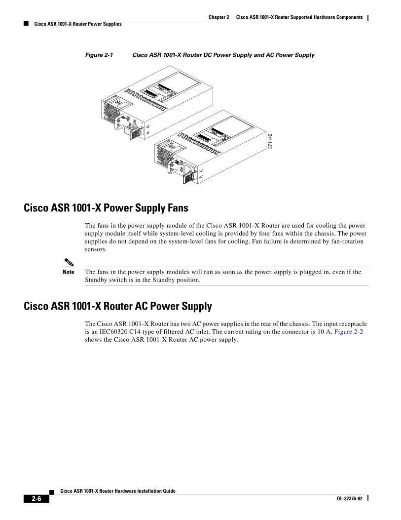
Figure 2-1 shows both the DC and AC power supplies for the Cisco ASR 1001-X Router.
NIM-2CE1T1-PRI 2 Yes No Yes Yes
NIM-8CE1T1-PRI 8 Yes No Yes Yes
Table 2-6 Supported NIM-T1/E1s (continued)
Part NumberNumber of Ports
Clear-Channel Data
MFT Packet Voice
Unstructured E1 (G.703) Support
Channelized Data
2-5Cisco ASR 1001-X Router Hardware Installation Guide
OL-32376-02
Chapter 2 Cisco ASR 1001-X Router Supported Hardware ComponentsCisco ASR 1001-X Router Power Supplies
Figure 2-1 Cisco ASR 1001-X Router DC Power Supply and AC Power Supply
Cisco ASR 1001-X Power Supply FansThe fans in the power supply module of the Cisco ASR 1001-X Router are used for cooling the power supply module itself while system-level cooling is provided by four fans within the chassis. The power supplies do not depend on the system-level fans for cooling. Fan failure is determined by fan-rotation sensors.
Note The fans in the power supply modules will run as soon as the power supply is plugged in, even if the Standby switch is in the Standby position.
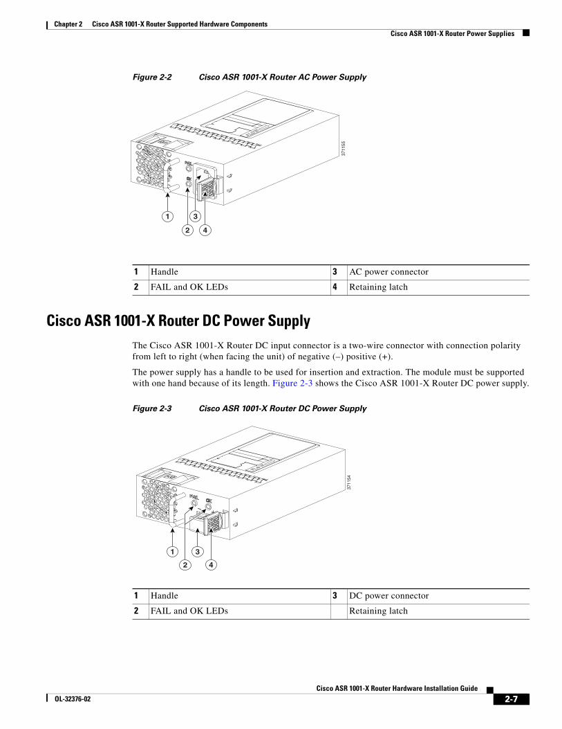
Cisco ASR 1001-X Router AC Power SupplyThe Cisco ASR 1001-X Router has two AC power supplies in the rear of the chassis. The input receptacle is an IEC60320 C14 type of filtered AC inlet. The current rating on the connector is 10 A. Figure 2-2 shows the Cisco ASR 1001-X Router AC power supply.
3711
40
2-6Cisco ASR 1001-X Router Hardware Installation Guide
OL-32376-02
Chapter 2 Cisco ASR 1001-X Router Supported Hardware ComponentsCisco ASR 1001-X Router Power Supplies
Figure 2-2 Cisco ASR 1001-X Router AC Power Supply
Cisco ASR 1001-X Router DC Power SupplyThe Cisco ASR 1001-X Router DC input connector is a two-wire connector with connection polarity from left to right (when facing the unit) of negative (–) positive (+).
The power supply has a handle to be used for insertion and extraction. The module must be supported with one hand because of its length. Figure 2-3 shows the Cisco ASR 1001-X Router DC power supply.
Figure 2-3 Cisco ASR 1001-X Router DC Power Supply
3711
55
1
2 4
3
1 Handle 3 AC power connector
2 FAIL and OK LEDs 4 Retaining latch
1 Handle 3 DC power connector
2 FAIL and OK LEDs Retaining latch
1 3
42
3711
54
2-7Cisco ASR 1001-X Router Hardware Installation Guide
OL-32376-02
Chapter 2 Cisco ASR 1001-X Router Supported Hardware ComponentsCisco ASR 1001-X Router Power Supplies
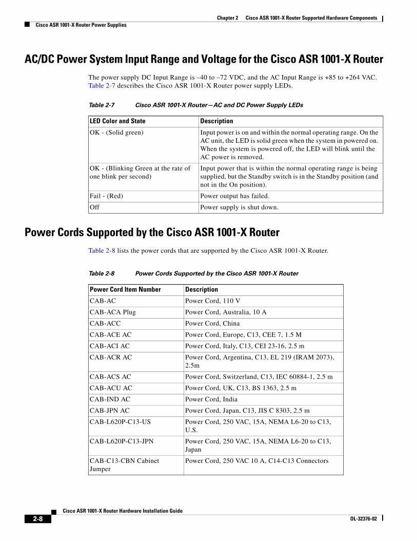
AC/DC Power System Input Range and Voltage for the Cisco ASR 1001-X RouterThe power supply DC Input Range is –40 to –72 VDC, and the AC Input Range is +85 to +264 VAC. Table 2-7 describes the Cisco ASR 1001-X Router power supply LEDs.
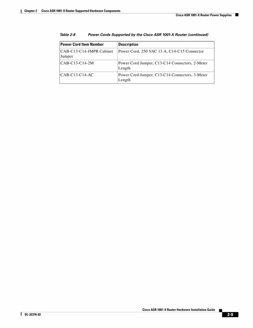
Power Cords Supported by the Cisco ASR 1001-X RouterTable 2-8 lists the power cords that are supported by the Cisco ASR 1001-X Router.
Table 2-7 Cisco ASR 1001-X Router—AC and DC Power Supply LEDs
LED Color and State Description
OK - (Solid green) Input power is on and within the normal operating range. On the AC unit, the LED is solid green when the system in powered on. When the system is powered off, the LED will blink until the AC power is removed.
OK - (Blinking Green at the rate of one blink per second)
Input power that is within the normal operating range is being supplied, but the Standby switch is in the Standby position (and not in the On position).
Fail - (Red) Power output has failed.
Off Power supply is shut down.
Table 2-8 Power Cords Supported by the Cisco ASR 1001-X Router
Power Cord Item Number Description
CAB-AC Power Cord, 110 V
CAB-ACA Plug Power Cord, Australia, 10 A
CAB-ACC Power Cord, China
CAB-ACE AC Power Cord, Europe, C13, CEE 7, 1.5 M
CAB-ACI AC Power Cord, Italy, C13, CEI 23-16, 2.5 m
CAB-ACR AC Power Cord, Argentina, C13, EL 219 (IRAM 2073), 2.5m
CAB-ACS AC Power Cord, Switzerland, C13, IEC 60884-1, 2.5 m
CAB-ACU AC Power Cord, UK, C13, BS 1363, 2.5 m
CAB-IND AC Power Cord, India
CAB-JPN AC Power Cord, Japan, C13, JIS C 8303, 2.5 m
CAB-L620P-C13-US Power Cord, 250 VAC, 15A, NEMA L6-20 to C13, U.S.
CAB-L620P-C13-JPN Power Cord, 250 VAC, 15A, NEMA L6-20 to C13, Japan
CAB-C13-CBN Cabinet Jumper
Power Cord, 250 VAC 10 A, C14-C13 Connectors
2-8Cisco ASR 1001-X Router Hardware Installation Guide
OL-32376-02
Chapter 2 Cisco ASR 1001-X Router Supported Hardware ComponentsCisco ASR 1001-X Router Power Supplies
CAB-C13-C14-JMPR Cabinet Jumper
Power Cord, 250 VAC 13 A, C14-C15 Connector
CAB-C13-C14-2M Power Cord Jumper, C13-C14 Connectors, 2-Meter Length
CAB-C13-C14-AC Power Cord Jumper, C13-C14 Connectors, 3-Meter Length
Table 2-8 Power Cords Supported by the Cisco ASR 1001-X Router (continued)
Power Cord Item Number Description
2-9Cisco ASR 1001-X Router Hardware Installation Guide
OL-32376-02
Chapter 2 Cisco ASR 1001-X Router Supported Hardware ComponentsCisco ASR 1001-X Router Power Supplies
2-10Cisco ASR 1001-X Router Hardware Installation Guide
OL-32376-02
CisOL-32376-02
C H A P T E R 3
Preparing Your Site for InstallationThis chapter contains important safety information you should know before working with the Cisco ASR 1001-X Router, and guides you through the process of preparing your site for router installation.
This chapter contains the following sections:
• Prerequisites and Preparation, page 3-1
• Safety Guidelines, page 3-2
• Compliance Requirements, page 3-3
• Cautions and Regulatory Compliance Statements for NEBS, page 3-4
• Standard Warning Statements, page 3-5
• Site Planning, page 3-8
• Preventing Electrostatic Discharge Damage, page 3-17
• Electrical Safety, page 3-18
• Chassis-Lifting Guidelines, page 3-18
• Tools and Equipment, page 3-19
• Checking the Shipping Container Contents, page 3-19
• Cisco ASR 1001-X Router Installation Checklist, page 3-20
Prerequisites and Preparation Before you perform the procedures in this guide, we recommend that you:
• Read the safety guidelines in the next section and review the electrical safety and ESD-prevention guidelines in this guide.
• Ensure that you have all of the necessary tools and equipment (see the “Tools and Equipment” section on page 3-19).
• Ensure that you have access to the Cisco ASR 1000 Series Aggregation Services Routers Software Configuration Guide (an online document that is available for viewing or download at Cisco.com) during the installation.
• Ensure that the power and cabling requirements are in place at your installation site.
• Ensure that the equipment required to install the router is available.
• Ensure that your installation site meets the environmental conditions to maintain normal operation.
3-1co ASR 1001-X Router Hardware Installation Guide
Chapter 3 Preparing Your Site for InstallationSafety Guidelines
Before installing the Cisco ASR 1001-X Router, you must consider power and cabling requirements that must be in place at your installation site, special equipment for installing the router, and the environmental conditions your installation site must meet to maintain normal operation.
The shipping package for the router is engineered to reduce the chances of product damage associated with routine material handling experienced during shipment:
• Router should always be transported or stored in its shipping package in the upright position.
• Keep the router in the shipping container until you have determined the installation site.
Note Inspect all items for shipping damage. If an item appears damaged, contact a Cisco customer service representative immediately.
Site Planning ChecklistUse the following checklist to perform and account for all the site-planning tasks described in this chapter:
• The site air conditioning system can compensate for the heat dissipation of the Cisco ASR 1001-X Router.
• Electrical service to the site complies with the requirements.
• The electrical circuit servicing the Cisco ASR 1001-X Router complies with the requirements.
• Consideration has been given to console port wiring and limitations of the cabling involved, according to TIA/EIA-232F.
• The Cisco ASR 1001-X Router Ethernet cabling distances are within limitations.
• The equipment rack in which you plan to install the Cisco ASR 1001-X Router chassis complies with requirements. Careful consideration has be given to safety, ease of maintenance, and proper airflow in selecting the location of the rack.
Safety Guidelines Before you begin the installation or replacement procedure, review the safety guidelines in this section to avoid injuring yourself or damaging the equipment.
Note This section contains guidelines, and do not include every potentially hazardous situation. When you install a router, always use common sense and caution.
Safety Warnings Safety warnings appear throughout this publication in procedures that, if performed incorrectly, might harm you. A warning symbol precedes each warning statement.
Before you install, configure, or perform maintenance on the router, review the documentation for the procedure you are about to perform, paying special attention to the safety warnings.
3-2Cisco ASR 1001-X Router Hardware Installation Guide
OL-32376-02
Chapter 3 Preparing Your Site for InstallationCompliance Requirements
Note Do not unpack the system until you are ready to install it. Keep the chassis in the shipping container to prevent accidental damage until you determine an installation site. Use the appropriate unpacking documentation included with the system.
Read the installation instructions in this document before you connect the system to its power source. Failure to read and follow these guidelines could lead to an unsuccessful installation and possibly damage the system and components.
Safety RecommendationsThe following guidelines will help to ensure your own safety and protect your Cisco equipment. This list does not cover all potentially hazardous situations, so be alert.
• Cisco safety policy mandates that all its routers must conform to the requirements of IEC 60950, with appropriate national deviations, as a minimum. In addition, Cisco routers must also meet the requirements of any other normative documents, for example, standards, technical specifications, laws or regulations.
• Review the safety warnings listed in Regulatory Compliance and Safety Information for the Cisco ASR 1000 Series Aggregation Services Routers that accompanies your Cisco ASR 1001-X Router, before installing, configuring, or maintaining the router.
• Never attempt to lift an object that might be too heavy for you to lift by yourself.
• Always turn all power supplies off and unplug all power cables before opening the chassis.
• Always unplug the power cable before installing or removing a chassis.
• Keep the chassis area clear and dust free during and after installation.
• Keep tools and chassis components away from walk areas.
• Do not wear loose clothing, jewelry (including rings and chains), or other items that could get caught in the chassis. Fasten your tie or scarf and sleeves.
• The Cisco ASR 1001-X Router operates safely when it is used in accordance with its marked electrical ratings and product-usage instructions.
Compliance RequirementsThis section includes Safety Compliance and Network Equipment Building Systems (NEBS) standards. The Cisco ASR 1001-X Router is in compliance with national and international standards, as described in Table 3-1.
You must observe the following safety guidelines when working with any equipment that connects to electrical power or telephone wiring. These guidelines help you avoid injuring yourself or damaging the devices.
Note The NEBS information is for reference. The Cisco ASR 1001-X Router is not NEBS certified.
3-3Cisco ASR 1001-X Router Hardware Installation Guide
OL-32376-02
Chapter 3 Preparing Your Site for InstallationCautions and Regulatory Compliance Statements for NEBS
Note The English warnings in this document are followed by a statement number. To see the translations of a warning in other languages, look up its statement number in Regulatory, Compliance, and Safety Information for the Cisco Aggregation Services Router 1000 Series.
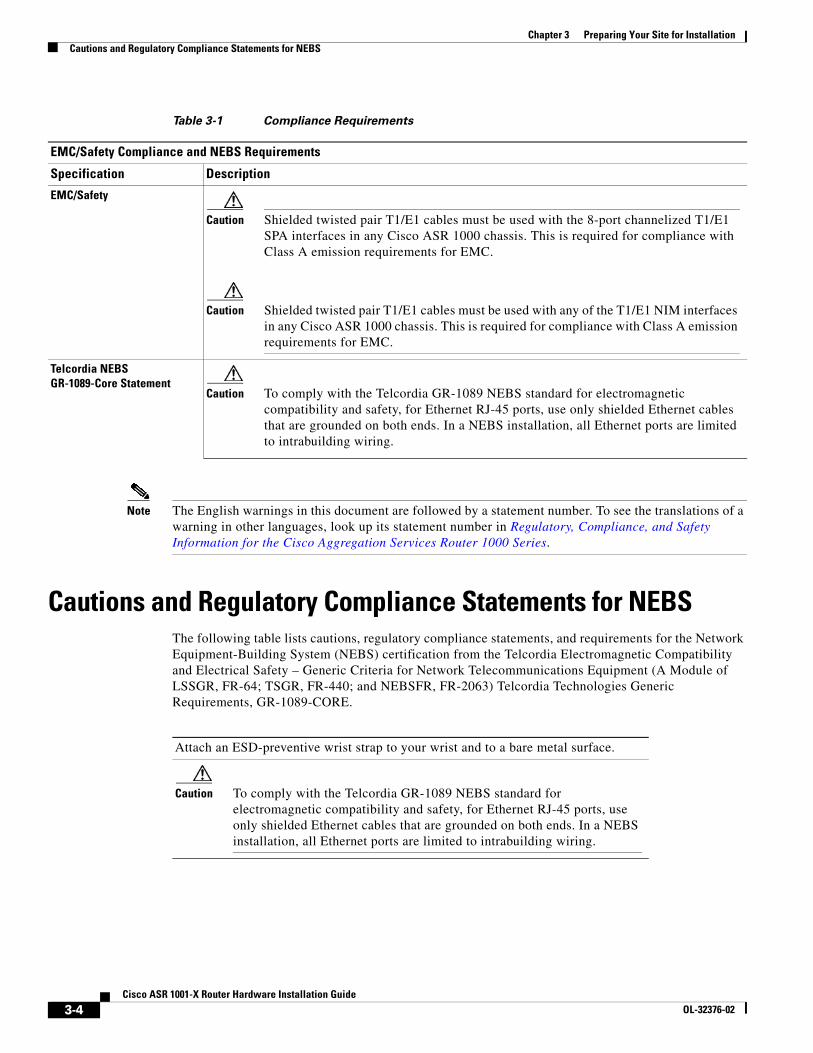
Cautions and Regulatory Compliance Statements for NEBS The following table lists cautions, regulatory compliance statements, and requirements for the Network Equipment-Building System (NEBS) certification from the Telcordia Electromagnetic Compatibility and Electrical Safety – Generic Criteria for Network Telecommunications Equipment (A Module of LSSGR, FR-64; TSGR, FR-440; and NEBSFR, FR-2063) Telcordia Technologies Generic Requirements, GR-1089-CORE.
Table 3-1 Compliance Requirements
EMC/Safety Compliance and NEBS Requirements
Specification Description
EMC/Safety
Caution Shielded twisted pair T1/E1 cables must be used with the 8-port channelized T1/E1 SPA interfaces in any Cisco ASR 1000 chassis. This is required for compliance with Class A emission requirements for EMC.
Caution Shielded twisted pair T1/E1 cables must be used with any of the T1/E1 NIM interfaces in any Cisco ASR 1000 chassis. This is required for compliance with Class A emission requirements for EMC.
Telcordia NEBS GR-1089-Core Statement
Caution To comply with the Telcordia GR-1089 NEBS standard for electromagnetic compatibility and safety, for Ethernet RJ-45 ports, use only shielded Ethernet cables that are grounded on both ends. In a NEBS installation, all Ethernet ports are limited to intrabuilding wiring.
Attach an ESD-preventive wrist strap to your wrist and to a bare metal surface.
Caution To comply with the Telcordia GR-1089 NEBS standard for electromagnetic compatibility and safety, for Ethernet RJ-45 ports, use only shielded Ethernet cables that are grounded on both ends. In a NEBS installation, all Ethernet ports are limited to intrabuilding wiring.
3-4Cisco ASR 1001-X Router Hardware Installation Guide
OL-32376-02

Chapter 3 Preparing Your Site for InstallationStandard Warning Statements
Standard Warning StatementsThis section describes the warning definition and then lists core safety warnings grouped by topic.
Warning This warning symbol means danger. You are in a situation that could cause bodily injury. Before you work on any equipment, be aware of the hazards involved with electrical circuitry and be familiar with standard practices for preventing accidents. Use the statement number provided at the end of each warning to locate its translation in the translated safety warnings that accompanied this device.
Note: SAVE THESE INSTRUCTIONSStatement 1071
General Safety Warnings
Warning Read the installation instructions before you connect the system to its power source. Statement 1004
Caution The intrabuilding ports of the equipment or subassembly are only suitable for connection to intrabuilding or unexposed wiring or cabling. The intrabuilding ports of the equipment or subassembly must not be metallically connected to interfaces that connect to the OSP or its wiring. These interfaces are designed for use only as intrabuilding interfaces (Type 2 or Type 4 ports as described in GR-1089-CORE), and require isolation from the exposed OSP cabling. The addition of primary protectors is not sufficient protection to connect these interfaces metallically to OSP wiring.
Products that have an AC power connection are intended for deployments where an external surge protective device (SPD) is used at the AC power service equipment as defined by the National Electric Code (NEC).
This product is designed for a common bonding network (CBN) installation.
This product can be installed in a network telecommunication facility or location where the NEC applies.
An electrical conducting path shall exist between the product chassis and the metal surface of the enclosure or rack in which it is mounted or to a grounding conductor. Electrical continuity shall be provided by using thread-forming type mounting screws that remove any paint or nonconductive coatings and establish a metal-to-metal contact. Any paint or other nonconductive coatings shall be removed on the surfaces between the mounting hardware and the enclosure or rack. The surfaces shall be cleaned and an antioxidant applied before installation.
The grounding architecture of this product is DC-isolated (DC-I).
DC-powered products have a nominal operating DC voltage of 48 VDC. Minimal steady-state DC operating voltage is 40.5 VDC. Reference American National Standards Institute (ANSI) T1.315, Table 1.
3-5Cisco ASR 1001-X Router Hardware Installation Guide
OL-32376-02
Chapter 3 Preparing Your Site for InstallationStandard Warning Statements
Warning Ultimate disposal of this product should be handled according to all national laws and regulations. Statement 1040
Warning No user-serviceable parts inside Do not open. Statement 1040
Warning Installation of the equipment must comply with local and national electrical codes. Statement 1074
Warning Shielded twisted pair T1/E1 cables must be used with the 8-port channelized T1/E1 SPA interfaces in any Cisco ASR 1000 chassis. This is required for compliance with Class A emission requirements for EMC.
Warning Shielded twisted pair T1/E1 cables must be used with any of the T1/E1 NIM interfaces in any Cisco ASR 1000 chassis. This is required for compliance with Class A emission requirements for EMC.
Warning To comply with Class A emissions requirements- shielded management Ethernet, CON, and AUX cables on the Cisco ASR 1001-X Router must be used.
Warning Power cable and AC adapter - When installing the product, please use the provided or designated connection cables/power cables/AC adapters. Using any other cables or adapters could cause a malfunction or a fire. Electrical Appliance and Material Safety Law prohibits the use of certified cables (that have the ‘UL’ shown on the code) for any other electrical devices than products designated by Cisco. The use of cables that are certified by Electrical Appliance and Material Safety Law (that have ‘PSE’ shown on the code) is not limited to Cisco-designated products. Statement 371
Warning Only trained and qualified personnel should be allowed to install or replace this equipmentStatement 1030
Warning This product relies on the building’s installation for short-circuit (overcurrent) protection. Ensure that the protective device is rated not greater than: AC power supply for the Cisco ASR 1001-X Router: 120 VAC, 30A U.S. maximum. DC power supply for the Cisco ASR 1001-X Router: 30A U.S. maximum. Statement 1005
Warning This product requires short-circuit (overcurrent) protection to be provided as part of the building installation. Install only in accordance with national and local wiring regulations. Statement 1045
3-6Cisco ASR 1001-X Router Hardware Installation Guide
OL-32376-02

Chapter 3 Preparing Your Site for InstallationStandard Warning Statements
Warning This unit may have more than one power supply connection. All connections must be removed to de-energize the unit. Statement 1028
Warning This unit is intended for installation in restricted access areas. A restricted access area can be accessed only through the use of a special tool, lock and key, or other means of security. Statement 1017
Warning The plug-socket combination must be accessible at all times, because it serves as the main disconnecting device. Statement 1019
Warning Hazardous voltage or energy may be present on the DC power terminals. Always replace cover when terminals are not in service. Be sure uninsulated conductors are not accessible when cover is in place. Statement 1075
Warning Use copper conductors only. Statement 1025
Warning This equipment must be grounded. Never defeat the ground conductor or operate the equipment in the absence of a suitably installed ground conductor. Contact the appropriate electrical inspection authority or an electrician if you are uncertain that suitable grounding is available. Statement 1024
Warning Hazardous voltage or energy is present on the backplane when the system is operating. Use caution when servicing. Statement 1034
Warning Class 1 laser product. Statement 1008
Warning Class 1 LED product. Statement 1027
Warning Laser radiation is present when the system is open. Statement 1009
Warning Do not stare into the laser beam. Statement 1010
Warning Class I(CDRH) and Class 1M (IEC) laser products. Statement 1055
3-7Cisco ASR 1001-X Router Hardware Installation Guide
OL-32376-02
Chapter 3 Preparing Your Site for InstallationSite Planning
Warning Invisible laser radiation may be emitted from the end of the unterminated fiber cable or connector. Do not view directly with optical instruments. Viewing the laser output with certain optical instruments (for example, eye loupes, magnifiers, and microscopes) within a distance of 100 mm may pose an eye hazard. Statement 1056
Warning There is the danger of explosion if the battery is replaced incorrectly. Replace the battery only with the same or equivalent type recommended by the manufacturer. Dispose of used batteries according to the manufacturer’s instructions. Statement 1015
Warning Do not touch or bridge the metal contacts on the battery. Unintentional discharge of the batteries can cause serious burns. Statement 341
Warning To prevent personal injury or damage to the chassis, never attempt to lift or tilt the chassis using the handles on modules (such as power supplies, fans, or cards); these types of handles are not designed to support the weight of the unit. Statement 1032
Warning To prevent the system from overheating, do not operate it in an area that exceeds the maximum recommended ambient temperature of: 40 degrees C. Statement 1047
Warning This equipment must be externally grounded using a customer-supplied ground wire before power is applied. Contact the appropriate electrical inspection authority or an electrician if you are uncertain that suitable grounding is available. Statement 366
Warning Blank faceplates and cover panels serve three important functions: they prevent exposure to hazardous voltages and currents inside the chassis; they contain electromagnetic interference (EMI) that might disrupt other equipment; and they direct the flow of cooling air through the chassis. Do not operate the system unless all cards, faceplates, front covers, and rear covers are in place. Statement 1029
Site PlanningThis section contains site-planning information, and will help you plan for the installation of the Cisco ASR 1001-X Router.
General PrecautionsObserve the following general precautions when using and working with your Cisco ASR 1001-X Router:
• Keep your system components away from radiators and heat sources and do not block cooling vents.
3-8Cisco ASR 1001-X Router Hardware Installation Guide
OL-32376-02
Chapter 3 Preparing Your Site for InstallationSite Planning
• Do not spill food or liquids on your system components and never operate the product in a wet environment.
• Do not push any objects into the openings of your system components. Doing so can cause fire or electric shock by shorting out interior components.
• Position system cables and power supply cable carefully. Route system cables and power supply cable and plug such that they cannot be stepped on or tripped over. Be sure that nothing else rests on your system component cables or power cable.
• Do not modify power cables or plugs. Consult a licensed electrician or your power company for site modifications. Always follow your local and national wiring rules.
• If you turn off your system, wait at least 30 seconds before turning it on again to avoid system component damage.
Site Selection GuidelinesThe Cisco ASR 1001-X Router requires specific environmental operating conditions. Temperature, humidity, altitude, and vibration can affect the performance and reliability of the router. The following sections provide specific information to help you plan for a proper operating environment.
The Cisco ASR 1001-X Router is designed to meet the industry EMC, safety, and environmental standards described in the Regulatory, Safety, and Compliance Information for Cisco ASR 1000 Series Aggregation Services Routers document.
Site Environmental Requirements
Environmental monitoring protects the system and components from damage caused by excessive voltage and temperature conditions. To ensure normal operation and avoid unnecessary maintenance, plan and prepare your site configuration before installation. After installation, make sure the site maintains the environmental characteristics, as shown in Table 3-2.
Table 3-2 Cisco ASR 1001-X Router Environmental Tolerance
Environmental Characteristic Minimum Maximum
Operating temperature (nominal) 0° C 40° C
(40° C up to 10,000 feet)
Operating temperature (short term) 0° C 50° C
Storage temperature –20° C +70° C
Operative humidity (nominal) (relative humidity) 10% 90%
Operative humidity (short term) 5% 90%
Storage humidity (relative humidity) 5% 95%
Altitude, operating: over allowable temperature range (0 to 50 degrees C)
–500 feet 10,000 feet
Altitude, nonoperating: over allowable temperature range
–1000 feet 50,000 feet
3-9Cisco ASR 1001-X Router Hardware Installation Guide
OL-32376-02
Chapter 3 Preparing Your Site for InstallationSite Planning
Physical Characteristics
Be familiar with the physical characteristics of the Cisco ASR 1001-X Router to assist you in placing the system at a proper location.
Note For information regarding rack widths supported for the Cisco ASR 1001-X Router, see the following sections:
• 19 in.—“General Rack-Selection Guidelines” section on page 3-15
• 23 in.—“Guidelines for 23-in. (Telco) Racks” section on page 3-16
Table 3-3 shows the weight and dimensions of the Cisco ASR 1001-X Routers.
The following list describes additional Cisco ASR 1001-X Router characteristics:
• Chassis height meets EIA-310 rack spacing 1RU (1.71 in. or 43.43 mm), universal rack mount
• Chassis width meets EIA-310 19 in. (17.3 in. or 439.42 mm) wide with rack brackets
• Cable-management brackets allow a bend radius of 1.5 in. (38.1 mm) for cables
• Ships with forward rack-mount brackets installed and an extra set included in the accessory kit
Thermal shock nonoperating with change over time of 3 minutes
–25° C +70° C
Thermal Shock - Operating at 2.5 degree C per minute
0° C +50° C
Table 3-2 Cisco ASR 1001-X Router Environmental Tolerance (continued)
Environmental Characteristic Minimum Maximum
Table 3-3 Physical Characteristics of Cisco ASR 1001-X Router
Characteristic Cisco ASR 1001-X
Height 1.71 in. (43.43 mm) —1RU; rack-mount per EIA RS-310
Width 17.3 in. (439.42 mm)
Depth 22.50 in. (571.5 mm) Depth includes cable-management brackets; card and power-supply handles for mounting in a 600 mm enclosed cabinet.
Weight 25 lb (11.35 kg) fully loaded
3-10Cisco ASR 1001-X Router Hardware Installation Guide
OL-32376-02
Chapter 3 Preparing Your Site for InstallationSite Planning
Site Power GuidelinesThe Cisco ASR 1001-X Router has specific power and electrical wiring requirements. Adhering to these requirements ensures reliable operation of the system. Follow these precautions and recommendations when planning your site for the Cisco ASR 1001-X Router:
• The redundant power option provides a second, identical power supply to ensure that power to the chassis continues uninterrupted if one power supply fails or input power on one line fails.
• In systems configured with the redundant power option, connect each of the two power supplies to a separate input power source. If you fail to do this, your system might be susceptible to total power failure due to a fault in the external wiring or a tripped circuit breaker.
• To prevent a loss of input power, be sure the total maximum load on each circuit supplying the power supplies is within the current ratings of the wiring and breakers.
• Check the power at your site before installation, and periodically after installation, to ensure that you are receiving clean power. Install a power conditioner if necessary.
• Provide proper grounding to avoid personal injury and damage to the equipment due to lightning striking power lines or due to power surges. The chassis ground must be attached to a central office or other interior ground system.
Caution This product requires short-circuit (overcurrent) protection to be provided as part of the building installation. Install only in accordance with national and local wiring regulations.
Note The Cisco ASR 1001-X Router installation must comply with all applicable codes and is approved for use with copper conductors only. The ground bond fastening hardware should be of compatible material and preclude loosening, deterioration, and electrochemical corrosion of hardware and joined material. Attachment of the chassis ground to a central office or other interior ground system must be made with an AWG #6 gauge wire, copper ground conductor at a minimum.
Electrical Circuit Requirements
Each Cisco ASR 1001-X Router requires a dedicated electrical circuit. If you equip it with dual-power feeds, you must provide a separate circuit for each power supply to avoid compromising the power redundancy feature.
The Cisco ASR 1001-X Router can be powered by a DC or AC source. Ensure that equipment grounding is present and observe power-strip ratings. Make sure that the total ampere rating of all the products plugged into the power strip does not exceed 80 percent of the rating.
Note The Cisco ASR 1001-X Router can support two AC or two DC power supplies. Do not install mixed AC and DC power supply units in the same chassis.
3-11Cisco ASR 1001-X Router Hardware Installation Guide
OL-32376-02
Chapter 3 Preparing Your Site for InstallationSite Planning
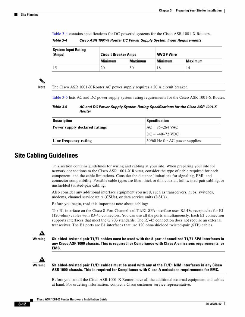
Table 3-4 contains specifications for DC-powered systems for the Cisco ASR 1001-X Routers.
Note The Cisco ASR 1001-X Router AC power supply requires a 20 A circuit breaker.
Table 3-5 lists AC and DC power supply system rating requirements for the Cisco ASR 1001-X Router.
Site Cabling GuidelinesThis section contains guidelines for wiring and cabling at your site. When preparing your site for network connections to the Cisco ASR 1001-X Router, consider the type of cable required for each component, and the cable limitations. Consider the distance limitations for signaling, EMI, and connector compatibility. Possible cable types are fiber, thick or thin coaxial, foil twisted-pair cabling, or unshielded twisted-pair cabling.
Also consider any additional interface equipment you need, such as transceivers, hubs, switches, modems, channel service units (CSUs), or data service units (DSUs).
Before you begin, read this important note about cabling:
The E1 interface on the Cisco 8-Port Channelized T1/E1 SPA interface uses RJ-48c receptacles for E1 (120-ohm) cables with RJ-45 connectors. You can use all the ports simultaneously. Each E1 connection supports interfaces that meet the G.703 standards. The RJ-45 connection does not require an external transceiver. The E1 ports are E1 interfaces that use 120 ohm-shielded twisted-pair (STP) cables.
Warning Shielded-twisted pair T1/E1 cables must be used with the 8-port channelized T1/E1 SPA interfaces in any Cisco ASR 1000 chassis. This is required for Compliance with Class A emissions requirements for EMC.
Warning Shielded-twisted pair T1/E1 cables must be used with any of the T1/E1 NIM interfaces in any Cisco ASR 1000 chassis. This is required for Compliance with Class A emissions requirements for EMC.
Before you install the Cisco ASR 1001-X Router, have all the additional external equipment and cables at hand. For ordering information, contact a Cisco customer service representative.
Table 3-4 Cisco ASR 1001-X Router DC Power Supply System Input Requirements
System Input Rating (Amps) Circuit Breaker Amps AWG # Wire
Minimum Maximum Minimum Maximum
15 20 30 18 14
Table 3-5 AC and DC Power Supply System Rating Specifications for the Cisco ASR 1001-X
Router
Description Specification
Power supply declared ratings AC = 85–264 VAC
DC = –40–72 VDC
Line frequency rating 50/60 Hz for AC power supplies
3-12Cisco ASR 1001-X Router Hardware Installation Guide
OL-32376-02
Chapter 3 Preparing Your Site for InstallationSite Planning
The extent of your network and the distances between network interface connections depend in part on the following factors:
• Signal type
• Signal speed
• Transmission medium
The distance and rate limits referenced in the following sections are the IEEE-recommended maximum speeds and distances for signaling purposes. Use this information as guidelines when planning your network connections prior to installing the Cisco ASR 1001-X Router.
If wires exceed recommended distances, or if wires pass between buildings, give special consideration to the effect of a lightning strike in your vicinity. The electromagnetic pulse caused by lightning or other high-energy phenomena can easily couple enough energy into unshielded conductors to destroy electronic devices. If you have had problems of this sort in the past, you may want to consult experts in electrical surge suppression and shielding.
Console Port Connections
The Cisco ASR 1001-X Router provides console and auxiliary ports to connect a terminal or computer for local console access.
Both ports have RJ-45 connectors, support RS-232 asynchronous data, and have distance recommendations specified in the IEEE RS-232 standard.
USB Serial Console
The USB serial console port connects directly to the USB connector of a PC using a USB Type A to 5-pin mini USB Type-B cable. The USB Console supports full speed (12Mbps) operation. The console port does not support hardware flow control.
Note • Always use shielded USB cables with a properly terminated shield. The USB serial console interface cable must not exceed 3 meters in length.
• Only one console port can be active at a time. When a cable is plugged into the USB console port, the RJ-45 port becomes inactive. Conversely, when the USB cable is removed from the USB port, the RJ-45 port becomes active.
• 4-pin mini USB Type-B connectors are easily confused with 5-pin mini USB Type-B connectors. Only 5-pin mini USB Type-B is supported.
Interference Considerations
When wires are run for a significant distance, there is a risk that stray signals will be induced on the wires as interference. If interference signals are strong, they can cause data errors or damage to the equipment.
The following sections describe sources of interference and how to minimize its effects on the Cisco ASR 1001-X Router.
3-13Cisco ASR 1001-X Router Hardware Installation Guide
OL-32376-02
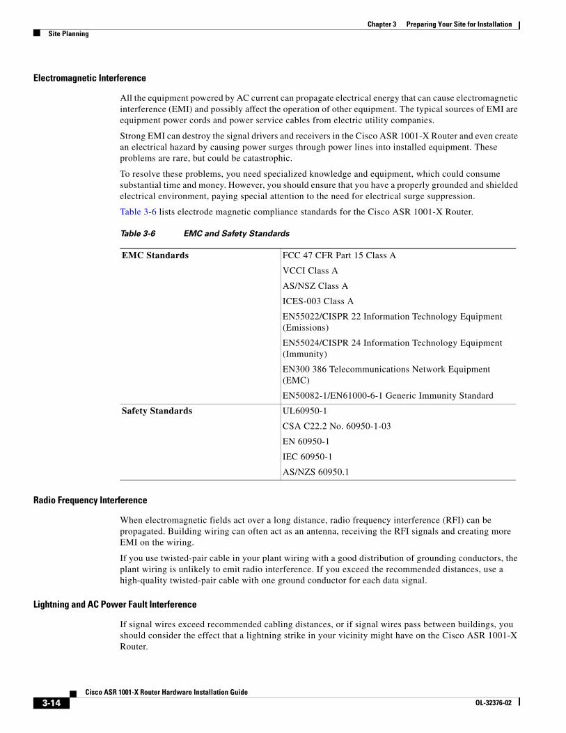
Chapter 3 Preparing Your Site for InstallationSite Planning
Electromagnetic Interference
All the equipment powered by AC current can propagate electrical energy that can cause electromagnetic interference (EMI) and possibly affect the operation of other equipment. The typical sources of EMI are equipment power cords and power service cables from electric utility companies.
Strong EMI can destroy the signal drivers and receivers in the Cisco ASR 1001-X Router and even create an electrical hazard by causing power surges through power lines into installed equipment. These problems are rare, but could be catastrophic.
To resolve these problems, you need specialized knowledge and equipment, which could consume substantial time and money. However, you should ensure that you have a properly grounded and shielded electrical environment, paying special attention to the need for electrical surge suppression.
Table 3-6 lists electrode magnetic compliance standards for the Cisco ASR 1001-X Router.
Radio Frequency Interference
When electromagnetic fields act over a long distance, radio frequency interference (RFI) can be propagated. Building wiring can often act as an antenna, receiving the RFI signals and creating more EMI on the wiring.
If you use twisted-pair cable in your plant wiring with a good distribution of grounding conductors, the plant wiring is unlikely to emit radio interference. If you exceed the recommended distances, use a high-quality twisted-pair cable with one ground conductor for each data signal.
Lightning and AC Power Fault Interference
If signal wires exceed recommended cabling distances, or if signal wires pass between buildings, you should consider the effect that a lightning strike in your vicinity might have on the Cisco ASR 1001-X Router.
Table 3-6 EMC and Safety Standards
EMC Standards FCC 47 CFR Part 15 Class A
VCCI Class A
AS/NSZ Class A
ICES-003 Class A
EN55022/CISPR 22 Information Technology Equipment (Emissions)
EN55024/CISPR 24 Information Technology Equipment (Immunity)
EN300 386 Telecommunications Network Equipment (EMC)
EN50082-1/EN61000-6-1 Generic Immunity Standard
Safety Standards UL60950-1
CSA C22.2 No. 60950-1-03
EN 60950-1
IEC 60950-1
AS/NZS 60950.1
3-14Cisco ASR 1001-X Router Hardware Installation Guide
OL-32376-02
Chapter 3 Preparing Your Site for InstallationSite Planning
The electromagnetic pulse (EMP) generated by lightning or other high-energy phenomena can couple enough energy into unshielded conductors to damage or destroy electronic equipment. If you have previously experienced such problems, you should consult with RFI/EMI experts to ensure that you have adequate electrical surge suppression and shielding of signal cables in your Cisco ASR 1001-X Router operating environment.
Rack-Mounting GuidelinesThis section describes guidelines on rack-mounting.
Precautions for Rack-Mounting
The following rack-mounting guidelines are provided to ensure your safety:
• Do not move large racks by yourself. Due to the height and weight of a rack, a minimum of two people are required to accomplish this task.
• Ensure that the rack is level and stable before extending a component from the rack.
• Ensure that proper airflow is provided to the components in the rack.
• Do not step or stand on any component or system when servicing other systems or components in a rack.
• When mounting the Cisco ASR 1001-X Router in a partially filled rack, load the rack from the bottom to the top with the heaviest component at the bottom of the rack.
• If the rack is provided with stabilizing devices, install the stabilizers before mounting or servicing the unit in the rack.
General Rack-Selection Guidelines
The Cisco ASR 1001-X Router can be mounted in most two-post or four-post, 19-in. equipment racks that comply with the Electronics Industries Association (EIA) standard for equipment racks (EIA-310-D 19-in.). The rack must have at least two posts with mounting flanges to mount the chassis.
Caution When mounting a chassis in any type of rack equipment, ensure that the inlet air to the chassis does not exceed 131°F (55°C).
The distance between the center lines of the mounting holes on the two mounting posts must be 18.31 in. ± 0.06 in. (46.50 cm ± 0.15 cm). The rack-mounting hardware included with the chassis is suitable for most 19-in. (48.3-cm) equipment racks.
Consider installing the Cisco ASR 1001-X Router in a rack with the following features:
• NEBS-compliant, 19-in. (48.3-cm) wide rack.
• EIA or ETSI hole patterns in the mounting rails. Required mounting hardware is shipped with the Cisco ASR 1001-X Router. If the rack that you plan to install the system in has metric-threaded rails, you must provide your own metric-mounting hardware.
• Perforated top and open bottom for ventilation to prevent overheating.
• Leveling feet for stability.
3-15Cisco ASR 1001-X Router Hardware Installation Guide
OL-32376-02
Chapter 3 Preparing Your Site for InstallationSite Planning
Note The Cisco ASR 1001-X Router should not be installed in an enclosed rack because the chassis requires an unobstructed flow of cooling air to maintain acceptable operating temperatures for its internal components. Installing the router in any type of enclosed rack—even with the front and back doors removed—could disrupt the air flow, trap heat next to the chassis, and cause an overtemperature condition inside the router. If you use an enclosed rack, make certain that there are air vents on all sides of the rack and there is proper ventilation.
Guidelines for 23-in. (Telco) Racks
If needed, you can also install the Cisco ASR 1001-X Router in 23-in. (Telco) racks. For information on the adapters needed for 23 in. racks, contact the Newton Instrument Company:
http://www.enewton.com
111 East A Street, Butner NC, USA, 27509
919 575-6426
Equipment Rack Guidelines
The placement of racks can affect personnel safety, system maintenance, and the system’s ability to operate within the environmental characteristics described in Table 3-2. Choose a proper location for the Cisco ASR 1001-X Router by following the guidelines below.
Locating for Safety
If the Cisco ASR 1001-X Router is the heaviest or the only piece of equipment in the rack, consider installing it at or near the bottom to ensure that the rack’s center of gravity is as low as possible.
For additional information about the proper placement of electronic equipment, see the document GR-63-CORE, Network Equipment Building System (NEBS) Requirements: Physical Protection.
Locating for Easy Maintenance
Keep at least 3 feet of clear space in front of and behind the rack. This space ensures that you can remove the Cisco ASR 1001-X Router components and perform routine maintenance and upgrades easily.
Avoid installing the Cisco ASR 1001-X Router in a congested rack and consider how the routing of cables from other pieces of equipment in the same rack might affect access to the routers cards.
The front and top of the chassis must remain unobstructed to ensure adequate airflow and prevent overheating inside the chassis.
Allow the following clearances for normal system maintenance:
• At the top of the chassis—At least 3 in. (7.6 cm)
• In front of the chassis—3 to 4 ft (91.44 cm to 121.92 cm)
To avoid problems during installation and ongoing operation, follow these general precautions when you plan the equipment locations and connections:
• Use the show environment all and the show facility-alarm status command regularly to check the internal system status. The environmental monitor continually checks the interior chassis environment; it provides warnings for high temperature and creates reports on any occurrences. If warning messages are displayed, take immediate action to identify the cause and correct the problem. For more information on these commands, see the “Environmental Monitoring and
3-16Cisco ASR 1001-X Router Hardware Installation Guide
OL-32376-02
Chapter 3 Preparing Your Site for InstallationPreventing Electrostatic Discharge Damage
Reporting Functions” section on page 5-15.
• Keep the Cisco ASR 1001-X Router off the floor and out of the areas that collect dust.
• Follow ESD-prevention procedures to avoid damage to equipment. Damage from static discharge can cause immediate or intermittent equipment failure.
Locating for Proper Airflow
Ensure that the location of the Cisco ASR 1001-X Router has enough airflow to keep the system operating within the environmental characteristics, and the air temperature is sufficient to compensate for the heat dissipated by the system.
Avoid locating the Cisco ASR 1001-X Router in a location in which the chassis air intake vents could draw in the exhaust air from adjacent equipment. Consider how the air flows through the router. The airflow direction is front to back with ambient air drawn in from the venting located on the chassis’ front sides.
Preventing Electrostatic Discharge DamageElectrostatic discharge (ESD) damage occurs when electronic cards or components are improperly handled resulting in complete or intermittent failures. Static electricity can harm delicate components inside your system. To prevent static damage, discharge static electricity from your body before you touch any of your system components, such as a microprocessor. As you continue to work on your system, periodically touch an unpainted metal surface on the computer chassis.
The following are guidelines for preventing ESD damage:
• Always use an ESD-preventive wrist or ankle strap and ensure that it makes good skin contact. Before removing a card from the chassis, connect the equipment end of the strap to the ESD plug at the bottom of the chassis below the power entry modules.
• Handle line cards by faceplates and carrier edges only; avoid touching the card components or connector pins.
• When removing a card, place the removed module component-side-up on an antistatic surface or in a static-shielding bag. If the module id to be returned to the factory, immediately place it in a static-shielding bag.
• Avoid contact between the modules and clothing. The wrist strap protects the card from ESD voltages only on the body; ESD voltages on clothing can still cause damage.
• When transporting a sensitive component, place it in an antistatic container or packaging.
• Handle all sensitive components in a static-safe area. If possible, use antistatic floor pads and workbench pads.
Caution For safety, periodically check the resistance value of the antistatic strap. The measurement should be between 1 and 10 ohms.
Caution Always tighten the captive installation screws on all the system components when you are installing them. These screws prevent accidental removal of the module, provide proper grounding for the system, and help ensure that the bus connectors are properly seated in the backplane.
3-17Cisco ASR 1001-X Router Hardware Installation Guide
OL-32376-02
Chapter 3 Preparing Your Site for InstallationElectrical Safety
Electrical SafetyAll the system components are hot-swappable. They are designed to be removed and replaced while the system is operating, without presenting an electrical hazard or damage to the system.
Follow these basic guidelines when you are working with any electrical equipment:
• Before beginning any procedures requiring access to the chassis interior, locate the emergency power-off switch for the room in which you are working.
• Disconnect all power and external cables before installing or removing a chassis.
• Do not work alone when potentially hazardous conditions exist.
• Never assume that power has been disconnected from a circuit; always check.
• Do not perform any action that creates a potential hazard to people or makes the equipment unsafe. Never install equipment that appears damaged.
• Carefully examine your work area for possible hazards such as moist floors, ungrounded power extension cables, and missing safety grounds.
In addition, use the following guidelines when working with any equipment that is disconnected from a power source, but is still connected to telephone wiring or other network cabling:
• Never install telephone wiring during a lightning storm.
• Never install telephone jacks in wet locations unless the jack is specifically designed for wet locations.
• Never touch uninsulated telephone wires or terminals unless the telephone line has been disconnected at the network interface.
• Use caution when installing or modifying telephone lines.
Warning Do not work on the system or connect or disconnect cables during periods of lightning activity. Statement 1006
Chassis-Lifting GuidelinesThe chassis is not intended to be moved frequently. Before you install the system, ensure that your site is properly prepared so that you can avoid having to move the chassis later to accommodate power sources and network connections.
Each time you lift the chassis or any heavy object, follow these guidelines:
• Ensure that your footing is solid, and balance the weight of the chassis between your feet.
• Lift the chassis slowly; never move suddenly or twist your body as you lift.
• Keep your back straight and lift with your legs, not your back. If you must bend down to lift the chassis, bend at the knees, not at the waist, to reduce the strain on your back muscles.
• Do not remove installed components from the chassis.
• Always disconnect all external cables before lifting or moving the chassis.
3-18Cisco ASR 1001-X Router Hardware Installation Guide
OL-32376-02
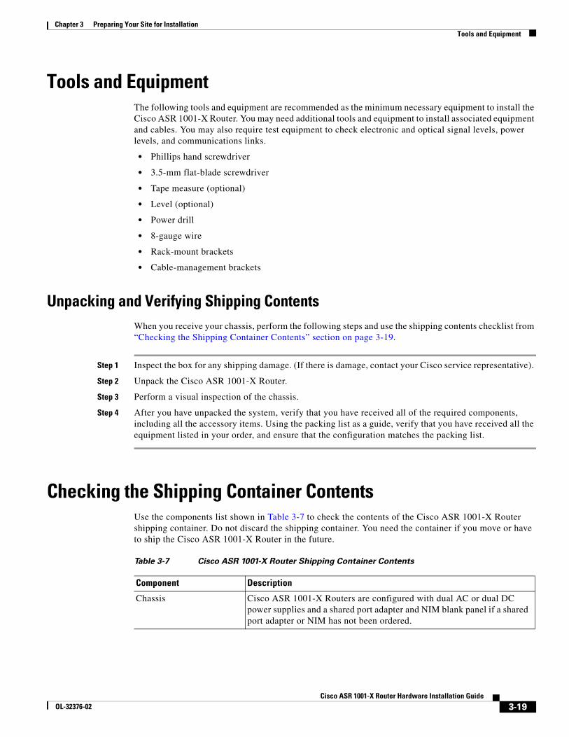
Chapter 3 Preparing Your Site for InstallationTools and Equipment
Tools and EquipmentThe following tools and equipment are recommended as the minimum necessary equipment to install the Cisco ASR 1001-X Router. You may need additional tools and equipment to install associated equipment and cables. You may also require test equipment to check electronic and optical signal levels, power levels, and communications links.
• Phillips hand screwdriver
• 3.5-mm flat-blade screwdriver
• Tape measure (optional)
• Level (optional)
• Power drill
• 8-gauge wire
• Rack-mount brackets
• Cable-management brackets
Unpacking and Verifying Shipping ContentsWhen you receive your chassis, perform the following steps and use the shipping contents checklist from “Checking the Shipping Container Contents” section on page 3-19.
Step 1 Inspect the box for any shipping damage. (If there is damage, contact your Cisco service representative).
Step 2 Unpack the Cisco ASR 1001-X Router.
Step 3 Perform a visual inspection of the chassis.
Step 4 After you have unpacked the system, verify that you have received all of the required components, including all the accessory items. Using the packing list as a guide, verify that you have received all the equipment listed in your order, and ensure that the configuration matches the packing list.
Checking the Shipping Container ContentsUse the components list shown in Table 3-7 to check the contents of the Cisco ASR 1001-X Router shipping container. Do not discard the shipping container. You need the container if you move or have to ship the Cisco ASR 1001-X Router in the future.
Table 3-7 Cisco ASR 1001-X Router Shipping Container Contents
Component Description
Chassis Cisco ASR 1001-X Routers are configured with dual AC or dual DC power supplies and a shared port adapter and NIM blank panel if a shared port adapter or NIM has not been ordered.
3-19Cisco ASR 1001-X Router Hardware Installation Guide
OL-32376-02
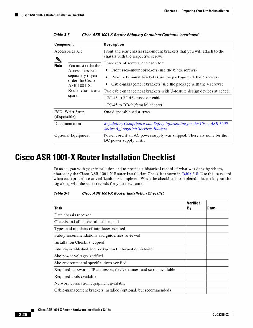
Chapter 3 Preparing Your Site for InstallationCisco ASR 1001-X Router Installation Checklist
Cisco ASR 1001-X Router Installation ChecklistTo assist you with your installation and to provide a historical record of what was done by whom, photocopy the Cisco ASR 1001-X Router Installation Checklist shown in Table 3-8. Use this to record when each procedure or verification is completed. When the checklist is completed, place it in your site log along with the other records for your new router.
Accessories Kit
Note You must order the Accessories Kit separately if you order the Cisco ASR 1001-X Router chassis as a spare.
Front and rear chassis rack-mount brackets that you will attach to the chassis with the respective screws
Three sets of screws, one each for:
• Front rack-mount brackets (use the black screws)
• Rear rack-mount brackets (use the package with the 5 screws)
• Cable-management brackets (use the package with the 4 screws)
Two cable-management brackets with U-feature design devices attached.
1 RJ-45 to RJ-45 crossover cable
1 RJ-45 to DB-9 (female) adapter
ESD, Wrist Strap (disposable)
One disposable wrist strap
Documentation Regulatory Compliance and Safety Information for the Cisco ASR 1000 Series Aggregation Services Routers
Optional Equipment Power cord if an AC power supply was shipped. There are none for the DC power supply units.
Table 3-7 Cisco ASR 1001-X Router Shipping Container Contents (continued)
Component Description
Table 3-8 Cisco ASR 1001-X Router Installation Checklist
TaskVerified By Date
Date chassis received
Chassis and all accessories unpacked
Types and numbers of interfaces verified
Safety recommendations and guidelines reviewed
Installation Checklist copied
Site log established and background information entered
Site power voltages verified
Site environmental specifications verified
Required passwords, IP addresses, device names, and so on, available
Required tools available
Network connection equipment available
Cable-management brackets installed (optional, but recommended)
3-20Cisco ASR 1001-X Router Hardware Installation Guide
OL-32376-02
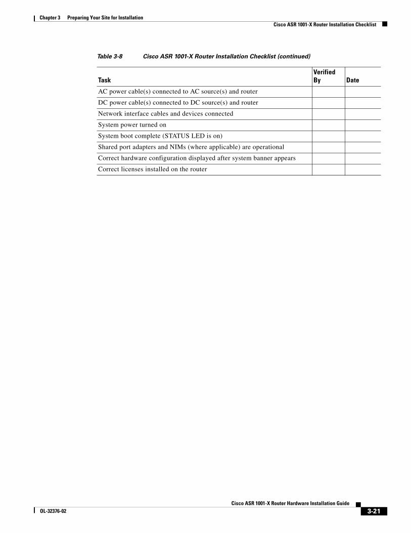
Chapter 3 Preparing Your Site for InstallationCisco ASR 1001-X Router Installation Checklist
AC power cable(s) connected to AC source(s) and router
DC power cable(s) connected to DC source(s) and router
Network interface cables and devices connected
System power turned on
System boot complete (STATUS LED is on)
Shared port adapters and NIMs (where applicable) are operational
Correct hardware configuration displayed after system banner appears
Correct licenses installed on the router
Table 3-8 Cisco ASR 1001-X Router Installation Checklist (continued)
TaskVerified By Date
3-21Cisco ASR 1001-X Router Hardware Installation Guide
OL-32376-02

Chapter 3 Preparing Your Site for InstallationCisco ASR 1001-X Router Installation Checklist
3-22Cisco ASR 1001-X Router Hardware Installation Guide
OL-32376-02
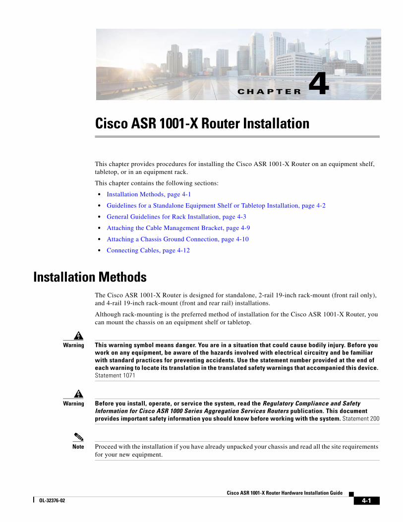
CisOL-32376-02
C H A P T E R 4
Cisco ASR 1001-X Router InstallationThis chapter provides procedures for installing the Cisco ASR 1001-X Router on an equipment shelf, tabletop, or in an equipment rack.
This chapter contains the following sections:
• Installation Methods, page 4-1
• Guidelines for a Standalone Equipment Shelf or Tabletop Installation, page 4-2
• General Guidelines for Rack Installation, page 4-3
• Attaching the Cable Management Bracket, page 4-9
• Attaching a Chassis Ground Connection, page 4-10
• Connecting Cables, page 4-12
Installation MethodsThe Cisco ASR 1001-X Router is designed for standalone, 2-rail 19-inch rack-mount (front rail only), and 4-rail 19-inch rack-mount (front and rear rail) installations.
Although rack-mounting is the preferred method of installation for the Cisco ASR 1001-X Router, you can mount the chassis on an equipment shelf or tabletop.
Warning This warning symbol means danger. You are in a situation that could cause bodily injury. Before you work on any equipment, be aware of the hazards involved with electrical circuitry and be familiar with standard practices for preventing accidents. Use the statement number provided at the end of each warning to locate its translation in the translated safety warnings that accompanied this device. Statement 1071
Warning Before you install, operate, or service the system, read the Regulatory Compliance and Safety Information for Cisco ASR 1000 Series Aggregation Services Routers publication. This document provides important safety information you should know before working with the system. Statement 200
Note Proceed with the installation if you have already unpacked your chassis and read all the site requirements for your new equipment.
4-1co ASR 1001-X Router Hardware Installation Guide
Chapter 4 Cisco ASR 1001-X Router InstallationGuidelines for a Standalone Equipment Shelf or Tabletop Installation
Guidelines for a Standalone Equipment Shelf or Tabletop Installation
The chassis should already be in the area where you want to install it. If you have not determined where to install your chassis, see the “Preparing Your Site for Installation” section on page 3-1 for information about site considerations.
When installing the Cisco ASR 1001-X Router on a sturdy equipment shelf or tabletop, ensure that the surface is clean and that you have considered the following:
• The Cisco ASR 1001-X Router requires at least 3 inches (7.62 cm) of clearance at the inlet and exhaust vents (the front and rear sides of the chassis).
• The Cisco ASR 1001-X Router should be installed off the floor. Dust that accumulates on the floor is drawn into the interior of the router by the cooling fans. Excessive dust inside the router can cause overtemperature conditions and component failures.
• There must be approximately 19 inches (48.3 cm) of clearance at the front and rear of the chassis to install and replace FRUs, or to access network cables and equipment.
• The Cisco ASR 1001-X Router needs adequate ventilation. Do not install it in an enclosed cabinet where ventilation is inadequate.
• Keep the cable-management bracket ready if you plan to install it on the front of the chassis.
• Ensure that an adequate chassis ground (earth) connection exists for your router chassis (see the “Attaching a Chassis Ground Connection” section on page 4-10).
Steps for Installing the Cisco ASR 1001-X Router on a Standalone Equipment Shelf or Tabletop Installation
To mount your Cisco ASR 1001-X Router on an equipment shelf or tabletop, follow these steps.
Step 1 Remove any debris and dust from the tabletop or platform, as well as the surrounding area.
Step 2 Lift the chassis into position on the equipment shelf or tabletop.
Note Step 3 through Step 9 are optional if you are installing the Cisco ASR 1001-X Router on a rack shelf. The chassis rack-mount brackets must be installed prior to installing the cable-management brackets. See the “Attaching the Chassis Rack-Mount Brackets” section on page 4-5 and the “Attaching the Cable Management Bracket” section on page 4-9.
Step 3 Attach the front rack-mount brackets. Locate the threaded holes in the front sides of the chassis (first holes beyond the vent holes) and use the package of black screws that shipped with the chassis.
Step 4 Align the front rack-mount bracket to one side of the chassis.
Step 5 Insert and tighten the screws on one side.
Step 6 Repeat Step 2 through Step 3 on the other side of the chassis. Use all the screws to secure the rack-mount brackets to the chassis.
4-2Cisco ASR 1001-X Router Hardware Installation Guide
OL-32376-02
Chapter 4 Cisco ASR 1001-X Router InstallationGeneral Guidelines for Rack Installation
Note Ensure that the cable-management U feature device has the open end pointing outwards when you attach it to the chassis.
Step 7 Gather the two cable-management brackets and screws shipped with your chassis. See the “Attaching the Cable Management Bracket” section on page 4-9.
Step 8 Screw a cable-management bracket to each side of the rack-mount brackets that are attached to the chassis. Use two screws for each cable-management bracket. Use a screw from the package of four screws.
Step 9 Check that all the screws are securely tightened.
Step 10 Go to the “Attaching a Chassis Ground Connection” section on page 4-10 for instructions about continuing the installation.
General Guidelines for Rack InstallationWhen planning your rack installation, consider the following guidelines:
• The Cisco ASR 1001-X Router requires a minimum of 3.5 inches or 8.9 cm rack units of vertical rack space. Measure the proposed rack location before mounting the chassis in the rack.
• Before using a particular rack, check for obstructions (such as a power strip) that could impair rack-mount installation. If a power strip does impair a rack-mount installation, remove the power strip before installing the chassis, and then replace it after the chassis is installed.
• Allow sufficient clearance around the rack for maintenance. If the rack is mobile, you can push it back near a wall or cabinet for normal operation and pull it out for maintenance (installing or moving cards, connecting cables, or replacing or upgrading components). Otherwise, allow 19 inches (48.3 cm) of clearance to remove field-replaceable units.
• Maintain a minimum clearance of 3 inches on the front and back sides of the chassis for the cooling air inlet and exhaust ports, respectively. Avoid placing the chassis in an overly congested rack or directly next to another equipment rack; the heated exhaust air from other equipment can enter the inlet air vents and cause an overtemperature condition inside the router.
Caution To prevent chassis overheating, never install a Cisco ASR 1001-X Router in an enclosed space that is not properly ventilated or air conditioned.
• Always install heavier equipment in the lower half of a rack to maintain a low center of gravity to prevent the rack from falling over.
• Install and use the cable-management brackets included with the Cisco ASR 1001-X Router to keep cables organized and out of the way of the cards and processors. Ensure that cables from other equipment already installed in the rack do not impair access to the cards or require you to disconnect cables unnecessarily to perform equipment maintenance or upgrades.
• Provide an adequate chassis ground (earth) connection for your router chassis.
In addition to the preceding guidelines, review the precautions for avoiding excessive temperature conditions in the “Physical Characteristics” section on page 3-10 and the “Site Environmental Requirements” section on page 3-9.
4-3Cisco ASR 1001-X Router Hardware Installation Guide
OL-32376-02
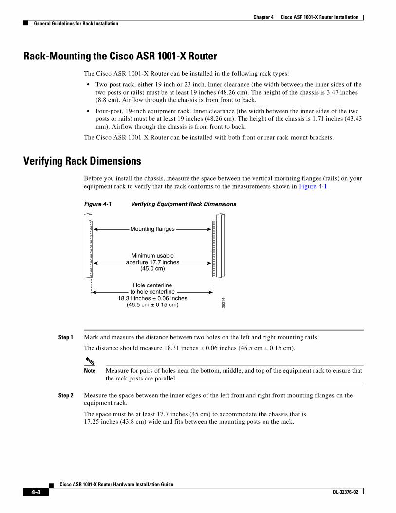
Chapter 4 Cisco ASR 1001-X Router InstallationGeneral Guidelines for Rack Installation
Rack-Mounting the Cisco ASR 1001-X RouterThe Cisco ASR 1001-X Router can be installed in the following rack types:
• Two-post rack, either 19 inch or 23 inch. Inner clearance (the width between the inner sides of the two posts or rails) must be at least 19 inches (48.26 cm). The height of the chassis is 3.47 inches (8.8 cm). Airflow through the chassis is from front to back.
• Four-post, 19-inch equipment rack. Inner clearance (the width between the inner sides of the two posts or rails) must be at least 19 inches (48.26 cm). The height of the chassis is 1.71 inches (43.43 mm). Airflow through the chassis is from front to back.
The Cisco ASR 1001-X Router can be installed with both front or rear rack-mount brackets.
Verifying Rack DimensionsBefore you install the chassis, measure the space between the vertical mounting flanges (rails) on your equipment rack to verify that the rack conforms to the measurements shown in Figure 4-1.
Figure 4-1 Verifying Equipment Rack Dimensions
Step 1 Mark and measure the distance between two holes on the left and right mounting rails.
The distance should measure 18.31 inches ± 0.06 inches (46.5 cm ± 0.15 cm).
Note Measure for pairs of holes near the bottom, middle, and top of the equipment rack to ensure that the rack posts are parallel.
Step 2 Measure the space between the inner edges of the left front and right front mounting flanges on the equipment rack.
The space must be at least 17.7 inches (45 cm) to accommodate the chassis that is 17.25 inches (43.8 cm) wide and fits between the mounting posts on the rack.
Minimum usableaperture 17.7 inches
(45.0 cm)
Hole centerlineto hole centerline
18.31 inches ± 0.06 inches(46.5 cm ± 0.15 cm)
Mounting flanges28
014
4-4Cisco ASR 1001-X Router Hardware Installation Guide
OL-32376-02
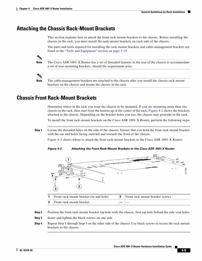
Chapter 4 Cisco ASR 1001-X Router InstallationGeneral Guidelines for Rack Installation
Attaching the Chassis Rack-Mount BracketsThis section explains how to attach the front rack-mount brackets to the chassis. Before installing the chassis in the rack, you must install the rack-mount brackets on each side of the chassis.
The parts and tools required for installing the rack-mount brackets and cable-management brackets are listed in the “Tools and Equipment” section on page 3-19.
Note The Cisco ASR 1001-X Router has a set of threaded features in the rear of the chassis to accommodate a set of rear-mounting brackets, should the requirement arise.
Note The cable-management brackets are attached to the chassis after you install the chassis rack-mount brackets on the chassis and mount the chassis in the rack.
Chassis Front Rack-Mount BracketsDetermine where in the rack you want the chassis to be mounted. If you are mounting more than one chassis in the rack, then start from the bottom up or the center of the rack. Figure 4-2 shows the brackets attached to the chassis. Depending on the bracket holes you use, the chassis may protrude in the rack.
To install the front rack-mount brackets on the Cisco ASR 1001-X Router, perform the following steps:
Step 1 Locate the threaded holes on the side of the chassis. Ensure that you hold the front rack-mount bracket with the ear and holes facing outward and towards the front of the chassis.
Figure 4-2 shows where to attach the front rack-mount brackets to the Cisco ASR 1001-X Router.
Figure 4-2 Attaching the Front Rack-Mount Brackets to the Cisco ASR 1001-X Router
Step 2 Position the front rack-mount bracket top hole with the chassis, first top hole behind the side vent holes.
Step 3 Insert and tighten the black screws on one side.
Step 4 Repeat Step 1 through Step 3 on the other side of the chassis. Use black screws to secure the rack-mount brackets to the chassis.
1 Front rack-mount bracket ear and holes 3 Front rack-mount bracket screws
2 Front rack-mount bracket — —
23
1
3710
82
4-5Cisco ASR 1001-X Router Hardware Installation Guide
OL-32376-02
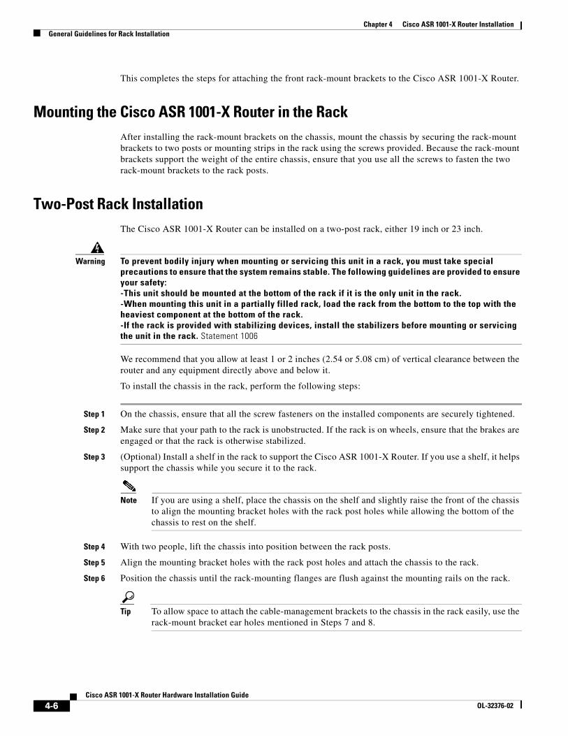
Chapter 4 Cisco ASR 1001-X Router InstallationGeneral Guidelines for Rack Installation
This completes the steps for attaching the front rack-mount brackets to the Cisco ASR 1001-X Router.
Mounting the Cisco ASR 1001-X Router in the RackAfter installing the rack-mount brackets on the chassis, mount the chassis by securing the rack-mount brackets to two posts or mounting strips in the rack using the screws provided. Because the rack-mount brackets support the weight of the entire chassis, ensure that you use all the screws to fasten the two rack-mount brackets to the rack posts.
Two-Post Rack InstallationThe Cisco ASR 1001-X Router can be installed on a two-post rack, either 19 inch or 23 inch.
Warning To prevent bodily injury when mounting or servicing this unit in a rack, you must take special precautions to ensure that the system remains stable. The following guidelines are provided to ensure your safety:-This unit should be mounted at the bottom of the rack if it is the only unit in the rack.-When mounting this unit in a partially filled rack, load the rack from the bottom to the top with the heaviest component at the bottom of the rack.-If the rack is provided with stabilizing devices, install the stabilizers before mounting or servicing the unit in the rack. Statement 1006
We recommend that you allow at least 1 or 2 inches (2.54 or 5.08 cm) of vertical clearance between the router and any equipment directly above and below it.
To install the chassis in the rack, perform the following steps:
Step 1 On the chassis, ensure that all the screw fasteners on the installed components are securely tightened.
Step 2 Make sure that your path to the rack is unobstructed. If the rack is on wheels, ensure that the brakes are engaged or that the rack is otherwise stabilized.
Step 3 (Optional) Install a shelf in the rack to support the Cisco ASR 1001-X Router. If you use a shelf, it helps support the chassis while you secure it to the rack.
Note If you are using a shelf, place the chassis on the shelf and slightly raise the front of the chassis to align the mounting bracket holes with the rack post holes while allowing the bottom of the chassis to rest on the shelf.
Step 4 With two people, lift the chassis into position between the rack posts.
Step 5 Align the mounting bracket holes with the rack post holes and attach the chassis to the rack.
Step 6 Position the chassis until the rack-mounting flanges are flush against the mounting rails on the rack.
Tip To allow space to attach the cable-management brackets to the chassis in the rack easily, use the rack-mount bracket ear holes mentioned in Steps 7 and 8.
4-6Cisco ASR 1001-X Router Hardware Installation Guide
OL-32376-02
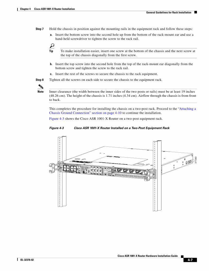
Chapter 4 Cisco ASR 1001-X Router InstallationGeneral Guidelines for Rack Installation
Step 7 Hold the chassis in position against the mounting rails in the equipment rack and follow these steps:
a. Insert the bottom screw into the second hole up from the bottom of the rack-mount ear and use a hand-held screwdriver to tighten the screw to the rack rail.
Tip To make installation easier, insert one screw at the bottom of the chassis and the next screw at the top of the chassis diagonally from the first screw.
b. Insert the top screw into the second hole from the top of the rack-mount ear diagonally from the bottom screw and tighten the screw to the rack rail.
c. Insert the rest of the screws to secure the chassis to the rack equipment.
Step 8 Tighten all the screws on each side to secure the chassis to the equipment rack.
Note Inner clearance (the width between the inner sides of the two posts or rails) must be at least 19 inches (48.26 cm). The height of the chassis is 1.71 inches (4.34 cm). Airflow through the chassis is from front to back.
This completes the procedure for installing the chassis on a two-post rack. Proceed to the “Attaching a Chassis Ground Connection” section on page 4-10 to continue the installation.
Figure 4-3 shows the Cisco ASR 1001-X Router on a two-post equipment rack.
Figure 4-3 Cisco ASR 1001-X Router Installed on a Two-Post Equipment Rack
3710
83
4-7Cisco ASR 1001-X Router Hardware Installation Guide
OL-32376-02
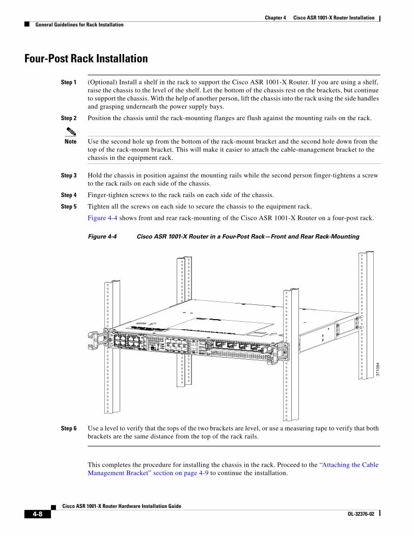
Chapter 4 Cisco ASR 1001-X Router InstallationGeneral Guidelines for Rack Installation
Four-Post Rack Installation
Step 1 (Optional) Install a shelf in the rack to support the Cisco ASR 1001-X Router. If you are using a shelf, raise the chassis to the level of the shelf. Let the bottom of the chassis rest on the brackets, but continue to support the chassis. With the help of another person, lift the chassis into the rack using the side handles and grasping underneath the power supply bays.
Step 2 Position the chassis until the rack-mounting flanges are flush against the mounting rails on the rack.
Note Use the second hole up from the bottom of the rack-mount bracket and the second hole down from the top of the rack-mount bracket. This will make it easier to attach the cable-management bracket to the chassis in the equipment rack.
Step 3 Hold the chassis in position against the mounting rails while the second person finger-tightens a screw to the rack rails on each side of the chassis.
Step 4 Finger-tighten screws to the rack rails on each side of the chassis.
Step 5 Tighten all the screws on each side to secure the chassis to the equipment rack.
Figure 4-4 shows front and rear rack-mounting of the Cisco ASR 1001-X Router on a four-post rack.
Figure 4-4 Cisco ASR 1001-X Router in a Four-Post Rack—Front and Rear Rack-Mounting
Step 6 Use a level to verify that the tops of the two brackets are level, or use a measuring tape to verify that both brackets are the same distance from the top of the rack rails.
This completes the procedure for installing the chassis in the rack. Proceed to the “Attaching the Cable Management Bracket” section on page 4-9 to continue the installation.
3710
84
4-8Cisco ASR 1001-X Router Hardware Installation Guide
OL-32376-02
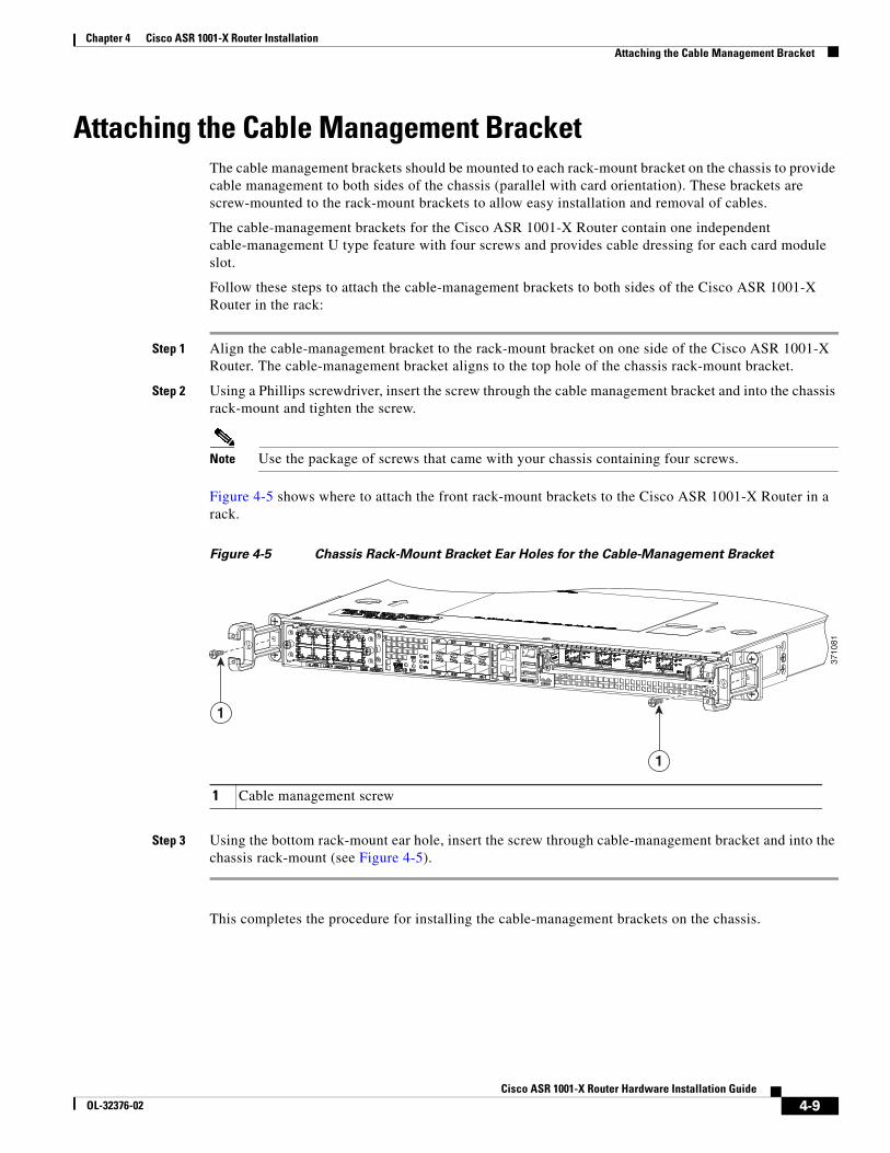
Chapter 4 Cisco ASR 1001-X Router InstallationAttaching the Cable Management Bracket
Attaching the Cable Management BracketThe cable management brackets should be mounted to each rack-mount bracket on the chassis to provide cable management to both sides of the chassis (parallel with card orientation). These brackets are screw-mounted to the rack-mount brackets to allow easy installation and removal of cables.
The cable-management brackets for the Cisco ASR 1001-X Router contain one independent cable-management U type feature with four screws and provides cable dressing for each card module slot.
Follow these steps to attach the cable-management brackets to both sides of the Cisco ASR 1001-X Router in the rack:
Step 1 Align the cable-management bracket to the rack-mount bracket on one side of the Cisco ASR 1001-X Router. The cable-management bracket aligns to the top hole of the chassis rack-mount bracket.
Step 2 Using a Phillips screwdriver, insert the screw through the cable management bracket and into the chassis rack-mount and tighten the screw.
Note Use the package of screws that came with your chassis containing four screws.
Figure 4-5 shows where to attach the front rack-mount brackets to the Cisco ASR 1001-X Router in a rack.
Figure 4-5 Chassis Rack-Mount Bracket Ear Holes for the Cable-Management Bracket
Step 3 Using the bottom rack-mount ear hole, insert the screw through cable-management bracket and into the chassis rack-mount (see Figure 4-5).
This completes the procedure for installing the cable-management brackets on the chassis.
1 Cable management screw
3710
81
1
1
4-9Cisco ASR 1001-X Router Hardware Installation Guide
OL-32376-02
Chapter 4 Cisco ASR 1001-X Router InstallationAttaching a Chassis Ground Connection
Attaching a Chassis Ground ConnectionBefore you connect power or turn on power to your chassis, you must provide an adequate chassis ground (earth) connection for the chassis in compliance with Telcordia grounding requirements. A chassis ground connector is provided on each Cisco ASR 1001-X Router. There is a stud on the side of the chassis and on the DC power supply (primary grounding stud).
Warning This equipment must be grounded. Never defeat the ground conductor or operate the equipment in the absence of a suitably installed ground conductor. Contact the appropriate electrical inspection authority or an electrician if you are uncertain that suitable grounding is available. Statement 1024
Caution The grounding wire should always be the first to be installed or connected and the last to be removed or disconnected.
Have the recommended tools and supplies available before you begin this procedure.
Recommended Tools and SuppliesThe following tools, equipment, and supplies are necessary to connect the system ground to the chassis:
• Phillips screwdriver
• 3.5-mm flat blade screwdriver (Phoenix # 1205053 or equivalent 3.5-mm flat blade)
• Dual-lug chassis ground component
• Grounding wire
4-10Cisco ASR 1001-X Router Hardware Installation Guide
OL-32376-02
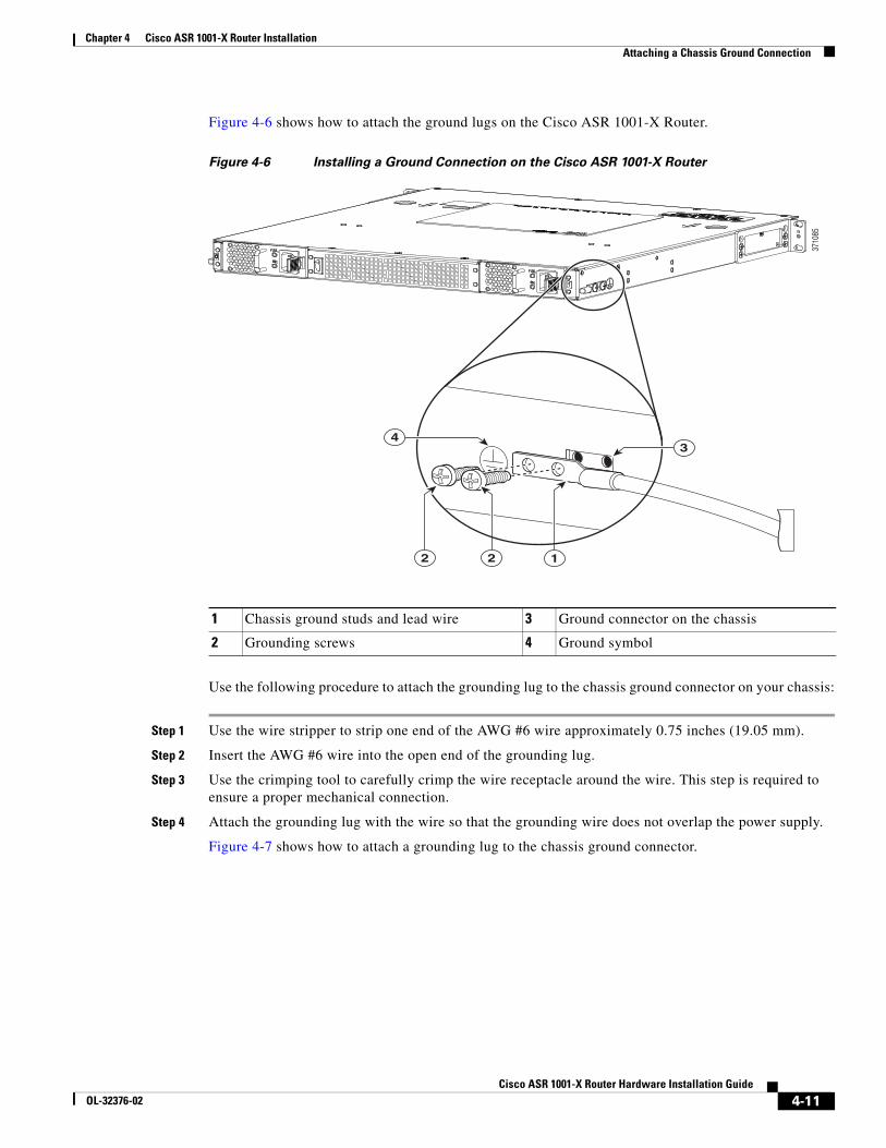
Chapter 4 Cisco ASR 1001-X Router InstallationAttaching a Chassis Ground Connection
Figure 4-6 shows how to attach the ground lugs on the Cisco ASR 1001-X Router.
Figure 4-6 Installing a Ground Connection on the Cisco ASR 1001-X Router
Use the following procedure to attach the grounding lug to the chassis ground connector on your chassis:
Step 1 Use the wire stripper to strip one end of the AWG #6 wire approximately 0.75 inches (19.05 mm).
Step 2 Insert the AWG #6 wire into the open end of the grounding lug.
Step 3 Use the crimping tool to carefully crimp the wire receptacle around the wire. This step is required to ensure a proper mechanical connection.
Step 4 Attach the grounding lug with the wire so that the grounding wire does not overlap the power supply.
Figure 4-7 shows how to attach a grounding lug to the chassis ground connector.
3710
85
12
34
2
1 Chassis ground studs and lead wire 3 Ground connector on the chassis
2 Grounding screws 4 Ground symbol
4-11Cisco ASR 1001-X Router Hardware Installation Guide
OL-32376-02
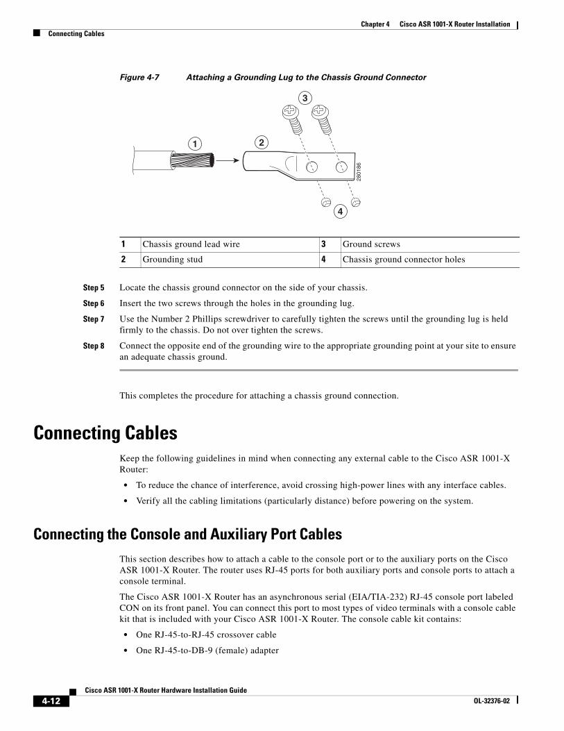
Chapter 4 Cisco ASR 1001-X Router InstallationConnecting Cables
Figure 4-7 Attaching a Grounding Lug to the Chassis Ground Connector
Step 5 Locate the chassis ground connector on the side of your chassis.
Step 6 Insert the two screws through the holes in the grounding lug.
Step 7 Use the Number 2 Phillips screwdriver to carefully tighten the screws until the grounding lug is held firmly to the chassis. Do not over tighten the screws.
Step 8 Connect the opposite end of the grounding wire to the appropriate grounding point at your site to ensure an adequate chassis ground.
This completes the procedure for attaching a chassis ground connection.
Connecting CablesKeep the following guidelines in mind when connecting any external cable to the Cisco ASR 1001-X Router:
• To reduce the chance of interference, avoid crossing high-power lines with any interface cables.
• Verify all the cabling limitations (particularly distance) before powering on the system.
Connecting the Console and Auxiliary Port CablesThis section describes how to attach a cable to the console port or to the auxiliary ports on the Cisco ASR 1001-X Router. The router uses RJ-45 ports for both auxiliary ports and console ports to attach a console terminal.
The Cisco ASR 1001-X Router has an asynchronous serial (EIA/TIA-232) RJ-45 console port labeled CON on its front panel. You can connect this port to most types of video terminals with a console cable kit that is included with your Cisco ASR 1001-X Router. The console cable kit contains:
• One RJ-45-to-RJ-45 crossover cable
• One RJ-45-to-DB-9 (female) adapter
1 Chassis ground lead wire 3 Ground screws
2 Grounding stud 4 Chassis ground connector holes
2801
86
4
1 2
3
4-12Cisco ASR 1001-X Router Hardware Installation Guide
OL-32376-02
Chapter 4 Cisco ASR 1001-X Router InstallationConnecting Cables
A crossover cable reverses pin connections from one end to the other. In other words, it connects pin 1 (at one end) to pin 8 (at the other end), pin 2 to pin 7, pin 3 to pin 6, and so on. You can identify a crossover cable by comparing the two modular ends of the cable. Hold the cable ends in your hand, side-by-side, with the tabs at the back. Ensure that the wire connected to the outside (left) pin of the left plug (pin 1) is the same color as the wire connected to the outside (right) pin of the right plug (pin 8).
Caution Both the console and auxiliary ports are asynchronous serial ports; devices connected to these ports must be capable of asynchronous transmission. To meet Class A emissions requirements, shielded cables must be used for the console and auxiliary port connectors.
Before connecting to the console interface on the router using a terminal or PC, perform the following steps:
Step 1 Before connecting a terminal to the console port, configure the terminal to match the chassis console port as follows: 9600 baud, 8 data bits, no parity, 1 stop bits (9600 8N1).
Step 2 Connect one end of the RJ-45 cable to the serial RJ-45 console port (CON) on the Cisco ASR 1000-X Router using the RJ-45 to DB-9 cable. Connect the DB-9 end to your terminal equipment.
Note For information about how to change the default settings to meet the requirements of your terminal or host, see the Cisco IOS Terminal Services Configuration Guide.
Step 3 After you establish normal router operation, you can disconnect the terminal.
Use the following procedure to connect a video terminal to the console port.
Step 4 Go to the “Connecting to the Mini USB Console Port” section on page 4-13 to continue the installation.
Connecting to the Mini USB Console PortThe USB serial console port connects directly to the USB connector of a PC using a USB Type A to 5-pin mini USB Type-B cable. The USB Console supports full speed (12Mbps) operation. The console port does not support hardware flow control.
Note • Always use shielded USB cables with a properly terminated shield. The USB serial console interface cable must not exceed 3 meters in length.
• Only one console port can be active at a time. When a cable is plugged into the USB console port, the RJ-45 port becomes inactive. Conversely, when the USB cable is removed from the USB port, the RJ-45 port becomes active.
• 4-pin mini USB Type-B connectors are easily confused with 5-pin mini USB Type-B connectors. Note that only the 5-pin mini USB Type-B is supported.
The default parameters for the console port are 9600 baud, 8 data bits, no parity, and 1 stop bit.
For operation with a Microsoft Windows OS version older than Windows 7, the Cisco Windows USB Console Driver must be installed on any PC connected to the console port. If the driver is not installed, prompts guide you through a simple installation process.
The Cisco Windows USB Console Driver allows plugging and unplugging the USB cable from the console port without affecting Windows HyperTerminal operations. No special drivers are needed for Mac OS X or Linux.
4-13Cisco ASR 1001-X Router Hardware Installation Guide
OL-32376-02
Chapter 4 Cisco ASR 1001-X Router InstallationConnecting Cables
Baud rates for the USB console port are 1200, 2400, 4800, 9600, 19200, 38400, 57600, and 115200 bps.
Management Ethernet Port Cable Connection
Caution To comply with Class A emission requirements, a shielded Ethernet cable must be used for the connection.
To use the Management Ethernet interface on the router, perform the following steps:
Step 1 Insert an Ethernet RJ-45 cable into the MGMT ETHERNET port.
Step 2 Insert the other end of the RJ-45 cable to your management device or network.
Connecting the Built-in 1 GE SFP and 10 GE SFP+ Port Cables
Built-in 1 Gigabit Ethernet Port
The six built-in Gigabit Ethernet ports (highlighted in yellow on the front panel) have six individual fiber-optic receivers that support SFP modules. Each port can send and receive traffic using the optical fiber connections.
SFP Module Connections
The small form-factor pluggable (SFP) module is an input/output (I/O) device that plugs into the six Gigabit Ethernet optical slots on the six built-in Gigabit Ethernet ports.
Note The six built-in Gigabit Ethernet ports will only accept the SFP modules listed as supported in Table 2-2. An SFP module check is run every time an SFP module is inserted into the built-in Gigabit Ethernet port and only SFP modules that pass this check will be usable. SFP modules exist for technologies other than Gigabit Ethernet and for products other than the six built-in Gigabit Ethernet ports.
Built-in 10 Gigabit Ethernet Port
The two built-in 10 Gigabit Ethernet ports (highlighted in orange on the front panel) have two individual fiber-optic receivers that support SFP+ modules. Each port can send and receive traffic using the optical fiber connections.
SFP+ Module Connections
The small form-factor pluggable (SFP+) module is an input/output (I/O) device that plugs into the 10 Gigabit Ethernet optical slots on the two built-in 10 Gigabit Ethernet ports.
4-14Cisco ASR 1001-X Router Hardware Installation Guide
OL-32376-02

Chapter 4 Cisco ASR 1001-X Router InstallationConnecting Cables
Note The two built-in 10 Gigabit Ethernet ports will only accept the SFP+ modules listed as supported in Table 2-4. An SFP module check is run every time an SFP+ module is inserted into the two built-in 10 Gigabit Ethernet ports and only SFP+ modules that pass this check will be usable. SFP+ modules exist for technologies other than Gigabit Ethernet and for products other than the two built-in 10 Gigabit Ethernet ports.
Warning The built-in 1 GE SFP modules and two 10 GE SFP+ modules of the Cisco ASR 1001-X Router share the same basic form factor and will fit in to each other’s port slots. If you accidentally install an SFP+ module into an SFP port or vice versa, the following error message is displayed:Jun 23 12:07:51.273 EST: %TRANSCEIVER-6-INSERTED: SIP0/0: transceiver module
inserted in TenGigabitEthernet0/0/0
Jun 23 12:07:53.068 EST: %TRANSCEIVER-3-NOT_SUPPORTED: SIP0/0: Detected for
transceiver module in TenGigabitEthernet0/0/0, module disabled
Jun 23 12:08:09.273 EST: %TRANSCEIVER-6-INSERTED: SIP0/0: transceiver module
inserted in GigabitEthernet0/0/1
Jun 23 12:08:10.959 EST: %TRANSCEIVER-3-INIT_FAILURE: SIP0/0: Detected for
transceiver module in GigabitEthernet0/0/1, module disabled
The generic instructions for connecting the cables for the built-in Gigabit Ethernet ports installed in the Cisco ASR 1000 Series Router are contained in the Cisco ASR 1000 Series Aggregation Services Routers SIP and SPA Hardware Installation Guide at the following location:
http://www.cisco.com/c/en/us/td/docs/interfaces_modules/shared_port_adapters/install_upgrade/ASR1000/asr_sip_spa_hw.html
Connecting the Shared Port Adapter CablesThe instructions for connecting the cables for the shared port adapter installed in the Cisco ASR 1001-X Router are contained in the Cisco ASR 1000 Series Aggregation Services Routers SIP and SPA Hardware Installation Guide at:
http://www.cisco.com/c/en/us/td/docs/interfaces_modules/shared_port_adapters/install_upgrade/ASR1000/asr_sip_spa_hw.html
4-15Cisco ASR 1001-X Router Hardware Installation Guide
OL-32376-02
Chapter 4 Cisco ASR 1001-X Router InstallationConnecting Cables
4-16Cisco ASR 1001-X Router Hardware Installation Guide
OL-32376-02
CisOL-32376-02
C H A P T E R 5
Cisco ASR 1001-X Router Power Up and Initial ConfigurationThis chapter guides you through a basic router configuration, which is sufficient for you to access your network. Complex configuration procedures are beyond the scope of this publication and can be found in the modular configuration and modular command reference publications in the Cisco IOS software configuration documentation set that corresponds to the software release installed on your Cisco hardware.
This chapter contains the following sections:
• Checking Conditions Prior to System Startup, page 5-1
• Powering Up the Cisco ASR 1001-X Router, page 5-2
• Performing the Initial Configuration on the Router, page 5-4
• Saving Your Router Configuration, page 5-13
• Verifying the Initial Configuration, page 5-14
• Powering Off the Cisco ASR 1001-X Router Safely, page 5-14
• Environmental Monitoring and Reporting Functions, page 5-15
Checking Conditions Prior to System StartupEnsure that all the card slots and compartments are closed. Install blank faceplates on empty slots. Always have power supply slots filled. If you leave a power supply slot uncovered, then you risk exposure to hazardous voltages on the power pins on the midplane.
Warning Blank faceplates and cover panels serve three important functions: they prevent exposure to hazardous voltages and currents inside the chassis; they contain electromagnetic interference (EMI) that might disrupt other equipment; and they direct the flow of cooling air through the chassis. Do not operate the system unless all cards, faceplates, front covers, and rear covers are in place. Statement 1029
Note To view the boot sequence, you must have a console connection to the Cisco ASR 1001-X Router before it powers up.
5-1co ASR 1001-X Router Hardware Installation Guide
Chapter 5 Cisco ASR 1001-X Router Power Up and Initial ConfigurationPowering Up the Cisco ASR 1001-X Router
Ensure that the following conditions are addressed before starting up the router:
• The network interface cable or the optional Fast Ethernet Management port cable is connected.
• The chassis is securely mounted and grounded.
• The power and interface cables are connected.
• Your PC with terminal emulation program (hyperTerminal or equivalent) is connected to the console port, powered up, and is configured for 9600 baud, 8 data bits, 1 stop bit, no parity, with flow control set to none.
• You have selected passwords for access control.
• Captive installation screws are tight on all removable components.
• The console terminal is turned on.
• You have determined the IP addresses for the network interfaces.
• The shared port adapter and the NIM is inserted in its slot, if applicable.
• Empty card slots are filled with card blanks. This ensures proper air flow through the chassis and electromagnetic compatibility (EMC).
Powering Up the Cisco ASR 1001-X RouterPrerequisites
Before you power on, make sure that:
• The power supply cord is plugged into the power supply inlet.
• All cables are connected.
• Your computer is powered up and connected.
You are now ready to power on the system for the first time. Follow these steps.
Step 1 Move the power switch to the ON position. Listen for the fans; you should immediately hear them operating. Ensure that the power supply LED OK is green and the FAIL LED is not illuminated.
The front-panel indicator LEDs provide power, activity, and status information useful during bootup. For more detailed information about the LEDs, see “Cisco ASR 1001-X Router LEDs” section on page 1-3.
Step 2 Observe the initialization process. When the system boot is complete (the process takes a few seconds), the Cisco ASR 1001-X Router begins to initialize.
The following is an example of what is displayed during the system boot process:
Example 5-1 Loading from ROMMON with a System Image in Bootflash
Initializing Hardware ...
System integrity status: 00000610
System Bootstrap, Version 15.4(2r)S, RELEASE SOFTWARE (fc1)Copyright (c) 1994-2014 by cisco Systems, Inc.
Current image running: Boot ROM0Last reset cause: PowerOn
ASR1001-X platform with 8388608 Kbytes of main memory
5-2Cisco ASR 1001-X Router Hardware Installation Guide
OL-32376-02
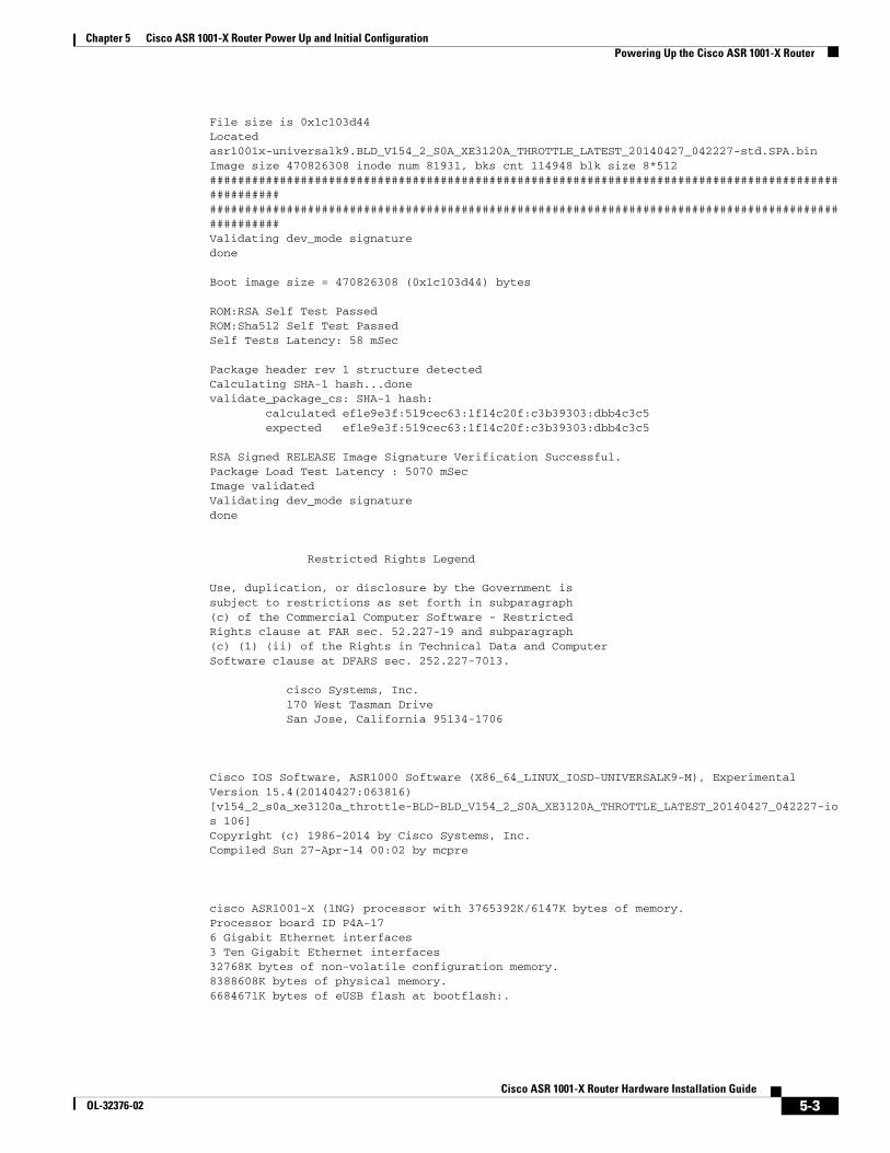
Chapter 5 Cisco ASR 1001-X Router Power Up and Initial ConfigurationPowering Up the Cisco ASR 1001-X Router
File size is 0x1c103d44Located asr1001x-universalk9.BLD_V154_2_S0A_XE3120A_THROTTLE_LATEST_20140427_042227-std.SPA.binImage size 470826308 inode num 81931, bks cnt 114948 blk size 8*512########################################################################################################################################################################################################Validating dev_mode signaturedone
Boot image size = 470826308 (0x1c103d44) bytes
ROM:RSA Self Test PassedROM:Sha512 Self Test PassedSelf Tests Latency: 58 mSec
Package header rev 1 structure detectedCalculating SHA-1 hash...donevalidate_package_cs: SHA-1 hash: calculated ef1e9e3f:519cec63:1f14c20f:c3b39303:dbb4c3c5 expected ef1e9e3f:519cec63:1f14c20f:c3b39303:dbb4c3c5
RSA Signed RELEASE Image Signature Verification Successful.Package Load Test Latency : 5070 mSecImage validatedValidating dev_mode signaturedone
Restricted Rights Legend
Use, duplication, or disclosure by the Government issubject to restrictions as set forth in subparagraph(c) of the Commercial Computer Software - RestrictedRights clause at FAR sec. 52.227-19 and subparagraph(c) (1) (ii) of the Rights in Technical Data and ComputerSoftware clause at DFARS sec. 252.227-7013.
cisco Systems, Inc. 170 West Tasman Drive San Jose, California 95134-1706
Cisco IOS Software, ASR1000 Software (X86_64_LINUX_IOSD-UNIVERSALK9-M), Experimental Version 15.4(20140427:063816) [v154_2_s0a_xe3120a_throttle-BLD-BLD_V154_2_S0A_XE3120A_THROTTLE_LATEST_20140427_042227-ios 106]Copyright (c) 1986-2014 by Cisco Systems, Inc.Compiled Sun 27-Apr-14 00:02 by mcpre
cisco ASR1001-X (1NG) processor with 3765392K/6147K bytes of memory.Processor board ID P4A-176 Gigabit Ethernet interfaces3 Ten Gigabit Ethernet interfaces32768K bytes of non-volatile configuration memory.8388608K bytes of physical memory.6684671K bytes of eUSB flash at bootflash:.
5-3Cisco ASR 1001-X Router Hardware Installation Guide
OL-32376-02
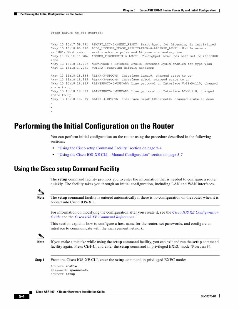
Chapter 5 Cisco ASR 1001-X Router Power Up and Initial ConfigurationPerforming the Initial Configuration on the Router
Press RETURN to get started!
*May 13 15:17:59.791: %SMART_LIC-6-AGENT_READY: Smart Agent for Licensing is initialized*May 13 15:18:00.810: %IOS_LICENSE_IMAGE_APPLICATION-6-LICENSE_LEVEL: Module name = asr1001x Next reboot level = adventerprise and License = adventerprise*May 13 15:18:03.504: %IOSXE_THROUGHPUT-6-LEVEL: Throughput level has been set to 20000000 kbps*May 13 15:18:14.767: %SPANTREE-5-EXTENDED_SYSID: Extended SysId enabled for type vlan*May 13 15:18:17.981: VOIPHA: removing default handlers
*May 13 15:18:18.838: %LINK-3-UPDOWN: Interface Lsmpi0, changed state to up*May 13 15:18:18.838: %LINK-3-UPDOWN: Interface EOBC0, changed state to up*May 13 15:18:18.839: %LINEPROTO-5-UPDOWN: Line protocol on Interface VoIP-Null0, changed state to up*May 13 15:18:18.839: %LINEPROTO-5-UPDOWN: Line protocol on Interface LI-Null0, changed state to up*May 13 15:18:18.839: %LINK-3-UPDOWN: Interface GigabitEthernet0, changed state to down...
Performing the Initial Configuration on the RouterYou can perform initial configuration on the router using the procedure described in the following sections:
• “Using the Cisco setup Command Facility” section on page 5-4
• “Using the Cisco IOS-XE CLI—Manual Configuration” section on page 5-7
Using the Cisco setup Command FacilityThe setup command facility prompts you to enter the information that is needed to configure a router quickly. The facility takes you through an initial configuration, including LAN and WAN interfaces.
Note The setup command facility is entered automatically if there is no configuration on the router when it is booted into Cisco IOS-XE.
For information on modifying the configuration after you create it, see the Cisco IOS XE Configuration Guide and the Cisco IOS XE Command References.
This section explains how to configure a host name for the router, set passwords, and configure an interface to communicate with the management network.
Note If you make a mistake while using the setup command facility, you can exit and run the setup command facility again. Press Ctrl-C, and enter the setup command in privileged EXEC mode (Router#).
Step 1 From the Cisco IOS-XE CLI, enter the setup command in privileged EXEC mode:
Router> enable Password: <password> Router# setup
5-4Cisco ASR 1001-X Router Hardware Installation Guide
OL-32376-02
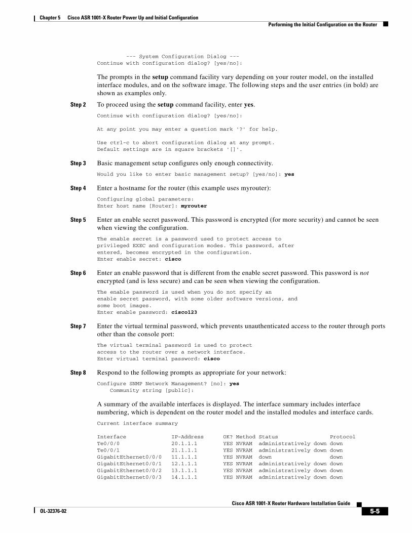
Chapter 5 Cisco ASR 1001-X Router Power Up and Initial ConfigurationPerforming the Initial Configuration on the Router
--- System Configuration Dialog ---Continue with configuration dialog? [yes/no]:
The prompts in the setup command facility vary depending on your router model, on the installed interface modules, and on the software image. The following steps and the user entries (in bold) are shown as examples only.
Step 2 To proceed using the setup command facility, enter yes.
Continue with configuration dialog? [yes/no]:
At any point you may enter a question mark '?' for help.
Use ctrl-c to abort configuration dialog at any prompt.Default settings are in square brackets '[]'.
Step 3 Basic management setup configures only enough connectivity.
Would you like to enter basic management setup? [yes/no]: yes
Step 4 Enter a hostname for the router (this example uses myrouter):
Configuring global parameters:Enter host name [Router]: myrouter
Step 5 Enter an enable secret password. This password is encrypted (for more security) and cannot be seen when viewing the configuration.
The enable secret is a password used to protect access toprivileged EXEC and configuration modes. This password, afterentered, becomes encrypted in the configuration.Enter enable secret: cisco
Step 6 Enter an enable password that is different from the enable secret password. This password is not encrypted (and is less secure) and can be seen when viewing the configuration.
The enable password is used when you do not specify anenable secret password, with some older software versions, andsome boot images.Enter enable password: cisco123
Step 7 Enter the virtual terminal password, which prevents unauthenticated access to the router through ports other than the console port:
The virtual terminal password is used to protectaccess to the router over a network interface.Enter virtual terminal password: cisco
Step 8 Respond to the following prompts as appropriate for your network:
Configure SNMP Network Management? [no]: yes Community string [public]:
A summary of the available interfaces is displayed. The interface summary includes interface numbering, which is dependent on the router model and the installed modules and interface cards.
Current interface summary
Interface IP-Address OK? Method Status ProtocolTe0/0/0 20.1.1.1 YES NVRAM administratively down down Te0/0/1 21.1.1.1 YES NVRAM administratively down down GigabitEthernet0/0/0 11.1.1.1 YES NVRAM down down GigabitEthernet0/0/1 12.1.1.1 YES NVRAM administratively down down GigabitEthernet0/0/2 13.1.1.1 YES NVRAM administratively down down GigabitEthernet0/0/3 14.1.1.1 YES NVRAM administratively down down
5-5Cisco ASR 1001-X Router Hardware Installation Guide
OL-32376-02
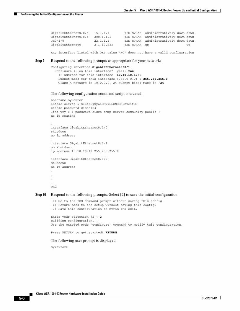
Chapter 5 Cisco ASR 1001-X Router Power Up and Initial ConfigurationPerforming the Initial Configuration on the Router
GigabitEthernet0/0/4 15.1.1.1 YES NVRAM administratively down down GigabitEthernet0/0/5 200.1.1.1 YES NVRAM administratively down down Te0/1/0 22.1.1.1 YES NVRAM administratively down down GigabitEthernet0 2.1.12.233 YES NVRAM up up
Any interface listed with OK? value "NO" does not have a valid configuration
Step 9 Respond to the following prompts as appropriate for your network:
Configuring interface GigabitEthernet0/0/1: Configure IP on this interface? [yes]: yes IP address for this interface [10.10.10.12]: Subnet mask for this interface [255.0.0.0] : 255.255.255.0 Class A network is 10.0.0.0, 24 subnet bits; mask is /24
The following configuration command script is created:
hostname myrouterenable secret 5 $1$t/Dj$yAeGKviLLZNOBX0b9eifO0enable password cisco123 line vty 0 4 password cisco snmp-server community public !no ip routing
!interface GigabitEthernet0/0/0shutdownno ip address!interface GigabitEthernet0/0/1no shutdownip address 10.10.10.12 255.255.255.0!interface GigabitEthernet0/0/2shutdownno ip address!...end
Step 10 Respond to the following prompts. Select [2] to save the initial configuration.
[0] Go to the IOS command prompt without saving this config.[1] Return back to the setup without saving this config.[2] Save this configuration to nvram and exit.
Enter your selection [2]: 2Building configuration...Use the enabled mode 'configure' command to modify this configuration.
Press RETURN to get started! RETURN
The following user prompt is displayed:
myrouter>
5-6Cisco ASR 1001-X Router Hardware Installation Guide
OL-32376-02
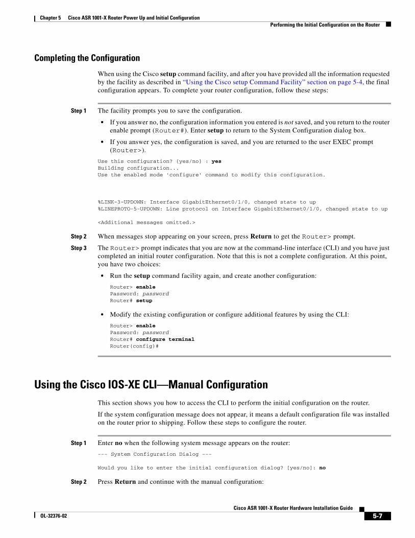
Chapter 5 Cisco ASR 1001-X Router Power Up and Initial ConfigurationPerforming the Initial Configuration on the Router
Completing the Configuration
When using the Cisco setup command facility, and after you have provided all the information requested by the facility as described in “Using the Cisco setup Command Facility” section on page 5-4, the final configuration appears. To complete your router configuration, follow these steps:
Step 1 The facility prompts you to save the configuration.
• If you answer no, the configuration information you entered is not saved, and you return to the router enable prompt (Router#). Enter setup to return to the System Configuration dialog box.
• If you answer yes, the configuration is saved, and you are returned to the user EXEC prompt (Router>).
Use this configuration? {yes/no} : yesBuilding configuration...Use the enabled mode 'configure' command to modify this configuration.
%LINK-3-UPDOWN: Interface GigabitEthernet0/1/0, changed state to up%LINEPROTO-5-UPDOWN: Line protocol on Interface GigabitEthernet0/1/0, changed state to up
<Additional messages omitted.>
Step 2 When messages stop appearing on your screen, press Return to get the Router> prompt.
Step 3 The Router> prompt indicates that you are now at the command-line interface (CLI) and you have just completed an initial router configuration. Note that this is not a complete configuration. At this point, you have two choices:
• Run the setup command facility again, and create another configuration:
Router> enablePassword: passwordRouter# setup
• Modify the existing configuration or configure additional features by using the CLI:
Router> enablePassword: passwordRouter# configure terminalRouter(config)#
Using the Cisco IOS-XE CLI—Manual ConfigurationThis section shows you how to access the CLI to perform the initial configuration on the router.
If the system configuration message does not appear, it means a default configuration file was installed on the router prior to shipping. Follow these steps to configure the router.
Step 1 Enter no when the following system message appears on the router:
--- System Configuration Dialog ---
Would you like to enter the initial configuration dialog? [yes/no]: no
Step 2 Press Return and continue with the manual configuration:
5-7Cisco ASR 1001-X Router Hardware Installation Guide
OL-32376-02
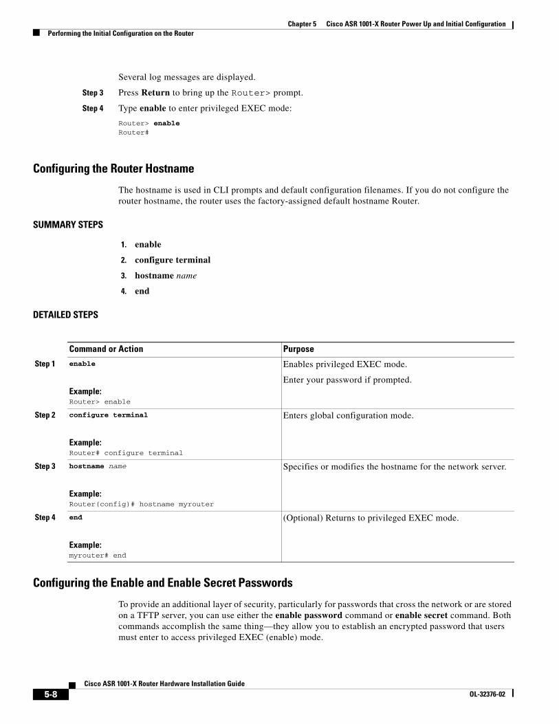
Chapter 5 Cisco ASR 1001-X Router Power Up and Initial ConfigurationPerforming the Initial Configuration on the Router
Several log messages are displayed.
Step 3 Press Return to bring up the Router> prompt.
Step 4 Type enable to enter privileged EXEC mode:
Router> enable Router#
Configuring the Router Hostname
The hostname is used in CLI prompts and default configuration filenames. If you do not configure the router hostname, the router uses the factory-assigned default hostname Router.
SUMMARY STEPS
1. enable
2. configure terminal
3. hostname name
4. end
DETAILED STEPS
Configuring the Enable and Enable Secret Passwords
To provide an additional layer of security, particularly for passwords that cross the network or are stored on a TFTP server, you can use either the enable password command or enable secret command. Both commands accomplish the same thing—they allow you to establish an encrypted password that users must enter to access privileged EXEC (enable) mode.
Command or Action Purpose
Step 1 enable
Example:Router> enable
Enables privileged EXEC mode.
Enter your password if prompted.
Step 2 configure terminal
Example:Router# configure terminal
Enters global configuration mode.
Step 3 hostname name
Example:Router(config)# hostname myrouter
Specifies or modifies the hostname for the network server.
Step 4 end
Example:myrouter# end
(Optional) Returns to privileged EXEC mode.
5-8Cisco ASR 1001-X Router Hardware Installation Guide
OL-32376-02
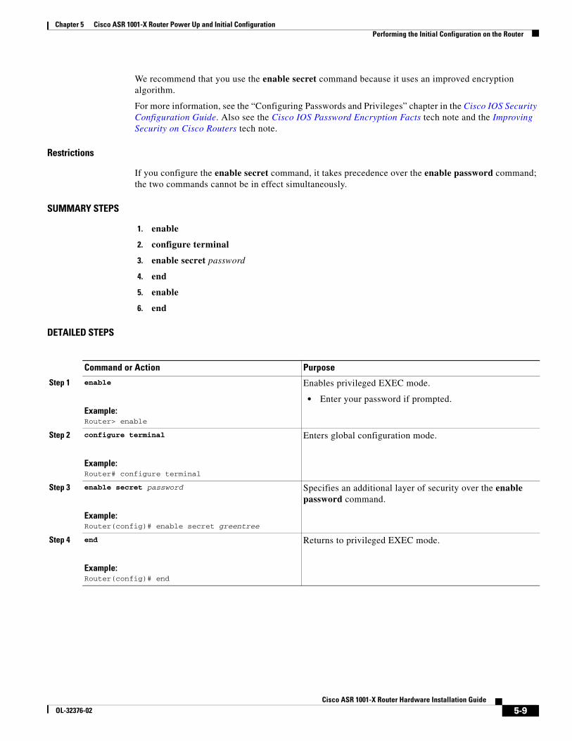
Chapter 5 Cisco ASR 1001-X Router Power Up and Initial ConfigurationPerforming the Initial Configuration on the Router
We recommend that you use the enable secret command because it uses an improved encryption algorithm.
For more information, see the “Configuring Passwords and Privileges” chapter in the Cisco IOS Security Configuration Guide. Also see the Cisco IOS Password Encryption Facts tech note and the Improving Security on Cisco Routers tech note.
Restrictions
If you configure the enable secret command, it takes precedence over the enable password command; the two commands cannot be in effect simultaneously.
SUMMARY STEPS
1. enable
2. configure terminal
3. enable secret password
4. end
5. enable
6. end
DETAILED STEPS
Command or Action Purpose
Step 1 enable
Example:Router> enable
Enables privileged EXEC mode.
• Enter your password if prompted.
Step 2 configure terminal
Example:Router# configure terminal
Enters global configuration mode.
Step 3 enable secret password
Example:Router(config)# enable secret greentree
Specifies an additional layer of security over the enable password command.
Step 4 end
Example:Router(config)# end
Returns to privileged EXEC mode.
5-9Cisco ASR 1001-X Router Hardware Installation Guide
OL-32376-02
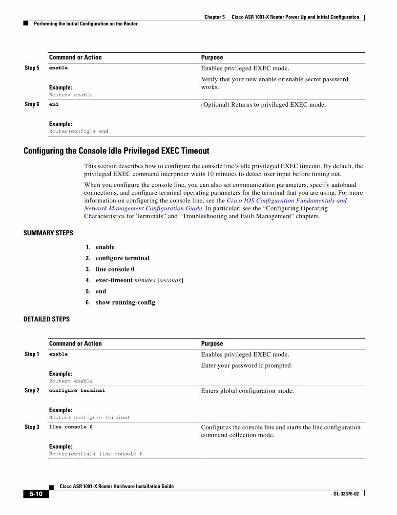
Chapter 5 Cisco ASR 1001-X Router Power Up and Initial ConfigurationPerforming the Initial Configuration on the Router
Configuring the Console Idle Privileged EXEC Timeout
This section describes how to configure the console line’s idle privileged EXEC timeout. By default, the privileged EXEC command interpreter waits 10 minutes to detect user input before timing out.
When you configure the console line, you can also set communication parameters, specify autobaud connections, and configure terminal operating parameters for the terminal that you are using. For more information on configuring the console line, see the Cisco IOS Configuration Fundamentals and Network Management Configuration Guide. In particular, see the “Configuring Operating Characteristics for Terminals” and “Troubleshooting and Fault Management” chapters.
SUMMARY STEPS
1. enable
2. configure terminal
3. line console 0
4. exec-timeout minutes [seconds]
5. end
6. show running-config
DETAILED STEPS
Step 5 enable
Example:Router> enable
Enables privileged EXEC mode.
Verify that your new enable or enable secret password works.
Step 6 end
Example:Router(config)# end
(Optional) Returns to privileged EXEC mode.
Command or Action Purpose
Command or Action Purpose
Step 1 enable
Example:Router> enable
Enables privileged EXEC mode.
Enter your password if prompted.
Step 2 configure terminal
Example:Router# configure terminal
Enters global configuration mode.
Step 3 line console 0
Example:Router(config)# line console 0
Configures the console line and starts the line configuration command collection mode.
5-10Cisco ASR 1001-X Router Hardware Installation Guide
OL-32376-02
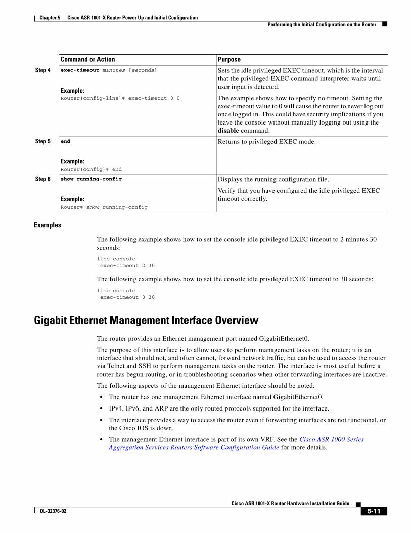
Chapter 5 Cisco ASR 1001-X Router Power Up and Initial ConfigurationPerforming the Initial Configuration on the Router
Examples
The following example shows how to set the console idle privileged EXEC timeout to 2 minutes 30 seconds:
line console exec-timeout 2 30
The following example shows how to set the console idle privileged EXEC timeout to 30 seconds:
line console exec-timeout 0 30
Gigabit Ethernet Management Interface OverviewThe router provides an Ethernet management port named GigabitEthernet0.
The purpose of this interface is to allow users to perform management tasks on the router; it is an interface that should not, and often cannot, forward network traffic, but can be used to access the router via Telnet and SSH to perform management tasks on the router. The interface is most useful before a router has begun routing, or in troubleshooting scenarios when other forwarding interfaces are inactive.
The following aspects of the management Ethernet interface should be noted:
• The router has one management Ethernet interface named GigabitEthernet0.
• IPv4, IPv6, and ARP are the only routed protocols supported for the interface.
• The interface provides a way to access the router even if forwarding interfaces are not functional, or the Cisco IOS is down.
• The management Ethernet interface is part of its own VRF. See the Cisco ASR 1000 Series Aggregation Services Routers Software Configuration Guide for more details.
Step 4 exec-timeout minutes [seconds]
Example:Router(config-line)# exec-timeout 0 0
Sets the idle privileged EXEC timeout, which is the interval that the privileged EXEC command interpreter waits until user input is detected.
The example shows how to specify no timeout. Setting the exec-timeout value to 0 will cause the router to never log out once logged in. This could have security implications if you leave the console without manually logging out using the disable command.
Step 5 end
Example:Router(config)# end
Returns to privileged EXEC mode.
Step 6 show running-config
Example:Router# show running-config
Displays the running configuration file.
Verify that you have configured the idle privileged EXEC timeout correctly.
Command or Action Purpose
5-11Cisco ASR 1001-X Router Hardware Installation Guide
OL-32376-02
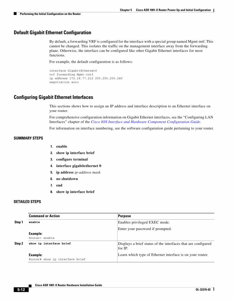
Chapter 5 Cisco ASR 1001-X Router Power Up and Initial ConfigurationPerforming the Initial Configuration on the Router
Default Gigabit Ethernet Configuration
By default, a forwarding VRF is configured for the interface with a special group named Mgmt-intf. This cannot be changed. This isolates the traffic on the management interface away from the forwarding plane. Otherwise, the interface can be configured like other Gigabit Ethernet interfaces for most functions.
For example, the default configuration is as follows:
interface GigabitEthernet0 vrf forwarding Mgmt-intf ip address 172.18.77.212 255.255.255.240 negotiation auto
Configuring Gigabit Ethernet Interfaces
This sections shows how to assign an IP address and interface description to an Ethernet interface on your router.
For comprehensive configuration information on Gigabit Ethernet interfaces, see the “Configuring LAN Interfaces” chapter of the Cisco IOS Interface and Hardware Component Configuration Guide.
For information on interface numbering, see the software configuration guide pertaining to your router.
SUMMARY STEPS
1. enable
2. show ip interface brief
3. configure terminal
4. interface gigabitethernet 0
5. ip address ip-address mask
6. no shutdown
7. end
8. show ip interface brief
DETAILED STEPS
Command or Action Purpose
Step 1 enable
Example:Router> enable
Enables privileged EXEC mode.
Enter your password if prompted.
Step 2 show ip interface brief
Example:Router# show ip interface brief
Displays a brief status of the interfaces that are configured for IP.
Learn which type of Ethernet interface is on your router.
5-12Cisco ASR 1001-X Router Hardware Installation Guide
OL-32376-02
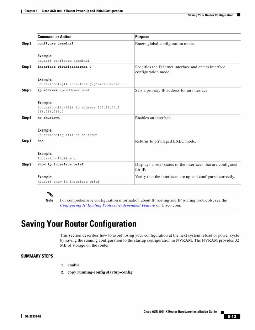
Chapter 5 Cisco ASR 1001-X Router Power Up and Initial ConfigurationSaving Your Router Configuration
Note For comprehensive configuration information about IP routing and IP routing protocols, see the Configuring IP Routing Protocol-Independent Feature on Cisco.com.
Saving Your Router ConfigurationThis section describes how to avoid losing your configuration at the next system reload or power cycle by saving the running configuration to the startup configuration in NVRAM. The NVRAM provides 32 MB of storage on the router.
SUMMARY STEPS
1. enable
2. copy running-config startup-config
Step 3 configure terminal
Example:Router# configure terminal
Enters global configuration mode.
Step 4 interface gigabitethernet 0
Example:Router(config)# interface gigabitethernet 0
Specifies the Ethernet interface and enters interface configuration mode.
Step 5 ip address ip-address mask
Example:Router(config-if)# ip address 172.16.74.3 255.255.255.0
Sets a primary IP address for an interface.
Step 6 no shutdown
Example:Router(config-if)# no shutdown
Enables an interface.
Step 7 end
Example:Router(config)# end
Returns to privileged EXEC mode.
Step 8 show ip interface brief
Example:Router# show ip interface brief
Displays a brief status of the interfaces that are configured for IP.
Verify that the interfaces are up and configured correctly.
Command or Action Purpose
5-13Cisco ASR 1001-X Router Hardware Installation Guide
OL-32376-02
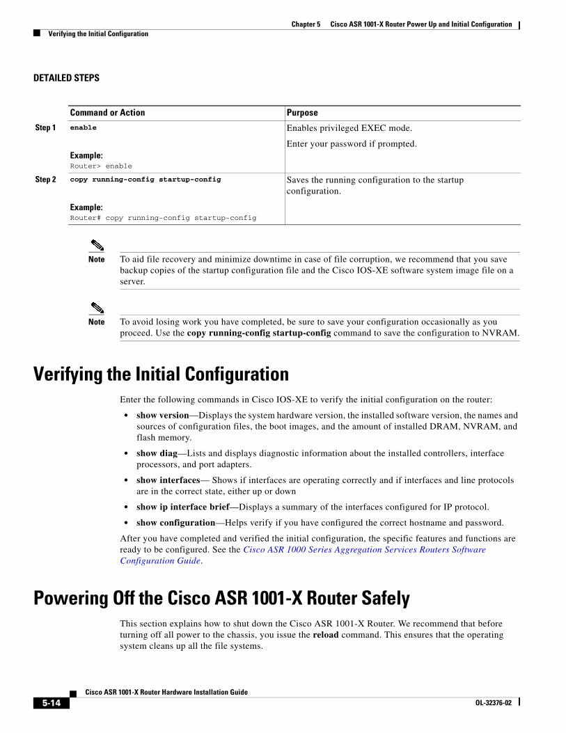
Chapter 5 Cisco ASR 1001-X Router Power Up and Initial ConfigurationVerifying the Initial Configuration
DETAILED STEPS
Note To aid file recovery and minimize downtime in case of file corruption, we recommend that you save backup copies of the startup configuration file and the Cisco IOS-XE software system image file on a server.
Note To avoid losing work you have completed, be sure to save your configuration occasionally as you proceed. Use the copy running-config startup-config command to save the configuration to NVRAM.
Verifying the Initial ConfigurationEnter the following commands in Cisco IOS-XE to verify the initial configuration on the router:
• show version—Displays the system hardware version, the installed software version, the names and sources of configuration files, the boot images, and the amount of installed DRAM, NVRAM, and flash memory.
• show diag—Lists and displays diagnostic information about the installed controllers, interface processors, and port adapters.
• show interfaces— Shows if interfaces are operating correctly and if interfaces and line protocols are in the correct state, either up or down
• show ip interface brief—Displays a summary of the interfaces configured for IP protocol.
• show configuration—Helps verify if you have configured the correct hostname and password.
After you have completed and verified the initial configuration, the specific features and functions are ready to be configured. See the Cisco ASR 1000 Series Aggregation Services Routers Software Configuration Guide.
Powering Off the Cisco ASR 1001-X Router SafelyThis section explains how to shut down the Cisco ASR 1001-X Router. We recommend that before turning off all power to the chassis, you issue the reload command. This ensures that the operating system cleans up all the file systems.
Command or Action Purpose
Step 1 enable
Example:Router> enable
Enables privileged EXEC mode.
Enter your password if prompted.
Step 2 copy running-config startup-config
Example:Router# copy running-config startup-config
Saves the running configuration to the startup configuration.
5-14Cisco ASR 1001-X Router Hardware Installation Guide
OL-32376-02
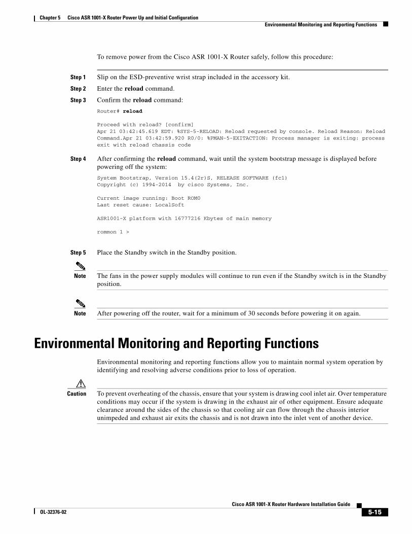
Chapter 5 Cisco ASR 1001-X Router Power Up and Initial ConfigurationEnvironmental Monitoring and Reporting Functions
To remove power from the Cisco ASR 1001-X Router safely, follow this procedure:
Step 1 Slip on the ESD-preventive wrist strap included in the accessory kit.
Step 2 Enter the reload command.
Step 3 Confirm the reload command:
Router# reload
Proceed with reload? [confirm]Apr 21 03:42:45.619 EDT: %SYS-5-RELOAD: Reload requested by console. Reload Reason: Reload Command.Apr 21 03:42:59.920 R0/0: %PMAN-5-EXITACTION: Process manager is exiting: process exit with reload chassis code
Step 4 After confirming the reload command, wait until the system bootstrap message is displayed before powering off the system:
System Bootstrap, Version 15.4(2r)S, RELEASE SOFTWARE (fc1)Copyright (c) 1994-2014 by cisco Systems, Inc.
Current image running: Boot ROM0Last reset cause: LocalSoft
ASR1001-X platform with 16777216 Kbytes of main memory
rommon 1 >
Step 5 Place the Standby switch in the Standby position.
Note The fans in the power supply modules will continue to run even if the Standby switch is in the Standby position.
Note After powering off the router, wait for a minimum of 30 seconds before powering it on again.
Environmental Monitoring and Reporting FunctionsEnvironmental monitoring and reporting functions allow you to maintain normal system operation by identifying and resolving adverse conditions prior to loss of operation.
Caution To prevent overheating of the chassis, ensure that your system is drawing cool inlet air. Over temperature conditions may occur if the system is drawing in the exhaust air of other equipment. Ensure adequate clearance around the sides of the chassis so that cooling air can flow through the chassis interior unimpeded and exhaust air exits the chassis and is not drawn into the inlet vent of another device.
5-15Cisco ASR 1001-X Router Hardware Installation Guide
OL-32376-02
Chapter 5 Cisco ASR 1001-X Router Power Up and Initial ConfigurationEnvironmental Monitoring and Reporting Functions
Cisco ASR1001-X Router Alarm MonitoringThe Cisco ASR 1001-X Router displays the CRIT, MAJ, and MIN alarm indicator LEDs. The three system alarm LEDs on the Cisco ASR 1001-X Router provide visual alarm notification in the router. These LEDs indicate router status at all times, but you must directly observe these LEDs to become aware of a router alarm condition. Additionally, you can use the show facility-alarm status command to view the alarms.
Router# show facility-alarm status
System Totals Critical: 4 Major: 0 Minor: 0
Source Time Severity Description [Index]------ ------ -------- -------------------Power Supply Module 1 Mar 12 2014 09:05:21 CRITICAL Power Supply Failure [0]xcvr container 0/0/0 Mar 12 2014 09:05:42 CRITICAL Transceiver Missing - Link Down [1]xcvr container 0/0/1 Mar 12 2014 09:05:42 INFO Transceiver Missing [0]xcvr container 0/0/2 Mar 12 2014 09:05:42 CRITICAL Transceiver Missing - Link Down [1]xcvr container 0/0/3 Mar 12 2014 09:05:42 CRITICAL Transceiver Missing - Link Down [1]xcvr container 0/0/4 Mar 12 2014 09:05:42 INFO Transceiver Missing [0]xcvr container 0/0/5 Mar 12 2014 09:05:42 INFO Transceiver Missing [0]xcvr container 0/0/6 Mar 12 2014 09:05:42 INFO Transceiver Missing [0]xcvr container 0/0/7 Mar 12 2014 09:05:42 INFO Transceiver Missing [0]
Note There is no external alarm monitoring facility on the Cisco ASR 1001-X Router.
To clear a visual alarm, you must resolve the alarm condition. The clear facility-alarm command does not clear an alarm LED on the Cisco ASR 1001-X Router. For example, if a critical alarm LED is illuminated because an active SPA was removed without a graceful deactivation of the SPA, the only way to resolve that alarm is to replace the SPA.
Environmental MonitoringThe environmental monitoring functions use sensors to monitor the temperature of the cooling air as it moves through the chassis.
The local power supplies provide the ability to monitor:
• Input and output voltage
• Output current
• Outlet temperature
The Cisco ASR 1001-X Router is expected to meet the following environmental operating conditions:
• Operating Temperature Nominal: 0° to 40°C
• Operating Temperature Short Term: 0° to +55°C
• Operating Humidity Nominal (relative humidity): 10 to 90% relative
• Operating Humidity Short Term: 5 to 90% relative
• Operating Altitude: –500 to 10,000 feet
• DC Input Range: –40 to –72 VDC
5-16Cisco ASR 1001-X Router Hardware Installation Guide
OL-32376-02
Chapter 5 Cisco ASR 1001-X Router Power Up and Initial ConfigurationEnvironmental Monitoring and Reporting Functions
• AC Input Range: 85 to 264 VAC
In addition, the power supplies monitor internal power supply temperatures and voltages. A power supply is either within tolerance (normal) or out of tolerance (critical). If an internal power supply temperature or voltage reaches a critical level, the power supply shuts down without any interaction with the system processor.
The environmental monitoring functions use the following levels of status conditions to monitor the system:
• Normal—All monitored parameters are within normal tolerances.
• Warning—The system has exceeded a specified threshold. The system continues to operate, but operator action is recommended to bring the system back to a normal state.
• Critical—An out-of-tolerance temperature or voltage condition exists. The system continues to operate, but the system is approaching shutdown. Immediate operator action is required.
• Shutdown—Before any shutdown, the system logs the status of monitored parameters in NVRAM so that you can retrieve it later to help determine the cause of the problem.
• Power supply shutdown—The power supply detected an internal out-of-tolerance overvoltage, overcurrent, or temperature condition and shut itself down. All DC power remains disabled until you toggle the power switch.
Note The Cisco ASR 1001-X Router does not shut down automatically during an over-temperature condition. The router will remain active irrespective of what the ambient temperature is, if the router is exposed to an extremely hot environment for a prolonged period of time, it will remain active until the hardware fails.
The facility-alarm critical exceed-action shutdown command is disabled on the Cisco ASR 1001-X Router.
The console terminal displays the following error message if you execute the facility-alarm critical exceed-action shutdown command:
Router(config)# facility-alarm critical exceed-action shutdown
Router(config)# end
Router#
*Apr 22 15:27:26.939: %CMANRPCHAIN-6-NOSHUTWARN: Shutdown not supported on this platform
*Apr 22 15:27:27.974: %SYS-5-CONFIG_I: Configured from console by console
Router#
If the air temperature exceeds a defined threshold, the system controller displays the following warning message on the console terminal:
Router#
*Apr 22 15:30:37.749: %CMRP_ENVMON-3-TEMP_WARN_CRITICAL: R0/0: cmand: WARNING: Temp: Inlet temperature sensor on R0 is in a critical state reading 81
Router#
The console terminal displays the following status if you execute the show facility-alarm status command:
Router# show facility-alarm status
System Totals Critical: 2 Major: 0 Minor: 0
Source Time Severity Description [Index]
5-17Cisco ASR 1001-X Router Hardware Installation Guide
OL-32376-02

Chapter 5 Cisco ASR 1001-X Router Power Up and Initial ConfigurationEnvironmental Monitoring and Reporting Functions
------ ------ -------- -------------------
xcvr container 0/0/1 Apr 22 2014 15:25:57 CRITICAL Transceiver Missing - Link Down [1]
Temp: Inlet R0/30 Apr 22 2014 15:30:37 CRITICAL Temp Above Normal (Shutdown) [1]
GigabitEthernet0 Apr 22 2014 15:25:42 INFO Physical Port Administrative State Down [2]
Router#
Fan FailuresFour internal fans draw cooling air into the chassis and across internal components to maintain an acceptable operating temperature. The fans are located in the center of the chassis. The fans are numbered from 0 to 3, right to left. When the system power is on, all fans should be operational. However, the system continues to operate even if a fan fails.
Use the show platform hardware slot <slot> fan status command to view the status of the fans, for example:
Router# show platform hardware slot P2 fan status
Fan group 1 speed: 60%
Fan 0: Normal
Fan 1: Normal
Fan 2: Normal
Fan 3: Fail
Reporting FunctionsThe chassis manager on the forwarding engine control processor manages the local resources of the forwarding processor. The Cisco ASR 1001-X Router displays warning messages on the console if the chassis interface-monitored parameters exceed a threshold. You can also retrieve and display environmental status reports with the following commands:
• show environment all
• show version
• show inventory
• show platform
• show platform software status control-processor
• show diag
Parameters are measured and reporting functions are updated every 60 seconds. A brief description of each of these commands follows.
The show environment all command displays temperature, voltage, fan, and power supply information.
The following is sample output from the show environment all command.
Example 5-2 show environment all Command
Router# show environment all
5-18Cisco ASR 1001-X Router Hardware Installation Guide
OL-32376-02
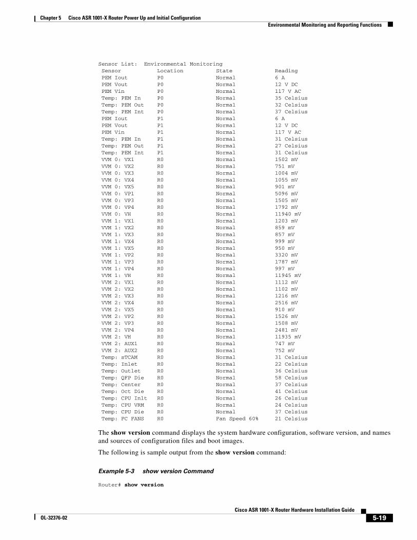
Chapter 5 Cisco ASR 1001-X Router Power Up and Initial ConfigurationEnvironmental Monitoring and Reporting Functions
Sensor List: Environmental Monitoring Sensor Location State Reading PEM Iout P0 Normal 6 A PEM Vout P0 Normal 12 V DC PEM Vin P0 Normal 117 V AC Temp: PEM In P0 Normal 35 Celsius Temp: PEM Out P0 Normal 32 Celsius Temp: PEM Int P0 Normal 37 Celsius PEM Iout P1 Normal 6 A PEM Vout P1 Normal 12 V DC PEM Vin P1 Normal 117 V AC Temp: PEM In P1 Normal 31 Celsius Temp: PEM Out P1 Normal 27 Celsius Temp: PEM Int P1 Normal 31 Celsius VVM 0: VX1 R0 Normal 1502 mV VVM 0: VX2 R0 Normal 751 mV VVM 0: VX3 R0 Normal 1004 mV VVM 0: VX4 R0 Normal 1055 mV VVM 0: VX5 R0 Normal 901 mV VVM 0: VP1 R0 Normal 5096 mV VVM 0: VP3 R0 Normal 1505 mV VVM 0: VP4 R0 Normal 1792 mV VVM 0: VH R0 Normal 11940 mV VVM 1: VX1 R0 Normal 1203 mV VVM 1: VX2 R0 Normal 859 mV VVM 1: VX3 R0 Normal 857 mV VVM 1: VX4 R0 Normal 999 mV VVM 1: VX5 R0 Normal 950 mV VVM 1: VP2 R0 Normal 3320 mV VVM 1: VP3 R0 Normal 1787 mV VVM 1: VP4 R0 Normal 997 mV VVM 1: VH R0 Normal 11945 mV VVM 2: VX1 R0 Normal 1112 mV VVM 2: VX2 R0 Normal 1102 mV VVM 2: VX3 R0 Normal 1216 mV VVM 2: VX4 R0 Normal 2516 mV VVM 2: VX5 R0 Normal 910 mV VVM 2: VP2 R0 Normal 1526 mV VVM 2: VP3 R0 Normal 1508 mV VVM 2: VP4 R0 Normal 2481 mV VVM 2: VH R0 Normal 11935 mV VVM 2: AUX1 R0 Normal 747 mV VVM 2: AUX2 R0 Normal 752 mV Temp: sTCAM R0 Normal 31 Celsius Temp: Inlet R0 Normal 22 Celsius Temp: Outlet R0 Normal 36 Celsius Temp: QFP Die R0 Normal 58 Celsius Temp: Center R0 Normal 37 Celsius Temp: Oct Die R0 Normal 41 Celsius Temp: CPU Inlt R0 Normal 26 Celsius Temp: CPU VRM R0 Normal 24 Celsius Temp: CPU Die R0 Normal 37 Celsius Temp: FC FANS R0 Fan Speed 60% 21 Celsius
The show version command displays the system hardware configuration, software version, and names and sources of configuration files and boot images.
The following is sample output from the show version command:
Example 5-3 show version Command
Router# show version
5-19Cisco ASR 1001-X Router Hardware Installation Guide
OL-32376-02
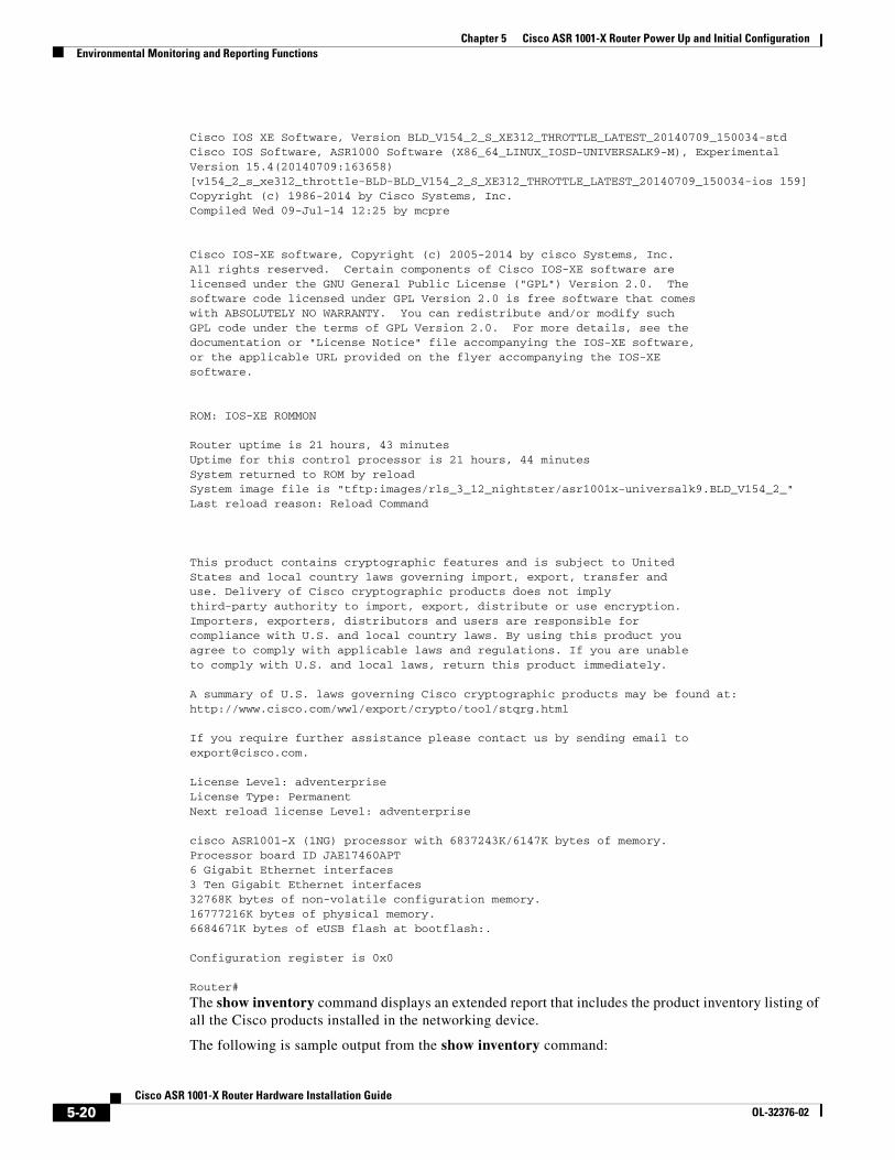
Chapter 5 Cisco ASR 1001-X Router Power Up and Initial ConfigurationEnvironmental Monitoring and Reporting Functions
Cisco IOS XE Software, Version BLD_V154_2_S_XE312_THROTTLE_LATEST_20140709_150034-stdCisco IOS Software, ASR1000 Software (X86_64_LINUX_IOSD-UNIVERSALK9-M), Experimental Version 15.4(20140709:163658) [v154_2_s_xe312_throttle-BLD-BLD_V154_2_S_XE312_THROTTLE_LATEST_20140709_150034-ios 159]Copyright (c) 1986-2014 by Cisco Systems, Inc.Compiled Wed 09-Jul-14 12:25 by mcpre
Cisco IOS-XE software, Copyright (c) 2005-2014 by cisco Systems, Inc.All rights reserved. Certain components of Cisco IOS-XE software arelicensed under the GNU General Public License ("GPL") Version 2.0. Thesoftware code licensed under GPL Version 2.0 is free software that comeswith ABSOLUTELY NO WARRANTY. You can redistribute and/or modify suchGPL code under the terms of GPL Version 2.0. For more details, see thedocumentation or "License Notice" file accompanying the IOS-XE software,or the applicable URL provided on the flyer accompanying the IOS-XEsoftware.
ROM: IOS-XE ROMMON
Router uptime is 21 hours, 43 minutesUptime for this control processor is 21 hours, 44 minutesSystem returned to ROM by reloadSystem image file is "tftp:images/rls_3_12_nightster/asr1001x-universalk9.BLD_V154_2_"Last reload reason: Reload Command
This product contains cryptographic features and is subject to UnitedStates and local country laws governing import, export, transfer anduse. Delivery of Cisco cryptographic products does not implythird-party authority to import, export, distribute or use encryption.Importers, exporters, distributors and users are responsible forcompliance with U.S. and local country laws. By using this product youagree to comply with applicable laws and regulations. If you are unableto comply with U.S. and local laws, return this product immediately.
A summary of U.S. laws governing Cisco cryptographic products may be found at:http://www.cisco.com/wwl/export/crypto/tool/stqrg.html
If you require further assistance please contact us by sending email [email protected].
License Level: adventerpriseLicense Type: PermanentNext reload license Level: adventerprise
cisco ASR1001-X (1NG) processor with 6837243K/6147K bytes of memory.Processor board ID JAE17460APT6 Gigabit Ethernet interfaces3 Ten Gigabit Ethernet interfaces32768K bytes of non-volatile configuration memory.16777216K bytes of physical memory.6684671K bytes of eUSB flash at bootflash:.
Configuration register is 0x0
Router#
The show inventory command displays an extended report that includes the product inventory listing of all the Cisco products installed in the networking device.
The following is sample output from the show inventory command:
5-20Cisco ASR 1001-X Router Hardware Installation Guide
OL-32376-02
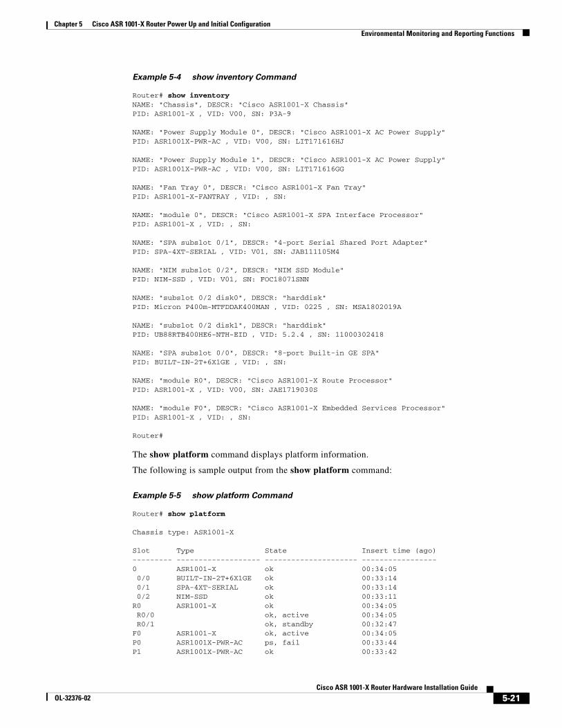
Chapter 5 Cisco ASR 1001-X Router Power Up and Initial ConfigurationEnvironmental Monitoring and Reporting Functions
Example 5-4 show inventory Command
Router# show inventoryNAME: "Chassis", DESCR: "Cisco ASR1001-X Chassis"PID: ASR1001-X , VID: V00, SN: P3A-9
NAME: "Power Supply Module 0", DESCR: "Cisco ASR1001-X AC Power Supply"PID: ASR1001X-PWR-AC , VID: V00, SN: LIT171616HJ
NAME: "Power Supply Module 1", DESCR: "Cisco ASR1001-X AC Power Supply"PID: ASR1001X-PWR-AC , VID: V00, SN: LIT171616GG
NAME: "Fan Tray 0", DESCR: "Cisco ASR1001-X Fan Tray"PID: ASR1001-X-FANTRAY , VID: , SN:
NAME: "module 0", DESCR: "Cisco ASR1001-X SPA Interface Processor"PID: ASR1001-X , VID: , SN:
NAME: "SPA subslot 0/1", DESCR: "4-port Serial Shared Port Adapter"PID: SPA-4XT-SERIAL , VID: V01, SN: JAB111105M4
NAME: "NIM subslot 0/2", DESCR: "NIM SSD Module"PID: NIM-SSD , VID: V01, SN: FOC18071SNN
NAME: "subslot 0/2 disk0", DESCR: "harddisk"PID: Micron P400m-MTFDDAK400MAN , VID: 0225 , SN: MSA1802019A
NAME: "subslot 0/2 disk1", DESCR: "harddisk"PID: UB88RTB400HE6-NTH-EID , VID: 5.2.4 , SN: 11000302418
NAME: "SPA subslot 0/0", DESCR: "8-port Built-in GE SPA"PID: BUILT-IN-2T+6X1GE , VID: , SN:
NAME: "module R0", DESCR: "Cisco ASR1001-X Route Processor"PID: ASR1001-X , VID: V00, SN: JAE1719030S
NAME: "module F0", DESCR: "Cisco ASR1001-X Embedded Services Processor"PID: ASR1001-X , VID: , SN:
Router#
The show platform command displays platform information.
The following is sample output from the show platform command:
Example 5-5 show platform Command
Router# show platform
Chassis type: ASR1001-X
Slot Type State Insert time (ago) --------- ------------------- --------------------- ----------------- 0 ASR1001-X ok 00:34:05 0/0 BUILT-IN-2T+6X1GE ok 00:33:14 0/1 SPA-4XT-SERIAL ok 00:33:14 0/2 NIM-SSD ok 00:33:11 R0 ASR1001-X ok 00:34:05 R0/0 ok, active 00:34:05 R0/1 ok, standby 00:32:47 F0 ASR1001-X ok, active 00:34:05 P0 ASR1001X-PWR-AC ps, fail 00:33:44 P1 ASR1001X-PWR-AC ok 00:33:42
5-21Cisco ASR 1001-X Router Hardware Installation Guide
OL-32376-02
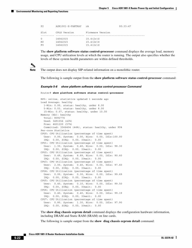
Chapter 5 Cisco ASR 1001-X Router Power Up and Initial ConfigurationEnvironmental Monitoring and Reporting Functions
P2 ASR1001-X-FANTRAY ok 00:33:47
Slot CPLD Version Firmware Version --------- ------------------- --------------------------------------- 0 14041015 15.4(2r)S R0 14041015 15.4(2r)S F0 14041015 15.4(2r)S
The show platform software status control-processor command displays the average load, memory usage, and CPU utilization levels at which the router is running. The output also specifies whether the levels of these system health parameters are within defined thresholds.
Note The output does not display SIP-related information on a monolithic router.
The following is sample output from the show platform software status control-processor command:
Example 5-6 show platform software status control-processor Command
Router# show platform software status control-processor
RP0: online, statistics updated 1 seconds agoLoad Average: healthy 1-Min: 0.00, status: healthy, under 8.00 5-Min: 0.03, status: healthy, under 8.00 15-Min: 0.07, status: healthy, under 10.00Memory (kb): healthy Total: 8092776 Used: 3491556 (43%) Free: 4601220 (57%) Committed: 3566404 (44%), status: healthy, under 95%Per-core StatisticsCPU0: CPU Utilization (percentage of time spent) User: 0.00, System: 0.00, Nice: 0.00, Idle:100.00 IRQ: 0.00, SIRQ: 0.00, IOwait: 0.00CPU1: CPU Utilization (percentage of time spent) User: 1.30, System: 0.40, Nice: 0.00, Idle: 98.30 IRQ: 0.00, SIRQ: 0.00, IOwait: 0.00CPU2: CPU Utilization (percentage of time spent) User: 0.49, System: 8.89, Nice: 0.00, Idle: 90.60 IRQ: 0.00, SIRQ: 0.00, IOwait: 0.00CPU3: CPU Utilization (percentage of time spent) User: 2.00, System: 0.40, Nice: 0.00, Idle: 97.60 IRQ: 0.00, SIRQ: 0.00, IOwait: 0.00CPU4: CPU Utilization (percentage of time spent) User: 0.00, System: 0.30, Nice: 0.00, Idle: 99.69 IRQ: 0.00, SIRQ: 0.00, IOwait: 0.00CPU5: CPU Utilization (percentage of time spent) User: 0.40, System: 0.10, Nice: 0.00, Idle: 99.50 IRQ: 0.00, SIRQ: 0.00, IOwait: 0.00CPU6: CPU Utilization (percentage of time spent) User: 0.40, System: 0.40, Nice: 0.00, Idle: 99.19 IRQ: 0.00, SIRQ: 0.00, IOwait: 0.00CPU7: CPU Utilization (percentage of time spent) User: 0.80, System: 1.30, Nice: 0.00, Idle: 97.90 IRQ: 0.00, SIRQ: 0.00, IOwait: 0.00
The show diag chassis eeprom detail command displays the configuration hardware information, including DRAM and Static RAM (SRAM) on line cards.
The following is sample output from the show diag chassis eeprom detail command:
5-22Cisco ASR 1001-X Router Hardware Installation Guide
OL-32376-02
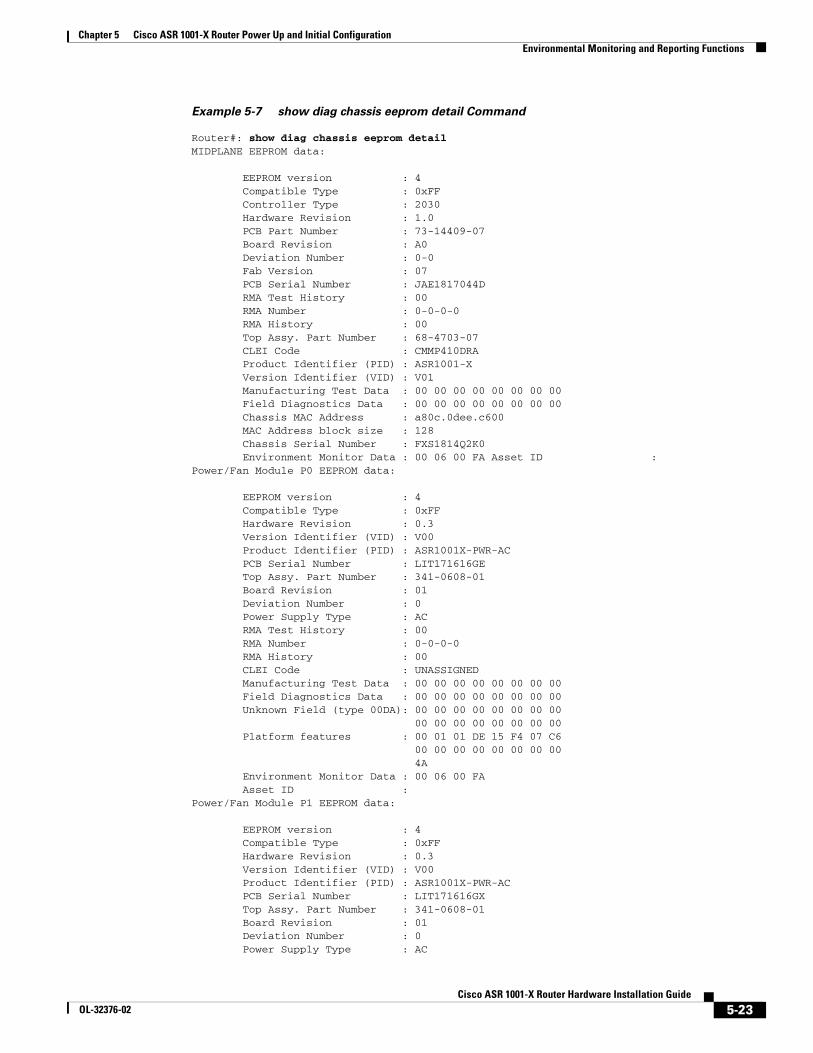
Chapter 5 Cisco ASR 1001-X Router Power Up and Initial ConfigurationEnvironmental Monitoring and Reporting Functions
Example 5-7 show diag chassis eeprom detail Command
Router#: show diag chassis eeprom detailMIDPLANE EEPROM data:
EEPROM version : 4 Compatible Type : 0xFF Controller Type : 2030 Hardware Revision : 1.0 PCB Part Number : 73-14409-07 Board Revision : A0 Deviation Number : 0-0 Fab Version : 07 PCB Serial Number : JAE1817044D RMA Test History : 00 RMA Number : 0-0-0-0 RMA History : 00 Top Assy. Part Number : 68-4703-07 CLEI Code : CMMP410DRA Product Identifier (PID) : ASR1001-X Version Identifier (VID) : V01 Manufacturing Test Data : 00 00 00 00 00 00 00 00 Field Diagnostics Data : 00 00 00 00 00 00 00 00 Chassis MAC Address : a80c.0dee.c600 MAC Address block size : 128 Chassis Serial Number : FXS1814Q2K0 Environment Monitor Data : 00 06 00 FA Asset ID :Power/Fan Module P0 EEPROM data:
EEPROM version : 4 Compatible Type : 0xFF Hardware Revision : 0.3 Version Identifier (VID) : V00 Product Identifier (PID) : ASR1001X-PWR-AC PCB Serial Number : LIT171616GE Top Assy. Part Number : 341-0608-01 Board Revision : 01 Deviation Number : 0 Power Supply Type : AC RMA Test History : 00 RMA Number : 0-0-0-0 RMA History : 00 CLEI Code : UNASSIGNED Manufacturing Test Data : 00 00 00 00 00 00 00 00 Field Diagnostics Data : 00 00 00 00 00 00 00 00 Unknown Field (type 00DA): 00 00 00 00 00 00 00 00 00 00 00 00 00 00 00 00 Platform features : 00 01 01 DE 15 F4 07 C6 00 00 00 00 00 00 00 00 4A Environment Monitor Data : 00 06 00 FA Asset ID :Power/Fan Module P1 EEPROM data:
EEPROM version : 4 Compatible Type : 0xFF Hardware Revision : 0.3 Version Identifier (VID) : V00 Product Identifier (PID) : ASR1001X-PWR-AC PCB Serial Number : LIT171616GX Top Assy. Part Number : 341-0608-01 Board Revision : 01 Deviation Number : 0 Power Supply Type : AC
5-23Cisco ASR 1001-X Router Hardware Installation Guide
OL-32376-02
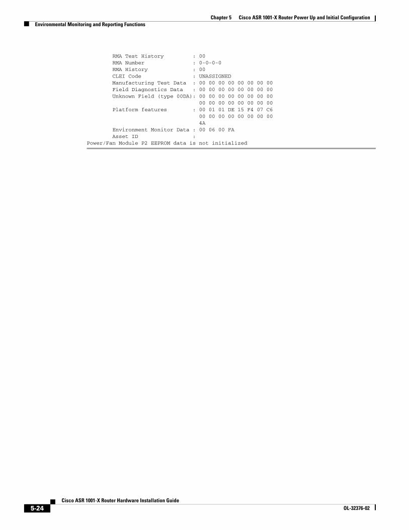
Chapter 5 Cisco ASR 1001-X Router Power Up and Initial ConfigurationEnvironmental Monitoring and Reporting Functions
RMA Test History : 00 RMA Number : 0-0-0-0 RMA History : 00 CLEI Code : UNASSIGNED Manufacturing Test Data : 00 00 00 00 00 00 00 00 Field Diagnostics Data : 00 00 00 00 00 00 00 00 Unknown Field (type 00DA): 00 00 00 00 00 00 00 00 00 00 00 00 00 00 00 00 Platform features : 00 01 01 DE 15 F4 07 C6 00 00 00 00 00 00 00 00 4A Environment Monitor Data : 00 06 00 FA Asset ID :Power/Fan Module P2 EEPROM data is not initialized
5-24Cisco ASR 1001-X Router Hardware Installation Guide
OL-32376-02
CisOL-32376-02
C H A P T E R 6
Cisco ASR 1001-X Router License VerificationThis chapter provides information about verifying the Cisco IOS license level, viewing the Cisco ASR 1001-X Router license, and configuring the throughput level.
This chapter contains the following sections:
• Viewing the Cisco IOS License Level, page 6-1
• Configuring the Throughput Level, page 6-2
• Viewing License Information, page 6-3
• Per Port Counted License (10-GE Interfaces), page 6-7
Viewing the Cisco IOS License LevelUse the show version command to determine the Cisco IOS license level in the router. For example:
Router# show version
.
.
.
License Level: adventerprise
License Type: RightToUse
Next reload license Level: adventerprise
.
.
.
Table 6-1 show version Command Output Description
Field Name Description
License Level: adventerprise Indicates the current Cisco IOS license code level.
License Type: RightToUse Indicates whether you are utilizing a permanent (purchased) license, an evaluation 60-day license, or a Right-to-Use license that would indicate that the purchase of a license is required.
Next reload license Level: adventerprise Indicates the startup configuration definition that will be used for the next reload instance.
6-1co ASR 1001-X Router Hardware Installation Guide
Chapter 6 Cisco ASR 1001-X Router License VerificationConfiguring the Throughput Level
Use the show running-config command or the show startup-config command to view the license-level information. The following example displays sample output from the show running-config command:
Router# show running-config
.
.
.
license boot level adventerprise
.
.
.
Configuring the Throughput LevelThe built-in embedded service processor of the Cisco ASR 1001-X Router supports throughputs of 2.5 Gbps (default), 5 Gbps, 10 Gbps, and 20 Gbps depending upon the software license.
You can upgrade the throughput of the ESP from 2.5 Gbps (default) to 5 Gbps, 10 Gbps, or 20 Gbps by applying a software-activated performance upgrade license and then reloading the router. You can upgrade the throughput of the ESP from any license level to another.
To determine the current throughput level of the ESP, run the show platform hardware throughput level command. The following example shows the output from this command after you apply the 20 Gbps performance upgrade license and reload the router:
Router# show platform hardware throughput levelThe current throughput level is 2000000 kb/s
After the router is reloaded, the log messages at the router startup will display the license-level and throughput-level information, for example:
%IOS_LICENSE_IMAGE_APPLICATION-6-LICENSE_LEVEL: Module name = asr1001x Next reboot level = adventerprise and License = adventerprise
%IOSXE_THROUGHPUT-6-LEVEL: Throughput level has been set to 20000000 kbps
The following message will be displayed once every 24 hours if the traffic handled by the system-forwarding plane approaches or exceeds the configured throughput license level. The configured throughput level in this example is 20 Gbps:
Exceeding 95% threshold:
*May 24 09:42:41.687 EDT: %BW_LICENSE-5-THROUGHPUT_THRESHOLD_LEVEL: F0: cpp_ha: Average throughput rate exceeded 95 percent of licensed bandwidth 20000000000 bps 25 times, sample period 300 seconds, in last 24 hours
Exceeding total bw:
*May 24 09:42:41.687 EDT: %BW_LICENSE-4-THROUGHPUT_MAX_LEVEL: F0: cpp_ha: Average throughput rate exceeded the total licensed bandwidth 20000000000 bps and dropped 8 times, sample period 300 seconds, in last 24 hours
Table 6-2 show running-config Command Output Description
Field Name Descriptionlicense boot level adventerprise Indicates the current requested Cisco lOS license
level to boot.
6-2Cisco ASR 1001-X Router Hardware Installation Guide
OL-32376-02
Chapter 6 Cisco ASR 1001-X Router License VerificationViewing License Information
For more information about the software-activated performance upgrade license, see the Software Activation Configuration Guide, Cisco IOS XE Release 3S.
Viewing License InformationUse the show license udi command to determine the Universal Device Identifier (UDI) information of your chassis. This may be required at the time of purchasing a new license. The following example displays sample output from the show license udi command:
router# show license udi
SlotID PID SN UDI
--------------------------------------------------------------------------------
*6 ASR1001-X JAE17450EUZ ASR1001-X:JAE17450EUZ
router#
You can also determine the UDI information using the show running-config command, for example:
Router# show running-config
.
.
.
license udi pid ASR1001-X sn myroutersn123
.
.
.
Use the show license all command to display all the applicable licenses in both Primary License Storage and Built In License Storage.
Note Primary License Storage stores the currently purchased and installed licenses.
The following example displays sample output from the show license all command:
router# show license all
License Store: Primary License Storage
StoreIndex: 0 Feature: interface_10g Version: 1.0
License Type: Permanent
License State: Active, In Use
Lock type: Node locked
Table 6-3 show running-config Command Output Description
Field Name Description
license udi pid ASR1001-X sn myroutersn123 License identifier information (also displayed with the show license udi command).
6-3Cisco ASR 1001-X Router Hardware Installation Guide
OL-32376-02
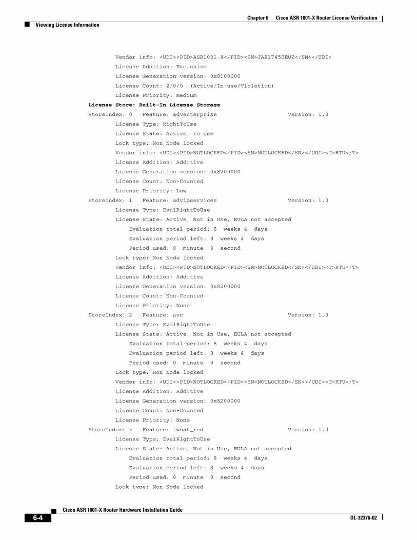
Chapter 6 Cisco ASR 1001-X Router License VerificationViewing License Information
Vendor info: <UDI><PID>ASR1001-X</PID><SN>JAE17450EUZ</SN></UDI>
License Addition: Exclusive
License Generation version: 0x8100000
License Count: 2/0/0 (Active/In-use/Violation)
License Priority: Medium
License Store: Built-In License Storage
StoreIndex: 0 Feature: adventerprise Version: 1.0
License Type: RightToUse
License State: Active, In Use
Lock type: Non Node locked
Vendor info: <UDI><PID>NOTLOCKED</PID><SN>NOTLOCKED</SN></UDI><T>RTU</T>
License Addition: Additive
License Generation version: 0x8200000
License Count: Non-Counted
License Priority: Low
StoreIndex: 1 Feature: advipservices Version: 1.0
License Type: EvalRightToUse
License State: Active, Not in Use, EULA not accepted
Evaluation total period: 8 weeks 4 days
Evaluation period left: 8 weeks 4 days
Period used: 0 minute 0 second
Lock type: Non Node locked
Vendor info: <UDI><PID>NOTLOCKED</PID><SN>NOTLOCKED</SN></UDI><T>RTU</T>
License Addition: Additive
License Generation version: 0x8200000
License Count: Non-Counted
License Priority: None
StoreIndex: 2 Feature: avc Version: 1.0
License Type: EvalRightToUse
License State: Active, Not in Use, EULA not accepted
Evaluation total period: 8 weeks 4 days
Evaluation period left: 8 weeks 4 days
Period used: 0 minute 0 second
Lock type: Non Node locked
Vendor info: <UDI><PID>NOTLOCKED</PID><SN>NOTLOCKED</SN></UDI><T>RTU</T>
License Addition: Additive
License Generation version: 0x8200000
License Count: Non-Counted
License Priority: None
StoreIndex: 3 Feature: fwnat_red Version: 1.0
License Type: EvalRightToUse
License State: Active, Not in Use, EULA not accepted
Evaluation total period: 8 weeks 4 days
Evaluation period left: 8 weeks 4 days
Period used: 0 minute 0 second
Lock type: Non Node locked
6-4Cisco ASR 1001-X Router Hardware Installation Guide
OL-32376-02
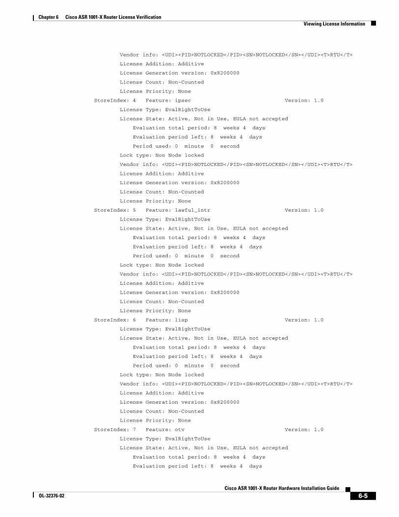
Chapter 6 Cisco ASR 1001-X Router License VerificationViewing License Information
Vendor info: <UDI><PID>NOTLOCKED</PID><SN>NOTLOCKED</SN></UDI><T>RTU</T>
License Addition: Additive
License Generation version: 0x8200000
License Count: Non-Counted
License Priority: None
StoreIndex: 4 Feature: ipsec Version: 1.0
License Type: EvalRightToUse
License State: Active, Not in Use, EULA not accepted
Evaluation total period: 8 weeks 4 days
Evaluation period left: 8 weeks 4 days
Period used: 0 minute 0 second
Lock type: Non Node locked
Vendor info: <UDI><PID>NOTLOCKED</PID><SN>NOTLOCKED</SN></UDI><T>RTU</T>
License Addition: Additive
License Generation version: 0x8200000
License Count: Non-Counted
License Priority: None
StoreIndex: 5 Feature: lawful_intr Version: 1.0
License Type: EvalRightToUse
License State: Active, Not in Use, EULA not accepted
Evaluation total period: 8 weeks 4 days
Evaluation period left: 8 weeks 4 days
Period used: 0 minute 0 second
Lock type: Non Node locked
Vendor info: <UDI><PID>NOTLOCKED</PID><SN>NOTLOCKED</SN></UDI><T>RTU</T>
License Addition: Additive
License Generation version: 0x8200000
License Count: Non-Counted
License Priority: None
StoreIndex: 6 Feature: lisp Version: 1.0
License Type: EvalRightToUse
License State: Active, Not in Use, EULA not accepted
Evaluation total period: 8 weeks 4 days
Evaluation period left: 8 weeks 4 days
Period used: 0 minute 0 second
Lock type: Non Node locked
Vendor info: <UDI><PID>NOTLOCKED</PID><SN>NOTLOCKED</SN></UDI><T>RTU</T>
License Addition: Additive
License Generation version: 0x8200000
License Count: Non-Counted
License Priority: None
StoreIndex: 7 Feature: otv Version: 1.0
License Type: EvalRightToUse
License State: Active, Not in Use, EULA not accepted
Evaluation total period: 8 weeks 4 days
Evaluation period left: 8 weeks 4 days
6-5Cisco ASR 1001-X Router Hardware Installation Guide
OL-32376-02
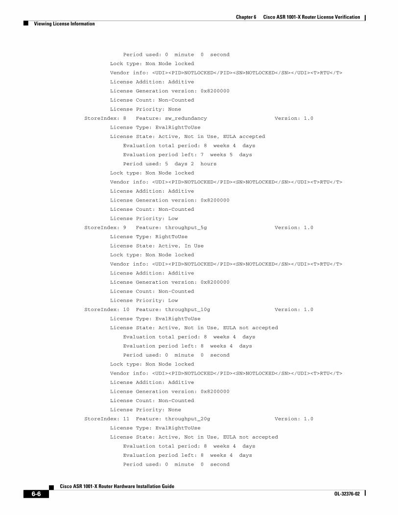
Chapter 6 Cisco ASR 1001-X Router License VerificationViewing License Information
Period used: 0 minute 0 second
Lock type: Non Node locked
Vendor info: <UDI><PID>NOTLOCKED</PID><SN>NOTLOCKED</SN></UDI><T>RTU</T>
License Addition: Additive
License Generation version: 0x8200000
License Count: Non-Counted
License Priority: None
StoreIndex: 8 Feature: sw_redundancy Version: 1.0
License Type: EvalRightToUse
License State: Active, Not in Use, EULA accepted
Evaluation total period: 8 weeks 4 days
Evaluation period left: 7 weeks 5 days
Period used: 5 days 2 hours
Lock type: Non Node locked
Vendor info: <UDI><PID>NOTLOCKED</PID><SN>NOTLOCKED</SN></UDI><T>RTU</T>
License Addition: Additive
License Generation version: 0x8200000
License Count: Non-Counted
License Priority: Low
StoreIndex: 9 Feature: throughput_5g Version: 1.0
License Type: RightToUse
License State: Active, In Use
Lock type: Non Node locked
Vendor info: <UDI><PID>NOTLOCKED</PID><SN>NOTLOCKED</SN></UDI><T>RTU</T>
License Addition: Additive
License Generation version: 0x8200000
License Count: Non-Counted
License Priority: Low
StoreIndex: 10 Feature: throughput_10g Version: 1.0
License Type: EvalRightToUse
License State: Active, Not in Use, EULA not accepted
Evaluation total period: 8 weeks 4 days
Evaluation period left: 8 weeks 4 days
Period used: 0 minute 0 second
Lock type: Non Node locked
Vendor info: <UDI><PID>NOTLOCKED</PID><SN>NOTLOCKED</SN></UDI><T>RTU</T>
License Addition: Additive
License Generation version: 0x8200000
License Count: Non-Counted
License Priority: None
StoreIndex: 11 Feature: throughput_20g Version: 1.0
License Type: EvalRightToUse
License State: Active, Not in Use, EULA not accepted
Evaluation total period: 8 weeks 4 days
Evaluation period left: 8 weeks 4 days
Period used: 0 minute 0 second
6-6Cisco ASR 1001-X Router Hardware Installation Guide
OL-32376-02
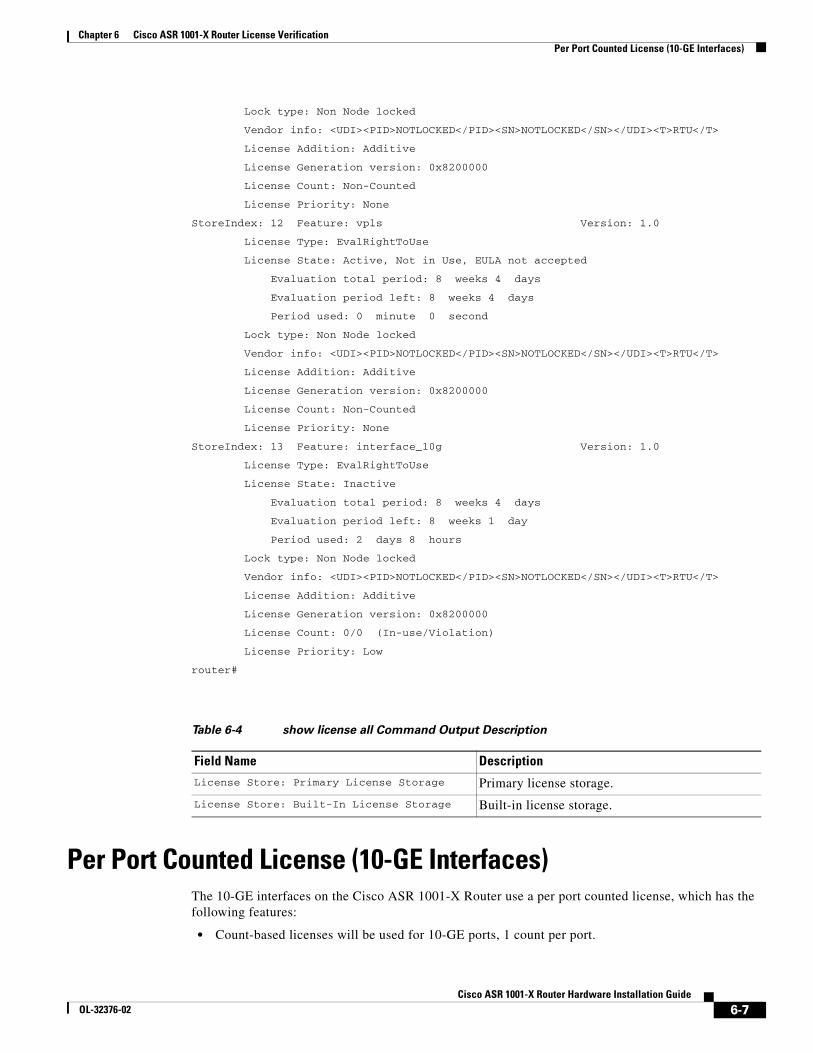
Chapter 6 Cisco ASR 1001-X Router License VerificationPer Port Counted License (10-GE Interfaces)
Lock type: Non Node locked
Vendor info: <UDI><PID>NOTLOCKED</PID><SN>NOTLOCKED</SN></UDI><T>RTU</T>
License Addition: Additive
License Generation version: 0x8200000
License Count: Non-Counted
License Priority: None
StoreIndex: 12 Feature: vpls Version: 1.0
License Type: EvalRightToUse
License State: Active, Not in Use, EULA not accepted
Evaluation total period: 8 weeks 4 days
Evaluation period left: 8 weeks 4 days
Period used: 0 minute 0 second
Lock type: Non Node locked
Vendor info: <UDI><PID>NOTLOCKED</PID><SN>NOTLOCKED</SN></UDI><T>RTU</T>
License Addition: Additive
License Generation version: 0x8200000
License Count: Non-Counted
License Priority: None
StoreIndex: 13 Feature: interface_10g Version: 1.0
License Type: EvalRightToUse
License State: Inactive
Evaluation total period: 8 weeks 4 days
Evaluation period left: 8 weeks 1 day
Period used: 2 days 8 hours
Lock type: Non Node locked
Vendor info: <UDI><PID>NOTLOCKED</PID><SN>NOTLOCKED</SN></UDI><T>RTU</T>
License Addition: Additive
License Generation version: 0x8200000
License Count: 0/0 (In-use/Violation)
License Priority: Low
router#
Per Port Counted License (10-GE Interfaces)The 10-GE interfaces on the Cisco ASR 1001-X Router use a per port counted license, which has the following features:
• Count-based licenses will be used for 10-GE ports, 1 count per port.
Table 6-4 show license all Command Output Description
Field Name DescriptionLicense Store: Primary License Storage Primary license storage.
License Store: Built-In License Storage Built-in license storage.
6-7Cisco ASR 1001-X Router Hardware Installation Guide
OL-32376-02
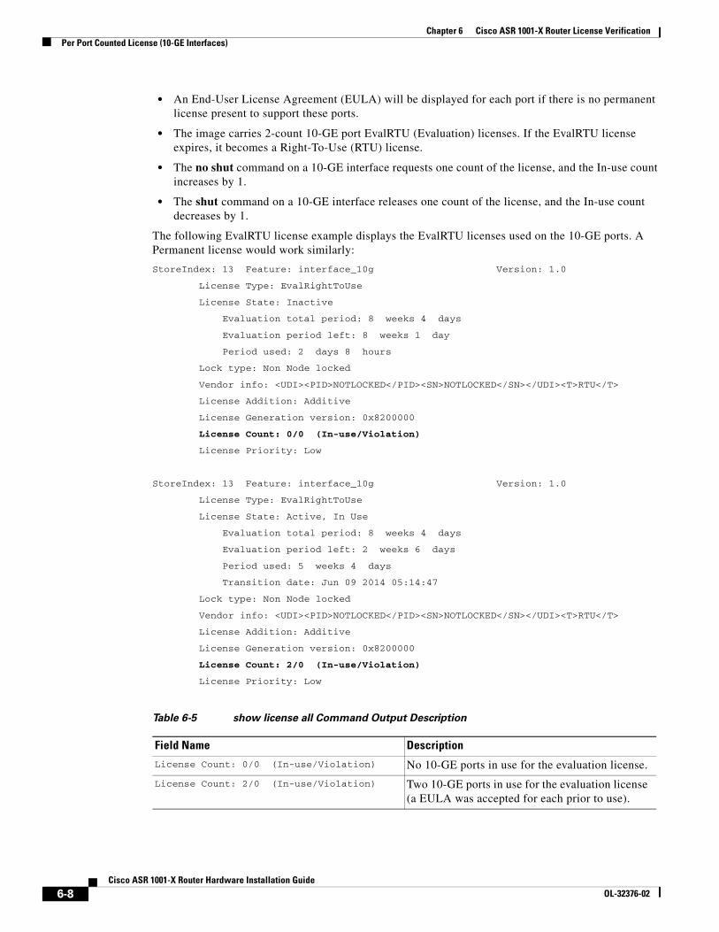
Chapter 6 Cisco ASR 1001-X Router License VerificationPer Port Counted License (10-GE Interfaces)
• An End-User License Agreement (EULA) will be displayed for each port if there is no permanent license present to support these ports.
• The image carries 2-count 10-GE port EvalRTU (Evaluation) licenses. If the EvalRTU license expires, it becomes a Right-To-Use (RTU) license.
• The no shut command on a 10-GE interface requests one count of the license, and the In-use count increases by 1.
• The shut command on a 10-GE interface releases one count of the license, and the In-use count decreases by 1.
The following EvalRTU license example displays the EvalRTU licenses used on the 10-GE ports. A Permanent license would work similarly:
StoreIndex: 13 Feature: interface_10g Version: 1.0
License Type: EvalRightToUse
License State: Inactive
Evaluation total period: 8 weeks 4 days
Evaluation period left: 8 weeks 1 day
Period used: 2 days 8 hours
Lock type: Non Node locked
Vendor info: <UDI><PID>NOTLOCKED</PID><SN>NOTLOCKED</SN></UDI><T>RTU</T>
License Addition: Additive
License Generation version: 0x8200000
License Count: 0/0 (In-use/Violation)
License Priority: Low
StoreIndex: 13 Feature: interface_10g Version: 1.0
License Type: EvalRightToUse
License State: Active, In Use
Evaluation total period: 8 weeks 4 days
Evaluation period left: 2 weeks 6 days
Period used: 5 weeks 4 days
Transition date: Jun 09 2014 05:14:47
Lock type: Non Node locked
Vendor info: <UDI><PID>NOTLOCKED</PID><SN>NOTLOCKED</SN></UDI><T>RTU</T>
License Addition: Additive
License Generation version: 0x8200000
License Count: 2/0 (In-use/Violation)
License Priority: Low
Table 6-5 show license all Command Output Description
Field Name Description
License Count: 0/0 (In-use/Violation) No 10-GE ports in use for the evaluation license.
License Count: 2/0 (In-use/Violation) Two 10-GE ports in use for the evaluation license (a EULA was accepted for each prior to use).
6-8Cisco ASR 1001-X Router Hardware Installation Guide
OL-32376-02
Chapter 6 Cisco ASR 1001-X Router License VerificationPer Port Counted License (10-GE Interfaces)
10-GE Interface Evaluation License FeaturesThe following are the features of the 10-GE Interface Evaluation license:
• There is only one 60-Day Evaluation Period countdown timer for both 10-GE ports. The timer is initiated as soon as the first of the two ports is enabled.
• A EULA will be presented, and must be accepted, the first time you enable either of the two ports in order to utilize the requested port.
• When the 60-Day Evaluation Period expires, the license automatically changes to an RTU license. As with all other RTU licenses, there is no functionality disruption or accessibility concerns following this transition. See Table 6-4.
• There can be only one active interface_10g license. Either the Permanent License or the EvalRTU License can be Active, but not both.
• As with past license implementations, the Permanent license is of higher precedence than the built-in EvalRTU license. However, when the Permanent license does not have enough port-count (that is, when the user requests both built-in 10GE ports but the Permanent License only allows for one port), the license priority changes between the Permanent and Evaluation licenses. In this case, the Evaluation License becomes Active since it can accommodate both ports. The Permanent License will automatically become Active if and when its port-count meets the user’s desired configuration.
6-9Cisco ASR 1001-X Router Hardware Installation Guide
OL-32376-02
Chapter 6 Cisco ASR 1001-X Router License VerificationPer Port Counted License (10-GE Interfaces)
6-10Cisco ASR 1001-X Router Hardware Installation Guide
OL-32376-02
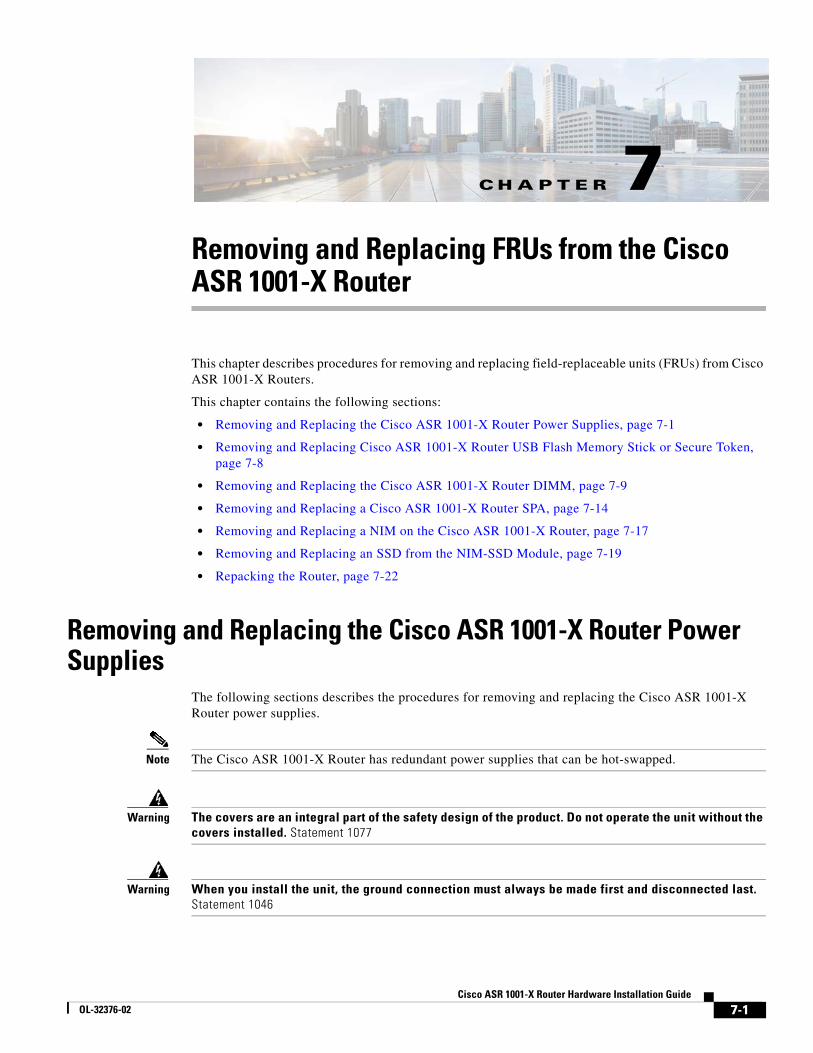
CisOL-32376-02
C H A P T E R 7
Removing and Replacing FRUs from the Cisco ASR 1001-X RouterThis chapter describes procedures for removing and replacing field-replaceable units (FRUs) from Cisco ASR 1001-X Routers.
This chapter contains the following sections:
• Removing and Replacing the Cisco ASR 1001-X Router Power Supplies, page 7-1
• Removing and Replacing Cisco ASR 1001-X Router USB Flash Memory Stick or Secure Token, page 7-8
• Removing and Replacing the Cisco ASR 1001-X Router DIMM, page 7-9
• Removing and Replacing a Cisco ASR 1001-X Router SPA, page 7-14
• Removing and Replacing a NIM on the Cisco ASR 1001-X Router, page 7-17
• Removing and Replacing an SSD from the NIM-SSD Module, page 7-19
• Repacking the Router, page 7-22
Removing and Replacing the Cisco ASR 1001-X Router Power Supplies
The following sections describes the procedures for removing and replacing the Cisco ASR 1001-X Router power supplies.
Note The Cisco ASR 1001-X Router has redundant power supplies that can be hot-swapped.
Warning The covers are an integral part of the safety design of the product. Do not operate the unit without the covers installed. Statement 1077
Warning When you install the unit, the ground connection must always be made first and disconnected last. Statement 1046
7-1co ASR 1001-X Router Hardware Installation Guide
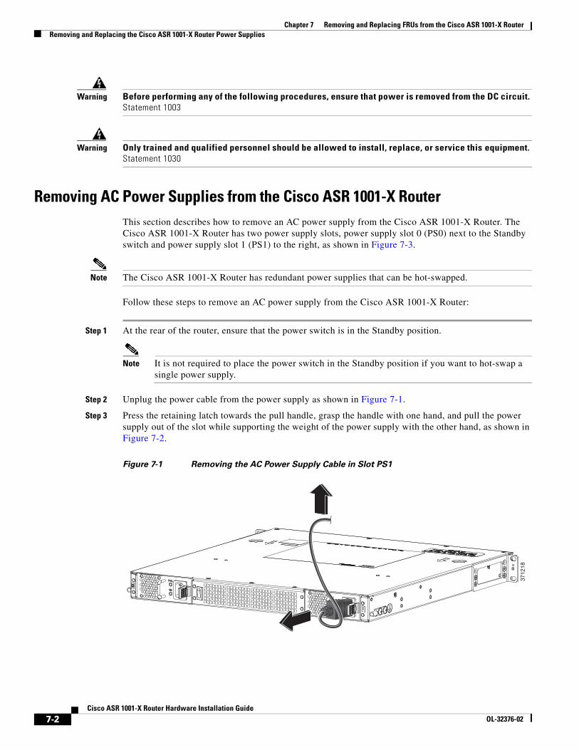
Chapter 7 Removing and Replacing FRUs from the Cisco ASR 1001-X RouterRemoving and Replacing the Cisco ASR 1001-X Router Power Supplies
Warning Before performing any of the following procedures, ensure that power is removed from the DC circuit. Statement 1003
Warning Only trained and qualified personnel should be allowed to install, replace, or service this equipment. Statement 1030
Removing AC Power Supplies from the Cisco ASR 1001-X RouterThis section describes how to remove an AC power supply from the Cisco ASR 1001-X Router. The Cisco ASR 1001-X Router has two power supply slots, power supply slot 0 (PS0) next to the Standby switch and power supply slot 1 (PS1) to the right, as shown in Figure 7-3.
Note The Cisco ASR 1001-X Router has redundant power supplies that can be hot-swapped.
Follow these steps to remove an AC power supply from the Cisco ASR 1001-X Router:
Step 1 At the rear of the router, ensure that the power switch is in the Standby position.
Note It is not required to place the power switch in the Standby position if you want to hot-swap a single power supply.
Step 2 Unplug the power cable from the power supply as shown in Figure 7-1.
Step 3 Press the retaining latch towards the pull handle, grasp the handle with one hand, and pull the power supply out of the slot while supporting the weight of the power supply with the other hand, as shown in Figure 7-2.
Figure 7-1 Removing the AC Power Supply Cable in Slot PS1
3712
18
7-2Cisco ASR 1001-X Router Hardware Installation Guide
OL-32376-02
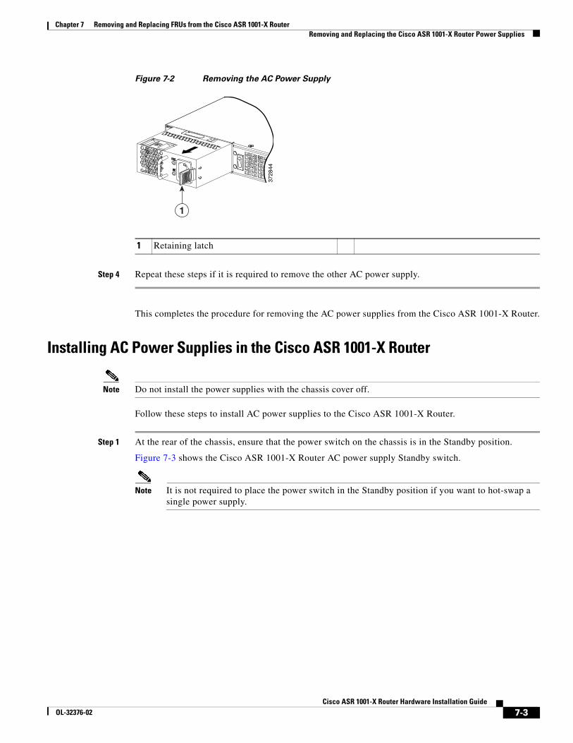
Chapter 7 Removing and Replacing FRUs from the Cisco ASR 1001-X RouterRemoving and Replacing the Cisco ASR 1001-X Router Power Supplies
Figure 7-2 Removing the AC Power Supply
Step 4 Repeat these steps if it is required to remove the other AC power supply.
This completes the procedure for removing the AC power supplies from the Cisco ASR 1001-X Router.
Installing AC Power Supplies in the Cisco ASR 1001-X Router
Note Do not install the power supplies with the chassis cover off.
Follow these steps to install AC power supplies to the Cisco ASR 1001-X Router.
Step 1 At the rear of the chassis, ensure that the power switch on the chassis is in the Standby position.
Figure 7-3 shows the Cisco ASR 1001-X Router AC power supply Standby switch.
Note It is not required to place the power switch in the Standby position if you want to hot-swap a single power supply.
3728
44
1
1 Retaining latch
7-3Cisco ASR 1001-X Router Hardware Installation Guide
OL-32376-02
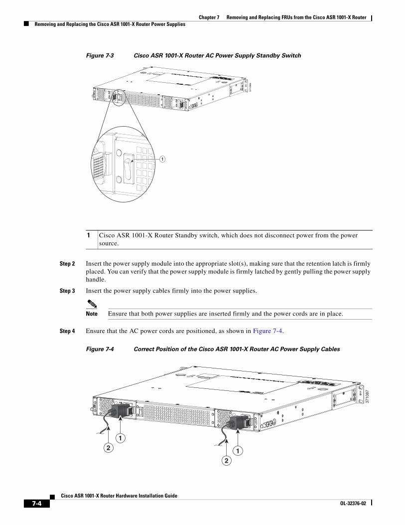
Chapter 7 Removing and Replacing FRUs from the Cisco ASR 1001-X RouterRemoving and Replacing the Cisco ASR 1001-X Router Power Supplies
Figure 7-3 Cisco ASR 1001-X Router AC Power Supply Standby Switch
Step 2 Insert the power supply module into the appropriate slot(s), making sure that the retention latch is firmly placed. You can verify that the power supply module is firmly latched by gently pulling the power supply handle.
Step 3 Insert the power supply cables firmly into the power supplies.
Note Ensure that both power supplies are inserted firmly and the power cords are in place.
Step 4 Ensure that the AC power cords are positioned, as shown in Figure 7-4.
Figure 7-4 Correct Position of the Cisco ASR 1001-X Router AC Power Supply Cables
1 Cisco ASR 1001-X Router Standby switch, which does not disconnect power from the power source.
371086
1
3710
87
12
12
7-4Cisco ASR 1001-X Router Hardware Installation Guide
OL-32376-02

Chapter 7 Removing and Replacing FRUs from the Cisco ASR 1001-X RouterRemoving and Replacing the Cisco ASR 1001-X Router Power Supplies
Step 5 If you have changed the Standby switch to the standby position in step 1, turn the Standby switch to the On position.
The power supply LEDs are illuminated (green).
This completes the procedure for connecting AC input power.
Removing DC Input Power from the Cisco ASR 1001-X Router
Note The Cisco ASR 1001-X Router has redundant power supplies that can be hot-swapped.
This section describes how to remove a DC power supply from the Cisco ASR 1001-X Router. Follow these steps:
Step 1 Turn off the circuit breaker from the power source.
Step 2 At the rear of the router, ensure that the power switch is in the Standby position.
Note It is not required to place the power switch in the Standby position if you want to hot-swap a single power supply.
Step 3 Unscrew the two terminal block wire connectors (negative and positive) on the unit. See Figure 7-7.
Step 4 Press the retaining latch towards the pull handle, grasp the handle with one hand, and pull the power supply out of the slot while supporting the weight of the power supply with the other hand. See Figure 7-5.
Figure 7-5 Removing DC Power Supply
1 AC power supply 2 Position of power supply cable
3728
45
1
1 Retaining latch
7-5Cisco ASR 1001-X Router Hardware Installation Guide
OL-32376-02
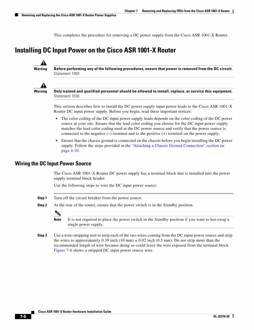
Chapter 7 Removing and Replacing FRUs from the Cisco ASR 1001-X RouterRemoving and Replacing the Cisco ASR 1001-X Router Power Supplies
This completes the procedure for removing a DC power supply from the Cisco ASR 1001-X Router.
Installing DC Input Power on the Cisco ASR 1001-X Router
Warning Before performing any of the following procedures, ensure that power is removed from the DC circuit. Statement 1003
Warning Only trained and qualified personnel should be allowed to install, replace, or service this equipment. Statement 1030
This section describes how to install the DC power supply input power leads to the Cisco ASR 1001-X Router DC input power supply. Before you begin, read these important notices:
• The color coding of the DC input power supply leads depends on the color coding of the DC power source at your site. Ensure that the lead color coding you choose for the DC input power supply matches the lead color coding used at the DC power source and verify that the power source is connected to the negative (–) terminal and to the positive (+) terminal on the power supply.
• Ensure that the chassis ground is connected on the chassis before you begin installing the DC power supply. Follow the steps provided in the “Attaching a Chassis Ground Connection” section on page 4-10.
Wiring the DC Input Power Source
The Cisco ASR 1001-X Router DC power supply has a terminal block that is installed into the power supply terminal block header.
Use the following steps to wire the DC input power source:
Step 1 Turn off the circuit breaker from the power source.
Step 2 At the rear of the router, ensure that the power switch is in the Standby position.
Note It is not required to place the power switch in the Standby position if you want to hot-swap a single power supply.
Step 3 Use a wire-stripping tool to strip each of the two wires coming from the DC input power source and strip the wires to approximately 0.39 inch (10 mm) + 0.02 inch (0.5 mm). Do not strip more than the recommended length of wire because doing so could leave the wire exposed from the terminal block. Figure 7-6 shows a stripped DC input power source wire.
7-6Cisco ASR 1001-X Router Hardware Installation Guide
OL-32376-02
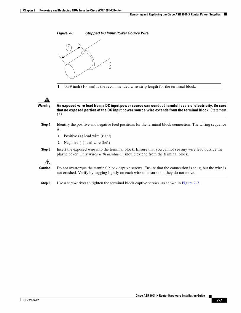
Chapter 7 Removing and Replacing FRUs from the Cisco ASR 1001-X RouterRemoving and Replacing the Cisco ASR 1001-X Router Power Supplies
Figure 7-6 Stripped DC Input Power Source Wire
Warning An exposed wire lead from a DC input power source can conduct harmful levels of electricity. Be sure that no exposed portion of the DC input power source wire extends from the terminal block. Statement 122
Step 4 Identify the positive and negative feed positions for the terminal block connection. The wiring sequence is:
1. Positive (+) lead wire (right)
2. Negative (–) lead wire (left)
Step 5 Insert the exposed wire into the terminal block. Ensure that you cannot see any wire lead outside the plastic cover. Only wires with insulation should extend from the terminal block.
Caution Do not overtorque the terminal block captive screws. Ensure that the connection is snug, but the wire is not crushed. Verify by tugging lightly on each wire to ensure that they do not move.
Step 6 Use a screwdriver to tighten the terminal block captive screws, as shown in Figure 7-7.
1 0.39 inch (10 mm) is the recommended wire-strip length for the terminal block.
57019
1
7-7Cisco ASR 1001-X Router Hardware Installation Guide
OL-32376-02
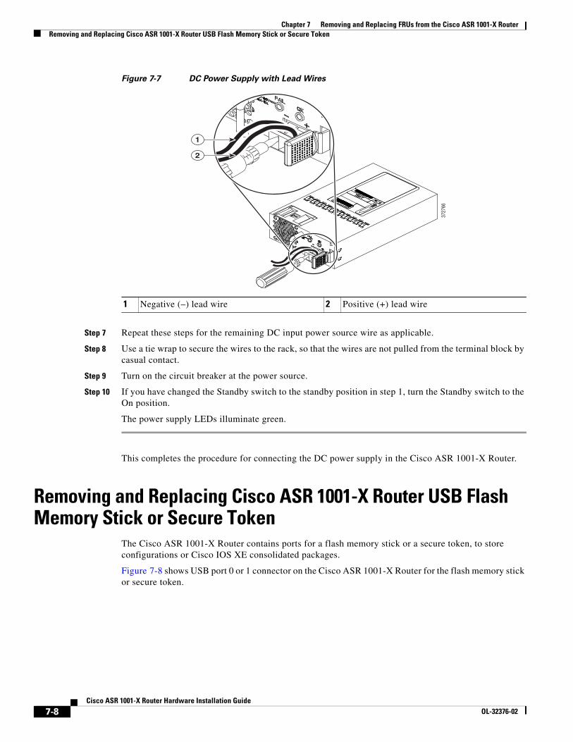
Chapter 7 Removing and Replacing FRUs from the Cisco ASR 1001-X RouterRemoving and Replacing Cisco ASR 1001-X Router USB Flash Memory Stick or Secure Token
Figure 7-7 DC Power Supply with Lead Wires
Step 7 Repeat these steps for the remaining DC input power source wire as applicable.
Step 8 Use a tie wrap to secure the wires to the rack, so that the wires are not pulled from the terminal block by casual contact.
Step 9 Turn on the circuit breaker at the power source.
Step 10 If you have changed the Standby switch to the standby position in step 1, turn the Standby switch to the On position.
The power supply LEDs illuminate green.
This completes the procedure for connecting the DC power supply in the Cisco ASR 1001-X Router.
Removing and Replacing Cisco ASR 1001-X Router USB Flash Memory Stick or Secure Token
The Cisco ASR 1001-X Router contains ports for a flash memory stick or a secure token, to store configurations or Cisco IOS XE consolidated packages.
Figure 7-8 shows USB port 0 or 1 connector on the Cisco ASR 1001-X Router for the flash memory stick or secure token.
1 Negative (–) lead wire 2 Positive (+) lead wire
3727
66
1
2
7-8Cisco ASR 1001-X Router Hardware Installation Guide
OL-32376-02
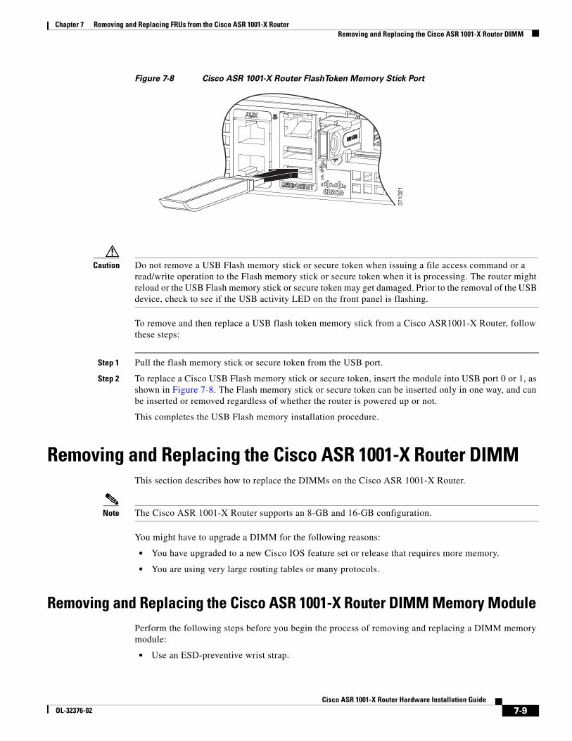
Chapter 7 Removing and Replacing FRUs from the Cisco ASR 1001-X RouterRemoving and Replacing the Cisco ASR 1001-X Router DIMM
Figure 7-8 Cisco ASR 1001-X Router FlashToken Memory Stick Port
Caution Do not remove a USB Flash memory stick or secure token when issuing a file access command or a read/write operation to the Flash memory stick or secure token when it is processing. The router might reload or the USB Flash memory stick or secure token may get damaged. Prior to the removal of the USB device, check to see if the USB activity LED on the front panel is flashing.
To remove and then replace a USB flash token memory stick from a Cisco ASR1001-X Router, follow these steps:
Step 1 Pull the flash memory stick or secure token from the USB port.
Step 2 To replace a Cisco USB Flash memory stick or secure token, insert the module into USB port 0 or 1, as shown in Figure 7-8. The Flash memory stick or secure token can be inserted only in one way, and can be inserted or removed regardless of whether the router is powered up or not.
This completes the USB Flash memory installation procedure.
Removing and Replacing the Cisco ASR 1001-X Router DIMMThis section describes how to replace the DIMMs on the Cisco ASR 1001-X Router.
Note The Cisco ASR 1001-X Router supports an 8-GB and 16-GB configuration.
You might have to upgrade a DIMM for the following reasons:
• You have upgraded to a new Cisco IOS feature set or release that requires more memory.
• You are using very large routing tables or many protocols.
Removing and Replacing the Cisco ASR 1001-X Router DIMM Memory ModulePerform the following steps before you begin the process of removing and replacing a DIMM memory module:
• Use an ESD-preventive wrist strap.
3713
21
7-9Cisco ASR 1001-X Router Hardware Installation Guide
OL-32376-02
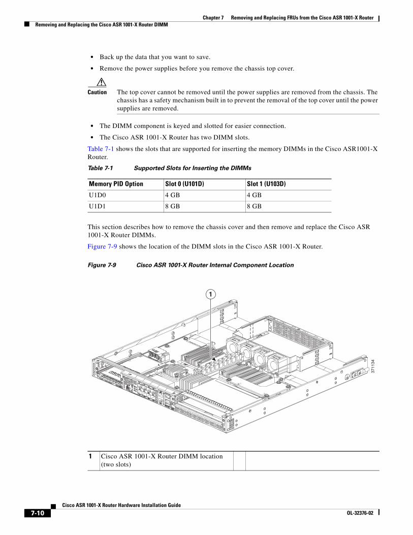
Chapter 7 Removing and Replacing FRUs from the Cisco ASR 1001-X RouterRemoving and Replacing the Cisco ASR 1001-X Router DIMM
• Back up the data that you want to save.
• Remove the power supplies before you remove the chassis top cover.
Caution The top cover cannot be removed until the power supplies are removed from the chassis. The chassis has a safety mechanism built in to prevent the removal of the top cover until the power supplies are removed.
• The DIMM component is keyed and slotted for easier connection.
• The Cisco ASR 1001-X Router has two DIMM slots.
Table 7-1 shows the slots that are supported for inserting the memory DIMMs in the Cisco ASR1001-X Router.
This section describes how to remove the chassis cover and then remove and replace the Cisco ASR 1001-X Router DIMMs.
Figure 7-9 shows the location of the DIMM slots in the Cisco ASR 1001-X Router.
Figure 7-9 Cisco ASR 1001-X Router Internal Component Location
Table 7-1 Supported Slots for Inserting the DIMMs
Memory PID Option Slot 0 (U101D) Slot 1 (U103D)
U1D0 4 GB 4 GB
U1D1 8 GB 8 GB
1 Cisco ASR 1001-X Router DIMM location (two slots)
1
3711
34
7-10Cisco ASR 1001-X Router Hardware Installation Guide
OL-32376-02
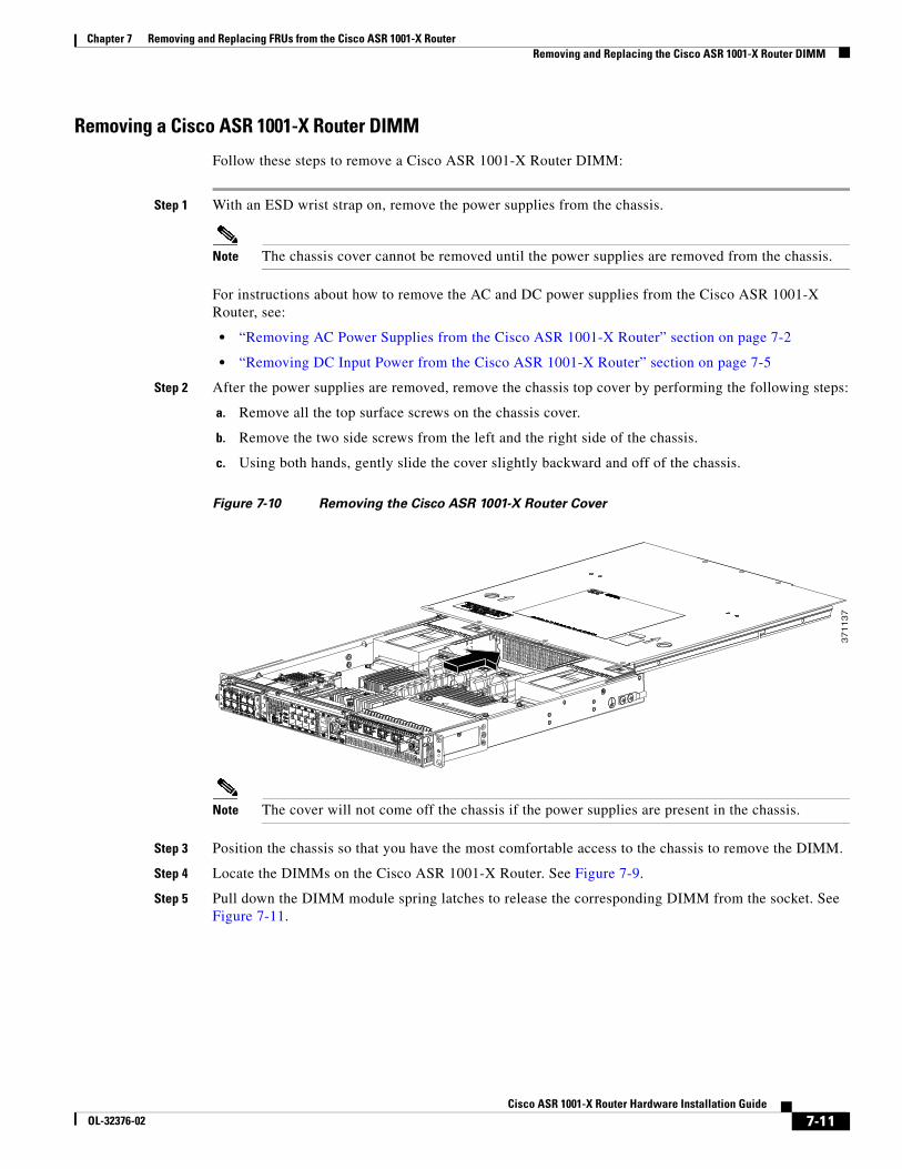
Chapter 7 Removing and Replacing FRUs from the Cisco ASR 1001-X RouterRemoving and Replacing the Cisco ASR 1001-X Router DIMM
Removing a Cisco ASR 1001-X Router DIMM
Follow these steps to remove a Cisco ASR 1001-X Router DIMM:
Step 1 With an ESD wrist strap on, remove the power supplies from the chassis.
Note The chassis cover cannot be removed until the power supplies are removed from the chassis.
For instructions about how to remove the AC and DC power supplies from the Cisco ASR 1001-X Router, see:
• “Removing AC Power Supplies from the Cisco ASR 1001-X Router” section on page 7-2
• “Removing DC Input Power from the Cisco ASR 1001-X Router” section on page 7-5
Step 2 After the power supplies are removed, remove the chassis top cover by performing the following steps:
a. Remove all the top surface screws on the chassis cover.
b. Remove the two side screws from the left and the right side of the chassis.
c. Using both hands, gently slide the cover slightly backward and off of the chassis.
Figure 7-10 Removing the Cisco ASR 1001-X Router Cover
Note The cover will not come off the chassis if the power supplies are present in the chassis.
Step 3 Position the chassis so that you have the most comfortable access to the chassis to remove the DIMM.
Step 4 Locate the DIMMs on the Cisco ASR 1001-X Router. See Figure 7-9.
Step 5 Pull down the DIMM module spring latches to release the corresponding DIMM from the socket. See Figure 7-11.
37
11
37
7-11Cisco ASR 1001-X Router Hardware Installation Guide
OL-32376-02
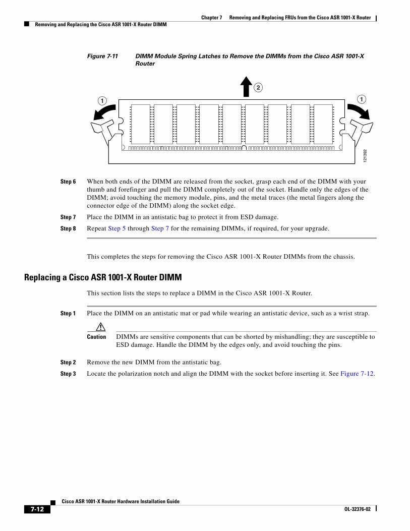
Chapter 7 Removing and Replacing FRUs from the Cisco ASR 1001-X RouterRemoving and Replacing the Cisco ASR 1001-X Router DIMM
Figure 7-11 DIMM Module Spring Latches to Remove the DIMMs from the Cisco ASR 1001-X
Router
Step 6 When both ends of the DIMM are released from the socket, grasp each end of the DIMM with your thumb and forefinger and pull the DIMM completely out of the socket. Handle only the edges of the DIMM; avoid touching the memory module, pins, and the metal traces (the metal fingers along the connector edge of the DIMM) along the socket edge.
Step 7 Place the DIMM in an antistatic bag to protect it from ESD damage.
Step 8 Repeat Step 5 through Step 7 for the remaining DIMMs, if required, for your upgrade.
This completes the steps for removing the Cisco ASR 1001-X Router DIMMs from the chassis.
Replacing a Cisco ASR 1001-X Router DIMM
This section lists the steps to replace a DIMM in the Cisco ASR 1001-X Router.
Step 1 Place the DIMM on an antistatic mat or pad while wearing an antistatic device, such as a wrist strap.
Caution DIMMs are sensitive components that can be shorted by mishandling; they are susceptible to ESD damage. Handle the DIMM by the edges only, and avoid touching the pins.
Step 2 Remove the new DIMM from the antistatic bag.
Step 3 Locate the polarization notch and align the DIMM with the socket before inserting it. See Figure 7-12.
1213
92
1 1
2
7-12Cisco ASR 1001-X Router Hardware Installation Guide
OL-32376-02
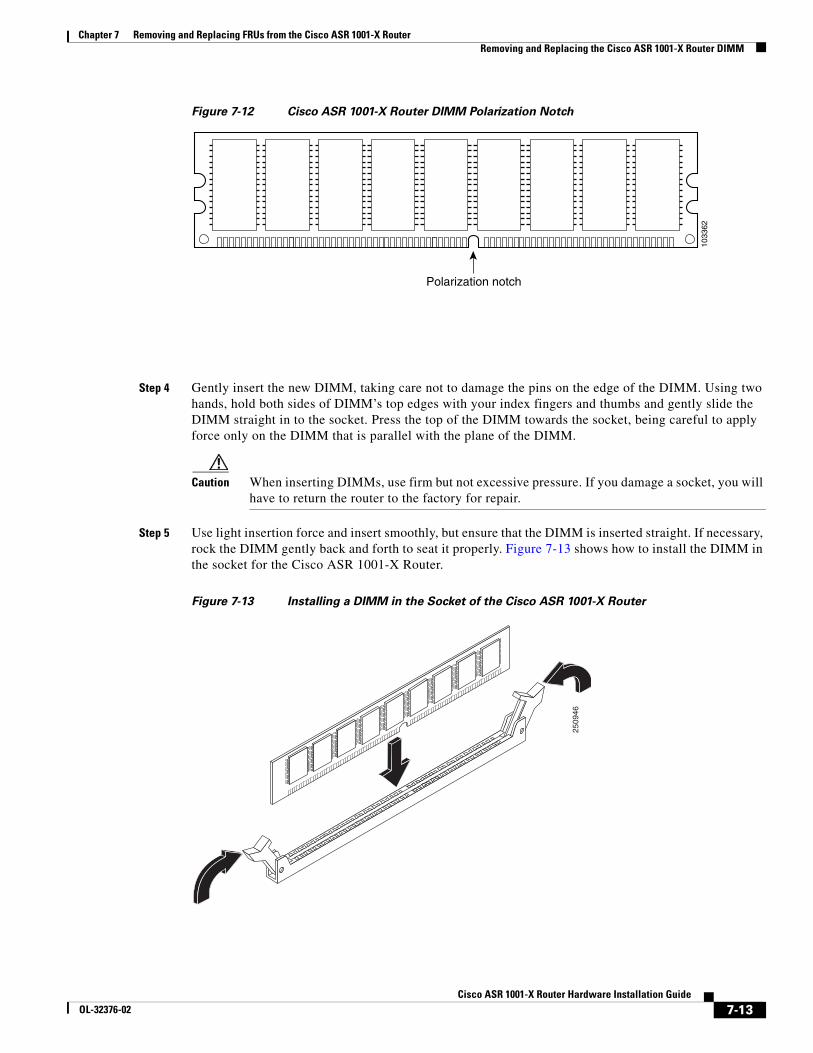
Chapter 7 Removing and Replacing FRUs from the Cisco ASR 1001-X RouterRemoving and Replacing the Cisco ASR 1001-X Router DIMM
Figure 7-12 Cisco ASR 1001-X Router DIMM Polarization Notch
Step 4 Gently insert the new DIMM, taking care not to damage the pins on the edge of the DIMM. Using two hands, hold both sides of DIMM’s top edges with your index fingers and thumbs and gently slide the DIMM straight in to the socket. Press the top of the DIMM towards the socket, being careful to apply force only on the DIMM that is parallel with the plane of the DIMM.
Caution When inserting DIMMs, use firm but not excessive pressure. If you damage a socket, you will have to return the router to the factory for repair.
Step 5 Use light insertion force and insert smoothly, but ensure that the DIMM is inserted straight. If necessary, rock the DIMM gently back and forth to seat it properly. Figure 7-13 shows how to install the DIMM in the socket for the Cisco ASR 1001-X Router.
Figure 7-13 Installing a DIMM in the Socket of the Cisco ASR 1001-X Router
Polarization notch
1033
62
2509
46
7-13Cisco ASR 1001-X Router Hardware Installation Guide
OL-32376-02

Chapter 7 Removing and Replacing FRUs from the Cisco ASR 1001-X RouterRemoving and Replacing a Cisco ASR 1001-X Router SPA
Step 6 After the DIMM is installed, check whether the release levers are flush against the sides of the DIMM socket. If they are not, the DIMM might not be seated properly. If the DIMM appears misaligned, carefully remove it according to the removal procedure and then reseat it in the socket. Push the DIMM firmly back into the socket until the release levers are flush against the sides of the DIMM socket.
Step 7 Repeat Step 4 through Step 6 for the remaining DIMM.
Step 8 Replace the Cisco ASR 1001-X Router top cover:
a. Slide the cover onto the chassis ensuring that the interlock hook feature fits on the chassis cover and base.
b. Install the top surface screws and the side screws and tighten them slightly.
Step 9 Install the power supplies into the chassis. See:
• Installing AC Power Supplies in the Cisco ASR 1001-X Router, page 7-3
• Installing DC Input Power on the Cisco ASR 1001-X Router, page 7-6
This completes the procedure for replacing the Cisco ASR 1001-X Router DIMM.
After you have correctly installed the Cisco ASR 1001-X Router DIMMs, the system should reboot properly.
If the system fails to reboot properly or if the console terminal displays a checksum or memory error after you have installed the new DIMMs, check the following:
Ensure that both the DIMMs are installed correctly. If necessary, shut down the system and remove the chassis cover. Check the DIMMs by looking straight down on them to inspect them at eye level. The DIMMs should be aligned at the same angle and the same height when properly installed. If a DIMM appears to stick out or rest in the socket at a different angle from the other, remove the DIMM and reinsert it. Replace the top chassis cover, and reboot the system for another installation check.
Note After several attempts, if the system fails to restart properly, contact a Cisco service representative for assistance. Before you call, make note of any error messages, unusual LED states, or other indications that might help solve the problem.
Removing and Replacing a Cisco ASR 1001-X Router SPA The online insertion and removal (OIR) feature allows you to install and replace shared port adapters (SPAs) while the router is operating, you do not have to shut down the system’s power, although you should not run traffic through the shared port adapter while it is being removed. OIR is a method that is seamless to end users on the network, maintains all routing information, and preserves sessions.
Note As you disengage the SPA from the router, OIR shuts down all the active interfaces in the SPA.
Note For detailed information about SPA software commands, such as preparing for OIR of SPAs, and activating and deactivating configuration examples, see the Cisco ASR 1000 Series Aggregation Services Routers SIP and SPA Hardware Installation Guide.
We suggest you have the following tools and parts readily available for installing a SPA:
7-14Cisco ASR 1001-X Router Hardware Installation Guide
OL-32376-02
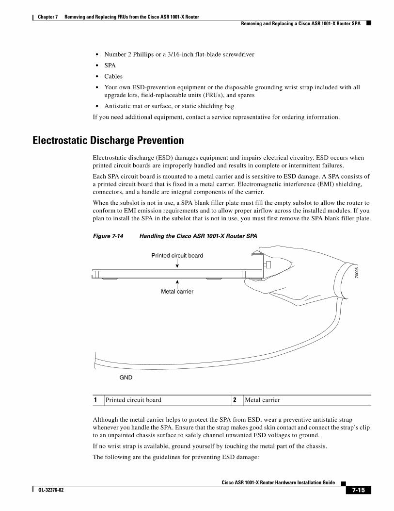
Chapter 7 Removing and Replacing FRUs from the Cisco ASR 1001-X RouterRemoving and Replacing a Cisco ASR 1001-X Router SPA
• Number 2 Phillips or a 3/16-inch flat-blade screwdriver
• SPA
• Cables
• Your own ESD-prevention equipment or the disposable grounding wrist strap included with all upgrade kits, field-replaceable units (FRUs), and spares
• Antistatic mat or surface, or static shielding bag
If you need additional equipment, contact a service representative for ordering information.
Electrostatic Discharge PreventionElectrostatic discharge (ESD) damages equipment and impairs electrical circuitry. ESD occurs when printed circuit boards are improperly handled and results in complete or intermittent failures.
Each SPA circuit board is mounted to a metal carrier and is sensitive to ESD damage. A SPA consists of a printed circuit board that is fixed in a metal carrier. Electromagnetic interference (EMI) shielding, connectors, and a handle are integral components of the carrier.
When the subslot is not in use, a SPA blank filler plate must fill the empty subslot to allow the router to conform to EMI emission requirements and to allow proper airflow across the installed modules. If you plan to install the SPA in the subslot that is not in use, you must first remove the SPA blank filler plate.
Figure 7-14 Handling the Cisco ASR 1001-X Router SPA
Although the metal carrier helps to protect the SPA from ESD, wear a preventive antistatic strap whenever you handle the SPA. Ensure that the strap makes good skin contact and connect the strap’s clip to an unpainted chassis surface to safely channel unwanted ESD voltages to ground.
If no wrist strap is available, ground yourself by touching the metal part of the chassis.
The following are the guidelines for preventing ESD damage:
1 Printed circuit board 2 Metal carrier
7000
6
Metal carrier
GND
Printed circuit board
7-15Cisco ASR 1001-X Router Hardware Installation Guide
OL-32376-02

Chapter 7 Removing and Replacing FRUs from the Cisco ASR 1001-X RouterRemoving and Replacing a Cisco ASR 1001-X Router SPA
• Always use an ESD wrist strap or ankle strap when installing or replacing a Cisco ASR 1001-X SPA. Ensure that the ESD strap makes contact with your skin.
• Handle the Cisco ASR 1001-X SPA by its metal carrier edges and handles; avoid touching the printed circuit board or any connector pins.
• When removing the Cisco ASR 1001-X SPA, place it on an antistatic surface with the printed circuit board components facing upward, or in a static shielding bag.
Removing a Shared Port AdapterTo remove a SPA, follow these steps.
Step 1 Attach an ESD wrist strap between you and an unpainted chassis surface.
Step 2 Stop the SPA so that there is no traffic running through the SPA when it is removed.
Caution Removing a SPA while traffic is flowing through the ports may cause system disruption.
Refer to the following example to stop the SPA in the SPA bay 0/1:
a. At the router# prompt, enter hw-module subslot 0/1 stop and press Enter.
b. At the router# prompt, enter end and press Enter.
Step 3 Disconnect all the cables from the SPA.
Step 4 Unscrew the captive installation screws on either side of the SPA.
Step 5 Grasp the handles with both hands and pull the SPA.
You have completed the Cisco ASR 1001-X Router SPA removal procedure.
Replacing a Shared Port AdapterTo replace a SPA, follow these steps:
Step 1 To insert a SPA, locate the guide rails that hold the SPA in place. They are at the top left and top right of the SPA slot and are recessed about an inch.
Step 2 Carefully slide the SPA all the way in using both hands until the SPA is firmly seated in the SPA interface connector. When fully seated, the SPA might be slightly behind the faceplate.
Step 3 After the SPA is properly seated, fasten the SPA in place with the captive installation screws on either side of the SPA.
Note Ensure that you fasten the captive installation screws to provide appropriate connectivity.
Step 4 Restart the SPA using the following steps:
a. At the router# prompt, enter hw-module subslot 0/1 start and press Enter.
b. At the router# prompt, enter end and press Enter.
7-16Cisco ASR 1001-X Router Hardware Installation Guide
OL-32376-02
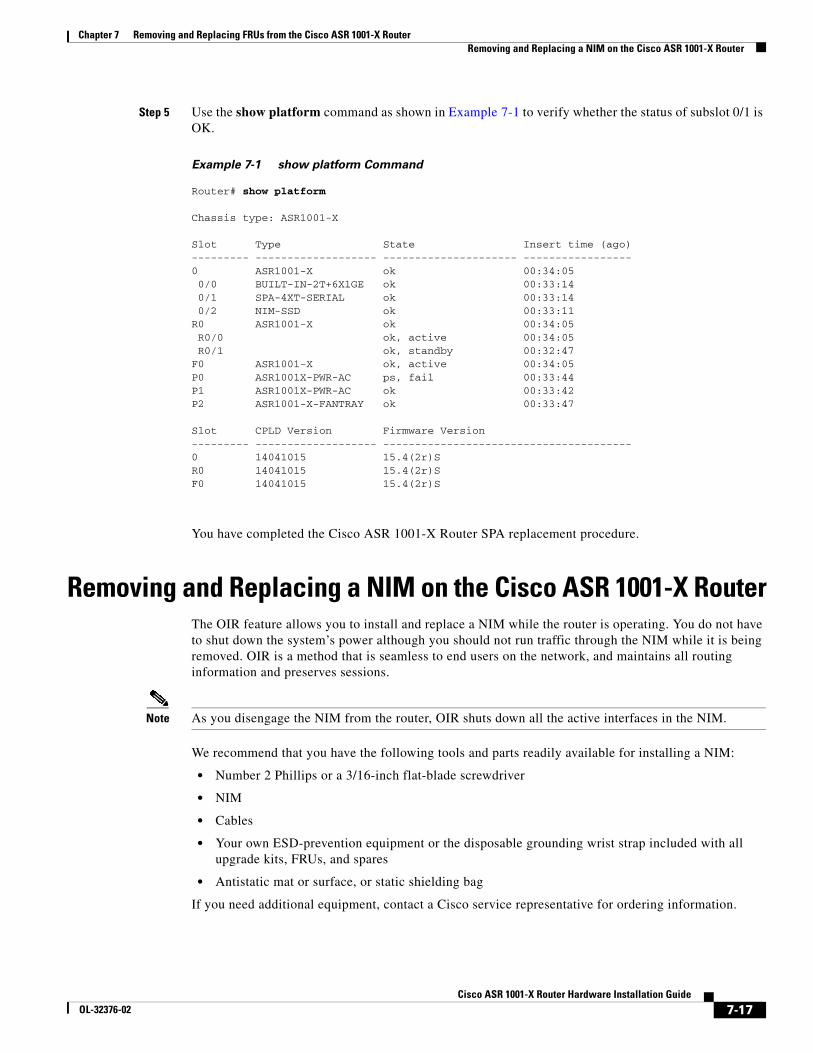
Chapter 7 Removing and Replacing FRUs from the Cisco ASR 1001-X RouterRemoving and Replacing a NIM on the Cisco ASR 1001-X Router
Step 5 Use the show platform command as shown in Example 7-1 to verify whether the status of subslot 0/1 is OK.
Example 7-1 show platform Command
Router# show platform
Chassis type: ASR1001-X
Slot Type State Insert time (ago) --------- ------------------- --------------------- ----------------- 0 ASR1001-X ok 00:34:05 0/0 BUILT-IN-2T+6X1GE ok 00:33:14 0/1 SPA-4XT-SERIAL ok 00:33:14 0/2 NIM-SSD ok 00:33:11 R0 ASR1001-X ok 00:34:05 R0/0 ok, active 00:34:05 R0/1 ok, standby 00:32:47 F0 ASR1001-X ok, active 00:34:05 P0 ASR1001X-PWR-AC ps, fail 00:33:44 P1 ASR1001X-PWR-AC ok 00:33:42 P2 ASR1001-X-FANTRAY ok 00:33:47
Slot CPLD Version Firmware Version --------- ------------------- --------------------------------------- 0 14041015 15.4(2r)S R0 14041015 15.4(2r)S F0 14041015 15.4(2r)S
You have completed the Cisco ASR 1001-X Router SPA replacement procedure.
Removing and Replacing a NIM on the Cisco ASR 1001-X RouterThe OIR feature allows you to install and replace a NIM while the router is operating. You do not have to shut down the system’s power although you should not run traffic through the NIM while it is being removed. OIR is a method that is seamless to end users on the network, and maintains all routing information and preserves sessions.
Note As you disengage the NIM from the router, OIR shuts down all the active interfaces in the NIM.
We recommend that you have the following tools and parts readily available for installing a NIM:
• Number 2 Phillips or a 3/16-inch flat-blade screwdriver
• NIM
• Cables
• Your own ESD-prevention equipment or the disposable grounding wrist strap included with all upgrade kits, FRUs, and spares
• Antistatic mat or surface, or static shielding bag
If you need additional equipment, contact a Cisco service representative for ordering information.
7-17Cisco ASR 1001-X Router Hardware Installation Guide
OL-32376-02
Chapter 7 Removing and Replacing FRUs from the Cisco ASR 1001-X RouterRemoving and Replacing a NIM on the Cisco ASR 1001-X Router
Note For information about electrostatic discharge prevention, see the “Electrostatic Discharge Prevention” section on page 7-15.
Removing a NIMTo remove a NIM, follow these steps.
Step 1 Attach an ESD wrist strap between you and an unpainted chassis surface.
Step 2 Stop the NIM so that there is no traffic running through the NIM when it is removed, using the following steps:
Caution Removing a NIM while traffic is flowing through the ports may cause system disruption.
a. At the router# prompt, enter hw-module subslot 0/2 stop and press Enter.
b. At the router# prompt, enter end and press Enter.
Step 3 Disconnect all the cables from the NIM.
Step 4 Unscrew the captive installation screws on either side of the NIM.
Step 5 Grasp the handles using both hands and pull out the NIM.
You have completed the NIM removal procedure.
Replacing a NIMTo replace a NIM, follow these steps:
Step 1 To insert a NIM, locate the guide rails that hold the NIM in place. They are at the top left and top right of the NIM slot and are recessed about an inch.
Step 2 Carefully slide the NIM all the way in using both hands until the NIM is firmly seated in the NIM interface connector. When fully seated, the NIM might be slightly behind the faceplate.
Step 3 After the NIM is properly seated, fasten the NIM in place with the captive installation screws on either side of the NIM.
Note Ensure that you screw down the captive installation screws to provide appropriate connectivity.
The NIM should power up after installation.
Step 4 Use the show platform command as shown in Example 7-1 to verify whether the status of subslot 0/2 is OK.
You have completed the NIM replacement procedure.
7-18Cisco ASR 1001-X Router Hardware Installation Guide
OL-32376-02
Chapter 7 Removing and Replacing FRUs from the Cisco ASR 1001-X RouterRemoving and Replacing an SSD from the NIM-SSD Module
Removing and Replacing an SSD from the NIM-SSD ModuleThis section explains how to remove a solid state drive (SSD) from the NIM-SSD module.
Caution The Cisco 4400 Series Integrated Services Routers (ISR) that support NIM-SSD and the Cisco ASR 1000 Series Aggregated Services Routers that support NIM-SSD do not utilize the NIM in the same format.
Caution The NIM-SSD module of the Cisco ASR 1001-X Router recognizes both hard drives as one partition. For example, two 200 GB hard drives are treated as one 400 GB hard drive. Since there is no data backup capability in the NIM-SSD module, replacing any SSD will cause complete data loss. Ensure that you clean up and back up all important data before replacing any SSD.
Restrictions
• The Cisco ASR 1001-X Router does not support dynamic removal and shutdown of SSD drives while the NIM-SSD module is still powered on. Such ungraceful actions may cause disk corruption and you will see kernel messages indicating that the module did not shutdown gracefully. Power down the NIM-SSD module and wait for the power LED to turn off before removing and replacing the SSD.
• Cisco SSD Carrier Card NIM without SSD drives is not supported.
Removing an SSD from the NIM-SSD ModuleTo remove an SSD from the NIM-SSD module, follow these steps:
Step 1 Access the NIM-SSD slot.
Step 2 Stop the SSD module using the following steps:
a. At the router# prompt, enter hw-module subslot 0/2 stop and press Enter.
b. At the router# prompt, enter end and press Enter.
Step 3 Unscrew the captive installation screws on either side of the NIM-SSD to remove the front faceplate of the NIM, as shown in Figure 7-15.
7-19Cisco ASR 1001-X Router Hardware Installation Guide
OL-32376-02
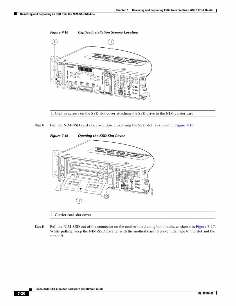
Chapter 7 Removing and Replacing FRUs from the Cisco ASR 1001-X RouterRemoving and Replacing an SSD from the NIM-SSD Module
Figure 7-15 Captive Installation Screws Location
Step 4 Pull the NIM-SSD card slot cover down, exposing the SSD slot, as shown in Figure 7-16.
Figure 7-16 Opening the SSD Slot Cover
Step 5 Pull the NIM-SSD out of the connector on the motherboard using both hands, as shown in Figure 7-17. While pulling, keep the NIM-SSD parallel with the motherboard to prevent damage to the slot and the standoff.
11
3729
32
1. Captive screws on the SSD slot cover attaching the SSD drive to the NIM carrier card
1
3729
33
1. Carrier card slot cover
7-20Cisco ASR 1001-X Router Hardware Installation Guide
OL-32376-02
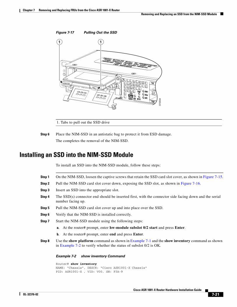
Chapter 7 Removing and Replacing FRUs from the Cisco ASR 1001-X RouterRemoving and Replacing an SSD from the NIM-SSD Module
Figure 7-17 Pulling Out the SSD
Step 6 Place the NIM-SSD in an antistatic bag to protect it from ESD damage.
The completes the removal of the NIM-SSD.
Installing an SSD into the NIM-SSD ModuleTo install an SSD into the NIM-SSD module, follow these steps:
Step 1 On the NIM-SSD, loosen the captive screws that retain the SSD card slot cover, as shown in Figure 7-15.
Step 2 Pull the NIM-SSD card slot cover down, exposing the SSD slot, as shown in Figure 7-16.
Step 3 Insert an SSD into the appropriate slot.
Step 4 The SSD(s) connector end should be inserted first, with the connector side facing down and the serial number facing up.
Step 5 Pull the NIM-SSD card slot cover up and into place over the SSD.
Step 6 Verify that the NIM-SSD is installed correctly.
Step 7 Start the NIM-SSD module using the following steps:
a. At the router# prompt, enter hw-module subslot 0/2 start and press Enter.
b. At the router# prompt, enter end and press Enter.
Step 8 Use the show platform command as shown in Example 7-1 and the show inventory command as shown in Example 7-2 to verify whether the status of subslot 0/2 is OK.
Example 7-2 show inventory Command
Router# show inventoryNAME: "Chassis", DESCR: "Cisco ASR1001-X Chassis"PID: ASR1001-X , VID: V00, SN: P3A-9
3729
34
11
1. Tabs to pull out the SSD drive
7-21Cisco ASR 1001-X Router Hardware Installation Guide
OL-32376-02
Chapter 7 Removing and Replacing FRUs from the Cisco ASR 1001-X RouterRepacking the Router
NAME: "Power Supply Module 0", DESCR: "Cisco ASR1001-X AC Power Supply"PID: ASR1001X-PWR-AC , VID: V00, SN: LIT171616HJ
NAME: "Power Supply Module 1", DESCR: "Cisco ASR1001-X AC Power Supply"PID: ASR1001X-PWR-AC , VID: V00, SN: LIT171616GG
NAME: "Fan Tray 0", DESCR: "Cisco ASR1001-X Fan Tray"PID: ASR1001-X-FANTRAY , VID: , SN:
NAME: "module 0", DESCR: "Cisco ASR1001-X SPA Interface Processor"PID: ASR1001-X , VID: , SN:
NAME: "SPA subslot 0/1", DESCR: "4-port Serial Shared Port Adapter"PID: SPA-4XT-SERIAL , VID: V01, SN: JAB111105M4
NAME: "NIM subslot 0/2", DESCR: "NIM SSD Module"PID: NIM-SSD , VID: V01, SN: FOC18071SNN
NAME: "subslot 0/2 disk0", DESCR: "harddisk"PID: Micron P400m-MTFDDAK400MAN , VID: 0225 , SN: MSA1802019A
NAME: "subslot 0/2 disk1", DESCR: "harddisk"PID: UB88RTB400HE6-NTH-EID , VID: 5.2.4 , SN: 11000302418
NAME: "SPA subslot 0/0", DESCR: "8-port Built-in GE SPA"PID: BUILT-IN-2T+6X1GE , VID: , SN:
NAME: "module R0", DESCR: "Cisco ASR1001-X Route Processor"PID: ASR1001-X , VID: V00, SN: JAE1719030S
NAME: "module F0", DESCR: "Cisco ASR1001-X Embedded Services Processor"PID: ASR1001-X , VID: , SN:
Router#
Step 9 Use the dir hardisk: command to verify whether the total file size of the hard disk partitions are correct. For example:
Router# dir harddisk:
Directory of harddisk:
11 drwx 16384 Jul 16 2014 11:30:24 -03:00 lost+found
787616940032 bytes total (747608293376 bytes free)
Router#
You have completed the NIM-SSD replacement procedure.
Repacking the RouterIf your system is damaged, you must repack it for return shipment.
Before you return the router or move the router to a different location, repack the system using the original packaging material.
7-22Cisco ASR 1001-X Router Hardware Installation Guide
OL-32376-02
CisOL-32376-02
C H A P T E R 8
Upgrading the ROMMON and CPLDThis chapter describes the procedures to upgrade the ROMMON on the Cisco ASR 1001-X Router.
This chapter contains the following sections:
• Upgrading the ROMMON, page 8-1
• Compatible ROMMON Releases, page 8-5
• Resolved Caveats, page 8-6
• Hardware the Require a CPLD Upgrade, page 8-6
• Checking Hardware and Software Compatibility, page 8-7
Upgrading the ROMMONThe ROMMON must be upgraded on the Cisco ASR 1001-X Router if the system message on the router indicates that the ROMMON requires an upgrade, or when a Cisco technical support representative suggests a ROMMON upgrade.
Compatibility Requirements
Note For information about the compatibility between the ROMMON releases and the Cisco ASR 1001-X Router, see the “ROMMON Release Requirements” section in the Cisco ASR 1000 Series Aggregation Services Routers Release Notes.
To upgrade the ROMMON image, you must have access to the privileged EXEC mode prompt or the diagnostic mode prompt on the router.
Checking the Current ROMMON VersionIf you are unsure whether a ROMMON upgrade is required, follow the instructions provided in this section.
Run the show rom-monitor command or the show platform command to display the version of ROMMON running on your router. If the output shows that the release to which you plan to upgrade is already installed, you need not upgrade the ROMMON.
8-1co ASR 1001-X Router Hardware Installation Guide
Chapter 8 Upgrading the ROMMON and CPLDUpgrading the ROMMON
For a single form-factor platform such as the Cisco ASR 1001-X Router, all of the following commands display the same output:
• show rom-monitor 0
• show rom-monitor F0
• show rom-monitor FP
• show rom-monitor R0
• show rom-monitor RP
In the following example, the output of the show rom-monitor command indicates that an upgrade to Release 15.4(2r)S is not required:
Router# show rom-monitor 0
System Bootstrap, Version 15.4(2r)S, RELEASE SOFTWARE (fc1)Copyright (c) 1994-2014 by cisco Systems, Inc.
Upgrading the ROMMON for the Cisco ASR 1001-X RouterUse this procedure to upgrade the ROMMON for the Cisco ASR 1001-X Router:
Step 1 (Optional) Run the show platform command or the show rom-monitor slot command to see the current release number of ROMMON on the hardware.
Step 2 If the ROMMON image has not been copied onto the router, copy the PKG file that is made available as part of this ROMMON release onto the bootflash: or usb[0-1]: file system using the copy source-location destination-location command. For example, if you are upgrading to Release 15.4(2r)S, copy the asr1000-rommon.154-2r.S.pkg file.
Step 3 Run the dir file-system command to verify that the ROMMON file is copied into the specified directory.
Step 4 Run the upgrade rom-monitor filename location all command to begin the ROMMON image upgrade, where location is the path to the ROMMON file.
Caution Do not remove hardware, turn off power, or interrupt the router in any way during the ROMMON upgrade. Although the router should be able to recover from most interruptions during the ROMMON upgrade, certain scenarios may cause unpredictable problems.
Step 5 Messages pertaining to the upgrade are displayed on the console. After the display of these messages stops and the router prompt is available, run the reload command to reload the router.
Note If you change the configuration register setting through Cisco IOS after initiating a ROMMON upgrade, but before reloading the router, the configuration register setting will not be applied. Reload the router and allow the ROMMON upgrade to be applied prior to changing the configuration register in Cisco IOS.
Step 6 If autoboot has not been enabled by using the config-register 0x2102 command, run the boot filesystem:/file-location command at the ROMMON prompt to boot the Cisco IOS XE image, where filesystem:/file-location is the path to the consolidated package file. The ROMMON upgrade is not permanent for any piece of hardware until the Cisco IOS XE image is booted.
8-2Cisco ASR 1001-X Router Hardware Installation Guide
OL-32376-02
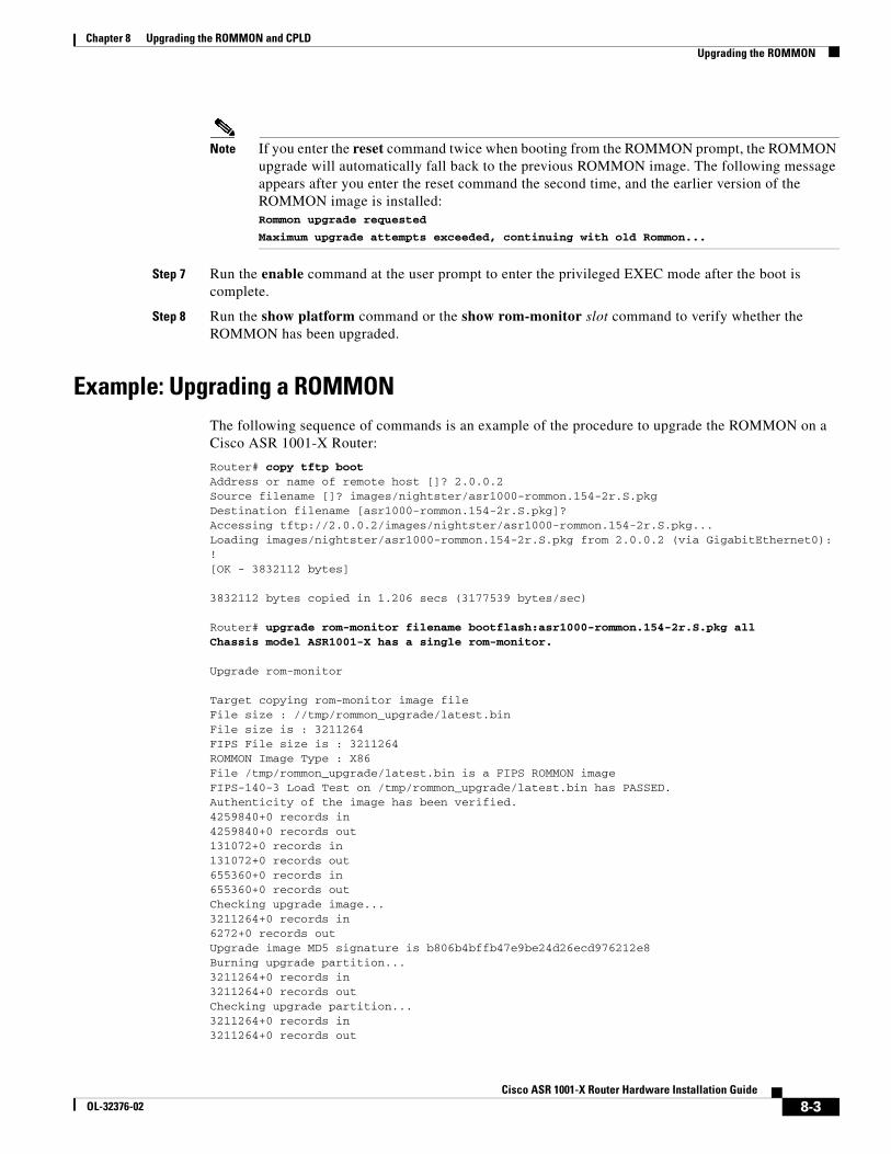
Chapter 8 Upgrading the ROMMON and CPLDUpgrading the ROMMON
Note If you enter the reset command twice when booting from the ROMMON prompt, the ROMMON upgrade will automatically fall back to the previous ROMMON image. The following message appears after you enter the reset command the second time, and the earlier version of the ROMMON image is installed: Rommon upgrade requested
Maximum upgrade attempts exceeded, continuing with old Rommon...
Step 7 Run the enable command at the user prompt to enter the privileged EXEC mode after the boot is complete.
Step 8 Run the show platform command or the show rom-monitor slot command to verify whether the ROMMON has been upgraded.
Example: Upgrading a ROMMONThe following sequence of commands is an example of the procedure to upgrade the ROMMON on a Cisco ASR 1001-X Router:
Router# copy tftp bootAddress or name of remote host []? 2.0.0.2Source filename []? images/nightster/asr1000-rommon.154-2r.S.pkgDestination filename [asr1000-rommon.154-2r.S.pkg]?Accessing tftp://2.0.0.2/images/nightster/asr1000-rommon.154-2r.S.pkg...Loading images/nightster/asr1000-rommon.154-2r.S.pkg from 2.0.0.2 (via GigabitEthernet0): ![OK - 3832112 bytes]
3832112 bytes copied in 1.206 secs (3177539 bytes/sec)
Router# upgrade rom-monitor filename bootflash:asr1000-rommon.154-2r.S.pkg allChassis model ASR1001-X has a single rom-monitor.
Upgrade rom-monitor
Target copying rom-monitor image fileFile size : //tmp/rommon_upgrade/latest.binFile size is : 3211264FIPS File size is : 3211264ROMMON Image Type : X86File /tmp/rommon_upgrade/latest.bin is a FIPS ROMMON imageFIPS-140-3 Load Test on /tmp/rommon_upgrade/latest.bin has PASSED.Authenticity of the image has been verified.4259840+0 records in4259840+0 records out131072+0 records in131072+0 records out655360+0 records in655360+0 records outChecking upgrade image...3211264+0 records in6272+0 records outUpgrade image MD5 signature is b806b4bffb47e9be24d26ecd976212e8Burning upgrade partition...3211264+0 records in3211264+0 records outChecking upgrade partition...3211264+0 records in3211264+0 records out
8-3Cisco ASR 1001-X Router Hardware Installation Guide
OL-32376-02
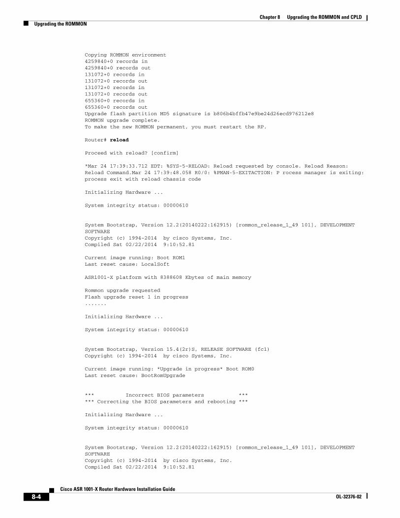
Chapter 8 Upgrading the ROMMON and CPLDUpgrading the ROMMON
Copying ROMMON environment4259840+0 records in4259840+0 records out131072+0 records in131072+0 records out131072+0 records in131072+0 records out655360+0 records in655360+0 records outUpgrade flash partition MD5 signature is b806b4bffb47e9be24d26ecd976212e8ROMMON upgrade complete.To make the new ROMMON permanent, you must restart the RP.
Router# reload
Proceed with reload? [confirm]
*Mar 24 17:39:33.712 EDT: %SYS-5-RELOAD: Reload requested by console. Reload Reason: Reload Command.Mar 24 17:39:48.058 R0/0: %PMAN-5-EXITACTION: P rocess manager is exiting: process exit with reload chassis code
Initializing Hardware ...
System integrity status: 00000610
System Bootstrap, Version 12.2(20140222:162915) [rommon_release_1_49 101], DEVELOPMENT SOFTWARECopyright (c) 1994-2014 by cisco Systems, Inc.Compiled Sat 02/22/2014 9:10:52.81
Current image running: Boot ROM1Last reset cause: LocalSoft
ASR1001-X platform with 8388608 Kbytes of main memory
Rommon upgrade requestedFlash upgrade reset 1 in progress.......
Initializing Hardware ...
System integrity status: 00000610
System Bootstrap, Version 15.4(2r)S, RELEASE SOFTWARE (fc1)Copyright (c) 1994-2014 by cisco Systems, Inc.
Current image running: *Upgrade in progress* Boot ROM0Last reset cause: BootRomUpgrade
*** Incorrect BIOS parameters ****** Correcting the BIOS parameters and rebooting ***
Initializing Hardware ...
System integrity status: 00000610
System Bootstrap, Version 12.2(20140222:162915) [rommon_release_1_49 101], DEVELOPMENT SOFTWARECopyright (c) 1994-2014 by cisco Systems, Inc.Compiled Sat 02/22/2014 9:10:52.81
8-4Cisco ASR 1001-X Router Hardware Installation Guide
OL-32376-02
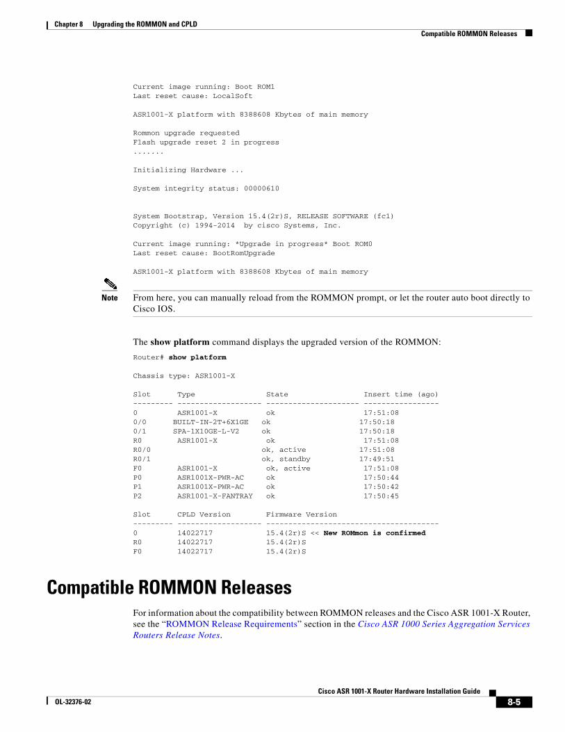
Chapter 8 Upgrading the ROMMON and CPLDCompatible ROMMON Releases
Current image running: Boot ROM1Last reset cause: LocalSoft
ASR1001-X platform with 8388608 Kbytes of main memory
Rommon upgrade requestedFlash upgrade reset 2 in progress.......
Initializing Hardware ...
System integrity status: 00000610
System Bootstrap, Version 15.4(2r)S, RELEASE SOFTWARE (fc1)Copyright (c) 1994-2014 by cisco Systems, Inc.
Current image running: *Upgrade in progress* Boot ROM0Last reset cause: BootRomUpgrade
ASR1001-X platform with 8388608 Kbytes of main memory
Note From here, you can manually reload from the ROMMON prompt, or let the router auto boot directly to Cisco IOS.
The show platform command displays the upgraded version of the ROMMON:
Router# show platform
Chassis type: ASR1001-X
Slot Type State Insert time (ago)--------- ------------------- --------------------- -----------------0 ASR1001-X ok 17:51:080/0 BUILT-IN-2T+6X1GE ok 17:50:180/1 SPA-1X10GE-L-V2 ok 17:50:18R0 ASR1001-X ok 17:51:08R0/0 ok, active 17:51:08R0/1 ok, standby 17:49:51F0 ASR1001-X ok, active 17:51:08P0 ASR1001X-PWR-AC ok 17:50:44P1 ASR1001X-PWR-AC ok 17:50:42P2 ASR1001-X-FANTRAY ok 17:50:45
Slot CPLD Version Firmware Version--------- ------------------- ---------------------------------------0 14022717 15.4(2r)S << New ROMmon is confirmedR0 14022717 15.4(2r)SF0 14022717 15.4(2r)S
Compatible ROMMON ReleasesFor information about the compatibility between ROMMON releases and the Cisco ASR 1001-X Router, see the “ROMMON Release Requirements” section in the Cisco ASR 1000 Series Aggregation Services Routers Release Notes.
8-5Cisco ASR 1001-X Router Hardware Installation Guide
OL-32376-02
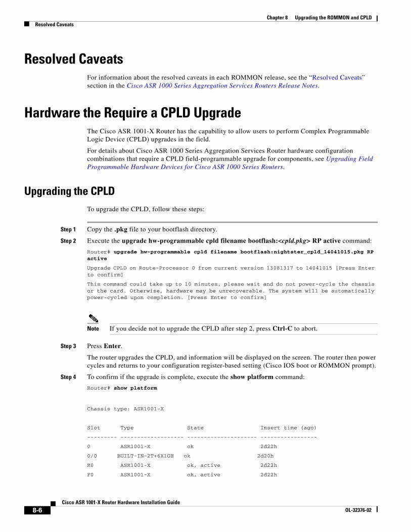
Chapter 8 Upgrading the ROMMON and CPLDResolved Caveats
Resolved CaveatsFor information about the resolved caveats in each ROMMON release, see the “Resolved Caveats” section in the Cisco ASR 1000 Series Aggregation Services Routers Release Notes.
Hardware the Require a CPLD UpgradeThe Cisco ASR 1001-X Router has the capability to allow users to perform Complex Programmable Logic Device (CPLD) upgrades in the field.
For details about Cisco ASR 1000 Series Aggregation Services Router hardware configuration combinations that require a CPLD field-programmable upgrade for components, see Upgrading Field Programmable Hardware Devices for Cisco ASR 1000 Series Routers.
Upgrading the CPLDTo upgrade the CPLD, follow these steps:
Step 1 Copy the .pkg file to your bootflash directory.
Step 2 Execute the upgrade hw-programmable cpld filename bootflash:<cpld.pkg> RP active command:
Router# upgrade hw-programmable cpld filename bootflash:nightster_cpld_14041015.pkg RP active
Upgrade CPLD on Route-Processor 0 from current version 13081317 to 14041015 [Press Enter to confirm]
This command could take up to 10 minutes, please wait and do not power-cycle the chassis or the card. Otherwise, hardware may be unrecoverable. The system will be automatically power-cycled upon completion. [Press Enter to confirm]
Note If you decide not to upgrade the CPLD after step 2, press Ctrl-C to abort.
Step 3 Press Enter.
The router upgrades the CPLD, and information will be displayed on the screen. The router then power cycles and returns to your configuration register-based setting (Cisco IOS boot or ROMMON prompt).
Step 4 To confirm if the upgrade is complete, execute the show platform command:
Router# show platform
Chassis type: ASR1001-X
Slot Type State Insert time (ago)
--------- ------------------- --------------------- -----------------
0 ASR1001-X ok 2d22h
0/0 BUILT-IN-2T+6X1GE ok 2d20h
R0 ASR1001-X ok, active 2d22h
F0 ASR1001-X ok, active 2d22h
8-6Cisco ASR 1001-X Router Hardware Installation Guide
OL-32376-02
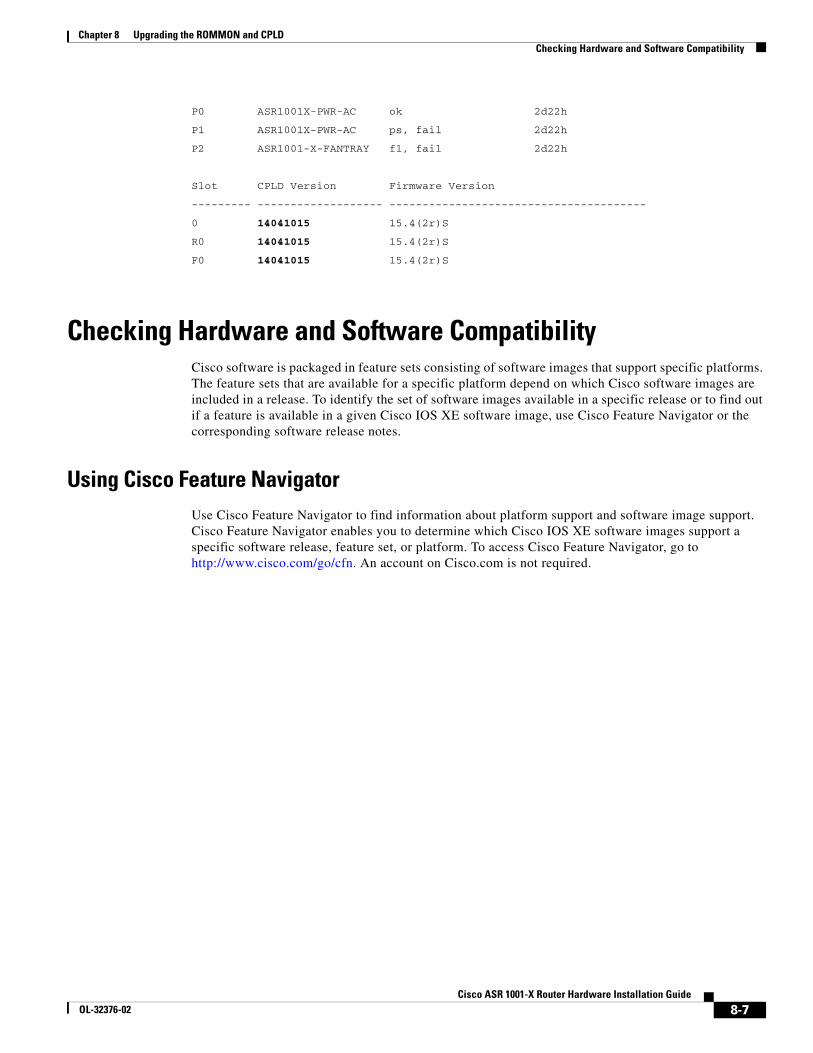
Chapter 8 Upgrading the ROMMON and CPLDChecking Hardware and Software Compatibility
P0 ASR1001X-PWR-AC ok 2d22h
P1 ASR1001X-PWR-AC ps, fail 2d22h
P2 ASR1001-X-FANTRAY f1, fail 2d22h
Slot CPLD Version Firmware Version
--------- ------------------- ---------------------------------------
0 14041015 15.4(2r)S
R0 14041015 15.4(2r)S
F0 14041015 15.4(2r)S
Checking Hardware and Software CompatibilityCisco software is packaged in feature sets consisting of software images that support specific platforms. The feature sets that are available for a specific platform depend on which Cisco software images are included in a release. To identify the set of software images available in a specific release or to find out if a feature is available in a given Cisco IOS XE software image, use Cisco Feature Navigator or the corresponding software release notes.
Using Cisco Feature NavigatorUse Cisco Feature Navigator to find information about platform support and software image support. Cisco Feature Navigator enables you to determine which Cisco IOS XE software images support a specific software release, feature set, or platform. To access Cisco Feature Navigator, go to http://www.cisco.com/go/cfn. An account on Cisco.com is not required.
8-7Cisco ASR 1001-X Router Hardware Installation Guide
OL-32376-02
Chapter 8 Upgrading the ROMMON and CPLDChecking Hardware and Software Compatibility
8-8Cisco ASR 1001-X Router Hardware Installation Guide
OL-32376-02
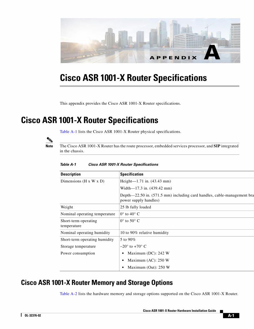
Cisco ASOL-32376-02
A
P P E N D I X Ant brac
Cisco ASR 1001-X Router Specifications
This appendix provides the Cisco ASR 1001-X Router specifications.
Cisco ASR 1001-X Router SpecificationsTable A-1 lists the Cisco ASR 1001-X Router physical specifications.
Note The Cisco ASR 1001-X Router has the route processor, embedded services processor, and SIP integrated in the chassis.
Cisco ASR 1001-X Router Memory and Storage OptionsTable A-2 lists the hardware memory and storage options supported on the Cisco ASR 1001-X Router.
Table A-1 Cisco ASR 1001-X Router Specifications
Description Specification
Dimensions (H x W x D) Height—1.71 in. (43.43 mm)
Width—17.3 in. (439.42 mm)
Depth—22.50 in. (571.5 mm) including card handles, cable-managemepower supply handles)
Weight 25 lb fully loaded
Nominal operating temperature 0° to 40° C
Short-term operating temperature
0° to 50° C
Nominal operating humidity 10 to 90% relative humidity
Short-term operating humidity 5 to 90%
Storage temperature –20° to +70° C
Power consumption • Maximum (DC): 242 W
• Maximum (AC): 250 W
• Maximum (Out): 250 W
A-1R 1001-X Router Hardware Installation Guide
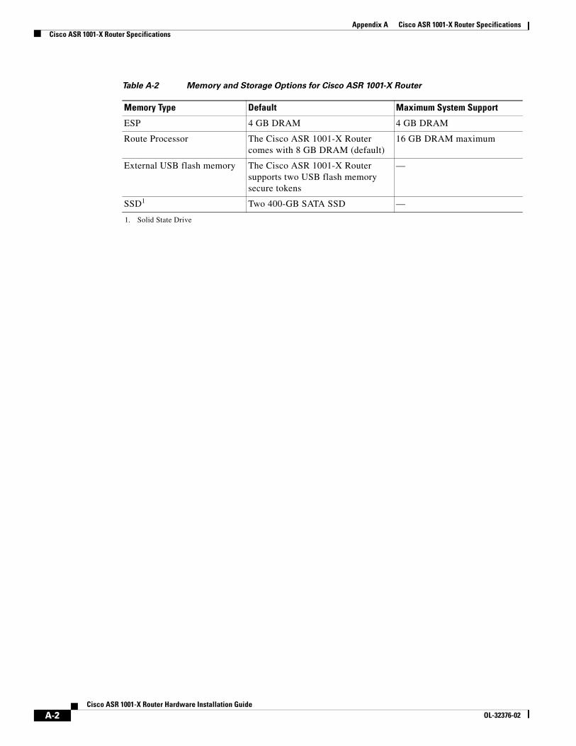
Appendix A Cisco ASR 1001-X Router SpecificationsCisco ASR 1001-X Router Specifications
Table A-2 Memory and Storage Options for Cisco ASR 1001-X Router
Memory Type Default Maximum System Support
ESP 4 GB DRAM 4 GB DRAM
Route Processor The Cisco ASR 1001-X Router comes with 8 GB DRAM (default)
16 GB DRAM maximum
External USB flash memory The Cisco ASR 1001-X Router supports two USB flash memory secure tokens
—
SSD1
1. Solid State Drive
Two 400-GB SATA SSD —
A-2Cisco ASR 1001-X Router Hardware Installation Guide
OL-32376-02
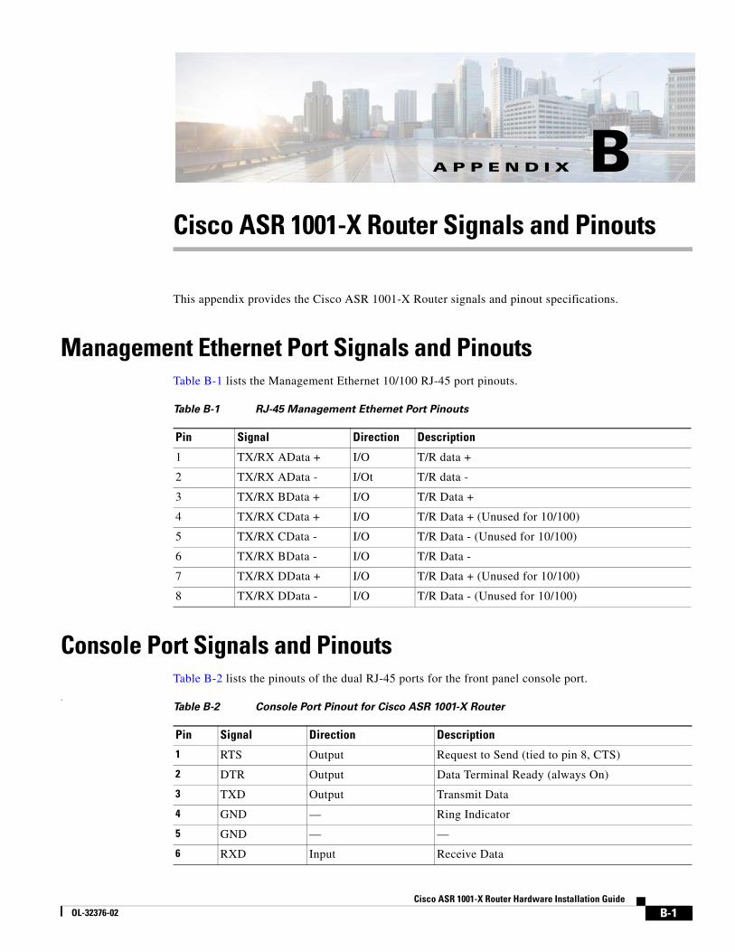
Cisco ASOL-32376-02
A
P P E N D I X B Cisco ASR 1001-X Router Signals and PinoutsThis appendix provides the Cisco ASR 1001-X Router signals and pinout specifications.
Management Ethernet Port Signals and PinoutsTable B-1 lists the Management Ethernet 10/100 RJ-45 port pinouts.
Console Port Signals and PinoutsTable B-2 lists the pinouts of the dual RJ-45 ports for the front panel console port.
.
Table B-1 RJ-45 Management Ethernet Port Pinouts
Pin Signal Direction Description
1 TX/RX AData + I/O T/R data +
2 TX/RX AData - I/Ot T/R data -
3 TX/RX BData + I/O T/R Data +
4 TX/RX CData + I/O T/R Data + (Unused for 10/100)
5 TX/RX CData - I/O T/R Data - (Unused for 10/100)
6 TX/RX BData - I/O T/R Data -
7 TX/RX DData + I/O T/R Data + (Unused for 10/100)
8 TX/RX DData - I/O T/R Data - (Unused for 10/100)
Table B-2 Console Port Pinout for Cisco ASR 1001-X Router
Pin Signal Direction Description
1 RTS Output Request to Send (tied to pin 8, CTS)
2 DTR Output Data Terminal Ready (always On)
3 TXD Output Transmit Data
4 GND — Ring Indicator
5 GND — —
6 RXD Input Receive Data
B-1R 1001-X Router Hardware Installation Guide
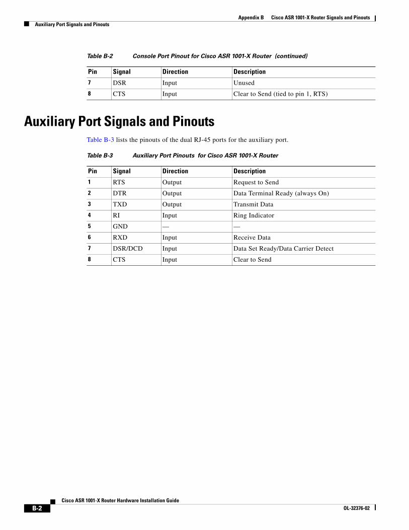
Appendix B Cisco ASR 1001-X Router Signals and PinoutsAuxiliary Port Signals and Pinouts
Auxiliary Port Signals and PinoutsTable B-3 lists the pinouts of the dual RJ-45 ports for the auxiliary port.
7 DSR Input Unused
8 CTS Input Clear to Send (tied to pin 1, RTS)
Table B-2 Console Port Pinout for Cisco ASR 1001-X Router (continued)
Pin Signal Direction Description
Table B-3 Auxiliary Port Pinouts for Cisco ASR 1001-X Router
Pin Signal Direction Description
1 RTS Output Request to Send
2 DTR Output Data Terminal Ready (always On)
3 TXD Output Transmit Data
4 RI Input Ring Indicator
5 GND — —
6 RXD Input Receive Data
7 DSR/DCD Input Data Set Ready/Data Carrier Detect
8 CTS Input Clear to Send
B-2Cisco ASR 1001-X Router Hardware Installation Guide
OL-32376-02