Embed Size (px)
Citation preview

170 West Tasman DriveSan Jose, CA 95134-1706USAhttp://www.cisco.com
Cisco Systems, Inc.Corporate Headquarters
Tel:800 553-NETS (6387)408 526-4000
Fax: 408 526-4100
Cisco 600 Series Installation and Operation GuideJuly 2000
Customer Order Number: DOC-7811190=Text Part Number: 78-11190-01

THE SPECIFICATIONS AND INFORMATION REGARDING THE PRODUCTS IN THIS MANUAL ARE SUBJECT TO CHANGE WITHOUT NOTICE. ALL STATEMENTS, INFORMATION, AND RECOMMENDATIONS IN THIS MANUAL ARE BELIEVED TO BE ACCURATE BUT ARE PRESENTED WITHOUT WARRANTY OF ANY KIND, EXPRESS OR IMPLIED. USERS MUST TAKE FULL RESPONSIBILITY FOR THEIR APPLICATION OF ANY PRODUCTS.
THE SOFTWARE LICENSE AND LIMITED WARRANTY FOR THE ACCOMPANYING PRODUCT ARE SET FORTH IN THE INFORMATION PACKET THAT SHIPPED WITH THE PRODUCT AND ARE INCORPORATED HEREIN BY THIS REFERENCE. IF YOU ARE UNABLE TO LOCATE THE SOFTWARE LICENSE OR LIMITED WARRANTY, CONTACT YOUR CISCO REPRESENTATIVE FOR A COPY.
The following information is for FCC compliance of Class A devices: This equipment has been tested and found to comply with the limits for a Class A digital device, pursuant to part 15 of the FCC rules. These limits are designed to provide reasonable protection against harmful interference when the equipment is operated in a commercial environment. This equipment generates, uses, and can radiate radio-frequency energy and, if not installed and used in accordance with the instruction manual, may cause harmful interference to radio communications. Operation of this equipment in a residential area is likely to cause harmful interference, in which case users will be required to correct the interference at their own expense.
The following information is for FCC compliance of Class B devices: The equipment described in this manual generates and may radiate radio-frequency energy. If it is not installed in accordance with Cisco’s installation instructions, it may cause interference with radio and television reception. This equipment has been tested and found to comply with the limits for a Class B digital device in accordance with the specifications in part 15 of the FCC rules. These specifications are designed to provide reasonable protection against such interference in a residential installation. However, there is no guarantee that interference will not occur in a particular installation.
Modifying the equipment without Cisco’s written authorization may result in the equipment no longer complying with FCC requirements for Class A or Class B digital devices. In that event, your right to use the equipment may be limited by FCC regulations, and you may be required to correct any interference to radio or television communications at your own expense.
You can determine whether your equipment is causing interference by turning it off. If the interference stops, it was probably caused by the Cisco equipment or one of its peripheral devices. If the equipment causes interference to radio or television reception, try to correct the interference by using one or more of the following measures:
• Turn the television or radio antenna until the interference stops.
• Move the equipment to one side or the other of the television or radio.
• Move the equipment farther away from the television or radio.
• Plug the equipment into an outlet that is on a different circuit from the television or radio. (That is, make certain the equipment and the television or radio are on circuits controlled by different circuit breakers or fuses.)
Modifications to this product not authorized by Cisco Systems, Inc. could void the FCC approval and negate your authority to operate the product.
The Cisco implementation of TCP header compression is an adaptation of a program developed by the University of California, Berkeley (UCB) as part of UCB’s public domain version of the UNIX operating system. All rights reserved. Copyright © 1981, Regents of the University of California.
NOTWITHSTANDING ANY OTHER WARRANTY HEREIN, ALL DOCUMENT FILES AND SOFTWARE OF THESE SUPPLIERS ARE PROVIDED “AS IS” WITH ALL FAULTS. CISCO AND THE ABOVE-NAMED SUPPLIERS DISCLAIM ALL WARRANTIES, EXPRESSED OR IMPLIED, INCLUDING, WITHOUT LIMITATION, THOSE OF MERCHANTABILITY, FITNESS FOR A PARTICULAR PURPOSE AND NONINFRINGEMENT OR ARISING FROM A COURSE OF DEALING, USAGE, OR TRADE PRACTICE.
IN NO EVENT SHALL CISCO OR ITS SUPPLIERS BE LIABLE FOR ANY INDIRECT, SPECIAL, CONSEQUENTIAL, OR INCIDENTAL DAMAGES, INCLUDING, WITHOUT LIMITATION, LOST PROFITS OR LOSS OR DAMAGE TO DATA ARISING OUT OF THE USE OR INABILITY TO USE THIS MANUAL, EVEN IF CISCO OR ITS SUPPLIERS HAVE BEEN ADVISED OF THE POSSIBILITY OF SUCH DAMAGES.
Access Registrar, AccessPath, Any to Any, Are You Ready, AtmDirector, Browse with Me, CCDA, CCDE, CCDP, CCIE, CCNA, CCNP, CCSI, CD-PAC, the Cisco logo, Cisco Certified Internetwork Expert logo, CiscoLink, the Cisco Management Connection logo, the Cisco NetWorks logo, the Cisco Powered Network logo, Cisco Systems Capital, the Cisco Systems Capital logo, Cisco Systems Networking Academy, the Cisco Systems Networking Academy logo, the Cisco Technologies logo, Fast Step, FireRunner, Follow Me Browsing, FormShare, GigaStack, IGX, Intelligence in the Optical Core, Internet Quotient, IP/VC, IQ Breakthrough, IQ Expertise, IQ FastTrack, IQ Readiness Scorecard, The IQ Logo, Kernel Proxy, MGX, Natural Network Viewer, NetSonar, Network Registrar, the Networkers logo, Packet, PIX, Point and Click Internetworking, Policy Builder, Precept, RateMUX, ReyMaster, ReyView, ScriptShare, Secure Script, Shop with Me, SlideCast, SMARTnet, SVX, The Cell, TrafficDirector, TransPath, VlanDirector, Voice LAN, Wavelength Router, Workgroup Director, and Workgroup Stack are trademarks; Changing the Way We Work, Live, Play, and Learn, Empowering the Internet Generation, The Internet Economy, and The New Internet Economy are service marks; and Aironet,

ASIST, BPX, Catalyst, Cisco, Cisco IOS, the Cisco IOS logo, Cisco Systems, the Cisco Systems logo, the Cisco Systems Cisco Press logo, CollisionFree, Enterprise/Solver, EtherChannel, EtherSwitch, FastHub, FastLink, FastPAD, FastSwitch, GeoTel, IOS, IP/TV, IPX, LightStream, LightSwitch, MICA, NetRanger, Post-Routing, Pre-Routing, Registrar, StrataView Plus, Stratm, TeleRouter, and VCO are registered trademarks of Cisco Systems, Inc. or its affiliates in the U.S. and certain other countries. All other trademarks mentioned in this document are the property of their respective owners. The use of the word partner does not imply a partnership relationship between Cisco and any other company. (0005R)
Cisco 600 Series Installation and Operation GuideCopyright © 2000, Cisco Systems, Inc.All rights reserved.


C O N T E N T S
About This Manual xvii
Document Objectives xvii
Document Organization xvii
Document Conventions xviii
Obtaining Documentation xx
World Wide Web xx
Documentation CD-ROM xx
Ordering Documentation xxi
Obtaining Technical Assistance xxi
Cisco Connection Online xxi
Technical Assistance Center xxii
Documentation Feedback xxiii
CH A P T E R 1 Overview of the Cisco 600 Series 1-1
Purpose 1-1
Product Description 1-2
System Features 1-3
System Memory 1-7
Environmental Constraints 1-7
Network Management and Security Applications 1-7
CH A P T E R 2 Installation Procedures 2-1
Installation Checklist 2-1
vCisco 600 Series Installation and Operation Guide
78-11190-01

Contents
Unpack the Shipping Carton 2-2
Hardware Requirements 2-3
Set Up the Hardware Environment 2-3
Connect the Management Port to the PC’s COM Port 2-4
Configure the PC’s COM Port 2-5
Possible Configurations 2-5
Connect Cables to the CPE 2-13
Power On the CPE 2-18
Next Step 2-19
Warnings and Cautions 2-19
CH A P T E R 3 Configuration Procedures for the Cisco 627 3-1
Introduction 3-1
Configuration Checklist 3-1
Log On to the Cisco Broadband Operating System 3-2
Determine the CBOS Version 3-2
Operation Modes 3-2
Configure Management Virtual Connections 3-3
Using Telnet 3-6
Connecting from a Windows NT or Windows 95 Machine 3-6
Connecting from a UNIX Machine 3-9
How to Keep Telnet from Timing Out During Your Session 3-9
Using a Trivial File Transfer Protocol Server 3-10
Using TFTP from a UNIX Machine 3-10
Using TFTP from a Windows NT Machine 3-11
Upgrade Software through Serial Download 3-12
Configure Line Coding 3-13
viCisco 600 Series Installation and Operation Guide
78-11190-01

Contents
Update the CBOS Prompt 3-18
Set Passwords 3-19
Save Configuration Changes 3-19
Evaluate System Activity and Performance 3-20
Retrieve Statistics 3-20
Interpret Statistics 3-21
CH A P T E R 4 Configuration Procedures for the Cisco 633 4-1
Introduction 4-1
Checklist 4-1
Log on to Cisco Broadband Operating System 4-2
Determine the CBOS Version 4-2
Operation Modes 4-3
Configure Interworking 4-3
Configure the Cisco 633 for Remote Management 4-4
Configuring External Routers 4-6
Upgrade Software through Serial Download 4-6
Update the CBOS Prompt 4-8
Set Passwords 4-8
Save Configuration Changes 4-9
CH A P T E R 5 Configuration Procedures for the Cisco 67x CPE Devices 5-1
Introduction 5-1
Configuration Checklist 5-1
Log On to the Cisco Broadband Operating System 5-3
Determine the CBOS Version 5-3
Operation Modes 5-4
viiCisco 600 Series Installation and Operation Guide
78-11190-01

Contents
Select a Connection Mode 5-5
Bridging Mode Procedures 5-5
Routing Mode Procedures 5-8
PPP Routing 5-8
RFC 1483 Routing 5-10
Configure the Ethernet Port (eth0) 5-11
Configure the WAN Ports and ATM Virtual Connections 5-12
Set ScalaRate for wan0-x 5-15
Create Routing Tables 5-16
Enable IP Filtering 5-17
Configure Applications 5-18
DHCP Client 5-18
DHCP Server 5-19
NAT 5-20
RADIUS Client 5-20
SNMP 5-22
SYSLOG Client 5-23
Telnet 5-24
TFTP Server 5-27
Web Server 5-30
Configure Timeout Values (Cisco 675, Cisco 678 in CAP mode only) 5-30
Configure Line Coding (Cisco 677 and Cisco 678 only) 5-31
Configure for CAP 5-31
Configure for DMT 5-34
Configure for G.Lite 5-36
Configure for DMT2 5-38
Configure for G.DMT 5-40
viiiCisco 600 Series Installation and Operation Guide
78-11190-01

Contents
Upgrade Software through Serial Download 5-42
Configure Static NAT 5-43
Configure Multiple PCs Connected to the CPE 5-44
Configure PPP over ATM with NAT 5-45
Update the CBOS Prompt 5-46
Set Passwords 5-47
Save Configuration Changes 5-48
Evaluate System Activity and Performance 5-48
Retrieve Statistics 5-49
Interpret Statistics 5-49
CH A P T E R 6 Troubleshooting 7-1
WAN Link and Power-Up Issues 7-1
Web Interface Password Lengths 7-2
Web Browser Compatibility 7-2
Serial Buffer Overflow 7-2
RADIUS Password and Username Lengths 7-3
Computers Running Linux Without term/termcap 7-3
Clearing PC Cache with ARP 7-3
RIP and Idle Timeouts 7-3
ADSL Parameters for the set interface command 7-4
Frequently Asked Questions about the WAN LNK LED 7-4
BERT Testing (Cisco 675, Cisco 675e and Cisco 676 only) 7-9
HP Test Set Configuration 7-9
Transmitting BERT Data 7-10
Receiving BERT Data 7-11
Cisco 600 Series CPE Configuration 7-11
ixCisco 600 Series Installation and Operation Guide
78-11190-01

Contents
A P PE N D I X A Connectors A-1
Rear Panel Connectors A-1
Serial Interface (Cisco 633) A-3
LAN Interface A-5
Management Interface A-7
ADSL/SDSL Port Interface A-9
Phone Port Interface A-10
A P PE N D I X B Specifications B-1
Physical Specifications B-1
Interface Specifications B-1
Serial Interface (Cisco 633) B-1
LAN Interface B-2
Management Interface B-2
ADSL/SDSL Interface B-3
Phone/Microfilter Interface (Cisco 675 and Cisco 678) B-3
Software Upgrade B-3
Power and Operating Requirements B-3
SDSL 2B1Q Transmission Specifications (Cisco 633 and Cisco 673) B-4
CAP RADSL Transmission Specifications (Cisco 675, Cisco 675e and Cisco 678) B-4
DMT Issue 1 Transmission Specifications (Cisco 676) B-5
DMT Issue 2 Transmission Specifications (Cisco 627, Cisco 677 and Cisco 678) B-5
xCisco 600 Series Installation and Operation Guide
78-11190-01

Contents
A P PE N D I X C EZ-DSL Microfilter Specifications C-1
Introduction C-1
Specifications C-1
In-Line Microfilter C-2
Wall-Mount Microfilter C-3
Regulatory Approvals C-5
G L O S S A R Y
I N D E X
xiCisco 600 Series Installation and Operation Guide
78-11190-01

Contents
xiiCisco 600 Series Installation and Operation Guide
78-11190-01

F I G U R E S
Figure 1-1 Cisco 600 series CPEs 1-3
Figure 2-1 Management Cable 2-3
Figure 2-2 Cisco 600 series CPE Management Port Cabling 2-4
Figure 2-3 Cisco 627 Connected through an Internal POTS Splitter 2-7
Figure 2-4 Cisco 633 Connected through an Internal POTS Splitter 2-8
Figure 2-5 Cisco 67x Connected through an Internal POTS Splitter 2-9
Figure 2-6 Cisco 627 Splitterless Configuration 2-10
Figure 2-7 Cisco 675 Splitterless Configuration 2-11
Figure 2-8 Cisco 675e, Cisco 676, Cisco 677 Splitterless Configuration 2-12
Figure 2-9 Cisco 678 Splitterless Configuration 2-13
Figure 2-10 Rear Panel Cabling for the Cisco 633 2-14
Figure 2-11 Rear Panel Cabling for the Cisco 627 2-15
Figure 2-12 Rear Panel Cabling for the Cisco 673, Cisco 675e, Cisco 676, and Cisco 677 2-16
Figure 2-13 Rear Panel Cabling for the Cisco 675 and Cisco 678 2-17
Figure 3-1 Remote System List Box 3-7
Figure 3-2 Telnet Preferences 3-8
Figure 3-3 Terminal Preferences 3-8
Figure 5-1 Remote System List Box 5-25
Figure 5-2 Telnet Preferences 5-26
Figure 5-3 Telnet Preferences 5-26
Figure A-1 Rear View of the Cisco 633 A-1
Figure A-2 Rear View of the Cisco 627 A-2
Figure A-3 Rear View of the Cisco 673, Cisco 675e, Cisco 676 and Cisco 677 A-2
xiiiCisco 600 Series Installation and Operation Guide
78-11190-01

Figures
Figure A-4 Rear View of the Cisco 675 and Cisco 678 A-2
Figure A-5 Front View of Serial Connector A-5
Figure A-6 Front View of Ethernet Connector A-6
Figure A-7 Front View of ATM25 Connector A-7
Figure A-8 Front View of RJ-45 End of the Serial Cable A-8
Figure A-9 Front View of DB-9 End of the Serial Cable A-9
Figure A-10 Front View of ADSL/SDSL Connector A-10
Figure A-11 Front View of Phone Connector A-11
Figure C-1 In-Line Microfilter and Cable C-2
Figure C-2 Wall Mount Microfilter C-4
xivCisco 600 Series Installation and Operation Guide
78-11190-01

T A B L E S
Table 1 Font Conventions xix
Table 2 Command Syntax Conventions xix
Table 3 Note, Timesaver, Tip, Caution, and Warning Conventions xx
Table 1-1 Maximum Receive and Transmit Rates (kbps) 1-2
Table 1-2 Cisco 600 Series CPE Hardware Features 1-4
Table 1-3 Standards Compliance 1-5
Table 1-4 Management Methods 1-6
Table 2-1 Installation Checklist 2-1
Table 2-2 Standard Shipment Contents 2-2
Table 2-3 Standard Cables Shipped 2-2
Table 2-4 Network Configurations 2-5
Table 3-1 Checklist for Configuration 3-1
Table 3-2 Status LEDs 3-20
Table 4-1 Checklist for Configuration 4-1
Table 5-1 Checklist for Router Configuration 5-1
Table 5-2 VPI/VCI Address Ranges 5-13
Table 5-3 Status LEDs 5-48
Table 6-1 WAN Link LED Blink Patterns 7-5
Table 6-2 BERT Header Bit Map 7-12
Table A-1 Rear Panel Connector A-3
Table A-2 12-in-1 to 5-in-1 Connector Pinouts A-4
Table A-3 Ethernet Connector Pinouts A-5
Table A-4 ATM25 Connector Pinouts A-6
xvCisco 600 Series Installation and Operation Guide
78-11190-01

Tables
Table A-5 Management Connector Pinouts A-7
Table A-6 ADSL/SDSL Connector Pinouts A-9
Table A-7 Phone Connector Pinouts A-10
Table B-1 SDSL 2B1Q Transmission Specifications B-4
Table B-2 CAP RADSL Transmission Specifications B-4
Table B-3 DMT Issue 1 Transmission Specifications B-5
Table B-4 DMT Issue 2 Transmission Specifications B-5
Table C-1 In-Line Microfilter Pinouts C-2
Table C-2 Wall Mount Microfilter Pinouts C-4
Table C-3 Jack Labeling and Wire Color Codes C-5
xviCisco 600 Series Installation and Operation Guide
78-11190-01

About This Manual
This manual, developed for system managers and network managers, contains information about installing, configuring, and operating the Cisco 600 series customer premises equipment (CPE) devices.
Document ObjectivesThe objectives of this manual are to describe all initial hardware installation and basic configuration procedures for the Cisco 600 series CPE devices.
Document OrganizationThis guide is organized into the following chapters and appendixes:
Chapter/Appendix Title Topics Covered
Chapter 1 Overview of the Cisco 600 Series
Provides information on functions and features of the Cisco 600 series CPEs.
Chapter 2 Installation Procedures Describes the installation procedures for the Cisco 600 series CPEs.
xviiCisco 600 Series Installation and Operation Guide
78-11190-01

About This ManualDocument Conventions
Document ConventionsThis publication uses the document conventions listed in Table 1, Table 2, and Table 3.
Chapter 3 Configuration Procedures for the Cisco 627
Describes the steps for configuring the Cisco 627 for operation. This chapter also describes in detail how Cisco has implemented the Telnet, and Trivial File Transfer Protocol (TFTP) general applications for the Cisco 627.
Chapter 4 Configuration Procedures for the Cisco 633
Describes the steps for configuring the Cisco 633 for operation. This chapter also describes in detail how Cisco has implemented the Telnet, Syslog, and TFTP general applications for the Cisco 633.
Chapter 5 Configuration Procedures for the Cisco 67x CPE Devices
Describes the steps for configuring the Cisco 67x routers for operation. This chapter also describes in detail how Cisco has implemented the Telnet, Syslog, Remote Authentication Dial-In User Service (RADIUS), and TFTP general applications for these CPEs. This applies to the Cisco 673, Cisco 675, Cisco 675e, Cisco 676, Cisco 677, and Cisco 678.
Chapter 6 Troubleshooting Contains information about known issues and how to resolve them.
Appendix A Connectors Provides details on the cables and connectors.
Appendix B Specifications Contains a list of physical, interface and operating specifications.
Appendix C EZ-DSL Microfilter Specifications
Provides details on the EZ-DSL microfilter. This applies to the Cisco 627, Cisco 675, Cisco 675e, Cisco 676, Cisco 677, and Cisco 678 only.
Glossary Provides ADSL technology definitions.
Chapter/Appendix Title Topics Covered
xviiiCisco 600 Series Installation and Operation Guide
78-11190-01

About This ManualDocument Conventions
Table 1 Font Conventions
Convention Definition Sample
Times bold Text body font used for arguments, commands, keywords, and punctuation that is part of a command that the user enters in text and command environments.
This is similar to the UNIX route command.
Times italic Text body font used for publication names and for emphasis.
Refer to the Cisco Broadband Operating System UserGuide for further details.
courier Example font used for screen displays, prompts, and scripts.
Are you ready to continue? [Y]
courier bold Example font used to indicate what the user enters in examples of command environments.
Login: root
Table 2 Command Syntax Conventions
Convention Definition Sample
vertical bars ( | ) Separate alternative, mutually exclusive elements offset-list {in | out} offset
square brackets ([ ]) Indicate optional elements [no] offset-list {in | out} offset
braces ({ }) Indicate a required choice offset-list {in | out} offset
braces within square brackets ([{ }])
Indicate a required choice within an optional element
[{letter/number}Enter]
boldface Indicates commands and keywords that are entered literally as shown
[no] offset-list {in | out} offset
italics Indicate arguments for which you supply values
Note In contexts that do not allow italics, arguments are enclosed in angle brackets (< >).
offset-list {in | out} offset
xixCisco 600 Series Installation and Operation Guide
78-11190-01

About This ManualObtaining Documentation
Obtaining Documentation
World Wide WebYou can access the most current Cisco documentation on the World Wide Web at http://www.cisco.com, http://www-china.cisco.com, or http://www-europe.cisco.com.
Documentation CD-ROMCisco documentation and additional literature are available in a CD-ROM package, which ships with your product. The Documentation CD-ROM is updated monthly. Therefore, it is probably more current than printed documentation. The CD-ROM package is available as a single unit or as an annual subscription.
Table 3 Note, Timesaver, Tip, Caution, and Warning Conventions
Convention Description
Note Means reader take note. Notes contain helpful suggestions or references to material not covered in the manual.
Timesaver Means the described action saves time. You can save time by performing the action described in the paragraph.
Caution Means reader be careful. In this situation, you might do something that could result in equipment damage or loss of data.
Warning Means danger. You are in a situation that could cause bodily injury. Before you work on any equipment, you must be aware of the hazards involved with electrical circuitry and familiar with standard practices for preventing accidents. To see translated versions of warnings, refer to the Regulatory Compliance and Safety Information document that accompanied the device.
xxCisco 600 Series Installation and Operation Guide
78-11190-01

About This ManualObtaining Technical Assistance
Ordering DocumentationRegistered CCO users can order the Documentation CD-ROM and other Cisco Product documentation through our online Subscription Services at http://www.cisco.com/cgi-bin/subcat/kaojump.cgi.
Nonregistered CCO users can order documentation through a local account representative by calling Cisco’s corporate headquarters (California, USA) at 408 526-4000 or, in North America, call 800 553-NETS (6387).
Obtaining Technical AssistanceCisco provides Cisco Connection Online (CCO) as a starting point for all technical assistance. Warranty or maintenance contract customers can use the Technical Assistance Center. All customers can submit technical feedback on Cisco documentation using the web, e-mail, a self-addressed stamped response card included in many printed docs, or by sending mail to Cisco.
Cisco Connection OnlineCisco continues to revolutionize how business is done on the Internet. Cisco Connection Online is the foundation of a suite of interactive, networked services that provides immediate, open access to Cisco information and resources at anytime, from anywhere in the world. This highly integrated Internet application is a powerful, easy-to-use tool for doing business with Cisco.
CCO’s broad range of features and services helps customers and partners to streamline business processes and improve productivity. Through CCO, you will find information about Cisco and our networking solutions, services, and programs. In addition, you can resolve technical issues with online support services, download and test software packages, and order Cisco learning materials and merchandise. Valuable online skill assessment, training, and certification programs are also available.
Customers and partners can self-register on CCO to obtain additional personalized information and services. Registered users may order products, check on the status of an order and view benefits specific to their relationships with Cisco.
xxiCisco 600 Series Installation and Operation Guide
78-11190-01

About This ManualObtaining Technical Assistance
You can access CCO in the following ways:
• WWW: www.cisco.com
• Telnet: cco.cisco.com
• Modem using standard connection rates and the following terminal settings: VT100 emulation; 8 data bits; no parity; and 1 stop bit.
– From North America, call 408 526-8070
– From Europe, call 33 1 64 46 40 82
You can e-mail questions about using CCO to [email protected].
Technical Assistance CenterThe Cisco Technical Assistance Center (TAC) is available to warranty or maintenance contract customers who need technical assistance with a Cisco product that is under warranty or covered by a maintenance contract.
To display the TAC web site that includes links to technical support information and software upgrades and for requesting TAC support, use www.cisco.com/techsupport.
To contact by e-mail, use one of the following:
In North America, TAC can be reached at 800 553-2447 or 408 526-7209. For other telephone numbers and TAC e-mail addresses worldwide, consult the following web site: http://www.cisco.com/warp/public/687/Directory/DirTAC.shtml.
Language E-mail Address
English [email protected]
Hanzi (Chinese) [email protected]
Kanji (Japanese) [email protected]
Hangul (Korean) [email protected]
Spanish [email protected]
Thai [email protected]
xxiiCisco 600 Series Installation and Operation Guide
78-11190-01

About This ManualObtaining Technical Assistance
Documentation FeedbackIf you are reading Cisco product documentation on the World Wide Web, you can submit technical comments electronically. Click Feedback in the toolbar and select Documentation. After you complete the form, click Submit to send it to Cisco.
You can e-mail your comments to [email protected].
To submit your comments by mail, for your convenience many documents contain a response card behind the front cover. Otherwise, you can mail your comments to the following address:
Cisco Systems, Inc.Document Resource Connection170 West Tasman DriveSan Jose, CA 95134-9883
We appreciate and value your comments.
xxiiiCisco 600 Series Installation and Operation Guide
78-11190-01

About This ManualObtaining Technical Assistance
xxivCisco 600 Series Installation and Operation Guide
78-11190-01

Cisco 600 Series78-11190-01
C H A P T E R 1
Overview of the Cisco 600 SeriesPurposeThis chapter provides an overview of the Cisco 600 series customer premises equipment (CPE) devices including the following CPE models:
• Cisco 627
• Cisco 633
• Cisco 673
• Cisco 675
• Cisco 675e
• Cisco 676
• Cisco 677
• Cisco 678
This chapter also describes the general applications available with the Cisco 600 series CPEs.
Note This chapter documents general product features available in the Cisco 600 series CPEs. Please refer to the Release Notes for the Cisco Broadband Operating System available on CCO for a current list of upgraded software features.
1-1 Installation and Operation Guide

Chapter 1 Overview of the Cisco 600 SeriesProduct Description
Product DescriptionThe Cisco 600 series CPEs provide home connectivity to a digital subscriber line (DSL) service provider network over a DSL/ATM physical layer. Table 1-1 shows the maximum receive and transmit rates for the Cisco 600 series CPEs:
1 Discrete Multi-Tone2 Carrierless Amplitude and Phase modulation
Table 1-1 Maximum Receive and Transmit Rates (kbps)
CPE Model/Encoding Receive (Downstream) Transmit (Upstream)
Cisco 627
DMT1 8032 864
G.Lite 1536 512
G.DMT 8032 864
Cisco 633 1168 1168
Cisco 673 1168 1168
Cisco 675 7168 1088
Cisco 675e 7168 1088
Cisco 676 9200 832
Cisco 677
DMT 8032 864
G.Lite 1536 512
G.DMT 8032 864
Cisco 678
DMT 8032 864
CAP2 7168 1088
G.Lite 1536 512
1-2Cisco 600 Series Installation and Operation Guide
78-11190-01

Chapter 1 Overview of the Cisco 600 SeriesProduct Description
Note Despite the maximum transmission rates listed above, the actual maximum operative rate is determined by the service provider’s central office (CO) equipment. Line length and line conditions can also have a great effect on transmission rate.
Figure 1-1 shows a front view of the generic Cisco 600 series CPEs.
Figure 1-1 Cisco 600 series CPEs
System Features
Hardware Features
Table 1-2 summarizes the hardware features of the Cisco 600 series CPEs.
3526
6
Cisco 6xx
WAN
LAN
ACTLNK
ALARMPOWER
ACT
LNK
1-3Cisco 600 Series Installation and Operation Guide
78-11190-01

Chapter 1 Overview of the Cisco 600 SeriesProduct Description
1 Discrete Multi-Tone Issue 12 Discrete Multi-Tone Issue 23 Symmetrical digital subscriber line4 Asymmetric digital subscriber line
Table 1-2 Cisco 600 Series CPE Hardware Features
Feature 627 633 673 675 675e 676 677 678
DMT Issue 11-based ADSL physical layer
!
DMT Issue 22 (T1.413), G.Lite (G.992.2)-based ADSL physical layer
! ! !
SDSL3 interface with 2B1Q line code
! !
CAP ADSL4 interface ! ! !G.DMT-based ADSL physical layer
! !
Serial interface with Frame Relay encapsulation
!
ATM25 interface !ATM cell delineation adherent to ITU-T I.432
! ! ! ! ! ! ! !
Supports ATM Forum-compliant PVCs)
! ! ! ! ! ! ! !
Autonegotiating 10BaseT or 100BaseTX Ethernet interface, compliant with IEEE 802.3 and 802.3u Fast Ethernet
! ! ! ! ! !
Status LEDs indicating ATM25/Ethernet/Serial and ADSL/SDSL activity
! ! ! ! ! ! ! !
1-4Cisco 600 Series Installation and Operation Guide
78-11190-01

Chapter 1 Overview of the Cisco 600 SeriesProduct Description
Software Features
Table 1-3 summarizes the software standards supported by the Cisco 600 series CPEs.
Standards Compliance
1 American National Standards Institute
Routing Support (Cisco 67x)
• Internet Protocol (RFC 791)
– User Datagram Protocol (RFC 768)
Table 1-3 Standards Compliance
Standard 627 633 673 675 675e 676 677 678
DMT (ANSI T1.413) Issue 1 !DMT (ANSI T1.413) Issue 2 ! ! !Point-to-Point Protocol (PPP) (RFC 1661)
! ! ! ! ! !
Multiprotocol Encapsulation over ATM Adaptation Layer 5 (RFC 1483)
! ! ! ! ! ! ! !
ATM Forum UNI Version 3.1 PVC
! ! ! ! ! ! ! !
IEEE 802.3 and 802.3u 10BaseT and 100BaseTX Physical Layer Specification
! ! ! ! ! !
IEEE 802.1d Transparent Learning Bridging
! ! ! ! ! ! !
PPP Bridging Control Protocol (BCP) (RFC 1638)
! ! ! ! ! !
Splitterless ADSL Transceivers G.992.2
! ! !
1-5Cisco 600 Series Installation and Operation Guide
78-11190-01

Chapter 1 Overview of the Cisco 600 SeriesProduct Description
– Internet Control Message Protocol (RFC 792)
– Ethernet Address Resolution Protocol (RFC 826)
– RIP version 1 updating of routing tables
• Static routing
• Remote Authentication Dial-In User Service (RADIUS) Security and Accounting (RFC 2058, RFC 2059)
• Dynamic Host Configuration Protocol (DHCP) client and server
• Network Address Translation (NAT)
Bridging Support
• Transparent learning bridge:
– Multiprotocol Encapsulation over ATM Adaptation Layer 5 (RFC 1483)
– PPP (Bridging Control Protocol) (RFC 1638)
• Management channel support for remote configuration/management
Management
Table 1-4 summarizes the management methods supported by the Cisco 600 series CPEs.
Table 1-4 Management Methods
Management method 627 633 673 675 675e 676 677 678
HTML browser interface ! ! ! ! ! ! !Command-line interface ! ! ! ! ! ! ! !Telnet support ! ! ! ! ! ! ! !TFTP1 ! ! ! ! ! ! ! !SNMP2 MIB3 support ! ! ! ! !Multilevel password protection ! ! ! ! ! ! ! !Enables different logins through serial management port
!
1-6Cisco 600 Series Installation and Operation Guide
78-11190-01

Chapter 1 Overview of the Cisco 600 SeriesNetwork Management and Security Applications
1 Trivial File Transfer Protocol2 Simple Network Management Protocol3 Management Information Base
System MemoryThe Cisco 600 series CPEs are equipped with 4 MB of DRAM.
Environmental ConstraintsThe Cisco 600 series CPEs operate in an ambient temperature environment of 32° to 104°F (0° to 40°C) and may be stored in an ambient temperature environment of – 40°to 185°F (– 40°to 85°C).
Note Electrical equipment generates heat. Ambient air temperature might not be adequate to cool equipment to acceptable operating temperatures without adequate circulation. Ensure that the room in which you operate the CPE has adequate air circulation.
Be careful not to block the air vents on the CPE.
Network Management and Security ApplicationsThe Cisco 627 and Cisco 633 support the following network system management applications:
• Telnet server described in “Using Telnet” section on page 3-6.
• TFTP server described in “Using a Trivial File Transfer Protocol Server” section on page 3-10.
The general applications supported by the Cisco 673, Cisco 675, Cisco 675e, Cisco 676, Cisco 677, and Cisco 678 are:
• DHCP client and server
• NAT
1-7Cisco 600 Series Installation and Operation Guide
78-11190-01
Chapter 1 Overview of the Cisco 600 SeriesNetwork Management and Security Applications
• Ping
• RADIUS
• RIP
• SNMP
• SYSLOG client
• Telnet server
• TFTP server and client
• Traceroute
• Web server (HTTP server)
For more information on each of these applications, see the “Configure Applications” section on page 5-18.
1-8Cisco 600 Series Installation and Operation Guide
78-11190-01

Cisco 600 Series78-11190-01
C H A P T E R 2
Installation ProceduresThis chapter provides information about installing the Cisco 600 series CPE devices.
Installation ChecklistTable 2-1 lists the tasks to be completed when installing the Cisco 600 series CPE.
Table 2-1 Installation Checklist
Installation Procedures Page Number
Unpack the Shipping Carton 2-2
Set Up the Hardware Environment:
• Connect the Management Port to the PC’s COM Port
• Configure the PC’s COM Port
• Possible Configurations
• Connect Cables to the CPE
• Power On the CPE
2-4
2-5
2-5
2-13
2-18
2-1 Installation and Operation Guide

Chapter 2 Installation ProceduresUnpack the Shipping Carton
Unpack the Shipping CartonCheck the shipping carton carefully to ensure that the contents include the items you ordered. You can identify the Cisco 600 series CPE by the product name on the top of the unit at the end with the LEDs.
The contents of your carton might vary depending on your service provider. Tables 2-2 and 2-3 show a list of the standard contents of a Cisco 600 series CPE shipment.
If any items you ordered were not delivered, contact Cisco.
Table 2-2 Standard Shipment Contents
Contents Description
Cisco 600 series CPE Cisco DSL CPE for home/office use.
Quick Start for the Cisco 6xx Quick start information for the specific Cisco 600 series CPE model.
Table 2-3 Standard Cables Shipped
Cable 627 633 673 675 675e 676 677 678
Power supply—Worldwide AC power adapter
! ! ! ! ! ! ! !
ADSL/SDSL cable—RJ-11 telephone cable (14 ft)
! ! ! ! ! ! ! !
ATM25 cable—Category 5 cable (6 ft)
!
Ethernet cable—Yellow Ethernet category 5 “no-hub” twisted pair crossover cable (6 ft)
! ! ! ! ! !
SERIAL cable (Blue)—12-in-1 Smart Serial connector
!
2-2Cisco 600 Series Installation and Operation Guide
78-11190-01

Chapter 2 Installation ProceduresHardware Requirements
Hardware RequirementsThe following hardware is necessary to configure the Cisco 600 series CPE:
• PC with a standard terminal emulation program or a dumb terminal, with a DB-9 COM port.
Note If only a DB-25 serial port is available on the computer, a DB-9-male-to-DB-25-female adapter is also needed to connect the management cable to the computer.
• Management cable (RJ-45-to-DB-9) like the one in Figure 2-1 to connect the CPE to the PC or dumb terminal you will use to configure it. You can order one from Cisco or provide your own. See Appendix A, “Connectors” for information on connector pin assignments.
Figure 2-1 Management Cable
Set Up the Hardware EnvironmentThis section describes how to connect the Cisco 600 series CPE.
1842
9
2-3Cisco 600 Series Installation and Operation Guide
78-11190-01

Chapter 2 Installation ProceduresSet Up the Hardware Environment
Note Electrical equipment generates heat. Ambient air temperature might not be adequate to cool equipment to acceptable operating temperatures without adequate circulation. Ensure that the room in which you operate the CPE has adequate air circulation.
Be careful not to block the air vents on the CPE.
Connect the Management Port to the PC’s COM Port
Step 1 Connect the RJ-45 connector on the management cable to the MGMT port on the CPE.
Step 2 Connect the other end of the management cable to the computer’s COM port. If your computer is equipped only with a DB-25 serial port, you need a DB-9-male-to-DB-25-female adapter.
Figure 2-2 Cisco 600 series CPE Management Port Cabling
3537
7
110
Cisco 6xx
PWR WALLMGMT
2-4Cisco 600 Series Installation and Operation Guide
78-11190-01

Chapter 2 Installation ProceduresSet Up the Hardware Environment
Configure the PC’s COM Port For the best access to the CBOS, use your terminal emulation program (such as HyperTerminal in Windows) to set your COM protocol to the following settings:
• Baud rate: 38400 bps recommended (standard 9600 bps possible)
• Data bits: 8
• Parity: None
• Stop bits: 1
• Flow control: None
Possible ConfigurationsThis section shows you different ways of connecting your Cisco 600 series CPE to your telephone and computer equipment, depending on whether or not your telephone equipment is connected to a POTS splitter.
Table 2-4 shows the configurations that will work with each Cisco 600 series CPE model.
Back-to-Back Cabling (Cisco 633 and Cisco 673 only)
You can connect two Cisco 633s or Cisco 673s in a “back-to-back” configuration. This allows one CPE to terminate the traffic of a second CPE without central office (CO) equipment. This configuration can be used as a low-cost solution for communicating between two locations at a distance greater than Ethernet’s
Table 2-4 Network Configurations
Configuration 627 633 673 675 675e 676 677 678
POTS Splitter ! ! ! ! ! ! ! !EZ-DSL (Splitterless) ! ! ! ! ! !Back-to-back (bridging mode only)
! !
2-5Cisco 600 Series Installation and Operation Guide
78-11190-01

Chapter 2 Installation ProceduresSet Up the Hardware Environment
100-meter range. The two locations must be directly connected, for example, through some internally owned telephone system wiring in a campus-type environment.
Step 1 At the first location, connect one end of the SDSL cable into the WALL port on one of the Cisco 633 or Cisco 673 units. Connect the other end of the SDSL cable into the wall jack.
Step 2 At the second location, connect one end of the second SDSL cable into the WALL port of the second Cisco 633 or Cisco 673 unit. Connect the other end of the second SDSL cable into the wall jack.
Step 3 Configure the CPE that you want to terminate traffic to operate in CO mode and the other to operate in CPE mode. See the “Attention Back-to-Back Connection Users” section on page 4-5 for more information.
Note Back-to-back configuration works in bridging mode only.
POTS Splitter Configuration (Required for the Cisco 627)
A POTS splitter separates data signals from voice signals on your telephone line. The POTS splitter works by running a separate data line from the voice line, so that the CPE has a dedicated cable for data transmission. Figure 2-3, Figure 2-4, and Figure 2-5 show telephone equipment connected to a POTS splitter.
2-6Cisco 600 Series Installation and Operation Guide
78-11190-01

Chapter 2 Installation ProceduresSet Up the Hardware Environment
Figure 2-3 Cisco 627 Connected through an Internal POTS Splitter
TelephoneNID
Cisco 3600
3538
5
Cisco 4101
ATM25
Ethernet
Cisco 627
Voice
Data
POTSSplitter
2-7Cisco 600 Series Installation and Operation Guide
78-11190-01

Chapter 2 Installation ProceduresSet Up the Hardware Environment
Figure 2-4 Cisco 633 Connected through an Internal POTS Splitter
TelephoneNID
Cisco 2500, Cisco 2600,or Cisco 3600
3545
0
Cisco 4101
Serial
Ethernet
Cisco 633
Voice
Data
POTSSplitter
2-8Cisco 600 Series Installation and Operation Guide
78-11190-01

Chapter 2 Installation ProceduresSet Up the Hardware Environment
Figure 2-5 Cisco 67x Connected through an Internal POTS Splitter
Note The POTS splitter can also be installed adjacent to the telephone network interface device (NID) on the outside of the house.
EZ-DSL™ (Splitterless) Configuration
Note This configuration applies to the Cisco 627, Cisco 675, Cisco 675e, Cisco 676, Cisco 677, and Cisco 678 only.
In the EZ-DSL configuration, your telephone equipment is not connected to a POTS splitter. Without a POTS splitter and under certain circumstances, transient noise from a telephone can interfere with the router’s operation, and the router can cause noise on the telephone line. To prevent this from happening, small
TelephoneNID
3538
6
Ethernet
Hub
Cisco 67x
Voice
Data
POTSSplitter
2-9Cisco 600 Series Installation and Operation Guide
78-11190-01

Chapter 2 Installation ProceduresSet Up the Hardware Environment
microfilters must be connected to the telephone lines. If you implement an EZ-DSL configuration, your installation landscape should look similar to Figure 2-6, Figure 2-7, Figure 2-8, or Figure 2-9.
Figure 2-6 Cisco 627 Splitterless Configuration
Cisco 3600
Cisco 4101
ATM25
EthernetMicrofilter
Microfilter
TelephoneNID
3545
4
Data
Cisco 627
2-10Cisco 600 Series Installation and Operation Guide
78-11190-01

Chapter 2 Installation ProceduresSet Up the Hardware Environment
Figure 2-7 Cisco 675 Splitterless Configuration
Microfilter
Microfilters
TelephoneNID
3537
8
Data Ethernet
Hub
Cisco 675
2-11Cisco 600 Series Installation and Operation Guide
78-11190-01

Chapter 2 Installation ProceduresSet Up the Hardware Environment
Figure 2-8 Cisco 675e, Cisco 676, Cisco 677 Splitterless Configuration
Microfilter
Microfilters
TelephoneNID
3537
9
Data Ethernet
Hub
Cisco 675e/Cisco 676/Cisco 677
2-12Cisco 600 Series Installation and Operation Guide
78-11190-01

Chapter 2 Installation ProceduresSet Up the Hardware Environment
Figure 2-9 Cisco 678 Splitterless Configuration
Note The microfilters do not work if connected improperly. For connection instructions, see Appendix C, “EZ-DSL Microfilter Specifications.”
Connect Cables to the CPEThis section describes how to connect cables to the CPE and to your telephone and computer systems.
Microfilter
Microfilters Microfilter
TelephoneNID
3151
9
Data Ethernet
Hub
Cisco 678
2-13Cisco 600 Series Installation and Operation Guide
78-11190-01

Chapter 2 Installation ProceduresSet Up the Hardware Environment
Cabling Diagrams
Figures 2-10 through 2-13 show how to connect cables to the rear panels of Cisco 600 series CPEs.
Figure 2-10 Rear Panel Cabling for the Cisco 633
PWR SERIAL MGMT WALL
2459
1
Powercable
12-in-1 Smart Serial cable
SDSLcable
2-14Cisco 600 Series Installation and Operation Guide
78-11190-01

Chapter 2 Installation ProceduresSet Up the Hardware Environment
Figure 2-11 Rear Panel Cabling for the Cisco 627
PWR ATM25 MGMT WALL
1843
2
Powercable
ATM25cable
ADSLcable
2-15Cisco 600 Series Installation and Operation Guide
78-11190-01

Chapter 2 Installation ProceduresSet Up the Hardware Environment
Figure 2-12 Rear Panel Cabling for the Cisco 673, Cisco 675e, Cisco 676, and
Cisco 677
2855
3
Powercable
Ethernetcable
DSLcable
PWR ENET MGMT WALL
2-16Cisco 600 Series Installation and Operation Guide
78-11190-01

Chapter 2 Installation ProceduresSet Up the Hardware Environment
Figure 2-13 Rear Panel Cabling for the Cisco 675 and Cisco 678
Cabling Instructions
To connect the cables to the Cisco 600 series CPE:
Step 1 Plug the power cable into the back of the unit.
Step 2 Plug the network cable into the ATM25 port of the Cisco 627, or the ENET port of the Cisco 67x.
For the Cisco 633, connect one end of the serial cable to the SERIAL port. Connect the other end to your router.
2455
5
Powercable
Ethernetcable
ADSLcable
PWR ENET MGMT WALL PHONE
Phonecable
2-17Cisco 600 Series Installation and Operation Guide
78-11190-01

Chapter 2 Installation ProceduresPower On the CPE
For the Cisco 627, connect the other end of the network cable to your premises router, for example, a Cisco 3600 series router.
For the Cisco 67x, if the customer premises has only a single Ethernet-equipped computer, attach the Cisco 600 series CPE to the computer’s Ethernet adapter with the crossover cable provided. Otherwise, connect the Cisco 600 series CPE Ethernet port to an Ethernet hub via a straight-through cable (not provided).
Step 3 Connect the telephone cable to the WALL port. Connect the other end of the telephone cable in the appropriate configuration as discussed in the “Possible Configurations” section on page 2-5.
Step 4 (Optional step for the Cisco 678) Plug the microfilter into the PHONE port. Then plug the telephone into the microfilter.
Note Never connect a telephone directly to the PHONE port of the Cisco 678; this affects the CPE’s performance.
Step 5 (Optional step for the Cisco 675) Plug the telephone into the PHONE port. The telephone can be connected directly to the PHONE port of the Cisco 675 because it uses a built-in microfilter.
Power On the CPE
Step 1 Connect power to the Cisco 600 series CPE by plugging the power supply into an appropriate electrical outlet.
Note Use only the Cisco-approved power supply that shipped with the CPE as your power supply.
Note Cisco recommends that you unplug your CPE when you are not using it.
2-18Cisco 600 Series Installation and Operation Guide
78-11190-01

Chapter 2 Installation ProceduresNext Step
Step 2 When you have powered up the Cisco 600 series CPE, check that the Power LED is ON.
Step 3 If the Power LED is not lit, immediately remove the barrel power connector from the Cisco 600 series CPE. Refer to Chapter 6, “Troubleshooting,” for information.
Note To power down the Cisco 600 series CPE, unplug the power supply cable from the Cisco 600 series CPE rear panel PWR connector.
Next StepNow that you have installed and powered on your Cisco 600 series CPE, you must configure it.
To configure the Cisco 627, see Chapter 3, “Configuration Procedures for the Cisco 627.”
To configure the Cisco 633, see Chapter 4, “Configuration Procedures for the Cisco 633.”
To configure the Cisco 673, Cisco 675, Cisco 67e, Cisco 676, Cisco 677 or Cisco 678, see Chapter 5, “Configuration Procedures for the Cisco 67x CPE Devices.”
Warnings and Cautions
Warning To prevent dangerous overloading of the power circuit, read the label on the bottom of the Cisco 600 series CPE that indicates maximum power load ratings. Failure to follow these rating guidelines could result in a dangerous situation.
2-19Cisco 600 Series Installation and Operation Guide
78-11190-01
Chapter 2 Installation ProceduresWarnings and Cautions
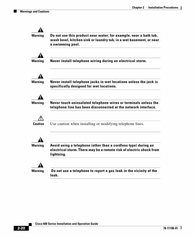
Warning Do not use this product near water; for example, near a bath tub, wash bowl, kitchen sink or laundry tub, in a wet basement, or near a swimming pool.
Warning Never install telephone wiring during an electrical storm.
Warning Never install telephone jacks in wet locations unless the jack is specifically designed for wet locations.
Warning Never touch uninsulated telephone wires or terminals unless the telephone line has been disconnected at the network interface.
Caution Use caution when installing or modifying telephone lines.
Warning Avoid using a telephone (other than a cordless type) during an electrical storm. There may be a remote risk of electric shock from lightning.
Warning Do not use a telephone to report a gas leak in the vicinity of the leak.
2-20Cisco 600 Series Installation and Operation Guide
78-11190-01

Cisco 600 Series78-11190-01
C H A P T E R 3
Configuration Procedures for the Cisco 627IntroductionThis chapter provides information about configuring your Cisco 627. Your unit is preconfigured for full operation. However, you might need to configure the Cisco 627 for management virtual connections (VCs).
Configuration ChecklistTable 3-1 identifies the configuration procedures you might need.
Table 3-1 Checklist for Configuration
Configuration Procedures Page Number
Log On to the Cisco Broadband Operating System 3-2
Configure Management Virtual Connections 3-3
Update the CBOS Prompt 3-18
Set Passwords 3-19
Save Configuration Changes 3-19
Evaluate System Activity and Performance 3-20
Retrieve Statistics 3-20
3-1 Installation and Operation Guide

Chapter 3 Configuration Procedures for the Cisco 627Log On to the Cisco Broadband Operating System
Log On to the Cisco Broadband Operating SystemAfter connecting all cables to the Cisco 627 and powering it on, start the terminal emulation program and press the Enter key until the Cisco Broadband Operating System (CBOS) welcome screen appears. When you see the welcome screen, you can log on to CBOS.
Hello!Expanding CBOS image...CBOS v2.3.5.012 - Release Software
Password:
Determine the CBOS VersionAfter you log on to CBOS, you can use the show version command to determine the CBOS version of the Cisco 627:
cbos# show version
Operation ModesCBOS also has two modes of operation: exec and enable. The CBOS defaults to exec mode when you log on. The exec mode grants read-only (command execution) privileges to a user.
To write changes to NVRAM, you must work in enable mode. To invoke enable mode:
Step 1 At the command line, enter:
cbos> enable
Step 2 Enter the enable password when CBOS prompts you:
Password:
3-2Cisco 600 Series Installation and Operation Guide
78-11190-01

Chapter 3 Configuration Procedures for the Cisco 627Configure Management Virtual Connections
Note If you have not set any passwords, press the Enter key when the system prompts you for a password.
Configure Management Virtual ConnectionsYour system comes preconfigured for full and immediate network operation. However, you might need to manage your Cisco 627 directly over the network. To do this, you must establish and set management virtual connections (VCs).
Note You must be in the enable mode to perform these procedures.
Each interface is expressed as atmx, where x is either 0 or 1. The atm0 interface is reserved for ATM25. The atm1 interface is used for the ADSL remote interface.
The valid range for VPI is 0 to 255. 0 to 65535 is the valid range for VCI addresses.
Note The Cisco 627 is configured with atm0 using VPI/VCI 0/34 by default. The atm0 interface is used for management. Cisco recommends that you do not change VPI/VCI values for atm0.
Changing VPI Settings
Step 1 To set the VPI number to 2, enter:
cbos# set interface atm1 vpi 2
Step 2 To begin using this connection with the new settings, enter:
cbos# set interface atm1 enable
Step 3 To verify your setting:
cbos# show interface atm1
3-3Cisco 600 Series Installation and Operation Guide
78-11190-01

Chapter 3 Configuration Procedures for the Cisco 627Configure Management Virtual Connections
A display similar to the following will appear on your screen:
atm1 RFC1483 Ethernet HWaddr 00:E0:D0:01:19:7F IP address 10.0.1.1 Mask 255.255.255.0 MTU 1500 Metric 0 RX packets 0 errors 0 TX packets 0 errors 0 Port is currently enabled with link status VCI 34 VPI 2 Severely Errored Frame Count:0 Data rate 6944 Kbps down; 480 Kbps up Line capacity 7456 Kbps down; 480 Kbps up SNR Margin 8 dB; previous 8 dB Attenuation 13.0 dB; previous 13.0 dBStatus: Last Self-Test Result:Not Available Modem Microcode: 0x1119be0dConfigured: Trellis Coding: Enabled Echo Cancellation: Disabled FDQ Adaptation: Enabled Rate Adaptation: Normal Overhead Framing: Mode-3 Bit-Swapping: Disabled ATM Payload Scrambling: Disabled PGA-Cutback: 0 dBActual: FEC Redundancy Bytes: Interl. Path: downstream: 16, upstream 0 Fast Path: downstream: 0, upstream 0 Interleaver Depth: downstream: 0, upstream 0 Trellis Coding: Not-Used Echo Cancellation: Not-Used FDQ Adaptation: In-Use Overhead Framing: Mode-0 (910 compatible) Bit-Swapping: Not-UsedLast Line Fault: NONEATM Statistics: Interleaved-Path Counters: HEC errors: 0 LOCD events: 0 Fast-Path Counters: HEC errors: 0 LOCD events: 0DSL Statistics: Superframes: 956 Corrected Superframes: 0 (+INF) Uncorrected Superframes: 0 LOCD Retrains 0
3-4Cisco 600 Series Installation and Operation Guide
78-11190-01

Chapter 3 Configuration Procedures for the Cisco 627Configure Management Virtual Connections
LOS Retrains: 0 LOF/RFI Retrains: 0 ES Events: 0 Time Trained (h:m:s) 0:00:16 Trained...
Step 4 To save the new WAN port configuration, enter:
cbos# write
Step 5 To exit CBOS, enter:
cbos# quit
Note To close an ATM management connection, enter: set interface atmx disable. To set the ATM25 management VPI, repeat the previous steps substituting atm0 for atm1.
Changing VCI Settings
Step 1 To set the VCI number to 32, enter:
cbos# set interface atm0 vci 32
To verify your setting:
cbos# show interface atm0
A display similar to the following will appear on your screen:
atm0 RFC1483 Ethernet Hwaddr 00:E0:D0:01:19:7FIP address 192.168.1.100 Mask 255.255.255.0MTU 1500 Metric 0RX packets 0 errors 0TX packets 0 errors 0Port is currently disabled with no link statusVCI 32 VPI 0
Step 2 To begin using this connection with the new settings, enter:
cbos# set interface atm0 enable
3-5Cisco 600 Series Installation and Operation Guide
78-11190-01

Chapter 3 Configuration Procedures for the Cisco 627Using Telnet
Step 3 To save the new WAN port configuration, enter:
cbos# write
Step 4 To exit CBOS, enter:
cbos# quit
Note To close an ATM management connection, enter: set interface atmx disable. To set the ADSL ATM VCI, repeat the previous steps substituting atm1 for atm0.
Using TelnetTelnet provides a command-line interface for remote login connections between machines on many networks, including the Internet. To establish a Telnet connection to the CPE, Telnet must be enabled in CBOS.
Caution Before closing a Telnet connection, always enter exit or quit at the cbos# prompt.
Connecting from a Windows NT or Windows 95 Machine
Step 1 Click the Start button.
Step 2 Select the Run... option.
Step 3 When the Run box appears, enter telnet in the space provided.
Step 4 Click the OK button. The Connect menu appears.
Step 5 Select the Remote System... option from the Connect menu. The Remote System List Box appears. (See Figure 3-1.)
3-6Cisco 600 Series Installation and Operation Guide
78-11190-01

Chapter 3 Configuration Procedures for the Cisco 627Using Telnet
Figure 3-1 Remote System List Box
Step 6 Enter the atm0 IP address of your modem in the Host Name box and click Connect. The system then initiates a connection session. When connection is initiated, information similar to the following displays:
User Access VerificationPassword:
Note Press the Enter key several times to establish a connection.
Step 7 Provide the logon and password information. After the system authenticates your password, you have access to the CBOS.
Note You can log on to the CPE using no password by pressing the Enter key at the password prompt. Refer to the “Set Passwords” section on page 3-19 for more information about how to set and change passwords.
Notice to Windows Users
Windows’ Telnet client does not support NVT (Network Virtual Terminal) or any extra form of option negotiation. However, if you are going to use the Windows Telnet client, complete the following steps to set your terminal settings.
3-7Cisco 600 Series Installation and Operation Guide
78-11190-01

Chapter 3 Configuration Procedures for the Cisco 627Using Telnet
Step 1 When the Telnet window appears, go to the Terminal drop-down menu, and click Preferences. (See Figure 3-2.)
Figure 3-2 Telnet Preferences
Step 2 Set the terminal settings on the Terminal Preferences menu to the values shown in Figure 3-3.
Figure 3-3 Terminal Preferences
3-8Cisco 600 Series Installation and Operation Guide
78-11190-01

Chapter 3 Configuration Procedures for the Cisco 627Using Telnet
Notice to Linux Users
When you run Linux without installing the Term/Termcap database, the message BAD ADDRESS displays during a connection attempt. Use the original Linux installation disks to install the Term/Termcap database.
Connecting from a UNIX MachineThe following procedure describes how to log on to your modem from a UNIX system:
Step 1 Enter the following at your prompt:
telnet IP address of atm0
After you have connected, information similar to the following appears on your display:
Cisco Broadband Operating SystemCBOS (tm) 2.3.5.012 - Release SoftwareCopyright (c) 1986-1999 by cisco Systems, Inc.cbos>
Step 2 Provide the login and password information. After the system authenticates your password, you have access to CBOS.
How to Keep Telnet from Timing Out During Your SessionTelnet sessions time out after a period of inactivity. Enter the following commands to keep the Telnet client from timing out.
cbos# set telnet timeout offcbos# write
The set telnet timeout off setting is not saved in NVRAM after a reboot. You must explicitly set it for every session.
3-9Cisco 600 Series Installation and Operation Guide
78-11190-01

Chapter 3 Configuration Procedures for the Cisco 627Using a Trivial File Transfer Protocol Server
Using a Trivial File Transfer Protocol ServerThe Trivial File Transfer Protocol (TFTP) enables you to transfer files to and from your modem. Your system runs a tftp daemon that enables remote users who have TFTP client software, to transfer files to and from the system. The TFTP client is enabled and disabled from the CBOS or the Web Management Interface.
Caution For security reasons, Cisco recommends that you disable the TFTP application, except when uploading or downloading a file.
Software Updates
Use the TFTP utility to transfer a new software image from Cisco to your system, where the filename equals nsrouter.c627.x.ima, where x is the release number.
Versions of CBOS 2.3 or higher use the filename format c627.x.bin, where x is the release number.
Archives
Use the TFTP utility to back up a copy of your configuration file before changing it,
so you can easily recover the old file if necessary. The naming conventions for the configuration file are:
• When using the put option of the tftp command, you must name the file nscfg.cfg.
• When using the get option of the tftp command, name the file any name that a standard text editor can view and edit.
Using TFTP from a UNIX MachineFor information on the UNIX TFTP client, access the online manual on your UNIX system. At the command-line prompt, enter:
man tftp
3-10Cisco 600 Series Installation and Operation Guide
78-11190-01

Chapter 3 Configuration Procedures for the Cisco 627Using a Trivial File Transfer Protocol Server
The manual page for TFTP appears. The TFTP UNIX man page contains all the information you need to establish and invoke a remote TFTP session.
Using TFTP from a Windows NT MachineBefore attempting to use TFTP, make sure of the following:
• On the Cisco 627, TFTP is enabled and the IP address of the ATMx port is the same IP address used in Step 2 of the following procedure.
• The ATMx port is enabled, and the VCI/VPI is set correctly on it.
• The remote host computer must be configured for RFC 1483 Logical Link Control (LLC)/Subnetwork Access Protocol (SNAP) encapsulation if the PC is directly connected to the CPE through the atm0 interface, or verify the IP connectivity between the PC and the CPE.
To use TFTP:
Step 1 Start a DOS session and verify connectivity from the PC to the CPE. Enter:
C:>ping IP address
Step 2 Enter one of the following commands:
C:>tftp -i IP address put nsrouter software image filename C:>tftp -i IP address put system configuration config filename C:>tftp -i IP address put DSP firmware file name
where IP address is the IP address of the ATMx port.
Where necessary, implement the following options:
-i - Sets the transfer mode to binary mode.
put - Uploads a file to that IP address.
Note The CPE might take up to 2 minutes to upgrade the firmware. Wait until the management console reappears before rebooting the CPE.
3-11Cisco 600 Series Installation and Operation Guide
78-11190-01

Chapter 3 Configuration Procedures for the Cisco 627Upgrade Software through Serial Download
Step 3 Be sure that you reboot the device to activate the new image. When you log back on to your system after the reboot, use the following command to verify the version of the firmware that is active:
cbos# show version
Notice to Windows 95 Users
Windows 95 does not have a TFTP client. If you want to utilize TFTP on a Windows 95 system, you must install a TFTP client from a third-party vendor on your system. One way to locate a TFTP client is to use an Internet search engine to locate a vendor who sells a TFTP client. Some TFTP clients are provided as share or freeware on the Internet. By request, Cisco will provide a TFTP client.
Upgrade Software through Serial DownloadYou can upgrade software on your CPE using the serial interface:
Step 1 Enter the following settings through a serial console connected to your system:38.4 KbaudNo parity8 data bits1 stop bitNo flow control
Step 2 To turn debug monitor on, enter:
debug monitor on
Step 3 To save your changes, enter:
write
Step 4 To reboot the device, enter:
reboot
After the modem reboots, press Enter twice. The prompt should change to =>.
3-12Cisco 600 Series Installation and Operation Guide
78-11190-01

Chapter 3 Configuration Procedures for the Cisco 627Configure Line Coding
Step 5 To erase sector 0, enter:
es 0
Repeat this step for sectors 1 through 5.
Step 6 To start serial download, enter:
df 10008000
Step 7 Use a terminal emulation application, such as Hyperterminal, to start an Xmodem download of a new Cisco 67x image.
Step 8 When the download is complete, the following message appears:
Transferred xxxxxxxx bytes
Record the number of bytes transferred.
Step 9 To program the area of memory to Flash, enter:
pb 10008000 fef00000 xxxxxxxx
where xxxxxxxx is the value recorded in Step 6.
Step 10 To turn debug monitor off, enter:
m0
Step 11 To reboot, enter:
rb
Configure Line CodingThe Cisco 627 allows you to choose transmission protocols to match your network configuration by changing the CPE’s configuration file and operating system. You will use the TFTP to transfer files to and from the CPE. This section describes procedures to configure the Cisco 627 for G.Lite and G.DMT protocols.
Note Changes to your CPE must be coordinated with the central office equipment.
3-13Cisco 600 Series Installation and Operation Guide
78-11190-01

Chapter 3 Configuration Procedures for the Cisco 627Configure Line Coding
Configure for DMT2
Step 1 Verify the connection from the router to the location where the correct software image is stored. This location is provided by your service provider. Typically, you use the ping command for this step.
Step 2 Enable TFTP by entering:
cbos#set tftp enabledTFTP is enabled
Step 3 Set the remote address for the TFTP host computer by entering:
cbos # tftp remote ip address
This command tells the CPE to accept TFTP transfers from a specific IP address. An example remote IP address would be 192.168.35.4. This address is an example only; do not use it to configure the router.
Note If you do not have the CPE address, consult your network administrator.
For more information about TFTP, see “Using a Trivial File Transfer Protocol Server” section on page 3-10.
Step 4 To start the file transfer from a PC, start a DOS session and enter the following command:
C:>tftp –i CPE IP address put image_filename
To start the file transfer from a UNIX machine, enter the following commands:
root@staten-</6xx>tftptftp> mode binarytftp> put CPE IP address:image_filenameSent 922294 bytes in 54.9 seconds
3-14Cisco 600 Series Installation and Operation Guide
78-11190-01

Chapter 3 Configuration Procedures for the Cisco 627Configure Line Coding
Where necessary, implement the following values:
Substitute the filename for the software image update. See the latest Release Notes for the Cisco Broadband Operating System available on CCO for the appropriate filenames to use.
Caution Do not turn off the power to the router until after the file transfer is completed.
Step 5 Be sure to reboot the CPE to activate the new image. When you log back in to the CPE after the reboot, use the show version command to verify the version of the firmware that is active. Note the DMT firmware version.
Sample Output of Configuration Session for DMT2
cbos#set tftp enabledTFTP is enabled
cbos#tftp image TFTP_server_IP_address image_filenameStarting download... Downloading in progress...... done. Saving image...........done. Please reboot the CPE for the new downlcbos#rebootHello!C6xx self-update code: Release 2.3.5.012NOTE: Do not power off router until update is finished!
Decompressing router...Erasing FLASH......Programming...Decompressing monitor...Erasing FLASH.........Programming...
-i Sets the transfer mode to binary mode
get Downloads a file to a specified IP address
put Uploads a file onto that IP address
3-15Cisco 600 Series Installation and Operation Guide
78-11190-01

Chapter 3 Configuration Procedures for the Cisco 627Configure Line Coding
Finished. Rebooting...Hello!Expanding CBOS image...CBOS v2.3.5.012 - Release Software
User Access VerificationPassword:
cbos>enablePassword:
cbos#show version
Cisco Broadband Operating SystemCBOS (tm) 627 Software (C627-I-M), Version v2.3.0.053, RELEASE SOFTWARECopyright (c) 1986-1999 by cisco Systems, Inc.Compiled Feb 13 2000 17:36:16Monitor build 111 (Feb 13 2000 17:37:07)
Configure for G.DMT
Before the CPE can be configured for G.DMT, the .full image must be loaded. See the latest Release Notes for the Cisco Broadband Operating Sytsem for the appropriate filenames to use. The central office hardware must be correctly configured to accept a G.DMT service user.
Step 1 Enter the following command:
cbos# set interface atm1 standard g.992.1
Step 2 Be sure to retrain the CPE to activate the new line code. When the CPE is retrained, use the show interface atm1 command to verify the G.DMT standard is active. Note that the standard configuration for the .full image is DMT2.
Note Changes made to the running configuration must be written to NVRAM for changes to be seen on reboot.
3-16Cisco 600 Series Installation and Operation Guide
78-11190-01

Chapter 3 Configuration Procedures for the Cisco 627Configure Line Coding
Sample Output of Configuration Session for G.DMT
cbos#set interface atm1 standardSET INTERFACE WANx STANDARD requires one of the following argumentsT1.413G.dmt (G992.1)
cbos#set interface atm1 standard g.992.1Note: Change will take effect on next retrain.
cbos#show interface atm1atm1 ADSL Physical Port Line TrainedActual Configuration: Overhead Framing: 3 Trellis Coding: Disabled Standard Compliance: g.992.1 Downstream Data Rate: 8032 Kbps Upstream Data Rate: 864 Kbps Interleave S Downstream: 1 Interleave D Downstream: 64 Interleave R Downstream: 2 Interleave S Upstream: 4 Interleave D Upstream: 8 Interleave R Upstream: 16 Modem Microcode: G96 DSP version: 0 Operating State: Showtime/Data ModeConfigured: Echo Cancellation: Disabled Overhead Framing: 3 Coding Gain: Auto TX Power Attenuation: 0dB Trellis Coding: Enabled Bit Swapping: Disabled Standard Compliance: Multimode Remote Standard Compliance:g.992.1 Tx Start Bin: 0x6 Tx End Bin: 0x1f Data Interface: Utopia L1Status: Local SNR Margin: 3.5dB Local Coding Gain: 0.0dB Local Transmit Power: 12.5dB Local Attenuation: 28.5dB Remote Attenuation: 18.5dBLocal Counters: Interleaved RS Corrected Bytes: 0
3-17Cisco 600 Series Installation and Operation Guide
78-11190-01

Chapter 3 Configuration Procedures for the Cisco 627Update the CBOS Prompt
Interleaved Symbols with CRC Errors: 2 No Cell Delineation Interleaved: 0 Out of Cell Delineation Interleaved: 0 Header Error Check Counter Interleaved:0 Count of Severely Errored Frames: 0 Count of Loss of Signal Frames: 0Remote Counters: Interleaved RS Corrected Bytes: 0 Interleaved Symbols with CRC Errors: 0 No Cell Delineation Interleaved: 0 Header Error Check Counter Interleaved:0 Count of Severely Errored Frames: 0 Count of Loss of Signal Frames: 0
Update the CBOS PromptThe default Cisco 627 system prompt is cbos#. The command prompt is limited to 8 characters. You can change this prompt to a unique subscriber identifier as shown in the following example.
Step 1 Log on to the CBOS using either the serial or Telnet interfaces. Refer to the “Using Telnet” section on page 3-6 for more information on how to use Telnet to log on to the CBOS.
Step 2 To change the default prompt to 4412883 as the subscriber identifier, enter:
cbos# set prompt 44128834412883#
Step 3 To save your changes, enter:
4412883# write
Step 4 To exit the CBOS, enter:
4412883# quit
3-18Cisco 600 Series Installation and Operation Guide
78-11190-01

Chapter 3 Configuration Procedures for the Cisco 627Set Passwords
Set PasswordsAfter you have configured your system, you should pick new passwords for both the enable and exec modes. Keep in mind that the enable mode provides all the functionality of a system administrator for the CPE. Examples of good and bad passwords are:
• Good Password—77ta99y (Do not use the sample password.)
• Bad Passwords—Passwords such as your name; or your street address, or home telephone number are too predictable.
Use the set password command to change both the enable and exec passwords as in the following:
Step 1 To change the password enter:
cbos# set password mode new password
Example:
set password enable 33Low44PassMeset password exec 44High55Pass
Step 2 To save your changes, enter:cbos# write
Step 3 To exit CBOS, enter:cbos# quit
Save Configuration ChangesUse the write command to save any changes you have made during provisioning to the NVRAM configuration file:
cpe627# write
Caution If you do not use the write command after changes, all the changes you made during your current session will be lost when you reboot the Cisco 627.
3-19Cisco 600 Series Installation and Operation Guide
78-11190-01

Chapter 3 Configuration Procedures for the Cisco 627Evaluate System Activity and Performance
Evaluate System Activity and PerformanceTable 3-2 describes the LEDs and their status.
Retrieve StatisticsThe stats command shows information about the number of packets transmitted and received and activity information about general applications.
Table 3-2 Status LEDs
LED Label Full Name Description
WAN-LNK WAN Link When this light is ON, it indicates that a link has been established on the WAN port. The WAN-LNK light blinks steadily during ADSL line training activities. When the light is solid, the system is connected and trained.
WAN-ACT WAN Activity When this light blinks, it indicates that the WAN port is transmitting or receiving data.
LAN-LNK ATM25 LAN Link When this light is ON, it indicates that a link has been established on the ATM-25 port.
Note For some ATM-25 routers or NICs, this light may not be on till data is sent to the modem.
LAN-ACT ATM25 LAN Activity When this light blinks, it indicates activity on the ATM-25 port.
PWR Power Light When this light is Green, the system is ON and working correctly.
ALARM Alarm Light When the light is Red, the system is ON but indicates a problem that needs to be resolved.
3-20Cisco 600 Series Installation and Operation Guide
78-11190-01

Chapter 3 Configuration Procedures for the Cisco 627Interpret Statistics
To retrieve statistics:
Step 1 To see a list of variables, enter:
cbos# stats
Step 2 To display specific statistics, enter:
cbos# stats variable from list
Step 3 To exit the CBOS, enter:
cbos# quit
Interpret StatisticsUse the stats atm0 and show interface atm1 commands to retrieve key statistics regarding ADSL performance. These statistics are:
• CRC Errors—Number of CRC errors. CRC errors might occur when the ATM traffic rate is faster than the ADSL rate, causing ATM cells to be dropped. This corrupts the AAL5 logical packets. CRC errors might also be an indication of excessive noise on the DSL line.
• Errored Seconds—Number of Superframe CRC errors. If this field is incremented, the user data path is encountering uncorrected errors.
• Rx’ed Blocks—Number of blocks received by the unit. A block is 250 milliseconds. This statistic is reset whenever the modem trains.
• Tx’ed Blocks—Number of blocks transmitted by the unit. A block is 250 milliseconds. This statistic is reset whenever the modem trains.
• Corrected/Uncorrected Blocks—The modem can correct a block containing errors. If the block correction fails, the block is counted as an uncorrected block and discarded.
• Attenuation—Difference in decibels (dB) between the power level received at the near end versus the power level transmitted from the far end. The attenuation range is 0 to 63 dB in 1 db increments. Attenuation is calculated every 10 seconds.
3-21Cisco 600 Series Installation and Operation Guide
78-11190-01

Chapter 3 Configuration Procedures for the Cisco 627Interpret Statistics
• Signal-to-Noise (SNR) Margin—Amount of increased received signal noise (in decibels) relative to the signal noise power level the unit is designed to tolerate without disconnecting from the network. The SNR Margin range is -64.0 to +63 dB in 1 dB increments. SNR Margin is calculated every 10 seconds. The previous value is moved to the Previous SNR Margin field.
• Previous SNR Margin—Last SNR Margin measurement, which occurs approximately every 10 seconds.
• Operation, Administration, Maintenance (OAM) Loopback Cells—The Cisco 627 supports the Operation, Administration, and Maintenance (OAM) F5 loopback cell to verify end-to-end ATM network connectivity. The OAM-F5 loopback cell is generated by a network-side system. The cell is injected into a specific virtual circuit along with the normal user traffic flow. The cell is carried unmodified by each intermediate ATM switching node until it arrives at the circuit's other endpoint such as the Cisco 627. The receiving endpoint modifies the cell payload to indicate that the cell has been looped back and transmits this new cell back into the ATM circuit. It is relayed by each intermediate node until it arrives at the original transmitting endpoint. The receipt of this cell indicates a valid end-to-end connection between the two endpoints over the intervening ATM network.
3-22Cisco 600 Series Installation and Operation Guide
78-11190-01

Cisco 600 Series78-11190-01
C H A P T E R 4
Configuration Procedures for the Cisco 633IntroductionThis chapter provides instructions for configuring the Cisco 633 SDSL modem. Configuration procedures vary depending on how your Cisco 633 is configured when shipped. You must be in enable mode to perform these configuration procedures.
Note Cisco recommends that only one command-line application at a time be used to configure the Cisco 633. For example, Telnet and the serial management interface should not be used simultaneously.
ChecklistTable 4-1 Checklist for Configuration
Configuration Procedures Page Number
Log on to Cisco Broadband Operating System 4-2
Configure Interworking 4-3
Configure the Cisco 633 for Remote Management 4-4
4-1 Installation and Operation Guide

Chapter 4 Configuration Procedures for the Cisco 633Log on to Cisco Broadband Operating System
Log on to Cisco Broadband Operating SystemAfter connecting all the cables to the Cisco 633 and powering it on, start the terminal emulation program and press the Enter key until the CBOS login screen appears. When you see the welcome screen, you can log on to CBOS.
Hello!Expanding CBOS image...CBOS v2.3.5.012
User Access VerificationPassword:
Note If you have not set any passwords for the Cisco 633, press the Enter key when the system prompts you for a password to enter CBOS.
Determine the CBOS VersionAfter you log on to CBOS and before proceeding any further with your configuration process, check the version of CBOS to verify that the version number and date reflect the most recent firmware update:
cbos> show version
Configuring External Routers 4-6
Upgrade Software through Serial Download 4-6
Update the CBOS Prompt 4-8
Set Passwords 4-8
Save Configuration Changes 4-9
Table 4-1 Checklist for Configuration (continued)
Configuration Procedures Page Number
4-2Cisco 600 Series Installation and Operation Guide
78-11190-01

Chapter 4 Configuration Procedures for the Cisco 633Configure Interworking
If the CBOS version is earlier than 2.2.0, get the latest version from Cisco. See the Trivial File Transfer Protocol (tftp) command in the Cisco Broadband Operating System User Guide for more information on how to update the Cisco 633 firmware. You can also update the CBOS version through the management port also.
Operation ModesCBOS implements two operational modes: exec and enable. CBOS defaults to exec mode when you log in. The exec mode grants program execution (read-only) privileges to a user. To read or write changes to nonvolatile random-access memory (NVRAM), you must work in enable mode. To invoke the enable mode:
Step 1 At the exec mode command-line prompt, enter:
cbos> enable
Step 2 Enter a password when CBOS prompts you:
cbos> enablePassword:
Note If you have not set any passwords for the Cisco 633, press the Enter key when the system prompts you for a password to enter CBOS. If you have not preset a password, you can still log on to CBOS.
You are now in enable mode. The system prompt appears:
cbos#
Configure InterworkingTo translate from Frame Relay (FR) to ATM, you must first configure an IWF data path.
4-3Cisco 600 Series Installation and Operation Guide
78-11190-01

Chapter 4 Configuration Procedures for the Cisco 633Configure the Cisco 633 for Remote Management
Step 1 Close the virtual WAN port for which you are creating an IWF:
set int wan0-1 close
Step 2 Configure a Data Link Connection ID (DLCI) on the FR (serial) network:
set int serial0-1 dlci 17
Note Enter a DLCI range between 16 and 1007.
Step 3 Repeat steps 1 and 2 to create multiple IWF data paths.
Step 4 Write the changes to Non-Volatile Read Only Memory (NVRAM):
write
Step 5 Reboot the Cisco 633:
reboot
Configure the Cisco 633 for Remote ManagementRemote management allows you to configure the Cisco 633.
Note The WAN0-0 and SER0-0 interfaces are reserved for remote management.
Step 1 Close the WAN0-0 port:
set int wan0-0 close
Step 2 Decide which side of the network you are on, either the FR network (SER0-0) or the ATM (WAN0-0) network. The following steps show configuration for the ATM network.
Step 3 Configure an IP address for the WAN0-0 interface:
set int wan0-0 ip 10.0.1.0
4-4Cisco 600 Series Installation and Operation Guide
78-11190-01

Chapter 4 Configuration Procedures for the Cisco 633Configure the Cisco 633 for Remote Management
Step 4 Configure a netmask address for the WAN0-0 interface:
set int wan0-0 mask 255.255.255.0
Step 5 Add a static IP route to and from the remote network. This allows data to pass between your Cisco 633 and the remote network.
set route add ip x.x.x.x gw wan0-0
where x.x.x.x is the static IP route to and from the remote network.
Note You must add a static route or you will not be able to pass data.
Step 6 To Telnet to the Cisco 633, enable the Telnet application:
set telnet enabled
Step 7 To use the Trivial File Transfer Protocol (TFTP) to transfer files to and from the Cisco 633, enable the TFTP application:
set tftp enabled
Step 8 To save your changes, enter:
write
Step 9 To reboot the CPE, enter:
reboot
The Cisco 633 is now configured for remote management. Now the FR router (for example, a Cisco 1600) needs to be configured to pass management data. See the following section for more information.
Attention Back-to-Back Connection Users
The back-to-back configuration between two Cisco 633 units allows one Cisco 633 to act as CO equipment and terminate traffic initiated by another Cisco 633.
4-5Cisco 600 Series Installation and Operation Guide
78-11190-01

Chapter 4 Configuration Procedures for the Cisco 633Configuring External Routers
Step 1 Cable the two Cisco 633s. See the “Back-to-Back Cabling (Cisco 633 and Cisco 673 only)” section on page 2-5 for cabling information.
Step 2 Set one Cisco 633 to central office (CO) mode, so that it terminates the traffic that the Cisco 633 in customer premises equipment (CPE) mode initiates.
Note The Cisco 633 ships with a default setting of CPE mode.
To set the Cisco 633 to CO mode:
set int wan0 mode co
Step 3 Set up an IWF data path between the Cisco 633s. See the “Configure Interworking” section on page 4-3 for more information.
Step 4 Verify that both Cisco 633s are in either RFC 1483 bridging or RFC 1483 routing mode only, not PPP (Point-to-Point Protocol) routing or bridging mode. See the sections below for either bridging or routing procedures.
Configuring External RoutersPlease consult the user documentation for your router to connect the Cisco 633 to routers on the FR and ATM networks. The Cisco 633 can pass traffic that uses the following protocols:
• RFC 1483 bridging
• PPP bridging
Upgrade Software through Serial DownloadYou can upgrade software on your CPE using the serial interface:
Note Changes to your CPE must be coordinated with the central office equipment.
4-6Cisco 600 Series Installation and Operation Guide
78-11190-01

Chapter 4 Configuration Procedures for the Cisco 633Upgrade Software through Serial Download
Step 1 Enter the following settings through a serial console connected to your system:38.4 KbaudNo parity8 data bits1 stop bitNo flow control
Step 2 To turn debug monitor on, enter:
debug monitor on
Step 3 To save your changes, enter:
write
Step 4 To reboot the device, enter:
reboot
After the modem reboots, press Enter twice. The prompt should change to =>.
Step 5 To erase sector 0, enter:
es 0
Repeat this step for sectors 1 through 5.
Step 6 To start serial download, enter:
df 10008000
Step 7 Use a terminal emulation application, such as Hyperterminal, to start an Xmodem download of a new Cisco 67x image.
Step 8 When the download is complete, the following message appears:
Transferred xxxxxxxx bytes
Record the number of bytes transferred.
Step 9 To program the area of memory to Flash, enter:
pb 10008000 fef00000 xxxxxxxx
where xxxxxxxx is the value recorded in Step 6.
Step 10 To turn debug monitor off, enter:
m0
4-7Cisco 600 Series Installation and Operation Guide
78-11190-01

Chapter 4 Configuration Procedures for the Cisco 633Update the CBOS Prompt
Step 11 To reboot, enter:
rb
Update the CBOS PromptThe default Cisco 633 system prompt is cbos>. The command prompt is limited to 8 characters. You can change this prompt to a unique subscriber identifier as shown in the following example.
Step 1 Log on to CBOS using either the serial or Telnet interfaces.
Step 2 To change the default prompt to 4412883 as the subscriber identifier, enter:
cbos# set prompt 44128834412883#
Step 3 To save your changes, enter:
4412883# write
Step 4 To exit CBOS, enter:
4412883# quit
Set PasswordsAfter you have configured your system, you should pick new passwords for both the enable and exec modes. Keep in mind that the enable mode provides all the functionality of a system administrator for the CPE. Examples of good and bad passwords are:
• Good Password—77ta99y (Do not use the sample password.)
• Bad Passwords—Passwords such as your name; or your street address, or home telephone number are too predictable.
4-8Cisco 600 Series Installation and Operation Guide
78-11190-01

Chapter 4 Configuration Procedures for the Cisco 633Save Configuration Changes
Use the set password command to change both the enable and exec passwords as in the following:
Step 1 To change the password enter:
cbos# set password mode new password
Example: set password enable 33Low44PassMe
Step 2 To save your changes, enter:
cbos# write
Step 3 To exit the CBOS, enter:
cbos# quit
Save Configuration ChangesUse the write command to save any changes you have made during provisioning to the NVRAM configuration file:
cpe627# write
Caution If you do not use the write command after changes, all the changes you made during your current session will be lost when you reboot the Cisco 633.
4-9Cisco 600 Series Installation and Operation Guide
78-11190-01

Chapter 4 Configuration Procedures for the Cisco 633Save Configuration Changes
4-10Cisco 600 Series Installation and Operation Guide
78-11190-01

Cisco 600 Series78-11190-01
C H A P T E R 5
Configuration Procedures for the Cisco 67x CPE DevicesIntroductionThis chapter provides information about configuring the Cisco 67x CPE devices. This information applies to the Cisco 673, Cisco 675, Cisco 675e, Cisco 676, Cisco 677, and Cisco 678.
Note Cisco recommends that only one command-line application at a time be used to configure the Cisco 67x. For example, Telnet and the serial management interface should not be used simultaneously. Also, please note that all configuration procedures are performed in the enable mode.
Configuration ChecklistTable 5-1 Checklist for Router Configuration
Configuration Procedures Page Number
Log On to the Cisco Broadband Operating System 5-3
Determine the CBOS Version 5-3
Select a Connection Mode 5-5
5-1 Installation and Operation Guide

Chapter 5 Configuration Procedures for the Cisco 67x CPE DevicesConfiguration Checklist
Bridging Mode Procedures or Routing Mode Procedures 5-5 or 5-8
Configure the Ethernet Port (eth0) 5-11
Configure the WAN Ports and ATM Virtual Connections 5-12
Create Routing Tables 5-16
Enable IP Filtering 5-17
Configure Applications:
• DHCP Client
• DHCP Server
• NAT
• RADIUS Client
• SNMP
• SYSLOG Client
• Telnet
• TFTP Server
• Web Server
5-18
5-18
5-19
5-20
5-20
5-22
5-23
5-24
5-27
5-30
Configure Timeout Values (Cisco 675, Cisco 678 in CAP mode only)
5-30
Configure Line Coding (Cisco 677 and Cisco 678 only) 5-31
Upgrade Software through Serial Download 5-42
Configure Static NAT 5-43
Configure Multiple PCs Connected to the CPE 5-44
Update the CBOS Prompt 5-46
Set Passwords 5-47
Save Configuration Changes 5-48
Evaluate System Activity and Performance 5-48
Retrieve Statistics 5-49
Table 5-1 Checklist for Router Configuration (continued)
Configuration Procedures Page Number
5-2Cisco 600 Series Installation and Operation Guide
78-11190-01

Chapter 5 Configuration Procedures for the Cisco 67x CPE DevicesLog On to the Cisco Broadband Operating System
Log On to the Cisco Broadband Operating SystemAfter connecting all the cables to the Cisco 67x and powering it on, start the terminal emulation program and press the Enter key until the CBOS login screen appears. When you see the welcome screen, you can log on to CBOS.
Hello!Expanding CBOS image...CBOS v2.3.5.012 - Release Software
Password:
Note If you have not set any passwords for the Cisco 67x, press the Enter key when the system prompts you for a password to enter CBOS.
Determine the CBOS VersionAfter you log on to CBOS, you can use the show version command to determine the CBOS version of the Cisco 67x:
cbos# show version
The output for Cisco 67x configured for CAP line coding is similar to the following:
Cisco Broadband Operating SystemCBOS (tm) 678 Software (C678-I-M), Version v2.3.5.012 - Release SoftwareCopyright (c) 1986-1999 by cisco Systems, Inc.Compiled Jan 10 2000 03:54:07CAP firmware version C.19NVRAM image at 0x10357fe0
5-3Cisco 600 Series Installation and Operation Guide
78-11190-01

Chapter 5 Configuration Procedures for the Cisco 67x CPE DevicesLog On to the Cisco Broadband Operating System
The output for Cisco 678 configured for DMT Issue 2, G.Lite line coding is similar to the following:
Cisco Broadband Operating SystemCBOS (tm) 678 Software (C678-I-M), Version v2.3.5.012 - Release SoftwareCopyright (c) 1986-1999 by cisco Systems, Inc.Compiled Jan 5 2000 00:07:36DMT firmware version 210NVRAM image at 0x1034d930
*** RFC1483 Bridging Mode Enabled ***
Note The show version command above displays the line coding method, either CAP or DMT, for which the Cisco 67x is configured. If you have a Cisco 677 or Cisco 678 and need to upgrade to a different line coding method, follow the procedure in the “Configure Line Coding (Cisco 677 and Cisco 678 only)” section on page 5-31 before proceeding with configuration.
Operation ModesThe CBOS implements two operational modes: exec and enable. CBOS defaults to exec mode when you log in. The exec mode grants program execution (read-only) privileges to a user. To read or write changes to nonvolatile random-access memory (NVRAM), you must work in enable mode. To invoke enable mode:
Step 1 Type enable at the exec mode command line:cbos> enable
Step 2 Enter a password when CBOS prompts you:
cbos> enablePassword:password
5-4Cisco 600 Series Installation and Operation Guide
78-11190-01

Chapter 5 Configuration Procedures for the Cisco 67x CPE DevicesSelect a Connection Mode
Note If you have not set any passwords for the Cisco 67x, press the Enter key when the system prompts you for a password to enter CBOS. If you have not preset a password, you can still log on to the CBOS. You must have an exec password set in order to Telnet into the Cisco 67x.
You are now in enable mode. The system prompt appears:
cbos#
Select a Connection ModeThe CBOS supports two kinds of connection modes: bridging and routing. Routing mode has two options: PPP routing (default) and RFC 1483 routing.
Note Routing and bridging cannot be used simultaneously.
Bridging Mode ProceduresWhen the Cisco 67x operates in bridge mode, it behaves like a wire connecting a local PC directly to a service provider’s network. Bridge data is encapsulated using the RFC 1483 or PPP (BCP) protocol to enable data transport. Because bridges operate at the Media Access Control (MAC) layer only, applications requiring IP communication, such as Telnet, TFTP, RADIUS, Syslog, Ping, and the web interface, are not available unless a management VC is configured.
Cisco currently supports a learning bridge mode. The virtual path identifier/virtual channel identifier (VPI/VCI) configuration of the Cisco 67x is unaffected by the operational mode (bridging versus routing) of the device.
Cisco also provides two methods of configuring and managing the bridged Cisco 67x, through in-band bridging management or through a separate management VC. The two methods cannot be used simultaneously. If a separate management VC is used, the Cisco 67x can only be managed remotely through wan0-1 and not from the local network.
5-5Cisco 600 Series Installation and Operation Guide
78-11190-01

Chapter 5 Configuration Procedures for the Cisco 67x CPE DevicesBridging Mode Procedures
With RFC 1483 management enabled, you can manage the router using Telnet. The following commands are accessible through the managed bridge:
• ping
• telnet
• tftp
The following procedure shows how to set up the Cisco 67x for in-band bridging management.
Note You must be in enable mode and perform the procedure in the sequence shown.
Step 1 To enable RFC 1483 bridging, enter:
set bridging rfc1483 enabled
Step 2 To save your changes, enter:
write
Step 3 To reboot the device, enter:
reboot
Step 4 To enable in-band management of the bridge, enter:
set bridging management enabledset int eth0 address ip address
The IP address of the Ethernet port should be an IP address on the same network as that of the “far-end” station.
Step 5 To save your changes, enter:
write
Step 6 To enable your changes, reboot the router:
reboot
5-6Cisco 600 Series Installation and Operation Guide
78-11190-01

Chapter 5 Configuration Procedures for the Cisco 67x CPE DevicesBridging Mode Procedures
To manage the bridged Cisco 67x using a separate management VC:
Step 1 To disable in-band bridging management, enter:
set bridging management disabled
Step 2 To enable bridging PVC, enter:
set bridging PVC enabled
Step 3 To save your changes, enter:
write
Step 4 To reboot the device, enter:
reboot
After rebooting, the Cisco 67x will have two PVCs enabled. Wan0-0 is used strictly for bridged traffic, while wan0-1 is used strictly for management traffic. Wan0-1 will be using RFC 1483 routing.
Step 5 Set an IP address on the Ethernet port that is on the same network as the far-end station out the wan0-1 interface:
set int eth0 address ip address
For more information on using the set bridging command, see the Cisco Broadband Operating System User Guide.
The rules that govern the bridge command are:
• Bridging and routing do not operate simultaneously on the Cisco 67x ADSL router.
• Only one bridging mode is allowed at any one time (that is, RFC 1483 or PPP/BCP, not both).
• The following commands do not work while in bridge mode:
– set route (and setting static routes)
– RIP-related commands (set and show)
– Filter-related commands (set and show)
– Web interface (only allowed if management is enabled)
5-7Cisco 600 Series Installation and Operation Guide
78-11190-01

Chapter 5 Configuration Procedures for the Cisco 67x CPE DevicesRouting Mode Procedures
– RADIUS
– Syslog
– NAT
If you choose bridging as your connection mode, see also the following sections:
• “Configure the WAN Ports and ATM Virtual Connections” section on page 5-12
• “Configure Applications” section on page 5-18 through “Evaluate System Activity and Performance” section on page 5-48
Routing Mode ProceduresThe Cisco 67x CPEs support two types of routing: PPP routing and RFC 1483 routing.
PPP RoutingThree Cisco 67x applications compose the PPP routing feature: DHCP server, and Network Address Translation (NAT). With these applications enabled, you can use the Cisco 67x without following the procedures described in this chapter such as the “Bridging Mode Procedures” section on page 5-5 or the “Configure the WAN Ports and ATM Virtual Connections” section on page 5-12. See the following section to enable PPP routing.
Enabling PPP Routing
For each of the applications, the show application command reports if the feature is enabled. Complete the following steps to enable the PPP routing feature for the Cisco 67x. You must be in the enable mode to do this procedure.
Step 1 Enable the DHCP server:
set dhcp server enabled
5-8Cisco 600 Series Installation and Operation Guide
78-11190-01

Chapter 5 Configuration Procedures for the Cisco 67x CPE DevicesRouting Mode Procedures
Step 2 To check whether this feature is enabled, enter:
show dhcp server pool 0
Step 3 Enable NAT:
set nat enabled
Step 4 Reboot the Cisco 67x:
reboot
Step 5 To check whether NAT is enabled, enter:
show nat
Step 6 Write the changes to NVRAM:
write
Step 7 Reboot the Cisco 67x:
reboot
When the Cisco 67x reboots, PPP routing is enabled.
Disabling PPP Routing
Complete the following steps to disable the PPP routing feature for the Cisco 67x. You must be in the enable mode.
Step 1 Disable the DHCP server:
set dhcp server disabled
Step 2 Disable NAT:
set nat disabled
Step 3 Write the changes to NVRAM:
write
5-9Cisco 600 Series Installation and Operation Guide
78-11190-01

Chapter 5 Configuration Procedures for the Cisco 67x CPE DevicesRouting Mode Procedures
Step 4 Reboot the Cisco 67x:
reboot
Note After you disable the PPP routing feature, you must manually configure the Cisco 67x.
Changing PPP Routing
These commands change the components of PPP routing:
• set dhcp server pool
• set dhcp client -interface
• set nat entry add
• set nat entry delete
• set nat timeout
• set nat outside -ip
For a complete description of each of these commands, see the Cisco Broadband Operating System User Guide.
RFC 1483 RoutingIf you disable PPP routing, see the following steps for RFC 1483 routing: from the “Configure the Ethernet Port (eth0)” section on page 5-11 through the “Evaluate System Activity and Performance” section on page 5-48.
5-10Cisco 600 Series Installation and Operation Guide
78-11190-01

Chapter 5 Configuration Procedures for the Cisco 67x CPE DevicesConfigure the Ethernet Port (eth0)
Configure the Ethernet Port (eth0)To configure the Ethernet port, you must assign an IP address and netmask to the port. Complete the following steps to configure your IP address and your netmask. When setting the IP address of a particular interface, the netmask is set automatically unless it is explicitly specified. Substitute your own IP addresses for the ones shown in steps 2 through 4.
You must be in the enabled mode to do this procedure:
Step 1 Log on to the CBOS (cbos#) using the serial connection.
Note When changing the Cisco 67x IP configuration, use the serial management connection to ensure you maintain your session connection to CBOS.
Step 2 To set the IP address (and your netmask), follow this example of a sample command:
set interface eth0 address 192.168.34.9
The IP address becomes 192.168.34.9 and the netmask becomes 255.255.255.0 by default. If you wish to explicitly set the netmask, enter:
set interface eth0 mask 255.255.255.248
Step 3 To set the destination IP address for the WAN port, enter:
set interface wan0-0 dest 192.168.34.10
Step 4 To save your changes, enter:
write
Step 5 To allow the system to come up with these new settings, reboot the Cisco 67x:
reboot
Step 6 Log back on to the CBOS to continue.
For more detailed information on the set interface command, see the Cisco Broadband Operating System User Guide.
5-11Cisco 600 Series Installation and Operation Guide
78-11190-01

Chapter 5 Configuration Procedures for the Cisco 67x CPE DevicesConfigure the WAN Ports and ATM Virtual Connections
Configure the WAN Ports and ATM Virtual Connections
The Cisco 67x has two types of WAN ports: physical (wan0) and logical (wan0-x). The physical WAN port connects the Cisco 67x to the wide area network. The logical WAN port or ports allow you to create virtual WAN connections for plural destinations. To configure logical WAN ports, you must provision ATM virtual connections. The instructions for each are provided in this section.
The Cisco 67x automatically trains up to the ideal line speed. By default, the Cisco 67x is provisioned with the following rates:
The maximum operative rate is determined by the central office ADSL equipment, line length and line conditions.
On the Cisco 67x, the WAN0 port is always ready to send and receive network traffic.You need to define an ATM virtual connection (VC), which might differ from the default, when communicating across an ATM network. There are two types of ATM connections:
• Virtual paths, identified by virtual path identifiers (VPI)
• Virtual circuit, identified by the combination of a VPI and a virtual circuit identifier (VCI).
Because the Cisco 67x connects to the Cisco 6xxx series, the subscriber side VPI/VCI settings are not seen by the ATM network. All subscriber side VCs use VPI 1 and VCI 1 by default.
Cisco 67x comes preconfigured with one VC already established. Each VC is expressed as WAN0-x, where x is a number between 0 and 3.
Encoding Downstream/Upstream Rate (Mbps)
DMT 8.032/.864
CAP 7.168/1.088
G.Lite 1.536/.512
5-12Cisco 600 Series Installation and Operation Guide
78-11190-01

Chapter 5 Configuration Procedures for the Cisco 67x CPE DevicesConfigure the WAN Ports and ATM Virtual Connections
To set the maximum number of VCs, enter:
cbos# set interface wan0 maxvcs n
where n is between 1 and 8.
Table 5-2 shows the valid ranges for the VPI and VCI addresses.
Note In CBOS version 2.3 or earlier, the VPI count is 1 to 4. In later versions, the VPI count is 1 to 8.
Changing VPI Settings
Step 1 To make sure the wan0-0 connection remains closed during configuration, enter:
set interface wan0-0 disable
Step 2 To set the VPI number to 2, enter:
set interface wan0-0 vpi 2
Note If you try to enter the command set interface wan0-1 on a connection that is already open, the system prompts you to close that connection before you change the VPI setting. Close the connection by entering set interface wan0-1 close.
Table 5-2 VPI/VCI Address Ranges
Maximum VCs VPI Range VCI Range
1 0-3 0-63
2 0-3 0-63
4 0-3 0-63
8 0-3 0-63
5-13Cisco 600 Series Installation and Operation Guide
78-11190-01

Chapter 5 Configuration Procedures for the Cisco 67x CPE DevicesConfigure the WAN Ports and ATM Virtual Connections
Step 3 To enable the wan0-0 connection, enter:
set interface wan0-0 enable
Step 4 To begin using this connection with the new settings, enter:
set interface wan0-0 open
Step 5 Repeat steps 2 through 4 for every VPI assignment you want to make.
Step 6 To save the new WAN port configuration, enter:
write
Step 7 To exit CBOS, enter:
quit
Changing VCI Settings
Step 1 To make sure the wan0-0 connection remains closed during configuration, enter:
set interface wan0-0 disable
Step 2 To set the VCI number to 4, enter:
set interface wan0-0 vci 4
Note If you try to enter the command set interface wan0-0 on a connection that is already open, the system prompts you to close that connection before you change the VCI setting. To do this, enter the command set interface wan0-0 close.
Step 3 To enable the wan0-0 connection, enter:
set interface wan0-0 enable
Step 4 To begin using this connection with the new settings, enter:
set interface wan0-0 open
Step 5 Repeat steps 2 through 4 for every VCI assignment you want to make.
5-14Cisco 600 Series Installation and Operation Guide
78-11190-01

Chapter 5 Configuration Procedures for the Cisco 67x CPE DevicesSet ScalaRate for wan0-x
Step 6 To save the new WAN port configuration, enter:
write
Step 7 To exit CBOS, enter:
quit
For more information on configuring VPI/VCI address mapping, see the Cisco Broadband Operating System User Guide.
Set ScalaRate for wan0-xScalaRate is a technology developed by Cisco that allows dynamic allocation of bandwidth within an ATM-based ADSL connection. This bandwidth allocation is specified and controlled by the end-point devices without affecting the provisioning or status of the underlying ATM transport VC. Bandwidth within the ADSL connection is allocated on a VC basis and provides flexibility in rate structures and deployment models for service providers and network administrators.
The key features of ScalaRate are:
• Applicable to individual logical WAN ports (wan0-x).
• Sets maximum upstream rate per VC in the CPE, and maximum downstream rate per subscriber in the central office equipment.
• Can be set in increments of 64 Kbps.
• Rounds down to the nearest 64 Kbps increment. For example, if you set the rate to 68 Kbps, the setting will be rounded down to 64 Kbps.
• Can be set for less than or equal to the maximum ADSL trained rate.
To set the wan0-x to ScalaRate:
Step 1 To close the wan0-x port, enter:
set interface wan0-x close
where x is the port you want to close.
5-15Cisco 600 Series Installation and Operation Guide
78-11190-01

Chapter 5 Configuration Procedures for the Cisco 67x CPE DevicesCreate Routing Tables
Step 2 To set an upstream ScalaRate for a particular VC, enter:
cbos# set interface wan0-0 rate 512
Step 3 To set an upstream ScalaRate to the maximum allowable rate, enter:
cbos# set interface wan0-0 rate auto
Step 4 To save your changes, enter:
cbos# write
Step 5 To exit the CBOS, enter:
cbos# quit
Create Routing TablesIn order to pass data through a network and onto the Internet or wide area network, you might need to add the IP address(es) of gateway(s) to the routing table. Follow the instructions below to build a routing table manually by adding or deleting entries in the table.
Note If your Cisco 67x was provisioned to run in bridging or PPP routing mode, you must disable both before attempting to establish routing.
Step 1 To add a route and gateway to IP address 192.168.9.1, without specifying a specific mask or metric, enter:
set route add ip 192.168.9.1 gw 192.168.10.250
Step 2 To add a route and specify a netmask, gateway, or metric, enter:
set route add ip 192.168.10.0 mask 255.255.255.0gw 192.168.245.228 metric 1
Step 3 To set a default route, enter:
set route default 192.168.245.228
5-16Cisco 600 Series Installation and Operation Guide
78-11190-01

Chapter 5 Configuration Procedures for the Cisco 67x CPE DevicesEnable IP Filtering
Step 4 To set a destination address for each VC, enter:
set interface wan0-0 dest 192.168.245.228mask 255.255.255.0
Step 5 To save your changes, enter:
write
Step 6 To exit the CBOS, enter:
quit
For more information on using the set route command, see the Cisco Broadband Operating System User Guide.
Enable Routing Information Protocol (RIP)
To enable RIP and RIP2 in CBOS, enter:
set rip enabled
To disable RIP, enter:
set rip disabled
For more information on using the set rip commands, see the Cisco Broadband Operating System User Guide.
Enable IP FilteringThe Cisco 67x supports up to 20 filters for TCP and UDP packets passing through the Cisco 67x’s interfaces. Enabled filters are applied to packets in sequential order according to filter number.
To use filtering to block all packets going through the Ethernet interface, enter:
set filter 0 on deny eth0 0.0.0.0 0.0.0.0 0.0.0.0 0.0.0.0
For more information on using the set filter command, see the Cisco Broadband Operating System User Guide.
5-17Cisco 600 Series Installation and Operation Guide
78-11190-01

Chapter 5 Configuration Procedures for the Cisco 67x CPE DevicesConfigure Applications
Configure ApplicationsThe Cisco 67x supports these applications for system management and control:
• DHCP client
• DHCP server
• NAT
• RADIUS client
• SNMP
• SYSLOG client
• Telnet server
• TFTP server
• Web server (HTTP server)
DHCP ClientThe DHCP client requests an IP address from a DHCP server. To enable the DHCP client:
Note Enabling the DHCP client automatically disables the DHCP server on the CPE.
Step 1 Enable the DHCP client:
set dhcp client enabled
Step 2 To change the DHCP client interface, enter:
set dhcp client interface eth0
Step 3 To check whether this feature is enabled, enter:
show dhcp client
Step 4 Write the changes to NVRAM:
write
5-18Cisco 600 Series Installation and Operation Guide
78-11190-01

Chapter 5 Configuration Procedures for the Cisco 67x CPE DevicesConfigure Applications
Step 5 Reboot the Cisco 67x:
reboot
For more information on using DHCP clients, see the set dhcp client commands in the Cisco Broadband Operating System User Guide.
DHCP ServerThe DHCP server application automatically assigns IP addresses to DHCP clients. To enable the DHCP server feature for the Cisco 67x.
Note Enabling the DHCP server automatically disables the DHCP client on the CPE.
Step 1 Enable the DHCP server:
set dhcp server enabled
Step 2 To check whether this feature is enabled, enter:
show dhcp server
Step 3 Write the changes to NVRAM:
write
Step 4 Reboot the Cisco 67x:
reboot
Note The DHCP server defaults with one IP address poolcconfigured.
For more information on using DHCP servers, see the set dhcp server series of commands in Cisco Broadband Operating System User Guide.
5-19Cisco 600 Series Installation and Operation Guide
78-11190-01

Chapter 5 Configuration Procedures for the Cisco 67x CPE DevicesConfigure Applications
NATThe NAT application converts IP addresses on a private network (designated as “inside” or “LAN”) to global IP addresses that can forward packets to another registered network (designated as “outside” or “WAN”). To enable NAT:
Step 1 Enable NAT:
set nat enabled
Step 2 To check whether this feature is enabled, enter:
show nat
Step 3 Write the changes to NVRAM:
write
Step 4 Reboot the Cisco 67x:
reboot
For more information on using NAT, see the set nat series of commands in Cisco Broadband Operating System User Guide.
RADIUS ClientRADIUS authenticates users for access to a network. The RADIUS server uses an authentication scheme, such as PAP, to authenticate incoming messages from RADIUS clients. When a password is present, it is hidden using a method based on the RSA Message Digest Algorithm MD5 [1].
The Cisco 67x has been successfully tested for compatibility with the following RADIUS server providers:
• Livingston Enterprises RADIUS 2.01
• Merit RADIUS (Sun binary)
• RADIUS NT (Microsoft)
5-20Cisco 600 Series Installation and Operation Guide
78-11190-01

Chapter 5 Configuration Procedures for the Cisco 67x CPE DevicesConfigure Applications
• CiscoSecure for UNIX
• CiscoSecure for Windows NT
Cisco 67x Implementation
The Cisco 67x supports a RADIUS client. However, for most environments, the Cisco 67x RADIUS client is not used. The RADIUS profile exists on the service provider’s remote access server.
Configuring RADIUS on the Cisco 67x
The following examples assume that the Cisco 67x is connected to a network equipped with a RADIUS server:
Note If you enable RADIUS on the CPE, you have to disable authentication on the service provider’s remote access server.
Step 1 Enable the Cisco 67x RADIUS application:
set radius enabledRADIUS is enabled
Step 2 Point the CPE to the remote RADIUS server:
set radius remote x.x.x.xRADIUS will now send messages to x.x.x.x
where x.x.x.x is the address of the remote RADIUS server.
Step 3 Set the RADIUS secret password:
set radius secret mysecretRADIUS Secret now set - All secrets are in lowercase
where mysecret is the RADIUS secret password.
Step 4 Enable RADIUS authentication and set the PPP login and password for the WAN0-0 port:
set ppp wan0-0 radius enabledset ppp wan0-0 login ciscoset ppp wan0-0 password is_great
5-21Cisco 600 Series Installation and Operation Guide
78-11190-01

Chapter 5 Configuration Procedures for the Cisco 67x CPE DevicesConfigure Applications
where cisco is the PPP login and is_great is the password.
Step 5 Use the show radius command to display the Cisco 67x default configuration for RADIUS.
Note The RADIUS test command set radius test activates the RADIUS debug option. This allows you to test that RADIUS works with current client settings by sending a test message to the RADIUS server.
For more information on RADIUS commands, see the Cisco Broadband Operating System User Guide.
SNMPTo configure SNMP settings, enter the following command from enable mode:
set snmp enabled | disabled | remote remote-address | traps host-address
where
The following example command uses hypothetical IP addresses to demonstrate the use of the set snmp command:
set snmp remote 198.162.2.57 set snmp traps 198.162.2.50
disabled Disables SNMP settings
enabled Enables SNMP settings
remote remote-address Specifies the IP address for the remote location running SNMP
traps host-address Sets the IP address of the host on which to trap SNMP messages
5-22Cisco 600 Series Installation and Operation Guide
78-11190-01

Chapter 5 Configuration Procedures for the Cisco 67x CPE DevicesConfigure Applications
SYSLOG Client SYSLOG logs significant system information to a remote SYSLOG server for processing without requiring large amounts of local storage or local processing.
Implementing SYSLOG
Using the CBOS, the Cisco 67x allows you to specify a remote server for logging system messages. Cisco supports the following levels of severity:
• Debug
• Info
• Warning
• Alarm
• Critical
• Crash
The messages are similar to the standard Berkley Software Distribution (BSD)-style severity levels for SYSLOG; however, they do not include None and Mark. To configure your SYSLOG daemon to receive Cisco SYSLOG messages, modify the /etc/syslog.conf configuration file (remember to use tabs, not spaces). Many systems, such as Linux and FreeBSD, have SYSLOG set up by default.
Note The command set syslog test activates the SYSLOG debug option. This will verify that SYSLOG works with current client settings by sending a test message to the SYSLOG server.
The following /etc/syslog.conf configuration file entry enables all messages for Info severity levels and above:
*.info/var/log/messages
To enable only alarm messages and above, enter the following in /etc/syslog.conf:
*.alarm/var/log/messages
5-23Cisco 600 Series Installation and Operation Guide
78-11190-01

Chapter 5 Configuration Procedures for the Cisco 67x CPE DevicesConfigure Applications
Be sure your UNIX syslogd daemon accepts remote reception (network messages). Some processes might need to be killed and restarted with a -r option. Using the man syslog command to view the online UNIX manuals for information about the SYSLOG daemon.
Using SYSLOG from a UNIX Machine
To use SYSLOG, simply enter the following at your CBOS prompt:
set syslog remote ip address of remote server
Attention Windows NT and Windows 95/98 Users
Windows does not have a SYSLOG server. If you want to utilize SYSLOG on a Windows 95, Windows 98, or Windows NT system, you must install a SYSLOG server from a third-party vendor onto your system. One way to locate a SYSLOG server is to use an Internet search engine to locate a vendor who sells a SYSLOG server. Some SYSLOG servers are provided as share or freeware on the Internet.
Cisco has proven compatibility with the following third-party products:
• Sun Solaris 2.5
• Linux 2.0.27
• NTSyslog (shareware program)
For more information on SYSLOG commands, see the Cisco Broadband Operating System User Guide.
TelnetTelnet provides a command-line interface and is used as a means of providing remote login connections between machines on many networks, including the Internet.
Caution Before closing a Telnet connection, always enter exit or quit at the cbos# prompt.
5-24Cisco 600 Series Installation and Operation Guide
78-11190-01

Chapter 5 Configuration Procedures for the Cisco 67x CPE DevicesConfigure Applications
Using Telnet to Connect to the Cisco 67x
Use the telnet daemon to connect to CBOS and configure and operate the Cisco 67x.
Note You must have an exec password set to make a Telnet connection to the Cisco 67x.
Connecting from a Windows NT 4.0 or Windows 95/98 Machine
Step 1 Click Start.
Step 2 Select the Run... option.
Step 3 When the Run box appears, enter telnet in the space provided.
Step 4 Click OK. The Connect menu appears.
Step 5 Select the Remote System... option from the Connect menu. The screen shown in Figure 5-1 appears.
Figure 5-1 Remote System List Box
Step 6 Enter the IP address of the Cisco 67x in the Host Name box and click Connect. The system then initiates a session with the Cisco 67x. Press the Enter key three or four times to establish a connection.
Step 7 Provide the exec user password information. After the system authenticates your password, you have access to CBOS.
5-25Cisco 600 Series Installation and Operation Guide
78-11190-01

Chapter 5 Configuration Procedures for the Cisco 67x CPE DevicesConfigure Applications
Note See the Cisco Broadband Operating System User Guide for more information about how to set and change passwords.
Notice to Windows Users
The Windows Telnet client does not support NVT (Network Virtual Terminal) or any extra form of option negotiation. However, if you are going to use the Windows Telnet client, follow these steps to set your terminal settings.
Step 1 When the Telnet window appears, access the Preferences menu in Telnet by selecting Preferences from the Terminal drop-down menu. (See Figure 5-2.)
Figure 5-2 Telnet Preferences
Step 2 Set the terminal settings on the Terminal Preferences menu to the values shown in Figure 5-3, then click OK.
Figure 5-3 Telnet Preferences
Notice to Linux Users
If you try to run Linux without installing the Term/Termcap database, the message BAD ADDRESS displays during a connection attempt. To install the Term/Termcap database, check the original Linux installation disks.
5-26Cisco 600 Series Installation and Operation Guide
78-11190-01
Chapter 5 Configuration Procedures for the Cisco 67x CPE DevicesConfigure Applications
Connecting from a UNIX Machine
Step 1 Enter the following at your prompt:
telnet ip address of Cisco 67x
After you have connected to the Cisco 67x, the following information appears on your terminal:
Password: password
Step 2 Provide the exec user password. After the system authenticates the password, you have access to the CBOS.
How to Keep Telnet from Timing Out During Your Session
Telnet sessions time out after a period of inactivity. Enter the following commands to keep the Telnet client from timing out.
set telnet timeout offwrite
For more information on Telnet commands, see the Cisco Broadband Operating System User Guide.
TFTP ServerTFTP allows you to transfer files to and from a Cisco 67x. The Cisco 67x runs a tftp daemon, which allows users from remote machines who have TFTP client software to remotely transfer files to and from the Cisco 67x. The TFTP client can be enabled and disabled from the CBOS or the Web Management Interface.
Caution For security reasons, Cisco recommends that you disable the TFTP application, except when uploading or downloading a file.
5-27Cisco 600 Series Installation and Operation Guide
78-11190-01

Chapter 5 Configuration Procedures for the Cisco 67x CPE DevicesConfigure Applications
Software Updates
Use TFTP to transfer a new software image from Cisco to your Cisco 67x, where the file name format is: nsrouter.c67ydmt.x.x.x.x.bin or c67ydmt.x.x.x.x.bin. The x.x.x represents the image version number, and 67y is your CPE model number, for example, 677.
Note If you are upgrading from CBOS 2.2, you must use the nsrouter.c67ydmt.x.x.x.x.bin filename format. If you are upgrading from CBOS 2.3, you can use either format.
Archives
Use TFTP to back up a copy of your configuration file before changing it, so you can easily recover the old file when necessary. The naming conventions for the configuration file are:
• When using the put option of the tftp command, you must name the file nscfg.cfg.
• When using the get option of the tftp command, name the file any name that a standard text editor can view and edit.
Using TFTP from a UNIX Machine
For information on the UNIX TFTP client, access the online manual by entering:
man tftp
The manual page for TFTP appears.
To upgrade the Cisco 67x image:
root@staten-</67x>tftptftp> mode binarytftp> put 12.0.8.5:nsrouter.c67xdmt.2.3.5.012.binSent 923574 bytes in 60.8 seconds
5-28Cisco 600 Series Installation and Operation Guide
78-11190-01

Chapter 5 Configuration Procedures for the Cisco 67x CPE DevicesConfigure Applications
The CPE displays the following when the image is being upgraded:
cbos> Downloading legacy image..... done.
Saving image................. done.
Please reboot the CPE for the new download to take effect
The released images come in two file formats:
-rw-r--r-- 1 root other 924976 Jan 31 09:04 c678cap.2.3.5.012.bin-rw-r--r-- 1 root other 922336 Jan 31 09:04 c678dmt.2.3.5.012.bin-rw-r--r-- 1 root other 924870 Jan 31 09:04 nsrouter.c678cap.2.3.5.012.bin-rw-r--r-- 1 root other 922230 Jan 31 09:04 nsrouter.c678dmt.2.3.5.012.bin
Using TFTP from a Windows NT Machine
Step 1 Enable the tftp server on the Cisco 67x. As an enabled user, enter:
set tftp enabled
Step 2 Start a DOS session and enter:
C:>tftp -i ip address of Cisco 67x put image_filename
Where necessary, implement the following options:
-i—Sets the transfer mode to binary mode (all router images)
put—Uploads a file to a specified IP address
Use the show errors command to verify that TFTP is working.
Step 3 Be sure that you reboot the device to activate the new image.
Step 4 When you log back in to the Cisco 67x after the reboot, use the following command to verify the version of the firmware that is active:
show version
Attention Windows 95/98 Users
Windows 95/98 does not have a TFTP client. If you want to utilize TFTP on a Windows 95/98 system, you must install a TFTP client from a third-party vendor on your system. One way to locate a TFTP client is to use an Internet search
5-29Cisco 600 Series Installation and Operation Guide
78-11190-01

Chapter 5 Configuration Procedures for the Cisco 67x CPE DevicesConfigure Timeout Values (Cisco 675, Cisco 678 in CAP mode only)
engine to locate a vendor who sells a TFTP client. Some TFTP clients are provided as shareware or freeware on the Internet. Cisco will provide a TFTP client upon request. TFTP client requests should be directed to the Technical Assistance Center.
For more information on TFTP commands, see the Cisco Broadband Operating System User Guide.
Web ServerThe Cisco 67x supports a web server, which allows you to perform tasks such as configuring interfaces, displaying statistics, and much more. For a complete description of the web interface, see the Cisco Broadband Operating System User Guide.
Configure Timeout Values (Cisco 675, Cisco 678 in CAP mode only)
The Cisco 67x supports two timeout values: session and idle. The session timeout is based on the total uptime of the session. The setting of the idle timeout facilitates the release of the ADSL physical layer so that the central office resource can be released, based on inactivity. The expiration of either timeout will end the ADSL session. However, because authentication is invisible, only the training delay is perceived by the user (7 to 46 seconds) when the connection is reestablished.
Use the set timeout command in a DOH environment to configure the idle or session timeout values in seconds.
Step 1 To set the session timeout rate to 300 seconds, enter:
set timeout session 300
Step 2 To set the idle timeout rate to 300 seconds, enter:
set timeout idle 300
5-30Cisco 600 Series Installation and Operation Guide
78-11190-01

Chapter 5 Configuration Procedures for the Cisco 67x CPE DevicesConfigure Line Coding (Cisco 677 and Cisco 678 only)
Step 3 To verify these values, enter:
show timeout
Step 4 To save your changes, enter:
write
Step 5 To exit CBOS, enter:
quit
Configure Line Coding (Cisco 677 and Cisco 678 only)The Cisco 677 and Cisco 678 allow you to choose transmission protocols to match your network configuration by changing the router’s configuration file. Use TFTP to transfer files to and from a CPE. This section describes procedures to configure the CPE for Discrete Multi-Tone (DMT), Carrierless Amplitude and Phase Modulation (CAP), G.Lite, or G.DMT protocols.
Note Changes to your CPE must be coordinated with the central office equipment. Not all protocols described here are available on all CPE models.
Configure for CAP
Step 1 Verify the connection from the router to the location where the correct software image is stored. This location is provided by your network administrator. Typically, you use the ping command for this step.
Step 2 Enable TFTP:
cbos#set tftp enabledTFTP is enabled
5-31Cisco 600 Series Installation and Operation Guide
78-11190-01

Chapter 5 Configuration Procedures for the Cisco 67x CPE DevicesConfigure Line Coding (Cisco 677 and Cisco 678 only)
Step 3 Set the remote address for the TFTP host computer:
cbos # set tftp remote ip address
This command tells the CPE to accept TFTP transfers from a specific IP address. An example remote IP address would be 192.168.35.4. This address is an example only; do not use it to configure the router.
Note If you do not have the CPE address, consult your network administrator.
For more information about TFTP, see the “TFTP Server” section on page 5-27.
Step 4 To start the file transfer from a PC, start a DOS session and enter the following command:
C:>tftp –i CPE IP address put image_filename
Where necessary, implement the following values:
To start the file transfer from a UNIX machine, enter:
root@staten-</678>tftptftp> mode binarytftp> put CPE IP address:image_filenameSent 922294 bytes in 54.9 seconds
Substitute the file name for the software image update. Files use the naming format c67ycap.x.x.x.x.bin, where 67y is the CPE model number, and x.x.x.x is the image version number.
Caution Do not turn off the power to the router until after the file transfer is completed.
-i Sets the transfer mode to binary mode
put Uploads a file onto that IP address
5-32Cisco 600 Series Installation and Operation Guide
78-11190-01

Chapter 5 Configuration Procedures for the Cisco 67x CPE DevicesConfigure Line Coding (Cisco 677 and Cisco 678 only)
Step 5 Be sure to reboot the CPE to activate the new image. When you log back in to the CPE after the reboot, use the show version command to verify the version of the firmware that is active. Note the CAP firmware version.
Sample Output of Configuration Session for CAP
cbos#set tftp enabledTFTP is enabled
cbos#tftp image 10.9.1.20 c678cap.2.3.5.012.binStarting download... Downloading in progress...... done. Saving image...........done. Please reboot the CPE for the new downlcbos#rebootHello!C67x self-update code: Release 2.3NOTE: Do not power off router until update is finished!
Decompressing router...Erasing FLASH......Programming...Decompressing monitor...Erasing FLASH.........Programming...Finished. Rebooting...Hello!Expanding CBOS image...CBOS v2.3.5.012 - Release Software
User Access VerificationPassword:
cbos>enablePassword:cbos#show versionCisco Broadband Operating SystemCBOS (tm) 025 - Release SoftwareCopyright (c) 1986-1999 by cisco Systems, Inc.Compiled Dec 21 1999 20:37:27CAP firmware version C.19NVRAM image at 0x10356930
5-33Cisco 600 Series Installation and Operation Guide
78-11190-01

Chapter 5 Configuration Procedures for the Cisco 67x CPE DevicesConfigure Line Coding (Cisco 677 and Cisco 678 only)
Configure for DMT
Step 1 Verify the connection from the router to the location where the correct software image is stored. This location is provided by your network administrator. Typically, you use the ping command for this step.
Step 2 Enable TFTP:
cbos#set tftp enabledTFTP is enabled
Step 3 Set the remote address for the TFTP host computer:
cbos # tftp remote ip address
This command tells the CPE to accept TFTP transfers from a specific IP address. An example remote IP address would be 192.168.35.4. This address is an example only; do not use it to configure the router.
Note If you do not have the CPE address, consult your network administrator.
For more information about TFTP, see “TFTP Server” section on page 5-27.
Step 4 To start the file transfer from a PC, start a DOS session and enter:
C:>tftp –i CPE IP address put image_filename
Where necessary, implement the following values:
To start the file transfer from a UNIX machine, enter:
root@staten-</678>tftptftp> mode binarytftp> put CPE IP address:image_filenameSent 922294 bytes in 54.9 seconds
-i Sets the transfer mode to binary mode
put Uploads a file onto that IP address
5-34Cisco 600 Series Installation and Operation Guide
78-11190-01

Chapter 5 Configuration Procedures for the Cisco 67x CPE DevicesConfigure Line Coding (Cisco 677 and Cisco 678 only)
Substitute the filename for the software image update. Files use the naming format c67ydmt.x.x.x.x.bin where 67y is the CPE model number, and x.x.x.x is the image version number.
Caution Do not turn off the power to the router until after the file transfer is completed.
Step 5 Be sure to reboot the CPE to activate the new image. When you log back in to the CPE after the reboot, use the show version command to verify the version of the firmware that is active. Note the DMT firmware version.
Sample Output of Configuration Session for DMT
cbos#set tftp enabledTFTP is enabled
cbos#tftp -i 10.9.1.20 get c678dmt.2.3.5.012.binStarting download... Downloading in progress...... done. Saving image...........done. Please reboot the CPE for the new downlcbos#rebootHello!C67x self-update code: Release 2.3.5.012NOTE: Do not power off router until update is finished!
Decompressing router...Erasing FLASH......Programming...Decompressing monitor...Erasing FLASH.........Programming...Finished. Rebooting...Hello!Expanding CBOS image...CBOS v2.3.5.012 - Release Software
User Access VerificationPassword:
cbos>enablePassword:
5-35Cisco 600 Series Installation and Operation Guide
78-11190-01

Chapter 5 Configuration Procedures for the Cisco 67x CPE DevicesConfigure Line Coding (Cisco 677 and Cisco 678 only)
cbos#show version
Cisco Broadband Operating SystemCBOS (tm) 025 - Release SoftwareCopyright (c) 1986-1999 by cisco Systems, Inc.Compiled Dec 21 1999 20:37:27DMT firmware version 210NVRAM image at 0x10356930
Configure for G.LiteBefore the CPE can be configured for G.Lite, it must first be configured for DMT. In addition, the central office hardware must be correctly configured to accept a G.Lite service user.
Step 1 Configure the CPE for DMT. See the “Configure for DMT” section on page 5-34.
Step 2 Enter:
cbos# set interface wan0 standard g.lite
Step 3 Be sure to retrain the CPE to activate the new line code. When the CPE is retrained, use the show interface wan0 command to verify the G.Lite standard is active.
Note Changes made to the running configuration must be written to NVRAM for changes to be seen on reboot.
Sample Output of Configuration Session for G.Lite
cbos#set interface wan0 standardSET INTERFACE WANx STANDARD requires one of the following argumentsT1.413G.lite (G992.2)
cbos#set interface wan0 standard g.liteNote: Change will take effect on next retrain.
5-36Cisco 600 Series Installation and Operation Guide
78-11190-01

Chapter 5 Configuration Procedures for the Cisco 67x CPE DevicesConfigure Line Coding (Cisco 677 and Cisco 678 only)
cbos#set interface wan0 retrain
cbos#show interface wan0wan0 ADSL Physical Port Line TrainedActual Configuration: Overhead Framing: 3 Trellis Coding: Disabled Standard Compliance: G.lite Downstream Data Rate: 1536 Kbps Upstream Data Rate: 512 Kbps Interleave S Downstream: 4 Interleave D Downstream: 16 Interleave R Downstream: 4 Interleave S Upstream: 8 Interleave D Upstream: 8 Interleave R Upstream: 8 Modem Microcode: G96 DSP version: 0 Operating State: Showtime/Data ModeConfigured: Echo Cancellation: Disabled Overhead Framing: 3 Coding Gain: Auto TX Power Attenuation: 0dB Trellis Coding: Enabled Bit Swapping: Disabled Standard Compliance: G.lite Remote Standard Compliance:T1.413 Tx Start Bin: 0x6 Tx End Bin: 0x1f Data Interface: Utopia L1Status: Local SNR Margin: 28.0dB Local Coding Gain: 1.5dB Local Transmit Power: 12.3dB Local Attenuation: 22.5dB Remote Attenuation: 21.5dBLocal Counters: Interleaved RS Corrected Bytes: 0 Interleaved Symbols with CRC Errors: 0 No Cell Delineation Interleaved: 0 Out of Cell Delineation Interleaved: 0 Header Error Check Counter Interleaved:0 Count of Severely Errored Frames: 0 Count of Loss of Signal Frames: 0Remote Counters: Interleaved RS Corrected Bytes: 0
5-37Cisco 600 Series Installation and Operation Guide
78-11190-01

Chapter 5 Configuration Procedures for the Cisco 67x CPE DevicesConfigure Line Coding (Cisco 677 and Cisco 678 only)
Interleaved Symbols with CRC Errors: 0 No Cell Delineation Interleaved: 0 Header Error Check Counter Interleaved:0 Count of Severely Errored Frames: 0 Count of Loss of Signal Frames: 0
Configure for DMT2The default line coding mode for the Cisco 677 and Cisco 678 is DMT2. The central office hardware must be correctly configured to accept a DMT2 service user.
Step 1 Configure the CPE for DMT. See the “Configure for DMT” section on page 5-34.
Step 2 Enter:
cbos# set interface wan0 standard t1.413
Step 3 Be sure to retrain the CPE to activate the new line code. When the CPE is retrained, use the show interface wan0 command to verify the DMT2 standard is active.
Note Changes made to the running configuration must be written NVRAM for changes to be seen on reboot.
Sample Output of Configuration Session for DMT2
cbos#set interface wan0 standardSET INTERFACE WANx STANDARD requires one of the following argumentsT1.413G.lite (G992.2)
cbos#set interface wan0 standard t1.413Note: Change will take effect on next retrain.
cbos#set interface wan0 retrain
cbos#show interface wan0wan0 ADSL Physical Port
5-38Cisco 600 Series Installation and Operation Guide
78-11190-01

Chapter 5 Configuration Procedures for the Cisco 67x CPE DevicesConfigure Line Coding (Cisco 677 and Cisco 678 only)
Line TrainedActual Configuration: Overhead Framing: 3 Trellis Coding: Disabled Standard Compliance: T1.413 Downstream Data Rate: 8032 Kbps Upstream Data Rate: 864 Kbps Interleave S Downstream: 1 Interleave D Downstream: 64 Interleave R Downstream: 2 Interleave S Upstream: 4 Interleave D Upstream: 8 Interleave R Upstream: 16 Modem Microcode: G96 DSP version: 0 Operating State: Showtime/Data ModeConfigured: Echo Cancellation: Disabled Overhead Framing: 3 Coding Gain: Auto TX Power Attenuation: 0dB Trellis Coding: Enabled Bit Swapping: Disabled Standard Compliance: Multimode Remote Standard Compliance:T1.413 Tx Start Bin: 0x6 Tx End Bin: 0x1f Data Interface: Utopia L1Status: Local SNR Margin: 3.5dB Local Coding Gain: 0.0dB Local Transmit Power: 12.5dB Local Attenuation: 28.5dB Remote Attenuation: 18.5dBLocal Counters: Interleaved RS Corrected Bytes: 0 Interleaved Symbols with CRC Errors: 2 No Cell Delineation Interleaved: 0 Out of Cell Delineation Interleaved: 0 Header Error Check Counter Interleaved:0 Count of Severely Errored Frames: 0 Count of Loss of Signal Frames: 0Remote Counters: Interleaved RS Corrected Bytes: 0 Interleaved Symbols with CRC Errors: 0 No Cell Delineation Interleaved: 0 Header Error Check Counter Interleaved:0 Count of Severely Errored Frames: 0
5-39Cisco 600 Series Installation and Operation Guide
78-11190-01

Chapter 5 Configuration Procedures for the Cisco 67x CPE DevicesConfigure Line Coding (Cisco 677 and Cisco 678 only)
Count of Loss of Signal Frames: 0
Configure for G.DMTBefore the CPE can be configured for G.DMT, the .full image must be loaded. See the latest Release Notes for the Cisco Broadband Operating Sytsem for the appropriate filenames to use. The central office hardware must be correctly configured to accept a G.DMT service user.
Step 1 Enter the following command:
cbos# set interface wan0 standard g.992.1
Step 2 Be sure to retrain the CPE to activate the new line code. When the CPE is retrained, use the show interface wan0 command to verify the G.DMT standard is active. Note that the standard configuration for the .full image is DMT2.
Note Changes made to the running configuration must be written to NVRAM for changes to be seen on reboot.
Sample Output of Configuration Session for G.DMT
cbos#set interface wan0 standardSET INTERFACE WANx STANDARD requires one of the following argumentsT1.413G.dmt (G992.1)
cbos#set interface wan0 standard g.992.1Note: Change will take effect on next retrain.
cbos#show interface wan0wan0 ADSL Physical Port Line TrainedActual Configuration: Overhead Framing: 3 Trellis Coding: Disabled Standard Compliance: g.992.1 Downstream Data Rate: 8032 Kbps
5-40Cisco 600 Series Installation and Operation Guide
78-11190-01

Chapter 5 Configuration Procedures for the Cisco 67x CPE DevicesConfigure Line Coding (Cisco 677 and Cisco 678 only)
Upstream Data Rate: 864 Kbps Interleave S Downstream: 1 Interleave D Downstream: 64 Interleave R Downstream: 2 Interleave S Upstream: 4 Interleave D Upstream: 8 Interleave R Upstream: 16 Modem Microcode: G96 DSP version: 0 Operating State: Showtime/Data ModeConfigured: Echo Cancellation: Disabled Overhead Framing: 3 Coding Gain: Auto TX Power Attenuation: 0dB Trellis Coding: Enabled Bit Swapping: Disabled Standard Compliance: Multimode Remote Standard Compliance:g.992.1 Tx Start Bin: 0x6 Tx End Bin: 0x1f Data Interface: Utopia L1Status: Local SNR Margin: 3.5dB Local Coding Gain: 0.0dB Local Transmit Power: 12.5dB Local Attenuation: 28.5dB Remote Attenuation: 18.5dBLocal Counters: Interleaved RS Corrected Bytes: 0 Interleaved Symbols with CRC Errors: 2 No Cell Delineation Interleaved: 0 Out of Cell Delineation Interleaved: 0 Header Error Check Counter Interleaved:0 Count of Severely Errored Frames: 0 Count of Loss of Signal Frames: 0Remote Counters: Interleaved RS Corrected Bytes: 0 Interleaved Symbols with CRC Errors: 0 No Cell Delineation Interleaved: 0 Header Error Check Counter Interleaved:0 Count of Severely Errored Frames: 0 Count of Loss of Signal Frames: 0
5-41Cisco 600 Series Installation and Operation Guide
78-11190-01

Chapter 5 Configuration Procedures for the Cisco 67x CPE DevicesUpgrade Software through Serial Download
Upgrade Software through Serial DownloadYou can upgrade software on your CPE using the serial interface:
Note Changes to your CPE must be coordinated with the central office equipment.
Step 1 Enter the following settings through a serial console connected to your system:38.4 KbaudNo parity8 data bits1 stop bitNo flow control
Step 2 To turn debug monitor on, enter:
debug monitor on
Step 3 To save your changes, enter:
write
Step 4 To reboot the device, enter:
reboot
After the CPE reboots, press Enter twice. The prompt should change to =>.
Step 5 To erase sector 0, enter:
es 0
Repeat this step for sectors 1 through 5.
Step 6 To start serial download, enter:
df 10008000
Step 7 Use a terminal emulation application, such as HyperTerminal, to start an Xmodem download of a new Cisco 67x image.
Step 8 When the download is complete, the following message appears:
Transferred xxxxxxxx bytes
Record the number of bytes transferred.
5-42Cisco 600 Series Installation and Operation Guide
78-11190-01

Chapter 5 Configuration Procedures for the Cisco 67x CPE DevicesConfigure Static NAT
Step 9 To program the area of memory to Flash, enter:
pb 10008000 fef00000 xxxxxxxx
where xxxxxxxx is the value recorded in Step 6.
Step 10 To turn debug monitor off, enter:
m0
Step 11 To reboot, enter:
rb
Configure Static NATPrior to following these steps, contact your application vendor to find out which ports they use.
Step 1 At the command prompt of the CPE, enter:
cbos#enable
Step 2 Enter:
set nat entry add inside-ip-addr inside-port outside-ip-addroutside-port protocol
where protocol is UDP, TCP or ICMP. The default local CPE services ports are:
Service Protocol Port
Telnet TCP 23
TFTP UDP 69
SNMP UDP 161
Web Server TCP 80
5-43Cisco 600 Series Installation and Operation Guide
78-11190-01

Chapter 5 Configuration Procedures for the Cisco 67x CPE DevicesConfigure Multiple PCs Connected to the CPE
For example, if the private address of your server is 10.0.0.2 and the public/routed address assigned to your CPE is 216.160.92.4 and you are running a web server, enter:
set nat entry add 10.0.0.2 80 216.160.92.4 80 tcp
If you are running an FTP server, enter one of the following:
set nat entry add 10.0.0.2 20 216.160.92.4 20 tcp
or
set nat entry add 10.0.0.2 21 216.160.92.4 21 tcp
Configure Multiple PCs Connected to the CPEAfter you have connected two or more PCs to the CPE (see “Connect Cables to the CPE” section on page 2-13), you need to obtain an IP address for each PC to start network connectivity. You can either obtain IP addresses from the CPE or from your network administrator.
To obtain IP addresses from the CPE:
Step 1 Enable DHCP (see “DHCP Client” and “DHCP Server”).
Step 2 Select the Obtain an IP address automatically option on the TCP/IP properties on your PC.
Step 3 Restart the PC.
To obtain IP addresses from your network administrator:
Step 1 Obtain the following information from the network administrator:
IP addresssubnet maskgatewayDNS server address
5-44Cisco 600 Series Installation and Operation Guide
78-11190-01

Chapter 5 Configuration Procedures for the Cisco 67x CPE DevicesConfigure PPP over ATM with NAT
Step 2 Manually enter this information in the TCP/IP properties on the PC, then click OK to save the TCP/IP configuration.
Step 3 Restart the PC.
Step 4 After the PC has restarted, try to ping the Ethernet address of the CPE. If the ping fails, check the hardware connections and the configuration on both the PC and the CPE.
Note If the CPE is configured for NAT, the default LAN IP network is 10.0.0.0, and the default subnet mask is 255.255.255.0. You can assign an IP address to your PC starting at 10.0.0.2 with a subnet mask of 255.255.255.0. The default gateway, which is the IP address of the Ethernet on the CPE, is 10.0.0.1.
Configure PPP over ATM with NATTo configure the CPE for PPP over ATM with NAT enabled, log in to the management port of the CPE in privileged mode.
Step 1 Erase any saved configuration. Enter:
set nvram erase
Step 2 Enter:
write
Step 3 Enter:
set ppp wan0-0 login login
where login is the username provided by your network administrator.
Step 4 Enter:
set ppp wan0-0 password password
where password is the password provided by your network administrator.
5-45Cisco 600 Series Installation and Operation Guide
78-11190-01

Chapter 5 Configuration Procedures for the Cisco 67x CPE DevicesUpdate the CBOS Prompt
Step 5 Enter:
set ppp wan0-0 ipcp 0.0.0.0
Step 6 Enter:
set ppp wan0-0 dns 0.0.0.0
Step 7 To enable NAT, enter:
set nat enable
Step 8 To enable the DHCP server, enter:
set dhcp server enable
Step 9 To save your changes, enter:
write
Step 10 To reboot the CPE, enter:
reboot
Update the CBOS PromptThe default CBOS prompt is cbos#. You can change this prompt to a unique subscriber identifier, as shown in the following example.
Step 1 Log on to CBOS using either the serial or Telnet interface. See the “Telnet” section on page 5-24 for information on how to use Telnet to log on to the CBOS.
Step 2 To change the default prompt to c678, enter:
set prompt c678
Note The prompt is limited to seven characters.
Step 3 The following prompt now appears:
c678#
5-46Cisco 600 Series Installation and Operation Guide
78-11190-01

Chapter 5 Configuration Procedures for the Cisco 67x CPE DevicesSet Passwords
Step 4 To save your changes, enter:
write
Step 5 To exit the CBOS, enter:
quit
Set PasswordsAfter you have configured your Cisco 67x, select and configure new passwords for both the enable and exec modes. Examples of good and bad passwords are:
• Good Password: 77ta99y (Do not use the sample password.)
• Bad Passwords: Names, personal identification numbers, birthdates, addresses, home telephone numbers.
Use the set password command to change both the enable and exec user passwords:
Step 1 To change the enable user password, enter:
set password enable new password
Step 2 To change the exec user password, enter:
set password exec new password
Step 3 To save your changes, enter:
write
Step 4 To exit the CBOS, enter:
quit
5-47Cisco 600 Series Installation and Operation Guide
78-11190-01

Chapter 5 Configuration Procedures for the Cisco 67x CPE DevicesSave Configuration Changes
Save Configuration ChangesUse the write command to save any changes you have made during provisioning to the NVRAM configuration file. Enter:
write
Caution If you do not use the write command after changes, all the changes you made during your current session will be lost when you reboot the Cisco 67x.
Evaluate System Activity and PerformanceTable 5-3 describes the Cisco 67x LEDs and their status. The LEDs are located on the front of the unit.
Table 5-3 Status LEDs
LED Label Full Name Description
WAN-LNK WAN Link When this light is ON, a link has been established on the WAN port. When the light is solid, the Cisco 67x is connected and trained. The WAN-LNK light blinks steadily during ADSL line training activities.
WAN-ACT WAN Activity When this light blinks ON, the WAN port is transmitting or receiving data.
LAN-LNK (Ethernet) LAN Link When this light is ON, a link has been established on the Ethernet port.
LAN-ACT (Ethernet) LAN Activity
When this light blinks ON, it indicates activity on the Ethernet port.
ALARM Alarm Light When the light is Red, this indicates a problem or alarm that needs to be resolved. A brief Red light during power up is a normal behavior of the power-on self-test.
POWER Power Light When this light is ON, the Cisco 67x is ON and the unit is receiving power.
5-48Cisco 600 Series Installation and Operation Guide
78-11190-01

Chapter 5 Configuration Procedures for the Cisco 67x CPE DevicesRetrieve Statistics
Retrieve Statistics Use the stats command to display statistics on Cisco 67x activities. The statistics provided by the stats command varies on the application or interface selected. To retrieve Cisco 67x statistics:
Step 1 To see a list of applications and interfaces that provide status, enter:
stats ?
Step 2 To display specific statistics, for example, for the wan0 interface, enter:
stats wan0
Step 3 To exit CBOS, enter:
quit
Interpret StatisticsUse the stats wan0 command to retrieve certain key statistics regarding ADSL performance of your Cisco 67x. A sample output appears below:
cbos#stats wan0Physical WAN Port 0 Statistics# of dropped cells:0 # of invalid cells:0 # of CRC errors:0 # of processed OAM loopback cells segment:0 end-to-end:0
The statistics displayed by the stats wan0 command are:
• CRC Errors—Number of CRC errors. CRC errors might occur when the ATM traffic rate is faster than the ADSL rate, causing ATM cells to be dropped. This corrupts the AAL5 logical packets. CRC errors might also be an indication of excessive noise on the DSL line.
• Operation, Administration, Maintenance (OAM) Loopback Cells—The Cisco 67x supports the OAM-F5 loopback cell to verify end-to-end ATM network connectivity. The OAM-F5 loopback cell is generated by a network-side system, such as a Cisco 7200 series router, a Cisco 6400
5-49Cisco 600 Series Installation and Operation Guide
78-11190-01

Chapter 5 Configuration Procedures for the Cisco 67x CPE DevicesInterpret Statistics
universal access concentrator, or a Cisco 678. The cell is injected into a specific virtual circuit along with the normal user traffic flow. The cell is carried unmodified by each intermediate ATM switching node until it arrives at the circuit's other endpoint, such as the Cisco 67x. The receiving endpoint modifies the cell payload to indicate that the cell has been looped-back and transmits this new cell back into the ATM circuit. It is relayed by each intermediate node until it arrives at the original transmitting endpoint. The receipt of this cell indicates a valid end-to-end connection between the two endpoints over the intervening ATM network.
• Invalid Cell counter (ICC)—Number of received ATM cells with non-zero General Flow Control (GFC) fields.
The stats wan0-0 command displays more information:
cbos#stats wan0-0WAN0-0 Statistics# of packets Rx:49 Tx:0# of packets Rx errors:0# of wrong byte counts Rx:0# of out of Rx buffers:3# of out of Rx descriptors:0# of too large packets Rx:0# of bytes Rx:2170 Tx:70# of queued Tx commands:0# of Tx underruns:0# of packets to Tx:1# of rejected Tx packets:0total # of Tx errors:0# of processed OAM loopback cells segment:0 end-to-end:0
5-50Cisco 600 Series Installation and Operation Guide
78-11190-01

Cisco 600 Series78-11190-01
C H A P T E R 6
TroubleshootingThis chapter provides information about product issues in the Cisco 600 series CPE.
WAN Link and Power-Up IssuesWhen you power up the CPE, this is the normal sequence of events:
• The ALARM light comes on within 5 seconds, flashes for half a second, then goes off.
• Between 1 and 10 seconds after the ALARM light goes off, the WAN-LNK light starts blinking, indicating that the CPE is attempting to establish communication with the central office equipment. After communication is established, the WAN-LNK becomes solid.
So under normal conditions, the ALARM light should be off within six seconds of powering up the CPE, and within one minute the WAN-LNK light should become solid.
If the CPE cannot establish communication with the service provider equipment, the WAN-LNK light will go off and the CPE will wait 10 seconds. The WAN-LNK light will start blinking when the CPE tries again to establish communication.
If, after repeated attempts to establish communication, the WAN-LNK light continues blinking, turn the power off and then on. If the WAN-LNK light still does not become solid within one minute, call your service representative.
6-1 Installation and Operation Guide

Chapter 6 TroubleshootingWeb Interface Password Lengths
If the ALARM light flashes RED or lights RED and stays on, call your service representative.
Note With the POWER light ON, the WAN-LNK light may appear OFF under certain circumstances, even though the CPE is operating correctly. This condition can occur, for instance, if there is no data traffic across the WAN-LNK for two minutes or more. In this case, the PPP session will time out and the WAN-LNK light will go off. During subsequent requests for data across the link, the WAN-LNK light should start to blink, indicating that the ADSL or SDSL connection sequence has started.
Web Interface Password LengthsWeb interface passwords can be from 1 to 7 characters in length.
Web Browser CompatibilityNetscape 3.01 or higher or Internet Explorer 3.01 or higher is recommended for use as a browser for the Cisco Web Management Interface.
Serial Buffer OverflowWhen using the serial port as your terminal connection, large amounts of serial data might overflow the serial buffer. This results in ASCII garbage appearing on the screen, but does not affect performance or operation in any way. To avoid this issue, use Telnet to manage the CPE.
6-2Cisco 600 Series Installation and Operation Guide
78-11190-01

Chapter 6 TroubleshootingRADIUS Password and Username Lengths
RADIUS Password and Username LengthsThe Cisco 600 series CPE supports RADIUS passwords with more than 16 characters, however, RADIUS servers only support 16 characters or less. RADIUS usernames can be up to 255 characters. Refer to the “RADIUS Client” section on page 5-20.
Computers Running Linux Without term/termcapComputers running Linux without the term/termcap database installed will have trouble connecting to Cisco equipment. The message “BAD ADDRESS” is sometimes displayed as an error message. The term/termcap database can be installed from the Linux install disks or CD-ROM.
Clearing PC Cache with ARPIf you update IP addresses on many Cisco 600 series CPEs in rapid succession using a Windows PC, the ARP cache on the PC might not clear right away. This causes communications problems with the subsequent CPEs in the line. Use the arp -a command to obtain the current ARP list, then update the entries. For example, to clear the PC cache, use the following command at the MS-DOS prompt on your PC:
c:\> arp -d 192.168.0.100
This deletes the MAC address and causes IP to send an ARP request (or packet) to the IP address 192.168.0.100. The ARP utility comes with Windows 95, Windows 98, and Windows NT, so if you don’t have it in your current installation, you can install it from your original Windows install media.
RIP and Idle TimeoutsOn a busy network with many RIP broadcasts and requests, RIP traffic alone can cause the Cisco 600 series CPE to remain sufficiently active to not trigger the idle timeout. Cisco recommends that RIP be disabled if Cisco 600 series CPE idle timeouts are used.
6-3Cisco 600 Series Installation and Operation Guide
78-11190-01

Chapter 6 TroubleshootingADSL Parameters for the set interface command
ADSL Parameters for the set interface commandThe set interface wan0 command supports these parameters:
Frequently Asked Questions about the WAN LNK LEDThe WAN LNK LED blink patterns indicate the connection state of the CPE.
baud [] Allows the ADSL line rate to train at the highest rate possible.
looptimeout[] Enter a time for the length of time in seconds required for a faulty line to cause a retrain event.
overhead-framing mode-number
Configures the requested ATM framing structure. The Cisco 600 series CPE supports ATM overhead framing mode 3. A retrain is required to negotiate the new overhead framing mode with the central office equipment. This parameter only applies to DMT Issue 2 encoding. This command can be saved in NVRAM.
stay Sets stay-trained mode. ADSL line will not retrain.
trellis-coding {enabled | disabled}
Configures the device to request trellis coding on the wan0 interface. Trellis coding can be enabled or disabled. A retrain is required to negotiate trellis coding with central office equipment. Trellis coding must also be enabled on the DSLAM for it to be enabled. This parameter only applies to DMT Issue 2 encoding. This command can be saved in NVRAM.
Note Do not enable trellis coding on the Cisco 677.
6-4Cisco 600 Series Installation and Operation Guide
78-11190-01

Chapter 6 TroubleshootingFrequently Asked Questions about the WAN LNK LED
This list describes all known conditions indicated by the WAN LNK LED:
• If the WAN LNK LED blinks continuously and never stays solid on, the Cisco 600 series CPE never trains to a system such as the Cisco 6xxx series:
– ADSL/SDSL line is not connected to the Cisco 600 series CPE.
– Subscriber is locked on the Cisco 6xxx series.
– Subscriber's LIM port is locked on the Cisco 6xxx series
– Subscriber's LIM port is not associated to an ATU-C pool
– ADSL/SDSL circuit is physically too long.
– There is excessive noise on the ADSL/SDSL circuit.
• If the CPE trains up and the WAN LNK LED turns off after approximately 105 seconds when the CPE is in routing mode, this means that the CPE PPP requests are not getting answered by the equipment on the service provider's network, such as a Cisco 7200 series or Cisco 6400. It takes 105 seconds for
Table 6-1 WAN Link LED Blink Patterns
Blink Pattern/Rate Description
Steady ON A link is established to the WAN port. All parameters for physical and logical connections are correctly set. The CPE successfully transmits and receives data.
Continuous rapid blinking, about 3 blinks per second
The CPE is trying to establish a connection. The pattern continues until a connection is established.
Intermittent blinking.
For the Cisco 675: 6 rapid blinks followed by a 2-second pause before repeating.
For the Cisco 676 or 677: 5 rapid blinks followed by a 2-second pause before repeating.
The CPE is trying to establish a physical connection. At this time, the training session is not yet completed; there are no logical connections and negotiated line conditions with other equipment (such as DSLAMs) are not yet established.
OFF Check all connections. Ensure the WAN0 interface is not disabled.
6-5Cisco 600 Series Installation and Operation Guide
78-11190-01

Chapter 6 TroubleshootingFrequently Asked Questions about the WAN LNK LED
three PPP requests to be sent from the CPE, and if they are not answered by the service provider's equipment, the CPE stops sending them and the WAN LNK LED turns off.
There are a number of possibilities why this would happen:
– VPI/VCI provisioning is not correct in the ATM cloud. This could signify that the service provider's equipment or the ATM switch along the path does not have the correct provisioning.
– VPI/VCI mapping in the service provider's equipment or the CPE is not configured properly.
– ATM Cell scrambling is enabled on one end of the link but not the other. The show running command will display an entry with "ATM WAN Cell Scrambling = disabled" if cell scrambling is disabled. No entry implies the default behavior of ATM cell scrambling is enabled.
– Service provider's equipment is powered off.
– CPE is configured for routing mode, but the equipment at the service provider's network that is terminating CPE traffic is configured for bridging.
Use the show errors command to check the contents of the error log.
• If the CPE trains up and the WAN LNK LED turns off, this is a sign of no ATM cell delineation.Verify that you have the ATM link terminated at the central office end. Without ATM cell delineation, the router will attempt to retrain the line in 1 to 10 seconds.
• If the CPE trains up and then immediately drops the connection, the near-end DMT firmware might not be compatible with the far-end DMT firmware. For example, an ITU G.Lite router might not train to an ANSI Issue 1 Central Office. To see the DMT firmware version installed on your router, use the show version command.
6-6Cisco 600 Series Installation and Operation Guide
78-11190-01

Chapter 6 TroubleshootingFrequently Asked Questions about the WAN LNK LED
• If the WAN LNK LED turns off after the CPE has successfully been transferring data end-to-end for some time, this means that the CPE or the service provider's equipment might have a timeout set. Use the show errors command to see if the error log shows that timeouts caused the drop. There are two timeouts that could affect the WAN LNK LED:
– IDLE timeout—This timeout can be set on the CPE or the service provider's equipment. If the IDLE timeout is set to some value, then the CPE WAN LNK LED will turn off if the CPE becomes idle for that specified period of time. The show timeout command will display the current timeout status and settings.
– SESSION timeout—This timeout can be set on the CPE or the service provider's equipment. If the SESSION timeout is set to some value, then the CPE WAN LNK LED will turn off after that certain period of set time whether it is idle or not. The show timeout command will display the current timeout status and settings.
• If the WAN LNK LED goes solid for approximately four seconds and then turns off, this primarily points to a RADIUS problem. After the CPE trains and the service provider's equipment that is being used to authenticate its PPP session is using RADIUS, then this could point to a failed RADIUS authentication. Possible reasons for a failed RADIUS authentication include:
– Service provider's equipment has the wrong IP address for the RADIUS server.
– Username and password on the CPE do not match the username and password running on the RADIUS server's user list.
– RADIUS server is not running.
Disabling RADIUS on the service provider's equipment would be a simple test to see if it is a RADIUS problem.
The show interface wan0 command provides feedback on the wan0 configuration as well as the actual configuration negotiated with the central office equipment as shown here:
cbos#show interface wan0wan0 ADSL Physical Port Line TrainedActual Configuration: Overhead Framing: 3 Trellis Coding: Disabled Standard Compliance: T1.413 Downstream Data Rate: 8032 Kbps
6-7Cisco 600 Series Installation and Operation Guide
78-11190-01

Chapter 6 TroubleshootingFrequently Asked Questions about the WAN LNK LED
Upstream Data Rate: 864 Kbps Interleave S Downstream: 1 Interleave D Downstream: 64 Interleave R Downstream: 2 Interleave S Upstream: 4 Interleave D Upstream: 8 Interleave R Upstream: 16 Modem Microcode: G96 DSP version: 0 Operating State: Showtime/Data ModeConfigured: Echo Cancellation: Disabled Overhead Framing: 3 Coding Gain: Auto TX Power Attenuation: 0dB Trellis Coding: Enabled Bit Swapping: Disabled Standard Compliance: Multimode Remote Standard Compliance:T1.413 Tx Start Bin: 0x6 Tx End Bin: 0x1f Data Interface: Utopia L1Status: Local SNR Margin: 3.5dB Local Coding Gain: 0.0dB Local Transmit Power: 12.5dB Local Attenuation: 28.5dB Remote Attenuation: 18.5dBLocal Counters: Interleaved RS Corrected Bytes: 0 Interleaved Symbols with CRC Errors: 2 No Cell Delineation Interleaved: 0 Out of Cell Delineation Interleaved: 0 Header Error Check Counter Interleaved:0 Count of Severely Errored Frames: 0 Count of Loss of Signal Frames: 0Remote Counters: Interleaved RS Corrected Bytes: 0 Interleaved Symbols with CRC Errors: 0 No Cell Delineation Interleaved: 0 Header Error Check Counter Interleaved:0 Count of Severely Errored Frames: 0 Count of Loss of Signal Frames: 0
6-8Cisco 600 Series Installation and Operation Guide
78-11190-01

Chapter 6 TroubleshootingBERT Testing (Cisco 675, Cisco 675e and Cisco 676 only)
You can also use the show interface wan0-0 command to display the status of the virtual circuit:
cbos#show int wan0-0WAN0-0 ATM Logical Port PVC (VPI 1, VCI 1) is open. ScalaRate set to Auto AAL 5 UBR Traffic PPP LCP State: Starting PPP NCP State (IP Routing): Starting PPP MRU: 2048 HDLC Framing: enabled MPOA Mode: VC Mux PPP Login: ppp1 Authentication Type: Autodetecting/PAP RADIUS: disabled PPP Tx: 0 Rx: 60742 Dest IP: 205.142.210.1 Dest Mask: 255.255.255.255 IP Port Enabled
For PPP problems, use the show ppp command to display a summary of each virtual circuit for PPP mode. Check that the state of each virtual circuit is opened.
cbos#show pppVC VPI/VCI STATE MRU USERNAME RADIUS TX RXwan0-0 01/01 Starting 2048 ppp1 disabled 0 60742wan0-1 01/02 Starting 2048 ppp2 disabled 0 59950wan0-2 01/03 Starting 2048 ppp3 disabled 1476 738wan0-3 01/00 Starting 2048 ppp4 disabled 0 59822
BERT Testing (Cisco 675, Cisco 675e and Cisco 676 only)
This section describes BERT tests using a Cisco 6100 DSLAM, Cisco 675, Cisco 675e, or Cisco 676, and an optional HP Broadband test set.
HP Test Set ConfigurationAll tests are based on the single cell version of S-PRBS9. This is the only PRBS pattern that is supported by the HP for generating multiple channels of cell load. All cells will have the same data, therefore it is necessary to have a cell sequence number to verify cell loss. This is done using AAL1.
6-9Cisco 600 Series Installation and Operation Guide
78-11190-01

Chapter 6 TroubleshootingBERT Testing (Cisco 675, Cisco 675e and Cisco 676 only)
Cells are generated by the HP and terminated by the Cisco 675s in the downstream direction, and vice versa for the upstream direction. The HP can only check BERT data on one channel at a time. It is therefore necessary to manually walk through every channel to verify data integrity. The BERT test can be performed without the HP test set if the Cisco 6100 NIU is physically looped back at the OC3 port.
Transmitting BERT DataThe following are the procedures for transmitting BERT data. Note that all pertinent tests will be initiated from the Optical Line Interface Card, and not a Cell Processor.
Step 1 Configure the load generator (truck icon) to send S-PRBS9 data to each CPE on VPI X / VCI X. Starting with channel 2 on the load generator, set up a connection using VPI 1 / VCI 32. Continue with channel 3 as VPI 1 / VCI 33 and so on until the number of channels that need to be tested are accounted for.
Step 2 Set the contents of each cell to S-PRBS9 with AAL1 enabled. All channels can be done at once by highlighting all of the channels and then setting the contents. AAL1 provides sequence numbers to determine if cells are being dropped.
Step 3 Set the bandwidth to the desired downstream rate. Again, all channels can be highlighted and changed simultaneously. This rate should be slightly lower than the trained rate (for example, 1.4M).
Step 4 Configure the Cisco 6100 or Cisco 6260 to set up connections from the NIs OC3 to the CPEs. Use the same connection parameters (VPI/VCI) that were used to configure the load generator.
Step 5 Verify that no other cell generation sources are active on the HP and that the laser is turned on.
Step 6 Compile the load generator and data will start flowing to the NI, through the Cisco 6100 or Cisco 6260 and out to the CPEs. Every time a parameter is changed in the load generator, it is necessary to compile for the change to take effect.
Step 7 The CPE should now be receiving BERT data.
6-10Cisco 600 Series Installation and Operation Guide
78-11190-01

Chapter 6 TroubleshootingBERT Testing (Cisco 675, Cisco 675e and Cisco 676 only)
Receiving BERT DataAfter the CPEs have been BERT enabled, they will send S-PRBS9 BERT data toward the Cisco 6100 or Cisco 6260. The HP can verify the BERT data one channel at a time. Follow this procedure to receive BERT data:
Step 1 Select the receive filter from the Optical Line Interface Card and not the Cell Processor Card. This is the net/strainer icon.
Step 2 Specify the VPI and VCI that needs to be checked. The receive filter mode should be Virtual Channel.
Step 3 Select S-PRBS9 and AAL1. Now, only the specified cells will make it to the statistics counters.
Step 4 Select the statistics icon (ones and zeros). Select View and ATM Statistics.
Step 5 Select Selected Cell Count, Bandwidth, Cell Loss, etc.
Step 6 Apply.
Step 7 Select measurements and start the counters.
This will give you the statistics for the cell currently selected in the receive filter. Repeat the above procedure to check other channels. The Cell Protocol Processors can be used to view incoming cells if desired.
Cisco 600 Series CPE ConfigurationConfigure the CPE to perform BERT testing:
Step 1 Log in to the CPE via Ethernet or serial port.
Step 2 Give access to the BERT commands:
cbos> enable debug commands
Step 3 Keep the CPEs from trying to retrain even though they do not see the CO equipment on the far end:
cbos# ifconfig wan0 stay
6-11Cisco 600 Series Installation and Operation Guide
78-11190-01

Chapter 6 TroubleshootingBERT Testing (Cisco 675, Cisco 675e and Cisco 676 only)
Step 4 Initiate the BERT test:
cbos# debug bert on
Step 5 Set the header bits of the outgoing cells and qualify the incoming cells.
Step 6 Enter: cbos# debug bert header 00100010
Note Note that these are the four bytes of header not including the calculated HEC byte. Table 6-2 provides descriptions of the bit fields.
Example: VPI=1, VCI=1 (GFC=0, PTI=0, CLP=0) across the ADSL loop (see command line above).
Step 7 Display a count of the BERT errors and cell loss since the previous query:
cbos# debug bert count
Step 8 Note that the two LEDs on the left of the CPE take on a new meaning during the BERT tests.
• BERT SYNC LED—This is the LED at the left (WAN-ACT) and is illuminated once the PE detects a valid BERT pattern.
• BERT ERROR LED—This is the second LED from the left (WAN-LNK) and is toggled whenever the CPE detects a BERT error.
During a successful BERT test, the LED at the left will be illuminated, and the second LED from the left will be solid (either off or on, but not blinking).
Table 6-2 BERT Header Bit Map
7 6 5 4 3 2 1 0
GFC VPI
VPI VCI
VCI VCI
VCI PTI CLP
6-12Cisco 600 Series Installation and Operation Guide
78-11190-01

Cisco 600 Series78-11190-01
A
P P E N D I X A ConnectorsRear Panel ConnectorsFigure A-2 through Figure A-4 show the connectors located on the rear panels of the Cisco 600 series CPEs.
Figure A-1 Rear View of the Cisco 633
PWR SERIAL MGMT WALL24
589
A-1 Installation and Operation Guide

Appendix A ConnectorsRear Panel Connectors
Figure A-2 Rear View of the Cisco 627
Figure A-3 Rear View of the Cisco 673, Cisco 675e, Cisco 676 and Cisco 677
Figure A-4 Rear View of the Cisco 675 and Cisco 678
The following ports are located on the backside of the Cisco 600 series CPEs.
PWR ATM25 MGMT WALL
1842
8
PWR ENET MGMT WALL
1843
8
PWR ENET MGMT WALL
2455
3
PHONE
A-2Cisco 600 Series Installation and Operation Guide
78-11190-01

Appendix A ConnectorsRear Panel Connectors
These interfaces are described in the following sections.
Serial Interface (Cisco 633)The serial interface uses 12-in-1 V.35 Data Terminal Equipment (DTE) serial connector. This interfface connects to a 5-in-1 V.35 Data Communications Equipment (DCE) serial port on a Cisco router.
Table A-1 Rear Panel Connector
Interface 626 627 633 673 675 675e 676 677 678
Serial (Blue) - Serial Interface
!
ATM25—LAN Interface ! !ENET (yellow) - LAN Interface
! ! ! ! ! !
MGMT (light blue) - Management Interface
! ! ! ! ! ! ! ! !
WALL (lavender) - ADSL/SDSL Port Interface
! ! ! ! ! ! ! ! !
PHONE (gray) - Phone interface (must use microfilter between PHONE port and telephone)
!
PHONE (gray) - No microfilter needed
!
A-3Cisco 600 Series Installation and Operation Guide
78-11190-01

Appendix A ConnectorsRear Panel Connectors
12-in-1 Connector to 5-in-1 Connector Pinouts
Table A-2 12-in-1 to 5-in-1 Connector Pinouts
FROM SB SIGNAL NOTE SIGNAL SB TO
J1-21 X MODE_2 LOCAL CONNECTIONS
MODE_2
GND
GND
MODE_DCE
X
X
X
X
J2-47
J2-48
J2-51
J2-52
SHIELD SHIELD GND J2-46
J1-5 J1-18
I_RXD/TXD+
I_RXD/TXD-
TWISTED PAIR # 5
O_TXD/RXD+
O_TXD/RXD-
J2-11
J2-12
J1-11 J1-10
I_CTS/RTS+
I_CTS/RTS-
TWISTED PAIR # 3
O_RTS/CTS+
O_RTS/CTS-
J2-9
J2-10
J1-1 J1-14
O_TXD/RXD+
O_TXD/RXD-
TWISTED PAIR # 8
I_RXD/TXD+
I_RXD/TXD-
J2-28
J2-27
J1-8 J1-9
O_RTS/CTS+
O_RTS/CTS-
TWISTED PAIR # 2
I_CTS/RTS+
I_CTS/RTS-
J2-1
J2-2
J1-2 J1-15
O_TXCE/RXC+
O_TXCE/RXC-
TWISTED PAIR # 7
I_RXC/TXCE+
I_RXC/TXCE-
J2-26
J2-25
J1-26 X GND
NOT USED
TWISTED PAIR # 1
GND
NOT USED
J2-15
NOT USED
NOT USED
TWISTED PAIR # 4
NOT USED
NOT USED
J1 is 12-in-1 plug and J2 is 5-in-1 plug. J1 is DCE and J2 is DTE
SB = Shorting Block
X = Connection to Shorting Block
Note: Shorting Block on J2 should be grouped as shown
A-4Cisco 600 Series Installation and Operation Guide
78-11190-01

Appendix A ConnectorsRear Panel Connectors
Figure A-5 Front View of Serial Connector
LAN Interface
Ethernet Connector (Cisco 673, Cisco 678)
The LAN interface uses an Ethernet port that conforms to the IEEE 802.3 and 802.3u protocols and supports 10 or 100 Mbps half-duplex or full-duplex data rates on Category 3 (10 Mbps) or Category 5 (10/100 Mbps) twisted-pair wire up to 100 meters. The Ethernet connector is an RJ-45. Table A-3 shows the connector pinouts.
NOT USED
NOT USED TWISTED PAIR # 6
NOT USED
NOT USED
NOT USED
NOT USED
TWISTED PAIR # 9
NOT USED
NOT USED
Table A-2 12-in-1 to 5-in-1 Connector Pinouts (continued)
J1 is 12-in-1 plug and J2 is 5-in-1 plug. J1 is DCE and J2 is DTE
SB = Shorting Block
X = Connection to Shorting Block
Note: Shorting Block on J2 should be grouped as shown
2459
0
Table A-3 Ethernet Connector Pinouts
Pin Signal
1 TXD+
2 TXD-
A-5Cisco 600 Series Installation and Operation Guide
78-11190-01

Appendix A ConnectorsRear Panel Connectors
Figure A-6 Front View of Ethernet Connector
ATM25 Connector (Cisco 627)
The LAN interface uses an RJ-45 connector that conforms to the ATM Forum Specification for ATM 25.6 Mbits over a category 5 twisted-pair wire up to 100 meters. Table A-4 shows the connector pinouts.
3 RXD+
6 RXD-
Table A-3 Ethernet Connector Pinouts
Pin Signal
Pin 1 Pin 8
1842
6
Table A-4 ATM25 Connector Pinouts
Pin Signal
7 TXD+
8 TXD-
1 RXD+
2 RXD-
A-6Cisco 600 Series Installation and Operation Guide
78-11190-01

Appendix A ConnectorsRear Panel Connectors
Figure A-7 Front View of ATM25 Connector
Management InterfaceThe management port uses an RJ-45 connector.
If you are not using a management cable ordered from Cisco, use the pinouts in Table A-5 for the DB-9 end of the serial cable used to connect the management port to the serial port of the PC.
Management Port Pinouts
Table A-5 shows the connector pinouts for the management port and the DB-9 end of the serial cable.
Pin 1 Pin 8
1842
6
Table A-5 Management Connector Pinouts
SignalManagement Port (RJ-45 Pin)
RJ-45-to-DB-9 Serial Cable (DB-9 Pin) Signal
Do not connect 1 1 Do not connect
Do not connect 2 4 Do not connect
Do not connect 3 6 Do not connect
Ground 4 5 Ground
A-7Cisco 600 Series Installation and Operation Guide
78-11190-01

Appendix A ConnectorsRear Panel Connectors
Caution Do not connect pins 1, 2, 3, 7, and 8 of the RJ-45 end of the serial cable or pins 1, 4, 6, 7, 8, and 9 of the DB-9 end of the serial cable. Connecting these pins might damage the CPE.
Figure A-8 Front View of RJ-45 End of the Serial Cable
RX (input to the Cisco 600 series CPEs product)
5 3 RX (output from the PC/terminal)
TX (output from the Cisco 600 series CPEs product)
6 2 TX (input to the PC/terminal)
Do not connect 7 7 Do not connect
Do not connect 8 8 Do not connect
9 Do not connect
Table A-5 Management Connector Pinouts
SignalManagement Port (RJ-45 Pin)
RJ-45-to-DB-9 Serial Cable (DB-9 Pin) Signal
3160
2
Pin 1Pin 8
A-8Cisco 600 Series Installation and Operation Guide
78-11190-01

Appendix A ConnectorsRear Panel Connectors
Figure A-9 Front View of DB-9 End of the Serial Cable
ADSL/SDSL Port Interface The ADSL/SDSL port uses an RJ-11 connector. Table A-6 shows the connector pinouts for the ADSL/SDSL connector.
ADSL/SDSL Connector Pinouts
3159
7
Pin 1Pin 5
Pin 9 Pin 6
Table A-6 ADSL/SDSL Connector Pinouts
Pin Signal
3 Ring
4 Tip
A-9Cisco 600 Series Installation and Operation Guide
78-11190-01

Appendix A ConnectorsRear Panel Connectors
Figure A-10 Front View of ADSL/SDSL Connector
Phone Port Interface The Phone port uses an RJ-11 connector. Table A-7 shows the connector pinouts for the Phone connector.
Phone Connector Pinouts
Pin 1 Pin 6
1842
5
Table A-7 Phone Connector Pinouts
Pin Signal
3 Ring
4 Tip
A-10Cisco 600 Series Installation and Operation Guide
78-11190-01

Appendix A ConnectorsRear Panel Connectors
Figure A-11 Front View of Phone Connector
Pin 1 Pin 6
1842
5
A-11Cisco 600 Series Installation and Operation Guide
78-11190-01

Appendix A ConnectorsRear Panel Connectors
A-12Cisco 600 Series Installation and Operation Guide
78-11190-01

Cisco 600 Series78-11190-01
A
P P E N D I X B SpecificationsPhysical SpecificationsDimensions
• 5.0 x 6.2 x 1.75 in (12.7 x 15.7 x 4.5 cm)
Weight
• 8 to 10 oz, depending on CPE model
Interface Specifications
Serial Interface (Cisco 633)The 12-in-1 V.35 Data Terminal Equipment (DTE) serial connector connects to a 5-in-1 V.35 Data Communications Equipment (DCE) serial port on a Cisco router.
B-1 Installation and Operation Guide
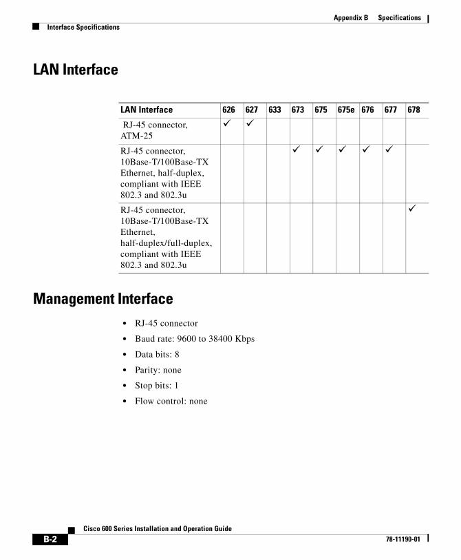
Appendix B SpecificationsInterface Specifications
LAN Interface
Management Interface• RJ-45 connector
• Baud rate: 9600 to 38400 Kbps
• Data bits: 8
• Parity: none
• Stop bits: 1
• Flow control: none
LAN Interface 626 627 633 673 675 675e 676 677 678
RJ-45 connector, ATM-25
! !
RJ-45 connector, 10Base-T/100Base-TX Ethernet, half-duplex, compliant with IEEE 802.3 and 802.3u
! ! ! ! !
RJ-45 connector, 10Base-T/100Base-TX Ethernet, half-duplex/full-duplex, compliant with IEEE 802.3 and 802.3u
!
B-2Cisco 600 Series Installation and Operation Guide
78-11190-01

Appendix B SpecificationsSoftware Upgrade
ADSL/SDSL Interface
Phone/Microfilter Interface (Cisco 675 and Cisco 678)• RJ-11 connector with built-in EZ-DSL microfilter (North American version
only) (Cisco 675)
• RJ-11 connector (Cisco 678)
Software Upgrade• Built-in Flash ROM
Power and Operating Requirements
Power Requirements
• 5 VDC @ 1.5 Amp
Operating Requirements
• Temperature: 32° to 104° F (0° to 40°C)
• Humidity: 5 to 90% (non-condensing)
RJ-11 Connector/Encoding 626 627 633 673 675 675e 676 677 678
DMT Issue 1 encoding ! !DMT Issue 2 encoding ! ! !SDSL, 2B1Q encoding ! !CAP encoding ! ! !G.Lite encoding ! ! !
B-3Cisco 600 Series Installation and Operation Guide
78-11190-01

Appendix B SpecificationsSDSL 2B1Q Transmission Specifications (Cisco 633 and Cisco 673)
SDSL 2B1Q Transmission Specifications (Cisco 633 and Cisco 673)
Table B-1 shows the SDSL 2B1Q transmission specifications for the Cisco 633 and Cisco 673.
CAP RADSL Transmission Specifications (Cisco 675, Cisco 675e and Cisco 678)
Table B-2 shows the CAP RADSL transmission specification.
Table B-1 SDSL 2B1Q Transmission Specifications
Specification Downstream Upstream
Maximum Transmit Power 13.5 dBm 13.5 dBm
Maximum Rate 1168 kbps 1168 kbps
Spectrum DC-2.92 MHz DC-2.92 MHz
Bandwidth 2.92 MHz 2.92 MHz
Table B-2 CAP RADSL Transmission Specifications
Specification Downstream Upstream
Maximum Transmit Power 22.7 dBm 13.3 dBm
Maximum Rate 7168 kbps 1088 kbps
Spectrum 240 – 1335KHz 35 – 191.4KHz
Bandwidth 1.095MHz 156KHz
B-4Cisco 600 Series Installation and Operation Guide
78-11190-01

Appendix B SpecificationsDMT Issue 1 Transmission Specifications (Cisco 676)
DMT Issue 1 Transmission Specifications (Cisco 676)
Table B-3 shows the DMT Issue 1 RADSL transmission specification.
DMT Issue 2 Transmission Specifications (Cisco 627, Cisco 677 and Cisco 678)
Table B-4 shows the DMT Issue 2 Rate Adaptive DSL transmission specification.
Table B-3 DMT Issue 1 Transmission Specifications
Specification Downstream Upstream
Maximum Transmit Power 20.4 dBm 12.5 dBm
Maximum Rate 9200 kbps 832 kbps
Spectrum 138-1104 KHz 26-138 KHz
Bandwidth 966 KHz 112 KHz
Table B-4 DMT Issue 2 Transmission Specifications
Specification Downstream Upstream
Maximum Transmit Power 20.4 dBm/Hz 12.5 dBm/Hz
Maximum Rate 8032 kbps 864 kbps
Spectrum 138-1104 KHz 26-138 KHz
Bandwidth 966 KHz 112 KHz
B-5Cisco 600 Series Installation and Operation Guide
78-11190-01

Appendix B SpecificationsDMT Issue 2 Transmission Specifications (Cisco 627, Cisco 677 and Cisco 678)
B-6Cisco 600 Series Installation and Operation Guide
78-11190-01

Cisco 600 Series78-11190-01
A
P P E N D I X C EZ-DSL Microfilter SpecificationsIntroduction
Note This appendix details the mechanical characteristics of the EZ-DSL microfilter, which is used only with the Cisco 627, Cisco 675, Cisco 675e, Cisco 676, Cisco 677 and Cisco 678 CPEs.
The EZ-DSL microfilters are used to connect telephones at the customer premises to the premises telephone wiring. The microfilters are designed to prevent interference between the router and the telephone set, and to reduce the effect of POTS-generated noise on the ADSL transceiver.
Note Use EZ-DSL Microfilters only at premises that do not have an ADSL POTS splitter installed.
Specifications The EZ-DSL microfilters exist in two forms: an in-line version and a wall-mount version. This section list the specifications for both.
C-1 Installation and Operation Guide

Appendix C EZ-DSL Microfilter SpecificationsSpecifications
In-Line MicrofilterThe in-line microfilters contain a plastic enclosure that houses a PCB assembly and RJ-11 female connector at either end. The top-level assembly includes a 3-inch RJ-11-to-RJ-11 pigtail for connection to the wall outlet. (See Figure C-1.)
Dimensions
• 2.50 x 1.00 x 1.03 inches
• 6.35 x 2.54 . x 2.6 cm
Figure C-1 In-Line Microfilter and Cable
Note The in-line microfilters do not work if connected improperly. To ensure that the microfilters work, connect the wall side of the microfilter to the wall jack and the phone side of the microfilter to the telephone.
Table C-1 In-Line Microfilter Pinouts
Pin Signal
3 Ring
4 Tip
1841
9
C-2Cisco 600 Series Installation and Operation Guide
78-11190-01

Appendix C EZ-DSL Microfilter SpecificationsSpecifications
Caution The in-line microfilters do not provide protection against transient noise for multi-line telephones, nor do they provide protection against power surges.
Installation Instructions
Step 1 Identify all home telephones plugged in and in service. An EZ-DSL microfilter should be installed at each home telephone.
Step 2 Unplug the telephone from the wall. Plug the telephone cord into the end of the EZ-DSL microfilter marked PHONE.
Step 3 Using the 3-inch telephone cord provided, plug one end of the cord into the microfilter marked WALL. Plug the other end of the cord into the telephone wall receptacle.
Step 4 After you have finished installation, verify that your telephone service works. If your telephone service does not work, disconnect the EZ-DSL Microfilter and contact your local telephone company or Cisco Systems.
Safety Precautions
Warning Take the telephone handset off the hook while wiring.
Warning Persons with pacemakers should never work with telephone wiring.
Wall-Mount MicrofilterThe wall-mount version is a plastic plate used in conjunction with wall-mount telephones. The wall-mount microfilter installs in the place of normal telephone jack outlets where the wall-mount telephones are used.
C-3Cisco 600 Series Installation and Operation Guide
78-11190-01

Appendix C EZ-DSL Microfilter SpecificationsSpecifications
Dimensions
• 4.50 x 2.75 inches
• 11.4 x 6.98 cm
Figure C-2 Wall Mount Microfilter
Installation Instructions
Step 1 Remove any existing wall mounts.
Step 2 Remove 3 inches from the outer jacket of telephone wire in the outlet box. Strip .75 inch from each individual conductor.
Step 3 Loosen screws on all jack terminals. Each terminal is color coded. Connect four wires to corresponding terminal screws. Check wiring.
Table C-2 Wall Mount Microfilter Pinouts
Pin Signal
3 Ring
4 Tip
1843
5
C-4Cisco 600 Series Installation and Operation Guide
78-11190-01

Appendix C EZ-DSL Microfilter SpecificationsRegulatory Approvals
Wire Code Installation Guide
Step 1 Remove front panel from supplied wall jack and attach jack to the outlet box with the screws provided. The word "Top" faces upward.
Step 2 To connect the telephone, align the plug on the telephone to the newly-installed wall jack. The rivet holes on the jack should line up with the rivet holes on the back of the telephone. Move the telephone downward to lock into place.
Step 3 Place the telephone handset back on the telephone.
Safety Precautions
Warning Take the telephone handset off the hook while wiring.
Warning Persons with pacemakers should never work with telephone wiring.
Regulatory Approvals• UL 1950, Third Edition
• FCC Part 68 (in-line microfilters only)
Table C-3 Jack Labeling and Wire Color Codes
Jack Labeling Wire Color Code 1 Wire Color Code 2
Red Red White with blue stripes
Green Green Blue with white stripes
Yellow Yellow White with orange stripes
Black Black Orange with white stripes
C-5Cisco 600 Series Installation and Operation Guide
78-11190-01

Appendix C EZ-DSL Microfilter SpecificationsRegulatory Approvals
C-6Cisco 600 Series Installation and Operation Guide
78-11190-01

Cisco 600 Ser78-11190-01
G L O S S A R Y
Numerics
2B1Q line encoding The 2B1Q (two binary, one quaternary) line encoding was intended for use by the ISDN DSL and SDSL. 2B1Q is a four-level line code that represents two binary bits (2B) as one quaternary symbol (1Q). ("Quaternary" means consisting of four, in this case, a four-level line code.) The 2B1Q line coding was seen as a major enhancement over the original T1 line coding, because 2B1Q encoded two bits instead of just one with every signaling state (baud).
A
address mask A bit mask used to select bits from an Internet address for subnet addressing. The mask is 32 bits long and selects the network portion of the Internet address and one or more bits of the local portion. Sometimes called subnet mask.
AAL5 ATM Adaptation Layer. This layer maps higher layer user data into ATM cells, making the data suitable for transport through the ATM network.
ADSL Asymmetric digital subscriber line. A digital subscriber line (DSL) technology in which the transmission of data from server to client is much faster than the transmission from the client to the server.
ATM Asynchronous Transfer Mode. A cell-based data transfer technique in which channel demand determines packet allocation. ATM offers fast packet technology, real time, demand led switching for efficient use of network resources.
authentication A security feature that allows access to information to be granted on an individual basis.
1ies Installation and Operation Guide

Glossary
auto-negotiation Procedure for adjusting line speeds and other communication parameters automatically between two computers during data transfer.
AWG American Wire Gauge. The measurement of thickness of a wire.
B
bandwidth The range of frequencies a transmission line or channel can carry: the greater the bandwidth, the greater the information-carrying capacity of a channel. For a digital channel this is defined in bits. For an analog channel it is dependent on the type and method of modulation used to encode the data.
bandwidth-on-dem
and
The ability of a user to dynamically set upstream and downstream line speeds to a particular speed.
bps Bits per second. A standard measurement of digital transmission speeds.
bridge A device that connects two or more physical networks and forwards packets between them. Bridges can usually be made to filter packets, that is, to forward only certain traffic. Related devices are: repeaters which simply forward electrical signals from one cable to the other, and full-fledged routers which make routing decisions based on several criteria. See repeater and router.
broadband Characteristic of any network that multiplexes independent network carriers onto a single cable. This is usually done using frequency division multiplexing (FDM). Broadband technology allows several networks to coexist on one single cable; traffic from one network does not interfere with traffic from another because the “conversations” happen on different frequencies in the “ether” rather like the commercial radio system.
Broadband Remote
Access Server
Device that terminates remote users at the corporate network or Internet users at the Internet service provider (ISP) network, that provides firewall, authentication, and routing services for remote users.
broadcast A packet delivery system where a copy of a given packet is given to all hosts attached to the network. Example: Ethernet.
A
2Cisco 600 Series Installation and Operation Guide
78-11190-01

Glossary
C
CAP encoding Carrierless Amplitude Phase signal modulation.
CO Central office. Refers to equipment located at a Telco or service provider’s office.
CPE Customer premises equipment. Refers to equipment located in a user's premises.
D
DMT Discrete Multi-Tone frequency signal modulation.
downstream rate The line rate for return messages or data transfers from the network machine to the user’s customer premises machine.
DRAM Dynamic Random Access Memory. A type of semiconductor memory in which the information is stored in capacitors on a metal oxide semiconductor integrated circuit.
DSLAM Digital Subscriber Line Access Multiplexer. Concentrates and multiplexes signals at the telephone service provider location to the broader wide area network.
E
encapsulation The technique used by layered protocols in which a layer adds header information to the protocol data unit (PDU) from the layer above. As an example, in Internet terminology, a packet would contain a header from the physical layer, followed by a header from the network layer (IP), followed by a header from the transport layer (TCP), followed by the application protocol data.
Ethernet One of the most common local area network (LAN) wiring schemes, Ethernet has a transmission rate of 10, 100, or 1000 Mbps.
3Cisco 600 Series Installation and Operation Guide
78-11190-01

Glossary
F
FCC Federal Communications Commission. A U.S. government agency that regulates interstate and foreign communications. The FCC sets rates for communication services,
FTP File Transfer Protocol. The Internet protocol (and program) used to transfer files between hosts.
H
hop count A measure of distance between two points on the Internet. It is equivalent to the number of gateways that separate the source and destination.
HTML Hypertext Markup Language. The page-coding language for the World Wide Web.
HTML browser A browser used to traverse the Internet, such as Netscape or Microsoft Internet Explorer.
http Hypertext Transfer Protocol. The protocol used to carry world-wide web (www) traffic between a www browser computer and the www server being accessed.
I
ICMP Internet Control Message Protocol. The protocol used to handle errors and control messages at the IP layer. ICMP is actually part of the IP protocol.
Internet address An IP address assigned in blocks of numbers to user organizations accessing the Internet. These addresses are established by the United States Department of Defense’s Network Information Center. Duplicate addresses can cause major problems on the network, but the NIC trusts organizations to use individual addresses responsibly. Each address is a 32-bit address in the form of x.x.x.x where x is an eight- bit number from 0 to 255. There are three classes: A, B and C, depending on how many computers on the site are likely to be connected.
4Cisco 600 Series Installation and Operation Guide
78-11190-01

Glossary
Internet A collection of networks interconnected by a set of routers which allow them to function as a single, large virtual network. When written in upper case, Internet refers specifically to the DARPA (Defense Advanced Research Projects Agency) Internet and the TCP/IP protocols it uses.
Internet Protocol
(IP)
The network layer protocol for the Internet protocol suite.
IP See Internet Protocol.
IP address The 32-bit address assigned to hosts that want to participate in a TCP/IP Internet.
IP datagram The fundamental unit of information passed across the Internet. It contains source and destination addresses along with data and a number of fields that define such things as the length of the datagram, the header checksum, and flags to say whether the datagram can be or has been fragmented.
ISO International Standards Organization. A voluntary, non-treaty organization founded in 1946, responsible for creating international standards in many areas, including computers and communications.
ISP Internet service provider. A company that allows home and corporate users to connect to the Internet.
ITU-T International Telecommunications Union, Standardization Sector. ITU-T is the telecommunication standardization sector of ITU and is responsible for making technical recommendations about telephone and data (including fax) communications systems for service providers and suppliers.
L
LAN Local area network. A limited distance (typically under a few kilometers or a couple of miles) high-speed network (typically 4 to 100 Mbps) that supports many computers.
LED Light emitting diode. The lights indicating status or activity on electronic equipment.
I
5Cisco 600 Series Installation and Operation Guide
78-11190-01

Glossary
line rate The speed by which data is transferred over a particular line type, expressed in bits per second (bps).
logical port A logical entry to a server machine. These ports are mostly invisible to the user, though you might occasionally see a URL with a port number included in it. These ports do not refer to physical locations; they are set up by server administrators for network trafficking.
loopback A diagnostic test that returns the transmitted signal back to the sending device after it has passed through a network or across a particular link. The returned signal can then be compared to the transmitted one. The discrepancy between the two helps to trace the fault. When trying to locate a faulty piece of equipment, loopbacks will be repeated, eliminating satisfactory machines until the problem is found.
M
MAC Media Access Control Layer. A sublayer of the Data Link Layer (Layer 2) of the ISO OSI Model responsible for media control.
MIB Management Information Base. A collection of objects that can be accessed via a network management protocol, such as SNMP and CMIP (Common Management Information Protocol).
modem pooling The ability of a service provider to dynamically switch users’ messages between modems, rather than requiring a modem to be dedicated to a particular user on a network.
multiplexer A device that can send several signals over a single line. The signals are then separated by a similar device at the other end of the link. This can be done in a variety of ways: time division multiplexing, frequency division multiplexing, and statistical multiplexing. Multiplexers are also becoming increasingly efficient in terms of data compression, error correction, transmission speed, and multi-drop capabilities.
L
6Cisco 600 Series Installation and Operation Guide
78-11190-01

Glossary
N
NAT Network Address Translation.
network layer The OSI layer that is responsible for routing, switching, and subnetwork access across the entire OSI environment.
node A general term used to refer to a computer or related device; often used to refer to a networked computer or device.
NVT Network Virtual Terminal.
NVRAM Non-Volatile Random Access Memory. The router uses this memory to store configuration information. The contents of this memory are not lost after a reboot or power cycle of the unit.
O
octet A networking term that identifies 8 bits. In TCP/IP, it is used instead of byte, because some systems have bytes that are not 8 bits.
OSI Open Systems Interconnection. An international standardization program to facilitate communications among computers from different manufacturers. See ISO.
P
packet The unit of data sent across a packet switching network.
PAP Password Authentication Protocol.
PCI Peripheral Component Interconnect. An industry local bus standard. Supports up to 16 physical slots but is electrically limited to typically three or four plug-in PCI cards in a PC. Has a typical sustained burst transfer rate of 80 Mbps, which is enough to handle 24-bit color at 30 frames per second (full-color, full-motion video).
7Cisco 600 Series Installation and Operation Guide
78-11190-01

Glossary
Permanent Virtual
Connection (PVC)
A fixed virtual circuit between two users: the public data network equivalent of a leased line. No call setup or clearing procedures are needed.
physical layer Handles transmission of raw bits over a communication channel. The physical layer deals with mechanical, electrical, and procedural interfaces.
physical port A physical connection to a computer through which data flows. An “Ethernet port,” for example, is where Ethernet network cabling plugs in to a computer.
port The abstraction used by Internet transport protocols to distinguish among multiple simultaneous connections to a single destination host. See selector.
POTS Plain Old Telephone Service. This is the term used to describe basic telephone service.
PPP Point-to-Point-Protocol. The successor to SLIP, PPP provides router-to-router and host-to-network connections over both synchronous and asynchronous circuits. See SLIP.
protocol A formal description of messages to be exchanged and rules to be followed for two or more systems to exchange information.
PVC See Permanent Virtual Connection.
R
RADIUS Remote Authentication Dial-In User Service (RADIUS). A client/server security protocol created by Livingston Enterprises. Security information is stored in a central location, known as the RADIUS server.
RADIUS
Accounting Client
Permits system administrators to track dial-in use.
RADIUS Security
Client
Controls access to specific services on the network.
P
8Cisco 600 Series Installation and Operation Guide
78-11190-01

Glossary
RADSL Rate Adaptive Digital Subscriber Line (RADSL). A technique for keeping the quality of transmissions within specified parameters.
remote address The IP address of a remote server.
remote server A network computer that allows a user to log on to the network from a distant location.
RFC Request for Comments. The document series, begun in 1969, which describes the Internet suite of protocols and related experiments. Not all RFCs describe Internet standards, but all Internet standards are written up as RFCs.
route The path that network traffic takes from its source to its destination. The route a datagram follows can include many gateways and many physical networks. In the Internet, each datagram is routed separately.
router A system responsible for making decisions about which of several paths network (or Internet) traffic will follow. To do this, it uses a routing protocol to gain information about the network and algorithms to choose the best route based on several criteria known as “routing metrics.” See bridge and repeater.
routing table Information stored within a router that contains network path and status information. It is used to select the most appropriate route to forward information along.
RS-232 An EIA standard that is the most common way of linking data devices together.
S
SDSL Symmetrical digital subscriber line. A digital subscriber line (DSL) technology in which the transmission of data from server to client is the same speed as the transmission from the client to the server.
secret Encryption key used by RADIUS to send authentication information over a network.
R
9Cisco 600 Series Installation and Operation Guide
78-11190-01

Glossary
serial line A serial line is used to refer to data transmission over a telephone line via a modem or when data goes from a computer to a printer or other device.
shared secret RADIUS uses the shared secret to encrypt the passwords in the authentication packets, so outside parties do not have access to the passwords on your network.
SNMP Simple Network Management Protocol. The network management protocol of choice for TCP/IP-based internets.
socket (1) The Berkeley UNIX mechanism for creating a virtual connection between processes. (2) IBM term for software interfaces that allow two UNIX application programs to talk via TCP/IP protocols.
Spanning-Tree
Bridge Protocol
(STP)
Spanning-Tree Bridge Protocol (STP). Part of an IEEE standard. A mechanism for detecting and preventing loops from occurring in a multi-bridged environment. When three or more LAN segments are connected by bridges, a loop can occur. Because a bridge forwards all packets which are not recognized as being local, some packets can circulate for long periods of time, eventually degrading system performance. This algorithm ensures only one path connects any pair of stations, selecting one bridge as the 'root' bridge, with the highest priority one as identifier, from which all paths should radiate.
spoofing A method of fooling network end stations into believing that keepalive signals have come from and returned to the host. Polls are received and returned locally at either end of the network and are transmitted only over the open network if there is a condition change.
STP See Spanning-Tree Bridge Protocol.
subnet For routing purposes, IP networks can be divided into logical subnets by using a subnet mask. Values below those of the mask are valid addresses on the subnet.
subnet mask See address mask.
synchronous
connection
During synchronous communications, data is not sent in individual bytes, but as frames of large data blocks.
SYSLOG SYSLOG allows you to log significant system information to a remote server.
S
10Cisco 600 Series Installation and Operation Guide
78-11190-01

Glossary
T
TCP Transmission Control Protocol. The major transport protocol in the Internet suite of protocols providing reliable, connection-oriented full-duplex streams.
TFTP Trivial File Transfer Protocol. A simple file transfer protocol (a simplified version of FTP) that is often used to boot diskless workstations and other network devices such as routers over a network (typically a LAN). Has no password security.
Telnet The virtual terminal protocol in the Internet suite of protocols. Allows users of one host to log into a remote host and act as normal terminal users of that host.
training mode Characteristic of a router that allows it to use RADSL technology to adjust its line speed according to noise conditions on the transmission line.
transparent
bridging
So named because the intelligence necessary to make relaying decisions exists in the bridge itself and is thus transparent to the communicating workstations. It involves frame forwarding, learning workstation addresses and ensuring no topology loops exist (in conjunction with the Spanning-Tree algorithm).
Trivial File Transfer
Protocol
See TFTP.
twisted pair Two insulated copper wires twisted together with the twists or lays varied in length to reduce potential signal interference between the pairs.
11Cisco 600 Series Installation and Operation Guide
78-11190-01

Glossary
U
UDP User Datagram Protocol. A connectionless transport protocol that runs on top of TCP/IP’s IP. UDP, like TCP, uses IP for delivery; however, unlike TCP, UDP provides for exchange of datagrams without acknowledgments or guaranteed delivery. Best suited for small, independent requests, such as requesting a MIB value from an SNMP agent, in which first setting up a connection would take more time than sending the data.
UL Underwriters Laboratories. A private organization that tests and certifies electrical components and devices against rigorous safety standards. A UL Listing Mark on a product means that representative samples of the product have been tested and evaluated to nationally recognized safety standards with regard to fire, electric shock, and other related safety hazards.
UNI signaling User Network Interface signaling for ATM communications.
upstream rate The line rate for message or data transfer from the source machine to a destination machine on the network. Also see downstream rate.
V
VC See Virtual Connection.
Virtual Connection
(VC)
A link that seems and behaves like a dedicated point-to-point line or a system that delivers packets in sequence, as happens on an actual point-to-point network. In reality, the data is delivered across a network via the most appropriate route. The sending and receiving devices do not have to be aware of the options and the route is chosen only when a message is sent. There is no pre-arrangement, so each virtual connection exists only for the duration of that one transmission.
VIP Virtual Ethernet Interface.
12Cisco 600 Series Installation and Operation Guide
78-11190-01

Glossary
W
WAN Wide area network. A data communications network that spans any distance and is usually provided by a public carrier (such as a telephone company or service provider).
13Cisco 600 Series Installation and Operation Guide
78-11190-01

Glossary
14Cisco 600 Series Installation and Operation Guide
78-11190-01

Cisco 600 Ser78-11190-01
I N D E X
A
add a route 5-16
address ranges
VPI/VCI 5-13
ADSL performance 5-49
ADSL port
connector
pinouts A-9
ambient temperature
operational 1-7
storage 1-7
archives
backup, using tftp 5-28
asymmetric digital subscriber line
See ADSL
Asynchronous Transfer Mode
See ATM
ATM
circuits
setting up 3-3, 3-5, 5-13
virtual connections
setting up 3-3, 5-12
ATM25 2-2
ATM25 interface 1-4
ATM connections
two types 5-12
Attenuation field 3-21
B
BCP 1-5, 1-6, 5-5, 5-7
bridge mode 5-5, 5-7
bridging control protocol
See BCP
C
cabling
Management port 2-4
CAP 1-4, 5-3
downstream/upstream rates 5-12
CAP RADSL
transmission
specifications
table of B-4Carrierless Amplitude Modulation and Phase
(CAP) 1-4
CBOS
commands
1ies Installation and Operation Guide

Index
stats 3-21
logging on to 4-2, 5-3
login screen 4-2, 5-3
log on to 3-2
operation modes 3-2
prompt 5-46
changes to NVRAM 4-3, 5-4
changing passwords 5-47
changing VCI settings 5-14
changing VPI settings 5-13
channel support 1-6
Cisco Broadband Operating System
See CBOS
clients
RADIUS 5-20
command line interface 5-24
configuration
checklist for 2-1, 5-1
configuration checklist 3-1
configuration file
changes to
saving 3-21, 5-49
configurationless provisioning
changing 5-10
disable 5-9
enable 5-8
configuration procedures 5-1
configure the Ethernet port 5-11
configuring RADIUS 5-21
connection modes 5-5
contents of your carton 2-2
Corrected/Uncorrected Blocks field 3-21
CRC Errors field 3-21, 5-49
creating routing tables 5-16
D
DHCP client 5-18
DHCP server 5-19
disable
in-band bridging management VC 5-7
RFC1483 5-7
display statistics 5-49
DMT Issue 2 5-4, 7-4
downstream/upstream rates 5-12
transmission specifications B-5
DMT Issue 2 encoding B-3
DMT Issue Transmission Specifications B-5
DMT RADSL transmission specifications
table of B-5
DMT transmission specifications
table of B-4
document objectives xvii
DRAM 1-7
2Cisco 600 Series Installation and Operation Guide
78-11190-01

Index
E
enable
in-band bridging management VC 5-6
RFC1483 5-6
enable IP filtering 5-17
enable mode 3-2
enable NAT 5-20
Enable Routing Information Protocol (RIP) 5-17
Errored Seconds field 3-21
Ethernet Address Resolution Protocol (RFC 826) 1-6
Ethernet connector A-5
pinouts A-5
Ethernet port A-5
configure 5-11
configuring 5-47
connector
illustration of A-5
pinouts A-5
exec and enable 4-3, 5-4
exec mode 3-2
exec user password 5-27
F
filtering 5-17
G
G.Lite 1-4, 5-4, 7-6, B-3
downstream/upstream rates 5-12
general applications supported by 1-7
H
hardware features 1-3
list of 1-3
I
idle timeout 5-30
installation
checklist for 2-1
installing 2-1
Internet Control Message Protocol (RFC 792) 1-6
Internet Protocol (RFC 791) 1-5
interpret statistics 5-49
invalid cell counter 5-50
IP address
assigning 3-19, 4-8, 5-47
updating 7-3
IP filtering
enable 5-17
3Cisco 600 Series Installation and Operation Guide
78-11190-01

Index
L
LAN interface A-5
LED status lights
checking 5-48
Linux
term and termcap 5-26, 7-3
logon to CBOS 4-2, 5-3
M
management applications 5-18
management applications, network 1-7
Management port
cabling
illustration of 2-4
connecting to 2-4
pinouts A-7
management VCs, configuring the 3-3
memory
default configuration 1-7
expanded
options for 1-7
modes, exec and enable 3-2
N
NAT 5-20
enable 5-20
netmask address
assigning 5-11
network management applications 1-7
O
OAM-F5 loopback cell 3-22, 5-49
objectives, document xvii
operating environment
ambient temperature of 1-7
Operation, Administration, Maintenance (OAM) Loopback Cells field 3-22, 5-49
operational modes 4-3, 5-4
operation modes 3-2
overflow
serial buffer 7-2
P
password
avoiding a bad 3-19, 4-8
changing 3-19, 4-8
passwords
examples 5-47
Phone port
connector
pinouts A-10
physical layer 1-5
physical specifications
4Cisco 600 Series Installation and Operation Guide
78-11190-01

Index
weight B-1
Point-to-Point Protocol
See PPP
ports
ENET A-3
MGMT A-3
PHONE A-3
WALL A-3
POTS splitter 2-6, 2-9
Power LED 2-19
condition indicator 7-2
PPP 1-5, 1-6, 5-5, 5-7
login and password 5-21
PPP routing 5-8
preferences
Telnet 5-26
terminal 5-26
Previous SNR Margin field 3-22
procedures, configuration 3-1
product features
ATM cell delineation 1-4
permanent virtual circuits 1-4
status LEDs 1-4
PVCs 1-4
R
RADIUS 1-6
client 5-20
using 5-20
RADIUS client
Cisco 677 implementation 5-21
RADIUS passwords
setting length of 7-3
rear panel cable connections 2-17
Remote Authentication Dial-In User Service
See RADIUS
required hardware 2-3
RFC 1483 routing 5-10
RFC 2058 1-6
RFC 2059 1-6
RIP 5-17
enable 5-17
RIP traffic 7-3
RJ-11 connector A-9, A-10
RJ-45 connector A-5
routing mode 5-8
routing protocols, supported 1-5
routing tables
creating 5-16
Rx’ed Blocks field 3-21
5Cisco 600 Series Installation and Operation Guide
78-11190-01

Index
S
SDSL 2B1Q transmission specifications B-4
security and accounting 1-6
serial buffer overflow 7-2
serial port
configuring 2-5
session timeout 5-30
set a default route 5-16
set a destination address 5-17
set dhcp client command 5-19
set dhcp server command 5-19
set filter command 5-17
set interface command 5-11, 5-13
set interface wan0 7-4
set nat enabled command 5-20
set password command 5-47
set PPP
login 5-21
password 5-21
set radius test command 5-22
set syslog test command 5-23
set timeout command 5-30
set your COM protocol 2-5
show interface wan0 command 7-7
Signal-to-Noise (SNR) Margin field 3-22
software features 1-5
list of 1-5
software image
transfer, using TFTP 5-28
software updates 5-28
specifications
ADSL Interface B-3
LAN Interface B-2
Management Interface B-2
Operating Requirements B-3
Phone/Microfilter Interface B-3
Power Requirements B-3
Regulatory Approvals B-5
specify
a gateway 5-16
a netmask 5-16
standard contents 2-2
standards
100BaseTX 1-5
802.3u 10BaseT 1-5
ANSI T1.413 Issue 1 1-5
ATM Forum UNI Version 3.1 PVC 1-5
G.992.2 1-5
IEEE 802.1d 1-5
IEEE 802.3 1-5
IETF RFC 1483 encapsulation AAL5 1-5, 1-6
RFC 1638 - BC 1-5
statistics
interpreting 3-21, 5-49
statistics definitions 3-21
stats command 5-49
output 3-21
6Cisco 600 Series Installation and Operation Guide
78-11190-01

Index
stats wan0-0 command 5-50
stats wan0 command 5-49
SYSLOG
configuration file entry 5-23
implementing 5-23
logs 5-23
messages 5-23
server 5-23
using 5-24
SYSLOG client 5-23
T
tasks to be completed 2-1
Telnet 5-24
halting timeouts 5-27
using 5-24
Telnet, using 3-6
telnet daemon 5-25
Telnet preferences 5-26
terminal preferences 5-26
TFTP 5-27
backups 5-28
software updates 5-28
using 3-10, 5-27
using with UNIX 5-28
using with WIN95/98 5-29
using with WINNT 5-29
TFTP server 5-27
third-party products
Linux 2.0.27 5-24
NTSyslog 5-24
Solaris 2.5 5-24
timeout values
session and idle 5-30
troubleshooting
ADSL line 7-5
ADSL parameters 7-4
ATM cell delineation 7-6
ATM cell scrambling 7-6
IDLE timeout 7-7
incompatible configuration 7-6
incompatible user/password configuration 7-7
incorrect RADIUS server IP address 7-7
IP addresses, updating of 7-3
line noise 7-5
Linux term and termcap 7-3
MAC address 7-3
near-end DMT firmware incompatible with far-end DMT firmware 7-6
POWER LED 7-2
power off, Cisco 7200 7-6
RADIUS passwords 7-3
serial buffer overflow 7-2
SESSION timeout 7-7
subscriber 7-5
VPI/VCI mapping 7-6
VPI/VCI provisioning 7-6
7Cisco 600 Series Installation and Operation Guide
78-11190-01
Index
Tx’ed Blocks field 3-21
U
UNIX
connecting from 5-27
unpacking
checklist for 2-2
updating IP addresses 7-3
updating your software 5-28
User Datagram Protocol (RFC 768) 1-5
V
VCI
defining 3-3, 3-5, 5-13, 5-14
VCI settings
changing 5-14
virtual circuit identifier (VCI) 5-12
virtual connections
setting up 3-3, 5-12
virtual path identifier
See VPI
virtual WAN connections 5-12
VPI
defining 3-3, 3-5, 5-13, 5-14
VPI/VCI 5-5
address ranges 5-13
VPI settings
changing 5-13
W
WAN port
configuring 5-12
WAN ports
physical and logical 5-12
Windows
network virtual terminal 5-25, 5-26
WIN95/98, connecting from 5-25
WIN95/98 users 5-24
WINNT, connecting from 5-25
WINNT users 5-24
write command 5-48
8Cisco 600 Series Installation and Operation Guide
78-11190-01