Embed Size (px)
Citation preview
CIS Lighting Standard
The University of Sydney
Engineering & Sustainability Team

CAMPUS INFRASTRUCTURE & SERVICES
CIS Lighting Standard - Final CIS-PLA-STD-Lighting 002 Date of Issue: 18 September 2015 ii
Document Control
Document Name: CIS Lighting Standard
Document ID: CIS-PLA-STD-Lighting
Document Status: Final
Version No: 002
Author(s): David Clarke
Position: Services Engineer - Electrical
Signature:
Document Owner:
Engineering & Sustainability Team
Approved by:
Position: Director of CIS
Signature:
Date Approved: 18 September 2015
Date of Issue: 18 September 2015
Issued by: Campus Infrastructure & Services

CAMPUS INFRASTRUCTURE & SERVICES
CIS Lighting Standard - Final CIS-PLA-STD-Lighting 002 Date of Issue: 18 September 2015 iii
Contents
1 PURPOSE ..................................................................................................... 1
2 SCOPE ......................................................................................................... 1
3 GLOSSARY OF TERMS ................................................................................. 2
4 AUTHORITIES & RESPONSIBILITIES ............................................................. 3
5 LUMINAIRE TECHNICAL REQUIREMENTS ................................................... 3
5.1 GENERAL .............................................................................................................................................................. 3
5.1.1 GENERAL REQUIREMENTS FOR LUMINAIRE PRODUCTS AND EQUIPMENT .............................................. 3 5.1.2 LUMINAIRE AND LAMP REQUIREMENTS ................................................................................................. 4 5.1.3 THE DEEMED-TO-COMPLY LIGHTING APPROVAL PROCESS ................................................................. 5 5.1.4 CORRELATED COLOUR TEMPERATURE (CCT) ........................................................................................ 5 5.1.5 FLUORESCENT LAMP BALLASTS AND LED CONTROL GEARS ................................................................ 6 5.1.6 PHOTOMETRIC, THERMAL AND ENERGY DATA ..................................................................................... 7
5.2 INTERNAL ............................................................................................................................................................. 7
5.2.1 LUMINAIRE DESIGN AND SELECTION ..................................................................................................... 7 5.2.2 LUMINAIRE SELECTION FOR UNIVERSITY SPACES .................................................................................. 8 5.2.3 GENERAL LUMINAIRE CONSTRUCTION .............................................................................................. 11 5.2.4 DOWNLIGHT CONSTRUCTION .......................................................................................................... 11 5.2.5 ADDITIONAL EQUIPMENT ................................................................................................................... 11
5.3 EXTERNAL .......................................................................................................................................................... 12
5.3.1 GENERAL REQUIREMENTS................................................................................................................... 12 5.3.2 EXTERIOR LIGHT POLES, FIXINGS AND WIRING ................................................................................ 12
5.4 CUSTOMISED LUMINAIRES ............................................................................................................................ 13
5.5 REDUNDANT EQUIPMENT ............................................................................................................................. 13
6 LIGHTING SYSTEM DESIGN ....................................................................... 13
6.1 STANDARDS AND CODES ............................................................................................................................. 13
6.2 DESIGN PARAMETERS .................................................................................................................................... 14
6.2.1 COMPUTERISED LIGHT MODELLING ................................................................................................... 14 6.2.2 WHOLE OF LIFE COST AND PERFORMANCE CONSIDERATIONS ........................................................ 15

CAMPUS INFRASTRUCTURE & SERVICES
CIS Lighting Standard - Final CIS-PLA-STD-Lighting 002 Date of Issue: 18 September 2015 iv
6.3 DESIGN SOFTWARE ....................................................................................................................................... 15
6.4 LUMINAIRES AND ILLUMINANCE LEVEL REQUIREMENTS ........................................................................ 15
7 LIGHTING CONTROL SYSTEMS ................................................................. 18
7.1 GENERAL REQUIREMENTS ............................................................................................................................. 18
7.2 LIGHTING CONTROLS IN UNIVERSITY TEACHING AREAS AND OFFICES.......................................... 19
7.3 LIGHTING CONTROL STRATEGIES .............................................................................................................. 19
7.4 LIGHTING CONTROL METHODOLOGY ..................................................................................................... 22
7.5 LIGHTING SYSTEMS AND LIGHTING CONTROL SYSTEMS REQUIREMENTS ..................................... 26
7.5.1 AUDITORIUMS AND LECTURE THEATRES (WITH VIDEO PROJECTORS) ................................................ 26 7.5.2 SEMINAR ROOMS AND LEARNING STUDIOS (FLAT FLOOR WITH VIDEO PROJECTORS) .................... 28 7.5.3 COMPUTER TEACHING LABORATORIES AND TEACHING LABORATORIES ........................................... 30 7.5.4 INDIVIDUAL OFFICES .......................................................................................................................... 31 7.5.5 OPEN OFFICES AND HDR DESKS ...................................................................................................... 32 7.5.6 PLANT, COMMUNICATIONS AND ELECTRICAL SWITCH ROOMS ........................................................ 32 7.5.7 FOR LARGE AREAS / ROOMS, ........................................................................................................... 33 7.5.8 STORE AND CLEANERS ROOMS ......................................................................................................... 33 7.5.9 CIRCULATION SPACES, STUDENT COMMONS AND AMENITIES ......................................................... 33
7.6 LIGHTING CONTROL SYSTEMS (LCS) ......................................................................................................... 33
7.6.1 LIGHTING CONTROL ......................................................................................................................... 34 7.6.2 SWITCHES ......................................................................................................................................... 35 7.6.3 OCCUPANCY SENSORS ..................................................................................................................... 35 7.6.4 USE OF DAYLIGHT SENSORS ............................................................................................................. 37 7.6.5 EXTERIOR LIGHTING CONTROL.......................................................................................................... 37 7.6.6 STAIRWELL LIGHTING CONTROL ....................................................................................................... 37 7.6.7 BUILDING CAR PARKING AREA LIGHTING CONTROL ........................................................................ 38
7.7 CENTRAL LIGHTING CONTROL SYSTEMS (CLCS) .................................................................................... 38
7.7.1 LIGHTING CONTROL SYSTEM CONFIGURATION ................................................................................ 38 7.7.2 LIGHTING CONTROL SYSTEMS HARDWARE INSTALLATION ................................................................ 39 7.7.3 LIGHTING CONTROL SYSTEMS SOFTWARE INSTALLATION ................................................................. 39 7.7.4 LIGHTING CONTROL SYSTEMS DOCUMENTATION ............................................................................. 39
8 EMERGENCY AND EXIT LIGHTING ........................................................... 40
8.1 EMERGENCY LIGHTING ................................................................................................................................. 40
8.1.1 GENERAL ........................................................................................................................................... 40 8.1.2 LIGHT FITTINGS ................................................................................................................................. 40 8.1.3 DISCHARGE TEST SWITCHES .............................................................................................................. 40 8.1.4 COMPUTERISED MONITORING AND TESTING SYSTEMS .................................................................... 41

CAMPUS INFRASTRUCTURE & SERVICES
CIS Lighting Standard - Final CIS-PLA-STD-Lighting 002 Date of Issue: 18 September 2015 v
9 SHOP DRAWINGS ..................................................................................... 41
10 SAFETY IN DESIGN .................................................................................... 41
11 COMMISSIONING ..................................................................................... 42
12 DOCUMENTATION & RECORDS ............................................................... 42
13 OPERATIONS ............................................................................................ 43
14 AUTHORISATION OF VARIATIONS .......................................................... 43
15 QUALITY CONTROL .................................................................................. 44
15.1 DESIGN STANDARD COMPLIANCE ............................................................................................................. 44
15.2 DESIGN STANDARD CERTIFICATION .......................................................................................................... 44
16 REFERENCES .............................................................................................. 45
17 DOCUMENT AMENDMENT HISTORY ........................................................ 47
18 ATTACHMENTS ......................................................................................... 47

CIS Lighting Standard - Final CIS-PLA-STD-Lighting 002 Date of Issue: 18 September 2015 1
1 PURPOSE
The CIS Lighting Standard sets out the University of Sydney's minimum requirements for the design, construction and maintenance of interior and exterior lighting systems. It ensures new and refurbished lighting systems are energy efficient, fit-for-purpose, made from durable good-quality materials, contain no or minimal environmentally harmful substances, and are cost efficient to operate and maintain. Applicable requirements documented in Workplace Health and Safety legislation, Disability Discrimination legislation, State Environmental Planning legislation, Commonwealth and State legislation, National Construction Codes (NCC), and Australian and New Zealand Standards (AS/NZS) are the minimum and mandatory compliance requirements. Where any ambiguity exists between this standard and the aforementioned mandatory requirements then:
a. the highest performance requirements must apply;
b. applicable requirements must follow this order of precedence:
i. Workplace Health and Safety legislation; ii. Disability Discrimination legislation; iii. State Environmental Planning and Assessment legislation; iv. All other Commonwealth and State legislation; v. NCC; vi. AS/NZS; vii. This standard and other University standards.
2 SCOPE
This standard describes minimum requirements for design, purchase, construction, and operation and maintenance of internal and external lighting systems for buildings and spaces owned, operated, maintained and/or managed by the University of Sydney. It applies to:
a. new building construction;
b. refurbishment projects for University-owned spaces over 50m2 excluding external walls;
c. refurbishments of spaces that form part of a broader medium-term (less than five years)
programme/plan of progressive upgrades to a University-owned building;
d. refurbishment projects for long-term University-leased (more than five years post-
refurbishment) spaces over 50m2 excluding external walls;
e. facilities maintenance services.
The standard covers most University-specific space types and applications. Where specific applications are not explicitly covered or ambiguity exists, the intent of the design standard must be satisfied. In such cases a return design brief must be provided for review and approval by the issuer of this standard or their appointed delegate who must have relevant technical competence in the subject matter. The standard applies to planners, project managers, consultants, contractors, sub-contractors, tenants, managing agents, University staff and others involved in the design, construction, installation, operation and maintenance of existing, new and proposed University buildings and facilities.
CAMPUS INFRASTRUCTURE & SERVICES
CIS Lighting Standard - Final CIS-PLA-STD-Lighting 002 Date of Issue: 18 September 2015 2
Lighting products and services provided or specified by designers, consultants, staff and contractors must conform to this standard.
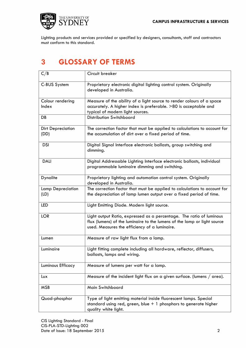
3 GLOSSARY OF TERMS
C/B Circuit breaker
C-BUS System Proprietary electronic digital lighting control system. Originally developed in Australia.
Colour rendering Index
Measure of the ability of a light source to render colours of a space accurately. A higher index is preferable. >80 is acceptable and typical of modern light sources.
DB Distribution Switchboard
Dirt Depreciation (DD)
The correction factor that must be applied to calculations to account for the accumulation of dirt over a fixed period of time.
DSI Digital Signal Interface electronic ballasts, group switching and dimming.
DALI Digital Addressable Lighting Interface electronic ballasts, individual programmable luminaire dimming and switching.
Dynalite Proprietary lighting and automation control system. Originally developed in Australia.
Lamp Depreciation (LD)
The correction factor that must be applied to calculations to account for the depreciation of lamp lumen output over a fixed period of time.
LED Light Emitting Diode. Modern light source.
LOR Light output Ratio, expressed as a percentage. The ratio of luminous flux (lumens) of the luminaire to the lumens of the lamp or light source used. Measures the efficiency of a luminaire.
Lumen Measure of raw light flux from a lamp.
Luminaire Light fitting complete including all hardware, reflector, diffusers, ballasts, lamps and wiring.
Luminous Efficacy Measure of lumens per watt for a lamp.
Lux Measure of the incident light flux on a given surface. (lumens / area).
MSB Main Switchboard
Quad-phosphor
Type of light emitting material inside fluorescent lamps. Special standard using red, green, blue + 1 phosphors to generate higher quality white light.

CAMPUS INFRASTRUCTURE & SERVICES
CIS Lighting Standard - Final CIS-PLA-STD-Lighting 002 Date of Issue: 18 September 2015 3
RCD Residual Current Device (Earth leakage protection)
T5 16mm diameter linear fluorescent lamp. Commonly used for general, classroom and office interior spaces.
T8 26mm diameter linear fluorescent lamp. Older standard but still acceptable in some areas.
Tri-phosphor Type of light emitting material inside fluorescent lamps. Current standard uses red, green and blue phosphors to generate white light.
4 AUTHORITIES & RESPONSIBILITIES
The design standard is issued by CIS. It is approved and signed-off by the Director CIS and the Engineering & Sustainability Unit is responsible for reviewing and maintaining the standard and keeping it up-to-date. The standard must be reviewed and kept up-to-date at least biennially.
5 LUMINAIRE TECHNICAL REQUIREMENTS
Details of design and construction requirements for lighting systems are outlined in this section.
5.1 GENERAL
5.1.1 GENERAL REQUIREMENTS FOR LUMINAIRE PRODUCTS AND EQUIPMENT
Lighting within The University of Sydney should provide the appropriate amount of functional illumination for the task, be energy efficient and provide aesthetic appeal to the building. Artificial lighting must satisfy the statutory requirement for safety. The selected lighting system must satisfy the current minimum energy efficiency performance requirements of the NCC Section J. The University of Sydney (UoS) is committed to maintaining a sustainable environment across all our campuses, where we can deliver world-class teaching, learning and research while minimising our ecological footprint. The Lighting Designers involve in UoS projects must give precedence to fit-for-purpose, lamp quality, lighting energy efficiency, cost effectiveness, good quality construction, safe serviceability and maintenance over aesthetic considerations. The designer must select and install good quality and energy efficiency luminaire that does not incur high project capital, low energy consumption, high quality of lighting output, long lamp life, easy in installation and low maintenance costs. Good lighting design and selection of the artificial lighting system should consider and implement the Life Cycle Costing principles. All lighting system products and equipment must:
a. comply with AS/NZS and have relevant current compliance certifications to quality
management systems, standards and codes;
b. be readily available on-demand and in large volumes in the local market from a wide range
of reputable long-standing local suppliers;
c. be readily serviceable by a wide range of electrical contractors;

CAMPUS INFRASTRUCTURE & SERVICES
CIS Lighting Standard - Final CIS-PLA-STD-Lighting 002 Date of Issue: 18 September 2015 4
d. be supported by large quantities of locally available critical spare parts that can be
delivered to the University on demand;
e. demonstrate proven local track record of performance and longevity in comparable
applications;
f. be made from durable good-quality materials;
g. contain no, or minimal, environmentally harmful substances e.g. hazardous materials and
chemicals;
h. be cost efficient to operate and maintain.
All luminaires are to meet with the following parameters:
i. each luminaire is corrected to a minimum power factor of 0.90 lagging;
j. installations must conform to IEC 61547 for minimum radio interference;
k. appropriate levels of visual comfort and use of low glare diffusers and systems in areas such
as terraced lecture theatres, etc.;
l. resistance to dirt built up and use of luminaires with appropriate IP ratings;
m. use of ‗plug and play‘ luminaires method wherever possible.
5.1.2 LUMINAIRE AND LAMP REQUIREMENTS
The light fittings selected by and deemed-to-comply with the requirements of The UoS are based upon their Life Cycle Costing, energy efficiency as well as ease of installation and low maintenance. The deemed-to-comply lighting should provide standardised appearance and harmonise with existing lighting installation. The University is aiming to minimise the number of spare parts from various manufacturers for routine maintenance. For the sake of standardisation of the equipment and spare parts, University has special preferences in relation to the type of energy efficient lamps, wattage and its application. The deemed-to-comply light fittings must be utilised for new and refurbishment projects that are managed by University Campus Infrastructure and Services (CIS). Approved LED and T5 fluorescent luminaires must be used for all University projects. Existing luminaires utilising incandescent, dichroic and tungsten halogen lamps are to be replaced by energy efficient luminaires in all University projects. Each luminaire must use constant current LED drivers or high frequency (HF) electronic ballast to achieve power factor greater than 0.90 lagging. The LED drivers or fluorescent HF electronic ballasts used are to be as recommended by the luminaire manufacturers. A wide range of most frequently used luminaires can be found on the Deemed-to-Comply Luminaire Schedule Form (CIS-ENG-F006) which can be downloaded from the Form section on the web site. Should the architect(s) and/or lighting designer(s) wish to utilise alternative luminaires to achieve desired illumination effect, written approval must be obtained from University CIS Electrical Services Engineer prior to issuing for tendering. Refer to clause 5.1.3 for CIS lighting approval process. Luminaire designers and specifier's must give precedence to:
a. fitness-for-purpose;
b. durability and good quality construction;
c. lamp quality and energy efficiency;
d. local manufacturers and availability;
e. cost effective and safe serviceability and maintenance; over
f. aesthetic considerations that incur high capital, operational and maintenance costs.

CAMPUS INFRASTRUCTURE & SERVICES
CIS Lighting Standard - Final CIS-PLA-STD-Lighting 002 Date of Issue: 18 September 2015 5
5.1.3 THE DEEMED-TO-COMPLY LIGHTING APPROVAL PROCESS
The following is CIS Deemed-to-Comply lighting approval process. The designer must submit technical details and information about the proposed luminaire to the CIS Electrical Services Engineer for approval, including but not limited to the following;
a. manufacturer‘s data sheet/ catalogue;
b. luminaire compliance certificates;
c. test reports;
d. luminaire photometric ( IES electronic files);
e. warranty;
f. luminaire construction;
g. physical dimensions;
h. mounting details;
i. control gear;
j. DALI control capability;
k. type of lamp and wattage;
l. luminaire light output ratio;
m. efficacy;
n. LED lamp future replacement arrangement;
o. EMC compliance;
p. unit price;
q. country of origin;
r. delivery lead time and images of the luminaire.
The CIS Electrical Services Engineer is to use the submitted information to assess whether the proposed luminaire meets the minimum lighting performance, construction quality and pricing requirements. CIS will require the suppliers to provide a sample of the proposed luminaire for review. After written approval had been granted, Lamp design and selection process must take into consideration the following:
a. long lamp life, low replacement and maintenance cost;
b. use the University‘s preferred lamp types and limit the number of different lamp types used in
a project;
c. consider risk of colour shift, instability and premature failure;
d. thoroughly scrutinise new and emerging technology and to check for risks of instability; and
e. adopt LED luminaires that have a demonstrated and proven stability, durability and
illumination performance in comparable applications.
Alternative lamp products must be accepted based on evaluation of demonstrated and proven performance to the requirements of this standard.
5.1.4 CORRELATED COLOUR TEMPERATURE (CCT)
All lamp correlated colour temperatures (CCT) must be reviewed and approved by the CIS Planning team‘s architects and interior designers. The following colour temperatures apply:
a. 4000K for internal workplaces with predominantly white walls e.g. offices, computer labs and
laboratories;
b. 2700K to 3000K for:
i. Heritage building interiors;
CAMPUS INFRASTRUCTURE & SERVICES
CIS Lighting Standard - Final CIS-PLA-STD-Lighting 002 Date of Issue: 18 September 2015 6
ii. Exterior lighting of sandstone facades and walls; iii. Passive recreational, dining, breakout spaces and theatres; iv. Residential; v. Where required due to interior finishes.
The University‘s current deemed-to-comply luminaires are provided in a schedule for reference for designers and contractors.
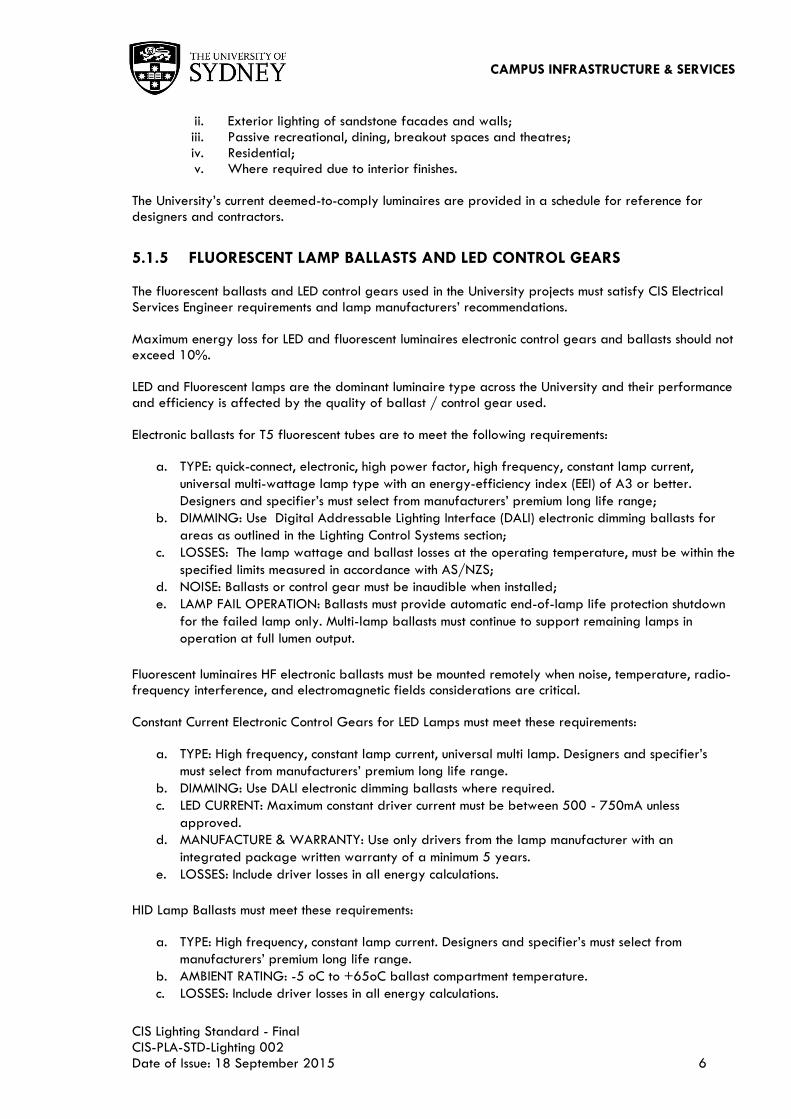
5.1.5 FLUORESCENT LAMP BALLASTS AND LED CONTROL GEARS
The fluorescent ballasts and LED control gears used in the University projects must satisfy CIS Electrical Services Engineer requirements and lamp manufacturers‘ recommendations. Maximum energy loss for LED and fluorescent luminaires electronic control gears and ballasts should not exceed 10%. LED and Fluorescent lamps are the dominant luminaire type across the University and their performance and efficiency is affected by the quality of ballast / control gear used. Electronic ballasts for T5 fluorescent tubes are to meet the following requirements:
a. TYPE: quick-connect, electronic, high power factor, high frequency, constant lamp current,
universal multi-wattage lamp type with an energy-efficiency index (EEI) of A3 or better.
Designers and specifier‘s must select from manufacturers‘ premium long life range;
b. DIMMING: Use Digital Addressable Lighting Interface (DALI) electronic dimming ballasts for
areas as outlined in the Lighting Control Systems section;
c. LOSSES: The lamp wattage and ballast losses at the operating temperature, must be within the
specified limits measured in accordance with AS/NZS;
d. NOISE: Ballasts or control gear must be inaudible when installed;
e. LAMP FAIL OPERATION: Ballasts must provide automatic end-of-lamp life protection shutdown
for the failed lamp only. Multi-lamp ballasts must continue to support remaining lamps in
operation at full lumen output.
Fluorescent luminaires HF electronic ballasts must be mounted remotely when noise, temperature, radio-frequency interference, and electromagnetic fields considerations are critical. Constant Current Electronic Control Gears for LED Lamps must meet these requirements:
a. TYPE: High frequency, constant lamp current, universal multi lamp. Designers and specifier‘s
must select from manufacturers‘ premium long life range.
b. DIMMING: Use DALI electronic dimming ballasts where required.
c. LED CURRENT: Maximum constant driver current must be between 500 - 750mA unless
approved.
d. MANUFACTURE & WARRANTY: Use only drivers from the lamp manufacturer with an
integrated package written warranty of a minimum 5 years.
e. LOSSES: Include driver losses in all energy calculations.
HID Lamp Ballasts must meet these requirements:
a. TYPE: High frequency, constant lamp current. Designers and specifier‘s must select from
manufacturers‘ premium long life range.
b. AMBIENT RATING: -5 oC to +65oC ballast compartment temperature.
c. LOSSES: Include driver losses in all energy calculations.

CAMPUS INFRASTRUCTURE & SERVICES
CIS Lighting Standard - Final CIS-PLA-STD-Lighting 002 Date of Issue: 18 September 2015 7
5.1.6 PHOTOMETRIC, THERMAL AND ENERGY DATA
Designers and specifier‘s of luminaires must provide photometric, thermal and energy consumption data as follows:
a. Provide and obtain approval for full photometric, thermal and energy consumption data
before delivering a standard luminaire, or commencing to manufacture a non-standard
luminaire. Photometric data must be in IES standard electronic format and the tests must be
performed by an accredited NATA or equivalent accredited reputable laboratory;
b. Provide thermal performance test data confirming compliance with AS/NZS and lamp
manufacturers‘ recommendations;
c. To comply with the current AS/NZS for glare for relevant to the application / task.
5.2 INTERNAL
5.2.1 LUMINAIRE DESIGN AND SELECTION
Where luminaires (other than those outlined in the Deemed to Comply luminaire schedule Form (CIS-ENG-F006) are to be utilised, production quality luminaire samples are to be provided for review and approval by UoS CIS. The luminaire design and selection process must satisfy these requirements:
a. Lenses / diffusers are to be tight-fitting and well-secured;
b. Maintenance of ceiling luminaires is to be easy, safe and quick to perform using ladders for
luminaires mounted up to 3m height. Any large components of luminaires that need to be
removed for maintenance whilst the individual is on a ladder, must be retained with a lanyard
or hinge;
c. Fittings that have to be dismantled to replace lamps must not be used where appropriate.
Locate ceiling mounted fixtures so lenses can be removed and their components can be
replaced without removing adjacent mechanical or electrical equipment;
d. Fittings that have to be dismantled to replace lamps must not be used. Locate ceiling mounted
fixtures so lenses can be removed and their components can be replaced without removing
adjacent mechanical or electrical equipment.
e. Stair lighting is to be located to the underside of soffit at landings;
f. Luminaires to be mounted no higher than 3 m to minimise maintenance and specialist
equipment- hire costs. Luminaries installed higher than 3 m must be easily accessible by lifting
equipment or have a mechanism to lower the luminaire down to a height of 3 m;
g. Approval is to be obtained from the issuer of this standard before locating fixtures or remote
ballasts where a lift or scaffolding is required for maintenance;
h. Reflectors must be high grade bright vacuum aluminised coated metal or plastic, accurately
formed and fixed in place to prevent movement relative to the lamp;
i. Reflectors or lenses must be easily removable without a risk of damage to the luminaire or the
reflector itself. Reflector clips or catches must operate smoothly and without undue force;
j. Metalized plastic reflectors are acceptable only if fixed in a way that prevents stress on the
plastic materials. Fixing the reflectors using a single fixing screw through unreinforced plastic is
not acceptable.
k. Lamp holders must precisely and securely hold the lamps in place both for safety reasons and
to ensure photometric performance is maintained over the luminaire life with re-lamping and
cleaning;

CAMPUS INFRASTRUCTURE & SERVICES
CIS Lighting Standard - Final CIS-PLA-STD-Lighting 002 Date of Issue: 18 September 2015 8
l. Luminaires in outdoor or corrosive environments must have appropriate coating finishes applied
to ensure high durability in such exposed environments. Special metal primers and powder
coating or equivalent coatings must be applied;
m. Robust and easy-to-use luminaire fixings to the mounting surfaces must be used. Fixings are to
facilitate the removal of the luminaire without damaging the underlying mounting surface;
Luminaires must use the latest high quality electronic ballasts offered by manufacturers;
n. Fluorescent luminaires in areas subjected to physical damage must use wire guards /or acrylic
lenses. Luminaires using metal halide lamps are to use tempered glass, safety lens;
5.2.2 LUMINAIRE SELECTION FOR UNIVERSITY SPACES
5.2.2.1 Interior Recessed or Surface Mounted General Purpose Luminaires
Lamp Source: LED with Constant Current LED Driver or T5 Fluorescent lamp with HF Electronic Ballast.
Accessories: Louvres, Prismatic or Opal Diffuser suitable for Plaster Board or T-bar Tiled Ceiling
Performance Requirements:
Efficacy T5 over 80 Lumen/ Watt, LED over 75 Lumen/ Watt Light Output Ratio over 70
Estimated Life Span:
LED 50,000 hours @ L80, T5 over 20,000 Hours
Type: Type ―TP‖ denotes recessed mounted fluorescent luminaire with prismatic diffusers Type ―TPLed‖ denotes recessed mounted LED luminaire with prismatic diffusers
Type ―SP‖ denotes surface mounted T5 fluorescent luminaire with prismatic diffusers Type ―SPLed‖ denotes surface mounted LED luminaire with prismatic diffusers
Applications: Types TP and SP - lecture/ teaching spaces, offices, conference/ meeting/ seminar rooms, general laboratories, library, foyers, corridors, lobbies, store rooms and amenities
Type: Type ―TL‖ denotes recessed mounted fluorescent luminaire with low-brightness louvres
Type ― Led‖ denotes recessed mounted LED luminaire with low-brightness louvres Type ―SL‖ denotes surface mounted T5 fluorescent luminaire with low-brightness louvres Type ―SLLed‖ denotes surface mounted LED luminaire with low-brightness louvres
Applications: Types TL and SL - computer/ conference/ seminar/ meeting rooms, lecture/ teaching spaces, offices, laboratories, foyers, library and corridors or other areas with VDU or projector screens
Type: Type ―TI‖ denotes recessed mounted T5 fluorescent luminaire with indirect low glare optics
Type ―TILed‖ denotes recessed mounted LED luminaire with indirect low glare optics
Applications: Types TI - computer/ conference / meeting rooms, research laboratories and library with VDU or projector screens
CAMPUS INFRASTRUCTURE & SERVICES
CIS Lighting Standard - Final CIS-PLA-STD-Lighting 002 Date of Issue: 18 September 2015 9
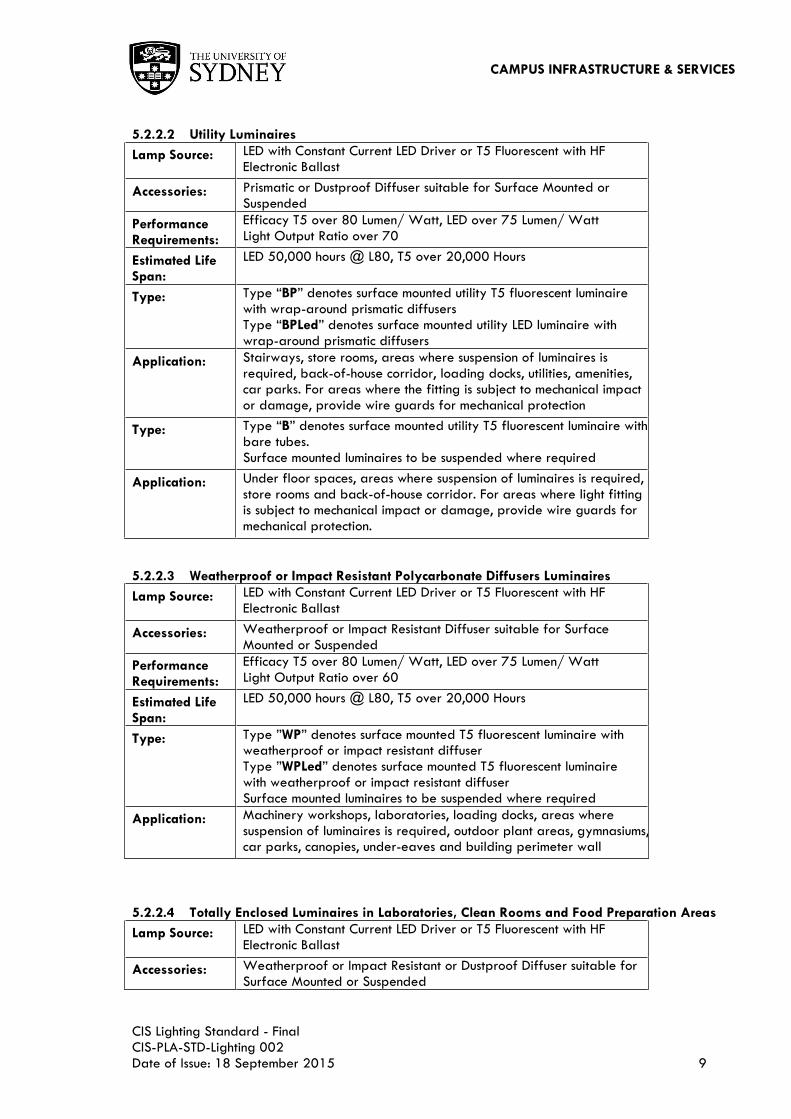
5.2.2.2 Utility Luminaires
Lamp Source: LED with Constant Current LED Driver or T5 Fluorescent with HF Electronic Ballast
Accessories: Prismatic or Dustproof Diffuser suitable for Surface Mounted or Suspended
Performance Requirements:
Efficacy T5 over 80 Lumen/ Watt, LED over 75 Lumen/ Watt Light Output Ratio over 70
Estimated Life Span:
LED 50,000 hours @ L80, T5 over 20,000 Hours
Type: Type ―BP‖ denotes surface mounted utility T5 fluorescent luminaire with wrap-around prismatic diffusers Type ―BPLed‖ denotes surface mounted utility LED luminaire with wrap-around prismatic diffusers
Application: Stairways, store rooms, areas where suspension of luminaires is required, back-of-house corridor, loading docks, utilities, amenities, car parks. For areas where the fitting is subject to mechanical impact or damage, provide wire guards for mechanical protection
Type: Type ―B‖ denotes surface mounted utility T5 fluorescent luminaire with bare tubes. Surface mounted luminaires to be suspended where required
Application: Under floor spaces, areas where suspension of luminaires is required, store rooms and back-of-house corridor. For areas where light fitting is subject to mechanical impact or damage, provide wire guards for mechanical protection.
5.2.2.3 Weatherproof or Impact Resistant Polycarbonate Diffusers Luminaires
Lamp Source: LED with Constant Current LED Driver or T5 Fluorescent with HF Electronic Ballast
Accessories: Weatherproof or Impact Resistant Diffuser suitable for Surface Mounted or Suspended
Performance Requirements:
Efficacy T5 over 80 Lumen/ Watt, LED over 75 Lumen/ Watt Light Output Ratio over 60
Estimated Life Span:
LED 50,000 hours @ L80, T5 over 20,000 Hours
Type: Type ‖WP‖ denotes surface mounted T5 fluorescent luminaire with weatherproof or impact resistant diffuser Type ‖WPLed‖ denotes surface mounted T5 fluorescent luminaire with weatherproof or impact resistant diffuser Surface mounted luminaires to be suspended where required
Application: Machinery workshops, laboratories, loading docks, areas where suspension of luminaires is required, outdoor plant areas, gymnasiums, car parks, canopies, under-eaves and building perimeter wall
5.2.2.4 Totally Enclosed Luminaires in Laboratories, Clean Rooms and Food Preparation Areas
Lamp Source: LED with Constant Current LED Driver or T5 Fluorescent with HF Electronic Ballast
Accessories: Weatherproof or Impact Resistant or Dustproof Diffuser suitable for Surface Mounted or Suspended

CAMPUS INFRASTRUCTURE & SERVICES
CIS Lighting Standard - Final CIS-PLA-STD-Lighting 002 Date of Issue: 18 September 2015 10
Performance Requirements:
Efficacy T5 over 80 Lumen/ Watt, LED over 75 Lumen/ Watt Light Output Ratio over 60
Estimated Life Span:
LED 50,000 hours @ L80, T5 over 20,000 Hours
Type: Type ―LAB‖ denotes recessed LED or T5 fluorescent luminaire with totally enclosed IP44 diffuser
Application: Chemical/ biological laboratories, research laboratories, clean rooms and commercial grade food preparation areas
5.2.2.5 Internal LED Downlights
Lamp Source: LED with Constant Current LED Driver
Accessories: High Output Low Glare Reflector, Round or Square Ceiling Trim or Wall Washer
Performance Requirements:
LED over 75 Lumen/ Watt Light Output Ratio over 70
Estimated Life Span:
LED 50,000 hours @ L80
Type: Type ―LAB‖ denotes recessed LED or T5 fluorescent luminaire with totally enclosed IP44 diffuser
Application: Chemical/ biological laboratories, research laboratories, clean rooms and commercial grade food preparation areas
Type: Type ―DLed‖ denotes recessed LED down lights Type ―SLed‖ denotes surface mounted LED down lights
Application: Foyers, circulation areas, lift lobbies, conference rooms, lecture theatres and library
5.2.2.6 Internal Rectangular Extruded Aluminium Suspended Luminaires
Lamp Source: LED with Constant Current LED Driver or T5 Fluorescent with HF Electronic Ballast.
Accessories: Prismatic Diffuser or Louvres, Rectangular or Round, Direct or Indirect and Suspending
Performance Requirements:
Efficacy T5 over 85 Lumen/Watt, LED over 75 Lumen/Watt Light Output Ratio over 60%.
Estimated Life Span:
LED 50,000 hours @ L80, T5 over 20,000 Hours.
Type: Type ―SELed‖ denotes slim rectangular aluminium extruded LED luminaires with louvres or prismatic diffusers.
Application: Library, lobbies, lecture theatres, conference rooms, teaching spaces or laboratories with high ceiling or no ceiling. For areas with VDU or projector screens - use only low brightness louvre type luminaire.
Criteria Relevant To Selecting Down Lights All new downlights to be selected and installed within The University of Sydney buildings must be energy efficient LED lamps. When specifying downlights, the project electrical engineer/ lighting consultant must pay particular attention to the following issues:
a. Glare caused by LED lamps must comply with the requirements set by AS1680.
b. Uniformity of light distribution must comply with the requirements of AS1680.

CAMPUS INFRASTRUCTURE & SERVICES
CIS Lighting Standard - Final CIS-PLA-STD-Lighting 002 Date of Issue: 18 September 2015 11
Incandescent, IRC, tungsten halogen and inefficiency HID lamps, e.g. mercury vapour lamps must not be specified for all University building projects. Refer to clause 5.8.8 for more details.
5.2.3 GENERAL LUMINAIRE CONSTRUCTION
Luminaires are to be well-constructed, good quality, durable and possess the following features:
a. RIGIDITY: The materials, body shape, and method of manufacture provide adequate rigidity
to prevent warping or sagging when installed;
b. RELAMPING: Lamps must be easily removable from the front of the luminaire when recess
mounted in a ceiling;
c. BODY SHAPE: Rectangular and square luminaires must have straight parallel edges and square
corners;
d. SURFACE MOUNTING: For fixing of surface-mounted luminaires to ceilings or walls provide
fixing holes as follows:
i. Square and Rectangular Luminaires: minimum four symmetrical holes; ii. Circular Luminaires: minimum three holes.
e. SUSPENSION MOUNTING: Provide suspensions and luminaire suspension connectors capable
of supporting, without damage, five times the mass of the luminaire, or 25kg, whichever is the
greater;
f. REFLECTOR & LENS RETENTION: Provide vibration resistance and retention of the reflector or
lens;
g. MANUFACTURER‘S MARKING: Provide a durable non-fading permanently affixed label on all
luminaires indicating the manufacturer‘s name, catalogue number and compliance with AS/NZS;
h. MATERIALS: Use zinc-coated steel, grade 304 stainless steel, extruded aluminium or other
equivalent performance materials unless otherwise approved by the issuer of this standard.
These material thicknesses apply:
i. Minimum zinc-coated steel thickness of 0.6mm provided adequate thickness is achieved by body shape and folding techniques, otherwise 1mm;
ii. Minimum grade 304 stainless steel thickness 1mm; iii. Minimum extruded aluminium thickness 1mm.
5.2.4 DOWNLIGHT CONSTRUCTION
Downlights are to be well-constructed, good quality, durable and have the following features:
a. FIXINGS: Provide a minimum of three clamping points from the rim to the ceiling fabric;
b. SUPPORT FLANGE: Provide a minimum of 5mm support flange around ceiling hole cut outs for
small downlights, and 10mm for larger downlights. Trim less downlights are unacceptable;
c. REMOVABILITY: The downlight must be removable from underneath the ceiling without
damaging the luminaire or the ceiling;
d. BALLAST HOUSING: Provide central or remote electronic ballast housings. Downlights with
offset ballasts and uneven balance may cause distortion of ceiling materials and are
unacceptable.
5.2.5 ADDITIONAL EQUIPMENT
Spotlights utilised in auditoriums and lecture theatres greater than 4m in height require lifters to enable the lights to be lowered. This allows for ease of adjustment of the spot lights. Lifters are to be provided from a reputable manufacturer – e.g. ReelTech – and be selected for the appropriate weights of the spot light luminaires and luminaire supports.

CAMPUS INFRASTRUCTURE & SERVICES
CIS Lighting Standard - Final CIS-PLA-STD-Lighting 002 Date of Issue: 18 September 2015 12
5.3 EXTERNAL
5.3.1 GENERAL REQUIREMENTS
Pole or building exterior wall mounted luminaires with a downwards / horizontal direction are to be used where feasible to minimise upward spill light and light pollution. Should upward facing luminaires be utilised to illuminate facades, landscape and exterior features, approval from the Sydney University CIS department is to be obtained. Where exterior lighting is utilised, and where relevant, compliance with AS 4282 – ‗Control of the obtrusive effects of exterior lighting‘ is to be adhered to. In-ground up lights be avoided due to higher risks of damage, moisture ingress and premature failure. Bollard lights must be avoided in the building entry, footpath and landscape areas due to the frequency of vandalism and accidental damage by vehicles. Approval of the CIS Electrical Services Engineer must be sought for use of exterior lighting which deviates from the Deemed to Comply Luminaire Schedule (CIS-ENG-F006).
Lamp Source: LED with Constant Current LED Driver.
Accessories: High Impact Polycarbonate Diffuser, Metal Housing and Optional Anti-Glare Frost Glass.
Performance Requirements:
LED over 70 Lumens/ Watt; Minimum IP56 Rating Light Output Ratio over 60%.
Estimated Life Span:
LED 50,000 hours @ L80.
Type: Type ―WPLed‖ denotes post top mounted external LED light fitting with polycarbonate diffusers.
Application: Pedestrian walkways, secondary roads, car parks and parks/ grass areas.
5.3.2 EXTERIOR LIGHT POLES, FIXINGS AND WIRING
Design and specification of exterior luminaires installations must fulfil the following requirements:
a. STRUCTURAL CALCULATIONS: Provide wind loading calculations for all pole Installations;
b. FIXING MATERIALS: Use stainless steel hardware and fixings with tamper-resistant heads;
c. RAG BOLT FIXINGS: Use hot-dip galvanised rag-bolt assemblies installed in a concrete plinth
finished at the finished surface level for hard surfaces, and not less than 50mm above finished
ground surface levels;
d. IN-GROUND WIRING: Install PVC-insulated wiring in underground conduits utilising the ―loop in
loop out‖ principle to each luminaire. Do not use intermediate junction boxes or T-off boxes;
e. WIRING SIZING: Underground circuits must be wired in minimum 4mm2 cables. Use oversize
conductors to the first luminaire to maintain voltage drop to less than 1% at the first luminaire;
f. LIGHT FITTINGS: Must be individually protected by HRC fuses, with adequate ventilation and
degree of protection (IP rating). Reflectors must be manufactured from high quality (purity)
aluminium;
g. POLES: Multi-functional galvanised poles must be used. They are to be painted with one coat
of metal primer, one undercoat, plus two top coats of enamel paint. Approved anti-corrosive
powder coating is acceptable. Colours are to be in accordance with the CIS Grounds and
Heritage Standards requirements. HRC fuses must be installed at the base of the pole and be
accessible from the pole inspection plate. Exit conduits must be installed at the last pole for

CAMPUS INFRASTRUCTURE & SERVICES
CIS Lighting Standard - Final CIS-PLA-STD-Lighting 002 Date of Issue: 18 September 2015 13
future installations. Poles must be provided with an engraved stainless steel label affixed to the
front of the inspection plate cover as a means of identification. The information must include the
University asset number and lamp type and must be transferred to the University record
exterior lighting 'as-built' drawings and registered according to the CIS Asset Management
Standard by the Contractor.
5.4 CUSTOMISED LUMINAIRES
Custom-designed, bespoke or modified special luminaries must not be specified or used without written formal approval from the CIS Electrical Services Engineer as they often incur additional cost and performance is difficult to ascertain and guarantee. Customised luminaires must only be considered for historic restoration projects where standard products may not be available. If approved, designers are to specify, and contractors must supply:
a. upfront purchase of 10% extra basic carcass / bodies for spares and alterations;
b. standard commercial paint and powder coat colours that are readily and inexpensively
available in the local market;
c. 12 month warranty for the installed luminaire, ballast and lamp;
d. Evidence of thermal and photometric performance testing by a NATA-accredited laboratory.
5.5 REDUNDANT EQUIPMENT
Remove redundant luminaires, equipment and wiring, including in accessible ceiling spaces, and make good any exposed surfaces before commencing the installation of new wiring.
6 LIGHTING SYSTEM DESIGN
6.1 STANDARDS AND CODES
Interior and exterior artificial lighting are to comply with, but not limited to the following: a. NCC;
b. AS/NZS 1680;
c. AS/NZS 1158;
d. AS/NZS 4282 (where required);
e. AS/NZS 2293;
f. AS/NZS 3000;
g. AS/NZS 1428.2;
h. Sydney University ICT Audio Visual Specification;
i. Sydney University CIS Security Specification;
j. Sydney University CIS Communications Specification.

CAMPUS INFRASTRUCTURE & SERVICES
CIS Lighting Standard - Final CIS-PLA-STD-Lighting 002 Date of Issue: 18 September 2015 14
6.2 DESIGN PARAMETERS
6.2.1 COMPUTERISED LIGHT MODELLING
The following computerised lighting calculation point densities must be used to ensure accurate and representative values are obtained and displayed:
a. Interior spaces 0.2m grid;
b. Exterior spaces 0.5m grid (horizontal and vertical).
Note: Use of excessive point spacing may lead to results with inaccuracies due to the low effective sampling rate against the luminaire spacing. Lighting design calculations must not include inter-reflection for calculations in spaces with high workstation partitions or shelving. They are to be based on minimum maintained average levels i.e. the average lighting level over the effective work area at the end of the cleaning / re-lamping cycle.
TABLE 1 LIGHTING SYSTEM CALCULATION PARAMETERS
Design parameter Calculation requirement Effective work area 0.5m from walls for enclosed spaces
Work plane height 0.75m for desk / 0.9m bench and 0m for travel
areas, or as otherwise clearly defined by the relevant Australian Standard and space use.
Storage or library shelving work plane Work plane is to be a vertical surface taken from
the middle of the lowest shelf to the middle of the highest shelf tiers.
Reflection factors Plaster, tile or white painted Ceilings 70%
Painted Walls 50% Carpeted Floors 15% Tiled floors 20% Off form concrete 20%
As part of the maintenance regime, a Light Loss Factor (LLF) is to be applied to all design calculations. For T5 fluorescent technology, this is to be based on the requirements as outlined in AS/NZS 1680. Australian standards do not yet address the maintenance of Solid State Lighting (LED Technology). However a LLF is still required to be utilised during the design process. Where LED luminaires are utilised, the fitting is to have a rated life of 50,000 at L80, allowing the designer to utilise a Maintenance Factor of 0.8. Cleaning of rooms / areas is to be undertaken on a regular basis throughout the university. A LLF of 0.8 has been determined based on the above to allow for a balance between energy use (the lower the LLF, the more fittings are required in order to achieve the required illuminance levels) and maintenance of luminaires. The above applies to Audio Visual requirements. AV contrast ratio refers to projected lux to ambient lux. AV lighting calculations must be approved by the ICT Audio Visual engineer prior to design sign-off. Refer to Table 1A for Audio Visual system calculations.

CAMPUS INFRASTRUCTURE & SERVICES
CIS Lighting Standard - Final CIS-PLA-STD-Lighting 002 Date of Issue: 18 September 2015 15
TABLE 1A AUDIO VISUAL SYSTEM CALCULATION PARAMETERS
Design parameter Calculation requirement Projection Calculation Vertically, indicating the screens, under all three
pre-sets (pre-set ‗all off’ not required) Pre-set / Contrast Ratios Pre-set 2 - 7:1
Pre-set 3 - 15:1 Pre-set 4 - 50:1 Blind control must be considered where daylight impacts AV projection.
6.2.2 WHOLE OF LIFE COST AND PERFORMANCE CONSIDERATIONS
Whole-of-life performance of proposed luminaires must be submitted for review and approval by the issuer of this standard. Designers must submit the whole-of-life cost performance evaluation using the spreadsheet form (CIS-ENG-F005). An example of this form is provided in Attachment 1 but must be downloaded from the Form section on the web site.
6.3 DESIGN SOFTWARE
Lighting designers and contractors must carry out lighting calculations for typical and unique spaces using University approved computer models. Current compliant software‘s are provided in Attachment 2. Equivalent models can be accepted after review and approval by the issuer of this standard. Designers must provide native calculation files and PDF printouts of illuminance grids which will be used to verify the installed lighting performance.
6.4 LUMINAIRES AND ILLUMINANCE LEVEL REQUIREMENTS
Table 2 provides luminaires to be used for typical interior spaces as well as the illuminance level requirements to be met.
TABLE 2 INTERIOR LIGHTING DESIGN LEVELS
Areas Luminaire types
*
Minimum Maintained
Horizontal Average Light
Levels
General spaces
Amenities DLed 80 lux
Amenities for persons
with disability
DLed or TP 200 lux
Lecture and Seminar
rooms
**
TL or SL Dimmable 10 - 240 lux
200 lux vertical at 1.6m
AFFL – achieved by (2)
dimmable LED spotlights
with barn doors
Corridors DLed 150 lux

CAMPUS INFRASTRUCTURE & SERVICES
CIS Lighting Standard - Final CIS-PLA-STD-Lighting 002 Date of Issue: 18 September 2015 16
Areas Luminaire types
*
Minimum Maintained
Horizontal Average Light
Levels
General Computer
Classrooms
**
TL or TI Dimmable 10 - 240 lux
200 lux vertical at 1.6m
AFFL – achieved by (2)
dimmable LED spotlights
with barn doors
General Office areas TP or TL 320 lux
Meeting or Multipurpose
Room
TP or TLor DLed Switchable level 240/450 lux
Meeting room general TP or TL 320 lux
Meeting room with AV
facility
TP or TL or DLed Dimmable 10 - 320 lux
Reception / Lobby TP or TL or DLed As per AS1680
Stairways Hi-specification LED bi-level
lights with occupancy sensors
As per AS1680
Store Rooms – depends
on task
TP or BP As per AS1680
Video Conference
This is a requirement
wherever VC is utilised
**
TP or TL or DLed
Direct / indirect main source,
plus dimmable LED downlights
Horizontal illuminance - 400
lux at 0.75 m
Vertical illuminance – 400
lux at 1.6 m (standing height
for presenter)
Specialized dimmable LED
spotlights are required for
Video Conferencing
equipment to match the
lighting quality for the
recipient.
Laboratories
Biological Hazard Area
(PC1-3)
LABLed or LAB To respective code
Chemical/Process/Research
Biological/ Laboratory
LABLed or LAB 600 lux
Computer/ Internet/ Signals
Instrument / Laboratory
TP or TL 320 lux
General Laboratory LABLed –or LAB 450 lux
Workshop TP or SELed 600 lux
Theatre

CAMPUS INFRASTRUCTURE & SERVICES
CIS Lighting Standard - Final CIS-PLA-STD-Lighting 002 Date of Issue: 18 September 2015 17
Areas Luminaire types
*
Minimum Maintained
Horizontal Average Light
Levels
General Lecture (with
lectern / desk task light)
**
TP or TL or DLed Dimmable 10 - 240 lux (must
not impact on contrast ratios)
200 lux vertical at 1.5m
AFFL – achieved by (2)
dimmable LED spotlights.
*Refer to section 5 for details of luminaire types. ** Refer to AETM guidelines. AV lighting calculations must be approved by the ICT Audio Visual engineer prior to design sign-off.
Areas Luminaire types
*
Minimum Maintained
Horizontal Average Light
Levels
Sports Facilities
Gymnasiums TP 300 lux horizontal at 1m
AFFL
Uniformity 0.5
Sports Halls TP 300 lux horizontal at 1m
AFFL
Uniformity 0.5
Internal Building Car parking
Parking bays and access
bays (low risk)
WPLed or BPLed 75 Lux
Pedestrian areas, lifts &
stairs
WPLed or BPLed 100 lux
Ramps, corners and
intersections (high risk)
WPLed or BPLed 150 Lux
Vehicle entrance/exit
zones
WPLed or BPLed 75 lux (night)
800 lux (day)
Residential Buildings
Bedrooms LED surface oyster lights, or
Compact fluorescent oyster
lights
To NCC section J & AS1680
Common Rooms BPLed - LED surface 100 lux
*Refer to section 5.2.2 for details of luminaire types. Table 3 outlines the external illuminance level requirements.

CAMPUS INFRASTRUCTURE & SERVICES
CIS Lighting Standard - Final CIS-PLA-STD-Lighting 002 Date of Issue: 18 September 2015 18
TABLE 3 EXTERIOR DESIGN LIGHTING LEVELS
Areas Maintained
Average Light
Levels
Minimum Light at
any point
Uniformity
Main pedestrian walkways AS/NZS 1158 AS/NZS 1158 AS/NZS 1158
Secondary pedestrian
walkways
AS/NZS 1158 AS/NZS 1158 AS/NZS 1158
Main Roads AS/NZS 1158 AS/NZS 1158 AS/NZS 1158
Secondary Roads AS/NZS 1158 AS/NZS 1158 AS/NZS 1158
Park / grass areas AS/NZS 1158 AS/NZS 1158 AS/NZS 1158
General Sport Ovals 50 N/A 0.3
Event Sports Oval
AS 2560.2.3
AS 2560.2.3
AS 2560.2.3
Tennis Courts AS 2560.2.1 AS 2560.2.1 AS 2560.2.1
External Carpark Areas AS/NZS 1158 AS/NZS 1158 AS/NZS 1158
DDA Areas AS/NZS 1428.2 AS/NZS 1428.2 AS/NZS 1428.2
7 LIGHTING CONTROL SYSTEMS
7.1 GENERAL REQUIREMENTS
The University of Sydney has adopted a Sustainability Framework to reduce energy consumption by installing energy efficient lighting and Intelligent Lighting Control Systems (LCS). Across the University of Sydney buildings, lighting represents approximately 30% of the total building electrical consumption. Therefore, energy efficient lighting and intelligent lighting control systems play an important role in assisting with the reduction of energy consumption in the University. The University of Sydney CIS Lighting standard has established minimum performance requirements for the energy efficient lighting systems. A list of Deemed-to-Comply Lighting Suppliers and their Deemed-to-Comply energy efficient luminaires (various LED and T5 fluorescent lighting) have been chosen to be used for the University CIS Capital Works program. All lighting control systems must comply with the NCC Section J as a minimum and minimise energy consumption and maximise lamp life. An important requirement of the lighting control system is to facilitate turning the lights ‗OFF‘ when not in use. Light output and power consumption must be able to be reduced when full light output is not needed. Mandatory requirements include:
a. Lights ON each floor of a building must be controlled by a separate automatic control device;
b. Light switches and controls must be provided in each room / area;
c. Daylighting controls must be provided where sufficient daylight illumination can be provided to
a space;

CAMPUS INFRASTRUCTURE & SERVICES
CIS Lighting Standard - Final CIS-PLA-STD-Lighting 002 Date of Issue: 18 September 2015 19
d. Automatic timer switch and occupancy sensor must be provided to ensure lights are OFF after
occupants leave the room and outside of business hours;
e. Separate switching of any display lighting and general lighting must be provided;
f. Automatic 365-days programmable timer switch and photo-electric sensors must be provided
for controlling exterior lighting ON and OFF operation.
7.2 LIGHTING CONTROLS IN UNIVERSITY TEACHING AREAS AND OFFICES
In order for the lighting control system to be operated in a satisfactory manner and achieve the desired energy savings, a comprehensive Lighting Control Strategy is required. The University has established the following Lighting Control Strategy in all the teaching areas and offices. There are basic four (4) controls strategies: Occupancy Controls, Daylight Harvesting, Institutional Controls and Local Tuning:
a. Occupancy Controls (OC) are defined as automatic adjustment of light levels in response to
the presence of occupants. It includes constant occupancy monitoring and illumination controls.
b. Daylight Harvesting (DH) is defined as the automatic adjustment of light levels in response to daylight. It includes constant daylight sensor monitoring and illumination controls or time based controls.
c. Interface Controls (IC) is defined as adjusting light levels to task-specific requirements by pre-
set scene control, dimming and switching. It includes integration with Zone based Lighting
Control and/ or Building Management and Control systems.
d. Local Tuning (LT) is defined as an individual adjustment of their own light levels to their
personal preference. It includes manual user local ON/OFF and dimmer controls.
7.3 LIGHTING CONTROL STRATEGIES
TABLE 4 OUTLINES THE LIGHTING CONTROL STRATEGIES
Room Function *Lighting
Control
Controls
Methodology
Circuit
Dimmable
Control
System
Approved Luminaire
Type
Auditoriums, Lecture
Theatres with Video
Projectors
IC, OC K Yes DALI TL, TLLed, SL, SLLed,
DLed.
Computer Rooms with
Video Projectors
IC, OC, DH J Yes DALI TL, TLLed, TI, SL,
SLLed, DLed
Conference Rooms
with Video
Projectors
IC, OC, DH J Yes DALI TL, TP, TI, TLLed, SP,
SL, SLLed, DLed
Seminar, Lecture,
Computer Rooms
IC, OC, DH F Yes DALI TL, TP, TLLed, SP, SL,
SLLed, DLed.
Meeting Rooms IC, OC, DH F Yes DALI TL, TP, TLLed, SP, SL,
SLLed, DLed

CAMPUS INFRASTRUCTURE & SERVICES
CIS Lighting Standard - Final CIS-PLA-STD-Lighting 002 Date of Issue: 18 September 2015 20
Room Function *Lighting
Control
Controls
Methodology
Circuit
Dimmable
Control
System
Approved Luminaire
Type
Group Study
Rooms
LT, OC B No DALI TL, TP, TLLed,
TPLed,SP, SPLed, SL,
DLed
Individual Offices LT, OC B No DALI TL, TP, TLLed, SP, SL,
SLLed, DLed
Open Plan Offices LT, OC, DH D No DALI TL, TP, TLLed, SP, SL,
SLLed, DLed
General, Dry
Laboratories
LT P No DALI TP, TPLed, ,SELed
(recess)
Wet, Research
Laboratories
LT A No DALI LAB
Library General
Areas
OC, DH M No DALI TL, TP, TLLed,
SP,SL,SELed,DLed
Library 24 Hours
Areas, Aisle Areas
OC, DH N No DALI TL, TP, TLLed, SP,
SPLed, SL,SLLed,
SELed,DLed
Lift Lobbies OC, DH M No DALI TP,TPLed, TL, TLLed,
SP, SPLed, DLed,
SELed
Workshops with
Rotating Machines
LT A No 240V
Switch
TP, SP, SLLed, TLLed,
WP
Communications,
Plant Rooms
LT A
No 240V
Switch
BP, BPLed WP,
WPLed
Electrical Switch
Rooms, Electrical
Cupboard
LT A
No 240V
Switch
BP, BPLed
Receptions LT, DH E No DALI TP, TPLed, TL, TLLed,
TI, TILed, SP, SPLed,
DLed, SELed
Circulation or Foyers
with daylight
contribution
OC, DH Q No DALI TP, TPLed, SP,SPLed,
TL, TLLed, DLed,
SELed

CAMPUS INFRASTRUCTURE & SERVICES
CIS Lighting Standard - Final CIS-PLA-STD-Lighting 002 Date of Issue: 18 September 2015 21
Room Function *Lighting
Control
Controls
Methodology
Circuit
Dimmable
Control
System
Approved Luminaire
Type
Circulation or Foyers
without daylight
contribution
OC M No DALI TP, TPLed, TL, TLLed,
SP, SPLed, DLed,
SELed
Break-out Rooms LT, OC, DH D No DALI TP, TPLed, TL, TLLed,
SP, SPLed, DLed,
SELed
High Ceiling Large
Rooms
LT, OC, DH D No DALI SELed, DLed
Sensitive areas LT A Yes DALI TP, TI, TILed, TL,
TLLed, DLed
Interview / First
Aid Rooms
LT, OC C No DALI TP, TPLed, SP, SPLed,
TI, TLLed
Gymnasiums LT, OC P No DALI TP, TPLed, SELed,
DLed,
Cleaners and Store
Rooms
LT H
(1 hour)
No 240V
Switch
BP, B
Loading Docks LT A No 240V
Switch
WPLed
External Circulation DH L No DALI WP, PLed
Stairwell without
Daylight Contribution
OC R No DALI TP, SP, TLed, SBP
Stairwell with
Daylight
Contribution
OC, DH Q No DALI TP, SP, TLed, SBP,
WP
Toilets and
Bathrooms, Showers
OC O No DALI TP, TLed, DLed
Student
Accommodation
Bedrooms
OC G No DALI Surface Oyster LED
Kitchens OC O or N No DALI SP, BP
*Refer to section 7.2 for control system requirements

CAMPUS INFRASTRUCTURE & SERVICES
CIS Lighting Standard - Final CIS-PLA-STD-Lighting 002 Date of Issue: 18 September 2015 22
7.4 LIGHTING CONTROL METHODOLOGY
The following tables describe the lighting controls methodology for energy saving and are applicable to standard room types as outlined in section 7.2. Lighting controls methodology for the rooms not shown below must be developed based on the Project Brief and in discussions with and approved by the CIS Electrical Engineer and Project Manager. Sensor detection time limits have been nominated in the table below. These shall be re-programmable at time of commissioning at the clients request.
TABLE 5 OUTLINES THE LIGHTING CONTROL METHODOLOGY
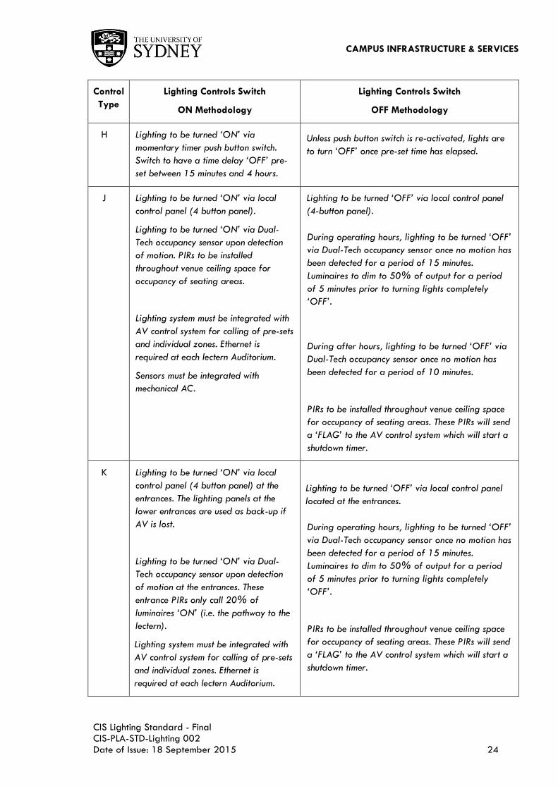
Control
Type
Lighting Controls Switch
ON Methodology
Lighting Controls Switch
OFF Methodology
A Lighting to be turned ‘ON’ via local
switch.
Default mode of luminaires is OFF.
Lighting to be turned ‘OFF’ via local switch.
B Lighting to be turned ‘ON’ via local
switch.
Lighting to be turned ‘OFF’ via local switch.
PIR occupancy sensor to be activated once lighting is
switched on. Should no motion be detected for a
period of 15 minutes, the sensor will switch lights
‘OFF’.
C
PIR to switch lights ‘ON’ upon detection
of motion. PIR to turn lights ‘OFF’ once no motion has been
detected for a period of 15 minutes.
D Lighting to be turned ‘ON’ via local
switch.
Lighting to be turned ‘ON’ via Dual-
Tech occupancy sensor upon detection
of motion. Lighting to the perimeter
zones of the room will only turn on
should the sensor detect illuminance
levels lower than the set minimum.
Lighting to be turned ‘OFF’ via local switch.
Lighting to be turned ‘OFF’ via Dual-Tech
occupancy sensor once no motion has been detected
for a period of 15 minutes.
Perimeter Lighting to be turned ‘OFF’ via Dual-Tech
occupancy sensor should the sensor detect
illuminance levels greater than the set maximum.

CAMPUS INFRASTRUCTURE & SERVICES
CIS Lighting Standard - Final CIS-PLA-STD-Lighting 002 Date of Issue: 18 September 2015 23
Control
Type
Lighting Controls Switch
ON Methodology
Lighting Controls Switch
OFF Methodology
E Lighting to be turned ‘ON’ via local
switch.
Lighting to be turned ‘ON’ via Dual-
Tech occupancy sensor upon detection
of motion.
Lighting to be turned ‘OFF’ via local switch.
During operating hours, lighting to be turned ‘OFF’
via Dual-Tech occupancy sensor once no motion has
been detected for a period of 30 minutes.
During after hours, lighting to be turned ‘OFF’ via
Dual-Tech occupancy sensor once no motion has
been detected for a period of 10 minutes.
Perimeter Lighting to be turned ‘OFF’ via Dual-Tech
occupancy sensor should the sensor detect
illuminance levels greater than the set maximum.
F Lighting to be turned ‘ON’ via local
control panel (4 button panel).
Lighting to be turned ‘ON’ via Dual-
Tech occupancy sensor upon detection
of motion at the entrances. These
entrance PIRs only call 20% of
luminaires ‘ON’ (i.e. the pathway to the
lectern).
Lighting system must be integrated with
AV control system for calling of pre-sets
and individual zones. Ethernet is
required at each lectern Auditorium.
Sensors must be integrated with
mechanical AC.
Lighting to be turned ‘OFF’ via local control panel
(4-button panel).
During operating hours, lighting to be turned ‘OFF’
via Dual-Tech occupancy sensor once no motion has
been detected for a period of 15 minutes.
During after hours, lighting to be turned ‘OFF’ via
Dual-Tech occupancy sensor once no motion has
been detected for a period of 10 minutes.
Perimeter Lighting to be turned ‘OFF’ via Dual-Tech
occupancy sensor should the sensor detect
illuminance levels greater than the set maximum.
Lighting to be turned ‘OFF’ via AV control system.
PIRs to be installed throughout venue ceiling space
for occupancy of seating areas. These PIRs will send
a ‘FLAG’ to the AV control system which will start a
shutdown timer.
G Lighting to be turned ‘ON’ via local
switch and key card system.
Lighting to be turned ‘OFF’ via local switch.
Automatic 3 minutes after remove key card.
Lighting to be turned ‘OFF’ 3 minutes once key card
is removed.
CAMPUS INFRASTRUCTURE & SERVICES
CIS Lighting Standard - Final CIS-PLA-STD-Lighting 002 Date of Issue: 18 September 2015 24
Control
Type
Lighting Controls Switch
ON Methodology
Lighting Controls Switch
OFF Methodology
H Lighting to be turned ‘ON’ via
momentary timer push button switch.
Switch to have a time delay ‘OFF’ pre-
set between 15 minutes and 4 hours.
Unless push button switch is re-activated, lights are
to turn ‘OFF’ once pre-set time has elapsed.
J Lighting to be turned ‘ON’ via local
control panel (4 button panel).
Lighting to be turned ‘ON’ via Dual-
Tech occupancy sensor upon detection
of motion. PIRs to be installed
throughout venue ceiling space for
occupancy of seating areas.
Lighting system must be integrated with
AV control system for calling of pre-sets
and individual zones. Ethernet is
required at each lectern Auditorium.
Sensors must be integrated with
mechanical AC.
Lighting to be turned ‘OFF’ via local control panel
(4-button panel).
During operating hours, lighting to be turned ‘OFF’
via Dual-Tech occupancy sensor once no motion has
been detected for a period of 15 minutes.
Luminaires to dim to 50% of output for a period
of 5 minutes prior to turning lights completely
‘OFF’.
During after hours, lighting to be turned ‘OFF’ via
Dual-Tech occupancy sensor once no motion has
been detected for a period of 10 minutes.
PIRs to be installed throughout venue ceiling space
for occupancy of seating areas. These PIRs will send
a ‘FLAG’ to the AV control system which will start a
shutdown timer.
K Lighting to be turned ‘ON’ via local
control panel (4 button panel) at the
entrances. The lighting panels at the
lower entrances are used as back-up if
AV is lost.
Lighting to be turned ‘ON’ via Dual-
Tech occupancy sensor upon detection
of motion at the entrances. These
entrance PIRs only call 20% of
luminaires ‘ON’ (i.e. the pathway to the
lectern).
Lighting system must be integrated with
AV control system for calling of pre-sets
and individual zones. Ethernet is
required at each lectern Auditorium.
Lighting to be turned ‘OFF’ via local control panel
located at the entrances.
During operating hours, lighting to be turned ‘OFF’
via Dual-Tech occupancy sensor once no motion has
been detected for a period of 15 minutes.
Luminaires to dim to 50% of output for a period
of 5 minutes prior to turning lights completely
‘OFF’.
PIRs to be installed throughout venue ceiling space
for occupancy of seating areas. These PIRs will send
a ‘FLAG’ to the AV control system which will start a
shutdown timer.

CAMPUS INFRASTRUCTURE & SERVICES
CIS Lighting Standard - Final CIS-PLA-STD-Lighting 002 Date of Issue: 18 September 2015 25
Control
Type
Lighting Controls Switch
ON Methodology
Lighting Controls Switch
OFF Methodology
Sensors must be integrated with
mechanical AC.
L Photo-electric cells switch lights ‗ON‘
when external illuminance levels are
below the ‗sunset setting‘ on the PE
cell.
Photo-electric cells switch lights ‗OFF‘ when
external illuminance levels are greater than the
‗sunrise setting‘ on the PE cell.
M Lighting to be turned ‘ON’ via
occupancy sensor upon detection of
motion.
During operating hours, lighting to be turned ‘OFF’
via Dual-Tech occupancy sensor once no motion has
been detected for a period of 15 minutes.
During after hours, lighting to be turned ‘OFF’ via
Dual-Tech occupancy sensor once no motion has
been detected for a period of 10 minutes.
Perimeter Lighting to be turned ‘OFF’ via Dual-Tech
occupancy sensor should the sensor detect
illuminance levels greater than the set maximum.
N Lighting to be turned ‘ON’ via Dual-
Tech occupancy sensor upon detection
of motion.
Lighting to be turned ‘OFF’ via Dual-Tech
occupancy sensor once no motion has been
detected for a period of 15 minutes.
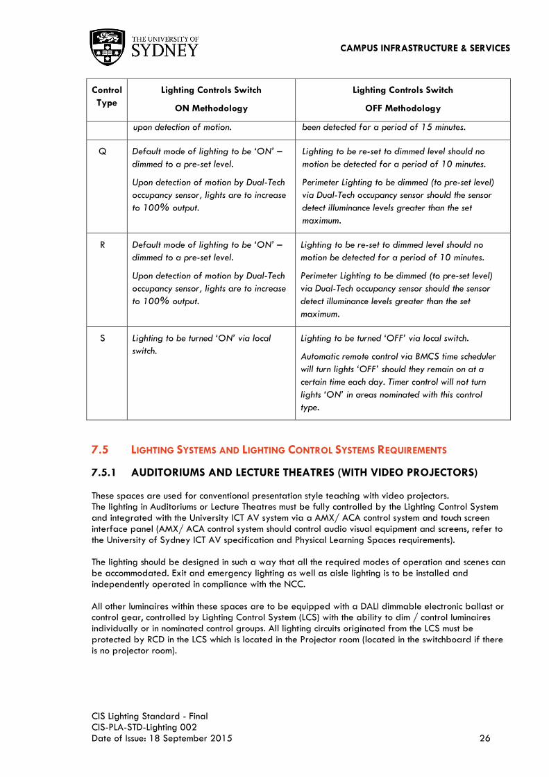
O Lighting to be turned ‘ON’ via Dual-
Tech occupancy sensor upon detection of
motion
Lighting to be turned ‘OFF’ via Dual-Tech
occupancy sensor once no motion has been detected
for a period of 15 minutes.
All cupboard and shower doors must have self-
closing doors.
P During operating hours, Lighting to be
turned ‘ON’ via local control panel.
During after hours, lighting to be turned
‘ON’ via Dual-Tech occupancy sensor
During operating hours, lighting to be turned ‘OFF’
via local control panel.
During after hours, lighting to be controlled via
Automatic time clock. Lighting to turn ‘OFF’ via
Dual-Tech occupancy sensor once no motion has
CAMPUS INFRASTRUCTURE & SERVICES
CIS Lighting Standard - Final CIS-PLA-STD-Lighting 002 Date of Issue: 18 September 2015 26
Control
Type
Lighting Controls Switch
ON Methodology
Lighting Controls Switch
OFF Methodology
upon detection of motion. been detected for a period of 15 minutes.
Q Default mode of lighting to be ‘ON’ –
dimmed to a pre-set level.
Upon detection of motion by Dual-Tech
occupancy sensor, lights are to increase
to 100% output.
Lighting to be re-set to dimmed level should no
motion be detected for a period of 10 minutes.
Perimeter Lighting to be dimmed (to pre-set level)
via Dual-Tech occupancy sensor should the sensor
detect illuminance levels greater than the set
maximum.
R Default mode of lighting to be ‘ON’ –
dimmed to a pre-set level.
Upon detection of motion by Dual-Tech
occupancy sensor, lights are to increase
to 100% output.
Lighting to be re-set to dimmed level should no
motion be detected for a period of 10 minutes.
Perimeter Lighting to be dimmed (to pre-set level)
via Dual-Tech occupancy sensor should the sensor
detect illuminance levels greater than the set
maximum.
S Lighting to be turned ‘ON’ via local
switch.
Lighting to be turned ‘OFF’ via local switch.
Automatic remote control via BMCS time scheduler
will turn lights ‘OFF’ should they remain on at a
certain time each day. Timer control will not turn
lights ‘ON’ in areas nominated with this control
type.
7.5 LIGHTING SYSTEMS AND LIGHTING CONTROL SYSTEMS REQUIREMENTS
7.5.1 AUDITORIUMS AND LECTURE THEATRES (WITH VIDEO PROJECTORS)
These spaces are used for conventional presentation style teaching with video projectors. The lighting in Auditoriums or Lecture Theatres must be fully controlled by the Lighting Control System and integrated with the University ICT AV system via a AMX/ ACA control system and touch screen interface panel (AMX/ ACA control system should control audio visual equipment and screens, refer to the University of Sydney ICT AV specification and Physical Learning Spaces requirements). The lighting should be designed in such a way that all the required modes of operation and scenes can be accommodated. Exit and emergency lighting as well as aisle lighting is to be installed and independently operated in compliance with the NCC. All other luminaires within these spaces are to be equipped with a DALI dimmable electronic ballast or control gear, controlled by Lighting Control System (LCS) with the ability to dim / control luminaires individually or in nominated control groups. All lighting circuits originated from the LCS must be protected by RCD in the LCS which is located in the Projector room (located in the switchboard if there is no projector room).

CAMPUS INFRASTRUCTURE & SERVICES
CIS Lighting Standard - Final CIS-PLA-STD-Lighting 002 Date of Issue: 18 September 2015 27
The general lighting must be controlled by the Lighting Control Systems at the LCD touch panel, four
buttons switch panel or AMX/ ACA touch screen at the lectern or automatically by occupancy sensors
with the following features:
a. Lighting should be enabled for normal use by the LCS based on the following five (5) minimum
pre-set scenes:
Pre-set 1 – General teaching without the use of video projectors.
All ceiling lighting and whiteboard lighting are ON with dimmable functionality. For
room ceiling higher than 3m, directional LED spot lights for lectern and stage
lighting are ON with dimmable functionality.
Minimum ambient illuminance levels of 240 lux at 0.7m AFFL and front of stage
vertical illuminance levels of 400 lux.
Pre-set 2 – Teaching with the aid of video projectors on and note taking.
All ceiling lighting and directional spot lights are ON with dimmable functionality.
Whiteboard lighting is OFF.
Minimum illuminance levels 240 lux at 0.7m AFFL, presenter and front of stage
illuminance levels of 400 lux vertical at 1.6 m AFFL. ANSI contrast ratio for
projected images versus ambient light on screen is 7:1. Colour temperature is to be
maintained whilst luminaires are dimmed.
Pre-set 3 – Teaching with the aid of video projectors, higher quality images and note taking.
All ceiling lighting and directional spot lights are ON with dimmable functionality.
Whiteboard lighting is OFF.
Minimum note taking illuminance levels 100 lux at 0.7m AFFL in audience areas,
presenter and front of stage illuminance levels of 400 lux vertical at 1.6 m AFFL.
ANSI contrast ratio for projected images versus ambient light on screen is 15:1.
Colour temperature is to be maintained whilst luminaires are dimmed.
Pre-set 4 – Teaching with the aid of video projectors, ―Cinematic‖ quality images, dark
ambient and no note taking.
The room ceiling lighting is user adjustable. Directional spot lights for lectern and
whiteboard lighting are OFF.
ANSI contrast ratio for projected images versus ambient light on screen is 50:1.
Lighting colour temperature must be maintained during dimming.
Pre-set 5 – Room not occupied.
All ceiling lighting and projector lighting must be OFF. The occupancy sensors will be
enabled.
b. An occupancy sensor in the spaces should ensure that the lighting is operational while the space
is in use. After the occupant leaves the room for 15 minutes (5 minutes during after-hours)
triggered by an occupancy sensor, the lighting should dim to 50% for 2 minutes and then switch

CAMPUS INFRASTRUCTURE & SERVICES
CIS Lighting Standard - Final CIS-PLA-STD-Lighting 002 Date of Issue: 18 September 2015 28
OFF. During presentation modes 1-4 as outlined above, the sensors are to be de-activated so
that the pre-set levels are maintained;
c. At the completion of each teaching lesson the lighting scene is to be set to pre-set 5, whereby
occupancy sensors will turn lights ‗OFF‘ once no motion has been detected for the selected
period of time;
d. Once the lights have turned OFF, the default scene upon detection of motion and re-activation
of the lights is pre-set 1;
e. There should be minimum of five (5) lighting control groups:
f. Front of room lights (minimum 2 groups for over 200 seats Auditoriums);
g. Rear of room lights (minimum 2 groups for over 200 seats Auditoriums);
h. Lighting near window (operated by daylight sensor under scenes 1 and 2);
i. White board lighting;
j. Lectern and stage lights;
k. Each lighting group (and individual luminaires where required) must be dimmable under the
control of the Lighting Control System;
l. The lights need to be physically zoned at the board to allow an L and R or L, C, R configuration
when dual projection is used. This will allow the dual use of projectors and whiteboards;
m. A separate zone based DALI lighting control system with dimmer and AMX/ ACA interface unit
must be provided in the projector room. The LCS shall operate independent of the AMX/ ACA
control system if the AMX/ ACA controller or AV system fail to operate;
n. Lighting near windows should be automatically switched OFF when room lighting level is above
the daylight sensor ‗high‘ setting and switch lights ON at ‗low‘ setting. The daylight sensors
should have delay in change of output of 5 seconds to accommodate for dramatic change in
outside weather conditions;
o. The LCS system should allow ad-hoc dimming control of each group by the AMX/ ACA touch
screen at the lectern, LCD touch panel in Projector room or other nominated location.
7.5.2 SEMINAR ROOMS AND LEARNING STUDIOS (FLAT FLOOR WITH VIDEO PROJECTORS)
These spaces are used for interactive presentation style teaching where the audience engages in participation with the presenter and each other. The rooms offer configurations of groups and pairs to promote collaboration, and problem solving. The lighting in Seminar Rooms and Learning Studios must be fully controlled by Lighting Control System and integrated with the University ICT AV system via a AMX/ ACA control system and touch screen interface panel (AMX/ ACA control system should control audio visual equipment and screens, refer to the University of Sydney ICT AV specification and Physical Learning Spaces requirements). The lighting should be designed in such a way that all the required modes of operation and scenes can be accommodated. Exit and emergency lighting is to be installed and independently operated in compliance with the NCC. All other luminaires within these spaces are to be equipped with a DALI dimmable electronic ballast or control gear, controlled by Lighting Control System (LCS) with the ability to dim / control luminaires individually or in nominated control groups. All lighting circuits must be protected by RCD in the switchboard.
The general lighting is to be controlled by the Lighting Control Systems at the room entry four buttons
switch panel or AMX/ ACA touch screen at the lectern or automatically by occupancy sensors with the
following features:
a. Lighting should be enabled for normal use by the LCS based on the following four (4) pre-set
scenes:
Pre-set 1 - General teaching and group leaning activities without the use of video projectors.

CAMPUS INFRASTRUCTURE & SERVICES
CIS Lighting Standard - Final CIS-PLA-STD-Lighting 002 Date of Issue: 18 September 2015 29
All ceiling lighting and whiteboard lighting are ON with dimmable functionality.
Minimum ambient illuminance levels of 240 lux at 0.7m AFFL and front of stage
vertical illuminance levels of 400 lux.
Pre-set 2 - Teaching with the aid of video projectors on and note taking.
All ceiling lighting and directional spot lights are ON with dimmable functionality.
Whiteboard lighting is OFF.
Minimum illuminance levels 240 lux at 0.7m AFFL, presenter and front of stage
illuminance levels of 400 lux vertical at 1.6 m AFFL. ANSI contrast ratio for
projected images versus ambient light on screen is 7:1. Colour temperature is to be
maintained whilst luminaires are dimmed.
Pre-set 3 - Teaching with the aid of video projectors, higher quality images and note taking.
All ceiling lighting and directional spot lights are ON with dimmable functionality.
Whiteboard lighting is OFF.
Minimum note taking illuminance levels 100 lux at 0.7m AFFL in audience areas;
presenter and front of stage illuminance levels of 400 lux vertical at 1.6 m AFFL.
ANSI contrast ratio for projected images versus ambient light on screen is 15:1.
Colour temperature is to be maintained whilst luminaires are dimmed.
Pre-set 4 - Room not occupied.
All ceiling lighting and projector lighting must be OFF. The occupancy sensors will be
enabled.
An occupancy sensor in the spaces should ensure that the lighting is operational while the space is in use. After the occupant leaves the room for 15 minutes (5 minutes during after-hours) triggered by an occupancy sensor, the lighting should dim to 50% for 2 minutes and then switch OFF. During presentation modes 1-3 as outlined above, the sensors are to be deactivated so that pre-set levels are maintained. At the completion of each teaching lesson, the lighting scene is to be set to pre-set 4, whereby occupancy sensors will turn lights ‗OFF‘ once no motion has been detected for the selected period of time.
b. Once the lights have turned OFF, the default scene upon detection of motion and re-activation
of the lights is pre-set 1.
c. There should be minimum of four (4) lighting control groups:
i. Front of room lights; ii. Rear of room lights; iii. Lighting near window (operated by daylight sensor under scenes 1 and 2); iv. White board lighting.
Each lighting group (and individual luminaires where required) must be dimmable under the control of
the Lighting Control System:
d. A separate zone based DALI lighting control system with dimmer and dimmable electronic
ballasts shall be provided in the electrical switchboard. The LCS shall operate independent of
the AMX/ ACA control system if the AMX/ ACA controller or AV system fail to operate. The
LCS shall not control the exit sign, emergency lighting and aisle lighting for occupant safety
egress.
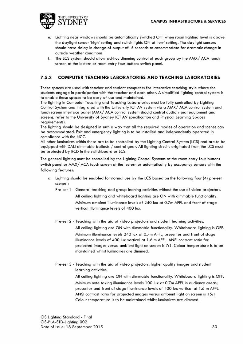
CAMPUS INFRASTRUCTURE & SERVICES
CIS Lighting Standard - Final CIS-PLA-STD-Lighting 002 Date of Issue: 18 September 2015 30
e. Lighting near windows should be automatically switched OFF when room lighting level is above
the daylight sensor ‗high‘ setting and switch lights ON at ‗low‘ setting. The daylight sensors
should have delay in change of output of 5 seconds to accommodate for dramatic change in
outside weather conditions.
f. The LCS system should allow ad-hoc dimming control of each group by the AMX/ ACA touch
screen at the lectern or room entry four buttons switch panel.
7.5.3 COMPUTER TEACHING LABORATORIES AND TEACHING LABORATORIES
These spaces are used with teacher and student computers for interactive teaching style where the students engage in participation with the teacher and each other. A simplified lighting control system is to enable these spaces to be easy-of-use and maintained. The lighting in Computer Teaching and Teaching Laboratories must be fully controlled by Lighting Control System and integrated with the University ICT AV system via a AMX/ ACA control system and touch screen interface panel (AMX/ ACA control system should control audio visual equipment and screens, refer to the University of Sydney ICT AV specification and Physical Learning Spaces requirements). The lighting should be designed in such a way that all the required modes of operation and scenes can be accommodated. Exit and emergency lighting is to be installed and independently operated in compliance with the NCC. All other luminaires within these are to be controlled by the Lighting Control System (LCS) and are to be equipped with DALI dimmable ballasts / control gear. All lighting circuits originated from the LCS must be protected by RCD in the switchboard or LCS.
The general lighting must be controlled by the Lighting Control Systems at the room entry four buttons
switch panel or AMX/ ACA touch screen at the lectern or automatically by occupancy sensors with the
following features:
a. Lighting should be enabled for normal use by the LCS based on the following four (4) pre-set
scenes :
Pre-set 1 - General teaching and group leaning activities without the use of video projectors.
All ceiling lighting and whiteboard lighting are ON with dimmable functionality.
Minimum ambient illuminance levels of 240 lux at 0.7m AFFL and front of stage
vertical illuminance levels of 400 lux.
Pre-set 2 - Teaching with the aid of video projectors and student learning activities.
All ceiling lighting are ON with dimmable functionality. Whiteboard lighting is OFF.
Minimum illuminance levels 240 lux at 0.7m AFFL, presenter and front of stage
illuminance levels of 400 lux vertical at 1.6 m AFFL. ANSI contrast ratio for
projected images versus ambient light on screen is 7:1. Colour temperature is to be
maintained whilst luminaires are dimmed.
Pre-set 3 - Teaching with the aid of video projectors, higher quality images and student
learning activities.
All ceiling lighting are ON with dimmable functionality. Whiteboard lighting is OFF.
Minimum note taking illuminance levels 100 lux at 0.7m AFFL in audience areas;
presenter and front of stage illuminance levels of 400 lux vertical at 1.6 m AFFL.
ANSI contrast ratio for projected images versus ambient light on screen is 15:1.
Colour temperature is to be maintained whilst luminaires are dimmed.

CAMPUS INFRASTRUCTURE & SERVICES
CIS Lighting Standard - Final CIS-PLA-STD-Lighting 002 Date of Issue: 18 September 2015 31
Pre-set 4 - Room not occupied.
All ceiling lighting and projector lighting must be OFF. The occupancy sensors will be
enabled.
b. An occupancy sensor in the spaces should ensure that the lighting is operational while the space
is in use. After the occupant leaves the room for 15 minutes (5 minutes during afterhours)
triggered by an occupancy sensor, the lighting should dim to 50% for 2 minutes and then switch
OFF. During presentation modes 1-3 as outlined above, the sensors are to be deactivated so
that pre-set levels are maintained;
c. There should be minimum of four (4) lighting control groups:
i. Front of room lights; ii. Rear of room lights; iii. Lighting near window (operated by daylight sensor under scenes 1 and 2); iv. White board lighting (provided as required by the users).
At the completion of each teaching lesion, the lighting scene is to be set to pre-set 4, whereby
occupancy sensors will turn lights OFF once no motion has been detected for the selected
period of time;
d. Once the lights have turned OFF, the default scene upon detection of motion and re-activation
of the lights is pre-set 1;
e. A separate zone based DALI lighting control system shall be provided in the room. The LCS
shall operate independent of the AMX/ ACA control system should the AMX/ ACA controller or
AV system fail to operate. The LCS shall not control the exit sign, emergency lighting and aisle
lighting for occupant safety egress;
f. Switch panels should not be located at the entry/ exit door to prevent the lighting being
accidental switch OFF when the room is occupied;
g. Lighting near windows should be automatically switched OFF when room lighting level is above
the daylight sensor ‗high‘ setting and switch lights ON at ‗low‘ setting. The daylight sensors
should have delay in change of output of 5 seconds to accommodate for dramatic change in
outside weather conditions;
h. The LCS system should allow ad-hoc dimming control of each group by the AMX/ ACA touch
screen at the lectern or room entry four buttons switch panel.
7.5.4 INDIVIDUAL OFFICES
These spaces are used with staff or lecturers with fixed computers on the desk. A Simple lighting system is to be utilised to enable ease of use and maintainability.
All lighting circuits should be originated from and protected by RCD at the switchboard. Control of the
general lighting should refer to Lighting Control Strategy with the following features:
a. Lighting is to be switched ON or OFF via a local light switch.
b. PIR occupancy sensor to be activated once lighting is switched on. Should no motion be
detected for a period of 30 minutes, the sensor will switch lights ‗OFF‘.
c. Lighting near window should be automatically switched OFF when room lighting level is above
the daylight sensor ‗high‘ setting and switch lights ON at ‗low‘ setting. The daylight sensors
should have delay in change of output of 5 seconds to accommodate for dramatic change in
outside weather conditions.

CAMPUS INFRASTRUCTURE & SERVICES
CIS Lighting Standard - Final CIS-PLA-STD-Lighting 002 Date of Issue: 18 September 2015 32
7.5.5 OPEN OFFICES AND HDR DESKS
These spaces are used with staff, or lecturers / research students with fixed computers or laptops on the desk. A simply lighting system is to be utilised to enable ease of use and maintainability.
All lighting circuits should be originated from and protected by RCD at the switchboard. Control of the
general lighting should refer to Lighting Control Strategy with the following features:
a. During ‗operating and after hours‘ Lighting is to be switched ON via a manual central light
switch panel near the entry or automatically via an occupancy sensors during.
b. During ‗operating hours‘ lighting is to be switched OFF via a manual central light switch panel
or automatically via an occupancy sensor should no motion be detected for a period of 30
minutes.
c. During ‗after hours‘ lighting Is to be switched OFF via an occupancy sensor should no motion be
detected for a period of 5 minutes. Luminaires to dim to 50% of output for a period of 2
minutes prior to turning lights completely ‗OFF‘.
d. Lighting near windows should be automatically switched OFF when room lighting level is above
the daylight sensor ‗high‘ setting and switch lights ON at ‗low‘ setting. The daylight sensors
should have delay in change of output of 5 seconds to accommodate for dramatic change in
outside weather conditions.
e. Where these offices are accessible through multiple occupant office spaces, the lighting control
methodology should be divided into a minimum of four (4) control groups:
i. Front of room lights; ii. Rear of room lights; iii. Lighting near windows; iv. Corridor lights.
An occupancy sensor is to be provided for each lighting control group. Provide Dual-Technology (Passive Infrared and Micro-phonic or Ultrasonic sensors) occupancy sensors to allow for the effective operation of the lighting control systems.
7.5.6 PLANT, COMMUNICATIONS AND ELECTRICAL SWITCH ROOMS
These plant rooms and spaces in building are dedicated for Mechanical, ICT and Electrical equipment, plants, pipes and cabling. A Simple lighting system is to be utilised to enable ease of use and maintainability.
All lighting circuits should be originated from and protected by RCD at the switchboard. Control of the
general lighting should refer to Lighting Control Strategy with the following features:
a. Lighting is to be switched ON and OFF via a manual momentary timer push button switch near
entry.
i. Unless push button switch is re-activated, lights are to turn ‗OFF‘ once pre-set time has elapsed. Pre-set time is two (2) hours for Electrical rooms and four (4) hours for Communications and Mechanical plant rooms. Time delay is to be finalised during commissioning and shall be re-programmable at client‘s request.
b. Exit and emergency lighting is to be provided in accordance with the relevant standards and
the NCC. General lighting is to be provided above or directly in front of the Electrical, and
Mechanical switchboard and IT communications racks, as well as circulation spaces within the
rooms.

CAMPUS INFRASTRUCTURE & SERVICES
CIS Lighting Standard - Final CIS-PLA-STD-Lighting 002 Date of Issue: 18 September 2015 33
7.5.7 FOR LARGE AREAS / ROOMS,
A minimum of two (2) lighting control groups is to be provided. Two-way switching is to be utilised where there are multiple entries to the space.
7.5.8 STORE AND CLEANERS ROOMS
These spaces are dedicated for storage of equipment and/ or office use. A simple lighting system is to be utilised to enable ease of use and maintainability. All lighting circuits should be originated from and protected by RCD at the switchboard. Control of the general lighting should refer to Lighting Control Strategy with the following features:
a. Lighting is to be switched ON and OFF via a manual momentary timer light switch panel near
the entry.
i. Unless push button switch is re-activated, lights are to turn ‗OFF‘ once pre-set time has elapsed. Pre-set time is 20 minutes in the store and cleaners room. Time delay is to be finalised during commissioning and shall be re-programmable at client‘s request.
7.5.9 CIRCULATION SPACES, STUDENT COMMONS AND AMENITIES
Circulation paths are defined as access spaces connecting various functional areas in the building. Student Commons is defined as the area for student activities and collaboration. Amenities are defined as the kitchen rooms and WC‘s throughout the building. A simply lighting system is to be utilised to enable ease of use and maintenance. All lighting circuits should be originated from and protected by RCD at the switchboard. Control of the general lighting should refer to Lighting Control Strategy with the following features:
a. Lighting should be switched ON and OFF by the LCS based on Occupancy Controls and
Daylight Harvesting control strategy;
b. Lighting is to be zoned into suitable control groups for efficiency and to suit the layout of the
space;
c. Within the circulation spaces, a percentage of luminaires (approximately 10%) are to be set
as 24HR security lights.
d. Where significant daylight is available, the lighting in each group is to be dimmed under the
control of a daylight sensor calibrated to maintain the illuminance level at a selected target..
The daylight sensors should have delay in change of output of 5 seconds to accommodate for
dramatic change in outside weather conditions
7.6 LIGHTING CONTROL SYSTEMS (LCS)
A high performance, intelligent and cost effective Lighting Control System (LCS) is to be incorporated and is to include the following components / performance parameters:
a. Central controller including engineering system software and open protocol interface;
b. Dimmer and switch panels;
c. Dimmer and switch modules;
d. Local controllers;
e. Lighting looms;
f. Local switches;
g. Motion detectors;

CAMPUS INFRASTRUCTURE & SERVICES
CIS Lighting Standard - Final CIS-PLA-STD-Lighting 002 Date of Issue: 18 September 2015 34
h. Photocell detectors;
i. Floor override switches;
j. Ease of use and high end-user acceptance;
k. Low maintenance and open architecture system;
l. Allow for a reduction energy consumption;
m. System reliability, flexibility and easy to integrate into existing lighting system / building
environment.
Digital Addressable Lighting Interface (DALI) Lighting Control System
The University of Sydney has adopted an intelligent International open protocol digital lighting control
system for lighting controls. The new Lighting Control System (LCS) is to include programmable
electronic ballasts/ controllers, occupancy sensors, group controllers, timer switches, solid-state dimmers,
photo-electric sensors, manual lighting control switches, touch screens and lighting controllers, DALI line
controllers, DALI/ Line controller power supplies, DALI input/ output devices, AV and BMS interface
units, cabling, hardware, software program and various sensors connected to the Central LCS.
Adjustment of the LCS system should be able to be carried out both at the campus-wide, building and
zone based lighting controller via the software programs or other interface devices. The DALI LCS must
enable the standalone zone based lighting control system to create individual complex lighting scenes
in the room from the location of the local zone based lighting controller and also from the network
based central control computer. The new DALI LCS must provide flexibility and adaptability to control
large numbers of lighting groups. The BMS interface unit should enable future interface with the BACnet
Building Management Control System (BMCS) and other interface devices.
7.6.1 LIGHTING CONTROL
The Lighting Designer is to review the switching, dimming, circuit arrangement and controls to comply with the University lighting control strategy to allow staff and cleaning staff to operate the lighting system during office hours and out of hours for limited periods of time.. Adequate lighting through the use of 24HR security lighting is to be provided to allow safe and easy access to the after-hours lighting switch. Overall control of the lighting is to be in the following groups:
a. Group 1: Lecture Theatre Lighting (with AV presentation);
b. Group 2: General Teaching Areas Lighting (with AV presentation);
c. Group 3: Office Lighting;
d. Group 4: Corridor Lighting;
e. Group 5: External Lighting;
f. Group 6: Sensitive Areas Lighting.
The lighting control for Groups 1 and 2 should utilise ―Scene controller‖ which is installed in the lighting control section at the local distribution board. The ―Scene controller‖ type Lighting control system consists of a DALI lighting control system, bus control cables and DALI dimmable electronic ballasts for each luminaire. The system must be controlled by either AV controlling panel or local lighting control panel. The DALI lighting control system must interface with AMX controller using program, scenes, time scheduler and/ or occupancy sensors for lighting controls. An override switch for lighting control must be provided to all areas. These switches must be located in accessible areas and provided with suitable labels. The lighting controls for Groups 3 to 5 should utilise ―group controller‖ which is installed in the lighting control section at the local distribution board. Generally, the ―group controller‖ type Lighting control system consists of a DALI master / slave lighting control system. The system must use the time scheduler

CAMPUS INFRASTRUCTURE & SERVICES
CIS Lighting Standard - Final CIS-PLA-STD-Lighting 002 Date of Issue: 18 September 2015 35
and/ or occupancy sensors for lighting control. An override switch for lighting control must be provided to all areas. These switches must be located in accessible areas and provided with suitable labels.
7.6.2 SWITCHES
Switches should wherever possible, be located on permanent walls or columns. Switches are to be installed approximately 1000 mm above the finished floor level. All switch plates must be identified with labels with black lettering as to function, circuit and switchboard of origin. Local switching to individual offices and areas must be provided for energy saving as per the University Lighting Controls Strategy and Methodology. Switching and dimming in all Lecture Theatres and Lecture rooms must be in accordance with Lighting Controls and Audio Visual requirements. Independent lighting switches are to be provided for each area enclosed by ceiling height partitions. Where required, a local switch is to be provided to allow occupants to manually turn off all the lights in an enclosed room. Where a light switch is provided to a room, each 100m2 area is to be controlled separately. For larger areas, a control panel is to be provided to facilitate switching of the various control groups.. Manual light switches are to be used in lieu of occupancy sensors in substations, electrical, mechanical and telecommunications rooms. All switches must be placed in a clearly visible location, at a height of 1000 mm above the floor, be easy to identify and use, and be comply with the disability requirements by being placed 500 mm away from any corner spaces. Two-way switching at entry/exit points must be provided for large spaces with two entry/exit points that are more than 10m apart. Place switches at the exits from rooms and use two-way switching to encourage occupants to turn OFF lights when leaving the room. Where ever possible locate switches on the door handle side of doors. Gang switching of multiple rooms is unacceptable. Time delay switches must be set to operate for a pre-set period (as outlined in sections 7.4 and 7.5) and must only be used when spaces experience short periods of activity and occupancy. Programmable automatic time switches must be used to control lighting based on sunrise and sunset hours. They must automatically adjust the turning ON and OFF of lights every day of the year, typically using an internal program based on longitude and latitude. Automatic time switches must meet these requirements:
a. Sunrise and sunset prediction accuracy within +/- 15 minutes and timekeeping accuracy within
5 minutes per year;
b. Store astronomical time parameters (used to develop longitude, latitude, time zone) for at least
7 days if power is interrupted;
c. Have an automatic daylight savings time adjustment;
d. They must interface to the University lighting control network to permit remote interrogation
and adjustment of the time program.
7.6.3 OCCUPANCY SENSORS
Independent occupancy sensors powered by the lighting circuit must be provided for each area enclosed by ceiling height partitions. Occupancy sensors are to be provided in general work spaces, circulation spaces and teaching and learning spaces and amenities areas. They must not be used in dry and wet laboratories and workshops where there are significant safety hazards. Follow the manufacturer‘s spacing instructions to achieve total space coverage by the occupancy sensor. Because manufacturer‘s offer a range of occupancy sensors, ensure the correct high quality occupancy
CAMPUS INFRASTRUCTURE & SERVICES
CIS Lighting Standard - Final CIS-PLA-STD-Lighting 002 Date of Issue: 18 September 2015 36
sensor model is used appropriately to a particular use or space. The density of occupancy sensors in a space are to satisfy the control requirements. Generally, occupancy sensors should be digital Passive Infrared (PIR) motion sensor consisting of a motion detector, an electronic control unit, a programmable time delay switch to ensure that lighting is turned ON when motion is detected and OFF once no motion has been detected for a selected period of time. The PIR is to be equipped with RF immunity, adjustable photocell sensor and 0-120 minutes occupancy time delay switch. Multi-function sensors shall be able to be programmed by a handheld remote control device. Occupancy sensors must offer 360o sensing for ceiling mounted applications and 180o sensing for wall mounted applications. They are to have a minimum detection range of 4m diameter for floor to ceiling heights of up to 2.4m, 6m diameter for floor-to-ceiling heights between 2.4m and 3m diameter, and at least 4m for other applications. Workspace areas are to not have dead band zones, which are not covered by an occupancy sensor. The sensitivity of the occupancy sensors is to be such that a single individual in a workspace typing in front of a computer is detected. Occupancy sensors in a room must not be activated by occupants outside the room. Sensors are to be designed to operate in temperatures from 0-35˚C and relative humidity of 0-90%, non-condensing. They are to have an estimated design life cycle of 15 years. The occupancy sensors must be located where line-of-sight to occupants is not inhibited by building structures e.g. beams, changes in ceiling height or other building elements such as surface mounted air conditioning ducts, cable trays and pipe work.. Final location of the occupancy sensors is to strictly follow the manufacturer‘s recommended separation from air diffusers, return air grilles and other building features which can affect proper occupancy sensor performance. Generally, they are to also be situated at least 600mm from the edge of ceiling air conditioning grilles to avoid air drafts over the sensor and not be exposed to direct sunlight as these factors could adversely affect sensor performance. Locate corridor sensors at each entry point to the corridor unless the corridor is less than 5m in length and can be covered by a single central sensor. Occupancy sensors must default to ―ON‖ in case of sensor failure. Sensors are to be utilised in the following spaces as per the below, and as per section 7.4.
a. Individual offices;
b. Open plan offices;
c. Computer rooms/ laboratories;
d. Corridors;
e. Lobby areas;
f. Foyers/reception areas/circulation areas;
g. Student common;
h. WC‘s;
i. Gymnasiums;
j. Kitchens;
k. Lounge rooms;
l. Libraries;
m. Stairwells.
Where there are obstructions to preventing the field-of-view motion detection by PIR, provide Dual-Technology (Passive Infrared and Microphonic or Ultrasonic sensors) occupancy sensors for overlapping detection of human activities over the area of coverage to ensure the effective operation of the lighting control system. Dual-Technology occupancy sensors must be used in sensitive areas where use of good quality PIR sensors are causing nuisance false ―ON‖ and ―OFF‖ events. PIR/ultrasonic sensors must not adversely affect hearing aids. To prevent nuisance false ―ON‖, PIR/ultrasonic sensors or PIR/ micro-
CAMPUS INFRASTRUCTURE & SERVICES
CIS Lighting Standard - Final CIS-PLA-STD-Lighting 002 Date of Issue: 18 September 2015 37
phonic must not be used in spaces with moving mechanical equipment or mounted close to areas experiencing airflow. University spaces where dual tech sensors may be considered include:
n. Auditoriums/Lecture theatres;
o. Classrooms/seminar rooms;
p. Computer rooms/laboratories;
q. Meeting rooms;
r. Conference rooms;
s. Areas with very high ceilings;
t. Areas requiring 100% cut-off and/or small motion sensing;
u. Stairwells.
7.6.4 USE OF DAYLIGHT SENSORS
Daylight photo sensors and separate switching must be used to control lighting in perimeter areas adjacent to windows and in areas containing skylights. The lighting designer must clearly identify daylit areas on the lighting plans to so as to clarify floor areas and luminaires to be controlled by photo sensors. Day lit areas are floor areas without high light-obstructing vertical partitions:
a. Next to perimeter windows that extend 600mm on either side of the window in a direction
parallel to the window and one window head height perpendicular to the window and having
a minimum area of at least 25m2;
b. Extending 70 percent of the floor to ceiling height from the edges of the atrium/skylight
opening in the ceiling and having a minimum area of at least 250m2.
Luminaires in day lit areas with good levels of daylight illumination must be controlled by occupancy sensors that automatically reduce the general lighting power by at least two-thirds of rated power consumption in response to available daylight, or switch lights off when there is adequate daylight illumination. Daylight photo sensors must be placed close to the source of daylight. If daylight photo sensors reduce lighting in control steps, it must incorporate time-delay circuits to prevent lights turning on and off when daylight levels are fluctuating. The daylight sensor must have an accurate linear response over the range of illuminance measured to accurately respond to wide range daylight levels. Daylight sensing capability of sensors must be easily disabled if required.
7.6.5 EXTERIOR LIGHTING CONTROL
Lighting for all exterior applications must be controlled by a photocell sensor or astronomical time clock capable of automatically turning OFF the exterior lighting when adequate daylight is available. Lighting must be OFF during the day. Lighting is controlled during the night so it is either ―ON‖ or operating at a reduced level.
7.6.6 STAIRWELL LIGHTING CONTROL
Lighting controls must be used in stairwells to provide minimum illumination on the stair treads while in use as required by AS/NZS 1680 and must provide fail-safe operation, activate the lighting upon occupancy, and keep the lights on for at least 15 minutes after the area becomes unoccupied. Where 24/7 illumination of stairwells is required, bi-level stairwell lighting must be used to provide partial illumination of 20% when unoccupied, increasing automatically to full illumination when a person

CAMPUS INFRASTRUCTURE & SERVICES
CIS Lighting Standard - Final CIS-PLA-STD-Lighting 002 Date of Issue: 18 September 2015 38
enters the stairwell Should the sensor detect no motion for a set period of time, the lighting will return to a partial illumination stage of 20%. In all cases, stairwells exposed to daylight must additionally have daylight lighting sensor controls to switch-off lights when sufficient ambient daylight is available to provide minimum required illumination on the stair treads as required by AS/NZS 1680.
7.6.7 BUILDING CAR PARKING AREA LIGHTING CONTROL
Movement sensors and exposed perimeter daylight sensors must be used in car parks. Lighting control in internal car parking areas must enable dimming of luminaires down 20 per cent when there is no movement detected after 20 minutes with automatic shut off after designated hours. Automatic daylight switching control must be provided for perimeter lights. Lights must be zoned to switch on to full illumination only in areas where movement is detected.
7.7 CENTRAL LIGHTING CONTROL SYSTEMS (CLCS)
All zone based Lighting Control Systems must be connected to a Building Central Lighting Control System in each building. The building CLCS system is to monitor, control, allow for remote programming and manage all zone based Lighting Control Systems, lighting systems, timer switches, occupancy sensors and other sensors in the building. Campus-wide CLCS with central PC stations will be established for remote control and manage all the building CLCSs and LCSs in the University. The building CLCSs and Campus-wide CLCSs must include gateways and network interfaces for future integration with the Building Management Control System (BMCS) including, but not limited to, BACnet, Modbus, Digital Addressable Lighting Interface (DALI), and TCP/IP. Systems must enable controllers from multiple vendors. Lighting control systems network must allow high-speed control and monitoring of installed lighting systems via the TCP/IP allowing multiple systems to be controlled over the University‘s local or wide area network. They must have remote access from multiple computers via an intuitive, easily operable general user interface. The Central Lighting Control Systems must be capable of interfacing with DALI, C-Bus and Dynalite systems, which have been installed at a number of locations across the University. The Central Lighting Control Systems Network must be scalable from a single LCS to an entire building CLCS. Precincts and campuses are to be able to be linked together on the University‘s Ethernet. The Deemed-to-Comply Central Lighting Control Systems Network are identified in form (CIS-ENG-F007). These compliant Systems Network can be downloaded from the form section on the web site. The Central Lighting Control System Network must be installed, designed, documented, programmed and commissioned by product certified installers.
7.7.1 LIGHTING CONTROL SYSTEM CONFIGURATION
The lighting control system network must easily satisfy the following configuration:
a. Networks, part names, area addresses and group addresses must be given descriptive logical
names;
b. Every building level is to have its own network;
c. Networks are to be named after the building number and level e.g. A14 Level 1;
d. Area addresses within a level must relate to the compass bearings e.g. Level 1 West;

CAMPUS INFRASTRUCTURE & SERVICES
CIS Lighting Standard - Final CIS-PLA-STD-Lighting 002 Date of Issue: 18 September 2015 39
e. Group addresses must relate to the room numbers e.g. Room 141-147;
f. All addresses must be based on the building name and number, the levels and the room
numbers of the location;
g. There must be a single system clock for synchronising data;
h. Allow easy configuration and reconfiguration to accommodate changing circumstances.
7.7.2 LIGHTING CONTROL SYSTEMS HARDWARE INSTALLATION
Lighting control system network hardware installation must:
a. be the latest model range and version;
b. be DIN rail mounted in a Distribution Board with key-lockable to The University of Sydney Bi-
Lock Electrical Master key system;
c. use a modular to facilitate maintenance by allowing relays to be replaced individually and
without having to replace any other components;
d. be mechanically held, latching relays with a manual override switch, a quick connect plug and
an appropriate short circuit current rating and not accept electrically held relays;
e. be located in the same cupboard as the switchboard, or at a high accessible level on a wall
f. not be located within 240V switchboards;
g. provide a minimum 25% spare network capacity and channels for future expansion
h. provide DALI dimming interface modules;
i. be connected to the University LAN using suitable communication gateways;
j. allow all controlled switches and lighting system devices to operate independently in case of
computer or software problems;
k. re-set to the standard operating state after a power interruption without manual intervention to
resume normal activity;
l. be provided with safe isolation between the mains electricity supply and the control system
circuitry;
m. have communications cables with mains-rated sheathing;
n. have over current protection.
7.7.3 LIGHTING CONTROL SYSTEMS SOFTWARE INSTALLATION
Lighting control system network software installation must:
a. Provide graphical display of lighting system energy consumption;
b. Deliver occupancy status information directly to the BMCS;
c. Be able to implement a dynamic load shed;
d. Have time clock-activated pre-set events;
e. Provide the status of all components of the system;
f. Implement after hours mode for set-point change in occupied and unoccupied states.
7.7.4 LIGHTING CONTROL SYSTEMS DOCUMENTATION
Schematic layout design drawings and manuals of the lighting control system network must be provided to the issuer of this standard for review and approval. Provide diagrammatic schedules of the lighting control system network in holders adjacent to lighting control boards. Diagrammatic schedules must show:
CAMPUS INFRASTRUCTURE & SERVICES
CIS Lighting Standard - Final CIS-PLA-STD-Lighting 002 Date of Issue: 18 September 2015 40
a. Inputs and outputs (I.O.s) in a typed spreadsheet format and CAD floor plan marked with light
fittings (or zones of lighting indicating the number and type of luminaires) and showing the
output relay /dimmer number controlling each fitting or zone;
b. Control points complete with item address on each floor plan;
c. Single line diagrams showing all panels, number and type of switches, data-line, and network
time-clock;
d. Drawings for each panel showing hardware configuration and numbering.
e. Panel wiring schedules;
f. Typical wiring diagrams for each component.
All lighting control system network scheduling data and documentation is to become the property of The University of Sydney and provided electronically to the issuer of this standard.
8 EMERGENCY AND EXIT LIGHTING
Emergency and exit lighting is to be designed in compliance with AS/NZS 2293 and the NCC. Unless instructed by the University of Sydney CIS, provide a separate emergency lighting system from the general lighting system. This will limit disruptions during emergency lighting testing, maximise efficiency of the lighting system and simplify maintenance programs.
8.1 EMERGENCY LIGHTING
8.1.1 GENERAL
Emergency lighting systems will be of single point unit or computer monitored type design, except in the case of step lighting, where connection to a central UPS may be permitted. For details of UPS requirements refer to the section Standby Power Systems within this Standard.
Where existing buildings served by an 110V DC central battery emergency lighting system are proposed to be refurbished, new single point emergency light fittings will be installed in the refurbishment area and the existing central system modified to suit the new installation.
As many University buildings contain areas classified Class 9b, emergency lights must be installed in every room or space to which there is public access, in order to suit the requirements of the NCC.
8.1.2 LIGHT FITTINGS
Emergency light fittings must comply with the following details:
a. Emergency light fittings must generally be premium type, non-maintained, high temperature Ni-
Cd dual rate battery pack, LED lamps with not less than 50,000 hour lamp warranties, similar
or equal to Clevertronics Lifelight or Stanilite Excel LED Spitfire;
b. Emergency lighting must be independent of the general light fittings, except in required exit
stairs where the emergency lighting will be incorporated into the general lighting fittings;
c. Emergency light fittings must be recessed type wherever possible.
8.1.3 DISCHARGE TEST SWITCHES
Emergency and exit lighting discharge test switches must comply with the following details:

CAMPUS INFRASTRUCTURE & SERVICES
CIS Lighting Standard - Final CIS-PLA-STD-Lighting 002 Date of Issue: 18 September 2015 41
d. Emergency/exit light manual discharge test switches must be installed within all new electrical
distribution boards (EDBs);
e. Manual discharge test switches must be installed in each EDB, even when computerised
emergency and exit light monitoring and testing systems are installed;
f. Where new exit and emergency light fittings are connected to existing EDBs without discharge
test facilities, new test switches must be installed adjacent to the EDB;
g. In cases where the new test switches are installed in accessible areas, the test switch must be
contained within a lockable enclosure to prevent unauthorised use.
8.1.4 COMPUTERISED MONITORING AND TESTING SYSTEMS
Emergency and exit lighting computerised monitoring and testing systems must comply with the following details:
a. Computerised monitoring and testing systems for emergency and exit lighting must be
Clevertronics Zoneworks, Stanilite Nexus LX, or approved equivalent;
b. For new buildings with greater than 100 emergency and exit light fittings proposed to be
installed, a new computerised monitoring and testing system must be installed;
c. Where existing buildings containing greater than 100 single point unit emergency and exit
light fittings are being substantially refurbished, a new computerised monitoring and testing
system must be installed to serve the refurbishment area. The system must be designed to allow
for the staged upgrade of the system throughout the entire building;
d. Where existing buildings contain a computerised monitoring and testing system for emergency
and exit lighting, the system must upgraded and extended to incorporate monitored fittings
throughout all newly refurbished areas. This includes but is not limited to the installation of
monitored fittings, cabling, equipment hardware, networking, software and updating of
graphical interface(s), as required to ensure a fully functioning system;
e. All computerised monitoring and testing systems must be connected into the University data
network to allow each building emergency and exit lighting system to be monitored and tested
via a graphical interface from one or several remote locations.
9 SHOP DRAWINGS
The Contractor must submit the following shop drawings, document and samples to the CIS Electrical services engineer for approval prior to final placement of order:
a. Lighting calculations with digital printouts;
b. Lighting layouts (1:100 scale) or as appropriate to the site layout;
c. Lighting control system schematic diagrams;
d. Technical catalogue and documents for lighting and lighting control systems;
e. Compliance certifications from accredited Lighting Designer;
f. Sample of all proposed luminaires and lighting control system hardware.
10 SAFETY IN DESIGN
The contractor must consider risk during the design. A design safety report must be submitted to the relevant CIS Project Manager for every design project. Contractors must confirm, so far as it is reasonable practicable (SFAIRP), that the structure is without risks to health and safety.

CAMPUS INFRASTRUCTURE & SERVICES
CIS Lighting Standard - Final CIS-PLA-STD-Lighting 002 Date of Issue: 18 September 2015 42
Design risks must be considered for the asset lifecycle covering construction, operational and maintenance, refurbishments and decommissioning. The design safety report must include the following:
a. Description of design element;
b. Description of potential risks and hazards associated with the design element;
c. A low/medium/high risk assessment considering likelihood and consequence;
d. Proposed measures to eliminate risks where practicable;
e. Control measures to mitigate and manage design risks;
f. Nominating responsibilities for managing the design risks.
This may be provided as a design risk register where appropriate and must include results of any calculations, testing and analysis etc.
11 COMMISSIONING
An independent commissioning agent not involved with the design or construction of the project must test, verify and certify that the lighting controls meet the required performance criteria of this standard. This will apply to transformational projects. Lighting system commissioning must at least involve the following:
a. All lighting control equipment must be integrated and commissioned to ensure that control
hardware and software are calibrated, adjusted, programmed, and in proper working
condition in accordance with the construction documents and manufacturer‘s installation
instructions;
b. For occupant sensors, time switches, programmable schedule controls, or where photo sensors
are installed, at a minimum, the following must be confirmed:
i. Placement, sensitivity and time-out adjustments for occupant sensors yield acceptable performance;
ii. Time switches and programmable schedule controls are properly programmed; iii. Photo sensor controls reduce electric light levels where applicable.
c. Control system supplier must conduct and certify the functional testing;
d. Illuminance level verification measurements must be performed for new lighting installations
after a minimum 100 hours operation using a calibrated light meter;
e. Exterior illuminance measurements must be carried out at the base of each luminaire, and a
minimum of 4 intermediate points between luminaires, including a 2 dimensional grid at the
same spacing for large areas.
Where daylight photo sensor control is implemented, illuminance level measurements are to be taken at midday and night time. Measurements must be recorded on CAD plans and included in project manuals. Measure illuminance levels in the centre of each work desk/place. Typical representative measurements are acceptable for large homogenous uniform spaces.
12 DOCUMENTATION & RECORDS
The following documents for the design and construction of lighting systems must be provided:

CAMPUS INFRASTRUCTURE & SERVICES
CIS Lighting Standard - Final CIS-PLA-STD-Lighting 002 Date of Issue: 18 September 2015 43
a. Return Brief defining the lighting systems proposed and any deviations from this specification;
b. Computer design illuminance level illuminance level points, including maintenance factors used;
c. Point-to-point photometric layout for each typical space showing average, maximum and
minimum illumination values in the horizontal work plane;
d. Reflected ceiling plans;
e. Lighting control basis of design;
f. Isolux diagrams for all exterior floodlighting or landscaping area lighting calculations;
g. Lighting energy consumption summaries for each area type and/or the whole building
demonstrating NCC Section J compliance;
h. Statement of design compliance with NCC Section J energy requirements;
i. Complete the Design & Construct checklist using the CIS Design & Construct Lighting Services
Checklist Form (CIS-ENG-F009). j. Luminaire specification sheet or legend drawing detailing:
i. Luminaire and lamp type; ii. Luminaire manufacturer and product number; iii. Mounting configuration; iv. Ballast type; v. Luminaire body colour where applicable; vi. Details of product accessories; vii. Current luminaire budget costs; viii. Luminaire photometric data; and ix. Complete the Design & Construct checklist using the CIS Design & Construct Lighting
Services Checklist document (refer to Attachment 4 and Form CIS-ENG-F009).
13 OPERATIONS
Facilities Maintenance must establish, document and implement procedures for lighting system operation and maintenance to ensure lighting is fit-for-purpose, complies with the requirements of this standard and lighting controls in all buildings and spaces are adjusted to optimise energy efficiency and reduce energy costs:
a. Facilities maintenance must shutdown lighting systems in buildings or operate them at reduced
capacity during University holiday shutdown periods or to support special events.
b. Facilities maintenance must not operate the central lighting control systems (C-BUS/Dynalite)
unless proper training has been completed. The reason for this is to stop facilities maintenance
altering the programmed settings, which have been designed by an external consultant.
c. Facilities maintenance must inform the CIS Electrical Engineer of any required reprogramming
of the central lighting control systems. All proposed reprogramming is to be provided to the
CIS Electrical Services Engineer for review and approval.
14 AUTHORISATION OF VARIATIONS
Project managers, consultants, contractors, commissioning agents and facilities maintenance personnel must ensure compliance with the requirements outlined in this standard are achieved.
Variations to this standard must only be considered where:
a. the University Standard‘s requirement cannot physically or technically be achieved; or

CAMPUS INFRASTRUCTURE & SERVICES
CIS Lighting Standard - Final CIS-PLA-STD-Lighting 002 Date of Issue: 18 September 2015 44
b. the alternative solution delivers demonstrated and proven superior performance for equal or
improved capital and life cycle cost.
Consultants and contractors must identify and justify requirements of the standard that do not apply to the project or which need to be varied. These must be submitted to and approved by the issuer of this standard. Formal requests for all variations to this Standard must be submitted using the CIS Request Dispensation from Standard Form (CIS-ENG-F001). The issuer of this standard or their delegated authority must review and consider requirements of stakeholders from clients, projects and facilities management before deciding whether to approve variations. Their formal sign-off is required for acceptance of any non-compliances and departures from this standard‘s requirements. Where alternative luminaires are proposed by contractors, all information and detailed calculations must be submitted for review in accordance with this standard. The contractor must pay any costs associated with design verification for the alternative proposal. All proposed alternative luminaires are to be provided to the CIS Electrical Services Engineer for review and approval.
15 QUALITY CONTROL
15.1 DESIGN STANDARD COMPLIANCE
Compliance with requirements of this standard must be checked throughout the design, construction and commissioning phases of projects by CIS‘ services consultant. Any issues or deviations from this standard must be reviewed and approved in writing by the author of this standard. Competent CIS consultants and representatives must check compliance with this standard during design reviews and formal site inspections. Any non-conformances with requirements of this standard must be documented and provided to the CIS Project Manager for issue to contractors and their consultants. Project Managers must maintain a formal register of non-conformances and manage close out of outstanding non-conformances. Contractors and their consultants issued with non-conformances must take appropriate corrective actions. The CIS Project Manager must ensure:
a. proposed corrective actions are implemented;
b. close out of non-conformances in relation to this standard is formally approved and signed off
by the author of the standard or their delegate.
15.2 DESIGN STANDARD CERTIFICATION
Contractors and their consultants must certify compliance to the design standard by completing and submitting the CIS Project Design Certification Form, CIS-PROJ-F001 to the CIS Project Manager at each of the following project phases:
c. Design and Documentation;
d. Tender;
e. Construction.
Notwithstanding CIS‘ internal quality control processes, contractors and their consultants must implement their own robust quality assurance and control procedures to ensure compliance with requirements of this standard.

CAMPUS INFRASTRUCTURE & SERVICES
CIS Lighting Standard - Final CIS-PLA-STD-Lighting 002 Date of Issue: 18 September 2015 45
16 REFERENCES
Standard Title
AS 2676 Installation and maintenance of batteries in buildings
AS 3011 Electrical installations - Secondary batteries installed in buildings
AS 3439.1 Low Voltage Switchgear and Control Gear Assemblies
AS 60529-2004 Degrees of protection provided by enclosures (IP Code)
AS/ACIF S008 Requirements for customer cabling products
AS/ACIF S009 Installation requirements for customer cabling (wiring rules)
AS/NZS 1158 Lighting for roads and public spaces
AS/NZS 1680 Interior Lighting
AS/NZS 1768 Lightning protection
AS/NZS 2053 Conduits and fittings for electrical installations
AS/NZS 2293 Emergency escape lighting and exit signs for buildings
AS/NZS 3000 Electrical installations (also known as the Australian/New Zealand Wiring Rules)
AS/NZS 3008.1.1 Electrical installations – Selection of cables – Cables for alternating voltages up to and including 0.6/1kV – Typical Australian installation conditions
AS/NZS 3009 Electric installations - Emergency power supplies in hospitals
AS/NZS 3013 Electrical installations – Classification of the fire and mechanical performance of wiring systems
AS/NZS 3017:2007 Electrical installations—Verification guidelines
AS/NZS 3019:2007 Electrical installations—Periodic verification
AS/NZS 3080 Telecommunications installations - Generic cabling for commercial premises
AS/NZS 3084 Telecommunications installations - Telecommunications pathways and spaces for commercial buildings
AS/NZS 3100 Approval and test specification – General requirements for electrical equipment
AS/NZS 3947.3 Low-voltage switchgear and control gear - Switches, disconnectors, switch-disconnectors and fuse-combination units
AS/NZS 5000 Electric cables – Polymeric insulated
ASC 168 Fluorescent lamp ballasts
NCC National Construction Code formally known as ―Building Code of Australia‖, specifically Section J energy efficiency
BS 5042 Specification for lamp holders and starter holders
EIA/TIA 569 Commercial building standard for telecommunications pathways and spaces
EN 55015:2006 Limits and methods of measurement of radio disturbance characteristics of electrical lighting and similar equipment
EN 55022 Information Technology Equipment - Radio Disturbance Characteristics - Limits and Methods of Measurement
EN 60929 AC-supplied Electronic Ballasts For Tubular Fluorescent Lamps - Performance Requirements
EN 61347 Lamp control gear
IEC 60038 Standard Voltages
IEC 60044.1 Instrument transformers - Part 1: Current transformers
IEC 60051 Direct acting indicating analogue electrical measuring instruments and their accessories
IEC 60529 Degrees of protection provided by enclosures (IP Code)
IEC 61000 Electromagnetic compatibility (EMC)
IEC 61547 Equipment for general lighting purposes - EMC immunity requirements
IEC 62052 Electricity metering equipment (AC) - General requirements, tests and test conditions

CAMPUS INFRASTRUCTURE & SERVICES
CIS Lighting Standard - Final CIS-PLA-STD-Lighting 002 Date of Issue: 18 September 2015 46
Standard Title
SIR Supply Authority Service Installation Rules
-- Workcover requirements
-- All Health Authority Requirements
-- State Fire Brigade requirements
-- All Local Council regulations
-- Electricity Safety (Installations) Regulation

CAMPUS INFRASTRUCTURE & SERVICES
CIS Lighting Standard - Final CIS-PLA-STD-Lighting 002 Date of Issue: 18 September 2015 47
17 DOCUMENT AMENDMENT HISTORY
Revision Amendment Commencing
01 First Issue 16 August 2013
02 Second Issue - Amendments
Criteria for selecting downlight clause 5.2.2.6 added;
Additional equipment clause 5.2.5 added;
Lighting system design clause 6 added;
External lighting areas clause 6.4 added;
Lighting control strategy clause 7.3 added;
Pre-set lighting scene selection clause 7.5 added;
Lighting control systems clause 7.6 added;
Lighting control system network clause 7.7 added;
Emergency & exit lighting clause 8 added,
Shop drawing clause 9 added,
Safety in design clause 10 added;
New Forms added to the website;
CIS Deemed-to-Comply Luminaire Schedule Form (CIS-ENG-F006);
CIS Deemed-to-Comply Central Lighting Control Network Systems Form (CIS-ENG-F007);
CIS Design & Construct Electrical Services Checklist Form (CIS-ENG-F009).
18 September 2015
18 ATTACHMENTS
ATTACHMENT 1 LIGHTING WHOLE-OF-LIFE COSTING FORM (CIS-ENG-F005)
ATTACHMENT 2 LIGHTING DESIGN SOFTWARE PACKAGES
ATTACHMENT 3 LIGHTING CONTROL SYSTEMS (LCS) AND LIGHTING CONTROL
SYSTEMS NETWORK (LCSN) INSTALLATION REQUIREMENTS
ATTACHMENT 4 DESIGN AND CONSTRUCT CHECKLIST FOR CONSULTANTS (CIS-ENG-F009)

CIS Lighting Standard - Final CIS-PLA-STD-Lighting 002 Date of Issue: 18 September 2015 48
ATTACHMENT 1 - LIGHTING WHOLE OF LIFE COSTING FORM (CIS-ENG-F005)
Lighting designers must be provided this spreadsheet form to document whole-of-life luminaire costs, where a refurbishment or upgrade is taking place. This spreadsheet is available in Excel.
Lighting Upgrade Project Evaluation Form
Provide input in white fields only
Building/Space:
G12 Office Groundfloor
South
Existing Fixture New Fixture Comments
Power Draw (W)
Lamp Type
No. fittings
lamps per fitting *
Total No. of lamps 0 0
Lamp power draw (W) *
Ballast power draw (W) *
Total power draw (W) 0 0
Annual Power Consumption (kWh)
Space operating hours per weekday
Space operating hours per weekend
Operating hours per year 0 0 *
Annual energy consumption (kWh) 0 0
Annual Light Energy Costs
Average electricity tarriff (c/kWh) *
Total annual energy cost ($) $0 $0
Maintenance Costs
Maintenance time per lamp (mins) *
Maintenance labour rate (S/hr)
Lamp design life (hrs) *
Annual maintenance cost ($) $0 $0
Annual Savings
Energy savings (kWh) 0
Energy cost savings ($) $0
Maintenance savings ($) $0
Total Annual Cost Savings $0
Capital Costs
Fitting cost ($/fitting) 600
Lamp cost ($/lamp)
Installation time (mins) 30 30
Installation Labour rate ($/hr) 70 70
Capital cost ($) $0 $0
Annual Capital depreciation cost rate ($/year) #DIV/0! #DIV/0!
Environmental Credits e.g. ESCs, RECs
No. ESCs 0 *
Rate/ESC ($/ESC) *
Value ESCs ($) $0
No. RECs *
Rate/REC ($/REC) *
Value RECs ($) $0
Value Environmental Credits ($) $0 *
Net Capital Cost $0
Whole-of-Life Average Annual Cost ($/year) #DIV/0! #DIV/0!
Simple pay-back (yrs) 0.00
Rate of Return (%) 0%
GHG reduction (tons CO2-e) 0
Equivalent No. of cars off the road 0.0
CIS Lighting Standard - Final CIS-PLA-STD-Lighting 002 Date of Issue: 18 September 2015 49
ATTACHMENT 2 - LIGHTING DESIGN SOFTWARE PACKAGES
AGi32 Software Dialux Software

CIS Lighting Standard - Final CIS-PLA-STD-Lighting 002 Date of Issue: 18 September 2015 50
ATTACHMENT 3 - LIGHTING CONTROL SYSTEMS (LCS) AND LIGHTING CONTROL SYSTEMS NETWORK (LCSN) INSTALLATION REQUIREMENTS
1 OVERVIEW The Lighting Control Systems and Lighting Control Systems Network must be installed and commissioned by a contractor that is certified and approved by the LCS equipment manufacturer as a LCS integrator, who will be responsible for the overall system implementation and project management. The Contractor must provide shop drawings, functional/addressing details, device programming, on site commissioning/ verification, as-built documentation and defects liability maintenance. Where high-level integration is required, the contractor must consult with CIS Electrical Services Engineers prior to commencement of installation, to review the methodology/protocols and document the responsibility of each party to ensure the system operates seamlessly.
2 DOCUMENTATION Prior to project sign-off, the electrical contractor must compile an operation and maintenance manual to be submitted to the project manager. . The LCS and LCSN Operation and Maintenance Manuals must include the following information:
a. System architecture diagram;
b. Switchboard layout drawings;
c. System tags and programmed functions;
d. Channel connection identification;
e. Floor plans identifying system device and load;
f. Recommended scheduled maintenance procedures;
g. Technical literature for each type of system device used in the project;
h. System configuration files on CD-ROM including system programming software;
i. Soft copies of all databases files, programming software installable files;
j. Documentation for integration with the University‘s existing Building Control Management
Systems (BCMS).
All drawings and diagrams must be provided as hard (printed) copies and software files (in PDF and either DWG or DXF format). Drawings must be updated to an ―as installed‖ state for placement in the Operation and Maintenance Manual.
3 NETWORK TOPOLOGY The backbone of LCS and LCSN is to utilise a dedicated Ethernet Network Topology (refer to line diagram on the next page). This backbone must be designed and installed ensuring:
a. Ethernet cabling must be blue Cat-5e unshielded twisted pair (UTP) and must be segregated
from mains cabling in accordance with AS/NZS 3000;
b. LCS must be designed and installed to individual levels of each building to eliminate the
possibility of service work on one LCS affecting another. Each level must be networked back to
the central PC station in the building and back to CIS office for the updating of schedules;
c. Cable must be continuous, joined only by RJ45 connectors. The RJ45 terminations must be
completed in align with TS568A data standard;
d. Ethernet cable and twin CAT 6A RJ45 Telecommunication outlets must be installed for LCP in
each Distribution Board for connecting to the university network.
e. The LCSN must include a System Network Interface and a dedicated power outlet to
accommodate a 12V plug pack. This power outlet is to originate from a dedicated circuit from
the switchboard control circuit;
CAMPUS INFRASTRUCTURE & SERVICES
CIS Lighting Standard - Final CIS-PLA-STD-Lighting 002 Date of Issue: 18 September 2015 51
f. The Ethernet Switch must be installed in a suitably sized wall mounted lockable data rack
enclosure. The location of the enclosure must be in central electrical or communications
cupboard adjacent to an existing LCSN system central PC station;
g. The Ethernet switch must have at least 25% spare capacity for future expansion;
The purpose of this network topology is:
h. The Ethernet network allows for high data traffic and can accommodate the large amounts of
data travelling to and from central LCSN;
i. The Ethernet network allows for fast connectivity and interrogation of LCSN from the central PC
station software;
j. Provide a local zone based LCS system for individual levels eliminates the possibility of a LCSN
fault affecting LCS on other levels;
k. The local zone based LCS for individual levels must eliminate the possibility of changes and
additions to a LCP on one level affecting other levels;
l. The design of local zone based LCS per level provides maximum scalability for any future
expansions of the system.
4 HEAD END SOFTWARE AND PC
A dedicated Lighting Control PC with necessary accessories must be installed in each building to provide central monitoring and control of the Lighting Control System Network. The head-end PC must also be provided at the CIS office for monitoring. Where a dedicated PC is already installed it must be upgraded to meet the following minimum requirements:
a. Intel I5 3GHz;
b. 8 Gb RAM;
c. 19‖ LCD monitor;
d. Minimum Windows or 7 Professional Operating System;
e. Provision of mouse and keyboard;
f. System software and Network licence with 25% spare network capacity;
g. Copy of all information requested in the Documentation section of this document.
4.1 System Software The head end software must be the latest version of Lighting Control System available and utilise a Network licence with at least 25% spare capacity. The LCP and LCSN software must be setup to provide the following minimum functions:
a. Setup and store all time based schedules in head end software;
b. Provide simple and clear method of monitoring and adjusting of time schedules from main
graphics screen;
c. Provide the ability to manually enable / disable time schedules from main graphics screen;
d. Provide the ability to manually override areas controlled by time schedules;
e. Provide the ability to manually control and monitor all LCP controlled loads via buttons or
graphical floor plans. The layout and descriptions of these components are to be logical and
utilise per University naming conventions.

CAMPUS INFRASTRUCTURE & SERVICES
CIS Lighting Standard - Final CIS-PLA-STD-Lighting 002 Date of Issue: 18 September 2015 52
5 LOGIC AND SCENE PROCESSING
Each LCS and LCSN must include a local logic controller. The function and purpose of these controllers is to:
a. Provide all local conditional logic processing for the respective network. This must increase
system reliability by removing critical reliance on backbone topology and central head end PC
for essential tasks;
b. Store and process all lighting scenes that apply to the local network. Lighting scenes are to be
stored in the respective LCP central control unit whenever possible;
c. The building central PC station should have the ability to override all other LCS controlled
devices on that network that are not controlled by any other local System device (e.g. local
light switch panels, PIRs etc.). All graphic components on the system software are to be clearly
labelled for easy navigation by the end user;
d. The location and basic function of each logic controller (i.e. local light switch panels and AMX
touch screens) must be noted in the head-end software. Comprehensive manuals must be
provided to detail the function of the logic controller and where applicable assist the end user
to operate all relevant menus on touch screens.
6 INTERFACING TO BMCS
In buildings where interfacing to the BMCS is implemented (via BACnet), this interface must be upgraded to:
a. Make all necessary wiring changes to ensure physical connectivity between LCSN and BMCS;
b. Ensure BACnet gateways are setup with suitable IP settings and are operating correctly;
c. Test and confirm connectivity between LCSN and BMCS at each BACnet gateway location. This
must be completed with the BCMS services contractor;
d. Work with mechanical services contractor to determine lighting zones across all levels and
ensure BCMS graphics represent LCS layout.
7 SITE TESTING
A test plan must be produced by the Contractor prior to commencement of installation. Once the installation and programming of the LCSN is complete, the Contractor must carry out site testing in accordance with the test plan. As each test is performed with a passing result this must be recorded on the test plan. As a minimum, the following tests must be included in the test plan and performed prior to sign-off. 7.1 System to Earth short test Use a multimeter to measure absolute voltage on the communications bus as stipulated by the manufacturer of the LCS system. 7.2 Minimum System Voltage Use a multimeter to test the voltage from System negative to System positive. Test the voltage at various points on the network, particularly at points where System units are located at the greatest distance from a System power supply.

CAMPUS INFRASTRUCTURE & SERVICES
CIS Lighting Standard - Final CIS-PLA-STD-Lighting 002 Date of Issue: 18 September 2015 53
7.3 System Functionality Test Verify that all System inputs and outputs function correctly by carrying out the following minimum checks:
a. Confirm that every output channel controls the correct load;
b. Confirm that every input unit controls the correct outputs;
c. Test all power failure recovery settings;
d. Test all movement sensor time out operations;
e. Test and calibrate any light level sensors;
f. Test all Ethernet backbone connectivity and devices;
g. Test all BMCS interfacing with mechanical services contractor.

CIS Lighting Standard - Final CIS-PLA-STD-Lighting 002 Date of Issue: 18 September 2015 54
ATTACHMENT 4 - DESIGN AND CONSTRUCT CHECKLIST FOR CONSULTANTS FORM (CIS-ENG-F009)
This spreadsheet is available in Excel via the Forms section of the UoS Website.
Phase 1 Phase 2 Phase 3 Phase 4 Phase 5 Phase 6
Item Required Detail of the Design Item to be Completed
Project Planning
and Assessment
Approved
Project
Initiation
Design and
Documentation Tender Construction
Post
Construction
and DLP
Compliance
Achieved Building Services Consultant Comments
Plan Layouts Drawings (lighting &
emergency lighting)
Design drawings in Autocad (and Revit 3D model where applicable) format including
plans, lighting control schematics and single line diagrams. x
Yes / No or
N/A
Confirm Roor Spatial Allowances with
Electrical Equipment
Confirm all luminaires installed will fit within the roof and maintain accessibility as per
Australian Standards. Luminaire locations should be coordinated with Mechanical
Services.
xYes / No or
N/A
Lux Level Calculations Provide calculations using Dialux or AGI for review. xYes / No or
N/A
Lighting Control Methodology
Provide the lighting control methodology for new installations which must follow the
Lighting Standard methodology for new areas; provide the type of control being
proposed and a lighting control schematic with lighting control network interface (C-
BUS or Dynalite)
x
Yes / No or
N/A
Provide NCC Section J6 calculations and certifications for energy consumption
minimisation.
Yes / No or
N/AProvide an energy model when the building is over 2000m2. The model should contain
details of all equipment so CIS can identify the electricity bill and apportion costs to
that building.
Yes / No or
N/A
Specifications (Where applicable) Complete an electrical specification for the project. Include all schedules for
switchboards, luminaires, cable schedules, spares etc…x
Yes / No or
N/ASupply of statutory design certifications
and certification of compliance to the
University standards and other relevant
standards.
Complete the design certificate in line with the relevant standards and requirements. x x x
Yes / No or
N/A
Safety in Design DocumentationProvide a Safety in Design document for review and approval by the Services
Engineeer.x x x x
Yes / No or
N/A
Asset List Proposed final asset list to be submitted for approval xYes / No or
N/A
Inspection, testing and maintenance Confirm all inspection, testing and preventive maintenance to be perfomed during DLP
together with proposed dates when the tasks will be performedx
Yes / No or
N/A
Design and Construct List
The following is a list of lighting documents which CIS require the building service consultant and contractors to provide as part of their package.
This is a guide for the consultant/contractor to ensure they meet minimum design components in all projects.
These documents will be reviewed by the relevant CIS Services Engineer or their delegate during the design phases.
This list does not alleviate the building services consultant’s responsibility to design to the online CIS Design standards.
Design Input - Provided by all Lighting Services Consultants on all Projects
Compliance with NCC including Section J,
Local Authorities’ regulations and all
relevant Australian and New Zealand
Standards (AS/NZS).
x