Embed Size (px)
Citation preview

ENGINEERING FLOW SOLUTIONS
BOREHOLE SUBMERSIBLE PUMPS
CIRIS


CONTENTS
HMS СIRIS PUMPS: GENERAL DESCRIPTION
Application ........................................................................................................................................................2
Operating conditions ........................................................................................................................................2
Technical data ...................................................................................................................................................2
Design features: submersible pumps ...............................................................................................................2
Design features: submersible motors ...............................................................................................................2
Reliability ...........................................................................................................................................................3
Performance range ...........................................................................................................................................3
Pump series designation ...................................................................................................................................3
Features, Advantages, Benefits ........................................................................................................................4
General assembling drawing: submersible pump ...........................................................................................5
General assembling drawing: submersible motor ...........................................................................................6
Material selection .............................................................................................................................................7
PUMP SELECTION AND OPERATION GUIDELINE
Main parameters ..............................................................................................................................................8
Duty point ..........................................................................................................................................................................9
Pump selection sequence ..............................................................................................................................................10
Head losses in steel pipes ..............................................................................................................................................12
Head losses in plastic pipes ...........................................................................................................................................13
Hydraulic accumulator selection ..................................................................................................................................14
Pump installation requirements ..................................................................................................................................15
Pump selection examples ..............................................................................................................................................16
Operation with variable speed drives .........................................................................................................................20
Operation with frequency inverters............................................................................................................................21
Typical mistakes in pump selection and operation ..................................................................................................21
PERFORMANCE CURVES AND DIMENSIONS
HMS CIRIS 6” ...................................................................................................................................................24
HMS CIRIS 8” ...................................................................................................................................................37
HMS CIRIS 10” .................................................................................................................................................48
HMS CIRIS 12” .................................................................................................................................................52
ACCESSORIES
Pipe adapters ..................................................................................................................................................57
Thread adapters .............................................................................................................................................58
REWINDABLE SUBMERSIBLE MOTORS. DAP SERIES
Features and advantages ................................................................................................................................59
DAP6 series .....................................................................................................................................................60
DAP8 series .....................................................................................................................................................60
DAP10 series ...................................................................................................................................................61
Operating parameters ...................................................................................................................................................62
PUMP CONTROL PANELS, HMS CONTROL L3 SERIES
Control modes ................................................................................................................................................63
Applications ....................................................................................................................................................63
Features and Functions ...................................................................................................................................63
Options ...........................................................................................................................................................63
Interface ..........................................................................................................................................................63
Technical data .................................................................................................................................................63
Designation .....................................................................................................................................................64
Panel selection ................................................................................................................................................64
Recommendations ..........................................................................................................................................65
CABLE SELECTION ..........................................................................................................................................66
REQUEST FOR QUOTATION

2 HMS CIRIS Borehole Submersible Pumps
APPLICATION
— Municipal Water Supply
— Agriculture, Irrigation, Sprinkler systems
— Industrial Water Supply
— Mining Industry
— Pressure Boosting
— Ground Water Lowering
OPERATING CONDITIONS
Pumped liquid ............................................... water
Liquid temperature .............................. up to 25 °С
Total dissolved solids (TDS) ...........up to 1500 mg/l
Sulphates .........................................up to 500 mg/l
Chlorides .........................................up to 350 mg/l
Hydrogen sulfide ....................... less than 1.5 mg/l
Sand ................................................up to 100 mg/l
TECHNICAL DATA
Diameter range (inches) ......................... 6, 8, 10, 12
Capacity range ................................. 2.5 - 290 m3/h
Head range .........................................up to 550 m
DAP series motor power .................. up to 130 kW
Rotation speed ........................................3000 rpm
Rated voltage ................50Hz, 3-phase, 380/400 V
Min. cooling flow-rate: ...........................0.2 m/sec
The HMS CIRIS pump consists of a single
or multistage single-entry pump and a rigidly
coupled rewindable water-filled electric motor.
The HMS CIRIS pumps have been engineered
in accordance with modern requirements
to efficiency and reliability: taking into account
heavy duty operation conditions and unstable
power supply quality.
DESIGN FEATURES: SUBMERSIBLE PUMPS
— CFD pump design methods
— Extensive range of sizes (from 6 to 12 inches)
enables precise pump selection in accordance
with operating conditions. That will increase
reliability and efficiency of operation
— Single/multistage centrifugal
pumps in ring-section design
— Radial or mixed flow stages
— Built-in suction strainer
— Built-in check valve
— Stainless steel straps
— Corrosion resistance
DESIGN FEATURES: SUBMERSIBLE MOTORS
— High-efficient rewindable electric motor
— Reliable and easy in operation and service
— Voltage surges resistance
RELIABILITY
The HMS Ciris pumps are covered with a three (3)
year warranty. Estimated operation lifetime is
four (4) years provided that the pump is operated
accordingly to the operation manual and
manufacturer’s recommendations.
Vertical Installation: borehole, water lowering, etc.
Horizontal Installation: reservoirs, fountains,
booster modules, etc.
The HMS Ciris pumps shall be connected
to the power supply via the «HMS Control L3»
series control panel or other control panel.
HMS CIRIS PUMPS:
GENERAL DESCRIPTION
HMS CIRIS Pumps: General Description

3HMS CIRIS Borehole Submersible Pumps
HMS CIRIS Pumps: General Description
PERFORMANCE RANGE
CRS 8 - 25 / 10 - 22 ssi
PUMP SERIES DESIGNATION
Pump series: HMS Ciris
Well diameter, inches
Capacity, m3/h
Number of stages
Motor rated power, kW
Material*
* Options (if applicable): ssi - stainless steel impeller ssp - stainless steel pump
6-4
6-6,5
6-10
6-16
6-25
8-16
8-25
8-40
8-65
10-65
10-100
10-120
10
-16
0
12
-16
0
12-200
12-250
10
20
40
80
160
320
640
Q, m /h32 3 4 5 6 7 8 20 30 40 50 10010 70 300
H, m
1. CRS 6-4
2. CRS 6-6,5
3. CRS 6-10
4. CRS 6-16
5. CRS 6-25
6. CRS 8-16
7. CRS 8-25
8. CRS 8-40
9. CRS 8-65
10. CRS 10-65
11. CRS 10-120
12. CRS 10-160
13. CRS 12-160
14. CRS 12-200
15. CRS 12-210
16. CRS 12-250

4 HMS CIRIS Borehole Submersible Pumps
1. AISI 316 stainless steel straps
2. Built-in non-return valve to prevent
water hummer and reverse rotation
3. Octagonal bearings for sand removal
4. AISI 420 stainless steel shaft
5. AISI 316 stainless steel thick-tube stages casings
for maximum structural rigidity and damage
prevention during installation and corrosion
protection of pump stages
6. Patented design of the plastic impellers
reinforced with stainless steel notably
increases their service life
7. Impellers with hydraulic axial unloading
with expeller vanes
8. Built-in strainer on the pump inlet
9. Sand guard for motor protection from
the solid particles
10. Mechanical seal isolating internal cavity
of the motor from pumped water
11. Radial bearings of advanced composite
(graphite-based) materials with helical
grooves for better lubrication
12. High temperature insulated winding
wire (100 °С)
13. Squirrel cage type rotor made of copper
for increased reliability and efficiency
14. AISI 316 stainless steel motor casing
15. Increased length of stator and rotor enhance
reliability and improves cooling
16. Reverse trust bearing prevents rotor’s
vertical displacement
17. Self-aligning water lubricated thrust bearing
ensures trouble-free operation
18. Rubber membrane compensating
liquid thermal expansion
— Rewindable electric motors
— Keyed coupling; NEMA coupling is available
— Motors are filled with a liquid allowing
contact with potable water and be stored
at low temperatures to -30 °С. Motors
can be filled with clean fresh water
— 100% of pump units are factory-tested
FEATURES, ADVANTAGES, BENEFITS
1
3
17
4
5
6
16
7
8
9
10
11
12
13
14
15
18
2
HMS CIRIS Pumps: General Description
5HMS CIRIS Borehole Submersible Pumps
HMS CIRIS Pumps: General Description
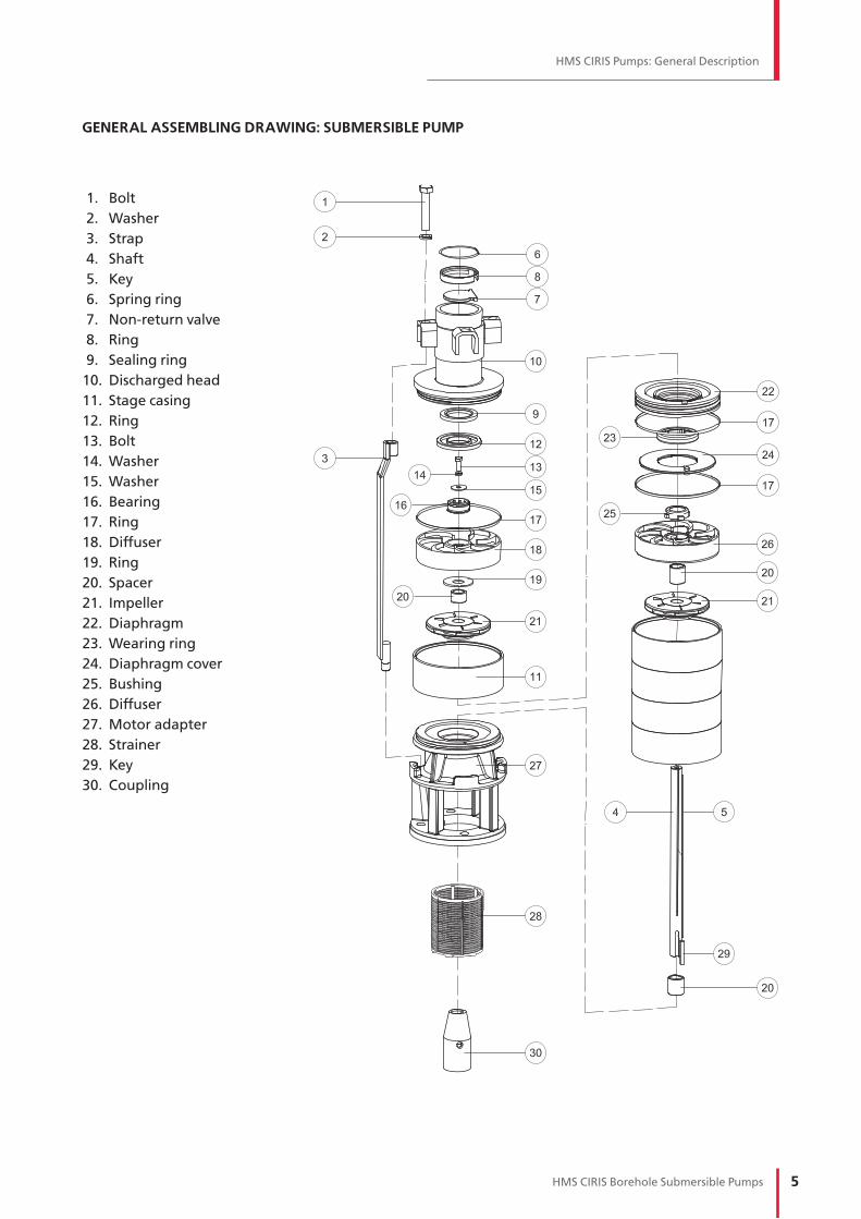
GENERAL ASSEMBLING DRAWING: SUBMERSIBLE PUMP
1. Bolt
2. Washer
3. Strap
4. Shaft
5. Key
6. Spring ring
7. Non-return valve
8. Ring
9. Sealing ring
10. Discharged head
11. Stage casing
12. Ring
13. Bolt
14. Washer
15. Washer
16. Bearing
17. Ring
18. Diffuser
19. Ring
20. Spacer
21. Impeller
22. Diaphragm
23. Wearing ring
24. Diaphragm cover
25. Bushing
26. Diffuser
27. Motor adapter
28. Strainer
29. Key
30. Coupling

6 HMS CIRIS Borehole Submersible Pumps
GENERAL ASSEMBLING DRAWING: SUBMERSIBLE MOTOR
1. Lockin ring
2. Diaphragm cover
3. Diaphragm
4. Screw
5. Washer
6. Bottom
7. Screw
8. Washer
9. Revers thrust bearing
10. O-ring
11. Lower bearing casing
12. Ring
13. Winding fixator
14. Sleeve bearing
15. Plug
16. O-ring
17. Upper bearing casing
18. Washer
19. Mechanical seal cover
20. Screw
21. Washer
22. Sand protector
23. Stud sealing
24. Mechanical seal
25. O-ring
26. Cable nut
27. Cable sealing
28. Cable sealing
29. Cable sealing
30. Stud
31. Lock ring
32. Thrust ring
33. Stator
34. Key
35. Rotor
36. Ring
37. Thrust journal
38. Thrust bearing
39. Screw
40. Lock nut
41. Screw
42. Key
43. Plate
HMS CIRIS Pumps: General Description

7HMS CIRIS Borehole Submersible Pumps
HMS CIRIS Pumps: General Description
MATERIAL SELECTION
Model
Pump Motor
Impeller Diffuser Stage casing Shaft Casing Bearing housing
CRS 6 – 4
Thermoplastic resin armored
with stainless
steel
Thermoplastic resin
AISI 316 AISI 420 AISI 316
Cast iron
with powder
coating
CRS 6 - 6.5
CRS 6 – 10
CRS 6 – 16
CRS 6 - 25
CRS 8 - 16
Thermoplastic resin armored
with stainless
steel
Thermoplastic resin
CRS 8 - 25Stainless steel;
AISI 316
Thermoplastic resin
CRS 8 - 40
CRS 8 - 65
Thermoplastic resin armored
with stainless
steel
Thermoplastic resin
CRS 10 - 65
AISI 316
Thermoplastic resin
CRS 10 - 100
AISI 316
CRS 10 - 120
CRS 10 - 160
CRS 12 - 160
CRS 12 - 200
CRS 12 - 210
CRS 12 - 250

8 HMS CIRIS Borehole Submersible Pumps
Pumps Selection and Operation Guideline
PUMP SELECTION AND OPERATION
GUIDELINE
The information in this section provides the
recommendations on selection, installation and
operation of the submersible pumps in the most
efficient way, avoiding the most typical mistakes
and significantly reducing the number of failures.
MAIN PARAMETERS
The water supply system consists of many
elements and the main of them are the pumps,
pipes, valves, tanks and reservoirs. Each element
influences on others so the whole system
efficiency and reliability depends on consistency
of its components operation (Fig. 1).
THE MAIN PARAMETERS OF THE PUMP
— Q-H curve to show head vs. capacity relation
— Q-P curve: power vs. capacity relationship
for multistage pumps the curve can be
shown for one stage or whole pump
— Efficiency curve to show stage efficiency
with taking into account losses in
non-return valve and at the pump inlet
H
QQoper. 1,2Qoper.0,7Qoper.
Hoper.
Hst
QQ oper. 1,2Q oper.0,7Q oper.
Ƞoper.
P oper.2
P2
Pump consumed power
Ƞ Pump efficiency
Head curve
Ƞ
P2
operation range
duty point
pump feature
system feature
Fig. 1. The pump and the water supply system parameters
9HMS CIRIS Borehole Submersible Pumps
Pumps Selection and Operation Guideline
1 - Borehole pump2 - Control panel3 - Pressure gauge4 - Valve5 - Open tank6 - Filter of well
1
2 3 4
6
1 m
Dynamic level
±0,00
Min
le
ve
l n
ot
less
1m
Н
Q
0
5
Efficiency curve
Pump feature
System featureНpump
Duty point
Performance range
Нst
ati
c
Нf
Нd
Нin
sta
ll
hf
Efficiency
Pump
efficiency
Static level
QQpump
Qpump
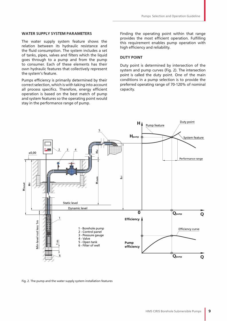
WATER SUPPLY SYSTEM PARAMETERS
The water supply system feature shows the
relation between its hydraulic resistance and
the fluid consumption. The system includes a set
of tanks, pipes, valves and filters which the liquid
goes through to a pump and from the pump
to consumer. Each of these elements has their
own hydraulic features that collectively represent
the system’s feature.
Pumps efficiency is primarily determined by their
correct selection, which is with taking into account
all process specifics. Therefore, energy efficient
operation is based on the best match of pump
and system features so the operating point would
stay in the performance range of pump.
Finding the operating point within that range
provides the most efficient operation. Fulfilling
this requirement enables pump operation with
high efficiency and reliability.
DUTY POINT
Duty point is determined by intersection of the
system and pump curves (Fig. 2). The intersection
point is called the duty point. One of the main
conditions in а pump selection is to provide the
preferred operating range of 70-120% of nominal
capacity.
Fig. 2. The pump and the water supply system installation features
10 HMS CIRIS Borehole Submersible Pumps
Pumps Selection and Operation Guideline
Initial data
— Required capacity and head values
— Well (borehole) data or ones got by measurement:
1. Internal well diameter (Tab. 1)
2. Static water level
3. Well yield (or output)
4. Dynamic water level (pumping water level)
to correspond with well yield
5. Well screen/filter depth
6. Chemical composition and solids content
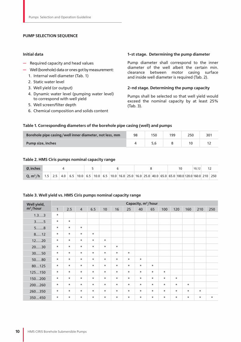
1-st stage. Determining the pump diameter
Pump diameter shall correspond to the inner
diameter of the well albeit the certain min.
clearance between motor casing surface
and inside well diameter is required (Tab. 2).
2-nd stage. Determining the pump capacity
Pumps shall be selected so that well yield would
exceed the nominal capacity by at least 25%
(Tab. 3).
PUMP SELECTION SEQUENCE
Table 1. Corresponding diameters of the borehole pipe casing (well) and pumps
Borehole pipe casing/well inner diameter, not less, mm 98 150 199 250 301
Pump size, inches 4 5,6 8 10 12
Table 2. HMS Ciris pumps nominal capacity range
O, inches 4 5 6 8 10 10,12 12
Q, m3/h 1.5 2.5 4.0 6.5 10.0 6.5 10.0 6.5 10.0 16.0 25.0 16.0 25.0 40.0 65.0 65.0 100.0 120.0 160.0 210 250
Table 3. Well yield vs. HMS Ciris pumps nominal capacity range
Well yield, m3/hour
Capacity, m3/hour
1 2.5 4 6.5 10 16 25 40 65 100 120 160 210 250
1.3….3 *
3…....5 * *
5…....8 * * *
8..…12 * * * *
12..…20 * * * * *
20..…30 * * * * * *
30..…50 * * * * * * *
50..…80 * * * * * * * *
80…125 * * * * * * * * *
125…150 * * * * * * * * * *
150…200 * * * * * * * * * * *
200…260 * * * * * * * * * * * *
260…350 * * * * * * * * * * * * *
350 ...450 * * * * * * * * * * * * * *

11HMS CIRIS Borehole Submersible Pumps
Pumps Selection and Operation Guideline
3-rd stage. Determining required pump head
Duty point is determined by the system
characteristic:
System characteristic consists of two parts: static
and dynamic heads.
Static head of system characteristic
According to installation position static part
is determined by geometric height of water lift
relative to dynamic water level and geometric
height of the tank. In case of operating with
accumulating tank or water collector the back
pressure must be taken into account.
Formula for the static part calculation:
where
Hdyn
– dynamic water level, m
Hgeo
– height from wellhead to max water
level in the tank, m
Pres
– pressure in the tank
– water density, kg/m3
g – acceleration of gravity, kg/m3
for a tank operating under atmospheric pressure
Formula for determining dynamic water level:
where
S – level lowering according to the spe-
cific well yield chart, m
Hst – static water level, m
Dynamic head of system characteristic
Dynamic head is determined by losses in the
pipeline and takes the form of quadratic
dependence: hf (Q) = k·Q2
where
k – loss coefficient that depends on losses
along the pipeline and elements resistances
(valves, manifolds, valves, adapters, etc.).
That relation is shown as parabola on chart.
Formula for head losses:
where
h100
– losses per every 100 m of a pipeline, m
L – actual pipeline length, m
h – elements loss value, m
Elements loss values according to flow rate are
given in Valve reference books and manuals.
h100
values for various material selection are
also given in reference materials. Data on losses
and flow rates in pipelines made of the most
common materials is given in Table 4 and Table 5.
(pp.13, 14).
Thus, by determining values of all system com-
ponents for various capacities, system’s head
characteristic can be built:
Knowing required head, in accordance with
1-3 stages it is possible to determine a pump
to comply with system features.

12 HMS CIRIS Borehole Submersible Pumps
Pumps Selection and Operation Guideline
Table 4. Head losses in steel pipes
Upper value: Flow rate, m/sec. Lower value: Losses per every 100 m of a straight steel pipe
Capacity Relative drift diameter/ outer diameter x wall thickness / internal diameter, mm
m3/h L/min L/secdN 25
33.5х3.227.1
dN 3242.3х3.2
35.9
dN 4048х3.5
41.0
dN 5060х3.5
53
dN 6576х3.5
69
dN 8089х3.5
82
dN 100108х3.5
101
dN 125133х4.5
124
dN 150159х4.5
150
dN 200219х5
209
1 16.67 0.280.481.91
0.270.48
0.210.25
1.6 26.67 0.440.774.63
0.441.14
0.340.59
0.200.17
2 33.33 0.560.967.08
0.551.73
0.420.90
0.250.25
2.5 41.67 0.691.20
10.850.692.63
0.531.36
0.310.38
0.190.11
3 50.00 0.831.44
15.400.823.72
0.631.91
0.380.54
0.220.15
3.5 58.33 0.971.69
20.740.964.99
0.742.56
0.440.71
0.260.19
0.180.08
4 66.67 1.111.93
26.861.106.44
0.843.30
0.500.91
0.300.25
0.210.11
6.5 108 1.813.13
69.251.78
16.391.378.34
0.822.28
0.480.61
0.340.26
0.230.09
8 133 2.223.85
104.102.20
24.541.68
12.451.013.39
0.590.90
0.420.38
0.280.14
0.180.05
10 167 2.78 2.74
37.922.1019.19
1.265.19
0.741.37
0.530.58
0.350.21
0.230.08
12 200 3.33 3.29
54.182.52
27.381.517.38
0.891.94
0.630.82
0.420.29
0.280.11
0.190.04
16 267 4.44 4.39
95.383.37
48.072.01
12.881.193.36
0.841.41
0.550.50
0.370.18
0.250.07
20 333 5.56 4.21
74.532.52
19.881.495.17
1.052.16
0.690.76
0.460.27
0.310.11
25 417 6.94 5.26
115.713.15
30.761.867.96
1.313.31
0.871.15
0.580.41
0.390.16
0.200.03
30 500 8.33 3.78
44.002.2311.34
1.584.70
1.041.63
0.690.58
0.470.23
0.240.04
35 583 9.72 4.41
59.592.60
15.321.846.33
1.212.19
0.810.78
0.550.30
0.280.06
40 667 11.11 5.04
77.532.97
19.892.108.20
1.392.84
0.921.01
0.630.39
0.320.07
50 833 13.89 6.30
120.483,71
30.802.63
12.681.734.36
1.151.54
0.790.59
0.400.11
65 1083 18.06 4.83
51.633.4221.19
2.257.26
1.502.55
1.020.97
0.530.18
80 1333 22.22 5.94
77.804.21
31.862.77
10.891.843.81
1.261.45
0.650.27
100 1667 27.78 7.43
120.995.26
49.473.4716.87
2.305.88
1.572.22
0.810.42
120 2000 33.33 6.31
70.924.16
24.132.768.39
1.893.17
0.970.59
140 2333 38.89 7.36
96.234.85
32.703.2211.35
2.204.27
1.130.79
160 2667 44.44 8.42
125.385.55
42.563.6814.75
2.525.54
1.301.02
180 3000 50.00 6.2453.71
4.1418.59
2.836.97
1.461.28
200 3333 55.56 6.93
66.164.60
22.873.148.57
1.621.57
220 3667 61.11 7.6379.91
5.0627.60
3.4610.33
1.781.89
240 4000 66.67 8.32
94.955.52
32.783.77
12.261.942.23
260 4333 72.22 9.01
111.295.98
38.394.09
14.352.112.61
280 4667 77.78 6.44
40.454.40
16.602.273.01
300 5000 83.33 6.90
50.964.72
19.022.433.45

13HMS CIRIS Borehole Submersible Pumps
Pumps Selection and Operation Guideline
Table 5. Head losses in plastic pipes
Upper value: Flow rate in m/sec. Lower value: Loss per every 100 m of a straight plastic pipe
Capacity Outer diameter x wall thickness / internal diameter, mm
m3/h L/min L/sec25x2.8
19.432x3.0
26.040x3.7
32.650x4.6
40.863x5.8
51.475x6.8
61.490x8.2
73.6110x10.0
90.0125x11.4
102.2140x12.7
114.6160x14.6
130.8180x16.4
147.2200x18.2
163.6
1 16.67 0.280.947.71
0.521.90
0.330.65
0.210.22
1.6 26.67 0.441.5017.74
0.844.38
0.531.49
0.340.51
0.210.17
2 33.33 0.561.88
26.361.056.51
0.672.21
0.420.76
0.270.25
0.190.11
2.5 41.67 0.692.3539.17
1.319.68
0.833.29
0.531.13
0.330.37
0.230.16
3 50.00 0.832.82
54.121.5713.37
1.004.54
0.641.56
0.400.52
0.280.22
0.200.09
3.5 58.33 0.973.2971.14
1.8317.58
1.165.97
0.742.05
0.470.68
0.330.29
0.230.12
4 66.67 1.113.76
90.162.09
22.281.337.57
0.852.59
0.540.86
0.38 0.37
0.260.16
0.170.06
6.5 108 1.816.11
213.343.40
52.722.1617.90
1.386.13
0.872.04
0.610.87
0.420.37
0.280.14
0.220.08
8 133 2.22 4.19
76.202.66
25.881.708.87
1.072.94
0.751.26
0.520.53
0.350.20
0.270.11
0.220.06
10 167 2.78 5.23
113.203.33
38.442.1213.17
1.344.37
0.941.87
0.650.79
0.440.30
0.340.16
0.270.10
0.210.05
12 200 3.33 6.28
156.433.99
53.122.55
18.201.616.04
1.132.59
0.781.09
0.520.42
0.410.23
0.320.13
0.250.07
0.200.04
16 267 4.44 5.32
88.503.40
30.322.1410.07
1.504.31
1.041.81
0.700.69
0.540.38
0.430.22
0.330.12
0.260.07
0.210.04
20 333 5.56 6.66
131.484.25
45.052.68
14.961.886.40
1.312.69
0.871.03
0.680.56
0.540.33
0.410.17
0.330.10
0.260.06
25 417 6.94 5.31
66.923.35
22.222.359.51
1.634.00
1.091.53
0.850.84
0.670.48
0.520.26
0.410.15
0.330.09
30 500 8.33 6.37
92.484.02
30.702.8113.14
1.965.53
1.312.12
1.021.15
0.810.67
0.620.36
0.490.20
0.400.12
35 583 9.72 7.44
121.574.69
40.363.2817.27
2.297.27
1.532.78
1.191.52
0.940.88
0.720.47
0.570.27
0.460.16
40 667 11.11 5.3551.15
3.7521.89
2.619.22
1.753.53
1.351.92
1.081.11
0.830.59
0.650.34
0.530.20
50 833 13.89 6.69
75.994.69
32.523.26
13.692.185.24
1.692.86
1.351.65
1.030.88
0.820.50
0.660.30
65 1083 18.06 8.70
121.036.10
51.804.2421.81
2.848.35
2.204.55
1.752.63
1.341.40
1.060.80
0.860.48
80 1333 22.22 7.51
74.875.22
31.523.49
12.062.716.57
2.153.81
1.652.02
1.311.15
1,060.70
100 1667 27.78 9.38
111.236.53
46.824.3717.92
3.399.77
2.695.65
2.073.01
1.631.71
1.321.03
120 2000 33.33 7.83
64.705.24
24.774.06
13.503.237.81
2.484.16
1.962.36
1.591.43
140 2333 38.89 9.14
85.056.11
32.554.7417.74
3.7710.27
2.895.46
2.293.11
1.851.88
160 2667 44.44 10.45
107.796.99
41.265.42
22.494.31
13.023.316.92
2.613.94
2.112.38
180 3000 50.00 7.86
50.846.1027.71
4.8516.04
3.728.53
2.944.86
2.382.93
200 3333 55.56 8.73
61.296.77
33.415.39
19.344.13
10.293.265.85
2.643.53
220 3667 61.11 9.61
72.587.45
39.565.92
22.904.5512.18
3.596.93
2.914.19
240 4000 66.67 10.4884.70
8.1346.16
6.4626.72
4.9614.21
3.928.09
3.174.88
260 4333 72.22 11.3597.62
8.8053.21
7.0030.80
5.3716.38
4.249.32
3.445.63
280 4667 77.78 12.23111.34
9.4860.68
7.5435.13
5.7918.69
4.5710.63
3.706.42
300 5000 83.33 10.1668.58
8.0839.70
6.2021.12
4.9012.02
3.967.26

14 HMS CIRIS Borehole Submersible Pumps
Pumps Selection and Operation Guideline
Hydraulic accumulator (pressure storage reservoir) installation in many cases prevents excessively frequent pump starts and reduces the water hammer impact. Hence, power consumption is optimized as well as pump operational life and head stability increase.
There are different methods of hydraulic accumulator selection. Many manufacturers of accumulators offer their own selection programs. Selecting hydraulic accumulator is a challenging task that requires taking into consideration many factors such as:
— Uneven water consumption
— Uneven water supply by pumps
— Control volume vs. Total tank volume
— Allowable number of pump starts per hour
Hydraulic accumulator selection based on UNI 9182 is given below with the main factors such as:
— Max pump capacity
— Recommended number of start/stop per hour
— Configuring pressure switch, i.e. setting cut-on and cut-off pressure values
— Initial pressure in the accumulator air chamber must be less than cut-on pressure at least by 0.5 bar
Pressure values are assumed in absolute terms. 1 bar is added to values received with pressure gauges. There is a formula below to define optimal volume of the hydraulic accumulator:
where
Vaccum
– hydraulic accumulator volume, liters
a – number of start/stop for pump, per hour
Qmax
– max. pump capacity, liters/min*
P(on) – cut-on pressure, bar
P(off) – cut-off pressure, bar
P(gas) – initial pressure in the accumulator air chamber, bar
The obtained value is rounded upwards to the nearest value of available hydraulic accumulator volume range.
HYDRAULIC ACCUMULATOR SELECTION
*1 liter/min = 0,06 m3/h

15HMS CIRIS Borehole Submersible Pumps
Pumps Selection and Operation Guideline
1
2 3 4
5
Hd
yn
Нin
stra
ll
±0,00
Нst
ati
c
Нg
eo
Нg
eo
Нg
eo
Нd
p tank
1 - Borehole pump2 - Control panel3 - Pressure gauge4 - Valve5 - Well filter
Dynamic level
Min
le
ve
l n
ot
less
1m
1 m
Fig. 3. Typical water intake options
If the required pump capacity is higher than
the borehole (well) yield then a dry running sensor
shall be applied. In this case the pump will operate
in a interrupted mode. Number of start/stop
per hour and interval between them shall be
taken into consideration accordingly to the pump
manual.
Possible well defects such as pipe misalignment,
poor quality of weld, well curvature may make
the pump installation difficult or even impossible.
Therefore, if there are doubts in well serviceability
a check-up of the corresponding diameters
is recommended before the pump installation.
Please follow the requirements of the pump
manual during installation.
For stable operation the pump suction strainer shall
be below dynamic water level at least by 1 meter.
The installation level must be measured from
the pump inlet. The motor bottom level must be
at least 1 m above the well filter. Failure to do
so carries the risk of large amount of sand ingress
and increased wear of the pump.
Discharge pipe diameter shall be equal to
discharge nozzle diameter or differ insignificantly.
It shall be noted that rising pipes with less inner
diameter have increased friction losses. Though
application of the rising pipes with increased
inner diameter is impractical due to higher cost
of the pipes. In selecting discharge pipe diameter
the liquid flow-rate shall remain within 1.5 - 3.0 m/s.
PUMP INSTALLATION REQUIREMENTS

16 HMS CIRIS Borehole Submersible Pumps
Pumps Selection and Operation Guideline
Example 1
Input data:
Water is supplied from the well into the water
tower located 20 m above the well. (Fig. 4).
Required pump capacity = 40 m3/h. Height
from the ground level to the top water level
in the water tower tank = 15 m. Water tower
is located 100 m away from the well. Static
water level in the well = 30 m. Level lowering
S = 10 m according to the specific yield chart
at 40 m3/h. Pipes are made of steel.
System characteristic calculation:
Dynamic water level will be at Hdyn = 40 m.
Proceeding from recommended flow-rate
1.5-3.0 m/sec we select dN 80 in the Table 4.
At Q=40 m3/h and dN 80 the flow rate will
approximately be 2.1 m/sec. According to the Table 4
the head loss will be 8.2 m per every 100 meters
of the pipeline. Total pipeline length with hori-
zontal and vertical sections will be 40+100 =140 m.
Therefore losses per length will be:
In accordance with the reference book head
losses of DN 80 valve is 0.09 m; head losses of pipe
bend DN 80 is 0.07 m. Dynamic head losses:
Static head will be:
Total system head will be:
If there are no other unaccounted losses then
pump with 86.8 m head would be needed.
PUMP SELECTION EXAMPLES
1
2 3 4
6
hstat
±0,00
20 m
15 m
5
1 - Borehole pump2 - Control panel3 - Pressure gauge4 - Valve5 - Water storage tower6 - Well filter
1 m
Min
le
ve
l n
ot
less
1m
Dynamic level
Нin
stra
ll
Hd
yn
Нst
ati
cН
ge
o
Fig. 4. Example 1

17HMS CIRIS Borehole Submersible Pumps
Pumps Selection and Operation Guideline
In the catalogue we select the pumps with the
max efficiency at this head value. On the head
curve we need to find the operating point
and the closest pump curve (Fig. 5).
In our case we would select CRS 8-40/6-15 pump.
At 40 m3/h capacity provides 90 m head.
80
70
60
50
40
30
20
10
520 44403632282420161284
320
300
280
260
240
220
200
180
160
140
120
100
80
60
40
20
520 44403632282420161284
η (%)
η
8-40/1
8-40/2
8-40/3
8-40/4
8-40/5
8-40/6
8-40/7
8-40/8
8-40/9
8-40/10
8-40/11
8-40/12
8-40/13
8-40/14
8-40/15
8-40/16 CRS 8-40
H, m
Q (m³/h)
Q (m³/h)
Fig. 5. HMS Ciris pump features

18 HMS CIRIS Borehole Submersible Pumps
Pumps Selection and Operation Guideline
Example 2
Input data:
Water is supplied from the well into hydraulic
accumulator (Fig. 6). Required capacity = 8 m3/h.
Static water level = 40 m. Level lowering S = 5 m
according to the specific yield chart at 8 m3/h.
Pressure switch shall provide:
— Cut-on pressure =1.8 bar
— Cut-off pressure = 4.5 bar
— Max. gas pressure in membrane = 1.5 bar
— Max. number of starts per hour = 6
PUMP SELECTION EXAMPLES
Hydraulic accumulator selection: according to UNI 9182 we get:
the closest volume will be = 1000 l.
System feature calculation:
Dynamic water level will be at hdyn= 45 m.
Proceeding from recommended flow-rate
1.5 - 3 m/s we need to select pipeline diameter
from the Table 5. As plastic pipeline has lower
hydraulic resistance than steel pipelines we
then can choose lower diameter, even lower
than pump outlet diameter. Proceeding from
recommended flow-rate 1.5 - 3 m/s we would
select D = 40.8 mm from the Table 5.
At Q = 8 m3/h and D=40.8 mm the flow-rate
will approximately make 1.7 m/s. According to
the Table 5 head loss will be 8.87 m per every
100 m of the pipeline. Pipeline length = 45 m.
Local losses are negligible compared to losses
per length at vertical section and also
compared to head and accumulator pressure.
If there are no other unaccounted losses then pump with 94.9 m head would be needed.

19HMS CIRIS Borehole Submersible Pumps
Pumps Selection and Operation Guideline
As in the previous example we need to select a pump
from the catalogue with maximum efficiency at
required head. By finding the operating point on
the head feature and the closest pump curve
we would select CRS 6-10/8-4 pump with 8 m3/h
capacity and 96 m head.
Fig. 6. Example 2
Discharge
1
2 3 4 5 6
7
Dynamic level
Нin
stra
ll
1 m
Min
le
ve
l n
ot
less
1m
Hd
yn
Нst
ati
c
1 - Borehole pump2 - Control panel3 - Pressure gauge4 - Pressure sensor5 - Valve
7 - filter of well6 - Hydraulic accumulator

20 HMS CIRIS Borehole Submersible Pumps
Pumps Selection and Operation Guideline
H st
atic
55%60%
65%70%
65%
20
DISCHARGE
40
60
80
0100 0 200 300 400 500
60%
n=2900 rpm
n=2800 rpmn=2700 rpm
System curve
Efficiency
SUCTION
Q, m3/h
H, m
55%60%
65%70%
65%
20
H st
atic
DISCHARGE
40
60
80
0100 0 200 300 400 500
60%
n=2900 rpm
n=2800 rpmn=2700 rpm
Efficiency
SUCTION
System curve
Q, m3/h
H, m
Pump operation with variable speed drives
has become very common recently though
it cannot always cut power consumption. Their
use would be most beneficial in systems
with dominant dynamic part, i.e. with friction
losses in pipelines and valves (Fig. 7).
Use of VSD in a system with predominant static
part (Fig. 8) leads to significant efficiency drop
if capacity changes.
In this case start / stop control of required number
of pumps installed in parallel connection would
be the most effective.
Therefore significant optimization of power
consumption lays within system feature and its
change over time.
OPERATION WITH VARIABLE SPEED DRIVES
Fig. 7. Pump operation in system with predominant friction losses in case of speed control
Fig. 8 Pump operation in system with predominant static part in case of speed control

21HMS CIRIS Borehole Submersible Pumps
Pumps Selection and Operation Guideline
BOREHOLE PUMPS OPERATION
WITH FREQUENCY INVERTERS
In operation with frequency inverters the following
requirements should be complied with:
— For efficient motor cooling the capacity
shall be at least 20% of nominal capacity
defined on Q-H curve. For example, CRS 6-10
nominal capacity = 8 m3/h. Pump usually
is controlled by pressure. Capacity may fall
below a specified level therefore the flow
sensor (switch) is recommended to be
installed to switch off the motor in case of
capacity drop below the operational range.
— Temperature sensor (to switch off motor
at temperature higher than 70 oC) is
recommended to be installed to protect
the motor winding from overheating,
blowing and breakdown.
— If a cable connecting the pump unit and
the inverter is quite long then the output
filters are recommended to be installed: dv/dt
filters or sine wave filters for reducing motor
insulation stress and protect from high voltage
pulses, premature wear and breakdown.
Recommendations of appropriate filters
installation should be checked with the
variable drive manufacturer.
In case of uneven water supply the frequency
inverter shall be applied used with hydraulic
accumulator or intermediate storage tank of
appropriate capacity cooling. Please bear in mind
that in case of large static part in the system
characteristic using of variable speed drives does
not result in energy efficiency, and only reduces
volume and dimensions of intermediate storage
tanks and risks of water hammer.
TYPICAL MISTAKES IN PUMP SELECTION AND
OPERATION
Frequent pumps failures and excessive power
consumption lays at the wrong pump selection
and unqualified maintenance during operation.
Most typical mistakes are listed below:
1. Pump installation and operation with overesti-
mated parameters (capacity, head) than required,
i.e. use of oversized pump that would cause
the unnecessarily high capital cost of equipment.
This problem may occur both at the construction
stage (Fig. 9-12) and during operation if system
features change.
The following below is typical in this case:
— real current consumption is significantly
higher than nominal
— frequent triggering of the control panels
under condition that control panel complies
with the pump parameters
— frequent pump starts/stops
Pump operation in that mode may lead to:
— higher water turbidity and sand content,
filter clogging and water quality deterioration
— increased power consumption at decreased
efficiency
— motor overheating
— motor winding breakdown
— wear resistance from floating impellers
Throttling control with valves leads to excessive
power loss due to friction.
2. Pump operation at a lower capacity results in:
— inadequate cooling and eventually motor
overheating
— increased wear of bearings due to insufficient
lubrication
— lower pump efficiency
3. Selection according to max capacity and head
Please bear in mind that besides operation at a max
efficiency there are other modes of operation.
Therefore the storage tanks installation and variable
pump control methods are recommended.

22 HMS CIRIS Borehole Submersible Pumps
Pumps Selection and Operation Guideline
Operation range
Operation range
Operation rangeOperation
range
Pump curve
Pump curve
Head Head
Head
Efficiency
Efficiency
Head
Q1 Q2
Excessive head pump
Required duty point
Required duty point
Required pump
Required pump
Required duty point
Required duty point
Estimated system curve
Estimated system curve
Actual system curve
Actual system curve
Actualduty point
Actual duty point
Actualduty point
Actualduty point
Q1 Q2
Power
Power
Q1 Q2
Capacity
Capacity
Capacity Capacity
Capacity Capacity
Capacity
CapacityQ1 Q2
Q2 Q1
Q2 Q1
Deficient head pump
Q2 Q1
Q2 Q1
Fig. 9. Pump operation with excessive head
Fig.11. Pump operation at a higher capacity
Fig.10. Pump operation with deficient head
Fig.12. Pump operation at a lower capacity

23HMS CIRIS Borehole Submersible Pumps
Pumps Selection and Operation Guideline
4. Pump operation without cooling shroud in a
well of larger diameter
Installation of a pump of lower diameter in
respect to diameter of the well reduces significantly
the liquid flow rate required for the motor cooling
and leads to overheating and shortened
operational life.
The pump diameter should be selected in a way
to keep the liquid velocity at least 0.2 m/s.
where
D – well diameter, m
d – pump diameter, m
Q – pump capacity, m3/h
v – average liquid velocity, m/s
Pump diameter is selected according to required capacity:
5. Pipe selection of lower diameter
Use of pipes of lower diameter than size of discharge
nozzle (thread or flanged) for saving purpose
results in major loss due to friction and increase
of required head. The required liquid flow
presumably could not be reached at that.
6. Cable selection of smaller cross-section
Selecting cross-section lower than recommended
will lead to significant voltage drop which would
affect the motor and cause overheating.
7. Pump capacity exceeds well yield. That leads
to dry running operation, which will cause:
— motor overheating
— rapid wear of bearings
— increased corrosion
8. Poor quality of supply voltage and absence
of control panels
Direct connection to the power supply does not
help to protect the motor from the most typical
causes of failure such as current unbalance,
phase reversal, under/overvoltage, etc.
9. Built-in non-return valve dismantling
Leads to pump parts experiencing water hammer
when pump stops. Besides, after each start
the pump is running to fill the pipeline.
10. Absence of instrumentation
Instrumentation and sensors (water level, pres-
sure, flow rate, voltage, current, number
of starts/stops and time of pump operation, etc.)
provide valid data on the pump operation
and system features for monitoring and timely
intervention into pump operation.
flow direction
min.velocity:V=0.2 m/s
S=π(D²-d²)/4
A
A
dD

24 HMS CIRIS Borehole Submersible Pumps
Performance Curves and Dimensions
PERFORMANCE CURVES AND DIMENSIONS
Performance curves are given according to
ISO 9906:1999, Appendix А for the following
conditions:
— rated rotation speed
— voltage supply frequency: 50 Hz
— pumped liquid: clean fresh water
— water temperature: +20°С
— kinematic viscosity: 1·10-6 m2/s (1cSt )
Hydraulic losses in non-return valve are taken into
account.
Performance curves are given for one pump stage
as well as power curves.
where
P2_stg
– stage power, kW
P2_pump
– pump shaft power, kW
n – number of stages
It is recommended to select a pump according to operation at max efficiency within 0.6 - 1.2 capacity range.
Delivery status (indicated in table):
«+» - in storage. Empty field – model available on request.
CRS 6-4
CRS 6-6,5
CRS 6-10
õ õ õ õ õ
õ õ õ õ õ
õ õ õ õ õ
õ õ õõ
õ õ õ õ õ õ õ
õ õ õ
õ õ
õ õ õ
õ õ
õõ õ
õ õ õ
CRS 6-16
CRS 6-25
õ õ õ õ õ
õ õ õ õ õ
õ õ õ õ õ
õõ õ õ
õ
õ õ õ õ õ õ õ
õ õ õ
õ õ
õ õ õ
õ õ
õõ õ
õ õ õ
CRS 8-16
CRS 8-25
CRS 8-40 CRS 8-65
CRS 10-65 CRS 10-160
CRS 10-100
CRS 10-120
CRS 12-250
CRS 12-210
CRS 12-200
CRS 12-160

25HMS CIRIS Borehole Submersible Pumps
Performance Curves and Dimensions
Pump
Electric motor Dimensions, mmWeight,
kgDelivery
status Type Power, kW D L A B G
CRS 6-4/6-3 DAP 6-3 3 144 1070 473 597
G2
” –
B G
OS
T 6
35
7 s
tan
da
rd
57 +
CRS 6-4/7-3 DAP 6-3 3 144 1115 518 597 60
CRS 6-4/8-3 DAP 6-3 3 144 1155 558 597 62
CRS 6-4/9-3 DAP 6-3 3 144 1200 603 597 64 +
CRS 6-4/10-3 DAP 6-3 3 144 1240 643 597 67
CRS 6-4/11-4 DAP 6-4 4 144 1270 649 621 69 +
CRS 6-4/12-4 DAP 6-4 4 144 1310 689 621 71
CRS 6-4/13-4 DAP 6-4 4 144 1355 734 621 73
CRS 6-4/14-4 DAP 6-4 4 144 1395 774 621 74 +
CRS 6-4/15-4 DAP 6-4 4 144 1440 819 621 75
CRS 6-4/16-4 DAP 6-4 4 144 1480 859 621 76 +
HMS CIRIS 6-4
L
A
D
G
B
õ õ õ õ õ
õ õ õ õ õ
õ õ õ õ õ
õ õ õõ
õ õ õ õ õ õ õ
õ õ õ
õ õ
õ õ õ
õ õ
õ õ õ
õ õ õ

26 HMS CIRIS Borehole Submersible Pumps
Performance Curves and Dimensions
10
20
30
40
50
60
70
220
200
180
160
140
120
100
80
60
40
20
η (%)
0.05
0.10
0.15
0.20
0.25
0.30
0.35
0.40η
0 654.540.5 1 1.5 2 2.5 3 3.5
0.20 0.4 0.6 0.8 1.0 1.2 1.4 1.6
0 654.540.5 1 1.5 2 2.5 3 3.5
0.20 0.4 0.6 0.8 1.0 1.2.
1.4 1.6
6-4/6
6-4/9
6-4/11
6-4/14
6-4/16
6-4/7
6-4/8
6-4/10
6-4/12
6-4/13
6-4/15
CRS 6-4
H (m)
P2
P2 (kW)
Q (m³/h)
Q (l/s)
Q (m³/h)
Q (l/s)

27HMS CIRIS Borehole Submersible Pumps
Performance Curves and Dimensions
HMS CIRIS 6-6.5
PumpElectric motor Dimensions, mm
Weight, kg
Delivery status
Type Power, kW D L A B G
CRS 6-6.5/6-3 DAP 6-3 3 144 1075 478 597
G2
” –
B G
OS
T 6
35
7 s
tan
da
rd
62 +
CRS 6-6.5/7-3 DAP 6-3 3 144 1125 528 597 63
CRS 6-6.5/8-3 DAP 6-3 3 144 1170 573 597 64 +
CRS 6-6.5/9-4 DAP 6-4 4 144 1230 609 621 66 +
CRS 6-6.5/10-4 DAP 6-4 4 144 1270 649 621 67
CRS 6-6.5/11-4 DAP 6-4 4 144 1310 689 621 68 +
CRS 6-6.5/12-5.5 DAP 6-5.5 5.5 144 1410 769 641 74 +
CRS 6-6.5/13-5.5 DAP 6-5.5 5.5 144 1420 779 641 75
CRS 6-6.5/14-5.5 DAP 6-5.5 5.5 144 1430 789 641 75 +
CRS 6-6.5/15-7.5 DAP 6-7.5 7.5 144 1540 834 706 84
CRS 6-6.5/16-7.5 DAP 6-7.5 7.5 144 1590 884 706 85 +
CRS 6-6.5/17-7.5 DAP 6-7.5 7.5 144 1640 934 706 86
CRS 6-6.5/18-7.5 DAP 6-7.5 7.5 144 1690 984 706 88
CRS 6-6.5/19-7.5 DAP 6-7.5 7.5 144 1740 1034 706 89 +
CRS 6-6.5/20-9 DAP 6-9 9 144 1790 1059 731 90
CRS 6-6.5/21-9 DAP 6-9 9 144 1840 1109 731 91
CRS 6-6.5/22-11 DAP 6-11 11 144 1890 1124 766 92
CRS 6-6.5/23-11 DAP 6-11 11 144 1940 1174 766 94
CRS 6-6.5/24-11 DAP 6-11 11 144 1990 1224 766 95
CRS 6-6.5/25-11 DAP 6-11 11 144 2040 1274 766 96
CRS 6-6.5/26-13 DAP 6-13 13 144 2090 1269 821 97
CRS 6-6.5/27-13 DAP 6-13 13 144 2140 1319 821 98
L
A
D
G
B
õ õ õ õ õ
õ õ õ õ õ
õ õ õ õ õ
õ õ õõ
õ õ õ õ õ õ õ
õ õ õ
õ õ
õ õ õ
õ õ
õ õ õ
õ õ õ

28 HMS CIRIS Borehole Submersible Pumps
Performance Curves and Dimensions
350
10
20
30
40
50
60
70
300
250
200
150
100
50
η (%)
0.10
0.15
0.20
0.25
0.30
0.35
0.40
η 0.45
10876543210
0 1.00.2 0.4 0.6 0.8 2.01.2 1.4 1.6 1.8 2.2 2.8
10876543210
0 1.00.2 0.4 0.6 0.8 2.01.2 1.4 1.6 1.8 2.2 2.8
6-6.5/6
6-6.5/7
6-6.5/8
6-6.5/9
6-6.5/11
6-6.5/12
6-6.5/14
6-6.5/16
6-6.5/17
6-6.5/19
6-6.5/21
6-6.5/23
6-6.5/25
6-6.5/27
6-6.5/10
6-6.5/13
6-6.5/15
6-6.5/18
6-6.5/20
6-6.5/22
6-6.5/24
6-6.5/26 CRS 6-6.5
P2
H (m)
P2 (kW)
Q (m³/h)
Q (l/s)
Q (m³/h)
Q (l/s)

29HMS CIRIS Borehole Submersible Pumps
Performance Curves and Dimensions
PumpElectric motor Dimensions, mm Weight,
kgDelivery
statusType Power, kW D L A B G
CRS 6-10/2-3 DAP 6-3 3 144 930 333 597
G2
” –
B G
OS
T 6
35
7 s
tan
da
rd
57
CRS 6-10/3-3 DAP 6-3 3 144 970 373 597 58
CRS 6-10/4-3 DAP 6-3 3 144 1010 413 597 59
CRS 6-10/5-3 DAP 6-3 3 144 1050 453 597 60 +
CRS 6-10/6-3 DAP 6-3 3 144 1090 493 597 61
CRS 6-10/7-4 DAP 6-4 4 144 1150 529 621 64 +
CRS 6-10/8-4 DAP 6-4 4 144 1190 569 621 65
CRS 6-10/9-5.5 DAP 6-5.5 5.5 144 1250 609 641 68
CRS 6-10/10-5.5 DAP 6-5.5 5.5 144 1320 679 641 69 +
CRS 6-10/11-5.5 DAP 6-5.5 5.5 144 1335 694 641 70 +
CRS 6-10/12-7.5 DAP 6-7.5 7.5 144 1435 729 706 79
CRS 6-10/13-7.5 DAP 6-7.5 7.5 144 1470 764 706 80 +
CRS 6-10/14-7.5 DAP 6-7.5 7.5 144 1515 809 706 81
CRS 6-10/15-9 DAP 6-9 9 144 1580 849 731 84 +
CRS 6-10/16-9 DAP 6-9 9 144 1620 889 731 85
CRS 6-10/17-9 DAP 6-9 9 144 1660 929 731 86 +
CRS 6-10/18-9 DAP 6-9 9 144 1700 969 731 87
CRS 6-10/19-11 DAP 6-11 11 144 1770 1004 766 92
CRS 6-10/20-11 DAP 6-11 11 144 1810 1044 766 93
CRS 6-10/21-11 DAP 6-11 11 144 1850 1084 766 94
CRS 6-10/22-11 DAP 6-11 11 144 1890 1124 766 95 +
CRS 6-10/23-13 DAP 6-13 13 144 1990 1169 821 101
CRS 6-10/24-13 DAP 6-13 13 144 2025 1204 821 102
CRS 6-10/25-13 DAP 6-13 13 144 2065 1244 821 103
CRS 6-10/26-13 DAP 6-13 13 144 2105 1284 821 104
CRS 6-10/27-13 DAP 6-13 13 144 2145 1324 821 105 +
CRS 6-10/28-15 DAP 6-15 15 144 2225 1364 861 110
CRS 6-10/29-15 DAP 6-15 15 144 2265 1404 861 111
CRS 6-10/30-15 DAP 6-15 15 144 2305 1444 861 112
CRS 6-10/31-15 DAP 6-15 15 144 2345 1484 861 113
CRS 6-10/32-15 DAP 6-15 15 144 2385 1524 861 114 +
CRS 6-10/33-18.5 DAP 6-18.5 18.5 144 2470 1564 906 120
CRS 6-10/34-18.5 DAP 6-18.5 18.5 144 2510 1604 906 121
CRS 6-10/35-18.5 DAP 6-18.5 18.5 144 2550 1644 906 122
CRS 6-10/36-18.5 DAP 6-18.5 18.5 144 2590 1684 906 123
CRS 6-10/37-18.5 DAP 6-18.5 18.5 144 2630 1724 906 124
HMS CIRIS 6-10
L
A
D
G
B
õ õ õ õ õ
õ õ õ õ õ
õ õ õ õ õ
õ õ õõ
õ õ õ õ õ õ õ
õ õ õ
õ õ
õ õ õ
õ õ
õ õ õ
õ õ õ

30 HMS CIRIS Borehole Submersible Pumps
Performance Curves and Dimensions
240
80
220
200
180
160
140
120
100
80
60
40
20
70
60
50
40
30
20
10
η (%)
0.50
0.45
0.40
0.35
0.30
0.25
0.20
0.55
0.60η
0 1513121110987654321
0 1.00.2 0.4 0.6 0.8 2.01.2 1.4 1.6 1.8 3.02.2 2.4 2.6 2.8 3.2 3.4 3.6 4.2
0 1513121110987654321
0 1.00.2 0.4 0.6 0.8 2.01.2 1.4 1.6 1.8 3.02.2 2.4 2.6 2.8 3.2 3.4 3.6 4.2
6-10/5
6-10/7
6-10/10
6-10/4
6-10/3
6-10/2
6-10/6
6-10/8
6-10/9
CRS 6-10
6-10/11
6-10/13
6-10/15
6-10/17
6-10/12
6-10/14
6-10/16
6-10/186-10/19
P2
H (m)
P2 (kW)
Q (m³/h)
Q (l/s)
Q (m³/h)
Q (l/s)

31HMS CIRIS Borehole Submersible Pumps
Performance Curves and Dimensions
450
150
450
170
190
210
230
250
270
290
310
330
350
370
390
410
430
80
70
60
50
40
30
20
10
η (%)
0.50
0.45
0.40
0.35
0.30
0.25
0.20
0.55
0.60η
0 1513121110987654321
0 1.00.2 0.4 0.6 0.8 2.01.2 1.4 1.6 1.8 3.02.2 2.4 2.6 2.8 3.2 3.4 3.6 4.2
0 1513121110987654321
0 1.00.2 0.4 0.6 0.8 2.01.2 1.4 1.6 1.8 3.02.2 2.4 2.6 2.8 3.2 3.4 3.6 4.2
6-10/20
6-10/21
6-10/226-10/23
6-10/24
6-10/26
6-10/276-10/286-10/29
6-10/30
6-10/31
6-10/326-10/336-10/346-10/356-10/366-10/37
6-10/25
CRS 6-10
P2
H (m)
P2 (kW)
Q (m³/h)
Q (l/s)
Q (m³/h)
Q (l/s)

32 HMS CIRIS Borehole Submersible Pumps
Performance Curves and Dimensions
HMS CIRIS 6-16
PumpElectric motor Dimensions, mm Weight,
kgDelivery
statusType Power, kW D L A B G
CRS 6-16/2-3 DAP 6-3 3 144 1000 403 597
G 2
1/ 2
“ –
В G
OS
T 6
35
7 s
tan
da
rt
64
CRS 6-16/3-3 DAP 6-3 3 144 1050 453 597 65
CRS 6-16/4-3 DAP 6-3 3 144 1100 503 597 66
CRS 6-16/5-3 DAP 6-3 3 144 1150 553 597 67
CRS 6-16/6-3 DAP 6-3 3 144 1200 603 597 68 +
CRS 6-16/7-4 DAP 6-4 4 144 1270 649 621 70
CRS 6-16/8-5.5 DAP 6-5.5 5.5 144 1340 699 641 73
CRS 6-16/9-5.5 DAP 6-5.5 5.5 144 1420 714 706 80 +
CRS 6-16/10-7.5 DAP 6-7.5 7.5 144 1430 724 706 73 +
CRS 6-16/11-7.5 DAP 6-7.5 7.5 144 1520 814 706 86 +
CRS 6-16/12-7.5 DAP 6-7.5 7.5 144 1570 864 706 87
CRS 6-16/13-7.5 DAP 6-7.5 7.5 144 1620 914 706 88 +
CRS 6-16/14-9 DAP 6-9 9 144 1690 959 731 91
CRS 6-16/15-9 DAP 6-9 9 144 1730 999 731 92
CRS 6-16/16-11 DAP 6-11 11 144 1830 1064 766 97 +
CRS 6-16/17-13 DAP 6-13 13 144 1940 1119 821 103 +
CRS 6-16/18-13 DAP 6-13 13 144 1970 1149 821 104
CRS 6-16/19-13 DAP 6-13 13 144 2000 1179 821 105
CRS 6-16/20-13 DAP 6-13 13 144 2030 1209 821 106
CRS 6-16/21-15 DAP 6-15 15 144 2090 1229 861 111 +
CRS 6-16/22-15 DAP 6-15 15 144 2135 1274 861 112
CRS 6-16/23-15 DAP 6-15 15 144 2180 1319 861 113
CRS 6-16/24-15 DAP 6-15 15 144 2220 1359 861 114
CRS 6-16/25-18.5 DAP 6-18.5 18.5 144 2310 1404 906 120
CRS 6-16/26-18.5 DAP 6-18.5 18.5 144 2350 1444 906 121
CRS 6-16/27-18.5 DAP 6-18.5 18.5 144 2395 1489 906 122
CRS 6-16/28-18.5 DAP 6-18.5 18.5 144 2440 1534 906 123
CRS 6-16/29-18.5 DAP 6-18.5 18.5 144 2480 1574 906 124
CRS 6-16/30-18.5 DAP 6-18.5 18.5 144 2520 1614 906 125
L
A
D
G
B
õ õ õ õ õ
õ õ õ õ õ
õ õ õ õ õ
õõ õ õ
õ
õ õ õ õ õ õ õ
õ õ õ
õ õ
õ õ õ
õ õ
õ õ õ
õ õ õ

33HMS CIRIS Borehole Submersible Pumps
Performance Curves and Dimensions
80
70
60
50
40
30
20
10
22
180
18161412108642
160
140
120
100
80
60
40
20
η (%)
0.50
0.45
0.40
0.35
0.30
0.55
0.60
0.65
0.70η
0
0 1.00.5 2.01.5 3.02.5 4.03.5 5.04.5 6.0
22181614121086420
0 1.00.5 2.01.5 3.02.5 4.03.5 5.04.5 6.0
6-16/2
6-16/3
6-16/4
6-16/5
6-16/6
6-16/7
6-16/8
6-16/9
6-16/10
6-16/11
6-16/12
6-16/13
6-16/14
6-16/15
6-16/16
CRS 6-16
P2
Q (m³/h)
H (m)
P2 (kW)Q (l/s)
Q (m³/h)
Q (l/s)

34 HMS CIRIS Borehole Submersible Pumps
Performance Curves and Dimensions
320
300
280
260
240
220
200
180
160
140
120
100
80
70
60
50
40
30
20
10
η (%)
0.50
0.45
0.40
0.35
0.30
0.55
0.60
0.65
0.70η
22181614121086420
0 1.00.5 2.01.5 3.02.5 4.03.5 5.04.5 6.0
22181614121086420
0 1.00.5 2.01.5 3.02.5 4.03.5 5.04.5 6.0
6-16/176-16/186-16/19
6-16/20
6-16/216-16/22
6-16/23
6-16/24
6-16/25
6-16/26
6-16/27
6-16/28
6-16/29
6-16/30CRS 6-16
P2
H (m)
P2 (kW)
Q (m³/h)
Q (l/s)
Q (m³/h)
Q (l/s)

35HMS CIRIS Borehole Submersible Pumps
Performance Curves and Dimensions
HMS CIRIS 6-25
PumpElectric motor Dimensions, mm Weight,
kgDelivery
statusType Power, kW D L A B G
CRS 6-25/2-3 DAP 6-3 3 144 970 373 597
SP
-89
-D G
OS
T 6
33
sta
nd
ard
- s
ee
ad
ap
tors
p.p
. 5
7-5
8
64
CRS 6-25/3-3 DAP 6-3 3 144 1020 423 597 65
CRS 6-25/4-3 DAP 6-3 3 144 1070 473 597 66
CRS 6-25/5-4 DAP 6-4 4 144 1150 529 621 70
CRS 6-25/6-5.5 DAP 6-5.5 5.5 144 1220 579 641 73 +
CRS 6-25/8-7.5 DAP 6-7.5 7.5 144 1400 694 706 81 +
CRS 6-25/9-7.5 DAP 6-7.5 7.5 144 1460 754 706 82 +
CRS 6-25/10-7.5 DAP 6-7.5 7.5 144 1500 794 706 84 +
CRS 6-25/11-9 DAP 6-9 9 144 1570 839 731 87 +
CRS 6-25/13-11 DAP 6-11 11 144 1750 984 766 93 +
CRS 6-25/14-11 DAP 6-11 11 144 1800 1034 766 94
CRS 6-25/15-13 DAP 6-13 13 144 1870 1049 821 101 +
CRS 6-25/16-13 DAP 6-13 13 144 1920 1099 821 103
CRS 6-25/17-15 DAP 6-15 15 144 2010 1149 861 108 +
CRS 6-25/18-15 DAP 6-15 15 144 2060 1199 861 110
CRS 6-25/19-15 DAP 6-15 15 144 2110 1249 861 111
CRS 6-25/20-18.5 DAP 6-18.5 18.5 144 2210 1304 906 117 +
CRS 6-25/21-18.5 DAP 6-18.5 18.5 144 2260 1354 906 119
CRS 6-25/22-18.5 DAP 6-18.5 18.5 144 2310 1404 906 120
CRS 6-25/23-18.5 DAP 6-18.5 18.5 144 2360 1454 906 121
L
A
D
G
B
õ õ õ õ õ
õ õ õ õ õ
õ õ õ õ õ
õõ õ õ
õ
õ õ õ õ õ õ õ
õ õ õ
õ õ
õ õ õ
õ õ
õ õ õ
õ õ õ
36 HMS CIRIS Borehole Submersible Pumps
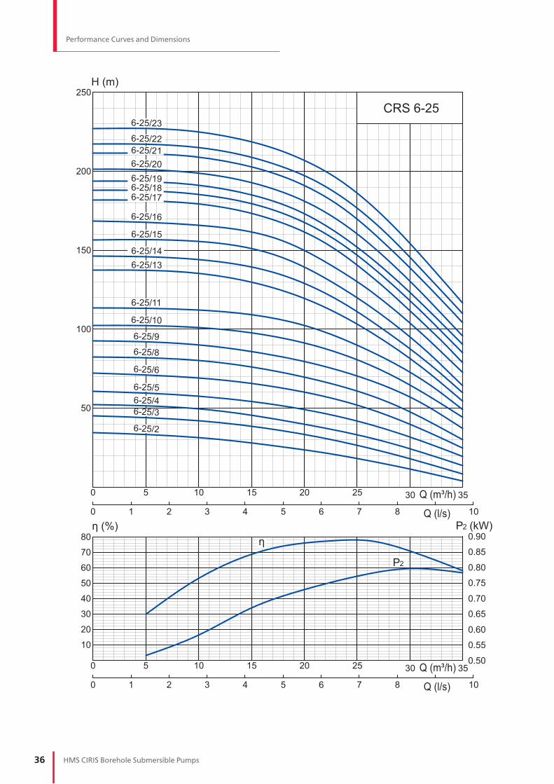
Performance Curves and Dimensions
35
250
80
70
60
50
40
30
20
10
30252015105
200
150
100
50
η (%)
0.50
0.55
0.60
0.65
0.70
0.75
0.80
0.85
0.90η
0
0 1 2 3 4 5 6 7 8 10
35302520151050
0 1 2 3 4 5 6 7 8 10
6-25/2
6-25/36-25/46-25/5
6-25/6
6-25/8
6-25/9
6-25/10
6-25/11
6-25/136-25/14
6-25/15
6-25/16
6-25/176-25/186-25/19
6-25/206-25/216-25/22
6-25/23CRS 6-25
P2
Q (m³/h)
H (m)
P2 (kW)Q (l/s)
Q (m³/h)
Q (l/s)
37HMS CIRIS Borehole Submersible Pumps
Performance Curves and Dimensions
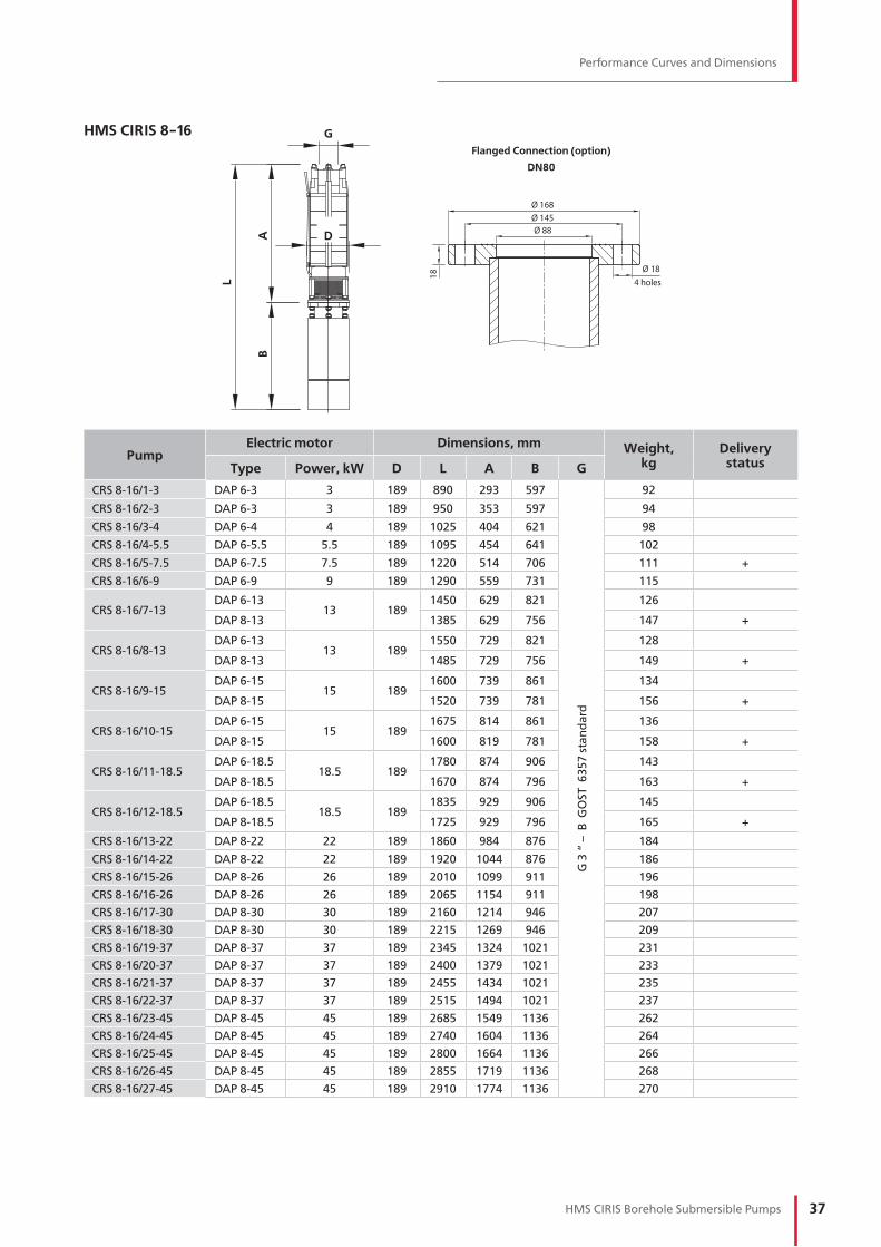
HMS CIRIS 8-16
PumpElectric motor Dimensions, mm Weight,
kgDelivery
statusType Power, kW D L A B G
CRS 8-16/1-3 DAP 6-3 3 189 890 293 597
G 3
“ –
B G
OS
T 6
35
7 s
tan
da
rd
92
CRS 8-16/2-3 DAP 6-3 3 189 950 353 597 94
CRS 8-16/3-4 DAP 6-4 4 189 1025 404 621 98
CRS 8-16/4-5.5 DAP 6-5.5 5.5 189 1095 454 641 102
CRS 8-16/5-7.5 DAP 6-7.5 7.5 189 1220 514 706 111 +
CRS 8-16/6-9 DAP 6-9 9 189 1290 559 731 115
CRS 8-16/7-13DAP 6-13
13 1891450 629 821 126
DAP 8-13 1385 629 756 147 +
CRS 8-16/8-13DAP 6-13
13 1891550 729 821 128
DAP 8-13 1485 729 756 149 +
CRS 8-16/9-15DAP 6-15
15 1891600 739 861 134
DAP 8-15 1520 739 781 156 +
CRS 8-16/10-15DAP 6-15
15 1891675 814 861 136
DAP 8-15 1600 819 781 158 +
CRS 8-16/11-18.5DAP 6-18.5
18.5 1891780 874 906 143
DAP 8-18.5 1670 874 796 163 +
CRS 8-16/12-18.5DAP 6-18.5
18.5 1891835 929 906 145
DAP 8-18.5 1725 929 796 165 +
CRS 8-16/13-22 DAP 8-22 22 189 1860 984 876 184
CRS 8-16/14-22 DAP 8-22 22 189 1920 1044 876 186
CRS 8-16/15-26 DAP 8-26 26 189 2010 1099 911 196
CRS 8-16/16-26 DAP 8-26 26 189 2065 1154 911 198
CRS 8-16/17-30 DAP 8-30 30 189 2160 1214 946 207
CRS 8-16/18-30 DAP 8-30 30 189 2215 1269 946 209
CRS 8-16/19-37 DAP 8-37 37 189 2345 1324 1021 231
CRS 8-16/20-37 DAP 8-37 37 189 2400 1379 1021 233
CRS 8-16/21-37 DAP 8-37 37 189 2455 1434 1021 235
CRS 8-16/22-37 DAP 8-37 37 189 2515 1494 1021 237
CRS 8-16/23-45 DAP 8-45 45 189 2685 1549 1136 262
CRS 8-16/24-45 DAP 8-45 45 189 2740 1604 1136 264
CRS 8-16/25-45 DAP 8-45 45 189 2800 1664 1136 266
CRS 8-16/26-45 DAP 8-45 45 189 2855 1719 1136 268
CRS 8-16/27-45 DAP 8-45 45 189 2910 1774 1136 270
L
A D
G
B
Ø 168Ø 145Ø 88
Ø 18
18
4 holes
Flanged Connection (option)
DN80

38 HMS CIRIS Borehole Submersible Pumps
Performance Curves and Dimensions
80
70
60
50
40
30
20
10
350
300
250
200
150
100
50
η (%)
0.60
0.70
0.80
0.90
1.00
1.10
1.20
1.30
1.40η
22181614121086420
0 1.00.5 2.01.5 3.02.5 4.03.5 5.04.5 6.0
22181614121086420
0 1.00.5 2.01.5 3.02.5 4.03.5 5.04.5 6.0
8-16/1
8-16/2
8-16/3
8-16/4
8-16/5
8-16/6
8-16/7
8-16/8
8-16/9
8-16/10
8-16/11
8-16/12
8-16/13
CRS 8-16
P2
H (m)
P2 (kW)
Q (m³/h)
Q (l/s)
Q (m³/h)
Q (l/s)

39HMS CIRIS Borehole Submersible Pumps
Performance Curves and Dimensions
320
300
280
260
240
220
200
180
160
140
120
100
80
70
60
50
40
30
20
10
η (%)
0.50
0.45
0.40
0.35
0.30
0.55
0.60
0.65
0.70η
22181614121086420
0 1.00.5 2.01.5 3.02.5 4.03.5 5.04.5 6.0
22181614121086420
0 1.00.5 2.01.5 3.02.5 4.03.5 5.04.5 6.0
6-16/176-16/186-16/19
6-16/20
6-16/216-16/22
6-16/23
6-16/24
6-16/25
6-16/26
6-16/27
6-16/28
6-16/29
6-16/30CRS 6-16
P2
H (m)
P2 (kW)
Q (m³/h)
Q (l/s)
Q (m³/h)
Q (l/s)

40 HMS CIRIS Borehole Submersible Pumps
Performance Curves and Dimensions
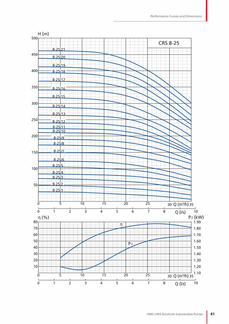
HMS CIRIS 8-25
PumpElectric motor Dimensions, mm Weight,
kgDelivery
statusType Power, kW D L A B G
CRS 8-25/1-3 DAP 6-3 3 189 915 318 597
G 3
“ –
B G
OS
T 6
35
7 s
tan
da
rd
90
CRS 8-25/2-4 DAP 6-4 4 189 995 374 621 94
CRS 8-25/3-5.5 DAP 6-5.5 5.5 189 1070 429 641 98 +
CRS 8-25/4-7.5 DAP 6-7.5 7.5 189 1190 484 706 107 +
CRS 8-25/5-9 DAP 6-9 9 189 1270 539 731 111
CRS 8-25/6-11 DAP 6-11 11 189 1360 594 766 117 +
CRS 8-25/7-13 DAP 6-13 13 189 1481 660 821 124 +
CRS 8-25/8-15DAP 6-15
15 1891570 709 861 130
DAP 8-15 1490 709 781 152 +
CRS 8-25/9-18.5DAP 6-18.5
18.5 1891680 774 906 137
DAP 8-18.5 1570 774 796 157
CRS 8-25/10-18.5DAP 6-18.5
18.5 1891730 824 906 139
DAP 8-18.5 1620 824 796 159 +
CRS 8-25/11-22 DAP 8-22 22 189 1760 884 876 178
CRS 8-25/12-22 DAP 8-22 22 189 1820 944 876 180
CRS 8-25/13-22 DAP 8-22 22 189 1895 989 876 182 +
CRS 8-25/14-30 DAP 8-30 30 189 2140 1194 946 199
CRS 8-25/15-30 DAP 8-30 30 189 2195 1249 946 201
CRS 8-25/16-30 DAP 8-30 30 189 2245 1299 946 203 +
CRS 8-25/17-37 DAP 8-37 37 189 2245 1224 1021 225
CRS 8-25/18-37 DAP 8-37 37 189 2295 1274 1021 227 +
CRS 8-25/19-37 DAP 8-37 37 189 2365 1344 1021 229
CRS 8-25/20-45 DAP 8-45 45 189 2550 1414 1136 254
CRS 8-25/21-45 DAP 8-45 45 189 2620 1484 1136 256 +
L
A D
G
B
Ø 168Ø 145Ø 88
Ø 18
18
4 holes
Flanged Connection (option)
DN80
41HMS CIRIS Borehole Submersible Pumps
Performance Curves and Dimensions
80
70
60
50
40
30
20
10
500
450
400
350
300
250
200
150
100
50
η (%)
1.10
1.20
1.30
1.40
1.50
1.60
1.70
1.80
1.90η
35302520151050
0 1 2 3 4 5 6 7 8 10
35302520151050
0 1 2 3 4 5 6 7 8 10
8-25/1
8-25/2
8-25/3
8-25/4
8-25/5
8-25/6
8-25/7
8-25/8
8-25/9
8-25/108-25/11
8-25/12
8-25/13
8-25/14
8-25/15
8-25/16
8-25/17
8-25/18
8-25/19
8-25/20
8-25/21
CRS 8-25
P2
H (m)
P2 (kW)
Q (m³/h)
Q (l/s)
Q (m³/h)
Q (l/s)

42 HMS CIRIS Borehole Submersible Pumps
Performance Curves and Dimensions
HMS CIRIS 8-40
PumpElectric motor Dimensions, mm Weight,
kgDelivery
statusType Power, kW D L A B G
CRS 8-40/1-3 DAP 6-3 3 189 970 373 597
G 3
“ –
B G
OS
T 6
35
7 s
tan
da
rd
60/62
CRS 8-40/2-5.5 DAP 6-5.5 5.5 189 1075 434 641 67/69
CRS 8-40/3-7.5 DAP 6-7.5 7.5 189 1200 494 706 76/78 +
CRS 8-40/4-11 DAP 6-11 11 189 1310 544 766 85/88 +
CRS 8-40/5-13 DAP 6-13 13 189 1425 604 821 93/96
CRS 8-40/6-15
DAP 6-15
15 189
1440 579 861 100/103
DAP 8-15 1360 579 781 122/128 +
CRS 8-40/7-22 DAP 8-22 22 189 1650 774 876 146/152 +
CRS 8-40/8-22 DAP 8-22 22 189 1670 794 876 149/155
CRS 8-40/9-30 DAP 8-30 30 189 1790 844 946 168/174 +
CRS 8-40/10-30 DAP 8-30 30 189 1850 904 946 171/177
CRS 8-40/11-30 DAP 8-30 30 189 1920 974 946 174/180 +
CRS 8-40/12-37 DAP 8-37 37 189 2055 1034 1021 197/204 +
CRS 8-40/13-37 DAP 8-37 37 189 2115 1094 1021 201/208
CRS 8-40/14-45 DAP 8-45 45 189 2290 1154 1136 227/235
CRS 8-40/15-45 DAP 8-45 45 189 2350 1214 1136 230/238
CRS 8-40/16-45 DAP 8-45 45 189 2410 1274 1136 233/242
L
A D
G
B
Ø 168Ø 145Ø 88
Ø 18
18
4 holes
Flanged Connection (option)
DN80

43HMS CIRIS Borehole Submersible Pumps
Performance Curves and Dimensions
80
70
60
50
40
30
20
10
5244403632282420161284
320
300
280
260
240
220
200
180
160
140
120
100
80
60
40
20
η (%)2.60
2.40
2.20
2.00
1.80
1.60
1.40
1.20
1.00
η
0
0 21 3 4 5 6 7 8 9 10 11 12 14
52444036322824201612840
0 21 3 4 5 6 7 8 9 10 11 12 14
8-40/1
8-40/28-40/3
8-40/4
8-40/5
8-40/6
8-40/7
8-40/8
8-40/9
8-40/10
8-40/11
8-40/12
8-40/13
8-40/14
8-40/15
8-40/16 CRS 8-40
P2
Q (m³/h)
H (m)
P2 (kW)Q (l/s)
Q (m³/h)
Q (l/s)

44 HMS CIRIS Borehole Submersible Pumps
Performance Curves and Dimensions
HMS CIRIS 8-65
PumpElectric motor Dimensions, mm Weight,
kgDelivery
statusType Power, kW D L A B G
CRS 8-65/2-7.5 DAP 6-7.5 7.5 189 1165 459 706
SP
-11
4-D
GO
ST
63
3 s
tan
da
rd -
se
e a
da
pto
rs p
.p.
57
-58
90
CRS 8-65/3-18.5
DAP 6-18.5
18.5 189
1440 534 906 114
DAP 8-18.5 1330 534 796 134 +
CRS 8-65/4-18.5
DAP 6-18.5
18.5 189
1520 614 906 118
DAP 8-18.5 1410 614 796 138
CRS 8-65/5-22 DAP 8-22 22 189 1680 804 876 159 +
CRS 8-65/6-22 DAP 8-22 22 189 1755 879 876 163
CRS 8-65/7-30 DAP 8-30 30 189 1960 1014 946 182 +
CRS 8-65/8-37 DAP 8-37 37 189 2165 1144 1021 206 +
CRS 8-65/9-37 DAP 8-37 37 189 2235 1214 1021 210
CRS 8-65/10-37 DAP 8-37 37 189 2315 1294 1021 214
CRS 8-65/11-37 DAP 8-37 37 189 2390 1369 1021 218 +
CRS 8-65/12-45 DAP 8-45 45 189 2585 1449 1136 245
CRS 8-65/13-45 DAP 8-45 45 189 2665 1529 1136 249 +
L
AD
G
B

45HMS CIRIS Borehole Submersible Pumps
Performance Curves and Dimensions
80
70
60
50
40
30
20
10
240
905 10 15 20 25 30 35 40 45 50 55 60 65 70 75
220
200
180
160
140
120
100
80
60
40
20
η (%)
2.00
2.30
2.60
2.90
3.50
3.20
3.80
4.40
4.10η
0
0
102 4 6 8 2012 14 16 18 24
905 10 15 20 25 30 35 40 45 50 55 60 65 70 75
0
0
102 4 6 8 2012 14 16 18 24
CRS 8-65
8-65/2
8-65/3
8-65/4
8-65/5
8-65/6
8-65/7
8-65/8
8-65/9
8-65/10
8-65/11
8-65/12
8-65/13
P2
Q (m³/h)
H (m)
P2 (kW)Q (l/s)
Q (m³/h)
Q (l/s)

46 HMS CIRIS Borehole Submersible Pumps
Performance Curves and Dimensions
HMS CIRIS 10-65
PumpElectric motor Dimensions, mm Weight,
kgDelivery
statusType Power, kW D L A B G
CRS 10-65/2-22 DAP 8-22 22 235 1410 534 876
SP
-11
4-D
GO
ST
63
3 s
tan
da
rd -
se
e a
da
pto
rs p
.p.
57
-58
154 +
CRS 10-65/3А-26 DAP 8-26 26 235 1530 619 911 164 +
CRS 10-65/4А-30DAP 10-30
30235 1570 693 877 210 +
DAP 8-30 235 1640 694 946 187
CRS 10-65/4-37DAP 10-37
37235 1660 758 902 220 +
DAP 8-37 235 1780 759 1021 209
CRS 10-65/5А-45DAP 10-45
45235 1730 763 967 245 +
DAP 8-45 235 1900 764 1136 240
CRS 10-65/6А-45DAP 10-45
45235 1820 853 967 254 +
DAP 8-45 235 1990 854 1136 249
CRS 10-65/6-55 DAP 10-55 55 235 1875 858 1017 266 +
CRS 10-65/7-55 DAP 10-55 55 235 1950 933 1017 273 +
CRS 10-65/8-65 DAP 10-65 65 235 2100 1018 1082 302 +
CRS 10-65/9-75 DAP 10-75 75 235 2255 1098 1157 333 +
CRS 10-65/10-90 DAP 10-90 90 235 2455 1178 1277 379
CRS 10-65/11-90 DAP 10-90 90 235 2535 1258 1277 388
CRS 10-65/12-110 DAP 10-110 110 235 2655 1338 1317 408
CRS 10-65/13-110 DAP 10-110 110 235 2740 1423 1317 417
CRS 10-65/14-130 DAP 10-130 130 235 3040 1503 1537 493
CRS 10-65/15-130 DAP 10-130 130 235 3120 1583 1537 502
L
A
G
D
B
Ø 215Ø 180Ø 110
Ø 18
25
8 holes
Flanged Connection (option)
DN100
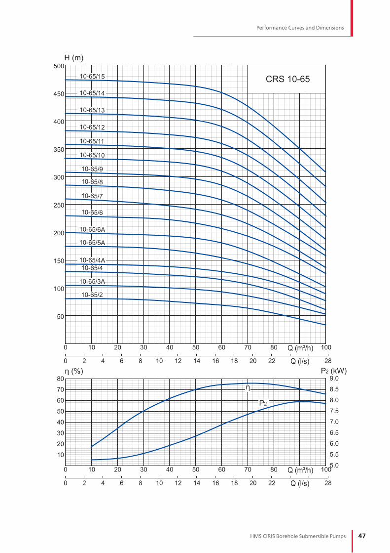
47HMS CIRIS Borehole Submersible Pumps
Performance Curves and Dimensions
80
70
60
50
40
30
20
10
100
500
10 20 30 40 50 60 70 80
450
400
350
300
250
200
150
100
50
η (%)9.0
8.5
8.0
5.0
5.5
6.0
6.5
7.0
7.5
η
0
0 2 4 6 8 10 12 14 16 18 20 22 28
10010 20 30 40 50 60 70 800
0 2 4 6 8 10 12 14 16 18 20 22 28
CRS 10-65
10-65/2
10-65/3A
10-65/410-65/4A
10-65/5A
10-65/6A
10-65/6
10-65/7
10-65/8
10-65/9
10-65/10
10-65/11
10-65/12
10-65/13
10-65/14
10-65/15
P2
Q (m³/h)
H (m)
P2 (kW)Q (l/s)
Q (m³/h)
Q (l/s)
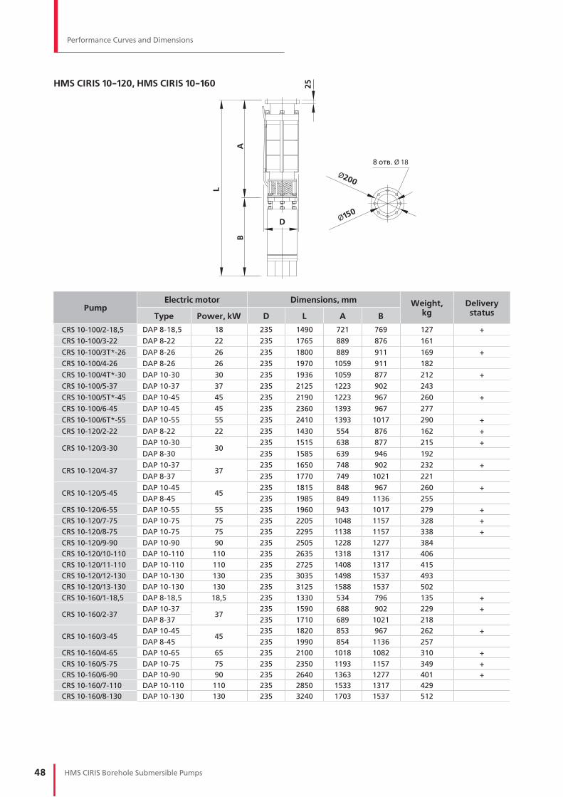
48 HMS CIRIS Borehole Submersible Pumps
Performance Curves and Dimensions
HMS CIRIS 10-120, HMS CIRIS 10-160
L
A
25
8 отв. Ø 18
Ø200
Ø150D
B
PumpElectric motor Dimensions, mm Weight,
kgDelivery
statusType Power, kW D L A B
CRS 10-100/2-18,5 DAP 8-18,5 18 235 1490 721 769 127 +
CRS 10-100/3-22 DAP 8-22 22 235 1765 889 876 161
CRS 10-100/3Т*-26 DAP 8-26 26 235 1800 889 911 169 +
CRS 10-100/4-26 DAP 8-26 26 235 1970 1059 911 182
CRS 10-100/4Т*-30 DAP 10-30 30 235 1936 1059 877 212 +
CRS 10-100/5-37 DAP 10-37 37 235 2125 1223 902 243
CRS 10-100/5Т*-45 DAP 10-45 45 235 2190 1223 967 260 +
CRS 10-100/6-45 DAP 10-45 45 235 2360 1393 967 277
CRS 10-100/6Т*-55 DAP 10-55 55 235 2410 1393 1017 290 +
CRS 10-120/2-22 DAP 8-22 22 235 1430 554 876 162 +
CRS 10-120/3-30DAP 10-30
30235 1515 638 877 215 +
DAP 8-30 235 1585 639 946 192
CRS 10-120/4-37DAP 10-37
37235 1650 748 902 232 +
DAP 8-37 235 1770 749 1021 221
CRS 10-120/5-45DAP 10-45
45235 1815 848 967 260 +
DAP 8-45 235 1985 849 1136 255
CRS 10-120/6-55 DAP 10-55 55 235 1960 943 1017 279 +
CRS 10-120/7-75 DAP 10-75 75 235 2205 1048 1157 328 +
CRS 10-120/8-75 DAP 10-75 75 235 2295 1138 1157 338 +
CRS 10-120/9-90 DAP 10-90 90 235 2505 1228 1277 384
CRS 10-120/10-110 DAP 10-110 110 235 2635 1318 1317 406
CRS 10-120/11-110 DAP 10-110 110 235 2725 1408 1317 415
CRS 10-120/12-130 DAP 10-130 130 235 3035 1498 1537 493
CRS 10-120/13-130 DAP 10-130 130 235 3125 1588 1537 502
CRS 10-160/1-18,5 DAP 8-18,5 18,5 235 1330 534 796 135 +
CRS 10-160/2-37DAP 10-37
37235 1590 688 902 229 +
DAP 8-37 235 1710 689 1021 218
CRS 10-160/3-45DAP 10-45
45235 1820 853 967 262 +
DAP 8-45 235 1990 854 1136 257
CRS 10-160/4-65 DAP 10-65 65 235 2100 1018 1082 310 +
CRS 10-160/5-75 DAP 10-75 75 235 2350 1193 1157 349 +
CRS 10-160/6-90 DAP 10-90 90 235 2640 1363 1277 401 +
CRS 10-160/7-110 DAP 10-110 110 235 2850 1533 1317 429
CRS 10-160/8-130 DAP 10-130 130 235 3240 1703 1537 512

49HMS CIRIS Borehole Submersible Pumps
Performance Curves and Dimensions
0 12010080604020
0 12010080604020 160
100
20
40
60
80
100
120
140
160
180
200
160
4.0
908070605040302010 4.5
5.0 5.56.06.57.07.58.08.59.0
η
5 10 15 20 25 30 35 450
5 10 15 20 25 30 35 450
P2
CRS 10-100
10-100/6
10-100/5
10-100/4
10-100/3
10-100/2
η (%)
Q (m³/h)
H (m)
P2 (kW)
Q (l/s)
Q (m³/h)
Q (l/s)

50 HMS CIRIS Borehole Submersible Pumps
Performance Curves and Dimensions
0 12010080604020 180140
η (%)
η 11.0
10.0
6.0
7.0
8.0
9.0
12.0
0 12010080604020 180140
80
70
60
50
40
30
20
10
40
80
120
160
200
240
280
320
360
400
0 5 10 15 20 25 30 35 40 50
0 5 10 15 20 25 30 35 40 50
10-120/1310-120/1210-120/1110-120/1010-120/9
10-120/8
10-120/7
10-120/6
10-120/5
10-120/4
10-120/3
10-120/2
CRS 10-120
P2
H (m)
Q (l/s)
Q (l/s)
P2 (kW)
Q (m³/h)
Q (m³/h)

51HMS CIRIS Borehole Submersible Pumps
Performance Curves and Dimensions
80
70
60
50
40
30
20
10
250
200
150
100
50
η (%)
13,0
11,5
10,0
14,5
16,0
17,5
19,0
20,5
22,0η
20020 40 60 80 100 120 140 1600
0 20105 15 403025 35 45 55
20020 40 60 80 100 120 140 1600
0 20105 15 403025 35 45 55
10-160/1
10-160/2
10-160/3
10-160/4
10-160/5
10-160/6
10-160/7
10-160/8
CRS 10-160
P2
H (m)
P2 (kW)Q (l/s)
Q (m³/h)
Q (l/s)
Q (m³/h)
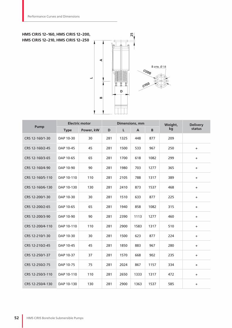
52 HMS CIRIS Borehole Submersible Pumps
Performance Curves and Dimensions
HMS CIRIS 12-160, HMS CIRIS 12-200,
HMS CIRIS 12-210, HMS CIRIS 12-250
PumpElectric motor Dimensions, mm Weight,
kgDelivery
statusType Power, kW D L A B
CRS 12-160/1-30 DAP 10-30 30 281 1325 448 877 209
CRS 12-160/2-45 DAP 10-45 45 281 1500 533 967 250 +
CRS 12-160/3-65 DAP 10-65 65 281 1700 618 1082 299 +
CRS 12-160/4-90 DAP 10-90 90 281 1980 703 1277 365 +
CRS 12-160/5-110 DAP 10-110 110 281 2105 788 1317 389 +
CRS 12-160/6-130 DAP 10-130 130 281 2410 873 1537 468 +
CRS 12-200/1-30 DAP 10-30 30 281 1510 633 877 225 +
CRS 12-200/2-65 DAP 10-65 65 281 1940 858 1082 315 +
CRS 12-200/3-90 DAP 10-90 90 281 2390 1113 1277 460 +
CRS 12-200/4-110 DAP 10-110 110 281 2900 1583 1317 510 +
CRS 12-210/1-30 DAP 10-30 30 281 1500 623 877 224 +
CRS 12-210/2-45 DAP 10-45 45 281 1850 883 967 280 +
CRS 12-250/1-37 DAP 10-37 37 281 1570 668 902 235 +
CRS 12-250/2-75 DAP 10-75 75 281 2024 867 1157 334 +
CRS 12-250/3-110 DAP 10-110 110 281 2650 1333 1317 472 +
CRS 12-250/4-130 DAP 10-130 130 281 2900 1363 1537 585 +
L
A
25
8 отв. Ø 18Ø200
Ø150
D
B
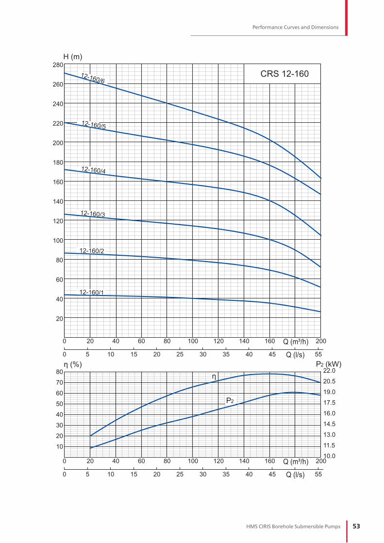
53HMS CIRIS Borehole Submersible Pumps
Performance Curves and Dimensions
80
70
60
50
40
30
20
10
280
260
240
220
200
180
160
140
120
100
80
60
40
20
η (%)
13.0
11.5
10.0
14.5
16.0
17.5
19.0
20.5
22.0η
20020 40 60 80 100 120 140 1600
0 20105 15 403025 35 45 55
20020 40 60 80 100 120 140 1600
0 20105 15 403025 35 45 55
CRS 12-160
12-160/1
12-160/2
12-160/3
12-160/4
12-160/5
12-160/6
P2
H (m)
P2 (kW)
Q (m³/h)
Q (l/s)
Q (m³/h)
Q (l/s)
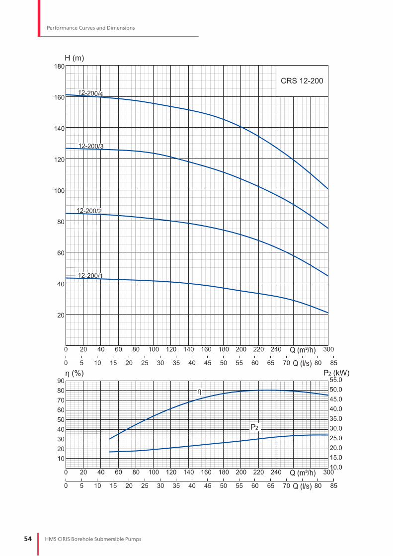
54 HMS CIRIS Borehole Submersible Pumps
Performance Curves and Dimensions
90
180
160
140
120
100
80
60
40
20
8070605040302010
η (%)
15.020.025.030.035.040.045.050.0
10.0
55.0
η
30020 40 60 80 100 120 140 160 180 200 220 2400
0 10 20 30 40 50 60 70 805 15 25 35 45 55 65 85
30020 40 60 80 100 120 140 160 180 200 220 2400
0 10 20 30 40 50 60 70 805 15 25 35 45 55 65 85
CRS 12-200
12-200/1
12-200/2
12-200/3
12-200/4
P2
H (m)
P2 (kW)
Q (m³/h)
Q (l/s)
Q (m³/h)
Q (l/s)

55HMS CIRIS Borehole Submersible Pumps
Performance Curves and Dimensions
908070605040302010
η (%)
15.020.025.030.035.040.045.050.0
10.0
55.0
η
20
40
60
80
10
30
50
70
30020 40 60 80 100 120 140 160 180 200 220 2400
0 10 20 30 40 50 60 70 805 15 25 35 45 55 65 85
30020 40 60 80 100 120 140 160 180 200 220 2400
0 10 20 30 40 50 60 70 805 15 25 35 45 55 65 85
CRS 12-21012-210/2
12-210/1
P2
H (m)
P2 (kW)
Q (m³/h)
Q (l/s)
Q (m³/h)
Q (l/s)

56 HMS CIRIS Borehole Submersible Pumps
Performance Curves and Dimensions
90
180
160
140
120
100
80
60
40
20
8070605040302010
η (%)
15.020.025.030.035.040.045.050.0
10.0
55.0
η
30020 40 60 80 100 120 140 160 180 200 220 2400
0 10 20 30 40 50 60 70 805 15 25 35 45 55 65 85
30020 40 60 80 100 120 140 160 180 200 220 2400
0 10 20 30 40 50 60 70 805 15 25 35 45 55 65 85
CRS 12-250
12-250/1
12-250/2
12-250/3
12-250/4
P2
H (m)
P2 (kW)
Q (m³/h)
Q (l/s)
Q (m³/h)
Q (l/s)

57HMS CIRIS Borehole Submersible Pumps
Accessories
ACCESSORIES
PIPE ADAPTERS
4 h
ole
s4
ho
les
8 h
ole
s
Ø1
76
Ø71
Ø1
8
Ø145
151
SP-114-D
SP-114-D
Ø1
83
Ø98
Ø1
8
Ø155
165
Ø2
15
Ø1
8
171
R3
”
Ø98
Ø180
18
25
25
АМТ6.411.021
DN 80. Models: CRS 8-16,
CRS 8-25, CRS 8-40
АМТ6.411.022
DN 100. Models: CRS 10-65
АМТ6.411.022-01
DN 100. Models: CRS 8-65
ADAPTER THREAD - FLANGE
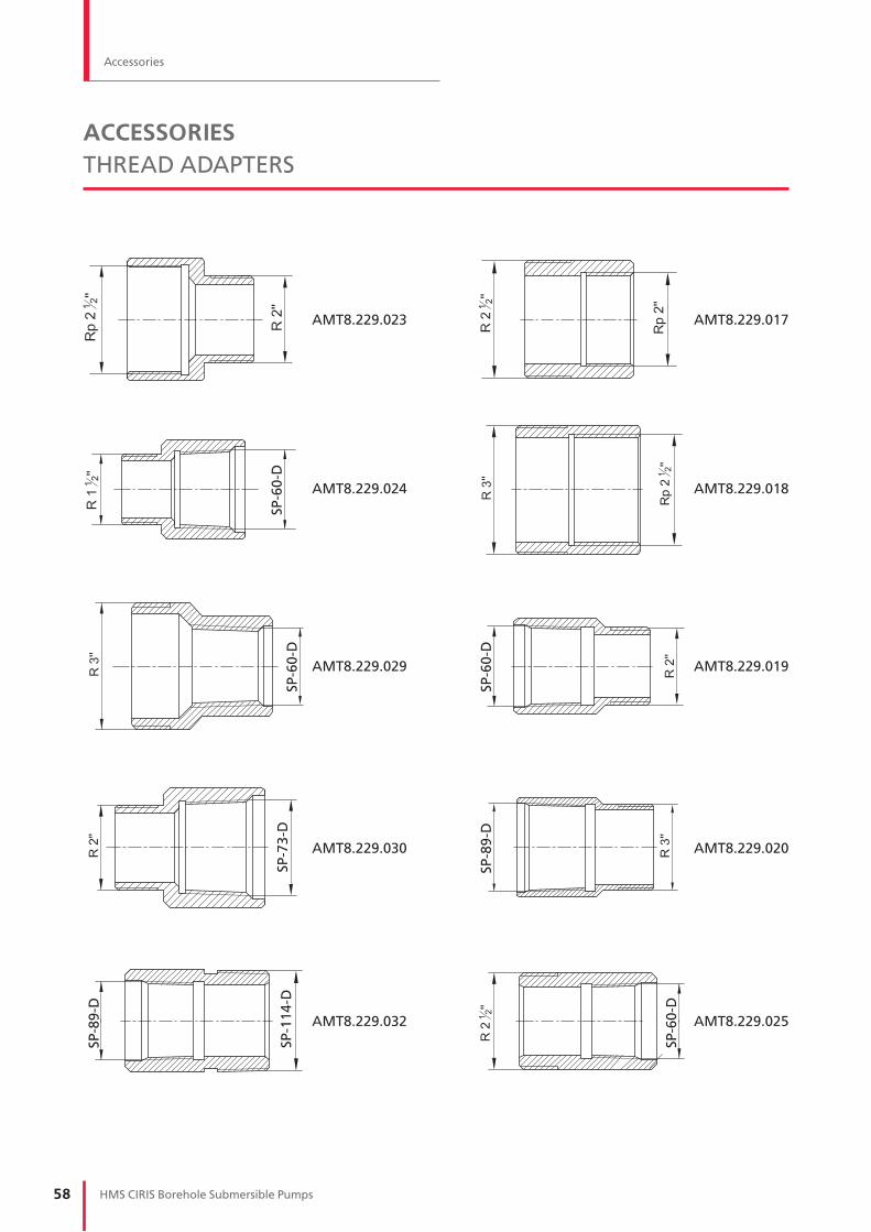
58 HMS CIRIS Borehole Submersible Pumps
ACCESSORIES
THREAD ADAPTERS
АМТ8.229.023
АМТ8.229.024
SP
-60
-DS
P-7
3-D
SP
-11
4-D
SP
-60
-D
SP
-60
-DS
P-8
9-D
SP
-89
-D
SP
-60
-DАМТ8.229.029
АМТ8.229.030
АМТ8.229.032
АМТ8.229.017
АМТ8.229.018
АМТ8.229.019
АМТ8.229.020
АМТ8.229.025
Accessories

59HMS CIRIS Borehole Submersible Pumps
Rewindable Submersible Motors. DAP Series
REWINDABLE SUBMERSIBLE MOTORS
DAP SERIES
FEATURES AND ADVANTAGES
— Motor is filled with a liquid allowing contact with potable water.
— Motor storage temperature: -30…+60 °С (-22…140 F)
— Lack of the liquid can be refilled with clean water (at storage temperature above +4 °С)
— Vertical and horizontal installation are equally possible (e.g. booster modules)
— Flanges and shafts are made in accordance with appropriate NEMA standards
— Resistance to unstable voltage
— Casing made of AISI 316 stainless steel
— Sand guard for mechanical seal protection from the solid particles
— Rotor’s «squirrel cage» is made of copper for increased efficiency
— High-temperature rewindable winding with PE2 insulation (up to 100 °С); temperature sensor is optionally available for overheating protection
— Radial bearings of composite materials with spiral grooves for better lubrication
— Heavy duty self-aligning water lubricated thrust bearing
— Counter thrust bearing for the rotor upward movement prevention
— Reliable mechanical seal the world’s leading manufacturers
— Rubber diaphragm for the liquid expansion compensation
1. NEMA shaft connection
2. Sand guard
3. Mechanical seal
4. Radial bearing
5. Squirrel cage made of copper
6. Rotor shaft made of AISI 409 stainless steel
7. High-temperature PE2 winding
8. Counter thrust bearing
9. Self-aligning thrust bearing
10. Cast Iron bottom part
11. Rubber diaphragm
1
2
3
4
5
6
7
8
9
10
11

60 HMS CIRIS Borehole Submersible Pumps
— Max Diameter: D=144 mm
— Protection: IP68
— Starts per hour: 6
— Water temperature: up to +30 °С (86 °F)
— Voltage: 50Hz, 3 х 400V
— Voltage tolerance: -15 … +10%
— PE2 winding insulation, up to 100 °С
temperature resistance
— Synchronous rotation speed: 3000 rpm
DAP 6 SERIES DAP 8 SERIES
— Max Diameter: D=189 mm
— Protection: IP68
— Starts per hour: 6
— Water temperature: up to +30 °С (86 °F)
— Voltage: 50Hz, 3 х 400V
— Voltage tolerance: -15 … +10%
— PE2 winding insulation, up to 100 °С
temperature resistance
— Synchronous rotation speed: 3000 rpm
DAP 6 DAP 8
Rewindable Submersible Motors. DAP Series
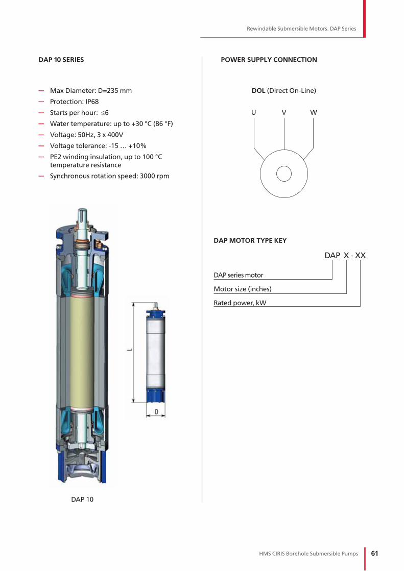
61HMS CIRIS Borehole Submersible Pumps
Rewindable Submersible Motors. DAP Series
— Max Diameter: D=235 mm
— Protection: IP68
— Starts per hour: 6
— Water temperature: up to +30 °С (86 °F)
— Voltage: 50Hz, 3 х 400V
— Voltage tolerance: -15 … +10%
— PE2 winding insulation, up to 100 °С
temperature resistance
— Synchronous rotation speed: 3000 rpm
POWER SUPPLY CONNECTION
DAP 10
U V W
DOL (Direct On-Line)
DAP 10 SERIES
DAP MOTOR TYPE KEY
DAP Х - ХХ
DAP series motor
Motor size (inches)
Rated power, kW

62 HMS CIRIS Borehole Submersible Pumps
ModelPower P2 F In Ist/ Inom Eff.
cosnn Tnom Tst/ Tnom Motor length Weight Leads
kW HP kN А А % rpm N·m N·m L, mm kg mm2
DAP 6-3 3 4 10 7 5.4 77 0.82 2900 10 1.5 597 38 4
DAP 6-4 4 5.5 10 9 5.4 78 0.82 2900 13 1.5 621 40 4
DAP 6-5.5 5.5 7.5 10 12 5.7 79 0.82 2900 18 1.6 641 42 4
DAP 6-7.5 7.5 10 10 17 5.6 80 0.82 2900 25 1.7 706 49 4
DAP 6-9 9 12 10 20 5.6 81 0.82 2900 30 1.6 731 51 4
DAP 6-11 11 15 10 24 6.3 81 0.82 2900 36 1.8 766 55 4
DAP 6-13 13 17.5 10 28 6 81 0.82 2900 43 1.7 821 60 4
DAP 6-15 15 20 10 32 5.9 82 0.82 2900 49 1.8 861 64 4
DAP 6-18.5 18.5 25 10 40 5.8 82 0.82 2900 61 1.8 906 69 4
DAP 8-11 11 15 15 22 4.7 83 0.86 2870 37 1.1 726 78 10
DAP 8-13 13 17.5 15 27 4.7 83 0.84 2870 43 1.1 756 81 10
DAP 8-15 15 20 15 31 4.7 83 0.84 2870 50 1.2 781 86 10
DAP 8-18.5 18.5 25 15 38 4.7 83 0.84 2870 62 1.2 769 89 10
DAP 8-22 22 30 15 44 5.1 85 0.85 2870 73 1.2 876 106 10
DAP 8-26 26 35 20 52 5.1 85 0.85 2870 87 1.2 911 114 10
DAP 8-30 30 40 20 60 5.1 85 0.85 2870 100 1.1 946 121 10
DAP 8-37 37 50 20 73 5.4 85 0.86 2870 123 1.4 1021 141 10
DAP 8-45 45 60 20 89 5.5 86 0.85 2870 150 1.5 1136 164 10
DAP 10-30 30 40 20 60 4.9 85 0.85 2900 99 1.1 877 144 25
DAP 10-37 37 50 20 72 5.4 86 0.86 2900 122 1.4 902 152 25
DAP 10-45 45 60 30 87 5.5 87 0.86 2900 148 1.5 967 169 25
DAP 10-55 55 74 30 106 5.4 87 0.86 2900 181 1.5 1017 182 25
DAP 10-65 65 87 30 125 5.3 87 0.86 2900 214 1.4 1082 202 25
DAP 10-75 75 100 30 145 4.9 88 0.85 2900 247 1.2 1157 225 25
DAP 10-90 90 121 45 174 5.2 88 0.85 2900 296 1.2 1277 262 35
DAP 10-110 110 161 45 212 5.2 88 0.85 2920 360 1.2 1317 274 50
DAP 10-130 130 174 45 251 5.8 88 0.85 2920 425 1.2 1537 342 50
TABLE № 6. OPERATING PARAMETERS
DAP submersible motors
Rewindable Submersible Motors. DAP Series

63HMS CIRIS Borehole Submersible Pumps
Pump Control Panels. HMS Control L3 Series
PUMP CONTROL PANELS
HMS Control L3 series
HMS Control L3 panels are intended to control
and protect the submersible pumps.
CONTROL MODES
— Manual
— Automatic
— Remote
APPLICATION
— Level control in tanks
— Pressure control
— Electric motor protection
FEATURES AND FUNCTIONS
— Dry running protection
— Water level control
— Mains voltage control
— Insulation resistance check before start
— Level sensor fault detection
— Pump shutdown in case of external accident
— Operation with float and electrode sensors
— Display of condition for station and sensors
— Display of pump parameters: input current,
voltage, running time and number of starts
— History of accidents
— Dispatching signals: «Accident», «Station is
on», «Pump is on», sensors
— Programmable on/off regime for pumps
— Group mode for several panels
OPTIONS
— Overvoltage protection
— Surge (lightning) protection
— Temperature sensor for motor winding
INTERFACE
— Sensor condition
— Current consumption
— Voltage on each phase
— Hours of operation
— Number of starts
— List of recent failures
TECHNICAL DATA
Voltage 3x400 V (+10%, -15%), 50 Hz
Current range 1..300A
Motor power up to 132 kW
Method of motor starting DOL or soft start
Ambient temperature -40 .. +40 °C
Humidity up to 100 %
Casing protection IP 24 or IP 54
Sensors and input signals
— Dry running — Pressure sensor
— Level sensor — Input «External control»
— Input «External error» — PT100/PTC temperature sensor

64 HMS CIRIS Borehole Submersible Pumps
HMS Control L3 - XXX - X - X.X - IPXX
DESIGNATION
PANEL SELECTION
Model
Maximum current, A
Start method: DOL / Soft start
Additional functions
H - High voltage protection
M - Lightning protection
C - Remote control by Modbus RTU
T - Temperature sensor
Protection: IP21; IP54
Examples
1. HMS Control L3-80-IP54
2. HMS Control L3-120-S-M.T-IP54
Available options:
N - overvoltage protection; panel is turned off to prevent the equipment failure
M - (lighting and switching) surge voltage protection
P - emergency main switch with handle on the door
C - Modbus interface support - remote monitoring and control: pump start/stop, operation/failure
T - motor winding temperature sensor
* Here and below approximate values are given. Some pump units may have different nominal current values at given
power. Please look for more details in References.
Control panels with DOL and Soft Start Rated current, А Motor power * , kW
HMS Control L3–25-IP21 HMS Control L3–25-IP54 1…25 1.1…9
HMS Control L3–40-IP21 HMS Control L3–40-IP54 20…40 11...17
HMS Control L3–60-IP21 HMS Control L3–60-IP54 35…60 18.5…22
HMS Control L3–80-IP21 HMS Control L3–80-IP54 55…80 27...37
HMS Control L3–100-IP21 HMS Control L3–100-IP54 75…100 45
HMS Control L3–120-IP21 HMS Control L3–120-IP54 95…120 50, 55
HMS Control L3–160-IP21 HMS Control L3–160-IP54 115…160 65, 75
HMS Control L3–200-IP21 HMS Control L3–200-IP54 155…200 90
HMS Control L3–250-IP21 HMS Control L3–250-IP54 195…250 110
HMS Control L3–300-IP21 HMS Control L3–300-IP54 245…300 132
Pump Control Panels. HMS Control L3 Series

65HMS CIRIS Borehole Submersible Pumps
Pump Control Panels. HMS Control L3 Series
RECOMMENDATIONS
How to select a control panel
Selection is made in accordance with the motor’s
rated current. Please look for motor data in the
relevant section, pump unit manual, name plate
or contact the manufacturer.
For instance, nominal current for HMS Ciris 10-110
pump is 12A, therefore HMS Control L3-25 shall
be selected for that pump.
In case you are unable to select pump or panel
range presented in the catalog does not provide
all requirements please fill out RFQ on page 67.
Control panels with soft start are recommended
for pumps with 7.5 kW power and higher.
Soft start provides:
— pump operational life increase
— no current and torque peaks and negligible
voltage dip during startup
— water hammer elimination in pipes and valves
How to select cable size to connect the pump
Cross-section is selected in accordance with
ampacity ratings, max ambient temperature and
max allowable voltage drop of 2% from nominal
value. Please use the table оn page 31.
Attention!
Different pump units with the same motor have different power consumption, therefore the cable length and cross-section are to be selected in accordance with nominal current value to avoid oversizing.
If operating current is 10% lower than nominal, the cable length shall be 10% longer than given in the table.
Example
Cable sizing for HMS CIRIS 8-25-125 pump with 13 kW power and 33 A nominal current and 160 m of required length.
In the table below, vertical column, in the corres- ponding row you would find 175 of cable length with 25 mm of cross section. Therefore, at the required cable length of 160 m the cable cross-section will be 25 mm.
Correct connection to power supply is determined by the pump rotation direction. At the closed valve the manometer shows two different pressure values. Higher value points to the correct rotation direction. For submersible pumps water lift, in the normal mode, should be indicated in 1-2 minutes after start.
Connection of any two-phase power wires has to be swapped around in case of wrong rotation direction.
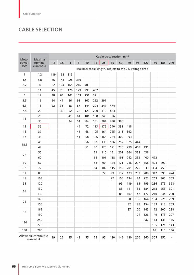
66 HMS CIRIS Borehole Submersible Pumps
Cable Selection
CABLE SELECTION
Motor power,
kW
Maximal nominal
current, A
Cable cross-section, mm2
1.5 2.5 4 6 10 16 25 35 50 70 95 120 150 185 240
Maximal cable length, subject to the 2% voltage drop
1 4.2 119 198 315
1.5 5.8 86 143 228 339
2.2 8 62 104 165 246 403
3 11 45 75 120 179 293 457
4 12 38 64 102 153 251 391
5.5 16 24 41 66 98 162 252 391
6.3 18 22 36 58 87 144 224 347 474
7.5 20 32 52 78 128 200 310 423
1125 41 61 101 158 245 336
30 34 51 84 131 204 280 386
13 35 44 72 113 175 240 331 418
15 37 41 68 105 164 225 311 392
17 38 41 68 106 164 224 309 393
18.545 56 87 136 186 257 325 444
49 51 80 125 171 236 299 408 491
2255 71 110 151 209 264 362 436
60 65 101 138 191 242 332 400 473
30 67 58 90 124 171 216 297 358 424 492
32 72 54 84 115 159 201 276 333 394 458
37 83 72 99 137 173 239 288 342 398 474
45 108 77 106 134 184 222 263 305 363
55 120 95 119 165 199 236 275 328
65130 88 111 153 184 218 253 301
135 85 107 147 177 210 244 290
75146 98 136 164 194 226 269
155 92 128 154 183 213 253
90165 87 120 145 172 200 238
190 104 126 149 173 207
110250 96 113 131 155
270 105 121 143
130 285 99 115 136
Allowable continuous current, A
19 25 35 42 55 75 95 120 145 180 220 260 305 350 -

The HMS Group
HMS GROUP is the leading in Russia and CIS
manufacturer of the pumping and compressor
equipment and integrated solutions provider for
oil & gas, nuclear & thermal energy, water & utilities.
Кey Facts and Figures
HMS Group foundation – 1993
Manufacturing facilities in Rus sia, Ukraine,
Belarus and Germany
Over 17 000 employees
Representative offices in Italy, UAE, Iraq,
Turkmenistan and Uzbekistan
Main Business Activities
Pumps
Oil & gas industry applications
(including API 610 11th ed. pumps)
Termal & nuclear energy applications
Water supply & sewage disposal
Steel, mining and other industries
Compressors
Centrifugal compressors
Screw compressors
Turbo-compressor packages
Refrigerating machines
Oil & Gas equipment
Modular and skid-mounted units
Mobile & stationary cement storages
Downhole equipment
Tanks, pressure vessels, heat exchangers
Flow meters
Integrated Client Support
Project Audit
Technical audit
Scope of works definition
Project scheduling and budgeting
Engineering, Procurement,
Manufacture, Testing
Design and engineering dossier
Manufacturing of main process equipment
(pumps, compressors, pressure vessels,
heat exchangers)
Outsourcing of auxiliaries
Factory assembly
Factory Acceptance Test
Supply and Site Services
Shipment
Site installation
Pre-commissioning
Site Performance Tests
Site Supervision and on-the-job training
After sales servicing and counseling
Quality
HMS Group Quality Management System
complies with ISO 9001:2008. The equipment is
manufactured in accordance with internationally
recognized ISO, ANSI, DIN, ASME, ATEX and API
standards and in accordance with the customer
specifications as well.
Global Presence
The HMS Group references list includes
the international projects in Russia and the CIS,
Western and Eastern Europe, Iraq, Indonesia,
India, China, the USA and other countries.

Temperature: oC Turbidity: mg/L Total dissolved solids: mg/L pH:
Water supplies to (select one of two values): Tank Water supply system
Alkalinity: mg/L Hardness (total): mg/L Iron (total): mg/L
Pump switch-on pressure: kgf/cm2 Pump switch-off pressure: kgf/cm2
Capacity: m3 Well head pressure: kgf/cm2
5. Power and control panel
4. Operation
REQUEST FOR QUOTATION
(ORDER FORM)
The order form shall be completed in full to be accepted for consideration by the HMS Group
1. Сustomer:
Address:
Phone: Fax: E-mail:
Pump type: Quantity: Estimated annual q-ty required:
Filled in by (Name): Position: Date:
Well #: Well diameter: m Well depth: m Pump installation dept: m
Static level: m Dynamic level: m Lowering: m Output: m3/h
Relative output: m3/h
3. Pumped liquid parameters
2. Pump installation data
Installed in a new well Installed into a well in operation
Control panel required Control type: By pressure By water level
Motor protection options: By min/max voltage By number of starts limit By current
Other requirements (point if any):
Phase rotation Phase failure Phase imbalance
Soft start required Variable frequency drive required
Level sensor
Similar to model: by (manufacturer):


HM
S 1
17
E 2
40
12
01
4 E
NG
12, Aviakonstruktora Mikoyana str.,
Moscow, 125252, Russia
e-mail: [email protected]
www. grouphms.com
www. hms.biz
Phone: + 7 (495) 664 8171
Fax: + 7 (495) 664 8172
HYDROMASHSERVICE is an integrated commercial and engineering company of the HMS Group.
We are looking for experienced dealers & distributors to sell products and services.
Please forward your queries to below contact details:
Information contained in this catalogue is for reference purposes and to select products developed and manufactured by HMS Group. You can find full technical information on all our products in the relevant technical manuals.
HMS Group reserves the right to alter their products without notice and is not responsible for possible errors in catalogs, brochures and other printed materials.


![NORTA MIT PRESENTATION.pptx [Read-Only] · • Centrifugal pumps • Side channel pumps • Gear pumps • Screw pumps • Single screw pumps • Piston pumps • Vacuum pumps •](https://img.dokumen.tips/doc/110x75/5ec27ab9e3ef591d10504c3a/norta-mit-read-only-a-centrifugal-pumps-a-side-channel-pumps-a-gear-pumps.jpg)