Embed Size (px)
Citation preview
1 | Circular fire damper user manual 11/2019
Gradna 78A, 10430 SamoborCroatia | Hrvatska+385 (0)1 33 62 513
www.klimaoprema.hr
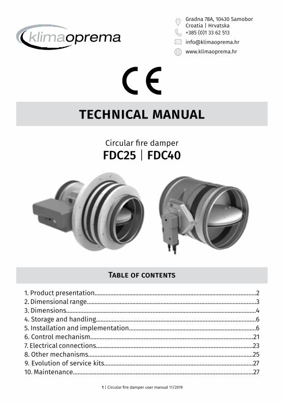
technical manual
Circular fire damperFDC25 | FDC40
Table of contents
1. Product presentation.......................................................................................................22. Dimensional range............................................................................................................33. Dimensions.........................................................................................................................44. Storage and handling......................................................................................................65. Installation and implementation.................................................................................66. Control mechanism........................................................................................................217. Electrical connections....................................................................................................238. Other mechanisms.........................................................................................................259. Evolution of service kits...............................................................................................2710. Maintenance...................................................................................................................27

2 | Circular fire damper user manual 11/2019
1. Product presentation
Fire dampers FDC25/FDC40 are installed in ventilation ducts between fire compartments in order to stop the spread of fire and smoke trough the duct. They have a modular (manual or magnet) or motorized mechanism, entirely outside the wall. Casing is made out of galvanized steel sheet, damper blade is made of special insulating material, and damper blade shaft and push rod are made of stainless steel. Bearings are made of brass, seals of polyurethane and elastomer. The fire damper can be equipped with a simple mechanism with thermal fuse, or with solenoid actuator mechanism or with electric actuator mechanism..
• Tested according to EN 1366-2 up to 500 Pa• Airtightness according to standard EN 1751 class C• Approved for installation in a concrete wall, a concrete slab, plasterboard wall and gypsum
blocks wall• Operating mechanism completely outside the wall• Easy to install• Maintenance free
1. Galvanized steel casing2. Fire resistant damper blade3. Control mechanism4. Intumescent joint5. Connection flanges6. Product marking on the casing7. Thermal fuse
1. Gypsum layers2. Intumescent joint3. Cold smoke seal4. Boundary layer
1
3
45
2
6
7
1
23
4

3 | Circular fire damper user manual 11/2019
2. Dimensional range
Free area for dimensions Ø100 do Ø315 (blade 25mm) (dm²) = [(π x (Ø-3)2/4)-25 x (Ø-5)]/10 000 Free area for dimensions Ø350 do Ø800 (blade 40mm) (dm²) = [(π x (Ø-3)2/4)-40 x (Ø-5)]/10 000
Diameter (mm) Gross section (dm²) Netto area (dm²)
FDC25
100 0,74 0,50125 1,17 0,87160 1,93 1,55200 3,05 2,56250 4,79 4,18300 6,18 5,74315 7,64 6,87
FDC40
355 9,73 8,33400 12,37 10,79450 15,69 13,91500 19,39 17,41630 30,86 28,36710 39,24 36,42800 49,86 46,68
Diameter (mm) Gross section (dm²) Netto area (dm²)
FDCApplique
100 3,30 0,50125 3,80 0,87160 5,11 1,55200 6,16 2,56250 8,55 4,18315 12,25 6,87

4 | Circular fire damper user manual 11/2019
3. Dimensions
380 ∅n/2+12 ∅n/2+22220
Y
E
D
AC
D∅n
380 0 n/2+12 0 n/2+220
n
Y
101
A
E
Y
D
AC
∅n
380 ∅n/2+12
C
∅n/2+22
FDC25-R
FDC40-R
FDC25/40 M
Product A C D E
BelimoBFL (M) 25 200 90 120BFN (M) 25 225 100 120BF (M) 50 250 100 120
Klimaoprema-R (FD 25 & FDC 25) 55 150 105 150-R (FD 40 & FDC 40) 55 200 105 200
-EMS/EMP (FD 25/40 & FDC 25/40) 55 200 105 200

5 | Circular fire damper user manual 11/2019
∅n
380100 45
∅n+
A
(∅n/2)+80 (∅n/2)+94
(∅n/2)+80 (∅n/2)+124
380100 45
∅n
∅n+
A
45
∅n+
A
380
145
∅n+16045
∅n+
A
380
145
∅n+160
(∅n/2)+80 (∅n/2)+124
380100 45
∅n
∅n+
A
∅n
380100 45
∅n+
A
(∅n/2)+80 (∅n/2)+94FDC APPLIQUE
Damper diameter Øn[mm] Applique frame diameter [mm]
100 Øn+105mm125-180 Øn+95mm200-315 Øn+80mm
6 | Circular fire damper user manual 11/2019
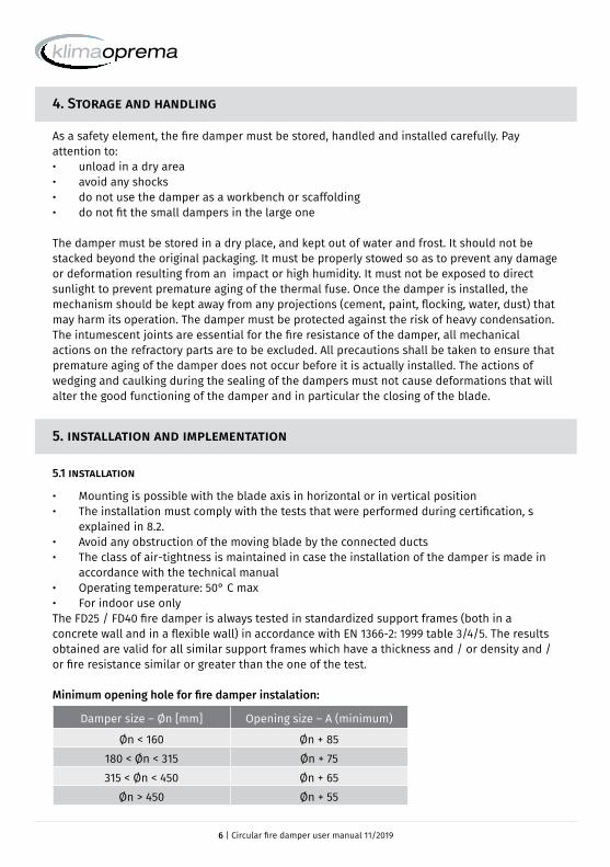
4. Storage and handling
As a safety element, the fire damper must be stored, handled and installed carefully. Pay attention to:• unload in a dry area• avoid any shocks• do not use the damper as a workbench or scaffolding• do not fit the small dampers in the large one
The damper must be stored in a dry place, and kept out of water and frost. It should not be stacked beyond the original packaging. It must be properly stowed so as to prevent any damage or deformation resulting from an impact or high humidity. It must not be exposed to direct sunlight to prevent premature aging of the thermal fuse. Once the damper is installed, the mechanism should be kept away from any projections (cement, paint, flocking, water, dust) that may harm its operation. The damper must be protected against the risk of heavy condensation. The intumescent joints are essential for the fire resistance of the damper, all mechanical actions on the refractory parts are to be excluded. All precautions shall be taken to ensure that premature aging of the damper does not occur before it is actually installed. The actions of wedging and caulking during the sealing of the dampers must not cause deformations that will alter the good functioning of the damper and in particular the closing of the blade.
5. installation and implementation
5.1 installation
• Mounting is possible with the blade axis in horizontal or in vertical position• The installation must comply with the tests that were performed during certification, s
explained in 8.2.• Avoid any obstruction of the moving blade by the connected ducts• The class of air-tightness is maintained in case the installation of the damper is made in
accordance with the technical manual• Operating temperature: 50° C max• For indoor use onlyThe FD25 / FD40 fire damper is always tested in standardized support frames (both in a concrete wall and in a flexible wall) in accordance with EN 1366-2: 1999 table 3/4/5. The results obtained are valid for all similar support frames which have a thickness and / or density and / or fire resistance similar or greater than the one of the test.
Minimum opening hole for fire damper instalation:
Damper size – Øn [mm] Opening size – A (minimum)
Øn < 160 Øn + 85180 < Øn < 315 Øn + 75315 < Øn < 450 Øn + 65
Øn > 450 Øn + 55

7 | Circular fire damper user manual 11/2019
5.2 Installation and sealing
5.2.1 Concrete wall and reinforced concrete wall installationThe wall is composed of concrete blocks (minimum density of 550 kg/m³) and with a minimum thickness of 100 mm.
5.2.2 Aerated concrete ceiling installation and reinforced concrete ceiling installationThe ceiling is made of aerated concrete with a minimum density of 550 kg/m³ and a minimum thickness of 100 mm
Place the damper in an openingaccording to table (on pg. 6)
Fix the damper to the wall using screws (screw hole is 6mm in
diameter)
Fill the space between the damper and the wall with mortar
Place the damper in an opening according to table
(on pg. 6)
Fix the damper to the slab using screws (screw hole is 6mm in
diameter)Fill the space between the damper
and the slab with mortar

8 | Circular fire damper user manual 11/2019
5.2.3 Gypsum blocks wall 70mmThe wall is composed of gypsum blocks (minimum density of 995kg/m³), and with minimum thickness of 70mm.
Place the damper in an openingaccording to table (on pg. 6)
Fix damper and GKF gypsum boards (12,5mm thick) to wall with screws (screw hole is 6mm in diameter)
Fill the space between the damper and the wall with mortar
Cover the mortar with GKF gypsum boards (12,5 mm thick)
* The Kit is universal for all dimensions and must be cut to fit the specific
dimensions of the damper
Diameter of the damper (mm) Mounting kit
100 60061429125 60061430160 60061431200 60061432250 60061433315 60061435355 60061436400 60061437450 60061438500 60061439560 60061440630 60061441710 60061442800 60061443

9 | Circular fire damper user manual 11/2019
5.2.4 Gypsum blocks wall 100mmThe wall is composed of gypsum blocks (minimum density of 995kg/m³), and with minimum thickness of 100mm.
Fix the damper to the wall using screws (screw hole is 6mm in
diameter)
Fill the space between the damper and the wall with mortar
Cover the mortar with GKF gypsum boards (12,5 mm thick)
Place the damper in an openingaccording to table (on pg. 6)
* The Kit is universal for all dimensions and must be cut to fit the specific
dimensions of the damper
Diameter of the damper (mm) Mounting kit
100 60061429125 60061430160 60061431200 60061432250 60061433315 60061435355 60061436400 60061437450 60061438500 60061439560 60061440630 60061441710 60061442800 60061443

10 | Circular fire damper user manual 11/2019
5.2.5 Flexible wall mounting (mineral wool sealing)The wall is composed of 2x2 GKF plates, 12.5 mm thick, installed on a 48 mm wide steel construction. The interior of the wall is filled with mineral wool of 100 kg/m³ density.
625 625 > 440
Realization of the steel construction
Place the damper in an openingaccording to table (on pg. 6)
Fix the damper to the wall using screws (screw hole is 6mm in
diameter)
Fill the space between the damper and the wall with mineral wool (100
kg/m³ of density)
Cover the mineral wool with GKF gypsum boards (12,5 mm thick)
* The Kit is universal for all dimensions and must be cut to fit the specific
dimensions of the damper
Diameter of the damper (mm) Mounting kit
100 60061429125 60061430160 60061431200 60061432250 60061433315 60061435355 60061436400 60061437450 60061438500 60061439560 60061440630 60061441710 60061442800 60061443
11 | Circular fire damper user manual 11/2019
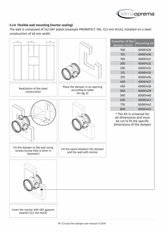
5.2.6 Flexible wall mounting (mortar sealing)The wall is composed of 2x2 GKF plates (example PROMATECT 100, 12,5 mm thick), installed on a steel construction of 48 mm width.
625 625 > 440
Realization of the steel construction
Place the damper in an opening according to table
(on pg. 6)
Fix the damper to the wall using screws (screw hole is 6mm in
diameter)
Fill the space between the damper and the wall with mortar
Cover the mortar with GKF gypsum boards (12,5 mm thick)
* The Kit is universal for all dimensions and must be cut to fit the specific
dimensions of the damper
Diameter of the damper (mm) Mounting kit
100 60061429125 60061430160 60061431200 60061432250 60061433315 60061435355 60061436400 60061437450 60061438500 60061439560 60061440630 60061441710 60061442800 60061443

12 | Circular fire damper user manual 11/2019
5.2.9 Installation in flexible wall (Weichschott)Installation material: Fire damper FDC, Mineral wool >140kg/m³, Fire protection coating, (HILTI weichschott system).
Recommended wall opening forfire damper installation is Ø +400mm, but openings from Ø +80…600 mm can also be used
Insert fire damper into wallDamper blade must be closed
during installation!
Space between casing and wallclose with two layers of mineral
wool (density 140 kg/m³ or more, coated on one side)
Connections of mineral wool seal with intumescent fire resistant
sealant (e.g. Promastop-I or Hilti CFS-CT). Mineral wool and damper casing must be coated with 2 mm thick fire
protection coating

13 | Circular fire damper user manual 11/2019
5.2.7 Installation remote from flexible/rigid wallThe wall is composed of 2x2 GFK plates, 12.5 mm thick, installed on a 48 mm wide steel construction. The interior of the wall is filled with mineral wool of 100 kg/m³ density.
700
Øn+80
Øn+
80
Arrangement of steel profilesPlace the damper in an opening
according to table (on pg. 6) (wall cover with gypsium plates)
Place ventilation duct trough wall (thickness of threaded rod for
suspension should be M12 or more)
Install fire damper and secure it with self-tapping screws 4,3x10 to duct
(every 300mm)
Fill space between duct and wall with mineral wool (Isover U protect, min.
80mm thickness). Additionally paint wool with Isover BSF in thickness of 1mm
Repeat the same procedure on the other side. Place the wool on
ventilation duct in lenght of 80mm
Close installation with L profiles 30x30x3mm. Additionally fix profiles to
duct with self-tapping screws, and screw them to wall with 4,5x50 screws with
200mm distance between them
Place steel protection on place where insulation on damper ends (80x80mm,
1mm thick metal sheet cover)
On connection wool-wall applyglue Isover BSK in thickness of 2mm

14 | Circular fire damper user manual 11/2019
5.2.8 Installation in ceiling (Weichschott)The ceiling is composed of concrete blocks (minimum density of 550 kg/m³) and with a minimum thickness of 100 mm.
Recommended ceiling openingfor fire damper installation isØ+ 400mm, but openings from
Ø + 80…600 mm can also be used
Insert fire damper into ceilingDamper blade must be closed
during installation!
Space between casing and wallclose with two layers of mineral
wool (density 140 kg/m³ or more, 50 mm thick, coated on one side)
Connections of mineral wool should be sealed with intumescent fire resistant sealant
(e.g. Promastop-I or Hilti CFS-CT). Mineral wool and damper casing must be coated with
2 mm thick fire protection coating
5.2.10 Suspension for mortarless installationSuspension systems are required for the dry mortarless installation of the fire damper with mineral wool in solid walls, flexible walls and ceiling slabs. Fire dampers can be suspended from solid ceiling slabs using adequately sized threaded rods. Load the suspension system only with the weight of the fire damper. Ducts must be suspended separately.
1
32
1
4 5
Dn + 70Dn + 70
Wall installation Ceiling installation Threaded rod (M10), galvanized steel
Washer, galvanized steel
Nut, galvanized steel
Bracket, 45x30x1,5 mm, galvanized steel
L shaped profile (50x50x1) secured with self tapping screw to damper housing
1
2
3
4
5

15 | Circular fire damper user manual 11/2019
5.2.11 Installation in gypsum blocks wall 70mmThe wall is composed of gypsum blocks (minimum density of 995kg/m³), and with minimum thickness of 70mm.
30
30
30
45º
30
150
150
Prepare opening in the wall according to dimension table (on
page 6)Insert fire damper into wall
Fire damper can be installed with minimal distance of 30 mm between
wall, ceiling or other dampers.
Cover the mortar with GKF gypsum boards (12,5 mm thick)
Space between casing and wallclose with mortar

16 | Circular fire damper user manual 11/2019
5.2.12 Installation in gypsum blocks wall 100mmThe wall is composed of gypsum blocks (minimum density of 995kg/m³), and with minimum thickness of 100mm.
30
30
30
45º
30
150
150
Prepare opening in the wall according to dimension table
(on page 6)Insert fire damper into wall
Fire damper can be installed with minimal distance of 30 mm between
wall, ceiling or other dampers.
Mineral wool and damper casing must be coated with 2 mm thick
fire protection coating
Space between casing and wallclose with mortar
17 | Circular fire damper user manual 11/2019
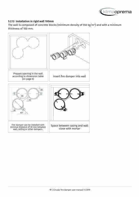
5.2.13 Installation in rigid wall 100mmThe wall is composed of concrete blocks (minimum density of 550 kg/m³) and with a minimum thickness of 100 mm.
30
30
30
45º
30
Prepare opening in the wall according to dimension table
(on page 6)Insert fire damper into wall
Fire damper can be installed with minimal distance of 30 mm between
wall, ceiling or other dampers.Space between casing and wall
close with mortar

18 | Circular fire damper user manual 11/2019
5.2.14 Flexible wall mountingThe wall is composed of 2x2 GKF plates, 12.5 mm thick, installed on a 48 mm wide steel construction. The interior of the wall is filled with mineral wool of 100 kg/m³ density.
30
30
30
45º
30
Arrangement of steel profiles according to drawing. Prepare
opening in the wall according to dimension table (on page 6)
Insert fire damper into wall
Mineral wool and damper casing must be coated with 2 mm thick
fire protection coating
Space between casing and wallclose with two layers of mineral
wool (density 140 kg/m³
Fire damper can be installed with minimal distance of 30 mm between
wall, ceiling or other dampers.

19 | Circular fire damper user manual 11/2019
5.2.13 Installation in rigid floor 100mmThe floor is composed of concrete blocks (minimum density of 550 kg/m³) and with a minimum thickness of 100 mm.
30
30
30
45º
30
Prepare opening in the wall according to dimension table
(on page 6)Insert fire damper into floor
Fire damper can be installed with minimal distance of 30 mm between
wall, ceiling or other dampers.Space between casing and wall
close with mortar
20 | Circular fire damper user manual 11/2019
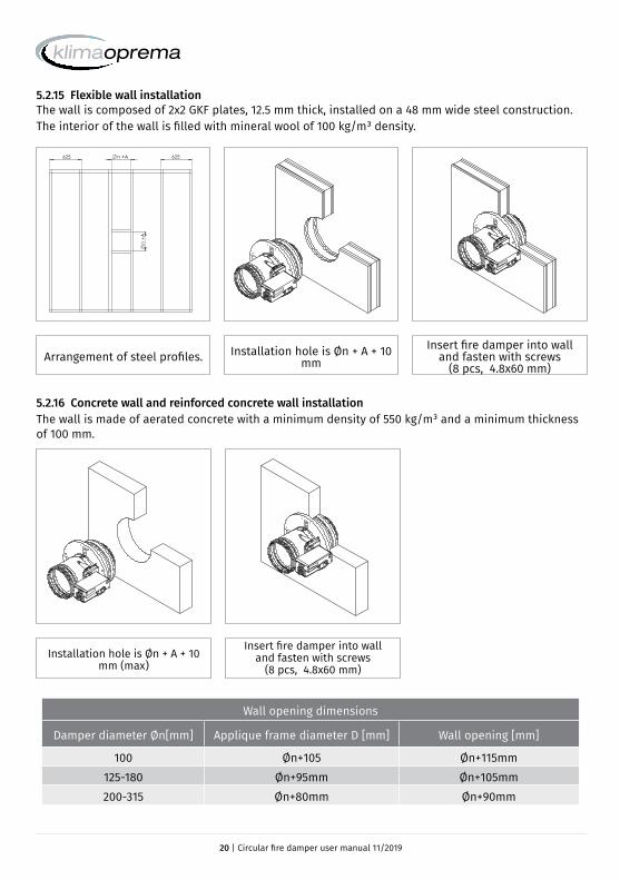
5.2.15 Flexible wall installationThe wall is composed of 2x2 GKF plates, 12.5 mm thick, installed on a 48 mm wide steel construction. The interior of the wall is filled with mineral wool of 100 kg/m³ density.
5.2.16 Concrete wall and reinforced concrete wall installationThe wall is made of aerated concrete with a minimum density of 550 kg/m³ and a minimum thickness of 100 mm.
Arrangement of steel profiles. Installation hole is Øn + A + 10 mm
Insert fire damper into walland fasten with screws
(8 pcs, 4.8x60 mm)
625 625
n
+A
n +A
Installation hole is Øn + A + 10 mm (max)
Insert fire damper into walland fasten with screws
(8 pcs, 4.8x60 mm)
Wall opening dimensions
Damper diameter Øn[mm] Applique frame diameter D [mm] Wall opening [mm]
100 Øn+105 Øn+115mm125-180 Øn+95mm Øn+105mm200-315 Øn+80mm Øn+90mm

21 | Circular fire damper user manual 11/2019
6. Control mechanism
MANUAL FUSE ONLY MECHANISMSelf-operating mechanism equipped with a thermal fuse.The Manual fuse only control mechanism closes the damper blade automatically if the temperature in the duct exceeds72 °C. The damper is reset manually by means of a screwdriver.Standard equipment:• Thermal fuse 72 °C• Manual triggering is possible• Manual reset, use the screwdriver (turn counterclockwise)
To open the damper, insert the screwdriver into the shaft (parallel to the ventilation duct axis)
and turn counterclockwiseTo close the damper, press the thermal fuse
head with a screwdriver
OPTIONSFor this self-operating version, the double contact – S - is available as an option (factory option or after-sales kit):The double contact S (OPEN / CLOSED) consists of:• electric limit switch indicating CLOSED position• electric limit switch indicating OPEN position
MANUAL FUSE ONLY MECHANISM UPGRADABLE TO SOLENOID ACTUATORFD25/FD40 in self-operating versionActivation :• Manual activation: Push the release button.• Self-operating activation: With a fuse at 72 ºCResetting :• Manual reset: Turn the screwdriver counter clockwise

22 | Circular fire damper user manual 11/2019
To open the damper, insert the screwdriver into the shaft (parallel to the ventilation duct axis)
and turn counterclockwiseTo close the damper, press the thermal fuse
head with a screwdriver
OPTIONS• For this self-operating version, the double contact – S and the 4-contacts – S2 - are
available as an option (factory option or after-sales kit):The 4-contact – S2 - consists of:• electric limit switch indicating CLOSED position• electric limit switch indicating OPEN position• additional electric limit switch indicating CLOSED position• additional electric limit switch indicating OPEN
FD25/FD40 solenoid actuator version: EVO T
Activation:• Manual activation: Push the release button.• Self-operating activation: With a fuse at 72 ºC• Remote activation: By emission or break of current (solenoid with 24/48 V automatic
voltage)
Resetting:• Réarmement manuel : Tourner le levier dans le sens anti horaire
Reminder:• For this version with remote activation, the double contact S (OPEN / CLOSED) are mounted
as standard equipment• The 4-contact – S2 - are available as an option (factory option or after-sales kit).

23 | Circular fire damper user manual 11/2019
7.Electrical connections
FD25 MANUAL FUSE ONLY MECHANISM
• Electrical wiring of the S option Electronic control board
MANUAL FUSE ONLY MECHANISM UPGRADABLE TO SOLENOID ACTUATOR
• Electrical wiring of solenoid option Main electronic control board of coil supply
MOT = not in use MAG = solenoid power supply terminals (24 or 48 VDC)
• Electrical wiring of the S option Main electronic control board of coil supply
FC = Limit switch - end C = common NF = normally closedDC = Limit switch - start NO = normally open
FC = Limit switch - end C = common NF = normally closedDC = Limit switch - start NO = normally open

24 | Circular fire damper user manual 11/2019
• Electrical wiring of the S2 option (4 contactors). Electronic control board
Electrical specifications FD fuse only FD fuse only upgradable t
Nominal voltage N/A Solenoid: 24/48 VDC (automatic change on the electronic card)
Power N/ADual voltage SOLENOID:
• Break of current: Pnom = 1.6W• Emission of current: Pmax = 3.5 W
Switching capacity 1mA…500mA, 5VDC…48VDC 1mA…500mA, 5VDC…48VDC
Blade closure timeBlade opening time
Spring: 1 secondManual Spring: 1 second
Degree of protection IP 42 IP 42
FC = Limit switch - end C = common NF = normally closedDC = Limit switch - start NO = normally open

25 | Circular fire damper user manual 11/2019
8. Other mechanism
BELIMO
OperationDamper is delivered in closed position. When electric actuator is connected to the power supply damper will open. When the damper reaches the end position (damper open), in which is it blocked, the electromotor will stop. Closing fire damper takes place automatically when a power failure occurs. Thermal tripping device that comes with fire damper causes power circuit break at a temperature of 72 °C (inside or outside duct). If checking is needed for proper functioning of fire damper, pushing the switch on the thermal tripping device will close damper. When switch on tripping device is released, the damper will open.Damper can be opened without connecting to a voltage with enclosed handle turning in the direction of the arrow on electric actuator (clockwise). Damper can be locked in the desired position by fast turning back handle a quarter of a turn (counterclockwise) for Belimo BF, and by puling brake on Belimo BFL and BFN. To unlock the electromotor, turn handle clockwise for a quarter of a turn for Belimo BF, or release brake for Belimo BFL and BFN. After release, damper will be closed by return spring. When damper is opened manually, electric actuator will not move the damper into closed position after power failure.
Wiring diagram
1 negative (direct-current) or neutral (alternating current)2 positive (direct-current) or faze (alternating current)S1 common micro switch closed damperS2 normally closed micro switch closed damperS3 normally open micro switch closed damperS4 common micro switch open damperS5 normally closed micro switch open damperS6 normally open micro switch open damperTf1 temperature sensor on the outer side of the duct (ambienttemperature) max. 72°CTf2 temperature sensor on the inner side of the duct (temperature in the duct) max. 72°CTf3 temperature sensor on the inner side of the duct (temperature in the duct) max. 72°C

26 | Circular fire damper user manual 11/2019
Type of Belimo actuator BFL24-T BFN24-T BFL230-T BFN230-T BF24-T BF230-T
Nominal voltage /
power con-sumption
voltage AC/DC 24V, 50/60Hz
AC 24V, 50/60Hz
AC 230V, 50/60Hz
AC 230V, 50/60Hz
AC/DC 24V, 50/60Hz
AC 230V, 50/60Hz
opening 2,5 W 4 W 3,5 W 5 W 7 W 8.5 W
holding 0,8 W 1,4 W 1,1 W 2,1 W 2 W 3 W
for wire sizing 4 VA 6 VA 6,5 VA 10 VA 10 VA 11 VA
End switch
1 mA...3 A (0,5 A),
DC 5 V...AC 250V
1 mA...3 A (0.5 A),
DC 5 V...AC 250 V
1 mA...3 A (0.5 A),
DC 5 V...AC 250 V
1 mA...3 A (0.5 A),
DC 5 V...AC 250 V
1 mA...6 A (3 A), DC 5 V...AC 250 V
1 mA...3 A (0.5 A),
DC 5 V...AC 250 V
Running time
motor <60 s <60 s <60 s <60 s <120 s <120 s
spring-return ~20 s ~20 s ~20 s ~20 s ~16 s ~16 s
Ambient temperature range min. -30°C, max. 50°C
SCHISCHEK ExMax
OperationDamper is delivered in closed position. When electricactuator is connected to the power supply damperwill open. When the damper reaches the end position(damper open), in which is it blocked, the electromotorwill stop. Closing fire damper takes place automatically when a power failure occurs. Thermal tripping device that comes with fire damper causes power circuit break at a temperature of 72 °C (inside or outsideduct). If checking is needed for proper unctioning of fire damper, pushing the switch on the thermal tripping device will close damper. When switch on tripping device is released, the damper will open. Damper can be opened without connecting to a voltage with enclosed Allen key, by turning in the direction of the arrow on electric actuator(clockwise). After release of Allen key, damper will go to closed position.Type Examination Certificate Number: EXA 14 ATEX0064XEquippment complies with the essential health and safety requirements relating to the design and construction of equippment intended to usein potentially explosive atmospheres given in annex II of the directive 94/9/EC..
Wiring diagram

27 | Circular fire damper user manual 11/2019
9. Evolution / service kits
10. Maintenance
• Observe the requirements specified in the NF S 61-933.• Provide at least one annual check of the damper• After each intervention, provide a systematic cleaning of dust and especially the solenoid
and its movable plate• Check the if the electrical terminals are tightened
Designation Code
Fuse
onl
y m
echa
nism
Fuse kit FD-THERM-72
Double contact S kit FD-S-KIT
Upgr
adea
ble
to s
olen
oid
4-contacts S2 kit FD-DS-KIT
Solenoid current emission kit FD-EMS-KIT
Solenoid current break kit FD-EMP-KIT