Embed Size (px)
Citation preview

Commission interarmées de normalisationenvironnement généraldu ministère de la défense
CIN-EG-01Issue 1
May 1999
GENERAL ENVIRONMENT
CIN-EG-01GUIDELINES FOR ACCOUNTING FOR THE
ENVIRONMENT IN MILITARY PROGRAMMES
This document does not contain any requirements and cannot form the basis of anycontractual implementation clause for the establishment of a market or contract


CIN-EG01
Issue 1
CIN-EG01_Ed1C_sept99eng.doc 03/04/00 17:31
Warning
This document does not contain any requirements and cannot form the basis of any contractual implementationclause for the establishment of a market or contract.
Organisation responsible
The present guide is the result of work conducted by the combined forces general environmentstandardisation commission (CIN-EG) of the French Ministry of Defence, which combinesrepresentatives from the general staff, the Délégation Générale de l'Armement (General ArmamentsDelegation) and industry involved in the military field.
It is issued under the responsibility of CIN-EG who approved it during a meeting on 18th June 1998.
Any comments or change requests may be forwarded in writing to the commission chairman at thefollowing address:
Monsieur le président de la CIN-EGDCE/ETC5/LRBA
BP 91427207 VERNON CEDEX
FRANCE
Issuing authority
This document is in the public domain and may be reproduced (entirely) without prior permission; it isavailable free of charge, on application to the above-mentioned organisation.
Jacques MORICEAU
Chairman of the CIN-EG

CIN-EG01
Issue 1
CIN-EG01_Ed1C_sept99eng.doc 03/04/00 17:31
REVISION STATUS
No. Date Pages Description

CIN-EG01
Edition 1
- I -
CIN-EG01_Ed1C_sept99eng.doc 03/04/00 17:31
CONTENTS
1. GENERAL ................................................................................................................................ 7
1.1 The « Environment » .............................................................................................................. 7
1.2 Purpose of the document ...................................................................................................... 7
1.3 Field of application................................................................................................................. 9
2. REFERENCES ....................................................................................................................... 11
2.1 Reference documents .......................................................................................................... 11
2.2 Definitions of terms employed............................................................................................ 11
3. METHODOLOGY FOR ACCOUNTING FOR THE ENVIRONMENT IN A PROGRAMME... 11
3.1 Principle................................................................................................................................. 11
3.2 Preparatory Stage and Phase.............................................................................................. 13
3.3 Design Stage – Feasibility Phase........................................................................................ 15
3.4 Design Stage – Requirement Definition phase.................................................................. 17
3.5 Manufacturing Stage - Development/industrialisation Phase ......................................... 21
3.5.1 Design File ............................................................................................................................ 21
3.5.1.1 Environmental items to be included within the Design File for the equipment (40)........ 21
3.5.1.2 Environmental aspects concerning the definition of validations to be performed(calculations, simulations, tests) – Qualification of the equipment in the environment23
3.5.1.3 Environmental data concerning the conducting of validations (calculations,simulations, tests) ................................................................................................................ 27
3.5.1.4 Environmental data concerning the results of these validations.................................... 29
3.5.2 Design Justification File ...................................................................................................... 31
3.5.3 Manufacturing and Inspection File ..................................................................................... 33
3.5.3.1 Environmental data to be included in the equipment Manufacturing and Inspection File33
3.5.4 User Documents ................................................................................................................... 39
3.5.4.1 Environmental data to be included in the equipment User Documents ......................... 39
3.5.5 Withdrawal from service documents.................................................................................. 39
3.5.5.1 Environmental data to be included in the withdrawal from service files........................ 39
3.6 Manufacturing stage – Production phase.......................................................................... 41
3.6.1 Specific Environment actions in the production process................................................ 41
3.6.2 Specific Environmental actions in the acceptance process :.......................................... 43
3.7 Operational stage and phase .............................................................................................. 43
3.7.1 Specific Environmental actions during operational use of the equipment .................... 43

- II -
CIN-EG01_Ed1C_sept99eng.doc 03/04/00 17:31
CIN-EG01
Edition 1
3.8 Operating stage – Equipment withdrawal from service phase........................................ 45
3.8.1 Specific Environmental actions during withdrawal from service of the equipment ..... 45
4. ORGANISATIONAL ARRANGEMENTS IN ORDER TO ENSURE ACCOUNTING FORENVIRONMENTAL FACTORS IN A PROGRAMME ............................................................ 47
4.1 The specific Environmental tasks in a Programme .......................................................... 47
4.1.1 Tasks associated with the design of the equipment (Planning, Feasibility, Definition ofthe Requirement) :................................................................................................................ 47
4.1.2 Tasks associated with production of the equipment (Development/Industrialisation,Qualification, Industrial Production, Acceptance) : .......................................................... 49
4.1.3 Tasks associated with operation of the equipment :........................................................ 51
4.1.4 Tasks associated with the withdrawal from service and dismantling of the equipment :51
4.2 Responsibility for accounting for the environment .......................................................... 53
4.2.1 Responsibility of the State Customer « Contracting Authority » .................................... 53
4.2.2 Responsibility of the Industrial Supplier « Prime Contractor » ....................................... 53
4.3 The « Environment Specialists » ........................................................................................ 55
APPENDIX A
ADDITIONAL EXPLANATIONS AND DEFINITIONS
1. Representation of a « Life Profile ».. ..................................................................................A1
2. Representation of the specific « environment » actions..................................................A3
3. Supplementary definitions of terms employed.. ...............................................................A6
CIN-EG01
Edition 1
- III -
CIN-EG01_Ed1C_sept99eng.doc 03/04/00 17:31
APPENDIX B
THE AIDS
1. Environmental Accounting Plan. ........................................................................................B1
2. Examples of entry aid documents. .....................................................................................B4
3. Breakdown into environmental batches.. ........................................................................B14
4. Environmental values during the successive phases of the programme and othervalues derived from the latter (sizing criteria, test severity, etc.). ................................B23

- IV -
CIN-EG01_Ed1C_sept99eng.doc 03/04/00 17:31
CIN-EG01
Edition 1
- 1 -
CIN-EG01_Ed1C_sept99eng.doc 03/04/00 17:31
CIN-EG01
Edition 1
PRESENTATION OF THE DOCUMENT
In order to facilitate reading of the document, on the left-hand pages, in italics, you will find:
- comments which are intended to detail the broad lines of the programme directives.
- notes referred to in the text or comments which are generally definitions orreferences. When several notes are linked to a given subject, they are allocated thesame number.
The document as such appears on the right-hand pages.
REFERENCE DOCUMENTS
NATO documents- NATO AAP 20 Handbook on the Phase Armaments Programming System (PAPS)- AECTP 100 Accounting for the environment in military equipment
(STANAG 4370)- STANAG 4370 Environmental Testing
Military documents- General Instruction for the Implementation of Military Programmes No. 1514 (Issue 3
dated 5th May 1998)- GAM-EG-13 General Environmental Testing of Equipment- Def-Stan 00-35 Environmental Handbook for Defence Materiel- MIL-STD-810F Test Method Standard for Environmental Engineering Considerations
and Laboratory Tests
Civil documents- RG Aéro 0040A General recommendations for the specification of programme
management
CIN-EG01
Issue 1
NOTES AND COMMENTS
- 2 -
CIN-EG01_Ed1C_sept99eng.doc 03/04/00 17:31
(1) A test is characterised by: chronologically co-ordinated and intended actions, on a concrete item for a specifiedobjective (GT AFNOR).
(2) An environmental test (extract CEI-68-5-2) normally consists in the following operations:• preconditioning• initial examination and initial measurements• test• retest• final examination and final measurements
(3) Test (CEI-68-5-2) : exposure of a specimen to environmental conditions in order to determine the effect of suchconditions on the specimen.
(4) AFNOR NF X 07 - 144 -1 : Environmental tests - Part 1 : Basis of the approach : Customisation of the product toits environment
(5) The life profile (service life profile) (GAM-EG13) is the « chronological description of situations – including usageand missions – to which an item is subjected between completion of manufacture and its final withdrawal fromservice. The life profile is that part of the life cycle which concerns the « live » status of the equipment.
(6) Confirmed by certain elements of Ministerial Instruction 1514 issue 3
(7) The Life Cycle (NF EN ISO 14040) : The consecutive and linked phases of a system of products, from theacquisition of raw materials or the generation of natural resources to final destruction.

CIN-EG01
Issue 1
- 3 -
CIN-EG01_Ed1C_sept99eng.doc 03/04/00 17:31
FOREWORD
The «customisation », approach, as presented in GAM-EG-13 in its 1986 edition, covered thecustomisation of «environmental testing » (1), defined according to the life profile of the equipment.
An « Environmental test » (2) consists of a test (3) and the associated operating measurements.
It would appear appropriate to recall that historically « Environmental tests » were included within the« equipment acceptance testing ». Subsequently, the concept of « Qualification » was introduced atthe end of development.
In practice, most of the tests, even if customised, were performed after the design choices had beenmade, which meant that problems which should have been resolved earlier were only identified later,with serious consequences both for cost and delivery schedules.
The consideration of the first results « in situ » additionally made necessary certain « customised »,tests which were not included in the Programmes, hence the systematic cost overruns and delays.
The best way to avoid such pitfalls is to include consideration of features associated with theenvironment at the equipment design stage.
The first modification led to supplementing the initial « Test Customisation » approach (GAM-EG-131986) with design actions (feasibility, expression of requirements, definition and justification of thedesign) corresponding to the notion of « Customisation of the Equipment to its Environment » (4)
associated with the Life Profile (5).
In order to take into account the environment, the current philosophy (6) involves :
• highlighting the operational use of a system from the time it leaves themanufacturer until its withdrawal from service, which we call the « Life Profile » ofthe equipment,
• introduction of the concept of « Life Cycle » (7) which takes into account the variousstates of the equipment : designed, produced, active, withdrawn from service andthe associated detrimental effect of the environment on the production,operational, support operations, etc. The active Life Profile is that part of the LifeCycle which concerns the « active » state of the equipment.
• guidance of the various State and industrial players to consider the environment inprogrammes at the lowest adequate level in order to reduce costs.

CIN-EG01
Issue 1
NOTES AND COMMENTS
- 4 -
CIN-EG01_Ed1C_sept99eng.doc 03/04/00 17:31
(8) The term « Military Programme » is used to describe an operation or a set of operations where the Minister ofDefence, at the suggestion of the General Armaments Delegation, in agreement with the Combined Forces Chiefof Staff.........has decided to apply the procedures defined in the present instruction (IM 1514 revision 1998)
The present document has been drawn up with the intention of complying with the habits of the State and IndustrialProgramme Management specialists, with regard to their methodology and specific vocabulary, in particular:� the phasing of the programme :
• Preparation• Feasibility• Design• Development /Industrialisation• Production• Operation• Withdrawal from service
� the associated documents :
On the part of the contracting authority (Owner) :
Military operational requirement• Chief of Staff Objective• Exploratory Military Characteristics Sheet• Provisional Military Characteristics Sheet• Reference Military Characteristics Sheet
Programme documents• Feasibility File• Orientation file• Development/Industrialisation Launch File• Production Launch File• Realisation Launch File
Customer/Supplier relationship documents• Feasibility File• Functional Technical Specification• Technical Requirements Specification
On the industrial side (Prime Contractor)• Design File• Design Justification File• Manufacturing and Inspection File• Operating Documentation• Withdrawal from service documents.
Additionally, the « tools » used to design, produce, commission and maintain equipment in service, are principally :• methodological tools relating to disciplines (or trades), for example : design, functional analysis (9)
(including consideration of the environment in the widest sense), value analysis (10), operationalsecurity (reliability, maintainability, availability, safety) (11), logistic support (12) (integrated andmaintaining in operational condition), ergonomics,
• programme management methodological tools (13) (integrated engineering (14) or design to targetcost system (15), cost/effective analysis (16), risk analysis (17), quality assurance (18), tests (19),etc.),
• industrial tools (13), for example structures for design, production, testing, management, support(spares, technical support, etc.).
(9) AFNOR FD X 50 - 101 : Implementation of functional analysis
(10) AFNOR NF X 50 -151 : Value analysis – Functional analysis – Functional Statement of Requirements andFunctional SpecificationAFNOR NF X 50 - 153 : Value Analysis – Recommendations for ImplementationAFNOR NF X 50 - 152 : Value Analysis – Fundamental characteristics

CIN-EG01
Issue 1
- 5 -
CIN-EG01_Ed1C_sept99eng.doc 03/04/00 17:31
For Programme Management, this same change leads to :
• treating the « System » and the « Support System » at the same level,
• involvement of the operational end-user in all the operations required for theelaboration of the equipment,
• preceding the feasibility phase with a preparatory phase,
• including industrialisation within the development phase which then becomesdevelopment/industrialisation.
The set of measures taken, the management of the necessary resources, the tasks, theresponsibilities etc... are all included within the concept of:
« ACCOUNTING FOR THE ENVIRONMENT IN A MILITARY PROGRAMME(8)».
______________________

CIN-EG01
Issue 1
NOTES AND COMMENTS
- 6 -
CIN-EG01_Ed1C_sept99eng.doc 03/04/00 17:31
(11) Operational Security : RG Aéro 000 27 : Guide for the Control of Operational Security (in course of preparation).
(12) Integrated logistic support is the set of co-ordinated and iterative management and technical tasks required to :• ensure that support is considered in the statement of requirements for the main system and in its
design,• specify and define the support system whilst optimising the main system/support system together
(availability and overall cost),• elaborate and implement the support system thus defined and maintain the support system
throughout the life cycle of the main system.
BNAE RG Aéro 000 76 : Programme management – Recommendations for the implementation of integratedlogistic support.
AFNOR X 50 – 420 : Systems management – Integrated logistic support – General concepts
Maintaining in operational condition (Instruction 7126/DN/EMAT/3/CEP) is intended to preserve or to restore anequipment item to a condition which enables it to fulfil the purpose for which it is designed, in such a way that thecondition satisfies, within certain tolerances, the initial specifications and operating criteria.
(13) BNAE RG 000 40 : General Recommendations for Programme Management specification.
(14) Integrated Engineering (AFNOR XP X 50 - 415) : Approach which consists in taking into account simultaneouslythe requirements relating to different stages in the life cycle of the product.
This approach involves integrated and simultaneous design of the products and processes associated with thelatter, which induces production and support.
This enables development engineers to consider the entire life cycle of the product from the outset, from the initialstatement of requirement until the final withdrawal from service .
AFNOR X 50 - 415 : Systems Management – Integrated engineering – General concepts and introduction toapplication methods.
(15) AFNOR NF X 50 - 150 : Design to Target Cost.
BNAE RG Aéro 000 61 : Programme Management – Cost and Delivery Schedule control in the implementation ofa programme.
(16) Guide DGA/AQ 916 : Guide for optimisation of the cost-effectiveness of demonstrations to be provided during thedevelopment phase of a military programme.
(17) Guide DGA/AQ 924 : Manual for Risk Management in a military programme.
(18) ISO 9001 : Quality systems – Model for quality assurance in design, development, production, installation andassociated services.
Quality Assurance : BNAE RG Aéro 000 83 : Quality system applicable to the aeronautical and space fields -Model for quality assurance in design, development, production, installation and associated services.
(19) Guide DGA/AQ 918 : Guide for Test Management methods.
GAM-EG13: General, Test brochures and choice guidance.
(20) BNAE RG Aéro 000 04 : Industrial File – General.

CIN-EG01
Issue 1
- 7 -
CIN-EG01_Ed1C_sept99eng.doc 03/04/00 17:31
1. GENERAL
1.1 The « Environment »
For the record « The Environment is that set of physical, chemical, biological etc. propertieswhich are liable to have an immediate or deferred, direct or indirect effect on living beings,human activities and on equipment or their operation ».
It should be stated that :• the environment, at a given time and place, is the resultant of that received from
outside, and that generated locally (for example the internal temperature ofoperating equipment is directly dependent on the conduction, convection andradiation exchanges of the equipment externally),
• the term « environment » is often associated with an additional term, for example :
- Technical environment.
- Detrimental environment.
- Industrial environment.
- Ecological environment.
- Economic environment.
- Media environment.
- etc.
In the present document we are concerned in particular with the technical environment, whilstat the same time referring when appropriate to the other types of environment.
1.2 Purpose of the document
The purpose of this document is to act as a precise guide for « Accounting for theEnvironment in a Military Programme ». It is part of the current Defence approach consistingin reducing the costs of the items produced, commissioned and maintained in service in thearmed forces.
It does not lead to the elaboration of new documents, but leads to the inclusion of certainparagraphs, pages, sheets or appendices into the programme management documentswhich are already planned.
It is intended for :
• State and Industrial Programme Directors and Officers (integrated team),Specifiers, Design Offices, Stress offices, ... who will be able to use it as areference on the subject,

CIN-EG01
Issue 1
NOTES AND COMMENTS
- 8 -
CIN-EG01_Ed1C_sept99eng.doc 03/04/00 17:31
(21) The following standards may be quoted :• American MIL Std 810 ( customisation appears at version D).• British DEF STAN 00-35

CIN-EG01
Issue 1
- 9 -
CIN-EG01_Ed1C_sept99eng.doc 03/04/00 17:31
• Operational users, who will benefit from specific items regarding theirinvolvement in discussions with other partners throughout the programme,
• « Environment » specialists who will therefore have available the majority ofinformation regarding their trade in order to negotiate with their partners todetermine the best compromise between technical performance, cost anddelivery schedules.
The suggested arrangements may be adapted according to :
• the magnitude, the complexity and the life cycle duration of the programmes,
• the risks to be controlled,
• the number of participants.
It should also be noted that the process may be simplified for programmes leading to simpletests and even deleted for standard tests.
1.3 Field of application
The present guide may be used for all national military programmes. It covers both theactions to be performed during the design and production of a specific equipment item, aswell as those to be conducted when purchasing existing equipment « off the shelf ».
It may also be used as an implementation document for STANAG 4370 - AECTP 100 in thecontext of European or international co-operative programmes in the military field.
It is additionally compatible with documents issued by other military or civilian organisationswhich cover the same subject (21).
No restriction appears to be necessary regarding the use of this document in the civil field.Nevertheless, it is essential to always check the consistency of the actions undertaken, andto adapt these in accordance with the design, production and operating context of theequipment (in particular the environment actually encountered in use).

CIN-EG01
Issue 1
NOTES AND COMMENTS
- 10 -
CIN-EG01_Ed1C_sept99eng.doc 03/04/00 17:31
(22) The life profile (service life profile) (GAM-EG13) is the « chronological description of situations – including usageand missions – to which an item is subjected between completion of manufacture and its final withdrawal fromservice. The life profile is that part of the life cycle which concerns the « live » status of the equipment.
(23) A « situation » covers principally:• environmental factors characterised by their nature and their level,• an exposure duration and frequency of occurrence,• the arrangement of the constituents employed (operational configuration of the equipment),• the combinations of functions activated during the situation (operating mode),• the various regimes adopted for each function (operating modes or states).
(24) The Life Cycle (NF EN ISO 14040) : The consecutive and linked phases of a system of products, from theacquisition of raw materials or the generation of natural resources to final destruction.
(25) A Life Cycle Analysis (ACV) is an evaluation tool for the environmental impact of a system which includes a set ofactivities associated with a product, from the extraction of raw materials to the different methods of wasteprocessing (recycling, concentration, storage of final waste).
The Life Cycle is linked to the state of the equipment (functional, specified, designed, produced, active, in courseof withdrawal from service) and not to its elaboration or operation phases.

CIN-EG01
Issue 1
- 11 -
CIN-EG01_Ed1C_sept99eng.doc 03/04/00 17:31
2. REFERENCES
2.1 Reference documents
The reference documents which relate to the approach covered by this document are :
• Ministerial Instruction 1514
• Combined Forces standard GAM-EG-13 : General Environmental Testing
• NATO STANAG 4370 : Environmental testing AECTP 100 : EnvironmentalGuidelines for Defence Materiel
• NATO AAP 20 : Handbook on the Phased Armaments Programming System(PAPS).
The detail of the standard documents which relate to this approach, is provided inappendix A, paragraph 4.
2.2 Definitions of terms employed
The terms employed are generally taken from the following documents :
• BINORM TG 01 : Defence General Terminology
• AFNOR NF X 50 -150 : Value Analysis, Functional Analysis, Vocabulary
• GAM-EG-13 : Terminology
• AFNOR NF L 00-007 : Aeronautical and Space Terminology, GeneralTerms
A supplementary list to the known definitions, and comments are provided at Appendix Aparagraph 3, for the following terms :
• Environmental domain where operation (or storage) of the equipment isnormal, limiting, extreme
• Operational functions – Technical functions
• Guarantee factor
• Test factor
• Equipment sturdiness
3. METHODOLOGY FOR ACCOUNTING FOR THE ENVIRONMENT IN A PROGRAMME
3.1 Principle
« Accounting for the Environment in a Military Programme » consists in integrating into theprogramme management actions, those factors which are most specifically related to theactual environment which the equipment is liable to encounter or to generate during its lifeprofile (22) (23) and its life cycle (24) (25).
CIN-EG01
Issue 1
NOTES AND COMMENTS
- 12 -
CIN-EG01_Ed1C_sept99eng.doc 03/04/00 17:31
(26) The overall cost of ownership includes the acquisition, operating and withdrawal costs.
For information, the preparatory phase is initiated on the authority of the Chief of Staff with respect to a « Chiefof Staff Target ». The work performed leads to an « Exploratory Military Characteristics Sheet » which expressesthe military requirement, and a « Feasibility File » which is its interpretation in technical terms.
This phase is intended to :
• detail the foreseeable military requirement(s) in relation to long-term studies,
• study the envisageable means of acquisition (off-the-shelf or specifically produced equipment),
• conduct the technico-operational studies required in order to define the overall characteristics of theequipment,
• specify the boundaries of the programme, evaluate the technical and technological risks and thesolutions envisaged to control them,
• estimate the broad lines for logistic support,
• enable a first approximation to be made regarding the costs, achievement time-scales and inducedoperating costs : a rough approximation but which is sufficiently reliable to permit evaluation of thefinancial feasibility of the programme
• provide all the information required for the feasibility phase, including the interfaces with otherprogrammes, partners, etc.
• define the context of evolution of the operational requirement.
This work is conducted in iterative consultation between the operators and the potential prime contractors, with aview to issuing an invitation to tender.
The result of the work concerned by this phase culminates with a « Provisional Military Characteristics Sheet »and a « Feasibility File ».

CIN-EG01
Issue 1
- 13 -
CIN-EG01_Ed1C_sept99eng.doc 03/04/00 17:31
These items are used during the preparatory (preliminary requirement statement), feasibility,design, development/industrialisation, production, operational and withdrawal phases.
During each of these phases, there are design and production actions, as well as varyingdegrees of validation actions (calculations, simulations, tests).
Equipment (or a system – including the logistic support system) is characterised overall by itsperformance, cost and schedules.
The process employed is iterative, i.e. the elements are reviewed and enriched as theprogramme progresses. However, it is essential to stress that, from an industrial point ofview, it is not possible to permanently update the associated documents.
Analysis of the impact of new data must be conducted on an individual basis in order todecide on the benefit of including them in the documents, together with the negotiationsbehind the scenes which this may involve between the various partners concerned by theprogramme. This process is conducted jointly between the operational end-user (GeneralStaff) and the other technical partners (DGA and industry).
The consideration of the environment from the equipment design stage, and the monitoringof its various aspects throughout the programme life-cycle results in a decrease of :
• the overall cost of ownership (26),
• the time required for entry into service,
• the number of operational failures,
• the cost-effectiveness ratio of the weapon system with its associated logisticsupport.
3.2 Preparatory Stage and Phase
Specific Environmental actions during the preparatory phase
These actions concern the directing of Environmental tasks and the elaboration ofparagraphs, pages, sheets or appendices for inclusion in the Feasibility File. They may alsopossibly consist in conducting partial validation tasks (calculations, simulations, tests).
These involve :
• analysis of the expressed military requirement and deduction of the life profilethat this implies,
• specifying the situations which may, on the face of it, be encountered,
• providing for each situation, on the basis of the existing data-bases, theenvironmental factors to be considered as appropriate for the equipmentconcerned,

CIN-EG01
Issue 1
NOTES AND COMMENTS
- 14 -
CIN-EG01_Ed1C_sept99eng.doc 03/04/00 17:31
For information, the Feasibility Phase is initiated on the authority of the Minister in relation to the Feasibility File.The tasks performed result in the « Provisional Military Characteristics Sheet » which expresses the militaryrequirement, the « Orientation File » for the technical aspects and the « Functional Technical Specification » forthe initial invitations to tender for industry.
The tasks performed during this phase are intended :
• to explore the various envisageable concepts which meet the expressed or estimated requirement,in terms of objectives to be achieved (performance, cost, time-scales),
• to formalise the end-user's operational requirement (life profile, missions, operational functions)through a Military Characteristics Sheet which subsequently leads to a Functional TechnicalSpecification ,
• to present each concept considered in association with a financial proposal (performance, cost,time-scales),
• to evaluate the technical and industrial feasibility and to highlight the critical items for each concept(production flow levels, absence of breaks in production flow),
• to specify the broad lines of the logistic support (packaging, storage, transportation methods, andinfrastructure requirements),
• to define the broad lines of the demonstrations to be conducted during the development phase,
These tasks are conducted on the basis of the initial version of the Functional Technical Specification on the partof the contracting authority. On completion of the phase, the Functional Technical Specification is used as areference for consultation purposes and for the issue of the Invitations to Tender.
(27) The Functional Technical Specification (AFNOR NF X 50 - 150) is a document through which the operatorexpresses a requirement (or the authority responsible for interpreting it) in terms of operational functions andconstraints.
Comments : For each of these, evaluation criteria and levels must be determined. each level must be associatedwith a degree of flexibility.
(28) Operational function (NF X 50-150): action expected of equipment (or provided by it) in order to meet an elementof the requirement for a given operator.
(29) Evaluation criterion (NF X 50-150): characteristic adopted for evaluating the manner in which a function is fulfilledor a constraint is satisfied.
(30) Evaluation criterion level (NF X 50-150): a magnitude identified in a scale for a function evaluation criterion. Thismagnitude may be that defined as an objective or that achieved by the proposed solution.
(31) Level flexibility (NF X 50-150): set of indications provided by the operator regarding the possibility of adapting thelevel sought for an evaluation criterion.
(32) In the field of « Operational security », the term « aggression » is generally used (RG Aéro 701 10): that part ofthe environment of a system which is liable to reduce its performance and/or increase the risks.

CIN-EG01
Issue 1
- 15 -
CIN-EG01_Ed1C_sept99eng.doc 03/04/00 17:31
• supplying for each environmental factor, the rough values (level, duration,frequency of occurrence) to be considered,
• providing a first estimate for the foreseeable life cycle of the equipment,
• studying the broad lines of the environmental regulations (technological risks,ecological damage), which will have to be considered for the life cycle of theequipment (designed state, produced state, active state, withdrawal fromservice),
• supplying this information in a form which is easy to include within the« Feasibility File » on completion of the phase.
3.3 Design Stage – Feasibility Phase
Specific Environmental actions during the feasibility phase
These actions concern the direction of Environmental tasks and the issue of paragraphs,pages, sheets or appendices which form part of the Functional Technical Specification (27) forthe equipment. They may also possibly consist in conducting partial validation tasks(calculations, simulations, tests).
These involve :
• examining the existence of the equipment Life Profile, for the various missionsand operational functions to be performed during the operational phase,
• identifying the operational functions (28) of the equipment which at first sightappear sensitive to the environment, specifying where applicable, the intendedconfigurations and operating modes,
• characterising for each operational function – for each technical solutionenvisaged with respect to the environment, and in each situation by a roughestimation :
- the evaluation criteria (29) in such and such a situation (e.g. range),
- the criteria levels (30) (e.g. the number of kilometres for each situation),
- the flexibility of these levels (31) (e.g. low flexibility F1, level whichprovides little room for negotiation).
• characterising each situation in the Life Profile through environmentalfactors (32) to be adopted on the basis of :
- the initial behaviour models, whether or not these are validated byexperience,
- overall processing of the return of experience from previousequipment.

CIN-EG01
Issue 1
NOTES AND COMMENTS
- 16 -
CIN-EG01_Ed1C_sept99eng.doc 03/04/00 17:31
(33) Availability : aptitude of an entity to be in a condition able to fulfil a required function under specified conditions,at a given time or during a given time interval, in view of the support system implemented.
For information, the Design phase of the requirement is decided by the military authority with respect to theOrientation File. The tasks which lead up to the Development Launch File or Production Launch File andTechnical Requirement File of the equipment for industry.
The tasks in this phase are aimed at selecting between the proposed solutions adopted on completion of thefeasibility phase, the solution to be developed and at specifying the requirements to be satisfied. It enables:
• detailed studying of the technical solutions previously adopted, comparing of the associatedperformance and risks and therefore helping the choice of solution to be developed,
• the provision of a list of operational functions to be fulfilled by the equipment (or the system) based onthe Functional Technical Specification , together with the intended operating modes and configurations,
• provision for each of the operational functions :
- the evaluation criteria,
- the levels of such criteria,
- their acceptability limits,
• establishment of the first level Technical Requirements Specification, and if possible the tree diagram tobe satisfied for the specifications as a whole,
• definition of the requirements regarding reliability, availability, safety, etc. for the operational functions ofthe equipment or system,
• presentation of the broad lines of the logistic support requirements (technical documentation,provisioning, packaging, handling, storage facilities, transportation, test and support equipmentincluding computing, maintenance, infrastructure, personnel (numbers, qualification, training),
• definition of the broad lines of the demonstrations and/or requirements, to be covered duringdevelopment,
• and finally the freezing of the Technical Requirements Specification for the System, Equipment etc.
(34) The Technical Requirements Specification (RG Aéro 000 40) is a contractual document drawn up by the operatorof equipment intended for the designer, and through which the requirement is stated (or the organisationresponsible for its interpretation) in terms of technical requirements. The Technical Requirements Specificationalso specifies the conditions for checking compliance with these requirements (NF L 006007B).
BNAE RG Aéro 000 08 : Statement of Requirements - Guide for the elaboration of the Technical RequirementsFile.

CIN-EG01
Issue 1
- 17 -
CIN-EG01_Ed1C_sept99eng.doc 03/04/00 17:31
• the determination of each of the environmental factors using :
- typical values elaborated from previous measurements in realenvironments (Data Bases),
- real environment calculation models validated by experience,
- adapted partial tests,
- specific « in situ » measurements in a real environment,under conditions representative of the future use of theequipment,
• highlighting the effect of accounting for the environment on each concept forexample « availability » (33) (including the technical and economic aptitude forsupport), etc. and the repercussions on the programme costs and time-scales,
• providing the broad lines of the equipment life cycle,
• drawing attention to the regulatory requirements concerning safety ofpersonnel, protection of property and damage to the environment, in relation tothe materials, constituents, production processes, storage, utilisation,withdrawal from service, dismantling, storage of ultimate waste, etc.
• supplying of the environment associated information in a form which can bedirectly inserted in the Functional Technical Specification .
Certain validation activities (calculations, simulations, tests) associated with the environmentmay be covered during the feasibility phase leading up to the Functional TechnicalSpecification .
These actions may be used to :
• check a basic concept,
• obtain initial measurements for inclusion in the digital models (for examplegeneration of an induced environment).
3.4 Design Stage – Requirement Definition phase
Specific Environment actions during the requirement definition phase
These actions concern the direction of Environmental tasks and the issue of paragraphs,pages, sheets or appendices which form part of the Technical Requirement Specification (34)
for the equipment. They may also possibly consist in conducting validation tasks(calculations, simulations, tests).
They consist in pursuing the iterative process for phased accounting for the environment withsuccessive enrichment through newly acquired data, in particular:

CIN-EG01
Issue 1
NOTES AND COMMENTS
- 18 -
CIN-EG01_Ed1C_sept99eng.doc 03/04/00 17:31
(35) Environmental domain where operation (or storage) are normal : environmental domain (nature and level) forwhich the equipment function concerned provides the specified performance (evaluation criteria).
(36) Environmental domain where operation (or storage) are on the limit : environmental domain (nature and level) forwhich the equipment function concerned provides degraded performance (evaluation criteria), whilst satisfying thesafety requirements; this deterioration must be reversible when reverting to the domain where operation is normal.
(37) Environmental domain where operation (or storage) are extreme: environmental domain (nature and level) forwhich the equipment function concerned provides degraded performance (evaluation criteria), which isirreversible, but which satisfies the safety requirements.

CIN-EG01
Issue 1
- 19 -
CIN-EG01_Ed1C_sept99eng.doc 03/04/00 17:31
• validation or completion of the elaborated equipment life profile and supportsystem, in particular the detail of the situations encountered on the basis of themilitary operational requirement statement,
• updating for each situation, the list of environmental factors considered to besignificant and/or relevant,
• alignment of the corresponding values of each of these environmental factors, withrespect to the new data acquired :
- new values derived from previous measurements in the real environment(Data Bases),
- calculation models which include the real environmental data validated byexperience,
- results of partial tests,
- new specific « in situ » measurements in the real environment. Thisdetermination should, as far as possible, lead to characterisation of thedistribution law of the values taken, its mean and standard deviation Itshould be noted that the distribution in the real environment is not alwaysa Gaussian process.
- definition of the environmental domains where operation (or storage) ofthe equipment are normal (35), on the limit (36) and extreme (37) for eachevaluation criterion characterising each operational function,
• provide a first approximation of the equipment life cycle and its various states,
• provide a first idea of the regulatory requirements concerning safety of personnel,protection of property and damage to the environment, in relation to the materials,constituents, production processes, storage, utilisation, withdrawal from service,dismantling, storage of ultimate waste, etc.,
• provide guidance for the demonstrations, associated with the environment, at firstsight envisaged, in order to obtain the data to be included in the DesignJustification File (calculations, simulations and tests), which are to be added asthe programme unfolds,
• supply of all these items associated with the environment, in a form which ispractical for insertion into the Technical Requirements Specification.
Certain validation actions (calculations, simulations, tests) associated with theenvironment may also be performed during the requirement definition phase which leads tothe Technical Requirements Specification.
They are also part of the iterative demonstration process (calculations, simulations, tests) forchecking a concept or a technological solution.

CIN-EG01
Issue 1
NOTES AND COMMENTS
- 20 -
CIN-EG01_Ed1C_sept99eng.doc 03/04/00 17:31
For information, the Development/Industrialisation phase is initiated under the authority of the Minister or theDGA. The tasks are intended to study in detail the solution adopted on completion of the Requirement DefinitionPhase in order to achieve a qualified design suitable for series production of the deliverable equipment necessaryfor operational deployment and support of the system. They lead to the elaboration of the following documents
• Production Launch File for the State and for industry :• Design File• Design Justification File for the equipment• Manufacturing and Inspection File• Operator documents• Withdrawal from service documents.
These various documents identify the validations acquired throughout the work : partial development with respectto the technical functions, partial qualification, etc.
All these validations are used to justify the fact that the design does indeed meet the operational functionsspecified in the Technical Requirements Specification and are included within the Design Justification File.
(38) BNAE RG Aéro 000 42 : Guide for the establishment and implementation of a development plan.
(39) Industrialisation (BNAE RG 000 43) is intended to ensure the manufacturability and the reproducibility of theproducts to be manufactured. It enables the production and implementation of a suitable industrial tool for theprogramme, and its validation.
For information, the Design File is built-up gradually as the design of the equipment progresses. The design isformalised through the following documents :
• the list of equipment technical functions (1) and the constituents of the support system, with theiridentification,
• for each technical function :- the list of evaluation criteria,- the levels of the criteria,- the acceptance limits of the levels,
• the list of entities (system, ... , equipment, ... , component – with their identification -) which contributetowards the achievement of each technical function and each operational function,
• for each entity which provides a technical function, the situation(s) of the corresponding Life Profile,• the list of requirements relating to reliability, maintainability, availability (in view of the arrangements
made under logistic support), safety, etc. for the system functions (main system and support system) orthe equipment,
• the aids for selection of the solution to develop, in view of the financial implications,• the elements associated with the acceptance process,• the elements associated with logistic support :
- technical documentation,- list of supplies,- description :
· of the packaging, handling and transport methods,· of the test and support equipment,· of the maintenance process,· of the support for the computer resources (hardware and software),· the infrastructure required,· the personnel required (numbers, qualification),· the personnel training facilities (instructors, equipment, etc.).

CIN-EG01
Issue 1
- 21 -
CIN-EG01_Ed1C_sept99eng.doc 03/04/00 17:31
3.5 Manufacturing Stage - Development/industrialisation Phase
Specific Environmental actions in the Development/Industrialisation Phase
These actions concern the direction of Environmental tasks and the issue of paragraphs,pages, sheets or appendices which form part of the various documents elaborated during thisphase (38) (39).
They also concern the actual performing of validations associated with the environment(calculations, simulations, tests).
By examining the detail of each document :
3.5.1 Design File
3.5.1.1 Environmental items to be included within the Design File for the equipment (40)
These items (paragraphs, pages, sheets or appendices) are the result of the followingactions :
• updating of the completeness, the relevance and the accuracy of the life profile,the missions performed, including safety, the logistic support system, etc.,
• listing for each technical function (41), at each level, of an evaluation criterion andthe corresponding environmental factors in each situation, their values, thecontractual arrangements for updating these values during the subsequent phases(in particular for certain situations where the levels provided are intimately linked tothe design choice, under industrial responsibility),
• providing the items required for classification under environmental domains whereoperation (or storage) of the equipment are normal, on the limit and extreme andthis for each level of evaluation criterion and each operational function,
• providing for each technical function and in relation to each specified value (ordeduced from the specified values), the corresponding value adopted (42)
(switching from one to another being achieved by applying the guarantee factor),
• specification of the needs with respect to sizing criteria for the equipment withrespect to the environment, together with the operational or technical functionsconcerned, the corresponding evaluation criteria together with their levels andacceptance limits(43), for each situation in the Life Profile considered and theexpected variability (44) of the evaluation criteria with respect to the environmentalfactors which characterise those situations,
• estimation of the likely effects induced by the design choices in determining thevalues of the environmental factors (environmental factors induced by the entitieswhich perform the technical functions and the corresponding architecture choices :proximity effects, mutual effects, dynamic interactions between the equipment andits support and/or carrier),

CIN-EG01
Issue 1
NOTES AND COMMENTS
- 22 -
CIN-EG01_Ed1C_sept99eng.doc 03/04/00 17:31
(the notes below refer to the previous page)
(40) Design of the product : Set of information defining the functional and physical characteristics of a product,required to identify, produce, use, support, control its configuration and withdraw it from service.
Note 1 : The information called « Design Data » is contained in the Design File which describes « the designedstate of the product »
Note 2 : The physical characteristics of the product provide the material description of the product, the functionalcharacteristics constitute the performance expected from the product.
BNAE RG Aéro 000 14A : Definition of the product - Guide for the elaboration of the Design File
(41) Technical function (NF X 50 -150): action internal to the equipment (between its constituents), chosen by thedesigner-manufacturer, in the context of a solution, in order to fulfil the operational functions.
(42) The values specified for the environment in the Technical Requirements Specification constitute the basereference for the contract. However, because of the variability in performance of the manufactured equipment andthe variability of the environment throughout the life profile, different values have to be « adopted » for thedevelopment of the equipment: these are the « adopted values ».
(43) Acceptance limit (NF X 50 -150) : level of an evaluation criterion beyond which, or beneath which, as applicable,the requirement is considered not to be satisfied.
(44) Variability : term with no formal definition. Variability is the characteristic of an item to take on different valueswithin a spectrum which follows statistical distribution laws. One hears also of the variability of the resistance ofequipment to its environment, and also of the variability of the environment.
(45) This refers to the use of time-dependent behaviour laws for the different constituents of the equipment, or basematerials, or assemblies, with respect to each environmental factor.
CIN-EG01
Issue 1
- 23 -
CIN-EG01_Ed1C_sept99eng.doc 03/04/00 17:31
• reminder of the accepted probability of failure for each evaluation criterionconsidered in relation to each environmental factor (or parameter whichcharacterises it) to which it is sensitive.
• listing of the relevant criteria taken into account for the design in order to reducethe sensitivity of the evaluation criteria of the manufactured equipment todeterioration due to the environment (wear, ageing of materials (45), conditions ofuse),
• supply to other disciplines of the information required for their actions (e.g.ergonomics, etc.),
• listing of the manufacturing processes which may generate a risk of sensitising theequipment to the Life Profile environment and identification of any specialrecommended checks (statistical process checks, ...),
• specification of the life cycle of the equipment as it is perceived at this stage ofdevelopment,
• examination of the compliance of the materials and processes employed withrespect to the existing regulations in relation to the industrial risks and ecologicaldamage, recycling potential, etc.,
• furnishing of all the information relating to the results of these actions in a formwhich is practical for inclusion in the design file.
3.5.1.2 Environmental aspects concerning the definition of validations to be performed(calculations, simulations, tests) – Qualification of the equipment in the environment
These items (paragraphs, pages, sheets or appendices) are the result of the defining actionsfor the validations associated with the environment – including the definition of theenvironmental tests (including aggravated tests) – on the basis of the correspondingrequirements specifications which appear in the general information in the design file.
In the event of absence of a validation action, these actions consist in :
• listing of the validation objectives not covered by a demonstration.
In the event that the demonstration is a calculation or simulation, these actions consistin :
• listing of the validation actions covering each validation objective (the type ofdemonstration chosen depends on the cost of validation and the degree ofinnovation of the equipment being developed.
• listing of the Life Profile situations and the corresponding equipment configurationscovered by a calculation or a simulation,
• listing of the input data and their identification,
• providing the values expected through the variability of the equipment with respectto the environmental factors considered in such demonstrations,
• listing of the results of such calculations and simulations, together with theiridentification.

CIN-EG01
Issue 1
NOTES AND COMMENTS
- 24 -
CIN-EG01_Ed1C_sept99eng.doc 03/04/00 17:31
(46) GAM-EG-13 : General, Test Brochures and Selection Guides
AFNOR NF X 07 - 144 -1 : Environmental testing - Part 1 : Basis of the approach : Customisation of the product toits environment
AFNOR FD 07-144 - 2 : Design and performing of the tests – Environmental tests – Guarantee factor
AFNOR FD X 07 - 144 - 3 : Design and performing of the tests - Environmental tests - Part 3 : Test factor
AFNOR NF X 07-143 : Relevance and representativity of the tests
AFNOR XP X 07 -145 - 1 : Design and performing of the tests – Representativity of the specimen - Part 1 : Designcase
AFNOR XP X 50 - 145 - 2 : Design and performing of the tests - Part 2 : Representativity of the test process

CIN-EG01
Issue 1
- 25 -
CIN-EG01_Ed1C_sept99eng.doc 03/04/00 17:31
In the event that the demonstration is an environmental test (46) , these actions consist in:• issue of a requirement specification including :
- the list :
- of operational (or technical) functions to be validated by the test,
- the evaluation criteria, their levels and their acceptance limits
- the Life Profile situations to be represented by the test,
- the values expected through the variability of the equipment inrelation to the environmental factors which characterise the abovesituations (value and associated level of confidence),
- the number of times that each type of test envisaged will beapplied successively to the respective representatives of a givenequipment definition,
- the data which justifies the relevance of the validation actions andthe results on which they are founded with respect to the technicalfunctions (cf. Design Justification File concerning the technicalfunctions),
- the definition of the severity of the test. This definition involves thefollowing approach :
- summary of the environmental factors to be simulated on thebasis of the characterisations of the environmental factorsadopted, using the summarising methods specific to each factor;any special effects caused by a combination of severalenvironmental factors must also be taken into account,
- transformation of the environment summary into a test severity byconsideration of :
(a) the test factor,
(b) the limits imposed by the test facilities (achievablecombination of environmental factors, evaluation criteria,etc.),
(c) the operating procedures existing in the standards(which ensure the repeatability of the tests),
(d) the state of the art with respect to simulation of theenvironment concerned,

CIN-EG01
Issue 1
NOTES AND COMMENTS
- 26 -
CIN-EG01_Ed1C_sept99eng.doc 03/04/00 17:31

CIN-EG01
Issue 1
- 27 -
CIN-EG01_Ed1C_sept99eng.doc 03/04/00 17:31
(e) if applicable, the preferential severities suggested inthe standards,
• the possible need for aggravated environmental testing, to explore the safetymargins for the evaluation criteria and to increase them by eliminating any defectswhich may be corrected,
• justification :
- of the variability of the environment considered both for theestablishment of the sizing criteria and for the test severities,
- that the definition of the environmental sizing criteria does in fact meetthe corresponding specification,
- that the definition of the environmental tests do in fact satisfy thecorresponding specification, in particular :
- the type, quantity and operating procedure for the testsadopted,
- the choice of the test means,
- of the equivalence of the real environment planned or actuallyencountered with respect to the specified environment,
- of the checking of the existence and of the content of the testdocuments (programmes, procedures, reports, minutes, etc.),
- of the validity of the environmental test data (Data Bases).
3.5.1.3 Environmental data concerning the conducting of validations (calculations,simulations, tests)
These items (paragraphs, pages, sheets or appendices) are the result of actions concerningthe performing as such of the demonstrations required for the development and qualificationof the equipment.
In the event that the demonstration is an environmental test, these actions consist in :
• examining the test requirement, including :
� the purpose of the test,
� the principle and method adopted,
� the input data,
� the severities,
� the expected behaviour of the test specimen,

CIN-EG01
Issue 1
NOTES AND COMMENTS
- 28 -
CIN-EG01_Ed1C_sept99eng.doc 03/04/00 17:31
(47) BNAE RG Aéro 000 11 : Quality of the tests
BNAE RG Aéro 000 33 : Logic for the processing of incidents in the context of a programme

CIN-EG01
Issue 1
- 29 -
CIN-EG01_Ed1C_sept99eng.doc 03/04/00 17:31
� the risks to personnel and to the test means,
� measurements and checks,
� processing and analysis,
� the economic conditions and the schedule,
• negotiation of the economic conditions for the test,
• acceptance of the contract or order from the customer,
• preparation of the test taking into account :
� test facilities,
� safety of personnel,
� adaptation and validation of the tests as a whole and the links,
� the implementation of associated measurements,
� the processing of the measurements,
� safeguarding of the specimen,
� the contractual documents associated with the test,
• elaboration of the test operating procedure,
• performing the test using :
� the operating procedure monitoring sheet,
� recording and resolution of any incidents (47),
� termination of the test,
• analysis of the test with :
� the measurements collected and available,
� the processing of the data,
• providing of the contractual documents to the customer.
3.5.1.4 Environmental data concerning the results of these validations
The result (paragraphs, pages, sheets or appendices), enables the establishment of thedesign file for equipment which is qualified with respect to the Technical RequirementSpecification, which is then included either within the Design Justification File see the nextparagraph), or in other specific files :
• calculation, analysis, comparison files,

CIN-EG01
Issue 1
NOTES AND COMMENTS
- 30 -
CIN-EG01_Ed1C_sept99eng.doc 03/04/00 17:31
For information, the Design Justification File, which validates the equipment design with respect to theTechnical Requirements Specification, includes the following items :
• reminder of the list of operational functions with their identification and the corresponding validationactions adopted,
• justification of the relevance of each validation action (including any items omitted)
• reminder of the list of demonstration facilities employed and their identification (calculation codes,validated simulation models, ...),
• justification of the values used to characterise the variability of the equipment performance parameters,
• reminder of the identification of the assembly level applicable to the demonstration,
• reminder of the identification of the input data (type, amplitude of the excitation),
• reminder of the results of the demonstrations (including technical events).
(48) BNAE RG Aéro 000 15 : Justification of the Design - Guide for the elaboration of the Design Justification File

CIN-EG01
Issue 1
- 31 -
CIN-EG01_Ed1C_sept99eng.doc 03/04/00 17:31
• collection of the test execution data (programme, procedure, report, test report),
• reports on the way in which the equipment sizing criteria have indeed been takeninto account for the design, manufacturing processes and/or operating conditionslinked to the environment,
• status of the validations acquired and which remain to be acquired (and inparticular those which can only be obtained at the beginning of the operationalphase),
• conclusion of all the demonstrations enabling the operating envelope to be defined(with respect to the environment).
• If, during development, it is found impossible to maintain the status of theTechnical Requirements Specification as it is, a proposal must be made regardinga restriction of the operating conditions and/or modification of the TechnicalRequirements Specification, taking into account the cost-effectiveness requiredfrom the equipment.
3.5.2 Design Justification File
Environmental data to be included in the Design Justification File for the equipment
These items (paragraphs, pages, sheets or appendices) (48) are the result of the followingactions :
• reminder of the validation objectives in relation to the Technical RequirementsSpecification with their identification, relative to the environment,
• reminder of the probability of failure accepted for each performance parameter foreach technical function, with respect to the environments to which they aresensitive,
• reminder of the validation actions covering each validation objective. The type ofdemonstration chosen depends on the degree of innovation of the equipmentunder development :
� comparisons and/or calculations performed using behavioural modelsvalidated by experience (in the event of equipment with no significantinnovation in the design, the technologies, the manufacturing processesemployed or the operating conditions),
� simulation tests with actual parts or justified omissions (otherwise),
• inclusion of the return of experience and design modifications resulting insuccessfully passed qualification tests,
• provision of all these results in a form which is practical for inclusion in the DesignJustification File.
In the event that the demonstration is an environmental test :
• identification of the test specification or procedure,

CIN-EG01
Issue 1
NOTES AND COMMENTS
- 32 -
CIN-EG01_Ed1C_sept99eng.doc 03/04/00 17:31
For information, the manufacturing and inspection file is elaborated progressively during thedevelopment/industrialisation phase in order to be available at the start of the production phase. It is intended todefine and organise the means and tasks for the production process and the acceptance process, enabling thecompliance throughout the production phase, of the real condition of each item with respect to the definedequipment reference condition.
For the manufacturing part, this includes :
• identification of the resources required by the equipment production process (system and supportsystem)
• identification and organisation of the production itself : provisioning, planning, sub-contracting, etc.,
• implementation of the procedures for manufacturing, handling, storage, packing and delivering theequipment,
• the measures taken to ensure that all the operations have been performed in accordance with thevalidated processes, the design file, etc.,
• the supply of the equipment (system and support system),
• follow-up in the event of modification of the design file.
For inspection, this consists in :
• the inspection plan,
• the inspection layout, in particular to enable the acceptance process tasks to be scheduled within themanufacturing process,
• the list of inspection apparatus, specific or non specific,
• documentation systems associated with the specific inspection apparatus in order to be able to define,to validate, to produce, to manage, to operate and to support such specific equipment,
• the reference to anomaly processing procedures,
• the definition of the acceptance process established in the context of customer-supplier relations..
(49) BNAE RG Aéro 000 12 : Manufacturing and Inspection File (in progress 1998)
(50) The life profile used in the Technical Requirements Specification, Design File, Design Justification File concernsthe life of the product from its acceptance by the customer, i.e. most often from the moment it leaves themanufacturing plant.

CIN-EG01
Issue 1
- 33 -
CIN-EG01_Ed1C_sept99eng.doc 03/04/00 17:31
• supply of the data to justify the relevance of the validation actions and theresults on which these are founded with respect to the operational functions,
• justification of the environmental variability considered, on the basis of the realenvironment forecast or that actually encountered, both for the establishmentof the sizing criteria and for establishing the test severity,
• justification that the definition of environmental sizing criteria does indeedsatisfy the corresponding specification,
• justification that the definition of the environmental tests does in fact satisfythe corresponding test specification, in particular :
• type, quantity and principle of the tests adopted,
• choice of the test means,
• severity and operating process for the test, based on :
- the summary of the nature and the values of the environmentalfactors to be simulated, the guarantee factor and the test factoradopted,
- the limitations imposed by the test means (achievable combination ofenvironmental factors, evaluation criteria, etc.),
- the operating procedures existing on the standards (ensuringrepeatability of the tests),
- the state of the art with respect to simulation of the environmentconcerned,
- if applicable, any preferential severities proposed by the standards,• checking the existence and the content of the test documents (programmes,
procedures, reports, minutes, etc.).
3.5.3 Manufacturing and Inspection File
3.5.3.1 Environmental data to be included in the equipment Manufacturing and Inspection File
These items (paragraphs, pages, sheets or appendices) (49) are the result of the actionsdefined below.
In the context of the manufacturing part of the Manufacturing and Inspection File, theenvironmental actions are as follows :
• identification of all the situations encountered during production, includingthose relating to the various supplies, and use the same approach as thatadopted for the life profile as such (50) ,

CIN-EG01
Issue 1
NOTES AND COMMENTS
- 34 -
CIN-EG01_Ed1C_sept99eng.doc 03/04/00 17:31
(51)The nature of the environmental factors refers to those which are significant for the product concerned. These areprincipally vibration, temperature, humidity, impact, etc.
(52)Capability is defined as the ratio between the performance required (for the machine or the process, as the casemay be) and the actual performance achieved.
(53) It is important to ensure that the test sequences do not lead to an accumulation of non-representative tests (suchas overheating of elastomers).

CIN-EG01
Issue 1
- 35 -
CIN-EG01_Ed1C_sept99eng.doc 03/04/00 17:31
• estimation of the environmental factors and their values associated with theproduction process,
• analysis of the list of relevant criteria adopted for the design and themanufacturing processes, in order to reduce the sensitivity of the evaluationcriteria for the equipment produced to deterioration due to the environment (wear,ageing of materials (51), conditions of use),
• listing of the capabilities (52) of the tools and manufacturing processes which mayinfluence the variability of the resistance of the equipment performance toenvironmental factors,
• analysis of the list of manufacturing processes which may generate a risk ofsensitisation of the equipment to the environment encountered during its activelife and identification of any recommended specific checks (statistical processcontrol, ...),
• examination of the impact of the production process in relation to the regulationsand ecological damage,
• validation of any debugging actions which involve environmental factors,
• elaboration of items linked to the environment to be included in the productionprocess documents :
- parts lists and manufacturing process sheets,
- list of specific tooling and environmental test equipment, whether or notthese are integrated within the production line,
• documentation systems associated with this tooling and test equipment for theirdesign, acquisition, installation (including acceptance), implementation, technicalcontrol, administrative control, economic control, and their updating,
• documents for production launch (provisioning and manufacturing lead times, tasksequencing chart, etc.).
In the context of the inspection part of the Manufacturing and Inspection File, theenvironmental actions are as follows :
• selection of the tests (nature of the environmental factors, the test severity, thetest duration, the associated measurements),
• proposal of the equipment adopted on which to perform the tests (single tests,batch sampling, etc.),
• determination of the sequence of operations (test sequences and operatingchecks) (53).
• participation in the elaboration of the information for the definition of theproduction acceptance operations, resulting from Customer-supplier negotiation.

CIN-EG01
Issue 1
NOTES AND COMMENTS
- 36 -
CIN-EG01_Ed1C_sept99eng.doc 03/04/00 17:31
(54) The experience plan is a method for optimising the product parameters before the start of series production. Itconsists in making a considered choice of combinations of test parameters and specimens using mathematicalstatistical methods.

CIN-EG01
Issue 1
- 37 -
CIN-EG01_Ed1C_sept99eng.doc 03/04/00 17:31
In this context, as seen by the customer, the negotiation items are dependent on certaincriteria (degree of novelty, complexity, technical events experienced during qualification,etc.).
It should be noted that these operations are not intended to justify compliance with theTechnical Requirements Specification and may therefore be different from thoseimplemented during development.
They consist in :
• seeking (possibly through experience plans) (54) the characteristics to be monitoredduring production,
• identification of the monitoring methods for those characteristics (such asstatistical process control) in order to monitor the status of the production process,
• use of the results of the measurements taken during production to readjust certainmodels,
• expression of recommendations with respect to equipment service lifeconsumption resulting from the various checks and debugging,
• perform a final overall operation before hand-over to the customer, in order tocheck for any noteworthy anomalies at the final stage, in particular if the equipmentis associated with other items in a system : mechanical interfaces and connectionsECM for example.
On the supplier's side, the negotiation items are as follows :
• description of the experience acquired during elaboration of the equipment,
• statement of what has been agreed with respect to the compromise between theeffectiveness of certain checks and/or debugging and consumption of service life,
• use of the statement of inspections distributed throughout the production process,
• using of the consideration of technical events and the return of experience.
Nevertheless, a certain number of non-contractual operations are in the best interests of thesupplier, for instance the return of production experience statement, which results invalidation of the assumptions made and taken into account by the Design Justification Fileregarding performance variability in relation to the environment.
For equipment subject to individual acceptance, the severity of the tests must have anacceptable impact on the service life of the equipment. Several solutions are employed :
• identical severity to that used for qualification, but of shorter duration,
• severity and duration less than those employed for qualification,
• severity and duration specific to a given technology.
For those subject to « single-test » type batch testing, qualification levels are usuallyemployed.

CIN-EG01
Issue 1
NOTES AND COMMENTS
- 38 -
CIN-EG01_Ed1C_sept99eng.doc 03/04/00 17:31
For information, the user documents are elaborated during the development/industrialisation phase in order to beprovided to the end-user at the same time as the equipment. They are validated or amended in relation to thereturn of experience from operational use, amongst which one can list :
• Operating documentation (technical guide).
• Servicing and Repair documentation (operating manual, level 1 and 2 maintenance documentation,level 3 maintenance documentation).
• Replenishment documentation (list of associated replenishment items, illustrated catalogue).
• This documentation may be provided in the most diverse forms (paper, optical or computerised).
(55) Instruction IM 800/EMAT/Etudes
AECMA 1000D : Operator documentation
One can also list (RG Aéro 000 40) :• operating documentation
• maintenance documentation
• replenishing documentation
• training documentation for the use of operators, repair workshops and replenishers.
(56) Operators must be made aware of the impact of environmental factors on the equipment, as this enables theelaboration of the precautions to be taken and the minimum arrangements to be fulfilled for optimum utilisation ofthe equipment including the ecological environmental issues.
(57) BNAE RG Aéro 000 23 : Programme Management - Guide for the implementation of configuration controlprinciples.
For information, the major choices regarding dismantling, destruction, storage, conversion or even re-use inthe context of other programmes, are the direct result of the nature and the composition of the materials used inthe design.

CIN-EG01
Issue 1
- 39 -
CIN-EG01_Ed1C_sept99eng.doc 03/04/00 17:31
The items, once negotiated, become part of the Manufacturing and Inspection File.
3.5.4 User Documents
3.5.4.1 Environmental data to be included in the equipment User Documents
These items (paragraphs, pages, sheets or appendices) are the result of examining the UserDocumentation from the environmental point of view(55). This involves :
• validating compliance of the operating instructions with the initial Life Profilespecified in the Technical Requirements Specification),
• recommendation of instructions to the operators during their training, regarding« Environmental » issues associated with operating the equipment(56),
• checking the compliance with respect to the intended life profile, of all the actionsassociated with Integrated Logistic Support including handling conditions,transportation (including safety), and storage of the replenishment items (57),
• ensuring the implementation of the maintenance methods and facilities associatedwith the environment, as well as their validation to be able to achieve theiravailability objectives,
• manage all the return of experience information relating to the environment, inorder to confirm or to re-adjust the models used for the design of the equipment.
3.5.5 Withdrawal from service documents
3.5.5.1 Environmental data to be included in the withdrawal from service files
These items (paragraphs, pages, sheets or appendices) result from the following actions :
• specification of the regulatory requirements regarding the safety of personnel,safeguarding of property and prevention of ecological damage, with respect to theconstituent materials and components of the equipment during destruction,recycling or storage of ultimate waste etc.,
• analysis of the various industrial processes available and their respective costs forprocessing sensitive materials,
• proposing of the best economical solutions to the problems encountered.
Validation actions (calculations, simulations, tests) associated with the environmentmay also be included in this phase :
• in order to validate certain recommended operating or support actions,
• in order to supplement the knowledge of certain processes (such as operationalageing).

CIN-EG01
Issue 1
NOTES AND COMMENTS
- 40 -
CIN-EG01_Ed1C_sept99eng.doc 03/04/00 17:31
For information, the production phase is initiated under the authority of the Minister or the DGA, with respect tothe Production Launch File . The industrial tasks consist in using the Manufacturing and Inspection File for theequipment, elaborated during the development phase, to produce and supply to the operator the equipmentordered, in compliance with the qualified industrial file (Design File + Manufacturing and Inspection File).
This includes the following items :
• checking of the identification, implementation and validation of the means, tooling, processes, etc.,
• use of the industrial production means and methods, whilst checking the results obtained by the usualmethodological tools applied to this item, such as for example functional analysis, value analysis, failurecharts, etc.,
• implementation of maintenance operations for the production means,
• manufacture of the equipment including any provisioning required,
• supply of the equipment through the acceptance process (58).
(58) The acceptance process (RG Aéro 000 40) is that set of tasks which contribute to providing the proof that eachequipment unit manufactured is compliant with the product definition in the configuration applicable tomanufacture.

CIN-EG01
Issue 1
- 41 -
CIN-EG01_Ed1C_sept99eng.doc 03/04/00 17:31
3.6 Manufacturing stage – Production phase
Production covers the production process as such and the acceptance process.
The environment is involved, either in the production process as such (definition andimplementation of the means (including those aspects associated with safety), handlingbetween operations, partial inspections, integration, storage, packing, waste disposal,ecological damage, etc.), or in the acceptance process (58), most frequently through tests(mechanical, climatic, electrical, electromagnetic, etc.) on the production line or « in situ ».
3.6.1 Specific Environment actions in the production process
These actions concern the monitoring and updating of items specified in the ManufacturingFile elaborated during the development phase, taking into account the return ofmanufacturing experience.
For the tests involving the environment, the following tasks must be performed :
• analysis of the definition of the product expected or of the deviations with respectto the design initially adopted during development,
• checking of the compliance of the methods and means (including tooling and testequipment),
• ensuring the implementation and qualification of the industrial facilities associatedwith the environment,
• checking the choice of tests (nature of the environmental factors, test severity, testduration, associated measurements),
• proper identification of the items selected for testing (unit tests, batch sampling,etc.),
• checking the consistency and the chronological sequence of operations (testsequences and operational checks),
• checking the validity of the test severity and its compliance with the test objective.
In order to update the Manufacturing File, it is useful to check and/or supplement :
• the parts lists and manufacturing process sheets,
• the lists of specific tools and environmental test equipment, whether or not theseare integrated within the production line,
• documentation systems associated with these tools and facilities, which enablethem to be designed, acquired, installed (and accepted), their implementation,technical control, administrative control and updating.
• launching documents (provisioning and manufacturing lead-times, tasksequencing chart, etc.).

CIN-EG01
Issue 1
NOTES AND COMMENTS
- 42 -
CIN-EG01_Ed1C_sept99eng.doc 03/04/00 17:31
For information, the operational phase is initiated under the authority of the Chief of Staff for « OperationalService Entry ». The tasks are intended to put into service and to support the system and the means required forthe accomplishment of operational missions.
The operational end-user performs the following actions :
• makes use of the technical documents elaborated with his participation during the development phase,
• applies the concepts for implementation, support, instruction methods,
• performs certain technical tests,
• performs evaluations and experimentation,
• establishes operating and organisational rules for logistic support,
• decides on the operational service entry.
Throughout the service life of the equipment, the operator :
• maintains the condition of the support items (technical documentation, supplies, packing, handling andstorage facilities, test and support equipment, maintenance, computer resource support facilities, thenecessary infrastructure, personnel and personnel training facilities),
• maintains the consistency between the equipment and its constituent parts,
• manages the definition and the operating configuration,
• provides the operational service return of experience.

CIN-EG01
Issue 1
- 43 -
CIN-EG01_Ed1C_sept99eng.doc 03/04/00 17:31
3.6.2 Specific Environmental actions in the acceptance process :
These actions concern the performing and monitoring of tests.
They appear throughout the production process and involve demonstrations which are mostoften tests (laboratory and « in situ » tests).
The acceptance process naturally concludes the customer–supplier contract. The operationalend-user may not be the customer in strict legal terms, however he is involved :
• in each phase of the programme, through the integrated programme team,
• in certain evaluation or test tasks, which he performs, particularly « in situ ».
In this production phase, certain validation actions (calculations, simulations, tests)associated with the environment may also be included :
• inspections between operations on the production line,
• design modifications resulting from technological or other improvements.
3.7 Operational stage and phase
3.7.1 Specific Environmental actions during operational use of the equipment
These actions concern monitoring the return of experience consisting of anomalies andtechnical events encountered in service. They may also include the performing ofdemonstrations.
This involves :
• checking the compliance of the actual operating conditions with respect to theintended life profile, as well as the relevance of the life profile situations assumedfor Integrated Logistic Support including the conditions for handling, transportation(including safety) and storage of replenishment items,
• monitoring of the application of the various arrangements identified in theOperating Documentation as being linked to the environment,
• ensuring that the operators and support personnel are made aware, during theirtraining, of the « Environmental » issues associated with the use of the equipment,
• ensuring the implementation of the maintenance methods and facilities using theenvironmental test means, as well as their validation to achieve the availabilityobjectives,
• management of all the return of experience data linked to the environment, inorder to confirm or re-adjust the models employed for the design of the equipment,in order to identify as soon as possible any deviation between the assumptionsmade and the results obtained in service (mean repair times, personnelqualification levels, establishment and optimisation of stocks, administrative andlogisticlead-times),

CIN-EG01
Issue 1
NOTES AND COMMENTS
- 44 -
CIN-EG01_Ed1C_sept99eng.doc 03/04/00 17:31
For information, the Withdrawal from Service starts with a « Withdrawal from Service » decision taken by theChief of Staff. The task consists in preparing and executing in a co-ordinated manner and in accordance with theapplicable regulations, a total or partial ceasing of use of the system and the dismantling of the equipment andassociated facilities. This includes the following operations :
• withdrawal from service,
• total or partial re-use of the constituent parts (e.g. spares),
• dismantling taking into account the applicable regulations with respect to the resulting materials,
• processing of waste, recycling,
• concentration of waste to the ultimate waste stage,
• storage of the ultimate waste, maintenance and traceability.

CIN-EG01
Issue 1
- 45 -
CIN-EG01_Ed1C_sept99eng.doc 03/04/00 17:31
• ensuring the proper consideration of the return of experience in the processing oftechnical events
In this operational phase, certain validation actions (calculations, simulations, tests)associated with the environment may also be involved to :
• understand and resolve anomalies or incidents encountered in service,
• supplement the knowledge of certain processes (for example ageing in service).
3.8 Operating stage – Equipment withdrawal from service phase
3.8.1 Specific Environmental actions during withdrawal from service of the equipment
These actions concern the sub-contracting and monitoring of dismantling operations.
The technical and economic choices concerning the dismantling, destruction, storage,conversion or even re-use of the equipment in the context of other programmes, havealready been examined at the design stage of the product. However, in view of the largenumber of years having gone by since then (equipment service life), it is essential :
• to update and to detail the regulatory requirements concerning the safety ofpersonnel, the protection of property and ecological damage, with respect to theconstituent materials and components of the equipment to be dismantled, duringconversion, recycling or disposal operations and for the storage of ultimate waste,etc.,
• to participate in the choice of processes used and companies specialised in thesetechniques,
• to supply all the data to be included in the corresponding technical andadministrative files.
It is desirable that this phase should lead to a synthesis of the items associated with theenvironment in the context of the programme (performance achieved, actual operatingprofile, situations encountered, actual environmental measurement data, technical events,etc.). This approach is part of the return of experience and can be used to improvesubsequent programmes
In this withdrawal from service and dismantling phase, the validation actions(calculations, simulations, tests) linked to the environment may also be used to:
• seek means for the disposal and neutralisation of the materials generated bydismantling,
• check the real impact of the solution envisaged,
• develop the process adopted.

CIN-EG01
Issue 1
NOTES AND COMMENTS
- 46 -
CIN-EG01_Ed1C_sept99eng.doc 03/04/00 17:31
(59)A task is the description (RG Aéro 000 40) of that which is to be achieved, under given conditions, in order toobtain an expected and identified result.

CIN-EG01
Issue 1
- 47 -
CIN-EG01_Ed1C_sept99eng.doc 03/04/00 17:31
4. ORGANISATIONAL ARRANGEMENTS IN ORDER TO ENSURE ACCOUNTING FORENVIRONMENTAL FACTORS IN A PROGRAMME
Application of this approach to the programme management leads to the introduction of tasks(59) which involve the Environment in the general Programme actions. The application tospecific documents is described in the appendix.
4.1 The specific Environmental tasks in a Programme
The Environmental tasks concern the management of the actions associated withconsideration of the environment, the elaboration of documents and the application andexecution of their content
Tasks associated with Programme Management :
• To manage the unfolding of the Environmental tasks and to report on theirprogress.
• To participate in the elaboration of the following documents :
- Development Plan (RG Aéro 000 42).
- Task organisation chart (RG Aéro 000 30).
- Integrated Logistic Support Plan (RG Aéro 000 76).
- Production Plan (RG Aéro 000 43).
- Configuration Control (RG Aéro 000 23).
- Cost Control (RG Aéro 000 61).
- other documents such as the Qualification Plan, the EnvironmentalAccounting Plan, the Design Justification Plan (AQ 916), the TestManagement Plan (AQ 916), etc...
• Participation in the Programme reviews involving the Environment (RG Aéro 00040).
• Participation in the control of co-operants (RG Aéro 000 40).
• Participation in the return of experience and the processing of technical events(RG Aéro 000 40).
4.1.1 Tasks associated with the design of the equipment (Planning, Feasibility, Definition ofthe Requirement) :
• Identification of the various « Situations » in the Life Profile of the equipmentassociated with the intended operating conditions, as well as those correspondingto the various « states » of the equipment.
• Characterising of each Life Profile situation with respect to significant and/orrelevant environmental factors.
• Determination of the values of each of the specified environmental factors.

CIN-EG01
Issue 1
NOTES AND COMMENTS
- 48 -
CIN-EG01_Ed1C_sept99eng.doc 03/04/00 17:31

CIN-EG01
Issue 1
- 49 -
CIN-EG01_Ed1C_sept99eng.doc 03/04/00 17:31
• Identification of the functions required in each Life Profile situation, underoperational conditions (main system and support system).
• Identification of the impact of the environment encountered on the accomplishmentof the mission and the support for the operational functions required and thetechnical functions to be fulfilled by the equipment.
• Identification of the evaluation criteria, the levels of the criteria, the acceptancelimits for the levels of each function in relation to the environment.
• Grouping and identification of all the useful data for classification of eachevaluation criterion for each function, for the environmental domains where theoperation (or storage) is normal, on the limit and extreme.
• Participation, from an Environmental point of view, in the elaboration of theprogramme documents :
- Functional Technical Specification (Functional Technical Specification : NF X 50-151).
- Technical Requirements Specification (Technical Requirements Specification : RGAéro 000 08).
4.1.2 Tasks associated with production of the equipment (Development/Industrialisation,Qualification, Industrial Production, Acceptance) :
• Analysis of the list of entities contributing to the production of each operational ortechnical function.
• Updating of the environmental factors adopted in order to account for the effectsinduced by the technical functions.
• Transformation of each specified environmental value into the corresponding valueadopted.
• Validation or updating of the environmental factors specified on the basis of thereal environment.
• Identification of the risks relative to each source of variability.
• For each function, to list the validation actions in order to validate the achievementof the acceptance criteria (performance).
• Establishment of the list of validation actions adopted.
• Elaboration of the programme of validation actions, distinguishing between therespective shares of calculations, simulations and tests.
• Identification of the equipment required to perform the validation actions.
• Determination of the sequencing and scheduling of the validation actions.
• Summary of the environmental factors to be simulated, required for the validationactions.

CIN-EG01
Issue 1
NOTES AND COMMENTS
- 50 -
CIN-EG01_Ed1C_sept99eng.doc 03/04/00 17:31

CIN-EG01
Issue 1
- 51 -
CIN-EG01_Ed1C_sept99eng.doc 03/04/00 17:31
• Transformation of the values of the environmental factors to be simulated into testseverities.
• Participation, from an Environmental point of view, in the elaboration ofprogramme documents :
- Design File (RG Aéro 000 14)
- Development Demonstration File, including tests,
- Design Justification File with respect to the Technical RequirementsSpecification (RG Aéro 00015)
- Manufacturing and Inspection file
- etc.
4.1.3 Tasks associated with operation of the equipment :
• Analysis of the User Documents initially elaborated during the development phase.
• Participation in the analysis of all the technical events resulting from the return ofoperating experience.
• Checking of the compliance of the actual operating conditions in relation to theoriginally intended life profile both for the main system and for the support system.
• Ensuring correct application of the special arrangements involving the environment(storage, handling, transport, etc.).
• Obtaining of the design modification decisions or operating restrictions followinganomalies encountered and identified as being associated with the environment.
• Proposing of adjustments and updating of the text in the operator documents (inorder to avoid misinterpretation, to fill-in gaps, account for modifications, etc.).
• To ensure the environmental data bases are enriched with all the informationconsidered useful.
4.1.4 Tasks associated with the withdrawal from service and dismantling of the equipment :
• Analysis of the withdrawal from service and dismantling documents, initiallyelaborated during the development phase.
• Updating and detailing of the regulatory requirements concerning the safety ofpersonnel, protection of property and ecological damage, with respect to theconstituent materials and components of the equipment to be dismantled fortransformation and recycling operations and for disposal or storage of the ultimatewaste.
• participation in the selection of the processes adopted and of the companiesspecialised in such techniques.

CIN-EG01
Issue 1
NOTES AND COMMENTS
- 52 -
CIN-EG01_Ed1C_sept99eng.doc 03/04/00 17:31
(60)Depending on the company, this job title varies. For example some companies use : Programme Director, Head ofProgramme, etc.

CIN-EG01
Issue 1
- 53 -
CIN-EG01_Ed1C_sept99eng.doc 03/04/00 17:31
• Supply of all the information to be included in the corresponding technical andadministrative files.
4.2 Responsibility for accounting for the environment
For information, this responsibility is attributable both to the State Customer « ContractingAuthority » (Operational units + DGA) and the industrial suppliers « Prime Contractors ».
4.2.1 Responsibility of the State Customer « Contracting Authority »
The overall « Contracting Authority » responsibility belongs to the Programme Director withinthe integrated team, assisted by specialists in the « Environmental field » to:
• perform the general and specific actions described in the paragraphs covering theFunctional Technical Specification , Technical Requirements Specification, DesignJustification File in the present document and that for the highest level ofassembly,
• provide approval for the Design Justification File established for the supplier for thehighest level of assembly,
• check that Environmental issues are covered during the reviews.
4.2.2 Responsibility of the Industrial Supplier « Prime Contractor »
The overall « Prime Contractor » responsibility belongs to the Programme Manager(60), and itis up to him to call upon the specialist services of the « Environment trade » to :
• perform general and specific actions, such as those described in the Design File,Design Justification File, ... at the highest level of assembly and the TechnicalRequirements Specification, Design File, Design Justification File, for the lowerassembly.
• optimise, from the invitation to tender stage, the tasks relating to accounting for theEnvironment, and estimate their corresponding costs and lead-times,
• identify the resources needed, check they can be satisfied by the resourcesavailable
• define those to be established,
• analysr the implementation of the organisational arrangements needed to accountfor the Environment,
• propose arbitration for the choices between resources, costs and risks, associatedwith accounting for the Environment.
• provide permanent updating of all the Environment data related to the Programmeand decide on whether or not they are to be taken into account according to theimportance of the issue (cost/effectiveness ratio),

CIN-EG01
Issue 1
NOTES AND COMMENTS
- 54 -
CIN-EG01_Ed1C_sept99eng.doc 03/04/00 17:31
(61) They are qualified essentially as generalists trained in the field of experimental physics and moreover having verygood human relations capabilities. Their means of action are most often linked to persuasion, which they useabundantly in order to help the various negotiators to arrive at the most useful compromises.These specialists must be sure to keep up to date – and to progress – in relation to the trade teams and to do thisby making use of all opportunities to meet the various specialists (meetings, conferences, exhibitions, etc.).

CIN-EG01
Issue 1
- 55 -
CIN-EG01_Ed1C_sept99eng.doc 03/04/00 17:31
• Ensure that for the sub-contracted and/or bought-out items, the Environment istaken into account in a homogeneous and consistent manner in relation to thesystem as a whole. This involves
- including accounting for the environment in the Technical RequirementSpecifications for the sub-contracted or bought-out items,
- including environmental issues in the reviews with co-operants and sub-contractors :
- study reports,
- progress reports,
- programmes, procedures and test reports,
- providing to the co-operants and sub-contractors the environmental testresults and return of operating experience for their products with respectto the major assemblies,
- checking of the existence of the means and the organisation required forthe co-operants and sub-contractors to process environmental problems,
- organising with the co-operants and sub-contractors, the gathering,analysis and processing of technical events involving the environment.
4.3 The « Environment Specialists »
Irrespective of the organisation applicable to each State or Industrial sector, the« Environment » actions – as for any trade – require a certain number of specialists (61) of the« Environment field » and the appropriate technical means. Depending on the case, thesespecialists may be company employees (integrated in a specialised field or detached to theProgramme team), or be members of specialised companies or State or Industry centres ororganisations.
The tasks to be performed by the Environmental specialists are the specific Environmenttasks defined throughout the present document. They may be summarised as :
• leading the accounting for the environment, specifically by :
- being present and participating actively in meetings,
- the elaboration of documents (paragraphs, pages or appendices) forthe environmental aspects,
• leading the validation operations associated with the environment, specifically by :
- organisation, scheduling, negotiation of priorities,
- validation of the documents used for the test (reference, issue, etc.)

CIN-EG01
Issue 1
NOTES AND COMMENTS
- 56 -
CIN-EG01_Ed1C_sept99eng.doc 03/04/00 17:31

CIN-EG01
Issue 1
- 57 -
CIN-EG01_Ed1C_sept99eng.doc 03/04/00 17:31
monitoring of the tests, obtaining decisions in the context of incidentprocessing,
• conducting of tests (within laboratories, or environmental test organisations),
• keeping of environmental data bases.
With respect to environmental testing in particular : once the test principle has beenaccepted, its correct execution (from its elaboration and preparation to its execution, as wellas the resulting report are the responsibility of the Laboratory Manager or the testorganisation, who has to report on the results to his customer (or the customer'srepresentative).
With respect to updating and validation of the Data Bases, this is the responsibility of themanager of the area(s) controlling the Data Bases, assisted by the co-operants ororganisations who supply the information required to enrich their content.

CIN-EG01
Issue 1
NOTES AND COMMENTS
- 58 -
CIN-EG01_Ed1C_sept99eng.doc 03/04/00 17:31

CIN-EG01
Issue 1
Appendix A
-A1 -
CIN-EG01_Ed01_AnA_sept99eng.doc 03/04/0017:30
APPENDIX A
ADDITIONAL EXPLANATIONS AND DEFINITIONS
1. REPRESENTATION OF A LIFE PROFILE
The chart provided on the following page is included to give an idea of how the "Life" of a productunfolds between its leaving the manufacturing plant and its entry into service. The example concerns amissile which may be fired from ships, land vehicles or aircraft.
The Product, on leaving the manufacturing plant is first of all transported to its destination. This maybe achieved by road, rail, sea or air.
The product is then stored initially, then it is transported to the operating theatre by land (logistictransport), then again stored or held open-air (rain, sun, etc.).
Then it is installed on the launch platform, from which it will be fired.
During these various stages, called "situations", it is subjected to aggression by various environmentalfactors, which are defined by their nature and their value. Three major classes are used:
• the mechanical environment, which covers everything associated with handling(impact, dropping, toppling, etc), logistic transport (vibration, jolts, impact, stacking,etc.), installation on the operational carrier (impact, dropping), operational carrying(vibration, impact, etc.), launch (departure jolt, etc.), impact on the target (impact,etc.).
• the climatic environment, which at first sight is different for each situation (dry heat,humid head, cold, solar radiation, depressurisation, salt atmosphere, freeze-thaw,etc.),
• electrical and electromagnetic environment, which depends on the proximity and thepower of the various sources to be taken into account,
• nuclear, biological and chemical environments.
It should be noted that this representation can easily be extended to cover the complete "Life Cycle"by taking into account the upstream provisioning of materials and the downstream disposal of unusedproducts, their recycling and storage of the ultimate waste.

CIN-EG01
Issue 1
Appendix A
- A2 -
CIN-EG01_Ed01_AnA_sept99eng.doc 03/04/0017:30
HA
ND
LIN
G A
ND
TRA
NSP
OR
TB
Y R
OA
D
____
__
jolts
,m
pact
edg
es
nto
t tion
w n pher
eus
tre
ssur
e
N.B
.C.
men
t
HA
ND
LIN
G A
ND
TRA
NSP
OR
T B
YR
AIL
____
____
____
___
Tran
spor
t jol
ts,
Han
dlin
g im
pact
Sort
ing
impa
ctFl
at d
rops
Dro
ps o
nto
edge
sEn
d dr
ops
Topp
ling
onto
edge
sVi
brat
ions
Dry
hea
tH
umid
hea
tC
old
Sola
r rad
iatio
nFr
eeze
-thaw
Prci
pita
tion
Salt
atm
osph
ere
Sand
and
dus
tN
egat
ive
pres
sure
E.M
. and
N.B
.C.
envi
ronm
ent
HA
ND
LIN
G A
ND
TRA
NSP
OR
T B
YA
IR
____
____
____
___
Tran
spor
t jol
ts,
Han
dlin
g im
pact
Sort
ing
impa
ctFl
at d
rops
Dro
ps o
nto
edge
sEn
d dr
ops
Topp
ling
onto
edge
sVi
brat
ions
Dry
hea
tH
umid
hea
tC
old
Sola
r rad
iatio
nFr
eeze
-thaw
Prci
pita
tion
Salt
atm
osph
ere
Sand
and
dus
tN
egat
ive
pres
sure
E.M
. and
N.B
.C.
envi
ronm
ent
HA
ND
LIN
G A
ND
TRA
NSP
OR
T B
YSE
A
____
____
____
___
Tran
spor
t jol
ts,
Han
dlin
g im
pact
Sort
ing
impa
ctFl
at d
rops
Dro
ps o
nto
edge
sEn
d dr
ops
Topp
ling
onto
edge
sVi
brat
ions
Dry
hea
tH
umid
hea
tC
old
Sola
r rad
iatio
nFr
eeze
-thaw
Prci
pita
tion
Salt
atm
osph
ere
Sand
and
dus
tN
egat
ive
pres
sure
E.M
. and
N.B
.C.
envi
ronm
ent
LON
G T
ERM
STO
RA
GE
IN R
EMO
TED
EPO
T
____
____
____
_
Tran
spor
t jol
ts,
Han
dlin
g im
pact
Sort
ing
impa
ctFl
at d
rops
Dro
ps o
nto
edge
sEn
d dr
ops
Topp
ling
onto
edge
sVi
brat
ions
Dry
hea
tH
umid
hea
tC
old
Sola
r rad
iatio
nFr
eeze
-thaw
Prci
pita
tion
Salt
atm
osph
ere
Sand
and
dus
tN
egat
ive
pres
sure
E.M
. and
N.B
.C.
envi
ronm
ent
HA
ND
LIN
G A
ND
TRA
NSP
OR
TO
N B
AD
RO
AD
S
____
____
____
_ _
Tran
spor
t jol
ts,
Han
dlin
g im
pact
Sort
ing
impa
ctFl
at d
rops
Dro
ps o
nto
edge
sEn
d dr
ops
Topp
ling
onto
edge
sVi
brat
ions
Dry
hea
tH
umid
hea
tC
old
Sola
r rad
iatio
nFr
eeze
-thaw
Prci
pita
tion
Salt
atm
osph
ere
Sand
and
dus
tN
egat
ive
pres
sure
E.M
. and
N.B
.C.
envi
ronm
ent
LON
G T
ERM
STO
RA
GE
IN F
OR
WA
RD
DEP
OT
____
____
____
__
Tran
spor
t jol
ts,
Han
dlin
g im
pact
Sort
ing
impa
ctFl
at d
rops
Dro
ps o
nto
edge
sEn
d dr
ops
Topp
ling
onto
edge
sVi
brat
ions
Dry
hea
tH
umid
hea
tC
old
Sola
r rad
iatio
nFr
eeze
-thaw
Prci
pita
tion
Salt
atm
osph
ere
Sand
and
dus
tN
egat
ive
pres
sure
E.M
. and
N.B
.C.
envi
ronm
ent
SHO
RT
AN
DM
EDIU
M-T
ERM
STO
RA
GE
IN T
HE
OPE
N A
IR
____
____
____
___
Tran
spor
t jol
ts,
Han
dlin
g im
pact
Sort
ing
impa
ctFl
at d
rops
Dro
ps o
nto
edge
sEn
d dr
ops
Topp
ling
onto
edge
sVi
brat
ions
Dry
hea
tH
umid
hea
tC
old
Sola
r rad
iatio
nFr
eeze
-thaw
Prci
pita
tion
Salt
atm
osph
ere
Sand
and
dus
tN
egat
ive
pres
sure
E.M
. and
N.B
.C.
it
LOA
DIN
G,
CA
RR
IAG
E,ST
OR
AG
E A
ND
FIR
ING
FR
OM
SH
____
___
Tran
spor
t jol
ts,
Han
dlin
g im
pact
Sort
ing
impa
ctFl
at d
rops
Dro
ps o
nto
edge
sEn
d dr
ops
Topp
ling
onto
edge
sVi
brat
ions
Dry
hea
tH
umid
hea
tC
old
Sola
r rad
iatio
nFr
eeze
-thaw
Prci
pita
tion
Salt
atm
osph
ere
Sand
and
dus
tN
egat
ive
pres
sure
E.M
. and
N.B
.C.
it
LOA
DIN
G,
CA
RR
IAG
E,ST
OR
AG
E A
ND
FIR
ING
FR
OM
LAN
D V
E
____
____
____
__
Tran
spor
t jol
ts,
Han
dlin
g im
pact
Sort
ing
impa
ctFl
at d
rops
Dro
ps o
nto
edge
sEn
d dr
ops
Topp
ling
onto
edge
sVi
brat
ions
Dry
hea
tH
umid
hea
tC
old
Sola
r rad
iatio
nFr
eeze
-thaw
Prci
pita
tion
Salt
atm
osph
ere
Sand
and
dus
tN
egat
ive
pres
sure
E.M
. and
N.B
.C.
it
LOA
DIN
G,
CA
RR
IAG
E,ST
OR
AG
E A
ND
FIR
ING
FR
OM
AIR
C
____
____
____
___
Tran
spor
t jol
ts,
Han
dlin
g im
pact
Sort
ing
impa
ctFl
at d
rops
Dro
ps o
nto
edge
sEn
d dr
ops
Topp
ling
onto
edge
sVi
brat
ions
Dry
hea
tH
umid
hea
tC
old
Sola
r rad
iatio
nFr
eeze
-thaw
Prci
pita
tion
Salt
atm
osph
ere
Sand
and
dus
tN
egat
ive
pres
sure
E.M
. and
N.B
.C.
it
MIS
SILE
FLI
GH
T
____
____
____
___
Laun
ch jo
ltA
ccel
erat
ion
Vibr
atio
nsPy
rote
chni
cim
pact
Stor
m e
ffect
Kin
etic
hea
ting
E.M
. and
N.B
.C.
EXA
MPL
E O
F LI
FE P
RO
FILE
IPS
____
____
HIC
LES
RA
FT
____
____
_
Tran
spor
t H
andl
ing
iFl
at d
rops
Dro
ps o
nto
End
drop
sTo
pplin
g o
edge
sVi
brat
ions
Dry
hea
tH
umid
hea
Col
dSo
lar r
adia
Free
ze-th
aPr
cipi
tatio
Salt
atm
osSa
nd a
nd d
Neg
ativ
e p
E.M
. and
envi
ron

CIN-EG01
Issue 1
Appendix A
- A3 -
CIN-EG01_Ed01_AnA_sept99eng.doc 03/04/0017:30
2. REPRESENTATION OF GENERAL ACTIONS RELATED TO SPECIFIC"ENVIRONMENTAL" ACTIONS AND REPRESENTATION OF SPECIFIC"ENVIRONMENTAL" ACTIONS.
Two charts are provided which show the various actions and interactions between the differentelements which are involved in the design, development and production of equipment, assemblies,sub-systems and systems.
The "V"-shaped lines indicate the acquisition of the various states in the descending branch(statement of requirement process, preliminary design) and in the ascending branch (detail design,production process). The change from one given reference state to the next reference state isachieved by the implementation of one or more processes (e.g. qualification process, productionprocess, etc.).
Each change of state results in a set of documents; the part associated with the environment hasalready been described. This presentation is derived from that appearing in RG Aéro 000 40 and hasbeen supplemented with "Environmental" type information.

CIN-EG01
Issue 1
Appendix A
- A4 -
CIN-EG01_Ed01_AnA_sept99eng.doc 03/04/0017:30
GENERAL ACTIONSrelated to specific environmental actions
A B C(Development phase)
D E
FunctionalSpecification
TechnicalRequirementSpecification
Design FileQualification File
Design JustificationFile, ManufacturingFile, Inspection File,
Operating File
Inspectionregisters
Design FileChanges
Log Books
TIME
• simplifieddefinition of thelife profile of theproduct (atsystem level)
• identification ofthe operationalfunctions of theproduct (atsystem level)
• characterisationof eachoperationalfunction
• etc. (cf. 3.3.1)
• listing of thevarious situationsof the life profileat system andequipment level
• listing of theoperationalfunctions of theproduct (atsystem andequipment level)
• etc. (cf. 3.4.1.)
• all actions associatedwith the product definitionprocess
• all validation actionsduring design
• etc. (cf. 3.5.1)
• all general designjustificationactionsassociated withspecificenvironmentalactions
• etc. (cf. 3.5.3)
• all generalproductionactionsassociated withspecificenvironmentalactions (cf. 3.6.1)
• validation of theinitial life profile
• management ofall the return ofexperience forconfirmation orre-adjustment ofthe models used
• etc. (cf. 3.7.1)
FunctionalState
DefinedState
ActiveState
SpecifiedState
ProducedState
SYSTEM
SUB-SYSTEM
ASSEMBLY
EQUIPMENT

CIN-EG01
Issue 1
Appendix A
- A5 -
CIN-EG01_Ed01_AnA_sept99eng.doc 03/04/0017:30
SPECIFIC ENVIRONMENTAL ACTIONS
A B C(Development phase)
D E
FunctionalSpecification
TechnicalRequirementSpecification
Design FileQualification File
Design JustificationFile, ManufacturingFile, Inspection File,
Operating File
Inspectionregisters
Design FileChanges
Log Books
TIME
• identification ofthe feasibilityitems which aresensitive to theenvironment
• characterisationof each lifeprofile situationbyenvironmentalfactors
• determination ofthe values of theenvironmentalfactors
• evaluation of thetechnical andindustrialfeasibility ofeach design
• etc. (cf. 3.3.2)
• identification ofthe relevantenvironmentalfactors
• determination ofthecorrespondingvalues
• definition of thenormal, on-limitand extremeoperatingenvelopes
• etc. (cf. 3.4.2)
• all actions contributing tothe product designprocess
• all validation actions forthe technical functions
• etc. (cf. 3.5.2)
• justification of thevariability of theenvironment
• checking thecontent of thetest documents(cf. 3.5.4)
• all actionsassociated withthe productionprocess
• all actionsassociated withthe adaptationprocess (cf.3.6.2)
• enriching of thedata bases
• re-adjustment ofmodels
• modification oftest methods
• modification ofdebugging
• etc. (cf. 3.7.2)
Functionalstate
Definedstate
Activestate
Specifiedstate
Producedstate
SYSTEM
SUB-SYSTEM
ASSEMBLY
EQUIPMENT

CIN-EG01
Issue 1
Appendix A
- A6 -
CIN-EG01_Ed01_AnA_sept99eng.doc 03/04/0017:30
3. SUPPLEMENTARY DEFINITIONS OF TERMS EMPLOYED
3.1. Normal, on-limits and extreme domains
Normal domain1: environmental domain (nature and level) for which the considered function ofthe product is provided at the specified performance (evaluation criteria).
On-limit domain: environmental domain for which the considered function of the product maybe provided at degraded performance (evaluation criteria), whilst meetingthe safety requirements; this deterioration being reversible as soon as thedomain reverts to normal.
Extreme domain: environmental domain for which the considered function of the product maybe provided at irreversibly degraded performance (evaluation criteria), whilstmeeting the safety requirements.
The environmental factors in this domain generally have an accidental or malicious cause, for thisreason they are referred to as "aggression" in the Safety vocabulary.
3.2. Operational Functions – Technical Functions
Operational Function: Action expected of a product (or performed by it) in order to satisfy an itemof a given operator requirement (NF X 50-150).
Technical Function: Internal action of the product (between its constituents), chosen by thedesigner-manufacturer, in the context of a solution, to achieve theoperational functions (NF X 50-150).
Comments:
With respect to a given technical organisation level2 3, the set of operational functions for which aconstituent may contribute towards the achievement, includes :
• the contributions of that constituent to the operational functions for the next assembly,
• the contributions of that constituent to the technical functions generated by thearchitecture of technical solutions adopted for the lower assembly. These technicalfunctions become operational functions for the lower assembly level.
1 The domain is fully defined in terms of environmental factor values; but is linked to normal, on-limit or extreme
operation (and/or storage) of the product. The term "normal environment" is an improper shortening which althoughoften employed, should be avoided. The correct title should be : environmental domain in which the operation (and/orstorage) of the product is normal, on-limit or extreme.
2 Organisation function (RG Aéro 000 30): structural representation of the breakdown of functions expected from thesystem in terms of elementary functions to be fulfilled at various levels.
3 Product organisation (RG Aéro 000 30): structural representation of the breakdown into successive levels of thesystem and its constituents.

CIN-EG01
Issue 1
Appendix A
CIN-EG01_Ed01_AnA_sept99eng.doc 03/017:30
Example :Entity E consists of sub-entities E1 to E4.
E1 contributes towards the operational function OF1.
A technical function TF1 becomes necessary due to the choice of technical solution adopted.
The contribution of entity E2 to OF1 is associated with its contribution to TF1 which for E2constitutes an operational function.
Sub
Sub-entityE4
Sub-entityE1
FT1
- A7 -
4/00
ENTITY E
-entityE3
OF1
Sub-entityE2

CIN-EG01
Issue 1
Appendix A
- A8 -
CIN-EG01_Ed01_AnA_sept99eng.doc 03/04/0017:30
3.3. Guarantee Factor
Definition 1 :The Guarantee Factor is a magnifying coefficient which is used to switch from the specifiedenvironment to the environment adopted. It takes into account two factors:
• the variability of the environment encountered in a given situation of the Life Profile atvarious instants which are repeated in time,
• the variability of the resistance of the performance considered to the environmentconcerned.
Comments :The environmental factor characterising a situation is not repeated identically when the situationrecurs : its variability is expressed by a distribution law which may be characterised, by measurementon-site, of the statistical parameters (mean and standard deviation).
The limit for maintaining the performance considered of the equipment with respect to thisenvironmental factor, is also subject to random variation between one sample and another of theequipment produced. In the absence of measurements to characterise such variability, it is generallypossible to estimate the variation coefficient for the corresponding distribution law (but not its meanvalue)2.
These two variabilities, which respectively characterise (for simplification purposes) the environmentand the resistance3 of the equipment to the environment, result in a probability of failure for which anindication is provided by the intersection of the two graphs of the density of probability whichcharacterise these two variables. The precise value of the probability of failure is calculatedmathematically from the respective probability density functions.
As we do not know at this stage the mean value of the resistance of the equipment, a scalar value isdetermined which when multiplied by the value representing the environmental factor concerned,provides the mean value which should be achieved with respect to the resistance of the performanceconsidered for the equipment in order to attain the specified reliability objective, taking into account theknown variation coefficients (σ/m) for the two variabilities. This scalar is known as the "GuaranteeFactor".
1 Documentation leaflet AFNOR FD X 07 144-2: Gurantee Factor2 The notion of limit of resistance to the environment must be taken in the broadest sense as being the value of the
environment which results in the performance considered at the tolerance limit.3 Each trade uses its own name for these terms, for example: « aggression » instead of environment and susceptibility
instead of resistance to the environment.

CIN-EG01
Issue 1
Appendix A
- A9 -
CIN-EG01_Ed01_AnA_sept99eng.doc 03/04/0017:30
The conversion of the specified environment into the environment adopted involves choosing themagnitude(s) which represent or characterise the environment considered and on which the guaranteefactor is to be applied. This choice is essentially dependent on the sensitivity of the performanceconsidered to such magnitudes. This sensitivity is linked to the design choices (design, components,processes, special operating conditions).
The dotted curve is generally an indication of the relative probability of failure. It is obtained by theintersection of the areas defined by the densities of probability of the magnitude which represents theenvironmental factor concerned and that which represents the resistance limit to the performanceconcerned for that magnitude.
The exact probability of failure assumes that the two probability densities are fully taken into account.
Illustration of the notions used
P(E)
m,σσσσ
AE = K x SE
Environment values
Actualenvironment AE
Specified environment SEm+3σσσσ
m m+3σ
P(E)
P(R)
Resistance(R)
Environment(E)
Failure probability zone
σσσσE σσσσR

CIN-EG01
Issue 1
Appendix A
- A10 -
CIN-EG01_Ed01_AnA_sept99eng.doc 03/04/0017:30
The value of the environmental factor adopted for AE is deduced from the value representing thespecified environmental factor SE via a multiplying guarantee factor k :
AE = k x SE
Value of the representing environment factor which characterises the mean product resistancek =
Specified value of the same environment representing factor
The calculation of this ratio takes into account 1:
• the maximum acceptable probability that the limit of resistance to the environmentconsidered for the performance concerned of the manufactured product, must be lessthan one of the values taken for the environmental factor considered,
• the value distribution law for the environmental factor concerned (characterised by thetype of law, the mean value and the standard deviation) from one sample to anotherwith respect to that environment,
• the value distribution law taken for the limit of the performance resistance consideredfrom one sample to another of the manufactured product with respect to theenvironmental factor concerned (characterised by the type of law and the variationcoefficient (ratio of the standard deviation to the mean)).
Examples :
• Dry heat or cold: the magnitude used could be the temperature, or the time spent atthat temperature, or any parameter which determines thermodynamic exchanges, etc.
• Temperature variation: the magnitude used could be the temperature gradient or thetime spent at each temperature value, etc.
• Mechanical shock or vibrational acceleration: the magnitude used could be theacceleration with respect to time, or the extreme response spectrum, or the spectrumof fatigue damage, etc.
• Electric or magnetic field (radiated): the magnitude used could be the amplitude of theelectric or magnetic field at a given frequency, the time spent at a given amplitudeand frequency, etc.
• Induced current or voltage (in conducting mode): the magnitude used could be theinduced current or voltage amplitude at a given frequency, the time spent at a givenamplitude and frequency, etc.
1 Care must be taken to ensure that application of the guarantee factor does not lead ro non representativity due to threshold
phenomena, such as:
- exceeding of mechanical preload in vibrations.
- exceeding of the vitreous transition temperature of an elastomer.

CIN-EG01
Issue 1
Appendix A
- A11 -
CIN-EG01_Ed01_AnA_sept99eng.doc 03/04/0017:30
3.4. Test Factor TF
Definition1 :
The Test Factor is a magnifying factor which is taken into account to demonstrate that the guaranteecoefficient is achieved with a small number of tests; it is dependent on the number of samples of thedefined product, to which the same test is applied successively, and the variability of the performanceresistance limit achieved in the tests. It is all the higher if the number of tests is small.
Comments :
Illustration of the notions employed
The purpose of the test is therefore to demonstrate statistically that the guarantee factor has beenachieved. If an infinite number of tests are performed with a severity equal to the assumed mean value(which is in fact not known) for the performance resistance considered, we obtain 50% of failurecases. If the number of tests is reduced, the knowledge which can be obtained for the meanperformance resistance will be the result of a statistical estimation, and will therefore be bracketed bya confidence interval associated with a given probability. If we wish to obtain at least the sameguarantee with a much reduced number of tests, and assuming 0 failure cases, compared with thecase involving an infinite number of tests, it will be necessary to increase the severity of the tests insuch a way that the lower limit of the confidence interval considered corresponds to the severity valueapplied previously. This increase in severity corresponds to the coefficient called the "Test Factor",precisely because its value is dependent on the number of samples of a given design of equipmentsubjected successively to the same test (of the variability of the resistance to the performanceconcerned).
1 Documentation leaflet AFNOR FD X 07 144-3: Test Factor
Left hand limitof the confidence
interval
E adoptedderived
TS = TF x AE Test severity value

CIN-EG01
Issue 1
Appendix A
- A12 -
CIN-EG01_Ed01_AnA_sept99eng.doc 03/04/0017:30
The offset corresponds to a new coefficient, called the Test Factor TF, which after multiplication by thederived environment adopted AE leads to the test severity TS :
TS = TF x AE
Note : The case where the test severity TS can be deduced directly from the environment adopted AEis a special case; as a general rule, the test factor is applied to the result of a synthesis of severalenvironmental factors adopted, each representing a situation in the Life Profile scenario considered insuch synthesis.
3.5. Ruggedness of the product
Definition :
The property which characterises a product whose performance (evaluation criteria) are not (or arelittle) affected by the various source variabilities linked to the design, the materials used, themanufacture or the operating conditions.
The property of ruggedness enables any sample of the product manufactured to maintain at optimumlevel, throughout its operational life, the specified performance (evaluation criteria), in the normal, on-limit and extreme domains specified.
Comments :
This property is obtained by actions involving :
• application of an approach consisting in Customisation of the product to its realenvironment, including in particular, taking into account of a guarantee factor for eachenvironmental factor adopted,
• taking into account of the variability of performance (evaluation criteria) with respectto the other sources of variability (excluding the environmental aspects coveredabove), such as those associated with design, the manufacturing processes or theconditions of use,
• the reduction in sensitivity of performance (evaluation criteria) of the manufacturedproduct to manufacturing dispersion, deterioration (wear, material ageing1 conditionsof use), of the product by selection of relevant criteria with respect to the design andthe manufacturing processes,
• the control of manufacturing processes at all stages of assembly,
1 This involves using the time-related behaviour laws for the various constituents of the product, or the base materials,
or the assemblies, with respect to each environmental factor.

CIN-EG01
Issue 1
Appendix A
- A13 -
CIN-EG01_Ed01_AnA_sept99eng.doc 03/04/0017:30
• the possible implementation of aggravated tests in order to explore the performancemargins (evaluation criteria) and to increase these by eliminating the assignablecauses of defects,
• the use in all forms, of the return of experience : validated simulation models,technical event data bases, ...
All these actions contribute towards controlling :
• the variation coefficients for the variability sources on the one hand and theperformance resistance (evaluation criteria) for these same sources on the otherhand,
• the margins which express the ratio between the mean values for each source ofvariability at the corresponding mean value of the performance resistance.

CIN-EG01
Issue 1
Appendix A
- A14 -
CIN-EG01_Ed01_AnA_sept99eng.doc 03/04/0017:30

CIN-EG01
Issue 1
Appendix B
-B1 -
CIN-EG01_Ed01_AnB_sept99eng.doc 04/04/00 11:19
APPENDIX B
AIDS
1. THE ENVIRONMENTAL ACCOUNTING PLAN
The set of tasks may be co-ordinated through an Environmental Accounting Plan which covers thefollowing domains :
• accounting for the environment,
• control of co-operants, sub-contractors and suppliers,
• Programme reviews,
• return of experience and processing of technical events,
• updating of data bases.
1.1. Objectives
The objective of the plan is to efficiently organise the set of actions required in order to satisfy thetasks intended to take into account the environment. The Environmental Accounting Plan describesthis organisation and acts as a framework for the industry actions; it contributes to providing thecustomer an assurance that the objectives for accounting for the Environment, will be achieved.
1.2. Constituent items
The Environmental Accounting Plan :
• recalls the logic (justified approach) of the overall programme actions for Accountingfor the Environment: management actions (personnel, means, data, links), for thetechnical requirement file, the design file, the design justification file, highlighting therelationships between them and the links with other activities,
• lists the objective Environmental Accounting tasks and for each one of them :
� the person responsible,
� the input data (start date, source),
� identification of the entity performing the task,
� the output data (end date, expected results, intended use of the results, databases),
� the overall sequencing of the unfolding of the tasks,
� the intended meeting points (internal and with the customer),
� the organisation set up for monitoring these actions (evaluation, reports,corrective actions).

CIN-EG01
Issue 1
Appendix B
- B 2 -
CIN-EG01_Ed01_AnB_sept99eng.doc 04/04/00 11:19
1.3. Purpose
This type of plan is used for :
• establishing an organisation (who does what, how and what with ?) leading to a set ofrelevant and consistent actions for the system concerned,
• ensuring proper coverage of the various demonstrations (including testing) in order toavoid late discovery of gaps, for example for qualification, or even worse during seriesproduction, or worse still after delivery to the customer.
• avoid unnecessary duplication in terms of tasks and the associated means,
• control the risks (validation omissions with respect to the evaluation criteria(performance)) , costs and delivery schedules.
In particular, the Environment Accounting Plan1 provides overall visibility of the tasks in order :
• to take into account the difficult issues (possible impact on evaluation criteria(performance), cost, delivery schedules),
• to provide the test methods and means, the associated funds and optimise their use:
� regarding the means to be acquired (identification, contribution towardsspecification and optimisation of the selection of the environmental testequipment, test equipment, tooling and models required),
� regarding the existing facilities (identification of any adaptations required orcorrective actions in the event of inadequacy),
• to determine the set of tests to be performed and consequently any subsequent re-adjustment of the simulation models (thermodynamic, mechanical, functional, etc.),
• to facilitate the search for results by being aware of all the Environmental Accountingactions performed,
• to spread out in time the gradual acquisition of the experimental evidence,
• to provide confidence of the quality control of the Environmental Accounting process,
• to list the tasks associated with the environment for their proper incorporation into thedevelopment plan and Programme management,
• to help manage the set of documents associated with Environmental Accounting,
• to enable all the members of the Environmental team to be aware of all theEnvironmental Accounting tasks for the product,
• Other documents
1 More than the document as such, it is the approach and the thinking to obtain and maintain it which are important from thepoint of view of planning and anticipation. They enable the preparation, execution, improvement of the environmentalaccounting actions. The Environmental Accounting Plan is not therefore a document to be elaborated retrospectively.

CIN-EG01
Issue 1
Appendix B
-B3 -
CIN-EG01_Ed01_AnB_sept99eng.doc 04/04/00 11:19
Other documents are also used but are not specifically covered by this document :
• the System Architecture
• the Functional Organisation resulting from the Functional Technical Specification
• the Product Organisation resulting from the Functional Organisation
• the Overall Qualification Plan
• the Experimentation Plan
• the Configuration Control Plan
• the Integrated Logistic Support Plan
• the Estimates
• the Technico-Administrative management plans
• the financial management plans
• the Documentation Management Plan
• change monitoring (Design File, Design Justification File, Manufacturing File ....)
• control of costs and delivery schedules
• the Product Quality Assurance Plan
• the company or specific area Quality Manual.

CIN-EG01
Issue 1
Appendix B
- B 4 -
CIN-EG01_Ed01_AnB_sept99eng.doc 04/04/00 11:19
2. EXAMPLES OF ENTRY AID DOCUMENTS
Flow chart
PLANT
1
2
3
4.1 4.2
5
6
7
3
2
1
8
9
8 10
11
12
13
14
15
16
1710
11
12
13
14
17 18
19
20
22
23
24
26
19
25
18
19
20
22
24
19
USEOUTSIDE
FRANCE
OPERATIONALUSE INFRANCE
TRAINING
twice
120 times
12 times
36 times
3 times
40 times
SPECIFIC SITUATION
HANDLING
TRANSPORT
STORAGE
OPERATION

CIN-EG01
Issue 1
Appendix B
-B5 -
CIN-EG01_Ed01_AnB_sept99eng.doc 04/04/00 11:19
Example of situation sheet
Programme: XXXXXXXXXXX
Sub-assembly:
Situation : S1 HANDLING
Occurrence: 3
Duration: 0.5 h
Loading, unloading, rail, road
TYPE OF HANDLING
• manual
• fork-lift truck
• conveyor belt
• roller
• crane
• overhead crane
• hoist
• remote controlled arm
• specific system means
• platform lift
EQUIPMENT PACKING
TYPE OF PACKING
• wooden or fibreglass crate
• non specific packing
• specific packing
• standard packing
• TIR container
• none
PACKING CHARACTERISTICS
• no sealing or waterproofing (crate)
• waterproofing without sealing

CIN-EG01
Issue 1
Appendix B
- B 6 -
CIN-EG01_Ed01_AnB_sept99eng.doc 04/04/00 11:19
• waterproofing
• water and steam proofing
• air tightness
• pressurised (container)
• NBC
• slight pressurisation
POSITION OF THE EQUIPMENT IN RELATION TO THE CARRIER
• any
• longitudinal X
• transverse Y
• vertical Z
• oblique angle
STAGE OF INTEGRATION
• equipment
• sub-assembly
• complete assemblyCONFIGURATION OF THE EQUIPMENT
• operating (yes/no) : no
• operational (yes/no) : noHANDLING LOCATION
• outdoors
• open shelter
• lightweight closed shelter
• heavy shelter
• igloo
• container
• air-conditioned store
• luggage compartment
• on carrier
CLIMATIC CONDITIONS
• Geographic zones Appendix GAM-EG13: Z3 Z7 (France)
• Geographic zones STANAG 2895:
ELECTROMAGNETIC CONDITIONS
• electromagnetic environment (yes/no)
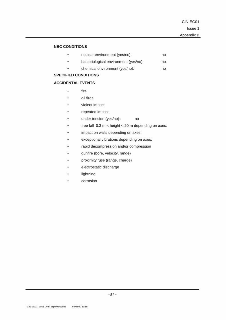
CIN-EG01
Issue 1
Appendix B
-B7 -
CIN-EG01_Ed01_AnB_sept99eng.doc 04/04/00 11:19
NBC CONDITIONS
• nuclear environment (yes/no): no
• bacteriological environment (yes/no): no
• chemical environment (yes/no): no
SPECIFIED CONDITIONS
ACCIDENTAL EVENTS
• fire
• oil fires
• violent impact
• repeated impact
• under tension (yes/no) : no
• free fall 0.3 m < height < 20 m depending on axes:
• impact on walls depending on axes:
• exceptional vibrations depending on axes:
• rapid decompression and/or compression
• gunfire (bore, velocity, range)
• proximity fuse (range, charge)
• electrostatic discharge
• lightning
• corrosion

CIN-EG01
Issue 1
Appendix B
- B 8 -
CIN-EG01_Ed01_AnB_sept99eng.doc 04/04/00 11:19
Example of table of occurrences
SituationNo.
CONTENT OF THE SITUATION Duration Occurrence
S 1 HANDLING
Loading, unloading rail, road
0.5 h 3
S 2.1 LOGISTIC ROAD TRANSPORT
From plant to storage location
8 h 3
S 2.2 LOGISTIC TRANSPORT BY RAIL
From plant to storage location
8 h 3
S 3 HANDLING
Loading, unloading rail, road
0.5 h 3
S 4.1 SHORT TERM STORAGE
Pending use
3 months 1
S 4.2 LONG TERM STORAGE
Storage on the allocation site
2 years 1
S 5 REMOVAL FROM STORAGE
Operational commissioning on the storage site
2 d 2
S 6 CORRECT OPERATION CHECK
acceptance by operators
5 d 2
S 7 EQUIPMENT AVAILABLE
pending use
12 d 360
S 8 CARRIAGE FOR TRAINING
Moved to training site
1 h 240
S 9 TRAINING TYPE OPERATING SYSTEM
System training alone, fixed station
2 d 120
S 10 CARRIED FOR MANOEUVRES
Move to allocation location for rail loading
1.5 d 24
S 11 HANDLING
Loading, unloading for rail transport
0.5 h 24
S 12 LOGISTIC RAIL TRANSPORT
Move to manoeuvres location
20 h 24

CIN-EG01
Issue 1
Appendix B
-B9 -
CIN-EG01_Ed01_AnB_sept99eng.doc 04/04/00 11:19
S 13 HANDLING
Loading, unloading for rail transport
0.5 h 24
S 14 CARRIAGE FOR MANOEUVRES
Move to unloading site for manoeuvre zone
1.5 h 24
S 15 MANOEUVRE TYPE SYSTEM OPERATION
Joint forces operation
5 d 24
S 16 CARRIAGE FOR TACTICAL USE
Tactical moving during manoeuvres
1 h 36
S 17 CARRIAGE FOR MANOEUVRES
Move from allocation site to manoeuvres site
46 h 12
S 18 CARRIAGE FOR DISPATCH OUT OF FRANCE
Move to air/sea loading/unloading site
2 to 8 h 6
S 19 HANDLING
Loading/unloading at the embarking site
2 h 6
S 20.1 LOGISTIC TRANSPORT BY SEA
Transport by container ship to port of destination
30 d 6
S 20.2 LOGISTIC TRANSPORT BY AIR
Transport to operating site outside France
48 h 6
S 21 HANDLING
Loading, unloading at the embarking or disembarking site
2 h 6
S 22 CARRIAGE TO THE OPERATING SITE OUTSIDE FRANCE
Move from the disembarking site to the operating area
4 h 6
S 23 EQUIPMENT AVAILABLE OUTSIDE FRANCE
Pending use
4 d 3
S 24 CARRIAGE TO THE OPERATING SITE OUTSIDE FRANCE
Move to the operating site 5 h
6 6
S 25 OPERATION OF THE SYSTEM OUTSIDE FRANCE
Tactical use
10 months 3
S 26 CARRIAGE FOR TACTICAL USE OUTSIDE FRANCE
Tactical move
2 h 40

CIN-EG01Issue 1
Appendix B
- B 10 -
CIN-EG01_Ed01_AnB_sept99eng.doc 04/04/00 11:19
Examples of environmental factor summary tables
Environmental factor summary table MECHANICAL ENVIRONMENT
SITUATIONS
Impa
ct
Stru
ctur
al v
ibra
tions
Con
stan
t acc
eler
atio
n
Stat
ic c
ompr
essi
on
Stat
ic d
isto
rtion
Plat
form
mot
ion
Slop
e
Acou
stic
vib
ratio
ns
Blas
t
S1 Handling �
S2.1 Logistic road transport � � �
S2.2 Logistic rail transport � � �
S3 Handling �
S4.1 Short term storageS4.2 Long term storageS5 Removal from storageS6 Correct operation checkS7 Equipment availableS8 Carriage for training � � �
S9 Training type system operationS10 Carriage for manoeuvres � � �
S11 Handling �
S12 Logistic rail transport � � �
S13 Handling �

CIN-EG01Issue 1
Appendix B
- B 11 -
CIN-EG01_Ed01_AnB_sept99eng.doc 04/04/00 11:19
Environmental factor summary table CLIMATIC ENVIRONMENT
SITUATIONS
Tem
pera
ture
Hum
idity
Sola
r rad
iatio
n
Ther
mal
sho
ck
Pres
sure
Prec
ipita
tion
Snow
Ice
Hai
l
Win
d
Sand
and
dus
t
Cor
rosi
ve a
tmos
pher
es
Flui
d co
ntam
inat
ion
Imm
ersi
on
Wat
er je
t
Mou
ld
S1 Handling � � � � � � � � �
S2.1 Logistic road transport � � � � � � � � � � �
S2.2 Logistic rail transport � � � � � � � � � � �
S3 Handling � � � � � � � � �
S4.1 Short term storage � �
S4.2 Long term storage � �
S5 Removal from storage � �
S6 Correct operation check � � � � � � � � � �
S7 Equipment available � � � � � � � � � � � �
S8 Carriage for training � � � � � � � � � � �
S9 Training type system operation � � � � � � � � � � �
S10 Carriage for manoeuvres � � � � � � � � � � �
S11 Handling � � � � � � � � �
S12 Logistic rail transport � � � � � � � � � � �
S13 Handling � � � � � � � � �

CIN-EG01Issue 1
Appendix B
- B 12 -
CIN-EG01_Ed01_AnB_sept99eng.doc 04/04/00 11:19
Environmental factor summary table ELECTROMAGNETIC ENVIRONMENT
SITUATIONS
Elec
trom
agne
tic fi
eld
Stat
ic e
lect
ricity
Nuc
lear
EMI L
ight
ning
S1 Handling �
S2.1 Logistic road transport � �
S2.2 Logistic rail transport � �
S3 Handling �
S4.1 Short term storageS4.2 Long term storageS5 Removal from storageS6 Correct operation check � �
S7 Equipment available � �
S8 Carriage for training � �
S9 Training type system operation � �
S10 Carriage for manoeuvres � �
S11 Handling �
S12 Logistic rail transport � �
S13 Handling �

CIN-EG01Issue 1
Appendix B
- B 13 -
CIN-EG01_Ed01_AnB_sept99eng.doc 04/04/00 11:19
Environmental factor summary table MISCELLANEOUS ENVIRONMENTS
SITUATIONS
Bact
erio
logi
cal
Che
mic
al
Hea
vy s
ea
S1 HandlingS2.1 Logistic road transportS2.2 Logistic rail transportS3 HandlingS4.1 Short term storageS4.2 long term storageS5 Removal from storageS6 Correct operation checkS7 Equipment availableS8 Carriage for trainingS9 Training type system operationS10 Carriage for manoeuvresS11 HandlingS12 Logistic rail transportS13 Handling
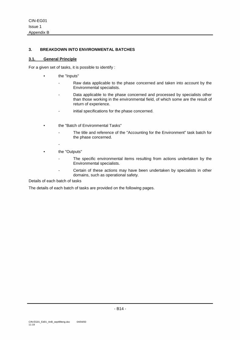
CIN-EG01Issue 1Appendix B
- B14 -
CIN-EG01_Ed01_AnB_sept99eng.doc 04/04/0011:19
3. BREAKDOWN INTO ENVIRONMENTAL BATCHES
3.1. General Principle
For a given set of tasks, it is possible to identify :
• the "Inputs"
- Raw data applicable to the phase concerned and taken into account by theEnvironmental specialists.
- Data applicable to the phase concerned and processed by specialists otherthan those working in the environmental field, of which some are the result ofreturn of experience.
- initial specifications for the phase concerned.
• the "Batch of Environmental Tasks"
- The title and reference of the "Accounting for the Environment" task batch forthe phase concerned.
-
• the "Outputs"
- The specific environmental items resulting from actions undertaken by theEnvironmental specialists.
- Certain of these actions may have been undertaken by specialists in otherdomains, such as operational safety.
Details of each batch of tasks
The details of each batch of tasks are provided on the following pages.

CIN-EG01Issue 1
Appendix B
- B15 -
CIN-EG01_Ed01_AnB_sept99eng.doc 04/04/0011:19
3.2. Accounting for the environment in the system and equipment Functional Specification
Input
• System life profile.
• Characterised operational functions (evaluation criteria and flexibility).
• Life profile – Operational functions – Evaluation criteria links.
• Broad lines and demonstrations.
• Performance broad lines regarding reliability, availability, safety, etc. for thesystem operational functions
Batch of TasksAccounting for the environment in the system and equipmentFunctional Specification
Output
• Identification of the feasibility issues which are sensitive to the environment.
• Determination of the significant environmental factors and their associatedvalues.
• Definition of the probability of failure accepted for each performance item withrespect to the environment to which it is sensitive.
• Evaluation of the technical and industrial feasibility of each concept.

CIN-EG01Issue 1Appendix B
- B16 -
CIN-EG01_Ed01_AnB_sept99eng.doc 04/04/0011:19
3.3. Accounting for the environment in the system and equipment Technical RequirementSpecification
Input
• System and equipment life profile.
• Characterised operational functions (evaluation criteria).
• Life Profile – Operational functions – Evaluation Criteria links.
• Requirements and/or objectives of the demonstrations.
• Requirements regarding reliability, availability, safety of the operationalfunctions for the system or equipment.
Batch of TasksAccounting for the environment in the system and equipmentTechnical Requirement Specification
Output
• Significant environmental factors and their associated values.
• Partitioning between normal, on-limit and extreme environments.
• Updating of the environmental values made necessary by the induced effectsof the design.
• Definition of the probability of failure accepted for each operational functionperformance item with respect to the environments to which it is sensitive.
• Updating of the specified values as a result of "in situ" measurements.

CIN-EG01Issue 1
Appendix B
- B17 -
CIN-EG01_Ed01_AnB_sept99eng.doc 04/04/0011:19
3.4. Accounting for the environment in the system and equipment design part of theDesign File
Input
• Characterised technical functions (evaluation criteria).
• Life Profile – Technical Functions (evaluation criteria) links.
• Product organisation – functional organisation links.
• Specification of the requirements in terms of sizing criteria with respect to theenvironment.
• List of design choices, technologies and manufacturing processes to reducethe sensitivity of the product to the Life Profile environment.
Batch of TasksAccounting for the environment in the system and equipmentdesign part of the Design File
Output
• List of significant environmental factors and their associated values withrespect to the SDF type functional and operational performance associatedwith the technical functions.
• Partitioning between the normal, on-limit and extreme environments.
• Sizing in relation to the environment criteria design files.
• Aggravated test design files.

CIN-EG01Issue 1Appendix B
- B18 -
CIN-EG01_Ed01_AnB_sept99eng.doc 04/04/0011:19
3.5. Accounting for the environment in the system and equipment validation during designpart of the Design File
Input
• Validation objectives and corresponding validation actions with respect to theenvironment.
• - Assumptions made for the calculations and simulations in relation to theenvironment.
• - Assumptions regarding the variability of the resistance of the performanceto environmental factors and regarding the variability of the environment.
• - Specification of the customised test severity requirements and associatedassumptions.
• - Requirements regarding reliability, availability, safety of the equipment andsystem technical functions.
Batch of TasksAccounting for the environment in the system and equipmentvalidation during design part of the Design File
Output
• Probability of failure accepted for each technical function performance itemwith respect to the environments to which it is sensitive.
• For the calculations and simulations, the environment values to be used forthe demonstrations.
• Definition of the customised test severities.
• Design Justification File for the technical functions.
• Proposed design modifications resulting in an update of the Design File.

CIN-EG01Issue 1
Appendix B
- B19 -
CIN-EG01_Ed01_AnB_sept99eng.doc 04/04/0011:19
3.6. Accounting for the environment in the Design Justification File for the system andequipment
Input
• Experience and results acquired during testing, simulation, in-situmeasurement, etc.
Batch of TasksAccounting for the environment in the Design Justification File forthe system and equipment
Output
• Justification of the variability of the environment considered for theestablishment of the sizing criteria and for establishment of the testseverities.
• Checking the content of the test documents.
• Justification that the sizing criteria do in fact meet their specification.
• Justification that the proposed test severities do in fact meet theirspecification.
• Justification that the real environment is indeed covered by the customisedtest severities.

CIN-EG01Issue 1Appendix B
- B20 -
CIN-EG01_Ed01_AnB_sept99eng.doc 04/04/0011:19
3.7. Accounting for the environment in production (Manufacturing file and inspection file)
Input
• Unfolding of the manufacturing process at the various levels of assembly.
• Capability1 of the production tools, processes, etc.
• Special requirements regarding product service life consumption resultingfrom the various inspection and debugging operations.
Batch of Tasks
Accounting for the environment in production (Manufacturing fileand inspection file)
Output
• Confirmation of the assumptions made regarding the environmental factorsand values linked to the manufacturing process.
• Proposed changes to the environmental debugging tests.
• Confirmation of the product performance variability tests with respect toenvironmental factors.
• Proposed changes to the manufacturing processes.
• Proposed changes to the product design.
• Proposed changes to the customised acceptance test severities.

CIN-EG01Issue 1
Appendix B
- B21 -
CIN-EG01_Ed01_AnB_sept99eng.doc 04/04/0011:19
3.8. Accounting for the environment during operation of the system and equipment(Operating file)
Input
• Validated life profile.
• Technical events and return of experience.
batch of Tasks
Accounting for the environment during operation of the systemand equipment (Operating file)
Output
• Enrichment of the data bases (real measured environment, technical events,etc.).
• Re-adjustment of models.
• Updating of the test methods.
• Updating of debugging.
• Proposed modification of the equipment design.

CIN-EG01Issue 1Appendix B
- B22 -
CIN-EG01_Ed01_AnB_sept99eng.doc 04/04/0011:19
• Environmental values encountered during the various phases of theprogramme and other values deduced from these (sizing criteria, testseverities, etc.).
The environmental values and the values deduced from them adopt different forms throughout thevarious phases of the programme
The table below provides an overall view, whilst specifying for each phase of the programme :
• - the corresponding level of assembly,
• - the type of function concerned (operational or technical),
• - the information required in order to convert the "input" values into "output" values,
• - any special remarks.

CIN-EG01Issue 1
Appendix B
- B 23 -
CIN-EG01_Ed01_AnB_sept99eng.doc 04/04/00 11:19
4. ENVIRONMENTAL VALUES ENCOUNTERED DURING THE VARIOUS PHASES OF A PROGRAMME AND OTHER VALUES DEDUCED FROM THESE(SIZING CRITERIA, TEST SEVERITIES ETC...)
Programme phaseEnvironmental values or values deduced from these
input output
Assemblylevel
Functions concerned
operational technical
Information required Special remarks
Feasibility leading to FunctionalSpecification
standard values taken frommanuals, data bases...fall-back valuesvalues from calculation modelsn values measured for a givenevent or situation
1 value representing each eventor situation system
�
system life profiledescription of operational functionsassumptions for behavioural modelslevel of confidence for the CVEconfidence interval
the data are described for a given situation or event, inthe form of values, sets of values (spectrum...)associated with a level of confidence and a statisticallaw, either assumed or estimated on the basis ofmeasured results.
Design leading to TechnicalRequirement Specification
previous values (FunctionalSpecification) updated with newmeasurements or evaluations ofvaluestaking into account of the effectsinduced by the design choicesindication of whether the valuebelongs to the normal, on-limit orextreme domain
identical to abovethese values constitute thespecified environmental values
all levels
�
life profile for all levels of assembly
then identical to above identical to Functional Specification
Design(leading to Design File)
environment values specified inthe Technical RequirementSpecification at the various levelsof assembly
sizing criteriaall levels
�
description of technical functionstolerated probability of failuredeterminist CVR taken frommanuals or estimated withbracketed level of confidence
the environmental values specified for a situation, anevent are synthesised by grouping together of severalevents or situations leading to the environmentalvalues adoptedthese values must be used to influence the designchoices
Development
Design validation(leading to Design
Justification File fortechnical functions)
identical to above
environmental values adopted foruse in the calculations andsimulationscustomised test severities
all levels
�
identical to above, plus :level of confidence on theconfidence level of the meanresistance of the performance itemto the environmental factorconcernednumber of identical productsamples subjected to a given test
identical to the abovethese values are used, either for calculations andsimulations, or to elaborate the customised testseverities
Development validation(leading to Design
Justification File foroperational functions)
identical to above identical to above but foroperational functions
all levels
�
identical to above but foroperational functions
identical to the above
the updated values are compared to the correspondingvalues adopted initially. In the event of exceeding them,the deduced values may be updated if necessary.
Productionenvironmental measurementscharacterising certain events inthe manufacturing process
mean synthetic values adoptedper significant event of themanufacturing processacceptance specifications
all levels
�
unfolding of the production processprobability of failure tolerated inrelation to the significantenvironments generated by theproduction process
the values synthesised per significant event of theproduction process are compared with the synthesisedvalues of the same type in the life profile. In the event ofexceeding them, the deduced values may be updated ifnecessary