Embed Size (px)
Citation preview

Chroma Systems Solutions, Inc.
Multi-Terminal Impedance Measurement, or….
Why Do Those Bridges Use so Many Connections? Precision Laboratory Measurement Instruments, Production Testing Instruments
Keywords: Impedance Measurement Error, Impedance Delta Network, Two-Terminal Measurements, Four Terminal Measurements, Four – Terminal Kelvin Measurement, Four-Terminal Measurements, Three-Terminal Measurements, Guard Lead Error, Active & Wagner Guard Measurements, Three-Terminal Bridge Measurements, Three-Terminal Measurements, Three-Terminal, Double-Guard-Lead Connection, Five-Terminal Measurements, Six-Terminal Measurements, 8-Terminal Measurements.

Application Note
© Chroma Systems Solutions, Inc. Page 2 of 21
Title:
Multi-Terminal Impedance Measurements, or ….
Why Do Those Bridges Use So Many Connections?
Scope This application note explains how the use of multiple connections can reduce or remove impedance measurement errors caused by series impedance in the connections or shunt impedance across the unknown. These techniques are important not only for precision laboratory measurements, but also in production testing, circuit troubleshooting, and process control. A particularly critical application is that of "in-situ" or in-circuit testing where the component to be measured is soldered on a printed wiring board and thus connected to many other components that could affect its measurement severely.
Many bridge users are familiar with 3- and 4-terminal techniques. Several new instruments use five connections, and some test systems use six. This note will start with two and work up to eight. First we should make it clear that in the arithmetic of counting terminals:
1 terminal = 1 wire = 1 lead = 1 connection
We only count the terminals at one end of a connecting wire: a 2-terminal bridge connected to a 2-terminal resistor by two wires makes a 2-terminal or 2-connection measurement. The terminals may be binding posts, wire leads, or pins in a connector; the arithmetic is the same.
To illustrate measurements with various numbers of terminals, we shall describe "ideal" measurements that make use of ideal voltmeters and ammeters. These meters measure DC or complex AC (i.e., real and imaginary parts), have absolute accuracy, and dissipate no power (the voltmeter has infinite impedance and the ammeter has zero impedance). Such meters, unfortunately, are not commercially available, and although modern digital meters can do quite well, most precise measurements use quite different techniques. The ideal-meter methods define each type of measurement and its theoretical result. Practical methods and actual instruments may use entirely different components and circuit

Application Note
© Chroma Systems Solutions, Inc. Page 3 of 21
configurations, but they make the same type of measurements if they get the same result (or at least very close to it).
For example, a 4-terminal bridge is a good 4-terminal bridge if it gets the same result as the ideal-meter 4-terminal method would have gotten if it could have been used. We also need a standard "unknown", a device to be tested that illustrates the capabilities of the various ideal measurement methods. The circuit chosen (Figure 1) has six terminals, that is, six places where connections may be made. It has eight impedances besides the impedance Zx whose value we desire. The choice of this circuit is not a random one, for this particular network represents several practical situations. For example, all connections will have series impedance, and therefore we might as well show some impedance (lower case z's shown as resistors) in series with each terminal.
Impedance Delta Network The inner delta network of Zx, Za, and Zb can represent several situations. It might be a three-terminal standard capacitor where Za and Zb represent stray capacitance to the case or guard (point C) or it might represent the impedance, Zx, buried in a network where Za and Zb represent actual circuit components shunting it.
Figure 1: Example Delta Network
This inner delta network could also represent any passive three-terminal network whose effective delta circuit value (short circuit transfer impedance) is desired. The reason for using more and more connections is to try to measure Zx with no errors resulting from the other eight impedances. In most cases there will be errors. In general, the measured impedance, Zm, could be expressed in the form:
x
xm CZ+1
B+A)+(1Z=Z
Zx
Za Zb
z1
z4
z3
z2
z5 z6
1 3
2 4
5 6
C

Application Note
© Chroma Systems Solutions, Inc. Page 4 of 21
where A, B and C are functions of these other eight impedances. If the measurement is accurate to any reasonable degree, A, B/Zx, and CZx must be reasonably small compared to unity. If so, we can write:
)CZZBA(1ZZ x
xxm −++≅
and the approximation is a very good one. We'll use this form for simplicity and neglect second order errors. Note that to get the errors in percent, the error terms should be multiplied by 100%. We'll see that if we use enough terminals, and some more imaginary devices, we can make a measurement on this test circuit with no error at all.
Two-Terminal Measurements Ohm’s Law defines the impedance of a device as: the ratio of the voltage across the device to the current through it. Z=V/I. This requires at least two connections and therefore the arithmetic of terminals starts with two. With only two terminals, the same terminals must be used for both applying a current and measuring a voltage as shown in Figure 2.
Figure 2: 2-Terminal Measurement
)ZZ
ZZ
z+z+(1 Z
IVZ
ba
x
x
31xm +
−==
Zx
Za Zb
z1 z31 3
2 4
5 6
A
I
V

Application Note
© Chroma Systems Solutions, Inc. Page 5 of 21
Zx = series lead error Za + Zb = shunt loading error
When our test circuit is measured in this way, the result may not be an accurate measurement of Zx as shown. (V and I are the ideal voltmeter and ammeter readings.) There are two types of errors, and these are the errors that measurements with more connections attempt to avoid. The series impedances z1 and z3 add to the measured value of impedance. They cause an error that is important when Zx is small. They add a fixed error in ohms (as opposed to percent) for their effect could be expressed as Zm = Zx + z1 + z3. If Zx could be shorted we could measure z1 and z3 and correct for them. Analogously, the shunt impedance of Za and Zb in series decreases the measured impedance. Their effect is most important when Zx is large or its reciprocal Yx (admittance) is small. We could express their error as:
bax
mm ZZ
1YZ1Y
++==
If we could open-circuit Zx, we could measure the effect of Za and Zb and correct for it. Two terminal measurements are adequate for a great many measurements. While many new instruments are capable of more sophisticated measurements, in many cases this capability is neither required nor used. Better techniques are required when the impedance to be measured is very high or very low, when high precision is required, or when series impedances or shunt admittances are unusually large.
Four-Terminal Measurements Strangely enough, 4-terminal measurements are simpler to explain than 3-terminal ones and therefore we'll jump from two to four. With a second pair of terminals available, we can measure voltage between one pair and apply current to the other as shown in Figure 3. This simple improvement removes the series lead impedance error completely and makes the four-terminal method ideal for measurements on low impedances that are negligibly affected by the remaining shunt impedance error. Unfortunately, for AC, the diagram (Figure 3) is not complete.

Application Note
© Chroma Systems Solutions, Inc. Page 6 of 21
Figure 3: Four-Terminal Measurement
)ZZ
Z(1ZIVZ
ba
xx +
−==
There will be some mutual inductance (M) between the current leads and the voltmeter leads that will add a voltage ±jωM to the voltmeter reading and ±jωM to the measured impedance. Note that the mutual inductance may have either sign depending on the lead geometry. This mutual inductance may be kept small by twisting the input current leads together, twisting the voltmeter leads together, or by doing both. It is even better to use two coaxial cables, one for the two current connections and one for the two voltage connections. Four-terminal instruments and standards often have the terminals labeled as either "current" terminals or "potential" (voltage) terminals. In theory these terminal pairs are completely interchangeable.
However, there are two situations where they are not. The first is when the current applied is very large as it might be in a four-terminal "shunt" used to measure a high current. The potential terminals aren't designed for such duty. The second situation involves the measurement device that may be more immune to lead impedance in some of its connections than in others. Usually its potential terminals can tolerate more impedance than its current terminals, although this is not always the case. The operating instructions for each specific instrument should be considered.
Four-Terminal Kelvin Measurement Four-terminal measurements have been implemented in many ways and a few are illustrated in Figure 4. The most famous of these is the Kelvin Bridge (Figure 4a) that is widely used for precision, DC resistance measurements. It has two additional bridge arms (Ra and Rb) to balance the voltage drop in the "Yoke" connection. This circuit has associated Lord Kelvin's name so closely with the 4-terminal
Zx
Za Zb
z1
z4
z3
z2
z5 z6
1 3
2 4
5 6
A
I
V

Application Note
© Chroma Systems Solutions, Inc. Page 7 of 21
technique that we often use the term "Kelvin" in place of "four-terminal". We may talk of a Kelvin measurement or a Kelvin connection even though we don't mean to refer to the actual Kelvin bridge circuit.
The potentiometer method (Figure 4b) uses several voltage ratio measurements and a calculation. A 4-terminal impedance can also be determined from a series of four 2-terminal measurements. Generally, successive measurements with simple connections and appropriate calculations can give the same results as the more complicated methods. For example, Zx in Figure 1 may be determined exactly by making nine 2-terminal measurements or three 4-terminal ones.
With AC, transformers may be used to inject compensating voltages in appropriate places to reduce errors as is done in the circuit of Figure 4c. The voltage drop (Ey) in the connection between the low impedance ratio arm Ra and the unknown Cx is injected between the other two high-impedance arms thus canceling its effect. Most new, four-terminal instruments use precision, high-input-impedance differential amplifiers to allow the measurement of the voltage across the unknown with negligible effect from series impedance (Figure 4d).
Figure 4a: Kelvin Bridge
CBA
α
D
RSRX
Precision Voltage Divider
RX =αa - αb
RS αc - αd

Application Note
© Chroma Systems Solutions, Inc. Page 8 of 21
Figure 4b: Potentiometer Method
Figure 4c: Transformer Compensation
Figure 4d: Differential Amplifiers
CBA
α
D
RSRX
Precision Voltage Divider
RX =αa - αb
RS αc - αd
CXCS
Rn Ra
EY EY
Voltage drop EY appliedto opposite bridge armsby means of 1:1transformer.
ZX
RS
Diff Amp
Diff Amp
To a RatioDevice
High input impedancedifferential amplifiersgive ground referencedvoltages independent oflead impedance

Application Note
© Chroma Systems Solutions, Inc. Page 9 of 21
Three-Terminal Measurements While the four-terminal measurement applies a current and measures the resulting open-circuit voltage, the three-terminal measurement does just the opposite; it applies a voltage and measures the resulting short-circuit current (Figure 5). To do this, it uses an extra terminal: a common connection between the input voltage and output current. Impedances from either terminal of Zx to this third terminal have no effect (if the series lead impedances are zero). Impedances will load the input, but even if it reduces the voltage, the voltmeter reading is still valid. Impedance shunting the ideal ammeter has no effect because the ammeter has zero impedance. This third terminal is called the guard. The effect of any stray path, capacitive or conductive, (shunting Zx) can be removed by intercepting it with a shield tied to the guard point. Likewise, “shunting Zx” can effectively be removed in a series string of actual components by connecting some point along the string to the guard and making a three-terminal measurement. Sometimes three-terminal measurements are simply called guarded measurements. They are also called direct impedance measurements. Figure 5 illustrates one representation of a passive 3-terminal network.
ba
x5
b
3
a
1
x
31xm ZZ
ZzZz
Zz
Zzz
(1ZIVZ −++
++≅= )
Figure 5: 3-Terminal Measurement
The impedance Zx is that impedance directly between points A and B. As shown by the formula for Figure 5, errors caused by Za and Zb have been changed. If it were not for the series impedances, the effect of Za and Zb would have been removed completely. The combination of series impedance and shunt impedance has given us two new types of errors. We'll call the first (z1/Za and z3/Zb) the "series/shunt" error. It's caused by a voltage, or current, divider effect. The voltage between point A and guard is reduced because the attenuating or dividing effect of the impedances z1 and Za. Likewise, Zb and z3 divide the current Ix so that it doesn't all flow in the ammeter. Note that this error is a constant percent error, independent of the value of Zx. It usually is very small at low frequencies unless the series and shunt impedances are actual circuit components as they might be in in-circuit measurements.
Zx
Za Zb
z1 z3
z5
A
V A
B
C

Application Note
© Chroma Systems Solutions, Inc. Page 10 of 21
Guard Lead Error The second new type of error (the last term) is the "guard-lead error". It can become important when Zx is very large, but it is (generally) much smaller than the shunt error of Figures 2 and 3 because the ratio z5/Za is usually very small. This error can most easily be explained by making a Y to delta transformation of the Y network formed by Za, Zb, and z5. The result gives an impedance value:
5
baba z
ZZZZ ++ (directly across Zx).
Since the last term is by far the largest ignore the first two and thus the shunt error term is:
ba
x5
ZZZz−
One situation in which the guard lead error is noticeable is the precision measurement of low-loss 3-terminal capacitors using long, shielded leads. Here the impedances Za and Zb are capacitances (Ca and Cb) that can be quite large. Any resistance in the guard connection (r5) causes a negative resistance across the capacitor being measured:
5ba
25
ba
rCC1
zZZ
ω−
=
This can give a negative conductance or dissipation factor bridge reading that has bewildered many a metrologist. For in-circuit testing, this error can be very important; for example, if Za and Zb are 100Ω resistors, the effective impedance shunting Zx is 10kΩ if the lead impedance is only 10mΩ. Many traditional four-arm capacitance bridges (such as that of Figure 6a) make fair three-terminal measurements because they will tolerate some loading across the standard capacitor without excessive error and because loading across the source (or detector) causes no errors directly (it only reduces sensitivity).
Application Note
© Chroma Systems Solutions, Inc. Page 11 of 21
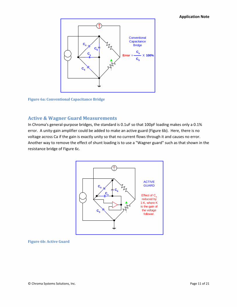
Figure 6a: Conventional Capacitance Bridge
Active & Wagner Guard Measurements In Chroma's general-purpose bridges, the standard is 0.1uF so that 100pF loading makes only a 0.1% error. A unity-gain amplifier could be added to make an active guard (Figure 6b). Here, there is no voltage across Ca if the gain is exactly unity so that no current flows through it and causes no error. Another way to remove the effect of shunt loading is to use a "Wagner guard" such as that shown in the resistance bridge of Figure 6c.
Figure 6b: Active Guard
Ca
Cb
Error
ConventionalCapacitance
Bridge
CS
CX
= X 100%Ca
CS
ACTIVEGUARD
Ca
Cb
CS
CX
Effect of Careduced by
1:K, where Kis the gain ofthe voltagefollower.

Application Note
© Chroma Systems Solutions, Inc. Page 12 of 21
Figure 6c: Wheatstone Bridge with Wagner Guard
If the auxiliary balance (Rp) is made, Ra and Rb have no effect. Similar guard circuits have been used in commercial bridges.
Three-Terminal Bridge Measurements However, most precision AC bridges now use tightly coupled transformers (Figure 6d) to give both precise ratios and good immunity from shunt loading. If the voltage of one output winding of the transformer is reduced loading, the voltage on the other is reduced also because of the coupling between them.
Figure 6d: Transformer Ratio Arm Bridge
The effective output impedance of each winding is only its resistance and the leakage inductance, and these can be very small if the transformer is properly designed. A modified transformer connection (Figure 6e) has no loading errors because Ca shunts the source and Cb the detector so that they cause
Rq
RtRn
RXRb
RS
Ra
Rp
A
B
Guard
Switch to A:Balance Rp
Switch to B:Balance Rn
WheatstoneBridgewith
WagnerGuard
CX
CbCa
CS
Tightcouplingallowsheavy
loading
TransformerRatioArm
Bridge

Application Note
© Chroma Systems Solutions, Inc. Page 13 of 21
only a loss of sensitivity. An analogous active bridge is shown in Figure 6f. The accuracy of both these bridges depends on the accuracy of the inverting device, transformer or op amp inverter.
Figure 6e: Lynch Bridge Figure 6f: Active Bridge
Three-Terminal Measurements Chroma's newer digital meters use an inverting amplifier and resistor as a current-to-voltage converter (Figure 6g). This amplifier puts its input (A) to a "virtual ground", that is, it brings this point very nearly to ground potential. The effective impedance to ground is the feedback resistance (Rs) divided by the amplifier open-loop gain. The error from shunting capacitance (Cb) can be quite small.
Figure 6g: 3-Terminal Meter Circuit
CX
CbCa
CS
CX
CbCa
CS
3-TerminalBridgesthat can
withstandextremeloading
LynchBridge
ActiveBridge
CX
CbCa
RS
V1
V2
A
+
-
Gain = K
3-TerminalMeterCircuit
with activecurrent tovoltage
converter
Error caused by CbK
ωRSCb= 100%

Application Note
© Chroma Systems Solutions, Inc. Page 14 of 21
Three-Terminal, Double-Guard-Lead Connection The guard lead error of Figure 5 can be removed by using two guard connections as illustrated in Figure 7. (This results in a total of four connections, but let's not call it a four-terminal measurement. We'll reserve that for the "Kelvin" type measurement.)
b
63
a
51
x
6531xm Z
zzZ
zzZ
zzzz(1Z
IVZ
+=
++
++++≅= )
Figure 7: 3-Terminal, Double Guard
More Double Guard Measurements The ‘double guard’ connection simply puts the guard lead impedances in series with the other lead impedances. There is no shunt error at all and therefore this method is excellent for very high impedance measurements. A possible capacitance bridge making use of the double guard lead is shown in Figure 8a. This circuit takes advantage of the isolating ability of a transformer as well as its other features. It puts one guard impedance, z5, in series with z1 and the other, z6, in series with z3.
Zx
Za Zb
z1 z3
z5
A
V A
B
C
5 6
42
31
z6
3-Terminal Double Guard
If YX = 0, then Ym = 0

Application Note
© Chroma Systems Solutions, Inc. Page 15 of 21
Figure 8a: Transformer Ratio Arm Bridge in Double Guard Connection
The active circuit of Figure 8b is used in a DC bridge used in large systems that have relatively high lead impedances because the connections are switched and the wires are long. The inverting amplifier puts point P at a virtual ground. This effectively reduces the guard lead impedance by the gain of the amplifier.
Figure 8b: Active Guard Circuit
The meter circuit of Figure 6g can form a double guard lead circuit if the grounding is modified to allow two guard connections. This may be accomplished by added an isolating transformer (Figure 8c) or simply by lifting the amplifier ground, thus putting z6 in series with this high impedance input (Figure 8d).
CX
CbCa
CS
Connectedto giveDoubleGuard
Connection
TransformerRatioArm
Bridge
z1 z3
z5
z6
Zx
Za Zb
P
Zx
Za Zb
Z'
V AAV
Gain = KZ ' =
1 + K
z6
z6z5

Application Note
© Chroma Systems Solutions, Inc. Page 16 of 21
Figure 8c: Isolating Transformer
Figure 8d: Modified Inverter
Five-Terminal Measurements When both the three-terminal and four-terminal techniques are combined, as in Figure 9, the result is a total of five terminals, not seven. The term "five terminal" is not widely used, but it should be more common in the future because most new measuring instruments have this capability. The main reason they have it is so that they can make measurements over a very wide range of impedances. They need the four-terminal capability for low impedances and three-terminal capability for high impedances, particularly small capacitances. It is relatively rare to require both capabilities for a single measurement except for extremely precise measurements, remote measurements, or in-circuit measurements. This technique has neither of the original two-terminal errors and is left with only much smaller errors caused by the interaction of series and shunt impedances.
CX
CbCa
z6
RS
z5
+
-
CX
CbCa
z6
RS
z5
+
-

Application Note
© Chroma Systems Solutions, Inc. Page 17 of 21
ba
x5
b
3xm ZZ
ZzZz
(1ZIVZ −+≅= )
Figure 9: Five-Terminal Measurement
The Chroma digital impedance meters make a five-terminal measurement by means of the circuit of Figure 10a. This uses the differential amplifiers and the inverter in previous circuits.
Figure 10a: Active 5-Terminal Meter Circuit
A passive five-terminal bridge is shown in Figure 10b. This is an AC version of the 4-terminal Kelvin bridge that uses transformers whose effective low impedance provides good three-terminal capability.
I-
EX
ES
CX
Cb
Ca
I+
-
+
P-
P+
RS
DifferentialAmplifiers
ES
EX
RS
ZX=
3-Terminal + 4-Terminal = 5-TerminalZx
Za Zbz1 z3
z5
A
V
A
B
C
5
42
31
5-Terminal Measurement

Application Note
© Chroma Systems Solutions, Inc. Page 18 of 21
Figure 10b: Hill’s Transformer Bridge (AC Version of Kelvin Bridge)
Six-Terminal Measurements The next step is obvious. If we use the double-guard technique with the five-terminal method, we have a "six-terminal" measurement that avoids guard lead errors (Figure 11).
Figure 11: 6-Terminal Measurement
)Z
zz(1Z
IVZ
b
63xm
++==
The only error left is a series/shunt error which was the least important type of error of all those considered. Six-terminal measurement circuits can be formed by adding the active circuit of Figure 8b to any five-terminal circuit or by modifying the active five-terminal circuit of Figure 10a by adding an isolation transformer as in Figure 8c or using the modified inverter connection of Figure 8d. The latter is shown in Figure 12 along with its error formula.
Zx
Za Zb
Yoke
ZS
Zx
Za Zbz3
42
31
z6 A
V
65
5-Terminal + extra guard lead = 6-Terminal

Application Note
© Chroma Systems Solutions, Inc. Page 19 of 21
)ZK)Z(1
ZzK)Z(1
RZz
(1ZZ
EE
ba
x5
b
s
b
3
s
x
s
x
+−
+++=
Figure 12: 6-Terminal Method
Figure 12 combines 3-terminal double guard and 4-terminal methods. Only a very few instruments make use of a six-terminal connection. An application where the six-terminal connection is particularly useful is for testing components assembled on a printed circuit board.
How About Eight Terminals? While the five-and six-terminal methods should be adequate for almost everyone, there is always somebody who is not satisfied. At the National Institute of Standards and Technology they talk about
accuracies better than a part in 108, and to get down there requires even more terminals. They have developed a four-terminal-pair method (outlined in Figure 13), and four pairs equals eight terminals. Our previous measurements use imaginary meters. In this one we have to make imaginary adjustment as well. If one were to adjust a second voltage, E2, (synchronous with E1) until the null detector indicated zero voltage, then no voltage appears across Zb so that the ideal voltmeter reads the voltage across Zx exactly, and no current flows in Zb or in the null detector so that all the current Ix flows in the ammeter.
The ratio of the reading is Zx exactly with no error. The NIST system uses shielded coaxial connections to avoid errors caused by mutual inductance and electrostatic and electromagnetic pickup. These shielded leads have effective shunt impedance at both ends while in our test circuit Za and Zb represent only shunt impedance at the ends of the cables tied to Zx. If impedance at the other ends of the cables is added, this method has slight series/shunt type errors as indicated by the formula given in Figure 13.
Zx
Za Zb -
+
ESEX
RSz3
z4z2z1
z6z5 Voltage Gain = K

Application Note
© Chroma Systems Solutions, Inc. Page 20 of 21
(Here Z26 is between terminals #2 and #6, etc.). These errors are relatively small and, moreover, can be easily determined and accounted for.
)Z
zzZ
zz(1ZZ
37
73
26
62xm
+−
+−=
Figure 13: 8- Terminal Measurement (4-Terminal-Pairs)
While a realization of this coaxial, four-pair method in actual hardware is beyond the intended scope of this note, a modified, six-terminal version of the method is practical. To obtain this circuit (Figure 14) one should note the following changes from Figure 13: 1) At null, there is no current in connections #6 and #8 so that they can be combined without error. 2) Voltage drops in leads #5 and #7 have no effect so that these leads may be combined. 3) The voltmeter could be just as well be placed between terminals #2 and # 4, (terminals 6, 8, and 4 are all at the same potential at null). And 4) an op amp can replace the null detector-adjustable source combination because, with negative feedback, the output of an op amp brings its input to (almost) zero volts (i.e., a "null"). The result, Figure 14, is very close to the six-terminal circuit of Figure 12, the differences being the inclusion of z3 in the feedback path and the dual use of terminal #4. Note that for the new circuit, as drawn, there is no error if the op amp has infinite gain.
Zx
Za Zb
42
31
6
5
8
7
A
V
IXI
E1 E2
NullDetector
AdjustableSource
Adjust E2 to give anull on null detector
Zm = ZXVI at null =

Application Note
© Chroma Systems Solutions, Inc. Page 21 of 21
Alternate 6-Terminal Measurement
)ZK)Z(1
ZzK)Z(1
RZz
(1ZZ
EE
ba
x5
b
s
b
3
s
x
s
x
+−
+++=
Figure 14: Alternate 6-Terminal Circuit
Conclusion While some of the ideal methods shown were completely immune to series or shunt impedances, actual measuring instruments can never be. Nothing real is perfect. The degree of immunity of actual circuits varies widely as does the degree of immunity required for different applications. A precision resistance bridge which has negligible error from 1Ω in each lead is a good four-terminal bridge for measuring resistors because test leads and connections usually have much less resistance than 1Ω. Likewise a capacitance bridge immune to 1000pF of shunt loading is perfectly adequate for three-terminal measurements on capacitors. If the unknown is remotely located from the measuring instrument so that long leads are required, both series resistance and shunt capacitance will increase, and better immunity is required. The most difficult multi-terminal measurements are in-circuit measurements where the series and shunt impedances are actual circuit components that may be of any value. It is easy to imagine component values in the test circuit of Figure 1 that would make it impossible to measure Zx accurately with any available instrument. However, instruments are available that can measure all but a few percent of the components in a typical printed circuit board. Because different applications require different degrees of immunity, simply saying that an instrument has three-terminal or four-terminal capability is not sufficient. Some measure of these capabilities should be incorporated in its specifications.
Zx
Za Zb -
+
ESEX
RS
z3
z4z2
z1
z6z5 Voltage Gain = K
2
1
4
3