Embed Size (px)
Citation preview

Abstract—Recent advancements in Ku-band high throughput
satellites (HTS) will allow commercial Ku-band aeronautical mobile satellite systems (AMSS) to equal or exceed commercial Ka-band AMSS systems on cost and performance.
The AMSS market is currently dominated by Ku-band solutions, both in the commercial sector (eXConnect, Row44, Yonder) and the government sector (Tachyon, Boeing Broadband Satellite Network (formerly Connexion), various UAV and ISR systems). All of these systems use conventional continental-scale wide beams that are leased from Fixed Satellite Service (FSS) providers such as Intelsat and Eutelsat.
In the next several years the dominance of Ku-band AMSS will be challenged by Ka-band systems such as Inmarsat-5, which use multiple spot beams to offer enhanced performance. Previous work has suggested that these systems may offer better performance and better economics than conventional Ku-band systems [1].
The key insight of this paper is that the performance advantage of spot beam Ka-band systems comes from their smaller beam size rather than their frequency of operation, meaning that a Ku-band spot beam satellite can also be built with similar sized spot beams to Ka-band systems and can achieve competitive cost and performance as compared to a Ka-band spot beam systems. High throughput spot beam Ku-band systems, such as Intelsat’s EpicNG system, are now in development and will be fielded in the same timeframe as Inmarsat-5.
This result has critical implications for existing users and operators of AMSS systems:
-‐ Currently installed Ku-band terminals will be able to take advantage of dramatic improvements in performance when high throughput Ku-band becomes available -‐ Current Ku-band will not have to undergo costly Ka-band
retrofits to maintain competitive performance -‐ Operators can continue to invest in Ku-band terminals today
without fear of obsolescence in the near future -‐ The AMSS market will continue to be diverse and competitive
for years to come
Index Terms—HTS, Aeronautical, Mobile, Ka-band, Ku-band
I. INTRODUCTION ERONAUTICAL mobile satellite systems in the Ku-band have become commonplace in commercial and
government applications over the past 12 years. Commercial applications include in-flight internet service for passenger airliners and executive jets, rebroadcast TV service, content distribution for in-flight entertainment systems, back haul for in-flight cellular systems, aircraft operational data, and electronic flight bag updates. Government applications include internet and voice service for executive aircraft, ISR back haul
C. McLain and S. Panthi are with Panasonic Avionics Corporation. M. Sturza and J. Hetrick are with LinQuest Corporation
for manned and unmanned aircraft, and in-route mission updates for Special Forces aircraft.
A half dozen companies have built and currently operate Ku-band AMSS systems. While based on different terminal and modem technologies, these systems share certain common technical characteristics. All of these systems use bent-pipe transponders that are leased from FSS providers. Most FSS satellites employ beams that are several thousand km across – on the scale of a continent – with an equivalent beam diameter of around 5°. A single beam might cover an area the size of CONUS, the North Atlantic, or Europe and the Middle East. Normally these beams are used to support video distribution or Very Small Aperture Terminal (VSAT) data networks that span large areas. The edge G/T of these beams is often low, -1 dB/K to +1 dB/K, so relatively bandwidth inefficient spread spectrum waveforms are required for use with small aeronautical terminals. Downlink EIRPs are also modest, 48 dBW to 50 dBW over typical bandwidths of 27 MHz or 36 MHz, limiting the total downlink throughput per transponder. Nevertheless, these systems have been quite successful because it is possible to lease small amounts of transponder bandwidth to establish a network and then only expand when demand justifies it. To the degree that barriers to entry exist, they are in the development and installation of the terminals in the aeronautical environment, which is very challenging.
The current dominance of Ku-band in the AMSS broadband market will be challenged by future Ka-band systems such as Inmarsat-5. These satellites are purpose built for mobile service and involve large upfront capital investments. They use spot beams with diameters around 2° – roughly one sixth the area of a conventional Ku-band satellite. Smaller beams yield higher satellite antenna gain and edge G/T‘s on the order of 9 dB/K, which enable higher spectral efficiencies and uplink data rates. Smaller beams also increase beam EIRP without increasing satellite amplifier size, allowing higher downlink throughputs. While the launch of these satellites and the availability of Ka-band terminals is a number of years away, the promise of higher throughputs and data rates is a powerful marketing tool for Ka-band AMSS. Ka-band providers have a vested interest in portraying Ka-band as the future of AMSS.
This paper shows that the supposed performance advantages of Ka-band have nothing to do with the frequency band and everything to do with the spot beam size. A key factor here is that, for a given spot beam size, the associated antenna gain is the same, independent of frequency. While the same sized spot beam requires a larger satellite antenna at Ku-band as compared to Ka-band, creating beams smaller than 2° is
High Throughput Ku-band Satellites for Aeronautical Applications
Chris McLain, Sunil Panthi, Mark Sturza, and James Hetrick
A

relatively easy at Ku-band. This means that the performance advantage of spot beam Ka-band payloads are equally applicable at Ku-band frequencies. Ku-band satellite providers are now responding by developing plans to deploy spot beam systems with higher throughputs, such as Intelsat’s EpicNG system.
The following technical discussion illustrates why a Ku-band spot beam meets or exceeds the performance of a similarly sized Ka-band spot beam. We then discuss the implications of this result, including an overview of Ku-band high-throughput spot beam satellites that are being developed to challenge the Ka-band spot systems, and how these systems will affect AMSS users and operators.
II. TECHNICAL DISCUSSION This section assesses the technical differences between Ka-
band and Ku-band and derives the relative performances given equivalent spot beam sizes.
A. Frequency Bands The ITU defines Ku-band as the frequency range 12 – 18
GHz and Ka-band as the frequency range 27 – 40 GHz [2]. The “u” in Ku means the band under K-band and the “a” in Ka the band above K-band. For commercial satellite communications systems, Ku-band, also known as the 14/12-GHz band, and Ka-band, also known as the 30/20-GHz band, generally have the frequency ranges shown in Table 1. The specific spectrum available for providing aeronautical broadband service varies by system and by region.
Table 1 Satellite Communication (SATCOM) Band
Frequencies
Band Alternate Designation
Uplink Frequencies
Downlink Frequencies
Ku 14/12 12.75–14.5 GHz 10.7–12.75 GHz Ka 30/20 27.5–30 GHz 17.7–20.2 GHz
For purposes of this assessment, Ku-band is assumed to have uplinks at 14 GHz and downlinks at 12 GHz, and Ka-band is assumed to have uplinks at 30 GHz and downlinks at 20 GHz. The exact frequencies used by a given system will not materially impact this assessment.
B. Link Budgets A key performance metric of any satellite link is the
achievable spectral efficiency, expressed in units of bps/Hz. The higher the efficiency, the more data bits can be delivered in a given bandwidth. Spectral efficiency is related to carrier-to-noise power ratio (C/N) by the Shannon bound:
𝜀 = 𝑙𝑜𝑔! 1 + 𝐶/𝑁 (1) High performance modulation and coding schemes, such as
DVB-S2 (with a 0.2 roll-off factor), operate near 60% of the Shannon bound. Also, satellite links experience interference in addition to thermal noise. Thus, realizable spectral efficiency is given by: ε = 0.6×log! 1 + C/(N + I) (2)
The C/(N+I) for a transponded satellite link is given by:
!!!!
= !!
!! !"
! !!! !"
! !!! !"#
! !!! !!"
(3)
Where (C/N)UL is the uplink C/N due to thermal noise at the satellite
(C/N)DL is the downlink C/N due to thermal noise at the terminal
(C/I)ASI is the C/I due to adjacent satellite interference (C/I)CCI is the C/I due to co-channel interference from
frequency reuse in other beams For a well-designed satellite system, the satellite-to-user
(C/N)DL will dominate the forward link C/(N+I) and the user-to-satellite (C/N)UL will dominate the return link C/(N+I). Typical values for (C/I)ASI and (C/I)CCI are 18 dB and 18 dB, respectively. Good practice is to design the gateway-satellite segment C/N’s such that they do not degrade the user-satellite segment C/N’s by more than 0.5 dB. Then for the forward link:
!!!! !"
= !!
!.!"× !! !"
!!.!"# (4)
And for the return link
!!!! !"
= !!
!.!"× !! !"
!!.!"# (5)
C. Forward Links (Gateway to Aircraft) The forward link (C/N)DL is given by:
!! !"
= !"#!"×!!×!
(6)
Where PFDDL is the downlink power flux density at the Earth’s surface (W/m2/Hz)
A is the effective area of the terminal antenna (m2) k is Boltzmann’s constant (-228.6 dBW/K/Hz) T is the terminals receiver noise temperature (K). To make results comparable between the Ku-band and Ka-
band we assume both transmit a PFD of -179 dBW/m2/Hz. This is the average PFD produced in a 2° spot beam by a 36 MHz transponder powered by a 100 W amplifier assuming 2 dB of feed loss. Since satellite costs are roughly proportional to satellite power and coverage area is proportional to beam size, this assumption is equivalent to assuming that the Ku-band and Ka-band satellites have similar costs and coverage areas.
Assuming a 0.45-m diameter terminal antenna and typical noise figures of 1.9 dB for Ku-band and 4 dB for Ka-band terminals, the results are shown in Table 2. Ka-band has a 4.4 dB lower downlink C/N and a 1.7 dB lower forward link C/(N+I) primarily as a result of the higher noise figure of the Ka-band receiver. The ultimate result is similar but has slightly lower spectral efficiency for Ka-band. Thus, given equal costs and coverage areas, Ku-band will have similar or even slightly better forward link performance.

Table 2 Forward Link Performance Ku-‐Band Ka-‐Band PFD Limit (dBW/m2/Hz) -‐179 -‐179 Noise Temperature (K) 159 438 (C/N)DL (dB) 19.6 15.2 C/(N+I) (dB) 13.6 11.9 ε (bps/Hz) 2.7 2.4
D. Return Links (Aircraft to Gateway) The return link (C/N)UL is given by:
!! !"
= !"#$!×!!×!×!
(7)
Where EIRP0 is the terminals EIRP density (W/Hz) G is the satellite antenna gain L is the free space loss from the terminal to the satellite k is Boltzmann’s constant (-‐228.6 dBW/K/Hz) T is the satellite receiver noise temperature (K). The EIRP0 values can be obtained from the off-‐axis EIRP density emission limits by assuming a standard antenna pattern. The off-‐axis EIRP density emission limits are shown in Table 3.[3][4]
Table 3 Off-Axis EIRP Density Limits Band Off-‐Axis Angle EIRP Density Limit Ku 2.5° ≤ φ ≤ 7° -‐13 – 25 x log(φ) dBW/Hz Ka 2° ≤ φ ≤ 7° -‐27 – 25 x log(φ) dBW/Hz
The values in Table 3 specify the maximum amount of
transmit power as a function of off-axis angle. First, note that the off-axis EIRP limits for Ku-band are substantially higher than for Ka-band. This consideration is at least partially off-set by the higher directivities that are achievable for Ka-band antennas of the same size. The key question is whether, in net, the regulations favor one of the bands. Figure 1 answers this question by showing the power spectral density for two assumed transmit patterns, representative of the same size antenna, 0.45 m, operating at Ku-band and Ka-band. In order to generate Figure 1 we created antenna patterns using standard Bessel functions and scaled the transmitter power until the Ku-band and Ka-band transmit patterns just touched the applicable regulatory mask.
By looking at the peak power spectral density (at 0° off-axis from electrical boresight) we can see that the Ku-band antenna is allowed to transmit an EIRP approximately 6 dB higher, indicating that, with all other factors being equal, regulatory transmit limits favor the Ku-band.
Given the spectral density values above, the return link performance is shown in Table 4 for a 40.1 dBi satellite receive antenna gain based on a 2° spot beam, 273 K Earth temperature, and noise figures of 1.9 dB and 4 dB for satellite receivers at Ku-band and Ka-band, respectively. The result is a spectral efficiency for Ku-band that nearly doubles that for Ka-band. This is a consequence of the higher off-axis ESD limits in the Ku-band and lower space loss. For equivalent size spot beams, the return link performance at Ku-band will in
fact substantially exceed that of Ka-band.
Figure 1 Transmit PSD for 0.45 m Antennas vs.
Regulatory Limits
Table 4 Return Link Performance Ku-‐Band Ka-‐Band EIRP0 (dBW/Hz) -‐13 -‐19 GSAT (dBi) 40.1 40.1 L (dB) 207.3 213.7 TSAT (K) 432 711 (C/N)UL (dB) 22.0 7.5 C/(N+I) (dB) 14.1 6.4 ε (bps/Hz) 2.8 1.5
E. Architecture Considerations While existing Ku-band systems tend to have wider beams
than Ka-band systems, this is more a result of the Ku-band system architectures being developed earlier in time when demand was geographically sparse rather than as a result of any engineering or regulatory considerations. Spot beams have been used in Ku-band for point-to-point trunking of data since the launch of the Intelsat V series satellites in 1981. However, the dominant market for Ku-band in recent years has been video distribution and widely dispersed VSAT systems. Even when Ku-band beams have been developed for mobile services, they have been designed to provide wide coverage for relatively low traffic density services. Only with rising demand has it been possible to justify spot beam systems, whether in Ku- or Ka-band, for mobile services.
For a given spot beam footprint on the Earth, the required area of a Ka-band satellite antenna is only 36% of that required at Ku-band for transmit (downlink) and only 22% for receive (uplink). This suggests that significantly less satellite real estate is required at Ka-band. However, the absolute aperture area required to produce a 2° mobility beam in either band is not that great. To generate a receive beam only requires a 0.5 m antenna diameter at Ka-band and 1.0m at Ku-band. Current satellites can support deployable rigid reflectors of up to 2.6 m, so these sizes are both small relative to the limits of feasibility for basic satellite antennas.
If a separate aperture were used for each beam even these small reflectors would consume a large amount of real estate
-‐60
-‐50
-‐40
-‐30
-‐20
-‐10
0
0 2 4 6 8 10
Power Sp
ectral Den
sity (dBW
/Hz)
Degrees off of EBS (deg.)
Ku Reg. Limit
Ka Reg. Limit
Ku PSD
Ka PSD
to support a large number of spots. However, regardless of frequency band, satellite antenna systems are designed to reuse apertures by using multiple feeds. This has been very effectively done at L- and S-band where GEO Mobiles such as Thuraya and TerreStar operate hundreds of spot beams. Compare this to Ka-band systems such as Inmarsat-5 (Global Xpress) with 89 beams and ViaSat-1 with 72 beams. There is no engineering reason why Ku-band systems cannot be constructed with similar numbers of beams and, in fact, examples such as IPstar-1 (Thaicom-4) with 84 Ku-band spot beams already exist. In most cases, both Ku-band and Ka-band satellites will use 2, 3 or 4 antennas to generate 40 to 80 spots and provide adequate spacing between reflector feeds.
The band in which satellite operators choose to operate is largely dictated by their access to spectrum rather than by the advantages of the particular band. Ku-band is relatively crowded. Operators who do not have coordinated Ku-band orbital slots, such as ViaSat and Inmarsat, look to use Ka-band. Operators, such as Intelsat and SES, who have significant numbers of coordinated Ku-band slots can typically coordinate spot beams without a problem.
F. Propagation Effects Propagation effects due to the atmosphere are more
pronounced in Ka-band than in Ku-band. However, since aircraft cruise altitudes are well above most weather, the airplane-satellite links are not significantly impacted by propagation effects, regardless of the frequency band used.
The gateway-satellite links are, however, impacted by propagation effects, the most significant of which is rain attenuation. Table 5 shows the rain margin required as a function of availability for a gateway at a typical teleport location. While the margins required for 99.99% availability in Ku-band are achievable, those required at Ka-band are not realistic. Site diversity for Ka-band gateway antennas (e.g. 20 to 50 km apart) could be used to mitigate heavy fade condition, but will add to the cost and overall operational complexity of the system.
Table 5 Rain Margin Required at Specified Availability Availability 99% 99.9% 99.99% Outage (hours) 87 8.7 0.87 Ku-‐Band
Uplink < 0.1 dB 1.1 dB 10.4 dB Downlink < 0.1 dB 0.7 dB 7.5 dB
Ka-‐Band
Uplink 0.3 dB 5.9 dB 41.7 dB Downlink 0.1 dB 2.6 dB 20.9 dB
III. SYSTEMS UNDER DEVELOPMENT The technical demonstration that high throughput Ku-band
AMSS systems can equal or exceed the performance of Ka-band systems is particularly interesting because such Ku-band systems are now in development. This section details Panasonic’s commitment to the new Intesat EpicNG platform and the performance it can deliver to common government aeronautical platforms.
A. Panasonic and Intelsat EpicNG Panasonic Avionics Corporation announced its intention to
develop a high throughput aeronautical Ku-band system to expand on its current conventional Ku-band offering in March, 2012. In July, 2012, Panasonic and Intelsat announced an agreement for up to 1 Gbps of high throughput capacity on Intelsat-29e, the first of Intelsat’s EpicNG satellites. This capacity will be dedicated for aeronautical users. EpicNG is Intelsat’s new high-performance, open-architecture satellite platform, which in addition to supporting aero services, uses Ku-band spot beams and wide beams to serve the media, broadband, government and mobility sectors. As part of this agreement, a portion of the capacity on Intelsat-29e was customized for serving the aeronautical market and in particular the high density routes in North America and the North Atlantic. Future EpicNG satellites will expand on this coverage area.
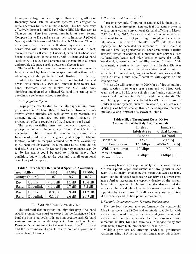
Intelsat-29e will support up to 200 Mbps of throughput in a single location (160 Mbps spot beam and 40 Mbps wide beam) and up to 80 Mbps to a single aircraft using commercial aeronautical terminals intended for wide body aircraft. The high throughputs supportable by Intelsat-29e exceed those of similar Ka-band systems, such as Inmarsat-5, as a direct result of using spot beams smaller than 2°. A comparison between Intelsat-29e and Inmarsat-5 is shown in Table 6.
Table 6 High Throughput Ku vs. Ka for Commercial Wide Body Aero Terminals.
Intelsat Intelsat-‐29e
Inmarsat Global Xpress
Ku-‐band Ka-‐band Beam size << 2° 2.1° [5] Spot beam down 160 Mbps 42-‐84 Mbps [6] Wide beam down 40 Mbps NA Max Terminal Transmit Rate 4 Mbps 4 Mbps [6]
By using beams with approximately half the area, Intelsat-
29e can support larger bandwidths and throughputs in each beam. Additionally, smaller beams mean that twice as many beams can be allocated to focusing capacity on a given area, hence further increasing the capacity density of the system. Panasonic’s capacity is focused on the densest aviation regions in the world while low density regions continue to be supported by wide beams. This allows a very high utilization of the capacity and the best possible economics.
B. Example Government Aero Terminal Performance The previous section gave performance for commercial
AMSS service using IS-29e and terminals suitable for wide body aircraft. While there are a variety of government wide body aircraft terminals in service, there are also much more numerous smaller Ku-band terminals in service today that could benefit from high throughput Ku-band AMSS.
Multiple providers are offering service to government customers using 11.5 inch to 18 inch antennas for tail or hatch

mounted on small to medium sized aircraft. For example, Viasat’s Yonder system offers services such as ISR with real-time full motion video streaming, command-control-communication, and search and rescue for government customers, using 11.5” airborne antennas [7]. Similarly, Tachyon provides “mission critical services” for military operations using 18” airborne antennas for aeronautical services [8]. The performance of services as these could be substantially enhanced by transitioning them from conventional wide beam Ku-band satellites to high throughput Ku-band satellites.
Table 7 compares wide and spot beam performance for an 11.5 inch terminal antenna with EIRP of 39.5 dBW and a G/T of 8 dB/K. Table 8 compares wide and spot beam performance for an 18 inch terminal antenna with EIRP of 46.4 dBW and a G/T of 11.5 dB/K. Wide beam performance is based off of Asiasat 5, a typical Middle Eastern coverage satellite, and the high throughput Ku-band performance is based off of Intelsat-29e. An iDirect modem is assumed in both cases.
Table 7 High Throughput vs. Conventional Ku-band
for 11.5 inch Aero Terminals
Beam Type
Conventional Wide Beam Ku-‐band
High Throughput Ku-‐band
Max Terminal Receive Rate 5.6 Mbps 33.3 Mbps
Max Terminal Transmit Rate 284 kbps 3.0 Mbps
Table 8 High Throughput vs. Conventional Ku-band
for 18 inch Aero Terminals
Beam Type
Conventional Wide Beam Ku-‐band
High Throughput Ku-‐band
Max Terminal Receive Rate 18.7 Mbps 56.6 Mbps
Max Terminal Transmit Rate 1.6 Mbps 10.7 Mbps
As expected, the high throughput Ku-band payload
outperforms the wide beam payload by a large margin, both on uplink and downlink. In addition, high throughput Ku-band achieves 25% to 75% higher downlink spectral efficiencies and order of magnitude higher uplink efficiencies, requiring less satellite resources and reducing service costs. Finally, and most importantly, the performance improvements of the high throughput Ku-band system can be achieved without requiring a costly terminal or modem upgrade because both systems use the same frequencies.
IV. IMPLICATIONS AND CONCLUSIONS The fact that Ku-band spot beams can meet or exceed Ka-
band performance at a competitive cost will come as a surprise to many. This has critical implications for operators and users
of AMSS systems making decisions about the future of their services. It also has important implications for the design of future high throughput Ku-band satellites for mobile applications. At least one system, Intelsat EpicNG, is already being developed to tap this potential.
A. Implications for Satellite Systems Since Ku-band is heavily developed, the prime slots have
already been claimed by incumbent FSS providers. The development of high throughput Ku-band will likely be driven by incumbent providers upgrading existing Ku-band constellations rather than by start-up providers. Providers that do not already have access to Ku-band systems will have to develop Ka-band systems, where the field is less crowded, or partner with incumbent providers.
Ku-band satellites can support spot beams as small as 0.75° in diameter using a 2.6 m satellite reflector. Smaller spots will lead to higher throughputs and lower costs per bit. However, since spot beam satellites can only typically support a maximum of 60 to 80 spots, the total area covered by a satellite will be reduced as spot beam sizes decrease. Systems designed to provide near global coverage will require beams of 2° or larger, similar to Inmarsat-5. Systems designed to cover only land areas and high density traffic routes will likely use smaller beams, with the smallest supportable spot beams being used to provide very high throughputs in high density markets in North America and Europe.
High throughput Ku-band operators can utilize wide beam Ku-band coverage satellites for redundancy and augmentation. Since most areas are covered by multiple wide beams, failure of any one Ku-band satellite will result in reduced capacity rather than a complete outage, even in relatively low traffic regions such as the Pacific Ocean. This will not be the case for Ka-band for many years. Furthermore, if a high throughput system begins to run out of capacity in a dense region, like Europe, its operators can turn to the dozens of co-coverage conventional Ku-band satellites for augmentation until further high throughput capacity becomes available.
B. Implications for AMSS Users and Operators The availability of high throughput Ku-band, such as
Intelsat’s EpicNG, will be hugely beneficial to AMSS users and operators. Aero terminals tend to be expensive due to weight and size constraints, platform integration issues, difficult environmental conditions, and stringent reliability and certification requirements. In addition, development, design, and installation times for aero terminals are long. Operators of AMSS systems are justifiably reluctant to install a terminal on an aircraft unless it will have a technologically long lifespan, and are similarly reluctant to replace a terminal unless there is a compelling economic reason to do so. As a result, the planned availability of high throughput Ku-band will change the decision space for AMSS users and operators years before either high throughput Ka-band or Ku-band systems are available.
High throughput Ku-band for AMSS will make it possible to dramatically improve the performance of existing Ku-band

terminals without substantial future upgrades. Increases in beam edge G/T and EIRP will translate into higher off-board and on-board data rates, representing a windfall in performance to current Ku-band AMSS users.
There will also be no need or benefit to performing costly upgrades of existing Ku-band terminals to Ka-band. Since upgrading terminals from Ku-band to Ka-band would be at least as expensive as the initial Ku-band installations, this will save AMSS operators substantial amounts of money. In addition, operators will be able to continue to invest in Ku-band terminals today without fear of them being made obsolete by newer Ka-band terminals. Operators can choose Ku-band terminals today and maintain their technological edge using the same Ku-band terminal with a future high throughput Ku-band system.
Finally, the ample availability of high throughput Ku-band solutions systems will ensure that the AMSS market remains diverse and competitive. Competition will control prices and spur innovation, which will benefit all mobile users. [1] C. Mclain, L. Gonzalez and W. Hall, “Relative [2] ITU-R V.431-7, Nomenclature of the frequency and wavelength bands used in telecommunications, [3] ITU-R S.524-9, Maximum permissible levels of off-axis e.i.r.p. density from earth stations in geostationary-satellite orbit networks operating in the fixed-satellite service transmitting in the 6 GHz, 13 GHz, 14 GHz and 30 GHz frequency bands. [4] ITU-R S.728-1Maximum permissible level of off-axis e.i.r.p. density from very small aperture terminals (VSATs) [5] Kirby, M., “Rockwell Collins to assume key role in Inmarsat's Global Xpress,” Flight Global, 30 August, 2011. URL: http://www.flightglobal.com/news/articles/rockwell-collins-to-assume-key-role-in-inmarsats-global-361434/ [cited 31 July, 2012]. Beam width inferred from beam map included in article. [6] Noris, J., “Inmarsat super-charges its mobile satellite services business,” APEX Editors Blog, 23 June, 2012. URL: http://blog.apex.aero/ife/inmarsat-supercharges-mobile-satellite-services-mss-business/ [cited 31 July, 2012]. Data rate of 42 Mbps for a single carrier, 82 Mbps for two. [7] Airborne Mobile Broadband for Government Missions - Communications-On-the-Move (COTM). ViaSat, Inc. URL: http://www.viasat.com/government-communications/comm-move [cited 3 August, 2012] [8] Seamless Mission Critical Communications Over Land, Sea and Air, Tachyon Networks, Inc. URL: http://www.tachyon.com/govt/defense.php [cited 3 August, 2012]


![VISIONIAS · (Art Forms) त् B.1 ... [Panthi Dance (Chhattisgarh)] ह त् शल स ा स ा ें प्र |तल ह ¨। आस wा प्रशथ ऄत्ं](https://img.dokumen.tips/doc/110x75/5fbca59437162903253a34d3/visionias-art-forms-aa-b1-panthi-dance-chhattisgarh-a-aa-aa.jpg)