Embed Size (px)
Citation preview
Chokes
• Types
• Reasons
• Basics of Operations
• Application

Most Common Chokes
• Positive:
– Fixed orifice
– Disassemble to change bean
• Adjustable
– Provides variable orifice size through external
adjustment
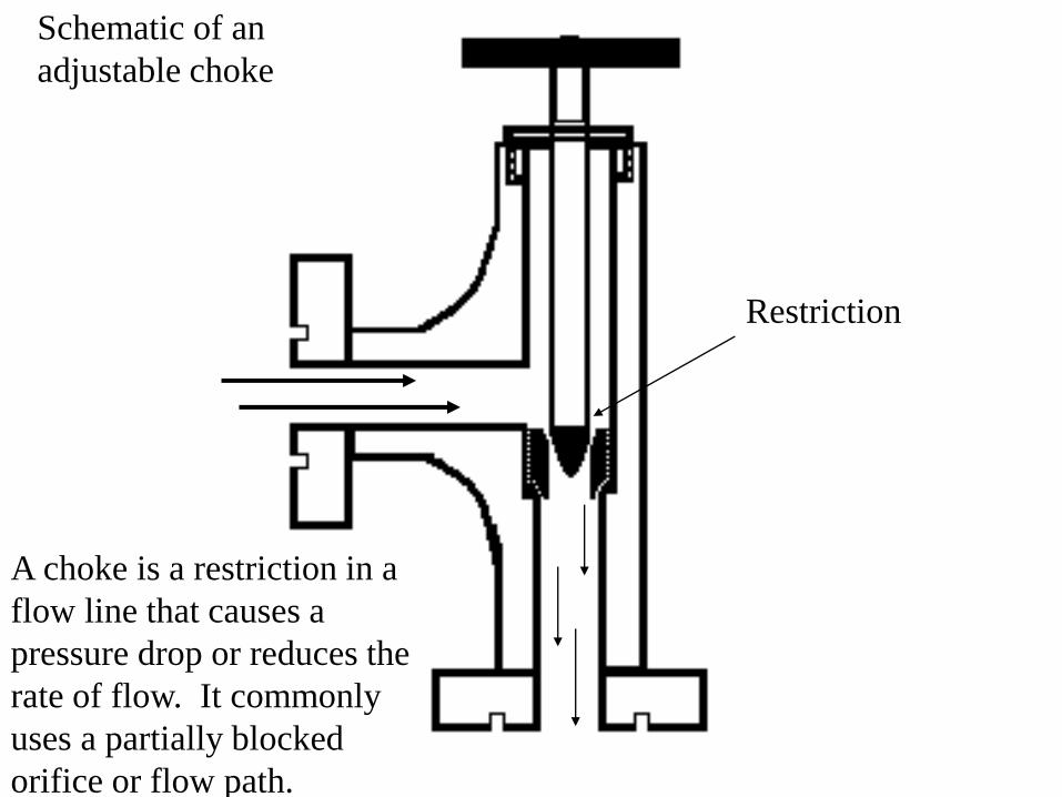
Restriction
Schematic of an
adjustable choke
A choke is a restriction in a
flow line that causes a
pressure drop or reduces the
rate of flow. It commonly
uses a partially blocked
orifice or flow path.

Variable Chokes - good
for bringing wells on
gradually and
optimizing natural gas
lift flow in some cases.
Prone to washouts from
high velocity, particles,
droplets.
Solutions - hardened
chokes (carbide
components), chokes in
series, dual chokes on
the well head.

Beans are fixed (non adjustable) orifices – ID size is in 64ths of an inch.
ID
Choke Uses
• Control Flow – achieve liquid lift
• Maximize use – best use of gas (lift?)
• Protect equipment – abrasion and erosion
• Cleanup – best use of backflow energy
• Control circulation – holds a back pressure
• Control pressures at surface (during flow)
• Control injection – on injection line

Pressure Drop
• Action
– Increased velocity (from gas expansion)
– Vaporization (flashing) of light ends to gas
– Vaporization of water
– Cavitation
– Cooling of gas
– Some heating of liquids
• Detriments
– Flashing – hydrocarbon light ends lost (value lost)
– Cavitation – erosion of surfaces in and around choke
– Erosion– solids, droplets and bubbles in high velocity flow
– Freezing – expansion of gasses cools the area – refrigeration principle

Pressure around the choke
Inlet or well
pressure, P1
Pressure drop through
the orifice
Pressure “recovery” , P2

Problems
• The larger the difference between the inlet
and outlet pressures, the higher the potential
for damage to the internals of the choke.
• When DP ratio (= DP/P1) rises above 0.6,
damage is likely. Look at choke type,
materials of construction, and deployment
methods (multiple chokes needed in series?)

Cavitation During Liquid Flow
Ultra low pressure region in and
immediately below choke causes bubble
to form from vaporizing liquid, Recovery
of pressure causes bubble to collapse; i.e.,
cavitation
The rapid collapse of the bubbles
causes high velocity movement of
liquid and damage around the site.
Pressure recovery line – limit of damage
Imploding
bubbles
and shock
waves

Distance Flow Traveled
Delta P
Recovery
P1
P2
P
r
e
s
s
u
r
e
VENA Contracta Phenomenon
The consequences of the low pressure region in the choke can lead to
severe problems with cavitation and related flashing (vaporization).

Flashing During Liquid Flow
Vaporization of light ends, but no
significant damage in this region since
pressure recovery not above vapor
pressure, hence bubbles don’t collapse.
Pressure recovery occurs downstream,
damage location from high velocity?

Freezing
• Expansion of gas (and solutions containing gas)
cools the surroundings. Excessive temp losses and
presence of water vapor can form an ice plug and
block flow.
Press
Distance Traveled
Recovery Recovery
Freezing Pt Temperature
dP
P1 T1
T2 P2
Temperature drop
across a choke is
about 1oF for
each atmosphere
of pressure drop.
Throttling Methods
• Needle and seat
• Multiple orifice
• Fixed Bean
• Plug and Cage
• External Sleeve
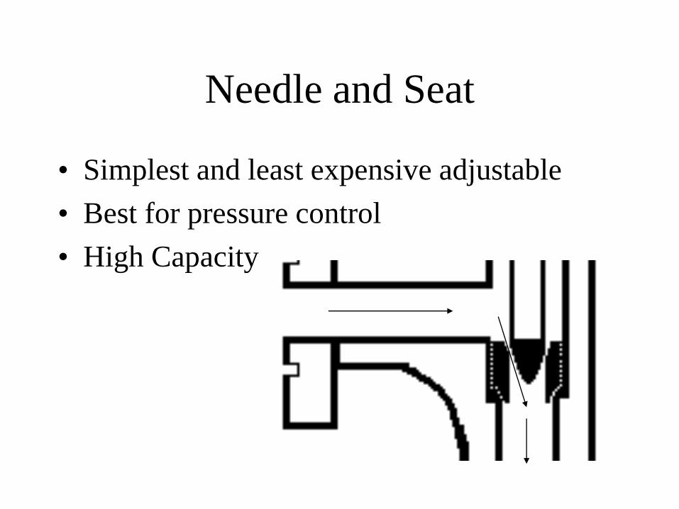
Needle and Seat
• Simplest and least expensive adjustable
• Best for pressure control
• High Capacity
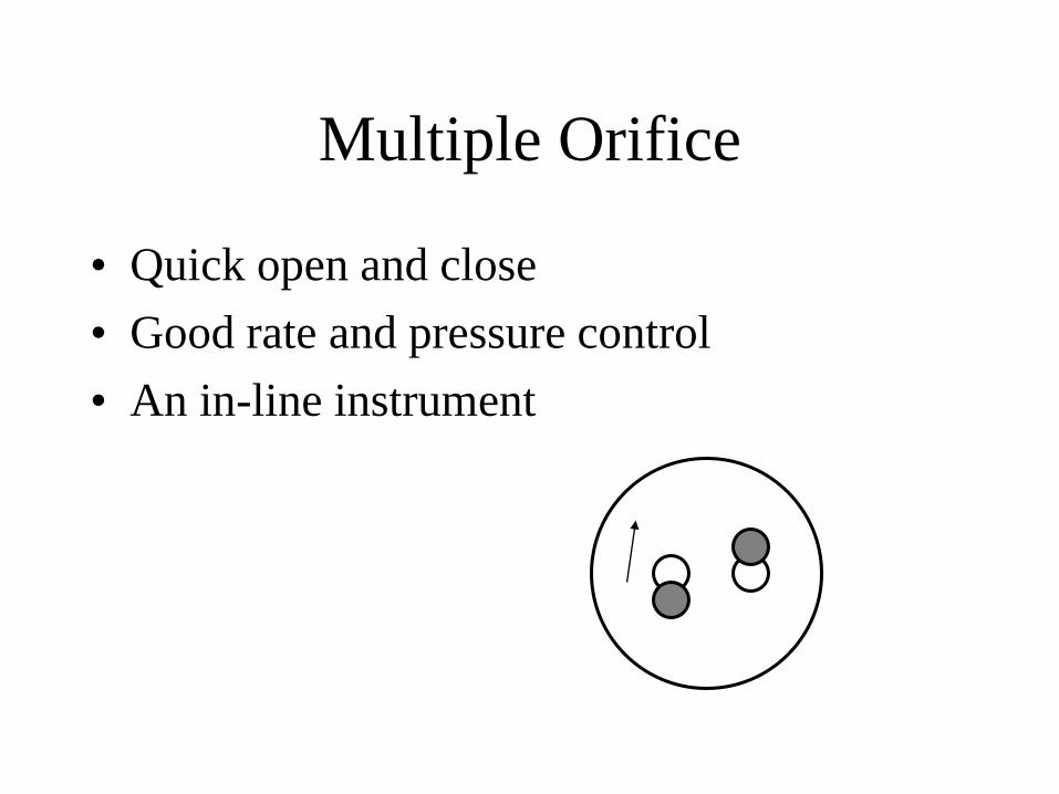
Multiple Orifice
• Quick open and close
• Good rate and pressure control
• An in-line instrument

Fixed Bean
• Best when infrequent change needed
• Used mostly on trees

Plug and Cage
• High capacity
• Good control
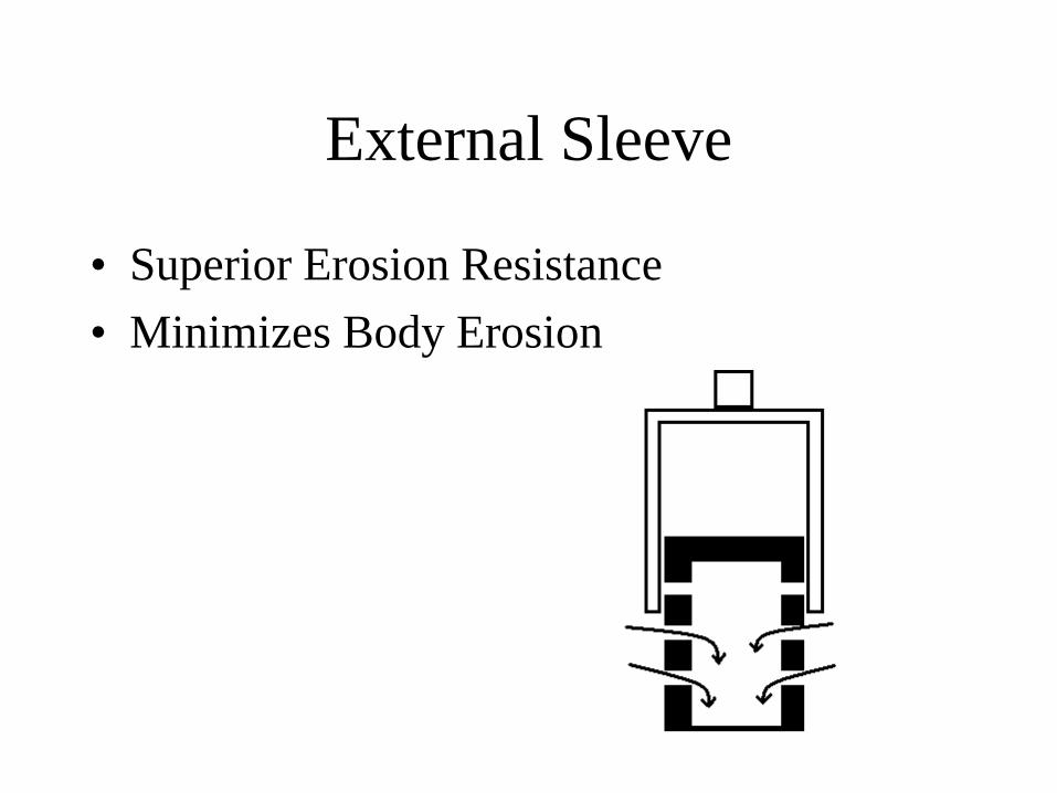
External Sleeve
• Superior Erosion Resistance
• Minimizes Body Erosion

Choke Sizing
• Control the flow – maximize production
• Minimized vibration damage
• Minimize erosion damage
• Choke Selection – based on application and
sizing.

Choke Selection (continued)
• Fluid – liquid, gas, or GOR of mix.
• Pressure – both pressure drop and total pressure
• Temperature – range of acceptable temperatures during service
• Solids in flow
• Droplets, bubbles
• Scale and organic deposit potential

Choke Sizing
• Cv = coefficient value
– Number of gallons of water per minute that will
pass through a restriction with a pressure drop
of 1 psi at 60oF.
– Used as the “flow capacity index”
– Does not correspond to a specific throttling
method.
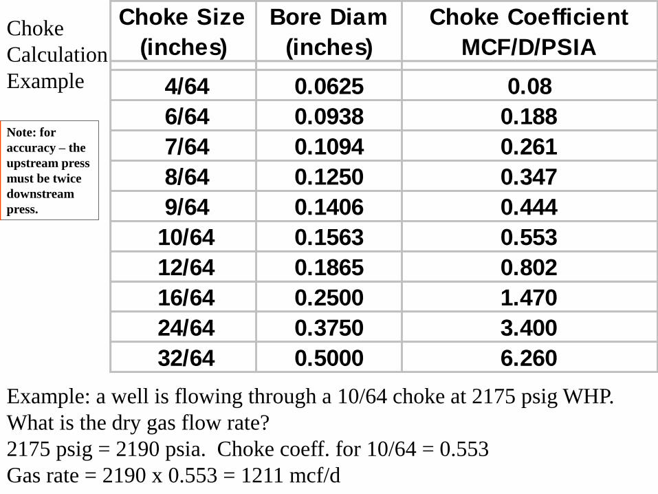
Choke Size
(inches)
Bore Diam
(inches)
Choke Coefficient
MCF/D/PSIA
4/64 0.0625 0.08
6/64 0.0938 0.188
7/64 0.1094 0.261
8/64 0.1250 0.347
9/64 0.1406 0.444
10/64 0.1563 0.553
12/64 0.1865 0.802
16/64 0.2500 1.470
24/64 0.3750 3.400
32/64 0.5000 6.260
Example: a well is flowing through a 10/64 choke at 2175 psig WHP.
What is the dry gas flow rate?
2175 psig = 2190 psia. Choke coeff. for 10/64 = 0.553
Gas rate = 2190 x 0.553 = 1211 mcf/d
Choke
Calculation
Example
Note: for
accuracy – the
upstream press
must be twice
downstream
press.

Flow rate estimation by the pressure
and choke size for dry gas.
Qest. = 24 * (P1+15) * Choke size2/1000
For a tubing pressure of 4000 psi and a 24/64”
choke, the gas flow estimate is:
Qest. = (24 * (4000+15) * (0.375)2 ) / 1000
Qest. = 13 to 14 mmscf/d

Erosion - damage caused by impingement of particles, droplets,
bubbles and even liquid on any solid surface at high velocity.
To reduce erosion, slow down the velocity.
A choke is required for throttling, never
use a gate valve. If wells must be brought
on line without a choke, use the outer wing
valve if rated for the job.
Partly open valve – an erosion area
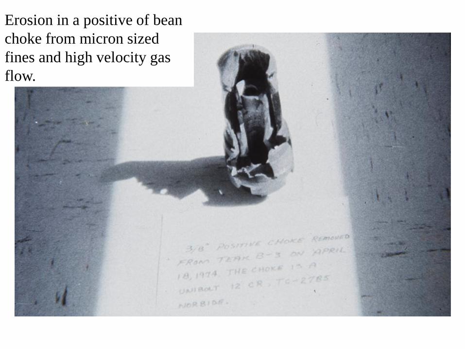
Erosion in a positive of bean
choke from micron sized
fines and high velocity gas
flow.

Typical flow patterns (and
erosion) in a bean choke.

Erosion at the exit
flange
JPT, March 1998

The velocity profile and pressure drop across a choke with a large
pressure drop – opportunity for erosion is very high.
JPT, March 1998

One solution to the problem is to take the pressure drop in series and
hold a slight backpressure. For example, a 1000 to 0 psi pressure drop
produces a 68 fold expansion in gas volume, while a 1500 to 500 psi
pressure drop produces a 3 fold gas volume expansion.
JPT, March 1998
Quiz – Choke Sizing
• A dry gas well flows at 12 mmscf/d with a
well head pressure of 2200 psi. Select a
choke size and a down stream pressure that
will allow flow but not create damage
through the choke.