Embed Size (px)
Citation preview
MR-02-O62-EN
4881 Murietta Street.Chino, CA. 91710
cpc reserves the right to revise any information(technical details) any time without notice, for printing mistakes or any other incidental mistakes. We take no responsibility.
2017.06.15 Printed in Taiwan

Product Introduction
Ordering Information
AR/HR Series Lubrication Storage Testing Report
Dimensions and Specifications
5.12 Wide MRU-W series - Tapped from bottom5.11 Standard MRU-M series - Tapped from bottom
5.1 Standard MR-M SU/ZU series5.2 Standard MR-M SS/ZZ series5.3 Standard MR-M SUE/ZUE series5.4 Standard MR-M EE/EZ series5.5 Standard MR-M EU/UZ series5.6 Standard MR-W SU/ZU series5.7 Standard MR-W SS/ZZ series5.8 Standard MR-W SUE/ZUE series5.9 Standard MR-W EE/EZ series5.10 Standard MR-W EU/UZ series
20
Product Introduction 44
46
Ordering Information 47
Dimensions and Specifications 48
50
222426283032343638
4040
6. Carbon Steel 41
Company Profile
Chieftek Precision Co., Ltd. (cpc), revolves around a core team of professional managers, engineers and highly skilled technicians. Together, the company devotes its efforts toward R&D, the manufacturing of high quality linear motion components and long-term sustainability. cpc attained its initial success by focusing on the miniature linear motion field with its highly acclaimed MR series linear guides. These found major use in precision measurement and inspection, semiconductor and other related electronic industries. As business grew, so did the company’s product line. Today, cpc’s linear guides range from our vaulted MR serried, the general purpose ARC series for automation machine tools, HRC and ERC series for heavy load machine tools, to the RR series with roller bearings for applications requiring high rigidity and precision under extra heavy loads. cpc’s linear guides are compatible with industry standard sizes while providing superior rigidity and precision.
Not satisfied at being just a mechanical component provider, cpc began an intensive R&D effort into the field of linear motors. The result is the P series ironless linear motors, with the highest thrust density and efficiency of its kind, quickly followed by the C series iron-core linear motor the most compact linear motor in the industry and delivering consistently reliable high thrust with low cogging force.
To lower the technical barrier for customers more familiar with tradition belt or ball screw driven systems, cpc packaged its linear motors into the CLS/CLMS series of compact linear stages while customizing its linear motor stages, tables and subsystems. Such products integrate the linear motor, linear guide and positioning systems into a compact, ready to use package the more traditional customers without having to concern themselves with the details of mechanical, electrical and electronics integration.
As linear motors cannot operate without a control system, the next logical step for cpc was to develop the TC1 series servo drive. The TC1 series features high power density, easy to use auto-tuning and an advanced feature set to aid machine builders to create their next breakthrough product. Spanning the field of mechanics, electrics and electronics, the release of TC1 sets another milestone for cpc on its path towards becoming a total mechatronics solution provider for linear motion control.
Time line of major developments1998 Established
2000 Official production of the MR size 5~15 Miniature Guide Series
2004 Extension into size 3 and 2 miniature linear guide production
2005 Establishment of factory operations in the Tainan Science Park
2007 Production of the ARC/HRC Series Ball Type Standard Size Linear Guides which have achieved ISO 9001:2000 certification
2008 Established cpc USA ( Chieftek precision USA) Establishment of cpc Kunshan, China (Chieftek machinery kunshan co., ltd.) Production of the full range Ironless linear Motor P series
2010 Establishment of cpc Europa GmbH Achievement of ISO 9001:2008 certification
2011 New factory expansion
2013 Wide ball type linear guide production
2014 Achievement of ISO 14001:2000 certification Achievement of OHSAS 18001:2007 certification Achievement of CNS 15506:2011 certification Production of full range Ironcore Linear Motor C Series Mass production of CLS compact linear Motor Stage Series Standard 4-Row Roller-type ARR/HRR/LRR Linear Guide Series announced
2015 Mass production of the TC1 AC Linear Motor Servo Driver Mass production of the CLMS Core Type Linear Motor Stage

Designed for high load, high moment applications
Lubrication storageOur Environmentally-friendly system requires less lubricant.
MR Miniature linear guide series have three accuracy grades for design selections: Precision (P), High (H), Normal (N).
Our steel reinforcement plate ensures sturdy assembly and a longer product lifespan
Unique ball re-circulation design
Built-in bottom seal
MaterialAll of our MR miniature linear guide series are made from heat treated stainless steel material.
Embedded inverse hook design
Precision
* We recommend this new design as a priority purchase.
02 03

04 05
Dustproof design
SS series-end sealThe standard end seal design can be hermetically sealed and dustproofed. This extends the productlifespan, reduces lubrication grease consumption, and ensuresa long-lasting lubrication effect. The special seal slip design also ensures a low friction force so as not to affect the product's running smoothness.
Environmentally friendly lubrication designZZ series-end seal and lubrication padThe two ends of the runner block feature a hermeticlubrication grease injection design. This is capableof bringing the lubrication grease to the raceway via continuous steel ball circulation, thereby achieving an effective long-term lubrication effect. A built-in lubrication pad can also be utilized toward prolonging lubrication further for long-term motion, reducing maintenance costs while demonstrating a superior lubrication capability during short stroke motion.
Lubrication pad Z series
End seal S series
Brand new U series Features: the built-in bottom seal does not affect the friction resistance if aclearance is smaller than 0.1mm.
SU series - end, bottom seals
In addition to a normally equipped end seal, our newly designed runner block is equipped with an extra bottom seal. This prevents foreign matter from entering via the lower side of the runner block into the running rail, thereby extending the working life of the runner block
* the new design is recommended for priority purchase.* the new design is recommended for purchase in priority.
* the new design is recommended for priority purchase.
ZU series - end, bottom seals and lubrication pad
A newly designed bottom seal can prevent lubrication grease from spilling below the runner block. In addition,a built-in mounted lubrication pad further strengthens the series' grease-saving effects while extending its re-greasing interval.
End seal
Bottom seal SU/ZU series
End reinforcing design
EE series-end seal and reinforcement plateThis series utilizes two stainless steel reinforcement plates to cover the two plastic ends of the slide block completely and stainless steel screws to secure the upper and lower sides of the runner steel block, thereby strengthening the rigidity and increasing the coverage area of the end cap. This ensures faster running speeds while a gap sealing design between the reinforcement plate and slide rail enables an added wiping function
Running speed Vmax=5m/s,amax=300m/s2
(60m/s2 can be reached without prepressing)
EZ series - end seal, reinforcing plate and lubrication padThe built-in lubrication pads at the two ends of the runner block conform to environmental protection requirements and reduce maintenance costs.
EU series - end seal, stainless steel bottom seal and reinforcement plateThe stainless steel bottom seal protects the runner block from unnecessary damage caused by collision with foreign objects. Due to this runner block series having our strongest protective capability, its use is recommended for environments with many iron scraps around.
UZ series - end seal, stainless steel bottom seal, reinforcement plate and lubrication padThe lubrication pad can provide highly rigid runner blocks with better lubrication and grease storage capabilities, and reduce re-greasing time.
Stainless steel reinforcement plate E series
Stainless steel bottom seal U series(The gap is less than 0.1mm)
Brand new UE series
SUE series - end seal, bottom seal and reinforcement plate
our new design includes an in-built bottom seal. This strengthens the runner block's bottom dustproofing capability while its stainless steel reinforcement plate prevents hard and rigid objects from striking at the plastic cap from the end position. This is why its dustproofing effect is the strongest among all of our product series.
* the new design is recommended for priority purchase.
ZUE series - end seal, bottom seal, reinforcing plate andlubrication pad
The newly designed bottom seal protects lubrication grease from spilling below the runner block. with our built-in lubrication pad, an additional grease saving effect is attained, further prolonging prolonging our product's re-lubrication timeframe.
Reinforcement plate
Bottom seal

06 07
Accuracy Precision High Normal
High load and high moment capacity
Dust Proof DesignOur standard design comes equipped with an end seal that effectively restricts dust contamination and prolongs lubrication, ensuring longer product life. Our specially-designed low friction seal slips do not affect running smoothness.
The MR Miniature Linear Guide Series is designed using tworows of recirculating balls. The design uses a Gothic profile with a 45º contact angle to achieve an equal load capacityin all directions. Within the restriction of limited space, larger stainless steel balls are used to enhance load and torsion resistance capacity.
Under equal widthed rails, the black line indicatedcpc linear guides provide greater surface contact ascompared to competing products (indicated with thered-dotted line).
Embedded inverse hook design forreinforced mechanical integrationWhen the runner block is in motion and changing direction, the circulating stainless steel balls inside the raceway generate impact force against the plastic end cap. As the demand for rapid motion in the automation industry has increased, cpc has invented inverse plastic hooks to tightly secure our miniature blocks by effectively distributing the applied stress over a larger area.
Brand new designSuitable for :High speed belt driven mechanisms High speed carrier designs Automation linkage between stations
MR-SS/ZZ,SU/ZU type is:
MR-EE/EZ,EU/UZ,SUE/ZUE type is:
1. Product Introduction 2. Technical Information
2.1 Precision
AccuracyMR miniature linear guide serieshave three accuracy grades (P,H,N)for your choice.
Table of accuracy
Admissible height Hdimension Tolerance
Height variation fordifferent runner blockson the same railposition
Admissible width Wdimension tolerance
Width variation fordifferent runnerblocks on the samerail position
The maximum speed for the standard
Maximum acceleration
The maximum speed for the standard
Maximum acceleration(If preload is at V0, capable of reaching 60m/s2)
(If preload is at V0, capability of reaching 40m/s2)
Linear block relative to linear rail, datum plane parallel motion precision
Rail length (mm)

08 09
When grease lubrication is applied, we recommend synthetic oil-based lithium soap grease with a viscosity between ISO VG32-100.
For oil lubrication, we recommend syntheticoils CLP, CGLP (based on DIN 51517) or HLP(based on DIN 51524) with a viscosity range ofbetween ISO VG32-100 and a work ingtemperature range between 0°C~+70°C. (Werecommend ISO VG10 for use in lowertemperature environments.)
The MR Miniature Linear Guide series has three degrees of preload capacity: V0, VS and V1 (as described in the preload table below.)Appropriate preload levels can enhance the stiffness, precision, and torsion resistance performance of the linear guide. But an inappropriate application thereof can also negatively affect the product life and itsmotional resistance levels.
Preload
The MR Miniature Linear Guide can operate in arange of temperatures from -40ºC~ + 80ºC.For short term operation, it can reach up to +100ºC.
The linear guide must be lubricated for protection before first time use. Contaminantsof any kind, weather liquid or solid, should be avoided.
ZZ/ZU/EZ/UZ/ZUE Lubrication Storage block
Please contact our technical department for lubrication assistance if the runner blockis intended for use in a wall mount configuration.
The runner block should be moved back and forth during lubrication.
The lubricant can be added either manually or automatically directly onto the rail raceway.
A thin layer of observable lubricant should be maintained on the surface of the rail .
Please notify us if product is intended for use in acidic, alkaline, or clean room applications.
The re-lubrication interval must be shortened if the travel stroke is < 2 or > 15 times thelength of the steel body of the runner block.
Operating Temperature
1. The block already contains lubricants which can be directly installed on the machine, without the need for additional washing.2. When first washing the blocks, please do not soak them in the lubricant before both the detergent and cleaning naphtha within are totally dry. The block is ready for installation only after the lubrication storage is full of the lubricant.
2. Technical Information
2.2 Preload 2.3 Lubrication
FunctionWhen operating the linear guide under sufficient lubrication conditions, a one-micron layer of oil forms at the contact zone, separating the loaded rolling components and the raceway. Sufficient lubrication will:
Reduce friction
Reduce wear
Reduce corrosion
Dissipate heat and increase service life
The lubricant can be injected into the lubrication holes on either end of the runner block.
Re-lubrication must be completed before contamination or discoloration of the lubricant occurs.
Smooth and high precision
High rigidityMinimizes vibrationHigh precisionLoad balance

10 11
00 For general applications
01 For low-friction, low-noise applications
02 For clean room applications
03 For clean room and vacuum environment applications
04 For high-speed applications
05 For micro-oscillation applications
11 For general applications, ISO V32-68
2.3 Lubrication - continued
Re-lubrication shall be applied before the lubricant in the block is contaminated or changes color.
The amount of the lubricant applied should be 1/2 of the first lubrication. When applying lubricant, this should be done until it seeps out from the device.
Re-lubrication shall be applied under steady operating temperature, with the runner block moved back and forth throughout for optimum distribution.
The re-lubrication interval depends on individual use, as the speed, load, stroke length and operating environment are all factors. Careful observation of rails and blocks is the basis to determine the optimal re-lubrication interval; as a rule of thumb, re-lubricate at least once per year. Do not apply water-based coolant liquid on the linear rails or slide. Inject lubricant through injection holes on both ends of the runner block with the recommended cpc brand injector.
If the stroke is smaller than twice or greater than 15 times the steel body length of the block, there-lubrication interval shall be shortened.
3 MN
3 M L
5 MN5 M L
7 MN
7 M L
9 MN
9 M L
12 MN
12 ML
15 MN
15 ML
5 WN
3 WN
5 W L
3 W L
2 W L
7 WN
7 W L
9 WN
9 W L
12 WN
12 WL
15 WN
15 WL
- -
2. Technical Information
Re-lubrication Lubrication grease
Lubrication oil
Re-lubrication Interval
Modelcode
Modelcode
First lubrication(cm3)
First lubrication(cm3)

12 13
Friction
Friction Factors
Sealing DesignThe MR Miniature Linear Guide Series haslow-friction characteristics with a stableand minor starting friction.
The MR Miniature Linear Guide Series areenclosed by end seals on both ends ofthe runner block. Optional side seals can also create an all-around sealing system.
Number of balls in the gothic arch load zone.
Resistance from lubricant to ball pressure.
Resistance caused by contaminants.
Note: Under maximum stress levels, a permanent deformation will be generated at the contact point. This corresponds roughly to about 0.0001 times the rolling element diameter.(The above is according to ISO 14728-2)
Static load safety factor calculation
The permissible static and applied static loadof the MR Miniature Linear Guide Series islimited by:
The equivalent static load and static torque are the largest load and torque, please consult with formulas (13) and (14).
In order for the linear bearing to permanentlywithstand potential deformation while delivering a guaranteed accuracy and reliable motion, the static load safety factor, So should be calculated with formulas (11) and (12).
basic static load in acting direction N
Friction of end seal under lubrication
Friction of end seal(Nmax)(under lubrication)
2. Technical Information2.4 Friction
Sealing system.
Collision between the balls during operation.
Collision between the balls and the return path.
The MR Miniature Linear Guide Series
Static load P0 and moment M0 Static load safety factor S0
The static load of the linear guide.
The permissible load of fixed screws.
The permissible load for the connected partsof the mechanism.
The static load safety factor required for theapplication.
static load safety factor
equivalent static load in acting direction N
basic static moment in acting direction Nm
equivalent static moment in acting direction Nm
Operation condition
Normal operation
Load with vibration or impact
High accuracy and smooth running
2.5 Load Capacity and Rating Life
Static Load Rating C0
Measuring the static load of the travel force along the acting direction, the maximum stress between the rolling balls and raceway is as follows:
14 15
If there are changes in both load and speed, theequivalent dynamic load can be calculated accordingto formula (8).
If there is a change in speed only, the equivalent speed can be calculated according to formula (7).
rating life in hours
dynamic load rating
equivalent load
length of stroke
stroke repetition
average speed
Single Block Bearing the MomentFor a given structure, if the block needs to bear torque moments from Mp and My directions, the maximummoment that the block can withstand while still maintain smooth running conditions measures at about 0.3-0.1times the static moment rating. The higher the preload, the higher the loading value and vice versa.
In the case of any design questions, please contact the cpc technical department.
Combined Equivalent Dynamic LoadIf the linear guide bears the load from arbitrary angelsso that the acting force does not conform to horizontal and vertical directions, its equivalent dynamic load is calculated as shown on formula (9).
Under the condition with the momentIf the linear guide bears the load and the momentsimultaneously, its equivalent dynamic load is calculatedwith formula (10).According to ISO 14728-1, when equivalent dynamic loadtolerance rates below ≦ 0.5C, P ≦ C0m, a realiableproduct life value can be calculated.
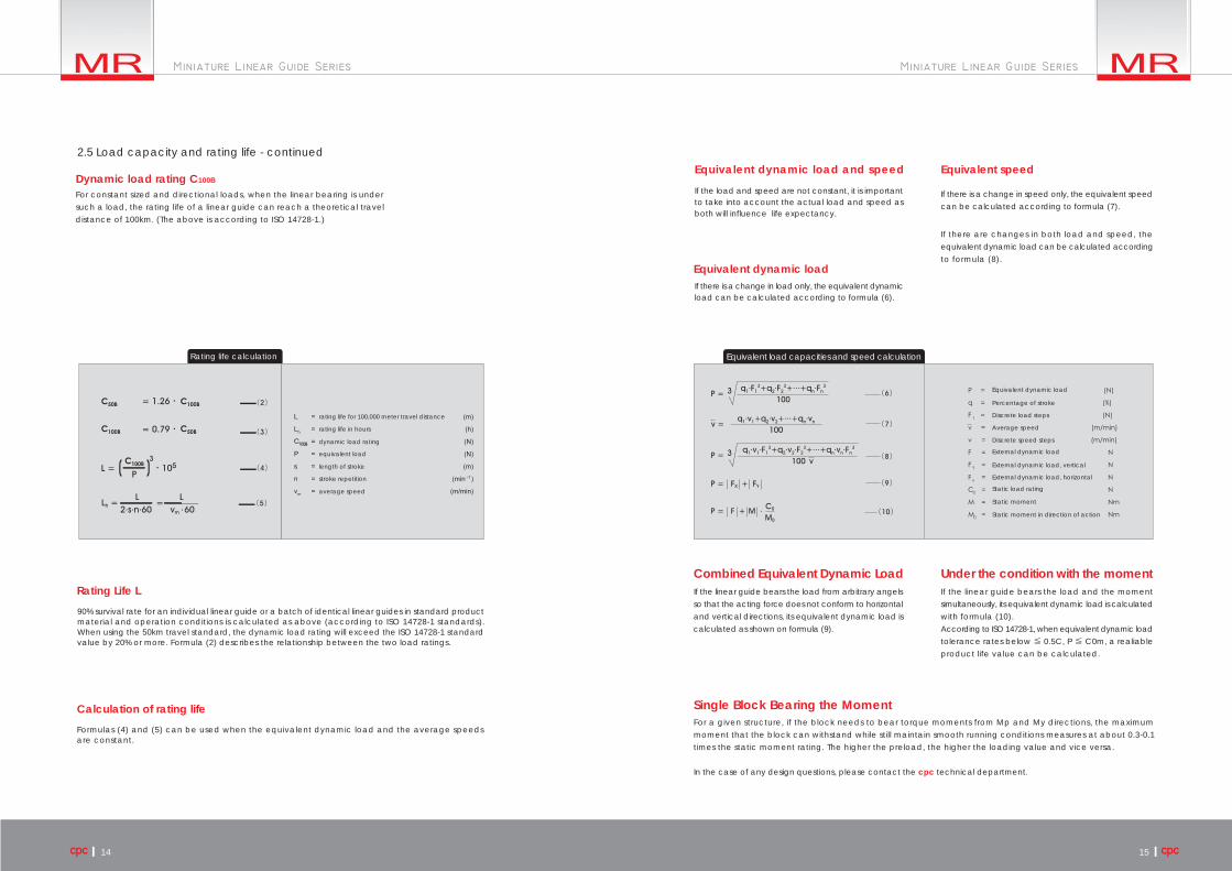
2.5 Load capacity and rating life - continued
Dynamic load rating C100BEquivalent dynamic load and speed
Equivalent dynamic load
Equivalent speed
Rating Life L
Calculation of rating life
For constant sized and directional loads, when the linear bearing is undersuch a load, the rating life of a linear guide can reach a theoretical traveldistance of 100km. (The above is according to ISO 14728-1.)
Rating life calculation
rating life for 100,000 meter travel distance
Formulas (4) and (5) can be used when the equivalent dynamic load and the average speedsare constant.
If the load and speed are not constant, it is important to take into account the actual load and speed as both will influence life expectancy.
If there is a change in load only, the equivalent dynamic load can be calculated according to formula (6).
Equivalent load capacities and speed calculation
Equivalent dynamic load
Percentage of stroke
Discrete load steps
Average speed
Discrete speed steps
External dynamic load
External dynamic load, vertical
External dynamic load, horizontal
Static load rating
Static moment
Static moment in direction of action
90% survival rate for an individual linear guide or a batch of identical linear guides in standard product material and operation conditions is calculated as above (according to ISO 14728-1 standards). When using the 50km travel standard, the dynamic load rating will exceed the ISO 14728-1 standard value by 20% or more. Formula (2) describes the relationship between the two load ratings.

16 17
Butt-jointing is required when lengths exceed Lmax.(For more detailed information, pleasecontact cpc for technical support.)
Standard length of one rail
Standard length of one rail
For special process requirements, please contact technicalsupport.
special process for rail
customer designated lubricant
no lubricant
According to application environment.
For special process requirements, please contact technical support.
The straightness of the linear guide rail is specially calibrated byprecision fine grinding.
Please contact technical support.
MR U M N K 2 P J-15 -15 IIEE V1 -310L15
Rail material: No Mark : standard rail K : carbon steel (Now available: size 9, 12, and 15. )
SS: with end sealZZ: end seal + lubrication storageSU: end seal + bottom sealZU: end seal + bottom seal + lubrication storageEE: end seal + reinforcement plateEZ: end seal + reinforcement plate + lubrication storageEU: end seal + reinforcement plate + stainless bottom sealUZ: end seal + reinforcement plate + stainless bottom seal + lubrication storageSUE: end seal + bottom seal + reinforcement plateZUE: end seal + bottom seal + reinforcement plate + lubrication storage
Accuracy Grades: P (Precision), H (High), N (Normal)
Preload classes: V0: clearance VS: standard V1: light preload
Block quantity: Quantity of the runner block
Customization code
End hole pitch (mm)
Starting hole pitch(mm)
Number of rails on the same moving axis
MS : Metal Stopper on stainless steel Rail
1. To prevent the block from separating from the rail during transportation or installation; this may cause item damage or scattering.
2. Perfect for rails installed on the vertical axis (Z-axis) to prevent gravity induced block separation from the rail.
3. The stoppers and screws are made of stainless steel material with an anti-corrosion function.
4. Strongly recommended NOT to use as a mechanical travel limiter or breaking system.
MS : Metal Stopper on Stainless Steel Rail
Unit: mm
Unit: mm Unit: mm
PitchL2, L3min.L2, L3max.L0 max.
PitchL2, L3min.L2, L3max.L0 max.
When the required length of rail exceeds the standard raillength, a butt-joint can be specified. The rail butt-jointindication is marked as illustrated below.
Applies to MR9M, MR12M, MR15M, MR7W & MR9W rails.
Applies to MR12W, MR15W rails.
Suitable for clean room environments.
low dust generation
Ws
Hs
Ts
M R - 7 MM R - 9 MMR-12MMR-15MM R - 7 WM R - 9 WMR-12WMR-15W
1013171918232947
56776677
89
1214
9111314
Ws max Ts Hs max
Dimension
Rail Size
3. Ordering Information
3.1 Length of Rail
Length of Rail
Rail length (mm)
Product Type: MR: Miniature Linear Guide
Special Rail U: upward screwing rail No Mark: standard rail
Rail dimension: The width of rail ex. : 2,3,5,7,9,12,15
Rail type: M: standard W: wide
Wide type
Block type: L: long N: standard
Standard type
Customization RequirementThe meaning of suffix characters:
slide rail connection
slide rail connection
special process for railspecial processing for blockspecial straightness requirements for rail
Cap M3Cap M4customer designated lubricant
with Inspection report
special processing for block
with Inspection report
special straightness requirements for rail

Height and chamfer of reference edgeTo avoid interference, the corner of the referenceedge should have a chamfer. If not, please refer to thefollowing table for the height of the reference edgecorner and the height of the reference edge.
The mounting surface should be groundor fine milled to reach a surface roughness
Screw tightening torque (Nm)
Inaccurate mounting surfaces will affect the operationalaccuracy of the linear guide when the mounting surface height differential is greater than the values calculated by formulas (15), (16), and (17). The rating lifetime will also be shortened.
Rail: Both sides of the track rail can serve as thereference edge without any special marking.Block: Reference edge is opposite to the groove markingside.
18 19
Height and chamfer of the reference surface
h2Eh1
5M 1.2 1.51.9
7M 1.2 1.52.8
3M 0.81.5 1
9M 1.8 2.23
12M 2.64 3
15M 4.5 3.6 4
0.90.6
0.9 1.2
0.8 1.1
3.12.7
1.71.3
2.52.1
h1 E
0.8
-
-
-
- -
-
-
-
-
- - -
- -
1.1
3.22.8
1.71.3
2.31.9
h1 E
1.41
1.6 2
2.92.5
Eh1
0.7 1.0
2.92.4
2.11.7
1.51.1
h1 E
SS/ZZ SU/ZU EE/EZ EU/UZ SUE/ZUE
h2Eh1
5W
7W
3W
2WL
9W
12W
15W
h1 E h1 E Eh1 h1 E
SS/ZZ SU/ZU EE/EZ EU/UZ SUE/ZUE
2
2.8
1.7
1.5
3
4
4.5
r1max
0.2
0.2
0.1
0.2
0.3
0.3
r1max
0.2
0.2
0.1
0.1
0.2
0.3
0.3
1.2
1.7
0.7
0.8
3
3.5
3.6
r2max
0.3
0.3
0.3
0.3
0.5
0.5
r2max
0.3
0.3
0.3
0.3
0.3
0.5
0.5
1.5
2
1
1
3.4
3.9
4
0.6
0.6
1
1.3
2.5
2.9
3
0.9
0.9
1.3
1.6
2.9
3.3
3.4
1.2
0.5
2.8
2.9
2.4
1.5
0.7
- -
-
-
-
-
-
-
-
-
-
-
-
-
-
-
3.2
3.3
2.8
2.4
2.1
2.4
2.8
2.5
2.8
0.60.4
1.1 1.4
2.82.4
2.82.4
2.62.2
Dimension
Dimension
ISO 3506-1
0.60.3
1.12.5
M1.6M2
0.15
M2.5/M2.6M3M4
1.81.2
1.30.8 0.6
2.5
M2
Steel Cast Iron
Cast IronNon Iron
Metal
M2.5/M2.60.6 0.4 0.3
124
M3M4
Screw grade 12.9Alloy Steel Screw A2-70 Stainless Screw
4. Insstallation Illustration
The mounting surface
Geometric and positional accuracy ofthe mounting surface
Reference edge
20 21
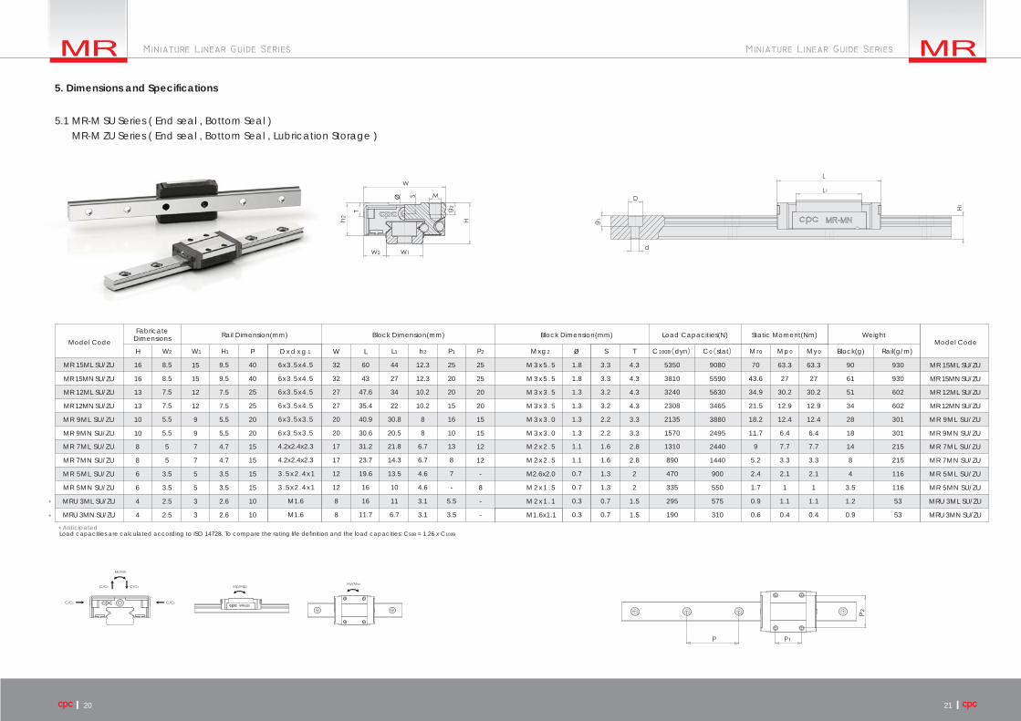
5.1 MR-M SU Series ( End seal , Bottom Seal )MR-M ZU Series ( End seal , Bottom Seal , Lubrication Storage )
Block(g) Rail(g/m)
MR 15ML SU/ZU
Model Code Model CodeFabricate
Dimensions Rail Dimension(mm) Block Dimension(mm) Block Dimension(mm) Load Capacities(N) Static Moment(Nm) Weight
16 8.5
8.5
7.5
7.5
5.5
5.5
9.5
9.5
40 6x3.5x4.5
6x3.5x4.5
6x3.5x4.5
6x3.5x4.5
6x3.5x3.5
6x3.5x3.5
4.2x2.4x2.3
4.2x2.4x2.3
3 .5x2 .4x1
3 .5x2 .4x1
M1.6
M1.6
40
25
25
32
32
60
43
47.6
35.4
40.9
30.6
31.2
23.7
11.7
19.6
16
16
44
27
34
22
30.8
20.5
21.8
14.3
6.7
13.5
10
11
12.3
12.3
10.2
10.2
8
8
6.7
6.7
3.1
4.6
4.6
3.1
27
27
20
20
17
17
12
12
8
8
25
20
20
15
16
10
13
8
7
-
5.5
3.5
25 M 3 x 5 . 5 1.8
1.8
1.3
1.3
1.3
1.3
1.1
1.1
0.7
0.7
0.3
0.3
3.3
3.3
3.2
3.2
2.2
2.2
1.6
1.6
1.3
1.3
0.7
0.7
4.3 5350
3810
3240
2308
2135
1570
1310
890
470
335
295
190
9080 70
43.6
34.9
21.5
18.2
11.7
9
5.2
2.4
1.7
0.9
0.6
63.3
27
30.2
12.9
12.4
6.4
7.7
3.3
2.1
1
1.1
0.4
63.3
27
30.2
12.9
12.4
6.4
7.7
3.3
2.1
1
1.1
0.4
90
61
51
34
28
18
14
8
4
3.5
1.2
0.9
930
930
602
602
301
301
215
215
116
116
53
53
5590
5630
3465
3880
2495
2440
1440
900
550
575
310
4.3
4.3
4.3
3.3
3.3
2.8
2.8
2
2
1.5
1.5
M 3 x 5 . 5
M 3 x 3 . 5
M 3 x 3 . 5
M 3 x 3 . 0
M 3 x 3 . 0
M 2 x 2 . 5
M 2 x 2 . 5
M2.6x2.0
M 2 x 1 . 5
M 2 x 1 . 1
M1.6x1.1
25
20
20
15
15
12
12
-
8
-
-
20
20
15
15
15
15
10
10
7.5
7.5
5.5
5.5
4.7
4.7
3.5
3.5
2.6
2.6
3.5
3.5
2.5
2.5
5
5
16
13
13
15
15
12
12
10
10
8
8
9
9
7
7
5
5
3
3
6
6
4
4
MR 15MN SU/ZU
MR 12ML SU/ZU
MR 12MN SU/ZU
MR 9ML SU/ZU
MR 9MN SU/ZU
MR 7ML SU/ZU
MR 7MN SU/ZU
MR 5ML SU/ZU
MR 5MN SU/ZU
MRU 3ML SU/ZU
MRU 3MN SU/ZU
MR 15ML SU/ZU
MR 15MN SU/ZU
MR 12ML SU/ZU
MR 12MN SU/ZU
MR 9ML SU/ZU
MR 9MN SU/ZU
MR 7ML SU/ZU
MR 7MN SU/ZU
MR 5ML SU/ZU
MR 5MN SU/ZU
MRU 3ML SU/ZU
MRU 3MN SU/ZU
H P W LD x d x g 1W2 W1 H1 h2L1 P1 P2 Mxg2 S T C100B dyn C0 stat Mr0 Mp0 My0ø
*
*
* Anticipated
5. Dimensions and Specifications
Load capacities are calculated according to ISO 14728. To compare the rating life definition and the load capacities: C50B = 1.26 x C100B

22 23
MR 15ML SS/ZZ 16 8.5
8.5
7.5
7.5
5.5
5.5
9.5
9.5
40 6x3.5x4.5
6x3.5x4.5
6x3.5x4.5
6x3.5x4.5
6x3.5x3.5
6x3.5x3.5
4.2x2.4x2.3
4.2x2.4x2.3
3 .5x2 .4x1
3 .5x2 .4x1
M1.6
M1.6
40
25
25
32
32
60.1
43.1
47.6
35.4
41
30.8
31.5
24
11.7
19.6
16
16
44
27
34.1
22
30.8
20.5
21.8
14.3
6.8
13.5
10
11
27
27
20
20
17
17
12
12
8
8
12
12
10
10
7.8
7.8
6.5
6.5
4.5
4.5
3
3
25
20
20
15
16
10
13
8
7
-
5.5
3.5
25 M 3 x 5 . 5 1.9
1.9
1.4
1.4
1.3
1.3
1.2
1.2
0.7
0.7
0.3
0.3
3.3
3.3
3.2
3.2
2.2
2.2
1.6
1.6
1.3
1.3
0.7
0.7
4.3 5350
3810
3240
2308
2135
1570
1310
890
470
335
295
190
9080 70
43.6
34.9
21.5
18.2
11.7
9
5.2
2.4
1.7
0.9
0.6
63.3
27
30.2
12.9
12.4
6.4
7.7
3.3
2.1
1
1.1
0.4
63.3
27
30.2
12.9
12.4
6.4
7.7
3.3
2.1
1
1.1
0.4
90
61
51
34
28
18
14
8
4
3.5
1.2
0.9
930
930
602
602
301
301
215
215
116
116
53
53
5590
5630
3465
3880
2495
2440
1440
900
550
575
310
4.3
4.3
4.3
3.3
3.3
2.8
2.8
2
2
1.5
1.5
M 3 x 5 . 5
M 3 x 3 . 5
M 3 x 3 . 5
M 3 x 3 . 0
M 3 x 3 . 0
M 2 x 2 . 5
M 2 x 2 . 5
M2.6x2.0
M 2 x 1 . 5
M 2 x 1 . 1
M1.6x1.1
25
20
20
15
15
12
12
-
8
-
-
20
20
15
15
15
15
10
10
7.5
7.5
5.5
5.5
4.7
4.7
3.5
3.5
2.6
2.6
3.5
3.5
2.5
2.5
5
5
16
13
13
15
15
12
12
10
10
8
8
9
9
7
7
5
5
3
3
6
6
4
4
MR 15MN SS/ZZ
MR 12ML SS/ZZ
MR 12MN SS/ZZ
MR 9ML SS/ZZ
MR 9MN SS/ZZ
MR 7ML SS/ZZ
MR 7MN SS/ZZ
MR 5ML SS/ZZ
MR 5MN SS/ZZ
MRU 3ML SS
MRU 3MN SS
MR 15ML SS/ZZ
MR 15MN SS/ZZ
MR 12ML SS/ZZ
MR 12MN SS/ZZ
MR 9ML SS/ZZ
MR 9MN SS/ZZ
MR 7ML SS/ZZ
MR 7MN SS/ZZ
MR 5ML SS/ZZ
MR 5MN SS/ZZ
MRU 3ML SS
MRU 3MN SS
H P W LD x d x g 1W2 W1 H1 h2L1 P1 P2 Mxg2 S T C100B dyn C0 stat Mr0 Mp0 My0ø Block(g) Rail(g/m)Model Code Model Code
FabricateDimensions Rail Dimension(mm) Block Dimension(mm) Block Dimension(mm) Load Capacities(N) Static Moment(Nm) Weight
5.2 MR-M SS Series (End seal)MR-M ZZ Series ( End seal , Lubrication Storage)
5. Dimensions and Specifications
Load capacities are calculated according to ISO 14728. To compare the rating life definition and the load capacities: C50B = 1.26 x C100B

24 25
MR 15ML SUE/ZUE 16 8.5
8.5
7.5
7.5
5.5
5.5
9.5
9.5
40 6x3.5x4.5
6x3.5x4.5
6x3.5x4.5
6x3.5x4.5
6x3.5x3.5
6x3.5x3.5
3 .5x2 .4x1
3.5x2 .4x1
40
25
25
32
32
61.6
44.6
49
36.8
41.9
31.6
20.2
16.6
44
27
34
22
30.8
20.5
13.5
10
13.1
13.1
10.9
10.9
8.5
8.5
5.0
5.0
27
27
20
20
12
12
25
20
20
15
16
10
7
-
25 M 3 x 5 . 5 1.8
1.8
1.3
1.3
1.3
1.3
0.7
0.7
3.3
3.3
3.2
3.2
2.2
2.2
1.3
1.3
4.3 5350
3810
3240
2308
2135
1570
470
335
9080 70
43.6
34.9
21.5
18.2
11.7
2.4
1.7
63.3
27
30.2
12.9
12.4
6.4
2.1
1
63.3
27
30.2
12.9
12.4
6.4
2.1
1
90
61
51
34
28
18
4
3.5
930
930
602
602
301
301
116
116
5590
5630
3465
3880
2495
900
550
4.3
4.3
4.3
3.3
3.3
2
2
M 3 x 5 . 5
M 3 x 3 . 5
M 3 x 3 . 5
M 3 x 3 . 0
M 3 x 3 . 0
M2.6x2.0
M 2 x 1 . 5
25
20
20
15
15
-
8
20
20
15
15
7.5
7.5
5.5
5.5
3.5
3.5
3.5
3.5
16
13
13
15
15
12
12
10
10
6
6
9
9
5
5
MR 15MN SUE/ZUE
MR 12ML SUE/ZUE
MR 12MN SUE/ZUE
MR 9ML SUE/ZUE
MR 9MN SUE/ZUE
MR 5ML SUE/ZUE
MR 5MN SUE/ZUE
MR 15ML SUE/ZUE
MR 15MN SUE/ZUE
MR 12ML SUE/ZUE
MR 12MN SUE/ZUE
MR 9ML SUE/ZUE
MR 9MN SUE/ZUE
MR 5ML SUE/ZUE
MR 5MN SUE/ZUE
H P W LD x d x g 1W2 W1 H1 h2L1 P1 P2 Mxg2 S T C100B dyn C0 stat Mr0 Mp0 My0ø Block(g) Rail(g/m)Model Code Model Code
FabricateDimensions Rail Dimension(mm) Block Dimension(mm) Block Dimension(mm) Load Capacities(N) Static Moment(Nm) Weight
5.3 MR-M SUE Series ( End seal, Bottom Seal, Reinforcement Plate )MR-M ZUE Series ( End seal, Bottom Seal , Reinforcement Plate , Lubrication Storage )
Load capacities are calculated according to ISO 14728. To compare the rating life definition and the load capacities: C50B = 1.26 x C100B
5. Dimensions and Specifications

26 27
MR 15ML EE/EZ 16 8.5
8.5
7.5
7.5
5.5
5.5
9.5
9.5
40 6x3.5x4.5
6x3.5x4.5
6x3.5x4.5
6x3.5x4.5
6x3.5x3.5
6x3.5x3.5
3 .5x2 .4x1
3.5x2 .4x1
40
25
25
32
32
61.6
44.6
49
36.8
41.9
31.6
20.2
16.6
44
27
34
22
30.8
20.5
13.5
10
27
27
20
20
12
12
12.8
12.8
10.7
10.7
8.3
8.3
4.9
4.9
25
20
20
15
16
10
7
-
25 M 3 x 5 . 5 1.8
1.8
1.3
1.3
1.3
1.3
0.7
0.7
3.3
3.3
3.2
3.2
2.2
2.2
1.3
1.3
4.3 5350
3810
3240
2308
2135
1570
470
335
9080 70
43.6
34.9
21.5
18.2
11.7
2.4
1.7
63.3
27
30.2
12.9
12.4
6.4
2.1
1
63.3
27
30.2
12.9
12.4
6.4
2.1
1
90
61
51
34
28
18
4
3.5
930
930
602
602
301
301
116
116
5590
5630
3465
3880
2495
900
550
4.3
4.3
4.3
3.3
3.3
2
2
M 3 x 5 . 5
M 3 x 3 . 5
M 3 x 3 . 5
M 3 x 3 . 0
M 3 x 3 . 0
M2.6x2.0
M 2 x 1 . 5
25
20
20
15
15
-
8
20
20
15
15
7.5
7.5
5.5
5.5
3.5
3.5
3.5
3.5
16
13
13
15
15
12
12
10
10
6
6
9
9
5
5
MR 15MN EE/EZ
MR 12ML EE/EZ
MR 12MN EE/EZ
MR 9ML EE/EZ
MR 9MN EE/EZ
MR 5ML EE/EZ
MR 5MN EE/EZ
MR 15ML EE/EZ
MR 15MN EE/EZ
MR 12ML EE/EZ
MR 12MN EE/EZ
MR 9ML EE/EZ
MR 9MN EE/EZ
MR 5ML EE/EZ
MR 5MN EE/EZ
H P W LD x d x g 1W2 W1 H1 h2L1 P1 P2 Mxg2 S T C100B dyn C0 stat Mr0 Mp0 My0ø
*
Block(g) Rail(g/m)Model Code Model Code
FabricateDimensions Rail Dimension(mm) Block Dimension(mm) Block Dimension(mm) Load Capacities(N) Static Moment(Nm) Weight
* Anticipated
5.4 MR-M EE Series ( End seal, Reinforcement Plate )MR-M EZ Series ( End seal , Reinforcement Plate , Lubrication Storage )
5. Dimensions and Specifications
Load capacities are calculated according to ISO 14728. To compare the rating life definition and the load capacities: C50B = 1.26 x C100B

28 29
MR 15ML EU/UZ 16 8.5
8.5
7.5
7.5
5.5
5.5
9.5
9.5
40 6x3.5x4.5
6x3.5x4.5
6x3.5x4.5
6x3.5x4.5
6x3.5x3.5
6x3.5x3.5
40
25
25
32
32
61.6
44.6
49
36.8
41.9
31.6
44
27
34
22
30.8
20.5
13.1
13.1
11
11
8.6
8.6
27
27
20
20
25
20
20
15
16
10
25 M 3 x 5 . 5 1.8
1.8
1.3
1.3
1.3
1.3
3.3
3.3
3.2
3.2
2.2
2.2
4.3 5350
3810
3240
2308
2135
1570
9080 70
43.6
34.9
21.5
18.2
11.7
63.3
27
30.2
12.9
12.4
6.4
63.3
27
30.2
12.9
12.4
6.4
90
61
51
34
28
18
930
930
602
602
301
301
5590
5630
3465
3880
2495
4.3
4.3
4.3
3.3
3.3
M 3 x 5 . 5
M 3 x 3 . 5
M 3 x 3 . 5
M 3 x 3 . 0
M 3 x 3 . 0
25
20
20
15
15
20
20
7.5
7.5
5.5
5.5
16
13
13
15
15
12
12
10
10
9
9
MR 15MN EU/UZ
MR 12ML EU/UZ
MR 12MN EU/UZ
MR 9ML EU/UZ
MR 9MN EU/UZ
MR 15ML EU/UZ
MR 15MN EU/UZ
MR 12ML EU/UZ
MR 12MN EU/UZ
MR 9ML EU/UZ
MR 9MN EU/UZ
H P W LD x d x g 1W2 W1 H1 h2L1 P1 P2 Mxg2 S T C100B dyn C0 stat Mr0 Mp0 My0ø Block(g) Rail(g/m)Model Code Model Code
FabricateDimensions Rail Dimension(mm) Block Dimension(mm) Block Dimension(mm) Load Capacities(N) Static Moment(Nm) Weight
5.5 MR-M EU Series ( End seal , Reinforcement Plate , Stainless Bottom Seal )MR-M UZ Series ( End seal , Reinforcement Plate , Stainless Bottom Seal , Lubrication Storage )
Load capacities are calculated according to ISO 14728. To compare the rating life definition and the load capacities: C50B = 1.26 x C100B
5. Dimensions and Specifications
through hole
30 31
MR 15WL SU/ZU 16 9
9
8
8
6
6
9.5
9.5
40 8x4.5x4.5
8x4.5x4.5
8x4.5x4.5
8x4.5x4.5
6x3.5x4.5
6x3.5x4.5
6x3.5x3.5
6x3.5x3.5
5.5x3x1.6
5.5x3x1.6
5.5x3x1.6
5.5x3x1.6
40
23
23
-
-
-
-
-
-
-
-
-
-
-
-
-
40
40
60
60
74.4
55.3
59.4
44.4
50.7
39.1
40.5
31.6
15
27.2
27.2
20.1
57.6
38.5
46
31
39.5
27.9
30.1
21.2
10
21.2
21.2
15.1
40
40
30
30
25
25
17
17
12
12
35
20
28
15
24
12
19
10
11
11
8
4.5
45 M 4 x 4 . 5 1.8
1.8
1.3
1.3
1.3
1.3
1.1
1.1
0.9
0.9
0.3
0.3
3.3
3.3
3.1
3.1
2.6
2.6
1.9
1.9
1.2
1.2
0.8
0.8
4.5 6725
5065
4070
3065
2550
2030
1570
1180
615
615
370
280
12580 257.6
171.1
95.6
63.7
45.9
33.2
22.65
15
6.8
6.8
2.5
1.6
93.1
45.7
56.4
26.3
26.7
13.7
14.9
7.3
4.1
4.1
1.9
0.9
200
137
93
65
51
37
27
19
8
8
3.4
3.4
2818
2818
1472
1472
940
940
516
516
280
280
105
105
8385
7800
5200
4990
3605
3140
2095
1315
1315
800
530
4.5
4.5
4.5
4
4
3.2
3.2
2.3
2.3
1.8
1.8
M 4 x 4 . 5
M 3 x 3 . 5
M 3 x 3 . 5
M 3 x 3
M 3 x 3
M 3 x 3
M 3 x 3
M2.5x1.5
M3/M2.5x1.5
M3/M2.5x1.5
M 2 x 1 . 4
M 2 x 1 . 4
M 2 x 1 . 3
45
28
28
23
21
19
19
13
13
-
-
30
30
30
30
20
20
15
15
8.5
8.5
7.3
7.3
5.2
5.2
4
4
2.7
2.7
3.5
3.5
3
3
5.5
5.5
16
14
14
42
42
24
24
12
12
9
9
18
18
14
14
10
10
6
6
6.5
6.5
4.5
4.5
MR 15WN SU/ZU
MR 12WL SU/ZU
MR 12WN SU/ZU
MR 9WL SU/ZU
MR 9WN SU/ZU
MR 7WL SU/ZU
MR 7WN SU/ZU
MR 5WL SU/ZU
MR 5WLC SU/ZU
MR 3WL SU/ZU
MR 3WN SU/ZU
MR 2WL SU/ZU
4x2.4x1.5
4x2.4x1.5
2.8x1.8x1.0
21.1
21.1
15.1
15.1
17
17
6.5
6.5
0.9
0.9
1.2
1.2
475
475
4.6
4.6
2.2
2.2
6
6
280
280
900
900
2.3
2.3
M2.5x1.513
13
20
20
4
4
3.5
3.5
10
10
6.5
6.5
MR 5WN SU/ZU
MR 5WNC SU/ZU
MR 15WL SU/ZU
MR 15WN SU/ZU
MR 12WL SU/ZU
MR 12WN SU/ZU
MR 9WL SU/ZU
MR 9WN SU/ZU
MR 7WL SU/ZU
MR 7WN SU/ZU
MR 5WL SU/ZU
MR 5WLC SU/ZU
MR 3WL SU/ZU
MR 3WN SU/ZU
MR 2WL SU/ZU
MR 5WN SU/ZU
MR 5WNC SU/ZU
H P W LD x d x g 1W2 W1 H1 h2L1 P1 P2P3 Mxg2 S T C100B dyn C0 stat Mr0 Mp0 My0ø
17 11.9
12.3
12.3
10.4
10.4
8.8
8.8
7.2
7.2
3.6
5.1
5.1
3.6
5.1
5.1
3.110 6.5 - - 310 1.6 1.2
93.1
45.7
56.4
26.3
26.7
13.7
14.9
7.3
4.1
4.1
1.9
0.9
2.2
2.2
1.2 3.0 696251.3-102.63 44
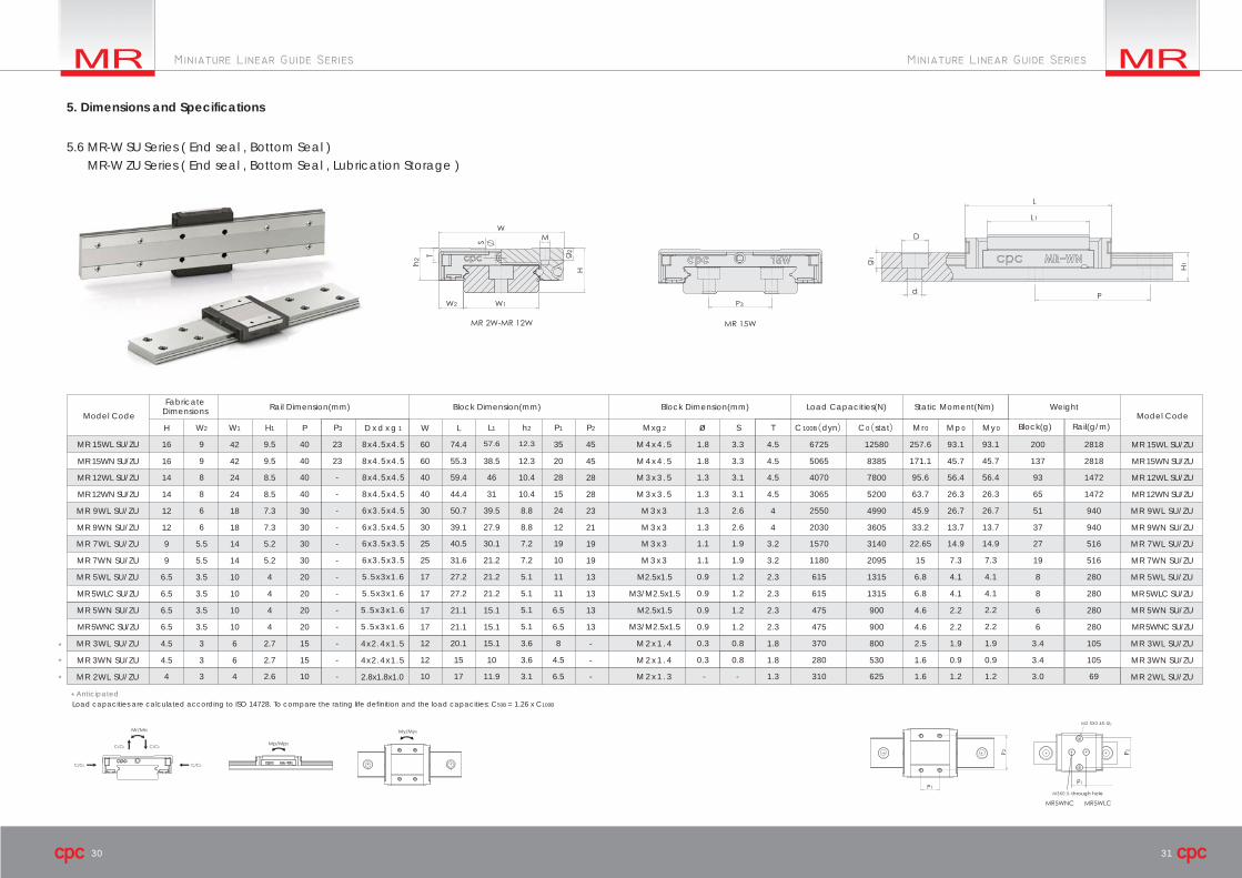
*
*
*
Block(g) Rail(g/m)Model Code Model Code
FabricateDimensions Rail Dimension(mm) Block Dimension(mm) Block Dimension(mm) Load Capacities(N) Static Moment(Nm) Weight
* Anticipated
5.6 MR-W SU Series ( End seal , Bottom Seal )MR-W ZU Series ( End seal , Bottom Seal , Lubrication Storage )
5. Dimensions and Specifications
Load capacities are calculated according to ISO 14728. To compare the rating life definition and the load capacities: C50B = 1.26 x C100B

through hole
32 33
MR 15WL SS/ZZ 16 9
9
8
8
6
6
9.5
9.5
40 8x4.5x4.5
8x4.5x4.5
8x4.5x4.5
8x4.5x4.5
6x3.5x4.5
6x3.5x4.5
6x3.5x3.5
6x3.5x3.5
5.5x3x1.6
5.5x3x1.6
5.5x3x1.6
5.5x3x1.6
40
23
23
-
-
-
-
-
-
-
-
-
-
-
-
-
40
40
60
60
74.5 57.6
55.8
59.6
44.5
50.7
39.1
40.5
31.8
15
27.2
27.2
20.1
38.5
46
31.1
39.4
27.9
30.1
21.2
10
21.2
21.2
15.1
40
40
30
30
25
25
17
17
12
12
12
12
10.1
10.1
8.6
8.6
7
7
5
5
3.5
3.5
35
20
28
15
24
12
19
10
11
11
8
4.5
45 M 4 x 4 . 5 1.9
1.9
1.4
1.4
1.3
1.3
1.1
1.1
0.9
0.9
0.3
0.3
3.3
3.3
3.1
3.1
2.6
2.6
1.9
1.9
1.2
1.2
0.8
0.8
4.5 6725
5065
4070
3065
2550
2030
1570
1180
615
615
370
280
12580 257.6
171.1
95.6
63.7
45.9
33.2
22.65
15
6.8
6.8
2.5
1.6
93.1
45.7
56.4
26.3
26.7
13.7
14.9
7.3
4.1
4.1
1.9
0.9
200
137
93
65
51
37
27
19
8
8
3.4
3.4
2818
2818
1472
1472
940
940
516
516
280
280
105
105
8385
7800
5200
4990
3605
3140
2095
1315
1315
800
530
4.5
4.5
4.5
4
4
3.2
3.2
2.3
2.3
1.8
1.8
M 4 x 4 . 5
M 3 x 3 . 5
M 3 x 3 . 5
M 3 x 3
M 3 x 3
M 3 x 3
M 3 x 3
M2.5x1.5
M3/M2.5x1.5
M3/M2.5x1.5
M 2 x 1 . 4
M 2 x 1 . 4
M 2 x 1 . 3
45
28
28
23
21
19
19
13
13
-
-
30
30
30
30
20
20
15
15
8.5
8.5
7.3
7.3
5.2
5.2
4
4
2.7
2.7
3.5
3.5
3
3
5.5
5.5
16
14
14
42
42
24
24
12
12
9
9
18
18
14
14
10
10
6
6
6.5
6.5
4.5
4.5
MR 15WN SS/ZZ
MR 12WL SS/ZZ
MR 12WN SS/ZZ
MR 9WL SS/ZZ
MR 9WN SS/ZZ
MR 7WL SS/ZZ
MR 7WN SS/ZZ
MR 5WL SS
MR 5WLC SS
MR 3WL SS/ZZ
MR 3WN SS/ZZ
MR 2WL SS/ZZ
4x2.4x1.5
4x2.4x1.5
2.8x1.8x1.0
21.1
21.1
15.1
15.1
17
17
5
5
6.5
6.5
0.9
0.9
1.2
1.2
475
475
4.6
4.6
2.2
2.2
6
6
280
280
900
900
2.3
2.3
M2.5x1.513
13
20
20
4
4
3.5
3.5
10
10
6.5
6.5
MR 5WN SS
MR 5WNC SS
MR 15WL SS/ZZ
MR 15WN SS/ZZ
MR 12WL SS/ZZ
MR 12WN SS/ZZ
MR 9WL SS/ZZ
MR 9WN SS/ZZ
MR 7WL SS/ZZ
MR 7WN SS/ZZ
MR 5WL SS
MR 5WLC SS
MR 3WL SS/ZZ
MR 3WN SS/ZZ
MR 2WL SS/ZZ
MR 5WN SS
MR 5WNC SS
H P W LD x d x g 1W2 W1 H1 h2L1 P1 P2P3 Mxg2 S T C100B dyn C0 stat Mr0 Mp0 My0ø
17 11.910 3 6.5 - - 310 1.6 1.2
93.1
45.7
56.4
26.3
26.7
13.7
14.9
7.3
4.1
4.1
1.9
0.9
2.2
2.2
1.2 3.0 696251.3-102.63 44
*
*
*
Block(g) Rail(g/m)Model Code Model Code
FabricateDimensions Rail Dimension(mm) Block Dimension(mm) Block Dimension(mm) Load Capacities(N) Static Moment(Nm) Weight
* Anticipated
5.7 MR-W SS Series (End seal)MR-W ZZ Series ( End seal , Lubrication Storage)
Load capacities are calculated according to ISO 14728. To compare the rating life definition and the load capacities: C50B = 1.26 x C100B
5. Dimensions and Specifications

34 35
MR 15WL SUE/ZUE 16 9
9
8
8
6
6
9.5
9.5
40 8x4.5x4.5
8x4.5x4.5
8x4.5x4.5
8x4.5x4.5
6x3.5x4.5
6x3.5x4.5
6x3.5x3.5
6x3.5x3.5
40
23
23
-
-
-
-
-
-
-
40
40
60
60
76
56.9
60.8
45.8
51.8
40.2
41.5
32.5
38.5
57.6
46
31
39.5
27.9
30.1
21.2
40
40
30
30
25
25
35
20
28
15
24
12
19
10
45 M 4 x 4 . 5 1.8
1.8
1.3
1.3
1.3
1.3
1.1
1.1
3.3
3.3
3.1
3.1
2.6
2.6
1.9
1.9
4.5 6725
5065
4070
3065
2550
2030
1570
1180
12580 257.6
171.1
95.6
63.7
45.9
33.2
22.65
15
93.1
45.7
56.4
26.3
26.7
13.7
14.9
7.3
203
140
96
68
51
37
27
19
2818
2818
1472
1472
940
940
516
516
8385
7800
5200
4990
3605
3140
2095
4.5
4.5
4.5
4
4
3.2
3.2
M 4 x 4 . 5
M 3 x 3 . 5
M 3 x 3 . 5
M 3 x 3
M 3 x 3
M 3 x 3
M 3 x 3
M 2 x 1 . 3
45
28
28
23
21
19
19
30
30
30
30
8.5
8.5
7.3
7.3
5.2
5.2
5.5
5.5
16
14
14
42
42
24
24
12
12
9
9
18
18
14
14
MR 15WN SUE/ZUE
MR 12WL SUE/ZUE
MR 12WN SUE/ZUE
MR 9WL SUE/ZUE
MR 9WN SUE/ZUE
MR 7WL SUE/ZUE
MR 7WN SUE/ZUE
MR 2WL SUE/ZUE
MR 15WL SUE/ZUE
MR 15WN SUE/ZUE
MR 12WL SUE/ZUE
MR 12WN SUE/ZUE
MR 9WL SUE/ZUE
MR 9WN SUE/ZUE
MR 7WL SUE/ZUE
MR 7WN SUE/ZUE
MR 2WL SUE/ZUE2.8x1.8x1.0
H P W LD x d x g 1W2 W1 H1 h2L1 P1 P2P3 Mxg2 S T C100B dyn C0 stat Mr0 Mp0 My0ø
17.5 11.9
13.1
13.1
11.2
11.2
9.4
9.4
7.6
7.6
3.410 6.5 - - 310 1.6 1.2
93.1
45.7
56.4
26.3
26.7
13.7
14.9
7.3
1.2 3.0 696251.3-1033 44
Model Code Model CodeFabricate
Dimensions Rail Dimension(mm) Block Dimension(mm) Block Dimension(mm) Load Capacities(N) Static Moment(Nm) Weight
Block(g) Rail(g/m)
5.8 MR-W SUE Series ( End seal , Bottom Seal , Reinforcement Plate )MR-W ZUE Series ( End seal , Bottom Seal , Reinforcement Plate , Lubrication Storage )
5. Dimensions and Specifications
Load capacities are calculated according to ISO 14728. To compare the rating life definition and the load capacities: C50B = 1.26 x C100B

36 37
MR 15WL EE/EZ 16 9
9
8
8
6
6
9.5
9.5
40 8x4.5x4.5
8x4.5x4.5
8x4.5x4.5
8x4.5x4.5
6x3.5x4.5
6x3.5x4.5
6x3.5x3.5
6x3.5x3.5
40
23
23
-
-
-
-
-
-
-
40
40
60
60
76
56.9
60.8
45.8
51.8
40.2
41.5
32.5
57.6
38.5
46
31
39.5
27.9
30.1
21.2
40
40
30
30
25
25
12.8
12.8
10.9
10.9
9.2
9.2
7.5
7.5
35
20
28
15
24
12
19
10
45 M 4 x 4 . 5 1.8
1.8
1.3
1.3
1.3
1.3
1.1
1.1
3.3
3.3
3.1
3.1
2.6
2.6
1.9
1.9
4.5 6725
5065
4070
3065
2550
2030
1570
1180
12580 257.6
171.1
95.6
63.7
45.9
33.2
22.65
15
93.1
45.7
56.4
26.3
26.7
13.7
14.9
7.3
203
140
96
68
51
37
27
19
2818
2818
1472
1472
940
940
516
516
8385
7800
5200
4990
3605
3140
2095
4.5
4.5
4.5
4
4
3.2
3.2
M 4 x 4 . 5
M 3 x 3 . 5
M 3 x 3 . 5
M 3 x 3
M 3 x 3
M 3 x 3
M 3 x 3
M 2 x 1 . 3
45
28
28
23
21
19
19
30
30
30
30
8.5
8.5
7.3
7.3
5.2
5.2
5.5
5.5
16
14
14
42
42
24
24
12
12
9
9
18
18
14
14
MR 15WN EE/EZ
MR 12WL EE/EZ
MR 12WN EE/EZ
MR 9WL EE/EZ
MR 9WN EE/EZ
MR 7WL EE/EZ
MR 7WN EE/EZ
MR 2WL EE/EZ
MR 15WL EE/EZ
MR 15WN EE/EZ
MR 12WL EE/EZ
MR 12WN EE/EZ
MR 9WL EE/EZ
MR 9WN EE/EZ
MR 7WL EE/EZ
MR 7WN EE/EZ
MR 2WL EE/EZ2.8x1.8x1.0
H P W LD x d x g 1W2 W1 H1 h2L1 P1 P2P3 Mxg2 S T C100B dyn C0 stat Mr0 Mp0 My0ø
17.5 11.910 3.3 6.5 - - 310 1.6 1.2
93.1
45.7
56.4
26.3
26.7
13.7
14.9
7.3
1.2 3.0 696251.3-1033 44
Model Code Model Code
FabricateDimensions Rail Dimension(mm) Block Dimension(mm) Block Dimension(mm) Load Capacities(N) Static Moment(Nm) Weight
Block(g) Rail(g/m)
5.9 MR-W EE Series ( End seal, Reinforcement Plate )MR-W EZ Series ( End seal , Reinforcement Plate , Lubrication Storage )
Load capacities are calculated according to ISO 14728. To compare the rating life definition and the load capacities: C50B = 1.26 x C100B
5. Dimensions and Specifications

38 39
MR 15WL EU/UZ 16 9
9
8
8
6
6
9.5
9.5
40 8x4.5x4.5
8x4.5x4.5
8x4.5x4.5
8x4.5x4.5
6x3.5x4.5
6x3.5x4.5
40
23
23
-
-
-
-
40
40
60
60
76
56.9
60.8
45.8
51.8
40.2
38.5
46
31
39.5
27.9
40
40
30
30
35
20
28
15
24
12
45 M 4 x 4 . 5 1.8
1.8
1.3
1.3
1.3
1.3
3.3
3.3
3.1
3.1
2.6
2.6
4.5 6725
5065
4070
3065
2550
2030
12580 257.6
171.1
95.6
63.7
45.9
33.2
93.1
45.7
56.4
26.3
26.7
13.7
203
140
96
68
51
37
2818
2818
1472
1472
940
940
8385
7800
5200
4990
3605
4.5
4.5
4.5
4
4
M 4 x 4 . 5
M 3 x 3 . 5
M 3 x 3 . 5
M 3 x 3
M 3 x 3
45
28
28
23
21
30
30
8.5
8.5
7.3
7.3
16
14
14
42
42
24
24
12
12
18
18
MR 15WN EU/UZ
MR 12WL EU/UZ
MR 12WN EU/UZ
MR 9WL EU/UZ
MR 9WN EU/UZ
MR 15WL EU/UZ
MR 15WN EU/UZ
MR 12WL EU/UZ
MR 12WN EU/UZ
MR 9WL EU/UZ
MR 9WN EU/UZ
H P W LD x d x g 1W2 W1 H1 h2L1 P1 P2P3 Mxg2 S T C100B dyn C0 stat Mr0 Mp0 My0ø
13.1
13.1
11
11
9.5
9.5
93.1
45.7
56.4
26.3
26.7
13.7
57.6
Model Code Model Code
FabricateDimensions Rail Dimension(mm) Block Dimension(mm) Block Dimension(mm) Load Capacities(N) Static Moment(Nm) Weight
Block(g) Rail(g/m)
5.10 MR-W EU Series ( End seal , Reinforcement Plate , Stainless Bottom Seal )MR-W UZ Series ( End seal , Reinforcement Plate , Stainless Bottom Seal , Lubrication Storage )
5. Dimensions and Specifications
Load capacities are calculated according to ISO 14728. To compare the rating life definition and the load capacities: C50B = 1.26 x C100B
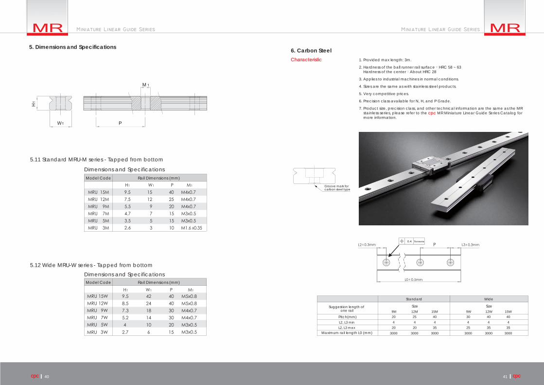
5.11 Standard MRU-M series - Tapped from bottom
5.12 Wide MRU-W series - Tapped from bottom
6. Carbon SteelCharacteristic 1. Provided max length: 3m.
2. Hardness of the ball runner rail surface:HRC 58 ~ 63 Hardness of the center:About HRC 28
3. Applies to industrial machines in normal conditions.
4. Sizes are the same as with stainless steel products.
5. Very competitive prices.
6. Precision class available for N, H, and P Grade.
7. Product size, precision class, and other technical information are the same as the MR stainless series, please refer to the cpc MR Miniature Linear Guide Series Catalog for more information.
Transverse
9M 12M 15M2520
20 2520 35 35 35
40
300030003000
9W 12W 15W4030 40
44 4 4 4 4
300030003000
L2, L3 minL2, L3 max
Standard Wide
Size SizeSuggestion length of one rail
Pitch(mm)
Maximum rail length L0 (mm)
Groove mark forcarbon steel type
5. Dimensions and Specifications
Dimensions and Specifications
Dimensions and Specifications
Model Code Rail Dimensions (mm)
Model Code Rail Dimensions (mm)
40 41

ST Miniature Stroke Slide series
42 43
6. Carbon Steel
D
P3
g1
W1
d
H1
PW1
d
D
g1
H1
MR15WMR-M
MR-9W/12W
MRU-9W/12W MRU15W
MRU-M
P3
W1
H1
M1
W1
H1
M1
P
Standard Rail
Tapped Rail
Standard MR-M series Rail Wide MR-W series Rail
MR 15M 9.57.55.5
15129
40PW1H1
2520
930602301
6x3.5x4.56x3.5x4.56x3.5x3.5
MR 12MM R 9 M
Dxdxg1
Model Code Rail Dimensions(mm) Weight(g/m)
9.57.55.5
15129
40PW1H1
2520
930602301
M1
M4x0.7M4x0.7M4x0.7
MRU 15MMRU 12MMRU 9M
Model Code Rail Dimensions(mm) Weight(g/m)
PW1H1
MR 15WMR 12WMR 9W
9.58.57.3
422418
28181472940
404030
23
--
8x4.5x4.58x4.5x4.56x3.5x4.5
Dxdxg1P3
Model Code Rail Dimensions(mm) Weight(g/m)
PW1H1
MRU 15WMRU 12WMRU 9W
9.58.57.3
422418
28181472940
404030
23
--
M1P3
M5x0.8M5x0.8M4x0.7
Model Code Rail Dimensions(mm) Weight(g/m)
Standard MRU-M series - Tapped from bottom Wide MRU-W series - Tapped from bottom

44 45
The ST Miniature Stroke Slide Series is designed with two rows of balls. The ball track has a gothic profile design with a 45 degree contact angle to achieve equal load capacity in a mono block. This provides more space for the larger rolling elements while enhancing the load and moment capacity.
The steel balls of the ST miniature stroke slide seriesroll on the rail without recirculation, resulting inexcellent running behavior, smoothness, low friction,and high accuracy without vibration.
The ST Miniature Stroke Slide Series adopts a pair of end plates into the design. Both the center rail and bearing block sides have a plateinstalled that prevents the linear guide from over-stroking.
The mounting of the ST Miniature Stroke Slide Seriesis accomplished by fitting the fixing screw downwardinto the count bore of the rail by intersecting thehole pattern on the block and cage within thehole pitch. The one piece cage therefore does not influence the mounting of the rail while the preload is preset by ball sorting.
The ST Miniature Stroke Slide Series can withstand temperatures of up to 150 oC.There are two treatment options for higher temperature applications:
Applying treatments for higher temperature applications will reduce the load capacity.
The ST Miniature Stroke Slide Series is composed ofquenched hardened process stainless steel for therail, block, and steel balls. The block plate andscrews are made of stainless steel as well -- providinga great model for maintenance and inspectionapplications.
1. Product Introduction
High load and high momentcapaity
High running accuracy and smoothness
Temperature
Dual plate design Easy mounting
Anti-corrosion feature
T1:200oCT2:300oC

46 47
Lubrication of the ST Miniature Stroke SlideSeries can be performed by adding thelubricant onto the raceway of the rail.
The ST Miniature Stroke Slide series has two preload classes, V0 and V1, as described in the MR miniature linear guide series preload table.
Rating life LLubrication
The rating life of the ST Miniature StrokeSlide Series can be calculated by formulas (19) and (20), in accordance with ISO 14728-1.
Height and Chamfered ReferenceEdgeThe tables for the chamfered reference edgecorner and the height of the reference edgefor the MR Miniature Linear Guide Series arealso suitable for the ST Miniature Stroke SlideSeries.
3. Ordering Information
An example of the ST MiniatureStroke Slide Series part numberingsystem is shown above.
The inaccuracy of the mounting surfaces will affect therunning accuracy and reduce the operating lifetime ofthe ST Miniature Stroke Slide. If the inaccuracies of themounting surface exceed the values calculated by formulas (15), (21), and (17), the lifetime will be shortened, as calculated by formulas (19) and (20).
2. Technical Information
Accuracy PreloadThe ST Miniature Stroke Slide Series hasthree grades for accuracy. Precision (P),High (H) and Normal (N).
Rating life calculation Short stroke factor diagram
Geometric and positional accuracy of themounting surface
The mounting surface geometricand positional accuracy factor Ordering designation
Ordering Designation

48 49
4. Dimensions and Specifications

50
A linear guide is a category of rolling guidance systems. By using unlimited recirculating stainless steel balls that operate between the raceways of the rail and the runner block, the carriage achieves high precision and low friction linear movement. If the linear guides do not have sufficient lubrication, rolling friction will increase, causing wear and shortened linear guide lifespan.
cpc has added and embedded PU lubricant storage pads to prolong the life of the linear guide; the pads directly contact and lubricatethe rolling balls. This design supplies sufficient lubrication even in short stroke operations.
cpc’s design, due to the embedded pads absorption and retention capabilities, results in a product that features a long operation lifeand long-term lubrication.
Lubrication Storage Pad Testing Report
Following are the results of cpc's in-house testing.
Lubrication storage pad
Total continuous running time of 3,820 hoursand travel distance of 8,802 kilometers
Inspection interval 1
Inspection interval 2
Inspection interval 3
Inspection intervals 1 and 2: Lubrication Maintained Inspection interval 3: Lubricant residue
Upward lubrication storagepads in good condition.Lubricant supply in goodcondition.No wear on the runningprofile of the rail.
Downward lubrication storagepads in good condition.Lubricant supply in good condition.
Dried lubricant residue andbreakage on the downward lubrication storage pads.
Test results at inspection intervals
Inspection interval 3Inspection intervals 1 and 2
Some rail profiles have dried lubricant present.
Tested products: AR15 blocks with lubrication storage pads, 8 pieces, andAR15 rails, N accuracy grade, 1500mm Length, 4 pieces
Dried lubricant residue andbreakage on the upwardlubrication storage pads
AR15 Lubrication Storage Pad Testing Data Testing equipment
Test Summary
Testing resultDried lubricant residue started appearing on rail profile, PU pads, and ball
retainer of the tested blocks
Volume of lubriant
Plastic parts and end seal in good condition
Plastic parts in good condition End seal in good condition
Total continuous running time of 3820 hours and travel distance of 8802 kilometers.Out of eight test blocks, dried lubricant residue appearedon 2 blocks and 1 rail.Dried lubricant residue is indicative of a need for relubricationand thus lengthens the operational life of the linear guide.