Embed Size (px)
Citation preview

Reply Refer To: FO-2-1 May *6. 1988
Chevron U.S.A. Inc. Attention: Hr. K. D. Schenck Post Offlct Box 61590 lew fYleans. Louisiana 70161
Gentl MMM
Reference 1s taade to your Supplemental Plan of Exploration rectiveu1 Hay 12. 198fi. for L*Ait QCS-fl 5603. Block 132. South Tlafcal ler Area. This plan Includes the act ivi t ies proposed for Well flo. 2.
In accordance with 30 CFR 2SC.J4. revised December .3 . 1979. and our Utter dated January 2% 1979. this plan Is hereby determined to be co-op lete and 1s now being considered for approval.
Your plan cfifttrjul njffabQT iX^'21Z7 and should he referencea 1n your cor., jnl cation ana correspondence concerning this plan.
Sincerely yours.
Sgd.) A Oonafd Girorr D. J . Bourgeois Regional Supervisor Field Operations
bcc: Lease OCS-G 5603 (OPS-3-2) (FILE ROOM) ^OPS-3-4 w/Publ1c Info. Copy of the plan (PUBLIC RECORDS)
rCJoseph:cck:05/26/88:poeco©
*ogra,n Serv/ces
1988

Chevron U.S.A. Inc. P. 0. Box 61590. New Orleans. LA. 70161
May 9, 1988
Supplemental Plan of Exploration South Timbalier Blk 132 OCS-G-5603 #2
U. S. Department of the I n t e r i o r
CERTIFIED MAIL - RECEIPT REQUESTED
Minerals Management Service 1 i wm++ 1201 Elmwood Park Boulevard New Orleans, LA 70123-2394
Gentlemen:
Chevron U.S.A. Inc., as the operator, submits this proposed Supplemental Plan of Exploration for South Timbalier Block 132, OCS-G-5603.
This program provides for the further development of activities for OCS-G-5603. We plan to resume our activity by drilling one deviated well through a drive pipe with no surface structure. If the well is successful, plans are to set a structure over the surface.
Location of Proposed Wells
Surface Location: 2000' FNL and 1450' FWL South Timbalier Blk 132
Geological and Geophysical Data
We plan to utilize a drill barge similar to the Ocean Columbia to drill this well. The drilling barge will provide well control and containment pollution control, fire fighting and Ufe saving equipment, and a sewage treatment systan to comply with MMS and U.S. Coast Guard requirements. A sketch of the type of drilling barge to be used 1s attached.
The onshore support and storage facilities required for the proposed plan are Chevron U.S.A. Inc.'s existing base facilities located at Leeville, Louisiana. The existing base has adequate facilities for marine and air transportation to handle the equipment for this additional development location.
AVAILABU COPV
PUBLIC INFORMATinw
2832/12027/0IL Eastern Region, Exploration, Land & Production
U.S. Dept. of the Interior - 2 - May 9, 1988
Chevron U.S.A. Inc.'s Oil Spill Contingency Manual has previously been filed with MMS which provides the specific details to be employed for preventing, reporting, and combating Incidents of pollution.
Chevron U.S.A. Inc. is a member of the Clean Gulf Associates which maintains high volume cleanup equipment at Its base at Leeville, Louisiana. The response time for Its deployment to the location 1s approximately six (6) hours. Chevron U.S.A. Inc.'s 011 Spill Contingency Manual was approved by MMS on November 10, 1986.
In accordance with 30 CFR-250 34-2, we enclose the following documents:
Chevron U.S.A. Inc. believes that the geological structure map and the schematic cross-section map submitted are exempt from disclosures under the Freedom of Information Act and should, therefore, not be made available to the public or provided to any affected state or to the executive of any local government.
We plan to commence operations June 15, 1988. Anticipated time to drill OCS-G-5603 #2 1s ±35 days.
If any further information is required, please contact S. A. Rondeno at (504) 569-3729.
Location Plat Vicinity Map Drilling Barge Specifications - Ocean Columbia Air Emissions Report
Very truly yours,
cc: Houma District
BEST *VAILABL E COPy PUBLIC INFORMATION
2832/12027/0IL
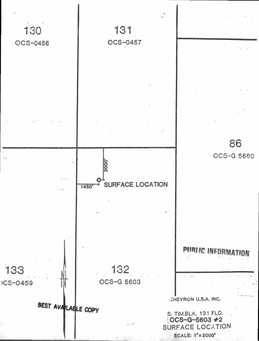
130 OCS-0456
133 >CS-0459
131 OCS-0457
i4go»-< SURFACE LOCATION
132 OCS-G 5603
86 OCS-G 5660
WMHIC INFORMATION
COPV
CHEVRON U.S-A. INC.
S. TIM.BLK. 131 FLD. IOCS-G-5603 * 2
SURFACE LOCATION SCALE: 1*s2000'
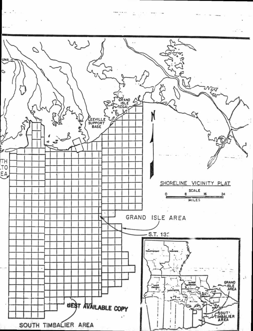
SHORELINE VICINITY PLAT SCALE
0 8 « 24
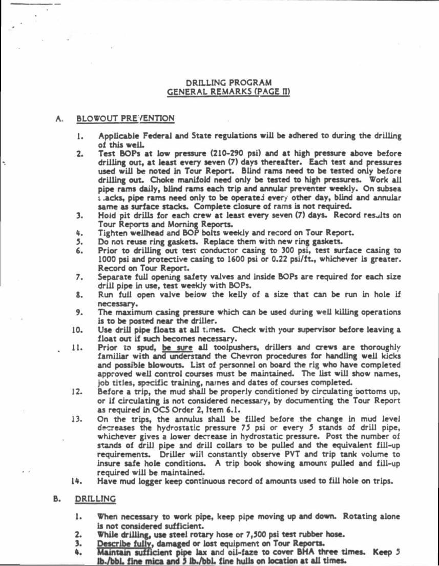
DRILLING PROGRAM GENERAL REMARKS (PAGE Fl)
BLOWOUT PREVENTION
1. Applicable Federal and State reguiations wili be adhered to during the drilling ol this weiL
2. Test BOPs at low pressure (210-290 psi) and at high pressure above before drilling out, at least every seven (7) days thereafter. Each test and pressures used will be noted in Tour Report. Blind rams need to be tested oniy before drilling out. Choke manifold need oniy be tested to high pressures. Work all pipe rams daily, blind rams each trip and annular preventer weekly. On subsea i .acks, pipe rams need only to be operated ever/ other day, blind and annular same as surface stacks. Complete closure of rams is not required.
3. Hold pit drills for each crew at least every seven (7) days. Record results on Tour Reports and Morning Reports.
4. Tighten wellhead and BOP bolts weekly and record on Tour Report. 3. Do not reuse ring gaskets. Replace them with new ring gaskets. 6. Prior to drilling out test conductor casing to 300 psi, test surface casing to
1000 psi and protective casing to 1600 psi or 0.22 psi/ft., whichever is greater. Record on Tour Report.
7. Separate full opening safety valves and inside BOPs are required for each size drill pipe in use, test weekly with BOPs.
8. Run full open vaive beiow the kelly of a size that can be run in hole if necessary.
9. The maximum casing pressure which can be used during well killing operations is to be posted near the driller.
10. Use drill pipe floats at all t.rnes. Check with your supervisor before leaving a float out if such becomes necessary.
11. Prior to spud, be sure all toolpushers, drillers and crews are thoroughly familiar with and understand the Chevron procedures for handling well kicks and possible blowouts. List of personnel on board the rig who have completed approved well control courses must be maintained. The list will show names, job titles, specific training, names and dates of courses completed.
12. Before a trip, the mud shall be properly conditioned by circulating bottoms up, or If circulating is not considered necessary, by documenting the Tour Report as required in OCS Order 2, Item 6.1.
13. On the trips, the annulus shall be filled before the change in mud level decreases the hydrostatic pressure 73 psi or every 3 stands of drill pipe, whichever gives a lower decrease in hydrostatic pressure. Post the number of stands of drill pipe snd drill collars to be pulled and the equivalent fill-up requirements. Driller will constantly observe PYT and trip tank volume to insure safe hole conditions. A trip book showing amount pulled and fill-up required will be maintained.
14. Have mud logger keep continuous record of amounts used to fill hole on trips.
DRILLING
1. When necessary to work pipe, keep pipe moving up and down. Rotating alone is not considered sufficient.
2. While drilling, usa steel rotary hose or 7,300 psi ttst rubber hose. 3. Describe fully, damaged or lost equipment on Tour Reports. %. Maintain sufficient pipe lax and oil-faze to cover BHA thrtt times. Keep 3
Ib./bbL fint mica and 3 ib./bbL fine hulls on location at all time*.
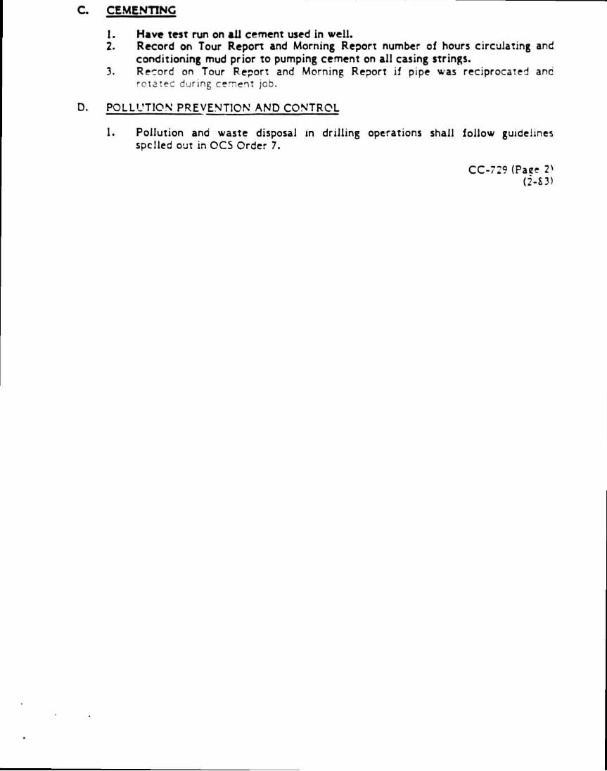
C CEMENTING
1. Have test run on ai l cement used in wel l . 2. Record on Tour Reporl and Morning Report number of hours circulating and
conditioning mud prior to pumping cement on all casing strings. 3. Record on Tour Report and Morning Report if pipe was reciprocated anc
rotateC during cement job.
D. POLLUTION PREVENTION AND CONTROL
1. Pollution and waste disposal in dr i l l ing operations shall fol low guidelines spelled out in OCS Order 7.
CC-729 (Paee 2̂ (2-S3)
WELL NAME _ FIELD DRILLING RIG
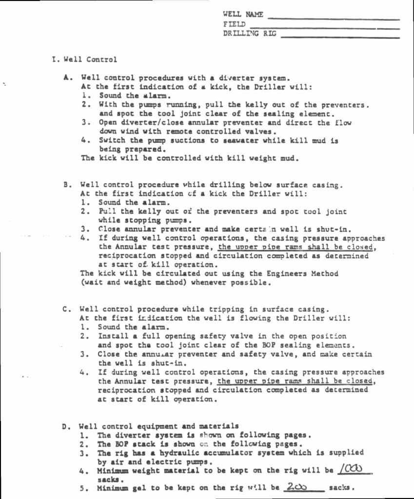
. Well Control
A. Woll control procedures with a diverter system. AC Che first indication of a kick, Che Driller w i l l : 1. Sound che alarm. 2. With che pumps running, pull che kelly out of the preventers,
and spoc che cool Joint clear of che sealing e lemen c • 3. Open divorcer/close annular preventer and direct che flow
down wind with remote controlled valves. 4. Switch Che pump suctions Co saawacar while k i l l mud is
being prepared. The kick wil l be controlled with k i l l weight mud.
B. Well control procedure while drilling below surface casing. Ac Che first indication cf a kick che Driller v i l l : 1. Sound che alarm. 2. Pull Che kelly ouc or the preventers and spot tool joint
while stopping pumps. 3. Close annular preventer and make carta\n v e i l ls shut-in. 4. I f during v e i l control operations, che casing pressure approaches
che Annular Case pressure, the upper pipe rams shall be closed, reciprocation stopped and circulation completed as determined at start of. k i l l operation.
The kick v i l l be circulated out using Che Engineers Method (vait and velght method) vhenever possible.
C. Well control procedure vhile tripping in surface casing. At thc f i r s t indication the veil ls floving the Driller v i l l : 1. Sound the alarm. 2. Install a f u l l opening safety valve in the open position
and spot the tool joint clear of the BOP sealing elements. 3. Close the annular preventer and safety valve, and make certain
the veil is shut-in. 4. I f during v a i l control operations, the casing pressure approaches
the Annular test pressure, the upper pipe rams shall be closed, reciprocation stopped and circulation completed as determined at start of k i l l operation.
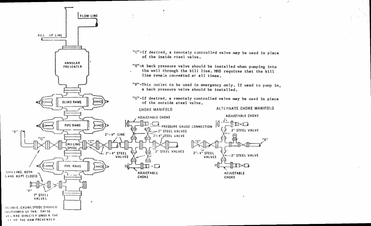
D. Well control equipment and materials 1. The diverter syatem ls «uovn on following pages. 2. The BOP stack is shown or. Che following pages. 3. Tha rig has a hydraulic accumulator system vhich ls supplied
by air and electric pumps. 4. Minimum weight material to be kept on che rig w i l l be /CEO
sacks. 5. Minimum gal Co be kept on Che rig v i l l be 2.00 sacks.
f i l l UP I JNE
f LOW LINE
3
ANNULAR PREVENTER
"E" r - 4 " LINE
fl MI | l INC. BOTH S AHE KEPT CLOSFO
S T I l l VALVES
r STF IL VALVES
IIV.IUI C. CASING SPOOL SMUMl I) "OSllMlNIII Sll IMA. TMI SE v r . AHE OiRlCTl V UNIH M TMf
I I III I Ml HAM PRE VI Ni l M
1
MC"-If desired, a remotely controlled valve may be used ln place of the Inside Pteel valve.
MEM-A back pressure valve should be installed when pumping Into the well through the k i l l line. >ttS requires thet the k i l l line remain connected ar a l l times.
"FM-This outlet to be used in emergency only. If used to pump ln, a back pressure valve should be Installed.
"C"-If desired, a remotely controlled valve may be used ln place of the outside steel valve.
ALTERNATE CHOKE MANIFOLD CHOKE MANIFOLD
ADJUSTABLE CHOKE
- a PRESSURE GAUGE CONNECTION 2" STEEL VALVES
2 — 4**iTEEl vALVE
ADJUSTABLE CHOKE
7" STEEL VALVE
7" STEEL VALVES ? " - 4 " STEEL VALVES
ADJUSTABLE CHOKE
ADJUSTABLE CHOKE
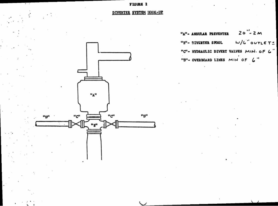
F10 UEI 2
DIVERTER SYSTEM IttOK-UP
1.
I I A H
r 1 > i i imi
2
" A " - ANUUIAR PREVENTER 2 O - Z M
"B"- £IV£RTER SPOOL U j / U " o u T L 6 T «
"Cf- HYDRAULIC DIVERT VALVES MlrJ. Of (0" #
"D"- OVERBOARD LINES MIM OF & "
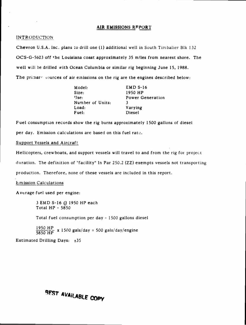
AIR EMISSIONS RFPORT
INTRODUCTION
Chevron U.S.A. Inc. plans :o drill one (1) additional well in South Timbalier Blk 132
OCS-G-5603 off rhe Louisiana coast approximately 35 m!les from nearest shore. The
well will be drilled with Ocean Columbia or similar rig beginning June 15, 1988.
The pri.nar sources of air emissions on the rig are the engines described below:
Model: EMDS-16 Size: 1950 HP Use: Power Generation Number of Units: 3 Load: Varying Fuel: Diesel
Fuel consumption records show the rig burns approximately 1500 gallons of diesel
per day. Emission calculations are based on this fuel race.
Support Vessels and Aircraft
Helicopters, crewboats, and support vessels will travel to and from the rig for project
duration. The definition of "facility" In Par 250.2 (ZZ) exempts vessels not transporting
production. Therefore, none of these vessels are included in this report.
Emission Calculations
Average fuel used per engine:
3 EMD S-16 @ 1950 HP each Total HP - 5850
Total fuel consumption per day - 1500 gallons diesel
IQCfl H P
x 1500 gals/day = 500 gals/day/engine
Estimated Drilling Days: ±35
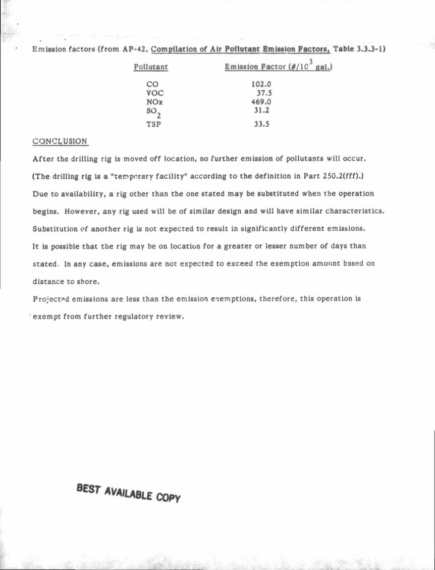
Emission factors (from AP-42, Compilation of Air Pollutant Emission Pactors, Table 3.3.3-1)
Pollutant Emission Factor (#/lC gal.)
CO 102.0 VOC 37.5 NOx 469.0 SO. 31.2
TSP 33.5
CONCLUSION
After the drilling rig is moved off location, no further emission of pollutants will occur.
(The drilling rig is a "temporary facility" according to the definition in Part 250.2(fff).)
Due to availability, a rig other than the one stated may be substituted when the operation
begins. However, any rig used will be of similar design and will have similar characteristics.
Substitution of another rig is not expected to result in significantly different emissions.
It is possible that the rig may be on location for a greater or lesser number of days than
stated. In any case, emissions are not expected to exceed the exemption amount based on
distance to shore.
Projected emissions are less than the emission exemptions, therefore, this operation is
exempt from further regulatory review.
8 « T AVAJUSLE copy
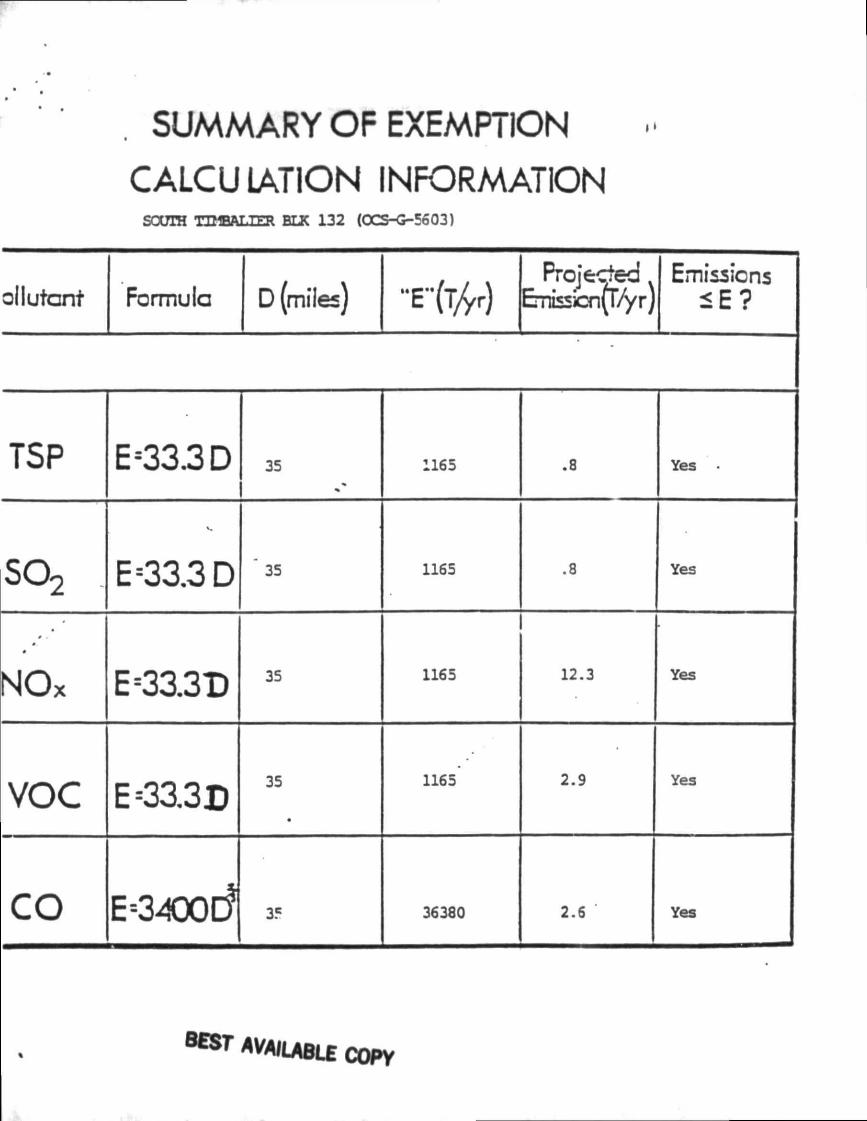
SUMMARY OF EXEMPTION
CALCULATION INFORMATION SOTJIH TU1BAXIER BLK 132 (OCS-G-5603)
ollutont Formula D (miles) Emissions
<E?
TSP E<33.3D 35 1165 .8 Yes •
so2 . E=33.3D " 35 1165 .8 Yes
•
NOx E<33.3D 35 1165 12.3 Yes
VOC E33.3D 35
•
1165 2.9 Yes
CO E-3400C? 35 36380 2.6 Yes
MAILABLE COPY
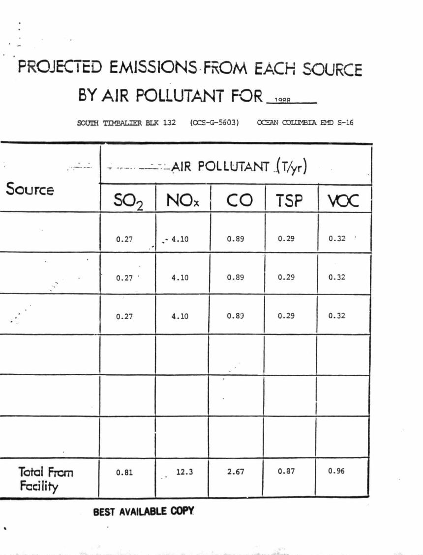
PROJECTED EMISSIONS FROM EACH SOURCE
BY AIR POLLUTANT F O R ^ SOOTH TIMBALIER BLK 132 (OCS-G-5603) OCEAN COLUMBIA EMD S-16
Source ™ ~ -" AIR POLLUTAiNT (T/yr)
Source so2 NOx CO TSP VOC
0.27 4.10 0.89 0.29 0.32 '
0.27 ' 4.10 0.89 0.29 0.32
• #
0.27 4.10 0.89 0.29 0.32
•
Total From Facility
0.81 12.3 2.67 0.87 0.96
BEST AVAILABLE COPY
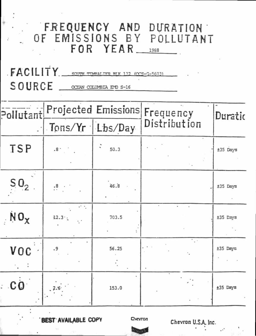
FREQUENCY AND DURATION OF EMISSIONS BY POLLUTANT
FOR YEAR_ 1968
S O U R C E OCEAN COLUMBIA E21D S-16
Pollutant •
Projected Emissions Frequency Duratic Pollutant • Tpns/Yr Lbs/Day Distribution
Duratic
TSP .8*
•
50.3 • ±35 Days
S o2 •_
•
.8 • 46.8
•
-• ±35 Days
NOx
• •
12.3 -•
703.5
•
±35 Days
VOC •
•
.9 56.25
•
•
• ±35 Days
•
•
153.0 •
±35 Days
BEST AVAILABLE COPY CHrvrsn Chevron U.SA Inc.
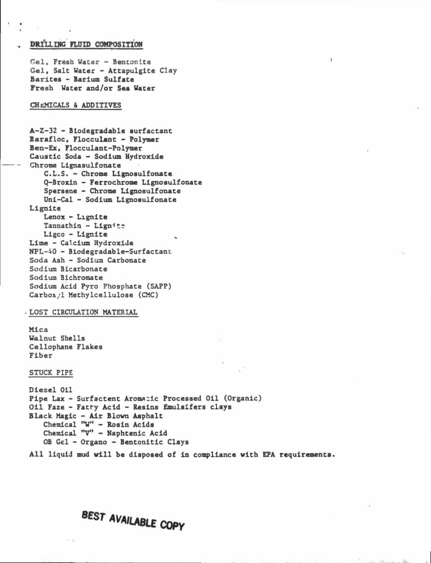
DRILLING FLUID COMPOSITION
G e l , Fresh Water - Bentonlte Gel , Salt Vater - At tapulgl te Clay Barl tea - Barium Sulfate Fresh Water and /o r Sea Water
CHEMICALS & ADDITIVES
A-Z-32 - Biodegradable surfactant Baraf loc , Flocculant - Polymer Ben-Ex, Flocculant-Polymer Caustic Soda - Sodium Hydroxide Chrome Llgnasulfonate
C.L.S. - Chrome Lignosulfonate Q-Broxin - Ferrochrome Lignosulfonate Spersene - Chrome Lignosulfonate Uni-Cal - Sodium Lignosulfonate
L i g n i t e Lenox - L i g n i t e Tannathin - Llgn*t* Llgco - L i g n i t e
Lime - Calcium Hydroxide NPL-40 - Biodegradable-Surfactant Soda Ash - Sodium Carbonate Sodium Bicarbonate Sodium Bichromate Sodium Acid Pyro Phosphate (SAPP) Carbox/1 Methylcellulose (CMC)
. LOST CIRCULATION MATERIAL
Mica Walnut Shells Cellophane Flakes Fiber
STUCK PIPE
Diesel Oil Pipe Lax - Surfactcnt Aromatic Processed Oil (Organic) Oil Faze - Fatry Acid - Resins Emulslfers clays Black Magic - Air Blown Asphalt
Chemical "W" - Rosin Acids Chemical "V" - Naphtenic Acid OB Gel - Organo - Bentonitic Clays
A l l liquid mud v i l l be disposed of in compliance with EPA requirements.
MAILABLE COPY


