Embed Size (px)
Citation preview

C
Cc
1
2
R3
P(
4
5
3
1
M6
p7
i8
c9
b10
b11
a12
i13
t14
p15
d16
m17
p18
i19
a20
p21
s22
p23
t24
i25
a26
c27
0d
RO
OF
ARTICLE IN PRESSHERD 161 1–14
chemical engineering research and design x x x ( 2 0 0 8 ) xxx–xxx
Contents lists available at ScienceDirect
Chemical Engineering Research and Design
journa l homepage: www.e lsev ier .com/ locate /cherd
FD modeling of gas–liquid–solid mechanically agitatedontactor
anganathan Panneerselvam, Sivaraman Savithri ∗, Gerald Devasagayam Surenderrocess Engineering & Environmental Technology Division, National Institute for Interdisciplinary Science and Technology (CSIR)Formerly Regional Research Laboratory), Thiruvananthapuram 695019, India
a b s t r a c t
In the present work, CFD simulations have been carried out to study solid suspension in gas–liquid–solid mechani-
cally agitated contactor using Eulerian–Eulerian multifluid approach along with standard k − ε turbulence model. A
multiple frame of reference (MFR) has been used to model the impeller and tank region. The CFD model predictions
are compared qualitatively with the literature experimental data and quantitatively with our experimental data. The
present study also involves the effects of impeller design, particle size and gas flow rate on the critical impeller speed
D Pfor solid suspension in gas–liquid–solid mechanically agitated contactor. The values predicted by CFD simulation for
critical impeller speed agrees well with experimental data for various operating conditions.
© 2008 The Institution of Chemical Engineers. Published by Elsevier B.V. All rights reserved.
Keywords: Stirred tank; CFD; Eulerian–Eulerian; Gas–liquid–solid; Critical impeller speed
28
29
30
Q1 31
32
33
34
35
36
37
38
39
40
41
42
43
44
45
46
47
48
generated by different types of impellers in a fully baffled 49
CO
RR
EC
TE
. Introduction
echanically agitated reactors involving gas, liquid and solidhases have been widely used in the chemical industries and
n mineral processing, wastewater treatment and biochemi-al industries. This is one of the widely used unit operationsecause of its ability to provide excellent mixing and contactetween the phases. Despite their widespread use, the designnd operation of these agitated reactors remain a challeng-ng problem because of the complexity encountered due tohe three-dimensional (3D) circulating and turbulent multi-hase flow in the reactor. An important consideration in theesign and operation of these agitated reactors is the deter-ination of the state of full suspension, at which point no
articles reside on the vessel bottom for a long time. Regard-ng solid suspension, basically three main suspension statesre observed in a mechanically agitated reactor namely; com-lete suspension, homogeneous suspension and incompleteuspension. A suspension is considered to be complete if noarticle remains at rest on the bottom of the tank for morehan 1 or 2 s. The determination of such complete suspensions critical, since only under this condition the total surface
UN
Please cite this article in press as: Panneerselvam, R., et al., CFD modelinDes (2008), doi:10.1016/j.cherd.2008.08.008
rea of the particles is effectively utilized. One of the mainriteria which is often used to investigate the solid suspen-
∗ Corresponding author. Tel.: +91 471 2515264; fax: +91 471 2491712.E-mail address: [email protected] (S. Savithri).Received 4 August 2008; Accepted 8 August 2008
263-8762/$ – see front matter © 2008 The Institution of Chemical Engioi:10.1016/j.cherd.2008.08.008
sion is the critical impeller speed (Njs) at which solids arejust suspended. The most widely used criterion for the criticalimpeller speed in the operation of solid–liquid stirred reactorsis still based on the pioneering work of Zwietering (1956) forthe just-suspension condition.
In some of the applications like hydrogenation, catalyticoxidation and chlorination processes, the solids are sus-pended in the presence of gas, in which the solids act as acatalyst or undergoes a chemical reaction in mechanically agi-tated reactors. In these type of reactors, the agitator plays thedual role of keeping the solids suspended, while dispersingthe gas uniformly as bubbles. The critical impeller speed (Njsg)for solid suspension in the presence of gas medium is themain parameter used to characterize the hydrodynamics ofthese reactors. The critical impeller speed for gas–liquid–solidmechanically agitated reactors mainly depend on severalparameters such as particle settling velocity, impeller design,impeller diameter, sparger design, and its location.
The designing and scaling up of mechanically agitatedreactors are generally based on semi-empirical methods.For example the flow regime map for gas–liquid–solid flows
CHERD 161 1–14g of gas–liquid–solid mechanically agitated contactor, Chem Eng Res
stirred tank reactor is given by Pantula and Ahmed (1998) and 50
the map (Fig. 1) shows impeller flooding and complete gas
neers. Published by Elsevier B.V. All rights reserved.
UN
CO
RR
EC
TED
PR
OO
F
Please cite this article in press as: Panneerselvam, R., et al., CFD modelinDes (2008), doi:10.1016/j.cherd.2008.08.008
ARTICLE IN PRESSCHERD 161 1–14
2 chemical engineering research and design x x x ( 2 0 0 8 ) xxx–xxx
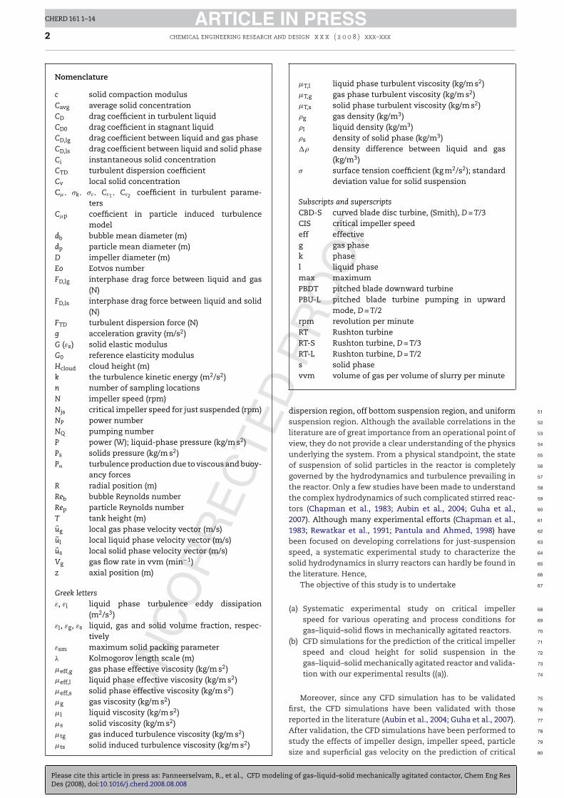
Nomenclature
c solid compaction modulusCavg average solid concentrationCD drag coefficient in turbulent liquidCD0 drag coefficient in stagnant liquidCD,lg drag coefficient between liquid and gas phaseCD,ls drag coefficient between liquid and solid phaseCi instantaneous solid concentrationCTD turbulent dispersion coefficientCv local solid concentrationC�, �k, �ε, Cε1 , Cε2 coefficient in turbulent parame-
tersC�p coefficient in particle induced turbulence
modeldb bubble mean diameter (m)dp particle mean diameter (m)D impeller diameter (m)Eo Eotvos numberFD,lg interphase drag force between liquid and gas
(N)FD,ls interphase drag force between liquid and solid
(N)FTD turbulent dispersion force (N)g acceleration gravity (m/s2)G (εs) solid elastic modulusG0 reference elasticity modulusHcloud cloud height (m)k the turbulence kinetic energy (m2/s2)n number of sampling locationsN impeller speed (rpm)Njs critical impeller speed for just suspended (rpm)NP power numberNQ pumping numberP power (W); liquid-phase pressure (kg/m s2)Ps solids pressure (kg/m s2)P� turbulence production due to viscous and buoy-
ancy forcesR radial position (m)Reb bubble Reynolds numberRep particle Reynolds numberT tank height (m)�ug local gas phase velocity vector (m/s)�ul local liquid phase velocity vector (m/s)�us local solid phase velocity vector (m/s)Vg gas flow rate in vvm (min−1)z axial position (m)
Greek lettersε, εl liquid phase turbulence eddy dissipation
(m2/s3)εl, εg, εs liquid, gas and solid volume fraction, respec-
tivelyεsm maximum solid packing parameter� Kolmogorov length scale (m)�eff,g gas phase effective viscosity (kg/m s2)�eff,l liquid phase effective viscosity (kg/m s2)�eff,s solid phase effective viscosity (kg/m s2)�g gas viscosity (kg/m s2)�l liquid viscosity (kg/m s2)�s solid viscosity (kg/m s2)�tg gas induced turbulence viscosity (kg/m s2)�ts solid induced turbulence viscosity (kg/m s2)
�T,l liquid phase turbulent viscosity (kg/m s2)�T,g gas phase turbulent viscosity (kg/m s2)�T,s solid phase turbulent viscosity (kg/m s2)�g gas density (kg/m3)�l liquid density (kg/m3)�s density of solid phase (kg/m3)�� density difference between liquid and gas
(kg/m3)� surface tension coefficient (kg m2/s2); standard
deviation value for solid suspension
Subscripts and superscriptsCBD-S curved blade disc turbine, (Smith), D = T/3CIS critical impeller speedeff effectiveg gas phasek phasel liquid phasemax maximumPBDT pitched blade downward turbinePBU-L pitched blade turbine pumping in upward
mode, D = T/2rpm revolution per minuteRT Rushton turbineRT-S Rushton turbine, D = T/3RT-L Rushton turbine, D = T/2s solid phasevvm volume of gas per volume of slurry per minute
51
52
53
54
55
56
57
58
59
60
61
62
63
64
65
66
67
68
69
70
71
72
73
74
75
76
77
dispersion region, off bottom suspension region, and uniformsuspension region. Although the available correlations in theliterature are of great importance from an operational point ofview, they do not provide a clear understanding of the physicsunderlying the system. From a physical standpoint, the stateof suspension of solid particles in the reactor is completelygoverned by the hydrodynamics and turbulence prevailing inthe reactor. Only a few studies have been made to understandthe complex hydrodynamics of such complicated stirred reac-tors (Chapman et al., 1983; Aubin et al., 2004; Guha et al.,2007). Although many experimental efforts (Chapman et al.,1983; Rewatkar et al., 1991; Pantula and Ahmed, 1998) havebeen focused on developing correlations for just-suspensionspeed, a systematic experimental study to characterize thesolid hydrodynamics in slurry reactors can hardly be found inthe literature. Hence,
The objective of this study is to undertake
(a) Systematic experimental study on critical impellerspeed for various operating and process conditions forgas–liquid–solid flows in mechanically agitated reactors.
(b) CFD simulations for the prediction of the critical impellerspeed and cloud height for solid suspension in thegas–liquid–solid mechanically agitated reactor and valida-tion with our experimental results ((a)).
Moreover, since any CFD simulation has to be validatedfirst, the CFD simulations have been validated with thosereported in the literature (Aubin et al., 2004; Guha et al., 2007).
CHERD 161 1–14g of gas–liquid–solid mechanically agitated contactor, Chem Eng Res
After validation, the CFD simulations have been performed to 78
study the effects of impeller design, impeller speed, particle 79
size and superficial gas velocity on the prediction of critical 80

ED
PR
OO
F
ARTICLE IN PRESSCHERD 161 1–14
chemical engineering research and design x x x ( 2 0 0 8 ) xxx–xxx 3
has
i81
i82
2
T83
F84
t85
e86
b87
w88
D89
b90
b91
i92
C93
p94
a95
l96
c97
(98
t99
a100
s101
t102
s103
104
105
106
107
The experiments were carried out with different impeller 108
types and different impeller speeds to determine the quality of 109
UN
CO
RR
EC
TFig. 1 – Flow regime and gas holdup in three-p
mpeller speed and cloud height for just suspended conditionn gas–liquid–solid mechanically agitated reactor.
. Experimental details
he schematic diagram of experimental setup is shown inig. 2. Experiments were conducted in a baffled cylindricalank of internal diameter, T of 250 mm and which is transpar-nt to light so that the suspension of solids is easily visible. Theottom of the tank is elliptical in shape. Two types of impellersere employed viz., six-bladed Rushton turbine of diameter= 100 mm (D = T/2.5) and four-bladed 45◦ pitched blade tur-
ine of diameter D = 125 mm (D = T/2) with the impeller offottom clearance C = 62.5 mm (C = T/4). The dimensions of the
mpellers chosen for this work are based on the observation ofhapman et al. (1983) and Pantula and Ahmed (1998) that theerformance in terms of suspension quality at higher gas ratesre much improved if larger diameter is employed. Similarlyow clearance has been shown to enhance particle suspensionapability (Nienow, 1968). For this experimental study, water� = 1000 kg/m3) is used as the liquid phase and ilmenite par-icles � = 4200 kg/m3 in the size range of 150–230 �m is useds solid phase. Air is admitted to the reactor using a pipe
Please cite this article in press as: Panneerselvam, R., et al., CFD modelinDes (2008), doi:10.1016/j.cherd.2008.08.008
parger and is placed at a clearance of 25 mm from the cen-er of the impeller. Agitation was carried out using a variablepeed DC motor and the speed of agitation was noted using a
e agitated reactor (Pantula and Ahmed, 1998).
tachometer. Power consumptions were computed using mea-sured values of current and voltages. Other details of thepresent experiment study are available in our earlier publishedwork (Geetha and Surender, 1997).
CHERD 161 1–14g of gas–liquid–solid mechanically agitated contactor, Chem Eng Res
Fig. 2 – Experiment setup used for this study.

ED
ARTICLE IN PRESSCHERD 161 1–14
4 chemical engineering research and d
Fig. 3 – Prediction of critical impeller speed from graphical
110
111
112
113
114
115
116
117
118
119
120
121
122
123
124
125
126
127
128
129
130
131
132
133
134
135
136
137
138
139
140
141
142
143
144
145
146
147
148
149
150
151
152
153
154
155
156
157
158
159
160
161
162
163
164
165
166
167
168
169
170
171
172
173
174
175
176
177
178
179
180
181
182
183
ORRE
CT
plot of NRe vs. NP.
solid suspension. The critical impeller speed of solid suspen-sion was determined experimentally for four different solidloading rates viz., 10, 20, 30 and 40 wt.%. The critical impellerspeed for solid suspension is predicted by observing visuallythat the solids remain at the tank bottom for not more than2 s (Zwietering, 1956). Since visual method is reported to benot very accurate for higher solid loading rates, an alternatemethod on the measurement of variation in impeller powerconsumption with respect to the impeller speed was also usedto determine the critical impeller speed. The same methodwas adapted by Rewatkar et al. (1991) for determination ofNjs and Njsg for their reactors where the diameter of tankwas ranging from 0.57 to 1.5 m. In this method, the graph ofpower number versus Reynolds number is plotted. Then theminimum value of the curve is taken as the critical impellerspeed. This is shown in Fig. 3 and the value obtained for criti-cal impeller speed by visual method, is also shown in Table 1.The error percentage was calculated as
Error % =(
CISvisual − CISgraphical
CISvisual
)× 100
It can be observed that the percentage of error is in therange of 3–6% for various operating conditions. Since the devi-ation is not much between both the approaches and visualmethod is much more easier, this method is used for deter-mination of critical impeller speed for further experimentalconditions.
3. CFD modeling
In the literature, CFD based simulations have been carriedout for the hydrodynamics of liquid–solid flows in agitatedreactors by Bakker et al. (1994), Micale et al. (2000), Sha etal. (2001), Barrue et al. (2001), Kee and Tan (2002), Montante
UN
C
Please cite this article in press as: Panneerselvam, R., et al., CFD modelinDes (2008), doi:10.1016/j.cherd.2008.08.008
and Magelli (2005), Khopkar et al. (2006a,b) and by Gosmanet al. (1992), Bakker and van den Akker (1994), Lane et al.(2005), Khopkar et al. (2006a,b) for gas–liquid flows in agitated
Table 1 – Values of critical impeller speed
Particle size (�m) Air flow rate (vvm)
Visua
23000.51.0
PR
OO
F
esign x x x ( 2 0 0 8 ) xxx–xxx
reactors by employing Eulerian–Eulerian approach. But for thecase of gas–liquid–solid flows in mechanically agitated reac-tors, available literature is less except the most recent work ofMurthy et al. (2007) and also experimental data for the localflow characteristics like phase velocities and holdup profileare also not available for the validation of CFD models. This isbecause of complexities involves in three phase flows.
Also during the last few decades, various approaches havebeen proposed in the literature for the prediction of flow pat-tern induced by the revolving impeller in stationary tanks. Themost widely used approach in the literature is the multipleframe of reference (MFR) approach in which the tank is dividedin two regions, i.e., a rotating frame which encompasses theimpeller and the flow surrounding it and a stationary framewhich includes the tank, baffles and the flow outside theimpeller frame. The boundary between the inner and outerregion need to be selected in such a way that, the predictedresults are not sensitive to its actual location. The otherapproach is sliding grid approach, in which inner region isrotated during computation and slide along the interface withouter region. This method is fully transient and is consideredas more accurate, but it is requires more computational timewhen compared to MFR.
In this study, the hydrodynamics of gas–liquid–solid flowsin mechanically agitated contactor is simulated using Eule-rian–Eulerian multi-fluid multiphase flow model. A MFR isused to model the impeller and tank region. Each phaseis treated as different continua which interacts with otherphases everywhere in the computational domain. The motionof each phase is governed by respective mass and momentumconservation equations. The pressure field is assumed to bethe shared by all the three phases according to their volumefraction. The governing equations are given below.
• Continuity equations for k = (g, l, s)
∂
∂t(εk · �k) + ∇ · (�k · εk · �uk) = 0 (1)
• Momentum equations◦ Gas phase (dispersed fluid phase)
∂
∂t(�g · εg · �ug) + ∇ · (�g · εg · �ug�ug)
= −εg · ∇P + ∇ · (εg�eff,g(∇�ug + (∇�ug)T)) + �g · εg · g − FD,lg
(2)
◦ Liquid phase (continuous phase)
∂
∂t(�l · εl · �ul) + ∇ · (�l · εl · �ul�ul)
CHERD 161 1–14g of gas–liquid–solid mechanically agitated contactor, Chem Eng Res
= −εl · ∇P + ∇ · (εl�eff,l(∇�ul + (∇�ul)T)) 184
+�l · εl · g + FD,lg + FD,ls (3) 185
Critical impeller speed (rpm) % of Error
l method Graphical method
330 315 4.5428 415 3.0529 559 5.6

D
ARTICLE IN PRESSCHERD 161 1–14
nd d
186
187
188
189
w190
e191
t192
c193
(194
3195
T196
l197
e198
t199
t200
i201
t202
t203
s204
d205
p206
s207
f208
t209
o210
t211
d212
213
s214
F215
w216
u217
218
w219
s220
g221
C222
223
s224
F225
w226
o227
m228
d229
230
231
232
233
234
235
236
237
238
239
240
241
242
243
244
245
246
247
248
249
250
251
252
253
254
255
256
257
258
259
260
261
262
263
264
265
266
267
268
269
UN
CO
RR
EC
TE
chemical engineering research a
◦ Solid phase (dispersed solid phase)
∂
∂t(�s · εs · �us) + ∇ · (�s · εs · �us�us)
= −εs · ∇P − ∇Ps + ∇ · (εs�eff,s(∇�us
+(∇�us)T)) + �s · εs · g − FD,ls (4)
here P is pressure, which is shared by all fluids. �eff is theffective viscosity. The second term in solid phase momen-um Eq. (4) accounts for additional solids pressure due to solidollision and last term (FD) in all the momentum equations2)–(4) represents the interphase drag force term.
.1. Interphase momentum transfer
here are various interchange forces such as the drag, theift force and the added mass force, etc. during momentumxchange between the different phases. But the main interac-ion force is due to the drag forced caused by the slip betweenhe different phases. Recently Khopkar et al. (2003, 2005) stud-ed the influence of different interphase forces and reportedhat the effect of the virtual mass force is not significant inhe bulk region of stirred vessel and the magnitude of the Bas-et force is also much smaller than that of the inter-phaserag force. Further they also have reported that turbulent dis-ersion terms are significant only in the impeller dischargetream. Similarly Ljungqvist and Rasmuson (2001) have alsoound very little influence of the virtual mass and lift force onhe simulated solid holdup profiles. Hence based on their rec-mmendations and also to reduce computational time, onlyhe inter-phase drag force and non-drag force of turbulentispersion is considered in the present simulation.
The drag force between liquid and solid phases is repre-ented by the following equation
D,ls = CD,ls34
�1εs
dp|�us − �u1|(�us − �u1) (5)
here the drag coefficient proposed by Brucato et al. (1998) issed which is as follows
CD,ls − CD0
CD0= 8.67 × 10⁻⁴
(dp
�
)3
(6)
here dp is the particle size and � is the Kolmogorov lengthcale, CD0 is the drag coefficient in stagnant liquid which isiven as
D0 = 24Re
(1 + 0.15Re0.687p ) (7)
The drag force between the gas and liquid phases is repre-ented by the equation
D,lg = CD,lg34
�lεg
db|�ug − �ul|(�ug − �ul) (8)
here the drag coefficient exerted by the dispersed gas phasen the liquid phase is obtained by the modified Brocade dragodel (Khopkar et al., 2006a,b), which accounts for interphase
rag by microscale turbulence and is given by
Please cite this article in press as: Panneerselvam, R., et al., CFD modelinDes (2008), doi:10.1016/j.cherd.2008.08.008
CD,lg − CD
CD= 6.5 × 10⁻⁶
(dp
�
)3
(9)
PR
OO
F
esign x x x ( 2 0 0 8 ) xxx–xxx 5
where CD is the drag coefficient of single bubble in stagnantliquid and is given by
CD0 = Max(
24Reb
(1 + 0.15Re0.687b ),
83
Eo
Eo + 4
)(10)
where Eo is Eotvos number, Reb is the bubble Reynolds numberand is given by
Reb = |�ul − �ug|db
l(11)
Eo = g(�l − �g)d2b
�(12)
3.2. Turbulent dispersion force
The turbulent dispersion force is the result of the turbulentfluctuations of liquid velocity. It approximates a diffusionof the gas phase from higher fraction region to lower frac-tion region by turbulent fluctuations of liquid velocity. Theimportance of modeling of turbulent dispersion in liquid–solidstirred tank is also highlighted in literature (Ljungqvist andRasmuson, 2001; Barrue et al., 2001). The following equa-tion for the turbulent dispersion force derived by Lopez deBertodano (1992) is used for the present simulation and isgiven by
FTD = −CTD�lkl∇εl (13)
where CTD is a turbulent dispersion coefficient and the recom-mended value for turbulent dispersion coefficient CTD is in therange of 0.1–1.0. But in literature (Cheung et al., 2007; Lucas etal., 2007) the most widely used value for turbulent dispersioncoefficient is 0.1. Hence for the present investigation this valueis used.
3.3. Constitutive equations for turbulence
The standard k – ε model for single phase flows has beenextended for the three phase flows for simulating the tur-bulence in the present study. The corresponding values of kand ε are obtained by solving the transport equations for theturbulence kinetic energy and turbulence dissipation rate.
∂(εl�lk�)∂t
+∇ ·(
εl
(�l
−→ul kl−(
�+�tl
�k
)�kl
))=εl(Pl − �lεl) (14)
∂(εl�lεl)∂t
+ ∇ ·(
εl�l−→ul εl −
(� + �tl
�ε
)�εl
)
= εlεl
kl(Cε1 Pl − Cε2 �lεl) (15)
where Cε1 = 1.44, Cε2 = 1.92, �k = 1.0, �ε = 1.3 and Pl, the turbu-lence production due to viscous and buoyancy forces is givenby
Pl = �tl∇�u · (∇�u + ∇�uT) − 23
∇ · �u(3�tl∇ · �u + �lkl) (16)
CHERD 161 1–14g of gas–liquid–solid mechanically agitated contactor, Chem Eng Res
For liquid phase effective viscosity is calculated as 270
�eff,l = �l + �T,l + �tg + �ts (17) 271

ED
ARTICLE IN PRESSCHERD 161 1–14
6 chemical engineering research and design x x x ( 2 0 0 8 ) xxx–xxx
Table 2 – Tank design parameters and physical properties
Reference Impeller type Geometry Properties Operatingconditions
Guha et al. (2007) 6-DTT = H = 0.2 m Liquid: � = 1000 kg/m3
Njs = 1200 rpmD/T = 1/3, C/T = 1/3 Solid: � = 2500 kg/m3,
dp = 300 �m
Spidla et al. (2005) 6-PBTDT = H = 1.0 m Liquid: � = 1000 kg/m3
Njs = 267 rpmD/T = 1/3, C/T = 1/3 Solid: � = 2500 kg/m3,
dp = 350 �m
Aubin et al. (2004) 6-PBTD and 6-PBTUT = H = 0.19 m, C = T/3 Liquid:
� = 1000 kg/m3,Gas:Air
N = 300 rpmD = T/3
Our experiment 6-DT and 4-PBTDT = H = 0.25 m Liquid: � = 1000 kg/m3
Njs = 330–520 rpmFor DT, D = 0.1 m, ForPBTD, D = 0.12 m
5 m
Solid: � = 4200 kg/m3,dp = 125, 180, and
272
273
274
275
276
277
278
279
280
281
282
283
284
285
286
287
288
289
290
291
292
293
294
295
296
297
298
299
300
301
302
303
304
305
306
307
308
RECT
C/T = 0.062
where �l is the liquid viscosity and �T,l is the liquid phaseturbulence viscosity or shear induced eddy viscosity, which iscalculated based on the k − ε model as
�Tl = c��lk2
ε(18)
�tg, �ts represents the gas and solid phase induced turbulenceviscosity respectively and are given by Sato et al. (1981)
�tg = c�p�sεsds|�ug − �ul| (19)
�ts = c�p�sεsds|�us − �ul| (20)
For gas and solid phases the respective effective viscositiesare calculated as
�eff,g = �g + �T,g (21)
�eff,s = �s + �T,s (22)
The turbulence viscosity of gas and solid phases are calcu-lated from the turbulence viscosity of liquid phase using thezero equation model:
�T,g = �g
�l�T,l (23)
UN
CO
R
Please cite this article in press as: Panneerselvam, R., et al., CFD modelinDes (2008), doi:10.1016/j.cherd.2008.08.008
�T,s = �s
�l�T,l (24)
Fig. 4 – Computational grid of stirred tank used in th
PR
OO
F230 �m; Gas:Air
3.4. Solid pressure closure term
The solid pressure due to the particle–particle interactionforce is based on a concept of elasticity, which is describedas a function of local voidage. The most popular constitutiveequation for solid pressure is
∇Ps = G(εs)∇εs (25)
where G(εs) is the elasticity modulus and it is given as
G(εs) = G0 exp(c(εs − εsm)) (26)
as proposed by Bouillard et al. (1989), where G0 is the referenceelasticity modulus, c the compaction modulus and εsm is themaximum packing parameter.
4. Numerical methodology
The commercial code ANSYS CFX-11 is used for thehydrodynamic simulation of gas–liquid–solid flows in themechanically agitated reactor. The details of the reactor geom-etry and the operating parameters are given in Table 2. Dueto the symmetry of geometry, only one-half of the agitatoris considered as the computational domain. The first step inCFD simulation is to discretize the computational domain. Inthis study the geometry is discretized using block-structuredgrids which allows finer grids in regions where higher spatial
CHERD 161 1–14g of gas–liquid–solid mechanically agitated contactor, Chem Eng Res
resolutions are required. The blocks are further divided into 309
finer grids using the structured hexa mesh option of ICEM so 310
that total number of computational nodes is around 2,00,000. 311
is study: (a) tank; (b) Rushton Turbine; (c) PBTD.

D P
R
ARTICLE IN PRESSCHERD 161 1–14
nd d
F312
l313
s314
c315
i316
f317
b318
w319
T320
r321
w322
d323
d324
t325
a326
e327
s328
(329
a330
m331
r332
s333
b334
e335
4336
o337
c338
l339
l340
T341
c342
d343
344
H345
346
e347
a348
o349
o350
d351
v352
T353
p354
s355
a356
s357
d358
c359
c360
w361
p362
5
T363
t364
(365
366
367
( 368
369
370
371
372
373
374
375
376
377
378
379
380
381
382
383
384
385
386
387
388
389
390
tion for experimental data of Guha et al. (2007) for the case of 391
radial type impeller and Spidla et al. (2005) for case of axial 392
UN
CO
RR
EC
TE
chemical engineering research a
ig. 4 depicts a typical mesh used for the numerical simu-ation in this work. A MFR approach has been used for theimulation of impeller the impeller rotation. In this method,omputational domain is divided into impeller zone (rotat-ng reference frame) and stationary zone (stationary referencerame). The interaction of inner and outer regions is accountedy suitable coupling at the interface between the two regionshere the continuity of the absolute velocity is implemented.he boundary between inner and outer region was located at/R = 0.6. No-slip boundary conditions are applied on the tankalls and shaft. The free surface of tank is considered as theegassing boundary condition. Initially the solid particles areistributed in a homogenous way inside the whole computa-ional domain. The bubble size distribution in mechanicallygitated reactor depends on the design and operating param-ters and there is no experimental data available for bubbleize distribution. It has been reported by Barigou and Greaves1992) that their bubble size distribution is in the range of 3.5nd 4.5 mm for the higher gas flow rates used in their experi-ents. Also In the recent simulation on gas–liquid stirred tank
eactor carried out by Khopkar et al. (2003) a single bubbleize of 4 mm was assumed based on the bubble size distri-ution of this author. Since the gas flow rates used in ourxperiments are also in the same range, a mean bubble size ofmm is assumed for all our simulations. Further, the validityf bubble size used in the CFD simulation is rechecked by cal-ulating the bubble size based on the reported correlations initerature (Calderbank and Moo-Young, 1961) using the simu-ation results of gas holdup and power consumption values.he mean bubble size is calculated according to the followingorrelation
b = 4.15
((�ε)0.4�0.2
�0.6
)−1
ε0.5g + 0.0009 (27)
The value obtained for mean bubble size is around 3.7 mm.ence for further simulations, the bubble size of 4 mm is used.
The discrete algebraic governing equations are obtained bylement-based finite volume method. The second order equiv-lent to high-resolution discretization scheme is applied forbtaining algebraic equations for momentum, volume fractionf individual phases, turbulent kinetic theory and turbulenceissipation rate because of accuracy and stability. Pressureelocity coupling is achieved by the Rhie Chow algorithm.he governing equations are solved using the advanced cou-led multi-grid solver technology of ANSYS CFX-11. Steadytate simulations are performed for different types of impeller,gitation speeds, particle diameter, solid concentration anduperficial gas velocity. The simulation started with the fullyeveloped single-phase flow field in order to enhance theonvergence of multiphase flow simulation. The convergenceriteria used in all simulations is 10−4 which is the factor byhich the initial mass flow residual reduces as the simulationrogresses.
. Results and discussions
he validity of the CFD simulation is carried out initially forhe following two cases to confirm the validity of the model:
a) Prediction of axial, radial and tangential solid velocity
Please cite this article in press as: Panneerselvam, R., et al., CFD modelinDes (2008), doi:10.1016/j.cherd.2008.08.008
components along axial and radial directions for thecase of liquid–solid agitated contactor with a radial typeimpeller (RT).
OO
F
esign x x x ( 2 0 0 8 ) xxx–xxx 7
b) Prediction of axial solid distribution for the case of liq-uid–solid agitated contactor with an axial type impeller(PBTD).
(c) Prediction of axial liquid velocity component along theradial direction for gas–liquid agitated contactor with axialtype impeller (PBTD and PBTU).
5.1. Two-phase flows: solid–liquid flows inmechanically agitated contactor
Hydrodynamic simulations of liquid–solid agitated reactor arecarried and the results obtained are validated with experi-mental results of Guha et al. (2007). For the case of radialtype impeller, Guha et al. (2007) characterized the solidhydrodynamics in a solid–liquid stirred tank reactor usingcomputer-automated radioactive particle tracking (CARPT)and measured axial and radial distribution of solid axial veloc-ity for overall solid holdup of 7% at impeller speed of 1200 rpmat the radial location of r/R = 0.5. Similarly for the case of axialtype impeller, experimental data of Spidla et al. (2005) havebeen used for the comparison of the axial solid distributions.They have presented detailed particle distribution data usinga conductivity probe for a pilot plant stirred vessel of diame-ter 1 m which is stirred with six pitched blade turbine. Fig. 5shows the solid velocity pattern obtained from CFD simula-
CHERD 161 1–14g of gas–liquid–solid mechanically agitated contactor, Chem Eng Res
Fig. 5 – Solid flow pattern for the case of: (a) Rushtonturbine; (b) PBTD impeller.

EC
TED
PR
O
ARTICLE IN PRESSCHERD 161 1–14
8 chemical engineering research and d
Fig. 6 – Axial profiles of various components of solidvelocity for an overall solid holdup of 7% at 1200 rpm: (a)radial component of solids velocity; (b) tangentialcomponent of solids velocity; (c) axial component of solids
393
394
395
396
397
398
399
400
401
402
403
404
405
406
407
408
409
410
411
412
413
414
415
416
417
418
419
420
421
422
423
424
425
426
427
428
429
430
Fig. 8 shows that the comparison between numerical and 431
experimental results for non dimensional axial distribution of 432
Fig. 7 – Radial profiles of various components of solidvelocity for overall solid holdup of 7% at 1200 rpm: (a) radial
UN
CO
RRvelocity.
type impeller in a liquid–solid stirred tank reactor. Fig. 5(a)shows that for the case of Rushton type impeller, there existstwo circular loops above and below the impeller and a radialjet of solids flow in the impeller stream. For the case of PBTDimpeller (Fig. 5(b)), there is a single circulation loop for solidsand the solids move upward towards the surface of liquid andturn down to bottom. It can be seen that the flow pattern pre-dicted by CFD simulations quantitatively agrees with profileavailable in literature.
The variation of non-dimensional solid velocity compo-nents of axial, radial and tangential (U/Utip, where Utip = DN)along non-dimensional axial directions (z/T) are plotted inFig. 6(a–c) for the case of Ruston type impeller at a radial posi-tion of r/R = 0.5. The overall solid holdup is 7% at the criticalimpeller speed of 1200 rpm. The experimental data plotted inFig. 6(a–c) corresponds to the data given by Guha et al. (2007).
Please cite this article in press as: Panneerselvam, R., et al., CFD modelinDes (2008), doi:10.1016/j.cherd.2008.08.008
It can be observed that the axial variation of the axialcomponent of solid velocity agrees well with the experimen-
OF
esign x x x ( 2 0 0 8 ) xxx–xxx
tal results. But for the other two components, even thoughthere is a quantitative agreement between experimental andsimulation results, there is a discrepancy between numericalsimulations and experimental results qualitatively near theimpeller region. This may be due to the fact that the meanvelocity components of fluid mainly depend on the turbu-lent fluctuations and these turbulent fluctuations dominatesmainly at the impeller region of stirred tank and the tur-bulence model used in present study is not able to captureproperly the strong turbulence near the impeller region.
Similarly non-dimensional radial profiles ((r − Ri)/(R − Ri),where Ri is the impeller radius) of various components of non-dimensional solid velocity at the axial position of z/T = 0.34is shown in Fig. 7. The same trend is observed in this casealso. This type of discrepancy is confirmed by Guha et al.(2008) where they have carried out Large Eddy Simulation andEuler–Euler simulation of solid suspension in stirred tank reac-tor and concluded that there are major discrepancies in theprediction of solid velocities by both the numerical methodsnear the impeller region.
CHERD 161 1–14g of gas–liquid–solid mechanically agitated contactor, Chem Eng Res
component of solids velocity; (b) tangential component ofsolids velocity; (c) axial component of solids velocity.

D
ARTICLE IN PRESSCHERD 161 1–14
chemical engineering research and d
Fig. 8 – Normalized axial solid concentration profiles at acritical impeller speed of Njs = 267 rpm with 10vol.% solidh
s433
f434
o435
t436
5437
m438
F439
m440
v441
t442
p443
p444
p445
i446
p447
s448
449
450
451
452
453
454
455
456
457
458
459
460
461
462
463
464
465
466
467
468
469
470
471
Table 3. It can be observed that the values predicted by CFD 472
Fa
old up for PBDT impeller.
olid volume fraction (Cv/Cavg) at the radial position of r/R = 0.8or an overall solid holdup of 10% at the critical impeller speedf 267 rpm for the case of PBTD impeller and it can be observedhat the comparison is quite good.
.2. Two-phase flows: gas–liquid flows inechanically agitated contactor
or the case of gas–liquid flows in an agitated contactor, CFDodel predictions of radial profiles of axial liquid velocity are
alidated with the experimental data of Aubin et al. (2004) forhe pitched blade turbine with downward (PBTD) and upwardumping (PBTU). For the case of pitched blade downwardsumping, the radial profile of the nondimensional axial com-onent of liquid velocity (Uz/Utip) is shown in Fig. 9 at the
mpeller speed of 300 rpm. The values are plotted at four axial
UN
CO
RR
EC
TE
Please cite this article in press as: Panneerselvam, R., et al., CFD modelinDes (2008), doi:10.1016/j.cherd.2008.08.008
ositions (z/T = 0.19, 0.31, 0.49 and 0.65). Similar results arehown in Fig. 10 for the case of pitched blade upwards pump-
ig. 9 – Radial profiles of dimensionless axial liquid velocity at vnd downward pumping.
PR
OO
F
esign x x x ( 2 0 0 8 ) xxx–xxx 9
ing where the impeller speed is taken as 300 rpm. It can be seenclearly that there exists excellent agreement between the CFDsimulations and experimental data.
5.3. Gross flow field characteristics
The gross flow field characteristics of mechanically agi-tated reactor are generally characterized by power number,pumping number and pumping efficiency. Since the overallprediction of CFD is good, CFD simulation is used further tocalculate these values. The pumping number (NQ) and powernumber (NP) are calculated as follows
NQ = 2∫
rU dr
ND3(28)
The limits of integration for the radial distance are from thesurface of the shaft to the impeller radius and U is the axialliquid velocity
NP = P
�N3D5(29)
The pumping efficiency is then calculated by the followingequation
Pumping efficiency = NQ
NP(30)
The Power draw (P) is determined from torque equation(P = 2NT) and total torque can be calculated from the torqueacting on the all the blades.
The predicted values of pumping number and power num-ber are compared with experimental data and are shown in
CHERD 161 1–14g of gas–liquid–solid mechanically agitated contactor, Chem Eng Res
simulations agrees reasonably well with the experimental val- 473
ues but the overall gas holdup predicted by CFD simulation 474
arious axial locations for the case of pitched blade turbine

ED
RO
OF
ARTICLE IN PRESSCHERD 161 1–14
10 chemical engineering research and design x x x ( 2 0 0 8 ) xxx–xxx
y at
475
476
477
478
479
480
481
482
483
484
485
486
487
488
489
490
491
492
493
494
495
496
497
498
499
500
501
502
503
504
505
506
507
508
509
RREC
T
Fig. 10 – Radial profiles of dimensionless axial liquid velocitand upward pumping.
is slightly varies with the experimental values. This may bebecause the gas holdup mainly depends on the bubble sizedistribution, which is not included in the present study.
5.4. Three phase flows: gas–liquid–solid flows in anagitated contactor
In this section, CFD simulation has been used for simulatingthe hydrodynamics of gas–liquid–solid flows in an agitatedcontactor. For the case of three phase systems, experimen-tal data for gas and solid hold-up profile are very limitedor not available. Therefore, the present simulations havebeen focused on prediction of the bulk flow properties ofgas–liquid–solid mechanically agitated contactor such as crit-ical impeller speed. The values obtained by CFD simulationfor critical impeller speed is compared with our experimentaldata (Section 2).
5.4.1. Solid suspension studiesCFD simulation of three phase stirred dispersion is undertaken
UN
CO
Please cite this article in press as: Panneerselvam, R., et al., CFD modelinDes (2008), doi:10.1016/j.cherd.2008.08.008
in this study to verify quantitatively the solid suspension char-acteristics at the critical impeller speed which was obtainedby our experiments. The quality of solid suspension is eval-
Table 3 – Gross characteristics of gas–liquid stirred vessel
Operatingcondition
Total gas holdup Power number (NP)
Experiment(Aubin et al., 2004)
CFD Experiment(Aubin et al., 2004)
CFD
PBTDN = 300 rpm
0.037 0.042 1.56 1.3
PBTUN = 300 rpm
0.058 0.052 1.80 1.5
Pvarious axial locations for the case of pitched blade turbine
uated by the extent of off-bottom suspension, i.e., criticalimpeller speed for just suspended state and extent of axialsolid distribution, i.e., solid suspension height. Generally Zwi-etering criteria (the impeller speed at which the particles donot remain stationary at the bottom of the vessel) is usedfor characterizing the off bottom suspension. But incorpo-rating Zwietering criteria is difficult in the Eulerian–Eulerianapproach of the present CFD simulation. Hence the methodproposed by Bohnet and Niesmak (1980) which is based on thevalue of standard deviation is used in the present study for theprediction of critical impeller speed. This standard deviationmethod was also successfully employed for liquid–solid sus-pension by various authors (Khopkar et al., 2006a,b; Murthy etal., 2007). It is defined as
� =
√√√√1n
n∑i=1
(Ci
Cavg− 1
)2
(31)
CHERD 161 1–14g of gas–liquid–solid mechanically agitated contactor, Chem Eng Res
where n is the number of sampling locations used for mea- 510
suring the solid holdup. The increase in the homogenization 511
(better suspension quality) is manifested as the reduction of 512
Pumping number (NQ) Pumping efficiency (NQ/NP)
Experiment(Sardeing et al.,
2004)
CFD Experiment CFD
0.59 0.64 0.39 0.49
0.57 0.49 0.32 0.33

D P
RO
OF
ARTICLE IN PRESSCHERD 161 1–14
nd design x x x ( 2 0 0 8 ) xxx–xxx 11
t513
i514
s515
s516
c517
i518
(519
t520
s521
o522
i523
s524
s525
5526
t527
b528
t529
b530
t531
a532
e533
p534
a535
t536
F537
fi538
b539
h540
t541
t542
r543
d544
f545
h546
p547
H548
v549
5550
l551
s552
d553
i554
i555
i556
C557
i558
o559
t560
s561
o562
i563
o564
t565
Fig. 11 – Solid holdup distribution predicted by CFD for thesolid hold up of 30 wt.%, particle diameter of 230 �m and agas flow rate of 0.5 vvm at the critical impeller speed: (a)Rushton turbine impeller; (b) PBTD impeller.
Table 5 – Effect of particle size on quality of suspension
Particlediameter (�m)
Njs (rpm) Standarddeviation (�)
Cloud height(Hcloud/H)
RT125 340 0.72 0.90180 375 0.50 0.88230 520 0.80 0.92
PBTD125 325 0.36 0.82180 346 0.56 0.88
OR
RE
CTE
chemical engineering research a
he standard deviation value. The range of standard deviations broadly divided into three ranges based on the quality ofuspension. � < 0.2 for uniform suspension, 0.2 < � < 0.8 for justuspension, and � > 0.8 for incomplete suspension. Anotherriteria that has been used to quantify solid suspensions based on the solid suspension height, i.e., cloud heightHcloud = 0.9H). Kraume (1992) used these criteria to evaluatehe critical impeller speed in liquid–solid suspension. CFDimulations were carried out for various impellers and vari-us gas flow rates to evaluate the quality of solid suspension
n three phase stirred suspensions in this study. The impellerpeed was set equivalent to the value of the critical impellerpeed which was obtained by our experiments.
.4.1.1. Effect of impeller design on solid suspension. To studyhe effect of various types of impellers, CFD simulations haveeen carried out for three types of impellers viz., Rushtonurbine impeller with the impeller speed of 520 rpm, four-laded pitched blade turbine with downward pumping withhe impeller speed of 428 rpm. The impeller chosen is equiv-lent to the critical impeller speed value obtained by ourxperiments for the following operating conditions. The solidarticle size chosen is 230 �m, with solid loading of 30 wt.% atn air sparging rate of 0.5 vvm. Fig. 11 shows solid volume frac-ion profiles predicted by CFD simulation at midbaffle plane.urther, the predicted dimensionless axial concentration pro-les are also shown in Fig. 12. The quality of suspension haseen verified by both standard deviation approach and cloudeight method. The standard deviation was calculated usinghe values of the solid volume fraction stored at all computa-ional cells. The value of the standard deviation values withespect to the impeller rotational speed and cloud height forifferent type of impellers is shown in Table 4. It can be seenrom the table that both standard deviation values and cloudeight values obtained by CFD simulation shows the just sus-ended condition for solids for both the type of impellers.ence the critical impeller speed observed by experiments isalidated by the present CFD simulation.
.4.1.2. Effect of particle size on solid suspension. CFD simu-ations have been carried out to study the effect of particleize on the critical impeller speed for three phase stirredispersions. Three particle sizes are chosen for the present
nvestigation, viz., 125, 180 and 230 �m. Both types ofmpellers, viz., Rushton and PBTD are chosen for the presentnvestigation. Solid volume fraction distribution obtained byFD simulation at the critical impeller speed condition for var-
ous particle sizes are shown in Fig. 13 for the solid loadingf 30 wt.% and an air flow rate of 0.5 vvm. From CFD simula-ion, the standard deviation and cloud height of suspendedolid are also obtained and they are shown in Table 5. It can bebserved that the critical impeller speed for solid suspension
UN
C
Please cite this article in press as: Panneerselvam, R., et al., CFD modelinDes (2008), doi:10.1016/j.cherd.2008.08.008
ncreases with an increase in the particle size for fixed set ofperating conditions and impeller configuration. This is dueo the fact that, with increase in the particle size, the settling
Table 4 – Effect of impeller type on quality of suspension
Type ofimpeller
Njs (rpm) Standarddeviation (�)
Cloud height(Hcloud/H)
RT 520 0.80 0.92PBTD 428 0.51 0.87
566
567
568
569
570
571
572
230 428 0.51 0.87
velocity increases which leads to more energy requirement forsuspension.
5.4.1.3. Effect of air flow rate on solid suspension. CFD simula-tions have been carried out to study the effect of gas superficialvelocity on the critical impeller speed. Fig. 14 shows solidvolume fraction distribution predicted by CFD at the criticalimpeller speed for the solid loading of 30 wt.% and particle size
CHERD 161 1–14g of gas–liquid–solid mechanically agitated contactor, Chem Eng Res
of 230 �m with different air flow rates (Vg = 0, 0.5 and 1.0 vvm). 573
The values of the standard deviation values and cloud height 574

ED
PR
OO
F
ARTICLE IN PRESSCHERD 161 1–14
12 chemical engineering research and design x x x ( 2 0 0 8 ) xxx–xxx
Fig. 12 – Axial solid holdup profile predicted by CFD for thesolid hold up of 30 wt.%, particle diameter of 230 �m and agas flow rate of 0.5 vvm at the critical impeller speed: (a)
575
576
577
578
579
580
581
582
583
584
585
586
587
RR
EC
TRushton turbine impeller; (b) PBTD impeller.
with respect to the impeller speed for different gas flow rateswith different type of impellers are shown in Table 6. The tablevalues clearly show that the critical impeller obtained by ourexperiments agrees with CFD simulation in terms of standarddeviation value and cloud height. It can be shown from Table 6that the critical impeller speed for solid suspension increaseswith an increase in the air flow rate for fixed set of operat-ing conditions and different impeller configuration. Generallywhen gas is introduced in a suspended medium, there will be areduction in quality of suspension and solid cloud height dueto decrease in impeller pumping capacity. This is due to for-
UN
CO
Please cite this article in press as: Panneerselvam, R., et al., CFD modelinDes (2008), doi:10.1016/j.cherd.2008.08.008
mation of gas cavities behind the impeller blade and decreasein liquid turbulence and circulation velocity. Hence there is
Table 6 – Effect air flow rate on quality of suspension
Air flow rate(vvm)
Njs (rpm) Standarddeviation (�)
Cloud height(Hcloud/H)
RT0 370 0.78 0.80.5 520 0.80 0.921.0 612 0.61 1.0
PBTD0 330 0.8 0.810.5 428 0.51 0.871.0 529 0.59 0.91
Fig. 13 – Effect of particle size on solid concentrationdistribution for Rushton Turbine by CFD simulations(� = 4200 kg/m3, 30 wt.%) at the critical impeller speed: (a)
588
589
590
591
125 �m; (b) 180 �m; (c) 230 �m.
need to increase the power for achieving the suspension. Theeffect of air flow rate on critical impeller speed depends uponthe type of impeller used because the reduction in power withincreasing gas flow rate varies with type of impeller (Rewatkar
CHERD 161 1–14g of gas–liquid–solid mechanically agitated contactor, Chem Eng Res
et al., 1991). From Table 6, it can also be seen that for a par- 592
ticular gas flow rate, the critical impeller speed for Rushton 593
turbine impeller (RT) is more compared to the critical impeller 594

NC
OR
RE
CTE
D
ARTICLE IN PRESSCHERD 161 1–14
chemical engineering research and de
Fig. 14 – Effect of air flow rate on solid concentrationdistribution for Rushton Turbine by CFD simulations(dp = 230 �m, � = 4200 kg/m3, 30 wt.%) at the critical impellerspeed: (a) 0; (b) 0.5 vvm; (c) 1.0 vvm.
s595
i596
H597
i598
aQ2
599
600
601
602
603
604
605
606
607
608
609
610
611
612
613
614
615
Q3
616
617
618
619
620
621
622
623
624
625
626
627
628
629
630
631
632
633
634
635
636
637
638
639
640
641
642
643
644
645
646
647
648
649
650
651
652
U
peed of Pitched blade turbine (PBTD). This is because theres reduction in power consumption for PBTD compared to RT.
Please cite this article in press as: Panneerselvam, R., et al., CFD modelinDes (2008), doi:10.1016/j.cherd.2008.08.008
ence PBTD is still efficient than RT when gas is introducednto the solid–liquid suspension. The same observation waslso reported by Murthy et al. (2008).
653
PR
OO
F
sign x x x ( 2 0 0 8 ) xxx–xxx 13
6. Conclusions
CFD simulations of the hydrodynamics of gas–liquid–solidagitated contactor has been studied employing the multi-fluid Eulerian–Eulerian approach along with standard k − ε
turbulence model. The results obtained from CFD simula-tions are validated qualitatively with literature experimentaldata in terms of axial and radial profiles of solid velocityin liquid–solid suspension and liquid velocity in gas–liquiddispersion for different operating conditions. A good agree-ment is found between the CFD prediction and experimentaldata. For gas–liquid–solid flows, the CFD predictions are com-pared quantitatively with our experimental data in the termsof critical impeller speed for just suspended conditions. Anadequate agreement was found between CFD prediction andexperimental data. The numerical simulation has further beenextended to study the effect of impeller design, particle sizeand air flow rate on the critical impeller speed for solid sus-pension in gas–liquid–solid mechanically agitated contactor.
Uncited reference
Zwietering (1958).
Acknowledgement
R. Panneerselvam gratefully acknowledges the financial sup-port for this work by Council of Scientific and IndustrialResearch (CSIR), Government of India.
References
Aubin, J., Sauze, N.L., Bertrand, J., Fletcher, D.F. and Xuereb, C.,2004, PIV measurements of flow in an aerated tank stirred bya down- and an up pumping axial flow impeller. Exp ThermFluid Sci, 28: 447–456.
Bakker, A. and van den Akker, H.E.A., 1994, A computationalmodel for the gas–liquid flow in stirred reactors. TransIChemE, 72: 594–606.
Bakker, A., Fasano, J.B. and Myers, K.J., 1994, Effects of flowpattern on the solids distribution in a stirred tank. IChemESymp Series, 136: 1–8.
Barigou, M. and Greaves, M., 1992, Bubble size distribution in amechanically agitated gas–liquid contactor. Chem Eng Sci,47(8): 2009–2025.
Barrue, H., Bertrand, J., Cristol, B. and Xuereb, C., 2001, Euleriansimulation of dense solid–liquid suspension in multi-stagestirred vessel. J Chem Eng Jpn, 34: 585–594.
Bohnet, M. and Niesmak, G., 1980, Distribution of solids in stirredsuspension. German Chem Eng, 3: 57–65.
Bouillard, J.X., Lyczkowski, R.W. and Gidaspow, D., 1989, Porositydistribution in a fluidised bed with an immersed obstacle.AIChE J, 35: 908–922.
Brucato, A., Grisafi, F. and Montante, G., 1998, Particle dragcoefficients in turbulent fluids. Chem Eng Sci, 53: 3295–3314.
Calderbank, P.H. and Moo-Young, M.B., 1961, The continuousphase heat and mass transfer properties of dispersions. ChemEng Sci, 16: 39–54.
Chapman, C.M., Nienow, A.W., Cooke, M. and Middleton, J.C.,1983, Particle–gas–liquid mixing in stirred vessels. Part III.three phase mixing. Chem Eng Res Des, 60: 167–181.
Cheung, S.C.P., Yeoh, G.H. and Tu, J.Y., 2007, On the modeling ofpopulation balance in isothermal vertical bubblyflows-Average bubble number density approach. Chem EngProcess, 46: 742–756.
Geetha, K.S. and Surender, G.D., 1997, Modelling of ammonical
CHERD 161 1–14g of gas–liquid–solid mechanically agitated contactor, Chem Eng Res
oxygen leaching of metallic iron in a stirred slurry reactor. 654
Hydrometallurgy, 44: 213–230. 655
ARTICLE IN PRESSCHERD 161 1–14
and d
656
657
658
659
660
661
662
663
664
665
666
667
668
669
670
671
672
673
674
675
676
677
678
679
680
681
682
683
684
685
686
687
688
689
690
691
692
693
694
695
696
697
698
699
700
701
702
703
704
705
706
707
708
709
710
711
712
713
714
715
716
717
718
719
720
721
722
723
724
725
726
727
14 chemical engineering research
Gosman, A.D., Lekakou, C., Politis, S., Issa, R.I. and Looney, M.K.,1992, Multidimensional modelling of turbulent two-phaseflows in stirred vessels. AIChE J, 38: 1946–1956.
Guha, D., Ramachandran, P.A. and Dudukovic, M.P., 2007, Flowfiled of suspended solids in a stirred tank reactor byLagrangian tracking. Chem Eng Sci, 62: 6143–6154.
Guha, D., Ramachandran, P.A., Dudukovic, M.P. and Derksen, J.J.,2008, Evaluation of large eddy simulation and Euler–Euler CFDmodels for solids flow dynamics in a stirred tank reactor.AIChE J, 54: 766–778.
Kee, N.C.S. and Tan, R.B.H., 2002, CFD simulation of solidssuspension in mixing vessels. Can J Chem Eng, 80: 1–6.
Khopkar, A.R., Aubin, J., Xureb, C., Le Sauze, N., Bertrand, J. andRanade, V.V., 2003, Gas–liquid flow generated by a pitchedblade turbine: PIV measurements and CFD simulations. IndEng Chem Res, 42: 5318–5332.
Khopkar, A.R., Rammohan, A., Ranade, V.V. and Dudukovic, M.P.,2005, Gas–liquid flow generated by a Rushton turbine instirred vessel: CARPT/CT measurements and CFD simulations.Chem Eng Sci, 60: 2215–2222.
Khopkar, A.R., Kasat, G.R., Pandit, A.B. and Ranade, V.V., 2006,Computational fluid dynamics simulation of the solidsuspension in a stirred slurry reactor. Ind Eng Chem Res, 45:4416–4428.
Khopkar, A.R., Kasat, G.R., Pandit, A.B. and Ranade, V.V., 2006,CFD simulation of mixing in tall gas–liquid stirred vessel: roleof local flow patterns. Chem Eng Sci, 61: 2921–2929.
Kraume, M., 1992, Mixing times in stirred suspension. Chem EngTechnol, 15: 313–318.
Lane, G.L., Schwarz, M.P. and Evans, G.M., 2005, Numericalmodelling of gas–liquid flow in stirred tanks. Chem Eng Sci,60: 2203–2214.
Ljungqvist, M. and Rasmuson, A., 2001, Numerical simulation ofthe two-phase flow in an axially stirred reactor. Chem Eng ResDes, 79: 533–546.
UN
CO
RR
EC
TED
Please cite this article in press as: Panneerselvam, R., et al., CFD modelinDes (2008), doi:10.1016/j.cherd.2008.08.008
Lopez de Bertodano, M., 1992, Turbulent bubbly two-phase flow ina triangular duct. Ph.D. Thesis (Rensselaer PolytechnicInstitute, Troy, New York).
PR
OO
F
esign x x x ( 2 0 0 8 ) xxx–xxx
Lucas, D., Kreppera, E. and Prasserb, H.M., 2007, Use of models forlift, wall and turbulent dispersion forces acting on bubbles forpoly-disperse flows. Chem Eng Sci, 62: 4146–4157.
Micale, G., Montante, G., Grisafi, F., Brucato, A. and Godfrey, J.,2000, CFD simulation of particle distribution in stirred vessels.Trans IChemE A Chem Eng Res Des, 78: 435–444.
Montante, G. and Magelli, F., 2005, Modeling of solids distributionin stirred tanks: analysis of simulation strategies andcomparison with experimental data. Int J Comput FluidDynamics, 19: 253–262.
Murthy, B.N., Ghadge, R.S. and Joshi, J.B., 2007, CFD simulations ofgas–liquid–solid stirred reactor: prediction of critical impellerspeed for solid suspension. Chem Eng Sci, 62: 7184–7195.
Nienow, A.W., 1968, Suspension of solid particles in turbineagitated baffled vessels. Chem Eng Sci, 23: 1453–1459.
Pantula, R.R.K. and Ahmed, N., 1998, Solid suspension and gashold-up in three phase mechanically agitated contactor, InProceedings of the 26th Australian Chemical Engineering Conference(Chemica 98)
Rewatkar, V.B., Raghava Rao, K.S.M.S. and Joshi, J.B., 1991, Criticalimpeller speed for solid suspension in mechanical agitatedthree-phase reactors. 1. Experimental part. Ind Eng Chem Res,30: 1770–1784.
Sardeing, R., Aubin, J. and Xuereb, C., 2004, Gas–liquid masstransfer a comparison of down-and up pumping axial flowimpellers with radial impellers. Chem Eng Res Des, 82(A12):1589–1596.
Sato, Y., Sadatomi, M. and Sekoguchi, K., 1981, Momentum andheat transfer in two-phase bubble flow. Int J Multiphase Flow,7: 167–177.
Sha, Z., Palosarri, S., Oinas, P. and Ogawa, K., 2001, CFDsimulation of solid suspension in a stirred tank. J Chem EngJpn, 34(5): 621–626.
Spidla, M., Sinevic, V., Jahoda, M. and Machon, V., 2005, Solidparticle distribution of moderately concentrated suspensions
CHERD 161 1–14g of gas–liquid–solid mechanically agitated contactor, Chem Eng Res
in a pilot plant stirred vessel. Chem Eng J, 113: 73–82. 728
Zwietering, T.N., 1958, Suspending of solid particles in liquid 729
agitators. Chem Eng Sci, 8: 244–253. 730

![Article in Press - cdn.publisher.gn1.link2018;25(3):[article in press] Article in Press 140 hipertensão descompensada, diabetes descompensado, má formações de segmentos nos 141](https://img.dokumen.tips/doc/110x75/6015d4ddd2e1762737317163/article-in-press-cdn-2018253article-in-press-article-in-press-140-hipertenso.jpg)