Embed Size (px)
Citation preview

BUILDING STRONG®
“The views, opinions and findings contained in this report are those of the authors(s) and should not be construed as an officialDepartment of the Army position, policy or decision, unless so designated by other official documentation.”
Building and Preserving Alaska’s Future
21 September 2017
US ARMY CORPS OF ENGINEERS – ALASKA DISTRICT
1
Chena River Lakes Flood Control Project/Moose Creek Dam, North Pole, Alaska - USACE
Design, Cost, And Constructability Considerations For CSM Barrier Walls In The Far North
Coleman Chalup, P.E.
Lead Engineer
USACE Alaska District
Derek Maxey P.E.
Cost Engineer
USACE DSMMCX

BUILDING STRONG®Building and Preserving Alaska’s Future
PROJECT BACKGROUND
2

BUILDING STRONG®Building and Preserving Alaska’s Future
Authorization, Project Purposes and Current Uses
Authority: Flood Control Act of August 13, 1968, Public Law 90-483, Section 203, 90th Congress
► Maximum flow objective of 12,000 cubic feet per second in downtown Fairbanks
Project Purpose & Warranted Continued Federal Interest are the same:
► Flood Control ► Recreation ► Environmental Stewardship
Total Damages Prevented since 1981► $397.6 Million
3
BUILDING STRONG®Building and Preserving Alaska’s Future
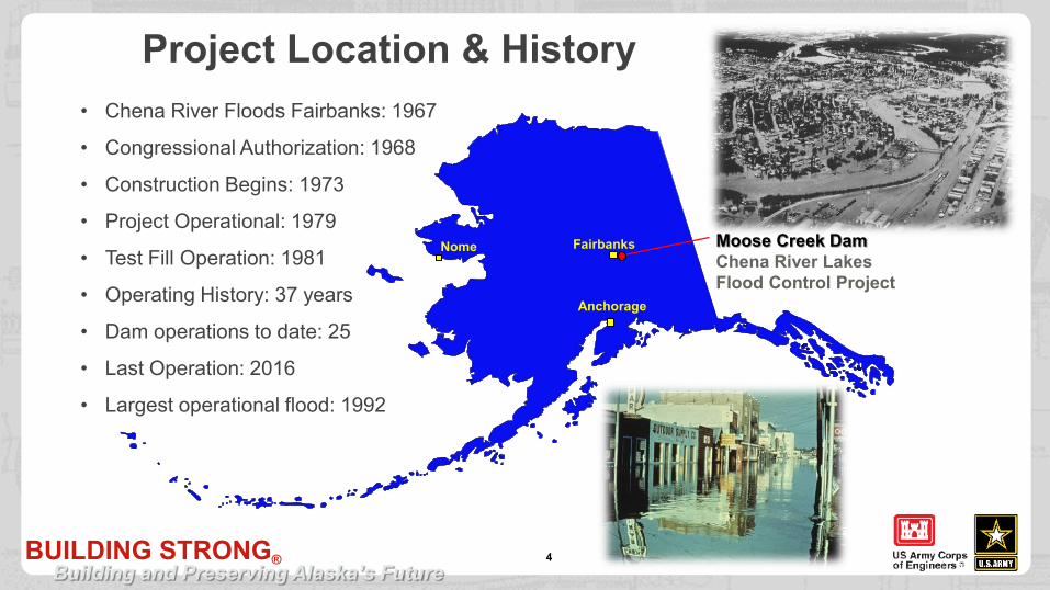
4
• Chena River Floods Fairbanks: 1967
• Congressional Authorization: 1968
• Construction Begins: 1973
• Project Operational: 1979
• Test Fill Operation: 1981
• Operating History: 37 years
• Dam operations to date: 25
• Last Operation: 2016
• Largest operational flood: 1992
Anchorage
FairbanksNome Moose Creek Dam Chena River Lakes Flood Control Project
Project Location & History

BUILDING STRONG®Building and Preserving Alaska’s Future
Floodway and Dam
5

BUILDING STRONG®Building and Preserving Alaska’s Future
6
• Over 165,000 visitors annually
• 16,000 acres of public land for dispersed low impact recreational activities and a variety of indigenous wildlife, migratory birds, and waterfowl
• ~25 special use/event permits issued annuallyincluding retriever dog trials, civil war reenactments, triathlons, cross country meets, trail riding, scouting events, and youth conservation camps.
• Almost annually the Project is proud to host a paralyzed veteran moose hunt for hunters selected from across the country.
• The Project partners with the Fairbanks North Star Borough, Alaska Department of Fish and Game, Bureau of Land Management/Alaska Fire Service, and the U.S Fish and Wildlife on a number of ongoing cooperative projects.
Recreational Uses/Benefits

BUILDING STRONG®Building and Preserving Alaska’s Future
PROJECT FEATURES
7

BUILDING STRONG®Building and Preserving Alaska’s Future
Chena RiverTanana RiverMCD
8
Geologic Overview
Foundation is gravelly sand/sandy gravel that likely exceeds 1000 ftthickness with a surficial blanket of silt
The transition from sand and gravel to silt includes layers of sand and silty sand, including fine sand with Cu<3.
The sand and gravel includes gap graded and open work gravel lenses.
Sloughs from meanders and braids, as well as permafrost, complicate the near surface geology.

BUILDING STRONG®Building and Preserving Alaska’s Future
Sand And Gravel• S&G is very heterogeneous across site
• The foundation materials are “sandy gravel to gravelly sand”
• About 1/4 of S&G samples are gap graded
• Open work gravel is present but rare
• Zones of erodible fine sand are present (Cu ≤ 7)
9
12-in3-in¾-in # 4#10 #40 #200 0.005 mm
0102030405060708090
100
0.0010.1101000
Per
cent
Fin
er b
y W
eight
Grain Size (mm)
12-in3-in¾-in # 4# 10 # 40 # 200 0.005 mm
0102030405060708090
100
0.0010.1101000Per
cent
Fin
er b
y W
eight
Grain Size (mm)
12-in3-in¾-in# 4# 10# 40# 200 0.005
mm
0102030405060708090
100
0.0010.1101000
Per
cent
Fin
er b
y W
eight
Grain Size (mm)
12-in3-in¾-in # 4#10 #40 #200 0.005 mm
0102030405060708090
100
0.0010.1101000
Per
cent
Fin
er b
y W
eight
Grain Size (mm)
Open Work Gravel Erodible Sand
Typical Insitu Soils
Gap Graded

BUILDING STRONG®Building and Preserving Alaska’s Future
• Permafrost is soil or bedrock that has been continuously frozen (0oC or less) for at least two years, with or without the presence of ice or water.
• An area of known discontinuous permafrost is present under the central portion of the dam.
• Permafrost excavation similar to rock excavation
10
Permafrost

BUILDING STRONG®Building and Preserving Alaska’s Future
11
Operational Schematic

BUILDING STRONG®Building and Preserving Alaska’s Future
Dam Features - General Layout
12
Weir
Sill
Floodway
Control Works
Low Point Drain
Relief Wells
Low Point Drain and South Seepage Collector
Channel
Embankment and Stability Berm

BUILDING STRONG®Building and Preserving Alaska’s Future
Relief Wells
13
• Six relief wells were installed during original construction
• Current count is 158 Relief Wells
• Relief Wells are a continuing O&M issue

BUILDING STRONG®Building and Preserving Alaska’s Future
EMBANKMENT DESIGN AND SEEPAGE CONTROL
14
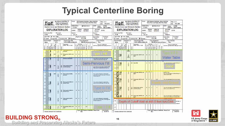
1. Moose Creek is a sand and gravel dam.2. A high-capacity seepage collection and
drainage channel system with a drainage ditch and lateral conduits to convey collected seepage through the stability berm.
3. A downstream stability berm to protect the embankment against heave.
4. A downstream toe drain, consisting of free-draining material.
5. Test relief wells, and greatly increasing the number of relief wells after 1981 test fill.
6. Extensive upstream impervious blanket (enlarged after the 1981 test fill).
Type I ≈ Type II
Type III ≈ Semi P. or
Type III ≈ Type I/II
BUILDING STRONG®Building and Preserving Alaska’s Future
Typical Centerline Boring
15

BUILDING STRONG®Building and Preserving Alaska’s Future
DAM SAFETY CONCERNS
16

BUILDING STRONG®Building and Preserving Alaska’s Future
Reaches
17
Project Office
Rea
ch
4 Rea
ch
5

BUILDING STRONG®Building and Preserving Alaska’s Future
Dam Safety Issues: Actionable Potential Failure Modes Backward Erosion and Piping with Vertical Exit (BEPv) Backward Erosion and Piping with Horizontal Exit (BEPh) Contact Erosion
18
Fine Sandy/Silty Sand
Open Work Gravel
Contact Erosion
Contributing Factors Flaw is a continuous fine sand layer
Roof is a continuous silt layer
Unfiltered exit is a pre-existing defect or is created during
the flood event by blowout of the downstream silt blanket
Average horizontal gradients are sufficient to initiate BEP
No upstream flow limiter exists
Backward Erosion and Piping with Vertical or Horizontal Exit

BUILDING STRONG®Building and Preserving Alaska’s Future
2014 – 2016 Floods - Sand Boils
19
Majority of boils found from Station 285+00 to 294+00 (Reach 4) and Station 306+75 to 307+75 (Reach 5) Boil classification Silt Cone Size Range (Feet) Typical Throat Size (Inches)
Small/Pin 0.0 to 0.5 0.25 to 1.0
Medium 0.5 to 2.0 1.0 to 2.0
Large 2.0 to 4.0 1.0 to 9.0
Extra Large 4.0 to 10.0 or larger 4.0 to 12.0
Height of boils ranged from an inch to one foot and typically equalized with tail water level.
to

BUILDING STRONG®Building and Preserving Alaska’s Future
PLAN FORMULATION PROCESS
20

BUILDING STRONG®Building and Preserving Alaska’s Future
21
Initi
al A
rray
Appl
y To
R
each
es
Fina
l Arr
ay
Screening Screening Screening Screening
Form
ulat
e M
easu
res
47 Measures
5 Reaches
9 Reaches
7 Alternatives24 Measures
36 Alternatives
0 F Plans
8 F Plans
• Found a critical flaw in assumptions made to create a single stage filter material that would work with materials ranging from silt to openwork gravels.
Alternatives
Alt 6 Trench
Alt 15 Upstream Geomembrane
Alt 18 Berm Extension with Decommissioned Relief Wells
Alt 21 Trench, Berm and Decommissioned Relief Wells
Alt 27 Trench, Berm, Decommissioned Relief Wells, and Geomembrane
Alt 36 Berm, Decommissioned Relief Wells, Geomembrane
F Plans
F0 Berm & Trench in Reach 4
F1 Berm and Trench in Reaches 4-6
F2 Berm and Trench in Reaches 4-6, Trench in Reaches 8 & 9
F3 Berm and Trench in Reaches 4-6, Trench in Reaches 2, 3, 8, and 9
F4 Berm and Trench in Reaches 4, 5, 6, 8, & 9, Trench in Reaches 2 & 3
F5 Berm and Trench in Reaches 2, 3, 4, 5, 6, 8, & 9
F6 Trench in Reaches 3, 4, 5, 6, 8, & 9
F7 Trench in Reaches 4, 5, 6, 8, & 9
Plan Formulation Strategy – Phase I
BUILDING STRONG®Building and Preserving Alaska’s Future
22
TSP
Initi
al A
rray
Appl
y To
R
each
es
Fina
l Arr
ay
Screening Screening Screening Screening
Form
ulat
e M
easu
res
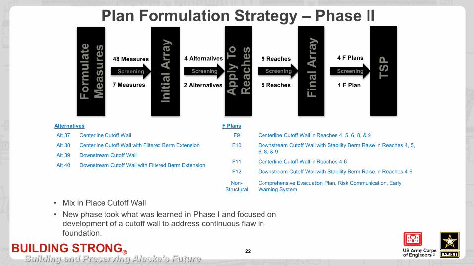
7 Measures
48 Measures
2 Alternatives
4 Alternatives
1 F Plan
4 F Plans
5 Reaches
9 Reaches
• Mix in Place Cutoff Wall• New phase took what was learned in Phase I and focused on
development of a cutoff wall to address continuous flaw in foundation.
Alternatives
Alt 37 Centerline Cutoff Wall
Alt 38 Centerline Cutoff Wall with Filtered Berm Extension
Alt 39 Downstream Cutoff Wall
Alt 40 Downstream Cutoff Wall with Filtered Berm Extension
F Plans
F9 Centerline Cutoff Wall in Reaches 4, 5, 6, 8, & 9
F10 Downstream Cutoff Wall with Stability Berm Raise in Reaches 4, 5, 6, 8, & 9
F11 Centerline Cutoff Wall in Reaches 4-6
F12 Downstream Cutoff Wall with Stability Berm Raise in Reaches 4-6
Non-Structural
Comprehensive Evacuation Plan, Risk Communication, Early Warning System
Plan Formulation Strategy – Phase II

BUILDING STRONG®Building and Preserving Alaska’s Future
TENTATIVELY SELECTED PLAN
23

BUILDING STRONG®Building and Preserving Alaska’s Future
Tentatively Selected Plan
Plan F9:► Centerline Cutoff Wall: Reaches 4, 5, 6, 8, 9► Addresses Flaw (biggest risk driver). The
Cutoff Wall will interrupt and discontinue the flaw.
► Minimal environmental impacts.► Less uncertainty with untested embankment
performance.► Meets Planning Objectives (TRG) with High
Level of certainty.► Reduces risk around 1 order of magnitude
below Tolerable Risk Guidelines.
24
BUILDING STRONG®Building and Preserving Alaska’s Future
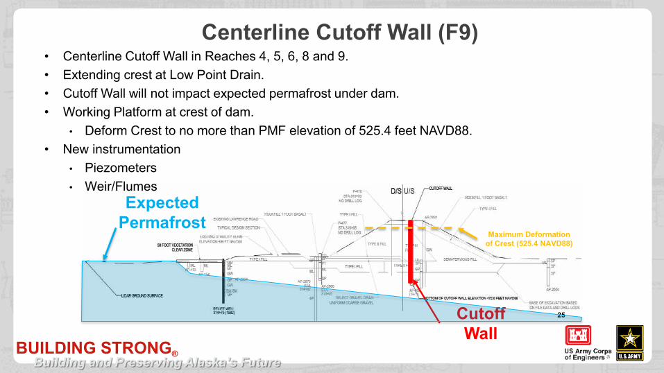
Centerline Cutoff Wall (F9)
25Cutoff Wall
• Centerline Cutoff Wall in Reaches 4, 5, 6, 8 and 9.• Extending crest at Low Point Drain.• Cutoff Wall will not impact expected permafrost under dam.• Working Platform at crest of dam.
• Deform Crest to no more than PMF elevation of 525.4 feet NAVD88.• New instrumentation
• Piezometers• Weir/Flumes
ExpectedPermafrost
Maximum Deformation of Crest (525.4 NAVD88)

BUILDING STRONG®Building and Preserving Alaska’s Future
Centerline Cutoff Wall – Plan View & Typical Section
26

BUILDING STRONG®Building and Preserving Alaska’s Future
Control Structure and Low Point Drain – Tie-ins
27
• Cutoff wall will require tie-in with Control Structure located within Reach 7 and Low Point Drain in Reach 5• Sheet Pile• CSM Wall
23 feet
60 feet

BUILDING STRONG®Building and Preserving Alaska’s Future
Geophysical Investigation Ground Penetrating Radar (GPR) Capacitively Coupled Resistivity (CCR) Electrical Resistivity Tomography (ERT) 3 Longitudinal Lines
• Upstream Dam Toe• Centerline • Downstream Stability Berm Toe
• 9 Transects
28
9 Transects of Dam250+00 (Reach 3-4) 399+00 (Old Chena River Slough)
290+00 (Boils/Permafrost) 411+50 (Old Chena River Slough)
320+00 (Reach 4-5) 440+00 (Reach 8-9)
338+00 (3-4 feet of silty fine sand) 480+00 (Near North Abutment)
380+00 (Reach 5-6)

BUILDING STRONG®Building and Preserving Alaska’s Future
Geophysical Results
29File Name

BUILDING STRONG®Building and Preserving Alaska’s Future
Geophysical Results
30
GPR
ERTCCR

BUILDING STRONG®Building and Preserving Alaska’s Future
Geotechnical InvestigationProposed Number and Depths of Soil Borings
Boring Location Depth (ft) Number of Borings Total Depth (ft)
Centerline Dam 90 24 2,160
Centerline Dam 50 1 50
Centerline Dam 130 1 130
Centerline Dam 100 1 100
Upstream Dam 60 2 120
Downstream Dam 130 14 1,820
Downstream Dam 60 8 480
Total: 51 4,860 feet
Additional Borings
Downstream Dam 130 2 260
New Total: 72 5120 feet
Sonic Drilling • Savannah District sonic rig with Alaska District
Engineers.• Ground truth for geophysics.• Obtain material for mix design. • Installation of 3 piezometers.• Look for aquitard around 90-110 feet below ground
surface.• Test borings are on ~1200 foot intervals. Subject to be
adjusted based on findings of geophysical investigation.
Drilling Methods• Sonic drilling with minimal water through embankment
and foundation.• Continuous sampling to depth of interest.
31

BUILDING STRONG®Building and Preserving Alaska’s Future
UNIQUE SITEAND CLIMATE CONDITIONS
32
BUILDING STRONG®Building and Preserving Alaska’s Future
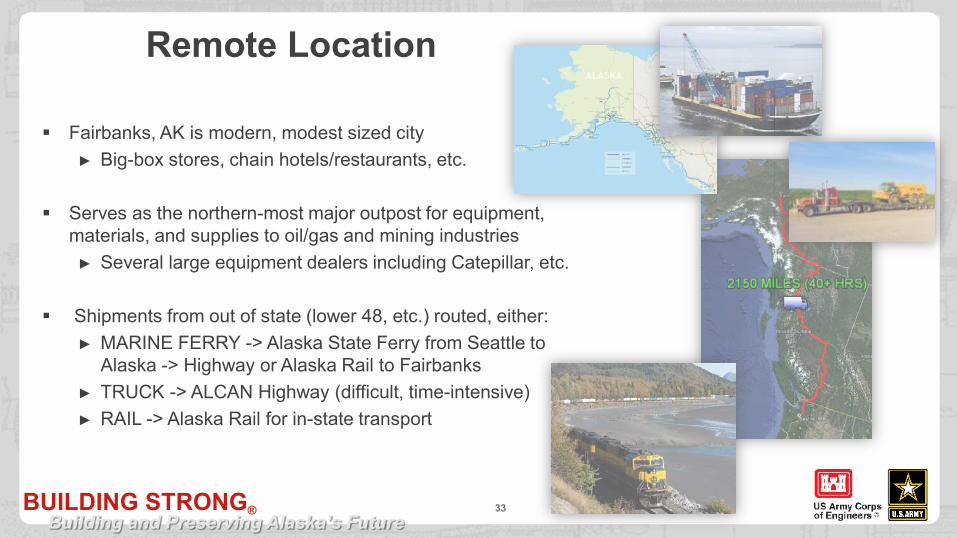
Remote Location
33
Fairbanks, AK is modern, modest sized city► Big-box stores, chain hotels/restaurants, etc.
Serves as the northern-most major outpost for equipment, materials, and supplies to oil/gas and mining industries
► Several large equipment dealers including Catepillar, etc.
Shipments from out of state (lower 48, etc.) routed, either:► MARINE FERRY -> Alaska State Ferry from Seattle to
Alaska -> Highway or Alaska Rail to Fairbanks► TRUCK -> ALCAN Highway (difficult, time-intensive)► RAIL -> Alaska Rail for in-state transport

BUILDING STRONG®Building and Preserving Alaska’s Future
Limited Commercial Aggregate Sources Generally, transportation of aggregate materials throughout the state is costly and
seasonally restricted Most large projects are sourced from on-site borrow pits Even commercially available aggregates are generally quarried locally, and produced to
order
34

BUILDING STRONG®Building and Preserving Alaska’s Future
Varied Duration of Daylight Hours
35
Source: https://www.timeanddate.com/sun/usa/fairbanks

BUILDING STRONG®Building and Preserving Alaska’s Future
Varied Duration of Daylight Hours
36
Source: https://www.timeanddate.com/sun/usa/fairbanks

BUILDING STRONG®Building and Preserving Alaska’s Future
Extreme Low Temperatures & Annual Range H/L
37
Source: http://www.intellicast.com
Freeze/Snow/
short days
Freeze/Snow/
short days
DOT Hwy Load
Restrictions

BUILDING STRONG®Building and Preserving Alaska’s Future
Heave/Frost Jacking
38
• Relief wells/other feature extending through the frost zone experience significant loading due seasonal frost heave/jacking

BUILDING STRONG®Building and Preserving Alaska’s Future
CSM BARRIER WALLCONSTRUCTION METHODS
39

BUILDING STRONG®Building and Preserving Alaska’s Future
Barrier Wall Technologies Slurry Trench
► Clamshell
► Continuous Chain Trenching
► Hydraulic Excavator
► Jet-Grouting
Cutter Soil Mixing
► Continuous Chain Trenching
► Hydromill
► Secant Pile
► Multiple auger
Many more…
40

BUILDING STRONG®Building and Preserving Alaska’s Future
Embankment Design And Seepage Control
41
1. Moose Creek is a sand and gravel dam.
2. A high-capacity seepage collection and drainage channel system with a drainage ditch and lateral conduits to convey collected seepage through the stability berm.
3. A downstream stability berm to protect the embankment against heave.
4. A downstream toe drain, consisting of free-draining material.
5. Test relief wells, and greatly increasing the number of relief wells after 1981 test fill.
6. Extensive upstream impervious blanket (enlarged after the 1981 test fill).
Type I ≈ Type IIType III ≈ Semi P.
orType III ≈ Type I/II

BUILDING STRONG®Building and Preserving Alaska’s Future
Moose Creek - Barrier Wall Technologies Slurry Trench
► Clamshell
► Continuous Chain Trenching
► Hydraulic Excavator
► Jet-Grouting
Cutter Soil Mixing
► Continuous Chain Trenching
► Hydromill
► Secant Pile
► Multiple auger
Many more…
42

BUILDING STRONG®Building and Preserving Alaska’s Future
Design & Budgeting Considerations Several state-of-the-art technologies exist for CSM wall
construction► Most are proprietary, custom-built machines unique to
specific construction firms► Some technologies are more competitive than others
depending on the wall design and site arrangement. Equipment access & hauling materials often drive production
► Work platform (25’-50’ wide) required to accommodate construction traffic around CSM machines
► Size/arrangement of work platform varies by specific technology employed
► Accommodations for work platform can be significant $• Degrade dam crest• Rock fill• Paved work surfaces
Therefore, it is difficult to budget to specific technology AND foster competitive bid market
44
Herbert Hover Dike - Florida

BUILDING STRONG®Building and Preserving Alaska’s Future
Far North/Remote Location Considerations
45
Availability of machines within industry to mobilize Mobilization related costs for specialty equipment Winterization/standby related costs for specialty equipment Availability within local/regional labor market Availability of local/regional construction equipment
► Haul trucks & teamsters Seasonal on-highway load restrictions Commercial availability of large quantities of anything… especially
aggregates

BUILDING STRONG®Building and Preserving Alaska’s Future
Cold Weather Considerations for CSM
46
Typical civil/earthwork construction season is 7 of 12 months, due to cold temps, snow, and reduced daylight, and DOT highway load restrictions
CSM work in far north has been successfully demonstrated by industry, including work through winter months.
Freezing weather reduces production, machines do better in 24/7 operation
Maintenance of haul routes

BUILDING STRONG®Building and Preserving Alaska’s Future
47
For More… USACE Alaska District – Moose Creek Project Website
http://www.poa.usace.army.mil/Locations/Chena-River-Lakes-Flood-Control-
Project/
Chena Google Virtual Project Tourhttps://www.youtube.com/watch?v=IUwReK5FEfE
USACE “AlaskaCorps” YouTube® Channelhttps://www.youtube.com/user/AlaskaCorps

BUILDING STRONG®Building and Preserving Alaska’s Future
48
Questions, Comment, or Discussion?
Chena River Lakes Flood Control Project/Moose Creek Dam, North Pole, Alaska - USACE
Design, Cost, And Constructability Considerations For CSM Barrier Walls In The Far North