Embed Size (px)
Citation preview
a SpringerOpen Journal
Dumond and Baddour SpringerPlus 2013, 2:558http://www.springerplus.com/content/2/1/558
RESEARCH Open Access
Can a brace be used to control the frequencies ofa plate?Patrick Dumond* and Natalie Baddour
Abstract
Although many improvements in the manufacturing of guitars have been made recently, one aspect that has oftenbeen overlooked is that of the acoustical consistency of the final manufactured product. The aim of this paper is tocreate a better understanding of the effect of a brace on the frequencies of vibration of the brace-soundboard system.This paper seeks to shed light on why a luthier ‘tunes’ braces when a guitar soundboard is hand-manufactured. Asimple analytical model of a rectangular brace and soundboard is derived from first principles using Kirchhoff platetheory in order to develop insight into the effect of the soundboard’s stiffness and brace thickness on the frequenciesof the combined system. Natural frequencies and modeshapes of the combined system are calculated via the assumedshape method. Results show that by adjusting the thickness of the brace in order to compensate for the stiffness ofthe plate, one of the natural frequencies of the combined system can be adjusted to meet a desired value. However,simultaneously adjusting several natural frequencies cannot be done with a rectangular brace. Therefore modificationsto the shape of the brace are explored.
Keywords: Frequency matching; Assumed shape method; Brace-plate system; Musical instrument; Plate vibration;Orthotropic material; Tuning; Design-for-frequency; Spectrum control
IntroductionThe scientific study of guitars and other stringed musical in-struments has been around for over a half century and manyimprovements to their production manufacturing have alsobeen made (Richardson 1990; Chaigne 1999; French 2008a).In spite of this, manufactured instruments often do notsound as good as instruments built by hand by experiencedluthiers. With precision tooling, production manufacturedinstruments can be built to strict dimensional tolerancesand yet, acoustical consistency of the final product is stillnot ensured –meaning that two instruments emerging fromthe same production line will be dimensionally identical butacoustically different (French 2008b). There are two princi-pal reasons for the lack of acoustical consistency. The firstis that wood is a natural material, with natural variationsso that soundboards that are dimensionally identical maybe acoustically quite different. The other reason is that thetuning process used by the experienced luthiers to hand-build and tune instruments is based on years of experienceand tradition but scientifically is not well understood. This
* Correspondence: [email protected] of Mechanical Engineering, University of Ottawa, 161 LouisPasteur, CBY A205, K1N 6N5 Ottawa, Canada
© 2013 Dumond and Baddour; licensee SpringCommons Attribution License (http://creativecoreproduction in any medium, provided the orig
tuning process is what luthiers use to make up for the nat-ural variation in the acoustical properties of wood and sincethis tuning process is not well understood analytically, it isimpossible to replicate autonomously. The goal of thispaper is thus to develop a better analytical understanding ofthe tuning process of a guitar soundboard during its manu-facture. The ultimate end goal is that this understandingcan eventually be used to develop an automated tuningprocess to be used during guitar manufacture.While all parts of a guitar contribute to the overall sound,
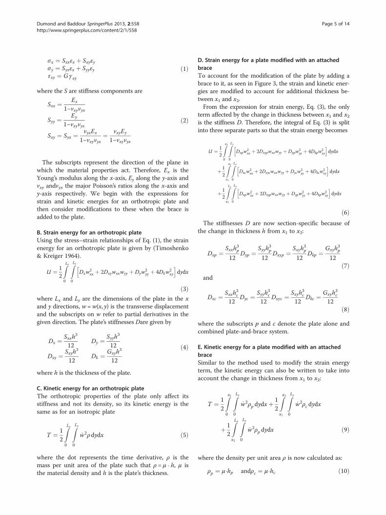
there is general agreement that it is the soundboard, alsoknown as the top plate, of the guitar that is most acoustic-ally active and for which the highest inconsistency exists(Siminoff 2002a). The design of the soundboard serves twopurposes, one structural and one musical. The first purposeis to structurally resist the immense tension of the stringsand the second purpose is to produce the sound associatedwith the guitar. In order for the soundboard to be flexibleenough to vibrate at the desired frequencies, it is quite thin.This makes the soundboard structurally unsuitable to resistthe immense string tension. In order to compensate for this,braces are added to the underside of the soundboard as seenin Figure 1. While their function is primarily structural, they
er. This is an open access article distributed under the terms of the Creativemmons.org/licenses/by/2.0), which permits unrestricted use, distribution, andinal work is properly cited.

Soundboard
Braces
Figure 1 Underside of a braced guitar soundboard.
Dumond and Baddour SpringerPlus 2013, 2:558 Page 2 of 14http://www.springerplus.com/content/2/1/558
can also be used to adjust the frequencies of thesoundboard-brace system. Soundboard frequency adjust-ments are known as tuning and this can be effectively doneby varying the number and position of braces, as well as bychanging their dimensions. For luthiers trying to follow atraditional bracing pattern, adjustment of the dimensions ofthese braces is generally the preferred method by which aguitar soundboard is tuned (Siminoff 2002b).The method most widely used by luthiers for optimising
the brace and soundboard combination is known as tap tun-ing. Tap tuning involves listening to the change in frequencycaused by the removal of brace material. The material is re-moved from the brace by hand and the tap-tuning processis an iterative process which involves tapping, listening andremoving of brace material. By removing material fromthe brace, its stiffness is reduced as well as its mass;however the removal of wood has a larger impact onstiffness than on mass so the natural frequencies are re-duced (Elejabarrieta et al. 2000). Since there is commonconsensus that the lower modes of vibration are of greaterimportance, generally only the lower natural frequenciesare observed (Richardson 1990; Hutchins & Voskuil 1993;Natelson & Cumpiano 1994). This optimisation processoften leads to what is known as scalloped braces, as shown
Figure 2 Shape of a scalloped brace.
in Figure 2. Much debate still exists as to the acoustic ben-efits of scalloped braces and the whole tuning process isstill not well understood (Siminoff 2002b).On the other hand, for production-manufactured instru-
ments, current practice in the industry is to test the acous-tic quality of a soundboard by measuring its stiffnessacross the grain during the manufacturing process (French2008a). The deflection across the grain of the soundboardwithout braces is measured under a known load. Based ona certain set of deflection ranges, the soundboards arejudged to be of higher or lower acoustical quality and aretherefore used in different product lines. This test gives anidea as to the soundboard’s stiffness and thus the resultingfrequency range of the final product. Based on the sound-board’s stiffness test, a brace from a collection of pre-dimensioned braces is chosen for that soundboard. A cer-tain quality control is obtained since the manufacturer isaware of the range of soundboard stiffness for which theirdimensioned braces produce decent instruments.The fact that dimensional changes to the braces have a
substantial impact on the frequency spectrum of the gui-tar is known but the extent of this effect is still unknown.However, research into the acoustics of musical instru-ments has begun to explain the fundamental interaction

Dumond and Baddour SpringerPlus 2013, 2:558 Page 3 of 14http://www.springerplus.com/content/2/1/558
between various components of an instrument (Caldersmith1995) and also the effect on the resulting sound field.Loosely generalized, research into guitars and other instru-ments has focused on their radiated sound fields or on theirmodal properties. Over the years, several experimental andcomputational techniques have been applied to the study ofguitars, and in particular soundboards. One area of investi-gation has been the visualization of guitar box and sound-board resonances via holography and laser interferometry(Jansson 1971; Stetson 1981; Firth 1977; Richardson 2010;Jovicic 1977).The radiation fields of the guitar have also been studied
numerically and experimentally (Brooke & Richardson1993a; Brooke & Richardson 1991b; Lai & Burgess 1990;Hill et al. 2004). Recent work has demonstrated that a rela-tively small number of measured parameters are requiredto predict the sounds radiated by a guitar (Richardson2010; Hill et al. 2004; Richardson 2005). Interestingly,Brooke and Richardson conclude that there are no simplerelationships between the modal properties of instrumentsand their estimated “quality” (Brooke & Richardson 1993a).At first glance this is surprising, although this is likely thescientific equivalent to the musical statement that just be-cause an instrument is in tune does not ensure it is a“quality” instrument. On the other hand, most musicianswill reject out of tune instruments as unplayable thereforeone might infer that “good” modal properties are neces-sary but not sufficient to ensure a decent instrument.However, there does not seem to be a consensus on whatconstitutes “good” modal properties.Elejabarrieta, Ezcurra, and Santamarı́a performed an ex-
tensive set of experimental and numerical studies on a gui-tar through its entire construction process by a masterluthier. They experimentally tested the soundboard at eachconstruction step as modifications were made by the lu-thier, in order to understand the effect of his modificationson the vibration properties of the soundboard (Elejabarrietaet al. 2000). This was followed by a finite element analysisof the same data (Elejabarrieta et al. 2001). As the guitarcontinued to be built by the same luthier, they continuedwith their work by analyzing the resonance box and itsmodes of vibrations, along with the effect of the sound-holeon the acoustic modes of the box (Elejabarrieta et al.2002a). Their next step was an experimental and finiteelement analysis of the coupling of the vibration modes ofthe structural (soundboard and back-plate) and acoustic(the box as a Helmholtz resonator) modes once the box ofthe guitar had been assembled (Elejabarrieta et al. 2002b).Finally, they investigated the fluid-air interaction of the gui-tar box in which the interior gas was changed both experi-mentally and numerically (Ezcurra et al. 2005). This set ofwork contributed greatly to the understanding of how eachcomponent of the guitar contributes to the final frequenciesof vibration but did not offer any suggestions as to how an
instrument designer might modify a given component toachieve a specific acoustical objective. Boullosa experimen-tally measured the radiation efficiency and frequency con-tent of the vibrations of a classical guitar (Boullosa 2002;Boullosa et al. 1999) but offers little in the way of insight asto which components of the guitar or their modificationscontribute to either. Torres and Boullosa also studied theeffect of the bridge on the vibrations of the soundboardboth with finite elements and with laser vibrometry (Torres& Boullosa 2009). Chaigne and various collaborators fo-cused their research on the time-domain modelling of theguitar (Chaigne 1999; Bécache et al. 2005; Derveaux et al.2003) with the intent to better understand the vibroacousti-cal behavior via physical and numerical modeling. Their in-tent was for this to be used as a tool for the estimation ofquantities that are hard to measure experimentally as forexample the estimation of the relative structural losses andradiation losses in the sounds generated by the guitar.In other (non-musical) disciplines, stiffened plates have
been previously studied by various methods (Fox & Sigillito1980; Barrette et al. 2000; Peng et al. 2006; Hong et al.2006). However these studies have focused on the struc-tural properties of such systems rather than the acousticalproperties of the interaction between the beam and plateelements.Despite the work that has been done to understand the
mechanics of the instruments, little has been done to im-prove the acoustical consistency of manufactured guitarsin large part because the tuning process that is used forhand-built instruments is not well understood and thuscannot easily be replicated. The goal of this paper is tobegin to develop a better understanding of this tuningprocess via a simple analytical model to represent the vi-brations of an instrument soundboard and a supporting/tuning brace. A simple model is sufficient to answer thequestion at hand, therefore a simple model that can yieldthe most physical insight is chosen for the analysis. Thequestion is: can we change the dimensions of the brace tomake up for changes in stiffness of the soundboard so thatthe combined brace-soundboard system has desired fre-quencies of vibration? This is the essence of what luthiersdo when they hand-tune an instrument during its con-struction; they make small changes to the structural prop-erties in order to produce desired changes in acousticalproperties. An idea similar to this has been consideredanalytically for a xylophone (Orduna-Bustamante 1991),where the effect of an undercut on the bar on its tuningwas modelled and analyzed. However, to the best of theauthors’ knowledge, this type of analysis has not been con-sidered for a guitar.Current research shows that it is the first few modes of
the coupled system that are necessary in order to tune thesoundboard during manufacturing (Hutchins & Voskuil1993). In this work, the assumed shape method is used to

Dumond and Baddour SpringerPlus 2013, 2:558 Page 4 of 14http://www.springerplus.com/content/2/1/558
analyze the continuous system, with the modes of thesoundboard without the brace used as the solutionbuilding blocks. The assumed shape method is a globalelement method detailed in (Meirovitch 1996a). It hasbeen shown to be particularly usefully in the modal ana-lysis of stiffened and orthotropic plates (Xu et al. 2010;McIntyre & Woodhouse 1988). The assumed shapemethod has specifically been chosen as the analysis toolbecause it can solve the mass and stiffness matrices ana-lytically; thereby each matrix entry is a function of allphysical parameters. This helps give vibration insightabout the model’s natural frequencies and correspond-ing modes (Bisplinghoff et al. 1996).A brief outline of the paper is as follows. Section 2
presents the analytical model, specifically chosen basedon the pertinent background information provided inSection 1. Section 3 demonstrates the results of the re-search and Section 4 is a discussion of the results. Theeffects of scalloped braces are dealt with in Section 5.Finally, conclusions are given in Section 6.
Analytical model of the plate-brace systemA. Modeling assumptionsTo analytically investigate the brace/soundboard inter-action, we analyze the natural frequencies and mode-shapes of a rectangular plate model with an attachedcross-brace, as shown in Figure 3.The soundboard is modeled as a thin rectangular
Kirchhoff plate and the brace is modeled as a thickersection of the same plate. A simple rectangular geom-etry is assumed in order to enable the closed-form solu-tion of a simple plate (without the brace) to be used asthe trial functions for the assumed shape method. Fur-ther, since the solution of a rectangular plate is known
Figure 3 Orthotropic rectangular plate fitted with brace across its wid
in closed form, this will enable a direct comparison andenable the understanding of the effect of the brace onthe vibration properties of the plate.The Kirchhoff plate theory assumes small transverse
deflections and neglects transverse normal and shearstresses, as well as rotary inertia. Although this is an ac-curate assumption for the plate, due to the brace’sthickness-to-width aspect ratio, it may imply a certainerror in that region of the soundboard. Also, because ofthe method in which the brace thickness is added tothat of the plate in the kinetic and strain energy expres-sions, it was necessary to change the direction of thegrain of the plate, in this region only, to match that ofthe brace. This is reasonable since the plate is thin andthe properties of the brace dominate in this region. Theplate is also assumed to be simply supported all around,although in reality it is somewhere between simply sup-ported and clamped (Meirovitch 1996b). It has been as-sumed that the system is conservative in nature, whichallows damping to be neglected. Although there is acertain amount of damping found in wood, its effectson the lower natural frequencies is thought to be min-imal and has been neglected. This is justified becausethe tuning process (adding and adjusting the dimen-sions of the braces) has a greater effect on the lowerfrequencies than on the higher frequencies (Hutchins &Voskuil 1993).The orthotropic properties of wood are modeled, there-
fore its longitudinal and radial properties are of interest,labelled L and R respectively. The only material propertiesthat need to be considered independently in these direc-tions are Young’s modulus, E and Poisson’s ratio, ν. For anorthotropic plate the stress–strain relationships are givenby (Riley et al. 2006)
th.
Dumond and Baddour SpringerPlus 2013, 2:558 Page 5 of 14http://www.springerplus.com/content/2/1/558
σx ¼ Sxxεx þ Sxyεyσy ¼ Syxεx þ Syyεyτxy ¼ Gγxy
ð1Þ
where the S are stiffness components are
Sxx ¼ Ex
1−νxyνyx
Syy ¼ Ey
1−νxyνyx
Sxy ¼ Syx ¼ νyxEx
1−νxyνyx¼ νxyEy
1−νxyνyx
ð2Þ
The subscripts represent the direction of the plane inwhich the material properties act. Therefore, Ex is theYoung’s modulus along the x-axis, Ey along the y-axis andνxy andvyx the major Poisson’s ratios along the x-axis andy-axis respectively. We begin with the expressions forstrain and kinetic energies for an orthotropic plate andthen consider modifications to these when the brace isadded to the plate.
B. Strain energy for an orthotropic plateUsing the stress–strain relationships of Eq. (1), the strainenergy for an orthotropic plate is given by (Timoshenko& Kreiger 1964).
U ¼ 12
ZLx0
ZLy
0
Dxw2xx þ 2Dxywxxwyy þ Dyw
2yy þ 4Dkw
2xy
h idydx
ð3Þwhere Lx and Ly are the dimensions of the plate in the xand y directions, w =w(x, y) is the transverse displacementand the subscripts on w refer to partial derivatives in thegiven direction. The plate’s stiffnesses Dare given by
Dx ¼ Sxxh3
12Dy ¼ Syyh
3
12
Dxy ¼ Sxyh3
12Dk ¼ Gxyh
3
12
ð4Þ
where h is the thickness of the plate.
C. Kinetic energy for an orthotropic plateThe orthotropic properties of the plate only affect itsstiffness and not its density, so its kinetic energy is thesame as for an isotropic plate
T ¼ 12
ZLx0
ZLy
0
_w2ρdydx ð5Þ
where the dot represents the time derivative, ρ is themass per unit area of the plate such that ρ = μ ⋅ h, μ isthe material density and h is the plate’s thickness.
D. Strain energy for a plate modified with an attachedbraceTo account for the modification of the plate by adding abrace to it, as seen in Figure 3, the strain and kinetic ener-gies are modified to account for additional thickness be-tween x1 and x2.From the expression for strain energy, Eq. (3), the only
term affected by the change in thickness between x1 and x2is the stiffness D. Therefore, the integral of Eq. (3) is splitinto three separate parts so that the strain energy becomes
U ¼ 12
Zx10
ZLy
0
Dxpw2xx þ 2Dxypwxxwyy þ Dypw
2yy þ 4Dkpw
2xy
h idydx
þ 12
Zx2x1
ZLy
0
Dxcw2xx þ 2Dxycwxxwyy þ Dycw
2yy þ 4Dkcw
2xy
h idydx
þ 12
ZLxx2
ZLy
0
Dxpw2xx þ 2Dxypwxxwyy þ Dypw2
yy þ 4Dkpw2xy
h idydx
ð6ÞThe stiffnesses D are now section-specific because of
the change in thickness h from x1 to x2:
Dxp ¼Sxxh
3p
12Dyp ¼
Syyh3p
12Dxyp ¼
Sxyh3p
12Dkp ¼
Gxyh3p
12ð7Þ
and
Dxc ¼ Sxxh3c
12Dyc ¼ Syyh
3c
12Dxyc ¼ Sxyh
3c
12Dkc ¼ Gxyh
3c
12ð8Þ
where the subscripts p and c denote the plate alone andcombined plate-and-brace system.
E. Kinetic energy for a plate modified with an attachedbraceSimilar to the method used to modify the strain energyterm, the kinetic energy can also be written to take intoaccount the change in thickness from x1 to x2:
T ¼ 12
Zx10
ZLy
0
_w2ρp dydxþ12
Zx2x1
ZLy
0
_w2ρc dydx
þ 12
ZLxx2
ZLy
0
_w2ρp dydx ð9Þ
where the density per unit area ρ is now calculated as:
ρp ¼ μ⋅hp andρc ¼ μ⋅hc ð10Þ

Dumond and Baddour SpringerPlus 2013, 2:558 Page 6 of 14http://www.springerplus.com/content/2/1/558
F. The assumed shape methodThe assumed shape method is chosen because it allows usto use the flat-plate modeshapes as the fundamental build-ing blocks of the solution, thereby permitting observationof how the addition of the brace affects those fundamentalmodeshapes. This method also permits greater flexibility inanalyzing the effects of changes in brace dimensions sinceit enables the creation of an analytical solution from whichnumerical solutions can be quickly obtained for variousthicknesses of the brace. The equations of motion are de-rived using a computer algebra system (Maple). This yieldsmass and stiffness matrices where each matrix entry is afunction of all physical parameters (dimensions, density,stiffnesses, etc.). The effect of any parameter on the sys-tem’s eigenvalues can then easily be examined without hav-ing to re-establish the entire system model. Using theassumed shape method, it has also been found that onlytwo additional odd or even trial functions more than theone of interest are required for convergence (depending onwhether it is itself odd or even). The finite element methodwas also considered. While the FE method offers signifi-cant advantages over the other approximate methods,namely its ability to model complex systems and boundar-ies and a high numerical accuracy, its disadvantage for thepurpose of this work is its inability to make use of theknown mode shapes of the system without the brace. Fur-thermore, the FE method also requires a large number ofdegrees of freedom in order for the solution to converge toaccurate results. Contrary to the nature of the global func-tions approach, the finite element method uses local func-tions which extend over small subdomains of the system(Meirovitch 1996b), thus comparison of the global behav-iour to the exact solution of a simple plate problem cannotbe directly incorporated into this solution approach.The first step of the assumed shape method is to
approximate the transverse displacement w(x, y, t) as(Meirovitch 2001)
w x; y; tð Þ ¼Xmx
nx¼1
Xmy
ny¼2
ϕnxny x; yð Þ⋅qnxny tð Þ ð11Þ
The ϕnxny are the chosen discrete spatial trial functions
and qnxny tð Þ are the generalized (time-dependent) coordi-
nates. Also, mx and nx represent the mode number and trialfunction number in the x direction respectively and my andnyrepresent the same in the y direction. Next, the trial func-tions are chosen so as to satisfy the geometric boundaryconditions and be complete in order to ensure convergenceof the solution (Meirovitch 2001). No other considerationsof the boundary conditions need to be taken into account.A simply supported plate implies boundary conditions suchthat the transverse displacement w of the perimeter of theplate is zero (Meirovitch 1996b).
Here, the modeshapes of the simply supported rect-angular plate (without the brace) are known and thesewill be used as the trial functions in Eq. (11), so that
ϕnxny ¼ sin nx⋅π⋅xLx
� �⋅ sin ny⋅π⋅
yLy
� �ð12Þ
Applying the trial functions of Eq. (12) to Eq. (11),gives a discrete series
w x; y; tð Þ ¼Xmx
nx¼1
Xmy
ny¼2
sin nx⋅π⋅xLx
� �⋅ sin ny⋅π⋅
yLy
� �⋅qnxny tð Þ
ð13Þwhich is then used in the strain and kinetic energy equa-tions of the modified plate.Once the strain and kinetic energies have been assem-
bled, Lagrange’s equations are used to find the equationsof motion which can then be written in matrix form as
M €q→ þK q→ ¼ 0
→ ð14Þwhere M is the mass matrix and K is the stiffness matrix
given. Additionally, q→ is the generalized coordinate vector
q→¼ q11 q12 q21 q22 …½ �T ð15ÞLetting the generalized coordinate system have a har-
monic solution as in (Meirovitch 1996b), then
q→ ¼ A→
cos ωt þ ϕð Þ ð16ÞHere, ω is the system’s natural frequency, ϕ the phase
shift and A→
is a magnitude vector of dimension(mx ⋅my) × 1.Then replacing the assumed harmonic solution into theequation of motion, Eq. (14) an eigenvalue problem is ob-tained, from which the natural frequencies and modeshapesare found.
ResultsThe purpose of this analysis is to verify if it is possible toalter the dimensions of the brace so as to obtain a desiredset of natural frequencies from the coupled system, know-ing their respective properties before assembly. Both sym-bolic and numerical computational tools are used.
A. Material propertiesThe material used throughout the analysis is that of Sitkaspruce, the most commonly used wood for stringed musicalinstrument soundboards. Material properties for Sitka spruceare obtained from the U.S. Department of Agriculture,(Forest Products Laboratory (US) 1999). Since propertiesbetween specimens of wood have a high degree of vari-ability, the properties obtained from the Forest ProductsLaboratory are an average of specimen samplings. The

Dumond and Baddour SpringerPlus 2013, 2:558 Page 7 of 14http://www.springerplus.com/content/2/1/558
naturally occurring properties of wood act as an orthotropicmaterial. Material properties of Sitka spruce are seen inTable 1. The subscripts ‘R’ and ‘L’ refer to the radial andlongitudinal property directions of wood respectively.
B. Plate and brace dimensionsA control test specimen, having the same dimensions forevery analysis, is used. The dimensions of the plate andbrace are based on typical dimensions of a section of in-strument soundboard for which a single brace is usedfor structural reinforcement. This turns out to be abouta quarter of a typical guitar soundboard. The brace di-mensions are defined as in Figure 4.The plate dimensions are defined as in Figure 3. Other
important reference points are also indicated. All the di-mensions used in this study for the brace and the plateas well as other pertinent reference points are listed inTable 2. To avoid confusion, subscript ‘p’ stands forplate, ‘b’ for brace and ‘c’ for combined plate and brace.
C. Frequencies and modeshapesThe assumed shape method used 10 × 10 trial functions.Table 3 gives these results of this modelling approach.Additionally, results of the natural frequencies obtainedvia the assumed shape method for the first ten modeswere compared to those obtained using the finite elem-ent method with over 21000 nodes. This served to verifyand validate the results presented here.The dip in the center of the x-axis for the assumed
shape method modeshapes is the location of the brace,which is visible on the modeshapes. The brace stiffensthis area and limits the amount of displacement that canoccur. Since the Kirchhoff model is used, shear and ro-tary inertia are neglected, which may induce some inac-curacies near the brace as the aspect ratio is larger there.
D. Effect of the brace on the natural frequencies of thecombined systemSystems having components combined using a rigid linkhave the sum of the stiffness and of the mass componentsof each subsystem, leading to natural frequencies whichgenerally fall somewhere between the two separate systems’
Table 1 Material properties for Sitka spruce as anorthotropic material (Forest Products Laboratory (US) 1999)
Material Properties Values
Density – μ (kg/m3) 403.2
Young’s modulus – ER (MPa) 850
Young’s modulus – EL (MPa) ER/0.078
Shear modulus – GLR (MPa) EL × 0.064
Poisson’s ratio – νLR 0.372
Poisson’s ratio – νRL νLR × ER/EL
original natural frequencies. To verify this claim on thecontinuous system, the original orthotropic system’s nat-ural frequencies are compared to those of the combinedorthotropic system in Table 4. The exact values for thenatural frequencies of the brace seen in Figure 4 usingclassical beam theory are given in (Hartog 2008). Theexact values for the natural frequencies of the simply sup-ported orthotropic plate of Figure 3 are calculated via theassumed shape method using the exact modeshapes ob-tained from (Meirovitch 1996b).These results show intuitive trends which help verify the
model and help in the understanding of the effect thatadding a brace has on the coupled system. A detailed dis-cussion about the relationship between these results isgiven in Section 4.
E. TuningIn order to verify the feasibility of tuning braces to aplate having a predetermined cross-grain stiffness, it isnecessary to look at effects of a change in both theYoung’s modulus in the radial direction ER and of thebrace thickness hb, on the modified orthotropic plate ofFigure 3. Although the lowest five natural frequenciescarry importance, only two will be observed during thevariation in structural properties. This is because fre-quencies that have a mode of vibration which contains anode at the location of the brace are not as affected bythe brace as those which have a mode which passesthrough it. Therefore the two frequencies observed dur-ing this analysis are the first and fourth natural frequen-cies of the orthotropic plate-brace system. The secondand third modeshapes have a node at the location of thebrace and are not as affected by the brace, contrary tothe first and fourth modeshapes which don’t. This canbe observed in Table 4, where the first and fourthmodes use only one trial function along the x-axis suchthat ω1:mx = 1,my = 1 and ω4:mx = 1,my = 2.Since it seems that the cross-grain stiffness of a sound-
board has a large impact on its acoustical properties andsince this stiffness is related to the soundboard’s radialYoung’s modulus, the radial Young’s modulus or ER is var-ied to see its effect on the systems natural frequencies.The brace is kept to a constant thickness of hb =0.012m.The results of this are shown in Figure 5.It is clear from Figure 5 that as ER increases, so do the
1st and 4th natural frequencies. A similar analysis isagain performed, but this time ER is held constant at850MPa and the thickness of the brace or hb is varied.These results are shown in Figure 6.In the same way as the previous case, it can be seen
from Figure 6 that when hb increases so do the 1st and4th natural frequencies of the combined system.Based on these results and in order to verify if it is pos-
sible to get consistency out of the natural frequencies, an

Figure 4 Brace showing pertinent dimensions.
Dumond and Baddour SpringerPlus 2013, 2:558 Page 8 of 14http://www.springerplus.com/content/2/1/558
analysis was performed in which an increase in the plate’sradial stiffness was compensated by reducing the thicknessof the brace, shown in Table 5. The plate’s radial stiffnessand the thickness of the brace were varied so as to keepthe 1st natural frequency relatively constant while examin-ing the effect this would have on the 4th natural frequency.It is apparent from Table 5 that although the first nat-
ural frequency has been held more or less constant, thisalso resulted in significant variation in the fourth naturalfrequency. This led to a further analysis in which the ra-dial stiffness and brace thickness were varied so that thefourth natural frequency was held constant, as shown inTable 6.Once again, forcing the fourth natural frequency to be
more or less constant causes the first natural frequency tovary considerably from its value at Er = 850 MPa. These re-sults are further discussed in the next section.
DiscussionBased on the results presented in Section 3, the analysis hasdemonstrated clear trends in the behaviour of a sound-board having a brace across its width. Specific points arediscussed herein.
A. Material propertiesThe first thing to note during this analysis is the use of thestatistical average values of spruce’s material properties. It isobvious that these material properties vary on a specimenby specimen basis. However the assumption was made that
Table 2 Test specimen dimensions
Dimensions Values
Length – Lx (m) 0.24
Length – Ly (m) 0.18
Length – Lb (m) 0.012
Reference – x1 (m) Lx/2 – Lb/2
Reference – x2 (m) x1 + Lb
Thickness – hp (m) 0.003
Thickness – hb (m) 0.012
Thickness – hc (m) hp + hb
there is a relationship between the radial stiffness ER and theother properties. While this is definitely alluded to by the(Forest Products Laboratory (US) 1999), it is unclear howmuch variation is actually present in these relationships.Based on years of luthier experience in using the cross-grainstiffness as a measure of soundboard quality, it would appearthat the relationship between this stiffness and other proper-ties is more consistent than the properties themselves. Itwould, however, be quite interesting to further investigatethis phenomenon, as this is has been found to be a greatway of modeling the material properties of wood.Clear, quartersawn, musical instrument spruce has been
shown to have remarkably consistent microscopic propertiesin spring and summer growth. Furthermore, spruce displaysan abrupt transition period which means that micro-scaleproperties are generally in line with macro-scale mechanicalproperties (Kahle & Woodhouse 1994). Therefore, by avoid-ing visual imperfections as is currently being done in indus-try, it is reasonable to assume that bulk material propertiestaken on a specimen-by-specimen basis is an adequatemeasure of overall system performance. However, it wouldbe interesting to investigate how localized changes in mater-ial properties would affect system performance, especially atthe location of the brace. Modifications to the method, byincreasing the number of zones of interest in the kinetic andstrain energy equations for example, could take into ac-count micro-scale variations in the material specimen. Onthe other hand, more rigorous testing of material proper-ties would be necessary to populate the input informationrequired for the analysis. On the macro-scale, CNC ma-chinery could be reprogrammed to shape braces as re-quired by the material property measurements of the plate.To increase the accuracy of the model by including
frequency-dependent damping properties, an analyticalapproach such as that described in (McIntyre & Wood-house 1988) could be used to modify the mathematicalmodel in order to take damping into account.
B. DimensionsThe dimensions used on the test specimen consisting ofthe simply supported rectangular plate and brace acrossthe width, are based on typical dimensions of those used

Table 3 Results for the assumed shape with 10x10 trialfunctions (orthotropic)
mx my Assumed shape method
Natural Frequency (Hz) Modeshape
1 1 590
2 1 703
2 2 930
1 2 1015
2 3 1185
1 3 1248
3 1 1273
Table 3 Results for the assumed shape with 10x10 trialfunctions (orthotropic) (Continued)
2 4 1551
1 4 1598
2 5 2051
Dumond and Baddour SpringerPlus 2013, 2:558 Page 9 of 14http://www.springerplus.com/content/2/1/558
on guitar soundboards. The plate itself having only onebrace is typical of the area on a soundboard around thelower bout where is positioned one of the legs of the typ-ical x-brace pattern. This leads to a model which producesa set of the lowest frequencies within the acoustical rangesought by a typical musical instrument (e.g. A0-C8 or27.5 − 4186.01 Hz).
Table 4 Comparison of the orthotropic brace, plate andcombined system natural frequencies
mx my Bracenatural
frequencies
Platenatural
frequencies
Combined systemnatural
frequencies
% Increaseby adding
(Hz) (Hz) (Hz) the brace
1 1 873 166 590 256%
2 1 873 530 703 33%
2 2 3491 662 930 40%
1 2 3491 330 1015 207%
2 3 7855 923 1185 28%
1 3 7855 629 1248 98%
3 1 873 1146 1273 11%
2 4 13965 1321 1551 17%
1 4 13965 1054 1598 52%
2 5 21820 1853 2051 11%
1 5 21820 1604 2090 30%

Figure 5 The 1st and 4th natural frequencies of the combined system when varying ER (hb = 0.012 m).
Dumond and Baddour SpringerPlus 2013, 2:558 Page 10 of 14http://www.springerplus.com/content/2/1/558
C. Effect of the brace on plate modesWhen results are compared between the plate alone andthe plate with the brace as seen in Table 4, it is clear thatthe addition of the brace affects modes for which the lo-cation of the brace is not a node, such as mx = 1, morethan a mode having a node at the location of the brace,such as mx = 2. This is also clear from the percentage in-crease in the natural frequencies for the mx = 1 mode,which is much higher than for the mx = 2 modes. It isalso impossible to avoid a slight increase in the naturalfrequencies for the mx = 2 modes or all other evenmodes because their nodes are along a line and thebrace does in fact have a finite width. This finite bracewidth causes local stiffening to occur around it, affectingthe curvature of the even modes and thereby also in-creasing their frequencies.This table also demonstrates that for modes directly
affected by the brace, the natural frequencies in factfall somewhere between those of the brace and platealone. These results are those which are expected frombasic vibration theory. For the modes not directly affectedby the brace, a simple increase in the original plate’s naturalfrequency is observed due to the forced changes in themode’s curvature.
Figure 6 The 1st and 4th natural frequencies of the combined system
D. TuningThe effects of variations in the cross-grain stiffness of theplate, measured as ER, are observed in Figure 5. It is clearthat when the stiffness across the grain is reduced so tooare the natural frequencies, as expected. Similarly, the ef-fects of the brace’s thickness, measured as hb, are consid-ered in Figure 6. As the brace’s thickness increases, so doesits natural frequencies since its stiffness increases at a largerrate than its mass.Luthiers use this phenomenon in order to adjust the
braces to a given soundboard, changing the thickness ofthe brace in certain sections to compensate for changes inthe stiffness of the soundboard. This adjustment process istested analytically whereby the brace is adjusted inverselyto the plate’s cross-grain stiffness in order to hold the firstnatural frequency of the combined system constant. Theseresults can be seen in Table 5. While the first natural fre-quency variation falls well below the 1% human hearingthreshold for sound variation (Chaigne 1999), the variationin the fourth natural frequency lies above it.A second attempt was made to tune the fourth natural
frequency, modifying the properties of the brace so thatthe fourth natural frequency remained constant despitevariations in the stiffness of the soundboard. As can be
when varying hb (ER = 850 MPa).

Table 5 The system is compensated so that the 1st natural frequency is held constant
Young’s modulus Brace thickness 1st natural frequency % change of ω1 from 4th natural frequency % Change of ω4 from
ER (MPa) hb (m) ω1 (Hz) ER = 850 ω4 (Hz) ER = 850
600 0.0150 590 0.0% 884 13%
650 0.0142 590 0.0% 913 10%
700 0.0136 592 0.3% 941 7%
750 0.0130 591 0.2% 967 5%
800 0.0125 592 0.3% 992 2%
850 0.0120 590 0% 1015 0%
900 0.0116 591 0.2% 1038 2%
950 0.0112 590 0.0% 1059 4%
1000 0.0109 592 0.3% 1080 6%
1050 0.0105 589 0.2% 1098 8%
1100 0.0102 589 0.2% 1117 10%
Dumond and Baddour SpringerPlus 2013, 2:558 Page 11 of 14http://www.springerplus.com/content/2/1/558
seen in Table 6, a wider adjustment span is required forthe brace in order to achieve consistency in the fourthnatural frequency. This time, the frequency variationof the fourth natural frequency lies well below the 1%threshold. However, the variation in the first natural fre-quency is wider than the first attempt.These results indicate that it is possible to produce an
acoustically consistent set of brace-plate assemblies thathave at least one desired natural frequency. Conversely,it does also indicate that a rectangular brace is not suit-able for adjusting multiple frequencies.After obtaining these results, it has become clear that
adjustments to the shape of the brace itself are required.This has led back to the debate on whether or not scal-loped braces have an acoustical role in producing moreconsistent instruments. This being an interesting topic onits own, further investigation of the scalloped brace isfound in Section 5.
Table 6 The system is compensated so that the 4th natural fr
Young’s modulus Brace thickness 1st natural frequency % ch
ER (MPa) hb (m) ω1 (Hz)
600 0.0909 934
650 0.0683 927
700 0.0387 907
750 0.0194 781
800 0.0144 661
850 0.0120 590
900 0.0104 541
950 0.0093 508
1000 0.0084 482
1050 0.0077 462
1100 0.0071 446
E. Sources of errorEvidently, improved accuracy in the calculation of the nat-ural frequencies of the modified plate could be obtained bysimply incorporating shear deformation and rotary inertiainto the plate model. Nevertheless, other assumptions werealso made which have an impact on the preciseness of thecalculated values.The first assumption was that the mass of air which
would normally surround the soundboard of a mu-sical instrument has been neglected. Including themass of air surrounding the soundboard would in factdecrease the natural frequencies because the mass ofair acts to increase the total inertia of the soundboard(Leissa 1993).To simplify the model, the assumption was also made that
the soundboard is simply supported when in fact it is prob-ably somewhere between simply supported and clamped(Meirovitch 1996b). Since clamped edges prevent rotation at
equency is held constant
ange of ω1 from 4th natural frequency % change of ω4 from
ER = 850 ω4 (Hz) ER = 850
58% 1015 0.0%
57% 1015 0.0%
54% 1015 0.0%
32% 1015 0.0%
12% 1015 0.0%
0% 1015 0%
8% 1015 0.0%
14% 1015 0.0%
18% 1014 0.1%
22% 1014 0.1%
24% 1014 0.1%

Dumond and Baddour SpringerPlus 2013, 2:558 Page 12 of 14http://www.springerplus.com/content/2/1/558
the edge, local stiffening occurs. This leads to an increase inthe natural frequencies.Damping was also neglected during the analysis, which
allowed for a much simpler model. Although this assump-tion is justified due to the fact that a musical instrument isdesigned to sustain rather than to absorb vibration, it is thedamping or decay time of specific partial frequencies, be-cause of wood’s distinct properties, which help give awooden instrument its tone (Chaigne 1999). Therefore, toimprove the acoustical preciseness of the model, dampingwould need to be included in the analysis.Finally, in order to create the orthotropic system, the dir-
ection of the grain at the location of the brace was changedfor the plate. This would in fact slightly modify the stiff-ness properties of the system in this location, therebyinfluencing the natural frequencies.
Analysis of a scalloped braceBased on the results of Section 3, it is clear that a rectangu-lar brace can be modified to control one of the lower fre-quencies, but alone is unable to control multiple frequenciesat once. Based on these previous results, insight was ob-tained as to what needs to be done in order to tune at leasttwo of the lower modes, therefore a preliminary analysis wasperformed based on the hypothesis that modifying the shapeof the brace itself has the ability to control more than one ofthe system’s natural frequency.As previously mentioned, during the manual tuning
process a brace will often end up having a scalloped shape.While some believe this is the result of the tuning process,there has been some speculation that this enables a luthier
Brac
1st mode of
2nd mode of
Figure 7 Scalloped brace with the modes of vibration it affects.
to control two modes at once (Siminoff 2002b). This specu-lation is based on the fact that because of a scallopedbrace’s peculiar shape, individual modifications of the twolowest modes running along its longitudinal direction, asseen in Figure 7, are possible.
A. Modeling of the scalloped braceFor comparative purposes, the same model used for therectangular brace including the orthotropic material prop-erties described will be used in this section. Only prelimin-ary modifications to the shape of the brace itself areexplored herein. In order to model the scalloped brace, asecond order piece-wise polynomial function was chosento model the thickness of the brace. This polynomial func-tion puts the peaks of the scallops at ¼ and ¾ of the waydown the brace. The function is given by
hb ¼
y2 þ hbo for y <Ly4
y−Ly2
� �2
þ hbo forLy4≤ y ≤
3Ly4
y−Ly� �2 þ hbo for y >
3Ly4
8>>>>><>>>>>:
ð17Þ
where hbo is the height of the brace at its ends and center.
This hb is then substituted into the kinetic and strain en-ergy equations as used for the modified plate model in theassumed shape method.
B. ResultsSince the equations of kinetic and strain energy nowinclude a polynomial instead of a constant during the
e
vibration
vibration

Dumond and Baddour SpringerPlus 2013, 2:558 Page 13 of 14http://www.springerplus.com/content/2/1/558
solution process, the computational power necessary forsuch a symbolic solution increases immensely. The resultsobtained for the orthotropic modified plate using a scal-loped brace can be seen in Table 7. The solution uses 5 ×5 trial functions in order to solve the lowest five naturalfrequencies. In order to compare results with the resultsof the previous section, the rectangular brace is given athickness of hb = 0.012 m, as before. The original thick-ness of the scalloped brace is also marked as hbo = 0.012m.
C. DiscussionAlthough the natural frequencies have a clear increase invalue throughout for the scalloped brace compared to therectangular brace, there is a marked difference for the 1 × 2mode, where there is in fact a reduction in the natural fre-quencies of the system. The original thickness of the scal-loped brace is equal to that of the rectangular brace, whichadds additional material to the system, and thus increasesthe natural frequencies. Since the peaks of the scallopedbrace occur at the maximum displacement locations of the4th mode of vibration in the direction of the brace (1 × 2mode), it increases the inertia at these locations by increas-ing the mass locally. This is the reason for the reduction inthe natural frequency observed for the 4th modeshape.These peaks also minimize the effect of extra mass on theother modes of vibration, because their maximum dis-placement is found to be either at the center of the bracewhere the brace’s thickness goes unchanged or the brace isin fact at a location of one of their nodes.These discoveries lead to the theory that what a luthier is
in fact doing when scalloping a brace, is adjusting two ormore modes at once, or at least controlling which modesare affected the most by the bracing since not all modes areequally affected. It is evident that the exact shape chosenbased on the polynomial of Eq. (17) may not be the optimalsolution. Further investigation into the scallop shape itself isnecessary to further grasp the magnitude of its effect on thefrequency spectrum of the soundboard. Research on under-standing the effects of a scalloped shape brace on the nat-ural frequencies of a brace-plate system is ongoing, but
Table 7 Comparison of brace geometry on a simplysupported orthotropic modified plate
mx my System naturalfrequencies withrectangular brace
System naturalfrequencies withscalloped brace
% changein frequencies
(Hz) (Hz)
1 1 592 621 4.9%
2 1 711 743 4.5%
2 2 950 1003 5.6%
1 2 1063 1053 −0.9%
2 3 1211 1279 5.6%
shows great promise in a field that deserves to be explored.Only preliminary results have been discussed herein.
ConclusionsIn this paper, the effect on natural frequencies of addinga brace to a soundboard was modeled and analyzed inorder to better understand how luthiers tune a musicalinstrument. The assumed shape method was used in theanalysis and the insight gained by using this approachwas tremendous.First, the analysis has shown that the acoustic properties
of a soundboard can be modified by adjusting the thicknessof a brace. In fact, it has shown that specific natural fre-quencies can be controlled. However, the rectangular braceused for most of the analysis has been found to have theability to control only one frequency at a time.Scalloped braces have been shown to be a solution for
which multiple natural frequencies of a soundboard canbe adjusted. Further investigation on this subject shouldbe explored. However, it does indeed help to clarify thepurpose of using scalloped braces, as has been done forhundreds of years, and also gives hope that it is possiblefor a wooden musical instrument manufacturing processto include acoustical consistency.
Nomenclature
A: Magnitude vectorD: Stiffness functionE: Young’s modulusG: Shear modulush: Thicknessk: StiffnessK: Stiffness matrixKs: Shear correction factorm: MassM: Mass matrixL: Longitudinal axis parallel to the wood grainLx: Length along the x axisLy: Length along the y axism: Mode numbern: Trial function numberq: Generalized coordinatesQ: Generalized non-conservative forcesR: Radial axis normal to the growth rings andperpendicular to the wood grainS: Stiffness componentst: TimeT: Kinetic energy of the systemT: Tangential axis tangent to the growth rings andperpendicular to the wood grainu: Displacement along the x axisU: Strain energy of the systemv: Displacement along the y axis
Dumond and Baddour SpringerPlus 2013, 2:558 Page 14 of 14http://www.springerplus.com/content/2/1/558
V: Potential energy of the systemw: Displacement along the z axiswo: Displacement along the z axis of the plate’s neutral planeW: Workx: Axis direction and positiony: Axis direction and positionz: Axis direction and positionγ: Shear strainε: Normal strainμ: Densityν: Poisson’s ratioρ: Mass per length or mass per areaσ: Normal stressτ: Shear stressφ: Discrete spatial trial functionsω: Natural frequency
Competing interestsThe authors declare that they have no competing interests.
Authors’ contributionsPD and NB developed the analytical model. PD performed all simulations. PDand NB drafted the manuscript. Both authors read and approved the finalmanuscript.
AcknowledgementsSpecial thanks go out to Dr. Frank Vigneron for help with certain aspects ofthis study, Dr. Michel Labrosse for help in setting up the finite elementmodel used to verify our approach and finally Robert Godin of Godin Guitarsfor giving important insight into the guitar manufacturing industry.
Received: 26 March 2013 Accepted: 7 October 2013Published: 24 October 2013
ReferencesBarrette M, Berry A, Beslin O (2000) Vibration of stiffened plates using hierarchical
trigonometric functions. J Sound Vib 235(5):727–747Bécache E, Chaigne A, Derveaux G, Joly P (2005) Numerical simulation of a guitar.
Comp Struct 83(2–3):107–126Bisplinghoff RL, Ashley H, Halfman RL (1996) Aeroelasticity. Dover Publications,
Mineola, NY, pp 132–145Boullosa RR (2002) Vibration measurements in the classical guitar. Appl Acoust
63(3):311–322Boullosa RR, Orduña-Bustamante F, Pérez López A (1999) Tuning characteristics,
radiation efficiency and subjective quality of a set of classical guitars. ApplAcoust 56(3):183–197
Brooke M, Richardson BE (1991) Numerical modeling of guitar radiation fieldsusing boundary elements. J Acoust Soc Am 89(4B):1878
Brooke M, Richardson BE (1993) Mechanical vibrations and radiation fields ofguitars. J Acoust Soc Am 94(3):1806
Caldersmith G (1995) Designing a guitar family. Appl Acoust 46(1):3–17Chaigne A (1999) Recent advances in vibration and radiation of musical
instruments. Flow, Turbul Combu 61:31–34Derveaux G, Chaigne A, Joly P, Becache E (2003) Time-domain simulation of a
guitar: model and method. J Acoust Soc Am 114(6):3368–3383Elejabarrieta MJ, Ezcurra A, Santamarı́a C (2000) Evolution of the vibrational
behavior of a guitar soundboard along successive construction phases bymeans of the modal analysis technique. J Acoust Soc Am 108(1):369
Elejabarrieta MJ, Ezcurra A, Santamaría C (2001) Vibrational behaviour of theguitar soundboard analysed by the finite element method. Acta Acusticaunited Acustica 87(1):128–136
Elejabarrieta MJ, Santamaria C, Excurra A (2002a) Air cavity modes in the resonancebox of the guitar: the effect of the sound hole. J Sound Vib 252(3):584–590
Elejabarrieta MJ, Ezcurra A, Santamaria C (2002b) Coupled modes of theresonance box of the guitar. J Acoust Soc Am 111(5):2283–2292
Ezcurra A, Elejabarrieta M, Santamaria C (2005) Fluid–structure coupling in the guitarbox: numerical and experimental comparative study. Appl Acoust 66(4):411–425
Firth IM (1977) Physics of the guitar at the Helmholtz and first top-plateresonances. J Acoust Soc Am 61(2):588–593
Forest Products Laboratory (US) (1999) Wood handbook, wood as an engineeringmaterial. U.S. Department of Agriculture, Forest Service, Madison, W, pp 4.1–13
Fox DW, Sigillito VG (1980) Bounds for frequencies of rib reinforced plates. JSound Vib 69(4):497–507
French RM (2008a) Engineering the guitar: theory and practice, 1st edn. Springer,New York, pp 159–208
French M (2008b) Response variation in a group of acoustic guitars. Sound Vibrat42(1):18–22
Hartog JPD (2008) Mechanical vibrations. Dover Publications, New York, pp 432–433Hill T, Richardson B, Richardson S (2004) Acoustical parameters for the characterisation
of the classical guitar. Acta Acustica united Acustica 90(2):335–348Hong SB, Wang A, Vlahopoulos N (2006) A hybrid finite element formulation for
a beam-plate system. J Sound Vib 298(1–2):233–256Hutchins C, Voskuil D (1993) Mode tuning for the violin maker. CAS J 2(4):5–9Jansson E (1971) A study of acoustical and hologram interferometric
measurements of Top plate vibrations of a guitar. Acustica 25(2):95–100Jovicic JO (1977) Le role des barres de raidissement sur la table de resonance de
la guitare: II. Leur effet sur les nodales de la table (etude holographique).Acustica 38:15–16
Kahle E, Woodhouse J (1994) The influence of cell geometry on the elasticity ofsoftwood. J Mater Sci 29(5):1250–1259
Lai JCS, Burgess MA (1990) Radiation efficiency of acoustic guitars. J Acoust SocAm 88(3):1222–1227
Leissa A (1993) Vibration of plates. Acoustical Society of America, New York, p 428McIntyre ME, Woodhouse J (1988) On measuring the elastic and damping
constants of orthotropic sheet materials. Acta Metall 36(6):1397–1416Meirovitch L (1996a) Principles and techniques of vibrations. Prentice Hall, Upper
Saddle River, NJMeirovitch L (1996b) Principles and techniques of vibrations. Prentice Hall, Upper
Saddle River, NJ, pp 542–543Meirovitch L (2001) Fundamentals of vibrations, 1st edn. McGraw-Hill Higher
Education, New York, pp 523–528Natelson J, Cumpiano W (1994) Guitarmaking: tradition and technology: a complete
reference for the design & construction of the steel-string folk guitar & theclassical guitar. Chronicle Books, San Francisco, CA, pp 93–113
Orduna-Bustamante F (1991) Nonuniform beams with harmonically relatedovertones for use in percussion instruments. J Acoust Soc Am 90(6):2935–2941
Peng LX, Liew KM, Kitipornchai S (2006) Buckling and free vibration analyses ofstiffened plates using the FSDT mesh-free method. J Sound Vib 289(3):421–449
Richardson BE (1990) Good vibrations (musical acoustics). Phys Educ 25(1):35–40Richardson BE (2005) Classical guitar construction: the acoustician’s tale. J Acoust
Soc Am 117(4):2589Richardson BE (2010) Guitar Making - The Acoustician’s Tale. In: Proceedings of
the Second Vienna Talk. , Vienna, Austria, pp 125–128Riley WF, Sturges LD, Morris DH (2006) Mechanics of materials, 6th edn. Wiley,
Hoboken, NJ, pp 180–184Siminoff RH (2002a) The luthier’s handbook: a guide to building great tone in
acoustic stringed instruments. Hal Leonard, Milwaukee, WISiminoff RH (2002b) Art of Tap tuning How to build great sound into
instruments book. Hal Leonard, Milwaukee, WIStetson K (1981) On modal coupling in string instrument bodies. JGuitar
Acoustics 3:23–29Timoshenko SP, Kreiger SW (1964) Theory of plates and shells, 2nd edn. McGraw-Hill
Higher Education, New York, pp 364–377Torres JA, Boullosa RR (2009) Influence of the bridge on the vibrations of the top
plate of a classical guitar. Appl Acoust 70(11–12):1371–1377Xu H, Du J, Li WL (2010) Vibrations of rectangular plates reinforced by any
number of beams of arbitrary lengths and placement angles. J Sound Vib329(18):3759–3779
doi:10.1186/2193-1801-2-558Cite this article as: Dumond and Baddour: Can a brace be used tocontrol the frequencies of a plate?. SpringerPlus 2013 2:558.


![Bioorganic & Medicinal Chemistry Letters · bDepartment of Medicinal Chemistry, Rutgers, The State University of New Jersey, Piscataway, ... Berberine is a substituted dibenzo[a,g]quinolizin-7-ium](https://img.dokumen.tips/doc/110x75/5f7bdf6a9ee8df77766dc000/bioorganic-medicinal-chemistry-letters-bdepartment-of-medicinal-chemistry.jpg)


