Embed Size (px)
Citation preview

Chemistry C150 Spring 2018
Problem Set 2 KEY (10 points)
Problems 2b, 3a, 6b, 7d, 8a were graded for accuracy. The remaining problems were
checked for completeness.
1. Electronic Structure Models of Solid
There are two ways to approximate electron wavefunction in a solid: Free Electron model and
Tight Binding approximation.
a. Describe how each model estimates the electronic structure of a solid
The Free Electron Model assumes that the electrons are delocalized as an electron gas
(electron-electron interactions are negligible) throughout a crystal lattice, and the electrons
experience a constant potential in any point in space. The Tight Binding approximation is based
on the idea that electrons are bound to specific atoms and only weakly interact with electrons
on neighboring atoms.
b. Suggest an example of a solid that would be well described by each type of model
The Free Electron Model is suitable for materials where electrons are free to move between
atoms, which is true for most metals, such as Li, Na, Mg, Al, etc.
The Tight Binding model works better for materials with a more localized structure, where
electrons are largely confined to the potential well around a particular atom. Many polymers
and semiconductors can be described well by this model, such as silicon, boron nitride, etc.
c. Why does LCAO approach gives good solution to the Tight Binding model, while not so
for the Free Electron model?
Linear Combination of Atomic Orbitals gives good solution to the Tight Binding model
because it uses the wavefunctions of the atomic/molecular orbitals as basis set for the crystal
orbitals of the solid. This means that the electrons must be bound to the potential well of atoms
quite strongly, such that their wavefunctions take the form of the atomic/molecular
wavefunctions (s/p/d-like wavefunctions). In Free Electron model, the electrons are loosely
bound to the nuclei, and thus they do not feel the potential energy of the atomic nuclei in the
same way as how atomic wavefunctions are derived.
2. 1D Band Diagram
Black phosphorous, which is one of the several allotropes of elemental phosphorous, can be
obtained by heating white phosphorous under high pressure. The resulting structure consists
of puckered six-membered rings extended in three dimensions.

Consider a simplified one-dimensional picture, consisting of a zig-zag chain of P atoms, where
each P-P-P angle is exactly 90°. The unit cell of this structure consists of two P atoms with
unit cell length a.
a. Draw the molecular orbital diagram for the diatomic P2 unit. You only need to consider
the 3p atomic orbitals of P.
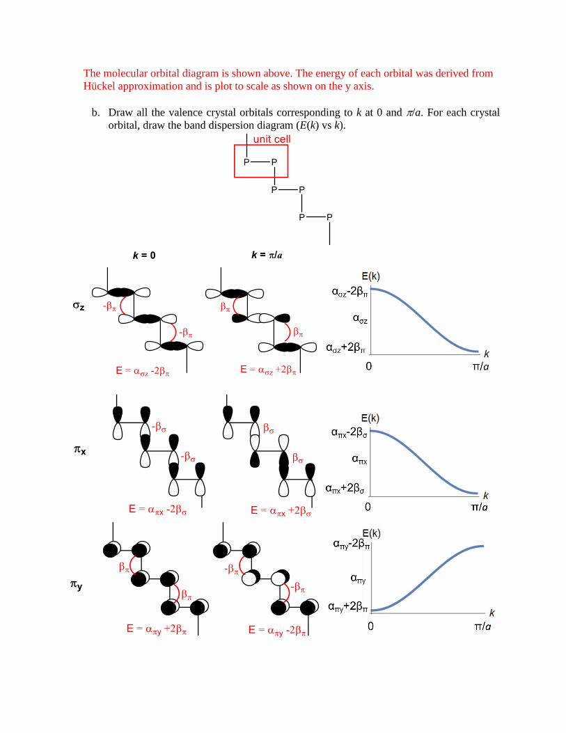
The molecular orbital diagram is shown above. The energy of each orbital was derived from
Hückel approximation and is plot to scale as shown on the y axis.
b. Draw all the valence crystal orbitals corresponding to k at 0 and /a. For each crystal
orbital, draw the band dispersion diagram (E(k) vs k).

c. Based on your crystal orbitals, draw a predicted band structure diagram over the first
Brillouin zone and DOS plot for this structure.
Combine all band dispersion diagrams in (b). In doing so, we derive the energy of each
molecular orbitals from the energy diagram shown in (a):
𝛼𝜎𝑧 = 𝛼 + 𝛽𝜎
𝛼𝜎∗𝑧 = 𝛼 − 𝛽𝜎
𝛼𝜋𝑥 = 𝛼𝜋𝑦 = 𝛼 + 𝛽𝜋
𝛼𝜋∗𝑥 = 𝛼𝜋∗𝑦 = 𝛼 − 𝛽𝜋
The resulting band diagram is shown below

(Note that at k = π/2a, all crystal orbitals feature a node at every other unit cell, and the energy
of each crystal orbital is equal to the energy of the molecular orbitals.)
d. Draw the Fermi level on your band structure and DOS diagrams. Do you expect this
material to be an insulator, semiconductor, or metal?
See the diagram in (c). The Fermi energy is at EF = α as each P2 unit has six electrons to fill
six bands. We fill the whole σz band, and a combination of πx and π*x bands, and a combination
of πy and π*y bands. The DOS plot is shown on the right with total DOS plot in black. Notice
that in this case, the Fermi energy lies at where two bands intersect (πx intersects π*x and πy
intersects π*y), and there are only a few states available at EF. Therefore, we expect this
material to be semimetal.
(Note: don’t worry too much about exact ordering of the bands. Depending on how you draw
the band diagram, your answer may differ from the one shown here)
e. Draw the nearest-neighbor COOP curve for the crystal orbitals generated from the
interaction of σpz molecular orbitals of the P2 unit.

The lowest energy crystal orbitals generated from σz orbitals are π bonding in nature (k =
π/a). They correspond to in-phase overlap between nearest neighbor. Thus the COOP curve
is as depicted.
3. 2D Band Diagram
Consider a 2D square array of metal atoms in the xy plane below
a. Draw the crystal orbitals generated from d(x2-y2) atomic orbitals at the special positions
Γ, X, Y, and M in the first Brillouin zone. For each crystal orbital, identify the type of
the interactions (σ/π/δ and bonding/antibonding). Draw the band diagram with the
Γ→X→M→Γ→Y→M direction on the x axis.
b. Draw the crystal orbitals generated from d(yz) orbitals at the special positions Γ, X, Y,
and M. Identify the type of the interactions, and draw the band diagram with the
Γ→X→M→Γ→Y→M direction on the x axis.
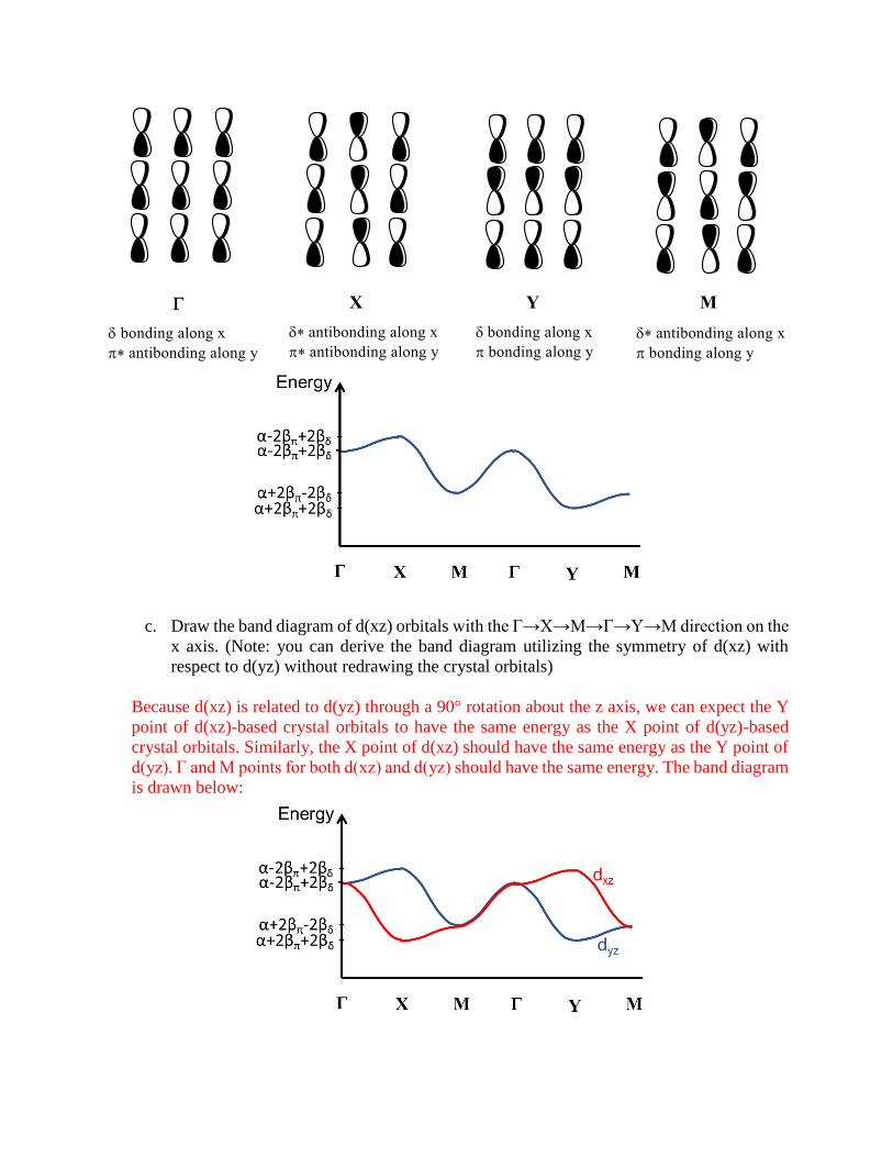
c. Draw the band diagram of d(xz) orbitals with the Γ→X→M→Γ→Y→M direction on the
x axis. (Note: you can derive the band diagram utilizing the symmetry of d(xz) with
respect to d(yz) without redrawing the crystal orbitals)
Because d(xz) is related to d(yz) through a 90° rotation about the z axis, we can expect the Y
point of d(xz)-based crystal orbitals to have the same energy as the X point of d(yz)-based
crystal orbitals. Similarly, the X point of d(xz) should have the same energy as the Y point of
d(yz). Γ and M points for both d(xz) and d(yz) should have the same energy. The band diagram
is drawn below:

The calculated band structures of the following 2D materials are seen below:
d. The valence band is shown in blue and marked with a “V” and the conduction band is
shown in orange and marked with a “C”. For each 2D material, predict whether it is a
metal, semiconductor, or insulator. (Note: the Fermi levels for each material have been
normalized to 0 eV for each plot).
The band gap (Eg) of MoS2 is 1.8 eV, while that of ZrS2 is 1.0 eV. These are measured from
the bottom of the conduction band (C) to the top of the valence band (V). These materials
should behave as semiconductors because their band gaps are small (< 2 eV). NbS2 and PdS2
are metallic because the Fermi energy fall in the middle of the band. It takes very little energy
to excite electrons in the band.
4. Potassium and beryllium are both electrically conductive metals. Rationalize this based on the
basis of the band structure for each of these two elements.
Potassium only has one 4s electron, so it has a half-filled conduction band for solid potassium,
leading to it being a metal since electrons can be conducted through the material. Beryllium
has two 2s electrons and thus a filled band. However, electrical conduction occurs because of
the 2p band overlaps with 2s.
5. Magnetic Properties
a. On an atomic level, what causes a material to be: i) paramagnetic, ii) diamagnetic, iii)
ferromagnetic?
i) Paramagnetism occurs in all materials with unpaired electrons. The magnetic dipole in a
material due to the spin of unpaired electron(s) will orient in the direction of an applied
field.
ii) All materials are inherently diamagnetic, and this arises from the response of the electrons
in a material to an applied magnetic field. The circulation of electrons induced by the
magnetic field in turn induces a small magnetic moment in opposition to the direction of
the applied field (Lenz’s law).
iii) Above the Curie temperature, thermal energy overcomes the preference for ordered
alignment of the spins, and the spin orientations become disordered. When the temperature
is lowered below Tc, exchange interaction between spins can orient all moments in the
same direction, creating a net magnetic moment.
b. Rank i, ii, and iii by the relative magnitude of their magnetic susceptibility.
χ(diamagnetic) < 0 < χ(paramagnetic) < χ(ferromagnetic)
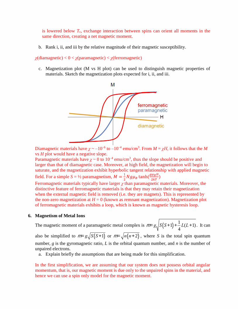
c. Magnetization plot (M vs H plot) can be used to distinguish magnetic properties of
materials. Sketch the magnetization plots expected for i, ii, and iii.
Diamagnetic materials have χ ~ –10–6 to –10–4 emu/cm3. From M = χH, it follows that the M
vs H plot would have a negative slope.
Paramagnetic materials have χ ~ 0 to 10–4 emu/cm3, thus the slope should be positive and
larger than that of diamagnetic case. Moreover, at high field, the magnetization will begin to
saturate, and the magnetization exhibit hyperbolic tangent relationship with applied magnetic
field. For a simple S = ½ paramagnetism, 𝑀 =1
2𝑁𝑔𝜇𝐵 tanh(
𝑔𝜇𝐵𝐻
2𝑘𝑇)
Ferromagnetic materials typically have larger χ than paramagnetic materials. Moreover, the
distinctive feature of ferromagnetic materials is that they may retain their magnetization
when the external magnetic field is removed (i.e. they are magnets). This is represented by
the non-zero magnetization at H = 0 (known as remnant magnetization). Magnetization plot
of ferromagnetic materials exhibits a loop, which is known as magnetic hysteresis loop.
6. Magnetism of Metal Ions
The magnetic moment of a paramagnetic metal complex is m = g S S+1( ) +1
4L(L+1) . It can
also be simplified to m = g S S+1( ) or m = n n+2( ) , where S is the total spin quantum
number, g is the gyromagnetic ratio, L is the orbital quantum number, and n is the number of
unpaired electrons.
a. Explain briefly the assumptions that are being made for this simplification.
In the first simplification, we are assuming that our system does not possess orbital angular
momentum, that is, our magnetic moment is due only to the unpaired spins in the material, and
hence we can use a spin only model for the magnetic moment.

In the second expression, we are using n, the total number of unpaired electrons, rather than
the total spin S. These two expressions are really the same, then, and the only simplification
is that we are assuming the g value to be 2 (the actual value is 2.002320(4)). This a good
assumption to use when considering a spin-only system.
b. Give an example of a substance that do not follow this simplified magnetic moment
expression
Substances of which their electrons possess orbital angular momentum will deviate from this
expression. Lanthanide ions (Ln3+) are the typical examples of such substances because the f
electrons are shielded from the environment and therefore f electrons behave as if they are in
a free ion with unquenched orbital angular momentum.
c. Complete the following table (assume g = 2):
Free Ion # unpaired electrons Total spin (S) Spin-only magnetic moment (s)
Mn2+ 5 (d5) 5/2 5.92
Fe+ 3 (d7) 3/2 3.87
Gd3+ 7 (f7) 7/2 7.94
d. If placed in the octahedral holes of a solid oxide lattice, which (if any) of these metal ions
in (c) would be expected to have moments that deviate from the free ion value and why?
Magnetic moment of a free ion is calculated using the expression 𝜇 =
𝑔√𝑆(𝑆 + 1) +1
4𝐿(𝐿 + 1) . This takes into account the orbital angular momentum of the
electrons. This is not the case for Fe+ ions (d7) when it is placed in the octahedral holes, because
the oxide ligands will quench L, giving rise to spin-only magnetic moment. Mn2+ (d5) and Gd3+
(f7) ions have half filled d/f orbitals and do not possess orbital angular momenta (L = 0) even
in the free ion states. Therefore, we don’t expect the magnetic moment to deviate from the
predicted value. Typically, if we place other lanthanide ions in the ligand field, they would
have magnetic moments deviating from spin-only values because the orbital angular
momentum is not quenched.
e. Partial substitution of Fe(I) ions into Li3N matrix resulted in a crystalline solid with the
formula Li2(Li1-xFex)N (x = 0.28). Li2(Li1-xFex)N crystallizes in a hexagonal space group,
with the structure shown below. Dark blue spheres represent the two-coordinate sites of
Li+ which are partially substituted by Fe+ ions.

The effective magnetic moment for this solid is 6.5 μB per Fe ion (measured along c axis).
What might be the reason for the magnetic moment of this material to deviate from the
value you predicted in (c)?
The magnetic moment of this material is much higher than the 3.87 µB per Fe(I) ion value
expected. This can be rationalized by invoking orbital angular momentum (L) contribution to
the magnetic moment. Because of the special coordination environment, the Fe(I) ions assume
a linear two-coordinate geometry. This geometry allows the electrons to orbit around the Fe
nucleus about the c axis of the crystal, and prevents Jahn-Teller distortion (such distortion
mode is not possible in two-coordinate metal centers). This gives rise to a special scenario
where the orbital angular momentum of a transition metal ion is not quenched in a material.
f. An organometallic complex Co(II)L4 has a magnetic moment of µ= 1.73µB. Is it more
likely to have a square planar or tetrahedral coordination geometry?
With Co(II) complex, it is sufficient to use the spin-only expression for the magnetic moment.
Tetrahedrally coordinated Co(II) will have S = 3/2, and thus = 3.87 µB. Square planar
coordination geometry, on the other hand, would yield S = 1/2 and therefore = 1.73 µB, which
is in agreement with experiment. This is because d(x2-y2) orbital in square planar complex is
very high in energy due to ligand destabilization.
7. Magnetite
The mineral magnetite is the most magnetic naturally occurring material. It has the spinel
structure type (AB2O4) where A (tetrahedral holes) sites are occupied by Fe3+ and B (octahedral
holes) sites are equally occupied by Fe3+ and Fe2+ ions.
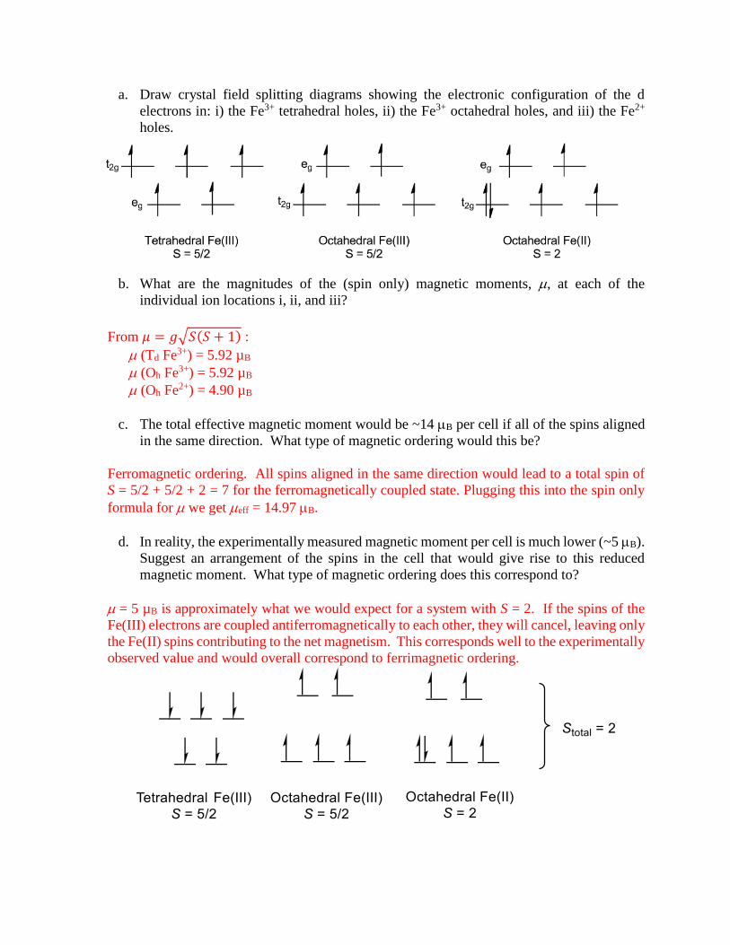
a. Draw crystal field splitting diagrams showing the electronic configuration of the d
electrons in: i) the Fe3+ tetrahedral holes, ii) the Fe3+ octahedral holes, and iii) the Fe2+
holes.
b. What are the magnitudes of the (spin only) magnetic moments, , at each of the
individual ion locations i, ii, and iii?
From 𝜇 = 𝑔√𝑆(𝑆 + 1) :
(Td Fe3+) = 5.92 µB
(Oh Fe3+) = 5.92 µB
(Oh Fe2+) = 4.90 µB
c. The total effective magnetic moment would be ~14 B per cell if all of the spins aligned
in the same direction. What type of magnetic ordering would this be?
Ferromagnetic ordering. All spins aligned in the same direction would lead to a total spin of
S = 5/2 + 5/2 + 2 = 7 for the ferromagnetically coupled state. Plugging this into the spin only
formula for we get eff = 14.97 B.
d. In reality, the experimentally measured magnetic moment per cell is much lower (~5 B).
Suggest an arrangement of the spins in the cell that would give rise to this reduced
magnetic moment. What type of magnetic ordering does this correspond to?
= 5 µB is approximately what we would expect for a system with S = 2. If the spins of the
Fe(III) electrons are coupled antiferromagnetically to each other, they will cancel, leaving only
the Fe(II) spins contributing to the net magnetism. This corresponds well to the experimentally
observed value and would overall correspond to ferrimagnetic ordering.

8. Single-Molecule Magnet
The discovery that individual molecules could display similar magnetic properties to bulk
magnets, such as magnetic hysteresis, came about from the study of the first single molecule
magnet in 1993. This dodecanuclear manganese cluster has the formula
Mn12O12(O2CMe)16(H2O)4, and the core structure of the molecule is shown below. Four central
MnIV ions (large gray spheres) are surrounded by eight MnIII ions (large white spheres), and
the Mn ions are connected through bridging oxide ligands. Significantly, this molecule was
found to have an overall S = 10 ground state and to display magnetic hysteresis below 4 K.
a. Predict the magnetic moment of this molecule
Assuming g = 2 for this complex,
𝜇 = 𝑔√𝑆(𝑆 + 1) = 2√10(10 + 11) = 20.98 µB
b. Rationalize the total ground state molecular spin (S = 10) based on the individual spins
of each manganese ion and relevant magnetic interactions.
This molecule consists of four Mn(IV) ions (S = 3/2) and eight Mn(III) ions (S = 3/2). If all spins
are coupled ferromagnetically, they would yield a molecular spin S = 4(3/2) + 8(2) = 22, which is
not the case experimentally observed. To get S = 10, the four Mn(IV) centers have to couple
antiferromagnetically to the eight Mn(III) centers: S = –4(3/2) + 8(2) = 10.
In this case, the four Mn(IV) ions are coupled ferromagnetically to one another, and
antiferromagnetically to the eight Mn(III) ions. See the illustration:

c. What mechanism promotes the magnetic interaction between MnIII and MnIV in this
molecule?
The Mn(III) and Mn(IV) centers are magnetically coupled through superexchange interactions
through bridging oxo ligands.


![CS 231A Computer Vision, Winter 2015 Problem Set 1...CS 231A Computer Vision, Winter 2015 Problem Set 1 Due Date: Jan 28th 2015 11:59 pm 1Some Projective Geometry Problems [15 points]](https://img.dokumen.tips/doc/110x75/5f2f162ea53dd039fc66dcc6/cs-231a-computer-vision-winter-2015-problem-set-1-cs-231a-computer-vision.jpg)


![GFD I Problem Set 4 Solutions - UW Faculty Web Server...1 GFD I, Solutions for Problem Set #4, 2/29/2012 [30 points total] For reference, the governing equations for this problem are:](https://img.dokumen.tips/doc/110x75/5fe867dea7a74936672837a4/gfd-i-problem-set-4-solutions-uw-faculty-web-server-1-gfd-i-solutions-for.jpg)


