Embed Size (px)
Citation preview

General rights Copyright and moral rights for the publications made accessible in the public portal are retained by the authors and/or other copyright owners and it is a condition of accessing publications that users recognise and abide by the legal requirements associated with these rights.
Users may download and print one copy of any publication from the public portal for the purpose of private study or research.
You may not further distribute the material or use it for any profit-making activity or commercial gain
You may freely distribute the URL identifying the publication in the public portal If you believe that this document breaches copyright please contact us providing details, and we will remove access to the work immediately and investigate your claim.
Downloaded from orbit.dtu.dk on: Feb 05, 2022
Chemical herding of weathered crude oils for in-situ burning
Rojas-Alva, Ulises; Andersen, Bjørn Skjønning; Jomaas, Grunde
Published in:Journal of Environmental Management
Link to article, DOI:10.1016/j.jenvman.2019.109470
Publication date:2019
Document VersionPeer reviewed version
Link back to DTU Orbit
Citation (APA):Rojas-Alva, U., Andersen, B. S., & Jomaas, G. (2019). Chemical herding of weathered crude oils for in-situburning. Journal of Environmental Management, 250, [109470]. https://doi.org/10.1016/j.jenvman.2019.109470

1
Chemical herding of weathered crude oils for in-situ burning
U. Rojas Alvaa,b, Bjørn Skjønning Andersena, Grunde Jomaasa,b
aCivil Engineering Department, Technical University of Denmark, Denmark
bSchool of Engineering, BRE Centre for Fire Safety Engineering, The University of
Edinburgh, United Kingdom
Abstract
Mid-scale ISB experiments were conducted in a large water-basin (20 m2 x 1 m) in order to
assess the applicability of chemical herding of weathered crude oil spills on water in association
with in-situ burning (ISB). A silicone-based chemical herding agent, OP-40, was used to
confine, or herd, three different crude oils (Siri, Grane and Oseberg blend) at various
weathering degrees. The herding agent was capable of obtaining the minimum required oil
slick thickness for ignition and subsequent flame spread in most of the experiments, but not for
the strongly weathered oils. Also, the herding agent was capable of re-thickening the oil slick
after flame extinction. The burning efficiency results indicate that the method can be viable for
ISB with herders at a larger scale, and suggest that the burning efficiency scales with the
amount of crude oil. Sinking behaviour of residues was also observed and quantified, as such
a behaviour can pose a serious environmental threat in real scenarios.
Keywords: Oil spill, Herding, Burning efficiency, regression rate, pollution
1. Introduction
Spillage of crude oil in Arctic and Antarctic waters has become a crucial issue for fragile local
environments. There is an increasing concern from governments and private companies over
the occurrence and impact of oil spills in the sea and its efficient removal. Due to global
warming, over the last decade, there has been a reduction of ice-presence in the Arctic and a
reduction of average sailing times through the various shipping routes. As a consequence, the
Arctic shipping routes are experiencing increasing pressure on cargo transportation (Aksenov
et al., 2017). In addition, there is also an increasing pressure of cruise ship activity in the
Antarctic waters and an increase of oil spills from vessels has been reported (Filler et al., 2015).
Further to this, Norway has recently announced the exploitation of their oil reserves under the
Barents Sea where several wells are going to be drilled. Other countries with territorial waters
in the Arctic sea are expected to commence with similar activities. The occurrence of oil spills
2
due to the breakup of pipelines or wells and vessels are apparent. A well-known example of
how devastating such an event can be is the Deepwater Horizon oil spill in the Gulf of Mexico
(The Federal Interagency Solutions Group, 2010). Oil spills in cold regions waters have also
been reported (Filler et al., 2015).
There are various cleaning methods to remove the oil spill from open waters, such as
mechanical extraction, chemical dispersion, in-situ burning among others (Fingas, 2011a;
Nuka, Research & Planning Group, 2010). In-situ burning (ISB) is an on-site burning of an oil
spill that allows the conversion of the oil hydrocarbon components into combustion products
such as carbon monoxide, soot, and other gases that are released to the atmosphere (Buist et
al., 2013). This technique has been proven to be effective for large oil spills (Bech et al., 1992;
Shi et al., 2016). In the Arctic context, ISB was identified as the most effective solution (due
to remoteness and ice-infested waters) (Bullock et al., 2019; Fritt-Rasmussen et al., 2012; Shi
et al., 2016; Van Gelderen et al., 2015). In fact, various studies have reported that more than
90% of an oil spill can be removed using in-situ burning (Aggarwal et al., 2017; Buist et al.,
2011, 2013; Buist and Twardus, 1985; Fingas et al., 1995; Van Gelderen et al., 2015).
Once the oil is spilled over the sea, it expands and decreases in thickness owing to the sea and
climatological conditions. To successfully achieve in-situ burning, i.e., to achieve ignition and
subsequent burning of the crude oil, a minimum oil slick thickness is necessary (Nordvik et al.,
2003). Confinement, either mechanical or chemical, is needed to maintain a minimum oil slick
thickness throughout the burning process. Mechanical confinement requires fire-resistant
booms (barriers) deployed and managed by vessels. This technique can prove challenging in
the Arctic and Antarctic waters due to remoteness and the presence of drifting-ice. It is worth
noting that physical confinement can also occur naturally, e.g., in ice cavities, due to the wind,
between ice blocks (Aggarwal et al., 2017; Dickins et al., 2008; Energetex Engineering, 1981;
Fritt-Rasmussen and Brandvik, 2011).
Chemical confinement presents advantages over the mechanical option. The chemical agents
used for chemical confinement are commonly known as “herders”. These chemical herders
push the oil due to the difference in surface tension between the oil and the monolayer created
by herder surrounding the oil (Buist et al., 2008a, 2011, 2013). Using chemical herding agents
has shown promising results in achieving large oil removal rates or burning efficiencies (BE)
for the in-situ burning method in the Arctic and Antarctic conditions alike (Buist et al., 2011;
Buist and Potter, 2010; Dickins et al., 2008). Currently, two herding agents are listed in the
U.S. Environmental Protection Agency NCP Product Schedule (Nedwed et al., 2012). These
herding agents are the hydrocarbon-based formulation ThickSlick 6535 (TS6535), and the
silicone-based herder, OP-40 (Lane et al., 2012). Recent studies have shown that OP-40 has
better herding capabilities than TS6535 for fresh-crude oils (Aggarwal et al., 2017; Buist et al.,
2009; Bullock et al., 2017; Potter et al., 2016; van Gelderen et al., 2016).
When spilled on open waters, the crude oil immediately undergoes a weathering process that
depends on many variables (Brandvik and Faksness, 2009; Fritt-Rasmussen et al., 2012; Garo
et al., 2004). Two of the most relevant weathering processes are evaporation (the crude oil’s
lighter components evaporate) and emulsification (the oil mixes with water due to wave action)
(Brandvik and Faksness, 2009; Buist et al., 2013). The degree of evaporation and the content
of specific components in the crude oil, asphaltenes and resins, support the formation and
stability of water-in-oil emulsion (Fingas and Fieldhouse, 2015). The stability degree of
emulsification determines the ignitability of an emulsified crude oil (Buist et al., 2013). That
is, for more stable emulsions (due to the higher content of water), it will be nearly impossible
to ignite and develop flame spread. Thus, the weathering will influence the overall burning
behaviour of the spilled oil during ISB (Fritt-Rasmussen et al., 2012; Fritt-Rasmussen and
3
Brandvik, 2011; Guénette et al., 1995). Consequently, in a remote location (such as in the
Arctic), the ISB responders are quite likely to encounter a weathered crude oil. Previous ISB
studies with herders have mainly focused on fresh crude oils (Aggarwal et al., 2017; Buist et
al., 2007, 2008a, 2010, 2011, 2017; Bullock et al., 2017; Rojas Alva et al., 2018; Singsaas et
al., 2017; van Gelderen et al., 2016). However, little is known about its ability to thicken
weathered or emulsified crude oils for in-situ burning.
The burning efficiency has been found to show discrepancies as a function of the oil slick size,
especially in small-scale laboratory experiments (Buist, 2006; Buist et al., 2008a, 2011). One
reason for this is that boilover (sudden splash of waterbed under the fuel due to nucleation of
water) has been reported to disrupt the burning during ISB in small-scale experiments
(Brogaard et al., 2014; Evans et al., 2001; Rojas Alva et al., 2018; Van Gelderen et al., 2015).
In large-scale and more realistic operational scenarios (in open waters), boilover has not been
observed according to literature. Consequently, it is difficult to extrapolate the burning
behaviour from small-scale (environment/experiments) testing to more-realistic scenarios.
Based on the findings and knowledge gaps presented above, two objectives were set for the
current study. The first objective was to study the thickening effectiveness of the silicone
herding agent on various weathered crude oils before and during burning. The second objective
was to study the burning behaviour of the chemically herded crude oils during and after ISB.
For the latter, two ISB specific parameters were estimated, namely the burning efficiency (BE)
and the regression rate. In addition, the sinking behaviour of the post-burn residues was
observed.
2. Methodology
For this study, various amounts (1.6 to 25 l.) of three artificially weathered crude oils (Siri,
Grane and Oseberg Blend) were selected and the silicone-based herding agent (OP-40) was
used. The mid-scale experiments were conducted in a large water basin (20 m2) in the outdoors,
see Figure 1, to avoid boilover and to produce a small oil-to-water ratio, thus recreating realistic
scenarios.
Figure 1 - The mid-scale experimental set-up. The left schematic shows a top view and the
right schematic a side-view. Dimensions are in mm.
Three crude oils were chosen for this study; these were Grane, Oseberg blend and Siri. Grane
(Norway) is an asphaltenic crude oil, rich in resins and asphaltenes. The density of Grane crude
oil is high, and the evaporative loss is low (Brandvik et al., 2010; Fritt-Rasmussen, 2010).
Oseberg is a blend of crude oil from the Oseberg, Brage and Veslefrikk fields (Norway).
Oseberg blend is a light, intermediate low-sulphur North Sea crude oil similar in quality to
4
Brent (ExxonMobil, 2018). Siri (Danish) is paraffinic crude oil with a high content of waxy
components and medium evaporative losses. Grane and Siri oils are representative of two of
the four groups of crude oils categorized by SINTEF. However, the Oseberg blend cannot be
tentatively categorized because relevant data has not been found in the literature. The physical
properties of the crude oils are listed in Table 1.
Table 1 – Physical properties of the fresh crude oils and the herding agent. All of the properties
were extracted from the corresponding MSDS sheets.
Oil/
Herder
Asphaltene
content
[wt %]
Paraffin
content
[wt %]
Naphthene
content
[wt %]
Density at
15.5 °C
[g/cm3]
Pour
point
[°C]
Viscosity at
20 °C
[mPas]
Flash-
point [°C]
Grane 0.9 24.6 37.3 0.89 1.3 23.1 20-21
Siri 0.35 0.84 9 10
Oseberg blend 0.2 36.5 40.1 0.83 -15 4.1 -24
OP40 0.99 23.4 10-40 >100*
The herding agent used in the experiment (OP-40) is silicone-based with high thermal stability
and behaves like a liquid at room temperature, and it is a standard silicone copolymer, which
is considered a non-ionic amphiphilic copolymer (Kunieda et al., 2001). OP-40 can be found
in common applications (cleaning products, hair condition, etc.). Table 1 lists the physical
properties of OP-40 and further information can be found in (Rojas-Alva et al., 2019a).
The experimental matrix for the study presented herein is displayed in Table 2. The Grane
crude oil was only tested in fresh conditions for two amounts, 1.6 and 20 litres, as it served as
a benchmark for comparison with previously reported results (Buist et al., 2017; Rojas-Alva et
al., 2019a). The Siri crude oil was only subjected to evaporation at a degree of 15%, and various
amounts were employed in the experiments (from 2 to 25 litres). The Oseberg blend was
evaporated at two degrees (25 and 40%) and evaporated at 40% combined with an
emulsification degree of 40% water content, see Figure 2. For the evaporated Oseberg blend,
intermediate amounts were used in the experiments (7 to 14 litres). Lastly, a strongly weathered
Oseberg blend, evaporated at >40% and emulsified at 50% (water content), was tested at large
quantities (25 litres). This Oseberg blend was weathered at SINTEF SeaLab in Trondheim.
Table 2 – Experimental matrix indicating the test conditions as a function of the evaporation
degree and water content (*weathered Oseberg blend provided by SINTEF).
Oil type Evaporation degree [%] Water content [%]
Grane 0 0
Siri 15 0
Oseberg blend 25 and 40 0 and 40
Oseberg blend* >40 50
For this study, the crude oils were artificially evaporated and emulsified to various degrees
with the aim of reproducing the scenarios when an oil spill occurs. The evaporation of the crude
oils was done by injecting air bubbles from a pressurized vessel to the bottom of a container
with the crude oil. The artificial evaporation method used for this experimental study has been
used in previous investigations (Buist et al., 2008b; Buist and Glover, 1995; Opstad and
Guénette, 2000; S.L. Ross Environmental Research Ltd., 2007). The method was carried out
until the desirable evaporation degree was obtained. The crude oil was mixed with artificial
sea-water (32 ‰ salinity) to emulsify the crude oil (evaporated). A tank containing both the

5
crude oil and the sea-water was placed on a shaking table for 24 hours at 190 rpm. The density
and viscosity of all fresh and evaporated crude oils are listed in Table 3.
Table 3 – Physical properties of the weathered crude oils. The densities and viscosities were
determined by the Paar Stabinger Viscometer SVM 3000 apparatus*.
Oil Evaporation
degree [%]
Water
content [%]
Density at
25 °C [g/cm3]
Viscosity at 25
°C [mPas]
Siri 15 0 0.88 20
Oseberg blend
25 0 0.86 11
40 0 0.87 19
40 40 0.95 99
Oseberg blend
(SINTEF) >40 50 0.97 622
*The viscometer follows various standards for measuring kinematic viscosities (ASTM D7042,
EN16896, and DIN 51659-2) and the density (EN ISO 12185, ASTM D4052, and IP 365).
For each experiment, the weathered crude oil was poured onto the water basin and left to spread
for 30 minutes. Thereafter, 150 µl of the herding agent OP-40 was applied per m2 of surface
water, as this is the recommended operational dose (Buist et al., 2017, 2011, 2009; van
Gelderen et al., 2016). It was applied from the edge of the basin to thicken the oil slick centrally.
During the herding process, a camera placed above the water basin was used to estimate the oil
slick area (and hence thickness) and flame areas, see Figure 1. In some of the experiments, the
water was pre-treated with the herding agent (before the oil was poured) to minimize the
influence of wind and to optimise the number of experiments.
After the herding procedure was completed, an igniter promoter made of gelled gasoline-diesel
mixture was added before ignition with a torch. For most of the cases, a small amount of the
igniter promoter was used. If the first amount of igniter promoter did not succeed to ignite the
oil slick, an increased amount of igniter was used in a second attempt, and so on for a third
attempt.
Before conducting an experiment, the air velocity was measured by an anemometer, which
measured wind speeds of less than 5 m/s (see Table 4 in Section 3.2), which is below the critical
operational wind velocity (Buist et al., 2013; Fingas, 2011b; Potter and Buist, 2008).
2.1. Estimation of parameters
The herding effectiveness was analysed through the herder capability to thicken the oil slick to
a sufficient thickness to attain ignition during the time prior to ignition (<35 min). Therefore,
the measurement of the oil slick thickness during the herding procedure was required. By
knowing the initial oil/emulsion weight and the density, the oil slick thickness could readily be
estimated using the oil slick area from the recorded images.
During combustion, the properties of the oil and the oil mass will change over time (van
Gelderen et al., 2017), and therefore it is impossible to estimate an oil slick thickness. Hence,
the herding effectiveness after during burning was analysed through the estimation of the oil
slick area along with the area of the oil slick covered by flames.
The burning behaviour of the fresh and weathered crude oils of various sizes was evaluated
through two burning-related parameters, the burning efficiency (BE) and the regression rate
(�̇�′′). The first indicates the mass of crude oil burnt during the ISB experiment. Large BE is

6
indicative of a significant ratio removal success of spilled crude oil. The burning efficiency can
be estimated by using the following expression:
𝐵𝐸 [%] =𝑚0 −𝑚𝑓
𝑚0100 Equation 1
Where 𝑚0 and 𝑚𝑓 are the initial mass [kg] and the final mass of the crude oil, respectively. For
the case of emulsified crude oil, only the corresponding oil mass in the emulsion was
considered to estimate the BE. For each burning experiment, the post-burnt oil residue was
collected in oil-sorbent and hydrophobic pads that were dried out in an industrial oven for 24
hours to remove the excess of water. Thus, the final mass of oil (𝑚𝑓) was estimated for all
experiments.
The second parameter, the burning rate (�̇�′′), expresses the burning per unit time or thickness
deployment in time and it is a useful parameter for in-situ operations. There are various
manners to estimate the mass burning rate or regression rate. For this study, the method based
on the maximum area coverage was used by applying the following equation (Buist et al.,
2011):
�̇�′′ [𝑚𝑚 𝑚𝑖𝑛]⁄ =𝐵𝐸 ∗ 𝑉𝑜
𝑆𝑜𝑖𝑙𝐴𝑓,𝑚𝑎𝑥(𝑡𝑒𝑥𝑐,50% − 𝑡𝑖𝑔,50%) Equation 2
Where 𝑉𝑜 is the initial oil volume [l], 𝑆𝑜𝑖𝑙 is the oil slick area [m²], 𝐴𝑓,𝑚𝑎𝑥 is the maximum
percentage coverage of the flame over the oil slick, 𝑡𝑒𝑥𝑐,50% is the time when the flame area
has decreased to 50% of the slick area [min], and 𝑡𝑖𝑔,50% is the time when 50% of the slick area
is covered by flames [min]. Most of the area and times were obtained from the video recording
during the burning experiments.
3. Results and discussion
3.1. Herding effectiveness
3.1.1. Herding effectiveness before ignition
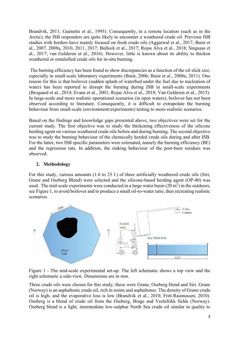
The herding efficiency of OP-40 as a function of time for the different crude oils at various
weathering conditions is depicted in Figure 2. The first measurement of the oil slick thickness
was taken as the application of the herding agent, and the span of the herding experiments
varied from test to test (from 16 to 37 min). During each experiment, the herding agent was
carefully poured in order to maintain the oil slick located away from the walls.
7
Oil Symbol Herder
treatment
Size
[l.]
Evaporation
Degree [%]
Water
Content
[%]
Oil Symbol Herder
Treatment
Size
[l.]
Evaporation
Degree [%]
Water
Content
[%]
Grane
Post 1.6
0 0 Oseberg
Post 10 25 0
Post 20 Pre 7 40 0
Post 20 Post 10
Siri
Pre 2 15 0 Oseberg
(SINTEF)
Pre 26
>40 50 Post 4 Post 25
Oseberg
Post 4
40 40
Post 25
Pre 7.5
Pre 14
Post 15
Figure 2 – Oil slick thickness as a function of time for Grane, Siri and Oseberg crude oil under
various weathered conditions.
The results corresponding to three experiments with fresh Grane can be seen in Figure 2A. The
oil amount was 1.6 litres in one experiment, and 20 litres in the other two. In all the three cases,
the herding agent thickened the fresh Grane crude oil slick relatively fast (i.e. within the first
five to eight minutes), so that a stable 8 mm slick thickness was reached. No decay in thickness
was observed for the duration of the test. Similar thicknesses or slightly lower thicknesses were
reported by Buist et al., who used shallow pans of various sizes (Buist et al., 2017). In their
work, they also reported a decay in oil slick thickness for fresh Grane with OP-40. This
difference in behaviour might be attributed to the experimental conditions (e.g. indoor lab,
extraction, and re-radiation) and the length of the test (60 minutes and longer). The results from
Grane are qualitatively similar small-scale experiments reported by Rojas-Alva et al. (Rojas-
Alva et al., 2019a). However, the current Grane results are 2 mm greater than those reported
by Rojas-Alva et al. (Rojas-Alva et al., 2019a), who suggested that the difference was a result
of differences in the initial oil slick thickness before herding. In their work, their experiments
had an initial oil slickness (after reaching equilibrium) less than 0.5 mm, whereas the initial oil
slick thickness was much greater (around 2 mm) in the current study.
0
2
4
6
8
10
0 5 10 15 20 25 30
Sli
ck
th
ick
ness
[m
m]
Time [min]
B
Oseberg/40% (7 l.)
Oseberg/40% (10 l.)
Oseberg/25% (10 l.)
0
2
4
6
8
10
0 5 10 15 20 25 30
Sli
ck
th
ick
ness
[m
m]
Time [min]
C
(4 l.)
(4 l.)
(14 l.)
(15 l.)
Oseberg/40%/40%0
2
4
6
8
10
12
14
0 5 10 15 20 25 30 35 40
Sli
ck
th
ick
ness
[m
m]
Time [min]
DOseberg (SINTEF)
(26 l.)
(25 l.)
(25 l.)
0
2
4
6
8
10
0 5 10 15 20 25 30
Sli
ck
th
ick
ness
[m
m]
Time [min]
A
Grane (1.6 l.)
Siri/15% (2 l.)
Siri/15% (4 l.)
Grane (20 l.)
Grane (20 l.)
02468
10
0 5 10 15 20 25 30
Sli
ck
th
ick
ness
[m
m]
Time [min]
1.55 L.20 L. (trial 1)20 L. (trial 2)2 L.Series1
A
Grane (1.6 l.)
Siri/15% (2 l.)Siri/15% (4 l.)
Grane (20 l.)
Grane (20 l.)02468
10
0 5 10 15 20 25 30
Sli
ck
th
ick
ness
[m
m]
Time [min]
10 L.7 L.10 L.
BOseberg/40% (7 l.)
Oseberg/40% (10 l.)
Oseberg/25% (10 l.)
02468
10
0 5 10 15 20 25 30
Sli
ck
th
ick
ness
[m
m]
Time [min]
1.55 L.20 L. (trial 1)20 L. (trial 2)2 L.Series1
A
Grane (1.6 l.)
Siri/15% (2 l.)Siri/15% (4 l.)
Grane (20 l.)
Grane (20 l.)
02468
101214
0510152025303540
Sli
ck
th
ick
ness
[m
m]
Time [min]
26 L. (trial 1)25 L. (trial 2)25 L. (trial 3)
D
Oseberg (SINTEF)
(26 l.)
(25 l.)
(25 l.)
02468
10
0 5 10 15 20 25 30
Sli
ck
th
ick
ness
[m
m]
Time [min]
4 L.7.5 L.14 L.15 L.
C(4 l.)
(4 l.)
(14 l.)
(15 l.)
Oseberg/40%/40%
8
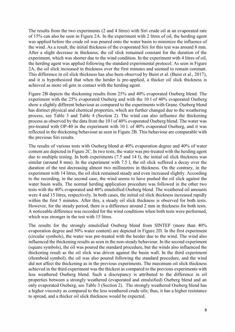
The results from the two experiments (2 and 4 litres) with Siri crude oil at an evaporated rate
of 15% can also be seen in Figure 2A. In the experiment with 2 litres of oil, the herding agent
was applied before the crude oil was poured onto the water basin to minimize the influence of
the wind. As a result, the initial thickness of the evaporated Siri for this test was around 8 mm.
After a slight decrease in thickness, the oil slick remained constant for the duration of the
experiment, which was shorter due to the wind condition. In the experiment with 4 litres of oil,
the herding agent was applied following the standard experimental protocol. As seen in Figure
2A, the oil slick increased in thickness over the first minutes and seemed to remain constant.
This difference in oil slick thickness has also been observed by Buist et al. (Buist et al., 2017),
and it is hypothesized that when the herder is pre-applied, a thicker oil slick thickness is
achieved as more oil gets in contact with the herding agent.
Figure 2B depicts the thickening results from 25% and 40% evaporated Oseberg blend. The
experiment with the 25% evaporated Oseberg and with the 10 l of 40% evaporated Oseberg
show a slightly different behaviour as compared to the experiments with Grane. Oseberg blend
has distinct physical and chemical properties, which are further changed due to the weathering
process, see Table 3 and Table 4 (Section 2). The wind can also influence the thickening
process as observed by the data from the 10 l of 40% evaporated Oseberg blend. The water was
pre-treated with OP-40 in the experiment with 10 l. of 40% evaporated Oseberg, and it was
reflected in the thickening behaviour as seen in Figure 2B. This behaviour are comparable with
the previous Siri results.
The results of various tests with Oseberg blend at 40% evaporation degree and 40% of water
content are depicted in Figure 2C. In two tests, the water was pre-treated with the herding agent
due to multiple testing. In both experiments (7.5 and 14 l), the initial oil slick thickness was
similar (around 8 mm). In the experiment with 7.5 l, the oil slick suffered a decay over the
duration of the test decreasing almost two millimetres in thickness. On the contrary, in the
experiment with 14 litres, the oil slick remained steady and even increased slightly. According
to the recording, in the second case, the wind seems to have pushed the oil slick against the
water basin walls. The normal herding application procedure was followed in the other two
tests with the 40% evaporated and 40% emulsified Oseberg blend. The weathered oil amounts
were 4 and 15 litres, respectively. In both cases, the initial oil slick thickness increased rapidly
within the first 5 minutes. After this, a steady oil slick thickness is observed for both tests.
However, for the steady period, there is a difference around 2 mm in thickness for both tests.
A noticeable difference was recorded for the wind conditions when both tests were performed,
which was stronger in the test with 15 litres.
The results for the strongly emulsified Oseberg blend from SINTEF (more than 40%
evaporation degree and 50% water content) are depicted in Figure 2D. In the first experiment
(circular symbols), the water was pre-treated with the herder due to the wind. The wind also
influenced the thickening results as seen in the non-steady behaviour. In the second experiment
(square symbols), the oil was poured the standard procedure, but the winds also influenced the
thickening result as the oil slick was driven against the basin wall. In the third experiment
(rhomboid symbol), the oil was also poured following the standard procedure, and the wind
did not affect the thickening as in the previous experiments. The maximum oil slick thickness
achieved in the third experiment was the thickest as compared to the previous experiments with
less weathered Oseberg blend. Such a discrepancy is attributed to the difference in oil
properties between a strongly weathered (evaporated and emulsified) Oseberg blend and an
only evaporated Oseberg, see Table 3 (Section 2). The strongly weathered Oseberg blend has
a higher viscosity as compared to the less weathered crude oils; thus, it has a higher resistance
to spread, and a thicker oil slick thickness would be expected.
9
Overall, in all cases, the herding agent OP-40 was capable of thickening the oil slick of the
fresh and the weathered crude oils. The herding agent OP-40 was successful in achieving the
minimum oil slick thickness (1 mm) for fresh and weathered crude oil (Buist et al., 2013)
needed for a successful ignition. Despite the fact that the wind had an obvious impact on the
evolution of the oil slick thickness, the herding agent OP-40 was still capable of performing
well in such scenarios. The wind conditions recorded for all tests during the herding experiment
are listed in Table 4 in Section 3.2. Additionally, the herding results for the other two tests with
15% evaporated Siri oil are not presented. During the recording for this experiments, the
camera failed to function in one of the tests, and in the other case the camera was not properly
located and did not record the experiments.
3.1.2. Herding effectiveness during burning
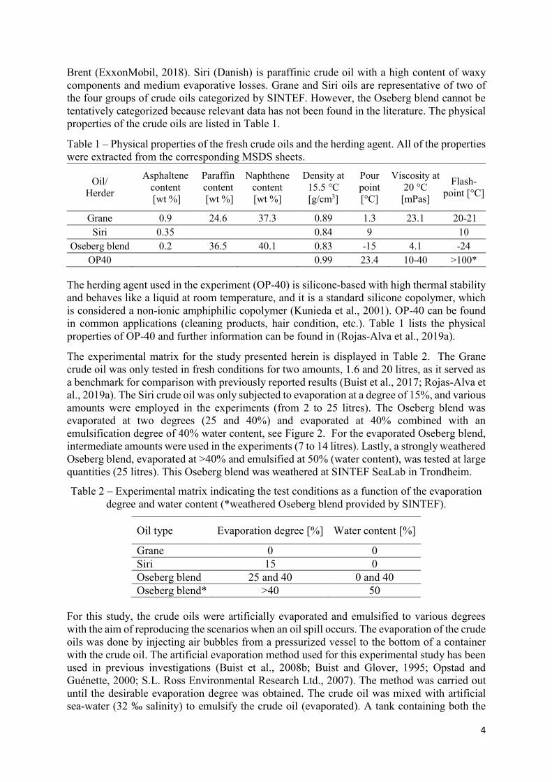
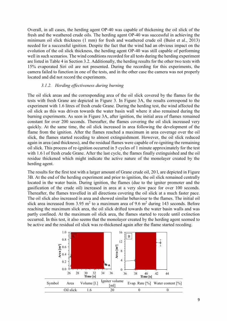
The oil slick areas and the corresponding area of the oil slick covered by the flames for the
tests with fresh Grane are depicted in Figure 3. In Figure 3A, the results correspond to the
experiment with 1.6 litres of fresh crude Grane. During the herding test, the wind affected the
oil slick as this was driven towards the water basin wall where it also remained during the
burning experiments. As seen in Figure 3A, after ignition, the initial area of flames remained
constant for over 200 seconds. Thereafter, the flames covering the oil slick increased very
quickly. At the same time, the oil slick increased in area following the development of the
flame from the ignition. After the flames reached a maximum in area coverage over the oil
slick, the flames started receding to almost extinguishment. However, the oil slick reduced
again in area (and thickness), and the residual flames were capable of re-igniting the remaining
oil slick. This process of re-ignition occurred in 5 cycles of 1 minute approximately for the test
with 1.6 l of fresh crude Grane. After the last cycle, the flames finally extinguished and the oil
residue thickened which might indicate the active nature of the monolayer created by the
herding agent.
The results for the first test with a larger amount of Grane crude oil, 20 l, are depicted in Figure
3B. At the end of the herding experiment and prior to ignition, the oil slick remained centrally
located in the water basin. During ignition, the flames (due to the igniter promoter and the
gasification of the crude oil) increased in area at a very slow pace for over 100 seconds.
Thereafter, the flames travelled in all directions covering the oil slick at a much faster pace.
The oil slick also increased in area and showed similar behaviour to the flames. The initial oil
slick area increased from 3.95 m2 to a maximum area of 9.6 m2 during 143 seconds. Before
reaching the maximum slick area, the oil slick drifted towards the water basin walls and was
partly confined. At the maximum oil slick area, the flames started to recede until extinction
occurred. In this test, it also seems that the monolayer created by the herding agent seemed to
be active and the residual oil slick was re-thickened again after the flame started receding.
Symbol Area Volume [l.] Igniter volume
[ml] Evap. Rate [%] Water content [%]
Oil slick 1.6 20 0 0
0.0
0.2
0.4
0.6
0.8
1.0
26 28 30 32 34 36
Area [
m²]
Time [s]
A
0
4
8
12
16
36 38 40 42 44
Area [
m²]
Time [s]
B
0
2
4
6
8
32 34 36 38 40 42
Area [
m²]
Time [s]
C
10
Flames
Oil slick 20 50 0 0
Flames
Figure 3 – Evolution of the oil slick surface area (black dots) during combustion (shaded area)
and the area covered by the flames (red dots). Results from fresh Grane crude oils.
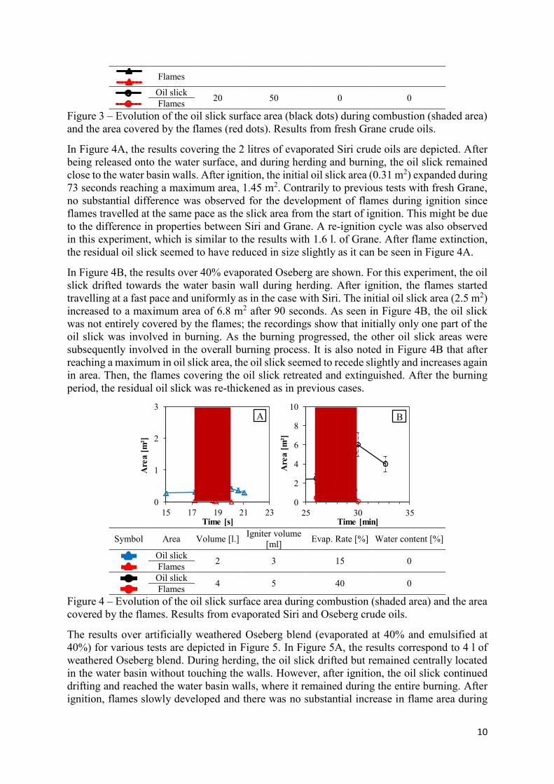
In Figure 4A, the results covering the 2 litres of evaporated Siri crude oils are depicted. After
being released onto the water surface, and during herding and burning, the oil slick remained
close to the water basin walls. After ignition, the initial oil slick area (0.31 m2) expanded during
73 seconds reaching a maximum area, 1.45 m2. Contrarily to previous tests with fresh Grane,
no substantial difference was observed for the development of flames during ignition since
flames travelled at the same pace as the slick area from the start of ignition. This might be due
to the difference in properties between Siri and Grane. A re-ignition cycle was also observed
in this experiment, which is similar to the results with 1.6 l. of Grane. After flame extinction,
the residual oil slick seemed to have reduced in size slightly as it can be seen in Figure 4A.
In Figure 4B, the results over 40% evaporated Oseberg are shown. For this experiment, the oil
slick drifted towards the water basin wall during herding. After ignition, the flames started
travelling at a fast pace and uniformly as in the case with Siri. The initial oil slick area (2.5 m2)
increased to a maximum area of 6.8 m2 after 90 seconds. As seen in Figure 4B, the oil slick
was not entirely covered by the flames; the recordings show that initially only one part of the
oil slick was involved in burning. As the burning progressed, the other oil slick areas were
subsequently involved in the overall burning process. It is also noted in Figure 4B that after
reaching a maximum in oil slick area, the oil slick seemed to recede slightly and increases again
in area. Then, the flames covering the oil slick retreated and extinguished. After the burning
period, the residual oil slick was re-thickened as in previous cases.
Symbol Area Volume [l.] Igniter volume
[ml] Evap. Rate [%] Water content [%]
Oil slick 2 3 15 0
Flames
Oil slick 4 5 40 0
Flames
Figure 4 – Evolution of the oil slick surface area during combustion (shaded area) and the area
covered by the flames. Results from evaporated Siri and Oseberg crude oils.
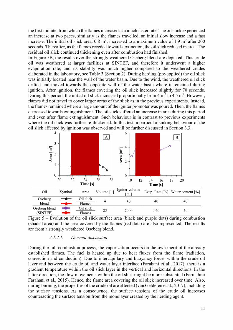
The results over artificially weathered Oseberg blend (evaporated at 40% and emulsified at
40%) for various tests are depicted in Figure 5. In Figure 5A, the results correspond to 4 l of
weathered Oseberg blend. During herding, the oil slick drifted but remained centrally located
in the water basin without touching the walls. However, after ignition, the oil slick continued
drifting and reached the water basin walls, where it remained during the entire burning. After
ignition, flames slowly developed and there was no substantial increase in flame area during
0.0
0.2
0.4
0.6
0.8
1.0
25 30 35Are
a [
m²]
Time [s]
A: Grane_0%_0% (1.6 L)
Grane_0%_0% (1.6 L)
Series1
0
4
8
12
16
30 35 40 45A
rea [
m²]
Time [s]
B: Grane_0%_0% (20 L.
trial 1)
Trial 1
Trial 1
0
1
2
3
15 17 19 21 23
Are
a [
m²]
Time [s]
A
0
2
4
6
8
10
25 30 35
Are
a [
m²]
Time [min]
B
Init
ial
vo
l. [
l]
Sy
mb
ol
Ev
ap.
rate
[%
]
Wat
er
conte
nt
[%]
Area
Oil SlickFlames
2 15 0
0
1
2
3
15 17 19 21 23Are
a [
m²]
Time [s]
A: Siri_15%_0% (2 L.)
Siri_15%_0%
Series1
0
4
8
12
16
30 35 40 45
Are
a [
m²]
Time [s]
B: Grane_0%_0% (20 L.
trial 1)
Trial 1
Trial 1
Oil
Sir
iO
seb
erg
Oil SlickFlames
10 40 0
0
1
2
3
15 17 19 21 23Are
a [
m²]
Time [s]
A: Siri_15%_0% (2 L.)
Siri_15%_0%
Series1
0
4
8
12
16
30 35 40 45
Are
a [
m²]
Time [s]
B: Grane_0%_0% (20 L.
trial 1)
Trial 1
Trial 1
11
the first minute, from which the flames increased at a much faster rate. The oil slick experienced
an increase at two paces, similarly as the flames travelled, an initial slow increase and a fast
increase. The initial oil slick area, 0.8 m2, increased to a maximum value of 1.9 m2 after 200
seconds. Thereafter, as the flames receded towards extinction, the oil slick reduced in area. The
residual oil slick continued thickening even after combustion had finished.
In Figure 5B, the results over the strongly weathered Oseberg blend are depicted. This crude
oil was weathered at larger facilities at SINTEF, and therefore it underwent a higher
evaporation rate, and its stability was much higher compared to the weathered crudes
elaborated in the laboratory, see Table 3 (Section 2). During herding (pre-applied) the oil slick
was initially located near the wall of the water basin. Due to the wind, the weathered oil slick
drifted and moved towards the opposite wall of the water basin where it remained during
ignition. After ignition, the flames covering the oil slick increased slightly for 70 seconds.
During this period, the initial oil slick increased proportionally from 4 m2 to 4.5 m2. However,
flames did not travel to cover larger areas of the slick as in the previous experiments. Instead,
the flames remained where a large amount of the igniter promoter was poured. Then, the flames
decreased towards extinguishment. The oil slick suffered an increase in area during this period
and even after flame extinguishment. Such behaviour is in contrast to previous experiments
where the oil slick was further re-thickened. In this test, a particular sinking behaviour of the
oil slick affected by ignition was observed and will be further discussed in Section 3.3.
Oil Symbol Area Volume [l.] Igniter volume
[ml] Evap. Rate [%] Water content [%]
Oseberg
blend
Oil slick 4 40 40 40
Flames
Oseberg blend
(SINTEF)
Oil slick 25 2000 >40 50
Flames
Figure 5 – Evolution of the oil slick surface area (black and purple dots) during combustion
(shaded area) and the area covered by the flames (red dots) are also represented. The results
are from a strongly weathered Oseberg blend.
3.1.2.1. Thermal discussion
During the full combustion process, the vaporization occurs on the own merit of the already
established flames. The fuel is heated up due to heat fluxes from the flame (radiation,
convection and conduction). Due to intercapillary and buoyancy forces within the crude oil
layer and between the crude oil and water layer interface (Farahani et al., 2017), there is a
gradient temperature within the oil slick layer in the vertical and horizontal directions. In the
latter direction, the flow movements within the oil slick might be more substantial (Farmahini
Farahani et al., 2015). Hence, the flame area covering the oil slick increased over time. Also,
during burning, the properties of the crude oil are affected (van Gelderen et al., 2017), including
the surface tensions. As a consequence, the surface tensions of the crude oil increases
counteracting the surface tension from the monolayer created by the herding agent.
0
2
4
6
10 12 14 16 18 20
Area [
m²]
Time [s]
B
0
1
2
3
4
30 32 34 36 38
Area [
m²]
Time [s]
A
0.0
0.2
0.4
0.6
0.8
1.0
25 30 35Are
a [
m²]
Time [s]
A: Grane_0%_0% (1.6 L)
Grane_0%_0% (1.6 L)
Series1
0
2
4
6
10 15 20
Are
a [
m²]
Time [s]
Oil Slick
Flames
12
When the oil slick area increases and the slick thickness decreases, there is an increase of the
heat losses through the water layer and the temperature of the crude oil is therefore reduced.
Hence, there is no enough vaporization rate from the heated crude oil to sustain combustion
(the flames recede) and extinction occurs. As the oil temperature decreases, the oil surface
tension also decreases to be below than the one from the monolayer created by the herding
agent. Such a postulate might partly explain the apparent ‘re-thickening” behaviour of the oil
slick observed when flames started to recede and after flames extinguished.
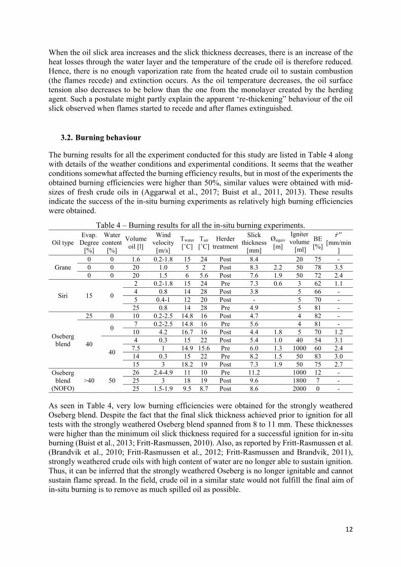
3.2. Burning behaviour
The burning results for all the experiment conducted for this study are listed in Table 4 along
with details of the weather conditions and experimental conditions. It seems that the weather
conditions somewhat affected the burning efficiency results, but in most of the experiments the
obtained burning efficiencies were higher than 50%, similar values were obtained with mid-
sizes of fresh crude oils in (Aggarwal et al., 2017; Buist et al., 2011, 2013). These results
indicate the success of the in-situ burning experiments as relatively high burning efficiencies
were obtained.
Table 4 – Burning results for all the in-situ burning experiments.
Oil type
Evap.
Degree
[%]
Water
content
[%]
Volume
oil [l]
Wind
velocity
[m/s]
Twater
[˚C]
Tair
[˚C]
Herder
treatment
Slick
thickness
[mm]
Øequiv
[m]
Igniter
volume
[ml]
BE
[%]
�̇�′′ [mm/min
]
Grane
0 0 1.6 0.2-1.8 15 24 Post 8.4 20 75 -
0 0 20 1.0 5 2 Post 8.3 2.2 50 78 3.5
0 0 20 1.5 6 5.6 Post 7.6 1.9 50 72 2.4
Siri 15 0
2 0.2-1.8 15 24 Pre 7.3 0.6 3 62 1.1
4 0.8 14 28 Post 3.8 5 66 -
5 0.4-1 12 20 Post - 5 70 -
25 0.8 14 28 Pre 4.9 5 81 -
Oseberg
blend
25 0 10 0.2-2.5 14.8 16 Post 4.7 4 82 -
40
0 7 0.2-2.5 14.8 16 Pre 5.6 4 81 -
10 4.2 16.7 16 Post 4.4 1.8 5 70 1.2
40
4 0.3 15 22 Post 5.4 1.0 40 54 3.1
7.5 1 14.9 15.6 Pre 6.0 1.3 1000 60 2.4
14 0.3 15 22 Pre 8.2 1.5 50 83 3.0
15 3 18.2 19 Post 7.3 1.9 50 75 2.7
Oseberg
blend
(NOFO)
>40 50
26 2.4-4.9 11 10 Pre 11.2 1000 12 -
25 3 18 19 Post 9.6 1800 7 -
25 1.5-1.9 9.5 8.7 Post 8.6 2000 0 -
As seen in Table 4, very low burning efficiencies were obtained for the strongly weathered
Oseberg blend. Despite the fact that the final slick thickness achieved prior to ignition for all
tests with the strongly weathered Oseberg blend spanned from 8 to 11 mm. These thicknesses
were higher than the minimum oil slick thickness required for a successful ignition for in-situ
burning (Buist et al., 2013; Fritt-Rasmussen, 2010). Also, as reported by Fritt-Rasmussen et al.
(Brandvik et al., 2010; Fritt-Rasmussen et al., 2012; Fritt-Rasmussen and Brandvik, 2011),
strongly weathered crude oils with high content of water are no longer able to sustain ignition.
Thus, it can be inferred that the strongly weathered Oseberg is no longer ignitable and cannot
sustain flame spread. In the field, crude oil in a similar state would not fulfill the final aim of
in-situ burning is to remove as much spilled oil as possible.
13
In relation with the regression rate results, the values obtained for some of the experiments
vary from 1.1 to 3.5 mm/min, these results correspond to oil slicks ranging from 0.6 to 2.2
metres in equivalent diameter, see Table 4. There is no clear correlation of the slick size on the
regression rate results for the experiments with fresh crude Grane and artificially weathered
Oseberg blend. The results show some variations when comparisons are made for similar tested
oil amounts with physical confinement (Fritt-Rasmussen, 2010; Garo et al., 2006; Koseki et
al., 1991). Such a discrepancy can be associated with the dynamic confinement process that
the oil slicks underwent during burning. These results are however in the same magnitude as
regression rates predicted by Buist et al. (Buist et al., 2013) for fresh crude oils and weathered
crude oils, although those predictions are for ISB diameters greater than 3.5 m. Similarly,
results from other experimental studies (Fritt-Rasmussen, 2010; Garo et al., 2006; Koseki et
al., 1991) show the same order of magnitude compared to the regression rates obtained in this
study.
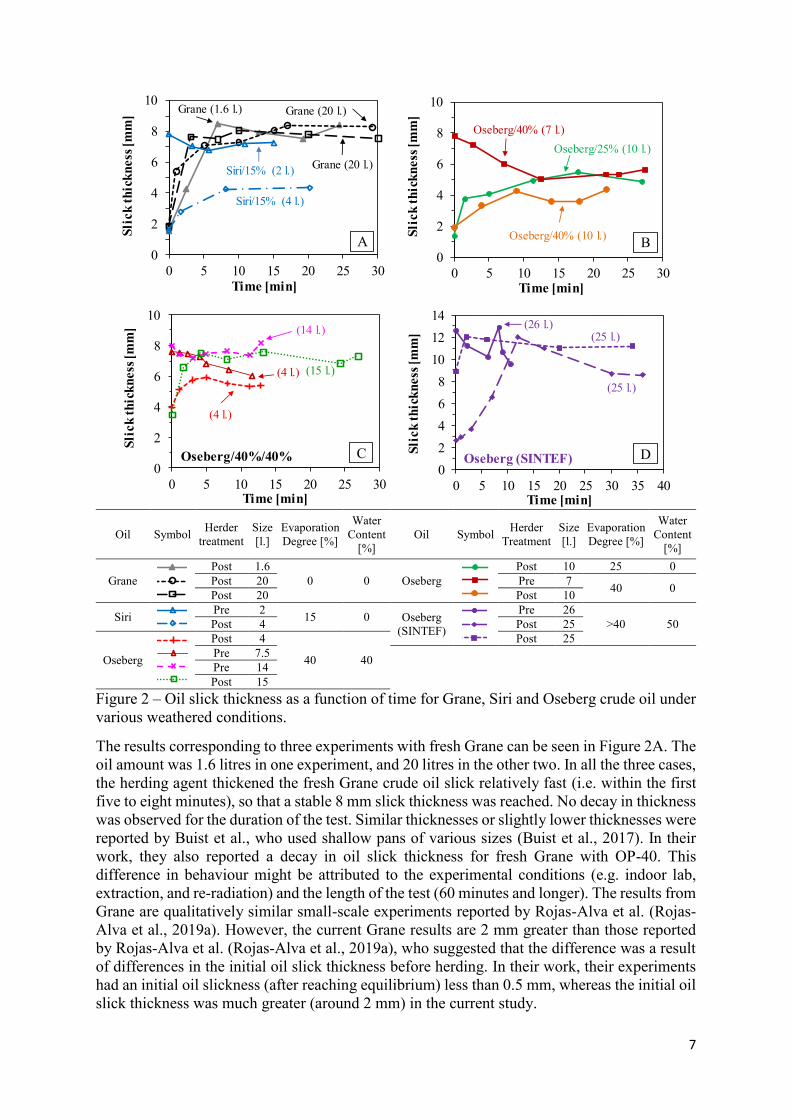
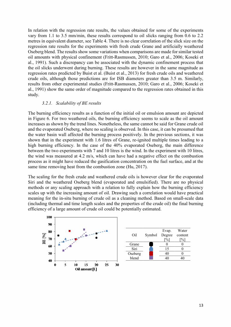
3.2.1. Scalability of BE results
The burning efficiency results as a function of the initial oil or emulsion amount are depicted
in Figure 6. For two weathered oils, the burning efficiency seems to scale as the oil amount
increases as shown by the trend lines. Nonetheless, the same cannot be said for Grane crude oil
and the evaporated Oseberg, where no scaling is observed. In this case, it can be presumed that
the water basin wall affected the burning process positively. In the previous sections, it was
shown that in the experiment with 1.6 litres of Grane, re-ignited multiple times leading to a
high burning efficiency. In the case of the 40% evaporated Oseberg, the main difference
between the two experiments with 7 and 10 litres is the wind. In the experiment with 10 litres,
the wind was measured at 4.2 m/s, which can have had a negative effect on the combustion
process as it might have reduced the gasification concentration on the fuel surface, and at the
same time removing heat from the combustion zone (Hu, 2017).
The scaling for the fresh crude and weathered crude oils is however clear for the evaporated
Siri and the weathered Oseberg blend (evaporated and emulsified). There are no physical
methods or any scaling approach with a relation to fully explain how the burning efficiency
scales up with the increasing amount of oil. Drawing such a correlation would have practical
meaning for the in-situ burning of crude oil as a cleaning method. Based on small-scale data
(including thermal and time length scales and the properties of the crude oil) the final burning
efficiency of a large amount of crude oil could be potentially estimated.
Oil Symbol
Evap.
Degree
[%]
Water
content
[%]
Grane
0 0
Siri 15 0
Oseberg
blend
40 0
40 40
40
50
60
70
80
90
100
051015202530
BE
[%
]
Oil amount [l.]
Grane_0%_0%Siri_15%_0%Oseberg_40%_0%Oseberg_40%_40%
14
Figure 6 – Burning efficiency as a function of the fuel amount for Siri, Grane and Oseberg
crude oils under various weathered conditions.
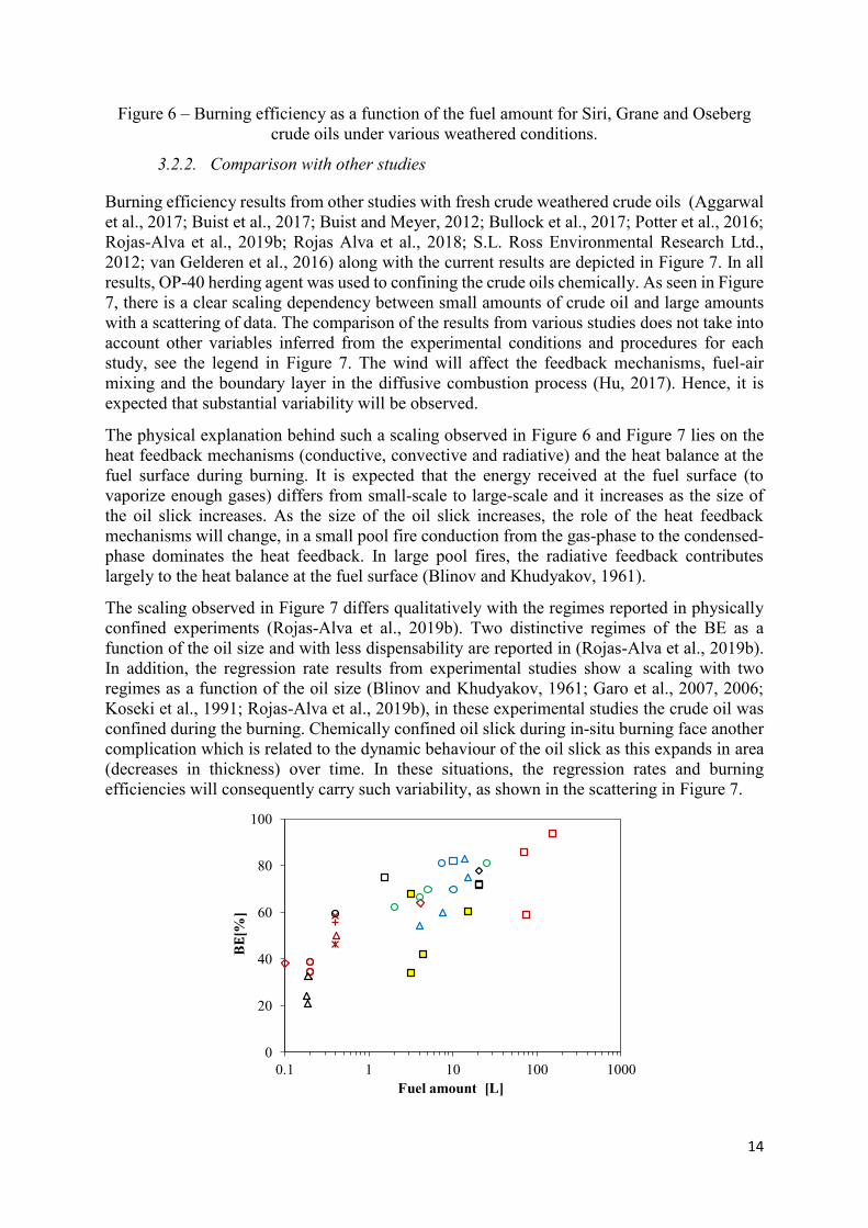
3.2.2. Comparison with other studies
Burning efficiency results from other studies with fresh crude weathered crude oils (Aggarwal
et al., 2017; Buist et al., 2017; Buist and Meyer, 2012; Bullock et al., 2017; Potter et al., 2016;
Rojas-Alva et al., 2019b; Rojas Alva et al., 2018; S.L. Ross Environmental Research Ltd.,
2012; van Gelderen et al., 2016) along with the current results are depicted in Figure 7. In all
results, OP-40 herding agent was used to confining the crude oils chemically. As seen in Figure
7, there is a clear scaling dependency between small amounts of crude oil and large amounts
with a scattering of data. The comparison of the results from various studies does not take into
account other variables inferred from the experimental conditions and procedures for each
study, see the legend in Figure 7. The wind will affect the feedback mechanisms, fuel-air
mixing and the boundary layer in the diffusive combustion process (Hu, 2017). Hence, it is
expected that substantial variability will be observed.
The physical explanation behind such a scaling observed in Figure 6 and Figure 7 lies on the
heat feedback mechanisms (conductive, convective and radiative) and the heat balance at the
fuel surface during burning. It is expected that the energy received at the fuel surface (to
vaporize enough gases) differs from small-scale to large-scale and it increases as the size of
the oil slick increases. As the size of the oil slick increases, the role of the heat feedback
mechanisms will change, in a small pool fire conduction from the gas-phase to the condensed-
phase dominates the heat feedback. In large pool fires, the radiative feedback contributes
largely to the heat balance at the fuel surface (Blinov and Khudyakov, 1961).
The scaling observed in Figure 7 differs qualitatively with the regimes reported in physically
confined experiments (Rojas-Alva et al., 2019b). Two distinctive regimes of the BE as a
function of the oil size and with less dispensability are reported in (Rojas-Alva et al., 2019b).
In addition, the regression rate results from experimental studies show a scaling with two
regimes as a function of the oil size (Blinov and Khudyakov, 1961; Garo et al., 2007, 2006;
Koseki et al., 1991; Rojas-Alva et al., 2019b), in these experimental studies the crude oil was
confined during the burning. Chemically confined oil slick during in-situ burning face another
complication which is related to the dynamic behaviour of the oil slick as this expands in area
(decreases in thickness) over time. In these situations, the regression rates and burning
efficiencies will consequently carry such variability, as shown in the scattering in Figure 7.
0
20
40
60
80
100
0.1 1 10 100 1000
Fuel amount [L]
ANS_OP40*ANS_OP40ANS_OP40ANS_OP40ANS_OP40_0%ANS_OP40_10%ANS_OP40_27%Grane_OP40*Grane_OP40Grane_OP40Grane_OP40DUC_OP40SIRI_OP40Oseberg_OP40Oseberg_OP40Oseberg_OP40
B
15
Oil
Sy
mbol
Evap.
Degree
[%]
Water
content
[%]
Wind [m/s]
Ice
coverage
[%]
Rig
Size
[m2]
Ref. Oil
Sy
mbol
Evap.
Degree
[%]
Water
content
[%]
Wind [m/s]
Ice
coverage
[%]
Rig
Size
[m2]
Ref.
AN
S
0 0 No 0 1 (Rojas-Alva et
al., 2019b)
Grane
0 0 No 0 1 (Rojas-
Alva et al.,
2019b)
0 0 0 0 12 (Buist and Meyer,
2012) 0 0 No 0 1
&12
(Buist et
al., 2017)
0 0 NS 10 1800 (Aggarwal et al.,
2017) 0 0 <1 0 20
(Rojas
Alva et al.,
2018)
0 0 <2 0 0.1&
9 (Bullock et al.,
2017) 0 0 <1.8 0 20 Current
0 0 0 0
12.1 (Buist et al.,
2017) Oseberg Blend
25 0 <2.5 0
20 Current 20 0 0 0 40 0 <4.2 0
27 0 0 0 40 40 <3 0
DUC 0 0 <6 <25 1 (van Gelderen et
al., 2016) Siri 15 0 <1.8 0 20 Current
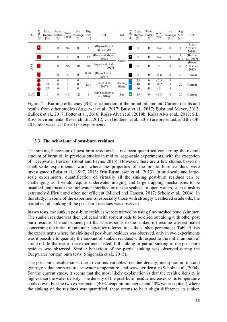
Figure 7 – Burning efficiency (BE) as a function of the initial oil amount. Current results and
results from other studies (Aggarwal et al., 2017; Buist et al., 2017; Buist and Meyer, 2012;
Bullock et al., 2017; Potter et al., 2016; Rojas-Alva et al., 2019b; Rojas Alva et al., 2018; S.L.
Ross Environmental Research Ltd., 2012; van Gelderen et al., 2016) are presented, and the OP-
40 herder was used for all the experiments.
3.3. The behaviour of post-burn residues
The sinking behaviour of post-burn residues has not been quantified concerning the overall
amount of burnt oil in previous studies in mid to large-scale experiments, with the exception
of Deepwater Horizon (Stout and Payne, 2016). However, there are a few studies based on
small-scale experimental work where the properties of the in-situ burn residues were
investigated (Buist et al., 1997, 2013; Fritt-Rasmussen et al., 2013). In mid-scale and large-
scale experiments, quantification of virtually all the sinking post-burn residues can be
challenging as it would require underwater imaging and large trapping mechanisms to be
installed underneath the fuel/water interface or on the seabed. In open waters, such a task is
extremely difficult and often not efficient (Michel and Hansen, 2017; Scholz et al., 2004). In
this study, in some of the experiments, especially those with strongly weathered crude oils, the
partial or full sinking of the post-burn residues was observed.
In two tests, the sunken post-burn residues were retrieved by using fine-meshed pond skimmer.
The sunken residue was then collected with sorbent pads to be dried out along with other post
burn residue. The subsequent part that corresponds to the sunken oil residue was estimated
concerning the initial oil amount; hereafter referred to as the sunken percentage. Table 5 lists
the experiments where the sinking of post-burn residues was observed, only in two experiments
was it possible to quantify the amount of sunken residues with respect to the initial amount of
crude oil. In the rest of the experiment listed, full sinking or partial sinking of the post-burn
residues was observed. Similar behaviour of the partial sinking was observed during the
Deepwater horizon burn tests (Shigenaka et al., 2015).
The post-burn residue sinks due to various variables: residue density, incorporation of sand
grains, residue temperature, seawater temperature, and seawater density (Scholz et al., 2004).
For the current study, it seems that the most likely explanation is that the residue density is
higher than the water density. The density of the post-burn residue increases as its temperature
cools down. For the two experiments (40% evaporation degree and 40% water content) where
the sinking of the residues was quantified, there seems to be a slight difference in sunken
0
20
40
60
80
100
0.1 10 1000
Fuel amount [L]
ANS_OP40*ANS_OP40ANS_OP40ANS_OP40ANS_OP40_0%ANS_OP40_10%ANS_OP40_27%Grane_OP40*Grane_OP40Grane_OP40Grane_OP40DUC_OP40Oseberg_OP40Oseberg_OP40Oseberg_OP40SIRI_OP40
B
0
20
40
60
80
100
0.1 10 1000
Fuel amount [L]
ANS_OP40*ANS_OP40ANS_OP40ANS_OP40ANS_OP40_0%ANS_OP40_10%ANS_OP40_27%Grane_OP40*Grane_OP40Grane_OP40Grane_OP40DUC_OP40Oseberg_OP40Oseberg_OP40Oseberg_OP40SIRI_OP40
B
0
20
40
60
80
100
0.1 10 1000
Fuel amount [L]
ANS_OP40*ANS_OP40ANS_OP40ANS_OP40ANS_OP40_0%ANS_OP40_10%ANS_OP40_27%Grane_OP40*Grane_OP40Grane_OP40Grane_OP40DUC_OP40Oseberg_OP40Oseberg_OP40Oseberg_OP40SIRI_OP40
B
0
20
40
60
80
100
0.1 10 1000
Fuel amount [L]
ANS_OP40*ANS_OP40ANS_OP40ANS_OP40ANS_OP40_0%ANS_OP40_10%ANS_OP40_27%Grane_OP40*Grane_OP40Grane_OP40Grane_OP40DUC_OP40Oseberg_OP40Oseberg_OP40Oseberg_OP40SIRI_OP40
B
0
20
40
60
80
100
0.1 10 1000
Fuel amount [L]
ANS_OP40*ANS_OP40ANS_OP40ANS_OP40ANS_OP40_0%ANS_OP40_10%ANS_OP40_27%Grane_OP40*Grane_OP40Grane_OP40Grane_OP40DUC_OP40Oseberg_OP40Oseberg_OP40Oseberg_OP40SIRI_OP40
B
0
20
40
60
80
100
0.1 10 1000
Fuel amount [L]
ANS_OP40*ANS_OP40ANS_OP40ANS_OP40ANS_OP40_0%ANS_OP40_10%ANS_OP40_27%Grane_OP40*Grane_OP40Grane_OP40Grane_OP40DUC_OP40Oseberg_OP40Oseberg_OP40Oseberg_OP40SIRI_OP40
B
0
20
40
60
80
100
0.1 10 1000
Fuel amount [L]
ANS_OP40*ANS_OP40ANS_OP40ANS_OP40ANS_OP40_0%ANS_OP40_10%ANS_OP40_27%Grane_OP40*Grane_OP40Grane_OP40Grane_OP40DUC_OP40Oseberg_OP40Oseberg_OP40Oseberg_OP40SIRI_OP40
B
0
20
40
60
80
100
0.1 10 1000
Fuel amount [L]
ANS_OP40*ANS_OP40ANS_OP40ANS_OP40ANS_OP40_0%ANS_OP40_10%ANS_OP40_27%Grane_OP40*Grane_OP40Grane_OP40Grane_OP40DUC_OP40Oseberg_OP40Oseberg_OP40Oseberg_OP40SIRI_OP40
B
0
20
40
60
80
100
0.1 10 1000
Fuel amount [L]
ANS_OP40*ANS_OP40ANS_OP40ANS_OP40ANS_OP40_0%ANS_OP40_10%ANS_OP40_27%Grane_OP40*Grane_OP40Grane_OP40Grane_OP40DUC_OP40Oseberg_OP40Oseberg_OP40Oseberg_OP40SIRI_OP40
B
0
20
40
60
80
100
0.1 10 1000
Fuel amount [L]
ANS_OP40*ANS_OP40ANS_OP40ANS_OP40ANS_OP40_0%ANS_OP40_10%ANS_OP40_27%Grane_OP40*Grane_OP40Grane_OP40Grane_OP40DUC_OP40SIRI_OP40Oseberg_OP40Oseberg_OP40Oseberg_OP40
B
0
20
40
60
80
100
0.1 10 1000
Fuel amount [L]
ANS_OP40*ANS_OP40ANS_OP40ANS_OP40ANS_OP40_0%ANS_OP40_10%ANS_OP40_27%Grane_OP40*Grane_OP40Grane_OP40Grane_OP40DUC_OP40SIRI_OP40Oseberg_OP40Oseberg_OP40Oseberg_OP40
B
0
20
40
60
80
100
0.1 10 1000
Fuel amount [L]
ANS_OP40*ANS_OP40ANS_OP40ANS_OP40ANS_OP40_0%ANS_OP40_10%ANS_OP40_27%Grane_OP40*Grane_OP40Grane_OP40Grane_OP40DUC_OP40SIRI_OP40Oseberg_OP40Oseberg_OP40Oseberg_OP40
B
16
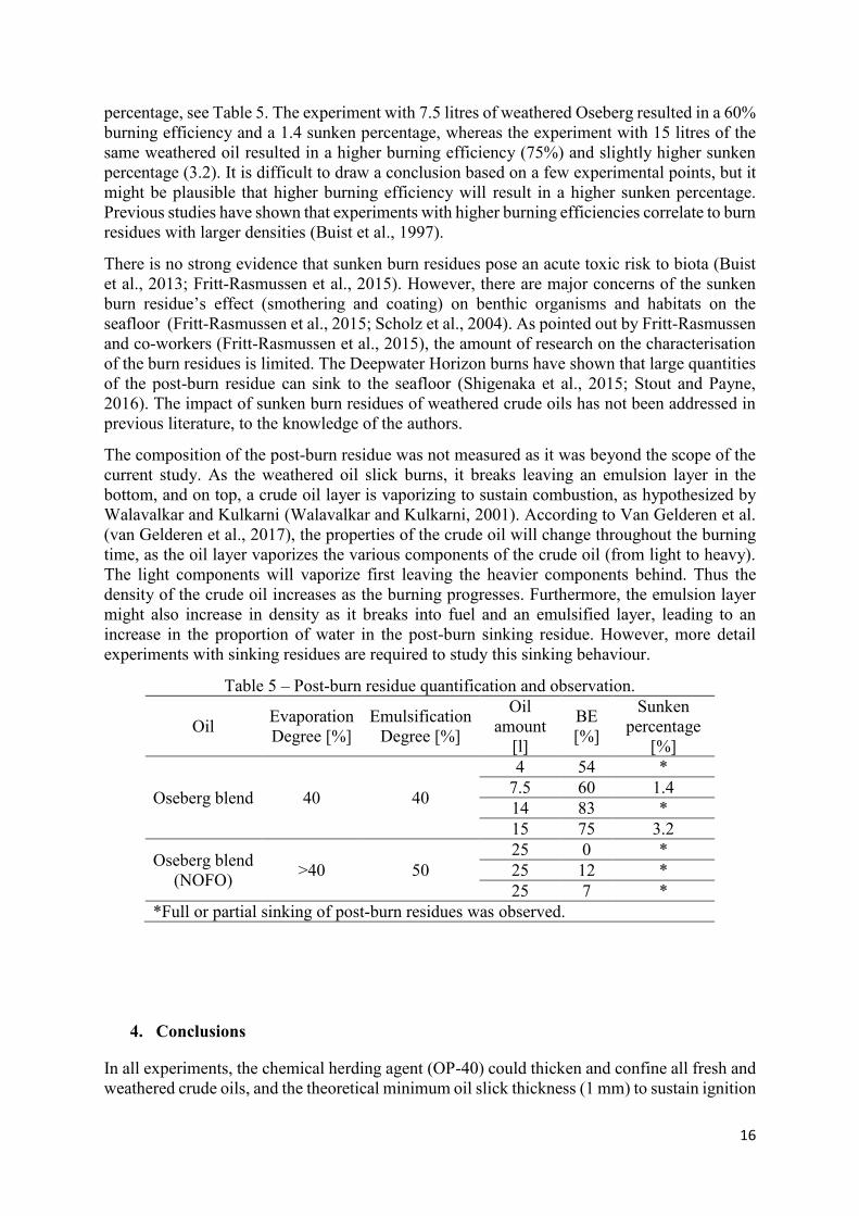
percentage, see Table 5. The experiment with 7.5 litres of weathered Oseberg resulted in a 60%
burning efficiency and a 1.4 sunken percentage, whereas the experiment with 15 litres of the
same weathered oil resulted in a higher burning efficiency (75%) and slightly higher sunken
percentage (3.2). It is difficult to draw a conclusion based on a few experimental points, but it
might be plausible that higher burning efficiency will result in a higher sunken percentage.
Previous studies have shown that experiments with higher burning efficiencies correlate to burn
residues with larger densities (Buist et al., 1997).
There is no strong evidence that sunken burn residues pose an acute toxic risk to biota (Buist
et al., 2013; Fritt-Rasmussen et al., 2015). However, there are major concerns of the sunken
burn residue’s effect (smothering and coating) on benthic organisms and habitats on the
seafloor (Fritt-Rasmussen et al., 2015; Scholz et al., 2004). As pointed out by Fritt-Rasmussen
and co-workers (Fritt-Rasmussen et al., 2015), the amount of research on the characterisation
of the burn residues is limited. The Deepwater Horizon burns have shown that large quantities
of the post-burn residue can sink to the seafloor (Shigenaka et al., 2015; Stout and Payne,
2016). The impact of sunken burn residues of weathered crude oils has not been addressed in
previous literature, to the knowledge of the authors.
The composition of the post-burn residue was not measured as it was beyond the scope of the
current study. As the weathered oil slick burns, it breaks leaving an emulsion layer in the
bottom, and on top, a crude oil layer is vaporizing to sustain combustion, as hypothesized by
Walavalkar and Kulkarni (Walavalkar and Kulkarni, 2001). According to Van Gelderen et al.
(van Gelderen et al., 2017), the properties of the crude oil will change throughout the burning
time, as the oil layer vaporizes the various components of the crude oil (from light to heavy).
The light components will vaporize first leaving the heavier components behind. Thus the
density of the crude oil increases as the burning progresses. Furthermore, the emulsion layer
might also increase in density as it breaks into fuel and an emulsified layer, leading to an
increase in the proportion of water in the post-burn sinking residue. However, more detail
experiments with sinking residues are required to study this sinking behaviour.
Table 5 – Post-burn residue quantification and observation.
Oil Evaporation
Degree [%]
Emulsification
Degree [%]
Oil
amount
[l]
BE
[%]
Sunken
percentage
[%]
Oseberg blend 40 40
4 54 *
7.5 60 1.4
14 83 *
15 75 3.2
Oseberg blend
(NOFO) >40 50
25 0 *
25 12 *
25 7 *
*Full or partial sinking of post-burn residues was observed.
4. Conclusions
In all experiments, the chemical herding agent (OP-40) could thicken and confine all fresh and
weathered crude oils, and the theoretical minimum oil slick thickness (1 mm) to sustain ignition

17
and flame spread was achieved. In some of the experiments, the water was pre-treated with
herder; hence, the herding effectiveness results should not directly be extrapolated to real cases;
these results are illustrative and used for comparison. The thickening behaviour of the herder
was found to depend on the oil type and weathering degree of the oil. During burning, the
ability of the surface monolayer created by the herding agent to thicken the oil diminished, but
after extinction occurred, the residual oil slick was re-thickened. It seems that the surface
monolayer is still active after being exposed to radiation from the flames. Further research is
required to elucidate the fate of the herder agent after in-situ burning experiments.
Ignition and subsequent flame spread were successfully achieved in all experiments; the
exception was the strongly weathered Oseberg with the highest water content. The burning
efficiency results together with results from other studies (same herding agent) showed that the
burning efficiency scaled with the oil slick size (in volume). However, the scaling is
qualitatively different from ISB results with physical confinement reported in the literature.
The sinking behaviour was observed to happen partially (residues remained below the water
level) or fully (residues sank to the bottom of the water tank) in the experiments with weathered
crude oils. The post-burn sinking residues were quantified concerning the initial oil amount in
two experiments. Further studies on the quantification of the burn residue as a function of the
weathered level of the crude requires further attention, as it might help in the full
characterization of sunken burn residues.
The results presented in the current study indicate that ISB of chemically weathered crude oils
may be feasible in real scenarios. However, more work is needed to fully characterise the
dynamic behaviour of the herded oil slick during burning. Also, the scaling dependencies and
sinking behaviour also need further attention. Scaling relations should be developed to predict
the burning efficiency of realistic scenarios based on small-scale testing. The current study will
hopefully encourage future investigations to continue working on these gaps.
Acknowledgment
The authors would like to thank NOFO for the financial support, DESMI for good discussions,
and SINTEF for providing the weathered crude oil. The authors are especially thankful to
Nordsjælland Brandskole for the support related to the mid-scale experiments.
18
References
Aggarwal, S., Schnabel, W., Buist, I., Garron, J., Bullock, R., Perkins, R., Potter, S., Cooper, D.,
2017. Aerial application of herding agents to advance in-situ burning for oil spill response in the
Arctic: A pilot study. Cold Reg. Sci. Technol. 135, 97–104.
Aksenov, Y., Popova, E.E., Yool, A., Nurser, A.J.G., Williams, T.D., Bertino, L., Bergh, J., 2017. On
the future navigability of Arctic sea routes: High-resolution projections of the Arctic Ocean and
sea ice. Mar. Policy 75, 300–317. https://doi.org/10.1016/J.MARPOL.2015.12.027
Bech, C., Sveum, P., Buist, I., 1992. In-situ burning of emulsions: the effect of varying water content
and degree of evaporation, in: Proceedings 15th AMOP Technical Seminar. pp. 547-559).
Blinov, V.I., Khudyakov, G.N., 1961. Diffusion burning of liquids. https://doi.org/AERDL-T-1490-A
Brandvik, P.J., Faksness, L.-G., 2009. Weathering processes in Arctic oil spills : Meso-scale
experiments with different ice conditions. Cold Reg. Sci. Technol. 55, 160–166.
https://doi.org/10.1016/j.coldregions.2008.06.006
Brandvik, P.J., Fritt-Rasmussen, J., Daniloff, R., Leirvik, F., 2010. Using a Small Scale Laboratory
Burning Cell to Measure Ignitability for In Situ Burning of Oil Spills as a Function of
Weathering, in: Thirty-Third AMOP Technical Seminar on Environmental Contamination and
Response. Environment Canada, Halifax, Nova Scotia, Canada, pp. 755–771.
Brogaard, N., Sørensen, M., Fritt-Rasmussen, J., Rangwala, A., Jomaas, G., 2014. A new
Experimental Rig for Oil Burning on Water–Results for Crude and Pure Oils. Fire Saf. Sci. 11,
1481–1495.
Buist, I., 2006. Mid-scale test tank research on using oil herding surfactants to thicken oil slicks in
pack ice: An update, in: Environment Canada Arctic and Marine Oil Spill Program Technical
Seminar (AMOP) Proceedings. Environment Canada, Vancouver, BC, Canada, pp. 691–709.
Buist, I., Canevari, G., Nedwed, T., 2009. New Herding Agents for Thickening Oil Slicks in Drift Ice
for In Situ Burning, in: Proceedings of the 33th AMOP Technical Seminar on Environmental
Contamination and Response. Environment Canada, Halifax, Nova Scotia, Canada.
Buist, I., Cooper, D., Trudel, K., Fritt-Rasmussen, J., Wegeberg, S., Gustavson, K., Lassen, P., Rojas
Alva, W.U., Zabilansky, L., 2017. Research investigations into herder fate, effects and windows-
of-opportunity, International Association of Oil & Gas Producers.
Buist, I., Glover, N., 1995. In situ burning of Alaska North Slope emulsions, in: Ray, J.P. (Ed.),
International Oil Spill Conference. Elsevier Ltd, Long Beach, California (US), pp. 139–146.
Buist, I., Meyer, P., 2012. Research on Using Oil Herding Agents for Rapid Response In Situ Burning
of Oil Slicks on Open Water, in: Proceedings of the 35th AMOP Technical Seminar on
Environmental Contamination and Response.
Buist, I., Potter, S., 2010. Barents Sea Field Test of Herder to Thicken Oil for In situ Burning in Drift
Ice, in: Proceedings of the Thirty-Third AMOP Technical Seminar on Environmental
Contamination and Response. Environment Canada, Ottawa, Ontario, pp. 725–742.
Buist, I., Potter, S., Belore, R., 2010. Employing Chemical Herders to Improve Marine Oil Spill
Response Operations, in: Thirty-Third AMOP Technical Seminar on Environmental
Contamination and Response. Halifax, Nova Scotia, Canada, pp. 1109–1134.
Buist, I., Potter, S., Nedwed, T., Mullin, J., 2011. Herding surfactants to contract and thicken oil spills
in pack ice for in situ burning. Cold Reg. Sci. Technol. 67, 3–23.
https://doi.org/10.1016/j.coldregions.2011.02.004
Buist, I., Potter, S., Nedwed, T., Mullin, J., 2008a. Herding Agents Thicken Oil Spills in Drift Ice to

19
Facilitate In Situ Burning: A new Trick for an Old Dog, in: International Oil Spill Conference.
American Petroleum Institute, pp. 673–679.
Buist, I., Potter, S., Nedwed, T., Mullin, J., 2007. Field research on using oil herding surfactants to
thicken oil slicks in pack ice for in situ burning, in: Arctic and Marine Oilspill Program (AMOP)
Technical Seminar. Environment Canada, Edmonton, Canada, p. 403.
Buist, I., Trudel, K., Morrison, J., Environmental, S.L.R., Aurand, D., Light, B., 1997. Laboratory
studies of the properties of In-situ burn residues, in: International Oil Spill Conference.
American Petroleum Institute, Edmonton, Canada, pp. 149–156.
Buist, I., Zabilansky, L., Guarino, A., Mullin, J., 2008b. Recent mid-scale research on using oil
herding surfactants to thicken oil slicks in pack ice for In Situ burning. Oil Spill Response A
Glob. Perspect.
Buist, I.A., Potter, S.G., Trudel, B.K., Shelnutt, S.R., Walker, A.H., Scholz, D.K., Brandvik, P.J.,
Fritt-Rasmussen, J., Allen, A.A., Smith, P., 2013. In Situ Burning in Ice-affected waters: State of
Knowledge report.
Buist, I.A., Twardus, E.M., 1985. Burning Unconfined Oil Slicks: Large Scale Tests and Modelling,
in: Proceedings of the 8th Annual Arctic Marine Oilspill Program Technical Seminar.
Environment Canada, Ottawa, Canada, pp. 103–130.
Bullock, R.J., Aggarwal, S., Perkins, R.A., Schnabel, W., 2017. Scale-up considerations for surface
collecting agent assisted in-situ burn crude oil spill response experiments in the Arctic:
Laboratory to field-scale investigations. J. Environ. Manage. 190, 266–273.
https://doi.org/10.1016/j.jenvman.2016.12.044
Bullock, R.J., Perkins, R.A., Aggarwal, S., 2019. In-situ burning with chemical herders for arctic oil
spill response: meta-analysis and review. Sci. Total Environ. 8, 55.
Dickins, D., Brandvik, P.J., Bradford, J., Faksness, L., Liberty, L., Daniloff, R., 2008. Svalbard 2006
Experimental Oil Spill Under Ice: Remote Sensing, Oil Weathering Under Arctic Conditions
and Assessment of Oil Removal By in-Situ Burning. Int. Oil Spill Conf. Proc. 2008, 681–688.
https://doi.org/10.7901/2169-3358-2008-1-681
Energetex Engineering, 1981. Burning of Crude Oil under Wind Herding Conditions. Energetex
Engineering, Waterloo, Ontario.
Evans, D.D., George, W., Baum, H.R., Walton, W.D., Kevin, B., 2001. In Situ Burning of Oil Spills.
J. Res. Natl. Inst. Stand. Technol. 106, 231–278.
ExxonMobil, 2018. Oseberg Blend [WWW Document]. Crude oils. URL
http://corporate.exxonmobil.com/en/company/worldwide-operations/crude-oils/oseberg-blend
(accessed 7.1.19).
Farahani, H., Alva, W.U.R., Rangwala, A.S., Jomaas, G., 2017. Convection-driven melting in an n-
octane pool fire bounded by an ice wall. Combust. Flame 179, 219–227.
https://doi.org/10.1016/j.combustflame.2017.02.006
Farmahini Farahani, H., Jomaas, G., Rangwala, A.S., 2015. Effects of convective motion in n-octane
pool fires in an ice cavity. Combust. Flame 162, 4643–4648.
https://doi.org/10.1016/j.combustflame.2015.09.021
Filler, D.M., Kennicutt, M.C., Snape, I., Sweet, S.T., Klein, A.G., 2015. Arctic and Antarctic Spills,
in: Fingas, M. (Ed.), Handbook of Oil Spill Science and Technology. John Wiley & Sons.
Fingas, M., 2011a. Physical Spill Countermeasures, in: Fingas, Mervin (Ed.), Oil Spill Science and
Technology. Elsevier Inc., pp. 303–337. https://doi.org/10.1016/B978-1-85617-943-0.10012-7
Fingas, M., 2011b. Weather Effects on Oil Spill Countermeasures, in: Fingas, Mervin (Ed.), Oil Spill
20
Science and Technology. Elsevier Inc., pp. 339–426. https://doi.org/10.1016/B978-1-85617-943-
0.10013-9
Fingas, M., Fieldhouse, B., 2015. Water-in-oil Emulsions: Formation and Prediction, in: Fingas,
Mervin (Ed.), Handbook of Oil Spill Science and Technology,. John Wiley & Sons, pp. 225–
270. https://doi.org/10.1002/9781118989982
Fingas, M.F., Halley, G., Ackerman, F., Nelson, R., Bissonnette, M., Laroche, N., Wang, Z., Lambert,
P., Li, K., Jokuty, P., Sergy, G., Tennyson, E.J., Mullin, J., Hannon, L., Halley, W., Latour, J.,
Galarneau, R., Ryan, B., Turpin, R., Campagna, P., Aurand, D. V., Hiltabrand, R.R., 1995. The
Newfoundland Offshore Burn Experiment—Nobe, in: International Oil Spill Conference
Proceedings. pp. 123–132. https://doi.org/10.7901/2169-3358-1995-1-123
Fritt-Rasmussen, J., 2010. In situ burning of Arctic marine oil spills - Ignitability of various oil types
weathered at different ice conditions. A combined laboratory and field study (PhD Dissertation).
Technical University of Denmark.
Fritt-Rasmussen, J., Ascanius, B.E., Brandvik, P.J., Villumsen, A., Stenby, E.H., 2013. Composition
of in situ burn residue as a function of weathering conditions. Mar. Pollut. Bull. 67, 75–81.
https://doi.org/10.1016/j.marpolbul.2012.11.034
Fritt-Rasmussen, J., Brandvik, P.J., 2011. Measuring ignitability for in situ burning of oil spills
weathered under Arctic conditions: From laboratory studies to large-scale field experiments.
Mar. Pollut. Bull. 62, 1780–1785. https://doi.org/10.1016/j.marpolbul.2011.05.020
Fritt-Rasmussen, J., Brandvik, P.J., Villumsen, A., Stenby, E.H., 2012. Comparing ignitability for in
situ burning of oil spills for an asphaltenic, a waxy and a light crude oil as a function of
weathering conditions under arctic conditions. Cold Reg. Sci. Technol. 72, 1–6.
https://doi.org/10.1016/j.coldregions.2011.12.001
Fritt-Rasmussen, J., Wegeberg, S., Gustavson, K., 2015. Review on Burn Residues from in Situ
Burning of Oil Spills in Relation to Arctic Waters. Water. Air. Soil Pollut. 226.
https://doi.org/10.1007/s11270-015-2593-1
Garo, J.-P., Koseki, H., Vantelon, J.-P., Fernandez-Pello, C., 2007. Combustion of liquid fuels
floating on water. Therm. Sci. 11, 119–140. https://doi.org/10.2298/TSCI0702119G
Garo, J.P., Vantelon, J.P., Koseki, H., 2006. Thin-Layer Boilover: Prediction of Its Onset and
Intensity. Combust. Sci. Technol. 178, 1217–1235. https://doi.org/10.1080/00102200500296846
Garo, J.P., Vantelon, J.P., Souil, J.M., Breillat, C., 2004. Burning of weathering and emulsified oil
spills 28, 753–761. https://doi.org/10.1016/j.expthermflusci.2003.12.013
Guénette, C.C., Sveum, P., Bech, C.M., Buist, I.A., 1995. Studies of in situ burning of emulsions in
norway, in: International Oil Spill Conference. American Petroleum Insitute, Long Beach,
California (US), pp. 115–122.
Hu, L., 2017. A review of physics and correlations of pool fire behaviour in wind and future
challenges. Fire Saf. J. 91, 41–55. https://doi.org/10.1016/j.firesaf.2017.05.008
Koseki, H., Kokkala, M., Mulholland, G., 1991. Experimental Study Of Boilover In Crude Oil Fires.
Fire Saf. Sci. 3, 865–874. https://doi.org/10.3801/IAFSS.FSS.3-865
Kunieda, H., Uddin, M.H., Furukawa, H., Harashima, A., 2001. Phase Behavior of a Mixture of
Poly(oxyethylene)−Poly(dimethylsiloxane) Copolymer and Nonionic Surfactant in Water.
Macromolecules 34, 9093–9099. https://doi.org/10.1021/ma011199i
Lane, P., Newsom, P., Buist, I., Nedwed, T., Tidwell, A., Flagg, K., 2012. Recent efforts to develop
and commercialize oil herders, in: 35th AMOP Technical Seminar on Environmental
Contamination and Response. Vancouver, BC, Canada, pp. 472–479.
21
Michel, J., Hansen, K.A., 2017. Sunken and Submerged Oil, in: Fingas, M. (Ed.), Oil Spill Science
and Technology. Elsevier Inc., pp. 731–758. https://doi.org/https://doi.org/10.1016/B978-0-12-
809413-6.00013-8
Nedwed, T., Tidwell, A., Buist, I., Belore, R., Canevari, G., 2012. Advances in treating agents for oil
spill reponse, in: SPE/APPEA International Conference on Health, Safety, and Environment in
Oil and Gas Exploration and Production. Society of Petroleum Engineers, Perth, Australia.
Nordvik, A.B., Champ, M.A., Bitting, K.R., 2003. Estimating Time Windows for Burning Oil at Sea:
Processes and Factors. Spill Sci. Technol. Bull. 8, 347–359. https://doi.org/10.1016/S1353-
2561(03)00097-5
Nuka, Research & Planning Group, L., 2010. Oil spill prevention and response in the U.S. Arctic
Ocean: Unexamined Risks, Unacceptable Consequences. Washington, DC.
Opstad, K., Guénette, C., 2000. Fire on the Sea Surface , Ignitability and Sustainability under Various
Environmental Conditions, in: Fire Safety Science - Proceeding of the Sixth International
Symposium. pp. 741–752.
Potter, S., Buist, I., 2008. In-Situ Burning for Oil Spills in Arctic Waters : State-of-the-Art and Future
Research Needs, in: Davison, W.F., Lee, K., Cogswell, A. (Eds.), Oil Spill Response: A Global
Perspective. Springer Dordrecht, pp. 23–39. https://doi.org/10.1007/978-1-4020-8565-9_5
Potter, S., Buist, I., Cooper, D., Schnabel, W., Garron, J., Perkins, R., Aggarwal, S., Bullock, R.,
Lane, P., 2016. Field Research on Helicopter Application of Chemical Herders to Advance In-
Situ Burning.
Rojas-Alva, U., Fritt-Rasmussen, J., Jomaas, G., 2019a. Experimental study of thickening
effectiveness of two herders for in-situ burning of crude oils on water (Under review). Cold Reg.
Sci. Technol.
Rojas-Alva, U., Fritt-Rasmussen, J., Jomaas, G., 2019b. Small-scale in-situ burning (ISB)
experiments with chemically confined crude oils on water (Submitted). Combust. Sci. Technol.
Rojas Alva, U., Skjønning Andersen, B., Jomaas, G., 2018. Pumice stones as potential in-situ burning
enhancer. Cold Reg. Sci. Technol. 146, 167–174.
https://doi.org/10.1016/j.coldregions.2017.12.004
S.L. Ross Environmental Research Ltd., 2012. Research on Using Oil Herding Agents for Rapid
Response In Situ Burning of Oil Slicks on Open Water - Final Report, S.L. Ross Environmental
Research Ltd. Ottawa.
S.L. Ross Environmental Research Ltd., 2007. Mid-scale test tank research on using oil herding
surfactants to thicken oil slicks in broken ice. Ottawa, Ontario.
Scholz, D., Warren, J., Walker, A.H., Micehl, J., 2004. In-Situ Burning: The fate of burned oil. API
Publishing Services, Washington, D.C.
Shi, X., Bellino, P.W., Simeoni, A., Rangwala, A.S., 2016. Experimental study of burning behavior of
large-scale crude oil fires in ice cavities. Fire Saf. J. 79, 91–99.
https://doi.org/10.1016/j.firesaf.2015.11.007
Shigenaka, G., Overton, E., Meyer, B., Gao, H., Miles, S., 2015. Physical and chemical characteristics
of In-situ burn residue and other environmental oil samples collected during the Deepwater
Horizon spill response, in: Interspil Conference.
Singsaas, I., Cooper, D., Buist, I., Potter, S., Lewis, A., Daling, P.S., Bråtveit, M., 2017. Field
experiment to validate herder and in-situ burning in open water, International Association of Oil
& Gas Producers.
Stout, S.A., Payne, J.R., 2016. Chemical composition of floating and sunken in-situ burn residues
22
from the Deepwater Horizon oil spill. Mar. Pollut. Bull. 108, 186–202.
https://doi.org/10.1016/j.marpolbul.2016.04.031
The Federal Interagency Solutions Group, O.B.C.S. and E.T., 2010. Oil Budget Calculator:
Deepwater Horizon, Technical Documentation: A Report to the National Incident Command.
National Incident Command, Washington, D.C.
Van Gelderen, L., Brogaard, N.L., Sørensen, M.X., Fritt-Rasmussen, J., Rangwala, A.S., Jomaas, G.,
2015. Importance of the slick thickness for effective in-situ burning of crude oil. Fire Saf. J. 78,
1–9. https://doi.org/10.1016/j.firesaf.2015.07.005
van Gelderen, L., Fritt-Rasmussen, J., Jomaas, G., 2016. Effectiveness of a chemical herder in
association with in-situ burning of oil spills in ice-infested water. Mar. Pollut. Bull.
https://doi.org/10.1016/j.marpolbul.2016.12.036
van Gelderen, L., Malmquist, L.M.V., Jomaas, G., 2017. Vaporization order and burning efficiency of
crude oils during in-situ burning on water. Fuel 191, 528–537.
https://doi.org/10.1016/j.fuel.2016.11.109
Walavalkar, A.Y., Kulkarni, A.K., 2001. Combustion of water-in-oil emulsion layers supported on
water. Combust. Flame 125, 1001–1011. https://doi.org/10.1016/S0010-2180(01)00220-6