Embed Size (px)
Citation preview

5/13/2018 Chemical Engineering Feb 2001 - slidepdf.com
http://slidepdf.com/reader/full/chemical-engineering-feb-2001 1/10
lips for SalaryNegotiation
Clean-in-placeTechniques
Chlor-alkali
Update
DesulfurizingDiesel Fu.els
Sizing Pipe
PneumaticConveying
NOx-controlTechnologies
Virtual
Training Tools
Customer-relationshipManagement
~ 1~
~I .~.., . .-,
'} . .'
A SpreadsheetSo!lution page 62
A Chemical WeekM8()Ciate8 Publieation
5/13/2018 Chemical Engineering Feb 2001 - slidepdf.com
http://slidepdf.com/reader/full/chemical-engineering-feb-2001 2/10
VOLUME 108, NO, a
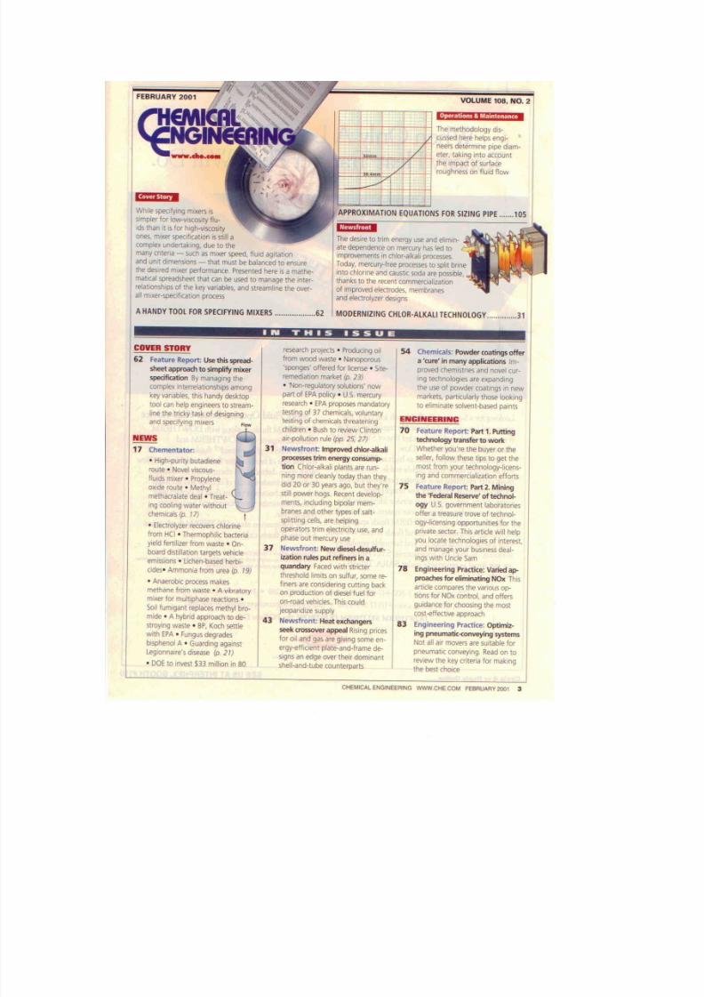
f:--+--+~:_;;'--!-lT he m et ho do lo gy d is -
c u ss e d h e re h e lp s e n qi -
n ee rs d ete rm in e p ip e d ia m-
e te r, t ak in g I nt o accountth e I mp a ct o f s u rf ac e
r ou g hn e ss o n i lu id flow
UM'D
White l pe d fy in g rmxe rs Iss im p le r f or l ow -v is co S it y f lu -
i ds t ha n It IS lor luqh-vecosrty0l16. mixe r spec i fi ca tion Is SlIII a
c om ple x u nd erta ln g, d ue to th e
m an y e m" r,a - s uc h a s rru xe r , pe ~d , flU Id a gita tio n
an d U nit d,m en <tons- th at m ust b e b a la nc e d t o e ll su re
the d e si re d m i xe r p e rf or m an c e. P re s en te d h e re IS a m a th e-
m ao ca l s pr ea ds he et t ha t c an b e , u se d to m an ag e t he I nt er -
r el at lO n ,f ll ps o f I he ke y v ar ia bl es , a nd s tr eam li ne t he 01/eI~
a ll m l~ r- sp ec lf ia ll io n p ro ce s s
A H A N D Y T O O L F O R S P . E C IF Y IN G M I XE R S . . . . . _. . . _ .. . . . . _. . 6 2
T he d es ir e t o t rim energy u se , m d e li mi n-
a te d ep en de nc e o n m e rc ur y h as led to
improvements Inch lo r . . . . ka ll p rocesses .
T od ay , m er cu ry -f re e p ro ce ss es to s pli t b ri ne I
i nt o c hl or in e a nd c a us n c s od a a re p o ss ib le ,
t ha n ks t o t he r ec e nt c omm e rd al iz a 1i on
o f i mp ro v ed e le ct ro de s , m em br an e s
a n d e l eC l ro l y. z er ~ g n s
M O D E R N IZ IN G C H lO R -A lK A L I T E C H N O L O G Y 3 1
IN THS ISSUE
COVER S TORY r es e ar ch p ro Je c ts . P ro d UC i ng a ll 54 C he mic als : P ow de r " ," !ln gs o ffe r
62 F e at ur e R e p< > rt : Use t h is s p re a d - fro m w oo d w as te ' N an op oro us a ' cu re ' i n m a ny a pp li ca ti on lS lm -
s he et a pp ro ac h to s im pli fy m ix er 'spooges' offered fo r lic en se ' S ne - p ro ve d c he mis tr ie s a nd n ov el c ur -
spedf icat ion By ma na gi ng t he ( em e di at lo n m a rk et (p . 23) I n g t e ch n o lo g ie s a r e. e ~ p an d in g
c om p le x I nt er re la ti on s hi ps am on g • ' No n- re g ul at or y s ol ut io n s' n o w th e use o f p ow der co atin gs m fl£'W
key v a( ja bl es . t ru s h a n~ y d e sk to p p art o f E PA policy. U . S . mercury m a rk et s, p a rt ic ul ar ly t he s e l oo k in g
t oo l c an h elp e ng in ee rs t o s tr ea m- r es ea rc h ' E PA p r o po s es m a nd at or y t o e li mi na te s ol ve n t- ba s ed p a in ts
line the t ri ck y t as k o f d e si gn in g t es ti ng o r 3 7 c h em ic a ls , v o lu n ta ryEERING
a n d s pe c if yi 'l 9 m ix e rs Flowt e st in g o f c n em ic a ls t h re a te n in g
c hil dr en · B u sh t o r ev ie w C lir rlo n 70 fe atu re R ep ort: P art 1 . P U ttin g
NEWS " o r- p ol lu t io n r u le {pp. 2 5, 2 71 li !c hn olo gy t ra ns fe r t o w or k
17 Chementator : 31 N ew sf ro nt : I mp ro ve d c hlo r- al ka li W he th ef yo u're th e buy er o r th e
" H ig h -p un ty b u ta d ie nep ro ce s se s t ri m e ne rg y c o ns u rn p- s elle r, fo llo w th es e tip s to g et th e
ti on C hlo r- al ka li p la nts a re r un - mo s t f rom yo u r t e ch r ol o gy - Ii te n s -ro ut e- N ov el v i5 Co U5 ~
n rn g m ore c le an ly to da y th an th ey m g a nd c om m er ci ali za ti on e ff or tsH u id s m IX e r' P r op yl en e
O X id e r ou te . M e th ylc ld 20 o r 3 0 y ears ago , but the y're 15 F e at ur e R e po rt : Part 2 , M i n in g
m e ti 1 ac ra la te d e al · T re a t-s ti ll p ow er h og s, R ec en t d ev el op - t he ' Fe d er al R e se rv e' o f t ec h no l-
1 1 1 9 c o ol in g w a te r w it ho u tm e nt s, i nc lu di ng b ip ola r m em o og y U .S . g o v er nmen t laboratores
ci1emicals (p. r 7)b ra ne s jl nd o th er IY P e5 o f s al t- o ff er a tr ea su r e t ro ve o f t ec hn ol -s pl it ti ng c e lt s, a re h e lp in g o gy -li ce ns ln g o pp or tu ni ne s f or t he
• E l e ct ro l yz e r r e co v e rs c h lo r in e o pe ra to rs tr im e le ct ric it y u se . a nd p ri va te s ec to r. T h is a rt ic le w o ll h e lpfr om H C I • T he rm op hi lic b ac te ri a p ha se o ut m erc ury u se y ou lo ca te t ec hn olo gie s o f i nl er 5t .y ie ld fe rtiliz er fro m w as te ' O n-
37 N ew sfr on t N ew d /e se l- de su lfu r- a nd m an ag e y ou r b us in es s d ea l-b oa rd d is ti ll at io n t ar ge ts v e hi cl e
i za ti on r ul es p ut re fi ne rs i n i! in gs w ith U nc le S amem iSS io n s • u cn e n- be s ed h e rb i -
q ua nd ary fa ce d w ith s tric te r 78 ~ n gi ne er in g P r ac ti ce : V a ri ed 'a p -c id es · A mm on ia fro m u re a (p , 19 )
t hr es ho ld l im it s o n s ul fu r. some re - p re ac he s fo r e lim in atin g N Ox T his• A na er ob ic p ro ce ss m ak es f il le rs a re c on si de ri ng c ut ti ng b ac k a rt ic le c om pa re s t he v ari ou s o p-m eth an e fro m w as te • A v ib ra to ry o n p ro du c1 io n o f d ie se l fu el fo r ti on s fo r N O . c on tr ol , a nd o ff er sm ix er f or rn ul np ha se re ac tio ns • o n-r oa d v eh id es . T hi s c ou ld g uid an ce fo r c ho os in g th e m os tS oil f um ig an t r ep la ce s m e th yl b ro - [ e op a ri d iz e s u p pl y c o s t. . ,H e c tr v e a p p ro a c hm lde • A hybrid a pp ro ac h to d e- 43 N ew .fro nt H ea t e xc ha ng ers 83 E ng in ee rin g P ra dic e: O ptim iz -SIfoylng wa st e • B P , K o c h s e ti le s ee k cr cs so v er a pp e al R is in g p ri ce s i ng p n eL Im a ti c- co nv e yi ng ' sy s te m sw ith E P A· F un gu s d eg ra de s fo r o il a nd g as lire g iv in g S Om e e n- N O l a ll a ir m o ve rs a re s uit ab le f orb is ph en o' A • G ua rd in g a ga in st e r gy ~ e ff io e n t p l at e -a n d -f rame de - p n e uma t ic c o n ve y in g . Read on toL e g io n n a"e 's d i se a s e (p . 211 S I g n s a n e dg e o ve r t he rr do rn tn a nt re vie w th e k ey a ite rla fo r m a1 <. in g• D OE to inv est $ 33 m illion In 80 sh e ll - a nd -t ube coumerna r t s th e best choice
CHEMICALENGINEERING WWW.CIiECOM FEBRUARY 2001 3

5/13/2018 Chemical Engineering Feb 2001 - slidepdf.com
http://slidepdf.com/reader/full/chemical-engineering-feb-2001 3/10
Cover Story
M i x l e r S e , c i f i c a l i : o nilia Sp ~ e a d s h e e l ·f r y t h is s p r e a d s h u t's l o g ic t o s im p l i f y
a n d s ;p e e d U P I m i l e r s p e c i f i c a . t i o n
Steven F. Drnry
S h ar pe M ix er s. I nc .
tewis E . GalesReyNo, Inc.
l ui il s m i lc in g has la ng b ee n c on si d-
Iered an art that ~q~:h:esthe diU-cafe ba la ndng o r 1lliIrer speed, Iluidagitation., batch dimensions, and
otlllV v l! I' ia o le s. M o r eo v er , t he s p ec if i-ca tio n o r fluid mixers for 19w-visccs i ty
app lications, wm.le simpler thM f(lr
,n ui ds o f hlgb v is cc sl ty . i s q ui te COID-
pler, dne t< > the many cri tcri !l that CllJl
be =00 to define mixer perfbnnance ..
Presented. here is .. mathsmsbical
spreadsheet Ihat can be used b o
str ea mlin e m ix er s pee i:fi ca tiD ll. T JUs
spreadsheet. cilO be ilownlb.dea di -
rectly fromwww .sbarpembnracom.
Designed for low-viscosity·fluid ap-
plications, the program illustrates the
interrelationships of mixer-perfor-
mance criteria, including bow-these cri-
teri~. va(y with sc aleu p. O nc e zu ix er
Specif iea.t iOll is understeed for low-vis-
cos i t :y l lWds , t he r ea de r W iU h e a ble to
handle the tnore-wmpficated situations
Ih.at inevitably occur wben high-eiseos-
ity fluids o r . su li ds a re e nc a uu te re d.
Average,bulk.tluid velocityi t . . wgnificant percentage of fluid-mix-
ing applications in the ebemleal
p ro ce ea in du tr ia s (C P O d ea l w it h le w-viscasit y f luids. where mild, medium
or violent miring: 81'S the only materia
specified. Since these mixing .regimes
haee no standard ilefinition, illiorpre.
t anol l is usual ly left: !o the user; Here,
the authol1l a:i :bit rini ly define mild.
m ed iU J n a nd mlent mixing ' !IS th e"qui.va len. t of average bulk-f la ld ve-
locities ( V O l of 19, 3 6 and 54 ftlmin,
TABlE5IJMMARY
'TABLE t. Mild ! 1 'I l >< , in g ;
TABLE 2. M~dmi.i"9
T:ABLE 3. Med i.m m ixi ng;
T.A.BLE 4. ~;um m;"i"9:TABLIE 5,. Vialenl mi.ing:
TABL'E 6. Violenl mixing:
Bvlk-~u i .d - e l O : c i l y
Bv l k- nu id " " Io c ll r
B u l k- " ui d v el oc it y
au l~-Aui" ""Iooi]y
Bolk-Auid ".,Joeil)'
Bvlk-Auid "ebdly
I B f t/ m in , D/,18 ft/m in. ];)/T
.3 6 ft lm in . I i) IT
3 6 f t/ mi n, o/r5 4 f t/ mi n, D iT54 h/m /n . O jT
0.25
0.35
6.15
0.35
0.250.35
INOMENCLAl iURE·
respectively. The bulk-fluid vel<lcity
in the mixed tank is defined in Eq)1n .lion: (l) as the pri:tqary pumping ca-
pac ity of the mrpel le r in ftSlmin (Q),
divided by the tank'. horizontal
crcss-aectienal area. in ft2 fA). All
terms are defined in the. ncmencla-
ture box, above.
v,=g mA
Quantified values for mild,
medium and violent mixing have
been cited.in the literature and arenecessary in this exercise as 8 start-
i ng point for other calcula tions . How-
ever, f u . i . s artiCle demonstrates toot,regardless ofthe characteris tic chosen
as the basis :For mixer spec:l :l icat iOll
and scal eup, other design parameters
will vary in 'W a ys tha t are n ot n eees-
6 :1 C HE MIC Al. E NGlN5 'E RIN G W W W .C HE .C OM FE BR UA RY 2D D1

5/13/2018 Chemical Engineering Feb 2001 - slidepdf.com
http://slidepdf.com/reader/full/chemical-engineering-feb-2001 4/10
sar ily imuit ive to the engineer. No one
characteristic can be singled out for
selection and scaleup in all cases .
Defining m.Ud .ng inten i~yWhen cansulting WW l an equipment
desiCJler, the end user should describe
the mixing requirements in his OTher
own wards. It i during this recitalthat the designer forms judgments
about the intensi ty of mixing reqru,.e,j
to SlltislY process need . In addttt on,
because an accurat e and complet e def·
inition o r mixing requirements is
vital , the designer and use, should
jointly fill out a mixing-data sheet
that methodically def ines a ll t he im-
portant aspects ofmixer performance.
This step in the design and pecifi-
cati.on proce mWil not be rushed or
oversimplified. Once a mixer is manu-
factured and installed, itis difficult for
changes to be made to the uni t without
re_roav ing ita n d r et um in g it to t he l ac -
Wry• .fu some instances, components
..,thin th e mix.eT may limi t cerl :Jti n
change . For in stance, a larger motor
may exceed tbe capabilit y ofthe drive
(also known" th e gear redueerl or the
mixer shaft , which drives the impel ler.
If that is the ca e. then a completely
new mixer would be requi red. To fur-
ther complicate matters, 0 new mixer
migh t bes ig n i .5 c an tl y heavier, thereby
exceeding L h . e cIIpaci.ty of the process
vessel or the building structure.
Shalt
Balf!e
Z Impeller
c
t-----T----i
FIGURE·1. The basic mixer dimensions,
shown (B, C, 0, T,Bnd Z) a re def ined In
lila nomencl<!lIJre box ( 1 ' . 62). Thespreadsheets (Tables 1-{j) emplov or rratles. '010.25 .nd 0.3510 demonstra te the
Imp.~. on mixer operal in s pa rameters of
varying this ·rallo
Complicating factor
Viscosi~:Tables 1-6 (pp. 63-68) were
generated using' a Microaofl. Excel
preadsheet uuderthe pretense thatmost f luid applications involve low-vis-
cosity liquids. '!'bis assumptio» is neces-
sary in order fur the data generated by
the t ab l to be accurate, If i1 ui d vi .
i 1 ;y is greater than 100 cP, then the se-
lection charts sbould be used with great
eantio or not at all, Ai l viscositiea in-
crease, thelikelibood thatIluids will ex-
hibit non-Newtonian behavior also in-
creases. The design or mixers fur
bigh-viscosity applications or for non-
N ew to ru a n f lu id s r eq u ir es c o ns id er ab leexpertise an d should be avoided by
those with limited experience:·
Solids': Tile presence of solids .in. 0
process fluid : complicates mixer de-
sign, and ruay hamper the ur efulnes
of !.be selection tables. Fluids with
rapidly sett ling aHde may requiremere that are m O D Y t imes la rger
than those suggest ed by the tables.
01) the othor band, aile may use the
tables to design mixers that contain
sol ids with. s low set il il lg Tate.
G",ses: lujected or formed in situ,
gases tlutt are present i . 1 I a liquidmedium pose a major problem in
mixer specification. If gases are pre-
sent in .nrore than miniscule concen-
tr a tions, the selection tables shou ld
Dot be used.
Equipment description
The basie mixer eonfiguratton recom-
mended for simple applications is
shown in Figure 1 (above, le ft) . As il-
lustrated in t his sketch, the bat ch has
a Iiquid-depth-to-tank-diameter rat io
CHfMICAl ENGINEffiING WWW.CHECOM FEBRUARV 200 I 6.3

5/13/2018 Chemical Engineering Feb 2001 - slidepdf.com
http://slidepdf.com/reader/full/chemical-engineering-feb-2001 5/10
(defined as ZITI of approximately 1.[1.
A batch. of this shape 'is easy to mix
using a single hydrofoil impel le r, . 1 0 -
e aW i a pp l' O' <i Jn at el y 1 13 0 1 t h e l iquid
depth (Z) from the bo t tOm Qftbe tank.
This distance is d ef in ed ~ C!Z~ll4.
8hooo batches, Dr those With ZI'rTa~tios signifi=Uy less than 1 .0, ar emum diff icult 10mix because th e nor-
mal f lnw patt erns produead by tit " im-
peller c a nn o t f o rm in th e batch apace .On the othe. rlmnd. bat ches withZ,rrapos sig:n:lfi=tly fI' t ' Iate, than 1.0
may requtre multiple impellers,
Ratios of impelle r diameter to tank
diameter (D/Tl n orm ally ra ng e fro m0.25 to 0.4, with OJ¥.!being idea l. Fig·
me 1 depicts one of four ant iswirl lmf·
fl.es posi t ioned at a 90·deg angles re -speeti.n' to the taJlk cil'll1lmt<).nm.~.
These baffles preveat low·vi.sj1Q~[Lylu-
ids f rom swirling du e In t he i 'm p e l1 e r
ro tefum. Tbe ratio of bafile width l'O
tank diameter, or BIT, should beE'l'JaI to 1112. Baffles designed tn thisratio are ",,,,,epted as ""' industry s t a n -derd fo r low.";scos.ity·fll,lid applica-
t io n s .1 wg e1 ' b a il le ' d t) n o tn e c es s ar il yi,m p ro v e .Q!iXer performance ""c ; l may,
in fact, interfennoith it.
Criticll11designpueametersHorsepower and shail: .spaed are tb.
t",o mosL-criticalparameters involved
in de. fi ni:Qg the mixer' s capabili ty to
d ~l i" er a certain l ev el o f l l e; r li J rmaace ,such as a specified buls-fluid velocity.
U n fo rtu na te ly , t he y a re m o re d if li cu ltto specify than a mixer', gen,,~al di-
mensions. Motor borsepower an.d
mtser shaf t s p ee d d e £i o e the <lgit .abion
inten"sity impmed by the mixer andalso cO .n JmuWl l aW t he m L "" r's s i" ,. La
a manufacturer,
T<>furtber explain the spoci:f icat i l1I1.
o f m ix er size, c on sid e r tw o different
lO·hp misers with respect ive shaft
speeda or 1,750 rpm and S4 rpm. Th.
first mixer runs at the actual motor
speed and does not nflj!{) a gear re- ,
ducer . Howe",>.c,: in o rd er f o. t th e s ec -
o nd .m :i:x er to o pera te a t IIl ow er s ha ft
speed, it will require a gear reducer ,
whiob. is II! ,'ery heavy, "astly piece of
machinery. Thas, the Br . t mixer
might ",.,fgh 600 lb and cost $5 ,000,
while the second mixer n:t ight weigh
1 ,5 00 l b a nd c os t $ lO ',O O 0- -2 Q,O O O .
Th e eomplete des.igu of a wi'el' from
a mechanical standpcini m an Impor-
tant but compl i c a t ed task, Most fluid
mixers use a c!lll~il' ' ' 'j}' ' ' ' iI. ,holt ( a shaft ,with DO bottom bearing) to drive aDD
support Lb. impelLer. ''rhe sh.aft IIIU~t
be o f s u il ic ie n t d iam et er 1Q keep i . 1 1 e
st resses p:roduoed by terque, es well as
the bending momenta, witlrln accept·
able limits. Bending moments occur
when the impelle r exper iences f lnctn-
ating horizontal forees that piISl i it to -
wards the vessel! ! wails. 'lil,ese forres
.xtend evsr the lenglih of the lll i, ", r
shaft tp the lowost bilaring ill. the gear
reducer , thereby producing II bending
,;wment that adds to the tcrque-In-
duced Shall. stresses.
Furthermore, the designer mhet de-
termine the natural frequencies of vi-
bratitm of tile drive, $haft and im-
peUe'r system Iall measured in rpm}.
an d ensure that they dliJ IJ1 ' from the
' O pe ra ti ng s pe ed . o f t he s y st em . If th efrequencies coincide, the resultant vi,
b ra tir m w ill 'lu i. k1 }1 fat igue tho mixer -
shaft to r other major componeuts ), re -
ducing its 1if00ycle to min utes.
O ne w ay to a v o id ' th is seeoario is toselect t a n k s with aZI Taraboot 1.0. At
this m tio . the canliilevered·shaft lel lgtb
and reqWJ:ed tank diameter are opti·
mized, A design ratio of ztr » 1 usu-
ally danntas lONg, slender vessels unix-
ers ""til long, cansilevered shaftslwhiilh are e:"I;>eDsl~·e. ecmplicated me -
chan i ca l C!lIlfigll",tioos.
Dlscusslen of ealeulatdonsTables 1--6 were generated uaing the
equat ions and calculations t llat foUow.
Six "ebi; of conditions, ~hOWJl in 111.
tahl~ summary(ilQx,
p, (2) were choselJto delllOrulLr.W hf)'w jhe bulk mIld ve-
loci ty (V') and DIT rat io impact mixer
5.pecifioatimru;. When these va lues a reiIlput at the top (If th e spreadsheet , as
shown. in the table insert (p. 62, top
right) tb. prog ram c",hihte. ih, in fer-
mation Iis ted in ColumnsB thr.ough It.for each ofthe batch volumes input into
Co IUDU I A. W rt. bio p ra ctic al limits.these tables can be gnnerllted for n
wid . . range or parameters, by &peci( '~c.
ing finer graduations ofDIT and Y'.
Cokrrm. .A . batch "oJ",,,",e (V): A
r an ge o fu sr u" -s :~ 'f .i ed " ,. ..I nl ll @; ,i ll U . S .
gal, i :input 'into Cells Al3 through
A S 3 . T h es e v ol um e s, w hil e arbitrary,
a ret yp ic al o Fm oa t miring applicat ions .
For the examples ' provided, B . range of
25()....:lO.OijO ge l has heen.seleeted. AB aprecauti.onazy measure, the spread -
shee t logic should not be ,,!led for ""I·
UlD"S great ar than 10,000 gal
Columns Band C, diooU!ter ( '1:)
and liquid depth (Z),A s previously
s tat ed, aba tch shape with UT=l.1'1 it;
i dea l for mix:ing and. agita ti<m. With
this asswnptiOf,l, the t !U)k diameteriT). cal culat ed 'i n inches using til.
vo lume. in C o lu m n A . , E ql Ja ti <l .. ( 2) c an
be s o lv e< ! f o r R 1;0 yield the radius o f aeylinderin .It. '!'be liquid depth (Zl if!
equal to twioe the diameter (2ft), as
repm;;ented below:
Vgo1 =( i l E ~ ) '(2R) (7.4.l!~~ ) [2}
The spreadshee t automatiepJly con-
ver ts the radius to diameter, by multi-
plying by 2, and inches to feet, by mul-
tiplying by 12. T he re&u:lts are
generaeed in Column B and copied
into Column C, where they 9.1$0repre-
eDt ]jquid depth.
C(l lumn D, ' impeller diameter r D J :T he :im p elle r d ia m et er C D ) is c alc ula te d
ininches , by m ul tip ly in g th o diameter
oCthemi> : . , d batch t T l f r om ' C o lu J D I lB ,
by th e ratio of impellar diameter to tank
diameter (D' I.TJ, whic.b i$ lnputinto Cell
E6, W J : re n designing the spreadsheet
equations, oneIll"!I.' tJopi>E6 as $E$6to
. f i x the value, iIItbat eell for relative cal-e ula tio ns d on e ill sn bs eq ue nt ro ws.
Columll.F, ea1"uiateci.halhpeed (N):
T h e s p ro a .d S h e et Ill","" d e C c r r o . m e the.haIts p ee d b e fo re itcan ca l eul a te shalt pow" , "
rsBp]:in C olo ;J W lj!;.B utt o c a]c u]a teN , ~
required pumpingrate, Q, must first befuund in fi ll pe r minute, T o do this, the
sl'~ U5IlS bulk-fluid velocity (lI'}
from Cell 1 2 I input .as C e l l $ 1 $ 2 ], c a lc u la te s
tim b a tc h bm iw n J: al crcss-scetinnal !Im!l
1 A l li nm the tank diam' l t i l r (T) listed in
ColumnB ria Equatioll (3) ,
(3)
and then sol...es Equaeion (1) for Q .
Once Q ismolVn, the basis for the cal-
eulafions in. c ol um n . F becomes the di -mensionless pumping number IVII a s
$ bawn in Equation (4):

5/13/2018 Chemical Engineering Feb 2001 - slidepdf.com
http://slidepdf.com/reader/full/chemical-engineering-feb-2001 6/10
O HE MIC Alo NG IN EE RIN G W VO "< 'I. CH E. CO M F EB R UA RY 2 00 1 65

5/13/2018 Chemical Engineering Feb 2001 - slidepdf.com
http://slidepdf.com/reader/full/chemical-engineering-feb-2001 7/10
Cover Story
The. -preadsheel then ealeulates the
shaft speed t N J , in rpm, required 'to
produce the pumping rate (Q), given
th e impeller diameter mH i:o m C o lu m nD, and the dimensionles pumping
number uVqi from Cell $E$8.
Column E, calcula.ted .haft power
(SHp): The shaf t horsepower i shown
in Column E. The basis for the calcu-
lation ofSHp i tho power number, a
sbown inEqu~tion (5) below.
This equation must be. rearranged to!!OI". for P. In this equat ion, P is ac-
tua l ly a form o f H I' whose' UIUI.$
have been "fixed" to render N dimen-
sionless . When th e :SllreaiL,beet cal-culates S Hp. it incorporates this cor-
rection factor. A ll other terms are
knO\\1I1: Np j dsfined inCell $E$7,
liquid density (p) is calculated u ing'
the specific gravity from Cell sess,impeller diameter (D) is known from
Column D, and aha:! '! .speed, N, has
just been generated in Oelunm Fusing Equal:ion (41.
Columll G. minimum. horsepower
of the motor (Hpj: The minimum
molor horsepower is cal¢ul<>ted by di-
viding the haft power in Column E
hy O . 5 . T Ili i the value used to
specify mixer performance because itaccounts for' vari ati ons in f luid prop-
erties, as well a for power losses
through gears , bearings and seal .
tendard motors do no~ come in the
ratings calculated in thiS column.
The user hould purchase the next-
larger standard motor, to minimize
the purehase cost over that of" non-
standard motor.
For example, motors come in stan-
dard sizes, uch as 1, 1.5, 2, and 3 hp.
[fYOI l order II motor with a L23·hp
rat ing, which i not available off the
.helf, you would b. char g ed a high
price ror eustomieation of the non-
standard motor, for the sake of mini-
mizing operating costs. Rather, a
manufacturer may rightly encourage
you to purcha e a. Lb-hp motor,
which would probably be in stock.
(4)
Column J, potoer per volume
(H_pIV): To build this column, divide
the minimum motor horsepower
from Column G by the mixed volume
from Column A divided by 1,000.
This gives units of hp per thousands
of gall')ns, and Is used mora fre-
queatly than, say, torque per vol·
ume, wben analyzing mixer perfor-
manee, 'otic" that the required
horsepower per volume decrease
with volume for mixers that del iver B
constant bulk-fluid velocity.
Column H, torque (T qi : Torque is •
significant characteris tic or property
used to specify a mixer, and is calcu-lat ed using Equation [6).
53,025·Hp
TQ=--N-.--
' In this equnt iou, l : / p is ~he 11I1m-
mUD) horsepower obta ined from Col-
um n G, an d N is obtained from Col-
umn F. As hewn in Column R, ilie
lprque required for mixers providing a
constant bulk-fluid velocity increase
with volume.
(5)
Cotumn 1, torque per noiume
IT l tV ) ; Torque: per volume can. be
used to scale up a mixer, provided
OM wants to maintain a similar bulk-
fluid velocity in the lat'gAr tank a in
the smaller 00e. The valuesjn Col-
umn I are generated b y dividing
torque (Column Hl by the batch vel-"me (VI. The latter, expressed in
units of rhcusanda of galion'S, is cal-
culated by dividing the value in Co l -wnn.A b y 1,000 gal when writing the
equaticn in Cell 113. Notice that theT Q I V reQuJred fo r mixers delivering
" const ant bulk-f luid velQcity ;8 tha
same for any volume listed in atabl e.
Cul.wIl. J{, R'ey"old$ number
(NR.): The Reynolds number is cal cu-
lated in Equation (7) using tbe im-
pel ler diameter from Co lumn D, shall
peed from Column F, the density as
specific gravi1.), from Cell $E$5, and
fluid viscosi ty from Cell 5E$<l ..A con-
stant 10.;is required on the right
hand side of the equa tion to make the
units dimensionless.
N " . :D"Np!'
1> 6 CH EM ICA l E NGJN~R lNG W WW .CHE .COM Fa lA UA AY 2001
(6l
Column ll~ lurn.ouers per minu ..-e ;
Batch turnovers per minute is a com-
mon cbaracteriatle considered by mixer
designers . Turnover iscalculated by di-
The Reynold number i~ a ratio. of
inertial to viscous forces. lL is well
known that as the Reynolds Dumberincreases, t he f lo w regime i s becon r i n .gmore turbulent. Ln order {or the equa-
tions in the spreadsheet to be valid,
the mixed Ilow must be turbulent (in
other words, NR. must be above
10, (100). Column K serves to "er i fythat t urbulent conditi ons exist, and to
illu stra te the e ff ec t o r s ca le 00 N!W.
inee the user of !:bese selection
charts is usual ly more concern ed with
th e overall magnitude of NR<' rather
than Its exact valne, Co111.= K is ex-
pressed iu sc ientifi c nota tion. Notice
lha.t N!W increases w ith v olu me for a
fixed bulk-fluid velocity.
Colu-mnr. Froude number (N~:The Fronde number, calculated via
EqUll tion (8), expresses the rat io of' in-
arbial to grm,;t.lltiotull Inrces impartedby an impel.ler to the process fluid.
(8)
In order (or NI'r to be dimensionless,
Nmust be converted to revls by divid-
mg b y 6 0 B lo lin , D m ust be conver ted to
f!. bydividing by 12 injJt and ilia accel -
eration of gravity mllst be input as 32
IlIs2. The higher the Froude number,
the greate r the surface deformat ion of
the mixed fluid. Nl'r decreases with in-
creasing volume. Therefore, the user
cane.~ calmer surface condi tions as
the volume iaereasea, while the bulk-
fluid veloci ty remains r ,on.smnt .
Baflle!linhibiHheformation ofa sur-
f a c e v o r tex ( in oilie r words, a V· haped
surface .with tbe bottom tip of the V at
th mixer shall) because they prevent
the fluid from rotat ing horizontally and
centr ifugnlly towards the outer edge of
th e tank. B u t b aJ lle s d o n o t p re ve nt t he
surface of the fluid from surging, or
f rom oilie r types o r motion. Bl!(lause
this art icle eonsiders only ful ly baIDed
a pp llc at io ns ( wh er e a s ur fa ce v or te x is
not produced), the Froude number is
not signif icant. i n the correlat ions dis-
cussed. However, it Js helpful La see
bow it varia with volume.
(7)

5/13/2018 Chemical Engineering Feb 2001 - slidepdf.com
http://slidepdf.com/reader/full/chemical-engineering-feb-2001 8/10
C;H~MIC;ALENGINEERING WWW.Ct!~.COM FEBRUARY2001 67

5/13/2018 Chemical Engineering Feb 2001 - slidepdf.com
http://slidepdf.com/reader/full/chemical-engineering-feb-2001 9/10
viding tho pumping capacity of the im-
pel ler lQ) in galIroin by the botch vol-
ume in gaUOIlS from Column. A. 'Ihe re -sult is lImin or turnovers per minute ,
In this instance, Q is calculated using
EqyBt ion (4). The pumping number
f rom Ccl lES7, t he s ha ft s pe ed in rpmtfro m C olu mn FI , a nd . impeller diame-
ter (from Column DI are multipl ied. D
is first divided by12 to convert-to It, and
then raised to th e third pow er. T he en -
tire resul t is multiplied by 7.4S to <an-
vert from f t 3 /mi n to galI~
A l th o ug h t h es e v a lu es o fQ a rs s ho w ni n Column 0, the mathemabioal equa-
tion is fneorpcrated directly into Col-
umn M , wbich bo" that the number of
tumevers per minute decreases with
vo lume, for a f ix ed bulk·fluid veloci ty .
ColURm ,impeller tip speed (U,):
The impel ler t ip speed is calculated by
E qu at io n 1 91 :
U, =rJ)12
Impelle r diameter and shaft. peed
are obta ined from Columns D and F,
'Cl!pectively, U, is f ixed under condi-
t i ons of increasing batch vul ume and
constant bulk-fluid velocity.
Column 0,pIlmping capacity (Q):
T!)e impel ler pumping capac ity (gal-
l o n s per m in u te ). w hic h i s u se d t o c a l-
(9)
Column Q , Prandtl nwnber (Np);
The Prandtl number is a function of
fluid properties such all v iscosi ty ,heat eepacity, and thermal conduct iv-
ity. as defined in Cell. $E$4, $L 5
and $LS6, respectively. The values
have b e en c e rr ee te d to render NPr di -mensienle s , I is calculated inCol-
umn Q to facil itate subsequent calcu-
culata turnovers per minute in. Col-um n 1 1 1 , is listed in C o 1w :n n 0 t o i llu s-trate its variation with volume at a
f ixed bulk-fluid valoeity.
Coll.lm"P, blend.time (9): Blend t ime
lin minutes) can be calculated using
Equation 1101, where No is the blend
numberfmm CeUSE$9andNis thecal-
eulated shaft speed from COlumn F:
N.=N9
HGWe\'eT,Equation [lllisthe basis for
caloula t ing blend time as shown in Col -
um n "P . T his rn ore -c or np le x fo rm o f the
b l en d n umb er i n cl u de s t he e f fe c t o fD I 'l '.
o~ N._
!··(~tThis correlation predicts that the
blend time for a batch increases with
volume for 8 fixed bulk-fluid velooity
- constant velocit ies take longer tot raverse the la rger tanks.
6.8 Cf-{EMICALfi.NG1N~RING WWW.CIiE.CQM fEBRUARY 2Q01
nOI
h T = K . [ D " N e ) a ( G p I J ) ~ ( J 1 _ ) ' (13)
k p /, p",
In Column R, 'ii.calculated using
tank diameter (T) Irom Column.8,
t he rm a l c o n du c ti vi ty (k) fro m C ellSL86, th e heat-transfer-equat ion eon-
stanf ( k " J from Cell $L$7, NRr from
Column K, N Pr tl-om C01= Q , the
ral:io o r fluid v is co $ it ie s f rt lm c el lsE$4 and Cell $L$4, and lhe expo.
Den t s 11, b and c from Cells ,$I. 8, $L 9
and S1$10, respectively. 'I'hls correla-
tion predicts that the agitated-film
la tions of the bea t transfer coef fici ent
lid in Co l umn R.
(11)
Column R, agitated-film heat-
transfer coefficient (h): The ngi-
tat ed-fi lm beat- transfe r coeff ic ient is
required to estimate the ability to add
or remove heat from a IlI'OC~SS ve el,with the given heat-exchange S\lJ"·
fa ces . B elo w is th e standard cor re l a-tion from which the heat-transfer co-
efficient i~ calculated:
NN. ~ N ; . N ~ , ( J : ! . . ) ' (12)P~II
Th i s dimensionless ccrre lar iee can
be expanded a shewu in Equation
(13). where the agitated film heal-
transfer coefficient emerges as k on
the lett hand side:

5/13/2018 Chemical Engineering Feb 2001 - slidepdf.com
http://slidepdf.com/reader/full/chemical-engineering-feb-2001 10/10
Cover Story
TABI.E 7. Motor t lo"epowar SpeelffcaHonac hieve a \ r 0
mixer, If on
V0
Mol,,, H pN Tumovers V' A
h horsepower togal In, hp rpm per min it/min m'in 1!tuJ(h)(ft2j('f)standard CO
IMOO 35 .S 2.52 117 1 . · 5 11 1.2 SIling til" speed
10,000 SO . 1 0.66 42 1.5 18 1. 6 401'torque will1,946.9 in.-lb
TABLE 8. Scalaup Using a 3 -h pV MoforH N
InT~bV' a mos t eertainl
gal hp rpm tl/m;n min I ),O O O. ca 1 B P P
Table 4 InformaHon 1 . 0 00 1.13 183 J89.4 36 0.4 duces a torqu
fxlsllng appnCOf iOA 1.000 1 190 332 i sc los enoug
Tabl .. 4lntormoHon 5,000 3.31 107 1.946.9 36 0.6 ommended by
Possible recommenc:loHon 5,000 5 100 3 ,150 .3 E
Recommended 5.000 3 10 0 1,a90.S'Olber Readinp
heat- transfer coeJI ic ient decreases dri ve. The user should se Jec l a ge ar re-t. D k k i !, Y . D a v id
' C u d agitAtion
with increasing volume. for a constant. dueer tha t y ie lds the nex t- lower ava il - F"m"w:)' 197
bulk-Iluid velocity. In practice, 8 de- able shaft speed. 2. Ssr;e!l";, RJ. . .~uLh
signer must provide additional surface lflhe motor is larger than specified P ce:Gb.3.JI
area o r larger ternperature-driving by th.e table, and the gear reducer ae- 3. Bc r J inslc i , D n,rithm.~l:la-.r':l)
[0""_ to get the required heat transfer leeled gives a shaft speed lower than,. B rodltey. I
in larger vessels, the one in Table 7, the mixer manu- '"I"nI.n.porl
facturer should adjust ilie impeller pro:u:b." Mc C
Compnrfsen among tables diamete r so tha t it tha t ful ly u ti li . .e s3S!l-$9.
6. ,Il!iliy. D.,'ldA general observatien of Ibe selection the higber horsepower and lower iogpn>l.olo>nO
cllartsreveals several dynamiQll oc- shatt peed. 6. Di c :u , . .Davideurring a lll ong the table s. Table s 1 1I..tpc. ro r
and 2 . which ref le ct 11 constant bulk- ealeupi impIifiedMJm:h 1994.
fluid veloc ity of 1 ll NOlin , have DIT Another use for the se se lec tion table s~. FManD, Julia.
va:ncei ;l £mpell
r at ios of 0 .25 and 0 .35, r espect ively. i s to fac il itate mixer sca leup . Assume, i:atiom, Ch.r.m.
When D IT inc reases , be value s c fHp, for instance, that an operator bas II S.Napta.S ..
N,TQ.Tif"', BplV. R " NEr , u, an d 1.000-gal.li'luid·pbase mixing appliea- tiOti," H . 8 .
W"lIey.New'ih dec rease. The same observa tions tiau in whieh the mixer i s pe rfo rming
9. Olrlah ue, J .Y.hold t rue when comparing Table 3 sa t israc tor iJy . This: mixer has a l-hp McGraw-Hill
with Ta ble 4 (whe re V' = 36 ftJminJ motor and a ahaft peed of' 190 rpm.
and Table 5 with T a ble 6 rwhere V = The ope rata r wants to spe cify a mixe rAuthors
54fiJminJ. that will perform just a well in 8
5,OOO·galapplication. ,
Predicttng proce re ults The first step involves examination of
lee
he tables presented prove to b~ in- the six. selection tables tolind opemting
valuable during' seiactlon o r mbiars. rendition- that d~y 'res~mble those of
Suppose a mixer is re quire d for a Jiq- the LOOCl-ga l~ng applica ticn , th. ..- eby
~J iid-phase proce ss in a lO,OOO'gal b e d di n g l ig h t on the mixing jn~
tank, and thai the term "mild blend- predueed by this mixer-motor duo. A s-ing" i 8 uitab le descr ip tion of the urns- that one ident ifies the ccndi ticns. in ,\mil]1rm;Ylw
mi ring inte nsity required, Using the th.llrst row aCTable 4, lo r medium mix-of CatUnr:nw Ul
A1QbE, and is •
two tables for mild mixing a t 10,000 ing and a DIT !If 0 .35. a s shown sspa- inth». '~~Q.fW
gal, one extracts the following data, ra~y inTableS (abovel.
~
recapitulated in Table 7 (a bove). The The tmljue delivered by the existing
most-important data are the motor l,QOO..galmi= is s l ight ly less than thathorsepower ( Hp l and he mixer ~h1'l:1t s.peciliedbyTaWe 4 fur prod ue ing a bulk-
speed. ince one: e annob rea dily pur- fluid velocity QF36 flImin. It is safe to as-
chase a 2.52- or O.66-hp motor off the 5umetlwt a 5.QOO..galmixerwbose torque
shelf, th. next-latger available motor is sIigjilly less than that speci fied by
- in this case a 3·bp or a 314-hp, Ta ble 4 will perform similarly to the ex-bolhBS.""" ~
should be selected. isting llliNerin the l"OOO-galapp l iea t ien , mte U.a. iy . Os
Furlherlllore. it m a y ! lo t b e p o sa ib le Notice th.at Table 4 recommends a ~["{ [QdSIm:rp<.1 \II'lt.Gale:Si:iatn
to purchase a ll?-rpm or 42·rpm 3.31·hp motor ope ra ting aL107 rpm to P">~
f 36 f t lmin in 8 5.OOCl-gal.
e vinere se the motor
5 hp (the next -h ighe r,ufigurabion), while .redue-
to 100 rpm, the resul ting
be much higher than the
specified in Table 4.
m oto r a t 100 rpm will al·
) ' be adequ ate fo r the
licahlon because it pro-
e of 1 ,890 .8 in- lb , which
h to th e 1,946.9 in.-Ib rec-
the table. •
ditedbyRil.a.L.D'.4quirro
S.• aruI Ricks. Rl.bard w" L U t ·
refresbee eedee. C lu !m . EDI ! • •
6.
C:d~i:~~,~~~~r id . " T .h e Ad.""nL t~ rthe Algo-
urt. N ew Y o rk . . ' 20 0 0.
toOOrt "and H~"l)(ty, H.o..rryC_Phenomena, A Unified Ap-ruw-Hill. New York~ 19~ pp.
"Facing tb.e~h91Ien~ ormix.·uidi. eliml. E'lg .•~ltsy201)0.
S. and Heinr~an.il RamI!!Sh.Duid arWc,g, elrl 'm.. 1i"8"
n ' 8. R 'D d B(IIkker, Andre. Ader geomet;ry l~lIIliquid agi..
E :n g: .A Ug 'll aL 1 99 11
~c: . PriDcip~eB"and Appllcabled Press, Ko dac sb e, T ok yv an d
ork, L975.
I "j-r111id 1 ' 1 ' 1 0 0 0 8 T"' lthnolom-:N l! .W 'Y o r: k . 1 9 S3 .
CHEMICAL ENGlN.,ERING WWW.CHE.COM FEBRUARY 200; 69


![arXiv:math/0102043v1 [math.LO] 6 Feb 2001](https://img.dokumen.tips/doc/110x75/6168830fd394e9041f701776/arxivmath0102043v1-mathlo-6-feb-2001.jpg)


![arXiv:cond-mat/0102220v2 [cond-mat.soft] 13 Feb 2001](https://img.dokumen.tips/doc/110x75/620ded5c0c9a4b241d547d17/arxivcond-mat0102220v2-cond-matsoft-13-feb-2001.jpg)