Embed Size (px)
Citation preview

1
Call 01952 680213
Chemical Dosing Pots
Engineered Products & Solutions Ltd
Visit www.epands.com
Introduction
Dosing pots are required in order to feed liquid chemicals such as
corrosion inhibitors into closed Heating & Cooling systems.
Dosing pots consist of a mild steel vessel with inlet (return) and outlet
(flow) valves, a drain valve and a filling valve. They are also equipped
with a steel tundish, air release valve, wall mounting brackets and a
non-return valve.
Specification• Mild steel shell to BS 1387 (up to 150mm, schedule 20 used on
200mm and above)
• Welded to BS EN 287
• All dosing pots that are designed to PD 5500:2000 category 3 (C E
marked) have the following Max. Working pressures:
• 3.5 litres to 6 litres inclusive-14 bar
• 10 litres to 20 litres inclusive-10 bar
• 25 litres to 35 litres-8 bar
• Dosing pots that are not designed to the above specification
are also available with a maximum working pressure of 14 bar
throughout the range (3.5 litre to 35 litre).
• Powder coated paint finish.
Installation
It is important that the dosing pots are fitted correctly in to the
system to allow trouble-free chemical feed. This is best achieved
by connecting across the main flow and return pipe work. Ideally
the flow connection should be made on to the bottom of the
dosing pot (valve C), and the return the top (valve B).
The dosing pot is designed for the conditions stated on the name
plate. Please ensure that the system into which the dosing pot is
being installed has adequate protection to ensure that the product
is operated within these limits at all times.
Operation
1. Isolate pot: close all valves
2. Drain pot: open valves A and D
3. Charge pot: close valve D and introduce solution via valve A (tundish)
4. Expel air: open air vent until solution appears
5. Inject treatment: close valve A fully and open valves B and C.
6. Protection or warnings should be applied to ensure that personnel do not come into contact with the pot so as to avoid burns.
7. A check valve is installed to help prevent accidental scolding and chemical saturation (blow back) of personnel operating the pot.
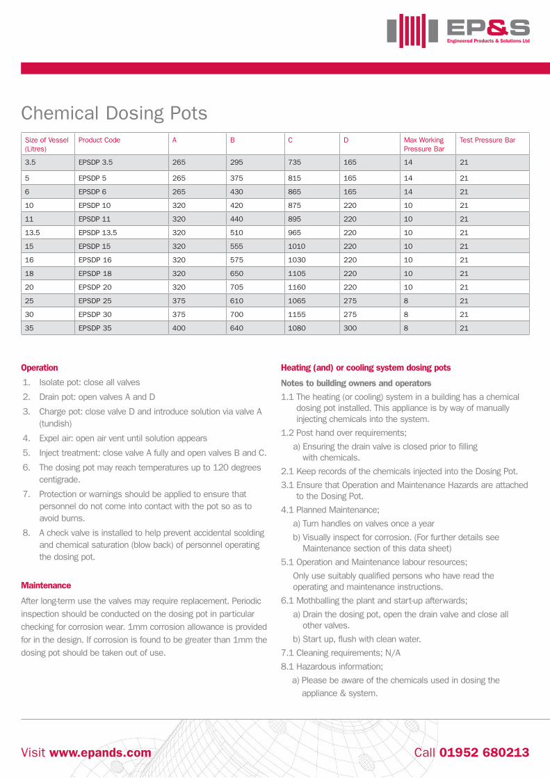
Size of Vessel (Litres)
Product Code A B C D Max Working Pressure Bar
Test Pressure Bar
3.5 EPSDP 3.5 265 295 735 165 14 21
5 EPSDP 5 265 375 815 165 14 21
6 EPSDP 6 265 430 865 165 14 21
10 EPSDP 10 320 420 875 220 10 21
11 EPSDP 11 320 440 895 220 10 21
13.5 EPSDP 13.5 320 510 965 220 10 21
15 EPSDP 15 320 555 1010 220 10 21
16 EPSDP 16 320 575 1030 220 10 21
18 EPSDP 18 320 650 1105 220 10 21
20 EPSDP 20 320 705 1160 220 10 21
25 EPSDP 25 375 610 1065 275 8 21
30 EPSDP 30 375 700 1155 275 8 21
35 EPSDP 35 400 640 1080 300 8 21
Engineered Products & Solutions Ltd
Call 01952 680213Visit www.epands.com
Chemical Dosing Pots
Operation
1. Isolate pot: close all valves
2. Drain pot: open valves A and D
3. Charge pot: close valve D and introduce solution via valve A (tundish)
4. Expel air: open air vent until solution appears
5. Inject treatment: close valve A fully and open valves B and C.
6. The dosing pot may reach temperatures up to 120 degrees centigrade.
7. Protection or warnings should be applied to ensure that personnel do not come into contact with the pot so as to avoid burns.
8. A check valve is installed to help prevent accidental scolding and chemical saturation (blow back) of personnel operating the dosing pot.
Maintenance
After long-term use the valves may require replacement. Periodic
inspection should be conducted on the dosing pot in particular
checking for corrosion wear. 1mm corrosion allowance is provided
for in the design. If corrosion is found to be greater than 1mm the
dosing pot should be taken out of use.
Heating (and) or cooling system dosing pots
Notes to building owners and operators
1.1 The heating (or cooling) system in a building has a chemical dosing pot installed. This appliance is by way of manually injecting chemicals into the system.
1.2 Post hand over requirements;
a) Ensuring the drain valve is closed prior to filling with chemicals.
2.1 Keep records of the chemicals injected into the Dosing Pot.
3.1 Ensure that Operation and Maintenance Hazards are attached to the Dosing Pot.
4.1 Planned Maintenance;
a) Turn handles on valves once a year
b) Visually inspect for corrosion. (For further details see Maintenance section of this data sheet)
5.1 Operation and Maintenance labour resources;
Only use suitably qualified persons who have read the operating and maintenance instructions.
6.1 Mothballing the plant and start-up afterwards;
a) Drain the dosing pot, open the drain valve and close all other valves.
b) Start up, flush with clean water.
7.1 Cleaning requirements; N/A
8.1 Hazardous information;
a) Please be aware of the chemicals used in dosing the
appliance & system.

3
Engineered Products & Solutions Ltd
Call 01952 680213Visit www.epands.com
Connecting the dosing pot to the system