Embed Size (px)
Citation preview

MANHOLE COVERS & ENGINEERING CASTINGSDESIGN • CAST • SUPPLY
2 3
TABLE OFCONTENTS
MD'S MESSAGE / MISSION / VISION
COMPANY PROFILE
STANDARDS
COMPARISON
PROJECT LINE
MUNICIPAL CASTINGS
MUNICIPAL CASTINGS KEY PROJECTS
TELECOM CASTINGS
TREE GRATES
KEY CONTACTS / LOCATION MAP
GROUP PROFILE
/ 4
/ 5
/ 6
/ 7
/ 8
/ 9
/ 38
/ 40
/ 42
/ 44
/ 45

4 5
As Ducast approaches its 25th anniversary, I look back in time where in the year 1996 we started off with a small group of hardworking employees who are still around to celebrate this milestone. Ducast has emerged as the most reliable and prominent manufacturer for Ductile Iron castings. Manhole covers being our main product, we have outshone the Manhole Cover market in the Gulf and are now trusted as the supplier of choice. Capitalizing on select opportunities which include strategic expansion, efficient marketing and excellent coordination between the sales and production teams helped us to emerge as the fastest growing manufacturer and supplier of manhole covers in the Middle East.
We have been successfully supporting and providing manhole solutions to UAE’s major government bodies during the well-paced growth of the country and will continue doing so. As part of our ongoing efforts we are extending our production facility with our up coming state-of-the-art facility in UAE’s capital Abu Dhabi (KIZAD). We are well poised to double our production capacity once the facility is fully operational. Adding the latest technology of Greensand and No-Bake moulding system to our wide array of equipment and machinery will ensure more accurate and best possible product quality. Moreover the enhanced production capacity will facilitate us to explore new markets in the Middle East that were not reached out to till now.
I take this opportunity to thank all the people who have been directly or indirectly involved in the success of Ducast.
Warm regards
MD’SMESSAGE
LALIT TAURANI
OURMISSION
OURVISIONRe-defining the standards of ‘customer service by exceeding customer expectations.Being admired for our business values and ethics.Keeping our name synonymous with reliability, customer satisfaction and innovation.Being the “preferred choice” both for customers, suppliers and employees.
Ensuring personalized attention to customers' needs and providing effective solutions with a proactive approach.Ensuring that the solutions are flexible to suit each customer with a focus on high quality products, on-time deliveries and competitive prices.Continually building our skills and knowledge to meet the growing and diverse needs of customers.Sustaining our reputation as a reliable and customer-oriented Ductile Casting manufacturer in the market.Achieving profitable growth, operational and organizational excellence without compromising our values and business ethics.
Founded in 1996 in Dubai, UAE, Ducast has been at the cutting edge of technology in design, manufacture and supply of Municipality and Engineering castings. The company prides itself in being the pioneer in Ductile Casting business in GCC with an annual production capacity of over 16,000 of castings for various applications.
Ducast Factory LLC is a subsidiary of reputable Taurani Investment Limited that has diverse business activity in manufacturing, trading and services across four contents globally.
Ducast is an ISO certified company with major product line KITEMARKED as per BSI (British Standard Institution). We are technically equipped with the state-of-art-equipment and machinery and are capable of producing casting from 0.5 KG to 1 Ton in any form, shape or grade to suit any market/ client requirement.
ABOUTDUCAST
Ducast has different Moulding Systems (Green Sand, No Bake & Shell Sand), Melting Furnaces(2 Medium Frequency Furnaces and 1 High Frequency Furnace Heat Treatment Furnaces & expertise to manufacture different types of Ferrous & Non Ferrous Castings.
ENGINEERING CASTING
Our entire of range of products is manufactured under the following standards:
1. EN 124 - 2 (2015) – Gully Tops and Manhole Tops for vehicular and pedestrian areas.2. ISO 1083: 1987 – Spherical Graphic Cast Iron – Classifications3. ISO 185: 1988 – Grey Cast Iron – Classifications4. BS 5834: Part 1982: 2 – Surface Box Frames and Covers5. BS 750: 1984 – Surface Box Frames and Castings
Ductile Iron Castings for Scaffolding & Form-work applicationNi-Hard Castings for mixing and other wear resistant applicationsMn-Steel Castings for mining industriesWCB-Steel Castings for general applicationsLow-alloy Steel Castings for bearing housing and other industrial applicationAluminium Castings for special types of valves
HISTORY &MILESTONES
1996Established In Satisfied Customers Work Force Our Global Footprint
2400+ 400+ 7 COUNTRIES

6 7
Continuous assessment of quality system:
This has been achieved through an ISO-9001 2008 system, audited by BSI on annual basis. The Qualilty system covers castings made in Ductile Iron & Cast Iron.
We are in process of including Ni-hard, Mn-Steel, WCB and aluminum in our quality systems.
For some municipal castings, such as Ductile Iron Manhole covers & frames, we have obtained certification from BSI, known as Kitemark.
These certificates corresponds to manhole covers & frames, gullies and gratings manufactured to BS EN 124: 1994. Further, Kitemark is recognized around the world as a proof that a product has been manufactured, tested and fully complies with the technical requirements of the standard.
Ducast has been and will continue to be subjected to inspection and assessment by a specialist team of BSI observers, providing independent assurance, that an acceptable quality system and supporting quality control tests are in operation.
STANDARDSThe entire ranges of products are manufactured in the following standards:
All major portion of these popular Ductile Iron manhole covers are Kitemarked by British Standards Institution (BSI).
EN 124-2: 2015ISO 1083 : 1987ISO 185 : 1988BS 5834 : Part2 : 1983BS : 750 : 1984EN 1433 : 2002
: Gully tops and manhole tops for vehicular and pedestrian areas.: Spheroidal Graphite Cast Iron – Classification.: Grey Cast Iron – Classification.: Surface Box frames and covers.: Surface Box frames and covers.: Drainage Channels for vehicular & pedestrian area.
PRODUCT CERTIFICATIONQUALITY STANDARDS
Microstructure consists of graphite in the form of flakes which act as stress raisers.
Microstructure consists of graphite in the form of spheroids acts like crack arrestors.
Impact resistance is poor Under severe impact it will break.
Strong impact resistance. Under sevre impact it will bend.
Tensile strength is lowNo elongation or DuctilityISO 185 : 1985 Grade : 350 (Grey Cast Iron).Tensile Strength: 350 N / mm2 Min.Elongation : Nil.
Tensile strength is highAlmost twice than cast ironModerate elongation & ductilityISO 1083 : 1987 Grde : 500/7Tensile Strength : 500 N / mm2 Min.Elongation : 7% Min.
Due to lower strength, weight of the manhole covers will be more for a specfic duty.
Due to high strength, weight of the manhole covers will be less (Min. 2/3rd) by weight.
Due to higher weight handling will be difficult. Dut to low weight transportation, handling, installation and inspection is easy.
Poor capability of vibration absorption High capability of vibration absorption
GROUP PLACE OF INSTALLATION MINIUMUMCLASS APPLICATION
1. The area where pedestrian & pedal cyclists only be used A 10
2. Suitable for use in car parks, footways, areas accessible to normal light vehicle traffic B 125
3. Can be used only in areas of kerb side channel of roads extending up to 500mm in to the carriageway. C 250
4. Suitable for hard shoulders, road carrying heavy traffic, pedestrian areas and all types of road vehicles. D 400
5. Can be used for areas for fast moving and specially very heavy traffic such as docks and aircraft pavement. E 600
6. Suitable for use at areas particularly involving high wheel load like aircraft pavements. F 900
COMPARISON BETWEENCAST IRON & DUCTILE IRON
CAST IRON DUCTILE IRON

8 9
Solid Top Square Cover & Frame Solid Top Circular Cover & Frame Double Traingular Cover & Frame Double Semi Circular Cover & Frame Recessed Square Cover & Frame Recessed Circular Cover & Frame Hinge Type Cover
MUNICIPAL CASTINGS
Hinge Type Grating & Frame Top Entry Gully Cover & Frame Channel Grating & Bearer Bars Kerb Gully Cover & Frame Circular Surface Box
Cover & Frame Cover & Frame for Inlet Catch Basin
MUNICIPAL CASTINGS TELECOM CASTINGS TREE GATES
PRODUCT LINE
Kerb Inlet Grating Pull Box Cover & Frame Multiple Cover & Frame Trench Cover Concrete Infill
Trench Covers Concrete Infill Type Trench Covers Concrete Infill Covers D400

10 11
SOLID TOP SQUARECOVER & FRAMEFEATURES Manufactured to EN - 124 - 2 (2015). Badging optional Paint as per customer’s requirement. - Denotes that the product is kitemarked.
CODECLEAR
OPENINGA x B (mm)
OVER BASEC x D (mm)
FRAME DEPTHE (mm)
KITEMARKPRODUCTS S.S / D.S
GRP SEAL PLATE
PROVISION
LOADING CLASS KN
DI - 23 300 x 300 380 x 380 32 - S.S A 125
DI - 23A 300 x 300 426 x 426 32 - D.S NA 125
DI - 9 450 x 450 525 x 525 43 - S.S A 125
DI - 12A 600 x 600 710 x 710 48 S.S A 125
DI - 12B 600 x 600 765 x 765 43 D.S NA 125
DI - 13A 750 x 600 876 x 727 52 S.S A 125
DI - 40A 800 x 800 940 x 940 50 - S.S NA 125
DI-40BN 800 x 800 1000 x 1000 75 - D.S Y 125
DI - 35C 900 x 600 1080 x 780 45 D.S NA 125
DI-5B 900 x 900 1120 x 1120 55 - D.S NA 125
DI - 1D 600 x 600 735 x 735 41 D.S Y 250
DI-70C 700 x 700 820 x 820 60 - S.S - 250
DI - 75C 750 x 600 910 x 760 75 - - A 250
DI - 35B 900 x 600 1110 x 815 90 D.S - 250
DI - 2B 300 x 300 390 x 390 75 - S.S A D400
DI-9D 450 x 450 600 x 600 65 - S.S A D400
DI-SA-1A 600 x 600 760 x 760 80 S.S A D400
DI-SA-1B 600 x 600 760 x 760 100 - S.S A D400
DI - 1BN 600 x 600 756 x 786 76 D.S A D400
DI - 11 600 x 450 750 x 600 75 - S.S A D400
DI - 75DN 750 x 600 865 x 720 100 - - A D400
DI - 36A 750 x 750 925 x 925 100 - S.S A D400
DI - 40 800 x 800 1090 x 1090 75 - D.S - D400
DI - 35A 900 x 600 1110 x 815 90 - D.S A D400
DI - 5A 900 x 900 1075 x 1075 100 - S.S A D400
DI - 10A 1000 x 1000 1210 x 1210 80 - D.S - D400
DI - 1270ST 1200 x 700 1460 x 960 75 - D.S - D400
DI - 29 1200 x 1200 1370 x 1370 100 - S.S - D400
SECTIONAL VIEW
SECTIONAL VIEW
SINGLE SEALAXB
DOUBLE SEAL
EE
AXB
SECTIONAL VIEW
SECTIONAL VIEW
SINGLE SEALAXB
DOUBLE SEAL
EE
AXB
EN 2
- 124
D 4
00
DUCAST
600 X 600 DUCTILE EN 2- 124 D 400
C
PLAN VIEW OF COVER & FRAME
A
B
C
D
DUC
AST UAE
C
UAE

12 13
SOLID TOP CIRCULAR COVER & FRAMEFEATURES Manufactured to EN - 124 - 2 (2015). Badging optional Paint as per customer’s requirement. - Denotes that the product is kitemarked.
C
39854
DUCTILE
DUCAST
EN 124 -2 D400600 DIA
U A E
ØA
BPLAN
E
SECTIONAL VIEW
E
ØA
SECTIONAL VIEW
Single Seal
Double Seal
C
39854
DUCTILE
DUCAST
EN 124 -2 D400600 DIA
U A E
ØA
BPLAN
E
SECTIONAL VIEW
E
ØA
SECTIONAL VIEW
Single Seal
Double Seal
C
39854
DUCTILE
DUCAST
EN 124 -2 D400600 DIA
U A E
ØA
BPLAN
E
SECTIONAL VIEW
E
ØA
SECTIONAL VIEW
Single Seal
Double SealCODE
CLEAR OPENING
A (mm)
OVER BASEB x C (mm)
FRAME DEPTHE (mm)
KITEMARKPRODUCTS S.S / D.S
GRP SEAL PLATE
PROVISION
LOADING CLASS KN
DI-19 600MM 750 x 750 75 S.S A 125
DI-19B 600MM 790 MM 50 - D.S A 125
DI-31A Ø750 870Ø 50 - A 125
DI-90B Ø900 1065Ø 50 - - A 125
DI-DIA-75C Ø750 915Ø 75 - - A C250
DI-19A 600 MM 750 x 750 75 S.S A C250
DI-90A Ø900 1065Ø 75 - - A C250
DI-16D 300 MM 440 x 440 100 - S.S A 400
DI-16DS 300 MM 500 x 500 75 D.S A 400
DI-9B 400MM 550 x 550 75 - S.S - 400
DI-9A 450 MM 650 x 650 75 - D.S A 400
DI-9N 450 MM 590 x 590 65 - S.S A 400
DI-18 600 MM 760 x 760 100 S.S A 400
DI-18A 600 MM 750 100 - S.S A 400
DI-17 675 MM 805 x 805 100 S.S A 400
DI-17DS 675 MM 875 x 875 75 D.S A 400
DI-90D Ø900 1065Ø 100 - - A 400
DI-33B Ø800 950Ø 100 - - A 400
DI-31 Ø750 900Ø 100 - - A 400

14 15
DOUBLE TRIANGULARCOVER & FRAME
CODE CLEAR OPENINGA x B (mm)
OVER BASEC x D (mm)
FRAME DEPTHE (mm)
KITEMARKPRODUCTS
GRP SEAL PLATE
PROVISION
LOADING CLASS KN
DI-2 300 x 300 410 x 410 100 NA 400
DI-3M 600 x 600 770 x 770 100 A 400
DI-7B 750 x 600 910 x 760 100 NA 400
DI-35 900 x 600 1060 x 760 100 NA 400
DI-35N 900 x 600 1060 x 760 100 A 400
DI-5 900 x 900 1060 x 1060 100 NA 400
DI-5G 900 x 900 1160 x 1160 100 - A 400
DI-10G 1000 x 1000 1150 x 1150 100 A 400
DI-15 675 DIA 790 x 790 100 A 400
DI-15A 675 x 675 790 x 790 100 A 400
DI-36CN 750 DIA 910 x 910 100 A 400
DI-36SN 750 x 750 910 x 910 100 A 400
DI-40E 800 x 800 930 x 930 100 - A 400
FEATURES Manufactured to EN - 124 - 2 (2015). Badging optional Paint as per customer’s requirement. - Denotes that the product is kitemarked.
PLAN
A C
BD
DUCTILEDUCAST UAE
EN
124
-2 D
400
EN 124 -2 D400
DUCTILE DUCASTUAE
SECTIONAL VIEW
E
PLAN
A C
BD
DUCTILEDUCAST UAE
EN
124
-2 D
400
EN 124 -2 D400
DUCTILE DUCASTUAE
SECTIONAL VIEW
E
CODE CLEAR OPENINGA (mm)
OVER BASEC x D (mm)
FRAME DEPTHE (mm)
KITEMARKPRODUCTS
GRP SEAL PLATE
PROVISION
LOADING CLASS KN
DI - SC1 600 DIA 750 x 750 100 400
DOUBLE SEMI CIRCULARCOVER & FRAMEFEATURES Manufactured to EN - 124 - 2 (2015). Badging optional Paint as per customer’s requirement. - Denotes that the product is kitemarked.
D
C
A
PLAN VIEW OF COVER & FRAME
E
39854
DUCA
STU
AEEN
124-
2
ILECTDU
D 400
DUC
AST
UAE
SECTIONAL VIEW
600 DIA SC
EN 124 -2
D 400 DUCTILE
DUCAST
UAE
EN124-2
ILE CTDUD 400D
C
A
PLAN VIEW OF COVER & FRAME
E
39854
DUCA
STU
AEEN
124-
2
ILECTDU
D 400
DUC
AST
UAE
SECTIONAL VIEW
600 DIA SC
EN 124 -2
D 400 DUCTILE
DUCAST
UAE
EN124-2
ILE CTDUD 400

16 17
RECESSED SQUARECOVER & FRAME
CODECLEAR
OPENINGA x B (mm)
OVER BASEC x D (mm)
FRAME DEPTHE (mm)
RECESSED DEPTHF (mm)
S.S / D.SGRP SEAL
PLATE PROVISION
LOADING CLASS KN
DIRC-3 300 x 300 440 x 440 75 47 D.S NA B 125
DIRC-14 450 x 450 595 x 595 68 35 S.S NA B 125
DIRC-2 600 x 450 750 x 600 75 35 S.S NA B 125
DI-6060RC 600 x 600 770 x 770 100 70 D.S A B 125
DIRC-7A 600 x 600 740 x 770 90 70 D.S NA B 125
DIRC-11 800 x 800 945 x 945 90 60 D.S NA B 125
DI-RC3A 300 x 300 565 x 565 110 80 D.S A D 400
DIRC-3B 300 x 300 450 x 450 135 100 S.S A D 400
DIRC-13 600 x 600 740 x 770 90 70 D.S NA D 400
DIRC-10A 600 x 600 850 x 850 115 80 D.S A D 400
DIRC-10B 600 x 600 850 x 850 115 100 S.S A D 400
DIRC-11A 800 x 800 1065 x 1065 115 80 D.S A D 400
DIRC-11B 800 x 800 1000 x 1000 135 100 D.S A D 400
DIRC-5A 900 x 600 1110 x 690 115 80 - - D 400
DIRC-2 600 x 450 740 x 590 75 50 S.S A D 400
DIRC-8 750 x 600 940 x 780 138 100 D.S NA D 400
DIRC-17 750 x 750 925 x 925 120 75 D.S NA D 400
DIRC-20A 1000 x 1000 1230 x 1230 115 80 D.S NA D 400
FEATURES Manufactured to EN - 124 - 2 (2015). Badging optional Paint as per customer’s requirement. - Denotes that the product is kitemarked.
AXBSECTIONAL VIEW
PLAN
F E
300 X 300UAE
DUCAST
C
D EN 124-2 B 125
AXBSECTIONAL VIEW
PLAN
F E
300 X 300UAE
DUCAST
C
D EN 124-2 B 125
RECESSED CIRCULARCOVER & FRAME
CODECLEAR
OPENINGA (mm)
OVER BASEB x C (mm)
FRAME DEPTHE (mm)
RECESSED DEPTHF (mm)
S.S / D.SGRP SEAL
PLATE PROVISION
LOADING CLASS KN
DI - 18RC 600 DIA 750 x 750 100 50 S.S Y 400
DI - 18RCA 600 DIA 800 DIA 140 100 D.S Y 400
DI - 17RCA 675 DIA 875 DIA 135 100 D.S Y 400
DIRC - 19 900 DIA 1120 DIA 140 100 D.S NA 400
FEATURES Manufactured to EN - 124 - 2 (2015). Badging optional Paint as per customer’s requirement. - Denotes that the product is kitemarked.
A
DUCASTUAE
600 DIA DUCTILE EN 2-124 D 400
B
E F
PLAN VIEW OF COVER & FRAME
SECTIONAL VIEW OF COVER & FRAME
CLOSED LIFTING KEYS- 2 NOS.
ONE WAY FIT
GRP SEAL PLATESEATING LIP
A
DUCASTUAE
600 DIA DUCTILE EN 2-124 D 400
B
E F
PLAN VIEW OF COVER & FRAME
SECTIONAL VIEW OF COVER & FRAME
CLOSED LIFTING KEYS- 2 NOS.
ONE WAY FIT
GRP SEAL PLATESEATING LIP

18 19
CODE CLEAR OPENINGA x B (mm)
OVER BASEC x D (mm)
FRAME DEPTHE (mm)
KITEMARK PRODUCT
LOADING CLASS KN
DI-HG-01 370 x 430 520 x 520 100 D 400
DU-317H H.D 385 x 317 530 x 405 75 - D 400
G - 4A 600 x 600 750 x 765 100 - D 400
G - 8A 750 x 750 920 x 840 100 - D 400
G - 3E 355 x 500 450 x 600 100 - D 400
CODE CLEAR OPENINGA (mm)
OVER BASEC x D x E (mm)
DEPTHE (mm) LOADING CLASS
DI-19D 600 DIA 755 x 720 65 B125
DI-24 600 DIA 725 x 725 x 850 100 D 400
DI-24A 600 DIA (Ascast Hinge) 725 x 725 x 850 100 D 400
DI-17H 675 DIA 815 x 815 x 865 100 D 400
HINGE TYPEGRATING & FRAMEFEATURES Manufactured to EN - 124 - 2 (2015). Badging optional Paint as per customer’s requirement. - Denotes that the product is kitemarked.
DUCAST UAE 370X430
EN 2-124 D 400
39854
DUC
AST
U
AE
39854EN 2-124 D 400
370X
430
C
DB
PLAN VIEW OF GRATING & FRAME
E
SECTIONAL VIEW
Hinge PositionFrame Dia 10 mm DrillCover Dia 11 mm Drillwith 10 mm Dia Hinge pin
10 mm Dia Hinge pin
A
DUCAST UAE 370X430
EN 2-124 D 400
39854
DUC
AST
U
AE
39854EN 2-124 D 400
370X
430
C
DB
PLAN VIEW OF GRATING & FRAME
E
SECTIONAL VIEW
Hinge PositionFrame Dia 10 mm DrillCover Dia 11 mm Drillwith 10 mm Dia Hinge pin
10 mm Dia Hinge pin
A
PLAN VIEW OF COVER & FRAME
S.S
Hin
ge P
in
A
BS EN124 D400
BS E
N12
439854
D400
DUCASTUAE
D
CA
COVER AT OPENED CONDITION
SECTIONAL VIEW OF ASSEMBLY A-ARubber SealØA
ØA
EE
1000
PLAN VIEW OF COVER & FRAME
S.S
Hin
ge P
in
A
BS EN124 D400
BS E
N12
439854
D400
DUCASTUAE
D
CA
COVER AT OPENED CONDITION
SECTIONAL VIEW OF ASSEMBLY A-ARubber SealØA
ØA
EE
1000
PLAN VIEW OF COVER & FRAME
S.S
Hin
ge P
in
A
BS EN124 D400
BS E
N12
439854
D400
DUCASTUAE
D
CA
COVER AT OPENED CONDITION
SECTIONAL VIEW OF ASSEMBLY A-ARubber SealØA
ØA
EE
1000
HINGE TYPECOVERFEATURES Manufactured to EN - 124 - 2 (2015). Badging optional Paint as per customer’s requirement. - Denotes that the product is kitemarked.

20 21
CODEWIDTH OF GRATING
A X B (mm)
GRATING DEPTH B (mm)
CLEAR OPENING
C (mm)
LENGTH L (MM)
WIDTH OVERALL FRAME E (mm) FRAME DEPTH
CH-1A 350 26 300 750 435 42
CH-2 400 26 350 750 480 42
CH-3 200 26 150 750 280 42
CH-4 250 26 200 750 330 42
CH-5 500 50 400 750 600 70
CH-6 660 37 600 610 736 52
CH-8 300 26 250 750 380 42
CH-9 500 35 450 750 600 50
CH-29 570 60 500 750 650 75
CH-10 150 43 100 750 220 55
CH-14 725 40 675 750 815 50
CH-27 800 40 750 750 890 50
CHANNEL GRATING& BEARER BARSFEATURES Manufactured to EN - 124 - 2 (2015). Badging optional Paint as per customer’s requirement. - Denotes that the product is kitemarked.
L
DETAIL N
SECTION M-M
LOCKING ARRANGEMENT
M
M10- S.S. HEX BOLTWITH PLATE WASHER
N
B D
EC
APLAN
SECTIONAL VIEW
DUC
AST
UAE
LOAD
ING
CLA
SS D
400
300X
750 M
L
DETAIL N
SECTION M-M
LOCKING ARRANGEMENT
M
M10- S.S. HEX BOLTWITH PLATE WASHER
N
B D
EC
APLAN
SECTIONAL VIEW
DUC
AST
UAE
LOAD
ING
CLA
SS D
400
300X
750 M
L
DETAIL N
SECTION M-M
LOCKING ARRANGEMENT
M
M10- S.S. HEX BOLTWITH PLATE WASHER
N
B D
EC
APLAN
SECTIONAL VIEW
DUC
AST
UAE
LOAD
ING
CLA
SS D
400
300X
750 M
TOP ENTRY GULLYCOVER & FRAME
CODE CLEAR OPENINGA x B (mm)
OVER BASEC x D (mm)
FRAME DEPTHE (mm)
KITEMARK PRODUCT
LOADING CLASS KN
G-3 434 x 434 584 x 520 100 400
G-3A 450 x 450 555 x 555 100 - 400
G-4 600 x 600 755 x 755 100 400
G-7 700 x 700 850 x 850 100 - 400
G-8N 635 x 635 800 x 800 100 - 400
G-36 360 x 560 580 x 780 75 - 400
DI-2GD 300 x 300 440 x 440 75 400
DI-2G 300 x 300 400 x 400 40 - C250
FEATURES Manufactured to EN - 124 - 2 (2015). Badging optional Paint as per customer’s requirement. - Denotes that the product is kitemarked.
39854
39854
E
EN 124-2 D 400
DUC
AST
- U
AE
DUC
AST - UAE
EN 124-2 D 400
A
C
B
PLAN
SECTIONAL VIEW
D
Grating seating lungsat fours corners
39854
39854
E
EN 124-2 D 400
DUC
AST
- U
AE
DUC
AST - UAE
EN 124-2 D 400
A
C
B
PLAN
SECTIONAL VIEW
D
Grating seating lungsat fours corners

22 23
KERB GULLYCOVER & FRAME
CODE CLEAR OPENINGA x B (mm)
OVER BASEC x D (mm)
FRAME DEPTHE (mm)
GRP SEAL PLATE
PROVISION
KITEMARKPRODUCTS
LOADING CLASS KN
DI-K6C 505 x 490 525 x 575 150 Debris Grid - 250
DI-K2 532 x 405 460 x 558 205 Debris Grid - 400
DI-K3 532 x 405 492 x 610 205 Debris Grid 400
DI-K4 800 x 405 875 x 500 205 Debris Grid 400
FEATURES Badging optional Paint as per customer’s requirement. - Denotes that the product is kitemarked.
A
D
DUCAST
B CE
UAE
DUCAST UAE D 400D 400
PLAN VIEW OF COVER & FRAME
DUCTILE
FRONT VIEW OF COVER & FRAME
A
D
DUCAST
B CE
UAE
DUCAST UAE D 400D 400
PLAN VIEW OF COVER & FRAME
DUCTILE
FRONT VIEW OF COVER & FRAME
CIRCULAR SURFACEBOX COVER & FRAME
CODECLEAR
OPENINGA x B (mm)
OVER BASE
C x D (mm)
FRAME DEPTHE (mm)
SEAL GRP SEAL PROVISION STANDARD KITEMARK
PRODUCTLOADING CLASS KN
DI-21D 150 DIA 295 x 295 104 D.S NA EN 124-2015 400
DI-20D-100 150 x 150 228 x 228 100 - NA EN 124-2015 400
FH - 1 230 x 380 385 x 535 128 - NA BS 750 -84 400
FEATURES Manufactured to EN - 124 - 2 (2015). Badging optional Paint as per customer’s requirement. - Denotes that the product is kitemarked.
B
C
PLAN VIEW OF COVER & FRAME
SECTION-AA
A A
ØA
E
B
C
PLAN VIEW OF COVER & FRAME
SECTION-AA
A A
ØA
E

24 25
COVER AND FRAMEFOR INLET & CATCH BASIN
KERB INLET GRATING
CODE CLEAR OPENINGA x B (mm)
SIZE OF COVER (mm)
OVER BASE C X D (mm)
FRAME DEPTH E (MM)
LOADING CLASS KN
CB - 1 660 x 610 705 x 665 870 x 800 80 250
CB - 4 660 x 610 705 x 665 870 x 800 40 250
CB - 5 660 x 610 705 x 665 870 x 800 80 400
CODE LENGTH(mm)
OPENING(mm)
CB - 1 600 170
CB-1GA 600 120
CB-2G 700 170
CB-3G 600 270
CB-4G 700 270
CB-6G 600 80
CB-7G 700 120
D
AXB
C
E
PLAN
DUCAST
EN 2-124 C250
EN 2-124 C250
T
SECTIONAL VIEW OF COVER & FRAME
F
UAE
Space for badging
D
AXB
C
E
PLAN
DUCAST
EN 2-124 C250
EN 2-124 C250
T
SECTIONAL VIEW OF COVER & FRAME
F
UAE
Space for badging
FEATURES Manufactured to EN - 124 - 2 (2015). Badging optional Paint as per customer’s requirement. - Denotes that the product is kitemarked.
FEATURES Manufactured to EN - 124 - 2 (2015). Badging optional Paint as per customer’s requirement. - Denotes that the product is kitemarked.
SIDE VIEWFRONT VIEW
25 X 25 ANCHORLUGS
60040
15 13 70
12.5 50 120
170
50 15
3050
28
5022
1550
26 27
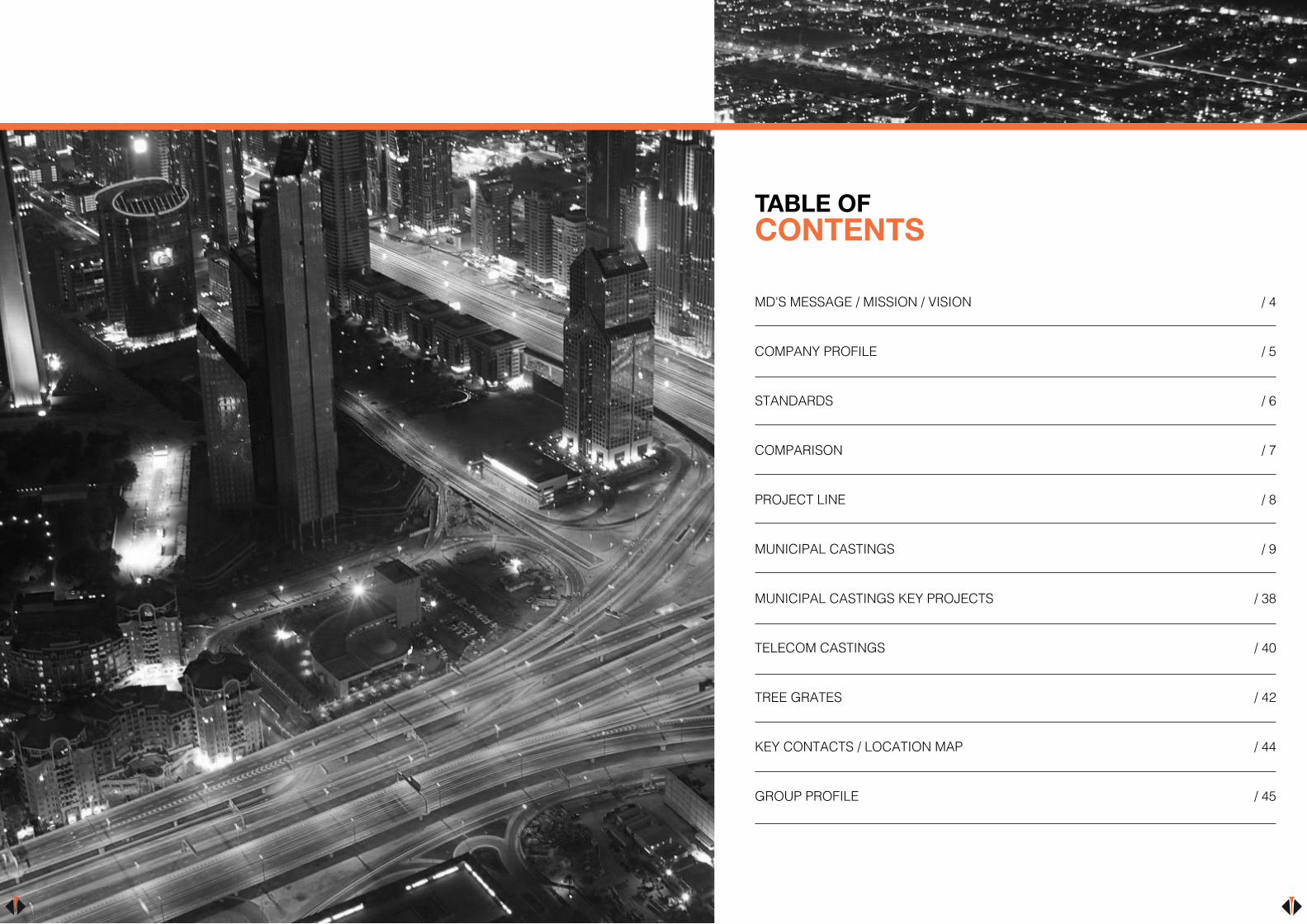
1. MATERIAL: DUCTILE IRON GRADE SG7/5002. MANHOLE COVER LOADING CLASS C250
AS PER EN 2015- 124
Plan View of Cover & Frame
Closed LiftingKeyholes- 4Nos
Prising Slots2-Nos
40x40mm Raised Pattern
Ribs
40x4
0MM
M-10SS Hex Bolt10-Nos.
30
8mm Dia Rubber Gasket
Sectional View of Cover & Frame
65
Sealing-
Ø180
65
12
9393 760x760mm C/O
1212
10
63012
818
051
946x946mm Over Base
051
20
ADMSTREET LIGHT
CODE CLEAR OPENINGA x B (mm)
OVER BASEB x C (mm)
FRAME DEPTHE (mm)
LOADING CLASS KN
PB - 4A 450 x 450 610 x 610 65 250
PB - 1 760 x 760 1040 x 1040 100 250
PB - 2 1200 x 1200 1480 x 1480 100 250
PB - 1N 760 x 760 946 x 946 65 250
PB - 2N 1200 x 1200 1440 x 1440 100 250
PB - 3A 750 x 750 915 x 915 100 400
PB - 6 900 x 900 10656 x 1065 100 400
PB - 2D 1200 x 1200 1480 x 1480 100 400
PULL BOXCOVER & FRAMEFEATURES Manufactured to EN - 124 - 2 (2015). Badging optional Paint as per customer’s requirement. - Denotes that the product is kitemarked.
MULTIPLECOVER & FRAME
CODE CLEAR OPENING(AXB) (mm)
OVER BASE (CXD) (mm)
FRAME DEPTH(E) (mm)
NO. OFCOVERS
LOADING CLASS KM
DI-2M-1290 1200 x 900 1290 x 1090 75 2 125
DI-2M-1290 1800 x 900 1890 x 1090 75 2 125
DIML-24 1230 x 796 1330 x 920 87 2 400
DIML-16 1200 x 600 1300 x 750 87 2 400
DIML-15 1200 x 900 1290 x 1080 90 2 400
DIML-1A 1800 x 900 1890 x 1080 90 3 400
DI-2M-1470 1400 x 700 1480 x 880 87 2 400
DI-02ST-1575 1500 x 750 1600 x 930 90 2 400
DI-2M-1210 1200 x 1000 1330 x 1190 90 2 400
DI-3M-1810 1800 x 1000 1940 x 1190 90 3 400
FEATURES Manufactured to EN - 124 - 2 (2015). Badging optional Paint as per customer’s requirement. - Denotes that the product is kitemarked.
PLAN VIEW OF COVER & FRAME
DUCAST
DUCTILE
DUCASTUAE
B
SECTIONAL VIEW
UAE
E
D
DUCASTUAE
A
CoverSeating
Area
C
EN 2- 124 D400DUCTILE DUCTILE
EN 2- 124 D400 EN 2- 124 D400
All Frame are coupled withS.S Hex Bolt with Nut

28 29
Slide out Direction
A
B
DU
CAST
UA
E
DU
CAST
UA
E
DU
CAST
UA
E
DU
CAST
UA
E
DU
CAST
UA
E
Covers & rebate to be filledwith concrete during
installations
M12 SS. HexBolt with nut.
SECTIONAL VIEW
B
10 10
Covers & rebate to befilled with concreteduring installations
Slide out Direction
Section A-A200 200L
CONTINUOUS TRENCH RECESSED PUMPING STATION COVER & FRAME2 PART TRENCH COVER
PIT CLEAR OPENING SPAN (B)
CLEAR OPENING(AXB) (mm)
OVER BASE (CXD) (mm)
DEPTH(E) (mm)
NO. OFCOVERS
LOADING CLASS
600 1300 x 600 1570 x 870 145 2 D400
750 1300 x 750 1570 x 1030 145 2 D400
900 1300 x x900 1570 x x1170 145 2 D400
600 1300 x 600 1570 x 870 145 2 F900
900 1980 x 900 2250 x 1170 145 2 F900
3 PART TRENCH COVER
600 1980 x 600 2250 x 870 145 3 D400
750 1980 x 750 2250 x 1030 145 3 D400
900 1980 x 900 2250 x x1170 145 3 D400
600 1980 x 600 2250 x 870 145 3 F900
900 2880 x 900 3150 x 1170 145 3 F900
4 PART TRENCH COVER
600 2690 x 600 2950 x 870 145 4 D400
750 2690 x 750 2950 x 1030 145 4 D400
900 2690 x 900 2950 x 1170 145 4 D400
600 2690 x 600 2950 x 870 145 4 F900
900 3780 x 900 4050 x 1170 145 4 F900
5 PART TRENCH COVER
600 3390 x 600 3690 x 870 145 5 F900
750 3390 x 750 3690 x 1030 145 5 D400
900 3390 x 900 3690 x 1170 145 5 D400
600 3390 x 600 3690 x 870 145 5 F900
900 4680 x 900 4950 x 1170 145 5 F900
CONTINUOUS AS PER REQUIREMENT
TRENCH COVERCONCRETE INFILL TRENCH COVERS
FEATURES Manufactured to EN - 124 - 2 (2015). Badging optional Paint as per customer’s requirement. - Denotes that the product is kitemarked.

30 31
CONCRETE INFILL TYPECOVER & FRAME
CODE CLEAR OPENING(AXB) (mm)
OVER BASE (CXD) (mm)
FRAME DEPTH(E) (mm)
NO. OFCOVERS
LOADING CLASS KM
PS-2 600 x 750 880 x 1030 145 1 400
PS-1 600 x 900 880 x 1180 145 1 400
DW-1 750 x 750 1000 x 1020 140 1 400
PS-3 750 x 900 1000 x 1180 145 1 400
DI-1-2P 1280 x 750 1550 x 1030 145 2 400
PS-1-3P 1980 x 700 2250 x 1030 145 3 400
PS-4 1320 x 900 1580 x 1180 145 2 400
PS-5 2020 x 900 2290 x 1180 145 3 400
DI-5E-1P 600 x 1050 870 x 1320 140 1 900
DI-5E-2P 1600 x 1200 1870 x 1470 140 2 900
DW-3 1300 x 1050 1570 x 1320 140 2 900
770m
m M
anho
le C
lear
Ope
ning
1020
mm
Ove
r Bas
e
140
165
200
750m
m P
it C
lear
Ope
ning
200
750mm Pit Clear Opening200 200
770mm Manhole Clear Opening
1020mm Over Base
Plan View of Cover & Frame
Section A-A
Section B-B
140
165
DU
CAST
UAE
BSlide out Direction
Frame leveling bolts toassisit installation
A
B
A
Covers & rebate to be filled with concrete during installations
FEATURES Manufactured to EN - 124 - 2 (2015). Badging optional Paint as per customer’s requirement. - Denotes that the product is kitemarked.

32 33
6 Part (6x6) recessed multispan cover with 5 removable support beam
PIT CLEAR OPENING (B)
6 Part (6x5) recessed multispan cover with 5 removable support beam
PIT CLEAR OPENING (B)
6 Part (6x4) recessed multispan cover with 5 removable support beam
PIT CLEAR OPENING (B)
6 Part (6x6) recessed multispan cover with 5 removable support beam
PIT CLEAR OPENING (B)
LOADING CLASS D400-PUMPING STATION RECESS COVER & FRAME PIT CLEAR OPENING (A X B)
COVER SIZE 750 X 750 MM
PIT
CLEA
R O
PEN
ING
( A X
B )
PIT
CLEA
R O
PEN
ING
( A X
B )
S/N AXB NO.COVER1600 .1X4 16701600 .2X6 25801600 .3X8 35001600 .4X10 44101600 .5X12 53302440 .6X6 16702440 .7X9 25802440 .8X12 35002440 .9X15 44102440 .10X18 53303260 .12X8 16703260 .13X12 25803260 .14X16 35003260 .15X20 44103260 .16X24 5330
S/N AXB NO.COVER4110 .17x10 16704110 .18X15 25804110 .19X20 35004110 .20X25 44104110 .21X30 5330
LOADING CLASS D400-PUMPING STATION RECESS COVER & FRAME PIT CLEAR OPENING (A X B)
COVER SIZE 900 X 900 MM
PIT
CLEA
R O
PEN
ING
( A X
B )
PIT
CLEA
R O
PEN
ING
( A X
B )
S/N AXB NO.COVER1890 .1X4 19701890 .2X6 30401890 .3X8 41101890 .4X10 51701890 .5X12 62302880 .6X6 19702880 .7X9 19702880 .8X12 19702880 .9X15 51702880 .10X18 62303870 .12X8 19703870 .13X12 30403870 .14X16 41103870 .15X20 51703870 .16X24 6230
750 1670 2580 3500 4410 5330
900
900
1890
2890
3870
1970 3040 4110 5170 6230
750
1600
2440
3260
4100
A
B
A
B
600
600
1300
1890
2680
3370
4060
1370 2140 2900 3470 4430
600
1300
2010
2710
3410
4110
900 2000 3090 4180 5260 6350
PIT
CLE
AR O
PEN
ING
(A)
Slid
e ou
t Dire
ctio
n
PIT
CLE
AR O
PEN
ING
(A)
Slid
e ou
t Dire
ctio
n
A
B
A
B
PIT
CLE
AR O
PEN
ING
(A)
Slid
e ou
t Dire
ctio
n
PIT
CLE
AR O
PEN
ING
(A)
Slid
e ou
t Dire
ctio
nLOADING CLASS D400-PUMPING STATION RECESS COVER & FRAME PIT CLEAR OPENING (A X B)
COVER SIZE 900 X 600 MM
PIT
CLEA
R O
PEN
ING
(AXB
)
PIT
CLEA
R O
PEN
ING
(AXB
)
S/N AXB NO.COVER1310 .1X4 20001310 .2X6 30901310 .3X8 41801310 .4X10 52601310 .5X12 63502010 .6X6 20002010 .7X9 30902010 .8X12 41802010 .9X15 52602010 .10X18 63502710 .11X8 20002710 .12X12 30902010 .13X16 41802710 .14X20 52602710 .15X24 6350
S/N AXB NO.COVER3410 .16x10 20003410 .17x15 30903410 .18x20 41803410 .19x25 52603410 .20x30 63504110 .21x12 20004110 .22x18 30904110 .23x24 41804110 .24x30 52604110 .25x36 6350
LOADING CLASS D400-PUMPING STATION RECESS COVER & FRAME PIT CLEAR OPENING (A X B)
COVER SIZE 600 X 600 MM
PIT
CLEA
R O
PEN
ING
(AXB
)
PIT
CLEA
R O
PEN
ING
(AXB
)
S/N AXB NO.COVER1300 .1X4 13701300 .2X6 21401300 .3X8 29001300 .4X10 34701300 .5X12 44301890 .6X6 13701890 .7X9 21401890 .8X12 29001890 .9X15 34701890 .10X18 44302680 .11X8 13702680 .12X12 21402680 .13X16 29002680 .14X20 34702680 .15X24 4430
S/N AXB NO.COVER3370 .16x10 13703370 .17x15 21403370 .18x20 29003370 .19x25 34703370 .20x30 44304060 .21x12 13704060 .22x18 21404060 .23x24 29004060 .24x30 34704060 .25x36 4430
600mm
600mm
900mm
600m
m
900mm
900m
m
750mm
750m
m
CONCRETE INFILL COVERSD400
FEATURES Manufactured to EN - 124 - 2 (2015). Badging optional Paint as per customer’s requirement. - Denotes that the product is kitemarked.

34 35
CONCRETE INFILL COVERSINSTALLATION OVERVIEW

36 37
Covers & rebate to be filled with concrete during installation
Wallbox Leveling Bolts
Frame leveling bolts to assisit installation
PIT CLEAR OPENING SPANWallbox Section (Front Elevation)
Wallbox Section (Front Elevation)
Removable Support “I” Beam
PIT CLEAR OPENING SPAN
Wallbox Leveling Bolts
CONCRETE INFILL COVERSINSTALLATION OVERVIEW
Multiple slide-out Covers and frames are manufactured and supplied with or without removable “I” Beams based on customer’s specific dimensional requirements of the pit opening. This is a general guideline for installation. Installation guide and assistance can be obtained from Ducast for specific needs.
All multipart slide out units consists multiple frame segments (Units with single end flange, double end flange, without flange, I-Beam Holders with double end flange and I-Beams fitted with L-Angle type segments as required) coupled together as a frame units using stainless steel fasteners. The contact surface of covers (Solid and recess type) and frames are machined at contact surfaces to ensure 100% metal to metal contact between cover and frame. Minimal uniform clearance between cover and frame as well as cover and cover water tightness with application of grease on the cover-frame contact surfaces prior to final assembly at site.
INSTALLATION GUIDE FOR MULTIPART COVER & FRAMES
Pre-installation assembly: Generally the frame parts are supplied dismantled and packed as set marked with identification for ease of transport. These frame parts needs to be assembled at site properly.
Place all connected parts in pre-built rebate with the I-Beam Holder in prebuilt wall box rebate. (For larger units the assembly needs to be done at the pit rebates itself)
Drop the I-Beam/L-Angle assembly one by one into I-Beam Holder of frame and ensure frame top is flush in line with top of the rebate all around
Ensure sufficient spacers under the frame parts ensure the top level of the frame is in flush with top of rebate using string line. Use steel or cement sheet for as spacers so that they will not crumble with under frame weights
All the frame cover seating area needs to be in flush and linearly aligned and sprit levelled.
Ensure the inner opening length of frame at top is same when measured diagonally on both directions
Ensure that the I-Beam Holder seating portion do not protrude in to clear opening and stand at 900 to its base.
Use rigid wedge type spacer in between the frame parts and the side wall of the rebate wall to avoid twist of frames.
Clean all the debris from all vertical seating sections of the frame parts
Installation of covers: Clean and remove any debris on the covers on sides and seating area.
Drop the covers in to frame in proper direction for one row of covers preferably in middle.
(Referring the slope of frame side and slope on the side of the cover)
Then place the covers at end rows. Place the remaining covers. Each time after placement of 1 set of covers ensure the
leveling bolts (on frame & I-Beam Holder) are adjusted if required.
Ensure the covers are fit well and ensure the metal to metal to contact of cover with frame and non- rocking by walking over.
Ensure proper alignment without gaps between cover and frame as well as cover & covers.
Retighten all the frame coupling bolts. Slight tapping may be required on I Beams as well frame parts for proper alignment.
Shuttering Remove some covers and place the shuttering inside the perimeter of the pit.
The shuttering needs to be approximately 10mm higher than the bottom of the frame.
Replace all the covers and ensure proper alignment without gaps between cover and frame as well as cover & cover.
Mask all the keyways of covers. Tight the loosely pre fastened I-beam Holder lid in to I-Beam.
Concreting Pour concrete (Preferably C45 Grade) in between frame till it reaches the shuttering and tamp to avoid any voids.
Pour the concrete in to Integrated L-Angle gap till it reach the I-Beam Holder Lid and tamp.
Fill concrete in I-Beam Holder Lid. Pour concrete on covers in case of recessed covers.
Application of greaseAfter curing of concrete, remove cover one the other and apply grease generously on the sides and seating potion of both cover and frame and re-fix the cover
Note: 1. For identification of components always refer to the drawing of the unit.2. If shown on the drawing anchoring of the frame unit to be done as indicated on the drawing.

MUNICIPAL CASTINGSKEY PROJECTS
PROJECT DETAILS● Dubai International Airport● Various roads & infrastructure project under- RTA / ADSSC / ADDC / DEWA / ADEWA / DUBAI● Al Maktoum International Airport, Abu Dhabi Airport● Sharjah International Airport● New Doha International Airport● Khalifa Port● Muscat International Airport● Salalah Airport● Pearl Qatar
38 39

40 41
Telecommunication Cover & Frame Telecommunication Recess Cover & Frame
TELECOM CASTINGS
TELECOMMUNICATIONCOVER & FRAME
CODE CLEAR OPENINGA x B (mm)
OVER BASE C X D (mm)
FRAME DEPTH E (mm)
NO. OFTRIANGULAR
COVERS
LOADING CLASS KN
CW - 1 590 x 590 745 x 745 160 2 400
CW - 2 1220 x 696 1374 x 850 160 4 400
CW - 3 1830 x 696 1984 x 850 160 6 400
CW - 4 920 x 465 1120 x 665 97 Single Pieces 400
FEATURES Manufactured to EN - 124 - 2 (2015). Badging optional Paint as per customer’s requirement. - Denotes that the product is kitemarked.
TELECOMMUNICATION RECESSED COVER & FRAME
CODE CLEAR OPENINGA x B (mm)
OVER BASEC x D (mm)
FRAME DEPTHE (mm)
RECESSED DEPTH F (MM)
NO. OFTRIANGULAR
COVERS
LOADING CLASS KN
CW-2RC80 1220 x 696 1374 x 850 160 80 4 400
CW-3RC80 1830 x 696 1984 x 850 160 80 6 400
CW-4RC10 920 x 465 1110 x 655 130 100 Single Piece 400
FEATURES Manufactured to EN - 124 - 2 (2015). Badging optional Paint as per customer’s requirement. - Denotes that the product is kitemarked.
SECTIONAL VIEW
PLAN VIEW OF COVER & FRAME
DUC
AST
UAE
B D
A
C
FE
DUC
AST
UAE
DUC
AST
UAE
DUC
AST
UAE
DUC
AST
UAE
SECTIONAL VIEW
PLAN VIEW OF COVER & FRAME
DUC
AST
UAE
B D
A
C
FE
DUC
AST
UAE
DUC
AST
UAE
DUC
AST
UAE
DUC
AST
UAE
B
B
A A
M
PLAN VIEW OF COVER &FRAME
SECTION-AA
Section-BB
C
A
E
DB
E
M12 dia Hex bolt withlock nut (8 nos. )
Covers to be open in Sl. No (1,2,3&4) wise and, All covers are interlock with each other.
Cover 1-
Cover 2-
Cover 3-
Cover 4-
E
N 1
24-2
D 4
00
DUCAST UAE
EN 2
- 124
D 4
00DU
CAST
UAE
EN 1
24 -2
D 4
00DU
CAST
UAE
EN 124 -2 D 400DUCAST UAE
EN 124 -2 D 400DUCAST UAE
LOC
K
OL
B
B
A A
M
PLAN VIEW OF COVER &FRAME
SECTION-AA
Section-BB
C
A
E
DB
E
M12 dia Hex bolt withlock nut (8 nos. )
Covers to be open in Sl. No (1,2,3&4) wise and, All covers are interlock with each other.
Cover 1-
Cover 2-
Cover 3-
Cover 4-
E
N 1
24-2
D 4
00
DUCAST UAE
EN 2
- 124
D 4
00DU
CAST
UAE
EN 1
24 -2
D 4
00DU
CAST
UAE
EN 124 -2 D 400DUCAST UAE
EN 124 -2 D 400DUCAST UAE
LOC
K
OL

42 43
Ductile Iron Tree Grating
TREE GRATES CODE CLEAR OPENING
A (mm)OVER BASEB x C (mm)
FRAME DEPTHE (mm)
DUC-TREE-05 1500 x 1500 600MM DIA 30
DUC-SA-TREE-01 1200 x 1200 600MM DIA 50
CI-TREE- 1010 1000 x 1000 750MM DIA 30
DUC-SA-TREE-2020 2000 x 2000 750MM DIA 40
DUCTILE IRON TREE GRATING
FEATURES Paint as per requirement.
1200mm
1215mm
50x50x6mm"L" angle
1116
mm
50
1215
mm
Sectional side View B-B
600mm Opening
1116mm Opening
AnchoringLugs
1200
mm
Tree Grill will be inDuctile Iron -2Piece
Double TriangularForm finish Epoxy
Coated
Frame will be in Mild Steel -2PartTriangular form Hot DipGalvanized finish
Plan View
Sectional Front View A-A
1200
mm
1200mm
A
B
Ø 600m
m O
pening
1215
mm
A
B
44 50
44
1500
1500
Ø800
mm
Clea
r Ope
ning
Plan View of Tree Grill with Frame1518
1518
Tree Grillwill be two part
Mild steel Fabricated Frame "L" Angle 30x30x6mm-2 Nos. FinishHot Dip Galvanized
Section-AA
30
DUCAST UAE
DUCAST UAE
1458
1518
A
2525
50x8mm Thick flat for achoring purpose8-Nos
A
2000mm
2000
mm
1,000
1,00
0
Tree Grill will be 4 part without frame
Gratings are coupled with SS Hex Bolts and nuts- 8Nos
20 40
500mm Dia C/O
Sectional front View
Plan View of Tree Grill
Ø500
DUCAST-UAE DUCAST-UAE
DUCAST-UAE
Ø150
Ø150
150mm Dia Lighting hole -2 Nos.
DUCAST-UAE
1000
1000
Tree Grill will be 2 part with frame
Plan View of Tree Grill
Sectional front View
700mm Dia C/O
1000X1000mm Over BaseProvision for M16Bolt & Nut .
180mm Dia Ø180
Lighting hole 1- Nos.
25
30
Flanges are coupledwith M10 SS Hex
bolts and Nuts
50x8mm Thick flat for achoring purpose8-Nos
Mild steel Fabricated Frame "L" Angle 30x30x5mm2- Nos. FinishHot Dip Galvanized
1013
mm
O/B
1013mm O/B
Ø700MM C/O
44 45
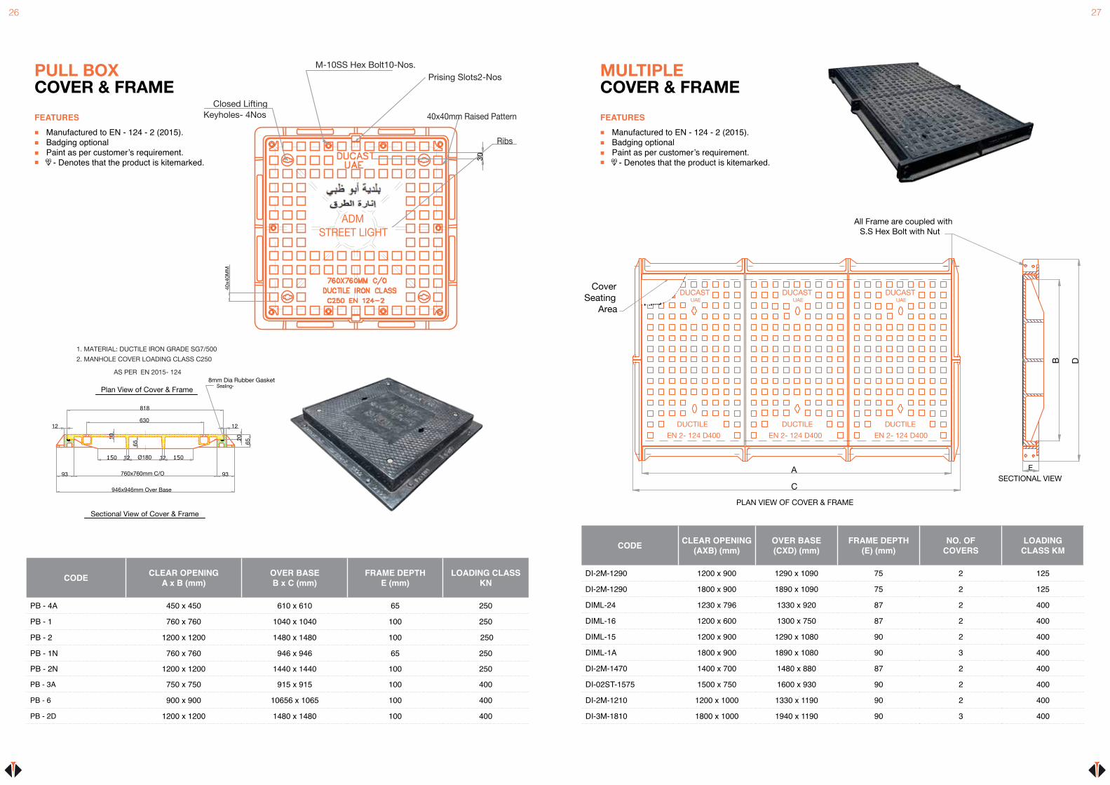
KEYCONTACTS
Mr. Lalit Taurani Managing Director [email protected]
Mr. Amal Banerjee General Manager [email protected]
Mr. Balaji K Quality Control Manager [email protected]
Mr. Jitendra Sangtani Sales Manager [email protected]
Mr. Prakash Chandwani Sales Manager - Exports [email protected]
Mr. Shahid Perveiz Asst. Sales Manager [email protected]
Mr. Nayyar Kamil Sales Manager (Saudi Arabia) [email protected]
Mr. Nazar Abbas Senior Sales Executive [email protected]
Mr. Manesh Satave Sales Executive [email protected]
Mr. Viswa Kumar Sales Executive - Northern Emirates [email protected]
Mr. Mushtaq Shaikh Sales Executive (Abu Dhabi) [email protected]
Nakul Kulkarni Sales Coordinator [email protected]
Nilesh Sachdev Sales Coordinator [email protected]
Logistics / Dispatch [email protected] / [email protected]
LOCATIONMAP
LOCAL CONTACTS
GROUPPROFILE
TAURANI HOLDINGS LTD is a multinational conglomerate headquartered in Dubai, United Arab Emirates. It operates in four continents with more than 2,400 employees worldwide THL was founded in 1976 as a group of manufacturing, trading and servicing companies catering to a vast multitude of sectors across various markets.
With annual turn over of US$200 Million, the group has eventually ventured into every trade arena through well-defined business strategies. An able leadership and a highly dedicated work force across the group are the key elements that engineer its evolution.
As a global business conglomerate, the group’s ability to understand, innovate and operate in a multicultural world ensures its long-term sustainability and, specifically, impacts its ability to meet the group’s underlined growth trajectory.

47
NOTES

OBC
DUCAST FACTORY L.L.C P.O Box 28480, Dubai - UAE TEL: +971 4 3470777 FAX: +971 4 3470707 EMAIL: [email protected]
ducastfactory ducastfactory ducast-factory-l-l-c