Embed Size (px)
Citation preview

366 • Renewable energy engineering and technology
Cheaper alternatives to conventional solar water heaters
As conventional solar water heaters have higher initial costs as compared to
commercial fuel-based water heaters (for example, electric geysers), several
attempts have been made to design cheaper systems. Some of these are
discussed below.
Collector-cum-storage water heater
This is a rectangular or cylindrical metal box (usually galvanized iron or mild
steel to keep the cost low), one side of which is painted black. The metal box is
kept inside a wooden enclosure (or a similar low-cost enclosure) with one side
open for fixing a cover glass (Figure 6.25).
If the height of the metal box is 50 mm, it can hold 50 litres/m2 of
collector area. On the basis of a rough calculation for a 24-hour average
radiation level of 200 W/m2 and an average collector efficiency of 25%, a
temperature rise of about 20 ºC can be obtained for such a box-type col-
lector. If the initial temperature of water is 30 ºC, the final water
temperature would be 50 ºC, which is quite adequate for bathing, etc. Such
Figure 6.25 Simple collector-cum-storage solar water heater

Solar thermal engineering • 367
box-type water heaters have been investigated in India at CAZRI (Central
Arid Zone Research Institute), Jodhpur, and at TER I.
Shallow solar ponds
SSPs (shallow solar ponds) have long been considered potential alternatives for
conventional flat plate collectors. One of the earlier applications of SSPs was
in desalination (Hodge, Thompson, Groh, et al. 1966). An SSP prototype
facility was built and operated to supply hot water to the Sohio Uranium Mill
near Grants, New Mexico (Dickinson, Clark, and Iantuore 1976). A compact
SSP for hot water preparation for military and recreation purposes was
reported by Kudish and Wolf (1979).
SSP consists of a shallow bed of water contained within two plastic layers
– black plastic layer at the bottom and transparent layer at the top – with
suitable insulation and container box, and another glazing to reduce heat
losses (Figure 6.26).
The temperature build-up over the day can be obtained by solving the
equation
( ) ( )MCdT
dtA G A U T Tp
pc c L p a = τα − −( ) ...(6.84)
where (MC)p is the mass-specific heat product of water in the pond, T
p is the
temperature of water at a given time t, Ac is the area of the pond exposed to
sunlight, and (τα) and UL are same as those in flat plate collectors. As fins and
Figure 6.26 Sectional view of shallow solar pond

368 • Renewable energy engineering and technology
fluid flow are not involved, F’ and FR are unity. A theoretical and experimental
investigation of SSPs with continuous heat extraction has been proposed
(Kishore, Gandhi, and Rao 1986). A domestic solar water heater based on SSP
with a heat pipe heat exchanger, shown in Figure 6.27, has been studied experi-
mentally (Gandhi and Kishore 1983).
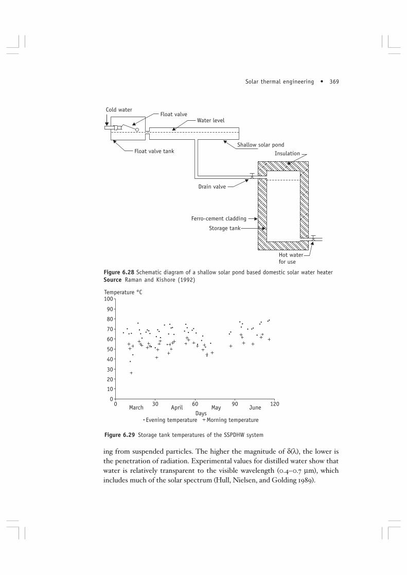
A portable SSP water heater has also been proposed (Kishore, Ranga
Rao, and Raman 1987). Temperature increments of up to 30 ºC over the day
have been reported. An SSP-DHW (shallow solar pond based domestic hot
water) system, where the hot water can be drained down into an insulated stor-
age tank, has been tested for long-term performance in Delhi (Raman and
Kishore 1992) (Figures 6.28 and 6.29).
Salinity gradient solar ponds
When sunlight falls on a water body such as a pond or a lake, part of the en-
ergy is reflected from the surface and the rest is transmitted. For a given
wavelength λ of light, the transmission τ (λ, l) of a ray through a distance l in
water can be represented as
τ λδ λ
, expll( ) −
( )⎛
⎝⎜
⎞
⎠⎟ = ...(6.85)
where δ(λ) is the characteristic wavelength-dependent attenuation length.
Attenuation of light results from absorption, molecular scattering, and scatter-
Figure 6.27 Shallow solar pond based domestic solar water heater
Solar thermal engineering • 369
ing from suspended particles. The higher the magnitude of δ(λ), the lower is
the penetration of radiation. Experimental values for distilled water show that
water is relatively transparent to the visible wavelength (0.4–0.7 µm), which
includes much of the solar spectrum (Hull, Nielsen, and Golding 1989).
Figure 6.28 Schematic diagram of a shallow solar pond based domestic solar water heaterSource Raman and Kishore (1992)
Figure 6.29 Storage tank temperatures of the SSPDHW system

370 • Renewable energy engineering and technology
Due to the absorption of radiation, the temperature of a given layer of
water increases and the heated water tends to rise to the surface through
convection. For a layer of thickness l and temperature difference between the
top and bottom layer temperatures ∆T, Rayleigh showed that convection does
not set in until ∆T reaches a critical value given by the following equation
Rg T l
kTT
= = =αν
π∆ 3 4274
657 5. ...(6.86)
where RT is the thermal Rayleigh number, g is the acceleration due to gravity, α
is the thermal expansion coefficient, ν is the kinematic viscosity, and kT is the
thermal diffusivity.
In normal circumstances, convection would set in depending on the
magnitude of the Rayleigh number, but if one can create a ‘density gradient’,
in which the bottom portion of the layer has higher density than the top,
convection can be suppressed even if ∆T is higher than the critical value. If
convection is suppressed, the solar energy entering the pond is ‘trapped’,
resulting in higher temperatures of the lower layers of water in the pond, from
which heat can be extracted for useful purposes. This is the principle of
operation of a solar pond. The pond thus becomes a solar collector with
built-in storage, and as no expensive metals are used, it is potentially cheaper.
Practical solar ponds are based on the fact that saline water has higher density
as compared to pure water. The density of a salt solution can be represented as
ρ = ρ0 [1 – C
T(T – T
0) + C
s(S – S
0)] ...(6.87)
where ρ0 corresponds to a reference state; C
S and C
T are coefficients; and S is
the salinity expressed as concentration or percentage of salt in the saline solu-
tion. The change in density can be calculated as follows.
∂∂
−ρ ρT
CT = 0 ...(6.88)
∂∂ρ ρS
Cs = 0 ...(6.89)
and
∂∂
∂∂
∂∂
∂∂
∂∂
ρ ρ ρx S
Sx T
Tx
= + ...(6.90)
where x is the vertical co-ordinate increasing downward. For densities to
remain stable, it is necessary that

Solar thermal engineering • 371
∂∂
>ρx
0 ...(6.91)
Substituting from Equations 6.88 and 6.89 and re-arranging, we get
RC S
xC T
x
s
T
ρ = ∂
∂( )∂
∂( ) > 1 ...(6.92)
This is the criterion for static stability and provides the salinity gradient
values for a given temperature gradient. In real ponds, there is another
criterion called dynamic stability criteria, in which both thermal and mass
diffusivity are considered in the double-diffusive system (Hull, Nielsen, and
Golding 1989).
In real solar ponds, there are three distinct zones: UCZ (upper
convective zone) or the surface zone, NCZ (non-convective zone) or the
gradient zone, and LCZ (lower convective zone) or the storage zone. A sche-
matic diagram of the solar pond is shown in Figure 6.30 (a).
The UCZ is formed due to wind effects, evaporation, etc., and can be
maintained at a thickness of about 30–50 cm. The NCZ has a thickness of
1–1.5 m and the LCZ has a thickness of about 1.5 m. The density gradient
can be created artificially using a diffuser method (Kishore and Kumar
1996). Temperatures in LCZ and NCZ build up rapidly once the salinity gra-
dient is established in a clear pond. The rise of temperature in the LCZ for
the 6000 m2 solar pond of Bhuj is shown in Figure 6.30 (b).
With convection suppressed, NCZ can be treated as a transparent con-
ducting solid with a heat generating source (solar radiation absorbed).
Figure 6.30a Schematic diagram of the solar pond

372 • Renewable energy engineering and technology
Choosing a co-ordinate system with x = 0, corresponding to the surface of the
pond, the solar radiation at depth x is given by
G(x) = Gs g(x) ...(6.93)
where Gs is the radiation immediately below the surface and is given by
Gs = G
0 (1 – a) ...(6.94)
where Go is the global radiation on a horizontal surface and a is the albedo of
the surface, which depends on the incident angle.
The one-dimensional unsteady heat conduction equation for the NCZ is
ρCTt
kT
xGxp
∂∂
∂∂
− ∂∂
= 2
2 ...(6.95)
The initial condition can be taken as T = To at the start-up of the pond.
The two boundary conditions required to solve the above equation are
obtained by heat balance on UCZ and NCZ. With a suitable functional form
Figure 6.30(b) Temperature history of the storage zone for the 6000 m2 solar pond in BhujSource Kishore and Kumar (1996)
Month/Day

Solar thermal engineering • 373
for G(x), Equation 6.95 can be solved using numerical techniques. One general
method of solving it is by applying the Crank–Nicolson method (Joshi and
Kishore 1985a; Joshi, Kishore, and Rao 1984).
A useful expression for obtaining the efficiency of the solar pond can
be derived by assuming pseudo-steady state conditions in which δT/δt = 0.
Equation 6.95 can then be written as
kd Tdx
ddx
G x2
2 = ( )( ) ...(6.96)
An energy balance for UCZ gives
Q G g x kdTdxs s
x x
= [ ( )]1 11
− +=
...(6.97)
where Qs is the sum of heat losses (convective, radiative, and evaporative)
from the surface and x1 is the depth of UCZ. A similar equation for LCZ can
be written as
Q G g x kdTdx
Qu sx x
b= ( )22
− −=
...(6.98)
where Qu is the useful heat extracted, Q
b is the bottom loss to the ground, and
x2 corresponds to the interface between NCZ and LCZ. Equation 6.96 can be
solved using the boundary conditions of Equations 6.96 and 6.98 (Kishore and
Joshi 1984; Kooi 1979).
Qu = G
s(τα) – U
t (T
b – T
s) – Q
b...(6.99)
where
τα( )−
∫=
g x dx
x xx
x
( )1
2
2 1
...(6.100)
and
Uk
x xt =2 1− ...(6.101)
Qs and Q
b can be related to the ambient and ground conditions, respec-
tively. Taking assumed or measured profiles for g(x), thermal efficiencies of
solar ponds can be obtained. However, such results are applicable only for
yearly average performance (Joshi and Kishore 1986).

374 • Renewable energy engineering and technology
The attenuation function g(x) had been fitted to various functional
forms. The Rabl–Nielsen model is expressed as
g x r xi i ri
( ) exp sec= −( )∑=
µ θ1
4
...(6.102)
where ri and µ
i are the constants for a particular seawater and θ
r is the angle of
refraction.
Bryant and Colbeck proposed a simple two-parameter model
g(x) = a–b ln (x sec θr) ...(6.103)
The one-parameter model proposed by Hawlader and Brinkworth is
expressed as
g(x) = (1–F)exp[–µ(x–δ)secθr] ...(6.104)
where F is taken as 0.4 and δ as 0.06 m. The effect of using different attenua-
tion models on performance predictions has been studied by Joshi and
Kishore (1985b).
Considerable work on solar ponds has been done worldwide, including
India (Rao, Kishore, and Vaja 1990). The largest solar pond in Asia, the
6000 m2 solar pond at Bhuj, India, operated in an industrial environment and
supplied process hot water to the Kuchch dairy for more than two years
(Kishore and Kumar 1996). The solar pond at Pondicherry is producing
electricity since 2004. A very large number of applications, including
desalination, bromine recovery, manufacture of magnesium chloride,
improved salt production, and so on have been identified for coastal areas in
India.
Evacuated tube collectors
Evacuated or vacuum tube collectors are fast becoming popular in the world
market. Emmett first proposed the concept of an evacuated tube collector
in 1909. With recent advances in vacuum and sealing technology and the
development of selective coating on glass surfaces, the evacuated tube
collectors are now mass-produced in various countries.
Essentially, these are based on the Dewar vacuum flask concept, wherein
the convective losses from the collector surface are reduced by providing
vacuum around the absorber. There are two major design configurations in
evacuated tube collectors
Single-glass tube
Double-glass tube

Solar thermal engineering • 375
Figure 6.31 Evacuated tube collector designsSource Goswami, Kreith, and Kreider (2000)
Single-glass tube evacuated collectors
In single-glass tube collectors, either a heat pipe is used to extract heat from
the collector or a simple U-tube with fin is provided to circulate the fluid
(Figure 6.31 a, b). The metal tube or heat pipe tube and the glass tube covering
it are hermetically sealed to form a vacuum tight joint. The air between
the gap is extracted from the other end using a vacuum pump and then the
end is sealed. Activated barium getter is provided to absorb the gases, which
can diffuse through the glass tube. Sometimes a small ripple reflector is pro-
vided below the collector to improve the concentration of the solar
radiation from below. The sealing of the glass to metal joint is the most
important area in these collectors. These types of collectors have a few advan-
tages as listed below.
Higher heat transfer efficiencies.
No fluid present inside the glass collectors.
Easy to use as an indirect heating element, especially when the outside
conditions are freezing or hard water is to be heated.
Double-glass tube evacuated collectors
Double-glass tube collectors (Figure 6.31c) are easy to manufacture but are
less efficient than single-glass tube collectors. They have two glass tubes

376 • Renewable energy engineering and technology
attached to each other at one end while the other end of both the tubes is
closed. The space between them is evacuated and a selective absorbing coating
is applied on the outer surface of the inner tube. They can be used directly to
heat water stored in the inner tube and are commonly used in domestic water
heating systems. Domestic solar water heating systems based on double-glass
tube collectors are now commonly available in the Indian market.
Evacuated tube collector thermal analysis
Conductive heat transfer between two surfaces having low-pressure gas in the
interim space is given by the following equation (Goswami 2006).
ql = k∆t/(g + 2p) ...(6.105)
where ql is the heat loss, k is the constant, ∆t is the temperature gradient, g is
the gap between surfaces, and p is the mean free path of molecules.
For air, the mean free path at atmospheric temperature and pressure is
about 70 µm. If 99% air is removed from a tubular collector, the mean free
path increases to 7 mm, and conduction heat transfer is almost unaffected.
However, the mean free path increases to 7 cm at 10–7 torr, which is
substantially greater than the heat transfer path length (gap between the glass
tubes), which is of the order of 20 mm. This reduces the conductive heat
transfer substantially.
The relative reduction in heat transfer as a function of the mean free
path can be derived from Equation 6.105
qq p g
vac
l
= 1
1 2+ / ...(6.106)
where ql is the conductive heat transfer if convection is suppressed and q
vac is
the conductive heat transfer under vacuum.
The effective heat gain of the evacuated tubular collector based on
the aperture area can be expressed as follows (Goswami, Kreith, and Kreider
2000b).
q GAA
U T TAAu eff
tb
cL abs a
abs
c
= (τα)1 1
− −( ) ...(6.107)
where qu is the useful heat gain (W/m2) and G
eff is the effective solar radiation,
both intercepted directly and after reflection from the back reflector
(reflected radiation is typically 10%) (W/m2); Atb
is the projected tube
area (m2), Ac1
is the total collector area (m2), UL is the overall heat loss

Solar thermal engineering • 377
coefficient (W/m2K), Tabs
is the absorber temperature (ºC), Ta is the ambient
temperature (ºC), and Aabs
is the projected area of the absorber (m2).
Bekey and Mather have shown that a tube spacing of one diameter apart
maximizes the energy output (Goswami, Kreith, and Kreider 2000).

392 • Renewable energy engineering and technology
Nomenclature
a Albedo of the surface
A Aperture area of the cooker (m2)
Ac
Area of the collector (m2)
Ar
Receiver area (m2)
Ac1
Total collector area (m2)
Atb
Projected tube area (m2)
Aabs
Projected area of the absorber (m2)
A1/A
2Area ratio
b Width (m)
bo
Incident angle modifier coefficient
B Radiance (W)
C Concentration ratio
Cb
Bond conductance (W/m)
Cr
Ratio of (MC)w/(MC)’
w
d Diameter (m)
De
Equivalent diameter (m)
Di
Inside tube diameter (m)
E2/E
1Flux concentration ratio
f’ Factor
F Fin efficiency
F’ Collector efficiency factor
g Gravitational acceleration (m/s2)
Go
Global radiation on a horizontal surface (W/m2)
Gs
Radiation immediately below the surface (W/m2)
Gs,c
Solar constant
Geff
Effective solar radiation (W/m2)
Gsun
Radiosity
h1, h
2Convective heat transfer coefficient (W/m2K)
hbf
Convective heat transfer coefficient from the bottom plate to the air
(W/m2K)
hfi
Fluid heat transfer coefficient (W/m2K)
hpf
Convective heat transfer coefficient between the plate and the fluid
(W/m2K)
hr,pb
Radiative heat transfer coefficient between the collector plate and the
bottom plate (W/m2K) in air heater
I Irradiance, W/m2
k Equivalent number of velocity heads lost by the flow in passing through
bends, thermal conductivity (W/mK)

Solar thermal engineering • 393
kT
Thermal diffusivity (m2/s)
K Extinction coefficient of the medium
KτaIncident angle modifier
l Thickness of water layer (m), length, m
L Length of the collector plate (m)
L Cover plate thickness (m)
m Fluid flow rate for a single tube (kg/s)
MC Mass-specific heat product of water in the pond (J/K)
n1, n
2Refractive indices of the media
Nu Nusselt number
p Mean free path molecule (m)
q1
Conductive heat transfer if convection is suppressed (W)
qu
Useful heat gain (W)
qp–c
Heat loss, W
qload
Useful energy supplied to the load from the storage (W)
qvac
Conductive heat transfer under vacuum (W)
Qb
Bottom loss to the ground (W)
QL
Heat lost (W)
Qs
Sum of heat losses (W)
Qu
Useful heat (W)
r Reflectance of unpolarized light
rpa
Parallel component of the unpolarized light
rpp
Perpendicular component of the unpolarized light
Re Reynolds number
RT
Thermal Rayleigh number
S Salinity (kg/m3)
S Solar radiation absorbed by the fin (W/m2)
t Time (s)
T Temperature
u Velocity (m/s)
Ub
Heat loss coefficient from the bottom of the collector (W/m2K)
UL
Overall heat loss coefficient (W/m2K)
Ut
Top loss coefficient (W/m2K)
(UA)tank
Product of the overall heat transfer coefficient and the surface area of
the tank (W/K)
x x-coordinate
y y-coordinate
Φ Radiant flux (W)
θ Angle
.
.
.

394 • Renewable energy engineering and technology
τ Transmittance
τpa
Transmittance for the parallel component
τpp
Transmittance for the perpendicular component
ρ Reflectance
ρd
Diffuse reflectance
α Absorptance, thermal expansion coefficient
γ Wavelength (m)
β Collector tilt
δ Fin thickness (m)
δi
Thickness of the insulating material (m)
δc
Thickness of a copper plate (m)
η Efficiency
ηo
Optical efficiency
ν Kinematic viscosity (m2/s)
δ(λ) Characteristic wavelength-dependent attenuation length (m)
Ω Solid angle
References
Brandemuehl M J and Beckman W A. 1980Transmission of diffuse radiation through CPC and flat plate collector glazingSolar Energy 24(511)
Close D J. 1962The performance of solar water heaters with natural circulationSolar Energy 6(33)
Dickinson W C, Clark A F, and Iantuore A. 1976in Proceedings of the International Solar Energy SocietySolar Energy Conference 5(117)
Duffie J and Beckman W A. 1991Solar Engineering of Thermal ProcessesNew York: John Wiley and Sons, Inc.
Gandhi M R and Kishore V V N. 1983Experimental performance of shallow solar pond of novel designIn Proceedings of the Sixth Miami International Conference on Alternative Energy Sources [SixthMiami International Conference on Alternative Energy Sources, Florida]
Garg H P, Mullick S C, and Bhargava A K. 1985Solar Thermal Energy StorageReidel Publishing Company

Solar thermal engineering • 395
Goswami Y D, Kreith F, and Kreider J N. 2000Principles of Solar Thermal Engineering, Second editionPhiladelphia: Taylor and Francis
Grossman G, Shitzer A, and Zvirin Y. 1977Heat transfer analysis of a flat-plate solar energy collectorSolar Energy 19: 493–502
Gupta C L and Garg H P. 1967Performance studies of solar air heatersSolar Energy II(25)
Gupta C L and Garg H P. 1968System design in solar water heaters with natural circulationSolar Energy 12(163)
Hodge C N, Thompson T L, Groh J E, Frieling D H. 1966Progress Report 194USA: Office of Saline Water Research and Development
Hull J R, Nielsen C E, and Golding P. 1989Salinity-gradient Solar PondsBoca Raton, Florida: CRC Press
IS 12933. 2003Solar flat plate collector-specificationsNew Delhi: Bureau of Indian Standards
Joshi V and Kishore V V N. 1985aComputer simulation of the performance of the solar pondReg. J Energy Heat Mass Transfer 7(2): 97–106
Joshi V and Kishore V V N. 1985bA numerical study of the effects of solar attenuation modelling on theperformance of solar pondsSolar Energy 35(4): 377–380
Joshi V and Kishore V V N. 1986Applicability of steady state equations for solar pond thermal performancepredictionsEnergy II(8): 821–827
Joshi V, Kishore V V N, and Rao K S. 1984A digital simulation of non-convecting solar pond for Indian conditionsRenewable Energy Sources: International Progress edited by T. Nejat VezirogluElsevier, pp. 207–220
Kaushika N D and Sumathy K. 2003Solar transparent insulation materials: a reviewRenewable and Sustainable Energy Reviews 7: 317–351

396 • Renewable energy engineering and technology
Kishore V V N and Joshi V. 1984A practical collector efficiency equation for non-convecting solar pondsSolar Energy 33(5): 391–395
Kishore V V N and Katam S. 1987Flat Plate Collector Testing—an overviewSESI Journal 1: 11–17
Kishore V V N and Kumar A. 1996Solar pond: an exercise in development of indigenous technology at KutchEnergy for Sustainable Development III (1)
Kishore V V N, Gandhi M R, and Rao K S. 1984Analysis of flat-plate collectors charged with phase-changing fluidsApplied Energy 17: 133–149
Kishore V V N, Gandhi M R, and Rao K S. 1986Experimental and analytical studies of shallow solar pond system withcontinuous heat extractionSolar Energy 36(3): 245–256
Kishore V V N, Ranga Rao V V, and Raman P. 1987A portable shallow solar pond water heaterSolar and Wind Technology 4(2): 201–204
Kishore V V N, Gandhi M R, Marquis Ch, Rao K S. 1984Testing flat plate collectors charged with phase-changing fluidsApplied Energy 17: 155–168
Kishore V V N, et al. 1986Development of solar (thermal) water pump prototype – an Indo SwissexperienceSolar Energy 36(3): 257–265
Kooi C F. 1979The steady state salt gradient solar pondSolar Energy 23: 37–45
Kudish A I and Wolf D. 1979A compact shallow solar pond hot water heaterSolar Energy 21(317)
Maru L V, Kishore V V N, and Gomkale S D. 1986A roof collector for industrial hot water productionEnergy II(7): 651–657
Mullick S C, Kandpal T C, and Saxena A K. 1987Thermal test procedure for box-type solar cookerSolar Energy 39: 353–360

Solar thermal engineering • 397
Ong K S. 1974A finite-difference method to evaluate the thermal performance of a solar waterheaterSolar Energy 16: 137–147
Pytlinski J T. 1978Solar energy installations for pumping irrigation waterSolar Energy 21: 255–262
Raman P and Kishore V V N. 1992Performance of a shallow solar pond based domestic hot water system (100 LPD), inNorth Indian Climate[Paper presented in the National Seminar on Urban–Rural Alternative EnergyManagement, Pondicherry University, 7–8 February 1992]
Rao D P and Rao K S. 1976A solar water pump for lift irrigationSolar Energy 18: 405–411
Rao K S, Kishore V V N, and Vaja D (eds). 1990Solar pond: scope and utilisationVadodara: Gujarat Energy Development Agency
Sukhatme S P. 1984Thermal Energy Storage. Solar Energy – principles of thermal collection and storageNew Delhi: Tata McGraw-Hill Publishing Company Ltd
Whillier A. 1963Black painted solar air heaters of conventional designSolar Energy 8(31)
Whillier A and Saluja G. 1965Effects of materials and of construction details on the thermal performance of solarwater heatersSolar Energy 9(21)
Winter C J, Sizmann R L, and Vant-Hull L L (eds.). 1991Solar Power Plants: fundamentals, technology, systems, economicsNew York: Springer-Verlag
Zakhidov R A, Umarov G Y A, and Weiner A A. 1992Theory and calculation of applied solar energy concentrating systemsVadodara: Gujarat Energy Development Agency