Embed Size (px)
Citation preview

Parallel Programming LaboratoryUniversity of Illinois at Urbana-Champaign
Charm++Finite Element Method (FEM) Framework
Manual
Initial version of Charm++ FEM Framework was developed by Milind Bhandarkar with inputs from Timo-thy Hinrichs and Karthikeyan Mahesh. The current version is almost completely rewritten by Orion Lawlor.The most recent version is being called by the name ParFUM. ParFUM is short for Parallel Frameworkfor Unstructured Meshes. This version has been mostly written by Nilesh Choudhury, Terry Wilmarth,Sayantan Chakravorty and Issac Dooley.
Version 1.2

University of IllinoisCharm++/Converse Parallel Programming System Software
Non-Exclusive, Non-Commercial Use License
Upon execution of this Agreement by the party identified below (“Licensee”), The Board of Trustees of the University of Illinois (“Illinois”), on behalf ofThe Parallel Programming Laboratory (“PPL”) in the Department of Computer Science, will provide the Charm++/Converse Parallel Programming Systemsoftware (“Charm++”) in Binary Code and/or Source Code form (“Software”) to Licensee, subject to the following terms and conditions. For purposes of thisAgreement, Binary Code is the compiled code, which is ready to run on Licensee’s computer. Source code consists of a set of files which contain the actualprogram commands that are compiled to form the Binary Code.
1. The Software is intellectual property owned by Illinois, and all right, title and interest, including copyright, remain with Illinois. Illinois grants,and Licensee hereby accepts, a restricted, non-exclusive, non-transferable license to use the Software for academic, research and internal businesspurposes only, e.g. not for commercial use (see Clause 7 below), without a fee.
2. Licensee may, at its own expense, create and freely distribute complimentary works that interoperate with the Software, directing others to the PPLserver (http://charm.cs.uiuc.edu) to license and obtain the Software itself. Licensee may, at its own expense, modify the Software to make derivativeworks. Except as explicitly provided below, this License shall apply to any derivative work as it does to the original Software distributed by Illinois.Any derivative work should be clearly marked and renamed to notify users that it is a modified version and not the original Software distributed byIllinois. Licensee agrees to reproduce the copyright notice and other proprietary markings on any derivative work and to include in the documentationof such work the acknowledgement:
“This software includes code developed by the Parallel Programming Laboratory in the Department of Computer Science at theUniversity of Illinois at Urbana-Champaign.”
Licensee may redistribute without restriction works with up to 1/2 of their non-comment source code derived from at most 1/10 of the non-commentsource code developed by Illinois and contained in the Software, provided that the above directions for notice and acknowledgement are observed.Any other distribution of the Software or any derivative work requires a separate license with Illinois. Licensee may contact Illinois ([email protected])to negotiate an appropriate license for such distribution.
3. Except as expressly set forth in this Agreement, THIS SOFTWARE IS PROVIDED “AS IS” AND ILLINOIS MAKES NO REPRESENTATIONSAND EXTENDS NO WARRANTIES OF ANY KIND, EITHER EXPRESS OR IMPLIED, INCLUDING BUT NOT LIMITED TO WARRANTIES ORMERCHANTABILITY OR FITNESS FOR A PARTICULAR PURPOSE, OR THAT THE USE OF THE SOFTWARE WILL NOT INFRINGE ANYPATENT, TRADEMARK, OR OTHER RIGHTS. LICENSEE ASSUMES THE ENTIRE RISK AS TO THE RESULTS AND PERFORMANCE OFTHE SOFTWARE AND/OR ASSOCIATED MATERIALS. LICENSEE AGREES THAT UNIVERSITY SHALL NOT BE HELD LIABLE FOR ANYDIRECT, INDIRECT, CONSEQUENTIAL, OR INCIDENTAL DAMAGES WITH RESPECT TO ANY CLAIM BY LICENSEE OR ANY THIRDPARTY ON ACCOUNT OF OR ARISING FROM THIS AGREEMENT OR USE OF THE SOFTWARE AND/OR ASSOCIATED MATERIALS.
4. Licensee understands the Software is proprietary to Illinois. Licensee agrees to take all reasonable steps to insure that the Software is protected andsecured from unauthorized disclosure, use, or release and will treat it with at least the same level of care as Licensee would use to protect and secureits own proprietary computer programs and/or information, but using no less than a reasonable standard of care. Licensee agrees to provide theSoftware only to any other person or entity who has registered with Illinois. If licensee is not registering as an individual but as an institution orcorporation each member of the institution or corporation who has access to or uses Software must agree to and abide by the terms of this license.If Licensee becomes aware of any unauthorized licensing, copying or use of the Software, Licensee shall promptly notify Illinois in writing. Licenseeexpressly agrees to use the Software only in the manner and for the specific uses authorized in this Agreement.
5. By using or copying this Software, Licensee agrees to abide by the copyright law and all other applicable laws of the U.S. including, but not limitedto, export control laws and the terms of this license. Illinois shall have the right to terminate this license immediately by written notice uponLicensee’s breach of, or non-compliance with, any terms of the license. Licensee may be held legally responsible for any copyright infringement thatis caused or encouraged by its failure to abide by the terms of this license. Upon termination, Licensee agrees to destroy all copies of the Softwarein its possession and to verify such destruction in writing.
6. The user agrees that any reports or published results obtained with the Software will acknowledge its use by the appropriate citation as follows:
“Charm++/Converse was developed by the Parallel Programming Laboratory in the Department of Computer Science at the Universityof Illinois at Urbana-Champaign.”
Any published work which utilizes Charm++ shall include the following reference:
“L. V. Kale and S. Krishnan. Charm++: Parallel Programming with Message-Driven Objects. In ’Parallel Programming using C++’(Eds. Gregory V. Wilson and Paul Lu), pp 175-213, MIT Press, 1996.”
Any published work which utilizes Converse shall include the following reference:
“L. V. Kale, Milind Bhandarkar, Narain Jagathesan, Sanjeev Krishnan and Joshua Yelon. Converse: An Interoperable Framework forParallel Programming. Proceedings of the 10th International Parallel Processing Symposium, pp 212-217, April 1996.”
Electronic documents will include a direct link to the official Charm++ page at http://charm.cs.uiuc.edu/
7. Commercial use of the Software, or derivative works based thereon, REQUIRES A COMMERCIAL LICENSE. Should Licensee wish to make com-mercial use of the Software, Licensee will contact Illinois ([email protected]) to negotiate an appropriate license for such use. Commercial useincludes:
(a) integration of all or part of the Software into a product for sale, lease or license by or on behalf of Licensee to third parties, or
(b) distribution of the Software to third parties that need it to commercialize product sold or licensed by or on behalf of Licensee.
8. Government Rights. Because substantial governmental funds have been used in the development of Charm++/Converse, any possession, use or sublicenseof the Software by or to the United States government shall be subject to such required restrictions.
9. Charm++/Converse is being distributed as a research and teaching tool and as such, PPL encourages contributions from users of the code that might,at Illinois’ sole discretion, be used or incorporated to make the basic operating framework of the Software a more stable, flexible, and/or usefulproduct. Licensees who contribute their code to become an internal portion of the Software agree that such code may be distributed by Illinois underthe terms of this License and may be required to sign an “Agreement Regarding Contributory Code for Charm++/Converse Software” before Illinoiscan accept it (contact [email protected] for a copy).
UNDERSTOOD AND AGREED.Contact Information:The best contact path for licensing issues is by e-mail to [email protected] or send correspondence to:
Prof. L. V. KaleDept. of Computer ScienceUniversity of Illinois201 N. Goodwin AveUrbana, Illinois 61801 USAFAX: (217) 333-3501
1
Contents
1 Introduction 41.1 Philosophy . . . . . . . . . . . . . . . . . . . . . . . . . . . . . . . . . . . . . . . . . . . . . . 41.2 Terminology . . . . . . . . . . . . . . . . . . . . . . . . . . . . . . . . . . . . . . . . . . . . . . 41.3 Structure of a Classic FEM Framework Program . . . . . . . . . . . . . . . . . . . . . . . . . 61.4 Structure of an AMPI FEM Framework Program . . . . . . . . . . . . . . . . . . . . . . . . . 71.5 Compilation and Execution . . . . . . . . . . . . . . . . . . . . . . . . . . . . . . . . . . . . . 8
2 FEM Framework API Reference 82.1 Utility . . . . . . . . . . . . . . . . . . . . . . . . . . . . . . . . . . . . . . . . . . . . . . . . . 9
3 Mesh Nodes and Elements 93.1 Mesh Entity Types . . . . . . . . . . . . . . . . . . . . . . . . . . . . . . . . . . . . . . . . . . 9
3.1.1 Nodes . . . . . . . . . . . . . . . . . . . . . . . . . . . . . . . . . . . . . . . . . . . . . 103.1.2 Elements . . . . . . . . . . . . . . . . . . . . . . . . . . . . . . . . . . . . . . . . . . . 103.1.3 Sparse Elements . . . . . . . . . . . . . . . . . . . . . . . . . . . . . . . . . . . . . . . 10
3.2 Mesh Entity Manipulation . . . . . . . . . . . . . . . . . . . . . . . . . . . . . . . . . . . . . . 113.3 Entity Inquiry . . . . . . . . . . . . . . . . . . . . . . . . . . . . . . . . . . . . . . . . . . . . . 133.4 Advanced Entity Manipulation . . . . . . . . . . . . . . . . . . . . . . . . . . . . . . . . . . . 14
4 Meshes 144.1 Mesh Routines . . . . . . . . . . . . . . . . . . . . . . . . . . . . . . . . . . . . . . . . . . . . 144.2 Mesh Utility . . . . . . . . . . . . . . . . . . . . . . . . . . . . . . . . . . . . . . . . . . . . . . 154.3 Advanced Mesh Manipulation . . . . . . . . . . . . . . . . . . . . . . . . . . . . . . . . . . . . 16
5 Mesh Ghosts 175.1 Ghost Numbering . . . . . . . . . . . . . . . . . . . . . . . . . . . . . . . . . . . . . . . . . . . 195.2 Setting up the ghost layer . . . . . . . . . . . . . . . . . . . . . . . . . . . . . . . . . . . . . . 205.3 Symmetries and Ghosts–Geometric Layer . . . . . . . . . . . . . . . . . . . . . . . . . . . . . 215.4 Advanced Symmetries and Ghosts–Lower Layer . . . . . . . . . . . . . . . . . . . . . . . . . . 22
6 Older Mesh Routines 236.1 Old Mesh Data . . . . . . . . . . . . . . . . . . . . . . . . . . . . . . . . . . . . . . . . . . . . 256.2 Old Ghost Numbering . . . . . . . . . . . . . . . . . . . . . . . . . . . . . . . . . . . . . . . . 256.3 Old Backward Compatability . . . . . . . . . . . . . . . . . . . . . . . . . . . . . . . . . . . . 266.4 Old Sparse Data . . . . . . . . . . . . . . . . . . . . . . . . . . . . . . . . . . . . . . . . . . . 26
7 Mesh Modification 29
8 IDXL Communication 298.1 Index Lists . . . . . . . . . . . . . . . . . . . . . . . . . . . . . . . . . . . . . . . . . . . . . . 29
8.1.1 Index List Calls . . . . . . . . . . . . . . . . . . . . . . . . . . . . . . . . . . . . . . . . 308.1.2 Advanced Index List Calls . . . . . . . . . . . . . . . . . . . . . . . . . . . . . . . . . . 31
8.2 Data Layout . . . . . . . . . . . . . . . . . . . . . . . . . . . . . . . . . . . . . . . . . . . . . . 328.2.1 Layout Routines . . . . . . . . . . . . . . . . . . . . . . . . . . . . . . . . . . . . . . . 328.2.2 Advanced Layout Routines . . . . . . . . . . . . . . . . . . . . . . . . . . . . . . . . . 338.2.3 Layout Compatability Routines . . . . . . . . . . . . . . . . . . . . . . . . . . . . . . . 34
8.3 IDXL Communication . . . . . . . . . . . . . . . . . . . . . . . . . . . . . . . . . . . . . . . . 358.3.1 Communication Routines . . . . . . . . . . . . . . . . . . . . . . . . . . . . . . . . . . 358.3.2 Advanced Communication Routines . . . . . . . . . . . . . . . . . . . . . . . . . . . . 36
9 Old Communication Routines 379.1 Ghost Communication . . . . . . . . . . . . . . . . . . . . . . . . . . . . . . . . . . . . . . . . 399.2 Ghost List Exchange . . . . . . . . . . . . . . . . . . . . . . . . . . . . . . . . . . . . . . . . . 39
2

10 ParFUM 4010.1 Adaptivity Initialization . . . . . . . . . . . . . . . . . . . . . . . . . . . . . . . . . . . . . . . 4010.2 Preparing the Mesh for Adaptivity . . . . . . . . . . . . . . . . . . . . . . . . . . . . . . . . . 4010.3 Modifying the Mesh . . . . . . . . . . . . . . . . . . . . . . . . . . . . . . . . . . . . . . . . . 4010.4 Verifiy correctness of the Mesh . . . . . . . . . . . . . . . . . . . . . . . . . . . . . . . . . . . 4110.5 ParFUM developers . . . . . . . . . . . . . . . . . . . . . . . . . . . . . . . . . . . . . . . . . 41
3

1 Introduction
The Finite Element Method (FEM) approach is used in many engineering applications with irregular do-mains, from elastic deformation problems to crack propagation to fluid flow. Charm++ is a free message-passing parallel runtime system for machines from clusters of workstations to tightly-coupled SMPs. TheCharm++ FEM framework allows you to write a parallel FEM program, in C or Fortran 90, that closelyresembles a serial version but includes a few framework calls.
Using the FEM framework also allows you to take advantage of all the features of Charm++, includ-ing run-time load balancing, performance monitoring and visualization, and checkpoint/restart, with noadditional effort. The FEM framework also combines naturally with other Charm++frameworks built onTCHARM.
The FEM framework has been undergoing a wave of recent improvements. A choice to rename thenew version ParFUM has been adopted.ParFUM is short for Parallel Framework for Unstructured Meshes.Section 10 describes some of the new features included in ParFUM that were not present in FEM.
1.1 Philosophy
The Charm++ FEM framework is designed to be flexible, in that it provided a few very general operations,such as loading and partitioning a “mesh.” In describing these operations, we draw on examples fromstructural analysis, but in fact the same calls can be used for other applications, including fluid dynamics orpartial differential equations solvers, or even general-purpose graph manipulation.
For example, the FEM framework does not specify the number of spatial dimensions. Node locations aretreated as just another kind of node data, with no restrictions on the number of data items. This allows theFEM framework to work with problems having any number of spatial dimensions.
1.2 Terminology
A FEM program manipulates elements and nodes. An element is a portion of the problem domain, alsoknown as a cell, and is typically some simple shape like a triangle, square, or hexagon in 2D; or tetrahedronor rectangular solid in 3D. A node is a point in the domain, and is often the vertex of several elements.Together, the elements and nodes form a mesh, which is the central data structure in the FEM framework.
An element knows which nodes surround it via the element’s connectivity table, which lists the nodesadjacent to each element.
Figure 1: 3-element, 5 node mesh.
4

Element Adjacent Nodese1 n1 n3 n4e2 n1 n2 n4e3 n2 n4 n5
Table 1: Connectivity table for mesh in figure 1.
A typical FEM program performs some element-by-element calculations which update adjacent nodevalues; then some node-by-node calculations. For example, a material dynamics program has the structure:
time loopelement loop-- Element deformation applies forces tosurrounding nodesnode loop-- Forces and boundary conditions change nodepositions
end time loop
We can parallelize such FEM programs by partitioning the serial mesh elements into several smallermeshes, or chunks. There is normally at least one chunk per processor; and often even more. Duringpartitioning, we give nodes and elements new, local numbers within that chunk. In the figure below, wehave partitioned the mesh above into two chunks, A and B.
Figure 2: Partitioned mesh.
Element Adjacent Nodese1 n1 n3 n4e2 n1 n2 n4
Table 2: Connectivity table for chunk A in figure 2.
Note that chunk A’s node n2 and B’s node n1 were actually the same node in the original mesh–partitioning split this single node into two shared copies (one on each chunk). However, since adding forcesis associative, we can handle shared nodes by computing the forces normally (ignoring the existence of theother chunk), then adding both chunks’ net force for the shared node together. This “node update” will
5

Element Adjacent Nodese1 n1 n2 n3
Table 3: Connectivity table for chunk B in figure 2.
give us the same resulting force on each shared node as we would get without partitioning, thus the samepositions, thus the same final result.
For example, under hydrostatic pressure, each chunk might compute a local net force vector for its nodesas shown in Figure 3 (a). After adding forces across chunks, we have the consistent global forces shown inFigure 3 (b).
Figure 3: A force calculation decomposed across chunks: (a) before update (b) after updating forces acrossnodes.
Hence, each chunk’s time loop has the structure:
chunk time loopelement loop-- Element deformation applies forces tosurrounding nodes<update forces on shared nodes>node loop-- Forces and boundary conditions change nodepositions
end time loop
This is exactly the form of the time loop for a Charm++ FEM framework program. The frameworkwill accept a serial mesh, partition it, distribute the chunks to each processor, then you run your time loopto perform analysis and communication.
1.3 Structure of a Classic FEM Framework Program
A classic FEM framework program consists of two subroutines: init() and driver(). init() is called by the FEMframework only on the first processor – this routine typically does specialized I/O, startup and shutdowntasks. driver() is called for every chunk on every processor, and does the main work of the program. In thelanguage of the TCHARM manual, init() runs in the serial context, and driver() runs in the parallel context.
6

subroutine initread the serial mesh and configuration data
end subroutine/* after init, the FEM framework partitions the mesh */
subroutine driverget local mesh chunktime loop
FEM computationscommunicate boundary conditionsmore FEM computations
end time loopend subroutine
In this mode, the FEM framework sets up a default writing mesh during init(), partitions the mesh afterinit(), and sets up the partitioned mesh as the default reading mesh during driver().
1.4 Structure of an AMPI FEM Framework Program
In addition to the classic init/driver structure above, you can write an FEM framework program using theMPI style. This is a more general, more flexible method of running the program, but it is more complicatedthan the classic mode. All FEM framework calls are available in either mode.
main programMPI_InitFEM_Init(MPI_COMM_WORLD)if (I am master processor)
read meshpartition meshtime loop
FEM computationscommunicate boundary conditionsmore FEM computations
end time loopend main program
In this mode, the FEM framework does not set a default reading or writing mesh, and does no partitioning;so you must use the FEM Mesh routines to create and partition your mesh. See the AMPI manual for detailson how to declare the main routine.
The driver() portion of a classic FEM program strongly resembles an MPI mode main routine—in fact,a classic FEM program can even make MPI calls from its driver() routine, because the FEM framework isimplemented directly on top of MPI.
There is even a special shell script for collecting up the FEM framework source code to build a non-Charm, MPI-only version of the FEM framework. To build FEM in this manner, you first build Charm++normally, then run a script to collect up the neccessary source files (the FEM framework, a small number ofCharm configuration and utility files, and the METIS library), and finally build the library using the usualMPI compiler commands:
> cd charm/> ./src/libs/ck-libs/fem/make_fem_alone.sh> cd fem_alone/> mpicc -I. -DFEM_ALONE=1 -c *.c *.C> ar cr libfem_alone.a *.o
You will then have to build your application with the MPI compilers, and manually point to this “fem alone”directory to find include files and the new FEM library. A typical compiler invocation would be:
7

> mpif90 -I$HOME/charm/fem_alone -L$HOME/charm/fem_alone foo.f90 -lfem_alone -o foo
This “standalone”, non-Charm++ method of building the FEM framework prevents the use of load balancingor the other features of Charm++, so we do not recommend it for normal use.
1.5 Compilation and Execution
A FEM framework program is a Charm++ program, so you must begin by downloading the latest sourceversion of Charm++ from http://charm.cs.uiuc.edu/. Build the source with ./build FEM versionor cd into the build directory, version/tmp, and type make FEM. To compile a FEM program, pass the-language fem (for C) or -language femf (for Fortran) option to charmc. You can also build using the“fem alone” mode described at the end of the section above.
In a charm installation, see charm/version/pgms/charm++/fem/ for several example and test programs.At runtime, a Charm++/FEM framework program accepts the following options, in addition to all the
usual Charm++ options described in the Charm++ “Installation and Usage Manual”.
• +vp v
Create v mesh chunks, or “virtual processors”. By default, the number of mesh chunks is equal to thenumber of physical processors (set with +p p).
• -write
Skip driver(). After running init() normally, the framework partitions the mesh, writes the meshpartitions to files, and exits. As usual, the +vp v option controls the number of mesh partitions.
This option is only used in the classic mode—MPI-style programs are not affected.
• -read
Skip init(). The framework reads the partitioned input mesh from files and calls driver(). Togetherwith -write, this option allows you to separate out the mesh preparation and partitioning phase fromthe actual parallel solution run.
This can be useful, for example, if init() requires more memory to hold the unpartitioned mesh than isavailable on one processor of the parallel machine. To avoid this limitation, you can run the programwith -write on a machine with a lot of memory to prepare the input files, then copy the files and runwith -read on a machine with a lot of processors.
-read can also be useful during debugging or performance tuning, by skipping the (potentially slow)mesh preparation phase. This option is only used in the classic mode—MPI-style programs are notaffected.
• +tcharm trace fem
Give a diagnostic printout on every call into the FEM framework. This can be useful for locatinga sudden crash, or understanding how the program and framework interact. Because printing thediagnostics can slow a program down, use this option with care.
2 FEM Framework API Reference
Some of the routines in the FEM framework have different requirements or meanings depending on wherethey are called from. When a routine is described as being “called from driver”, this means it is called in theparallel context—from driver() itself, any subroutine called by driver(), or from whatever routine is run bythe FEM-attached TCHARM threads. When a routine is described as being “called from init”, this meansit is called in the serial context—from init() itself, from any subroutine called from init(), from a routinecalled by FEM Update mesh, or from whatever TCHARM code executes before the FEM Attach.
8

2.1 Utility
int FEM Num partitions();INTEGER FUNCTION :: FEM Num partitions()
Return the number of mesh chunks in the current computation. Can only be called from the driverroutine.
int FEM My partition();INTEGER FUNCTION :: FEM My partition()
Return the number of the current chunk, from 0 to num partitions-1. Can only be called from the driverroutine.
double FEM Timer();DOUBLE PRECISION FUNCTION :: FEM Timer()
Return the current wall clock time, in seconds. Resolution is machine-dependent, but is at worst 10ms.
void FEM Print partition();SUBROUTINE FEM Print partition()
Print a debugging representation of the current chunk’s mesh. Prints the entire connectivity array, anddata associated with each local node and element.
void FEM Print(const char *str);SUBROUTINE FEM Print(str)
CHARACTER*, INTENT(IN) :: str
Print the given string, with ”[¡chunk number¿]” printed before the text.This routine is no longer required: you can now use the usual printf, PRINT, or WRITE statements.
3 Mesh Nodes and Elements
These routines describe and retreive the finite element mesh for this computation. A mesh, from theframework’s perspective, is a list of elements, nodes, and other data that describes the computational domain.The FEM framework provides extensive support for creating, manipulating, and partitioning meshes.
A serial mesh consists of a single large piece. It’s usually easiest to read and write serial meshes toexisting, non-parallel file formats, and it can be easier to manipulate serial meshes. By contrast, a parallelmesh consists of several pieces, called chunks or partitions. Different processors can work on differentpieces of a parallel mesh, so most of the computation is done using parallel meshes. A simple program mightcreate or read in a single serial mesh in init, get a local chunk of the partitioned1 mesh in driver, and workon that chunk for the rest of the program. A more complex program might set an initial mesh in init; thenget, work on, reassemble and repartition the mesh several times in driver via FEM Update mesh.
3.1 Mesh Entity Types
A mesh consists of entities, such as nodes and elements. Entities always have a local number, which is justthe entities’ current index in its array. Entites may also have a global number, which is the entity’s indexin the unpartitioned serial mesh. Entities have data values called attributes. For example, the location of
1The framework uses the excellent graph partitioning package Metis.
9

each node might be called the “location” attribute of the “node” entity type. Attributes are always storedin regular arrays indexed by the entity’s local number. This table lists the different attributes that can beread or written for each type of entity.
A shared entity is a boundary entitity that two or more chunks can both update—currently, only nodescan be shared. Shared nodes are mixed in with regular nodes, and the framework currently provides no wayto identify which nodes are shared.
A ghost entity is a boundary entity that is asymmetrically shared—one side provides values for theghost from one of its real entities, and the other sides accept read-only copies of these values. Ghosts aredescribed in more detail in Section 5, and can be accessed by adding the constant FEM GHOST to thecorresponding real entity’s type.
The different kinds of entities are described in the following sections.
Real Entity Ghost EntityFEM NODE FEM GHOST+FEM NODEFEM ELEM+elType FEM GHOST+FEM ELEM+elTypeFEM SPARSE+sparseType FEM GHOST+FEM SPARSE+sparseType
3.1.1 Nodes
FEM NODE is the entity code for nodes, the simplest kind of entity. A node is a single point in the domain,and elements are defined by their nodes. Nodes can have the following attributes:
• FEM DATA+tag Uninterpreted user data, which might include material properties, boundary condi-tions, flags, etc. User data can have any data type and width. tag can be any number from 0 to onebillion—it allows you to register several data fields with a single entity.
• FEM GLOBALNO Global node numbers. Always a 1-wide index type.
• FEM SYMMETRIES Symmetries that apply to this node. Always a 1-wide FEM BYTE.
• FEM NODE PRIMARY Marker indicating that this chunk is responsible for this node. Every node isprimary in exactly one chunk. This attribute is always a 1-wide FEM BYTE containing 0 or 1.
3.1.2 Elements
FEM ELEM+elType is the entity code for one kind of element. elType is a small, user-defined valuethat uniquely identifies this element type. Like nodes, elements can have the attributes FEM DATA+tag,FEM GLOBALNO, or FEM SYMMETRIES; but every element type must have this attribute:
• FEM CONN Lists the numbers of the nodes around this element. See the description in the ghostsection for special ghost connectivity. Always an index type–FEM INDEX 0 for C-style 0-based nodeindexing, or FEM INDEX 1 for Fortran-style 1-based node indexing.
3.1.3 Sparse Elements
FEM SPARSE+sparseType is the entity code for one kind of sparse element. Again, sparseType is a small,user-defined unique value. The only difference between ordinary elements and sparse elements regards par-titioning. Ignoring ghosts, ordinary elements are never duplicated—each element is sent to its own chunk.Sparse elements may be duplicated, and are always dependent on some other entity for their partition-ing. Sparse elements have all the attributes of ordinary elements: FEM DATA+tag, FEM GLOBALNO,FEM SYMMETRIES, and FEM CONN, as well as the special attribute FEM SPARSE ELEM.
Without the FEM SPARSE ELEM attribute, a sparse element will be copied to every chunk that containsall the sparse element’s nodes. This is useful for things like node-associated boundary conditions, wherethe sparse element connectivity might list the nodes with boundary conditions, and the sparse element datamight list the boundary condition values.
10

The FEM SPARSE ELEM attribute lists the ordinary element each sparse element should be partitionedwith. This attribute consists of pairs (elType,elNum), indicating that this sparse element should be sent towherever the elNum’th FEM ELEM+elType is partitioned.
• FEM SPARSE ELEM Lists the element we should be partitioned with. The width of this attribute isalways 2, and the data type must be an index type–FEM INDEX 0 or FEM INDEX 1.
3.2 Mesh Entity Manipulation
int FEM Mesh default read(void);INTEGER function :: FEM Mesh default read()
Return the default reading mesh. This routine is valid:
• From driver(), to return the partitioned mesh.
• During your FEM Update mesh routine, to return the assembled mesh.
• Anytime after a call to FEM Mesh set default read.
int FEM Mesh default write(void);INTEGER function :: FEM Mesh default write()
Return the default writing mesh. This routine is valid:
• From init(), to change the new serial mesh.
• From driver(), to change the new partitioned mesh.
• During your FEM Update mesh routine, to change the new serial mesh.
• Anytime after a call to FEM Mesh set default write.
int FEM Mesh get length(int mesh,int entity);INTEGER function :: FEM Mesh get length(mesh,entity)
INTEGER, INTENT(IN) :: mesh,entity
Return the number of entitys that exist in this mesh.This call can be used with any entity. For example, to get the number of nodes,
nNodes=FEM Mesh get length(mesh,FEM NODE)
To get the number of ghost nodes,
nGhostNodes=FEM Mesh get length(mesh,FEM GHOST+FEM NODE)
To get the number of real elements of type 2,
nElem=FEM Mesh get length(mesh,FEM ELEM+2)
11

void FEM Mesh data(int mesh,int entity,int attr, void *data, int first, int length, int datatype,int width);SUBROUTINE FEM Mesh data(mesh,entity,attr,data,first,length,datatype,width)
INTEGER, INTENT(IN) :: mesh,entity,attr,first,length,datatype,widthdatatype, intent(inout) :: data(width,length)
This is the one routine for getting or setting entity’s attributes on the mesh.
• mesh A FEM mesh object. Depending on whether this is a reading or writing mesh, this routine readsfrom or writes to the data array you pass in.
• entity A FEM entity code, for example FEM NODE or FEM GHOST+FEM ELEM+1.
• attr A FEM attribute code, for example FEM DATA+tag or FEM CONN.
• data The user data to get or set. Each row of this array consists of width values, and contains thedata values of the attribute for the corresponding entity. This data must be formatted as one of:
datatype :: data(width,length)datatype :: data(width*length)
• first The first entity to affect. In C, this is normally 0; in Fortran, this is normally 1.
• length The number of entities to affect. The entities affected are thus those numbered from first tofirst+length-1. For now, length must be either 1, to touch a single entity; or else the total number ofentities–that is, FEM Mesh get length(mesh,entity).
• datatype The data type stored in this attribute. This is one of the standard FEM data typesFEM BYTE, FEM INT, FEM FLOAT, or FEM DOUBLE; or else the C-style 0-based index type FEM INDEX 0or the Fortran-style 1-based index type FEM INDEX 1. Alternatively, the equivalent types IDXL BYTE,IDXL INT, IDXL FLOAT, IDXL DOUBLE, IDXL INDEX 0, or IDXL INDEX 1 may be used.
• width The number of data items per entity.
For example, to set the element connectivity, which is stored as 3 integer node indices in nodes, youwould:
/* C version */int *nodes=new int[3*nElems];... fill out nodes ...FEM Mesh data(mesh,FEM ELEM+1,FEM CONN, nodes, 0,nElems, FEM INDEX 0, 3);... continue to use or delete nodes ...
! F90 versionALLOCATE(nodes(3,nElems))... fill out nodes ...CALL FEM Mesh data(mesh,FEM ELEM+1,FEM CONN, nodes, 1,nElems, FEM INDEX 1, 3)... continue to use or delete nodes ...
To add a new node property with 2 double-precision numbers from an array mat (containing, for example,material properties), you would first pick an unused user data ”tag”, for example 13, and:
/* C version */double *mat=new double[2*nNodes];...FEM Mesh data(mesh,FEM NODE, FEM DATA+13, mat, 0,nNodes, FEM DOUBLE, 2);
12

! F90 versionALLOCATE(mat(2,nNodes))CALL FEM Mesh data(mesh,FEM NODE,FEM DATA+13, mat, 1,nNodes, FEM DOUBLE, 2)
3.3 Entity Inquiry
int FEM Mesh get width(int mesh,int entity,int attr);INTEGER function :: FEM Mesh get width(mesh,entity,attr)
INTEGER, INTENT(IN) :: mesh,entity,attr
Return the width of the attribute attr of entity of mesh. This is the value previously passed as “width”to FEM Mesh data.
int FEM Mesh get datatype(int mesh,int entity,int attr);INTEGER function :: FEM Mesh get datatype(mesh,entity,attr)
INTEGER, INTENT(IN) :: mesh,entity,attr
Return the FEM data type of the attribute attr of entity of mesh. This is the value previously passedas “datatype” to FEM Mesh data.
int FEM Mesh get entities(int mesh,int *entities);INTEGER function :: FEM Mesh get entities(mesh,entities)
INTEGER, INTENT(IN) :: meshINTEGER, INTENT(OUT) :: entities(:)
Extract an array of the different entities present in this mesh. Returns the number of entity types present.The entities array must be big enough to hold all the different entities in the mesh.
For example, a simple mesh might have two entity types: FEM NODE and FEM ELEM+1.
int FEM Mesh get attributes(int mesh,int entity,int *attributes);INTEGER function :: FEM Mesh get attributes(mesh,entity,attributes)
INTEGER, INTENT(IN) :: mesh, entityINTEGER, INTENT(OUT) :: attributes(:)
Extract an array of the different attributes of this entity. Returns the number of attribute types present.The attributes array must be big enough to hold all the attributes.
For example, a simple element might have three attributes: FEM CONN for node connectivity, FEM GLOBALNOfor global element numbers, and FEM DATA+7 for a material type.
const char *FEM Get entity name(int entity,char *storage);const char *FEM Get attr name(int attr,char *storage);const char *FEM Get datatype name(int datatype,char *storage);
Return a human-readable name for this FEM entity, attribute, or datatype. The storage array must pointto a buffer of at least 100 characters; this array might be used as temporary space to store the returnedstring.
These routines are only available in C.
13

3.4 Advanced Entity Manipulation
void FEM Mesh data offset(int mesh,int entity,int attr, void *data, int first, int length, int datatype,int width, intoffsetBytes,int distanceBytes,int skewBytes);SUBROUTINE FEM Mesh data offset(mesh,entity,attr,data,first,length,datatype,width, offsetBytes,distanceBytes,skewBytes)
INTEGER, INTENT(IN) :: mesh,entity,attr,first,length,datatype,widthINTEGER, INTENT(IN) :: offsetBytes,distanceBytes,skewBytesdatatype, intent(inout) :: data(width,length)
This routine is a more complicated version of FEM Mesh data. It allows you to get or set a mesh fielddirectly from a user-defined structure. See the documentation of IDXL Layout offset in Section 8.2.2 fordetails on how to set offsetBytes, distanceBytes, and skewBytes.
void FEM Mesh data layout(int mesh,int entity,int attr, void *data, int firstItem, int length, IDXL Layout t lay-out);SUBROUTINE FEM Mesh data layout(mesh,entity,attr,data,first,length,layout)
INTEGER, INTENT(IN) :: mesh,entity,attr,first,length,layoutINTEGER, INTENT(IN) :: layout
This routine is a more complicated version of FEM Mesh data. Like FEM Mesh data offset, it allowsyou to get or set a mesh field directly from a user-defined structure; but this routine expects the structureto be described by an IDXL Layout object.
4 Meshes
A ”mesh” is a collection of nodes and elements knit together in memory, as described in Section 1.2. Meshesare always referred to by an integer that serves as a handle to the local mesh.
This section describes routines to manipulate entire meshes at once: this includes calls to create and deletemeshes, read and write meshes, partition and reassemble meshes, and send meshes between processors.
Only a few of the mesh routines are collective; most of them only describe local data and hence operateindependently on each chunk.
4.1 Mesh Routines
int FEM Mesh allocate(void);INTEGER FUNCTION :: FEM Mesh allocate()
Create a new local mesh object. The mesh is initially empty, but it is a setting mesh, so call FEM Mesh datato fill the mesh with data.
int FEM Mesh deallocate(int mesh);SUBROUTINE FEM Mesh deallocate(mesh)
INTEGER, INTENT(IN) :: mesh
Destroy this local mesh object, and its associated data.
int FEM Mesh copy(int mesh);INTEGER FUNCTION FEM Mesh copy(mesh)
INTEGER, INTENT(IN) :: mesh
14

Create a new mesh object with a separate copy of the data stored in this old mesh object.
void FEM Mesh write(int mesh,const char *prefix,int partNo,int nParts);SUBROUTINE FEM Mesh write(mesh,prefix,partNo,nParts)
INTEGER, INTENT(IN) :: meshINTEGER, INTENT(IN) :: partNo,nPartscharacter (LEN=*), INTENT(IN) :: prefix
Write this mesh to the file “prefix vppartNo nParts.dat”.By convention, partNo begins at 0; but no index conversion is performed so you can assign any meaning
to partNo and nParts. In particular, this routine is not collective–you can read any mesh from any processor.For example, if prefix is “foo/bar”, the data for the first of 7 chunks would be stored in “foo/bar vp0 7.dat”and could be read using FEM Mesh read(’foo/bar’,0,7).
Meshes are stored in a machine-portable format internal to FEM. The format is currently ASCII based,but it is subject to change. We strongly recommend using the FEM routines to read and write these filesrather than trying to prepare or parse them yourself.
int FEM Mesh read(const char *prefix,int partNo,int nParts);INTEGER FUNCTION :: FEM Mesh read(prefix,partNo,nParts)
INTEGER, INTENT(IN) :: partNo,nPartscharacter (LEN=*), INTENT(IN) :: prefix
Read a new mesh from the file “prefix vppartNo nParts.dat”. The new mesh begins in getting mode, soyou can read the data out of the mesh using calls to FEM Mesh data.
int FEM Mesh broadcast(int mesh,int fromRank,FEM Comm t comm context);INTEGER FUNCTION :: FEM Mesh broadcast(mesh,fromRank,comm context)
INTEGER, INTENT(IN) :: mesh,fromRank,comm context
Take the mesh mesh on processor fromRank (normally 0), partition the mesh into one piece per processor(in the MPI communicator comm context, and return each processor its own piece of the partitioned mesh.This call is collective, but only processor fromRank needs to pass in a mesh; the mesh value is ignored onother processors.
For example, if rank 0 has a mesh named “src”, we can partition src for all the processors by executing:
m=FEM_Mesh_broadcast(src,0,MPI_COMM_WORLD);
The new, partitioned mesh is in getting mode, so you can read the partitioned data using calls toFEM Mesh data. This call does not affect mesh in any way.
int FEM Mesh reduce(int mesh,int toRank,FEM Comm t comm context);INTEGER FUNCTION :: FEM Mesh reduce(mesh,toRank,comm context);
INTEGER, INTENT(IN) :: mesh,toRank,comm context
This call is the reverse operation of FEM Mesh broadcast: each processor passes in a mesh in mesh, themesh is assembled, and the function returns the assembled mesh to processor toRank. This call is collective,but only processor toRank is returned a mesh; all other processors are returned the non-mesh value 0.
The new, reassembled mesh is in getting mode. This call does not affect mesh.
4.2 Mesh Utility
int FEM Mesh is get(int mesh)INTEGER FUNCTION :: FEM Mesh is get(mesh)
15

INTEGER, INTENT(IN) :: mesh
Return true if this mesh is in getting mode. A getting mesh returns values to FEM Mesh data.
int FEM Mesh is set(int mesh)INTEGER FUNCTION :: FEM Mesh is set(mesh)
INTEGER, INTENT(IN) :: mesh
Return true if this mesh is in setting mode. A setting mesh extracts values from FEM Mesh data.
void FEM Mesh become get(int mesh)SUBROUTINE :: FEM Mesh become get(mesh)
INTEGER, INTENT(IN) :: mesh
Put this mesh in getting mode, so you can read back its values.
void FEM Mesh become set(int mesh)SUBROUTINE :: FEM Mesh become set(mesh)
INTEGER, INTENT(IN) :: mesh
Put this mesh in setting mode, so you can set its values.
void FEM Mesh print(int mesh);SUBROUTINE FEM Mesh print(mesh)
INTEGER, INTENT(IN) :: mesh
Print out a text description of the nodes and elements of this mesh.
4.3 Advanced Mesh Manipulation
typedef void (*FEM Userdata fn)(pup er p,void *data);void FEM Mesh pup(int mesh,int pupTag,FEM Userdata fn fn,void *data);SUBROUTINE myPupFn(p,data);
INTEGER, INTENT(IN) :: pTYPE(myType) :: data
SUBROUTINE FEM Mesh pup(mesh,pupTag,myPupFn,data);INTEGER, INTENT(IN) :: mesh,pupTagSUBROUTINE :: myPupFnTYPE(myType) :: data
Store data with this mesh. data is a struct or TYPE with a pup function myPupFn—see the TCharmmanual for details on writing a pup function. pupTag is an integer used to distinguish different pieces ofdata associated with this mesh.
When called on a setting mesh, this routine stores data; when called on a getting mesh, this routine readsout data.
data will be associated with the mesh itself, not any entity in the mesh. This makes it useful for storingshared data, often simulation constants such as the timestep or material properties. data is made a part ofthe mesh, and it will be read and written, sent and received, partitioned and assembled with the mesh.
void FEM Mesh send(int mesh,int toRank,int tag,FEM Comm t comm context);SUBROUTINE FEM Mesh send(mesh,toRank,tag,comm)
16

INTEGER, INTENT(IN) :: mesh,toRank,tag,comm
Send the mesh mesh to the processor toRank, using the MPI tag tag and communicator comm context.Tags are normally only needed if you plan to mix direct MPI calls with your FEM calls.
This call does not affect mesh.
int FEM Mesh recv(int fromRank,int tag,FEM Comm t comm context);INTEGER FUNCTION FEM Mesh recv(fromRank,tag,comm)
INTEGER, INTENT(IN) :: fromRank,tag,comm
Receive a new mesh from the processor fromRank, using the MPI tag tag and communicator comm context.You can also use the special values MPI ANY SOURCE as fromRank to receive a mesh from any processor,or use MPI ANY TAG for tag to match any tag.
The new mesh is returned in getting mode.
void FEM Mesh partition(int mesh,int nParts,int *destMeshes);SUBROUTINE FEM Mesh partition(mesh,nParts,destMeshes)
INTEGER, INTENT(IN) :: mesh,nPartsINTEGER, INTENT(OUT) :: destMeshes(nParts)
Divide mesh into nParts pieces, and store the pieces into the array destMeshes.The partitioned mesh is returned in getting mode. This is a local call; FEM Mesh broadcast is the
collective version. This call does not affect the source mesh mesh.
int FEM Mesh assemble(int nParts,const int *srcMeshes);INTEGER FUNCTION FEM Mesh assemble(nParts,srcMeshes)
INTEGER, INTENT(IN) :: nParts, srcMeshes(nParts)
Assemble the nParts meshes listed in srcMeshes into a single mesh. Corresponding mesh pieces arematched using the attribute FEM GLOBALNO. Specifically, if the value of the integer index attributeFEM GLOBALNO for an entity is i, the entity will be given the number i in the reassembled mesh. If youdo not set FEM GLOBALNO, the different pieces of the mesh will remain separate—even “matching” nodeswill not be merged.
The assembled mesh is returned in getting mode. This is a local call; FEM Mesh reduce is the collectiveversion. This call does not affect the source meshes.
void FEM Mesh copy globalno(int src mesh,int dest mesh);SUBROUTINE FEM Mesh copy globalno(src mesh,dest mesh)
INTEGER, INTENT(IN) :: src mesh,dest mesh
Copy the FEM GLOBALNO attribute for all the entity types in src mesh into all the matching typesin dest mesh, where the matching types exist. This call is often used before an FEM Mesh assemble orFEM Mesh reduce to synchronize global numbers before reassembly.
5 Mesh Ghosts
A ghost entity is a local, read-only copy of a real entity on another chunk. Ghosts are typically added tothe boundary of a chunk to allow the real (non-ghost) elements at the boundary to access values across theprocessor boundary. This makes a chunk “feel” as if it was part of a complete unpartitioned mesh; and canbe useful with cell-centered methods, and in mesh modification.
In Figure 4, we begin with a small mesh partitioned into pieces on the left and right. In Figure 5, wehave added ghost elements (dark hashing) that share an edge with adjacent real elements (light hatching).
17

Figure 4: A small mesh partitioned into two pieces.
Figure 5: The same mesh with one layer of edge-adjacent ghosts.
Figure 6: The same mesh with one layer of node-adjacent ghosts.
18

In Figure 6, we add ghost elements that share at least one node with adjacent real elements.
5.1 Ghost Numbering
Ghosts and real entities are stored by the framework in separate lists—to access the ghost entity type, addFEM GHOST to the real entity’s type. For example, FEM GHOST+FEM ELEM+1 lists the ghost elements forelType 1. To get the number of ghost nodes, you would call FEM Mesh get length(mesh,FEM GHOST+FEM NODE).
Figure 7: Node indices used in the element connectivity array. There are n real nodes and m ghosts.
For real elements, the element connectivity always consists of real nodes. But for ghost elements, theadjacent nodes may be missing, or may themselves be ghosts. Thus ghost element connectivity lists mayinclude the invalid value -1 (in C) or 0 (in Fortran) to indicate that the corresponding node is not present;or may include values less than this, which indicate the corresponding node is a ghost. In C, ghost nodei is indicated by the value −2 − i, while in Fortran, ghost node i is indicated by the value −i. This nodeindexing system is illustrated in Figure 7, This indexing system is bizarre, but it allows us to keep the realand ghost nodes clearly separate, while still allowing real and ghost nodes to be added in increasing orderat both ends.
Since the C tests are complicated, in C we recommend using these macros:
• FEM Is ghost index(i) returns true if i represents a ghost node. In Fortran, use the test i .lt. 0
• FEM From ghost index(i) returns the ghost node’s index given its connectivity entry. In Fortran, usethe expression −i.
• FEM To ghost index(i) returns the connectivity entry for a given ghost node index. In Fortran, againuse the expression −i.
For example, a quadrilateral ghost element that is adjacent to, respectively, two real nodes 23 and 17,the tenth local ghost node, and one not-present node might have a connectivity entry of 23,17,-11,-1 (in C)or 23,17,-10,0 (in Fortran).
Applications may wish to use some other numbering, such as by storing all the ghost nodes after allthe real nodes. The code to extract and renumber the connectivity of some 3-node triangles stored inFEM ELEM+2 would be:
/* C version */int nReal=FEM Mesh get length(mesh,FEM ELEM+2);int nGhost=FEM Mesh get length(mesh,FEM GHOST+FEM ELEM+2);typedef int intTriplet[3];intTriplet *conn=new intTriplet[nReal+nGhost];/* Extract real triangles into conn[0..nReal-1] */FEM Mesh data(mesh,FEM ELEM+2,FEM CONN, &conn[0][0], 0,nReal, 3,FEM INDEX 0);/* Extract ghost triangles into conn[nReal..nReal+nGhost-1] */FEM Mesh data(mesh,FEM GHOST+FEM ELEM+2,FEM CONN, &conn[nReal][0], 0,nGhost, 3,FEM INDEX 0);
19

/* Renumber the ghost triangle connectivity */for (int t=nReal;t<nReal+nGhost;t++)for (int i=0;i<3;i++) {int in=conn[t][i]; /* uses FEM ghost node numbering */int out; /* uses application’s ghost numbering */if (in==-1) {out=some value for missing nodes;
} else if (FEM Is ghost index(in)) {out=first application ghost+FEM From ghost index(in);
} else /*regular real node*/ {out=in;
}conn[t][i]=out;
}
! F90 versionINTEGER, ALLOCATABLE :: conn(3,:)INTEGER :: nReal,nGhost,t,i,in,outnReal=FEM Mesh get length(mesh,FEM ELEM+2)nGhost=FEM Mesh get length(mesh,FEM GHOST+FEM ELEM+2)ALLOCATE(conn(3,nReal+nGhost))! Extract real triangles into conn[1..nReal]CALL FEM Mesh data(mesh,FEM ELEM+2,FEM CONN, conn, 1,nReal, 3,FEM INDEX 1)! Extract ghost triangles into conn[nReal+1..nReal+nGhost]CALL FEM Mesh data(mesh,FEM GHOST+FEM ELEM+2,FEM CONN, conn(1,nReal+1), 1,nGhost, 3,FEM INDEX 1)
! Renumber the ghost triangle connectivityDO t=nReal+1,nReal+nGhostDO i=1,3in=conn(i,t)IF (in .EQ. 0) out=some value for missing nodesIF (in .LT. 0) out=first application ghost-1+(-in)IF (in .GT. 0) out=inconn(i,t)=out
END DOEND DO
5.2 Setting up the ghost layer
The framework’s ghost handling is element-centric. You specify which kinds of elements should be ghostsand how they connect by listing their faces before partitioning.
• void FEM Add ghost layer(int nodesPerFace,int doAddNodes);SUBROUTINE FEM Add ghost layer(nodesPerFace,doAddNodes)
INTEGER, INTENT(IN) :: nodesPerFace,doAddNodesThis routine creates a new layer of ghosts around each FEM chunk. nodesPerFace is the number ofshared nodes that together form a “face”. doAddNodes specifies that you want ghost nodes aroundyour ghost elements. If doAddNodes is 0, ghost elements will have invalid -1 (in C) or 0 (in Fortran)connectivity entries where there is no corresponding local node.
20

A face is an unordered “tuple” of nodes, and is an abstract way to describe which ghosts your applicationneeds—an element will be added to your chunk if it connects to at least one of your elements’ faces.For example, if you have a 3D, tetrahedral element that require ghosts on all 4 of its sides, this isequivalent to requiring ghosts of every element that shares all 3 nodes of one of your triangular faces,so for you a face is a 3-node triangle. If you have a 2D shape and want edge-adjacency, for you a faceis a 2-node edge. If you want node-adjacent ghosts, a face is a single node.
Calling this routine several times creates several layers of ghost elements, and the different layers neednot have the same parameters.
• void FEM Add ghost elem(int elType,int facesPerElem,const int *elem2face);SUBROUTINE FEM Add ghost elem(elType,facesPerElem,elem2face)
INTEGER, INTENT(IN) :: elType,facesPerElemINTEGER, INTENT(IN) :: elem2face(nodesPerFace,facesPerElem)
This call is used to specify which type of element is to be added to the current ghost layer. facesPerElemand elem2face specify a mapping between each element and the surrounding faces. The elem2facetable lists, for each face, the nodes of this element which form the face, specified as element-localnumbers—indices into this element’s connectivity entry. The elem2face table should have nodesPer-Face*facesPerElem entries, and no entry should be greater than nodePerEl for that element type.
Because all faces must take up the same space in the array, elem2face can include special indices— -1for C, 0 for Fortran—that indicate the corresponding face is actually shorter than usual. For example,if nodesPerFace for this layer is 4, for 4-node quadrilateral faces, you could set one entry in elem2faceto -1 to specify this is a 3-node triangular face. Faces of different lengths will never match, so this isjust a simple way to add ghosts from two kinds of faces at once.
The above two routines are always used together. For example, if your elements are 3-node triangles andyou only require one shared node for inclusion in a single ghost layer, you would use:
FEM Add ghost layer(1,1); /* 1 node per face: node adjacency */const static int tri2node[]={0,1,2};FEM Add ghost elem(0,3,tri2node); /* triangles are surrounded by 3 nodes */
If you require two shared nodes (a shared edge), the code will look like:
FEM Add ghost layer(2,1); /* 2 nodes per face: edge adjacency */const static int tri2edge[]={0,1, 1,2, 2,0};FEM Add ghost elem(0,3,tri2edge); /*triangles are surrounded by 3 edges */
5.3 Symmetries and Ghosts–Geometric Layer
The FEM framework can create ghosts not only of things that are on other processors, but also for variousproblem symmetries, like mirror reflection, and various types of periodicities. The interface for these ghostsis simple—you ask for the symmetries to be created, then you will get extra ghosts along each symmetryboundary. The symmetry ghosts are updated properly during any communication, even if the symmetryghosts are ghosts of real local elements from the same chunk.
Figure 8 shows a chunk of a mesh for a rectangular domain with horizontal linear translational periodicity—that is, the domain repeats horizontally. Symmetry ghosts lie along the left and right sides; ordinary cross-processor parallel ghosts lie along the top edge where this chunk joins up with the rest of the domain; andthe external boundary along the bottom of the chunk has no ghosts.
void FEM Add linear periodicity( int nFaces,int nPer, const int *facesA,const int *facesB, int nNodes,const dou-ble *nodeLocs );SUBROUTINE FEM Add linear periodicity(nFaces,nPer,facesA,facesB, nNodes,nodeLocs)
21

Figure 8: Illustrating symmetry ghost elements.
INTEGER, INTENT(IN) :: nFaces, nPer, nNodesINTEGER, INTENT(IN) :: facesA(nPer,nFaces), facesB(nPer,nFaces)double precision, INTENT(IN) :: nodeLocs(3,nNodes)
Make facesA and facesB match up under linear translation. Each face of facesA must match up withexactly one face of facesB, but both the faces and the nodes within a face can be permuted in any order—theorder is recovered by matching 3d locations in the nodeLocs array.
This call can be repeated, for example if the domain is periodic along several directions. This call canonly be issued from init().
void FEM Sym coordinates(int elTypeOrMinusOne,double *locs);SUBROUTINE FEM Sym coordinates(elTypeOrZero,locs)
INTEGER, INTENT(IN) :: elTypeOrZerodouble precision, intent(inout) :: locs(3,<number of items>)
This call adjusts the 3d locations listed in locs so they respect the symmetries of their corresponding item.If elTypeOrZero is an element type, the locations are adjusted to match with the corresponding element; ifelTypeOrZero is zero, the locations are adjusted to match up with the corresponding node.
This call is needed because symmetry ghost nodes and elements initially have their original locations,which must be adjusted to respect the symmetry boundaries. Thus this call is needed both for ini-tial location data (e.g., from FEM Get node data) as well as any communicated location data (e.g., fromFEM Update ghost field).
This call can only be issued from driver().
5.4 Advanced Symmetries and Ghosts–Lower Layer
The geometric symmetry layer in the preceeding section is actually a thin wrapper around this lower, moredifficult to use layer.
void FEM Set sym nodes(const int *canon,const int *sym);SUBROUTINE FEM Set sym nodes(canon,sym)
INTEGER, INTENT(IN) :: canon(nNodes)INTEGER, INTENT(IN) :: sym(nNodes)
This call describes all possible symmetries in an extremely terse format. It can only be called from init().
22
The “canonicalization array” canon maps nodes to their canonical representative—if canon(i)=canon(j),nodes i and j are images of each other under some symmetry. The sym array has bits set for each symmetryboundary passing through a node.
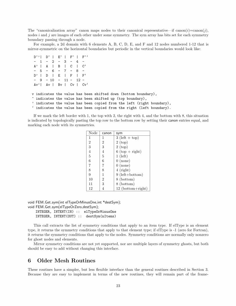
For example, a 2d domain with 6 elements A, B, C, D, E, and F and 12 nodes numbered 1-12 that ismirror-symmetric on the horizontal boundaries but periodic in the vertical boundaries would look like:
D^’| D^ | E^ | F^ | F^‘- 1 - 2 - 3 - 4 -A’ | A | B | C | C‘- 5 - 6 - 7 - 8 -D’ | D | E | F | F‘- 9 - 10 - 11 - 12 -Av’| Av | Bv | Cv | Cv‘
v indicates the value has been shifted down (bottom boundary),^ indicates the value has been shifted up (top boundary),’ indicates the value has been copied from the left (right boundary),‘ indicates the value has been copied from the right (left boundary).
If we mark the left border with 1, the top with 2, the right with 4, and the bottom with 8, this situationis indicated by topologically pasting the top row to the bottom row by setting their canon entries equal, andmarking each node with its symmetries.
Node canon sym1 1 3 (left + top)2 2 2 (top)3 3 2 (top)4 4 6 (top + right)5 5 1 (left)6 6 0 (none)7 7 0 (none)8 8 4 (right)9 1 9 (left+bottom)10 2 8 (bottom)11 3 8 (bottom)12 4 12 (bottom+right)
void FEM Get sym(int elTypeOrMinusOne,int *destSym);void FEM Get sym(elTypeOrZero,destSym);
INTEGER, INTENT(IN) :: elTypeOrMinusOneINTEGER, INTENT(OUT) :: destSym(nItems)
This call extracts the list of symmetry conditions that apply to an item type. If elType is an elementtype, it returns the symmetry conditions that apply to that element type; if elType is -1 (zero for Fortran),it returns the symmetry conditions that apply to the nodes. Symmetry conditions are normally only nonzerofor ghost nodes and elements.
Mirror symmetry conditions are not yet supported, nor are multiple layers of symmetry ghosts, but bothshould be easy to add without changing this interface.
6 Older Mesh Routines
These routines have a simpler, but less flexible interface than the general routines described in Section 3.Because they are easy to implement in terms of the new routines, they will remain part of the frame-
23

work indefinitely. These routines always use the default mesh, as returned by FEM Mesh default read andFEM Mesh default write.
void FEM Set elem(int elType,int nEl,int doublePerEl,int nodePerEl);void FEM Get elem(int elType,int *nEl,int *doublePerEl,int *nodePerEl);SUBROUTINE FEM Set elem(elType,nEl,doublePerEl,nodePerEl)
INTEGER, INTENT(IN) :: elType,nEl,doublePerEl,nodePerElSUBROUTINE FEM Get elem(elType,nEl,doublePerEl,nodePerEl)
INTEGER, INTENT(IN) :: elTypeINTEGER, INTENT(OUT) :: nEl,doublePerEl,nodePerEl
Describe/retreive the number and type of elements. ElType is a user-defined small, unique element typetag. nEl is the number of elements being registered. doublesPerEl and nodePerEl are the number of doublesof user data, and nodes (respectively) associated with each element.
doublePerEl or nodePerEl may be zero, indicating that no user data or connectivity data (respectively) isassociated with the element.
You can make this and any other mesh setup calls in any order—there is no need to make them inlinearly increasing order. However, for a given type of element FEM Set elem must be called before settingthat element’s connectivity or data.
void FEM Set elem conn(int elType,const int *conn);void FEM Get elem conn(int elType,int *conn);SUBROUTINE FEM Set elem conn r(elType,conn)
INTEGER, INTENT(IN) :: elTypeINTEGER, INTENT(IN), dimension(nodePerEl,nEl) :: conn
SUBROUTINE FEM Get elem conn r(elType,conn)INTEGER, INTENT(IN) :: elTypeINTEGER, INTENT(OUT), dimension(nodePerEl,nEl) :: conn
SUBROUTINE FEM Set elem conn c(elType,conn)INTEGER, INTENT(IN) :: elTypeINTEGER, INTENT(IN), dimension(nEl,nodePerEl) :: conn
SUBROUTINE FEM Get elem conn c(elType,conn)INTEGER, INTENT(IN) :: elTypeINTEGER, INTENT(OUT), dimension(nEl,nodePerEl) :: conn
Describe/retreive the element connectivity array for this element type. The connectivity array is indexedby the element number, and gives the indices of the nodes surrounding the element. It is hence nodePerEl*nElintegers long.
The C version array indices are zero-based, and must be stored in row-major order (a given element’ssurrounding nodes are stored contiguously in the conn array). The Fortran version indices are one-based,and are available in row-major (named r) and column-major (named c) versions. We recommend row-major storage because it results in better cache utilization (because the nodes around an element are storedcontiguously).
In this older interface, ghost nodes are indicated by invalid,
void FEM Set node(int nNode,int doublePerNode);void FEM Get node(int *nNode,int *doublePerNode);SUBROUTINE FEM Set node(nNode,doublePerNode)
INTEGER, INTENT(IN) :: nNode,doublePerNodeSUBROUTINE FEM Get node(nNode,doublePerNode)
INTEGER, INTENT(OUT) :: nNode,doublePerNode
Describe/retreive the number of nodes and doubles of user data associated with each node. There is only
24

one type of node, so no nodeType identifier is needed.doublePerNode may be zero, indicating that no user data is associated with each node.
6.1 Old Mesh Data
void FEM Set node data(const double *data);void FEM Get node data(double *data);void FEM Set elem data(int elType,const double *data);void FEM Get elem data(int elType,double *data);SUBROUTINE FEM Set node data r(data)
REAL*8, INTENT(IN), dimension(doublePerNode,nNode) :: dataSUBROUTINE FEM Get node data r(data)
REAL*8, INTENT(OUT), dimension(doublePerNode,nNode) :: dataSUBROUTINE FEM Set node data c(data)
REAL*8, INTENT(IN), dimension(nNode,doublePerNode) :: dataSUBROUTINE FEM Get node data c(data)
REAL*8, INTENT(OUT), dimension(nNode,doublePerNode) :: data
SUBROUTINE FEM Set elem data r(elType,data)INTEGER, INTENT(IN) :: elTypeREAL*8, INTENT(IN), dimension(doublePerElem,nElem) :: data
SUBROUTINE FEM Get elem data r(elType,data)INTEGER, INTENT(IN) :: elTypeREAL*8, INTENT(OUT), dimension(doublePerElem,nElem) :: data
SUBROUTINE FEM Set elem data c(elType,data)INTEGER, INTENT(IN) :: elTypeREAL*8, INTENT(IN), dimension(nElem,doublePerElem) :: data
SUBROUTINE FEM Get elem data c(elType,data)INTEGER, INTENT(IN) :: elTypeREAL*8, INTENT(OUT), dimension(nElem,doublePerElem) :: data
Describe/retrieve the optional, uninterpreted user data associated with each node and element. This userdata is partitioned and reassembled along with the connectivity matrix, and may include initial conditions,node locations, material types, or any other data needed or produced by the program. The Fortran arrayscan be row- or column- major (see FEM Set elem conn for details). The row-major form is preferred.
6.2 Old Ghost Numbering
In this older version of the framework, FEM Get node and FEM Get elem return the total number of nodesand elements, including ghosts. The routines below return the index of the first ghost node or element,where ghosts are numbered after all the real elements. This old ghost numbering scheme does not work wellwhen adding new ghosts, which is why the new ghost numbering scheme describes in Section 5.1 is used inthe new API.
int FEM Get node ghost(void);int FEM Get elem ghost(int elemType);
The examples below iterate over the real and ghost elements using the old numbering:
C version:int firstGhost,max;FEM Get node(&max, &ignored);firstGhost=FEM Get node ghost();
25

Figure 9: Old ghost element and node numbering. FEM Get ghost * returns g, FEM Get * returns n.
for (i=0;i<firstGhost;i++)... i is a real node...
for (i=firstGhost;i<max;i++)... i is a ghost node ...
Fortran version:call FEM Get node(max,ignored);firstGhost=FEM Get node ghost();do i=1,firstGhost-1
... i is a real node...end dodo i=firstGhost,max
... i is a ghost node...end do
6.3 Old Backward Compatability
void FEM Set mesh(int nElem, int nNodes, int nodePerEl,const int* conn);
This is a convenience routine equivalent to:
FEM Set node(nNodes,0);FEM Set elem(0,nElem,0,nodePerEl);FEM Set elem Conn(0,conn);
SUBROUTINE FEM Set mesh(nElem,nNodes,nodePerEl,conn)INTEGER, INTENT(IN) :: nElem, nNodes, nodePerElINTEGER, INTENT(IN), dimension(nElem,nodePerEl) :: conn;
This is a convenience routine equivalent to:
CALL FEM Set node(nNodes,0)CALL FEM Set elem(1,nElem,0,nodePerEl)CALL FEM Set elem Conn c(1,conn)
6.4 Old Sparse Data
Sparse data is typically used to represent boundary conditions. For example, in a structural dynamicsprogram typically some nodes have an imposed force or position. The routines in this section are used todescribe this kind of mesh-associated data—data that only applies to some “sparse” subset of the nodes orelements.
26

void FEM Set sparse(int S id,int nRec, const int *nodes,int nodesPerRec, const void *data,int dataPerRec,intdataType);SUBROUTINE FEM Set sparse(S id,nRec,nodes,nodesPerRec,data,dataPerRec,dataType)
INTEGER, INTENT(IN) :: S id,nRec,nodesPerRec,dataPerRec,dataTypeINTEGER, INTENT(IN) :: nodes(nodesPerRec,nRec)varies, INTENT(IN) :: data(dataPerRec,nRec)
Register nRec sparse data records with the framework under the number S id. The first call to FEM Set sparsemust give a S id of zero in C (1 in fortran); and subsequent calls to FEM Set sparse must give increasingconsecutive S ids.
One sparse data record consists of some number of nodes, listed in the nodes array, and some amountof user data, listed in the data array. Sparse data records are copied into the chunks that contains all thatrecord’s listed nodes. Sparse data records are normally used to describe mesh boundary conditions– for node-associated boundary conditions, nodesPerRec is 1; for triangle-associated boundary conditions, nodesPerRecis 3.
In general, nodePerRec gives the number of nodes associated with each sparse data record, and nodesgives the actual node numbers. dataPerRec gives the number of data items associated with each sparse datarecord, and dataType, one of FEM BYTE, FEM INT, FEM REAL, or FEM DOUBLE, gives the type of eachdata item. As usual, you may change or delete the nodes and data arrays after this call returns.
For example, if the first set of sparse data is 17 sparse data records, each containing 2 nodes stored inbNodes and 3 integers stored in bDesc, we would make the call:
/*C version*/FEM Set sparse(0,17, bNodes,2, bDesc,3,FEM INT);
! Fortran versionCALL FEM Set sparse(1,17, bNodes,2, bDesc,3,FEM INT)
void FEM Set sparse elem(int S id,const int *rec2elem);SUBROUTINE FEM Set sparse elem(S id,rec2elem)
INTEGER, INTENT(IN) :: S idINTEGER, INTENT(IN) :: rec2elem(2,nRec)
Attach the previously-set sparse records S id to the given elements. rec2elem consists of pairs of integers—one for each sparse data record. The first integer in the pair is the element type to attach the sparse recordto, and the second integer gives the element number within that type. For example, to attach the 3 sparserecords at S id to the elements numbered 10, 11, and 12 of the element type elType, use:
/*C version*/int rec2elem[]=elType,10, elType,11, elType,12;FEM Set sparse elem(S id,rec2elem);
! Fortran versioninteger :: rec2elem(2,3);rec2elem(1,:)=elTyperec2elem(2,1)=10; rec2elem(2,2)=11; rec2elem(2,3)=12;CALL FEM Set sparse elem(S id,rec2elem)
int FEM Get sparse length(int S id);void FEM Get sparse(int S id,int *nodes,void *data);function FEM Get sparse length(S id);
INTEGER, INTENT(IN) :: S idINTEGER, INTENT(OUT) :: FEM Get sparse Length
SUBROUTINE FEM Get sparse(S id,nodes,data);
27

INTEGER, INTENT(IN) :: S idINTEGER, INTENT(OUT) :: nodes(nodesPerRec,FEM Get sparse Length(S id))varies, INTENT(OUT) :: data(dataPerRec,FEM Get sparse Length(S id))
Retrieve the previously registered sparse data from the framework. FEM Get sparse length returns thenumber of records of sparse data registered under the given S id; zero indicates no records are available.FEM Get sparse returns you the actual nodes (translated to local node numbers) and unchanged user datafor these sparse records.
In this old interface, there is no way to access sparse ghosts.
28

7 Mesh Modification
void FEM Update mesh(FEM Update mesh fn routine, int callMeshUpdated,int doWhat);SUBROUTINE FEM Update mesh(routine,callMeshUpdated,doWhat)
external, INTENT(IN) :: routineINTEGER, INTENT(IN) :: callMeshUpdated,doWhat
Reassemble the mesh chunks from each partition into a single serial mesh, and call the given routine onthe assembled mesh. In this routine, which runs on processor 0, the FEM Get and FEM Set routines canmanipulate the serial mesh. The parameter callMeshUpdated, which must be non-zero, is passed down toroutine as routine(callMeshUpdated).
FEM Get calls from driver() will only return the new mesh after a FEM Update mesh call where doWhatis FEM MESH UPDATE; otherwise FEM Get from driver() will still return the old mesh. FEM Update meshcan only be called from driver; and must be called by the driver routine for every chunk.
doWhat Numeric Repartition? FEM Update meshFEM MESH OUTPUT 0 No driver() continues alongside routineFEM MESH FINALIZE 2 No driver() blocks until routine finishesFEM MESH UPDATE 1 Yes driver() blocks for the new partition
For example, FEM Update mesh(my output routine, k, FEM MESH OUTPUT) reassembles the mesh andcalls a routine named my output routine(k) while the driver routines continue with the computation. Thismight be useful, for example, for writing out intermediate solutions as a single file; writing outputs fromdriver() is more efficient but often results in a separate file for each mesh chunk.
To block the driver routines during a call to a routine named my finalize routine(k), such as at the endof the computation when the drivers have no other work to do, use FEM Update mesh(my finalize routine,k, FEM MESH FINALIZE).
To reassemble, modify, and repartition the mesh, use FEM Update mesh(my update routine, k, FEM MESH UPDATE).It may be easier to perform major mesh modifications from my update routine(k) than the drivers, sincethe entire serial mesh is available to my update routine(k).
FEM Update mesh reassembles the serial mesh with an attempt to preserve the element and node globalnumbering. If the new mesh has the same number and type of elements and nodes, the global numbers(and hence serial mesh) will be unchanged. If new elements or nodes are added at each chunk, they willbe assigned new unique global numbers. If elements or nodes are removed, their global numbers are notre-used– you can detect the resulting holes in the serial mesh since the user data associated with the deletedelements will be all zero. Generally, however, it is less error-prone to perform mesh modifications only indriver() or only in an update routine, rather than some in both.
8 IDXL Communication
The FEM framework’s communication layer is called IDXL. This small library handles sending and receivingdata to and from a sparse subset of 1D indices into a user array. The sparse index subset is called an ”IndexList”, hence the name of the library.
8.1 Index Lists
An Index List is the fundamental data structure of the IDXL library—for example, the list of shared nodesis an Index List. IDXL includes routines for building, combining, and sending and receiving Index Lists.
An Index List, as you might expect, is a list of indices that need to be sent and received. An Index Listincludes both the indices that need to be sent, as well as the indices to be received, from each chunk.
Consider two chunks a and b where b needs some information a has, such as if b has ghosts of real elementson a. a’s Index List thus has a send portion with the a-local indices for the elements a sends; and b’s Index
29

List contains a receive portion with the b-local indices for the elements b receives. Thus across processors,the corresponding send and receive portions of a and b’s Index Lists match, as shown in Figure 10.
Figure 10: Illustrating how Index Lists match up a’s source elements with b’s ghost elements.
8.1.1 Index List Calls
You refer to an Index List via an opaque handle—in C, the integer typedef IDXL t; in Fortran, a bareINTEGER.
IDXL t FEM Comm shared(int mesh,int entity);INTEGER function FEM Comm shared(mesh,entity)
INTEGER, INTENT(IN) :: mesh,entity
Return a read-only copy of the Index List of shared nodes. The send and receive portions of this list areidentical, because each shared node is both sent and received. Shared nodes are most often used with thesend/sum communication pattern.
Must be called from driver. mesh must be a reading mesh. entity must be FEM NODE. You may not callIDXL Destroy on the returned list.
IDXL t FEM Comm ghost(int mesh,int entity);INTEGER function FEM Comm ghost(mesh,entity)
INTEGER, INTENT(IN) :: mesh,entity
Return a read-only copy of the Index List of ghost entities. The send portion of this list contains real,interior entities, which are sent away; the receive portion of the list contains the ghost entites, which arereceived. Ghosts are most often used with the send/recv communication pattern.
Elements to be sent out are listed starting at zero (one in Fortran); but ghost elements to be received arealso listed starting at zero (one in Fortran). If real and ghost elements are kept in separate arrays, this isusable as-is; but if ghosts and real elements are kept together, you will need to shift the ghost indices usingIDXL Combine or IDXL Shift.
This routine must be called from driver. mesh must be a reading mesh. entity must not includeFEM GHOST–ghosts are already included. You may not call IDXL Destroy on the returned list.
30

IDXL t IDXL Create(void);INTEGER function IDXL Create()
Create a new, empty Index List. This list can then be filled up using IDXL Copy or IDXL Combine.Must be called from driver. You must eventually call IDXL Destroy on the returned list.
void IDXL Combine(IDXL t dest,IDXL t src,int startSend,int startRecv);SUBROUTINE IDXL Combine(dest,src,startSend,startRecv)
INTEGER, INTENT(IN) :: dest,src,startSend,startRecv
Add the shifted contents of the src Index List to dest. The send portion of src is shifted so the first indexsent will be startSend; for a ghost index list this is the index of the first sent real entity. The receive portionof src is similarly shifted so the first index received will be startRecv; for a ghost index list this is the indexof the first received ghost entity.
This routine does not check for duplicates—if an index originally appears in dest and the also in theshifted src, it will be listed twice.
8.1.2 Advanced Index List Calls
void IDXL Destroy(IDXL t l);SUBROUTINE IDXL Destroy(l)
INTEGER, INTENT(IN) :: l
Destroy this Index List, and free the list storage allocated by the framework. Only call this routine withlists you created using IDXL Create; not lists obtained directly from the FEM framework.
void IDXL Print(IDXL t l);SUBROUTINE IDXL Print(l)
INTEGER, INTENT(IN) :: l
Print out the contents of this Index List. This routine shows both the send and receive indices on thelist, for each chunk we communicate with.
void IDXL Copy(IDXL t dest,IDXL t src);SUBROUTINE IDXL Print(dest,src)
INTEGER, INTENT(IN) :: dest,src
Copy the contents of the source Index List into the destination Index List, which should be empty.
void IDXL Shift(IDXL t l,int startSend,int startRecv);SUBROUTINE IDXL Shift(l,startSend,startRecv)
INTEGER, INTENT(IN) :: l,startSend,startRecv
Like IDXL Combine, but only shifts the indices within a single list.
void IDXL Add entity(int newIdx,int nBetween,int *between);SUBROUTINE IDXL Add node(newIdx,nBetween,between)
INTEGER, INTENT(IN) :: newIdx,nBetweenINTEGER, INTENT(IN) :: between(nBetween)
31

This call adds a new entity, with local index newIdx, to this Index List. The new entity is sent or receivedby each chunk that sends or receives all the entites listed in the between array. For example, when addinga new node along an edge, nBetween is 2 and between lists the endpoints of the edge; this way if the edgeis shared with some chunk, the new node will be shared with that chunk.
This routine only affects the current chunk– no other chunks are affected. To ensure the communicationlists match, IDXL Add entity must be called on all the chunks that send or receive the entity, to create thelocal copies of the entity.
IDXL Add entity adds the new entity to the end of the communication list, and so must be called inthe same order on all the chunks that share the new entity. For example, if two new nodes x and y areadded between chunks a and b, if chunk a calls IDXL Add entity with its local number for x before it callsIDXL Add entity with its local number for y, chunk b must also add its copy of node x before adding y.
8.2 Data Layout
IDXL is designed to send and receive data directly out of your arrays, with no intermediate copying. Thismeans IDXL needs a completely general method for specifying how you store your data in your arrays.Since you probably don’t change your storage layout at runtime, you can create a “data layout” once at thebeginning of your program, then use it repeatedly for communication.
IDXL Layouts are normally used to describe arrays of data associated with nodes or elements. The layoutabstraction allows you to use IDXL routines to communicate any sort of data, stored in a variety of formats.
Like Index Lists, Layouts are referred to via an opaque handle—in a C program via the integer typedefIDXL Layout t, and in Fortran via a bare integer.
8.2.1 Layout Routines
In most programs, the data to be communicated is a dense array of data of one type. In this case, there isonly one layout routine you need to know:
IDXL Layout t IDXL Layout create(int type,int width);INTEGER function IDXL Layout create(type,width)
INTEGER, INTENT(IN) :: type,width
The simplest data layout to describe—a dense array of this IDXL datatype, indexed by entity number,with width pieces of data per entity. Note that the number of entities is not stored with the layout–thenumber of entities to be communicated depends on the communication routine.
The IDXL datatypes are:
IDXL Datatype C Datatypes Fortran DatatypesIDXL BYTE unsigned char INTEGER*1
char LOGICAL*1IDXL INT int INTEGERIDXL REAL float SINGLE PRECISION
REAL*4IDXL DOUBLE double DOUBLE PRECISION
REAL*8
For example, if you keep a dense array with 3 doubles of force per node, you’d call this routine as:
// C++ version:double *force=new double[3*n];IDXL Layout t force layout=IDXL Layout create(IDXL DOUBLE,3);
! F90 Versiondouble precision, allocatable :: force(:,:)integer :: force layout
32

ALLOCATE(force(3,n)) ! (could equivalently use force(3*n) )force layout=IDXL Layout create(IDXL DOUBLE,3)
This routine was once called FEM Create simple field.
8.2.2 Advanced Layout Routines
These advanced routines are only needed if you want to exchange data stored in an array of user-definedtypes. Most programs only need IDXL Layout create.
IDXL Layout t IDXL Layout offset(int type, int width, int offsetBytes, int distanceBytes,int skewBytes);INTEGER function IDXL Layout offset(type,width,offsetBytes,distanceBytes,skewBytes)
INTEGER, INTENT(IN) :: type,width,offsetBytes,distanceBytes,skewBytes
The most general data layout–an array indexed by entity, containing width pieces of data per entity.This routine expands on IDXL Layout create by adding support for user-defined types or other unusual datalayouts. You describe your layout by giving various in-memory byte offsets that describe the data is stored.Again, the number of entities is not stored with the layout–the number of entities to be communicateddepends on the communication routine.
• offsetBytes The number of bytes from the start of the array to the start of the data.
• distanceBytes The number of bytes taken by one entity.
• skewBytes The number of bytes between each piece of data. Since this can almost always be determinedfrom the size of the base data type, this parameter can be left as zero.
Figure 11: Describing a complex data layout.
For example, if your node data is all stored in a struct (in fortran, a named TYPE), offsetBytes givesthe distance between the start of the struct and the force; and distanceBytes gives the size in bytes of thestruct.
In C, the offsetof and sizeof keywords are useful for finding these values. In Fortran, we provide a specialroutine called foffsetof that returns the distance, in bytes, between its two arguments.
// C++ version:typedef struct {
double d[3], v[3], force[3], a[3];
33

double m;} node;node *nodes=new node[n];IDXL Layout t force layout=IDXL Layout offset(IDXL DOUBLE,3,
offsetof(node,force),sizeof(node),0);
! F90 VersionTYPE node
DOUBLE PRECISION :: d(3), v(3), force(3), a(3)DOUBLE PRECISION :: m
END TYPEinteger :: force layoutALLOCATE(nodes(n))force layout=IDXL Layout create(IDXL DOUBLE,3,
& foffsetof(nodes(1),nodes(1)%force),& foffsetof(nodes(1),nodes(2)),0)
void IDXL Layout destroy(IDXL Layout t layout);SUBROUTINE IDXL Layout destroy(layout)
INTEGER, INTENT(IN) :: layout
Destroy this Layout. You only need call this routine if you repeatedly create layouts.
int IDXL Get layout type(IDXL Layout t layout);INTEGER function IDXL Get layout type(layout)
Return the IDXL datatype for this layout.
int IDXL Get layout width(IDXL Layout t layout);INTEGER function IDXL Get layout width(layout)
Return the layout width—the number of data items that are communicated per entity.
int IDXL Get layout distance(IDXL Layout t layout);INTEGER function IDXL Get layout distance(layout)
Return the layout distance—the number of bytes between successive entity’s data items.
8.2.3 Layout Compatability Routines
Before IDXL was made a separate library, FEM included these routines, which are still preserved for backwardcompatability.
IDXL Layout t FEM Create simple field(int type,int width);INTEGER function FEM Create simple field(type,width)
INTEGER, INTENT(IN) :: type,width
This routine is completely interchangable to IDXL Layout create.
int FEM Create field(int type,int width,int offset,int distance);INTEGER function FEM Create field(type, width, offset, distance)
34

INTEGER, INTENT(IN) :: type, width, offset, distance
This routine is like a call to IDXL Layout offset with the rarely used skewBytes set to zero.
8.3 IDXL Communication
This section brings together all the pieces of IDXL: Index Lists are used to determine what to send and whatto receive and Layouts are used to determine where to get and put the communicated data.
8.3.1 Communication Routines
void IDXL Comm sendsum(IDXL Comm t comm,IDXL t indices,IDXL Layout t layout,void *data);SUBROUTINE IDXL Comm sendsum(comm,indices,layout,data)
INTEGER, INTENT(IN) :: comm,indices,layoutvaries, INTENT(INOUT) :: data
Sum these indices of shared entites across all chunks that share them. The user data array is interpretedaccording to the given layout.
If comm is zero, this routine is blocking and finishes the communication immediately. If comm is not zero,this routine is non-blocking and equivalent to a call to IDXL Comm send followed by a call to IDXL Comm sum.
This routine is typically used to sum up partial values on shared nodes. It is a more general version ofthe old FEM routine FEM Update field. For example, to sum up the shared-node values in a 3d force vectorindexed by node, you would use:
// C++ version:double *force=new double[3*nNodes];IDXL Layout t force layout=IDXL Layout create(IDXL DOUBLE,3);IDXL t shared indices=FEM_Comm_shared(mesh,FEM_NODE);
... in the time loop ...IDXL_Comm_sendsum(0,shared_indices,force_layout,force);
! F90 Versiondouble precision, allocatable :: force(:,:)integer :: force layout, shared_indicesALLOCATE(force(3,nNodes)) ! (could equivalently use force(3*nNodes) )force layout=IDXL Layout create(IDXL DOUBLE,3)shared_indices=FEM_Comm_shared(mesh,FEM_NODE)
... in the time loop ...CALL IDXL_Comm_sendsum(0,shared_indices,force_layout,force)
void IDXL Comm sendrecv(IDXL Comm t comm,IDXL t indices,IDXL Layout t layout,void *data);SUBROUTINE IDXL Comm sendrecv(comm,indices,layout,data)
INTEGER, INTENT(IN) :: comm,indices,layoutvaries, INTENT(INOUT) :: data
Send these (typically real) send indices and copy in these (typically ghost) receive indices. The user dataarray is interpreted according to the given layout.
If comm is zero, this routine is blocking and finishes the communication immediately. If comm is not zero,this routine is non-blocking and equivalent to a call to IDXL Comm send followed by a call to IDXL Comm sum.
35

This routine is typically used to obtain the values of ghost entities. It is a more general version of the oldFEM routine FEM Update ghost field. For example, to obtain 7 solution values per ghost element, storinggElem ghosts in the array just after the nElem regular elements, we could:
// C++ version:double *elem=new double[7*(nElem+gElem)];IDXL Layout t elem layout=IDXL Layout create(IDXL DOUBLE,7);IDXL t ghost original=FEM_Comm_ghost(mesh,FEM_ELEM+1);IDXL t ghost shifted=IDXL_Create(); // ghosts start at nElemIDXL_Combine(ghost_shifted,ghost_original,0,nElem);
... in the time loop ...IDXL_Comm_sendrecv(0,ghost_shifted,elem_layout,elem);
! F90 Versiondouble precision, allocatable :: elem(:,:)integer :: elem layout, ghost_original,ghost_shiftedALLOCATE(elem(7,nElem+gElem))elem layout=IDXL Layout create(IDXL DOUBLE,7)ghost original=FEM_Comm_ghost(mesh,FEM_ELEM+1)ghost shifted=IDXL_Create() ! ghosts start at nElem+1CALL IDXL_Combine(ghost_shifted,ghost_original,1,nElem+1)
... in the time loop ...CALL IDXL_Comm_sendrecv(0,ghost_shifted,elem_layout,elem)
8.3.2 Advanced Communication Routines
IDXL Comm t IDXL Comm begin(int tag,int context);INTEGER function IDXL Comm begin(tag,context)
INTEGER, INTENT(IN) :: tag,context
Start a non-blocking communication operation with this (user-defined) tag and communication context(0, or an AMPI communicator).
Every call to this routine must eventually be matched by a call to IDXL Comm wait. Warning: for now,tag and context are ignored, and there can be only one outstanding communication operation.
void IDXL Comm send(IDXL Comm t comm,IDXL t indices,IDXL Layout t layout,const void *data);SUBROUTINE IDXL Comm send(comm,indices,layout,data)
INTEGER, INTENT(IN) :: comm,indices,layoutvaries, INTENT(IN) :: data
When comm is flushed, send these send indices, with this layout, from this data array.This routine is always non-blocking; as the data array passed in will not be copied out until the call to
IDXL Comm flush.
void IDXL Comm recv(IDXL Comm t comm,IDXL t indices,IDXL Layout t layout,void *data);SUBROUTINE IDXL Comm recv(comm,indices,layout,data)
INTEGER, INTENT(IN) :: comm,indices,layoutvaries, INTENT(OUT) :: data
36

When comm is finished, copy in these receive indices, with this layout, into this data array.This routine is always non-blocking; as the data array passed in will not be copied into until the call to
IDXL Comm wait.
void IDXL Comm sum(IDXL Comm t comm,IDXL t indices,IDXL Layout t layout,void *data);SUBROUTINE IDXL Comm sum(comm,indices,layout,data)
INTEGER, INTENT(IN) :: comm,indices,layoutvaries, INTENT(INOUT) :: data
When comm is finished, add in the values for these receive indices, with this layout, into this data array.This routine is always non-blocking; as the data array passed in will not be added to until the call to
IDXL Comm wait.
void IDXL Comm flush(IDXL Comm t comm);SUBROUTINE IDXL Comm flush(comm)
INTEGER, INTENT(IN) :: comm
Send all outgoing data listed on this comm. This routine exists because there may be many calls toIDXL Comm send, and sending one large message is more efficient than sending many small messages.
This routine is typically non-blocking, and may only be issued at most once per IDXL Comm begin.
void IDXL Comm wait(IDXL Comm t comm);SUBROUTINE IDXL Comm wait(comm)
INTEGER, INTENT(IN) :: comm
Finish this communication operation. This call must be issued exactly once per IDXL Comm begin. Thiscall inclues IDXL Comm flush if it has not yet been called.
This routine always blocks until all incoming data is received, and is the last call that can be made onthis comm.
9 Old Communication Routines
(This section is for backward compatability only. The IDXL routines are the new, more flexible way toperform communication.)
The FEM framework handles the updating of the values of shared nodes– that is, it combines sharednodes’ values across all processors. The basic mechanism to do this update is the “field”– numeric data itemsassociated with each node. We make no assumptions about the meaning of the node data, allow variousdata types, and allow a mix of communicated and non-communicated data associated with each node. Theframework uses IDXL layouts to find the data items associated with each node in memory.
Each field represents a (set of) data records stored in a contiguous array, often indexed by node number.You create a field once, with the IDXL layout routines or FEM Create field, then pass the resulting fieldID to FEM Update field (which does the shared node communication), FEM Reduce field (which applies areduction over node values), or one of the other routines described below.
void FEM Update field(int Fid,void *nodes);SUBROUTINE FEM Update field(Fid,nodes)
INTEGER, INTENT(IN) :: Fidvaries, INTENT(INOUT) :: nodes
Combine a field of all shared nodes with the other chunks. Sums the value of the given field across allchunks that share each node. For the example above, once each chunk has computed the net force on eachlocal node, this routine will sum the net force across all shared nodes.
37

FEM Update field can only be called from driver, and to be useful, must be called from every chunk’sdriver routine.
After this routine returns, the given field of each shared node will be the same across all processors thatshare the node.
This routine is eqivalent to an IDXL Comm Sendsum operation.
void FEM Read field(int Fid,void *nodes,char *fName);SUBROUTINE FEM Read field(Fid,nodes,fName)
INTEGER, INTENT(IN) :: Fidvaries, INTENT(OUT) :: nodesCHARACTER*, INTENT(IN) :: fName
Read a field out of the given serial input file. The serial input file is line-oriented ASCII– each line beginswith the global node number (which must match the line order in the file), followed by the data to be readinto the node field. The remainder of each line is unread. If called from Fortran, the first line must benumbered 1; if called from C, the first line must be numbered zero. All fields are separated by white space(any number of tabs or spaces).
For example, if we have called Create field to describe 3 doubles, the input file could begin with
1 0.2 0.7 -0.3 First node2 0.4 1.12 -17.26 another node...
FEM Read field must be called from driver at any time, independent of other chunks.This routine has no IDXL equivalent.
void FEM Reduce field(int Fid,const void *nodes,void *out,int op);SUBROUTINE FEM Reduce field(Fid,nodes,outVal,op)
INTEGER, INTENT(IN) :: Fid,opvaries, INTENT(IN) :: nodesvaries, INTENT(OUT) :: outVal
Combine one record per node of this field, according to op, across all chunks. Shared nodes are notdouble-counted– only one copy will contribute to the reduction. After Reduce field returns, all chunks willhave identical values in outVal, which must be vec len copies of base type.
May only be called from driver, and to complete, must be called from every chunk’s driver routine.op must be one of:
• FEM SUM– each element of outVal will be the sum of the corresponding fields of all nodes
• FEM MIN– each element of outVal will be the smallest value among the corresponding field of all nodes
• FEM MAX– each element of outVal will be the largest value among the corresponding field of all nodes
This routine has no IDXL equivalent.
void FEM Reduce(int Fid,const void *inVal,void *outVal,int op);SUBROUTINE FEM Reduce(Fid,inVal,outVal,op)
INTEGER, INTENT(IN) :: Fid,opvaries, INTENT(IN) :: inValvaries, INTENT(OUT) :: outVal
Combine one record of this field from each chunk, acoording to op, across all chunks. Fid is only used forthe base type and vec len– offset and dist are not used. After this call returns, all chunks will have identicalvalues in outVal. Op has the same values and meaning as FEM Reduce field.
May only be called from driver, and to complete, must be called from every chunk’s driver routine.
38
! C exampledouble inArr[3], outArr[3];int fid=IDXL_Layout_create(FEM_DOUBLE,3);FEM_Reduce(fid,inArr,outArr,FEM_SUM);
! f90 exampleDOUBLE PRECISION :: inArr(3), outArr(3)INTEGER fidfid=IDXL_Layout_create(FEM_DOUBLE,3)CALL FEM_Reduce(fid,inArr,outArr,FEM_SUM)
This routine has no IDXL equivalent.
9.1 Ghost Communication
It is possible to get values for a chunk’s ghost nodes and elements from the neighbors. To do this, use:
void FEM Update ghost field(int Fid, int elTypeOrMinusOne, void *data);SUBROUTINE FEM Update ghost field(Fid,elTypeOrZero,data)
INTEGER, INTENT(IN) :: Fid,elTypeOrZerovaries, INTENT(INOUT) :: data
This has the same requirements and call sequence as FEM Update field, except it applies to ghosts. Youspecify which type of element to exchange using the elType parameter. Specify -1 (C version) or 0 (fortranversion) to exchange node values.
9.2 Ghost List Exchange
It is possible to exchange sparse lists of ghost elements between FEM chunks.
void FEM Exchange ghost lists(int elemType,int nIdx,const int *localIdx);SUBROUTINE FEM Exchange ghost lists(elemType,nIdx,localIdx)
INTEGER, INTENT(IN) :: elemType,nIdxINTEGER, INTENT(IN) :: localIdx[nIdx]
This routine sends the local element indices in localIdx to those neighboring chunks that connect to itsghost elements on the other side. That is, if the element localIdx[i] has a ghost on some chunk c, localIdx[i]will be sent to and show up in the ghost list of chunk c.
int FEM Get ghost list length(void);Returns the number of entries in my ghost list—the number of my ghosts that other chunks passed to theircall to FEM Exchange ghost lists.
void FEM Get ghost list(int *retLocalIdx);SUBROUTINE FEM Get ghost list(retLocalIdx)
INTEGER, INTENT(OUT) :: retLocalIdx[FEM Get ghost list length()]
These routines access the list of local elements sent by other chunks. The returned indices will all referto ghost elements in my chunk.
39

10 ParFUM
ParFUM is the name for the latest version of FEM. ParFUM includes additional features including parallelmesh modification and adaptivity (geometrical). ParFUM also contains functions which generate additionaltopological adjacency information. ParFUM cannot be built separate from Charm++ since it uses variousmessaging mechanisms that MPI does not readily support. It is important to note that ParFUM adaptivityat the moment has some limitations. It works only for meshes which are two-dimensional. The otherlimitation is that the mesh on which it works on must have one layer of node-deep ghosts. Most applicationsreqire no or one layer ghosts, so it is really not a limitation, but for applications that need multiple layers ofghost information, the adaptivity operations cannot be used.
10.1 Adaptivity Initialization
If a FEM application wants to use parallel mesh adaptivity, the first task is to call the initialization routinefrom the driver function. This creates the node and element adjacency information that is essential for theadaptivity operations. It also initializes all the mesh adaptivity related internal objects in the framework.void FEM ADAPT Init(int meshID)
Initializes the mesh defined by meshID for the mesh adaptivity operations.
10.2 Preparing the Mesh for Adaptivity
For every element entity in the mesh, there is a desired size entry for each element. This entry is calledmeshSizing. This meshSizing entry contains a metric that decides the element quality. The default metricis the average of the size of the three edges of an element. This section provides various mechanisms to setthis field. Some of the adaptive operations actually use these metrics to maintain quality. Though there isanother metric which is computer for each element and maintained on the fly and that is the ratio of thelargest length to the smallest altitude and this value during mesh adaptivity is not allowed to go beyond acertain limit. Because the larger this value after a cecrtain limit, the worse the element quality.void FEM ADAPT SetElementSizeField(int meshID, int elem, double size);
For the mesh specified by meshID, for the element elem, we set the desired size for each element to besize.void FEM ADAPT SetElementSizeField(int meshID, double *sizes);
For the mesh specified by meshID, for the element elem, we set the desired size for each element fromthe corresonponding entry in the sizes array.void FEM ADAPT SetReferenceMesh(int meshID);
For each element int this mesh defined by meshID set its size to the average edge length of the corre-sponding element.void FEM ADAPT GradateMesh(int meshID, double smoothness);
Resize mesh elements to avoid jumps in element size. i.e. avoid discontinuities in the desired sizes forelements of a mesh by smoothing them out. Algorithm based on h-shock correction, described in MeshGradation Control, Borouchaki et al.
10.3 Modifying the Mesh
Once the elements in the mesh has been prepared by specifying there desired sizes, we are ready to usethe actual adaptivity operations. Currently we provide delauney flip operations, edge bisect operations andedge-coarsen operations all of which are implemented in parallel, but the user has access to these wrapperfunctions which interlligently decide when and in which region of the mesh to use the adaptivity operationsto generate a mesh with higher quality elements while achieving the desired size (which is usually averageedge length per element), or it could even be the area of each element.void FEM ADAPT Refine(int meshID, int qm, int method, double factor,double *sizes);
Perform refinements on the mesh specified by meshId. Tries to maintain/improve element quality byrefining the mesh as specified by a quality measure qm. If method = 0, refine areas with size larger than
40

factor down to factor If method = 1, refine elements down to sizes specified in the sizes array. In this arrayeach entry corresponds to the corresponding element. Negative entries in sizes array indicate no refinement.void FEM ADAPT Coarsen(int meshID, int qm, int method, double factor,double *sizes);
Perform refinements on the mesh specified by meshId. Tries to maintain/improve element quality bycoarsening the mesh as specified by a quality measure qm. If method = 0, coarsen areas with size smallerthan factor down to factor If method = 1, coarsen elements up to sizes specified in the sizes array. Inthis array each entry corresponds to the corresponding element. Negative entries in sizes array indicate nocoarsening.void FEM ADAPT AdaptMesh(int meshID, int qm, int method, double factor,double *sizes);
It has the same set of arguments as required by the previous two operations, namely refine and coarsen.This function keeps using the above two functions till we have all elements in the mesh with as close to thedesired quality. Apart from using the above two operations, it also performs a mesh repair operation whereit gets rid of some bad quality elements by delauney flip or coarsening as the geometry in the area demands.int FEM ADAPT SimpleRefineMesh(int meshID, double targetA, double xmin, double ymin, double xmax, doubleymax);
A region is defined by (xmax, xmin, ymax, ymin) and the target area to be achieved for all elementsin this region in the mesh specified by meshID is given by targetA. This function only performs a series ofrefinements on the elements in this region. If the area is larger, then no coarsening is done.int FEM ADAPT SimpleCoarsenMesh(int meshID, double targetA, double xmin, double ymin, double xmax, dou-ble ymax);
A region is defined by (xmax, xmin, ymax, ymin) and the target area to be achieved for all elementsin this region in the mesh specified by meshID is given by targetA. This function only performs a series ofcoarsenings on the elements in this region. If the area is smaller, then no refinement is done.
10.4 Verifiy correctness of the Mesh
After adaptivity operations are performed and even before adaptivity operations, it is important to first verifythat we are working on a mesh that is consistent geometrically with the types of mesh that the adaptivityalgorithms are designed to work on. There is a function that can be used to test various properties of amesh, like area, quality, geometric consistency, idxl list correctness, etc.void FEM ADAPT TestMesh(int meshID);
This provides a series of tests to determine the consistency of the mesh specified by meshID.These four simple steps define what needs to be used by a program that wishes to use the adaptivity
features of ParFUM.
10.5 ParFUM developers
This manual is meant for ParFUM users, so developers should look at the source code and the doxygengenerated documentaion.
41