Embed Size (px)
Citation preview

13 Charles H. Sain G. William QuinbyConsulting Engineer
Birmingham, AlabamaConsulting Engineer
Golden, Colorado
EARTHWORK
Earthwork involvesmovement of aportionof the earth’s surface from one locationto another and, in its new position,creation of a desired shape and physical
condition. Occasionally, the material moved isdisposed of as spoil. Because of the wide vari-ety of soils encountered and jobs to be doneon them, much equipment and many methodshave been developed for the purpose. Thissection describes and analyzes the equipment andmethods.
13.1 Types of Excavation
A common method of classifying excavation is bytype of excavated material: topsoil, earth, rock,muck, and unclassified.
Topsoil excavation is removal of the exposedlayer of the earth’s surface, including vegetation.Since the topsoil, or mantle soil, supports growth oftrees and other vegetation, this layer contains moremoisture than that underneath. So that the lowerlayer will lose moisture and become easier tohandle, it is advantageous to remove the topsoil assoon as possible. When removed, topsoil usually isstockpiled. Later, it is restored on the site forlandscaping or to support growth of vegetation tocontrol erosion.
Earth excavation is removal of the layer of soilimmediately under the topsoil and on top of rock.Used to construct embankments and foundations,earth usually is easy to move with scrapers or othertypes of earthmoving equipment.
Rock excavation is removal of a formation thatcannot be excavated without drilling and blasting.Any boulder larger than 1⁄2 yd
3 generally is classi-fied as rock. In contrast, earth is a formation that
when plowed and ripped breaks down into smallenough pieces to be easily moved, loaded inhauling units, and readily incorporated into anembankment or foundation in relatively thinlayers. Rock, when deposited in an embankment,is placed in thick layers, usually exceeding 18 in.
Muck excavation is removal of material thatcontains an excessive amount of water and un-desirable soil. Its consistency is determined by thepercentage of water contained. Because of lack ofstability under load,muck seldom can be used in anembankment. Removal of water can be accom-plished by spreading muck over a large area andletting it dry, by changing soil characteristics, or bystabilizing muck with some other material, therebyreducing the water content.
Unclassified excavation is removal of anycombination of topsoil, earth, rock, and muck.Contracting agencies frequently use this classifi-cation. It means that earthmoving must be donewithout regard to the materials encountered. Muchexcavation is performed on an unclassified basisbecause of the difficulty of distinguishing, legallyor practically, between earth, muck, and rock.Unclassified excavation must be carried out tothe lines and grades shown on the plans with-out regard to percentage of moisture and typeof material found between the surface and finaldepth.
Excavation also may be classified in accordancewith the purpose of the work, such as stripping,roadway, drainage, bridge, channel, footing, bor-row. In this case, contracting agencies indicate thenature of the excavation for which materials are tobe removed. Excavation designations differ withagencies and locality. Often, the only reason acertain type of excavation has a particular desig-nation is local custom.
Downloaded from Digital Engineering Library @ McGraw-Hill (www.digitalengineeringlibrary.com)Copyright © 2004 The McGraw-Hill Companies. All rights reserved.
Any use is subject to the Terms of Use as given at the website.
Source: Standard Handbook for Civil Engineers

Stripping usually includes removal of allmaterial between the original surface and the topof any material that is acceptable for permanentembankment.
Roadway excavation is that portion of a high-way cut that begins where stripping was com-pleted and terminates at the line of finishedsubgrade or bottom of base course. Often, however,stripping is made part of roadway excavation.
Drainage excavation or structure excavation isremoval of material encountered during installa-tion of drainage structures other than bridges.Those structures are sometimes referred to asminor drainage structures and include roadwaypipe and culverts. A culvert is usually defined asany structure under a roadway with a clear spanless than 20 ft, whereas a bridge is a structurespanning more than 20 ft. After a pipe or culverthas been installed, backfilling must be done withacceptable material. This material usually isobtained from some source other than drainageexcavation, which generally is not acceptable orworkable. Often, culvert excavation does notinclude material beyond a specified distance fromthe end of a culvert.
Bridge excavation is removal of materialencountered in digging for footing and abutments.Often, bridge excavation is subdivided into wet,dry, and rock excavation. The dividing linebetween wet and dry excavation usually is denotedby specification of a ground elevation, above whichmaterial is classified as dry and below which aswet. A different elevation may be specified for eachfoundation.
Channel excavation is relocation of a creek orstream, usually because it flows through a right-of-way. A contracting agency will pay for any inlet oroutlet ditch needed to route water through a pipeas channel excavation, to the line where culvertexcavation starts.
Footing excavation is the digging of a column orwall foundation for a building. This work usually isdone to as neat a line and grade as possible, so thatconcrete may be cast without forms. Althoughelimination of forms saves money, special equip-ment and more-than-normal handwork are usuallyrequired for this type of excavation.
Borrow excavation is the work done inobtaining material for embankments or fills froma source other than required excavation. In mostinstances, obtaining material behind slope lines isclassified as borrow, although it commonly is
considered as getting material from a source off thesite. Most specifications prohibit borrow until allrequired excavation has been completed or theneed for borrow has been established beyond areasonable doubt. In some cases, need for amaterial not available in required excavationmakes borrow necessary. A borrow pit usually hasto be cleared of timber and debris and thenstripped of topsoil before desired material can beexcavated.
Dredge excavation is the removal of materialfrom under water.
13.2 Basic ExcavatingEquipment
A tractor is the most widely used excavating tool.Essentially, it is a power source on wheels or tracks(crawler). Equipped on the front with a bulldozer, asteel blade that can be raised and lowered, a tractorcan push earth from place to place and shape theground. If a scraper is hooked to the drawbar andmeans of raising, lowering, and dumping areprovided, a tractor-drawn scraper results. Additionof other attachments creates tools suitable fordifferent applications (see also Art. 13.7).
Another basic machine is one that by attach-ment of different fronts may be converted into ashovel, dragline, clamshell, backhoe, crane, or piledriver. The basic machine made for a shovel,however, has shorter and narrower tracks than onemade for a dragline or clamshell, and morecounterweight has to be added to the back. Ashovel attachment will fit the basic machine madefor a dragline or clamshell, but the longer trackswill interfere with the shovel (see also Art. 13.4).
Scrapers may be tractor-drawn or self-propel-led. More excavation is moved with self-propelledor rubber-tired scrapers than with scrapers towedand controlled by crawler tractors (see also Art.13.8).
Trenchers, used for opening trenches andditches, may be ladder or wheel type. They domost of the pipeline excavation in earth. Theladder type has chains to which are attachedbuckets that scoop up earth as the chains move. Itis adaptable to deep excavation. The wheel typehas digging buckets on the circumference of arotating wheel. The buckets dump excavatedmaterial into a conveyor mounted in the centerof the wheel. This type of trencher is used mainly
13.2 n Section Thirteen
Downloaded from Digital Engineering Library @ McGraw-Hill (www.digitalengineeringlibrary.com)Copyright © 2004 The McGraw-Hill Companies. All rights reserved.
Any use is subject to the Terms of Use as given at the website.
EARTHWORK

for shallow trenches. Neither type is used to anygreat extent when rock is encountered in trenchexcavation.
Wheel excavators, used in constructing earthdams or in strip mining, excavate soft or granularmaterials at very high rates. For example, oneexcavator with a 28-ft wheel moves 1500 tons ofiron ore per hour. A typical wheel excavator re-sembles a wheel-type trencher. Buckets mountedon a wheel 12 or more ft in diameter scoop up theearth. They may be 2 ft or more wide, with acapacity of 1⁄3 yd
3 or more, and equipped with astraight cutting edge or teeth. The buckets dumpinto a hopper, which feeds the earth onto aconveyor belt. The belt moves along a boom,which may be 200 ft or more long, to dump theearth into another hopper. This hopper in turnfeeds the earth to a stockpile or to earthmovingequipment.
13.3 Selecting BasicEquipment
Type of material to be excavated may determinethe basic equipment to be used. But length andtype of haul road must also be considered. Forexample, suppose excavation is in earth and bestresults could be obtained with rubber-tiredscrapers, but the haul is over city streets. In thiscase, this type of equipment probably could not beused because of heavy wheel loads and inter-ference with traffic.
For rock, a front-end loader, backhoe, or shovelwould be the basic rig. For earth, when a haul roadcan be built, scrapers would be chosen. But if theearth has to be moved several miles over existingstreets or highways, the choice would be a front-end loader, shovel, or backhoe that would loaddump trucks. Whether a shovel or backhoe wouldbe used depends onwhether the excavation bottomcan support a front-end loader or shovel andhauling units. If the bottom is too soft, a dragline orbackhoe would be required. A dragline can sitoutside the excavation and load a hauling unitat the same level (loading on top). But when abackhoe can be used, it is preferred to a draglinebecause of greater production.
Therefore, in selecting basic equipment, con-sider:
Types of material to be excavated
Types and size of hauling equipment to be used
Load-supporting ability of original ground
Load-supporting ability of material to be excavated
Volume of excavation to be moved
Volume to be moved per unit of time
Length of haul
Type of haul road
13.4 General Equipment forExcavation andCompaction
Clearing or Grubbing
Use tractor with bulldozer or root rake.Bulldozer can fell trees, uproot stumps.Root rake piles for burning, makes cleaner pile.Brush hog may be required for light brush.
Grubbing
Use low-strength explosives, slow detonation speed.
Clearing
Drag chain or chain and heavy ball between twotractors. Useful for trees that break easily. Tractorsequipped with cutter blades can operate on anyfooting and cut any tree at ground level.
Stripping
Bulldozers are limited by length of push or haul butare useful for swampy conditions.
Scrapers are limited by terrain and supportability of ground; they may be tractor-drawn forshort hauls.
Draglines are limited by depth of stripping,ability to service with hauling units, and space forcasting the bucket. They are used where swampyconditions prevent other equipment from beingused.
Graders are limited to use where stripping can bewindrowed on final position. Material can beloaded from a windrow by a front-end loader.
Pipe Installation
Backhoes are used on firm soil where depth oftrench is not excessive; they are good in rock.
Earthwork n 13.3
Downloaded from Digital Engineering Library @ McGraw-Hill (www.digitalengineeringlibrary.com)Copyright © 2004 The McGraw-Hill Companies. All rights reserved.
Any use is subject to the Terms of Use as given at the website.
EARTHWORK

Draglines are used for deep trenches if the sidescan be flattened; they have difficulty digging ver-tical walls.
Clamshells are used where sheeting of sides isrequired and it is necessary to dig between bracesand to great depths. They are inefficient in rock.
Bulldozers are limited to shallow excavation.Trenching machines produce vertical or near-
vertical walls and can maintain line and earthgrade.
Earth Excavation
Tractor-drawn scrapers are limited by length of hauland supporting ability of the soil. Cost getsexcessive if haul distance greatly exceeds 1000 ft.
Two-axle, rubber-tired, self-propelled scrapers arelimited by length of haul, terrain, and supportingability of the soil; they bounce on long hauls at topspeed.
Three-axle, rubber-tired, self-propelled scrapers needmaneuvering or working space and are limited byterrain and supporting ability of soil. They aremostefficient on long hauls.
Twin-engine, rubber-tired scrapers have few limi-tations. They are useful in rough terrain and wheretraction is needed on all wheels.
Front-end loaders generally discharge into haul-ing units if the haul greatly exceeds 100 ft and theyalso are limited by digging and dumping ease ofexcavated material.
Shovels are also used to load into hauling units.Working room must be ample and distance to castshort. Shovels also have to dig from a face.
Draglinesmay be used where excavation is deepand the material has no supporting ability. Materialshould be easy to dig. Draglines usually load intohauling units.
Wheel excavators offer high excavation rate andloading into hauling units with soft or granularsoils.
Mobile belt loaders (Fig. 13.1) give high-produc-tion loading into hauling units but are limited byworking room and supporting capacity of exca-vation bottom. Belt loaders are limited to short,infrequent moves. A wide belt handles some rockexcavation.
Dredges usually are used where transportationand digging costs are prohibitive if other thanwater-borne equipment is used. Water must beavailable for mixing with the excavated materialfor pumping through pipes. Distance to spoil areashould not be too great.
Clamshells are low producers but are useful insmall or deep spaces, where there is no overheadinterference with swinging of the boom.
Gradall, not a high-production tool, is suitablefor dressing or finishing where tolerances are close.
Scoopers, hydraulically operated, are high-pro-duction equipment, limited by dumping heightand to easily dug material. Production is notso greatly influenced by height of face as for ashovel.
Rock Excavation
Shovels can dig any type of rock broken into piecesthat can be easily dug. Limited to digging from a
Fig. 13.1 Mobile belt loader. (Barber-Greene Co.)
13.4 n Section Thirteen
Downloaded from Digital Engineering Library @ McGraw-Hill (www.digitalengineeringlibrary.com)Copyright © 2004 The McGraw-Hill Companies. All rights reserved.
Any use is subject to the Terms of Use as given at the website.
EARTHWORK

face, shovels are used for high-production loadinginto hauling units.
Bulldozers are limited to short movements andeasily dug rock. Sometimes, they are used to dis-pose of boulders when drilling and blasting are noteconomical.
Front-end loaders are used instead of shovelsbecause of their high production, lower cost ofoperation, and ease of moving from job to job.
Backhoes are used for foundation excavation,trenches, and high production in rough terrain.They must dig below their tracks.
Scrapers are suitable for short movements androck broken down to small sizes, such as blastedshale, but tire wear may be greater than in otherapplications.
Scoopers may be used instead of shovels whereworking space is tight. They are limited by theheight of hauling units and to easily dug rock.
Gradalls are used for trench and foundationexcavation, but material must be well blasted.
Clamshells are most suitable for deep foun-dations or where the reach from machine positionto excavation prohibits other equipment frombeing used. Rock must be well broken for maxi-mum production.
Compaction
Sheepsfoot rollers, made with feet of various shapes,offer high-speed production. Compaction dependson unit pressure and speed of roller. They are notsuitable for compacting sand. They also are limitedby depth of layer to be compacted.
Rubber-tired rollers are used for granular soils,including shales and rock. Ranging from very lightweight to 200 tons, they may be self-propelledor towed. Depth of lift compacted depends onweight.
Vibratory compactors, towed, self-propelled, orhand-held, are also used for granular soils. Com-paction ability depends on frequency and energy ofvibrations. Depth of lift is not so much a factor asfor other types of compactors.
Grid rollers, useful in breaking down oversizeparticles, are limited to shallow lifts of nonstickymaterial. They can be towed at any safe, economicalspeed.
Air tamps are used to backfill pipe and foun-dationsand forwork inareasnot accessible topowerequipment. Usually hand-held, they are poweredby compressed air imparting reciprocating blows.
They are limited to low production and shallowlifts.
Paddlefoot rollers, usually self-propelled, com-pact from the top of lift down. They are limited toan average depth (up to 8 in) of lift in all soils.
A rubber-tired front-end loader can be converted tothis type of roller by a change of wheels.
Steel-wheel rollers, self-propelled, are used wherea smooth, sealed surface is desired. They arelimited to shallow depth of lift.
13.5 Power Shovels,Draglines, Clamshells,and Backhoes
These four machines are made by installing anattachment on a basic machine, which may bemounted on crawler tracks or a trucklike chassis(Art. 13.2). (See Figs. 13.2 to 13.5.) When mountedon a trucklike chassis, the machine usually isdesigned for use as a truck crane, but it also can beused as a shovel or backhoe if mobility is desiredand low production is acceptable. Most backhoes,however, are hydraulic and cannot be converted.
There is not much difference between equip-ment used as a clamshell and that used as adragline or crane. A boom used with a clamshellhas two-point sheaves, so that two cables can attachto the bucket. One cable is used to open and closethe bucket and the other to hoist or lift the bucket.Since the two cables should travel at the same
Fig. 13.2 Dragline.
Earthwork n 13.5
Downloaded from Digital Engineering Library @ McGraw-Hill (www.digitalengineeringlibrary.com)Copyright © 2004 The McGraw-Hill Companies. All rights reserved.
Any use is subject to the Terms of Use as given at the website.
EARTHWORK

speed, the drums on a clamshell are the same size.To keep the bucket from spinning and twisting thehoist and closing lines, a tagline extends betweenthe bucket and a spring-loaded reel on the side ofthe boom (Fig. 13.4).
A dragline has a hoist cable that goes through apoint sheave atop the boom and attaches to thebucket. Another line, the drag cable, goes throughthe fairlead and attaches to the bucket (Fig. 13.2).The drum that exerts pull on the drag cable issmaller than the hoist drum because more force isrequired on the drag cable than on the hoist lines.Typical performance factors for a dragline aregiven in Tables 13.1 and 13.6.
Power shovels are used primarily to load rockinto hauling units. Production depends on type ofmaterial to be loaded, overall job efficiency, angle
of swing, height of bank or face the shovel digsagainst, ability of operator, swell of material, slopeof ground machine is working on, and whetherhauling units are of optimum size and adequate innumber. For highest efficiency, the degree of swingshould be held to a minimum. (Typical perform-ance factors are given in Table 13.2.) Working theshovel so that a hauling unit can be loaded on eachside is desirable so there is no lost time waiting fora hauling unit to get into position.
Table 13.3 gives estimated hourly production ofpower shovels. It is based on bank cubic yardsmeasure, 908 swing, optimum digging depth,grade-level loading, 100% efficiency, 60-min hour,and bucket-fill factor of 1.00 (see Table 13.5).
Fig. 13.3 Hydraulic excavator (backhoe). (Cater-pillar Tractor Co.)
Fig. 13.4 Clamshell.
Fig. 13.5 Excavating and crane attachments.
Table13.1 TypicalDraglineCalculatingFactors:Average Swing Cycle with 1108 Swing
Bucket capacity, yd3 1⁄2 11⁄2 2Time, s 24 30 33
Bucket Factors
Type of digging% of rated capacity
(approx)
Easy 95–100Medium 80–90Medium hard 65–75Hard 40–65
13.6 n Section Thirteen
Downloaded from Digital Engineering Library @ McGraw-Hill (www.digitalengineeringlibrary.com)Copyright © 2004 The McGraw-Hill Companies. All rights reserved.
Any use is subject to the Terms of Use as given at the website.
EARTHWORK

Table 13.4 indicates the effect on production ofdepth of cut and angle of swing.
Optimum digging depth is the shortest distancea bucket must travel up a face or bank to obtain itsload. This depth usually is the vertical distancefrom shipper shaft (dipper-stick pivot shaft) toground level. Optimum depth varies with type ofmaterial to be excavated since a lower boom isneeded for hard materials than for soft.
Work must be planned to load or move themaximum yardage each shift: Locate the shoveland hauling units for the shortest swing of theshovel. If it is necessary to work high, dig the upperportion first. Move up to the face while a haulingunit is getting into position. Make short movesfrequently, instead of less frequent long moves.Stay close to the face; do not dig at the end of the
stick. Lower the dipper only enough to get a fullbucket; this cuts down on hoist time. Keep dipperteeth sharp. Have spare cables and dipper teethreadily available near the shovel. Hoist the load nomore than necessary to clear the hauling-unit bed.Start the swing when the bucket is full and clear ofthe bank. Spot the hauling unit under the boompoint so it is not necessary to crowd or retract todump into the bed (Fig. 13.6). Break rock well foreasier digging.
A dragline is more versatile than a shovel. Witha dragline, load can be obtained from a greaterdistance from the machine (reach is greater). Ex-cavation can be done below water and at a longdistance above or below the dragline. A largerbucket than the machine’s rated capacity can beused if a short boom is installed. It is not uncom-mon for a machine rated at 21⁄2 yd
3 to be loadingwith a 4-yd3 bucket into hauling units. But weightof bucket and load should not exceed 70% of thetipping load of the machine. (Lifting-crane capacityis based on 75% of actual tipping load. A draglinemay approach this if it is on solid footing and isdigging good-handling material.)
Since a dragline loads its bucket by pulling ittoward the machine, the pit or face slopes frombottom to top toward the dragline. Best produc-tion is obtained by removing material in nearlyhorizontal layers and working from side to side ofthe excavation. A keyway, or slot, should be cutnext to the slope. This keyway should always beslightly lower than the area being taken off inhorizontal layers. A good operator fills the bucket
Table 13.2 Typical Shovel Calculating Factors:Average Swing Cycle with 908 Swing
Bucket capacity, yd3 1⁄2 1 11⁄2 2 21⁄2Time, s 20 21 22 23 24
Dipper Factors
Type of digging% of rated capacity
(approx)
Easy 95–100Medium 85–90Medium hard 70–80Hard 50–70
Table 13.3 Estimated Hourly Production of Dipper-Type Power Shovel*
Material classShovel dipper sizes, yd3
1⁄23⁄4 1 11⁄4 11⁄2 2 21⁄2 3 4 41⁄2 5 6 7 8 9 10
Moist loam orsandy clay
115 165 205 250 285 355 405 454 580 635 685 795 895 990 1075 1160
Sand and gravel 110 155 200 230 270 330 390 450 555 600 645 740 835 925 1010 1100Common earth 95 135 175 210 240 300 350 405 510 560 605 685 765 845 935 1025Clay, tough hard 75 110 145 180 210 265 310 360 450 490 530 605 680 750 840 930Rock, well blasted 60 95 125 155 180 230 275 320 410 455 500 575 650 720 785 860Common with rock 50 80 105 130 155 200 245 290 380 420 460 540 615 685 750 820Clay, wet and sticky 40 70 95 120 145 185 230 270 345 385 420 490 555 620 680 750Rock, poorly blasted 25 50 75 95 115 160 195 235 305 340 375 440 505 570 630 695
* Caterpillar Tractor Co.
Earthwork n 13.7
Downloaded from Digital Engineering Library @ McGraw-Hill (www.digitalengineeringlibrary.com)Copyright © 2004 The McGraw-Hill Companies. All rights reserved.
Any use is subject to the Terms of Use as given at the website.
EARTHWORK

as soon as possible, within a distance less than thebucket length. Digging on a slight incline helps fillthe bucket. When the bucket is full, it should benearly under the boom point and should be liftedas drag ceases.
As with shovels, a relatively shallow pit yieldsthe greatest efficiency for draglines. The haulingunits should be in the excavation or at the sameelevation to which the dragline is digging. Thus,when the bucket is full, it will have a short lift toreach the top of the hauling units. If the pit bottomis soft or for some other reason hauling unitscannot be spotted below the machine, then loadingon top must be resorted to, with a loss in loadingefficiency. Table 13.6 indicates dragline productionin cubic yards bank measure per hour. The table isbased on suitable depth of cut for maximum effect,no delays, 908 swing, and all materials loaded intohauling units (see also Table 13.1).
Production of clamshells, like that of draglines,depends on radius of operation and lifting capacity.It is general practice to limit the clamshell load,including bucket weight, to 50% of the full power-line pull at the short boom radius.
Types of clamshell bucket are general-purpose,rehandling, and heavy excavating. The rehandlingbucket is best for unloading materials from bins orrailroad cars or loading materials from stockpiles.The heavy-excavation bucket is used for extremeservice, such as placing riprap. It can be adjusted sothat the operation is easy on components since aclamshell does not demand a tightly adjusted fric-tion band. The general-purpose bucket is betweenthe rehandling and excavating buckets and can beused with or without teeth.
13.6 Tractor Shovels
Also commonly known as front-end loaders, tractorshovels can be mounted on wheels (Fig. 13.7) orcrawler tracks (Fig. 13.8). A crawler is desirableif moving it from one job to another is no problem,haul distance is short, and type of excavationbottom is not suitable for rubber tires. Most wheelloaders have four-wheel drive.
Capacity of a tractor shovel depends on unitweight of material to be handled, so there is avariety of buckets for each loader. These are ofthree basic types: hydraulically controlled, gravitydump, and overhead (overshot). Hydraulicallycontrolled machines are preferable for most oper-ations. The overhead is desirable where workingroom for turning is unavailable.
All loaders except overhead use a load, turn,dump cycle. For best efficiency and reduction ofwear on tires or undercarriage, turning should beheld to a minimum.
A loader should dig from a relatively low heightof bank or face. Since most loaders are equippedwith automatic bucket positions, the height of bank
Table 13.4 Correction Factors for Effect of Depth of Cut and Angle of Swing on Power-Shovel Output*
Depth ofcut, % of
Angle of swing, deg
optimum 45 60 75 90 120 150 180
40 0.93 0.89 0.85 0.80 0.72 0.65 0.5960 1.10 1.03 0.96 0.91 0.81 0.73 0.6680 1.22 1.12 1.04 0.98 0.86 0.77 0.69100 1.26 1.16 1.07 1.00 0.88 0.79 0.71120 1.20 1.11 1.03 0.97 0.86 0.77 0.70140 1.12 1.04 0.97 0.91 0.81 0.73 0.66160 1.03 0.96 0.90 0.85 0.75 0.67 0.62
* “Earthmoving Data,” Caterpillar Tractor Co.
Table 13.5 Bucket-Fill Factor*
Material Fill-factor range
Sand and gravel 0.90–1.00Common earth 0.80–0.90Hard clay 0.65–0.75Wet clay 0.50–0.60Rock, well blasted 0.60–0.75Rock, poorly blasted 0.40–0.50
* “Earthmoving Data,” Caterpillar Tractor Co.
13.8 n Section Thirteen
Downloaded from Digital Engineering Library @ McGraw-Hill (www.digitalengineeringlibrary.com)Copyright © 2004 The McGraw-Hill Companies. All rights reserved.
Any use is subject to the Terms of Use as given at the website.
EARTHWORK

should be adjusted so it is not higher than neces-sary to fill the bucket; this is about the same heightas the push-arm hinges.
On an average construction job, a front-endloader is a versatile tool. Attachments are availableso that it can be used as a bulldozer, rake, clamshell,log loader, crane, or loader.
13.7 Tractors and TractorAccessories
Tractors are the prime movers on any constructionjob where earth or rock must be moved. They may
be mounted on wheels or crawler tracks. Properlyequipped, a tractor usually is the first item movedonto a job and one of the last to finish.
Crawlers are more widely used than wheel trac-tors. Crawlers will work on steep, rugged terrain;soft, marshy conditions; and solid rock. Rubber-tiredtractors are suitable for specific projects or uses, suchas excavation of earth or sand where track wearwould be excessive. Tires and track system are themost expensive parts to maintain.
Basic components of a crawler tractor includeengine, radiator, transmission, clutch, steeringclutches, final drives, and undercarriage, consistingof tracks, rollers, sprockets, and idlers. Components
Fig. 13.6 Hydraulic shovel loads off-highway dump truck. (Caterpillar Tractor Co.)
Table 13.6 Hourly Dragline Handling Capacity, yd3
Bucket capacity, yd3
Class of Material 3⁄81⁄2
3⁄4 1 11⁄4 11⁄2 13⁄4 2 21⁄2
Moist loam or sandy clay 70 95 130 160 195 220 245 265 305Sand and gravel 65 90 125 155 185 210 235 255 295Good, common earth 55 75 105 135 165 190 210 230 265Clay, hard, tough 35 55 90 110 135 160 180 195 230Clay, wet, sticky 20 30 55 75 95 110 130 145 175
Earthwork n 13.9
Downloaded from Digital Engineering Library @ McGraw-Hill (www.digitalengineeringlibrary.com)Copyright © 2004 The McGraw-Hill Companies. All rights reserved.
Any use is subject to the Terms of Use as given at the website.
EARTHWORK

of a wheeled tractor include engine, radiator, trans-mission, clutch, tires, and rear end. Awheeled trac-tor may have two- or four-wheel drive. Its travelspeed may range from a minimum of 3 mi/h to amaximum of over 40 mi/h. Travel speed of a craw-ler may range from less than 1 mi/h to not muchmore than 8 mi/h.
A crawler tractor can be equipped with accessor-ies that enable it to perform a wide variety of tasks:
Rear Double-Drum Cable Control Unit n
This is used for pulling a scraper; or cable controlfor a bulldozer by using only one drum.
Bulldozer n Either cable-controlled by rear orfront unit, or hydraulically controlled (Fig. 13.9).Several different types of blade are available, such
as angle, straight, U, root rake, rock rake, stumpdozer, tree dozer, push dozer.
Ripper n Rear-mounted and hydraulically con-trolled to provide pressure up or down (Fig. 13.10).
Side Boom n A short, cable-operated boommounted on one side with a counterweight on theopposite side of the tractor. The main use is layingcross-country pipelines (Fig. 13.11).
Tractor Crane n A boom with limited swing-ing radius.
Fig. 13.7 Wheel loader loads off-highway dump truck. (Caterpillar Tractor Co.)
Fig. 13.8 Track-type loader. (Caterpillar Tractor Co.)Fig. 13.9 Tractor with bulldozer attachment.(Caterpillar Tractor Co.)
13.10 n Section Thirteen
Downloaded from Digital Engineering Library @ McGraw-Hill (www.digitalengineeringlibrary.com)Copyright © 2004 The McGraw-Hill Companies. All rights reserved.
Any use is subject to the Terms of Use as given at the website.
EARTHWORK

Pusher Block or Blade n Used for pushingscrapers, to assist and speed up loading (Fig. 13.12).A pusher block may be attached rigidly to theframe, mounted on an angle bulldozer C frame, or
mounted in the center of a bulldozer. Or it can bemounted as a short bulldozer. Although designedespecially as a tool for pushing, a pusher block canbe used in a limited manner as a bulldozer. One
Fig. 13.10 Tractor (bulldozer) with ripper. (Caterpillar Tractor Co.)
Fig. 13.11 Pipelayers. (Caterpillar Tractor Co.)
Earthwork n 13.11
Downloaded from Digital Engineering Library @ McGraw-Hill (www.digitalengineeringlibrary.com)Copyright © 2004 The McGraw-Hill Companies. All rights reserved.
Any use is subject to the Terms of Use as given at the website.
EARTHWORK

way to absorb the shock when a pusher makescontact with a scraper is with springs; another is touse a hydraulic accumulator, which eliminates theneed for stopping.
Welder n Mounted on the tractor for mobility,welding machines are powered by the tractorengine.
Drills n Often, a tractor serves as the primemover for a rotary drill. During the drilling, thetractor engine powers the drill-steel rotation, hydra-ulic pumps, and air compressors. A percussion-type drill and air compressor also can be mountedon a tractor for mobility. Instead of a separatecompressor, a piston-type compressor, powered bythe tractor engine, can be mounted on the front orrear. Except for very large tractors, horsepoweravailable is sufficient to furnish the required air foronly one drill at a time.
13.8 Scrapers
Commonly used for earthmoving, a scraper may beself-propelled or powered by a crawler tractor. Aself-propelled scraper may have two or three axlesand may be single- or twin-engine. The singleengine powers the front wheels (Fig. 13.13). Withtwin engines, one drives the front wheels; thesecond, the trailer wheels. Scrapers also can beworked in tandem, that is, two scrapers behind onepower unit or tractor.
Essentially, a scraper acts like a scoop. A bowlhung from the frame tilts downward to permitits cutting edge to scrape off a thin layer of earth.
As the scraper moves forward, the bowl fills. Whenit is full, it is tilted up and an apron is droppeddown over the open end to close the bowl. Fordischarge in thin layers, the bowl tilts down and anejector pushes the earth out.
On most scrapers, the bowl and apron arehydraulically operated, with pressure applied tothe cutting edge and the apron forceably closed toretain shale, rock, or lumpy material in the bowl.Bowl and apron also may be cable-operated, butwith hydraulic pressure on the cutting edge, hardermaterial can be loaded.
Tractor-drawn scrapers can be used for shorthauls. Maximum economic haul is about 1000 ft.This type of scraper is useful for stripping topsoiland earthmoving in marshy conditions.
Twin-engine scrapers are suitable for steepgrades and swampy conditions. Such a scrapercan outperform a crawler tractor-scraper combi-nation on adverse grades and marshy soil. For bestperformance, a twin-engine scraper should beequipped with the largest-size tires, to obtain thegreatest flotation under difficult conditions. Al-though this machine can obtain a load without apusher, the scraper can load faster with a pusher,tire wear will be less, and there will be otherbenefits to offset the higher cost of pushing.
Two-axle self-propelled scrapers are more man-euverable, adaptable to rougher terrain and moredifficult conditions, and better for shorter haul dis-tance than three-axle units. The latter are more ef-ficient on long hauls because they move faster on ahaul road. Two-axle units bounce at high speeds,even on smooth haul roads. A three-axle unit issuitable for short hauls where there are no adversereturn grades and there is ample maneuvering
Fig. 13.13 Tandem-powered, elevating scraper.(Caterpillar Tractor Co.)Fig. 13.12 Tractor pushing a scraper. (Caterpillar
Tractor Co.)
13.12 n Section Thirteen
Downloaded from Digital Engineering Library @ McGraw-Hill (www.digitalengineeringlibrary.com)Copyright © 2004 The McGraw-Hill Companies. All rights reserved.
Any use is subject to the Terms of Use as given at the website.
EARTHWORK

room, such as sites for airports, railroad classifi-cation yards, or industrial buildings.
On jobs with a small amount of rock, scrapersmay be competitive with a shovel and rock-typetrucks. Scraper tire and cutting-edge costs mayexceed normal, but properly evaluated, wear costsmay not be excessive. To keep costs within eco-nomic limits, cuts must be laid out so that scraperscan load without difficulty. At least half a cut, butpreferably the entire cut, should be blasted for itsentire length before scrapers start excavation.Better results will be obtained if some earth re-mains at the end of the cut or in locations wherescrapers can complete a load in earth. Broken rockand shale do not “boil” or roll into the scraper;more power is required to force them into the bowlthan for earth. When loading is completed in earth,however, rock is forced into the bowl. Hydraulicscrapers can forceably close the apron, thus re-ducing spillage. But a heaped or full load is verydifficult to obtain. So the amount of materialmoved per trip is less with rock than with earth.
For handling by scrapers, rock has to be brokeninto small particles efficiently. Blasting holes haveto be spaced closer, and more explosives per cubicyard are needed than for shovel-and-truck exca-vation. Most shales and sandstones can be blastedso that the maximum size can be easily controlledand enough fines produced to facilitate scraperloading. But igneous and metamorphic rocks,when blasted, do not readily produce a materialthat can be scraper-loaded. They have cleavageplanes that form oversize particles and few fines.Experience, observations of rock formation, and
comparisons of unit and total cost are necessary todetermine whether to use scrapers or a shovel andsupporting equipment.
13.9 Formulas forEarthmoving
External forces offer rolling resistance to the motionof wheeled vehicles, such as tractors and scrapers.The engine has to supply power to overcome thisresistance; the greater the resistance, the morepower needed to move a load. Rolling resistancedepends on the weight on the wheels and the tirepenetration into the ground.
R ¼ RfW þ RppW (13:1)
where R ¼ rolling resistance, lb
Rf ¼ rolling-resistance factor, lb/ton
W ¼ weight on wheels, tons
Rp ¼ tire-penetration factor, lb/ton . in penetration
p ¼ tire penetration, in
Rf usually is taken as 40 lb/ton (or 2% lb/lb) and Rp
as 30 lb/ton . in (1.5% lb/lb . in). Hence Eq. (13.1)can be written as
R ¼ (2%þ 1:5%p)W0 ¼ R0W0 (13:2)
where W0 ¼ weight on wheels, lb
R0 ¼ 2% þ 1.5%p (see Table 13.7)
Table 13.7 Typical Total Rolling Resistances of Wheeled Vehicles
Surface Lb per ton Lb per lb
Hard, smooth, stabilized, surfaced roadway without penetration underload, watered, maintained
40 0.020
Firm, smooth roadway, with earth or light surfacing, flexing slightlyunder load, maintained fairly regularly, watered
65 0.033
Snow:Packed 50 0.025Loose 90 0.045
Earth roadway, rutted, flexing under load, little if any maintenance,no water
100 0.50
Rutted earth roadway, soft under travel, no maintenance, no stabilization 150 0.75Loose sand or gravel 200 1.00Soft, muddy, rutted roadway, no maintenance 300–400 1.50–2.00
Earthwork n 13.13
Downloaded from Digital Engineering Library @ McGraw-Hill (www.digitalengineeringlibrary.com)Copyright © 2004 The McGraw-Hill Companies. All rights reserved.
Any use is subject to the Terms of Use as given at the website.
EARTHWORK

Additional power is required to overcome rol-ling resistance on a slope. Grade resistance also isproportional to weight.
G ¼ RgsW (13:3)
where G ¼ grade resistance, lb
Rg ¼ grade-resistance factor ¼ 20 lb/ton¼ 1% lb/lb
s ¼ percent grade, positive for uphillmotion, negative for downhill
Thus, the total road resistance is the algebraic sumof the rolling and grade resistances, or the totalpull, lb, required:
T ¼ (R0 þ Rgs)W0 ¼ (2%þ 1:5%pþ 1%s)W0 (13:4)
In addition, an allowance may have to be made forloss of power with altitude. If so, allow 3% pull lossfor each 1000 ft above 2500 ft.
Usable pull P depends on the weight W on thedrivers:
P ¼ f W (13:5)
where f ¼ coefficient of traction (Table 13.8). (Seealso Art. 13.12.)
Earth Quantities Hauled. When soils are exca-vated, they increase in volume, or swell, because ofan increase in voids (Table 13.9).
Vb ¼ VLL ¼ 100
100þ% swellVL (13:6)
Table 13.9 Load Factors for Earthmoving
Swell, % Voids, % Load factor Swell, % Voids, % Load factor
5 4.8 0.952 5.3 5 0.9510 9.1 0.909 11.1 10 0.9015 13.0 0.870 17.6 15 0.8520 16.7 0.833 25.0 20 0.8025 20.0 0.800 33.3 25 0.7530 23.1 0.769 42.9 30 0.7035 25.9 0.741 53.8 35 0.6540 28.6 0.714 66.7 40 0.6045 31.0 0.690 81.8 45 0.5550 33.3 0.667 100.0 50 0.5055 35.5 0.64560 37.5 0.62565 39.4 0.60670 41.2 0.58875 42.9 0.57180 44.4 0.55685 45.9 0.54190 47.4 0.52695 48.7 0.513100 50.0 0.500
Table 13.8 Approximate Traction Factors*
Traction surfaceTraction factors
Rubber tires Tracks
Concrete 0.90 0.45Clay loam, dry 0.55 0.90Clay loam, wet 0.45 0.70Rutted clay loam 0.40 0.70Loose sand 0.30 0.30Quarry pit 0.65 0.55Gravel road(loose not hard)
0.36 0.50
Packed snow 0.20 0.25Ice 0.12 0.12Firm earth 0.55 0.90Loose earth 0.45 0.60Coal, stockpiled 0.45 0.60
* See also Art. 13.12.
13.14 n Section Thirteen
Downloaded from Digital Engineering Library @ McGraw-Hill (www.digitalengineeringlibrary.com)Copyright © 2004 The McGraw-Hill Companies. All rights reserved.
Any use is subject to the Terms of Use as given at the website.
EARTHWORK

where Vb ¼ original volume, yd3, or bank yards
VL ¼ loaded volume, yd3, or loose yards
L ¼ load factor (Tables 13.9 and 13.10)
When soils are compacted, they decrease involume.
Vc ¼ VbS (13:7)
where Vc ¼ compacted volume, yd3
S ¼ shrinkage factor
Bank yards moved by a hauling unit equalsweight of load, lb, divided by density of thematerial in place, lb per bank yard.
13.10 Scraper Production
Production is measured in terms of tons or bankcubic yards of material a machine excavates anddischarges, under given job conditions, in 1 hour.
Production, bank yd3=h (13:8)
¼ load, yd3 � trips per hour
Trips per hour ¼ working min=h
cycle time, min(13:9)
The load, or amount of material a machinecarries, can be determined by weighing or estimat-ing the volume. Payload estimating involves deter-mination of the bank cubic yards being carried,whereas the excavated material expands whenloaded into the machine. For determination of bankcubic yards from loose volume, the amount of swellor the load factor must be known (Tables 13.9 and13.10); then the conversion can be made by use ofEq. (13.6).
Weighing is the most accurate method ofdetermining the actual load. This is normally doneby weighing one wheel or axle at a time withportable scales, adding the wheel or axle weights,and subtracting the weight empty. To reduce error,the machine should be relatively level. Enoughloads should beweighed to provide a good average.
Bank yd3 ¼ weight of load, lb
density of material, lb=bank yd3
(13:10)
For Eq. (13.9), cycle time, the time to completeone round trip, may bemeasuredwith a stopwatch.Usually, an average of several complete cycles istaken. Sometimes, additional information is de-sired, such as load time and wait time, whichindicate loading ability and job efficiency, so thewatch is kept running continuously and the timesfor beginning and ending certain phases arerecorded. Table 13.11 is an example of a simpletime-study form. It can easily be modified toinclude other segments of the cycle, such as haultime and dump time, if desired. Similar forms canbe made for pushers, bulldozers, and other equip-ment.
Wait time is the time a unit must wait foranother machine so that the two can work together,for example, a scraper waiting for a pusher. Delaytime is any time other than wait time when a
Table 13.10 Percentage Swell and Load Factorsof Materials
Material Swell, % Load Factor
Cinders 45 0.69Clay:Dry 40 0.72Wet 40 0.72
Clay and gravel:Dry 40 0.72Wet 40 0.72
Coal, anthracite 35 0.74Coal, bituminous 35 0.74Earth, loam:Dry 25 0.80Wet 25 0.80
Gravel:Dry 12 0.89Wet 12 0.89
Gypsum 74 0.57Hardpan 50 0.67Limestone 67 0.60Rock, well blasted 65 0.60Sand:Dry 12 0.89Wet 12 0.89
Sandstone 54 0.65Shale and soft rock 65 0.60Slag, bank 23 0.81Slate 65 0.60Traprock 65 0.61
Earthwork n 13.15
Downloaded from Digital Engineering Library @ McGraw-Hill (www.digitalengineeringlibrary.com)Copyright © 2004 The McGraw-Hill Companies. All rights reserved.
Any use is subject to the Terms of Use as given at the website.
EARTHWORK

machine is not working, for example, a scraperwaiting to cross a road.
Since cycle time is involved in computation ofproduction [Eq. (13.8)], different types of pro-duction may be measured, depending on whethercycle time includes wait or delay time. Measuredproduction includes all waits and delays. Pro-duction without delays includes normal wait timebut no delay time. For maximum production, waittime is minimized or eliminated and delay time iseliminated. Cycle time may be further altered byusing an optimum load time, as determined from aload-growth study. (See also Art. 13.13.)
Example 13.1: A job study of wheeled scrapersyields the following data:
Weight of haul unit empty, 44,800 lb. Averageof three weighings of haul unit loaded,81,970 lb. Density of material to be excavated,3140 lb/bank yd3.
Average wait time, 0.28 min; average delaytime, 0.25 min; average load time, 0.65 min; averagetotal cycle time, less delays, 7.50 min.
What will be the production of the haul unit?Average load will be 81,970 2 44,800 lb ¼
37,170 lb. This load is equivalent to 37,170/3140 ¼11.8 bank yd3. In 60 working min/h, the scraperwill make 60/7.50 ¼ 8.0 trips per hour. Hence,production (less delays) will be 11.8 � 8.0 ¼94 bank yd3/h.
Equipment Required n To determine thenumber of scrapers needed on a job, requiredproduction must first be computed.
Production required,
yd3
h¼ quantity, bank yd3
working time, h(13:11)
No. of scrapers needed
¼ production required, yd3=h
production per unit, yd3=h(13:12)
No. of scrapers a pusher will load
¼ scraper cycle time, min
pusher cycle time, min(13:13)
For computation of rolling resistance, see Art. 13.9;for traction, see Art. 13.12.
(“Earthmoving Data,” Caterpillar Tractor Co.)
13.11 Bulldozer Production
Production normally is measured by bank cubicyards dozed per hour. Because of the number ofvariables involved, determination of bulldozerproduction is difficult. A simplified method canprovide a satisfactory estimate:
Two workers, using a 50-ft tape measure, candetermine bulldozer payloads on the job. Thebulldozer pushes its load onto a level area, stops,raises the blade while moving slightly forward,then reverses to clear the pile. The workers mea-sure height, width, and length of the pile. Todetermine the average height, one worker holds thetape vertically at the inside edge of each grousermark. The second worker, on the other side of thepile, aligns the tape with the top of the pile. Tomeasure average width and length, the two holdthe tape horizontally and sight on each end of thepile. Sighting to the nearest tenth of a foot issufficiently accurate. Multiplication of the dimen-sions yields the loose volume in cubic feet; divisionby 27, in cubic yards. Application of a load factor[Eq. (13.6) and Tables 13.9 and 13.10] gives theloads in bank cubic yards.
Table 13.11 Cycle-Time Observations
Total cycle times(less delays), min
Arrivecut
Waittime
Beginload
Loadtime
Endload
Begindelay
Delaytime
Enddelay
0.00 0.30 0.30 0.60 0.903.50 3.50 0.30 3.80 0.65 4.454.00 7.50 0.35 7.85 0.70 8.55 9.95 1.00 10.954.00 12.50 0.42 12.92 0.68 13.60
13.16 n Section Thirteen
Downloaded from Digital Engineering Library @ McGraw-Hill (www.digitalengineeringlibrary.com)Copyright © 2004 The McGraw-Hill Companies. All rights reserved.
Any use is subject to the Terms of Use as given at the website.
EARTHWORK

13.12 Traction
This normally is measured by the maximumdrawbar pull or rim pull, lb, a tractor exerts beforethe tracks or driving wheels slip and spin. Whencomputing pull requirements for track-type trac-tors, rolling resistance does not apply to the tractor,only to the trailed unit. Since track-type tractorsmove on steel wheels rolling on steel “roads,” rol-ling resistance is relatively constant and accountedfor in the drawbar-pull rating.
Traction depends on the weight on drivingtracks or wheels, gripping action with the ground,and condition of the ground. The coefficient oftraction (Table 13.8) is the ratio of the maximumpull, lb, a tractor exerts when on a specific surfaceto the total weight on the drivers.
Example 13.2: What usable drawbar pull can a59,100-lb tractor exert while working on firm earth?On loose earth?
The solution can be obtained with Eq. (13.5) andTable 13.8:
Firm earth: P ¼ 0:90� 59,100 ¼ 53,200 lb
Loose earth: P ¼ 0:60� 59,100 ¼ 35,500 lb
If 48,000 lb were required to move a load, then thistractor could move it on firm earth, but on looseearth the tracks would spin.
Example 13.3: What usable rim pull can awheeled tractor-scraper exert while working onfirm earth? On loose earth? Assume the weightdistribution for the loaded unit as 49,670 lb onthe drive wheels and 40,630 lb on the scraperwheels.
The solution can be obtained with Eq. (13.5) andTable 13.8. Use the weight on the drivers only.
Firm earth: P ¼ 0:55� 49,670 ¼ 27,320 lb
Loose earth: P ¼ 0:45� 49,670 ¼ 22,350 lb
If 25,000 lb were required to move a load and theengine were sufficiently powerful, the tractor-scraper could move the load on firm earth, but thedrivers would slip on loose earth.
Equipment specification sheets show howmanypounds pull a machine can exert in a given gear ata given speed. But if the engine works at highaltitudes, it cannot produce as much power as it israted for at sea level because of the decrease in airdensity. Up to 2500 ft above sea level, the reduction
is insignificant. For each 1000 ft above 2500 ft anengine loses about 3% of its horsepower. But somemachines with turbocharged engines operate ataltitudes above 2500 ft without loss of power, soconsult service literature on a machine before de-rating for altitude.
(“Earthmoving Data,” Caterpillar Tractor Co.)
13.13 How to Estimate CycleTime and Job Efficiency
Before production on an earthmoving job can beestimated, cycle time for the equipment must beknown [Eqs. (13.8) and (13.9)]. Cycle time is thetime required to complete one round trip inmoving material. Different approaches are usedin estimating cycle time for each type of machine.
Track-Type Tractor-Scrapers n Cycle timeis the sum of fixed times and variable times. Fixedtimes in scraper work are the number of minutesfor loading, turning, dumping, and in bulldozing,for gear shifting. Variable times comprise haul andreturn times. Experience shows that the fixed timesin Table 13.12 are satisfactory for estimatingpurposes.
Since speeds and distances may vary on hauland return, haul and return times are estimatedseparately.
Variable time, min (13:14)
¼ haul distance, ft
88� speed, mi=hþ return distance, ft
88� speed, min=h
Haul speed may be obtained from the equipmentspecification sheet when the drawbar pull requiredis known.
Wheel-Type Tractor-Scrapers n The pro-cedure for estimating cycle time for wheel- andtrack-type tractors is about the same. But for wheel-type tractors, time consumed in acceleration anddeceleration must be included in the estimate offixed time. The values given in Table 13.12 may beused for estimating.
To determine the haul speed of a wheel-typetractor-scraper, it is necessary to match the rim pullrequired (total road resistance) against rim pullavailable (obtained from equipment specifications)and select a reasonable operating gear (from thespecifications). Equation (13.14) may be used to
Earthwork n 13.17
Downloaded from Digital Engineering Library @ McGraw-Hill (www.digitalengineeringlibrary.com)Copyright © 2004 The McGraw-Hill Companies. All rights reserved.
Any use is subject to the Terms of Use as given at the website.
EARTHWORK
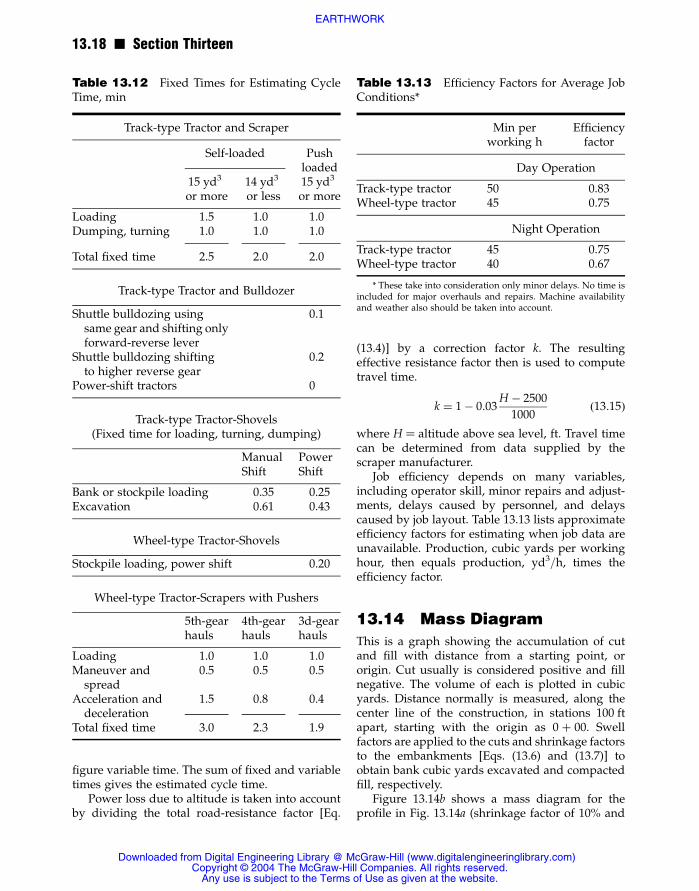
figure variable time. The sum of fixed and variabletimes gives the estimated cycle time.
Power loss due to altitude is taken into accountby dividing the total road-resistance factor [Eq.
(13.4)] by a correction factor k. The resultingeffective resistance factor then is used to computetravel time.
k ¼ 1� 0:03H � 2500
1000(13:15)
where H ¼ altitude above sea level, ft. Travel timecan be determined from data supplied by thescraper manufacturer.
Job efficiency depends on many variables,including operator skill, minor repairs and adjust-ments, delays caused by personnel, and delayscaused by job layout. Table 13.13 lists approximateefficiency factors for estimating when job data areunavailable. Production, cubic yards per workinghour, then equals production, yd3/h, times theefficiency factor.
13.14 Mass Diagram
This is a graph showing the accumulation of cutand fill with distance from a starting point, ororigin. Cut usually is considered positive and fillnegative. The volume of each is plotted in cubicyards. Distance normally is measured, along thecenter line of the construction, in stations 100 ftapart, starting with the origin as 0 þ 00. Swellfactors are applied to the cuts and shrinkage factorsto the embankments [Eqs. (13.6) and (13.7)] toobtain bank cubic yards excavated and compactedfill, respectively.
Figure 13.14b shows a mass diagram for theprofile in Fig. 13.14a (shrinkage factor of 10% and
Table 13.12 Fixed Times for Estimating CycleTime, min
Track-type Tractor and Scraper
Self-loaded Pushloaded
15 yd3
or more14 yd3
or less15 yd3
or more
Loading 1.5 1.0 1.0Dumping, turning 1.0 1.0 1.0
Total fixed time 2.5 2.0 2.0
Track-type Tractor and Bulldozer
Shuttle bulldozing usingsame gear and shifting onlyforward-reverse lever
0.1
Shuttle bulldozing shiftingto higher reverse gear
0.2
Power-shift tractors 0
Track-type Tractor-Shovels(Fixed time for loading, turning, dumping)
ManualShift
PowerShift
Bank or stockpile loading 0.35 0.25Excavation 0.61 0.43
Wheel-type Tractor-Shovels
Stockpile loading, power shift 0.20
Wheel-type Tractor-Scrapers with Pushers
5th-gearhauls
4th-gearhauls
3d-gearhauls
Loading 1.0 1.0 1.0Maneuver andspread
0.5 0.5 0.5
Acceleration anddeceleration
1.5 0.8 0.4
Total fixed time 3.0 2.3 1.9
Table 13.13 Efficiency Factors for Average JobConditions*
Min perworking h
Efficiencyfactor
Day Operation
Track-type tractor 50 0.83Wheel-type tractor 45 0.75
Night Operation
Track-type tractor 45 0.75Wheel-type tractor 40 0.67
* These take into consideration only minor delays. No time isincluded for major overhauls and repairs. Machine availabilityand weather also should be taken into account.
13.18 n Section Thirteen
Downloaded from Digital Engineering Library @ McGraw-Hill (www.digitalengineeringlibrary.com)Copyright © 2004 The McGraw-Hill Companies. All rights reserved.
Any use is subject to the Terms of Use as given at the website.
EARTHWORK

swell factor of 20% included). Between 0 þ 00 and1 þ 00, there is a cut of 2000 yd3. This is plotted at1 þ 00. Between 1 þ 00 and 2 þ 00, there is a cut of5000 yd3, making a total of 7000 yd3 between0 þ 00 and 2 þ 00; 7000 is plotted at 2 þ 00. At4 þ 00, there is a total accumulation of 18,000 yd3 ofcut. Between 4 þ 00 and 5 þ 00, there are 1000 yd3
of cut and 550 yd3 of embankment (corrected forshrinkage), making a net accumulation of
18,000þ 1000� 550 ¼ 18,450 yd3
From 6 þ 00 to 12 þ 00, there is mostly embank-ment, and the accumulation decreases to212,000 yd3. Cut follows, then some more em-bankment. At the end of the construction, 20 þ 00,there is a net of 24300 yd3 embankment that mustbe obtained from borrow.
If a mass curve is horizontal between stations,the implication is that no material has to be moved
in that stretch. Actually, there may be cuts and fillsbut they balance. If work consists of side-hill cutsand fills, the mass diagram tends to flatten becausethe cuts can be moved into the fills and not movedfrom one station to another. Moving excavationfrom one side of the center line to the other is calledcross haul.
The slope of the mass curve increases withvolume between stations. An ascending masscurve indicates cut; a descending diagram, fill. Thecurve reaches a maximum where cut ends and fillbegins, and a minimum where fill ends and cutbegins.
If a mass diagram is intersected by a horizontalline, cuts balance fills between the points ofintersection. If the mass curve loops above theline, cuts will have to be hauled forward (inthe direction of increasing stations) for the em-bankments; if the diagram lies below thehorizontal line, the haul will have to be back-ward.
Fig. 13.14 Profile and mass diagram for cut and fill for grading a highway.
Earthwork n 13.19
Downloaded from Digital Engineering Library @ McGraw-Hill (www.digitalengineeringlibrary.com)Copyright © 2004 The McGraw-Hill Companies. All rights reserved.
Any use is subject to the Terms of Use as given at the website.
EARTHWORK

Haul, station-yards, for a section of earthwork isthe product of the amount of excavation, cubicyards, and the distance it is moved, stations. Totalhaul is the product of total amount of excavationhauled and average haul distance. The area betweenthe mass diagram and a balancing (horizontal) lineequals the haul, station-yards, between the twopoints cut by that line. Average haul distance equalsthe area between the mass diagram and thebalancing line divided by the total cut (maximumordinate) between the points of intersection.
Center of mass of cut and fill can be determinedfrom the mass diagram. Draw the maximumordinate between a balancing line and the curve(for example, BA in Fig. 13.14b). Then, draw ahorizontal line (HJ) through the midpoint of thatordinate, and note the stations at the points ofintersection with the curve. The station (H) on theincreasing portion of the diagram is the center ofmass of cut; the station ( J) on the decreasing por-tion, the center of fill. The distance between thestations is the haul distance.
If the mass curve terminates below thehorizontal axis, borrow is required. If thecurve ends above the axis, excavation must bewasted.
Free haul is the distance excavation may bemovedwithout an increase in contract price; that is,the unit bid price for excavation applies only tohaul distances less than free haul. Overhaul is hauldistance exceeding free haul. The bid price foroverhaul usually is given in terms of dollars perstation-yard.
Example 13.4: For Fig. 13.14, if free haul is 300 ft.determine the overhaul between 9 þ 10 and15 þ 60.
Draw horizontal line DE with length 300 ftbetween two points on the mass curve. Drawordinates FD at D and GE at E. These vertical linesset the limits of free haul. Next, the center of massof cut and fill outside these limits must be found.To do this, draw a horizontal line through themidpoints of FD and GE intersecting the masscurve at K and L. The center of mass of cut is at L,14 þ 70, and of fill, at K, 9 þ 50. KL ¼ 5.2 stationsrepresents the average haul distance. Hence, theoverhaul equals the product of DF ¼ 9500 yd3 andKL less the free-haul distance (5.2 2 3.0), or 20,900station-yards.
(C. F. Allen, “Railroad Curves and Earthwork,”McGraw-Hill Book Company, New York.)
13.15 Drilling for RockExcavation
Usually, before rock can be excavated, it must beblasted into pieces small enough for efficienthandling by available equipment. To place explo-sive charges for this purpose, holes have to bedrilled into the rock. This is done with percussionor rotary drills. Percussion generally is used forhard rock and small-diameter holes. Maximum sizeof bit for percussion drills is about 6 in. Larger bitsmay be used on rotary drills (Fig. 13.15), but theyrarely exceed 9 in in diameter.
Normally, percussion drills are mounted on self-propelled crawlers (Fig. 13.16). Drilling commonlyis done with sectional drill steel and carbide-insertbits, both of which have to be rugged. A bit has firstto crush its way into the rock. Next, the hole mustbe reamed. Finally, the cuttings are mixed and
Fig. 13.15 Track-mounted rotary drill with aircompressor. (Caterpillar Tractor Co.)
13.20 n Section Thirteen
Downloaded from Digital Engineering Library @ McGraw-Hill (www.digitalengineeringlibrary.com)Copyright © 2004 The McGraw-Hill Companies. All rights reserved.
Any use is subject to the Terms of Use as given at the website.
EARTHWORK

blown from the hole by compressed air fed througha hole in the center of the drill steel and dischargedthrough holes in the bit. Hard rock requires a bitwith good crushing or penetrating and reamingability. Shales, usually soft, require a bit that mixesmaterial fast. The bit does not need to have goodcrushing ability. For sandstone, the gage willusually be destroyed first or the bit will lose itsreaming ability. A bit used in sandstone must haveexceptional reaming ability plus good mixingfeatures.
The best way to determine how well a bit isperforming is to inspect the chips. They should befirm pieces of rock, not dust. When cuttings aredust, usually the chips are not being blown fromthe hole until they have been reground severaltimes. This causes more than normal bit wear. Lowair pressure also may produce excessive dust.Pressure at the drill should be at least 90 psi. Whencomputing the pressure, take into account the dropin pressure due to friction in the hose.
Rotary drilling is more suitable for large holes.With low-cost ammonium nitrate and fuel oil asthe explosive, economical production results. Withlarge holes, spacing can be greater and more cubicyards can be produced per foot of hole. Whendetermining whether to use large or small holes,the engineer should bear in mind that the amountof explosives is directly proportional to the area ofthe hole.
In rotary drilling, it is essential to maintainsufficient down pressure, rotation speed, andvolume and pressure of air used to blow cuttingsout of the hole or excessive bit wear and lowproduction results. Down pressure should be at
least 5000 psi/in of bit diameter. Rotation speedshould be the largest possible without regrindingchips before they are blown out of the hole.Therefore, rotation speed depends on air volume.Air is blown through the center of the drill steel anddischarged through passages in the bit. Except inextremely deep holes, 40 psi usually is enoughpressure to clean holes.
13.16 Explosives for RockExcavation
Explosives are used to blast rock into pieces smallenough to be handled efficiently by availableequipment. The charges usually are set in holesdrilled into the rock (Art. 13.15) and detonated.
If the reaction is instantaneous or extremely rapidover the entire mass of the explosive, detonation hasoccurred. Deflagration, however, takes place whenthe reaction particlesmove away from the unreactedparticles or the material burns. The basic differencebetween these two reactions is that detonation pro-duces a high-pressure shock wave that is self-prop-agating throughout the charge.
Several factors contribute to the effectivenessof an explosive charge: confinement, density, mostefficient uniform propagation diameter, and criticalmass.
Confinement helps the reacted products con-tribute to detonation of the unreacted products. Ifthe reacted portions can escape, the reactions willcease. An air space can be very effective in dam-pening a reaction.
The denser the mass of the charge, the moreeffective it will be, up to a point. For every explo-sive, there is an optimum density. Since drillingcosts more than explosives per cubic yard ofexcavation, it is desirable to use as many pounds ofexplosive per foot of borehole as possible.
The most efficient uniform propagation diam-eter is the width or length over which the explosivemass will be self-propagating after detonationstarts. This length ranges from very small to about9 in for ammonium nitrate.
The self-propagating diameter can be loweredby the overdrive method. Overdrive is the ability ofan explosive to detonate at a rate greater than theself-propagating detonating rate. Suppose, forexample, an explosive that detonates at 21,000 ft/sis set off in contact with another type of explosivethat detonates at 12,000 ft/s. Then, the slower
Fig. 13.16 Percussion drill powered by an aircompressor and mounted on a tractor. (CaterpillarTractor Co.)
Earthwork n 13.21
Downloaded from Digital Engineering Library @ McGraw-Hill (www.digitalengineeringlibrary.com)Copyright © 2004 The McGraw-Hill Companies. All rights reserved.
Any use is subject to the Terms of Use as given at the website.
EARTHWORK

explosive will detonate at more than 12,000 ft/s butless than 21,000 ft/s for a given distance, usuallyless than 2 ft.
Sensitivity of an explosive is very importantfrom a safety standpoint. An explosive should beeasy to detonate by specific methods, but hard orimpossible to set off with normal or careful han-dling during manufacture, shipment, storage, andpreparation for detonation.
Critical mass is that amount of an explosive thatmust be present for the reaction to change fromdeflagration to detonation. This mass is very smallfor high-order explosives but about 123 tons forammonium nitrate.
Explosive manufacturers generally balance theingredients of their products to get maximum gasvolume. This usually depends on the amount ofoxygen available from an unstable oxidizer in theexplosive. A combination of gas ratio and brisance(shattering effect) is called power factor. Explosiveingredients can be combined many ways to pro-vide almost any power factor.
Rate of detonation is a rough measure of theshattering ability of an explosive. Mass formationsof rock require a rate of at least 12,000 ft/s. Maxi-mum detonating rate for commercial explosives is26,000 ft/s.
Explosive strength generally is rated by thepercent of nitroglycerin or equivalent in explosivepower contained in an explosive. Straight dyna-mites contain only nitroglycerin and an inertingredient. In an ammonia dynamite, some of thenitroglycerin is replaced by other ingredients, suchas ammonium nitrate. Explosive power may bedenoted by weight strength or bulk or cartridgestrength. When weight strength is given, anammonia dynamite will have the same explosivepower as a straight dynamite of the same strength.Following are important features of explosivescommonly used in construction:
Gelatin Dynamites n Weight strength from100 to 60%. Detonation rate from 26,200 to19,700 ft/s, respectively. Suitable for submarineblasting or for use where considerable waterpressure will be encountered. Inflammable. Hashigh shattering action.
Gelatin Extras n Weight strength from 80 to30%. Detonation rate from 24,000 to 15,000 ft/s,respectively. Ammonium nitrate replaces part of
nitroglycerin. Gelatin extras have less waterresistance than gelatins but can be used satisfac-torily except under the most severe conditions.
Extra Dynamites n Weight strength from 60to 20%. Detonation rate from 12,450 to 8200 ft/s.Ammonium nitrate replaces part of nitroglycerin.Extra dynamites can be used in average waterconditions if properly wrapped with waterproof-ing. They usually are called original ammoniadynamites.
Semigelatins n Weight strength from 65 to40%; bulk strength from 65 to 30%. Detonationspeed from 17,700 to 9850 ft/s. Higher detonationspeeds for larger-diameter cartridges. Can be usedinstead of gelatins in most blasting uses. Waterresistance is adequate for average conditions.
High-Ammonium-Nitrate-Content Dyna-mites n Weight strength from 68 to 46%; bulkstrength from 50 to 20%. Detonation speed from10,500 to 5250 ft/s. Has low water resistance butcan be used if fired within a relatively short time ofexposure.
Boosters or Primers n Have high density.Detonation speed of 25,000 ft/s. Used to detonateammonium nitrates and fuel oil or any non-cap-sensitive explosive because boosters and primershave a very high detonation pressure.
Detonating Cord n Used as a fuse. Has high-explosive core that detonates at 21,000 ft/s withsufficient energy to detonate another, less sensitiveexplosive alongside in a borehole. When strungfrom top to bottom of a hole, detonating cord willact as a detonating agent throughout the length ofthe hole.
Ammonium nitrate, for best results, should bemixed with at least 6% fuel oil, by weight. The oil isadded for oxygen balancing and to lower theself-propagating diameter. Quantities of fuel oilgreatly in excess of 6% have a dampening effect onthe explosion. By use of the overdrive method, therate of detonation for ammonium nitrate andfuel oil will be sufficient to shatter any rock for-mation encountered. Ammonium nitrate plus 10%booster has a rate of 4500 to 10,000 ft/s; when fueloil is added, the rate increases to 10,000 to16,500 ft/s. For overdrive, best results are obtained
13.22 n Section Thirteen
Downloaded from Digital Engineering Library @ McGraw-Hill (www.digitalengineeringlibrary.com)Copyright © 2004 The McGraw-Hill Companies. All rights reserved.
Any use is subject to the Terms of Use as given at the website.
EARTHWORK

with at least 5% of a primer with a high detona-tion rate. The primers should be properly spaced toensure that critical propagation length will not beexceeded and detonation will occur throughout.
Special precautions should be observed whenoverdrive is used. If free fuel oil is available in themixture, an ammonia dynamite should not be usedas a primer. Fuel oil will desensitize ammonia dyna-mite, and a partial or complete failure will result.Fuel oil also has an adverse effect on the explosivecontained in detonating cord. This, however, can beavoided by using a plastic coating on the cord.
Table 13.14 gives the approximate amount ofammonium nitrate to use per foot of borehole. Thetable assumes a density of 47 lb/ft3 for ammoniumnitrate and fuel oil.
Ammonium nitrate is soluble in water. It de-velops some water resistance when mixed with
fuel oil. But exposure to water results in loss ofefficiency, and detonation becomes difficult.
13.17 Rock Excavation byBlasting
To secure the desired shape of rock surface afterblasting, explosive charges must be placed in bore-holes laid out in the proper pattern and of sufficientdepth. (See also Arts. 13.15 and 13.16.) Before thepattern is chosen, an explosive factor must beselected (Table 13.15).
Next, drill size, burden, and spacing can beselected. Then, the amount of stemming can bedetermined. Stemming is the top portion of a bore-hole that contains a tightly tamped backfill, notexplosive. Since an explosive exerts equal pressurein all directions, depth of stemming should notexceed the width of burden. Burden is the distancefrom the borehole to the rock face. Burden distanceshould be less than the hole spacing so thatthe blasted rock will be thrown in the direction ofthe burden.
Holes should be placed in lines parallel to therock face because a rectangular pattern gives betterbreakage and vibration control. Depth of drill holesis determined by height of face desired and thedistance it is necessary to drill below grade so thatthe bottom can be controlled.
A mathematical check should be made todetermine that the explosive factor is correct forthe burden and spacing selected. If properlyblasted rock is not produced when a drill patternis tried, a new spacing or burden width should betried. It is best to vary only one dimension at a timeuntil desired fragmentation is obtained.
Delay caps may be used on the explosivecharges for better fragmentation and vibrationcontrol. Delay caps permit detonation of explosivecharges in different holes at intervals of a fewmilliseconds. The result is better fragmentation,
Table13.14 Amount ofAmmoniumNitrate perFoot of Borehole
Hole dia.,in
Approx. weight,lb per ft
Approx. volume,ft3 per ft
2 1.02 0.021821⁄4 1.29 0.027521⁄2 1.59 0.0343 2.30 0.049
31⁄4 2.67 0.05731⁄2 3.00 0.0644 4.09 0.087
41⁄2 5.17 0.1105 6.39 0.136
51⁄2 7.75 0.1656 9.21 0.196
61⁄4 10.01 0.21361⁄2 10.81 0.23067⁄8 12.03 0.2567 12.54 0.267
71⁄4 13.44 0.28677⁄8 15.79 0.3368 16.40 0.349
81⁄2 18.51 0.3949 20.72 0.441
91⁄2 23.12 0.49210 25.61 0.545
101⁄2 28.24 0.60111 30.97 0.659
111⁄2 33.88 0.72112 36.89 0.785
Table 13.15 Explosive Factors
Types of rock Explosive factor, lb/yd3
Shales 0.25–0.75Sandstone 0.30–0.60Limestone 0.40–1.00Granite 1.00–1.50
Earthwork n 13.23
Downloaded from Digital Engineering Library @ McGraw-Hill (www.digitalengineeringlibrary.com)Copyright © 2004 The McGraw-Hill Companies. All rights reserved.
Any use is subject to the Terms of Use as given at the website.
EARTHWORK

controlled throw, and less back break since betterdisplacement is obtained. Table 13.16 gives charac-teristics of short-period delay caps. Use of regulardelays is not recommended because of “holerobbing” and uncontrolled throw.
Presplitting is a technique for producing areasonably smooth, nonshattered wall, free fromloose rock. An objective is to hold maintenance ofslopes and ditches to a minimum. Presplit holes aredrilled in a single line in a plane that will be thefinal slope or wall face. Line drilling also may beused, with holes spaced about two times the bitdiameter. But for presplitting, the spacing is muchgreater. Dynamite, evenly spaced on detonatingcord, is exploded to break the web between holes.Manufacturers can furnish explosives made for
presplitting. When this type of explosive is used,loading of holes is easier since no detonating cordis required. The resulting saving of labor willusually more than offset additional explosive costs.
Percussion drills commonly are used for drillingpresplitting holes. An air track with hydrauliccontrols is very effective in enabling the driller tomove from hole to hole and reset the drill in aminimum time. Number of drills required varieswith capacity of loading shovel, width of cut, andspacing of presplit holes.
For presplitting, 40% extra gelatin workssatisfactorily. This explosive has a detonation speedthat can break the hardest rock formations and isadequate under the most adverse conditions.Speed of detonation should not be less than15,000 ft/s for presplitting.
Figure 13.17a shows a presplit hole loaded with11⁄4� 8-in cartridges spaced 18 to 24 in apart on
Fig. 13.17 Drill holes loaded with (a) 11⁄4� 8-incatridges and (b) 11⁄4� 4-in catridges on detonationcord for presplitting. Prepackaged explosives areavailable from explosive manufacturers.
Table 13.16 Characteristics of MillisecondDelay Caps*
Delayperiod
Nominal firingtime, ms
Interval betweendelay periods, ms
0 12SP-1 25 13SP-2 50 25SP-3 75 25SP-4 100 25SP-5 135 35SP-6 170 35SP-7 205 35SP-8 240 35SP-9 280 40SP-10 320 40SP-11 360 40SP-12 400 40SP-13 450 50SP-14 500 50SP-15 550 50SP-16 600 50SP-17 700 100SP-18 900 200SP-19 1100 200SP-20 1300 200SP-21 1500 200SP-22 1700 200SP-23 1950 250SP-24 2200 250SP-25 2450 250SP-26 2700 250SP-27 2950 250
* Courtesy of Hercules Powder Co.
13.24 n Section Thirteen
Downloaded from Digital Engineering Library @ McGraw-Hill (www.digitalengineeringlibrary.com)Copyright © 2004 The McGraw-Hill Companies. All rights reserved.
Any use is subject to the Terms of Use as given at the website.
EARTHWORK

primacord; Fig. 13.17b shows 11⁄4 � 4-in cartridgeson 12- to 18-in spacing. Table 13.17 indicates thenumber of pounds of 40% gelatin extra required toproduce a wall 25 ft high by 100 ft long.
Presplitting should precede the primary blast.Some locations, however, preclude this; for exam-ple, a side hill where there would not be sufficientburden in front of the presplit holes. In such a case,presplitting will be accomplished, but the burdenin front will be shifted, causing loss of primaryblast holes or difficult drilling if the holes were notdrilled previously. If a sidehill condition exists,delay caps should be used to ensure that pre-splitting is done before detonation of the primaryblast.
Spacing of holes for presplitting varies con-siderably with material, location, and method ofprimary blasting. Spacings up to 6 ft have been
found adequate where no restrictions are imposedon explosives and primary blasting can be adjustedto obtain correct balance for removal of materialwithin the walls. Obtaining a good wall is the resultof balancing primary blasting with as wide aspacing as possible for the type of rock. Use of closespacing of holes without consideration of otherfactors may be wasteful and not yield best overallresults.
Spacing of presplit holes and charges for bestresults may be determined by trial. Vary only onevariable at a time. For example, initially drill theholes for 25 ft of wall 18 in apart and detonate.Then, for the next 25 ft of wall, drill the holes 24 inon centers and detonate with the same loading.Continue increasing the spacing until a maximumis reached. Next, vary the charge. If too muchdynamite is used, the resulting surface between
Fig. 13.18 Drill pattern for conventional blasting with holes all of the same diameter. Numbersindicate order of firing with delays.
Table 13.17 Pounds of 40% Gelatin Extra to Produce 2500 ft2 of Wall by Presplitting
Hole Spacing11⁄4 � 8-in cartridges 11⁄4 � 4-in cartridges
18 in c to c 24 in c to c 12 in c to c 18 in c to c
18 362 272 272 18124 270 203 203 13530 215 161 161 10836 178 134 134 8942 152 114 114 7648 132 99 99 6654 117 88 88 5860 105 79 79 5266 95 71 71 4772 86 64 64 43
Earthwork n 13.25
Downloaded from Digital Engineering Library @ McGraw-Hill (www.digitalengineeringlibrary.com)Copyright © 2004 The McGraw-Hill Companies. All rights reserved.
Any use is subject to the Terms of Use as given at the website.
EARTHWORK
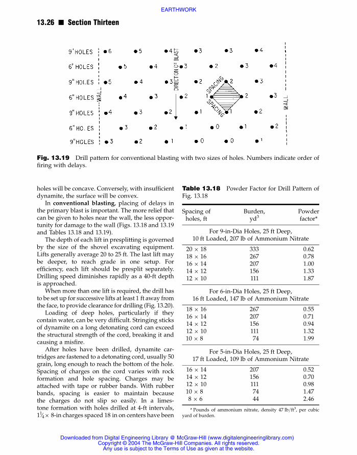
holes will be concave. Conversely, with insufficientdynamite, the surface will be convex.
In conventional blasting, placing of delays inthe primary blast is important. The more relief thatcan be given to holes near the wall, the less oppor-tunity for damage to the wall (Figs. 13.18 and 13.19and Tables 13.18 and 13.19).
The depth of each lift in presplitting is governedby the size of the shovel excavating equipment.Lifts generally average 20 to 25 ft. The last lift maybe deeper, to reach grade in one setup. Forefficiency, each lift should be presplit separately.Drilling speed diminishes rapidly as a 40-ft depthis approached.
When more than one lift is required, the drill hasto be set up for successive lifts at least 1 ft away fromthe face, to provide clearance for drilling (Fig. 13.20).
Loading of deep holes, particularly if theycontain water, can be very difficult. Stringing sticksof dynamite on a long detonating cord can exceedthe structural strength of the cord, breaking it andcausing a misfire.
After holes have been drilled, dynamite car-tridges are fastened to a detonating cord, usually 50grain, long enough to reach the bottom of the hole.Spacing of charges on the cord varies with rockformation and hole spacing. Charges may beattached with tape or rubber bands. With rubberbands, spacing is easier to maintain becausethe charges do not slip so easily. In a limes-tone formation with holes drilled at 4-ft intervals,11⁄4� 8-in charges spaced 18 in on centers have been
Table 13.18 Powder Factor for Drill Pattern ofFig. 13.18
Spacing ofholes, ft
Burden,yd3
Powderfactor*
For 9-in-Dia Holes, 25 ft Deep,10 ft Loaded, 207 lb of Ammonium Nitrate
20 � 18 333 0.6218 � 16 267 0.7816 � 14 207 1.0014 � 12 156 1.3312 � 10 111 1.87
For 6-in-Dia Holes, 25 ft Deep,16 ft Loaded, 147 lb of Ammonium Nitrate
18 � 16 267 0.5516 � 14 207 0.7114 � 12 156 0.9412 � 10 111 1.3210 � 8 74 1.99
For 5-in-Dia Holes, 25 ft Deep,17 ft Loaded, 109 lb of Ammonium Nitrate
16 � 14 207 0.5214 � 12 156 0.7012 � 10 111 0.9810 � 8 74 1.478 � 6 44 2.46
* Pounds of ammonium nitrate, density 47 lb/ft3, per cubicyard of burden.
Fig. 13.19 Drill pattern for conventional blasting with two sizes of holes. Numbers indicate order offiring with delays.
13.26 n Section Thirteen
Downloaded from Digital Engineering Library @ McGraw-Hill (www.digitalengineeringlibrary.com)Copyright © 2004 The McGraw-Hill Companies. All rights reserved.
Any use is subject to the Terms of Use as given at the website.
EARTHWORK

found adequate, whereas good results have beenobtained in soft shale with a 50% reduction in thecharge, to 11⁄4� 4 in, and the same hole spacing.Detonation cord from each hole is attached to a
trunk line, which when fired causes each hole todetonate instantaneously.
Stemming can be done several ways. In onemethod, after the charge has been placed in a hole,
Table 13.19 Powder Factor for Drill Pattern of Fig. 13.19
Hole dia, Hole depth, Load depth,Charge
in ft ft Lb Lb per ft
5 25 17 108.63 6.396 25 16 147.36 9.219 25 10 207.20 20.72
Powder factor*
Spacing,ft
Burden,yd3
9-inholes
9- and 6-inholes
9- and 5-inholes
6-inholes
6- and 5-inholes
5-inholes
8 � 8 59 3.51 3.00 2.68 2.50 2.17 1.8410 � 10 93 2.23 1.91 1.70 1.58 1.38 1.1712 � 12 133 1.56 1.33 1.19 1.11 0.96 0.8214 � 14 194 1.07 0.91 0.81 0.76 0.66 0.5616 � 16 237 0.87 0.75 0.67 0.62 0.54 0.4618 � 18 300 0.69 0.59 0.53 0.49 0.43 0.3620 � 20 370 0.56 0.48 0.43 0.40 0.35 0.2922 � 22 448 0.46 0.40 0.35 0.33 0.29 0.24
* Pounds of ammonium nitrate, density 47 lb/ft3, per cubic yard of rock.
Fig. 13.20 Placement of a drill in a multilift cut.
Earthwork n 13.27
Downloaded from Digital Engineering Library @ McGraw-Hill (www.digitalengineeringlibrary.com)Copyright © 2004 The McGraw-Hill Companies. All rights reserved.
Any use is subject to the Terms of Use as given at the website.
EARTHWORK

clean stone chips or sand that will pass a 3⁄8-instandard sieve is placed on top. For best results, thestemming should be worked around the charges byholding the end of the detonation cord in the centerof the hole and working it up and down. Anotherstemming method is to push newspaper into thehole until it reaches the top charge. On top of thepaper, the hole is stemmed with drill cuttings orother suitable available material.
In most blasting procedures, it is good practiceto have as much confinement as possible. Inpresplitting, some means must be provided toallow excess gases to escape. Use of detonationcord and top firing produces best results. Mostinstant blasting caps have so much delay thatbreakage occurs in the wall if they are used. Toreduce noise and vibration, delay connectors maybe used between groups of two or more holes.
The cost of presplitting per cubic yard excavateddepends on the distance between walls or volumeto be removed per square foot of presplit wall.Presplitting eliminates the need for small-diameterholes for a primary blast, moving of material frombehind a pay line, and scaling of slopes. Ifpresplitting is not required and no pay will bereceived for material excavated behind a pay lineset 18 in beyond the design slope, then, to controlexcess excavation, small-diameter blast holeswould be drilled near the slope at a minimumspacing of 6 ft. These holes would be the samediameter as presplit holes in most cases. Usually,two rows of these holes would be required. Theprimary blast holes would be at a greater distancefrom the design slope than for presplitting. Whenpresplitting is used, the spacing of the primaryblast holes can be rearranged to produce well-broken rock that will load more easily at less cost.
A cost comparison between presplitting andconventional blasting should compare the cost ofblasting the entire cut without presplitting with thecost of presplitting, rearranging the primary blast,and shooting. Generally, presplitting will cost less.For most formations, this will be true when theratio of cubic yards excavated to square feet ofpresplit wall exceeds 1.5 :1.
13.18 Vibration Control inBlasting
Explosive users should take steps to minimizevibration and noise from blasting and protectthemselves against damage claims.
Before blasting, an explosive user shouldconduct a survey of nearby structures. Experi-enced, qualified personnel should make thissurvey. They should carefully inspect everystructure within a preselected distance, at least500 ft. for cracks, deformation from any cause, andother damage that could be claimed. They shouldmake a written report of all observations, wall bywall, and take pictures of all previous damage. Thisis known as a preblast survey and should be welldocumented for future use in case of a claim.
Any rock excavation project is a part of somecommunity and has an effect on the surroundingenvironment. The explosive user can be a goodneighbor, enjoying that position, or an undesirableone and suffer the consequences. The decision as towhether the explosive user is an asset or a liabilityis not made by people familiar with blastingproblems. Quarries and rock excavation projects,therefore, should be operated with the realizationthat any right to exist will have to be proved bybehavior acceptable to the community.
To be a good neighbor, an explosive user mustnot make noise, create vibrations, or throw pro-jectile rocks. The first and last factors are easy tocontrol if proper supervision and good guidanceare used. If a neighbor does not hear or see theblast, annoyance is greatly diminished.
Noise and throw are best controlled duringdrilling and loading cycles. No explosives shouldbe loaded closer to the ground surface than theleast dimension used for drill-hole spacing. Inother words, put explosives in the bottom of holesand use as much stemming as possible; when noiseoccurs, energy has been wasted. Using larger holes,with resulting wide spacing, will usually produceoversize stone in the top of the shot. This can becontrolled by the use of small (satellite) holesdrilled to a shallow depth, below the top of theexplosives, between large-diameter holes. This isone method used to get explosives evenly dis-tributed.
Extreme care should be exercised with detonat-ing cord. Nothing makes a sharper and more star-tling noise. When detonating cord is demanded, alow-noise-level cord should be used, and it shouldbe covered with some material that will not contam-inate the desired product. Considerable depth ofcovering is required to control noise: Experiencedictates not less than 3 ft for 1⁄4-cord.
Knowledge of human habits and how to use thesurrounding environment will greatly help reduce
13.28 n Section Thirteen
Downloaded from Digital Engineering Library @ McGraw-Hill (www.digitalengineeringlibrary.com)Copyright © 2004 The McGraw-Hill Companies. All rights reserved.
Any use is subject to the Terms of Use as given at the website.
EARTHWORK

complaints. Set off blasts while people are busywith their daily tasks. Bear in mind that weatherconditions affect noise transmission. Blastingduring cloudy, overcast weather is like shootingin a room that has a roof. Use other noise- andvibration-producing elements of the surroundingenvironment for dampening or overriding effects,for example, scheduling and performing blastswhile a freight train passes or while a jet airplane istaking off.
Vibrations caused by blasting are propagatedwith a velocity V, ft/s, frequency f, Hz, and wave-length L, ft, related by
L ¼ V
f(13:16)
Velocity v, in/s, of the particles disturbed by thevibrations depends on the amplitude of the vibra-tions A, in.
v ¼ 2pfA (13:17)
If the velocity v1 at a distanceD1 from the explosionis known, the velocity v2 at a distance D2 from theexplosion may be estimated from
v2 � v1D1
D2
� �1:5
(13:18)
The acceleration a, in/s2, of the particles is given by
a ¼ 4p2f 2A (13:19)
For a charge exploded on the ground surface, theoverpressure P, psi, may be computed from
P ¼ 226:62W1=3
D
� �1:407
(13:20)
where W ¼ maximum weight of explosives, lb perdelay
D ¼ distance, ft, from explosion toexposure
The sound pressure level, decibels, may be com-puted from
dB ¼ P
6:95� 10�28
� �0:084
(13:21)
For vibration control, blasting should be controlledwith the scaled-distance formula:
v ¼ HDffiffiffiffiffiW
p� ��b
(13:22)
where b ¼ constant (varies for each site)
H ¼ constant (varies for each site)
Distance to exposure, ft, divided by the square rootof maximum pounds per delay (Fig. 13.21) isknown as scaled distance.
Most courts have accepted the fact that a particlevelocity not exceeding 2 in/s will not damage anypart of any structure. This implies that, for thisvelocity, vibration damage is unlikely at scaleddistances larger than 8 (see Fig. 13.22).
Without specific information about a particularblasting site, the maximum weight of explosivesper delay should conform with explosive weightand distance limits to prevent vibration damage.This conforms with a scaled distance of 50 orgreater without known facts (Fig. 13.21).
To control vibration, the scaled-distance for-mula should be applied for each blasting location.If formations vary around the site, each formationwill have a different formula, which should becomputed. The more blasts used in determiningthe formula constants, the more accurate thescaled-distance formula becomes. Only two easilydetermined factors must be known: distance fromseismograph and maximum weight of explosiveused with any delay. Once a safe scaled distancehas been determined, the need to use a seis-mograph for vibration measurements of futureblasts is unlikely. Particle velocity can be com-puted with actual measured distance and knownmaximum weight of explosives used with anydelay.
There is a direct relationship between particlevelocity (vibration) and number of complaintsexpected from families exposed. This is shown inFig. 13.23.
When a complaint is received, it should behandled firmly and expeditiously. Following aresome suggestions:
Assign one person the primary responsibilityfor handling complaints. This person should bemature and capable of communicating with com-plainants who are sincerely upset and afraid ofnot only property damage but bodily injury. Aminimum of two employees should, preferably,
Earthwork n 13.29
Downloaded from Digital Engineering Library @ McGraw-Hill (www.digitalengineeringlibrary.com)Copyright © 2004 The McGraw-Hill Companies. All rights reserved.
Any use is subject to the Terms of Use as given at the website.
EARTHWORK

be detailed because the primary employee maynot always be available. The primary employeeshould always be held responsible and informedof all complaints.
Before blasting begins, the public should beadvised about whom to contact for any infor-mation. When a complaint is received, record thecomplainant’s name, address, and telephonenumber. Ask at what time the blast was felt andheard. Ask if blast was felt or heard first. Was thecomplainant’s building included in the preblastsurvey?
Employees handling complaints should becourteous but firm, never apologizing or sayingthat fewer explosives will be used in the future.Never admit or imply any possible damage untilyour consultant has advised you of the findings.A completely informed public will want progress,and that is what your organization owes itssuccess to.
Inform the complainants that a consultingengineer has been retained to design and control
your blasting, and this consultant is concernedwith nothing but facts. This consultant has beenretained to protect the public, to help you do amore efficient job, and to inform the blaster ofany potential liability. An independent consultantwill know if and where damage may haveoccurred, probably before the property ownerdoes.
Emphasize that your organization does blast-ing as a normal operation and has enjoyedsuccess for a considerable length of time, that youhave very competent personnel with years ofexperience, and that you are producing work asefficiently as possible with the least inconve-nience to everyone.
People are afraid of noise made by explosives.Noise can be controlled by proper drilling, loading,and stemming. If a shot cannot be seen or heard,your complaints will be few. Remember, it takesonly one hole that is not properly tamped to blowout, and then everyone believes the entire shot wasnot controlled.
Fig. 13.21 Explosiveweight anddistance limits for prevention of damage from the vibrations of blasting.
13.30 n Section Thirteen
Downloaded from Digital Engineering Library @ McGraw-Hill (www.digitalengineeringlibrary.com)Copyright © 2004 The McGraw-Hill Companies. All rights reserved.
Any use is subject to the Terms of Use as given at the website.
EARTHWORK

Safe blasting is not only demanded and prac-tical, but essential.
13.19 Compaction
This is the process by which soils are densified. Itmay be done by loading with static weight, strikingwith an object, vibration, explosives, or rolling.Compaction is used to help eliminate settlementand to make soil more impervious to water.Compaction is costly, and for some embankments,the results cannot be justified because reducedsettlement and other desired benefits are noteconomical.
For a given soil and given compactive effort,there is an optimum moisture content, expressedin percent of soil dry weight, which gives thegreatest degree of compaction. ASTM D698,AASHTO T99, and a modified AASHTO methodare widely used for determining moisture content.The modified method may be specified if the soilengineer’s investigation indicates that T99 willnot yield the desired consolidation. In these tests,soil density of a compacted sample is plottedagainst percent of moisture in the sample. Maxi-mum density and optimum moisture for the sam-ple can be determined from the resulting curve(Fig. 13.24).
Fig. 13.22 Relationship between particle velocity (vibration) and scaled distance for a specific site forwhich H ¼ 5.2 and b ¼ 0.45 in Eq. (13.22). For a maximum particle velocity of 2 m/s, the scaled distanceis 8. Hence, vibration damage is unlikely at scaled distances larger than 8.
Earthwork n 13.31
Downloaded from Digital Engineering Library @ McGraw-Hill (www.digitalengineeringlibrary.com)Copyright © 2004 The McGraw-Hill Companies. All rights reserved.
Any use is subject to the Terms of Use as given at the website.
EARTHWORK

Compaction to be obtained on embankmentsis expressed as a percent of maximum density.For example, 90% compaction means that the soilin place in the field should have a density of90% of the maximum obtained in the laboratory.Moisture content should not vary more than 3%above or below optimum. To obtain proper com-
paction in the field, moisture must be control-led and compactive effort applied to the entirelift.
In-Place Density Tests n Several ASTMstandard test methods are available for determi-nation of soil density in the field. The two typesmost frequently used are nuclear methods (ASTMD2992), applicable for shallow depths, and thesand-cone, or calibrated-sand, method (D1556).
Nuclear methods offer the advantage over theothers in the relative ease with which the tests canbe made. They eliminate the need for digging holesand collecting samples. More tests can be carriedout per day than by the other methods. Also, theyhave the advantage of being more nearly non-destructive tests, thus permitting immediate detec-tion of apparent erratic measurements. Sincenuclear methods measure density of the soil nearthe surface, however, they preclude examination ofthe soil in depth.
Fig. 13.23 Public reaction to blasting is indicated by the percentage of the total number of familiesexposed to a specific particle velocity that should be expected to complain, plotted to a logarithmicscale.
Fig. 13.24 Maximum-density graph.
13.32 n Section Thirteen
Downloaded from Digital Engineering Library @ McGraw-Hill (www.digitalengineeringlibrary.com)Copyright © 2004 The McGraw-Hill Companies. All rights reserved.
Any use is subject to the Terms of Use as given at the website.
EARTHWORK

In these tests, a gamma-ray source and agamma-ray detector placed on, into, or adjacentto the soil to be tested are used to determine thetotal or wet density of the soil. A counter or scalercapable of automatic and precise timing isgenerally used to report the rate at which gammarays emitted by the source and modified by the soilarrive at the detector. This rate depends partly onthe density of the underlying soil. The scalerreading is converted to measured wet density withthe aid of a calibration curve that relates soildensity to nuclear count rate as determined bycorrelation tests of soils with known averagedensity. The nuclear methods are normally suitablefor test depths of about 2 to 12 in.
The sand-cone method is used to determine inthe field the density of compacted soils in earthembankments, road fill, and structure backfill, aswell as the density of natural soil deposits, aggre-gates, soil mixtures, or other similar materials. It isnot suitable, however, for soils that are saturated orsoft or friable (crumble easily). The methodrequires that a small hole be dug in the soil to betested. Hence, the soil should have sufficient co-hesion to maintain stable sides. It should be firmenough to withstand, without deforming orsloughing, the pressures involved in formingthe hole and placing the test apparatus over it.Furthermore, the hole should not be subjected toseepage of water into it.
All soil removed from the hole is weighed, anda sample is saved for moisture determination.
Then, the hole is filled with dry sand of knowndensity. The weight of sand used to fill the holeis determined and used to compute the vol-ume of the hole. Characteristics of the soil arecomputed from
Volume of soil, ft3 (13:23)
¼ weight of sand filling hole, lb
density of sand, lb=ft3
% moisture (13:24)
¼
100(weight of moist soil
�weight of dry soil)
weight of dry soil
Field density, lb=ft3 ¼ weight of soil, lb
volume of soil, ft3
(13:25)
Dry density ¼ field density
1þ% moisture=100(13:26)
% compaction ¼ 100(dry density)
max dry density(13:27)
Maximum density is found by plotting a density-moisture curve, similar to Fig. 13.25, and corre-sponds to optimum moisture. Table 13.20 listsrecommended compaction for fills.
Fig. 13.25 Types of dredges, (a) cutterhead; (b) trailing hopper; (c) grab; (d) dipper; (e) ladder.
Earthwork n 13.33
Downloaded from Digital Engineering Library @ McGraw-Hill (www.digitalengineeringlibrary.com)Copyright © 2004 The McGraw-Hill Companies. All rights reserved.
Any use is subject to the Terms of Use as given at the website.
EARTHWORK

A mistake commonly made in the field isapplication of compactive effort when eitherinsufficient or excessive moisture is present in thesoil. Under such conditions, it is impossible toobtain recommended compaction no matter howgreat the effort.
Compaction Equipment n Awide variety ofequipment is used to obtain compaction in the field(Table 13.21). Sheepsfoot rollers generally are usedon soils that contain high percentages of clay.Vibrating rollers are used on more granular soils.
To determine maximum depth of lift, make atest fill. In the process, the most suitable equip-ment and pressure to be applied, psi of ground
contact, also can be determined. Equipmentselected should be able to produce desiredcompaction with four to eight passes. Desirablespeed of rolling also can be determined. Averagespeeds, mi/h, under normal conditions are givenin Table 13.22. Compaction production can becomputed from
yd3=h ¼ 16WSLFE
P(13:28)
where W ¼ width of roller, ft
S ¼ roller speed, mi/h
L ¼ lift thickness, in
F ¼ ratio of pay yd3 to loose yd3
E ¼ efficiency factor (allows for timelosses, such as those due to turns):0.90, excellent; 0.80, average; 0.75,poor
P ¼ number on passes
Table 13.20 Recommended Compaction ofFills
Dry density,lb per ft3
Recommendedcompaction, %
Less than 90 —90–100 95–100100–110 95–100110–120 90–95120–130 90–95Over 130 90–95
Table 13.21 Compaction Equipment
Compactor type Soil best suited forMax effectin looselift, in
Densitygained in
lift*
Maxweight,tons
Steel tandem2–3 axle
Sandy silts, most granularmaterials, some clay binder
4–8 Average 16
Grid and tampingrollers
Clays, gravels, silts withclay binder
7–12 Nearly uniform 20
Pneumatic smalltire
Sandy silts, sandy clays,gravelly sands and clays,few fines
4–8 Uniform to average 12
Pneumatic largetire
All (if economical) To 24 Average 50
Sheepsfoot Clays, clay silts, silty clays,gravels with clay binder
7–12 Nearly uniform 20
Vibratory Sands, sandy silts, silty sands 3–6 Uniform 30Combinations All 3–6 Uniform 20
* Density diminishes with depth.
Table 13.22 Average Speeds, Mi/h, of Rollers
Grid rollers 12Sheepsfoot rollers 3Tamping rollers 10Pneumatic rollers 8
13.34 n Section Thirteen
Downloaded from Digital Engineering Library @ McGraw-Hill (www.digitalengineeringlibrary.com)Copyright © 2004 The McGraw-Hill Companies. All rights reserved.
Any use is subject to the Terms of Use as given at the website.
EARTHWORK

13.20 Dredging
Dredges are used for excavating in or under water.They may be classified by the method used forexcavation and the method of transporting anddisposing of the excavated material.
13.20.1 Methods of Excavation
Hydraulic, or suction, dredges are the most widelyused type of dredge. They move material bysuction and pumping through pipes.
Plain suction dredges often have the suctionpipe mounted in the bow. They may use water jetsto loosen the material to be moved. Plain suctiondredges perform well in sand. They remain sta-tionary and dredge a depression into which thesurrounding sand flows. They can dredge to adepth of 85 m.
Cutterheads are often used on suctiondredges to cut or loosen material to permithandling by the suction line and discharge pipes(Fig. 13.25a).
Trailing, or drag, dredges have the suction pipemounted on the side and extending toward thestern (Fig. 13.25b). This type of dredge, oftenemploying a draghead attachment and cutting asmall bank with each pass, is widely used formaintenance dredging of shoaling in navigationchannels.
Bucket, or mechanical, dredges excavate withgrab buckets, dippers, and bucket ladders.
Grab dredges (Fig. 13.25c), also known asclamshells or orange peels, are often used close toobstructions, such as docks, piers, and othermarine structures, and for the corner of cuts. Thesedredges can operate to large depths, limited onlyby the length of wire from the boom to the bucket.They perform well in silts and stiff mud. Per-formance is poor, however, in hard, consolidatedmaterials, and this type of dredge is not suitable forhard clays.
Dipper dredges are used for excavating brokenrock or hardmaterial (Fig. 13.25d). As is the case forpower shovels, operating depth is limited by thelength of boom.
Ladder dredges employ a continuous chain ofbuckets to excavate material and transport it to thedredges (Fig. 13.25e). Commonly used for sand andgravel dredging andmining, they also work well insoft clays and rock. Disadvantages of ladderdredges include high maintenance costs, inability
to operate in rough water, and the need formooring lines and anchors, which may interferewith navigation traffic.
Bucket dredges can cause considerable turbiditydue to material escaping from the buckets. Con-sequently, in some locations, bucket-dredge oper-ation is limited during “environmental windows,”such as fish migration periods.
13.20.2 Transportation and Disposal
Disposal of dredged material, often as difficult asthe dredging itself, is a serious concern.
Bucket dredges typically discharge dredgedmaterial into a scow or barge, into a hopper in thedredge itself, or onto an onshore disposal area, if itis within reach.
Pipeline dredges transport dredged material bydirect pumping through a floating pipeline to thedisposal area. They are normally referred to by thesize of their discharge pipeline.
Hopper dredges, floating counterparts of scra-pers, transport dredged material in the dredgehoppers to a disposal area. The hopper dredgesmay be unloaded by opening the hoppers andbottom-dumping the material or by pulling along-side a mooring barge at the disposal area andconnecting to a pipeline. Use of this type of dredgeis indicated in situations where the distance to adisposal area is too large to permit pumping thefull distance by pipeline. This type of dredge,however, has the disadvantage that it must stopexcavating during transport.
A third form of disposal is side casting dredgedmaterials in a direction that permits the current tocarry them away from the project area. Thismethod of disposal is used for dredging ofnavigation inlets to remove shoaling.
Water-injection dredging (WID), a newerdredging and disposal method, uses water injectedthrough jets in a horizontal pipe to fluidize fine-grained materials, such as sand and silt. Thefluidized sediment is carried away from the projectsite by a density current or natural currents. Forprojects characterized by fine sediments, favorablecurrents, and nearby deep water for reception ofdredged material, WID is an alternative toconventional dredging and disposal. Advantagesinclude low cost, no need for pipes to transportdredged material, and little disruption of naviga-tion traffic as would occur with conventionalpipelines. Also, turbidity is less with WID since the
Earthwork n 13.35
Downloaded from Digital Engineering Library @ McGraw-Hill (www.digitalengineeringlibrary.com)Copyright © 2004 The McGraw-Hill Companies. All rights reserved.
Any use is subject to the Terms of Use as given at the website.
EARTHWORK

fluidized material stays within about 2 ft of thebottom.
13.20.3 Dredge Production Rates
Prediction of production rates for dredges isextremely complex. Production rates depend onmany factors: soil type, uniformity, and grain size;digging depth, work-face height, tides and cur-rents, pipeline length, and disposal elevation;nearby navigation traffic; and equipment mainten-ance and crew training.
Measurement of dredging quantities for progressand payment also can be difficult. The standardmethod used by those who require dredging work(government officials, shippers, marina owners) isthe in situ volume based on pre- and postdredgingsurveys. Payment is made for dredging down to adesign depth and width, plus a tolerance.
A method of measurement more favorable todredge operators, however, is the volume or weighttransported by the dredging equipment. Unlessclose controls are maintained, this method israrely satisfactory to the paying authority, whodoes not want to pay for overexcavation beyondspecified dimensions.
Another method is to measure the dredged ma-terial after disposal. This, however, is suitable onlywhen the objective of the dredging is to create a fill.
13.20.4 Permits and Authorizations
A permit is needed for dredging in or over anynavigable water in the United States, in accord-ance with requirements of Section 10 of the 1899Rivers and Harbors Act. Also, Section 404 of theClean Water Act requires authorization forpractically all dredging discharges. These permitsare administered by the U.S. Army Corps ofEngineers.
13.21 EarthworkBibliography
J. E. Clausner, “Dredging Research,” vol. DRP-93-3, Nov 1993, U.S. Army Corps of Engineers,Waterways Experiment Station, Vicksburg, Miss.
J. F. Riddell, “Methods of Measurement forPayment Purposes,” Proceedings, MaintenanceDredging Conference, May 1987, Institution ofCivil Engineers, Bristol, U.K.
T. M. Turner, “Estimating Hydraulic DredgeCapacity,” Proceedings of the XIIth World Dred-ging Conference, 1989.
R. L. Nichols, “Moving the Earth—The Work-book of Excavation,” 3rd ed., McGraw-Hill, Inc.,New York (books.mcgraw-hill.com).
13.36 n Section Thirteen
Downloaded from Digital Engineering Library @ McGraw-Hill (www.digitalengineeringlibrary.com)Copyright © 2004 The McGraw-Hill Companies. All rights reserved.
Any use is subject to the Terms of Use as given at the website.
EARTHWORK