Embed Size (px)
Citation preview
IEEE JOURNAL ON SELECTED AREAS IN COMMUNICATIONS, VOL. 20, NO. 9, DECEMBER 2002 1613
Characterization of Ultra-Wide Bandwidth WirelessIndoor Channels: A Communication-Theoretic View
Moe Z. Win, Senior Member, IEEE,and Robert A. Scholtz, Life Fellow, IEEE
Invited Tutorial
Abstract—An ultra-wide bandwidth (UWB) signal propagationexperiment is performed in a typical modern laboratory/officebuilding. The bandwidth of the signal used in this experiment is inexcess of 1 GHz, which results in a differential path delay resolu-tion of less than a nanosecond, without special processing. Basedon the experimental results, a characterization of the propagationchannel from a communications theoretic view point is described,and its implications for the design of a UWB radio receiver arepresented. Robustness of the UWB signal to multipath fadingis quantified through histograms and cumulative distributions.The all Rake (ARake) receiver and maximum-energy-captureselective Rake (SRake) receiver are introduced. The ARakereceiver serves as the best case (bench mark) for Rake receiverdesign and lower bounds the performance degradation causedby multipath. Multipath components of measured waveforms aredetected using a maximum-likelihood detector. Energy capture asa function of the number of single-path signal correlators used inUWB SRake receiver provides a complexity versus performancetradeoff. Bit-error-probability performance of a UWB SRakereceiver, based on measured channels, is given as a function ofsignal-to-noise ratio and the number of correlators implementedin the receiver.
Index Terms—All Rake receiver (ARake), bit-error proba-bility (BEP), energy capture, propagation channel, selectiveRake (SRake) receiver, spread-spectrum, ultra-wide bandwidth(UWB).
I. INTRODUCTION
T ECHNIQUES for generating ultra-wide bandwidth(UWB) signals have been known for more than three
decades [1]. In the radar community, UWB techniques oftenare called “carrierless short pulse” techniques. A descriptionof early UWB work can be found in [2]. Recently, there hasbeen a renewed interest in utilizing this technology for UWB
Manuscript received September 12, 2002; revised October 31, 2002. Thiswork was supported in part by the Joint Services Electronics Program underContract F49620-94-0022, and in part by the Integrated Media Systems Center,a National Science Foundation Engineering Research Center and the NationalScience Foundation under Grant 9730556. This paper was presented in partat the IEEE International Symposium on Personal, Indoor, and Mobile RadioCommunications, Helsinki, Finland, September 1997, and in part at the IEEEInternational Conference on Communications, Montréal, Canada, June 1997.
M. Z. Win is with the Laboratory for Information and Decision Systems(LIDS), Massachusetts Institute of Technology, Cambridge, MA 02139 USA(e-mail: [email protected]).
R. A. Scholtz is with the Communications Sciences Institute, Departmentof Electrical Engineering-Systems, University of Southern California, Los An-geles, CA 90089-2565 USA (email: [email protected]).
Digital Object Identifier 10.1109/JSAC.2002.805031
spread-spectrum communications because of its fine delayresolution properties [3]–[16]. These fine delay resolutionproperties make UWB radio a viable candidate for communica-tions in dense multipath environments [17]–[19]. UWB radios,operating with low transmission power in an extremely largetransmission bandwidth, have also been under considerationfor future military networks because of their inherent covert-ness property with low probability of detection and intercept(LPD/LPI) capability [8]–[10].
Propagation environments place fundamental limitations onthe performance of wireless communications systems. The ex-istence of multiple propagation paths (multipath) with differentdelays produces a complex, often time-varying, transmissionchannel that limits the performance of wireless communicationssystems. A clear line-of-site path between the transmitter and re-ceiver seldom exists in indoor environments because of naturalor man-made blocking and one may have to rely on the signalarriving via multipath or propagating through blockages.
Communication channels have been characterized in termsof dual system functions in the time and frequency domains[20]. There have been texts containing a substantial amountof material on propagation channels [21]–[24] and some textsdevoted solely to this subject [25], [26]. Many indoor prop-agation measurements have been made with much narrowerbandwidth signals [27]–[34]. A description of early work onthe indoor propagation channels can be found in [34]. Char-acterization of indoor multipath, including angle of arrivalstatistics has been described in [35], [36]. Although the workdescribed in this paper does not cover outdoor propagationchannels, the selected works on outdoor propagation channelsare noted here for their measurement procedures and datareduction techniques [37]–[48].
Narrowband measurements are inadequate for the character-ization of UWB signal propagation channels. Specifically, asthe bandwidth of the channel probing signal increases, a com-posite propagation path (at low bandwidth) may be resolved intodistinguishable propagation paths (at high bandwidth) with dis-tinct propagation delays. This is equivalent to characterizing thechannel transfer function over a broader frequency range.
This paper describes an UWB signal propagation experimentperformed in a typical modern office building. A quasi-theo-retical/experimental analysis is described and its implicationsfor the design of UWB radio receivers are presented. The UWBpropagation analyses in the earlier publications [36], [49] arebased on the set of measurements described in this paper.
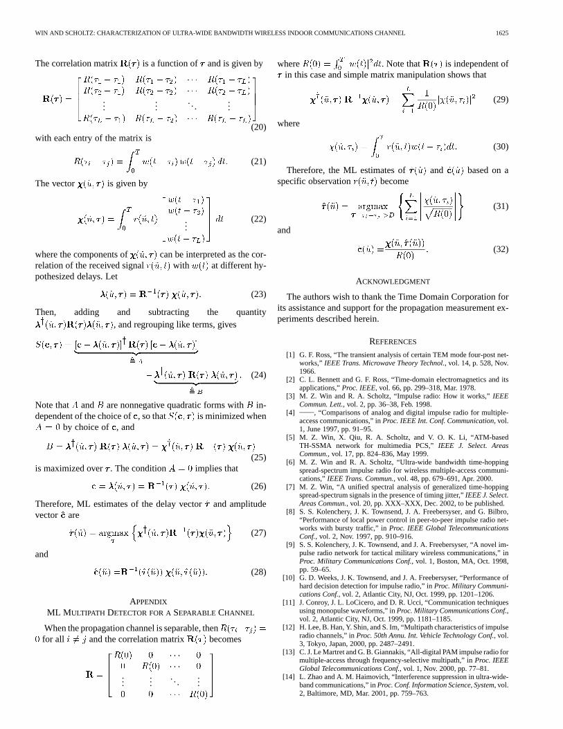
0733-8716/02$17.00 © 2002 IEEE

1614 IEEE JOURNAL ON SELECTED AREAS IN COMMUNICATIONS, VOL. 20, NO. 9, DECEMBER 2002
Fig. 1. A block diagram of the measurement apparatus.
II. UWB SIGNAL PROPAGATIONEXPERIMENT
A. Experimental Design
In our experiment, a short duration pulse of approxi-mately one nanosecond duration is transmitted as an excitationsignal of the propagation channel. The received signal repre-sents the superposition of distorted replicas of the excitationpulse at different amplitudes and delays. To the extent that theycan be identified, each individual path suffers different wave-form distortion effects that can occur in UWB signal propa-gation (e.g., low frequency emphasis in propagation throughmany materials, and high frequency emphasis in reflections offmetallic objects in many instances). Generally, the time varyingcharacteristic of the channel can be observed by periodic re-transmission of the probing pulse. The fixed pulse repetitiontime of this signal must be sufficiently short to characterize thetime varying nature of the individually propagating pulses, andlong enough to ensure that the multipath response of previouspulse transmissions has decayed before the next transmission.
The duration of a single pulse, inversely proportional tothe bandwidth of the transmission, determines themultipathresolution, i.e., the minimum differential path delay betweenindividual resolvable multipath components. The period of theperiodic pulse signal transmission determines the maximumobservable multipath delay. Hence, successive multipath com-ponents with differential delay greater than the width of thepulse and within one period of the periodic pulse transmissioncan be measured unambiguously.
To get maximum benefit from the propagation experiment,we assume that the channel-exciting pulse is the samewaveform that will be used as the fundamental building blockof a UWB radio modulation scheme. That is, in a UWB radioused for communication, the transmitted modulation will be asum of weighted and shifted copies of [3]–[6]. Under thereasonable assumption that the channel is linear and time-in-variant, this implies that the noise-free received signal in thecommunication receiver can be constructed from the noise-freereceived propagation measurement over the same channel.
B. Measurement Apparatus
A block diagram of the measurement apparatus is shown inFig. 1. It consists of a periodic pulse generator that transmitspulses at 500 ns intervals using a step recovery diode-basedpulser connected to a UWB antenna. A 500-ns pulse repeti-tion time was sufficient to capture all the significant multipaths
as will be shown in the next section. A transmitting antenna isconnected to the pulse generator via a coaxial cable, with fer-rite beads mounted at each end of the coaxial cable for isola-tion. The receiver consists of a vertically polarized receivingantenna, wideband low noise amplifier (LNA), attenuator, anddigital sampling oscilloscope (DSO). The attenuator provides asafety margin for the DSO and prevents the DSO from beingdamaged. Multipath profiles are captured by the DSO and sentover an interface bus to a personal computer for storage.
The triggering signal from the probe antenna, in close prox-imity to the transmit antenna, is supplied to the receiver appa-ratus by a longfixed-lengthcoaxial cable. The length of thiscoaxial cable is 200 feet and the propagation delay in the coaxialcable is measured to be 250.6 ns.1 Therefore, all recorded mul-tipath profiles have the same absolute delay reference, and pre-cise propagation delay measurements of the signals arriving atdifferent receiving antenna locations can be made.
Initial measurements indicated that some multipath responseprofiles contain significant energy beyond 250 ns dependingon the specific location of the transmitter and the receiver. Thismeans that the measurement window must be at least 250 nswide. However a DSO is only capable of capturing a certainnumber of samples in each measurement scan. Because of thelimited buffer size of the DSO, multipath data collected over alarge observation window would result in a large gap betweensamples. Therefore, 50-ns long windows of multipath data arecollected and later concatenated by a computer program toget a data record of the desired size with good resolution(fine detail in the delay domain). The DSO is set in such away that every 50-ns window of measurements contains 1024samples throughout the experiments. This implies that the timebetween samples is 48.828 ps and the equivalent sampling rateis 20.48 GHz. Therefore, according to the sampling theorem,any signals with bandwidth below 10 GHz can be reproducedfrom the samples collected by the DSO [50]–[56].
The DSO has the internal capability to average over severalreceived waveforms for noise reduction purposes. Taking ad-vantage of this capability, 32 sequentially measured multipathprofiles are averaged and recorded along with raw (unaveraged)multipath profiles at every measurement location. During eachof the multipath profile measurements, both the transmitter andreceiver are kept stationary. The multipath propagation channelis “frozen” during the measurement time by making sure thatpeople in the vicinity of the transmitter and receiving antennahave stopped moving. Indeed over 50% of the measurements arecollected during the evenings and weekends when most peopleare not present. To insure the quality of recorded data, everymultipath profile is inspected in detail using the zoom capa-bility of data acquisition software before storing for further datareduction.
C. Measurement Results
Propagation measurements were made on one floor of amodern laboratory/office building having the floor plan shownin Fig. 2. Each of the rooms is labeled alphanumerically. Walls
1Because the delay in the coaxial cable is longer than the free-space propa-gation time from transmitter to receiver, the pulse supplied by the cable servesas a trigger for the propagation measurement of the next transmitted pulse.

WIN AND SCHOLTZ: CHARACTERIZATION OF ULTRA-WIDE BANDWIDTH WIRELESS INDOOR COMMUNICATIONS CHANNEL 1615
Fig. 2. A diagram of the modern office building where the propagation measurement experiment was performed. The concentric circles are centered on thetransmit antenna and are spaced at 1-m intervals.
around offices are framed with metal studs and covered withplaster board. The wall around the laboratory is made fromacoustically silenced heavy cement block. There are steelcore support pillars throughout the building, notably along theoutside wall and two in the laboratory itself. The shield room’swalls and door are metallic. The transmitter is kept stationaryin the central location of the building in a laboratory denotedby F. The transmit antenna is located 165 cm from the floorand 105 cm from the ceiling.
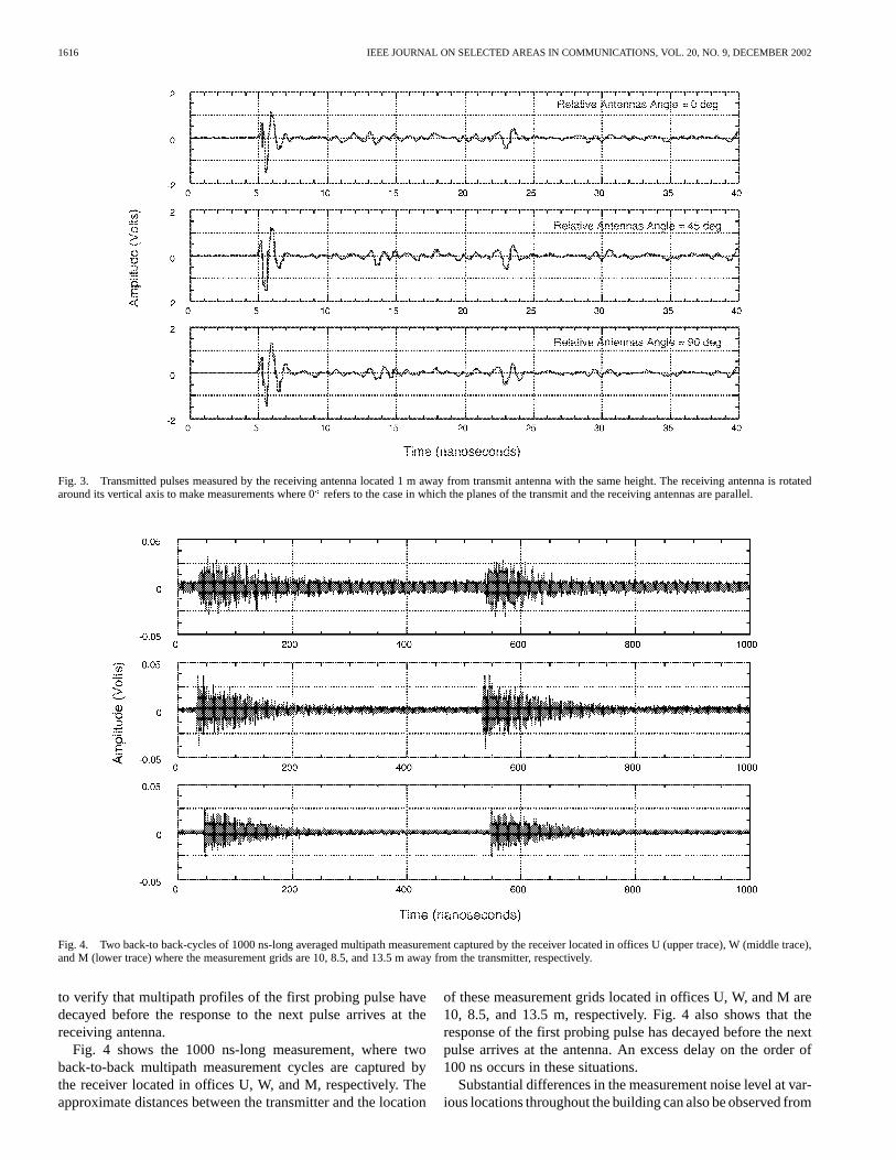
Fig. 3 shows the transmitted pulses measured by the receivingantenna, located 1 m from the transmitting antenna at the sameheight. The antennas used in this experiment were diamonddipoles [57]. Measurements were made while the vertically po-larized receiving antenna was rotated about its axis in 45steps.Measurements shown in Fig. 3 are labeled 0, 45 , and 90,where 0 refers to the case in which the planes of the transmit-ting and receiving antennas are parallel. The packaged antennas,which are flat and roughly the size of a playing card, displaynearly circularly symmetric dipole-like radiation patterns abouttheir vertical axes. The building floor plan of Fig. 2 indicatesthat the closest object to the measurement apparatus is the southwall of laboratory F, which is at least 1 m away. The signalarriving at the receiving antenna, except for the line-of-sight
(LOS) signal, must travel a minimum distance of 3 m. The ini-tial multipaths come from the floor and ceiling, 5.2 and 4.1 nsafter the LOS signal, respectively, and hence the first 10 nsof the recorded waveforms in Fig. 3 represent clean pulses ar-riving via the direct LOS path and not corrupted by multipathcomponents.
Multipath profiles are measured at various locations in therooms and hallways throughout one floor of the building.Specifically, data was collected in 14 different rooms andalong the hallways. In each room, 300 ns-long responsemeasurements are made at 49 different locations in one squareyard. The approximate location of these measurement gridsin each room is shown in Fig. 2. They are arranged spatiallyin a level 7 7 square grid with 6 inch spacing betweenmeasurement points. Each location on the grid is numberedas ( ), where represents the row index andrepresentsthe column index of the grid. As a convention, the first rowis always parallel and adjacent to the north wall of the room.The receiving antenna is located 120 cm from the floor and150 cm from the ceiling. This antenna height is envisioned tobe typical for future indoor applications. A single multipathprofile of 1000 ns duration, which captures the response of twosuccessive probing pulses, is also made in each room. This is
1616 IEEE JOURNAL ON SELECTED AREAS IN COMMUNICATIONS, VOL. 20, NO. 9, DECEMBER 2002
Fig. 3. Transmitted pulses measured by the receiving antenna located 1 m away from transmit antenna with the same height. The receiving antenna is rotatedaround its vertical axis to make measurements where 0refers to the case in which the planes of the transmit and the receiving antennas are parallel.
Fig. 4. Two back-to back-cycles of 1000 ns-long averaged multipath measurement captured by the receiver located in offices U (upper trace), W (middletrace),and M (lower trace) where the measurement grids are 10, 8.5, and 13.5 m away from the transmitter, respectively.
to verify that multipath profiles of the first probing pulse havedecayed before the response to the next pulse arrives at thereceiving antenna.
Fig. 4 shows the 1000 ns-long measurement, where twoback-to-back multipath measurement cycles are captured bythe receiver located in offices U, W, and M, respectively. Theapproximate distances between the transmitter and the location
of these measurement grids located in offices U, W, and M are10, 8.5, and 13.5 m, respectively. Fig. 4 also shows that theresponse of the first probing pulse has decayed before the nextpulse arrives at the antenna. An excess delay on the order of100 ns occurs in these situations.
Substantial differences in the measurement noise level at var-ious locations throughout the building can also be observed from

WIN AND SCHOLTZ: CHARACTERIZATION OF ULTRA-WIDE BANDWIDTH WIRELESS INDOOR COMMUNICATIONS CHANNEL 1617
Fig. 5. Averaged multipath profiles over a 40 ns window measured at (4,1), (4,4), and (4,7) of the grid denoted by F2 in building floor plan of Fig. 2. The firstarriving signal of the top trace is shadowed by the steel core support pillar located between the transmitter and the receiver.
Fig. 4. Specifically, the multipath profiles recorded in the officesW and M have a substantially lower noise level compared withthe profiles recorded in office U. This can be explained, withthe help of the building floor plan given in Fig. 2, by observingthe following. Office U is situated at the edge of the buildingwith a large glass window and is subject to more external inter-ference. Offices W and M are situated roughly in the middle ofthe building. Furthermore, office W is situated in the vicinity ofroom R and office M is adjacent to room R which is shieldedfrom electromagnetic radiation. Therefore, most of the interfer-ence from radio stations, television stations, cellular and pagingtowers and other external electromagnetic interference (EMI)sources is attenuated by the shielded walls and multiple layersof other regular walls. In general, an increased noise floor is ob-served for all the measurements made in offices located at edgesof the building with large glass windows.
Fig. 5 shows the measurements at (4,1), (4,4), and (4,7), i.e.,three different positions one foot apart along a horizontal lineof the grid, denoted by F2 in Fig. 2. Note that the receiver andtransmitter are located in the same room. It can be seen in Fig. 5that the first arriving peak of the signal level increases as the re-ceiving antenna moves from (4,1) to (4,7). This can be attributedto the shadowing by the steel core support pillar located betweenthe transmitter and the receiver as seen in the building floor planof Fig. 2.
Fig. 6 shows the 40 ns long averaged multipath profilesmeasured at the center of the measurement grid at position(4,4) in offices P, H, and B. The approximate distances betweenthe transmitter and the receiving antenna positions in offices P,H, and B are 6, 10, and 17 m, respectively, representing typicalUWB signal transmission paths for the “high signal-to-noiseratio (SNR),” “low SNR,” and “extreme low SNR” environ-ments as we have named them. Notice that the first arrivingmultipath component isnot always the strongest multipath
component. A total of 741 different multipath profile measure-ments are made at various locations (12 different rooms with49 locations/room, 2 49 locations in the lab, 21 locations inthe shield room, and 34 locations around the hallways).
D. Miscelleneous Results
To understand the effect of office doors, two multipath pro-files were recorded at the same location in office B. One profilewas recorded with the office door open and the other with theoffice door closed, however no noticeable difference betweenthese two situations was observed in this experiment.
The effect of microwave oven leakage is observable. Therewere two microwave ovens located in break room M and onelocated in supply room Q. Some multipath propagation mea-surements were made while either of the microwave ovens wasoperating. It was observed that microwave ovens significantlycorrupt the multipath profile measurements even when thereceiver is located several meters (and a few walls) away fromthe operating microwave oven.
The effect of a large computer monitor was also considered.When the receiving antenna was placed near a large computermonitor in office C, a slight increase in noise floor was observedwhen the computer monitor was turned on.
III. CHARACTERIZATION OF THE UWB PROPAGATION
CHANNEL
A statistical characterization of the propagation channel oftenis useful in communication systems engineering, e.g., in de-riving optimal reception methods, estimating the system perfor-mance, performing design tradeoffs, etc. In this section, char-acterization of the UWB propagation channel is done, basedon 741 measured multipath profiles described in Section II-C.

1618 IEEE JOURNAL ON SELECTED AREAS IN COMMUNICATIONS, VOL. 20, NO. 9, DECEMBER 2002
Fig. 6. Averaged multipath profiles over a 40 ns window measured at the center of the measurement grid in offices P (upper trace), H (middle trace), and B(lowertrace). The positions of the receiving antenna in offices P, H, and B are located 6, 10, and 17 m away from the transmitter, respectively, representing typical UWBsignal transmission for the “high SNR,” “low SNR,” and “extreme low SNR” environments.
Each measured multipath profile or received signal canbe written as
(1)
where represents the receiver noise as well as the unde-sired interference. The quantity is the channel responseto the transmitted UWB signal in the absence of undesired inter-ference and receiver noise.2 For the case of free-space propaga-tion (absence of multipath) , whereis the ideal received waveform, and models the free-spacepath loss. The parameterindexes the outcome of the stochasticenvironment , where withand .3 The stochastic environment in the context ofthis paper is a measurement experiment performed in an officebuilding, where denotes aparticular obser-vation, denotes the channel response to the trans-mitted UWB pulse at aspecificposition inside an office, and
is theobservationnoise. Since the measurementprocess of is carried out using a DSO, the measurementnoise can be modeled as additive white Gaussian noise(AWGN).
The UWB radio design problem is closely coupled to de-tails of the channel characterization. For example, in a knownchannel with AWGN and no intersymbol interference, an op-timal UWB radio should perform coherent detection of the pos-sible received data signals. Therefore, the optimum synchronousreceiver is a matched filter or correlation receiver [60] in whichcorrelator reference signals are constructed from copies of the
2The UWB signalss(u ; t) in this experiment occupy a wide bandwidthcentered around 1 GHz. The recent ruling [58] by the United States FederalCommunications Commission restricts UWB communication activity to the fre-quency band between 3.1 and 10.6 GHz. This difference in band occupancyshould be considered in using the results contained herein.
3The product space can be defined rigorously [59].
noise-free pulse-response function of the channel in thesame way that the transmitted modulation is constructed fromcopies of the transmitted pulse .
For a specific observation in the presence of mul-tipath, the question of channel characterization from a Rake re-ceiver design viewpoint is how well one can match the signal
with a template consisting of a linear combina-tion of delayed versions of a synthesizable waveform . Notethat fundamental building block of a UWB receiver ide-ally should resemble the shape of waveforms received over asingle propagation path.4 Specifically, the template waveformbuilt into the receiver for use in Rake correlator structures ismodeled as [63], [64]
(2)
The parameters and are modeled as random vari-ables with and .5
Characterizations of the propagation channel can be sepa-rated into two categories, namely (A) non model-based charac-terizations and (B) model-based characterizations. Both of theseapproaches will be considered in the following sections.
A. Non Model-Based Multipath Channel Characterization
As the name implies, non model-based channel characteriza-tion is carried outwithout using a specific modelfor the mul-tipath channel. There are no models used or assumptions madeabout the structure of the signal (such as (2) that resultedfrom specular multipath propagation).
4Even under ideal free-space propagation conditions, the received waveformmay not look like the waveform driving the transmitting antenna. For examplesof such transmission effects, see [61], [62].
5The usual notation for = (�1;+1) and = [0;+1) is used.
WIN AND SCHOLTZ: CHARACTERIZATION OF ULTRA-WIDE BANDWIDTH WIRELESS INDOOR COMMUNICATIONS CHANNEL 1619
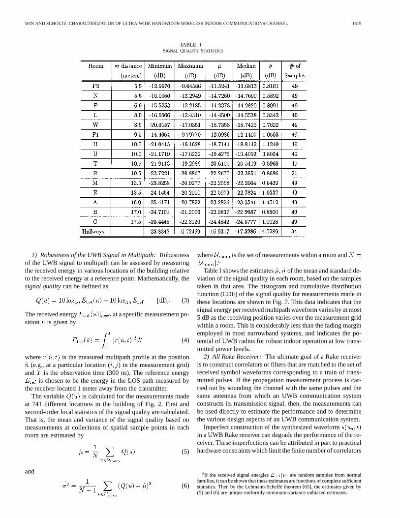
TABLE ISIGNAL QUALITY STATISTICS
1) Robustness of the UWB Signal in Multipath:Robustnessof the UWB signal to multipath can be assessed by measuringthe received energy in various locations of the building relativeto the received energy at a reference point. Mathematically, thesignal qualitycan be defined as
(3)
The received energy at a specific measurement po-sition is given by
(4)
where is the measured multipath profile at the position(e.g., at a particular location ( ) in the measurement grid)
and is the observation time (300 ns). The reference energyis chosen to be the energy in the LOS path measured by
the receiver located 1 meter away from the transmitter.The variable is calculated for the measurements made
at 741 different locations in the building of Fig. 2. First andsecond-order local statistics of the signal quality are calculated.That is, the mean and variance of the signal quality based onmeasurements at collections of spatial sample points in eachroom are estimated by
(5)
and
(6)
where is the set of measurements within a room and.6
Table I shows the estimates, of the mean and standard de-viation of the signal quality in each room, based on the samplestaken in that area. The histogram and cumulative distributionfunction (CDF) of the signal quality for measurements made inthese locations are shown in Fig. 7. This data indicates that thesignal energy per received multipath waveform varies by at most5 dB as the receiving position varies over the measurement gridwithin a room. This is considerably less than the fading marginemployed in most narrowband systems, and indicates the po-tential of UWB radios for robust indoor operation at low trans-mitted power levels.
2) All Rake Receiver:The ultimate goal of a Rake receiveris to construct correlators or filters that are matched to the set ofreceived symbol waveforms corresponding to a train of trans-mitted pulses. If the propagation measurement process is car-ried out by sounding the channel with the same pulses and thesame antennas from which an UWB communication systemconstructs its transmission signal, then, the measurements canbe used directly to estimate the performance and to determinethe various design aspects of an UWB communication system.
Imperfect construction of the synthesized waveformin a UWB Rake receiver can degrade the performance of the re-ceiver. These imperfections can be attributed in part to practicalhardware constraints which limit the finite number of correlators
6If the received signal energiesE (u) are random samples from normalfamilies, it can be shown that these estimates are functions of complete sufficientstatistics. Then by the Lehmann-Scheffé theorem [65], the estimates given by(5) and (6) are unique uniformly minimum-variance unbiased estimates.

1620 IEEE JOURNAL ON SELECTED AREAS IN COMMUNICATIONS, VOL. 20, NO. 9, DECEMBER 2002
Fig. 7. The histogram (upper plot) and cumulative distribution function (lower plot) of the signal quality based on 49 spatial sample points (except 21 spatialpoints for room R and 34 spatial points for hallways) in each room. A total of 741 measurements are used in these plots.
available in a Rake receiver architecture.7 The degradation dueto the multipath channel can be separated from the effect ofimperfect construction of the synthesized waveform by con-sidering theall Rake (ARake) receiver. The ARake receiveris a Rake receiver with unlimited resources (correlators) andinstant adaptability, so that it can, in principle, perfectly con-struct matched filters or correlator reference signals that areidentical to the set of received symbol waveforms. Although this
7This issue is closely related to the design of “selective Rake” receiver archi-tectures [66]–[72] and is addressed in the next section.
is not practical, an ARake receiver serves as the best case (benchmark) for Rake receiver design.
The performance of any ideal synchronous receiver operatingover a single-link AWGN channel depends on the autocorre-lation matrix of the signal set. When the multipath spread ismuch less than the pulse spacing during transmission, the effectof intersymbol and interpulse interference is negligible and,hence, this autocorrelation matrix and an appropriately definedSNR are the only quantities determining the performance of anoptimal receiver. Hence, the performance of such a perfectlysynchronized UWB ARake receiver in a multipath environment

WIN AND SCHOLTZ: CHARACTERIZATION OF ULTRA-WIDE BANDWIDTH WIRELESS INDOOR COMMUNICATIONS CHANNEL 1621
Fig. 8. Joint normalized plot of 49 differentR (�) functions obtained in room P. The transmitter is approximately 6 m from the receiver representing typicalUWB signal transmission for the “high SNR” environment.
can be predicted by computing the autocorrelation functionof a noise-free channel response
(7)
and appropriately sampling this function to construct the auto-correlation matrix of the signal set used by the UWB radio [73].In an ideal channel (in the absence of multipath), the correlationfunction is given by
(8)
where is the sounding signal seen at the receiving antennaoutput in the absence of multipath. As pointed in Section II-C,measurements made in the offices located in the interior partof the building have a lower noise floor. Furthermore, aver-aging the multipath profiles that are sequentially collected at afixed location effectively suppresses the observation noise. Inthis case . Then, becomes
(9)
The function is computed for each of the 741 dif-ferent measurement locations using the approximation (9). Itslocal variation can be assessed by jointly displaying the normal-ized plot of different functions for the 49 measure-ment points in each room. Fig. 8 shows the normalized plotsof different functions in room P. This illustrates atypical ensemble of autocorrelation functions that must be con-sidered in choosing a data modulation technique. As one wouldexpect, when normalized to equal energy these correlation func-tions look approximately the same for values of the shift param-eter less than a transmitted pulse width (1 ns). However,these correlation functions vary considerably for larger valuesof because the set of differential path delays varies for dif-
ferent points on the measurement grid. This implies that the au-tocorrelation matrix of the signal set used by the UWB radio isa random matrix with entries consisting of various samples ofthe correlation function.
For values of larger than the transmitted pulse width, theseplots of may look quite different for different rooms.For the pulse used to sound rooms and produce the curves ofFig. 8, a reasonable amount of time shift for 2-level pulse po-sition modulation (PPM) is the location of the first aggregateminimum next to the peak in these curves, i.e., roughly 0.5 ns.Notice that the performance prediction [for example, bit-errorprobability (BEP)] will vary somewhat from position to positionwithin the measurement grid since the autocorrelation matrix ofthe signal set is a random matrix with varying entries from po-sition to position. This technique of using measured multipathprofiles to evaluate signal designs has been used to compare theBEP performance of different possible 4-ary PPM designs [74].
B. Model-Based Multipath Channel Characterization
Channel characterization for Rake receiver design can becarried out using aa finite specular-multipath channel model
given in (2) for the signal . This model isused by the receiver in its construction of the Rake signalprocessor with fundamental building block waveform .The actual environment that creates the multipath signal maynot realistically be viewed as containing only reflectors and,hence, the model cannot perfectly represent .
In general, the number of resolvable path components in a re-alistic dense multipath channel (especially in an indoor channel)is roughly proportional to the transmission bandwidthandthe excess delay of the channel. While the product maybe large for a UWB signal transmission, only a small fraction ofthese resolvable multipath components may be necessary in thereceiver’s signal model to ensure the utilization of a reasonablefraction of the energy available in a received symbol waveform.
1) A Specular Multipath Channel Model:An efficient Rakereceiver using a specified number of correlators,, is based on
1622 IEEE JOURNAL ON SELECTED AREAS IN COMMUNICATIONS, VOL. 20, NO. 9, DECEMBER 2002
Fig. 9. A typical idealized received waveform as a function oftime in nanoseconds. The model used in this plot isw(t + :35) =[1 � 4�(t=� ) ] exp[�2�(t=� ) ] with � = 0:2877, which is assumedto be reasonably well matched to the isolated paths in the whole ensemble ofmeasured received waveforms.
a specular -path model for the channel that best matches thewaveform . The number is proportional to the com-plexity of receiver’s demodulator. In the existing literature, thisis typically accomplished by discretizing the delay axis into binsof width seconds. If the integrated power, within the in-terval of delay bin, of the received signal exceeds thechosen minimum detectable signal threshold, a multipath com-ponent with magnitude is said to exist at delay . The
paths corresponding to the largest values ofmay then bechosen as the dominant paths [28].
The number of multipath components also influences thechoice of channel modeling techniques. If the number of mul-tipath components is small ( 5), then, they can be attributedto obvious reflecting objects in the radio system environment,and a ray tracing model based on the building geometry is aplausible choice. On the other hand, ray tracing techniquesbecomes site specific and their computational complexitybecomes a burden when the number of multipath componentsis large [28].
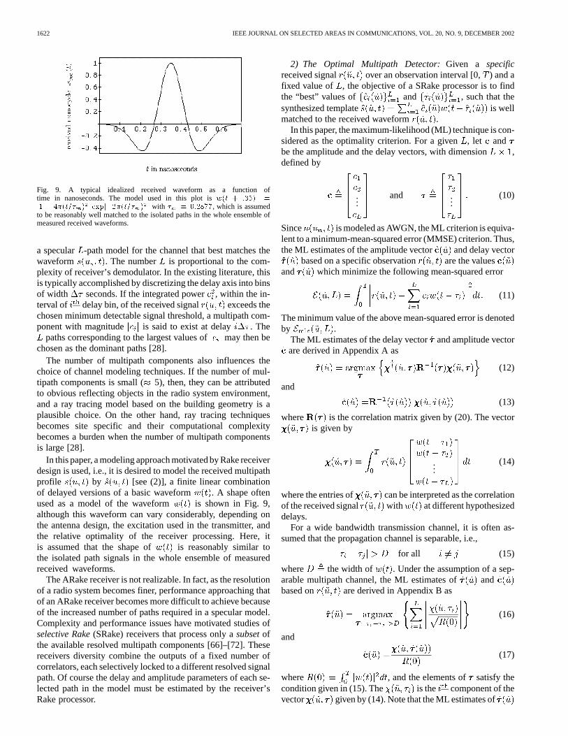
In this paper, a modeling approach motivated by Rake receiverdesign is used, i.e., it is desired to model the received multipathprofile by [see (2)], a finite linear combinationof delayed versions of a basic waveform . A shape oftenused as a model of the waveform is shown in Fig. 9,although this waveform can vary considerably, depending onthe antenna design, the excitation used in the transmitter, andthe relative optimality of the receiver processing. Here, itis assumed that the shape of is reasonably similar tothe isolated path signals in the whole ensemble of measuredreceived waveforms.
The ARake receiver is not realizable. In fact, as the resolutionof a radio system becomes finer, performance approaching thatof an ARake receiver becomes more difficult to achieve becauseof the increased number of paths required in a specular model.Complexity and performance issues have motivated studies ofselective Rake(SRake) receivers that process only asubsetofthe available resolved multipath components [66]–[72]. Thesereceivers diversity combine the outputs of a fixed number ofcorrelators, each selectively locked to a different resolved signalpath. Of course the delay and amplitude parameters of each se-lected path in the model must be estimated by the receiver’sRake processor.
2) The Optimal Multipath Detector:Given a specificreceived signal over an observation interval [0,) and afixed value of , the objective of a SRake processor is to findthe “best” values of and , such that thesynthesized template is wellmatched to the received waveform .
In this paper, the maximum-likelihood (ML) technique is con-sidered as the optimality criterion. For a given, let andbe the amplitude and the delay vectors, with dimension ,defined by
...and ...
(10)
Since is modeled as AWGN, the ML criterion is equiva-lent to a minimum-mean-squared error (MMSE) criterion. Thus,the ML estimates of the amplitude vector and delay vector
based on a specific observation are the valuesand which minimize the following mean-squared error
(11)
The minimum value of the above mean-squared error is denotedby .
The ML estimates of the delay vectorand amplitude vectorare derived in Appendix A as
(12)
and
(13)
where is the correlation matrix given by (20). The vectoris given by
...(14)
where the entries of can be interpreted as the correlationof the received signal with at different hypothesizeddelays.
For a wide bandwidth transmission channel, it is often as-sumed that the propagation channel is separable, i.e.,
for all (15)
where the width of . Under the assumption of a sep-arable multipath channel, the ML estimates of andbased on are derived in Appendix B as
(16)
and
(17)
where , and the elements of satisfy thecondition given in (15). The is the component of thevector given by (14). Note that the ML estimates of

WIN AND SCHOLTZ: CHARACTERIZATION OF ULTRA-WIDE BANDWIDTH WIRELESS INDOOR COMMUNICATIONS CHANNEL 1623
Fig. 10. The number of single-path signal correlators in a UWB Rake receiveras a function of percentage energy capture for received waveforms in an office P(upper plot) and H (lower plot) representing typical “high SNR” and “low SNR”environment. In each plot, 49 measurement waveforms are used.
and result in decoupled solutions under the assumption ofa separable multipath channel.
3) Performance Measure and Results of the ML MultipathDetector: The performance of the multipath detector can bemeasured in terms of the quantityenergy capture. Energy cap-ture as a function of for each observation is definedmathematically as
(18)
where is the total energy in the received waveformgiven by (4). Equation (18) can be interpreted as the
fraction of the received waveform energy captured by the UWBSRake receiver consisting ofsingle-path signal correlators.
Energy capture as a function of the number of single-pathsignal correlators is computed for each received waveformmeasurement. This can be used to estimate the performance of aselective Rake receiver with coherent diversity combining ofcorrelator outputs, each correlator matched to a basic buildingblock waveform . The number of required correlatorsin a UWB SRake receiver versus percentage energy captureis plotted in Fig. 10, based on the ML estimators given in(16) and (17), for each of the measured channels in offices
P and H representing a typical “high SNR” and “low SNR”environment.8 In generating this figure, we have used asthe average LOS component extracted from the “clean” pulsemeasurements in Fig. 3. Recall from Section II-C that the first10 ns of the recorded waveforms in Fig. 3 represent a cleanpulse arriving via the direct LOS path and are not corrupted bymultipath components.
Note in Fig. 10 that the amount of captured energy increasesrapidly as the number of correlators increases from 0 to 50.However, this improvement becomes gradual as the number ofcorrelators increases from 50 to 100. Beyond this point, onlya negligible improvement in energy capture can be made. Be-cause of complexity constraints in practice, UWB SRake re-ceivers are designed to operate in the regions where the increasein energy capture as a function of the number of correlators israpid. Fig. 10 also suggests that the number of dominant spec-ular multipath components is expected to be less than 50 forUWB signal transmissions in a typical modern office building.On the other hand, the number of dominant specular multipathcomponents is much larger than five.
While the multipath model which motivates the model-basedcharacterization in Section III-B may be questioned, the signalstrengths identified by correlation with are based on actualmeasurements. These can be used to predict the performance ofa simple binary PPM with the same transmitted pulse shape, run-ning over the same measured channel, and using a correlation re-ceiver with the template waveform . The curves in Fig. 11indicate the projected BEP performance of such UWB SRakereceiver as a function of SNR and the number of single-pathsignal correlators implemented (i.e., “paths” tracked). It is as-sumed that the receiver chooses the delays and amplitudes tooptimize performance using (16) and (17). That is, the UWBPPM SRake receiver with the pictured performance implementsa maximum-energy-capture algorithm for a given numberofcorrelators. Notice that there is a somewhat wider spread be-tween the and in the low SNR case in Fig. 11,indicating that there is slightly more to be gained for large.The SNR offset between a curve in the low SNR environmentand the corresponding curve in the high SNR environment canbe determined roughly from the data of Table I or Fig. 7.
IV. CONCLUSION
The signal propagation experiment described here was per-formed in a typical modern laboratory/office building to charac-terize indoor UWB signal propagation channels. The bandwidthof the signal used in this experiment was in excess of 1 GHz,resulting in a differential path delay resolution of less than ananosecond without special processing. Robustness of the UWBsignal to fades is quantified through histograms and cumula-tive distributions of the signal quality in various locations ofthe building. The results demonstrate that a UWB signal in thisenvironment does not suffer deep fades and that UWB radios
8The “usual” separable channel assumptions given in (15) may not always bevalid, even in the case of UWB transmissions channels. However, the ML esti-mators derived under this assumption are used in computations for simplicity.The optimal solution in the case of nonseparable multipath is computation in-tensive. One suboptimal approach in this case is to use the CLEAN algorithm,and an example of its application to UWB propagation channels can be foundin [36].

1624 IEEE JOURNAL ON SELECTED AREAS IN COMMUNICATIONS, VOL. 20, NO. 9, DECEMBER 2002
Fig. 11. BEP performance of selective Rake receiver in an office P (upper plot) and H (lower plot) representing typical “high SNR” and “low SNR” environment.In each plot, 49 measurement waveforms are used.
have the potential for robust indoor operation at low transmittedpower levels.
ARake receivers and SRake receivers have been discussed.The ARake receiver serves as the best case (bench mark) for aRake receiver design and lower bounds the performance degra-dation caused by multipath. Typical ensembles of ARake auto-correlation functions suggest that multipath places some limiton the ability to extend PPM techniques to the-ary case.These results must be taken into account when designing datamodulation schemes that provide robust, simple, high-rate com-munication capability in the presence of multipath.
Multipath components of measured waveforms are deter-mined using a ML estimator which is based on a separablespecular multipath channel model. Energy capture (and,consequently, BEP for an SRake receiver using a maximum-en-ergy-capture policy) as a function of the number of single-pathsignal correlators used in an UWB SRake receiver shows thatthe number of dominant specular multipath components istypically less than 50 for UWB signal transmissions in a typicalmodern laboratory/office building. On the other hand, thenumber of dominant specular multipath components is much
larger than five, which suggests that ray tracing techniques maynot be feasible for these UWB indoor wireless communicationschannels.
The results for model-based characterization presentedin Section III-B are based on the simple template structuresuggested by the specular model given in (2). However, morecomplicated template structures are possible at the expense ofreceiver complexity. One such example is the use of a family ofbasic building block waveforms and determinationof the “best” choice of such thatthe synthesized waveform iswell matched to the received waveform .
APPENDIX
ML M ULTIPATH DETECTOR
It can be shown that the ML estimates of the amplitude vectorand delay vector are the values and thatminimize
the statistic
(19)
WIN AND SCHOLTZ: CHARACTERIZATION OF ULTRA-WIDE BANDWIDTH WIRELESS INDOOR COMMUNICATIONS CHANNEL 1625
The correlation matrix is a function of and is given by
......
.. ....
(20)with each entry of the matrix is
(21)
The vector is given by
...(22)
where the components of can be interpreted as the cor-relation of the received signal with at different hy-pothesized delays. Let
(23)
Then, adding and subtracting the quantity, and regrouping like terms, gives
(24)
Note that and are nonnegative quadratic forms within-dependent of the choice of, so that is minimized when
by choice of , and
(25)is maximized over . The condition implies that
(26)
Therefore, ML estimates of the delay vectorand amplitudevector are
(27)
and
(28)
APPENDIX
ML M ULTIPATH DETECTOR FOR ASEPARABLE CHANNEL
When the propagation channel is separable, thenfor all and the correlation matrix becomes
......
......
where . Note that is independent ofin this case and simple matrix manipulation shows that
(29)
where
(30)
Therefore, the ML estimates of and based on aspecific observation become
(31)
and
(32)
ACKNOWLEDGMENT
The authors wish to thank the Time Domain Corporation forits assistance and support for the propagation measurement ex-periments described herein.
REFERENCES
[1] G. F. Ross, “The transient analysis of certain TEM mode four-post net-works,” IEEE Trans. Microwave Theory Technol., vol. 14, p. 528, Nov.1966.
[2] C. L. Bennett and G. F. Ross, “Time-domain electromagnetics and itsapplications,”Proc. IEEE, vol. 66, pp. 299–318, Mar. 1978.
[3] M. Z. Win and R. A. Scholtz, “Impulse radio: How it works,”IEEECommun. Lett., vol. 2, pp. 36–38, Feb. 1998.
[4] , “Comparisons of analog and digital impulse radio for multiple-access communications,” inProc. IEEE Int. Conf. Communication, vol.1, June 1997, pp. 91–95.
[5] M. Z. Win, X. Qiu, R. A. Scholtz, and V. O. K. Li, “ATM-basedTH-SSMA network for multimedia PCS,”IEEE J. Select. AreasCommun., vol. 17, pp. 824–836, May 1999.
[6] M. Z. Win and R. A. Scholtz, “Ultra-wide bandwidth time-hoppingspread-spectrum impulse radio for wireless multiple-access communi-cations,”IEEE Trans. Commun., vol. 48, pp. 679–691, Apr. 2000.
[7] M. Z. Win, “A unified spectral analysis of generalized time-hoppingspread-spectrum signals in the presence of timing jitter,”IEEE J. Select.Areas Commun., vol. 20, pp. XXX–XXX, Dec. 2002, to be published.
[8] S. S. Kolenchery, J. K. Townsend, J. A. Freebersyser, and G. Bilbro,“Performance of local power control in peer-to-peer impulse radio net-works with bursty traffic,” inProc. IEEE Global TelecommunicationsConf., vol. 2, Nov. 1997, pp. 910–916.
[9] S. S. Kolenchery, J. K. Townsend, and J. A. Freebersyser, “A novel im-pulse radio network for tactical military wireless communications,” inProc. Military Communications Conf., vol. 1, Boston, MA, Oct. 1998,pp. 59–65.
[10] G. D. Weeks, J. K. Townsend, and J. A. Freebersyser, “Performance ofhard decision detection for impulse radio,” inProc. Military Communi-cations Conf., vol. 2, Atlantic City, NJ, Oct. 1999, pp. 1201–1206.
[11] J. Conroy, J. L. LoCicero, and D. R. Ucci, “Communication techniquesusing monopulse waveforms,” inProc. Military Communications Conf.,vol. 2, Atlantic City, NJ, Oct. 1999, pp. 1181–1185.
[12] H. Lee, B. Han, Y. Shin, and S. Im, “Multipath characteristics of impulseradio channels,” inProc. 50th Annu. Int. Vehicle Technology Conf., vol.3, Tokyo, Japan, 2000, pp. 2487–2491.
[13] C. J. Le Martret and G. B. Giannakis, “All-digital PAM impulse radio formultiple-access through frequency-selective multipath,” inProc. IEEEGlobal Telecommunications Conf., vol. 1, Nov. 2000, pp. 77–81.
[14] L. Zhao and A. M. Haimovich, “Interference suppression in ultra-wide-band communications,” inProc. Conf. Information Science, System, vol.2, Baltimore, MD, Mar. 2001, pp. 759–763.
1626 IEEE JOURNAL ON SELECTED AREAS IN COMMUNICATIONS, VOL. 20, NO. 9, DECEMBER 2002
[15] L. Zhao, A. M. Haimovich, and H. Grebel, “Performance of ultra-wide-band communications in the presence of interference,” inProc. IEEEInt. Conf. Communications, vol. 10, June 2001, pp. 2948–2952.
[16] L. Zhao, A. M. Haimovich, and M. Z. Win, “Capacity of ultra-widebandwidth communications over multipath channels,” inProc. IEEEInt. Symp. Advances Wireless Communications, Victoria, Canada, Sept.2002.
[17] M. Z. Win, R. A. Scholtz, and M. A. Barnes, “Ultra-wide bandwidthsignal propagation for indoor wireless communications,” inProc. IEEEInt. Conf. Communications, vol. 1, June 1997, pp. 56–60.
[18] M. Z. Win and R. A. Scholtz, “On the robustness of ultra-wide band-width signals in dense multipath environments,”IEEE Commun. Lett.,vol. 2, pp. 51–53, Feb. 1998.
[19] , “On the energy capture of ultra-wide bandwidth signals in densemultipath environments,”IEEE Commun. Lett., vol. 2, pp. 245–247,Sept. 1998.
[20] P. A. Bello, “Characterization of randomly time-variant linear channels,”IEEE Trans. Commun. Syst., vol. COM-11, pp. 360–393, Dec. 1963.
[21] W. C. Jakes, Ed.,Microwave Mobile Communications. Piscataway,NJ: IEEE Press, 1995.
[22] R. Steele and L. Hanzo,Mobile Radio Communications: Second andThird Generation Cellular and WATM Systems, 2nd ed. New York:Wiley, 1999.
[23] K. Pahlavan and A. H. Levesque,Wireless Information Networks, 1sted. New York: Wiley, 1995.
[24] T. S. Rappaport,Wireless Communications, 1st ed. Upper SaddleRiver, NJ: Prentice-Hall, 1996.
[25] R. S. Kennedy,Fading Dispersive Communication Channels, 1sted. New York: Wiley, 1969.
[26] J. D. Parsons,The Mobile Radio Propagation Channel, 1st ed. NewYork: Wiley, 1992.
[27] J. B. Andersen, T. S. Rappaport, and S. Yoshida, “Propagation mea-surements and models for wireless communications channels,”IEEECommun. Mag., vol. 33, pp. 42–49, Jan. 1995.
[28] T. S. Rappaport, S. Y. Seidel, and K. Takamizawa, “Statistical channelimpulse response models for factory an open plan building radiocommunication system design,”IEEE Trans. Commun., vol. 39, pp.794–807, May 1991.
[29] S. Y. Seidel and T. S. Rappaport, “914 MHz path loss prediction modelsfor indoor wireless communications in multifloored buildings,”IEEETrans. Antennas Propagat., vol. 40, pp. 207–217, Feb. 1992.
[30] D. M. J. Devasirvatham, “Multipath time delay jitter measured at850 MHz in the portable radio environment,”IEEE J. Select. AreasCommun., vol. SAC-5, pp. 855–861, June 1987.
[31] A. A. Saleh and R. A. Valenzuela, “A statistical model for indoor mul-tipath propagation,”IEEE J. Select. Areas Commun., vol. SAC-5, pp.128–137, Feb. 1987.
[32] R. A. Valenzuela, O. Landron, and D. L. Jacobs, “Estimating localmean signal strength of indoor multipath propagation,”IEEE Trans.Veh. Technol., vol. 46, pp. 203–212, Feb. 1997.
[33] R. J. Bultitude, S. A. Mahmoud, and W. A. Sullivan, “A comparisonof indoor radio propagation characteristics at 910 MHz and 1.75 GHz,”IEEE J. Select. Areas Commun., vol. 7, pp. 20–30, Jan. 1989.
[34] H. Hashemi, “The indoor radio propagation channel,”Proc. IEEE, vol.81, pp. 943–968, July 1993.
[35] Q. Spencer, B. Jeffs, M. Jensen, and A. Swindlehurst, “Modeling thestatistical time and angle of arrival characteristics of an indoor multipathchannel,”IEEE J. Select. Areas Commun., vol. 18, pp. 347–360, Mar.2000.
[36] R. J.-M. Cramer, R. A. Scholtz, and M. Z. Win, “An evaluation of theultra-wideband propagation channel,”IEEE Trans. Antennas Propagat.,vol. 50, pp. 561–570, May 2002.
[37] G. Turin, F. D. Clapp, T. L. Johnston, S. B. Fine, and D. Lavry, “A statis-tical model of urban multipath propagation,”IEEE Trans. Veh. Technol.,vol. VT-21, pp. 1–9, Feb. 1972.
[38] G. Turin, “Introduction to spread-spectrum antimultipath techniquesand their application to urban digital radio,”Proc. IEEE, vol. 68, pp.328–353, Mar. 1980.
[39] H. Suzuki, “A statistical model for urban radio propagation,”IEEETrans. Commun., vol. 25, pp. 673–680, July 1977.
[40] H. Hashemi, “Simulation of the urban radio propagation channel,”IEEETrans. Veh. Technol., vol. VT-28, pp. 213–225, Aug. 1979.
[41] D. C. Cox, “Delay Doppler characteristics of multipath propagation at910 MHz in a suburban mobile radio environment,”IEEE Trans. An-tennas Propagat., vol. AP-20, pp. 625–635, Sept. 1972.
[42] , “Time- and frequency-domain characterizations of multipathpropagation at 910 MHz in a suburban mobile-radio environment,”Radio Sci., pp. 1069–1077, Dec. 1972.
[43] , “910 MHz urban mobile radio propagation: Multipath charac-teristics in New York city,”IEEE Trans. Commun., vol. COM-21, pp.1188–1194, Nov. 1973.
[44] D. C. Cox and R. P. Leck, “Distributions of multipath delay spread andaverage excess delay for 910-MHz urban mobile radio paths,”IEEETrans. Antennas Propagat., vol. AP-23, pp. 206–213, Mar. 1975.
[45] D. L. Nielson, “Microwave propagation measurements for mobile digitalradio application,”IEEE Trans. Veh. Technol., vol. VT-28, pp. 117–132,Aug. 1978.
[46] V. Erceg, A. J. Rustako Jr, and R. S. Roman, “Diffraction around cornersand its effects on the microcell coverage area in urban and suburban en-vironments at 900 MHz, 2 GHz, and 6 GHz,”IEEE Trans. Veh. Technol.,vol. 43, pp. 762–766, Aug. 1994.
[47] E. S. Sousa, V. M. Jovanovic´, and C. Daigneault, “Delay spread mea-surements for the digital cellular channel in Toronto,”IEEE Trans. Veh.Technol., vol. 43, pp. 837–847, Nov. 1994.
[48] L. J. Greenstein, V. Erceg, Y. S. Yeh, and M. V. Clark, “A newpath-gain/delay-spread propagation model for digital cellular chan-nels,” IEEE Trans. Veh. Technol., vol. 46, pp. 477–485, May 1997.
[49] D. Cassioli, M. Z. Win, and A. F. Molisch, “The ultra-wide bandwidthindoor channel: From statistical model to simulations,”IEEE J. Select.Areas Commun., vol. 20, pp. 1247–1257, Aug. 2002.
[50] E. T. Whittaker, “On the functions which are represented by the exapan-sions of the interpolation theory,” inProc. Roy. Soc. Edinburgh, vol. 35,1915, pp. 181–194.
[51] J. M. Whittaker, “The Fourier theory of the cardinal functions,” inProc.Math. Soc. Edinburgh, vol. 1, 1929, pp. 169–176.
[52] R. V. L. Hartley, “The transmission of information,”Bell Syst. Tech. J.,vol. 7, pp. 535–560, 1928.
[53] H. Nyquist, “Certain topics in telegraph transmission theory,”AIEETrans., vol. 47, pp. 617–644, Apr. 1928.
[54] C. E. Shannon, “Communications in the presence of noise,”Proc. IRE,vol. 37, pp. 10–21, Jan. 1949.
[55] D. Slepian, “On bandwidth,”Proc. IEEE, vol. 64, pp. 292–300, Mar.1976.
[56] A. J. Jerri, “The Shannon sampling theorem – Its various extensions andapplications: A tutorial review,”Proc. IEEE, vol. 65, pp. 1565–1596,Nov. 1977.
[57] H. G. Schantz and L. Fullerton, “The diamond dipole: A Gaussian im-pulse antenna,” inProc. IEEE AP-S Int. Symp. USNC/URSI NationalRadio Science Meeting, vol. 4, July 2001, pp. 100–103.
[58] “Revision of Part 15 of the Commission’s Rules Regarding Ultra-Wide-band Transmission Systems,” Federal Communications Commission,ET Docket 98–153, 2002.
[59] R. Durrett,Probability: Theory and Examples, first ed. Pacific Grove,CA: Wadsworth, 1991.
[60] M. K. Simon, S. M. Hinedi, and W. C. Lindsey,Digital CommunicationTechniques: Signal Design and Detection, 1st ed. Englewood Cliffs,NJ: Prentice-Hall, 1995.
[61] R. C. Robertson and M. A. Morgan, “Ultra-wideband impulse receivingantenna design and evaluation,” inUltra-Wideband Short Pulse Electro-magnetics 2, L. Carin and L. B. Felsen, Eds. New York: Plenum, 1995,pp. 179–196.
[62] J. G. Maloney, G. S. Smith, and W. R. Scott Jr, “Accurate computa-tion of the radiation from simple antennas using the finite-differencetime-domain method,”IEEE Trans. Antennas Propagat., vol. 38, pp.1059–1068, July 2000.
[63] R. Price and P. E. Green Jr, “A communication technique for multipathchannels,”Proc. IRE, vol. 46, pp. 555–570, Mar. 1958.
[64] J. G. Proakis,Digital Communications, 4th ed. New York: McGraw-Hill, 2001.
[65] P. J. Bickel and K. Doksum,Mathematical Statistics: Basic Ideas andSelected Topics, 1st ed. Oakland, CA: Holden-Day, 1977.
[66] M. Z. Win and Z. A. Kostic, “Virtual path analysis of selective Rakereceiver in dense multipath channels,”IEEE Commun. Lett., vol. 3, pp.308–310, Nov. 1999.
[67] M. Z. Win, G. Chrisikos, and N. R. Sollenberger, “Effects of chip rate onselective Rake combining,”IEEE Commun. Lett., vol. 4, pp. 233–235,July 2000.
[68] M. Z. Win and Z. A. Kostic, “Impact of spreading bandwidth on Rakereception in dense multipath channels,”IEEE J. Select. Areas Commun.,vol. 17, pp. 1794–1806, Oct. 1999.
[69] M. Z. Win, G. Chrisikos, and N. R. Sollenberger, “Performance of Rakereception in dense multipath channels: Implications of spreading band-width and selection diversity order,”IEEE J. Select. Areas Commun.,vol. 18, pp. 1516–1525, Aug. 2000.
[70] M. Z. Win and G. Chrisikos, “Impact of spreading bandwidth and selec-tion diversity order on selective Rake reception,” inWideband WirelessDigital Communications, A. F. Molisch, Ed. Upper Saddle River, NJ:Prentice-Hall, 2001, pp. 424–454.

WIN AND SCHOLTZ: CHARACTERIZATION OF ULTRA-WIDE BANDWIDTH WIRELESS INDOOR COMMUNICATIONS CHANNEL 1627
[71] M. Z. Win, G. Chrisikos, A. F. Molisch, and N. R. Sollenberger, “Se-lective Rake diversity in multipath fading with arbitrary power delayprofile,” in Proc. IEEE Global Telecommunications Conf., vol. 2, Dec.2000, pp. 960–964.
[72] D. Cassioli, M. Z. Win, F. Vatalaro, and A. F. Molisch, “Performance ofselective Rake reception in a realistic UWB channel,” inProc. IEEE Int.Conf. Commununications, vol. 2, May 2002, pp. 763–767.
[73] C. L. Weber,Elements of Detection and Signal Design, 1st ed. NewYork: Springer-Verlag, 1987.
[74] F. Ramírez-Mireles, M. Z. Win, and R. A. Scholtz, “Signal selectionfor the indoor wireless impulse radio channel,” inProc. 47th Annu. Int.Vehicular Technology Conf., Phoenix, AZ, May 1997, pp. 2243–2247.
Moe Z. Win (S’85–M’87–SM’97) received theB.S. degree (magna cum laude) from Texas A&MUniversity, College Station, and the M.S. degreefrom the University of Southern California (USC),Los Angeles, in 1987 and 1989, respectively, inelectrical engineering. As a Presidential Fellow atUSC, he received both an M.S. degree in appliedmathematics and the Ph.D. degree in electricalengineering in 1998. He is a Distinguished Alumnusof Mountain View College.
In 1987, he joined the Jet Propulsion Laboratory(JPL), California Institute of Technology, Pasadena, where he performed re-search on digital communications and optical systems for NASA space explo-ration missions. From 1994 to 1997, he was a Research Assistant with the Com-munication Sciences Institute at USC, where he played a key role in the suc-cessful creation of the Ultra-Wideband Radio Laboratory. From 1998 to 2002,he was with the Wireless Systems Research Department, AT&T Laboratories-Research, Middletown, NJ. During that time, he performed research on severalaspects of high-data-rate multiple-access systems and made fundamental contri-butions to communication theory and its application to wideband wireless trans-mission. In 2000, he was promoted to a Principal Technical Staff Member. Since2002, he has been with the Laboratory for Information and Decision Systems(LIDS), Massachusetts Institute of Technology, Cambridge, where he holds theCharles Stark Draper Chair. His main research interests are the application ofcommunication, detection, and estimation theories to a variety of communica-tions problems including time-varying channels, diversity, equalization, syn-chronization, signal design, ultrawide-bandwidth communication, and opticalcommunications.
Dr. Win has been involved actively in organizing and chairing sessions andhas served as a Member of the Technical Program Committee in a number ofinternational conferences. He currently serves as the Technical Program Chairfor the IEEE Communication Theory Symposium of ICC-2004. He served asthe Technical Program Chair for the IEEE Communication Theory Symposiumof Globecom-2000 and the IEEE Conference on Ultra-Wideband Systems andTechnologies (2002), Technical Program Vice-Chair for the IEEE InternationalConference on Communications (2002), and the Tutorial Chair for the IEEESemiannual International Vehicular Technology Conference (Fall-2001). Heis the secretary for the Radio Communications Technical Committee, thecurrent Editor forEqualization and Diversityfor the IEEE TRANSACTIONS
ON COMMUNICATIONS and a Guest Editor for the 2002 IEEE JOURNAL ON
SELECTED AREAS IN COMMUNICATIONS, Special Issue on Ultra-WidebandRadio in Multiaccess Wireless Communications. He is a member of Eta KappaNu, Tau Beta Pi, Pi Mu Epsilon, Phi Theta Kappa, and Phi Kappa Phi. Hewas a University Undergraduate Fellow at Texas A&M University, where hereceived, among others awards, the Academic Excellence Award. At USC, hereceived several awards including the Outstanding Research Paper Award andthe Phi Kappa Phi Student Recognition Award. He was the recipient of theIEEE Communications Society Best Student Paper Award at the Fourth AnnualIEEE NetWorld+Interop ’97 Conference.
Robert A. Scholtz (S’56–M’59–SM’73–F’80–LF’02) was born in Lebanon, OH, on January 26,1936. He is a Distinguished Alumnus of the Univer-sity of Cincinnati, where, as a Sheffield Scholar, hereceived the E.E. degree in 1958. He was a HughesMasters and Doctoral Fellow while obtaining theM.S. and Ph.D. degrees in electrical engineeringfrom University of Southern California (USC), LosAngeles, in 1960, and Stanford University in 1964,respectively.
While working on missile radar signal processingproblems, he remained part-time at Hughes Aircraft Company until 1978. In1963, he joined the faculty of the University of Southern California, wherehe is now Professor of Electrical Engineering. From 1984 to 1989, he servedas Director of USC’s Communication Sciences Institute. He was Chairman ofthe Electrical Engineering Systems Department from 1994 to 2000. In 1996,as part of the Integrated Media Systems Center effort, he was instrumental informing the Ultra-wideband Radio Laboratory (UltRa Lab) to provide facili-ties for the design and test of impulse radio systems and other novel high-band-width high-data-rate wireless mobile communication links. He has consulted forthe LinCom Corporation, Axiomatix, Inc., the Jet Propulsion Laboratory, Tech-nology Group, TRW, Pulson Communications (Time Domain Corporation), andQualcomm, as well as various government agencies. His research interests in-clude communication theory, synchronization, signal design, coding, adaptiveprocessing, and pseudonoise generation, and their application to communica-tions and radar systems. He has co-authoredSpread Spectrum Communicationswith M. K. Simon, J. K. Omura, and B. K. Levitt, andBasic Concepts in In-formation Theory and Codingwith S. W. Golomb and R. E. Peile. He has beenGeneral Chairman of five workshops in the area of communications, includingmost recently the Ultrawideband Radio Workshop held in May 1998, and hasbeen an active participant on NSF panels and in research planning workshopsof the U.S. Army Research Office.
Dr. Scholtz was elected to the grade of Fellow in the IEEE, “for contribu-tions to the theory and design of synchronizable codes for communications andradar systems” in 1980. In 1983, he received the Leonard G. Abraham PrizePaper Award for the historical article, “The Origins of Spread Spectrum Com-munications;” this same paper received the 1984 Donald G. Fink Prize Awardgiven by the IEEE. His paper “Acquisition of Spread-Spectrum Signals by anAdaptive Array” with D. M. Dlugos received the 1992 Senior Award of theIEEE Signal Processing Society. His paper “Strategies for minimizing the in-tercept time in a mobile communication network with directive/adaptive an-tennas,” with J.-H. Oh received the Ellersick Award for the best unclassifiedpaper at Milcom 1997. His paper “ATM Based Ultrawide Bandwidth (UWB)Multiple-Access Radio Network for Multimedia PCS” with students M. Z. Win,J. H. Ju, X. Qiu, and colleague V. O. K. Li received the best student paper awardfrom the NetWorld+Interop’97 program committee. In 2001, he received theMilitary Communications Conference Award for Technical Achievement. Hehas been an active member of the IEEE for many years, manning important or-ganizational posts, including Finance Chairman for the 1977 National Telecom-munications Conference, Program Chairman for the 1981 International Sympo-sium on Information Theory, and IEEE Board of Governors positions for theIEEE Information Theory Group and the Communications Society.


