Embed Size (px)
Citation preview

CHARACTERIZATION OF ULTRA HIGH MOLECULAR WEIGHT POLYETHYLENE
(UHMWPE) MODIFIED BY METAL-GAS HYBRID ION IMPLANTATION TECHNIQUE
A Thesis Submitted to the Graduate School of Engineering and Sciences of �zmir Institute of Technology in Partial Fulfillment of
the Requirements for the Degree of
MASTER OF SCIENCE
in Materials Science
by
�adiye Emel SOKULLU URKAÇ
December 2006 �ZM�R

ii
We approve the thesis of �adiye Emel SOKULLU URKAÇ Date of Signature ………………………… 14 December 2006 Assoc. Prof. Dr. Funda TIHMINLIO�LU Supervisor Department of Chemical Engineering �zmir Institute of Technology
………………………… 14 December 2006 Prof. Dr. Ahmet ÖZTARHAN Co-Supervisor Department of Bioengineering Ege University
………………………… 14 December 2006 Assoc. Prof. Dr. Metin TANO�LU Department of Mechanical Engineering �zmir Institute of Technology
………………………… 14 December 2006 Prof. Dr. Orhan ÖZTÜRK Department of Physics �zmir Institute of Technology ………………………… 14 December 2006 Prof. Dr. Saim SELV� Department of Physics Ege University
………………………… 14 December 2006 Prof. Dr. Muhsin Ç�FTÇ�O�LU Head of Materials Science & Engineering Department �zmir Institute of Technology
………………………… Assoc. Prof. Dr. Barı� ÖZERDEM
Head of the Graduate School

iii
ACKNOWLEDGEMENTS
I would like to recognize Assoc. Prof. Funda Tıhmınlıo�lu for constant
insightful advice and guidance. She has always been a great source of stability and
encouragement, and I appreciate the efforts that she has made in my personal
development as a researcher and the numerous technical discussions required by this
study.
I am grateful to Prof. Ahmet Öztarhan for introducing me to this exciting field of
research and his fruitful collaboration and for geneourusly offering so much of his time
and knowledge to my academic development. He will always be a model for my
academic life.
I also would like to thank Prof. Efim Oks and his team in Institute of High
Current Electronics, Tomsk for providing me ion implantation of the materials.
Special thanks to Prof. Daryush Ila from Alabama A&M University, and his
team from Center for Irradiation of Materials for providing me the opportunity to use
the facilities and for their great affection and support that makes me realize my
potential.
Last but not least, I want to thank to my love Yusuf and my dearest and smallest
Atilla whose love and support has been the most important factor for my achievement.
How little is my gratitude in comparison to their contributions.

iv
ABSTRACT
CHARACTERIZATION OF ULTRA HIGH MOLECULAR WEIGHT
POLYETHYLENE (UHMWPE) MODIFIED BY METAL-GAS HYBRID
ION IMPLANTATION TECHNIQUE
The aim of this work was the characterization of the surface modified Ultra High
Molecular Weight Polyethylene (UHMWPE) in order to understand the effect of ion
implantation technique on the properties of this material. The samples were Ag and
Ag+N hybrid ion implanted by using MEVVA (Metal Vapour Vacuum Arc) ion
implantation technique with a fluence of 10 17 ions/cm2, extraction voltage of 30 kV.
Untreated and surface treated samples were investigated by Stopping and Range
of Ions into Matters (SRIM), Rutherford Back Scattered Analysis (RBS), Attenuated
Total Reflection - Fourier Transform Infrared (ATR/FT-IR) Spectroscopy, Raman
Spectroscopy, Optical Absorption Photospectroscopy (OAP), Thermo Gravimetry
Analysis (TGA), Differential Scanning Calorimetry (DSC), X-Ray Diffraction (XRD)
Analysis, Atomic Force Microscopy (AFM), Scanning Electron Microscopy (SEM),
Optical Microscopy (OM), Micro-hardness and Contact Angle Measurement.
The results of RBS analysis show that Ag ions were detected up to 32 +15 nm
after Ag implantation, and 42 +15 nm after Ag+N implantation., underneath the
surface. ATR- FTIR chemical characterization analyses results indicated that the effect
of implantation on UHMWPE surfaces caused dehydrogenation of polymer with an
increase of C=C bond formation which results in enriching the crosslinking carbon
atoms on the surface. Optical Absorption Photospectroscopy and Raman spectrum
suggests that the chemical structure of UHMWPE has changed after implantation.
The characterization results showed that the ion bombardment induced an
increase in the % crystallinity, onset and termination degradation temperatures of
UHMWPE obtained by thermal analyses, an increase in hardness, and surface
wettability and a decrease in roughness of the polymer. The surface topography results
can be attributed to the implantation inducing surface roughness decreasing due to the
better wettability properties of surfaces obtained after implantation.
In conclusion, this study has shown that ion implantation represents a powerful
tool on modifying key properties on UHMWPE surfaces.

v
ÖZET
METAL GAZ H�BR�T �YON �MPLANTASYON TEKN���YLE
MOD�F�YE ED�LM�� YÜKSEK ATOM�K KÜTLEL� POL�ET�LEN�N
KARAKTER�ZASYONU
Bu çalı�ma MEVVA iyon kayna�ı ile üretilmi� metal gaz hibrit iyon
implantasyonu yöntemiyle Yüksek Atomik Kütleli Polietilen malzemenin özelliklerinin
iyile�tirilmesine yönelik yapılan i�lem öncesi ve sonrası malzemenin karakterizasyon
çalı�masının sonuçlarını incelemektedir. Yüksek Atomik Kütleli Polietilen üzerine, Ag
ve Ag+N iyonlarıyla MEVVA tekni�i kullanılarak hibrit iyon implantasyon yapılmı�tır.
�yonlar, 30kV voltajla hızlandırılmı�tır ve 1017 ion/cm2 akıyla gönderilmi�tir.
�mplantasyon yapılmı� malzemelerde iyon konsantrasyonu da�ılımı, SRIM ve
Geri Saçılma Spektrometresi (RBS) yöntemleriyle analiz edilmi�tir. ��lem görmü� ve
görmemi� numuneler, Fourier Dönü�ümlü Kızılötesi (FT-IR) Spektroskopi, Raman
Spektroskopi, Optik Fotospektroskopi (OAP), Termal Gravimetrik Analiz (TGA),
Diferansiyel Taramalı Kalorimetri (DSC), X-I�ını Kırılması Analizi (XRD), Atomik
Güç Mikroskobu (AFM), Taramalı Elektron Mikroskobu (SEM), Optik Mikroskop
(OM), Shore-D cihazı ve Gonyometre cihazlarıyla karakterize edilmi�tir.
RBS analizinin sonuçları, Ag iyonlarının, Ag implante edilmi� örnekte,
yüzeyden 32 +15 nm., Ag+N implante edilmi� örnekte ise yüzeyden 42 +15 nm.
derinlikte oldu�unu göstermektedir. ATR-FTIR analiz sonuçları, Yüksek Atomik
Kütleli Polietilen yüzeyinde implantasyon sonucu dehidrojenasyon olu�tu�unu ve
karbon atomları arasında gerçekle�en çapraz ba�lanmalar neticesinde C=C ba�
olu�umunun arttı�ını göstermektedir. OAP ve Raman spektrum sonuçları, kimyasal
yapının implantasyon sonrası de�i�ti�ine i�aret etmektedir.
Termal karakterizasyon ı�ı�ında, kristallik yüzdesi, bozunmanın ba�lama &
sonlanma noktaları ve sertlik ölçümleri ı�ı�ında, sertlik de�erlerinde artı�
gözlenmektedir. Yüzey topografisi incelemesi sonucu, implantasyon sonrası
pürüzsüzlü�ün arttı�ı ve buna ba�lı olarak ıslaklık de�erlerinin geli�ti�i gözlenmektedir.
Sonuç olarak çalı�ma, Ag ve Ag+N hibrit iyon implantasyonunun, Yüksek
Atomik Kütleli Polietilen malzemeye ba�arıyla uygulanabilece�ini ve elde edilen
sonucun anahtar özellikler üzerinde etkili oldu�unu göstermektedir.

vi
TABLE OF CONTENTS
LIST OF FIGURES ......................................................................................................... ix
LIST OF TABLES........................................................................................................... xi
LIST OF ABBREVIATIONS......................................................................................... xii
CHAPTER 1. INTRODUCTION .................................................................................. 1
CHAPTER 2. ARTIFICIAL HIP JOINTS..................................................................... 3
2.1. Anatomy of Hip Joints......................................................................... 3
2.2. Ultra High Molecular Weight Poly Ethylene ...................................... 5
2.3. Wear .................................................................................................... 9
CHAPTER 3. ION IMPLANTATION OF POLYMERS............................................. 14
3.1. Principle of Technique....................................................................... 14
3.2 Ion Implantation Methods ................................................................... 17
3.2.1. Mass Analyzed Ion Implantation ................................................. 17
3.2.2. Direct Ion Implantation ................................................................ 19
3.2.3. Plasma Source Ion Implantation .................................................. 20
3.3. Ion Implantation Species ................................................................... 21
3.3.1. Nitrogen Ion Implantation............................................................ 21
3.3.2. Metal Ion Implantation................................................................. 22
3.4. Ion Implantation of UHMWPE.......................................................... 26
CHAPTER 4. EXPERIMENTAL ................................................................................ 31
4.1. Material and Method.......................................................................... 31
4.1.1. Material ........................................................................................ 31
4.1.2. Method ......................................................................................... 31
4.2. Characterization and properties ......................................................... 33
4.2.1. Ion Penetration Depth Analysis.................................................... 33
4.2.1.1. Stopping and Range of Ions into Matters (SRIM) .............. 33
4.2.1.2. Rutherford Back Scattered Analysis (RBS) ........................ 33
4.2.2. Chemical Characterization .......................................................... 35
vii
4.2.2.1. Optical Absorption Photospectroscopy (OAP).................... 35
4.2.2.2. Athenuated Total Reflectance / Fourier Transform
Infra Red (ATR/FT-IR) ....................................................... 35
4.2.2.3. Raman Spectroscopy .......................................................... 35
4.2.3. Thermal Analysis ......................................................................... 36
4.2.3.1. Thermo Gravimetric Analysis (TGA) and Differential
Scanning Calorimetry (DSC)............................................... 36
4.2.3.2. X-Ray Diffraction (XRD).................................................... 37
4.2.4. Surface Properties and Morphology............................................. 37
4.2.4.1. Scanning Electron Microscopy (SEM) ............................... 38
4.2.4.2. Optical Microscopy (OM) ................................................... 38
4.2.4.3. Hardness .............................................................................. 38
4.2.4.4. Wettability .......................................................................... 38
4.2.4.5. Atomic Force Microscopy (AFM)....................................... 39
CHAPTER 5. RESULTS AND DISCUSSION ........................................................... 40
5.1. Ion Penetration Depth Analysis ......................................................... 40
5.1.1. Stopping and Range of Ions into Matters (SRIM) ...................... 40
5.1.2. Rutherford Back Scattering (RBS) Analysis................................ 42
5.2. Chemical Characterization ................................................................ 44
5.2.1. Optical Absorption Photospectroscopy........................................ 44
5.2.2. Athenuated Total Reflectance / Fourier Transform Infra Red
(FT-IR) ......................................................................................... 45
5.2.3. Raman Spectroscopy ................................................................... 50
5.3. Thermal Characterization .................................................................. 55
5.3.1. Thermo Gravimetric Analysis (TGA) .......................................... 55
5.3.2. Differential Scanning Calorimetry (DSC).................................... 56
5.3.3. X-Ray Diffraction (XRD) Analysis ............................................. 58
5.4. Surface Properties and Morphology .................................................. 59
5.4.1. Scanning Electron Microscopy (SEM) and Optical
Microscopy (OM)......................................................................... 59
5.4.2. Hardness ....................................................................................... 62
5.4.3. Wettability.................................................................................... 63
5.4.4. Atomic Force Microscopy (AFM) ............................................... 64

viii
CHAPTER 6. CONCLUSION AND FUTURE STUDIES ......................................... 67
REFERENCES ............................................................................................................... 70
ix
LIST OF FIGURES
Figure Page
Figure 2.1. An example of a radiograph from a short-term implant ........................... 3
Figure 2.2. Possible Combinations of Total Hip Replacement .................................. 4
Figure 2.3. Components of artificial hip joints .......................................................... 5
Figure 2.4. A schematic of the chemical structures for ethylene and
polyethylene ............................................................................................. 6
Figure 2.5. Example of an osteolytic lesion in the pelvis, located superior
to the metal-backed acetabular component ............................................ 10
Figure 2.6. Wear data for UHMWPE and HDPE ..................................................... 12
Figure 2.7. Three interim implant designs ................................................................ 13
Figure 3.1. Ion bombardment effects on the surface................................................. 16
Figure 3.2. Schematic of mass analyzed ion ımplantation system............................ 18
Figure 3.3. Schematic of direct ion ımplantation system.......................................... 19
Figure 3.4. Schematic of plasma source ion ımplantation system ............................ 20
Figure 3.5. MEVVA Ion Source ............................................................................... 23
Figure 3.6. MEVVA source and its components ...................................................... 24
Figure 3.7. MEVVA ion source disassembled.......................................................... 24
Figure 3.8. Ion implantation effects on UHMWPE .................................................. 27
Figure 4.1. Ion source and ion implantation system used in Institute of
High Current Electronics, Tomsk ........................................................... 31
Figure 4.2. RUMP simulation data that we used for Ag and Ag+N
Implanted samples .................................................................................. 34
Figure 5.1. Depth analysis(a,b), ionization (c,d) and ion range(e,f) graphs of
Ag and N into UHMWPE sample with 60 keV Energy (SRIM) ............... 41
Figure 5.2. RBS Spectrum of Ag implanted UHMWPE........................................... 43
Figure 5.3. RBS Spectrum of Ag + N implanted UHMWPE .................................. 43
Figure 5.4. UHMWPE samples before and after implantation. (a.)
untreated sample (b.) Ag Implanted sample and (c.) Ag+N
Implanted sample.................................................................................... 44

x
Figure 5.5. Optical Absorption Photospectrometry of unimplanted, Ag and
Ag+N implanted UHMWPE................................................................... 45
Figure 5.6. FTIR spectra of Ag implanted UHMWPE in 500-4000 cm-1
Region..................................................................................................... 47
Figure 5.7. FTIR spectra of Ag implanted UHMWPE in 900-1800 cm-1
Region..................................................................................................... 47
Figure 5.8. FTIR spectra of Ag+N implanted UHMWPE in 500-4000 cm-1
Region..................................................................................................... 48
Figure 5.9. FTIR spectra of Ag+N implanted UHMWPE in 900-1800 cm-1
Region..................................................................................................... 48
Figure 5.10. Raman spectra of untreated, Ag and Ag+N implanted
UHMWPE in in 500-3000 cm-1 Region.................................................. 50
Figure 5.11. Raman Spectra of untreated, Ag and Ag+N implanted
UHMWPE in 100-1500 cm -1 region...................................................... 51
Figure 5.12. Raman Spectra of untreated, Ag and Ag+N implanted
UHMWPE in 2550-2950 cm -1 region ................................................... 51
Figure 5.13. Baseline corrected Raman Spectra of untreated, Ag implanted
UHMWPE in 1000-1800 cm -1 region. .................................................. 53
Figure 5.14. Baseline corrected Raman Spectra of untreated, Ag+N
implanted UHMWPE in 1000-1800 cm -1 region. ................................. 53
Figure 5.15. TGA analysis of untreated, Ag and Ag+N implanted
UHMWPE............................................................................................... 55
Figure 5.16. DSC analysis of untreated, Ag and Ag+N implanted
UHMWPE............................................................................................... 56
Figure 5.17. XRD pattern of untreated, Ag and Ag+N implanted
UHMWPE............................................................................................... 58
Figure 5.18. SEM (x200000 magnificiency) and OM Micrographs (x100
magnificiency) of the untreated (a,d) Ag implanted (b,e) and
Ag+N implanted (c,f) UHMWPE samples. ........................................... 61
Figure 5.19. 3D AFM micrographs of untreated (a.), Ag implanted (b.) and
Ag+N implanted (c.) UHMWPE. ........................................................... 66

xi
LIST OF TABLES
Table Page
Table 2.1. Typical average physical properties of high density polyethylene
(HDPE), ultra-high molecular weight polyethylene (UHMWPE)............... 7
Table 2.2. Typical average physical properties of uncrosslinked and
crosslinked UHMWPE .............................................................................. 11
Table 4.1. Specifications of ion source....................................................................... 32
Table 4.2. Ion concentrations of Simulated Body Fluid (SBF) solution .................... 39
Table 5.1. Wavenumber (cm−1) and vibrational modes of Ag and Ag+N
Implanted UHMWPE ................................................................................ 46
Table 5.2. Thermal data of unimplanted Ag and Ag+N implanted
UHMWPE samples ................................................................................... 57
Table 5.3. % Crystallinity of unimplanted Ag and Ag+N implanted
UHMWPE samples calculated by XRD .................................................... 59
Table 5.4. Shore-D hardness measurements of untreated. Ag implanted and
Ag+N implanted UHMWPE...................................................................... 62
Table 5.5. Mean contact angle values of untreated, Ag implanted and Ag+N
implanted UHMWPE................................................................................. 63
Table 5.6. Roughness data of untreated. Ag implanted and Ag+N implanted
UHMWPE obtained from AFM measurements......................................... 65

xii
LIST OF ABBREVIATIONS
UHMWPE Ultra High Molecular Weight Polyethylene
THA Total Hip Arthoplasty
SRIM Stopping and Range of Ions into Matters
RBS Rutherford Backscattering
OAP Optical Absorption Photospectrometry
FTIR Fourier Transform Infrared
UV UltraViolet
TGA Thermo Graviometric Analysis
DSC Differential Scanning Calorimetry
XRD X-Ray Diffractometer
SEM Scanning Electron Microscopy
OM Optical Microscopy
AFM Atomic Force Microscopy
SBF Simulated Body Fluid
1
CHAPTER 1
INTRODUCTION
Implanted biomedical prosthetic devices are intended to perform safely, reliably
and effectively in the human body for long periods of time. Stability under the
imposition of repetitive loading in a hostile environment places unique demands on the
materials, designs and manufacturing methods used to create the implant. Materials
used for orthopedic devices should have good biocompatibility, adequate mechanical
properties, and sufficient wear and corrosion resistance, and they should be
manufacturable at a reasonable cost (Black 1998).
UHMWPE has been commonly used for total hip joint replacement because of
its superior properties such as ductility, impact load dumping and biocompatibility
(Web_1, 2006). However, the wear of UHMWPE and wear debris generated at the
surface is now recognized as the major cause of loosening and failure of the total joint
replacement (Black 1998, Web_1 2006, Kurtz 2004). Many techniques have been
applied to the modification of polymers which is necessary to enhance their surface
properties for biomedical applications.
In literature, conventional ion beam implantation has been successfully applied
to the modification of polymers for improving their surface properties such as wear
resistance, mechanical properties and biocompatibility (Dangsheng et al. 2006, Bertoti
et al. 2006, Sze et al. 2006, Kostov et al 2004., Valenza et. al. 2004, Shirong et. al.
2003, Shi et. al. 2001, Chen et. al. 2001, Chen et. al. 2000, Allen et. al. 1996).
Co-implantation of gas and reactive metal ions have been used to improve the
surface hardness of structural materials such as steel or aluminum alloys (Brown et. al
1998, Oks et. al 1997) despite of the metal-gas co-implantation has not been studied in
implantation of polymers before.
Only a few attempts were published on the ion implantation stating enhancement
of the mechanical and tribological properties of polymers (Dong et. al. 2000, Dong
2004, Shi et. al. 2001, Kondyurin et. al. 2002, Kostov et. al. 2004, Marcondes et. al.
2004). In spite of these, comprehensive studies of the dependence of the properties on
the treatment parameters are still lacking. Also, there are only a very few studies on the

2
compositional and structural changes involved (Kondyurin et. al. 2002, Kostov et. al.
2004, Marcondes et. al. 2004).
The studies in the literature showed that N ion implantation into polymers
improved the wear resistance (Bertóti et al. 2006, Allen et. al. 1996, Chen et al. 2001,
Liu et al. 1996, Dong et. al. 2000) and Silver is known to have excellent antibacterial
activity (Davenas et. al. 2002, Feng et. al. 1998). Therefore, considering all this, in this
work, Ag and Ag + N hybrid ion implantation of UHMWPE surfaces using metal-gas
co-implantation technique were performed. The effect of implantation on the chemical,
structural, thermal and surface properties were investigated.
Chapter 2. presents general information about artificial hip joints and UHMWPE
in prostheses applications. In Chapter 3., the principles of ion implantation and ion
implantation techniques were discussed. In Chapter 4. and Chapter 5., the experimental
of this study, materials and methods, followed by the results and discussions are given.
Finally, Chapter 6. presents an overview of the work highlighting the final results.

3
CHAPTER 2
ARTIFICIAL HIP JOINTS
2.1. Anatomy of the Hip Joints
The prosthesis for total hip replacement consists of a femoral component and an
acetabular component. As shown in Fig. 2.1. the femoral stem is divided into head, neck,
and shaft. The hip joint is located where the thigh bone (femur) meets the pelvic bone. It is a
“ball and socket” joint. The upper end of the femur is formed into a round ball (the “head”
of the femur). A cavity in the pelvic bone forms the socket (acetabulum). The ball is
normally held in the socket by very powerful ligaments that form a complete sleeve around
the joint (the joint capsule). The head of the femur is covered with a layer of smooth
cartilage, which is a fairly soft, white substance about 1/8 inch thick. The socket is also
lined with cartilage (also about 1/8 inch thick). The cartilage cushions the joint, and allows
the bones to move on each other with very little friction. An x-ray of the hip joint usually
shows a “space” between the ball and the socket because the cartilage does not show up on
x-rays. In the normal hip, this “joint space” is approximately 1/4 inch wide and fairly even
in outline (Black 1998, Kurtz 2004).
Figure 2.1. An example of a radiograph from a short-term implant.
(Source: Web_1, 2006)

4
The prostheses can be monolithic when they consist of one part or modular
when they consist of two or more parts and require assembly during surgery. Monolithic
components are often less expensive and less prone to corrosion or disassembly.
However, modular components allow customizing of the implant intra-operatively and
during future revision surgeries, for example, modifying the length of an extremity by
using a different femoral neck length after the stem has been cemented in place or
exchanging a worn polyethylene bearing surface for a new one without removing the
metallic part of the prosthesis from the bone. In modular implants the femoral head is
fitted to the femoral neck with a Morse taper, which allows changes in head material
and diameter and neck length. Figure 2.2 illustrates the most frequently used
combinations of material in total hip replacement. (Web_1 2006, Kurtz 2004).
Figure 2.2. Possible Combinations of the Materials Used in Total Hip Replacement
(Source: Web_1, 2006).
It is possible to combine the best mechanical properties of all the materials
described and good engineering design needed in order to produce an implant with the
optimum chance of long term clinical survival. Figure 2.3 is an example of such a
'hybrid' implant.
5
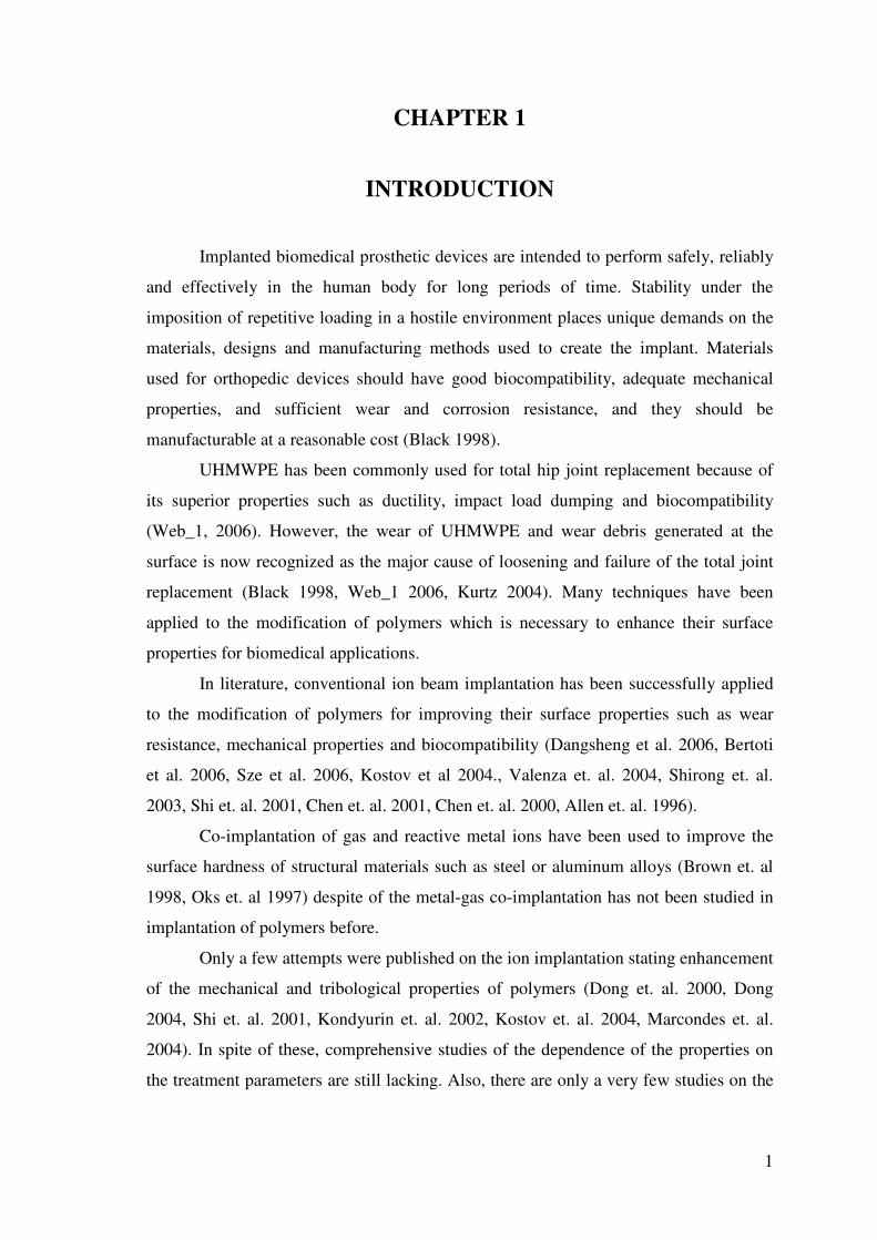
Figure 2.3. Components of artificial hip joints
(Source: Kurtz, 2004)
In Figure 2.3, the femoral component is made of a cobalt chromium, with a
ceramic femoral head, hydroxyapatite coating and a nitrided surface finish, which
hardens the surface of the stem and helps prevent scratching and the release of metal
wear debris (Kurtz 2004). However, there is one more parameter, which plays an
important role in implant design i.e., is cost. Material scientists are constantly faced
with the challenge of producing optimum material properties at minimum cost. In this
respect, UHMWPE is one of the general materials used for hip replacement. Its main
disadvantage is its wear resistance when used as a concave acetabular cup in a total hip
replacement (Black 1998, Web_1 2006, Kurtz 2004).
2.2. Ultra High Molecular Weight Polyethylene
Ultra-high molecular weight polyethylene (UHMWPE) is a type of polymer
classified as a linear homopolymer. Polyethylene is a polymer formed from ethylene
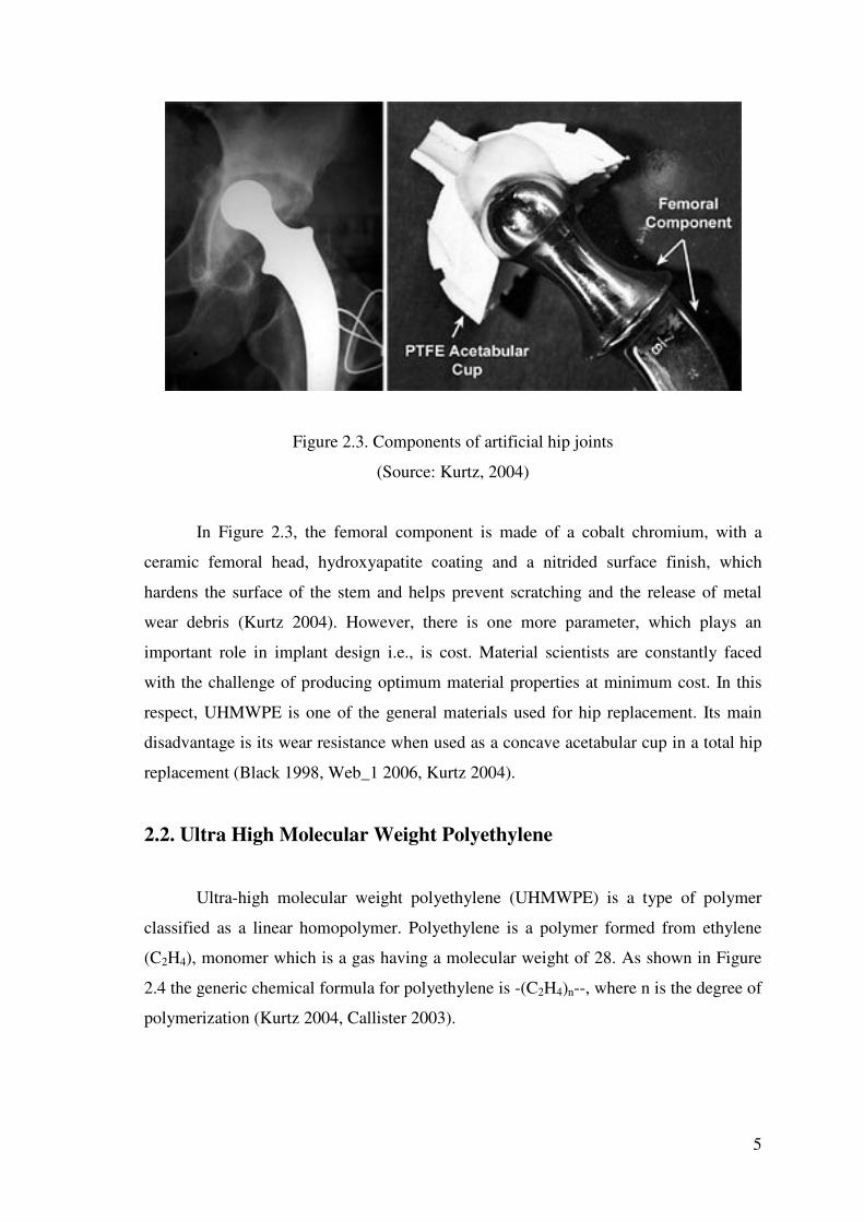
(C2H4), monomer which is a gas having a molecular weight of 28. As shown in Figure
2.4 the generic chemical formula for polyethylene is -(C2H4)n--, where n is the degree of
polymerization (Kurtz 2004, Callister 2003).
6
(a.) (b.)
Figure 2.4. A schematic of the chemical structures for ethylene (a.) and
Polyethylene (b.) (Source: Kurtz 2004)
For an ultra-high molecular weight polyethylene, the molecular chain can
consist of as many as 200,000 ethylene repeat units. Put another way, the molecular
chain of UHMWPE contains up to 400,000 carbon atoms (Kurtz 2004).
There are several kinds of polyethylene (LDPE, LLDPE, HDPE, UHMWPE)
which are synthesized with different molecular weights and chain architectures. LDPE
and LLDPE refer to Low Density Polyethylene and Linear Low Density Polyethylene,
respectively. These polyethylenes generally have branched and linear chain
architectures, respectively, each with a molecular weight of typically less than 50,000
g/mol (Kurtz 2004).
High Density Polyethylene (HDPE) is a linear polymer with a molecular weight
of up to 200,000 g/mol. UHMWPE, in comparison, has a viscosity average molecular
weight of 6,000,000 g/mol. In fact, the molecular weight is so "ultra-high" that it cannot
be measured directly by conventional means and must instead be inferred by its intrinsic
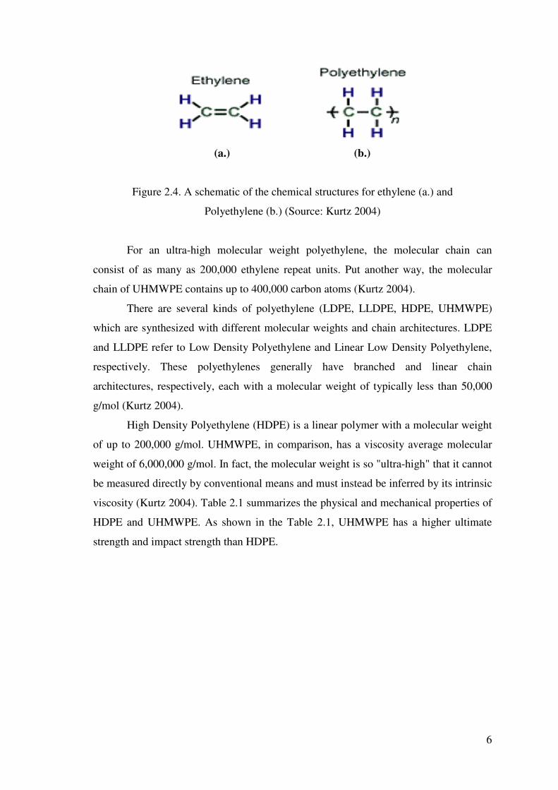
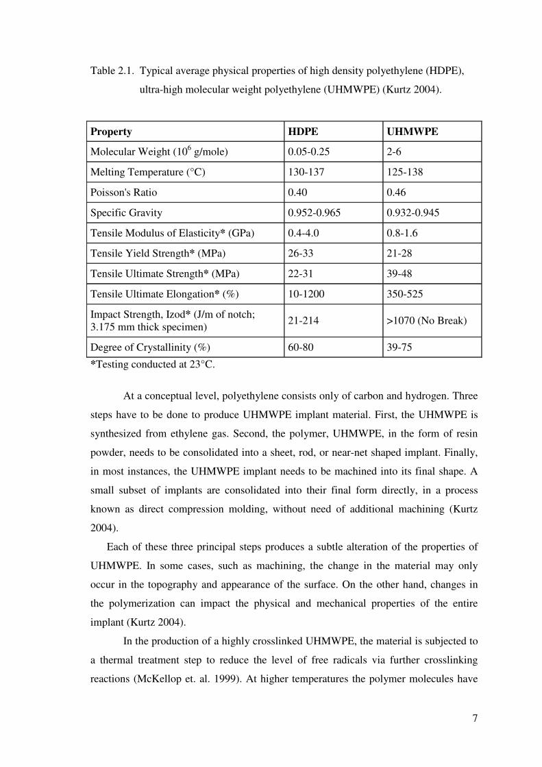
viscosity (Kurtz 2004). Table 2.1 summarizes the physical and mechanical properties of
HDPE and UHMWPE. As shown in the Table 2.1, UHMWPE has a higher ultimate
strength and impact strength than HDPE.
7
Table 2.1. Typical average physical properties of high density polyethylene (HDPE),
ultra-high molecular weight polyethylene (UHMWPE) (Kurtz 2004).
Property HDPE UHMWPE
Molecular Weight (106 g/mole) 0.05-0.25 2-6
Melting Temperature (°C) 130-137 125-138
Poisson's Ratio 0.40 0.46
Specific Gravity 0.952-0.965 0.932-0.945
Tensile Modulus of Elasticity* (GPa) 0.4-4.0 0.8-1.6
Tensile Yield Strength* (MPa) 26-33 21-28
Tensile Ultimate Strength* (MPa) 22-31 39-48
Tensile Ultimate Elongation* (%) 10-1200 350-525
Impact Strength, Izod* (J/m of notch; 3.175 mm thick specimen) 21-214 >1070 (No Break)
Degree of Crystallinity (%) 60-80 39-75
*Testing conducted at 23°C.
At a conceptual level, polyethylene consists only of carbon and hydrogen. Three
steps have to be done to produce UHMWPE implant material. First, the UHMWPE is
synthesized from ethylene gas. Second, the polymer, UHMWPE, in the form of resin
powder, needs to be consolidated into a sheet, rod, or near-net shaped implant. Finally,
in most instances, the UHMWPE implant needs to be machined into its final shape. A
small subset of implants are consolidated into their final form directly, in a process
known as direct compression molding, without need of additional machining (Kurtz
2004).
Each of these three principal steps produces a subtle alteration of the properties of
UHMWPE. In some cases, such as machining, the change in the material may only
occur in the topography and appearance of the surface. On the other hand, changes in
the polymerization can impact the physical and mechanical properties of the entire
implant (Kurtz 2004).
In the production of a highly crosslinked UHMWPE, the material is subjected to
a thermal treatment step to reduce the level of free radicals via further crosslinking
reactions (McKellop et. al. 1999). At higher temperatures the polymer molecules have
8
increased mobility, thereby increasing the probability of free radicals on adjacent chains
reacting to form crosslinks. For the thermal treatment to be effective at eliminating all
free radicals, it must be conducted at 150°C, above the melt temperature of the material.
Heating above the melting temperature destroys the crystalline regions of the material
thus making the free radicals that were in the crystals available for crosslinking. The
disadvantage of melting is the reduction crystal size and in material yield and the
ultimate strength that ensues. A compromise solution is to heat the material to just
below the melting temperature. This solution preserves the original crystal structure,
retains mechanical properties, and makes more free radicals available for crosslinking
than would be available without thermal treatment while still retaining some free
radicals in the crystal domains. When thermal treatment is conducted below the melt
transition of 135°C, it is referred to as “annealing,” and above the melt transition, it is
called “remelting.” Typically, annealing is carried out at 130°C and does not eliminate
all free radicals, although the number is substantially reduced by the elevated
temperature(Kurtz 2004).
Keith at. al suggest that the residual free radicals muct be stabilized after
implantation prefarably by melting and not annealing. They observed that implanted
and annealed explants showed embrittlement, oxidation and increase in crystallinity but
implanted and melted UHMWPE explants showed no oxidation, no increase in
crystallinity and no embrittlement (Keith et. al 2005). On the other hand, Wang et. al
reported that either implanted and melted or implanted and annealed UHMWPE
material have demonstrated greatly reduced wear however, melted ones have reduces
fatigue strength while annealed ones may oxidize when exposed to the oxygen (Wang
et. al 2006). Nonetheless, they suggest that sequential implantation and annealing of
UHMWPE materials have equivalent crosslinking levels, have fatigue and mechanical
strength and have an oxidation resistance (Wang et. al 2006).
There are two main uses for them in total hip replacement. When the acetabular
component is monolithic, it is made of ultra-high-molecular-weight polyethylene
(UHMWPE); when it is modular, it consists of a metallic shell and an UHMWPE insert
(Web_1 2006, Kurtz 2004)
9
2.3 . Wear
The hip joint is a ball-and-socket joint, which derives its stability from congruity
of the implants, pelvic muscles, and capsule. The prosthetic hip components are
optimized to provide a wide range of motion without impingement of the neck of the
prosthesis on the rim of the acetabular cup to prevent dislocation. The design
characteristics must enable implants to support loads that may reach more than 8 times
body weight (Black 1998, Web_1 2006). Proper femoral neck length and correct
restoration of the center of motion and femoral offset decrease the bending stress on the
prosthesis-bone inter- face. High stress concentration or stress shielding may result in
bone resorption around the implant. For example, if the femoral stem is designed with
sharp corners (diamond-shaped in a cross- section), the bone in contact with the corners
of the implant may necrose and resorb (Black 1998, Web_1 2006).
Load bearing and motion of the prosthesis produce wear debris from the
articulating surface and from the interfaces where there is micromotion. The principal
source of wear under normal conditions is the UHMWPE-bearing surface in the cup.
Several hundred thousands of particles are generated with each step, and a large
proportion of these particles are smaller then one micron (Kurtz 2004). Cells from the
immune system of the host are able to identify the polyethylene particles as foreign and
initiate a complex inflammatory response. This response may lead to rapid focal bone
loss (osteolysis), bone resorption, loosening, and/or fracture of the bone. Numerous
efforts are underway to modify the material properties of UHMWPE, to harden and
improve the surface finish of the femoral head, and to develop other bearing couples, for
example, ceramic-to-ceramic and metal-to-metal (Black 1998, Web_1 2006, Kurtz
2004, Callister, 2003)
Wear of UHMWPE is currently recognized as the primary culprit responsible for
aseptic loosening and late revision of hip replacements. Researchers have estimated that
for each day of patient activity, around a hundred million microscopic UHMWPE wear
particles are released into the tissues surrounding the hip joint. This particulate wear
debris can initiate a cascade of adverse tissue response leading to osteolysis (bone
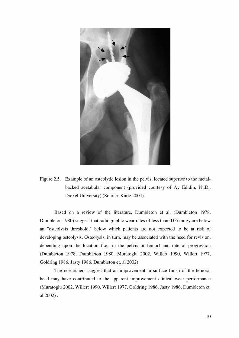
death) and ultimately aseptic loosening of the components (Kurtz 2004). In Figure 2.5,
radiograph shows an example of an osteolytic lesion in the pelvis.
10
Figure 2.5. Example of an osteolytic lesion in the pelvis, located superior to the metal-
backed acetabular component (provided courtesy of Av Edidin, Ph.D.,
Drexel University) (Source: Kurtz 2004).
Based on a review of the literature, Dumbleton et al. (Dumbleton 1978,
Dumbleton 1980) suggest that radiographic wear rates of less than 0.05 mm/y are below
an "osteolysis threshold," below which patients are not expected to be at risk of
developing osteolysis. Osteolysis, in turn, may be associated with the need for revision,
depending upon the location (i.e., in the pelvis or femur) and rate of progression
(Dumbleton 1978, Dumbleton 1980, Muratoglu 2002, Willert 1990, Willert 1977,
Goldring 1986, Jasty 1986, Dumbleton et. al 2002)
The researchers suggest that an improvement in surface finish of the femoral
head may have contributed to the apparent improvement clinical wear performance
(Muratoglu 2002, Willert 1990, Willert 1977, Goldring 1986, Jasty 1986, Dumbleton et.
al 2002) .
11
The crosslinking produced by a single dose of gamma radiation (even in air) has
the beneficial result of increasing the resistance to adhesive/abrasive wear. According to
wear testing by Wang et al. using a contemporary multidirectional hip simulator,
changing from 0 to 2.5 Mrads of irradiation (in air) drops the wear rate from 140 to 90
mm3/million cycles (using 32 mm diameter heads), corresponding to a reduction of
about 36% (Wang, 1997).
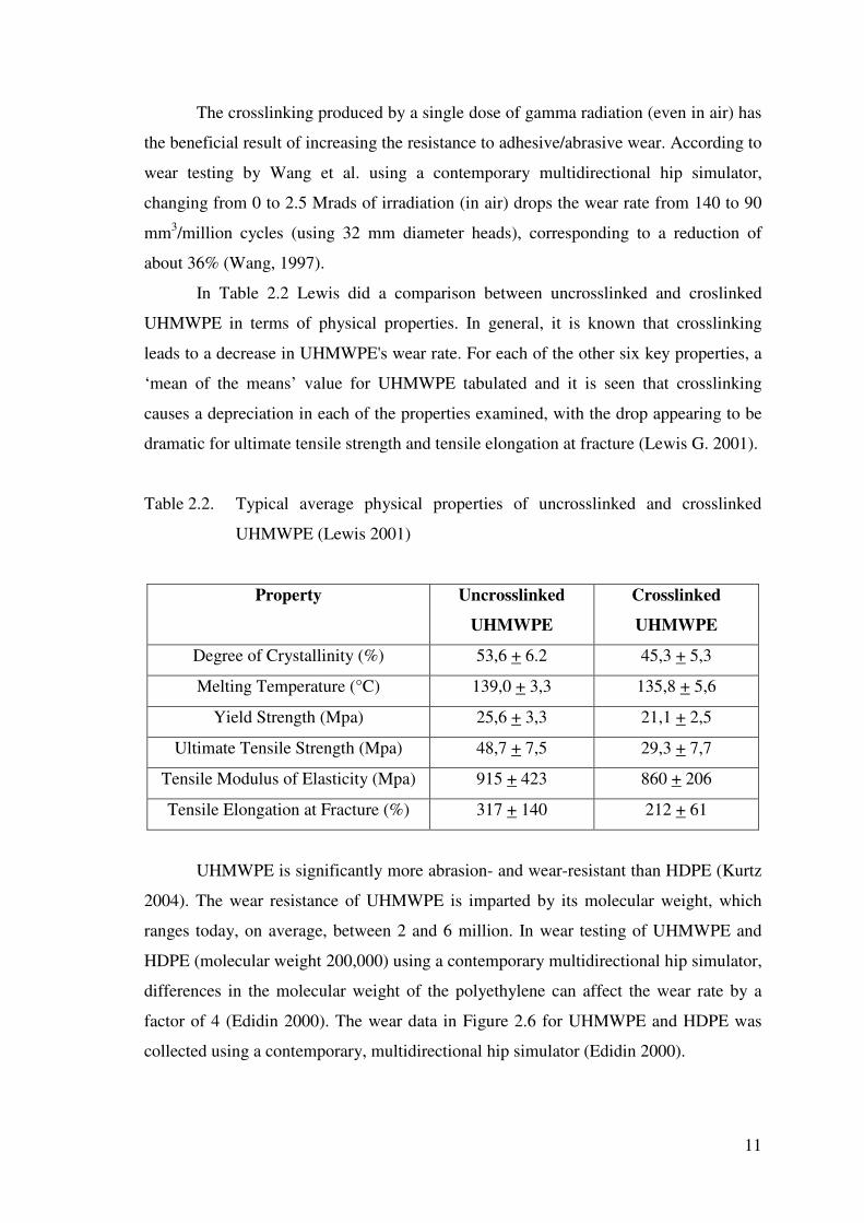
In Table 2.2 Lewis did a comparison between uncrosslinked and croslinked
UHMWPE in terms of physical properties. In general, it is known that crosslinking
leads to a decrease in UHMWPE's wear rate. For each of the other six key properties, a
‘mean of the means’ value for UHMWPE tabulated and it is seen that crosslinking
causes a depreciation in each of the properties examined, with the drop appearing to be
dramatic for ultimate tensile strength and tensile elongation at fracture (Lewis G. 2001).
Table 2.2. Typical average physical properties of uncrosslinked and crosslinked
UHMWPE (Lewis 2001)
Property Uncrosslinked
UHMWPE
Crosslinked
UHMWPE
Degree of Crystallinity (%) 53,6 + 6.2 45,3 + 5,3
Melting Temperature (°C) 139,0 + 3,3 135,8 + 5,6
Yield Strength (Mpa) 25,6 + 3,3 21,1 + 2,5
Ultimate Tensile Strength (Mpa) 48,7 + 7,5 29,3 + 7,7
Tensile Modulus of Elasticity (Mpa) 915 + 423 860 + 206
Tensile Elongation at Fracture (%) 317 + 140 212 + 61
UHMWPE is significantly more abrasion- and wear-resistant than HDPE (Kurtz
2004). The wear resistance of UHMWPE is imparted by its molecular weight, which
ranges today, on average, between 2 and 6 million. In wear testing of UHMWPE and
HDPE (molecular weight 200,000) using a contemporary multidirectional hip simulator,
differences in the molecular weight of the polyethylene can affect the wear rate by a
factor of 4 (Edidin 2000). The wear data in Figure 2.6 for UHMWPE and HDPE was
collected using a contemporary, multidirectional hip simulator (Edidin 2000).

12
Figure 2.6 Wear data for UHMWPE and HDPE
(Source: Edidin, 2000)
On the other hand, frictional resistance during twisting of the joint would be
reduced by a smaller femoral head (Web_1, 2006). The concern was that the friction
imparted to the joint during normal walking could lead to loosening of the cup from the
acetabulum. This theory was judged to be valid because the joint surfaces were not
intended to be lubricated hydrodynamically. In a hydrodynamic bearing, having a large
femoral head would be an asset, because the surface sliding speeds would be greater,
facilitating the development of a fluid film to separate the articulating surfaces. In an
artificial joint, in which the surfaces would always be in contact, in this respect,
reducing the frictional resistance of the joint was a major concern (Web_1, 2006).
In Figure 2.7, three interim implant designs, preserved in the collection at
Wrightington Hospital, are shown (Kurtz 2004). The components were retrieved at
revision surgery and are severely worn. The wear is most evident in the sectioned 25.3-
mm diameter acetabular component. The femoral components, on the other hand,
appear pristine. The femoral heads are polished to a mirror finish.

13
�
Figure 2.7. Three interim implant designs
(Source: Kurtz, 2004)
In summary, the following three factors reported by Kurtz (2004) ; either alone or in
combination, are so important that could explain the differences in wear rates:
1. Radiation-induced crosslinking
2. Molecular weight of the UHMWPE and
3. Surface finish of the femoral head.
The surface finish of the heads, suggested by Griffith (Griffith 1978), is a
possible, but unlikely reason for the change in clinical wear rates. A wide range in
surface roughness values were observed in Isaac's analysis of retrieved Charnley cups,
with no association to the clinical wear rate (Isaac 1996, Isaac 1992). Similarly, the
retrieval work of Hall et al. (Hall 1997) also showed no significant relationship between
surface roughness of the femoral head and clinical wear rate in a group of retrieved
metal-backed acetabular components that were implanted without cement. Thus, in light
of recently published studies, the roughness of the femoral head seems an unlikely
explanation for the change in wear behavior .

14
CHAPTER 3
ION IMPLANTATION OF POLYMERS
3.1. Principle of Technique
There are several new techniques that are being explored towards the surface
modification of polymers, which is necessary to enhance their surface properties for
biomedical applications. Ion implantation is an effective surface modification technique
which uses energetic ions to alter the outermost surfaces of polymers without affecting
their bulk properties (Chu 2002, BDM Federal Inc 1996, Anders 2000).
Technique of ion implantation was developed during the early 1960s as a
method to introduce precise quantities of electrically active or dopant ions into
semiconductor materials of micro-electronic devices. It is now the standart
semiconductor processing technique for providing these dopants (BDM Federal Inc
1996, Anders 2000).
The primary thrust in the attempts to commercialize ion implantation
technologies has been to modify surface properties such as wear and corrosion by
implanting appropriate alloying elements. Metal implants in contrast to semiconductor
implants require high fluences to effect the desired property changes. Furthermore the
process has been in competition with the other surface modification and coating
techniques such as electroplating, CVD, PVD and thermal spraying. Most of the other
techniques have thicker treatment depths and have been established in industrial
practice. Consequently, penetration of the commercial market in medical industry has
not been as successful as ion implantation studies in semiconductors (BDM Federal Inc
1996, Anders 2000).
Many researches has demonstrated that properties such as hardness, wear
resistance, coefficient of friction, fatigue strength, film adhesion and corrosion
resistance can be significantly improved by ion implantation technique (Chu 2002,
Dangsheng et al. 2006, Bertoti et al. 2006, Sze et al. 2006, Kostov et al 2004., Valenza
et. al. 2004, Shirong et. al. 2003, Shi et. Al 2001, Chen et al. 2001, Chen et. al. 2000,
Allen et. Al 1996). Dangsheng et. al. also reported that wettability of the alloy surfaces
were increased significantly after implantation (Dangsheng et al. 2006).

15
Even though ion implantation is relatively complex in terms of the equipment
required, it is a relatively simple process. By removing electrons from atoms in a
vacuum, a combination of positively charged ions and negatively charged electrons,
called a plasma is formed. Electric fields affect the plasma constituents. Positive
electrodes attract the negatively charged electrons and repel the positively charged ions;
negative electrodes attract the ions and repel the electrons (Anders 2000). Ion
implantation consists of basically two steps (BDM Federal Inc. 1996, Anders 2000):
1. Form a plasma of the desired material, and either
2. Extract the positive ions from the plasma and accelerate them toward the
target or find a means of making the surface to be implanted as the negative electrode of
a high voltage system.
The system to form the plasma is called the ion source; the system to move the
ions to the target is called the delivery system. The combination of the ion source and
the delivery system is called the accelerator (BDM Federal Inc. 1996, Anders 2000).
To better understand ion implantation, one can consider an analog with what
happens when a concrete wall is shot with bullets from a machine gun. In this process
the front surface of the wall is filled with bullets in the region close to the surface to a
depth dependent on the mass and velocity of the bullets. In the same way the surface of
a material struck by an ion beam will contain ions, be they gaseous or metal from the
ion beam. Unlike the bullet analogy, though implanted ions can combine chemically
with the surface material. Additionally, whereas the wall is weakened by the bullet
damage, the damage caused by ion implantation has actually been found to enhance the
properties by creating dislocations that suppress crack formation. This dislocation
network has been found to contribute to increased hardness and wear resistance
(Rodriquez et.al., 2005).
Typical energies used for industrial ion implantation surface treatment are
between 10.000 eV and 200.000 eV and typical depth of ion penetration is a fraction of
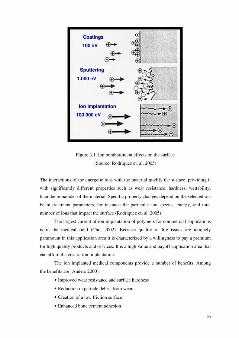
a micron. In Figure 3.1, ion bombardment effects on the surface are shown. Ion
implantation is a ballistic treatment. Depending on the bombardment energy, the
dominant effect on the surface can be very different (Rodriquez et. al. 2005). In Figure
3.1, ion bombardment effects on the surface of a material due to the different energies
has shown.
16
Figure 3.1. Ion bombardment effects on the surface
(Source: Rodriquez et. al. 2005)
The interactions of the energetic ions with the material modify the surface, providing it
with significantly different properties such as wear resistance, hardness, wettability,
than the remainder of the material. Specific property changes depend on the selected ion
beam treatment parameters, for instance the particular ion species, energy, and total
number of ions that impact the surface (Rodriquez et. al. 2005)
The largest current of ion implantation of polymers for commercial applications
is in the medical field (Chu, 2002). Because quality of life issues are uniquely
paramount in this application area it is characterized by a willingness to pay a premium
for high quality products and services. It is a high value and payoff application area that
can afford the cost of ion implantation.
The ion implanted medical components provide a number of benefits. Among
the benefits are (Anders 2000):
• Improved wear resistance and surface hardness
• Reduction in particle debris from wear
• Creation of a low friction surface
• Enhanced bone cement adhesion
Coatings 100 eV
1.000 eV
100.000 eV
Sputtering
Ion Implantation
17
• Improved corrosion resistance
• Preservation of bulk material properties
• Biocompatibility
Examples of the ion implanted devices include hip replacements, knee joints,
shoulder implants, spinal screws and dental implants.
3.2. Ion Implantation Methods
There are three methods commonly used for ion implantation. They differ in the
way in which they either form the plasma or make the surface to be implanted the
negative electrode. The three methods are mass analyzed ion implantation (MAII),
direct ion implantation (DII) and plasma source ion implantation (PSII). All three
methods are performed in a high vacuum chamber. They are isolated by the vacuum
chamber from the outside environment. (BDM Federal Inc 1996, Anders 2000). These
three methods are further discussed below:
3.2.1. Mass Analyzed Ion Implantation (MAII)
MAII is the technique that is used in semiconductor processing. A typical MAII
system is shown in Figure 3.2 . In MAII, the plasma that is formed in the ion source is
not pure, it contains materials that one does not wish to implant. Thus, these
contaminants must be separated from the plasma. To perform this separation, the
plasma source is placed at a high voltage and the part to be implanted is placed at a
ground. This produces a situation where the target is at a negative potential with respect
to the plasma source. A negative electrode then extracts the ions from the source. The
ions are then accelerated by a high voltage source to the target (BDM Federal Inc.
1996).

18
Figure 3.2. Schematic of mass analyzed ion implantation system
(Source: BDM Federal Inc, 1996).
Between the ion source and the target is a large magnet, with magnetic field
perpendicular to the direction of ion motion. Ions passing through this magnetic field
are bent by the magnetic field. The amount of bending depends on the ion material
being implanted and the strength of the magnet. Heavy ions bend less than light ions.
By proper selection of the magnetic field, the desired ions can be steered to the target,
while the undesirable ions can be expelled from the system (BDM Federal Inc. 1996).
The need for the magnets to separate the desired ions from the undesired ions
makes mass analyzed ion implantation very expensive, especially for applications where
existing simple processes produce similar or better results. The magnet is costly to build
and consumes a very large amount of energy. In addition, the spread of the ions, or the
ion beam must be small in order to be properly bent to the target, but the number of ions
cannot be very high because self-repulsion (remember that all of the ions have a positive
charge) will cause the beam to diffuse. For the formation of metal ions, mass analyzed
ion implantation can also present a toxicity problem. To obtain high currents of metal
ions, a plasma source is usually used that forms the plasma by initiating an electric
discharge in chlorine or other toxic gas (BDM Federal Inc. 1996).
The great advantage of MAII system is that they can be used to generate an ion
beam of every element in the periodic table. Moreover, the ion beams that are
generated, because of the bending magnet, are extremely pure. MAII is used extensively
in the electronics industry to dope semiconductors precisely because such purity is very
important. For other ion implantation applications, though, such as metal finishing

19
applications, mass analyzed systems are less useful because of their high costs, limited
throughput and toxicity concerns (BDM Federal Inc. 1996).
3.2.2. Direct Ion Implantation (DII)
DII eliminates the need for the current limiting magnet found in MAII by using
an ion source that produces a plasma and ion beam of the just desired material. A
typical DII system is shown in Figure 3.3. In DII, the plasma is formed in the ion source
and the ions are extracted at high energies in a wide beam, passing through a valve
directly into the end station, where they ion implant parts within the target area (BDM
Federal Inc. 1996).
Figure 3.3. Schematic of direct ion implantation system
(Source: BDM Federal Inc.1996).
In such a case, the beam current can be high (10-50 mA), costs are greatly
reduced, and relatively high throughput processing is possible. For uniform
implantation of workpieces with curved or multiple surfaces, though, either the beam
has to be rastered across the surface of the piece or the workpiece must be handled with
a rotating or tilting platen or some other manipulator. As will be discussed below, the
primary ion species used for direct ion implantation of metals are nitrogen gas and
metal vapor (BDM Federal Inc. 1996).

20
3.2.3. Plasma Source Ion Implantation (PSII)
A final variation of the ion implantation process is the simplest in concept: make
the material to be implanted the negative electrode. Figure 3.4 depicts a typical PSII
system. In PSII (some times referred as plasma ion immersion), the plasma source
floods the chamber of the end station with plasma. Ions are extracted from the plasma
and directed to the surface of the part being ion implanted by biasing the part to very
high negative voltages using a pulsed, negative high voltage power supply. Because of
the bias, the ions impinge virtually at nearly 90 degrees to all of the external surfaces,
the optimum ion implantation angle (BDM Federal Inc. 1996)
Figure 3.4. Schematic of plasma source ion implantation system
(Source: BDM Federal Inc. 1996)
While PSII is the simplest in concept, it is perhaps the most difficult in practice
of the three ion implantation methods. To make this process work, the negative bias
voltage imparted to the part to be implanted must be pulsed with a very short pulse
length. Otherwise, an arc will form between the part to be implanted and the chamber
walls or other grounded electrodes, damaging or destroying the parts. A second problem
is regulating the amount of plasma that hits the surfaces of the part and regulating where
it goes. Ion beams are easy to measure and direct; plasmas are not (BDM Federal Inc.
1996)
21
PSII also lacks the versatility of MAII or DII. It cannot treat insulators without
additional equipment, adding to the system complexity. It is virtually limited to gas ions
(BDM Federal Inc. 1996).
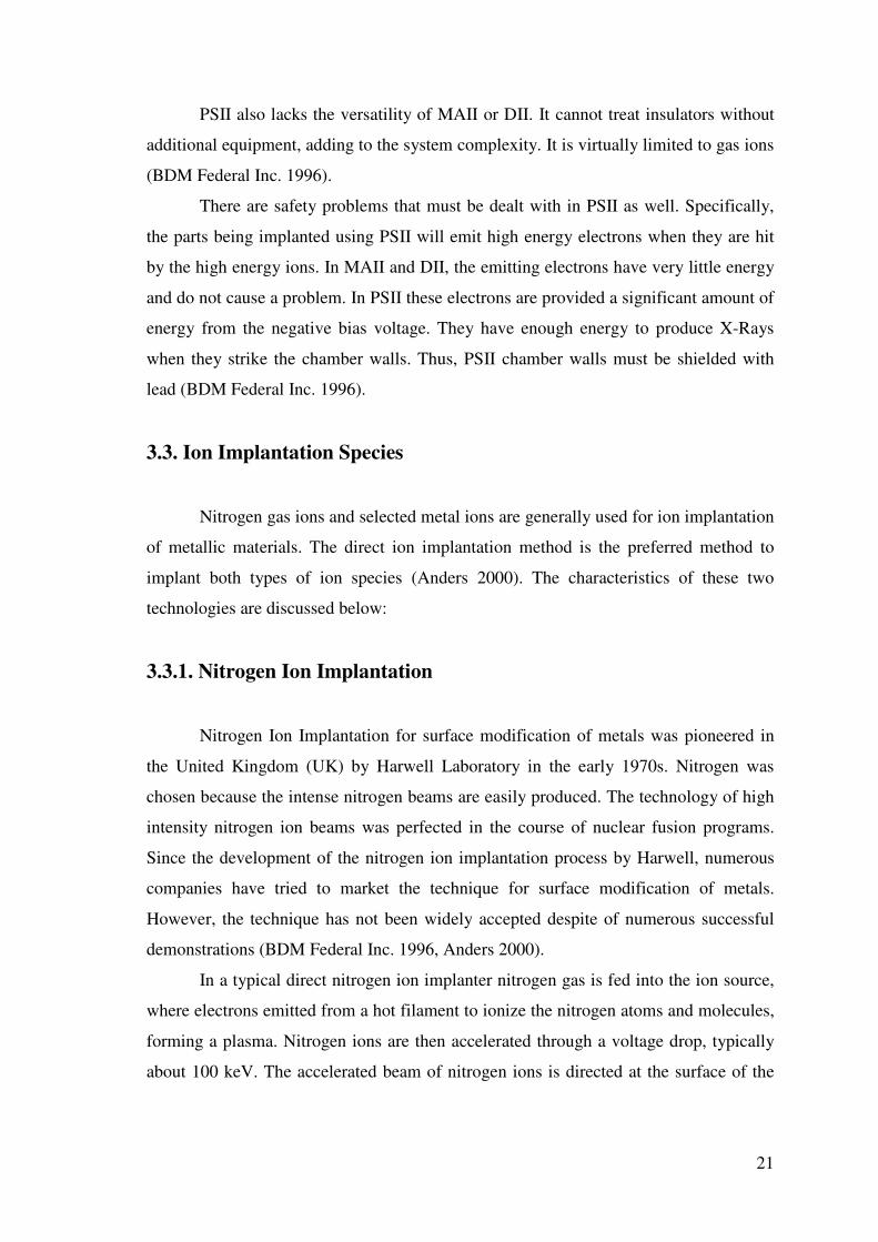
There are safety problems that must be dealt with in PSII as well. Specifically,
the parts being implanted using PSII will emit high energy electrons when they are hit
by the high energy ions. In MAII and DII, the emitting electrons have very little energy
and do not cause a problem. In PSII these electrons are provided a significant amount of
energy from the negative bias voltage. They have enough energy to produce X-Rays
when they strike the chamber walls. Thus, PSII chamber walls must be shielded with
lead (BDM Federal Inc. 1996).
3.3. Ion Implantation Species
Nitrogen gas ions and selected metal ions are generally used for ion implantation
of metallic materials. The direct ion implantation method is the preferred method to
implant both types of ion species (Anders 2000). The characteristics of these two
technologies are discussed below:
3.3.1. Nitrogen Ion Implantation
Nitrogen Ion Implantation for surface modification of metals was pioneered in
the United Kingdom (UK) by Harwell Laboratory in the early 1970s. Nitrogen was
chosen because the intense nitrogen beams are easily produced. The technology of high
intensity nitrogen ion beams was perfected in the course of nuclear fusion programs.
Since the development of the nitrogen ion implantation process by Harwell, numerous
companies have tried to market the technique for surface modification of metals.
However, the technique has not been widely accepted despite of numerous successful
demonstrations (BDM Federal Inc. 1996, Anders 2000).
In a typical direct nitrogen ion implanter nitrogen gas is fed into the ion source,
where electrons emitted from a hot filament to ionize the nitrogen atoms and molecules,
forming a plasma. Nitrogen ions are then accelerated through a voltage drop, typically
about 100 keV. The accelerated beam of nitrogen ions is directed at the surface of the
22
part to be implanted in the vacuum chamber. This is the same process described in
Direct Ion Implantation Part (BDM Federal Inc. 1996, Anders 2000).
The studies related to Nitrogen ion implantation show increases in wear and
fatigue resistance, lubricity, and in some cases, corrosion resistance of metal surfaces
(Budzynski et. al. 2006, Cheng et. al. 2006, Yang et. al. 2006, Ozturk et. al. 2005) . In
addition, nitrogen ion implantation has been found to increase the wear life of parts
treated with hard chromium (hexavalent chromium) electroplate by between 5 and 10
times. Thus, nitrogen ion implantation has the added environmental benefit of reducing
the need to perform the hard chromium electroplating process by extending the life of
the electroplated coating (Kwon et. al. 2006, Ferber et. al. 1991, Fischer et. al. 1991).
Many researchers also have studied N ion implantation on polymers, and again
found that wear resistance was improved (Bertóti et al. 2006, Allen et. al. 1996, Chen et
al. 2001, Liu et al. 1996, Dong et. al. 2000). Dong et al. (Dong et al. 2000) and Kim et.
al. (Kim et. al. 2006) reported that improvement in surface wettability after
implantation.
Valenza et al. (Valenza et. al 2004), Sze et. al. (Sze et. al. 2006) and Sheeja et al.
(Sheeja et. al. 2005) also reported that improvement in hardness and friction with the N
ion implantation on UHMWPE.
3.3.2. Metal Ion Implantation
Metal Vapor ion implantation is a recent development among the ion
implantation techniques. The technological development that led to the development of
this process was the invention of the metal vapor vacuum arc (MEVVA) ion source at
Lawrence Berkeley Laboratory ISM technologies in San Diego (BDM Federal Inc
1996). Figurthe first Vacuum Arc Ion Source based metal ion implantation facility was
built with TUBITAK support in Izmir by Öztarhan et. al. (Öztarhan et. al 2004). In
Figures 3.6 and 3.7, MEVVA Source and its components are shown.
Similar to the source used in Nitrogen ion implantation, the MEVVA source
bombards a workpiece’s surface with accelerated ions. In the case of the MEVVA
source, though, metal vapor ions are used instead of Nitrogen gas ions. Chromium,
nickel, platinium and titanium are metal elements that have been implanted using this
process (Oks 1997).
23
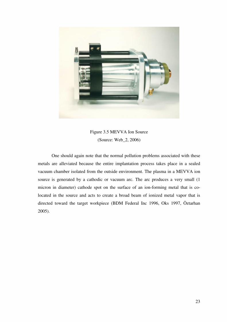
Figure 3.5 MEVVA Ion Source
(Source: Web_2, 2006)
One should again note that the normal pollution problems associated with these
metals are alleviated because the entire implantation process takes place in a sealed
vacuum chamber isolated from the outside environment. The plasma in a MEVVA ion
source is generated by a cathodic or vacuum arc. The arc produces a very small (1
micron in diameter) cathode spot on the surface of an ion-forming metal that is co-
located in the source and acts to create a broad beam of ionized metal vapor that is
directed toward the target workpiece (BDM Federal Inc 1996, Oks 1997, Öztarhan
2005).

24
Figure 3.6. MEVVA source and its components
(Source: Web_2, 2006)
Figure 3.7. MEVVA ion source disassembled
(Source: Web_2, 2006)
25
The MEVVA source makes use of the principle of vacuum arc discharge
between the cathode and the anode to create a dense plasma from which an intense
beam of metal ions of the cathode material is extracted (Oks et. al. 1997, Öztarhan et. al.
2005).
Energies of the ions can be calculated via time of flight method. The time of flight
(TOF) method for measuring particle mass-to-charge ratio is done as follows. An ion of
known electrical charge and unknown mass enters a mass spectrometer and is accelerated
by an electrical field of known strength. This acceleration results in any given ion having
the same kinetic energy as any other ion given that they all have the same charge. The
velocity of the ion will depend, however, on the mass-to-charge ratio.The time that it
subsequently takes for the particle to reach a detector at a known distance is measured.
This time will depend on the mass-to-charge ratio of the particle (heavier particles reach
lower speeds). From this time and the known experimental parameters one can find the
mass-to-charge ratio of the particle. This method of analysis is a powerful tool for finding
the mass-to-charge ratio of charged particles, atoms and molecules (Gushenets et. al
2006). For example, the ion implantion system in Izmir used successfully the TOF
equipment developed by Oks et al. (Gushenets et. al 2006).
A broad beam of high peak beam current of the order of about one ampere and a
mean beam current of tens of milli-amperes can be obtained. Due to its high-current and
broad-beam capabilities, the MEVVA ion source is employed to solve the throughput
problem arising from the high implantation dose. The flexibility is achieved by using
vacuum arc ion sources. Most metallic elements or combinations of metallic elements of
the periodic table can be implanted and simultaneous implantation of gas and metal ions
is possible (Oks et. al.1997, Öztarhan et. al. 2005).
Metal ion implantation of polymers have studied by ISM Technologies
Corporation in San Diego, CA worked with Oak Ridge National Laboratory (ORNL).
They found that the implantation of polymers with low doses of chromium and titanium
leads to very large increases in surface hardness. Metal ion implantation can also be
used to reduce or eliminate hydrogen embrittlement. Platinum implanted into surfaces
serves as a catalyst which accelerates the recombination of hydrogen atoms into
molecules so that they do not diffuse into the surface. Other implanted materials can
form barriers to hydrogen as well. ISM has investigated the use of metal ion
implantation as a pre treatment for chromium plating which would reduce the effects of
hydrogen embrittlement. Metal ion implantation has an advantage over conventional ion

26
implantation because there is no gas loading problem. At currents of 1-2 A., there is a
big problem with pumping out gas in conventional ion implantation systems. The same
principle allows independent control of the pressure of deposition. The mixing of
reactive gases is also much easier (BDM Federal Inc 1996)
In literature, Wu et al studied the implantation of PET with MEVVA source.
They implanted W ions on PET surface and they observed that the changes occurred in
the structure, wear resistance and electrical properties of PET after W ion implantation.
(Wu 2003). Co-implantation of gas and reactive metal ions have been used to increase
the surface hardness of structural materials such as steel or aluminum alloys. Zirconia
and alumina, for instance, have been produced by co-implantation of Zr+O and Al+O
respectively. Brown et. al (Brown et. al. 1998) and Oks et al. (Oks et. al 1997) studied
metal gas co-implantation with Pt+N, Ti+N, Al+O and Zr+O and they observed
significant improvement in wear, hardness and friction parameters. Davenas et. al
studied silver implanted polyethylene at 10, 15 and 50 keV and they observed that C=C
bond formation and dehdrogenation on the surface. They also observed that
graphitization on the surface layer after implantaion of Ag. (Davenas et. al 2002).
3.4. Ion Implantation of UHMWPE
Generally, the ion implantation of polyethylene with ionizing radiations induces
de-hydrogenation and carbon enrichment. The ion bombardment, modifies strongly the
polymer chains especially along the ion track. The resulting polymer shows a surface
layer rich of cross-linked ‘graphite-like’ structure with special properties especially
effective on wear mechanisms (Kurtz 2004).
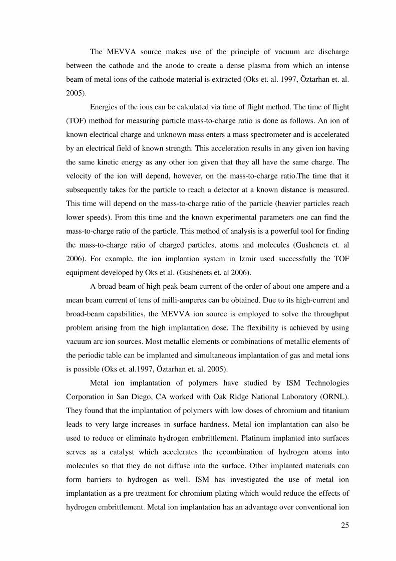
Ion implantation chemistry of UHMWPE is shown in detail in Figure 3.8
Several mechanisms can be occurred during ion implantation like chain scission,
crosslinking, radical formation, ionization and double bond formation (Kurtz 2004).
27
Figure 3.8. Ion implantation effects on UHMWPE
(Source: Qureshi et. al., 2005)
The mechanism behind this improvement is, ion implantation produce free
radicals (unpaired electrons) in the polyethylene, which in secondary chemical reactions
leads to a combination of crosslinking and chain scission. Crosslinking is beneficial for
reducing wear. Chain scission produces a decrease in molecular weight, with
concomitant reduction of wear resistance and mechanical properties. When ion
implantation is conducted in the presence of oxygen, scission predominates over
crosslinking. However, when conducted in an inert environment, such as nitrogen,
crosslinking predominates over scission. Regardless of whether implantation is
conducted in air or in an inert environment, some of the free radicals will remain
entrapped within the crystalline phase of the UHMWPE. Over time, these entrapped
free radicals can migrate to the surface of crystals. These free radicals react with
available oxygen causing further time-dependent chemical degradation (Wang et. al.
2006)
In the literature, it was reported that increased crosslinking improves the wear
performance of UHMWPE compared to conventional material. However, the presence
of the crosslinks adversely affects uniaxial ductility, and the uniaxial failure strain of
28
UHMWPE decreases linearly with increasing implantation dose (Lewis 2001). During
implantation, the loss of ductility depends on the crystalline microstructure of the
UHMWPE, because crosslinking occurs primarily in the amorphous phase, where the
molecular chains are in sufficient proximity such that a covalent bond can be created
between adjacent polymer molecules by the applied energy (Wang 2006). Unimplanted
UHMWPE typically has a crystallinity in the region of 50%, so the other 50% of the
material is amorphous that could be crosslinked during irradiation. If the temperature of
the UHMWPE changes during the crosslinking process, this can influence the
distribution of crosslinking in the polymer and, hence, influence its ability to
accommodate large strains prior to failure (Kurtz 2004).
In recent literature, plasma based ion implantation of nitrogen on UHMWPE
was performed by Bertoti et. al. (Bertoti et. al. 2006). They applied 27.13 MHz RF
energized low pressure N2 plasma with 15–30 kV pulses and fluences up to 5 · 1017
ions/cm2. Surface compositional and structural alterations and nanomechanical property
changes were investigated by XPS, Raman and by nano-indentation and nano-scratch
techniques. The implanted N amounted up to 13–20 at.% (N/C = 0.18–0.30), while a
significant amount of oxygen could also be detected on the surface. Three types of
chemical states of the incorporated nitrogen were detected, related to linear sp2 C=N–C
and to planar and non-planar sp3 type C–N bonds. The applied PBII treatment led to
severe dehydrogenation of the polyethylene resulting in conversion of the surface into a
nitrogen-containing DLC type structure. Up to four-fold increase of the hardness at 50–
100 nm depth was measured compared to the untreated samples. They found that the
scratch volume, characterising the wear resistance, decreased also significantly down to
25–35% of the original value (Bertoti et. al. 2006). Kostov et. al. also studied non-line-
of-sight plasma immersion ion implantation (PIII) technique for the surface
modification of UHMWPE sample, immersed in nitrogen plasma, were pulsed through
a metallic grid at repetition rate of 100 Hz with negative high-voltage pulse of 15 kV
magnitude and 10 �s duration (Kostov et.al. 2004). They analyzed the surface structural
changes by laser Raman spectroscopy, X-ray photoelectron spectroscopy (XPS) and
optical microscopy. From the Raman spectra, it is observed that the chain structure of
UHMWPE has been damaged due to ion bombardment and a layer of dehydrogenated
amorphous carbon was formed. The ratio of sp3/sp2 bonded carbon in the modified layer
was obtained by suitable fitting of the XPS C 1s energy peak, using a four-curve fitting
procedure, which recognizes a portion of C–O and C=O surface bonding. The XPS

29
results for N 1s peak showed that the implanted nitrogen ions form chemical bonds with
the polymer instead of forming precipitates by self-clustering (Kostov et.al. 2004).
Sze and Tay studied on the improvement of the nano-hardness and tribological
properties of ultra-high molecular weight polyethylene (UHMWPE) using a filtered
cathodic arc source with substrate pulse biasing (Sze and Tay 2006). The filtered
cathodic arc source generated highly ionized carbon plasma and ions were accelerated
towards the substrate by the negative substrate pulse voltage. Graphitization, nano-
hardness and wear rate of the modified surfaces were systematically studied as a
function of pulse voltage (from − 3 kV to − 12 kV) and implantation time (from 1 min
to 20 min). Graphitization of the modified surfaces was observed using Raman and X-
ray photoelectron spectroscopes. They reported that heavy structural damages occured
on the surface of the UHMWPE at increasing pulse voltages. The nano-hardness of the
UHMWPE surfaces, measured at an applied load of 100 �N, was increased from 0.35
GPa to 1.6 GPa when implanted with carbon at a pulse voltage of − 10 kV for an
implantation time of 12 min (ion dose about 1.73 × 10¹⁷ atoms/cm2). This process of
graphitization was observed using Raman spectroscopy. Although it was difficult to
quantify the C–C bonds using XPS, they observed the existence of C–O and C=O bonds
which was attributed to oxidation when exposed to the environment. In their study, it
was finally concluded that highly ionized carbon plasma helped the polymer surface
react readily with carbon ions to form a graphite-like structure, which improved the
nano-hardness and tribological properties of UHMWPE (Sze and Tay 2006).
Valenza et. al. also studied tribological properties of ion implanted UHMWPE
surfaces (Valenza et. al. 2004). They studied surface modification of ultra high
molecular weight polyethylene (UHMWPE) induced by ion implantation of different
ions ( H, He, Ar, Xe) at 300 keV energy. The irradiated surfaces were investigated by
Raman spectroscopy, infrared absorption and micro-hardness analysis, scanning
electron microscopy. It was reported that pin on disc measurements valuated the wear of
the UHMWPE against a stainless steel probe; wear resistance increases of about 76%
after the ion implantation. They also found that after ion implantation micro hardness
values increased in the irradiated layers due to the high carbon surface concentration
and cross-linking effects in the polymeric chains (Valenza et. al. 2004).
Davenas et. al. investigated the efficacy of ion beam techniques to reduce
bacterial adhesion or to induce bactericidal activity of different polymer materials: PVC,
silicone rubber, poly(urethane) and poly(ethylene). It was reported that reduction of the

30
implantation energy to 10 keV led to activity enhancement resulting from the easier
accessibility of surface colloids evidenced by AFM microscopy (Davenas et. al. 2002).
Their study emphasized the specific processes induced by the formation of silver nano-
particles at low energy implantation, which differs basically from Ion Beam Assisted
Deposition (IBAD technique) leading to the formation of a continuous silver coating. It
was reported that two types of effects associated 1. to the intrinsic modifications of the
polymer and 2. to the implanted silver ions. At low irradiation fluences, limited changes
of the polymer were detected (IR) through the formation of unsaturated bonds of the
transvinylene and carbonyl types. However, the molecular structure disappeared for
fluences larger than 5×10¹⁵ Ag+ cm−2, whereas evidence for the formation of an
amorphous carbon layer is provided (Raman spectroscopy). As the irradiation energy
was lowered to 10 keV, the analysis of the UV edge showed that this carbon layer
became more diamond-like. As expected from the known antifouling properties of
diamond films, they found a reduction of the bacterial adhesion on the surface. It was
also seen that the formation of metallic silver particles appearing at fluences larger than
1016 Ag+ cm−2 was evidenced by different analytical techniques. Increased antibacterial
effect resulting from colloidal silver has been evidenced. They recommended that
studies at implantation energies below 10 keV, would then be of main interest for
further improvements of the bactericidal activity (Davenas et. al. 2002).
31
CHAPTER 4
EXPERIMENTAL
4.1. Material and Method
4.1.1. Material
Samples with medical grade GUR 1020 - Type 1 - Ultra High Molecular Weight
Polyethylene (UHMWPE) provided by Hipokrat Co. with a density of 945 kg/m3 were
used. 2 disk shaped samples with a diameter of 30mm and thickness of 4mm were
polished down to about surface roughness of 124,05 (nm) Ra.
4.1.2. Method
Samples were implanted at Russian Academy of Sciences Institute of High
Current Electronics (IHCE), Siberian Branch, in gas and vacuum discharges with Ag
and Ag+N ions by using MEVVA ion implanter with a fluence of 1017 ion/cm2,
extraction voltage of 30 kV and pulse rate of 1Hz. Target temperatures were less than
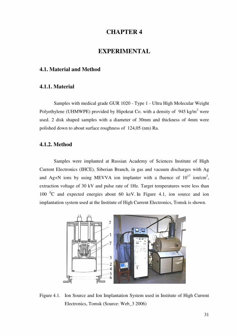
100 0C and expected energies about 60 keV. In Figure 4.1, ion source and ion
implantation system used at the Institute of High Current Electronics, Tomsk is shown.
Figure 4.1. Ion Source and Ion Implantation System used in Institute of High Current
Electronics, Tomsk (Source: Web_3 2006)

32
The ion source depends for its operation on two forms of arc discharge with a
common hollow anode initiated simultaneously or one after another (Web_3 2006).
A constricted discharge between cathode 1 and hollow anode 2 serves to generate gas
ions and initiate a vacuum arc (with the discharge operating time being 20s.). Metal ions
are generated in the cathode spots of the vacuum arc initiated between electrode 2 and
electrode 3. The ions are extracted from the plasma surface stabilized by fine-mesh
metal grid 4. The ions are accelerated to a required energy by a dc accelerating voltage
applied at the gap between hollow anode 2 and electrode 5. The latter consists of two
grids made of metal wires and showing a high geometrical transparency. The
accelerated ion beam is taken by a collector on which specimens or machine parts are
placed. To cut off the secondary electrons knocked out from the collector by the ions, a
negative potential of no less than 15 kV is applied to one of the grids of electrode 6.
Insulator 7 is filled with transformer oil. The source is cooled with water circulating
through a radiator. The source is capable to produce ion beams of any gases (except
oxygen) and metals (Web_3 2006). Specifications of the ion source are given below
(Web_3 2006).
Table 4.1 Specifications of Ion Source
(Source: Web_3 2006)
- Accelerating voltage 20-80 kV
- Vacuum arc current
- Constricted arc current
50-150 A
30-60 A
- Metal ion beam current
- Gas ion beam current
0.1-0.5 A
0.1-0.25 A
- Operating pulse repetition rates 12.5, 17, 25, 50 Hz
- Current pulse duration 400 µs
- Delay of vacuum arc initiation from constricted arc initiation 0-400 µs
- Ion beam cross-sectional area 250 cm2
- Vacuum arc operation time with-out changing the cathode 30 h
- Constricted arc operation time without changing the cathodes 100 h
- Source power supply voltage 3x380 V
- Excess pressure of compressed gas in the source 2-10 atm
33
4.2. Characterization and Properties
4.2.1. Ion Penetration Depth Analysis
In order to determine ion penetration depth and ion ranges in the UHMWPE
target, Stopping and Range of Ions into Matters (SRIM) simulation program was used
for the theoretical prediction of the ion penetration. Rutherford Back Scattering (RBS)
technique was used for the experimental determination of implanted ions penetration .
Next sections explain in detail these two techniques.
4.2.1.1. Stopping and Range of Ions into Matters (SRIM)
Depth of the ions is theoretically calculated with SRIM program. SRIM is a
group of programs which calculate the stopping and range of ions (up to 2 GeV/amu)
into matter using a quantum mechanical treatment of ion-atom collisions (assuming a
moving atom as an "ion", and all target atoms as "atoms"). This calculation is made
very efficient by the use of statistical algorithms which allow the ion to make jumps
between calculated collisions and then averaging the collision results over the
intervening gap. During the collisions, the ion and atom have a screened Coulomb
collision, including exchange and correlation interactions between the overlapping
electron shells. The ion has long range interactions creating electron excitations and
plasmons within the target. These are described by including a description of the target's
collective electronic structure and interatomic bond structure when the calculation is
setup (tables of nominal values are supplied). The charge state of the ion within the
target is described using the concept of effective charge, which includes a velocity
dependent charge state and long range screening due to the collective electron sea of the
target (Ziegler et. al. 1985).
4.2.1.2. Rutherford Back Scattering Analysis (RBS)
Knowledge on the thickness, composition, and interfaces of thin films and
multilayers, in many systems, is fundamental for the understanding and optimization of

34
their properties. One of the techniques often applied to such studies is Rutherford
backscattering (RBS) Analysis (Barradas 2001).
The thickness of the Ag and Ag+N layers is deduced from RBS measurements.
RBS analysis was done with 2.1 MeV He ions incident at 30° and detection angle at
170°. Depth distributions of Ag were calculated using the RUMP code (Doolittle 1985)
with the initial values given in Figure 4.2.
Figure 4.2. RUMP simulation data that we used for Ag and Ag+N implanted samples
Equations 4.1 and 4.2 were used for the determination of the thickness (th) of
the Ag layers . The RUMP layer thickness (th RUMP ) is based on the assumption of 1cm2
of UHMWPE containing 1015 atoms .
ρ = mass density (g / cm3,)
A = atomic mass (g / mole)
AvogadroN A = number
n = Density (atom/cm3 )
th = Real thickness
th RUMP = Thickness which is obtained by RUMP simulation
AN
n Aρ= (4.1)
th(cm) = th RUMP (atom/cm2) / n (atom/cm3) (4.2)
35
4.2.2. Chemical Characterization
In order to determine the damage products and structural changes in UHMWPE,
additional analytical techniques were employed on the implanted samples. The samples
were analyzed with optical absorption photospectrometry (OAP), for the ultraviolet–
visible region, Fourier transform infrared (FTIR) and Raman spectrometry.
4.2.2.1. Optical Absorption Photospectroscopy (OAP)
The samples were analyzed with optical absorption photospectrometry (OAP),
for the ultraviolet–visible region. Optical characterization of samples before and after
each treatment was carried out with a dual-beam spectrophotometer (Spectral
Instruments). The obtained optical spectra have 1-nm resolution covering the
wavelength range of 500–3500 nm.
4.2.2.2. Attenuated Total Reflectance /�Fourier Transform Infra Red
(ATR / FT-IR) Spectroscopy
ATR/FTIR spectrometry can provide valuable information related to the
chemical structure. ATR/FTIR spectrometry can also be used to identify unique features
on the thin layers after chemical surface modification. (Colthup et. al. 1990)
ATR- FTIR analysis was used to see if any new chemical bonds was formed 2
microns deep at the surface. Thermo Nicolet Nexus 670 model FTIR with Smart
DuraSampllR 3 Bounce diamond HATR (3 reflection diamond ATR) and OMNIC
software were used. Scans were done in the range of 500 - 4000 cm-1 wave number
region.
4.2.2.3. Raman Spectrocopy
Raman spectroscopy is a technique to study vibrational, rotational and other low
frequency modes in a system. It relies on inelastic scattering, or Raman scattering of
monochromatic light, usually from a laser in the visible, near infrared or near ultraviolet
range. Phonons or other excitations in the system are absorbed or emitted by the laser

36
light, resulting in the energy of the laser photons being shifted up or down. The shift in
energy gives information about the phonon modes in the system. Raman spectroscopy is
commonly used for vibrational information which is very spesific for the chemical
bonds in molecules. It therefore provides a fingerprint by which the molecule can be
identified (Colthup et. al. 1990).
Raman spectra were acquired using a LabRam spectrophotometer, using a He–
Ne laser with � = 632 nm which was focused on the sample surface by an Olympus BX-
40 microscope using a 100× objective lens. The scattered light was collected, in
backscattering geometry, by the same microscope. The results are compared with
identical untreated UHMWPE sample.
4.2.3. Thermal Analysis
Thermal analyses of untreated, Ag and Ag+N hybrid ion implanted UHMWPE
samples were conducted with DSC and TGA. % Crystallinity results are compared with
XRD.
4.2.3.1. Thermo Gravimetric Analysis (TGA) and Differential
Scanning Calorimetry (DSC)
Differential Scanning Calorimetry (DSC) is a thermal analysis technique which
is used to measure the temperatures and heat flows associated with the phase transitions
in materials as a function of time and temperature. Such measurements provide
qualitative and quantitative information about physical and chemical changes that
involve endothermic and exothermic processes, or changes in heat capacity (Web_4,
2006)
Thermo gravimetric Analysis (TGA) measures changes in weight of a polymeric
sample with increasing temperature. Moisture content and presence of volatile species
can be determined with this technique. Computer controlled graphics can calculate
weight percent losses (Web_4, 2006)
Thermal analysis of untreated, Ag and Ag+N hybrid ion implanted UHMWPE
samples were conducted by using Shimadzu Differential Scanning Calorimeter (DSC,
50) and Shimadzu Thermal Gravimetric Analyzer (TGA, 51). The process were carried
37
out at temperatures between 20°C to 500 °C for DSC analyses, and 20 °C – 510°C for
TGA analyses, at heating intervals of 10 °C/min. The analyses were performed in a dry
nitrogen atmosphere. The total heat of melting �Hm (the area under the endotherm) was
determined and, knowing the total heat of fusion of 100% crystalline UHMWPE
(�H°m = 291 J/g), the percentage crystallinity was calculated according to the Equation
4.3 :
Xc % = 100 ( �Hm / �H°m ) (4.3)
4.2.3.2. X-Ray Diffraction (XRD) Analysis
XRD measurements were carried out on a Philips Powder Diffraction instrument
and the data were taken using Philips X’Pert software. Cu K� radiation with wavelength
0.154 nm was used. The crystallinity is calculated by separating intensities due to
amorphous and crystalline phase on diffraction phase. Computer aided curve resolving
technique is used to separate crystalline and amorphous phases of diffracted graph.
After separation, the total area of the diffracted pattern is divided into the crystalline and
(Ac) amorphous components (Aa). Percentage of crystallinity Xc % in Equation 4.4, is
measured as ratio of crystalline area to total area (Gupta et. al 1997).
Ac = Area of crystalline phase
Aa = Area of amorphous phase
% Xc = Percentage of crystallinity
% Xc = [Ac / (Ac+ Aa)]× 100 (4.4)
4.2.4. Surface Properties and Morphology
In order to determine the changes in surface properties, microstructure, surface
topography and micro hardness, SEM, OM, AFM and micro hardness tester, have been
used. Contact angle measurements were performed to examine the surface wettability
after implantaion of UHMWPE surfaces.

38
4.2.4.1. Scanning Electron Microscopy (SEM)
Scanning electron microscopy was carried out with a Philips XL-305 FEG –
SEM in order to investigate the surface morphology of the pure and ion irradiated (Ag
and Ag + N ) UHMWPE samples. Before the analysis, samples were coated with Gold
because UHMWPE is tranparent to the electron beam used by the SEM. There are two
detectors in the SEM chamber which create a signal from electrons bouncing of the
gold-coated samples. These are used to make up an image of the UHMWPE surfaces. If
the sample is not finely covered with an electron-opaque substance like gold, the
electron beam would travel right through the surface, creating no image and probably
destroying the sample. The results of Ag and Ag+N implanted samples were compared
with respect to the reference sample, untreated UHMWPE.
4.2.4.2 Optical Microscopy (OM)
Optical Microscopy (Olympus Bx40) was employed to examine the surfaces of
unimplanted, Ag and Ag + N implanted specimens. The results are compared with
respect to the reference sample, untreated UHMWPE.
4.2.4.3. Hardness
The durometer hardness test was used to measure the relative hardness of this
material. The test method is based on the penetration of a specified indenter forced into
the material under specified conditions. Polymeric hardness tests of the samples were
performed on a Shore-D Durometer (Zwick/Roell (HPE)). The samples were tested
under 50 N. force. Each test was repeated four times.
4.2.4.4. Wettability
The effect of lubricants on the polymer surface was investigated by
measurement of the contact angle. The contact angle of distilled water and Simulated
body fluid (SBF) on the untreated and implanted UHMWPE surfaces was measured
with a Kruss-G10 goniometer. The mean contact angle of untreated and treated
UHMWPE samples was obtained from five different measurements for each UHMWPE
sample.

39
Simulated body fluid (SBF) solution was prepared by dissolving the chemical
reagents of NaCl, KCl, CaCl2, MgCl2, Na2HPO4, NaHCO3, Na2SO4, MgCl2·6H2O and
Na2HPO4·12H2O in distilled water. Table 4.2 gives the ion concentrations of SBF
solution, which is close to those in human blood plasma (Feng et. al 1998).
Table 4.2 Ion concentrations of Simulated Body Fluid (SBF) solution
Na + K + Ca 2+ Mg 2+ Cl - HCO 3 - HPO42 - SO4 2 -
142.0 5.0 2.5 1.5 103.0 27.0 1.0 0.5
4.2.4.5. Atomic Force Microscopy (AFM)
Atomic force microscopy (AFM) was used to investigate the surface roughness
and surface morphology of untreated and Ag implanted UHMWPE. A Digital
Instrument- MultiMode SPM apparatus was used to determine the surface roughness of
untreated and Ag implanted UHMWPE . Scan size 5x5 µm. scan rate 1.001 Hz. and
data scale 300 nm. were applied through silicon nitride tip for scanning the sample
surfaces. The roughness values of untreated and Ag implanted UHMWPE were
determined using a computer software of the AFM . Two parameters such as the mean
square root of roughness (Rms) and the average roughness (Ra) are calculated. Rms
represents the roughness for the square root of the arithmetic mean of the square of the
absolute deviation from the average height and Ra represents the roughness for the
arithmetic mean of the absolute deviation from the average height.
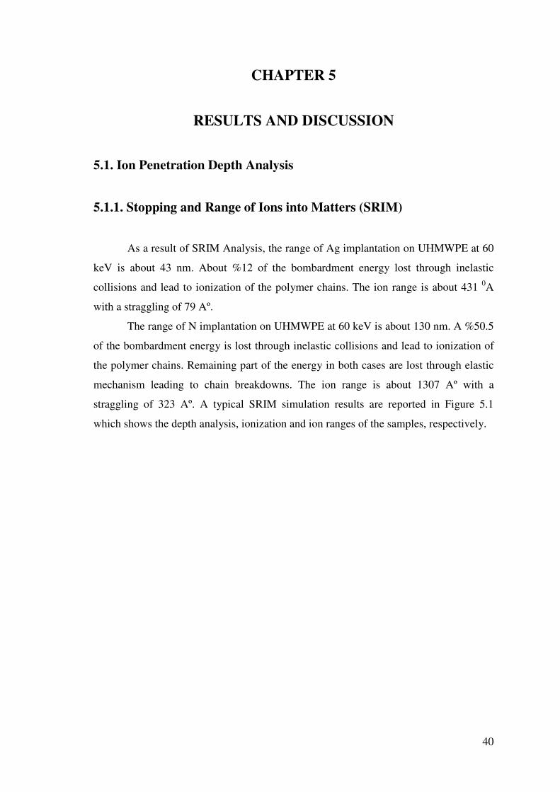
40
CHAPTER 5
RESULTS AND DISCUSSION
5.1. Ion Penetration Depth Analysis
5.1.1. Stopping and Range of Ions into Matters (SRIM)
As a result of SRIM Analysis, the range of Ag implantation on UHMWPE at 60
keV is about 43 nm. About %12 of the bombardment energy lost through inelastic
collisions and lead to ionization of the polymer chains. The ion range is about 431 0A
with a straggling of 79 Aº.
The range of N implantation on UHMWPE at 60 keV is about 130 nm. A %50.5
of the bombardment energy is lost through inelastic collisions and lead to ionization of
the polymer chains. Remaining part of the energy in both cases are lost through elastic
mechanism leading to chain breakdowns. The ion range is about 1307 Aº with a
straggling of 323 Aº. A typical SRIM simulation results are reported in Figure 5.1
which shows the depth analysis, ionization and ion ranges of the samples, respectively.
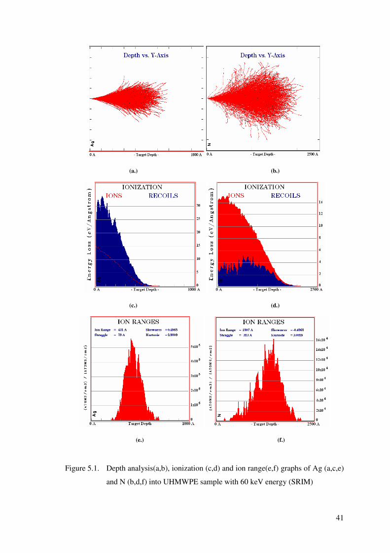
41
(a.) (b.)
(c.) (d.)
(e.) (f.)
Figure 5.1. Depth analysis(a,b), ionization (c,d) and ion range(e,f) graphs of Ag (a,c,e)
and N (b,d,f) into UHMWPE sample with 60 keV energy (SRIM)

42
5.1.2. Rutherford Back Scattering (RBS) Analysis
Rutherford back-scattering technique (RBS) is an analytical tool that uses elastic
scattering of 0.1-3 MeV charged particles to analyze the surface and the outer few
micrometers of solids. RBS system consists of an accelerator and scattering chamber
with sample manipulators and particle detectors. The number of backscattered ions is
proportional to the square of the atomic number of the target element. A model based on
the actual scattering cross section and the stopping power is used to generate a
theoretical spectra which is then adjusted until a fit is obtained to the experimental data
(Tesmer et. al 1995) .
From the RBS graph, silver (Ag) concentration on the sample surfaces was
determined . Figures 5.3 and 5.4 show the RBS Spectrum of Ag and Ag+N ion
implantion of the samples, respectively. Black line denotes RBS graph and red line
denotes RUMP simulation. Due to the RUMP simulation results, it was found that Ag
ions can be detected up to 32 +15 nm underneath the surface, and after Ag+N
implantation, Ag ions can be detected up to 42 +15 nm underneath the surface. Those
values are in good agreement with the SRIM simulation results.
In Figure 5.2 and Figure 5.3, both spectrums show an O peak which is believed
to be due to the oxidation reaction and the other small peaks are thought to be probably
due to the contamination of the vacuum gas. Turos et. al and Rizzatti et. al reported that
oxidation behaviour of UHWMPE after irradiation. Oxygen uptake takes place once the
ion bombarded polymer sample was exposed to the air and upon aging the continuous
oxygen uptake was observed (Turos et. Al. 2006, Rizzatti et. Al. 2000). Rizzatti
reported that oxygen concentration does not exceed the initial level for as implanted
samples and it extends only to the greater depth as a function of the storage time. After
two years storage the oxidized layer extends over the whole modified depth that is about
the incident ion range. Due to this, O peak that we observed probably a result of
oxidation.
Braun have reported before, on the profitable influence of surface contamination
from diffusion pump oil on tribiological properties (Braun 1988). In RBS spectrum we
have some small peaks those might be occurred due to the vacuum environment (pump
oil or vacuum gas).
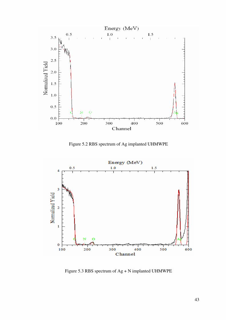
43
Figure 5.2 RBS spectrum of Ag implanted UHMWPE
Figure 5.3 RBS spectrum of Ag + N implanted UHMWPE
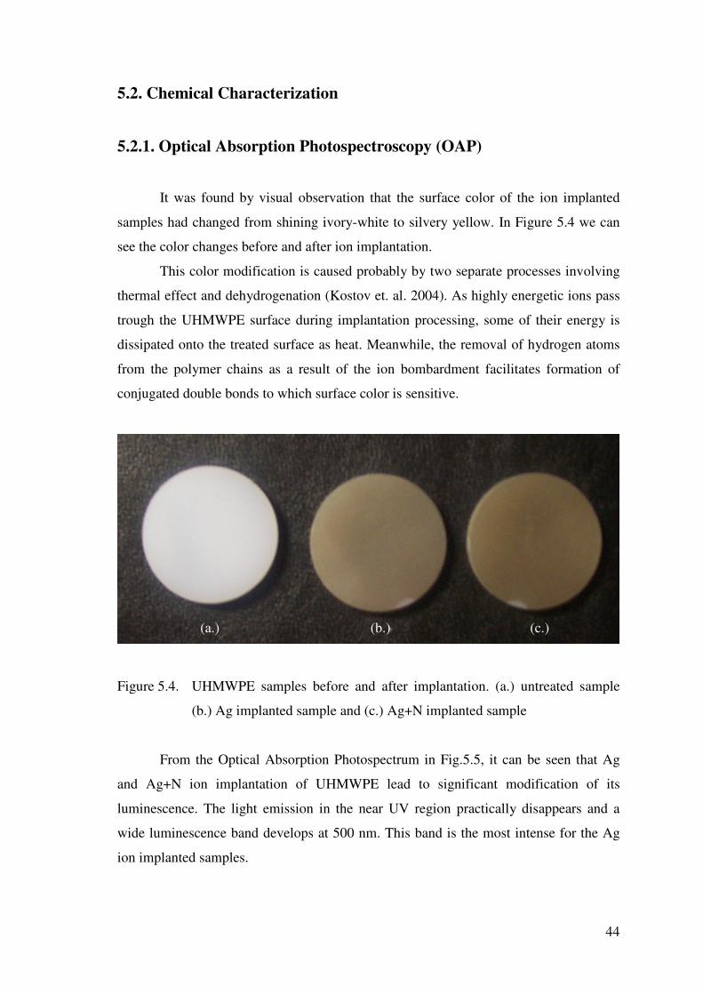
44
5.2. Chemical Characterization
5.2.1. Optical Absorption Photospectroscopy (OAP)
It was found by visual observation that the surface color of the ion implanted
samples had changed from shining ivory-white to silvery yellow. In Figure 5.4 we can
see the color changes before and after ion implantation.
This color modification is caused probably by two separate processes involving
thermal effect and dehydrogenation (Kostov et. al. 2004). As highly energetic ions pass
trough the UHMWPE surface during implantation processing, some of their energy is
dissipated onto the treated surface as heat. Meanwhile, the removal of hydrogen atoms
from the polymer chains as a result of the ion bombardment facilitates formation of
conjugated double bonds to which surface color is sensitive.
Figure 5.4. UHMWPE samples before and after implantation. (a.) untreated sample
(b.) Ag implanted sample and (c.) Ag+N implanted sample
From the Optical Absorption Photospectrum in Fig.5.5, it can be seen that Ag
and Ag+N ion implantation of UHMWPE lead to significant modification of its
luminescence. The light emission in the near UV region practically disappears and a
wide luminescence band develops at 500 nm. This band is the most intense for the Ag
ion implanted samples.
(a.)
(b.)
(c.)

45
0
0.2
0.4
0.6
0.8
1
1.2
1.4
1.6
1.8
0 500 1000 1500 2000 2500 3000 3500
Wave Lenght (nm)
Abs
orba
nce
Ag+N Implanted UHMWPE Ag Implanted UHMWPE Unimplanted UHMWPE
Figure 5.5. Optical Absorption Photospectroscopy (UV-VIS) of untreated, Ag and
Ag+N Implanted UHMWPE
Figure 5.5. exhibits an increase in optical absorption followed by a shift of the
optical absorption threshold in both Ag and Ag+N implanted samples. Rizatti et al has
observed the same behaviour with the ion bombarded poly (paraphenylene sulphide)
films and these effects associated with a decrease in the optical gap (Eg) which can be
related to a structural rearrangement of aromatic rings, possibly, generating a
continuous network of conjugated cyclic structures (Rizzatti et. al. 1995).
The optical absorption results confirmed the degradation of polymer surface and
formation an amorphous carbon layer, which becomes more diamond-like. Davenas et
al. also attributed to this to the formation of silver colloidal particles at the surface
(Davenas et. al. 2002)
5.2.2. Attenuated Total Reflectance /� Fourier Transform Infra Red
(ATR / FT-IR) Spectroscopy
The characteristic absorption bands for the CH2 bonds appear in the 2900–2840,
1460–1370 and 740–720 cm−1 regions (Evelyn at. al. 1998, Davenas et. al. 1989). The
transmission ATR analysis of the untreated and Ag and Ag+N implanted samples

46
confirms the C–H band breaking since the C–H stretching (at 2847 cm−1) band bending
peaks of the pure UHMWPE sample disappears after Ag and Ag+N implantation.
(Davenas et. al 1989, Colthup et. al. 1990, Chappa et. al. 2006, Bracco et. al. 2005).
Table 5.1 reports that wavenumber (cm−1) and vibrational modes of Ag and Ag+N
implanted UHMWPE samples.
Table 5.1. Wavenumber (cm−1) and vibrational modes of Ag and Ag+N implanted
UHMWPE
Absorption (Wavenumber in cm−1) Group
610-660 Cis CH wagging
719 C-H rocking
965 Trans CH wagging
1164 C-O-C stretching
1297 C-O stretching
1367 OH Deformation
1462 C-H bending
1594-1630 C=C stretching
1650 C=N
1738 C=O stretching
2847 C-H stretching
3300-3500 OH stretching
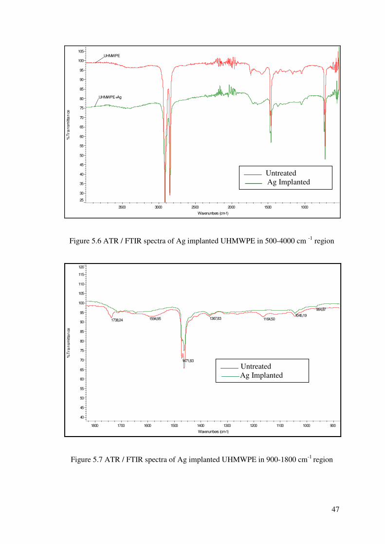
47
UHMWPE+Ag
UHMWPE
25
30
35
40
45
50
55
60
65
70
75
80
85
90
95
100
105
%Tr
an
smitt
an
ce
1000 1500 2000 2500 3000 3500
Wavenumbers (cm-1)
Figure 5.6 ATR / FTIR spectra of Ag implanted UHMWPE in 500-4000 cm -1 region
964,871045,19
1164,501367,83
1471,83
1594,951738,24
40
45
50
55
60
65
70
75
80
85
90
95
100
105
110
115
120
%T
ran
smitt
an
ce
900 1000 1100 1200 1300 1400 1500 1600 1700 1800 Wavenumbers (cm-1)
Figure 5.7 ATR / FTIR spectra of Ag implanted UHMWPE in 900-1800 cm-1 region
Untreated
Ag Implanted
Untreated
Ag Implanted

48
Ag+N
BLANK
25
30
35
40
45
50
55
60
65
70
75
80
85
90
95
100
%Tr
ans
mitt
an
ce
1000 1500 2000 2500 3000 3500
Wavenumbers (cm-1)
Figure 5.8 ATR / FTIR spectra of Ag+N implanted UHMWPE in 500-4000 cm -1 region
1164,50
1462,89
1471,83
1738,24 966,78
1045,001297,021367,87
1462,90
25
30
35
40
45
50
55
60
65
70
75
80
85
90
95
100
105
%T
ran
smitt
an
ce
1000 1100 1200 1300 1400 1500 1600 1700 Wavenumbers (cm-1)
Figure 5.9 ATR / FTIR spectra of Ag+N implanted UHMWPE in 900-1800 cm-1 region
Untreated
Ag+N Implanted
Untreated
Ag+N Implanted

49
As can be seen in Figure 5.7 and 5.9 after implantation, the increase in the
absorption bands in the 1594 and 1738,4 cm−1 regions (Table 5.1), due to the
implantation, has been attributed to the creation of unsaturated C=C bonds and a
beginning of polymer oxidation (Premnath et. al. 1999, Bracco et. al. 2006). One of the
main products of the radiation-induced chemical changes is the C=C formation, and its
stretching vibration is clearly observed in the spectra by an absorbance peak at 1594-
1630 cm−1. The presence of this peak suggests that after Ag and Ag+N implantation, the
polymer surface becomes poor of hydrogen and rich of cross-linked carbon atoms.
Furthermore, some carbonyl formation due to oxidative degradation is observed at
around 1720 cm−1.
Geometric isomerism (also known as cis/trans isomerism) is a form of
stereoisomerism (Colthup et. al. 1990). Isomers are molecules that have the same
molecular formula, but have a different arrangement of the atoms in space. That
excludes any different arrangements which are simply due to the molecule rotating as a
whole, or rotating about particular bonds. In stereoisomerism, the atoms making up the
isomers are joined up in the same order, but still manage to have a different spatial
arrangement. Geometric isomerism is one form of stereoisomerism (Colthup et. al.
1990). The trans-CH wagging absorption band appears around 965 cm−1 on the spectra
of Ag and Ag+N implanted UHMWPE. The trans-CH wagging vibration of the olefins
is relatively insensitive to mass or mesomeric effects but shows sensitivity to the
inductive power of the group (Evelyn et. al 1998). Cis-CH wagging located on 610-66
cm-1 are also present for both samples. Paticulary C-H characteristic peaks decrease
with the implantion. In both the wag vibrations, the motions of the hydrogens are
partially balanced by countermotions of the substituents. This makes the substituents
more mechanically involved in the vibrations. By this way, these vibrations become
more variable in frequency. Because of the rotational isomerism the wag band
broadened. This means that both kinds of groups will be excited at the same time, but
with various phase relationships (Evelyn et. al 1998).
In Figures, 5.8 and 5.9 at 1650 cm−1 absorptions there is significant increasing
because of the Amine groups in the Ag+N implanted samples . Amine peaks appears
not only in Ag+N Implanted samples spectra, but also in Ag Implanted ones because of
the N2 gas which was used to vent the implantation chamber.
The formation of the peak at the 3500 cm−1 region signifies the formation of NH
and OH bonds at the higher end.
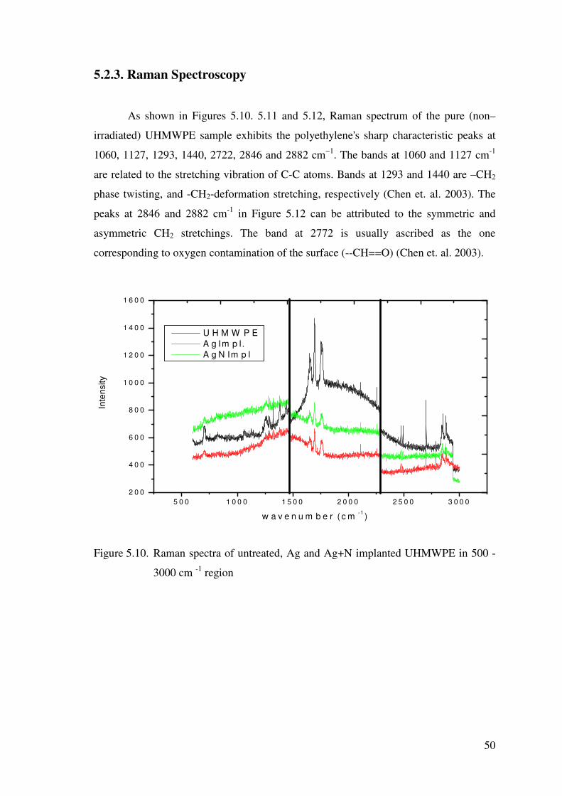
50
5.2.3. Raman Spectroscopy
As shown in Figures 5.10. 5.11 and 5.12, Raman spectrum of the pure (non–
irradiated) UHMWPE sample exhibits the polyethylene's sharp characteristic peaks at
1060, 1127, 1293, 1440, 2722, 2846 and 2882 cm−1. The bands at 1060 and 1127 cm-1
are related to the stretching vibration of C-C atoms. Bands at 1293 and 1440 are –CH2
phase twisting, and -CH2-deformation stretching, respectively (Chen et. al. 2003). The
peaks at 2846 and 2882 cm-1 in Figure 5.12 can be attributed to the symmetric and
asymmetric CH2 stretchings. The band at 2772 is usually ascribed as the one
corresponding to oxygen contamination of the surface (--CH==O) (Chen et. al. 2003).
5 0 0 1 0 0 0 1 5 0 0 2 0 0 0 2 5 0 0 3 0 0 02 0 0
4 0 0
6 0 0
8 0 0
1 0 0 0
1 2 0 0
1 4 0 0
1 6 0 0
Inte
nsity
w a v e n u m b e r ( c m -1 )
U H M W P E A g Im p l. A g N Im p l
Figure 5.10. Raman spectra of untreated, Ag and Ag+N implanted UHMWPE in 500 -
3000 cm -1 region
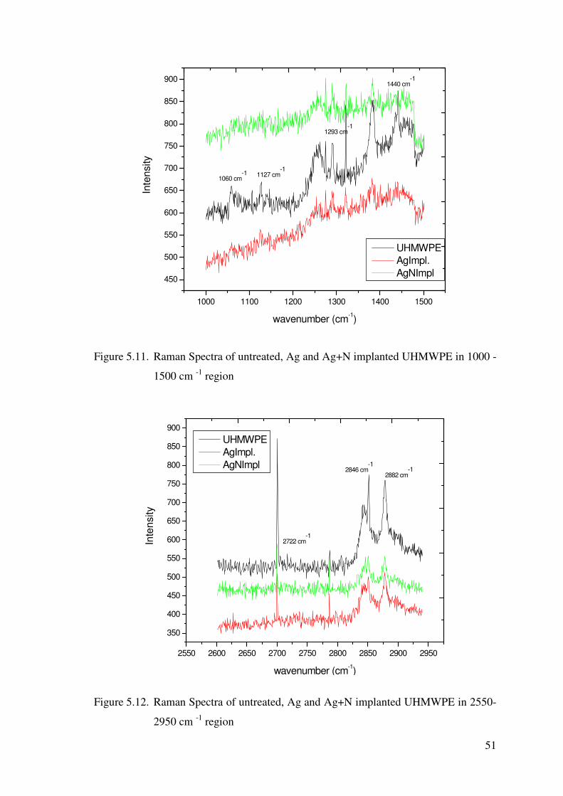
51
1000 1100 1200 1300 1400 1500
450
500
550
600
650
700
750
800
850
900
1440 cm-1
1293 cm-1
1127 cm-1
Inte
nsity
wavenumber (cm-1)
UHMWPE AgImpl. AgNImpl
1060 cm-1
Figure 5.11. Raman Spectra of untreated, Ag and Ag+N implanted UHMWPE in 1000 -
1500 cm -1 region
2550 2600 2650 2700 2750 2800 2850 2900 2950
350
400
450
500
550
600
650
700
750
800
850
900
2722 cm-1
2882 cm-12846 cm
-1
Inte
nsity
wavenumber (cm-1)
UHMWPE AgImpl. AgNImpl
Figure 5.12. Raman Spectra of untreated, Ag and Ag+N implanted UHMWPE in 2550-
2950 cm -1 region
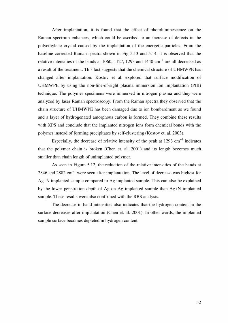
52
After implantation, it is found that the effect of photoluminescence on the
Raman spectrum enhances, which could be ascribed to an increase of defects in the
polyethylene crystal caused by the implantation of the energetic particles. From the
baseline corrected Raman spectra shown in Fig 5.13 and 5.14, it is observed that the
relative intensities of the bands at 1060, 1127, 1293 and 1440 cm−1 are all decreased as
a result of the treatment. This fact suggests that the chemical structure of UHMWPE has
changed after implantation. Kostov et al. explored that surface modification of
UHMWPE by using the non-line-of-sight plasma immersion ion implantation (PIII)
technique. The polymer specimens were immersed in nitrogen plasma and they were
analyzed by laser Raman spectroscopy. From the Raman spectra they observed that the
chain structure of UHMWPE has been damaged due to ion bombardment as we found
and a layer of hydrogenated amorphous carbon is formed. They combine these results
with XPS and conclude that the implanted nitrogen ions form chemical bonds with the
polymer instead of forming precipitates by self-clustering (Kostov et. al. 2003).
Especially, the decrease of relative intensity of the peak at 1293 cm−1 indicates
that the polymer chain is broken (Chen et. al. 2001) and its length becomes much
smaller than chain length of unimplanted polymer.
As seen in Figure 5.12, the reduction of the relative intensities of the bands at
2846 and 2882 cm−1 were seen after implantation. The level of decrease was highest for
Ag+N implanted sample compared to Ag implanted sample. This can also be explained
by the lower penetration depth of Ag on Ag implanted sample than Ag+N implanted
sample. These results were also confirmed with the RBS analysis.
The decrease in band intensities also indicates that the hydrogen content in the
surface decreases after implantation (Chen et. al. 2001). In other words, the implanted
sample surface becomes depleted in hydrogen content.
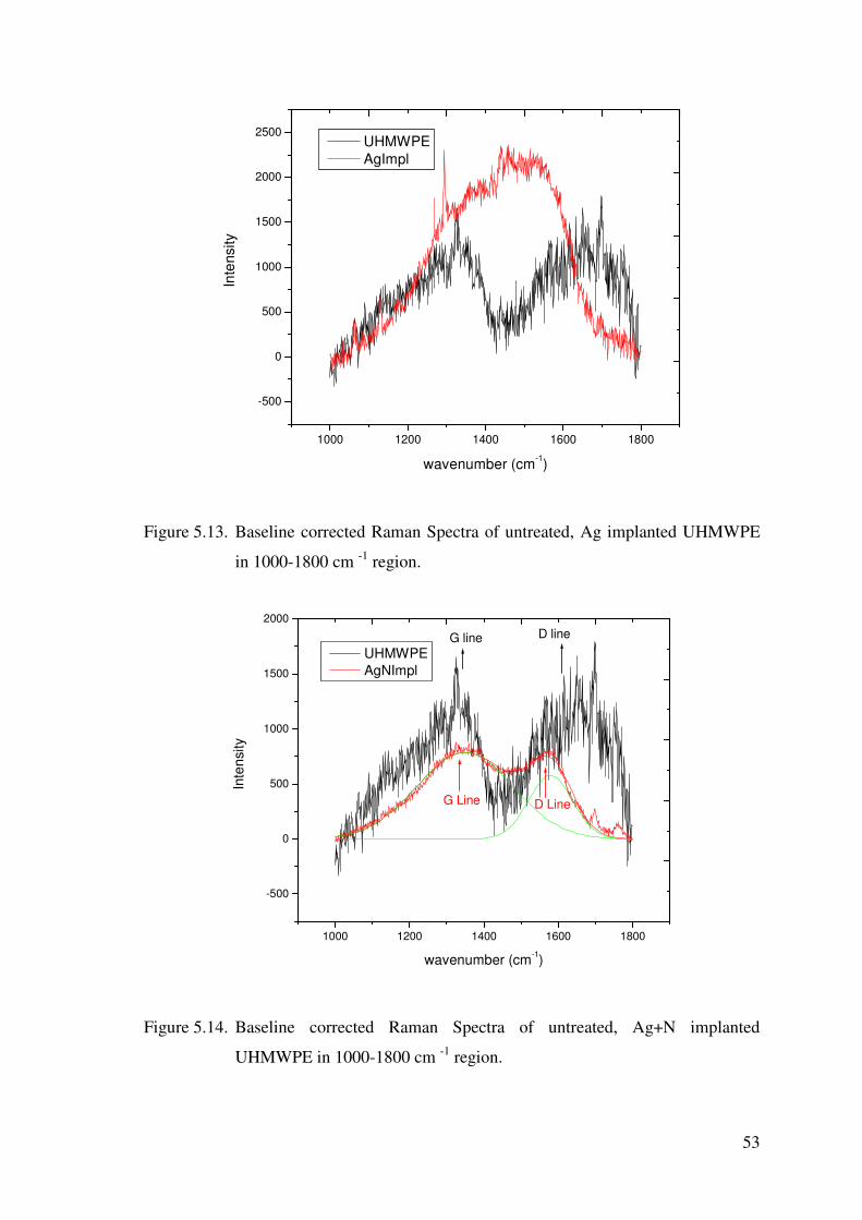
53
1000 1200 1400 1600 1800
-500
0
500
1000
1500
2000
2500
Inte
nsity
wavenumber (cm-1)
UHMWPE AgImpl
Figure 5.13. Baseline corrected Raman Spectra of untreated, Ag implanted UHMWPE
in 1000-1800 cm -1 region.
1000 1200 1400 1600 1800
-500
0
500
1000
1500
2000
G Line D Line
G line D line
Inte
nsity
wavenumber (cm-1)
UHMWPE AgNImpl
Figure 5.14. Baseline corrected Raman Spectra of untreated, Ag+N implanted
UHMWPE in 1000-1800 cm -1 region.

54
After removing for clarity the UHMWPE characteristic peaks, a broad peak with
two shoulders at approximately 1360 and 1560 cm−1 can be observed in the Raman
spectrum shown in Fig. 5.13 and 5.14. These two bands are fitted with two Gaussian
functions and can be attributed to the D and G band of hydrogenated amorphous carbon,
respectively. The two regions of interest in the Raman microprobe analysis are at 1595
cm-1 (G-line) and at 1350 cm-1 (D-line). The G-line is attributed to graphite structure
formation in the material and the D-line is attributed to amorphous structure or
"disorder" in the material (Evelyn et. al. 1998)
From the fitting, the position and full width at half maximum (FWHM) of the G
and D peaks as well as the ratio of the D to G peak area—I(D)/I(G), were determined.
Although, sp3/sp2 ratios in the hydrogenated carbon films cannot be derived directly
from the Raman spectra, some quantitative information still can be extracted because
the position of G and D lines, G peak's FWHM and the peak integral intensity ratio
I(D)/I(G) are correlated with the sp3/sp2 bonding ratio (Robertson et. al 2002). The
Raman spectrum of Ag+N implanted UHMWPE in Figure 5.15 exhibits characteristics
typical for the diamond-like carbon (DLC), including a disorder peak (D peak) at 1365
cm−1, and a graphite-like peak (G peak) at 1560 cm−1 with a I(D)/I(G) ratio of about
0.65. These observations indicate formation of DLC layer on the UHMWPE surface as
a result of ion implantation process. Davenas et. al suggest that as the irradiation energy
is lowered to 10 keV., the analysis of UV edge shows that this carbon layer becomes
more diamond-like (Davenas et. al.2002).
The properties of carbon coatings strongly depend on their microstructure,
which is commonly considered as an amorphous mixture of sp2 and sp3 hybridized
carbon atoms. The DLC characteristics can vary from those similar to graphite to those
closely approaching the features of natural diamond. So the ratio of sp3/sp2 carbon
atoms is one of the most important factors governing the quality of the DLC films. In
general, the higher this ratio is, the closer the DLC properties approach those of
diamond (Robertson et. al 2002).
A graphite-like structure shows better mechanical properties and better
biocompatibility (Valenza et. al. 2004). Davenas et. al. examined that increased
antibacterial effect resulting from colloidal silver and DLC structure on the surface layer
especially when lowering the implantation energy (Davenas et. al. 2002). In addition to
graphitization, several researchers (Guzman et. al. 2002, San et. al. 2002, Chen et. al
2000, Lee et. al. 1994) have suggested that cross-linking of polymer chains, by the

55
reaction of free radicals with ions, also strengthens the surface properties through the
formation of a three-dimensional connected network.
5.3. Thermal Characterization
5.3.1. Thermo Gravimetric Analysis (TGA)
Figure 5.15 shows TGA results of pure and implanted UHMWPE samples. It
can be seen that onset degradation for pure UHMWPE is around 251.68 ºC. The onset
degradation temperature shifted after irradiation of the samples . For Ag implanted
samples thermograms shifts to 312.69 ºC, while for Ag + N implanted samples to
267.26 ºC. The termination of degradation temperatures also increased to higher values
after Ag and Ag+N ion implantation. As seen in Figure 5.16, the same trend was
observed with termination degradation point. The termination of degradation value is
445.65 for pure UHMWPE, but this value shifted to 488.77 and 497.13 for Ag
implanted and Ag + N implanted samples, respectively.
Figure 5.15. TGA analysis of untreated, Ag and Ag+N implanted UHMWPE.
0 100 200 300 400 500 600
1
2
3
4
5
6
497.13488.77445.65
UHMWPE AgImpl AgNImpl
Wei
ght(m
g)
T(oC)
251.68
312.69
267.26

56
5.3.2. Diferential Scanning Calorimetry (DSC)
Figure 5.16 shows the DSC curves of the pure and implanted UHMWPE
samples. The DSC trace for UHMWPE shows two key features. The first feature of the
DSC curve is the peak melting temperature (Tm), which was obtained to be 141°C, and
corresponds to the point at which the majority of the crystalline regions have melted
(Kurtz 2004).
The melt temperature reflects the thickness of the crystals, as well as their
perfection. Thicker and more perfect polyethylene crystals will tend to melt at a higher
temperature than smaller crystals (Kurtz 2004).
In addition, the area underneath the melting peak is proportional to the
crystallinity of the UHMWPE. DSC provides a measure of the total heat energy per unit
mass (also referred to as the change in enthalpy, delta H) required to melt the crystalline
regions within the sample. By comparing the change in enthalpy of a UHMWPE sample
to that of a perfect 100% crystal, one can calculate the degree of crystallinity of the
UHMWPE (Kurtz 2004, Blundell et. al.1981, Gray et. al.1970).
Figure 5.16. DSC analysis of untreated, Ag and Ag+N implanted UHMWPE.
50 100 150 200 250 300 350 400
-2
0
2
4
6
8
10
Tm=140
∆Cp=0.43
∆Cp=0.51
Tm=~137
UHMWPE AgImpl AgNImpl
Hea
t Flo
w
Temperature o C
Tm= 141
∆Cp=0.37

57
As seen in Figure 5.16, DSC thermograms for untreated and ion implanted
UHMWPE exhibited one distinct peak and in addition, a small overlapping shoulder
region which can be observed between 200-300 C region. The shoulder represents �Cp
value and this value is obviously different for each sample which indicates that
polymeric chain is modified after treatment and resultant materials are different from
pure sample. The total heat of melting (fusion) �H value is slightly increasing after
implantation. Due to this, % crytallinity values increased after Ag and Ag+N
implantation. In Figure 5.16, it is obvious that after implantation % crystallinity has
increased slightly,while melting point (Tm) values slightly changes. This can be
explained by chain scission on implanted UHMWPE samples, which leads to a
reduction in the molecular weight of the material. This allows the chains to rearrange to
form crystalline regions and %crystallinity increasing while Tm decreasing after
implantation. Al-Ma’adeed et. al and Aydinli and Tincer were observed similar trend in
%crystallinity after irradiation of UHMWPE. ( Al-Ma’adeed et. al 2005, Aydinli and
Tincer 2001)
Thermal properties of the samples before and after implation were tabulated in
Table 5.2. As a result, DSC measurements have shown that polymer modification was
observed by implantation of UHMWPE samples.
Table 5.2. Thermal data of untreated Ag and Ag+N implanted UHMWPE samples
UHMWPE -����Hf (fusion)J/g Tm (C°) ����Cp
J/gK.
% Crystallinity
����Hf / 291J/g
Untreated -115,07 J/g 141 0.51 39.5
Ag Implanted -116,52 J/g 137 0.37 40
Ag+N Implanted -119,67 J/g 140 0.43 41.1
In literature a few researchers studied %crystallinity of UHMWPE. For
example, Torrisi et. al. studied thin polyethylene films, irradiated in air with 5 meV.
electron beams. To the contrary of our results, they observed that significant increasing
in melting point (Tm) for an electron dose 3.2 MGy, moreover their data indicated a
slow decrease in the polymer crystallinity and in the melting enthalpy (Torrisi et. al.
2005). On the other hand, Al-Ma’adeed et. al studied the effect of shelf aging, for up to

58
one year in air, on the properties of gamma-irradiated ultra-high molecular weight
polyethylene. This study showed that crystallinity is increased with radiation dose and
with aging ( Al-Ma’adeed et. al. 2005). Aydinli and Tincer also studied the effect of
irradiation on pure UHMWPE and they found that crystallinity increased and this
caused higher enthalpy of crystallization (Aydinli and Tincer 2001)
5.3.3. X-Ray Diffraction (XRD) Analysis
Crystallinity changes can be observed from XRD results in Figure 5.17. We
calculate the %crstallinity with XRD as the ratio of total integral intensities of
crystalline peaks (Ic) to the integral intensities of amorphous and crystalline peaks
(Ia + Ic) (Gupta et. al. 1997).
After implantation, it was found that % crystallinity in the UHMWPE increased from
30% to 40%. Table 5.3 gives the % crystallinity results obtained from XRD measurements.
Figure 5.17. XRD pattern of untreated, Ag and Ag+N implanted UHMWPE.
0 10 20 30 40 50 60 70 80
% Crystallinty= 30.5
% Crystallinty= 40.2
UHMWPE AgImpl AgNImpl
Inte
nsity
2*theta
% Crystallinty= 40.3

59
The XRD and DSC analysis reveal an increase in the main diffraction peak area and in
the endothermic peak area, respectively, confirming a gradual increasing in the
crystallinity after Ag and Ag+N implantation, respectively. Costa et. al and Joo et al.
also observed this result (Costa et. al 2001, Joo et. al. 2000).
Table 5.3. % Crystallinty of untreated Ag and Ag+N implanted UHMWPE samples
calculated by XRD
UHMWPE % Crystallinity
Untreated 30.5
Ag Impl. 40.2
Ag+N Impl. 40.3
Evidently, either Ag or Ag+N ion implantation of UHMWPE led to increase in
% crystallinity compared to untreated sample. As reported previously by a few
researchers (Al’Maaded et al 2005, Bracco et. al. 2005), this reason might be due to the
oxidation after ion implantation. After ion implantation, because of the higher oxygen
permeability, oxygen can enter the polymer material more readily, thereby causing
greater oxidation in the presence of irradiation induced free radicals. Oxygen will react
with free radicals in the polymer causing further chain scission. As a consequence, the
crystallinity of UHMWPE increases as the scission of tie molecules led to reduced
molecular weight, which in turn permits polymer chain in non-crystalline regions of the
polymer to fold and crystallize, as well as to allow increasing perfection of existing
folded-chain crystallites.
5.4. Surface Properties and Morphology
5.4.1. Scanning Electron Microscopy (SEM) and Optical Microscopy
(OM)
Surface properties of pure UHMWPE and Ag and Ag+N implanted UHMWPE
samples were investigated by SEM. Optical Microscope (OM) analysis was also used in
combination with SEM Analysis. Figure 5.18-a,b,c shows the SEM micrographs and

60
Figure 5.18 (d,e,f) shows the Optical Microscope micrographs of the sample surfaces.
The optical microscopy pictures of the samples showed that (Fig 5.18 – d,e,f), ion
distribution on Ag implanted surfaces (5.18.e) was more homogenous in comparison to
the Ag+N implanted surface (5.18. d).
SEM micrographs in Figure 5.18 (a,b,c) were obtained randomly with several
measurements. Results repsesent the surface morphology before and after implantation.
Under a very high magnification, nano-crack arrays were found (Fig. 5.19 a,b,c). Shi et.
al have observed some microcracks on UHMWPE surface and attributed stress-induced
preferential orientation of the crystalline lamellae in the UHMWPE led to the origin of
ripples containing micro-cracks (Shi et. al. 2000). As seen in Figure 5.18, the cracks on
the pure UMMWPE surface are easily visible and can be about 100 nm. long and 10
nm. wide. However, at the same magnifications, after implantation of UHMWPE, the
cracks are much more smaller and significantly disappears. Especially on Ag implanted
samples, cracks are almost disappeared.
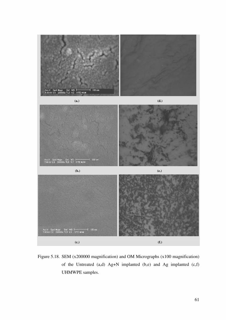
61
(a.) (d.)
(b.) (e.)
(c.) (f.)
Figure 5.18. SEM (x200000 magnification) and OM Micrographs (x100 magnification)
of the Untreated (a,d) Ag+N implanted (b,e) and Ag implanted (c,f)
UHMWPE samples.

62
5.4.2. Hardness
Table 5.4 shows the relative shore hardness values for pure UHMWPE and Ag
and Ag+N implanted UHMWPE samples measured four times. An increase in
microhardness values with respect to pure UHMWPE has been measured after
implantation. Particularly, the hardness value of Ag implanted sample is almost % 13
higher and Ag+N implanted one % 8 higher with respect to untreated UHMWPE .
Shirong Ge et al. ound an increase in the hardness measurements after N
implantation with respect to the pure UHMWPE. Valenza et.al also showed that after
Xe ion implantion to UHMWPE, an increase of the surface microhardness with respect
to pure UHMWPE was measured, particularly in the sample implanted at 3x10¹⁵ Xe+
/cm2, the microhardness was about 30 % higher with respect to that of pristine
UHMWPE sample (Valenza et. al. 2004).
Table 5.4. Shore-D hardness values of untreated. Ag implanted and Ag+N implanted
UHMWPE.
Untreated
UHMWPE (Shore D)
Ag implanted
UHMWPE (Shore D)
Ag+N implanted
UHMWPE (Shore D)
58,2 65,9 62,8
58,6 67,1 64,2
58,7 66,2 63,2
58,5 66,4 63,4
Average= 58,5 average= 66,4 average= 63,4
From the FT-IR and Raman Spectroscopy measurements, we found that after
implantation crosslinking and high carbon concentration occur on the surface of
UHMWPE, therefore we expect an increase in the hardness values after implantation on
the surface. Many researchers also reported that an increase in hardness is due to the
crosslink formation on the surface (Robertson 2002, Liu et. al. 1996, San et. al. 2001,
Rao et. al. 1995) and network structure in molecular chains (Allen et. al. 1996).
An increase in hardness is due to the increase in crystallinity and the breakage of
the long chains of the polymer, increasing brittleness and weakening the material

63
(Robertson 2002). The increase in hardness occurs because the precipitates restrict the
motion of dislocations near the surface.
The observed improvements in the hardness and morphologic properties can be
attributed to graphitization on the surfaces of the samples induced by ion bombardment.
A graphite-like structure shows better mechanical properties and better biocompatibility
(Valenza et. al. 2004). In addition to graphitization, many researchers (Guzman et. al
2002, San et. al. 2002, Chen et. al. 2000, Lee et. al. 1994) have suggested that cross-
linking of polymer chains, by the reaction of free radicals with ions, also strengthens the
surface properties through the formation of a three-dimensional connected network.
5.4.3. Wettability
Generally, polymers are hydrophobic, and conversion of these polymers from
being hydrophobic to hydrophilic usually improves the adhesion strength,
biocompatibility, and other pertinent properties. Formation of oxygen functionalities by
ion implantation is one of the most useful and effective processes of surface
modification (Kurtz 2004).
The improved wettability of UHMWPE contributes specifically to lower friction
than the other materials articulated against UHMWPE under physiologic loading and
lubrication conditions. It is also proved that the improved wettability on the implanted
UHMWPE surface increases its blood compatibility on the friction area. Surface
wettability was measured before and after implantation of the UHMWPE samples using
both water and simulated body fluid (SBF) as wetting liquids in the experiments. The
mean contact angles of the samples measured on both unimplanted (pure) and
UHMWPE and Ag and Ag+ N implanted UHMWPE surfaces are shown in Table 5.5.
Table 5.5. Mean Contact Angle Values of untreated, Ag implanted and Ag+N
implanted UHMWPE.
Contact Angle (°) Untreated
UHMWPE
Ag Implanted
UHMWPE
Ag+N Implanted
UHMWPE
Water 56.2 ° 44.8 ° 32 °
SBF 49.4 ° 34 ° 24.6 °

64
The water wetting and SBF wetting surface measurements indicated that the
wetting angle decrease with the implantation, from about 56.2 o for pure UHMWPE to
the value of 44.8 o for Ag implanted and 32 o for Ag+N implanted sample, respectively
when the water is used as wetting liquid. The results implies that the wettability of
UHMWPE is improved as a result of either Ag or Ag+N implantation treatment.
Among the implanted samples, Ag+N implanted sample shows the best wetting ability.
According to Table 5.5, the results also suggest that SBF wetting ability is better than
water.
Several researches reported that ion implantation increases the wettability of
polymers (Lewis 2001, Shirong et. al. 2003, Bracco et. al. 2006). For example Shirong
et al. (Shirong et. al. 2003) reported that wettability improvement with N implantation.
Torrisi et.al have found that with Xe implantation of UHMWPE surface, the wettability
of the surface was improved, but they reported that bovine serum album wetting ability
is lower with respect to water (Torrisi et. al 2006) .
5.4.4. Atomic Force Microscopy (AFM)
Figure 5.19 shows the surface topography of pure and implanted UHMWPE
samples. As seen from the figure, the surface roughness of the UHMWPE surface
decreases from 121.35 Ra (nm.) for pure polymer to 62.632 Ra (nm), 106.94 Ra (nm)
for Ag and Ag+ N implantes samples, respectively. This shows that Ag and Ag+N
implantation improves surface smoothness . It was reported that rough surfaces caused
more wear debris (Lewis 2001, Gispert et. al 2006), therefore it is expected to have less
wear debris after implantation of UHMWPE surfaces. The surface wettability results are
in good agreement with the surface rougness results obtained by AFM. Better
wettability was obtained by a decrease in surface roughness of the UHMWPE after
implantation. Particularly Ag implanted sample shows smoother surfaces with respected
to Ag+ N implanted one. The wettability or adhesion is also an important aspect to
quarantee the wear resistance improvement. The wear mechanism is mainly related to
the polymer structure and particularly with the crystallinity % and cross-linking. If the
polymer has a higher crystallinity or crosslinked, the macromolecular chains are locked,
their orientation are responsible for wear debris and inhibits the wear debris. With the
result of DSC and XRD analysis, we observed increasing in % crystallinity after Ag and

65
Ag+N implantation and therefore it is expected to have better wear resistance after
implantation of UHMWPE.
Table 5.6. Roughness data of untreated, Ag implanted and Ag+N implanted UHMWPE
obtained from AFM measurements.
Untreated
UHMWPE
Ag Implanted
UHMWPE
Ag+N Implanted
UHMWPE
Rms(nm) Ra(nm) Rms(nm) Ra (nm) Rms (nm) Ra (nm)
Surface
Roughness
159.11 124.05 38.46 30.20 94.50 74.70

66
(a.)
(b.)
(c.)
Figure 5.19 3D AFM micrographs of untreated (a.), Ag implanted (b.) and Ag+N
implanted (c.) UHMWPE.

67
CHAPTER 6
CONCLUSION AND FUTURE STUDIES
In summary, usually there are two ways in modifying the structure, composition
and properties of surface of materials when using energetic ions irradiation. One is the
introduction of ions species (doping or chemical effect), the other is irradiation-induced
defect (radiation or defect effect). In this work, Ag and Ag + N hybrid ion implantation
of UHMWPE surfaces using metal-gas co-implantation technique were performed. The
effect of implantation on the chemical, structural, thermal and surface properties of
UHMWPE were investigated.
The radiation effect originates from the momentum transfer to the target (nuclear
stopping) and the exciting the electric system of the target (electric stopping) when
energetic ions pass through a polymeric material. RBS analysis shows that, Ag ions can
be detected up to 32 +15 nm underneath the surface after Ag implantation, and 42 +15
nm underneath the surface after Ag+N implantation. Those values are in
correspondence with SRIM analysis.
The optical absorption photospectroscopy exhibit an increase in optical
absorption followed by a shift of the optical absorption threshold in both Ag and Ag+N
implanted samples. From the ATR/ FTIR, it was found that cis- & trans- geometric
isomerism occured and C-H bond concentration decreased after Ag and Ag+N
implantation, which is believed to be caused by crosslink formation on the surface. C�N
band was also observed after Ag+N implantion of the sample.
Raman spectra suggests that the chemical structure of UHMWPE has changed
after implantation. Especially, the decrease of relative intensity of the peak at 1293 cm−1
indicates that the polymer chain is broken and its length becomes much smaller than the
chain length of the unimplanted polymer. The irradiation processes mainly induce bond
breakage or chain-scission by displacing atoms from polymer chain, producing recoil
atoms and molecular scission products.
Free radicals formation leads to the subsequent surface and subsurface oxidative
degradation of the virgin component. Surface oxidative degradation results from the
interaction of oxygen from the atmosphere with the long-lived free radicals. Subsurface
oxidative degradation is a consequence of the reaction of these radicals and the oxygen

68
that has diffused into and dissolved in the polymer. Free radicals are able to recombine
rather than react with oxygen, leading to increased cross-linking. It is stated that this
increased cross-linking tends to lead to a higher molecular weight because the chain is
longer, thus there is a greater probability that a carbon atom will produce a secondary
branch to begin another chain. Ion implantation states that increased cross-linking tends
to an increase in wear resistance and will enhance other mechanical properties.
In TGA and DSC analyses, the results can be attributed to the ion bombardment
inducing % crystallinity increase after implantation . It is also seen that Tm, Cp and
Hm values are changed. The crystallinity results obtained by XRD are in good
agreement with the DSC results.
The enhancement of radiation effect also leads to the formation of more active
chemical bonds that connect with each other and the degree of cross-linking increases.
Further increasing the fluence the randomly three-dimensional hydrogenated carbon
network is formed finally. The increase of the degree of cross-linking and final
formation of hydrogenated amorphous carbon network should be responsible for the
increase of hardness and wettability. The effects of the mechanism can be clearly
observed from the SEM and AFM results. Roughness is decreased after both Ag and
Ag+N implantations, respectively.
In conclusion, after Ag and Ag+N ion implantation of UHMWPE we observe
that, breaking off bonds and formation of free radicals on the surface. The processes of
cross-linking are favored by the free radical presence. It is also observed that increase in
crystallinity and thermal stability. Due to this structural modification, crack formation
reduced on the surface. Thefore, the hardness of the surface increased which caused an
improvement in wettability and roughness on the surface. Hardness and roughness were
improved better after Ag implantation, while better wettability was observed after
Ag+N implantation.
For future studies, considering biomedical application, antibacterial tests could
be performed. It is clear from the preceding discussion that significant improvement of
wear resistance of UHMWPE is expected. From this point, near future studies should be
on wear and mechanical properties of the material. However, it should be indicated that
the present wear test results may not immediately be applicable to total joint
replacements since the test configuration (pin-on-disc), type of motion (unidirectional)
and lubricant (water) employed in the present study differ from those in human joints.
However, some investigators have indicated that the simple tests can give a reasonable

69
simulation of contact conditions, and can serve as a first resort for screening surface
treatment parameters. With a view to providing firm technological database for
prolonging the lifetime of total joint replacement prostheses via surface engineering of
the articulating surfaces, long-term simulator tests with bovine serum and protein
containing fluid are planned.
70
REFERENCES
Allen C., Bloyce A. and Bell T., 1996, “Sliding wear behaviour of ion implanted ultra high molecular weight polyethylene against a surface modified titanium alloy Ti-6Al-4V”, Tribology International, Vol 29, Issue 6, pp. 527-534
Al-Ma’adeed M. A., Al-Qaradawi I. Y., Madi N. and Al-Thani N.J., 2006, The effect of
gamma irradiation and shelf aging in air on the oxidation of ultra-high molecular weight polyethylene, Applied Surface Science, Volume 252, Issue 9, pp. 3316-3322
Anders A., 2000, Handbook of Plasma Immersion Ion Implantation & Deposition,
Wiley Aydinli B. and Tincer T., 2001, Radiation grafting of various water-soluble monomers
on ultra-high molecular weight polyethylene powder. Part II: Thermal, FTIR and morphological characterization, Radiation Physics and Chemistry, Volume 62, Issue 4, pp 337-343
Barradas N.P., 2001, “Rutherford backscattering analysis of thin films and superlattices
with roughness”, J. Phys. D: Appl. Phys., Vol. 34, pp. 2109-2116 BDM Federal Inc., Ion Beam Processing Technologies, Research Report, 1996. Bertóti I., Mohai M., Tóth A. and Ujvári T., 2006, “Nitrogen-PBII modification of ultra-
high molecular weight polyethylene: Composition, structure and nanomechanical properties”, Surface and Coatings Technology
Black J., Hastings, G., 1998, Handbook of Biomaterial Properties,: Chapman & Hall, Blundell DJ, Beckett DR and Willcocks PH, 1981, “Routine crystallinity measurements
of polymers by d.s.c”, Polymer, Vol 22, pp. 704–707. Bracco P, Brunella V, Luda MP, Zanetti M and Costa L, 2005, “Radiation-induced
crosslinking of UHMWPE in the presence of co-agents: chemical and mechanical characterization”, Polymer, Vol 46, Issue 24, pp. 10648-10657
Bracco P, Brach del Prever EM, Cannas M, Luda MD and Costa L, 2006, “Oxidation
behaviour in prosthetic UHMWPE components sterilised with high energy radiation in a low-oxygen environment”, Polymer Degradation and Stability, Vol 91, Issue 9, pp. 2030-2038
Braun M., 1988, “Ion bombardment as a tool to modify surface properties of different
materials”, Vacuum, Vol 38, Issue 11, pp. 973-977 Brown I. G., Liu F., Monteiro O.R., Yu K.M., Evans P.J., Dytlewski N., Oztarhan A.,
Corcoran S.G. and Crowson D., 1998, “Synthesis of sub-surface oxide layers by hybrid metal–gas co-implantation into metals”, Surface and Coatings Technology, Vol 103-104, pp. 293-298

71
Budzynski P., Youssef A.A.and Sielanko J., 2006, Surface modification of Ti–6Al–4V alloy by nitrogen ion implantation, Wear, Vol 261, Issues 11-12, pp. 1271-1276
Callister W.D., 2003, Materials Science and Engineering: An Introduction, 6th Edition,
Wiley Chappa VC, Del Grosso MF, García-Bermúdez G. and Mazzei RO, 2006, “Infrared
spectroscopy analysis of physico-chemical modifications induced by heavy ions in ultra-high molecular weight polyethylene”, Nucl. Instr. and Meth. B, Vol 243, Issue 1, pp. 58-62
Chen J., Zhu F., Pan H., Cao J., Zhu D., Xu H., Cai Q., Shen J., Chen L. and He Z.,
2000, “Surface modification of ion implanted ultra high molecular weight polyethylene”, Nucl. Instr. and Methods B, Vol 169, Issues 1-4, pp. 26-30
Cheng Y. and Zheng Y.F., 2006, Surface characterization and electrochemical studies of
biomedical NiTi alloy coated with TiN by PIIID, Materials Science and Engineering: A, Vol 438-440, 25 November 2006, pp 146-1149
Chen J.S., Lau S.P., Sun Z., Tay B. K., Yu G. Q., Zhu F.Y., Zhu D.Z. and Xu H.J.,
2001, “Structural and mechanical properties of nitrogen ion implanted ultra high molecular weight polyethylene”, Surface and Coatings Technology, Vol 138, Issue 1, pp. 33-38
Chen J.S, Zhu FY, Pan HC, Cao JQ, Zhu DZ, Xu HJ, Cai Q, Shen J, Chen LH and He
ZR, 2000, “Surface modification of ion implanted ultra high molecular weight polyethylene”, Nucl. Instrum. Meth. B, Vol. 169, p. 26.
Chu P.K., Chen J. Y.,Wang L. and Huang N., 2002, “Plasma-surface modification of
biomaterials”, Materials Science and Engineering: R: Reports, Vol. 36, Issues 5-6, pp 143-206
Colthup N. B., Daly L.H., Wiberley S.E., Introduction to Infrared and Raman
Spectroscopy, 3.rd Edition, 1990, p.255-384 Dangsheng X., Zhan G. and Zhongmin J., 2006, “Friction and wear properties of
UHMWPE against ion implanted titanium alloy”, Surface and Coatings Technology, Article in Press, Available online 24 October 2006
Davenas J and Xu XL., 1989, “Relation between structure and electronic properties of
ion irradiated polymers”, Nucl. Instr. and Meth. B, Vol. 39, p. 754. Davenas J., Thevenard P., Phillippe F., Arnaud M.N., 2002, “Surface implantation
treatments to prevent infection complications in short term devices”, Biomolecular Engineering, Vol. 19, p. 263—268
Dong H., Bell T., Blawert C. and Mordike B.L., 2000, J. Mater. Sci. Lett., Vol 19, p.
1147.

72
Dong H., 2004, Trans. Nonferr. Met. Soc. China, Vol. 14, p. 36. Dong H. and Bell T., 2000, Wear, Vol 238, Issue 2, pp. 131-137 Doolittle L.R., 1985, “Algorithms for the rapid simulation of Rutherford backscattering
spectra”, Nucl. Instr. and Meth. B, Vol. 9, p. 344. Dumbleton J.H., 1978, “Wear and its measurement for joint prosthesis materials”,
Wear, Vol 49, Issue 2, pp. 297-326 Dumbleton J.H., Tribology of natural and artificial joints, Elsevier, New York-
Amsterdam (1980) 460 pp Dumbleton JH, Manley MT, Edidin AA., 2002, “ Is there a UHMWPE wear rate
threshold for the development of osteolysis at the hip? A review of the literature.”, J Arthroplasty 2002
Edidin AA, Kurtz SM., 2000, “ The influence of mechanical behavior on the wear of
four clinically relevant polymeric biomaterials in a hip simulator.”, J. Arthroplasty, Vol. 15, pp. 321-331.
Evelyn AL, Ila D, Zimmerman RL, Bhat K, Poker DB and Hensley, 1998, “Effects of
MeV ions on PE and PVDC”, Nucl. Instr. and Meth. B, Vol 141, Issues 1-4, pp. 164-168
Feng Q.L., Kim T.N., Wu J., Park E.S., Kim J.O., Lim D.Y. and Cui F. Z., 1998,
Antibacterial effects of Ag-HAp thin films on alumina substrates, Thin Solid Films, Vol 335, Issues 1-2, pp 214-219
Ferber H, Hofiund G.B., Mount C.K. and Hoshino S., 1991, Modification of amorphous bright chromium deposited (ABCD) films by nitrogen ion implantation, Nucl. Instrum. Methods Phys. Res., B Beam Interact. Mater. Atoms Vol. 59–60, pp. 957.
Fischer G., Welsh G.E., Kim M.C. and Schieman R.D., 1991, Effects of nitrogen ion implantation on tribological properties of metallic surfaces, Wear, Vol 146, pp. 1.
Gispert MP, Serro, Colaço R. and Saramago B, 2006, “Friction and wear mechanisms in
hip prosthesis: Comparison of joint materials behaviour in several lubricants”, Wear, Vol 260, Issues 1-2, pp. 149-158
Goldring SR, Jasty M, Roueke CM, Bringhurst FR, Harris WH., 1986, “ Formation of a
Synovial-Like Membrane at the Bone-Cement Interface. Its Role in Bone Resorption and Implant Loosening after Total Hip Replacement.”, Arthritis and Rheumatism, Vol 29, pp. 836-842.
Gray AP, 1970, “Polymer crystallinity determinations by DSC”, Thermochim Acta Vol.
1, pp. 563–579

73
Griffith MJ, Seidenstein MK, Williams D, Charnley J., 1978, “ Socket wear in Charnley low friction arthroplasty of the hip.” Clin Orthop, pp.37-47.
Gupta V.P. and Kothari V.K., 1997, Manufactured Fiber Technology, Chapman &
Hall., p. 225 Gushenets V.I., Nikolaev A.G., Oks E.M., Vintizenko L.G., Yushkov G.Y., Oztarhan
A., Brown I.G., 2006, Simple and Inexpensive Time-of-flight Charge-to-mass analyzerfor ion beam source characterization, Review of Scientific Instruments, Vol.77, pp 063301
Guzman L, Man BY, Miotello A, Adami M and Ossi PM, 2002, “Ion beam induced
enhanced adhesion of Au films deposited on polytetrafluoroethylene”, Thin Solid Films, Vol. 420–421, p. 565.
Hall RM, Siney P, Unsworth A, Wroblewski BM., 1997, “ The effect of surface
topography of retrieved femoral heads on the wear of UHMWPE sockets.”, Med Eng Phys, Vol. 19, pp. 711- 719.
Isaac GH, Dowson D, Wroblewski BM., 1996, “ An investigation into the origins of
time-dependent variation in penetration rates with Charnley acetabular cups--wear, creep or degradation?”, Proc Inst Mech Eng [H], Vol 210, pp. 209-16.
Isaac GH, Wroblewski BM, Atkinson JR, Dowson D., 1992, “ A tribological study of
retrieved hip prostheses.” Clin Orthop, pp. 115-25 Joo YL, Han OH, Lee HK and Song JK, 2000, “Characterization of ultra high molecular
weight polyethyelene nascent reactor powders by X-ray diffraction and solid state NMR”, Polymer, Vol 41, Issue 4, pp. 1355-1368
Keith K. Wannomae BS, Shayan Bhattacharyya BS, Andrew Freiberg MD, Daniel
Estok MD, William H. Harris MD and Orhun Muratoglu PhD, 2006, “In Vivo Oxidation of Retrieved Cross-linked Ultra–High-Molecular-Weight Polyethylene Acetabular Components with Residual Free Radicals”, The Journal of Arthroplasty, Vol 21, Issue 7, pp. 1005-1011
Kim Y., Lee Y., Han S. and Kim KJ, 2006, “Improvement of hydrophobic properties of
polymer surfaces by plasma source ion implantation”, Surface and Coatings Technology, Vol 200, Issues 16-17, pp. 4763-4769
Kondyurin A., Karmanov V. and Guenzel R., 2002, “Plasma immersion ion
implantation of polyethylene”, Vacuum, Vol 64, Issue 2, p. 105 Kostov K. G., Ueda M., Tan I.H., Leite N.F., Beloto A.F. and Gomes G.F., 2004,
“Structural effect of nitrogen plasma-based ion implantation on ultra-high molecular weight polyethylene”, Surface and Coatings Technology, Vol 186, Issues 1-2, pp. 287-290
Kurtz, S.M., 2004, The UHMWPE Handbook: Principles and Clinical Applications in
Total Joint Replacement, Elsevier Academic Press.
74
Lee EH, Rao GR, Lewis MB and Manur LK, 1994, Vacuum, Vol. 9, p. 1043. Lewis G., 2001, “Properties of crosslinked ultra-high-molecular-weight polyethylene”,
Biomaterials, Vol 22, Issue 4, pp 371-401 Liu J W, Yang S, Li C and Sun Y., 1996, “Friction and wear behaviors of nitrogen ion-
implanted polyimide against steel”, Wear, Vol. 194, pp. 103–106. Marcondes R., Ueda M., Kostov K.G., Beloto A.F., Leite N.F., Gomes G.F. and
Lepienski C.M., 2004, Braz. J. Phys., Vol. 34, p. 1667 Mc Kellop H., Rostlund T., Bradley G., 1993, “Evaluation of wear in an all-polymer
total knee replacement. Part 1: Laboratory testing of polyethylene on polyacetal bearing surfaces”, Clinical Materials, Vol 14, Issue 2, pp. 117-126.
McKellop H, Shen F W, Lu B, Campbell P and Salovey R, 1999, “Development of an
extremely wear-resistant ultra-high molecular weight polyethylene for total hip replacements”, J. Orthop. Res., Vol. 17, pp. 157-67
Muratoglu OK, Kurtz SM., Alternative bearing surfaces in hip replacement. In Hip
Replacement: Current Trends and Controversies. Eds. R. Sinha. New York: Marcel Dekker, 2002.
Oks E. M., Yushkov G. Yu., Evans P.J., Oztarhan A., Brown I.G., Dickinson M.R., Liu
F., MacGill R.A., Monteiro O.R. and Wang Z., 1997, “Hybrid gas-metal co-implantation with a modified vacuum arc ion source”, Nucl. Instr. and Meth. B, Vols 127-128, pp. 782-786
Öztarhan A., Brown I., Bakkaloglu C., Watt G., Evans P., Oks E., Nikolaev A. and Tek
Z., 2005, “Metal vapour vacuum arc ion implantation facility in Turkey”, Surface and Coatings Technology, Vol 196, Issues 1-3, pp. 327-332
Öztürk O, Onmu� O and Williamson D.L., 2005, Microstructural, mechanical, and
corrosion characterization of nitrogen-implanted plastic injection mould steel, Surface and Coatings Technology, Volume 196, Issues 1-3, 22 June 2005, pp 333-340
Premnath V., Bellare A., Merrill E. W., Jasty M. and Harris W. H., 1999, “Molecular
rearrangements in ultra high molecular weight polyethylene after irradiation and long-term storage in air”, Polymer, Vol 40, Issue 9, pp. 2215-2229
Qureshi A., Rakshit A.K, Singh E, Ayasthi D.K. Ganesan V. 2005, Ion Beam
Modification of Nickel Dimethylglyoxime Dispersed Polymer Films, 14th International Conference on Surface Modification of Materials by Ion Beams
Rao GR, Blau PJ and Lee. EH, 1995, “Friction microprobe studies of ion implanted
polymer surfaces”, Wear, Vol 184, pp. 213–222.
75
Rizzatti MR, Araújo MA and Livi RP., 2000, “Chemical damage and aging of ion bombarded PPS”, Nucl. Instr. and Meth. B, Vol. 170, p. 62.
Rizzatti M, Araújo MA and Livi RP, 1995, “Bulk and surface modifications of
insulating poly (paraphenylene sulphide) films by ion bombardment ”, Surf. Coat. Technol. B, Vol. 70, p. 197.
Rizzatti MR, Araújo MA and Livi RP, 2001, “The fluence effect of Ar++ bombardment
in PPS”, Nucl. Instr. and Meth. B, Vol 174, Issue 4, pp. 475-481 Robertson J., 2002, “Diamond-like amorphous carbon”, Mat. Sci. Eng., R Rep. Vol. 37,
Issue 4-6, p. 129 Rodriquez M, Medrano A., Garcia J.A., 2005, The development of competitive
applications of ion implantation treatments, 14th International Conference on Surface Modification of Materials by Ion Beams
San J, Liu J, Zhu B, Liu Z, Dong C and Zhang Q., 2001, “Tribological properties of ion-
implanted polyphenylene oxide (PPO)”, Wear, Vol. 251, Issue 1-12, pp. 1504-1510
San JF, Liu JJ, Zhu BL, Mo ZS and Zhang QY, 2002, “Metal-ion implantation effects
on nano-hardness and tribological properties of Nylon6”, Surf. Coat. Technol., Vol. 161, p. 1
Sheeja D., Tay B. K. and Nung L. N., 2005, “Tribological characterization of surface
modified UHMWPE against DLC-coated Co–Cr–Mo”, Surface and Coatings Technology, Vol 190, Issues 2-3, pp. 231-237
Shi W., Li X.Y. and Dong H., 2001, “Improved wear resistance of ultra-high molecular
weight polyethylene by plasma immersion ion implantation”, Wear, Vol 250, Issues 1-12, pp. 544-552
Shi W, Dong H and Bell T, 2000, “Tribological behaviour and microscopic wear
mechanisms of UHMWPE sliding against thermal oxidation-treated Ti6Al4V”, Materials Science and Engineering A, Vol 291, Issues 1-2, pp. 27-36
Shirong G., Wang Q., Zhang D., Zhu H., Xiong D., Huang C. and Huang X., 2003,
“Friction and wear behavior of nitrogen ion implanted UHMWPE against ZrO2 ceramic”, Wear, Vol 255, Issues 7-12, pp. 1069-1075
Sze J.Y. and Tay B.K., 2006, “Carbon ion implantation of ultra-high molecular weight
polyethylene using filtered cathodic vacuum arc with substrate pulse biasing”, Surface and Coatings Technology, Vol 200, Issues 12-13, pp 4104-4110
Tesmer J. R. and Nastasi M., 1995, Handbook of Modern Ion Beam Materials Analysis,
MRS Pittsburg
76
Torrisi L, Ilacqua A, Caridi F, Campo N, Picciotto A, Barnà R, De Pasquale D, Trimarchi M., Trifirò A. and Auditore L., 2006, “Measurements of gas diffusion in polyethylene irradiated by 5 MeV electron beams”, Radiation Effects & Defects in Solids, Vol. 161, No. 1, pp. 3–13
Turos A., Abdul-Kader AM, Grambole D, Jagielski J, Pitkowska A, Madi NK and Al-
Maadeed M, 2006, “The effects of ion bombardment of ultra-high molecular weight polyethylene”, Nucl. Instr. and Meth. B, Vol. 249, Issues 1-2, pp. 660-664
Valenza A., Visco A.M., Torrisi L. and Campo N., 2004, “Characterization of ultra-
high-molecular-weight polyethylene (UHMWPE) modified by ion implantation”, Polymer, Volume 45, Issue, pp. 1707-1715
Wang A, Essner A, Polineni VK, Sun DC, Stark C, Dumbleton JH., 1997, “Wear
mechanisms and wear testing of ultra-high molecular weight polyethylene in total joint replacements.”, Polyethylene Wear in Orthopaedic Implants Workshop, Society for Biomaterials, Vol 22, pp. 4-18.
Wang A., Zeng H., Yau SS, Essner A, Manely M and Dumbleton J, 2006, “Wear,
oxidation and mechanical properties of a sequentially irradiated and annealed UHMWPE in total joint replacement”, J. Phys. D: Appl. Phys., Vol. 39, pp. 3213-3219
Wang Y, Cheng R, Liang L and Wang Y, 2005, “Study on the preparation and
characterization of ultra-high molecular weight polyethylene–carbon nanotubes composite fiber”, Composites Science and Technology, Vol 65, Issue 5, pp. 793-797
Web_1, 2006, Hipreplacement.co.uk, 09/08/2006. http://www.hipreplacement.co.uk/
Primary/SecondFrameset.htm Web_2 2006, Lawrence Berkeley National Labaratory, 11/10/2006, http://pag.lbl.gov/ Web_3, 2006. Russian Academy of Sciences Institute of High Current Electronics
(IHCE), Siberian Branch, 26/08/2006, http://www.hcei.tsc.ru/techn.shtml Web_4, 2006. Penn State Material Characterization Labaratory, 12/08/2006
http://www.mri.psu.edu/mcl/techniques/thermal.asp Willert HG, Bertram H, Buchhorn GH., 1990, “Osteolysis in alloarthroplasty of the hip.
The role of ultra-high molecular weight polyethylene wear particles.” Clin Orthop, Vol 258, pp. 95-107.
Willert HG., 1977, “ Reactions of the articular capsule to wear products of artificial
joint prostheses.” J Biomed Mater Res, Vol. 11, pp. 157-64. Wu Y., Zhang T., Liu A., Zhang X. and Zhou G., 2003, Properties of implanted PET by
W ion using MEVVA implantation, Vacuum, Vol 69, Issue 4, pp 461-466
77
Ueda M., Kostov K.G., Beloto A.F., Leite N.F. and Grigorov K.G., 2004, Surface modification of polyethylene terephthalate by plasma immersion ion implantation, Surface and Coatings Technology, Vol 186, Issues 1-2, pp 295-298
Yang J.H., Cheng M.F., Luo X.D. and Zhang T.H., 2006, Surface properties and
microstructure of implanted TiN films using MEVVA ion source, Materials Science and Engineering: A, Available online 30 October 2006.
Yuguang W., Tonghe Z., Andong L., Xu Z. and Gu Z., 2003, “Properties of implanted
PET by W ion using MEVVA implantation”, Vacuum, Vol 69, Issue 4, pp. 461-466
Ziegler J.F., Biersack J.P., Littmark U., The Stopping and Range of Ions in Solids,
Pergamon Press, New York, 1985