Embed Size (px)
Citation preview

Operated by Los Alamos National Security, LLC for the U.S. Department of Energy's NNSA
UNCLASSIFIED
Characterization of Target Materials Using a
Variety of X-ray Instrumentation
Brian M. Patterson, Kevin Henderson, Tana Cardenas, Derek
Schmidt, John Oertel, Matthew Herman, Joseph Cowan, Ted
Baumann
LAUR:17-21853
Operated by Los Alamos National Security, LLC for the U.S. Department of Energy's NNSA
UNCLASSIFIED
▪ Several types of X-ray instrumentation is used to characterize target
materials, targets, as well as novel structures.
▪ Quantification for structure and density are routinely practiced.
▪ Demonstrated examples:
– Monochromatic radiography to measure the density of aerogels
– 3D tomography to characterize foam morphology
– 3D tomography to image novel structures and inclusions on
various size scales.
Applications
Slide 2
Operated by Los Alamos National Security, LLC for the U.S. Department of Energy's NNSA
UNCLASSIFIEDSlide 3
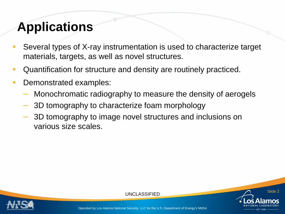
LANL’s Density Characterization
Station▪ 10-3 Torr
▪ Doubly Curved Ge Crystal
▪ 13.2 μm pixel pitch
▪ FOV = ~9 mm x ~27.5 mm
▪ Three systems
– Mo = 2.3 keV
– Cr = 5.414 keV
– Cu = 8.047 keVGain 2; 2MHz readout frequency
Low noise readout
1.36 sec exposure time
250 Accumulations
10 Accumulation dark current subtraction
Operated by Los Alamos National Security, LLC for the U.S. Department of Energy's NNSA
UNCLASSIFIEDSlide 4
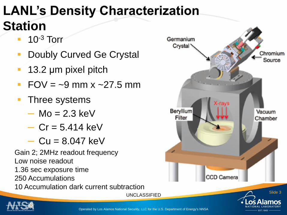
• Density (ρ) is calculated using the following equation:
ρ =−ln𝑇 ν0𝐾 ν0 𝑧
Where:
T (ν0) = transmittance at frequency ν0 , = I/ I0
ν0 = frequency of monochromatic X-ray source
K (ν0) = opacity at frequency ν0, cm2 g-1
z = depth (thickness of sample), cm
Lanier, N. E.; Hamilton, C.; Taccetti, J. M. Review of Scientific Instruments 2012, 83, 10E521.
LANL’s Density Characterization
Station

Operated by Los Alamos National Security, LLC for the U.S. Department of Energy's NNSA
UNCLASSIFIED
keV distribution
Slide 5
0 2 4 6 8 10
2
4
6
8
10
12
Y lo
ca
tio
n (
mm
)
X location (mm)
0.3900
0.3915
0.3930
0.3945
0.3960
0.3975
0.3990
0.4005
0.4020
Transmittance
The keV energy variation over the central 1 cm2, is ~0.001 transmittance.

Operated by Los Alamos National Security, LLC for the U.S. Department of Energy's NNSA
UNCLASSIFIED
Analysis of 20 mg/cm3 aerogels.
▪ Right circular cylinders were made by LANL and
LLNL, targeting 20 mg/cm3.
▪ LANL’s Cu-based Density Characterization Station
was used to image the samples, operating at 8.04
keV (Cu Kα)
▪ Samples were also measured for density,
gravimetrically.

Operated by Los Alamos National Security, LLC for the U.S. Department of Energy's NNSA
UNCLASSIFIED
Samples AA,AB▪ 10 mm-thick silica aerogel imaged with Cu-based
DCS @ 8.04 keV
▪ ROIs analyzed are indicated by yellow outline
SiO2 Aerogel AA
(ROI 1)
SiO2 Aerogel AB
(ROI 2)
Measured Density
(mode, mg cm-3) 21.6 21.1
Target Density
(mg cm-3)20 20
Measured
% Transmission
(mode)
50.3 50.8
Target
% Transmission53.0 52.7

Operated by Los Alamos National Security, LLC for the U.S. Department of Energy's NNSA
UNCLASSIFIED
Samples CA,CB▪ 10 mm-thick silica aerogel imaged with Cu-based
DCS @ 8.04 keV
▪ ROIs analyzed are indicated by yellow outline
SiO2 Aerogel CA
(ROI 1)
SiO2 Aerogel CB
(ROI 2)
Measured Density
(mode, mg cm-3) 29.5 30.1
Target Density
(mg cm-3)20 20
Measured
% Transmission
(mode)
38.8 38.2
Target
% Transmission52.7 52.8

Operated by Los Alamos National Security, LLC for the U.S. Department of Energy's NNSA
UNCLASSIFIED
Samples DA,DB▪ 10 mm-thick silica aerogel imaged with Cu-based
DCS @ 8.04 keV
▪ ROIs analyzed are indicated by yellow outline
SiO2 Aerogel DA
(ROI 1)
SiO2 Aerogel DB
(ROI 2)
Measured Density
(mode, mg cm-3) 34.1 30.8
Target Density
(mg cm-3)20 20
Measured
% Transmission
(mode)
35.4 38.0
Target
% Transmission54.3 53.3
Operated by Los Alamos National Security, LLC for the U.S. Department of Energy's NNSA
UNCLASSIFIED
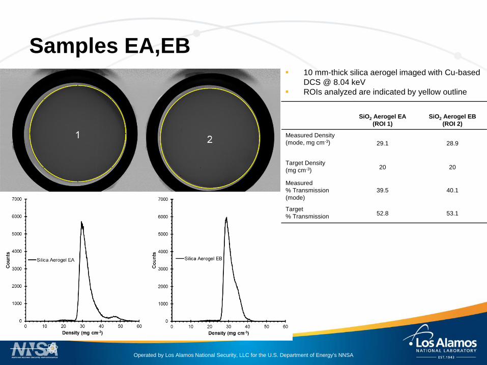
Samples EA,EB▪ 10 mm-thick silica aerogel imaged with Cu-based
DCS @ 8.04 keV
▪ ROIs analyzed are indicated by yellow outline
SiO2 Aerogel EA
(ROI 1)
SiO2 Aerogel EB
(ROI 2)
Measured Density
(mode, mg cm-3) 29.1 28.9
Target Density
(mg cm-3)20 20
Measured
% Transmission
(mode)
39.5 40.1
Target
% Transmission52.8 53.1

Operated by Los Alamos National Security, LLC for the U.S. Department of Energy's NNSA
UNCLASSIFIED
Samples FA,FB▪ 10 mm-thick silica aerogel imaged with Cu-based
DCS @ 8.04 keV
▪ ROIs analyzed are indicated by yellow outline
SiO2 Aerogel FA
(ROI 1)
SiO2 Aerogel FB
(ROI 2)
Measured Density
(mode, mg cm-3) 28.3 28.9
Target Density
(mg cm-3)20 20
Measured
% Transmission
(mode)
40.8 40.2
Target
% Transmission53.0 53.2

Operated by Los Alamos National Security, LLC for the U.S. Department of Energy's NNSA
UNCLASSIFIED
Samples LANL: 1 & 2▪ 3 mm-thick silica aerogel imaged with Cu-based
DCS @ 8.04 keV
▪ ROIs analyzed are indicated by yellow outline
SiO2 Aerogel
(ROI 1)
SiO2 Aerogel
(ROI 2)
Measured Density
(mode, mg cm-3) 24.0 21.7
Target Density
(mg cm-3)20 20
Measured
% Transmission
(mode)
75.2 74.5
Target
% Transmission78.9 75.9

Operated by Los Alamos National Security, LLC for the U.S. Department of Energy's NNSA
UNCLASSIFIED
Samples LANL: 3 & 4▪ 3 mm-thick silica aerogel imaged with Cu-based
DCS @ 8.04 keV
▪ ROIs analyzed are indicated by yellow outline
SiO2 Aerogel
(ROI 3)
SiO2 Aerogel
(ROI 4)
Measured Density
(mode, mg cm-3) 18.6 23.6
Target Density
(mg cm-3)20 20
Measured
% Transmission
(mode)
76.2 75.2
Target
% Transmission74.6 78.5

Operated by Los Alamos National Security, LLC for the U.S. Department of Energy's NNSA
UNCLASSIFIED
Samples LANL: 5 & 6▪ 3 mm-thick silica aerogel imaged with Cu-based
DCS @ 8.04 keV
▪ ROIs analyzed are indicated by yellow outline
SiO2 Aerogel
(ROI 5)
SiO2 Aerogel
(ROI 6)
Measured Density
(mode, mg cm-3) 23.0 26.6
Target Density
(mg cm-3)20 20
Measured
% Transmission
(mode)
72.4 72.7
Target
% Transmission75.5 78.7

Operated by Los Alamos National Security, LLC for the U.S. Department of Energy's NNSA
UNCLASSIFIED
Summary
Samples
Average Measured
Density
(DCS, mg cm-3)A,B
Average Measured
Density
(DCS, mg cm-3)A,C
Average Measured
Density
(Gravimetric, mg cm-3)A
LLNL 26.1 ± 3.4 28.2 ± 4.0 30.7 ± 0.56
LANL 28.9 ± 2.0 22.9 ± 1.5 22.0 ± 0.68D
A Errors are standard deviations of the average for the many samples.B Measured density using the mold size as the X-ray path lengthC Measured density using the true thickness of the sample as the X-ray path lengthD LANL aerogels were too light to measure individually, therefore 14 of them were weighed together to
produce an average mass.
Operated by Los Alamos National Security, LLC for the U.S. Department of Energy's NNSA
UNCLASSIFIED
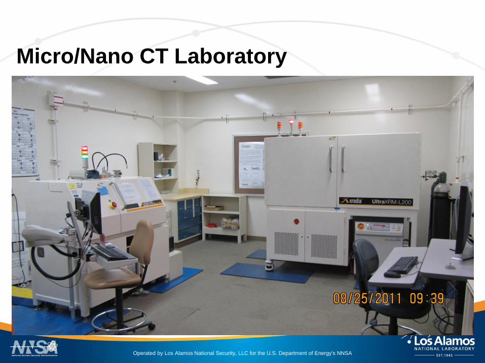
Micro/Nano CT Laboratory

Operated by Los Alamos National Security, LLC for the U.S. Department of Energy's NNSA
UNCLASSIFIED
Xradia Micro Computed TomographyX-ray Source: Micro Focus Hamamatsu 5 m spot, 40
– 150 kV acceleration voltage, 10 W total power (4W
nominal)
Detector: 2k x 2k Electrically Cooled CCD, 4
objectives
Available Objectives:
2X 6 m/ pixel, 12 mm FOV
4X 3 m/ pixel, 6 mm FOV
10 X 1.2 m/ pixel, 2.4 mm FOV
20X 0.6 m/ pixel, 1.2 mm FOV (1.5 m resolution)
In-situ studies:
Sample may be imaged in states of either
tension or compression
Dynamic changes can be tracked in 3D

Operated by Los Alamos National Security, LLC for the U.S. Department of Energy's NNSA
UNCLASSIFIED
Xradia UltraXRMLarge FOV = 65 µm, 150 nm resolution
Small FOV = 15 µm, 50 nm resolution
Absorption or Zernike phase contrast

Operated by Los Alamos National Security, LLC for the U.S. Department of Energy's NNSA
UNCLASSIFIED
X-ray micro-scale imaging of marble capsules
Three DVB foam filled capsules were received and imaged using micro tomography
Sample ID’s Include:
Omega-Marble 16A 90 µm pore CHCD#26
Omega-Marble 16A 50 µm pore CHCD #15
Omega-Marble 16A 30 µm pore CHCD #12
Glass capsules are used as the pore former and are then etched out, leaving the pore
structure behind.
Physicists need to know the void size and distribution within the capsules; to get the
experimental pre-mix conditions.
Samples were imaged using Micro CT:
20X objective, 1 mm field of view, 1.07 µm voxel size, 40 kVp,
10W

Operated by Los Alamos National Security, LLC for the U.S. Department of Energy's NNSA
UNCLASSIFIEDSlide 20
Omega-Marble 16A 30 µm pore CHCD #12
0
100
200
300
400
500
600
0 20 40 60
Occu
ren
ces
Equivalent Diameter (micrometers)
27 µm average void diameter
59.7% void volume
Operated by Los Alamos National Security, LLC for the U.S. Department of Energy's NNSA
UNCLASSIFIEDSlide 21
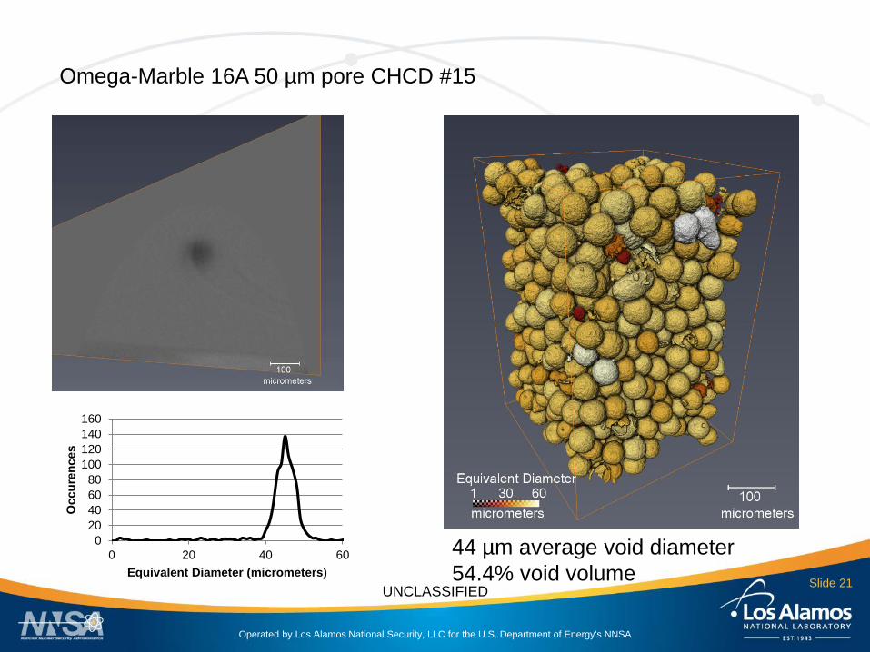
Omega-Marble 16A 50 µm pore CHCD #15
0
20
40
60
80
100
120
140
160
0 20 40 60
Occu
ren
ces
Equivalent Diameter (micrometers)
44 µm average void diameter
54.4% void volume
Operated by Los Alamos National Security, LLC for the U.S. Department of Energy's NNSA
UNCLASSIFIEDSlide 22
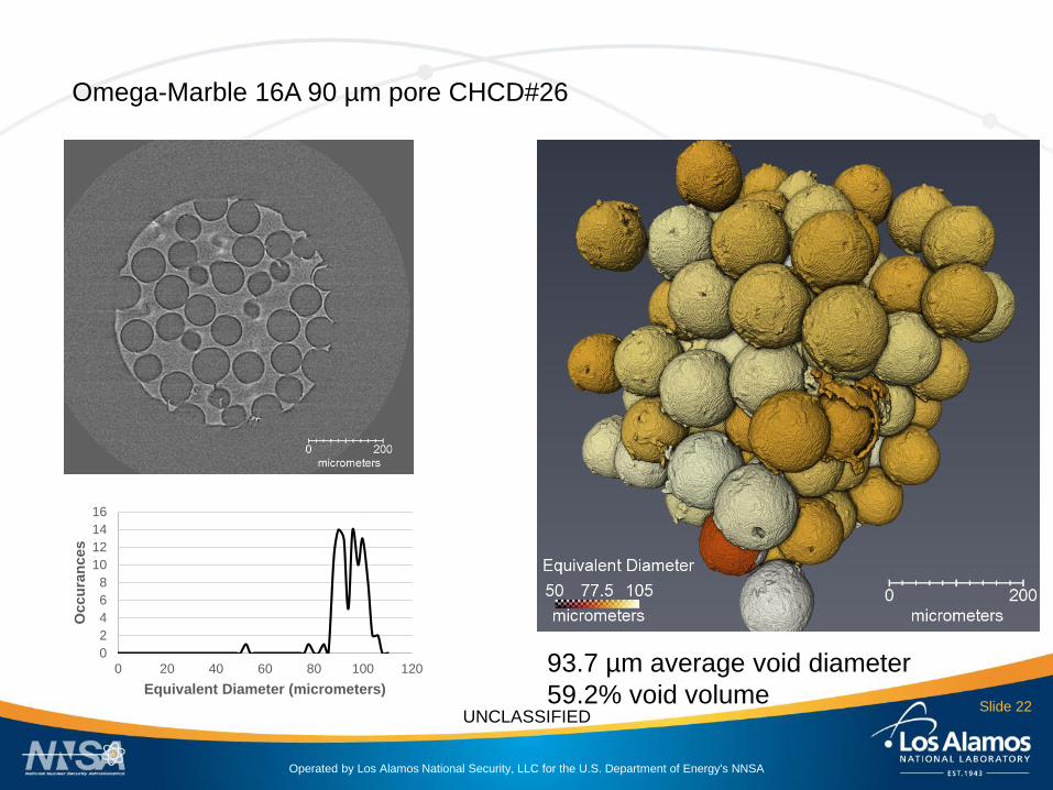
Omega-Marble 16A 90 µm pore CHCD#26
93.7 µm average void diameter
59.2% void volume
0
2
4
6
8
10
12
14
16
0 20 40 60 80 100 120
Occu
ran
ces
Equivalent Diameter (micrometers)

Operated by Los Alamos National Security, LLC for the U.S. Department of Energy's NNSA
UNCLASSIFIED
3D printed capsule with microlatticeCharacterization of 3D printed capsule, 300 micrometers in diameter, with an interior
hexagonal microlattice using Nanoscribe 2PP instrument.
Physicists want better control and flexibility over the structure within the capsule
(see previous slides). Near zero density material for suspending inner capsules with
respect to double-shell design.

Operated by Los Alamos National Security, LLC for the U.S. Department of Energy's NNSA
UNCLASSIFIEDSlide 24
Imaged using SEM (electron microscope) and Micro CT (X-ray computed tomography)
Micro CT system was operated at:
20X magnification, 40kVp, 10 W, 1.0 micrometer voxel size.
Optical photo of capsule.
Rendering of
CAD file
Measurements

Operated by Los Alamos National Security, LLC for the U.S. Department of Energy's NNSA
UNCLASSIFIED
Electron microscope images of the capsule
- Lattice ligaments are approximately 2 micrometers in diameter

Operated by Los Alamos National Security, LLC for the U.S. Department of Energy's NNSA
UNCLASSIFIED
CT rendering of capsule
Ligaments are ~1.5
micrometers
in diameter
CT voxel size is ~1 micrometers
Therefore the ligaments were
also imaged and rendered using
nano-scale CT.

Operated by Los Alamos National Security, LLC for the U.S. Department of Energy's NNSA
UNCLASSIFIED
Results:
The capsule printed with the interior hexagonal lattice.
Lattice is connected to the interior wall of the capsule.
A wedge was left out of the capsule wall to ease in the removal of the printing
fluid.
Capsule was probably ‘squished’ a bit as a result of handling. Some of the
ligaments are deformed and there is a flat area of the outer wall.
Ligaments are 1-2 micrometers in thickness; this is below the resolution of the
micro-CT. A 3D image of the capsule is currently underway using the nano-CT
instrument.

Operated by Los Alamos National Security, LLC for the U.S. Department of Energy's NNSA
UNCLASSIFIED
Rochester sent us a cryogenic capsule to image some features that they were
seeing optically.
The capsule was received and mounted on a flattened tip of a finishing nail
using UV curable glue.
The capsule was imaged initially with an Xradia (Carl Zeiss X-ray Microscopy
Inc.) micro CT using the 20X objective. Nominal voxel size of 1 micrometer.
This was used to image the entire capsule.
Several images were collected of the capsule using our Xradia Ultra XRM.
High resolution, phase contrast modality; 15 micrometer FOV, 15 nanometer
voxel size.
The spot of interest is less than 0.5 micrometers in size and could not be
located in normal absorption contrast. It is within the wall of the sample. (It
may be a trapped air bubble??) Two surface contaminants were also identified
and imaged separately.
Nano-scale CT of a cryogenic capsule
Operated by Los Alamos National Security, LLC for the U.S. Department of Energy's NNSA
UNCLASSIFIED
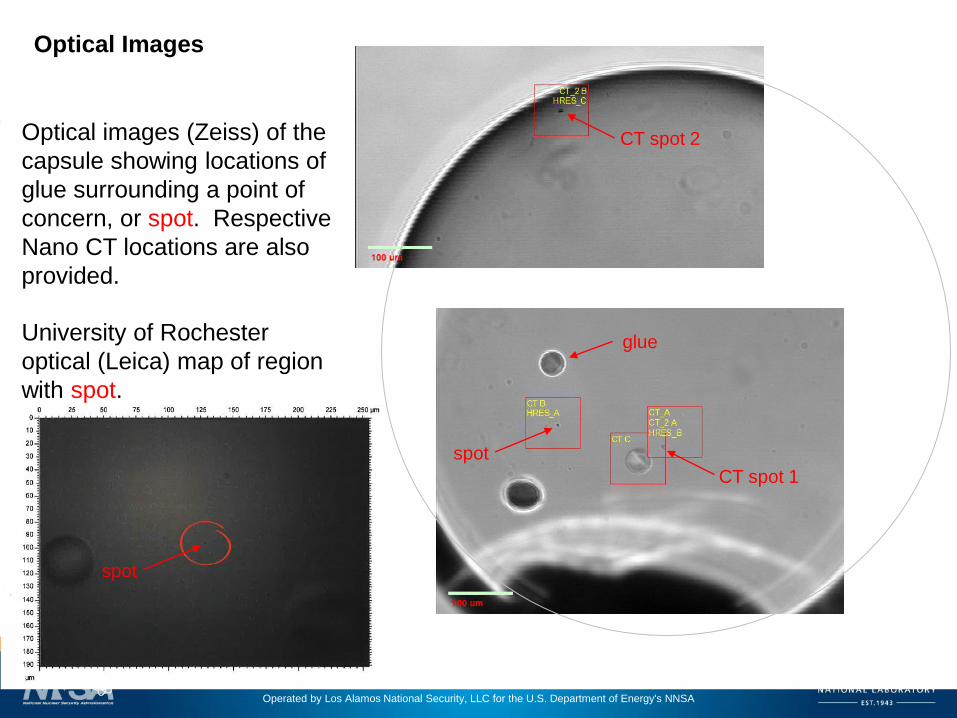
Optical images (Zeiss) of the
capsule showing locations of
glue surrounding a point of
concern, or spot. Respective
Nano CT locations are also
provided.
spot
CT spot 1
glueUniversity of Rochester
optical (Leica) map of region
with spot.
spot
CT spot 2
Optical Images

Operated by Los Alamos National Security, LLC for the U.S. Department of Energy's NNSA
UNCLASSIFIED
Micro CT reconstructions of the complete
capsule. At this resolution, no features of
the spot can be recognized. CT spots 1
and 2 can be easily detected.
CT spot 2
CT spot 1
CT spot 1
Operated by Los Alamos National Security, LLC for the U.S. Department of Energy's NNSA
UNCLASSIFIED
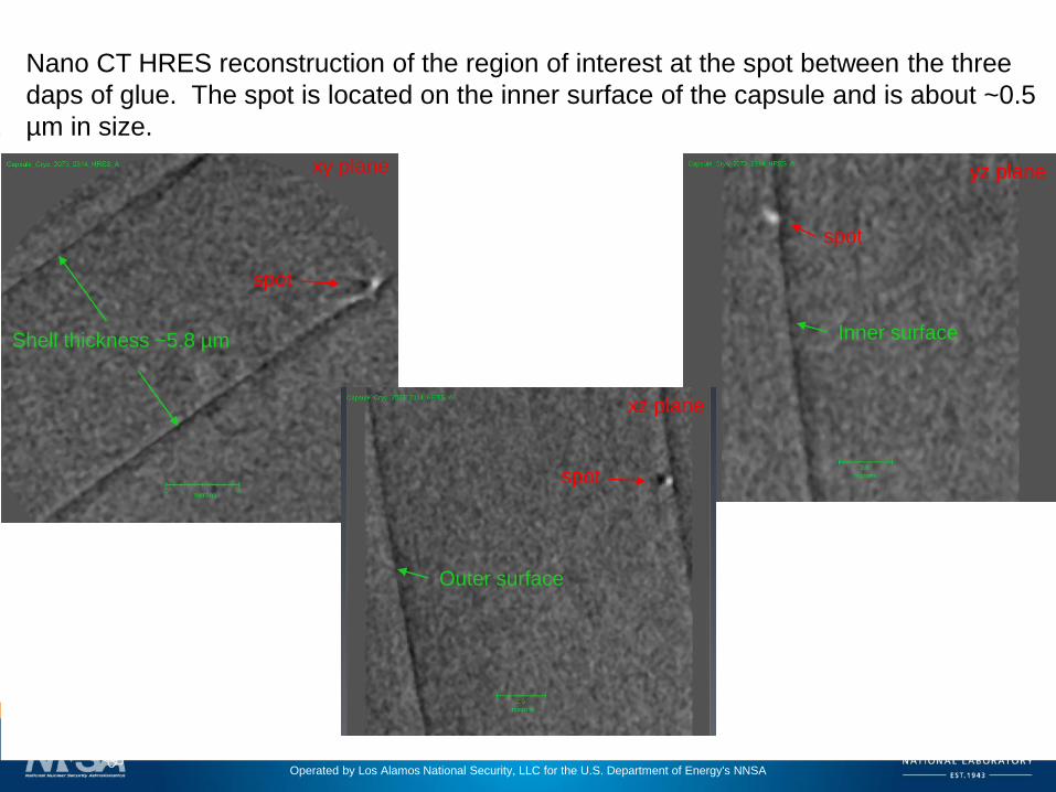
Nano CT HRES reconstruction of the region of interest at the spot between the three
daps of glue. The spot is located on the inner surface of the capsule and is about ~0.5
µm in size.
xy plane
xz plane
yz plane
Shell thickness ~5.8 µm
spot
Inner surface
Outer surface
spot
spot
Operated by Los Alamos National Security, LLC for the U.S. Department of Energy's NNSA
UNCLASSIFIED
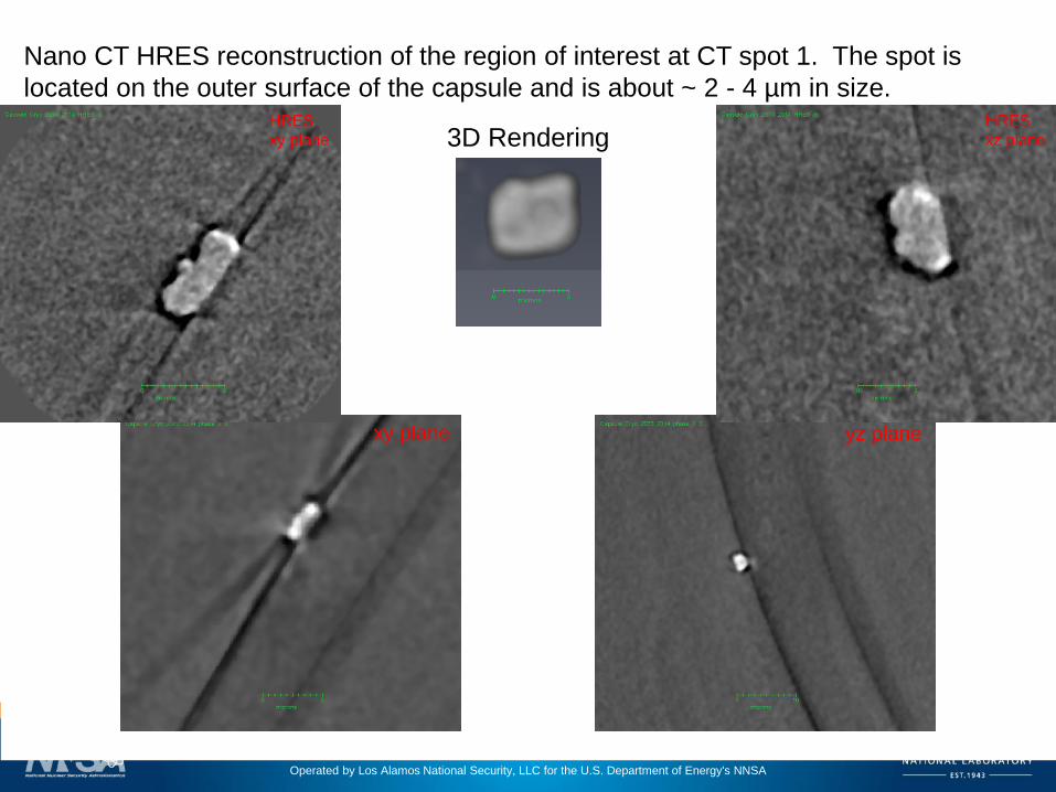
Nano CT HRES reconstruction of the region of interest at CT spot 1. The spot is
located on the outer surface of the capsule and is about ~ 2 - 4 µm in size.
3D Rendering
xy plane
HRES
xy plane
HRES
xz plane
yz plane

Operated by Los Alamos National Security, LLC for the U.S. Department of Energy's NNSA
UNCLASSIFIED
Nano CT HRES reconstruction of the region of interest at CT spot 2. The spot is
located on the outer surface of the capsule and is also about ~ 3 - 5 µm in size. HRES
xy plane
HRES
xz plane
xy plane xz plane

Operated by Los Alamos National Security, LLC for the U.S. Department of Energy's NNSA
UNCLASSIFIED
Conclusions:
LANL uses a variety of X-ray instruments (confocal XRF will be shown in the
poster) to characterize target materials, targets (see Tana’s talk), novel
designs, and defects.
Monochromatic radiography is used to measure the density of low density
materials as well as thin films (not shown today). This technique also provides
2D radiographs that can filter out samples that may meet the density
specification, but have other issues.
Micro CT is used to measure void size, shape and distribution, providing the
physicists a true understanding of the as-shot material.
Nano CT is used to image smaller features and defects.