Embed Size (px)
Citation preview
https://erjm.journals.ekb.eg ERJ Engineering Research Journal
Faculty of Engineering
Menoufia University
ISSN: 1110-1180
DOI: 10.21608/ERJM.2020.95135
ERJ, PART 1: Electric Eng., Vol. 43, No. 3, July 2020, pp. 185-193 185
Characteristics of a Sinusoidally-Distributed Cylindrical-Rotor
Self-Excited Single-Phase Synchronous Generator
Helmy Awad1, Elwy E. Elkholy
2
1Faculty of Technology and Industrial Education, Helwan University, Cairo, Egypt
2Electric Eng. Dept., Faculty of Engineering, Menoufia University, Egypt.
ABSTRACT
The small-scale power systems favor the installation of self-excited synchronous generators due to their simple
construction. Many configurations were reported in the literature but there have been always two issues:
voltage regulation (VR) and total harmonic distortion (THD) of the output voltage. This paper presents an
experimental investigation to improve the performance of single-phase, self-excited, synchronous generator
(SPSESG) in terms of the VR and THD. The applied modification is the implementation of sinusoidally-
distributed stator windings which implies a different number of turns in each slot. A typical lab single-phase
synchronous machine was rewound with the proper number of turns in each slot and then tested against
resistive, resistive-inductive, resistive-capacitive, and dynamic loads (induction motor).
The experimental results proved that the modified generator performance has significantly improved in terms
of the VR and THD. The worst VR was recorded in the case of dynamic load and it was 6.5 %. While the
highest THD was 4.5 %, at no load. These figures are much better than other configurations reported in the
literature.
Keywords: Self-excited; Sinusoidally-distributed windings; Synchronous generator; Voltage regulation.
1. INTRODUCTION
For standalone (isolated) energy systems, self-
excited generators offer a viable solution [1,2,3]
because of their simple construction and high
reliability. Three-phase self-excited induction
generators are implemented in standalone
applications, particularly in wind power systems
[4,5,6]. Most commonly, three-phase self-excited
synchronous generators are exploited in many
applications [7,8,9]. However, in the case of small-
scale power systems such as micro-hydro, a single-
phase self-excised synchronous generator
(SPSESG) is more suited [10,11,12,13].
Few configurations of SPSESG have been reported
and well-explained in literature such as Series
Connected Synchronous Generator [14,15,16],
Cylindrical Rotor Synchronous Generator,
Reluctance Synchronous Generator [9, 17],
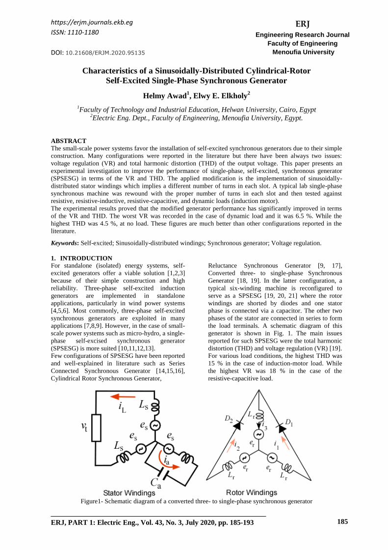
Converted three- to single-phase Synchronous
Generator [18, 19]. In the latter configuration, a
typical six-winding machine is reconfigured to
serve as a SPSESG [19, 20, 21] where the rotor
windings are shorted by diodes and one stator
phase is connected via a capacitor. The other two
phases of the stator are connected in series to form
the load terminals. A schematic diagram of this
generator is shown in Fig. 1. The main issues
reported for such SPSESG were the total harmonic
distortion (THD) and voltage regulation (VR) [19].
For various load conditions, the highest THD was
15 % in the case of induction-motor load. While
the highest VR was 18 % in the case of the
resistive-capacitive load.
Figure1- Schematic diagram of a converted three- to single-phase synchronous generator

Helmy Awad, Elwy E. Elkholy " Characteristics of a Sinusoidally-Distributed Cylindrical-Rot…"
ERJ, Menoufia University, Vol. 43, No. 3, July 2020 186
This paper presents the experimental results of a
modified SPSESG where the above-mentioned
issues are minimized. Section II of the paper
presents the proposed modifications while Section
III displays the experimental results at no loads
and various loading conditions. Section IV
presents a comparison between the modified
generator and the converted three- to single-phase
generator.
2. PROPOSED MODIFICATION
In this work, the typical field winding of a
synchronous generator was used but shorted via a
diode so that the field current is unidirectional and
the rotor magnetization axis in space is fixed.
The stator windings involve both main and
auxiliary coils where the auxiliary windings are
connected to a variable capacitor. Adjusting the
value of the capacitance represents a key to the
operation of the generator and can be used for
voltage regulation. Fig. 2 shows a schematic
diagram of the modified SPSESG. The basic idea
of the self-excitation can be summarized as
follows. The rotor field winding is rotated by a
prime mover with a constant speed, which induces
a small amount of voltage on the stator main
windings due to the residual magnetism. Also, the
field current is induced in the rotor windings
which is then rectified by the diode. Increasing the
value of the capacitance in the auxiliary windings
increases the current induced in field windings and
so on until a critical value of the capacitor is
reached after which the induced voltage builds up
and then the generator is successfully started.
The main proposed modification is to exploit
sinusoidally-distributed windings in the main and
auxiliary coils. The magnetic axes of these
windings must have a 90° displacement space,
despite that they are composed of coils distributed
in space around the air gap periphery.
If the produced flux is sinusoidally distributed in
space, then the induced voltage would be
sinusoidal in time [22]. To reduce the THD of the
induced voltage waveform, sinusoidally-
distributed windings arrangements are proposed
for both main and auxiliary windings.
Figure 2- Construction of AC machine under
investigation
The main and auxiliary windings are wound using
the distributed concentric single-phase winding
method as it offers high-quality flux distribution
and higher efficiency [23]. In such a winding, the
outer coils of each pole have a longer span and a
higher pitch factor while the inner coils have the
advantage of a shorter end connection. For a 24-
slot 2-pole stator, the layout of the winding is
illustrated in Fig. 3, where M1 and M2 are the
terminals of the main windings while A1 and A2
are the terminals of the auxiliary windings.
To achieve a sinusoidal distribution of the field
flux, the number of conductors in each slot is
varied according to the sine half the angle of the
coil span like that given in Table 1.
Table 1- Sinusoidal distribution of stator windings
Main Windings Auxiliary
Winding
Coil
Span
Angle
[Deg]
sin
(Angle/2)
% of Turns =
100*sin
(Angle/2)/sum
Coil
Span
% of
Turns
1-13 90 0.70711 27.34 7-19 27.34
2-12 75 0.60876 23.54 8-18 23.54
3-11 60 0.5 19.33 9-17 19.33
4-10 45 0.38268 14.79 10-16 14.79
5-9 30 0.25882 10.00 11-15 10.00
6-8 15 0.13053 5.00 12-14 5.00
sum 2.5879

Helmy Awad, Elwy E. Elkholy " Characteristics of a Sinusoidally-Distributed Cylindrical-Rot…"
ERJ, Menoufia University, Vol. 43, No. 3, July 2020 187
(a)
(b)
Figure 3- Windings layout of presented design: of SPSESG: (a) main winding and
(b) auxiliary winding
Helmy Awad, Elwy E. Elkholy " Characteristics of a Sinusoidally-Distributed Cylindrical-Rot…"
ERJ, Menoufia University, Vol. 43, No. 3, July 2020 188
3. EXPERIMENTAL RESULTS
A. No-Load Characteristics
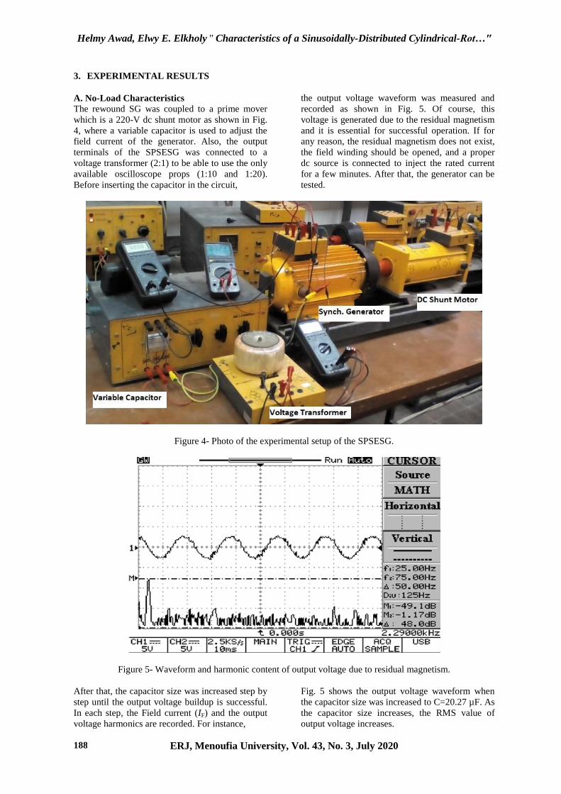
The rewound SG was coupled to a prime mover
which is a 220-V dc shunt motor as shown in Fig.
4, where a variable capacitor is used to adjust the
field current of the generator. Also, the output
terminals of the SPSESG was connected to a
voltage transformer (2:1) to be able to use the only
available oscilloscope props (1:10 and 1:20).
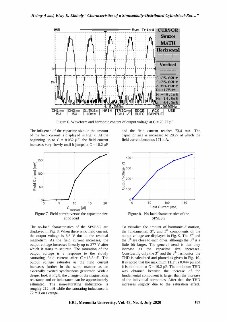
Before inserting the capacitor in the circuit,
the output voltage waveform was measured and
recorded as shown in Fig. 5. Of course, this
voltage is generated due to the residual magnetism
and it is essential for successful operation. If for
any reason, the residual magnetism does not exist,
the field winding should be opened, and a proper
dc source is connected to inject the rated current
for a few minutes. After that, the generator can be
tested.
Figure 4- Photo of the experimental setup of the SPSESG.
Figure 5- Waveform and harmonic content of output voltage due to residual magnetism.
After that, the capacitor size was increased step by
step until the output voltage buildup is successful.
In each step, the Field current (IF) and the output
voltage harmonics are recorded. For instance,
Fig. 5 shows the output voltage waveform when
the capacitor size was increased to C=20.27 µF. As
the capacitor size increases, the RMS value of
output voltage increases.
Helmy Awad, Elwy E. Elkholy " Characteristics of a Sinusoidally-Distributed Cylindrical-Rot…"
ERJ, Menoufia University, Vol. 43, No. 3, July 2020 189
Figure 6. Waveform and harmonic content of output voltage at C = 20.27 µF
The influence of the capacitor size on the amount
of the field current is displayed in Fig. 7. At the
beginning up to C = 8.052 F, the field current
increases very slowly until it jumps at C = 10.2 F
and the field current reaches 73.4 mA. The
capacitor size is increased to 20.27 at which the
field current becomes 171 mA.
Figure 7- Field current versus the capacitor size
at no load
Figure 8 - No-load characteristics of the
SPSESG
The no-load characteristics of the SPSESG are
displayed in Fig. 8. When there is no field current,
the output voltage is 6.8 V due to the residual
magnetism. As the field current increases, the
output voltage increases linearly up to 377 V after
which it starts to saturate. The saturation of the
output voltage is a response to the slowly
saturating field current after C = 13.3 µF. The
output voltage saturates as the field current
increases further in the same manner as an
externally excited synchronous generator. With a
deeper look at Fig.8, the change of the magnetizing
reactance and or inductance can be approximately
estimated. The non-saturating inductance is
roughly 212 mH while the saturating inductance is
72 mH on average.
To visualize the amount of harmonic distortion,
the fundamental, 3rd
, and 5th
components of the
output voltage are displayed in Fig. 9. The 3rd
and
the 5th
are close to each other, although the 3rd
is a
little bit larger. The general trend is that they
increase as the capacitor size increases.
Considering only the 3rd
and the 5th
harmonics, the
THD is calculated and plotted as given in Fig. 10.
It is noted that the maximum THD is 0.044 pu and
it is minimum at C = 10.2 µF. The minimum THD
was obtained because the increase of the
fundamental component is larger than the increase
of the individual harmonics. After that, the THD
increases slightly due to the saturation effect.

Helmy Awad, Elwy E. Elkholy " Characteristics of a Sinusoidally-Distributed Cylindrical-Rot…"
ERJ, Menoufia University, Vol. 43, No. 3, July 2020 190
Figure 9- 1
st, 3
rd and 5
th harmonics of the out
voltage versus the capacitor size at no load
Figure 10- Total Harmonic Distortion of the
output voltage in case of no load
B. Loading Characteristics
B.1. Static Loads
The generator was tested with resistive, resistive-
inductive, and resistive-capacitive loads. The tests
were limited to those loads available in the lab. In
each load step, the output voltage (Vt), the
armature current (Ia), and the harmonic
components: 1st, 3
rd, and 5
th of the output voltage
are recorded. Fig. 11 depicts the load
characteristics of the three load types. The voltage
regulation (VR) is the least (5.67 %) in the case of
the resistive-inductive load. However, it will be
even lower if the load is increased. But on the
other hand, the generator is working steadily under
the three load types.
The 3rd
and 5th
harmonics of the load voltage are
displayed versus the load current for the three load
types in Fig 12. The 3rd
harmonic generally
decreases as the load increases and its maximum is
3.3 %. Regarding the 5th
harmonic, in the case of
resistive-inductive load, it increases as the load
increases but on the other two cases, it decreases.
The maximum of the 5th
harmonic was 2.5 % in
the case of the resistive-inductive load. Based on
the 3rd
and 5th
harmonics, the THD was calculated
and is displayed in Fig. 13. The general trend
noticed from Fig.13 is that the THD decreases as
the load increases.
Figure 11- Load characteristics of SPSESG
in case of static loads
(a)
(b)
Figure 12- Percentage of Harmonics of load voltage of SPSESG in case of static loads: (a) 3rd
and (b) 5th
0 5 10 15 200
0.01
0.02
0.03
0.04
Total Harmonic Distortion
Cins
[uF]
TH
Dv
[pu]

Helmy Awad, Elwy E. Elkholy " Characteristics of a Sinusoidally-Distributed Cylindrical-Rot…"
ERJ, Menoufia University, Vol. 43, No. 3, July 2020 191
Figure 13- Percentage of THD of load voltage
of SPSESG in case of static loads
B.2. Dynamic Load: Single-Phase Induction
Motor
A single-phase induction motor is connected
across one of the stator phases and a mechanical
brake is applied to the motor to vary its load. Fig.
14 presents the load characteristics of the SPSESG
in this case. The minimum drawn current was 1.6
A which yields an output voltage of 157 V. When
the armature current increases to 2.3 A, the
generator output voltage decreases to 148 V and
the corresponding VR is 6.5 %.
Figure 14- Load characteristics of SPSESG
in case of induction-motor load
Fig. 15 shows the 3rd
, 5th
harmonics, and the THD
of the output voltage in the case of induction-
motor load. It is noted that the 5th
harmonic is
constant at 5.25 % while the 3rd
harmonic drops
from 8.3 to 7.6 %. The THD decreased from 8.45
at no load to 7.84 at full load. The presence of
harmonics is evident also in the voltage waveform
as shown in Fig. 16.
Fig. 15. % Harmonics of load voltage of SPSESG
in case of induction-motor l
Fig. 16. Waveform of the output voltage of
SPSESG in case of induction-motor load
4. DISCUSSIONS
Here, the performance of the modified SPSESG is
compared to the configuration presented in [19].
The comparison is concluded in Table 3, where it
is clear that the VR has improved. For instance,
taking the case of induction motor in both
configurations, the VR has decreased from 14 to
6.5%. This is a considerable achievement.
Regarding the THD of the output voltage, it
decreased from 13.5 % to 4.45 %, which is also a
considerable achievement. However, it needs more
work to completely understand and analyze the
performance of this type of generator. Detailed
models are required considering the high
nonlinearity caused by the presence of the diode in
the rotor field circuits. Automatic voltage
regulators for this generator may be a good area of
research in this context.

Helmy Awad, Elwy E. Elkholy " Characteristics of a Sinusoidally-Distributed Cylindrical-Rot…"
ERJ, Menoufia University, Vol. 43, No. 3, July 2020 192
Table 3- Comparison between the converted three-phase to single-phase
configuration and the proposed modified SPSESG
Type load Converted 3-ph to1-ph Modified SPSESG
THD pu VR % THD pu VR %
No-load 0.135 -- 0.0441 --
Resistive 0.0459 16 0.0382 4.8
Resistive-capacitive 0.0471 18 0.0382 1.96
Resistive-inductive 0.0516 12 0.0346 5.67
Dynamic loads 0.15 14 0.10 8.1
5. CONCLUSIONS
The design of the self-excited synchronous
generator has been modified and tested against
static and dynamic loads. Static loads include
resistive, resistive-capacitive, and resistive-
inductive. Dynamic loads are represented by a
single-phase induction motor with mechanical
braking. It was found that the generator
performance was satisfactorily robust in terms of
the output voltage regulation. The maximum
voltage regulation was 6.5 %, which was less than
other configurations reported in the literature. The
total harmonic distortion was also reduced to 6.5
% maximal compared to 13.5 % other
configurations. Detailed modeling of such
generators is highly recommended to fully
understand and control its performance.
6. REFERENCES
[1] W. E. Vanço, F. B. Silva, C. M. R. De Oliveira,
J. R. B. A. Monteiro, and J. M. M. De
Oliveira, "A Proposal of Expansion and
Implementation in Isolated Generation
Systems Using Self-Excited Induction
Generator With Synchronous Generator," in
IEEE Access, vol. 7, pp. 117188-117195,
2019.
[2] Y. Wang and N. Bianchi, "Investigation of
Self-Excited Synchronous Reluctance
Generators," in IEEE Transactions on
Industry Applications, vol. 54, no. 2, pp. 1360-
1369, March-April 2018.
[3] W. E. Vanço, F. B. Silva, F. A. S. Gonçalves,
E. O. Silva, C. A. Bissochi, and L. M. Neto,
"Experimental analysis of self-excited
induction generators operating in parallel with
synchronous generators applied to isolated
load generation," in IEEE Latin America
Transactions, vol. 14, no. 4, pp. 1730-1736,
April 2016.
[4] N. Bouchiba, S. Salem, and M. B. A.
Kammoun, "Three-phase self-excited
induction generator analysis in stand-alone
mode," IREC2015 The 6th
International
Re- newable Energy Congress, Sousse, 2015,
pp. 1-6.
[5] R. C. Bansal, "Three-phase self-excited
induction generators: an overview," in IEEE
Transactions on Energy Conversion, vol. 20,
no. 2, pp. 292-299, June 2005.
[6] K. A. Chinmaya and G. K. Singh,
"Performance evaluation of multiphase
induction generator in stand-alone and grid-
connected wind energy conversion system," in
IET Renewable Power Generation, vol. 12,
no. 7, pp. 823-831, 21 5 2018.
[7] Y. Wang and N. Bianchi, "Investigation of
Self-Excited Synchronous Reluctance
Generators," in IEEE Transactions on Industry
Applications, vol. 54, no. 2, pp. 1360-1369,
March-April 2018.
[8] C. Chakraborty and Y. T. Rao, "Performance
of Brushless Induction Excited Synchronous
Generator," in the IEEE Journal of Emerging
and Selected Topics in Power Electronics, vol.
7, no. 4, pp. 2571-2582, Dec. 2019.
[9] S. S. Maroufian and P. Pillay, "Self-Excitation
Criteria of the Synchronous Reluctance
Generator in Stand-Alone Mode of
Operation," in IEEE Transactions on Industry
Applications, vol. 54, no. 2, pp. 1245-1253,
March-April 2018.
[10] S. Nonaka and K. Kesamaru, "Analysis of
new brushless self-excited single-phase
synchronous generator by finite element
method," Conference Record of the 1992
IEEE Industry Applications Society Annual
Meeting, Houston, TX, USA, 1992, pp. 198-
203 vol.1.
[11] F. Shibata and T. Kohrin, "A Brushless, Self-
Excited Single-Phase Synchronous Generator
Operating with Load and Exciting Currents
Flowing in Armature," in IEEE Transactions
on Energy Conversion, vol. EC-2, no. 2, pp.
254-261, June 1987.
Helmy Awad, Elwy E. Elkholy " Characteristics of a Sinusoidally-Distributed Cylindrical-Rot…"
ERJ, Menoufia University, Vol. 43, No. 3, July 2020 193
[12] W. S. Abu-Elhaija and A. Muetze, "Self-
Excitation and Stability at Speed Transients of
Self-Excited Single-Phase Reluctance
Generators," in IEEE Transactions on
Sustainable Energy, vol. 4, no. 1, pp. 136-144,
Jan. 2013.
[13] F. Shibata and N. Naoe, "Characteristics of
brushless and exciter-less, self-excited
synchronous generators," Conference Record
of the 1990 IEEE Industry Applications
Society Annual Meeting, Seattle, WA, USA,
1990, pp. 293-300 vol.1.
[14] M. F. Moussa, Y. G. Dessouky and B. W.
Williams, "Control strategy of a 6 MVA
Series Connected Synchronous Generator for
wind power," IET Conference on Renewable
Power Generation (RPG 2011), Edinburgh,
2011, pp. 1-6.
[15] Tze-Fun Chan, Weimin Wang, and L. L. Lai,
"Series-connected self-excited synchronous
generator for distributed generation," IEEE
PES General Meeting, Providence, RI, 2010,
pp. 1-6.
[16] A. L. Mohamadein, H. A. Yousef, and Y. G.
Dessouky, "Series-connected self-excited
synchronous generator: steady-state and
transient behaviors," in IEEE Transactions on
Energy Conversion, vol. 14, no. 4, pp. 1108-
1114, Dec. 1999.
[17] F. Rebahi, A. Bentounsi, H. Khelifa, O.
Boulkhrachef, and D. Meherhera,
"Comparative study of a self-excited induction
and synchronous reluctance generators
capabilities," 2019 International Conference
on Advanced Electrical Engineering (ICAEE),
Algiers, Algeria, 2019, pp. 1-5.
[18] M. Abdelrazek, H. Awad, and E. E. El-Kholy,
"An experimental investigation of a self-
excited synchronous generator: Loading
characteristics and output voltage harmonics,"
2017 Nineteenth International Middle East
Power Systems Conference (MEPCON),
Cairo, 2017, pp. 823-829.
[19] Hilmy Awad, Mohamed Wadi, Essam Hamdi,
“A self-excited synchronous generator for
small hydro applications”, in Proceedings of
the International. Conference on Energy,
Environment, Ecosystems, and Sustainable
Development, 2005, pp. 1-5
[20] S. Nonaka and T. Kawaguchi, "A new
variable-speed AC generator system using a
brushless self-excited-type synchronous
machine," IEEE Transactions on Industry
Applications, Vol. 28, No. 2, pp.490-496,
March-April 1992.
[21] S. Nonaka and T. Kawaguchi, "Excitation
scheme of brushless self-excited type three-
phase synchronous machine," in Proc. of IEEE
Industry Applications Society Annual
Meeting, Vol. 1, pp. 443-448, 28 Sept.-4 Oct.
1991.
[22] BUKSNAITIS, J., 2018. Sinusoidal Three-
Phase Windings Of Electric Machines,
Springer International Publishing Switzerland,
ISBN 978-3-319-42929-8.
[23] M. A. Kabir, M. Z. M. Jaffar, Z. Wan and I.
Husain, "Design and experimental evaluation
of a multilayer AC winding configuration for
sinusoidal MMF with shorter end-turn length,"
2017 IEEE Energy Conversion Congress and
Exposition (ECCE), Cincinnati, OH, 2017, pp.
5834-5839.