Embed Size (px)
Citation preview

CHINESE JOURNAL OF MECHANICAL ENGINEERING Vol. 27, No. 1, 2014
·50·
DOI: 10.3901/CJME.2014.01.050, available online at www.springerlink.com; www.cjmenet.com; www.cjmenet.com.cn
Characteristic Verification and Parameter Optimization of Airbags Cushion System for Airborne Vehicle
WANG Hongyan1, *, HONG Huangjie1, HAO Guixiang1, DENG Huaxia2, *, RUI Qiang1, and LI Jianyang1
1 Department of Mechanical Engineering, Academy of Armored Force Engineering, Beijing 100072, China 2 School of Instrument Science and Opto-electronics Engineering, Hefei University of Technology, Hefei 230009, China
Received February 29, 2013; revised August 2, 2013; accepted November 12, 2013
Abstract: The major methods to investigate the airbags cushion system are experimental method, thermodynamic method and finite element method (FEM). Airbags cushion systems are very complicated and very difficult to be investigated thoroughly by such methods. For experimental method, it is nearly impossible to completely analyze and optimize the cushion characteristics of airbags of airborne vehicle because of charge issue, safety concern and time constraint. Thermodynamic method fails to take the non-linear effects of large airbag deformation and varied contact conditions into consideration. For finite element method, the FE model is usually complicated and the calculation takes tens of hours of CPU time. As a result, the optimization of the design based on a nonlinear model is very difficult by traditional iterative approach method. In this paper, a model based on FEM and control volume method is proposed to simulate landing cushion process of airborne vehicle with airbags cushion system in order to analyze and optimize the parameters in airbags cushion system. At first, the performance of airbags cushion system model is verified experimentally. In airdrop test, accelerometers are fixed in 4 test points distributed over engine mount, top, bottom and side armor plate of hull to obtain acceleration curves with time. The simulation results are obtained under the same conditions of the airdrop test and the simulation results agree very well with the experimental results, which indicate the established model is valid for further optimization. To optimize the parameters of airbags, equivalent response model based on Latin Hypercube DOE and radial basis function is employed instead of the complex finite element model. Then the optimal results based on equivalent response model are obtained using simulated annealing algorithm. After optimization, the maximal acceleration of airborne vehicle landing reduces 19.83%, while the energy absorption by airbags increases 7.85%. The performance of the airbags cushion system thus is largely improved through optimization, which indicates the proposed method has the capability of solving the parameter optimization problem of airbags cushion system for airborne vehicle. Keywords: airborne vehicle, airbag, nonlinear finite element method, verification, equivalent response model
1 Introduction∗
The airbags cushion system is one of the most important
technologies for the landing impact attenuation of airborne vehicle. There are many landing technologies, such as honeycomb[1] and retro[2], which normally have complicated structures and thus are very expensive. Airbags cushion system is comparatively simple, convenient, efficient and cheap[3]. The airbags cushion system of the airborne vehicle has the ability to absorb the majority of impact energy, reduce the impact force for vehicle landing and subsequently protect the instruments carried by the airborne vehicles.
Airbags cushion systems absorb the impact kinetic energy by exhausting the inflation gas through vents in a controllable way. The parameter optimization is very important for the design of airbags cushion system. The research on airbags is traced to the late 1950s. Several
* Corresponding authors. E-mail: [email protected], [email protected] © Chinese Mechanical Engineering Society and Springer-Verlag Berlin Heidelberg 2014
researchers from Lewis Research Center conducted an analytical study to develop a procedure for determining the deceleration characteristics of vehicles landing on gas-filled bags of various arbitrary shapes[4]. In 1963, BROWNING proposed a simple theory of the compression of a cylindricnl airbag shock absorber and studied the compression process by means of over 1 000 step-by-step integrations[5]. The effects of bag loading, height, orifice area and the speed of the descent on the airbag cushion capability can be roughly evaluated by this method. In 1999, GARDINIER and TAYLOR from Irvin Aerospace Inc studied the airbag portion of the K-l Reusable Launch Vehicle landing system[6]. They used explicit Finite Element Analysis technique to analyze airbag fabric stresses, attachment loads, and structural interface loads. The simulation results in their paper agree with the dynamic test data to a certain extent. The investigation on airbags in Mainland China started in the late 1990s. Landing characteristics of two kinds of aerocraft utilizing airbags as shock absorbers were investigated experimentally by WAN, et al from Harbin Institute of

CHINESE JOURNAL OF MECHANICAL ENGINEERING
·51·
Technology in 2003[7]. WANG, et al[8], established a simulation model of airbag cushion process for cargo airdrop system based on thermodynamics method. They claimed that the model has the ability to calculate some cushion characteristics such as the maximal over-loading and period of the cushion process.
Among the numerous researches on airbags cushion system, the prevailing methods are experimental method, thermodynamic method and finite element method (FEM). The analysis result of experimental method is reliable and usually used for the validation of the results obtained by other methods. However, it is practically impossible to analyze and optimize the cushion characteristics of airbags of airborne vehicle only by experimental methods. The major reason is that the on-site experiments of airborne vehicle landing can be very expensive. The safety concern and time constraints are the other two unnegligible reasons. Airbags can be evaluated by thermodynamics method or FEM. But the non-linear effects of large airbag deformation and varied contact conditions means that transient explicit finite element analysis is the viable means of accurately modeling impact behavior. Several complex airbag models have been established on the basis of FEM. But these simulations require tens of hours of CPU time for impact of a few tenths of a second duration. It’s impractical to optimize a design directly using original non-linear FEMs. The establishment of equivalent response model is an effectual way to shorten the time of optimization.
In this paper, a dynamic model for airborne vehicle with airbags cushion system is established based on control volume model and FEM. The established model is validated by experiments. The simulation results agree very well with experimental results. Furthermore, the parameters of the airbags are optimized by using equivalent response model.
2 Establishment of FE Model
2.1 Control volume model of airbag
Airbags can be regarded as a kind of expanding control volume [9] as shown in Fig. 1. The control volume model of airbags can be modeled on the basis of the following assumptions [10].
Fig. 1. Control volume model
(1) The aerodynamic resistance is infinitesimal and negligible in landing process of airborne vehicle.
(2) The permeability of the shell of airbags is ignored as the air in the airbag is assumed to be expulsed only through vents in landing process.
(3) The pressure in airbags is assumed to be evenly distributed.
(4) Perfect gas law and adiabatic condition are assumed to be valid for gas in airbags during landing cushion process, because of the short impact duration and hereby limited heat exchange to the surrounding atmosphere.
In FEM calculation, control volume is given as
1
d d d d ,N
x i ix ii
V x y z xn x n A
Γ (1)
where ix is mean value of x coordinate value of element i, nix is direction cosine between normal of element and x direction, Ai is the surface area of element i.
The mass flow rate in control volume is given by the mass flow of gas injected into airbag and the mass flow of gas expulsed out of airbag:
in out ,m m m (2)
where inm is the mass flow of gas injected into airbag,
outm is the mass flow of gas expulsed out of airbag. The gas injection process has been ended before landing
cushion process for airbags. Thus the mass flow of gas injected into airbag during landing process is negligible in the simulation. The mass flow of gas expulsed out of airbag is given as
1 1
ext extout
2 1 ,1
p ppm kAp pRT
γγ γγ
γ
(3)
where k is discharge coefficient, A is the area of vent hole, pext is ambient pressure.
2.2 FE model of airbags
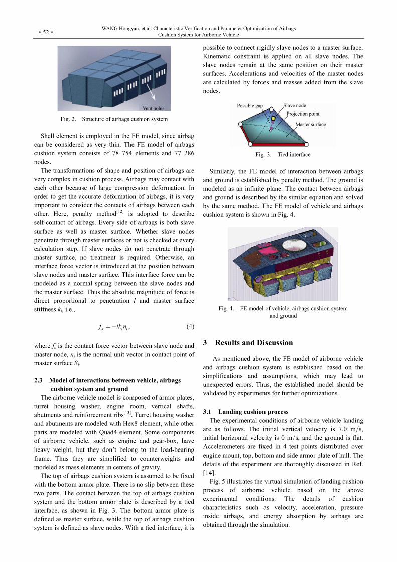
Airbags cushion system consists of eight independent and identical airbags. They are connected to the bottom of airborne vehicle. As shown in Fig. 2, each airbag has a main chamber and an assistant chamber. The assistant chamber is connected with main chamber through communication holes. Injection holes are located in the bottom of the main chamber in order to implement air inflation when airborne vehicle descends. When the bottoms of airbags contact ground, injection holes are closed. Vent holes are located in the sides of airbags for the use of pressure relief. These holes are closed initially and will be opened when the pressure difference between the inner and outer of airbags exceeds venting pressure[11].
WANG Hongyan, et al: Characteristic Verification and Parameter Optimization of Airbags Cushion System for Airborne Vehicle
·52·
Fig. 2. Structure of airbags cushion system
Shell element is employed in the FE model, since airbag
can be considered as very thin. The FE model of airbags cushion system consists of 78 754 elements and 77 286 nodes.
The transformations of shape and position of airbags are very complex in cushion process. Airbags may contact with each other because of large compression deformation. In order to get the accurate deformation of airbags, it is very important to consider the contacts of airbags between each other. Here, penalty method[12] is adopted to describe self-contact of airbags. Every side of airbags is both slave surface as well as master surface. Whether slave nodes penetrate through master surfaces or not is checked at every calculation step. If slave nodes do not penetrate through master surface, no treatment is required. Otherwise, an interface force vector is introduced at the position between slave nodes and master surface. This interface force can be modeled as a normal spring between the slave nodes and the master surface. Thus the absolute magnitude of force is direct proportional to penetration l and master surface stiffness ki, i.e.,
,s i if lk n (4)
where fs is the contact force vector between slave node and master node, ni is the normal unit vector in contact point of master surface Si.
2.3 Model of interactions between vehicle, airbags
cushion system and ground The airborne vehicle model is composed of armor plates,
turret housing washer, engine room, vertical shafts, abutments and reinforcement ribs[13]. Turret housing washer and abutments are modeled with Hex8 element, while other parts are modeled with Quad4 element. Some components of airborne vehicle, such as engine and gear-box, have heavy weight, but they don’t belong to the load-bearing frame. Thus they are simplified to counterweights and modeled as mass elements in centers of gravity.
The top of airbags cushion system is assumed to be fixed with the bottom armor plate. There is no slip between these two parts. The contact between the top of airbags cushion system and the bottom armor plate is described by a tied interface, as shown in Fig. 3. The bottom armor plate is defined as master surface, while the top of airbags cushion system is defined as slave nodes. With a tied interface, it is
possible to connect rigidly slave nodes to a master surface. Kinematic constraint is applied on all slave nodes. The slave nodes remain at the same position on their master surfaces. Accelerations and velocities of the master nodes are calculated by forces and masses added from the slave nodes.
Fig. 3. Tied interface
Similarly, the FE model of interaction between airbags
and ground is established by penalty method. The ground is modeled as an infinite plane. The contact between airbags and ground is described by the similar equation and solved by the same method. The FE model of vehicle and airbags cushion system is shown in Fig. 4.
Fig. 4. FE model of vehicle, airbags cushion system
and ground
3 Results and Discussion
As mentioned above, the FE model of airborne vehicle
and airbags cushion system is established based on the simplifications and assumptions, which may lead to unexpected errors. Thus, the established model should be validated by experiments for further optimizations.
3.1 Landing cushion process
The experimental conditions of airborne vehicle landing are as follows. The initial vertical velocity is 7.0 ms, initial horizontal velocity is 0 ms, and the ground is flat. Accelerometers are fixed in 4 test points distributed over engine mount, top, bottom and side armor plate of hull. The details of the experiment are thoroughly discussed in Ref. [14].
Fig. 5 illustrates the virtual simulation of landing cushion process of airborne vehicle based on the above experimental conditions. The details of cushion characteristics such as velocity, acceleration, pressure inside airbags, and energy absorption by airbags are obtained through the simulation.
CHINESE JOURNAL OF MECHANICAL ENGINEERING
·53·
Fig. 5. Simulation of landing cushion process
The landing cushion process lasts about 300 ms as
shown in the simulation. The maximum pressure inside airbags reaches 138 kPa at 78 ms. At the same time, the acceleration of airborne vehicle is 5.44g, which is the first peak value of acceleration. The second peak value of acceleration is 7.52g at 166 ms. The rebound velocity is within safe range under 2.23 ms.
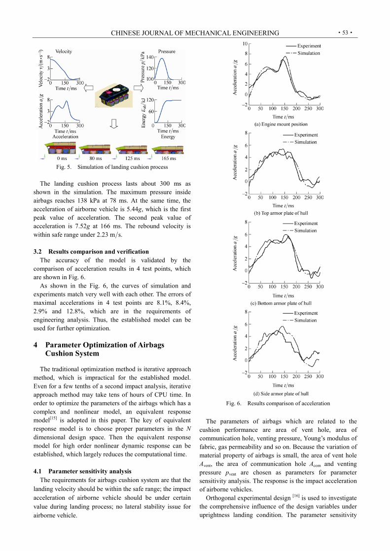
3.2 Results comparison and verification
The accuracy of the model is validated by the comparison of acceleration results in 4 test points, which are shown in Fig. 6.
As shown in the Fig. 6, the curves of simulation and experiments match very well with each other. The errors of maximal accelerations in 4 test points are 8.1%, 8.4%, 2.9% and 12.8%, which are in the requirements of engineering analysis. Thus, the established model can be used for further optimization.
4 Parameter Optimization of Airbags
Cushion System
The traditional optimization method is iterative approach method, which is impractical for the established model. Even for a few tenths of a second impact analysis, iterative approach method may take tens of hours of CPU time. In order to optimize the parameters of the airbags which has a complex and nonlinear model, an equivalent response model[15] is adopted in this paper. The key of equivalent response model is to choose proper parameters in the N dimensional design space. Then the equivalent response model for high order nonlinear dynamic response can be established, which largely reduces the computational time.
4.1 Parameter sensitivity analysis
The requirements for airbags cushion system are that the landing velocity should be within the safe range; the impact acceleration of airborne vehicle should be under certain value during landing process; no lateral stability issue for airborne vehicle.
Fig. 6. Results comparison of acceleration
The parameters of airbags which are related to the
cushion performance are area of vent hole, area of communication hole, venting pressure, Young’s modulus of fabric, gas permeability and so on. Because the variation of material property of airbags is small, the area of vent hole Avent, the area of communication hole Acom and venting pressure pvent are chosen as parameters for parameter sensitivity analysis. The response is the impact acceleration of airborne vehicles.
Orthogonal experimental design [16] is used to investigate the comprehensive influence of the design variables under uprightness landing condition. The parameter sensitivity

WANG Hongyan, et al: Characteristic Verification and Parameter Optimization of Airbags Cushion System for Airborne Vehicle
·54·
analysis results of Avent, Acom and pvent are obtained by standard sensitivity analysis, which are shown in Fig. 7.
Fig. 7. Parameter sensitivity analysis
According to parameter sensitivity analysis, the
contributing percentage due to area of vent hole and area of communication hole is higher than the one due to venting pressure. This result indicates that the area of vent hole and the area of communication hole are the major parameters which affect the response. In practice, the variation of venting pressure is small without extra vent control instruments. Thus the venting pressure is not chosen as design variable in this paper.
4.2 Design variables and the objective
Here the area of vent hole and the area of communication hole are chosen as design variables, while the objective of the optimization is to minimize the maximal acceleration. The maximal allowance pressure inside airbags is set to be constraint for this optimization study to guarantee the material of airbags within the safe range. The proper landing velocity is another constraint to prevent airborne vehicle from rebound and overturn. The constraints of parameter optimization then can be described as follows:
max
r
284 kPa,
3 m/s.
p
v
(5)
In the optimization, the Acom values of the control points
vary from the mean value by 50%. The variation of the Avent value ranges from 75% to 0%, because the initial Avent value is slightly higher than the true value which is indicated by the stronger landing impact. The details of variation range of design variables are listed in Table 1.
Table 1. Design variables and variation range
Design variables
Lower bound (mm2)
Initial value (mm2)
Upper bound (mm2)
Avent 9 860 (75%) 39 440 39 440 (0%) Acom 20 290 (50%) 40 581 60 872 (+50%)
4.3 Establishment of equivalent response model The global approximation model is designed to be
accurately uniform within the parameter range. In this study,
a Latin Hypercube DOE[17] with 40 sampling points is used. Fig. 8 shows the distribution of 40 points for 2 factors.
Fig. 8. Latin Hypercube sampling
The mathematic function which describes the response
curves may affect the accuracy of equivalent response model. Thus Polynomial function and radial basis function[18] are employed to build equivalent response model in order to find the better function.
In general, X(x1, x2, , xn) is n-dimensional input value, y is output response.
Polynomial function can be represented by the following equation:
1 1 2 2( ) ( ) ( ),k ky f X f X f Xβ β β (6)
where iβ is regression coefficient. Analytic equation of radial basis function is
1 1
( ) ( ),p m
ii i i
i i
y f X X Xβ λϕ
(7)
where iβ is regression coefficient, ( )ϕ is basis function, is Euclidean norm, iλ is the weight number of basis
function. The space hood faces built for equivalent response
models are shown in Fig. 9. Fig. 10 illustrates the relative error of equivalent response model at DOE sampling points.
The relative error of the predicted response values shows that the maximum relative error of equivalent response model based on polynomial function is 26.70%. While the root-mean-square error reaches 0.106 2, the maximum relative error of equivalent response model based on radial basis function is dramatically reduced at approx 0.14% and the root-mean-square error is only 8.664 310–7. The combination of Latin Hypercube and radial basis function method has the better capacity to describe the nonlinear characteristic of equivalent response model.
4.4 Results of optimization
The target value is obtained after 147 iterations using simulated annealing algorithm[19]. The optimization iteration history is shown in Fig. 11.

CHINESE JOURNAL OF MECHANICAL ENGINEERING
·55·
Fig. 9. Space hood faces
Fig. 10. Relative error of equivalent response model
Fig. 11. Optimization iteration history
The optimal design variables are: the area of vent hole is
34 709 mm2, and the area of communication hole is 404 64 mm2. The corresponding maximal acceleration of airborne vehicle during landing process is 5.82g, which is largely reduced after optimization.
In order to validate the optimal results based on equivalent response model, the FE model is calculated by the optimal parameters. The maximal acceleration of airborne vehicle obtained by FE model is 6.03g, while the one by equivalent response model is 5.82g. The error for equivalent response model is only 3.51%. The above results indicate that the equivalent response model based on radial basis function is quite accurate for the parameter optimization of airborne vehicles with airbags cushion systems.
4.5 Comparison of airbags cushion characteristics
In order to estimate the improvement of airbags cushion performance, the optimized velocity, acceleration, pressure inside airbags, energy absorption by airbags are compared with the original results.
As illustrated in Fig. 12, the optimized curve of velocity is smoother than original curve. The maximal acceleration of airborne vehicle is decreased by 19.83%. The maximal pressure inside airbags is increased, and the energy absorption performance of airbags is also improved. Table 2 lists the data of optimal results in detail. Overall, the cushion performance of airbags cushion system is obviously improved after optimization, which indicates the optimization method presented in the paper is feasible to such complex nonlinear problem.
5 Conclusions
(1) An FE model of airborne vehicle with airbags
cushion system is established on the basis of volume control model in this paper. The virtual landing cushion process is obtained through simulation. The established model is validated by on-site experiments of vehicle landing. The simulation results agree very well with the experimental results.
(2) In order to optimize the parameters, an equivalent response model is presented. The investigation reveals that the equivalent response model based on Latin Hypercube DOE and radial basis function is nothing less than accurate and can be used for parameter optimization of airbags.

WANG Hongyan, et al: Characteristic Verification and Parameter Optimization of Airbags Cushion System for Airborne Vehicle
·56·
Fig. 12. Comparison of airbags cushion characteristics
Table 2. Data comparison of airbags cushion characteristics
Parameter Rebound velocity
vr(m • s–1)
Maximal acceleration
Amaxg
Maximal pressure inside
airbags pmaxkPa
Energy absorption By airbags
EabkJ
Original 2.23 7.52 138.21 118.25 Optimized 1.90 6.03 142.71 127.54 Variation 0.33 1.49 4.5 9.28
Relative variation r% 14.80 19.83 3.26 7.85
(3) The cushion performance of airbags cushion systems
is largely improved by the optimization. The maximal acceleration of airborne vehicles reduced 19.83%, and energy absorption by airbags increased 7.85% after
optimization.
References [1] TAYLOR A P. Investigation of the application of airbag technology
to provide a softlanding capability for military heavy airdrop[G]. AIAA 2001-2046, 2001: 284–292.
[2] EWING E G, BIXBY H W, KNACKE T W. Recovery system design guide[M]. Beijing: Aviation Industry Press, 1988.
[3] LE Yongxiang. Numerical simulation and optimal design of the process of airbag landing[D]. Changsha: Hunan University, 2010. (in Chinese)
[4] ESGAR J B, MORGAN W C. Analytical study of soft landings on gas-filled bags[R]. NASA Technical Report R-75, Cleveland: Lewis Research Center, 1960.
[5] BROWNING A C. A theoretical approach to air bag shock absorber design[R]. Technical Note No. Mech. Eng. 369, London: Her Majesty’s Stationery Office, 1963.
[6] GARDINIER D J, TAYLOR A P. Design and testing of the K-1 Reusable Launch Vehicle landing system airbags[G]. AIAA 99-1757, 1999: 418–427.
[7] WAN Zhimin, XIE Zhimin. Test research on landing characteristics of aerocraft utilizing airbag as shock absorbers[J]. Test Technology and Testing Machine, 2003, 43(1): 9–12. (in Chinese)
[8] WANG Yawei, YANG Chunxin, KE Peng. Airbag cushion process simulation for cargo airdrop system[J]. Journal of System Simulation, 2007, 19(14): 3 176–3 179. (in Chinese)
[9] WANG J T, NEFSKE J D. A new CAL3D airbag inflation model[G]. SAE Paper No.880654, 1988.
[10] WANG Hongyan, HAO Guixiang. Research on matching and evaluating for recovery system of airborne vehicle based on FEM[C]//The 7th China CAE Annual Conference, Kunming, China, 2011: 120–127. (in Chinese)
[11] NIU Shibo, WANG Hongyan, CHI Baoshan. Optimal design of airbag cushion process for airdropping equipment[J]. Journal of Academy of Armored Force Engineering, 2010, 24(5): 36–40. (in Chinese)
[12] WANG Xucheng. Finite element method[M]. Beijing: Tsinghua University Press, 2003. (in Chinese)
[13] LI Jianyang, WANG Hongyan, HAO Guixiang. Simulation of landing process base on explicit finite element method[J]. Journal of Academy of Armored Force Engineering, 2010, 24(3): 25–28. (in Chinese)
[14] DU Zhiqi, SHAO Pengli. Dynamic finite element simulation of the aluminum alloy hull at landing[J]. ACTA ARMAMENTARⅡ, 2009, 30(1): 1–4. (in Chinese)
[15] MYERS R H, MONTGOMERY D C. Response surface methodology: process and product optimization using designed experiments[M]. New York: John Wiley & Sons, 1976.
[16] ZHANG Yi, LI Yanyan, XU Jinxiang. Research on trajectory parameter optimization based on orthogonal design[J]. Journal of Projectiles, Rockets, Missiles and Guidance, 2008, 28(5): 188–190. (in Chinese)
[17] MCKAY M D, BECKMAN R J, CONOVER W J. A comparison of three methods for selecting values of input variables from a computer code[J]. Technometrics, 1979, 21(2): 239–245.
[18] DOU Yifang, LIU Fei, ZHANG Weihua. Research on comparative analysis is of response surface methods[J]. Journal of Engineering Design, 2007, 14(5): 359–363. (in Chinese)
[19] KIRKPATRICK S, GELATT C D. Optimization by simulated annealing[J]. Science, 1983, 220: 671–680.
Biographical notes WANG Hongyan, born in 1965, is currently a professor at Academy of Armored Force Engineering, China. He received his PhD degree from Jilin University of Technology, China, in 1998.

CHINESE JOURNAL OF MECHANICAL ENGINEERING
·57·
His main research interests include Vehicles Dynamics. E-mail: [email protected] HONG Huangjie, born in 1985, is currently a PhD candidate at Academy of Armored Force Engineering, China. E-mail: [email protected] HAO Guixiang, born in 1980, is currently a PhD candidate at Academy of Armored Force Engineering, China. E-mail: [email protected] DENG Huaxia, born in 1982, is currently a professor at Hefei University of Technology, China. He received his PhD degree
from University of Liverpool, UK, in 2011. His main research interests include dynamic analysis, smart materials and structures. E-mail: [email protected] RUI Qiang, born in 1979, is currently a lecturer at Academy of Armored Force Engineering, China. He received his PhD degree from Academy of Armored Force Engineering, China, in 2009. His main research interests include vehicles structure analysis. E-mail: [email protected] LI Jianyang, born in 1986, is currently a PhD candidate at Academy of Armored Force Engineering, China. E-mail: [email protected]