Embed Size (px)
Citation preview

BiomaterialsScience
PAPER
Cite this: Biomater. Sci., 2022, 10,138
Received 27th October 2021,Accepted 12th November 2021
DOI: 10.1039/d1bm01645h
rsc.li/biomaterials-science
Characterisation of bone regeneration in 3Dprinted ductile PCL/PEG/hydroxyapatite scaffoldswith high ceramic microparticle concentrations†
Chuanliang Cao,a Pengren Huang,b Aruna Prasopthum, ‡c Andrew J. Parsons,d
Fanrong Ai*a and Jing Yang *c
3D printed bioactive glass or bioceramic particle reinforced composite scaffolds for bone tissue engineer-
ing currently suffer from low particle concentration (<50 wt%) hence low osteoconductivity. Meanwhile,
composites with very high inorganic particle concentrations are very brittle. Scaffolds combining high
particle content and ductility are urgently required for bone tissue engineering. Herein, 3D printed PCL/
hydroxyapatite (HA) scaffolds with high ceramic concentration (up to 90 wt%) are made ductile (>100%
breaking strain) by adding poly(ethylene glycol) which is biocompatible and FDA approved. The scaffolds
require no post-printing washing to remove hazardous components. More exposure of HA microparticles
on strut surfaces is enabled by incorporating higher HA concentrations. Compared to scaffolds with
72 wt% HA, scaffolds with higher HA content (90 wt%) enhance matrix formation but not new bone
volume after 12 weeks implantation in rat calvarial defects. Histological analyses demonstrate that bone
regeneration within the 3D printed scaffolds is via intramembranous ossification and starts in the central
region of pores. Fibrous tissue that resembles non-union tissue within bone fractures is formed within
pores that do not have new bone. The amount of blood vessels is similar between scaffolds with mainly
fibrous tissue and those with more bone tissue, suggesting vascularization is not a deciding factor for
determining the type of tissues regenerated within the pores of 3D printed scaffolds. Multinucleated
immune cells are commonly present in all scaffolds surrounding the struts, suggesting a role of managing
inflammation in bone regeneration within 3D printed scaffolds.
1. Introduction
3D printing is a promising manufacturing tool for fabricatingscaffolds for bone tissue engineering.1–4 It offers the ability toprecisely control geometry5,6 and to fabricate stratified struc-tures to mimic the heterogeneity of bone.7 Various materialsincluding bioceramics,8,9 bioactive glasses,10 and bio-degradable polymers11 have been used in 3D printing toproduce degradable bone tissue engineering scaffolds. Thesematerials have a good track record of safety, hence, from a
regulatory point of view, it is relatively easier to translate 3Dprinted scaffolds made of them into the clinic. Whilst ceramicand bioactive glass scaffolds offer relatively high modulus,strength and osteoconductivity,12 their brittleness is a signifi-cant concern for clinical applications.13 Bioceramics and bio-active glasses are intrinsically brittle. They are very sensitive tothe presence of small cracks commonly present in porousscaffolds, and can fail catastrophically when subjected toin vivo forces. The ductility of bone scaffolds is critical for theirmechanical reliability. However, this mechanical property hasreceived less attention compared to modulus and strength. Onthe other hand, although polymers such as biodegradablepolyesters are relatively ductile, they are usually hydrophobicand have poor osteoconductivity and mechanical propertiesinferior to cortical bone.14,15
To overcome limitations associated with single materials,polymer/inorganic composites that mimic, to some extent,bone (which consists of mainly partially carbonated hydroxy-apatite and type I collagen fibrils) have been used in 3D print-ing to combine the ductility of polymers and the osteoconduc-tivity of the inorganic components.1,11,16,17 A balance betweenmechanical properties and osteoconductivity needs to be
†Electronic supplementary information (ESI) available. See DOI: 10.1039/d1bm01645h‡Current address: School of Pharmacy, Walailak University, Nakhon SiThammarat, Thailand, 80160
aSchool of Mechatronic Engineering, Nanchang University, Nanchang, Jiangxi, China
330031. E-mail: [email protected] of Orthopedic Surgery, The Second Affiliated Hospital of Nanchang
University, Nanchang, Jiangxi, China 330006cBiodiscovery Institute, University of Nottingham, Nottingham, UK NG7 2RD.
E-mail: [email protected] Research Group, Faculty of Engineering, University of Nottingham,
Nottingham, UK NG7 2RD
138 | Biomater. Sci., 2022, 10, 138–152 This journal is © The Royal Society of Chemistry 2022
Ope
n A
cces
s A
rtic
le. P
ublis
hed
on 1
7 N
ovem
ber
2021
. Dow
nloa
ded
on 4
/6/2
022
11:5
6:42
AM
. T
his
artic
le is
lice
nsed
und
er a
Cre
ativ
e C
omm
ons
Attr
ibut
ion
3.0
Unp
orte
d L
icen
ce.
View Article OnlineView Journal | View Issue

struck for these composites. Modulus and strength initiallyincrease with the concentration of the inorganic component,subsequently start to plateau before becoming detrimental tothe mechanical properties at very high concentrations.18
Addition of glass or ceramic microparticles into polymers caneven lower strength and increase brittleness of composites atvery low particle concentrations. For example, in a study inwhich the mechanical properties of β-tricalcium phosphate/PCL composites were tested, modulus of the compositesincreased with higher concentrations of the calcium phos-phate particles up to 60 wt%. However, the yield strengths ofall the composites (20 wt% to 60 wt%) were lower than purePCL.19 These studies have demonstrated that although highconcentrations of glass/ceramic particles can increasemodulus, they can also make the composites more brittle withlow strength. As a consequence, the inorganic component istypically kept at relatively low concentration (<50 wt%).20 Onthe other hand, higher concentration of the inorganic com-ponent is desirable to increase osteoconductivity.21 Low con-centration of the inorganic component in the compositesleads to less exposure of them on the surface, which compro-mises their osteoconductivity as most of them are embeddedin the polymer matrix hence not in contact with cells. Theosteoconductive properties of bioactive glasses with certaincompositions and some calcium phosphates have long beendocumented. Some studies even showed osteoinductive pro-perties of these materials, although conflicting data on thisexist in the literature.22 The formation of carbonate hydroxy-apatite on the material surfaces as well as released ions due todissolution have been demonstrated to be key for their goodosteogenic properties.23 It is reasonable to postulate that if theglass or ceramic particles are not present on the strut surfaceof 3D printed scaffolds, their osteoconductive/osteoinductiveproperties will be compromised. Only few efforts have beenmade to make composites with high-concentration inorganiccomponent more flexible in which 3D printed scaffolds withhigh-concentration hydroxyapatite (HA) micro particles (up to90 wt%) were made elastic and ductile by adding a surfactant(2-butoxyethanol) and a plasticizer (Dibutyl phthalate).24
However, the inclusion of these additives may have impli-cations in safety and regulation.25
Bone regenerates either via intramembranous ossificationor by endochondral ossification.26 Intramembranous ossifica-tion, which is responsible for the formation of most flatbones, involves the differentiation of mesenchymal cells toosteoblasts, the formation of ossification centres and initialsynthesis of collagen fibrils followed by polarized secretion ofbone matrix.27 In endochondral ossification, which is respon-sible for the formation of long bones, cartilage forms firstbefore being replaced by bone.28 Bone regeneration via endo-chondral ossification has been considered to be advantageousfor biomaterial scaffolds supplemented with stem/progenitorcells due to the requirement of initial vascularization that iscritical for cell survival.29–31 It will be useful to characterise theroute of bone formation for the analysis of in vivo bone regen-eration within 3D printed scaffolds.
Herein, 3D printed PCL/PEG/HA composites with high con-centrations (up to 90 wt%) of HA particles were renderedductile by adding poly(ethylene glycol) (PEG). PEG is an FDA-approved biomaterial that has shown goodbiocompatibility.32,33 The optimal molecular weight and con-centration of PEG added to the 3D printing ink formulationwere identified for achieving ductility. The mechanical pro-perties of individual struts and scaffolds with different HAconcentrations were measured. Bone formation within the 3Dprinted scaffolds were tested in vivo using a rat calvarialmodel. These 3D printed scaffolds are potentially applicable toclinical applications that require ductile and surgically trim-mable materials.
2. Materials and methods2.1 Strut and scaffold fabrication
Polycaprolactone (PCL, Mn = 80 000 g mol−1), poly(ethyleneglycol) (PEG, Mn = 400, 3350, 20 000 Da) and hydroxyapatitemicroparticles (product number 289396) were all purchasedfrom Sigma-Aldrich (UK). The size distribution of the hydroxy-apatite microparticles is shown in Fig. S1.† Various formu-lations of PCL/PEG/HA were made by first dissolving PEG in di-chloromethane (DCM), then adding HA microparticles andvortexed until homogeneous, lastly adding PCL and agitatingthe mixture on a roller overnight. All struts and scaffolds weremade using a pneumatic extrusion-based 3D printer(RegenHU, Switzerland) at room temperature in air using aconical needle with a nozzle diameter of 260 μm. The individ-ual struts were extruded at a pressure of 4 bar and then col-lected in a tray 10–15 cm below the needle. Scaffolds were fab-ricated by extrusion-based 3D printing using a pressure of 4–6bar and a printing speed of 12–20 mm s−1. After the printingprocess, all the individual struts and scaffolds were dried inair for 24 hours at room temperature to eliminate the residualsolvent (DCM).
2.2 Mechanical property testing
Single strut tensile testing was performed using a sensitivetensile test facility (LEX810, Diastron Ltd, UK) (Fig. S2†). Strutswere fixed individually onto the plastic tabs with a 10 mmgauge length setup. Prior to testing, the diameters of the fibreswere measured using an optical microscope. And the sampleswere stretched to 400% strain at a crosshead speed of 0.04 mms−1 at room temperature in air. Compression testing ofscaffolds was performed using a universal texture analyser(TA-HD Plus, Stable Microsystems, USA). The scaffolds (24layers), with dimensions of 8 (width) × 8 (width) × 4.3 (height)mm3, were compressed in the height direction with a speed of0.03 mm s−1 to the strain of 60%. The compressive moduluswas calculated from the initial linear range of the stress–straincurves (strain range 1% to 5%). At least three specimens weretested for each sample group. Tensile testing was carried outusing a universal testing machine with a 10 kN load cell(CMT6104, Mets Industrial Systems Co., Ltd) at a rate of
Biomaterials Science Paper
This journal is © The Royal Society of Chemistry 2022 Biomater. Sci., 2022, 10, 138–152 | 139
Ope
n A
cces
s A
rtic
le. P
ublis
hed
on 1
7 N
ovem
ber
2021
. Dow
nloa
ded
on 4
/6/2
022
11:5
6:42
AM
. T
his
artic
le is
lice
nsed
und
er a
Cre
ativ
e C
omm
ons
Attr
ibut
ion
3.0
Unp
orte
d L
icen
ce.
View Article Online

0.17 mm s−1. Scaffolds (6 layers) used in the tensile testinghad dimensions of 20 × 10 × 1 mm3.
2.3 Scanning electron microscope (SEM)
SEM images were obtained by using a JSM-6490 scanning elec-tron microscope (JEOL, UK). Scaffold samples were mountedon stubs and sputter coated with gold/palladium beforeimaging. For cell-laden scaffolds, the specimens were fixed in2.5% (v/v) glutaraldehyde/PBS and stained with 1%(v/v)osmium tetroxide prior to dehydration.
2.4 In vitro cell culture
The human mesenchymal stem cells (hMSCs) (TCS Cellworks,UK) were immortalised according to a previous protocol.34 Thecells were expanded in Dulbecco’s modified Eagle’s (DMEM)medium with 10% (v/v) FBS, 1% (v/v) L-glutamine, 1% (v/v) 1%(v/v) antibiotic/antimycotic (AB/AM) solution and 1% (v/v) non-essential amino acids. The scaffolds were sterilised in 70%(v/v) ethanol for 1 hour, washed with PBS and incubated inDMEM medium containing 10% (v/v) FBS before cell seeding.1 × 106 cells were seeded into each 3D printed PCL/HA scaffold(1 × 1 × 0.5 cm3). The osteogenic differentiation medium(αMEM with 10% (v/v) FBS, 1% (v/v) L-glutamine and 1% (v/v)antibiotic/antimycotic solution, 10 mM β-glycerophosphate,100 nM dexamethasone) was then added after initial attach-ment of cells to the scaffolds. The hMSC-seeded scaffolds werecultured for 21 days during which the osteogenic differen-tiation medium was changed twice a week.
hMSC-seeded scaffolds that were cultured in the osteogenicdifferentiation medium were harvested at different days (day 1,day 7, day 14, and day 21). They were individually washed withice-cold PBS, homogenised in a lysis buffer containing theHalt™ protease inhibitor cocktail (Thermo Fisher Scientific,UK), and freeze-thawed for three cycles to promote cell lysis.The clear supernatants were then used to measure the quantityof DNA and osteocalcin (a late marker of osteogenesis) usingPicoGreen™ and an enzyme-linked immunosorbent assay kit(Thermo Fisher Scientific, UK), respectively. All samples andstandards were performed in triplicate. The cell-free scaffoldswere used as negative controls.
2.5 In vivo testing of scaffolds in rat calvarial defects
The rat calvarial defect model was established on six 8-weekold male Spraguee Dawley rats provided by Jiangxi Universityof Traditional Chinese Medicine (Nanchang, China). Each ratweighted approximately 200 g. All animal procedures were per-formed in accordance with the guidelines for care and use oflaboratory animals of Nanchang University and approved bythe Animal Ethics Committee of the Second Affiliated Hospitalof Nanchang University. Briefly, the rats were anesthetizedwith 10% chloral hydrate (4 ml kg−1), and the skin of the surgi-cal site was shaved. The rats were fixed on the operating tableand iodophor was used to disinfect the skin of the surgicalsite. A longitudinal incision about 3 cm long was made alongthe sagittal line of the skull to expose the skull. Two calvarialdefects with a diameter of 5 mm were drilled on both sides of
parietal bone with a surgical trephine (Fig. S3†). Rat calvarialdefects with 5 mm diameter have been widely used as a boneregeneration model though it may not be considered as criti-cal-sized defects.35,36 5 mm defect size allowed the introduc-tion of two defects per rat and the avoidance of the sagittalsuture spanning the defect. The operation site was continu-ously rinsed with saline to reduce heat during drilling. Twodifferent scaffold groups (72% HA and 90% HA) were sterilizedby ethylene oxide before being implanted into the defect sites.Six samples were used for each group of scaffolds and twodifferent scaffolds were implanted in a rat. Incisions were thensutured. After waking up, the rats were moved into a cleananimal room. All the experimental animals were in good con-dition and no wound infection was identified. The scaffoldsused for implantation were 5 mm in diameter and werepunched out from printed scaffolds (mean pore size – 380 μm,strut diameter – 280 μm, porosity – 67% (pores between struts)and 7 layers).
2.6 Gross morphology and micro-CT
After 12 weeks, the animals were sacrificed under generalanesthesia, and the specimens were retrieved with some sur-rounding host bone and fixed with 10% formalin. Gross mor-phology images were taken using an optical microscope(A005+, Shenzhen SuperEye Technology, China). The fixedspecimens were scanned with custom made Micro-CT (XidianUniversity, Shaanxi, China) with a tube voltage of 78 kV and atube current of 100 μA. After scanning, a software for isosur-face rendering (3D Med 5.0, Chinese Academy of Sciences) wasused for 3D reconstruction to evaluate the degree ofmineralization.
2.7 Histological analysis
Following Micro-CT analysis, the scaffolds were decalcified in0.5 M EDTA decalcifying solution for 30 days with frequentchanging of the solution every 2–3 days. The specimens werethen embedded in paraffin blocks, and transversal slices with4 µm thickness were cut from the middle of each defect usinga microtome. The slices were then washed in xylene to removeparaffin followed by rehydration in ethanol series and waterbefore being stained with hematoxylin and eosin (H&E). Forimmunohistochemistry, the slices were firstly dewaxed in thesame way as those used for H&E staining. They were then incu-bated in 3% hydrogen peroxide solution followed by 3%bovine serum albumin to block endogenous peroxidase andnon-specific binding, respectively, before being incubated withprimary anti-Collagen II or anti-osteocalcin (OCN) antibodies.The slices were then washed and incubated in secondary anti-bodies tagged with horseradish peroxidase followed by beingstained in 3,3′-diaminobenzidine chromogenic solution toproduce a brown colour where collagen II or OCN was present.All reagents used for histology were from Wuhan ServicebioTechnology, China. All images were obtained by an opticalmicroscope (NIKON Eclipse Ci, Japan). Eosin-stained area wasmeasured by using the colour deconvolution function inImageJ with the same threshold range for all images (National
Paper Biomaterials Science
140 | Biomater. Sci., 2022, 10, 138–152 This journal is © The Royal Society of Chemistry 2022
Ope
n A
cces
s A
rtic
le. P
ublis
hed
on 1
7 N
ovem
ber
2021
. Dow
nloa
ded
on 4
/6/2
022
11:5
6:42
AM
. T
his
artic
le is
lice
nsed
und
er a
Cre
ativ
e C
omm
ons
Attr
ibut
ion
3.0
Unp
orte
d L
icen
ce.
View Article Online
Institutes of Health, USA). The quantification of collagen IIand OCN area was carried out using the IHC plugin in ImageJas described before.37
2.8 Statistical analysis
All data were presented as mean ± standard deviation (SD).Statistical analysis was performed on GraphPad Prism 5 soft-ware (Minitab Inc., State College, PA, USA) using one-way ana-lysis of variance (ANOVA) to test for significance. Post hocTukey’s multiple-comparison test was used to determine theindividual differences among the groups. Unpaired T test wasused when there were only two groups compared.
3. Results3.1 Effects of PEG concentration and molecular weight onthe mechanical properties of struts and scaffolds
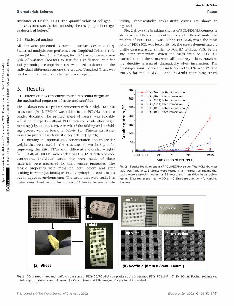
Fig. 1 shows two 3D printed structures with a high HA : PCLmass ratio (9 : 1). PEG400 was added to the PCL/HA blend torender ductility. The printed sheet (4 layers) was foldablewhilst counterparts without PEG fractured easily after slightbending (Fig. 1a, Fig. S4†). A movie of the folding and unfold-ing process can be found in Movie S1.† Thicker structureswere also printable with satisfactory fidelity (Fig. 1b).
To identify the optimal PEG concentration and molecularweight that were used in the structures shown in Fig. 1 forimproving ductility, PEGs with different molecular weights(400, 3350, 20 000 Da) were added to PCL/HA at different con-centrations. Individual struts that were made of thesematerials were measured for their tensile properties. Thetensile properties were measured both before and aftersoaking in water (24 hours) as PEG is hydrophilic and leachesout in aqueous environments. The struts that were soaked inwater were dried in air for at least 24 hours before tensile
testing. Representative stress–strain curves are shown inFig. S5.†
Fig. 2 shows the breaking strains of PCL/PEG/HA compositestruts with different concentrations and different molecularweights of PEG. For PEG20000 and PEG3350, when the massratio of PEG : PCL was below 10 : 10, the struts demonstrated abrittle characteristic, similar to PCL/HA without PEG, beforeand after immersion. When the mass ratio of PEG : PCLreached 10 : 10, the struts were still relatively brittle. However,the ductility increased dramatically after immersion. Thebreaking strains increased from 6.2% and 12.1% to 47.9% and190.5% for the PEG(3350) and PEG(20k) containing struts,
Fig. 1 3D printed sheet and scaffold consisting of PEG400/PCL/HA composite struts (mass ratio PEG : PCL : HA = 7 : 10 : 90). (a) Rolling, folding andunfolding of a printed sheet (4 layers). (b) Gross views and SEM images of a printed thick scaffold.
Fig. 2 Tensile breaking strain of PCL/PEG/HA struts. The PCL : HA massratio was fixed at 1 : 9. Struts were tested in air. Immersion means thatstruts were soaked in water for 24 hours and then dried in air beforetesting. Data represent mean ± SD, n = 5. Lines are used only for guidingthe eyes.
Biomaterials Science Paper
This journal is © The Royal Society of Chemistry 2022 Biomater. Sci., 2022, 10, 138–152 | 141
Ope
n A
cces
s A
rtic
le. P
ublis
hed
on 1
7 N
ovem
ber
2021
. Dow
nloa
ded
on 4
/6/2
022
11:5
6:42
AM
. T
his
artic
le is
lice
nsed
und
er a
Cre
ativ
e C
omm
ons
Attr
ibut
ion
3.0
Unp
orte
d L
icen
ce.
View Article Online
respectively. For struts with PEG(400), the ductility of strutsincreased at lower PEG : PCL ratios, indicating better plasticiz-ing effect of PEG400. The ductility of struts with PEG400 wasbetter before immersion in contrast to those with higher mole-cular weight PEGs. When the mass ratio of PEG400 : PCLreached 7 : 10, the breaking strain was 260.9% and reduced to121.2% after immersion but still ductile.
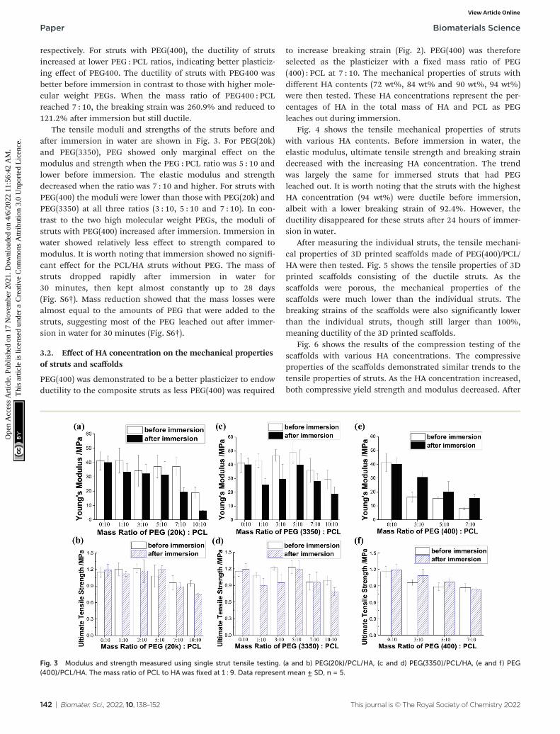
The tensile moduli and strengths of the struts before andafter immersion in water are shown in Fig. 3. For PEG(20k)and PEG(3350), PEG showed only marginal effect on themodulus and strength when the PEG : PCL ratio was 5 : 10 andlower before immersion. The elastic modulus and strengthdecreased when the ratio was 7 : 10 and higher. For struts withPEG(400) the moduli were lower than those with PEG(20k) andPEG(3350) at all three ratios (3 : 10, 5 : 10 and 7 : 10). In con-trast to the two high molecular weight PEGs, the moduli ofstruts with PEG(400) increased after immersion. Immersion inwater showed relatively less effect to strength compared tomodulus. It is worth noting that immersion showed no signifi-cant effect for the PCL/HA struts without PEG. The mass ofstruts dropped rapidly after immersion in water for30 minutes, then kept almost constantly up to 28 days(Fig. S6†). Mass reduction showed that the mass losses werealmost equal to the amounts of PEG that were added to thestruts, suggesting most of the PEG leached out after immer-sion in water for 30 minutes (Fig. S6†).
3.2. Effect of HA concentration on the mechanical propertiesof struts and scaffolds
PEG(400) was demonstrated to be a better plasticizer to endowductility to the composite struts as less PEG(400) was required
to increase breaking strain (Fig. 2). PEG(400) was thereforeselected as the plasticizer with a fixed mass ratio of PEG(400) : PCL at 7 : 10. The mechanical properties of struts withdifferent HA contents (72 wt%, 84 wt% and 90 wt%, 94 wt%)were then tested. These HA concentrations represent the per-centages of HA in the total mass of HA and PCL as PEGleaches out during immersion.
Fig. 4 shows the tensile mechanical properties of strutswith various HA contents. Before immersion in water, theelastic modulus, ultimate tensile strength and breaking straindecreased with the increasing HA concentration. The trendwas largely the same for immersed struts that had PEGleached out. It is worth noting that the struts with the highestHA concentration (94 wt%) were ductile before immersion,albeit with a lower breaking strain of 92.4%. However, theductility disappeared for these struts after 24 hours of immer-sion in water.
After measuring the individual struts, the tensile mechani-cal properties of 3D printed scaffolds made of PEG(400)/PCL/HA were then tested. Fig. 5 shows the tensile properties of 3Dprinted scaffolds consisting of the ductile struts. As thescaffolds were porous, the mechanical properties of thescaffolds were much lower than the individual struts. Thebreaking strains of the scaffolds were also significantly lowerthan the individual struts, though still larger than 100%,meaning ductility of the 3D printed scaffolds.
Fig. 6 shows the results of the compression testing of thescaffolds with various HA concentrations. The compressiveproperties of the scaffolds demonstrated similar trends to thetensile properties of struts. As the HA concentration increased,both compressive yield strength and modulus decreased. After
Fig. 3 Modulus and strength measured using single strut tensile testing. (a and b) PEG(20k)/PCL/HA, (c and d) PEG(3350)/PCL/HA, (e and f) PEG(400)/PCL/HA. The mass ratio of PCL to HA was fixed at 1 : 9. Data represent mean ± SD, n = 5.
Paper Biomaterials Science
142 | Biomater. Sci., 2022, 10, 138–152 This journal is © The Royal Society of Chemistry 2022
Ope
n A
cces
s A
rtic
le. P
ublis
hed
on 1
7 N
ovem
ber
2021
. Dow
nloa
ded
on 4
/6/2
022
11:5
6:42
AM
. T
his
artic
le is
lice
nsed
und
er a
Cre
ativ
e C
omm
ons
Attr
ibut
ion
3.0
Unp
orte
d L
icen
ce.
View Article Online

immersion, the compressive yield strength and modulusincreased, especially for the 90% HA scaffolds which increasedfrom 0.35 MPa and 2.64 MPa to 0.82 MPa and 18.31 MPa foryield strength and modulus, respectively. The increase inmodulus of the scaffolds after immersion was consistent withwhat was observed for the struts with PEG(400).
3.3 Morphology of PCL/PEG/HA struts with different HAconcentrations
Fig. 7 shows the SEM images of PCL/PEG(400)/HA scaffoldswith various HA concentrations (72 wt%, 84 wt%, 90 wt%, and94 wt%). The surface of the 72% HA scaffold was relativelysmoother than the others with some HA micro particles visibleon the strut surface. There seemed to be more presence of HAparticles in the 72% HA scaffolds after immersion in water. Asthe HA concentration increased, there was significantly moreexposure of the HA particles. The levels of HA exposure for the84%, 90% and 94% HA scaffolds were similar. There werevisible pores between the HA particles in the struts when theHA concentration was higher than 72%. Besides the poresbetween the HA particles, microscopic pores were visiblewithin the polymer matrix for the 84% HA and 90% HAscaffolds (Fig. 7 insets). These pores might be due to the phaseseparation between PCL and PEG.38 However, the 94% HAscaffold showed no sign of pores within the polymer matrix,possibly due to the very small amount of PCL and PEG in thecomposite.
3.4 In vitro osteogenic differentiation and In vivo boneregeneration in rat calvarial defects
We first characterized in vitro osteogenic differentiation ofhuman mesenchymal stem cells within three different 3D
Fig. 4 Breaking strain, Young’s modulus and Ultimate tensile strength of the PCL/PEG400/HA struts (mass ratio PEG(400) : PCL = 7 : 10) withdifferent HA concentrations. Data represent mean ± SD, n = 5. * indicates p < 0.05, ** indicates p < 0.01 and *** indicates p < 0.001.
Fig. 5 Tensile properties of 3D printed scaffolds (6 layers) consisting of ductile struts. Data represent mean ± SD, n = 4. * indicates p < 0.05, ** indi-cates p < 0.01 and *** indicates p < 0.001.
Fig. 6 Compression modulus and yield strength of PCL/PEG(400)/HAscaffolds with different HA concentrations. Data represent mean ± SD, n= 3. Lines are used only for guiding the eyes.
Biomaterials Science Paper
This journal is © The Royal Society of Chemistry 2022 Biomater. Sci., 2022, 10, 138–152 | 143
Ope
n A
cces
s A
rtic
le. P
ublis
hed
on 1
7 N
ovem
ber
2021
. Dow
nloa
ded
on 4
/6/2
022
11:5
6:42
AM
. T
his
artic
le is
lice
nsed
und
er a
Cre
ativ
e C
omm
ons
Attr
ibut
ion
3.0
Unp
orte
d L
icen
ce.
View Article Online

Fig. 7 SEM images of PCL/PEG(400)/HA scaffolds with varied HA concentrations. Insets show the high-magnification images of strut surfaces. Thescale bars in insets are 10 μm.
Paper Biomaterials Science
144 | Biomater. Sci., 2022, 10, 138–152 This journal is © The Royal Society of Chemistry 2022
Ope
n A
cces
s A
rtic
le. P
ublis
hed
on 1
7 N
ovem
ber
2021
. Dow
nloa
ded
on 4
/6/2
022
11:5
6:42
AM
. T
his
artic
le is
lice
nsed
und
er a
Cre
ativ
e C
omm
ons
Attr
ibut
ion
3.0
Unp
orte
d L
icen
ce.
View Article Online
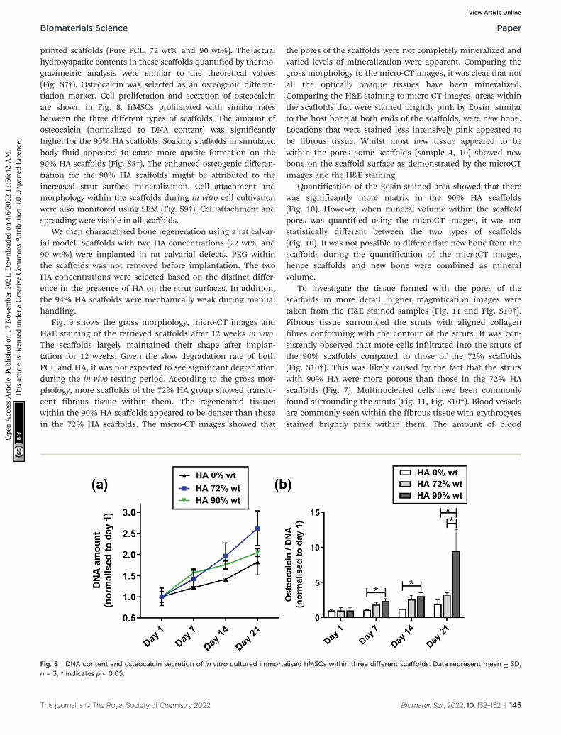
printed scaffolds (Pure PCL, 72 wt% and 90 wt%). The actualhydroxyapatite contents in these scaffolds quantified by thermo-gravimetric analysis were similar to the theoretical values(Fig. S7†). Osteocalcin was selected as an osteogenic differen-tiation marker. Cell proliferation and secretion of osteocalcinare shown in Fig. 8. hMSCs proliferated with similar ratesbetween the three different types of scaffolds. The amount ofosteocalcin (normalized to DNA content) was significantlyhigher for the 90% HA scaffolds. Soaking scaffolds in simulatedbody fluid appeared to cause more apatite formation on the90% HA scaffolds (Fig. S8†). The enhanced osteogenic differen-tiation for the 90% HA scaffolds might be attributed to theincreased strut surface mineralization. Cell attachment andmorphology within the scaffolds during in vitro cell cultivationwere also monitored using SEM (Fig. S9†). Cell attachment andspreading were visible in all scaffolds.
We then characterized bone regeneration using a rat calvar-ial model. Scaffolds with two HA concentrations (72 wt% and90 wt%) were implanted in rat calvarial defects. PEG withinthe scaffolds was not removed before implantation. The twoHA concentrations were selected based on the distinct differ-ence in the presence of HA on the strut surfaces. In addition,the 94% HA scaffolds were mechanically weak during manualhandling.
Fig. 9 shows the gross morphology, micro-CT images andH&E staining of the retrieved scaffolds after 12 weeks in vivo.The scaffolds largely maintained their shape after implan-tation for 12 weeks. Given the slow degradation rate of bothPCL and HA, it was not expected to see significant degradationduring the in vivo testing period. According to the gross mor-phology, more scaffolds of the 72% HA group showed translu-cent fibrous tissue within them. The regenerated tissueswithin the 90% HA scaffolds appeared to be denser than thosein the 72% HA scaffolds. The micro-CT images showed that
the pores of the scaffolds were not completely mineralized andvaried levels of mineralization were apparent. Comparing thegross morphology to the micro-CT images, it was clear that notall the optically opaque tissues have been mineralized.Comparing the H&E staining to micro-CT images, areas withinthe scaffolds that were stained brightly pink by Eosin, similarto the host bone at both ends of the scaffolds, were new bone.Locations that were stained less intensively pink appeared tobe fibrous tissue. Whilst most new tissue appeared to bewithin the pores some scaffolds (sample 4, 10) showed newbone on the scaffold surface as demonstrated by the microCTimages and the H&E staining.
Quantification of the Eosin-stained area showed that therewas significantly more matrix in the 90% HA scaffolds(Fig. 10). However, when mineral volume within the scaffoldpores was quantified using the microCT images, it was notstatistically different between the two types of scaffolds(Fig. 10). It was not possible to differentiate new bone from thescaffolds during the quantification of the microCT images,hence scaffolds and new bone were combined as mineralvolume.
To investigate the tissue formed with the pores of thescaffolds in more detail, higher magnification images weretaken from the H&E stained samples (Fig. 11 and Fig. S10†).Fibrous tissue surrounded the struts with aligned collagenfibres conforming with the contour of the struts. It was con-sistently observed that more cells infiltrated into the struts ofthe 90% scaffolds compared to those of the 72% scaffolds(Fig. S10†). This was likely caused by the fact that the strutswith 90% HA were more porous than those in the 72% HAscaffolds (Fig. 7). Multinucleated cells have been commonlyfound surrounding the struts (Fig. 11, Fig. S10†). Blood vesselsare commonly seen within the fibrous tissue with erythrocytesstained brightly pink within them. The amount of blood
Fig. 8 DNA content and osteocalcin secretion of in vitro cultured immortalised hMSCs within three different scaffolds. Data represent mean ± SD,n = 3. * indicates p < 0.05.
Biomaterials Science Paper
This journal is © The Royal Society of Chemistry 2022 Biomater. Sci., 2022, 10, 138–152 | 145
Ope
n A
cces
s A
rtic
le. P
ublis
hed
on 1
7 N
ovem
ber
2021
. Dow
nloa
ded
on 4
/6/2
022
11:5
6:42
AM
. T
his
artic
le is
lice
nsed
und
er a
Cre
ativ
e C
omm
ons
Attr
ibut
ion
3.0
Unp
orte
d L
icen
ce.
View Article Online

vessels was comparable between the two types of scaffoldswhen vessel areas were quantified in the H&E staining images(Fig. 11c). 70% HA scaffolds which mostly had fibrous tissueswithin the pores also contained a good amount of bloodvessels (Fig. 11b).
As some tissue within the 90% HA scaffolds that were opti-cally dense but not mineralized resembled cartilage, in con-
junction with the aim to identify the route of bone formation,expression of collagen II (chondrogenic markers) was analysedusing immunohistochemistry (Fig. 12). In general, the level ofcollagen II presence within the scaffold was low. In addition,collagen II was not evenly distributed in the tissue within thepores (Fig. 12, Fig. S11†). Some areas showed relatively moreintensive staining of collagen II, which might be an indication
Fig. 9 Image of scaffolds after 12-week implantation in rat calvarial defects. Row 1&2 – Gross morphology of retrieved scaffolds. Row 3&4 –
MicroCT images of the scaffolds. Row 5&6 – H&E staining (pink staining) of transverse cross-sectional slices of the scaffolds. Six samples weretested for each scaffold composition. Scale bars are 2 mm.
Fig. 10 Mineral volume (including both new bone and scaffold) and quantified matrix area (Eosin stained) within scaffolds. * denotes p < 0.05, Datarepresent mean ± SD, n = 6.
Paper Biomaterials Science
146 | Biomater. Sci., 2022, 10, 138–152 This journal is © The Royal Society of Chemistry 2022
Ope
n A
cces
s A
rtic
le. P
ublis
hed
on 1
7 N
ovem
ber
2021
. Dow
nloa
ded
on 4
/6/2
022
11:5
6:42
AM
. T
his
artic
le is
lice
nsed
und
er a
Cre
ativ
e C
omm
ons
Attr
ibut
ion
3.0
Unp
orte
d L
icen
ce.
View Article Online
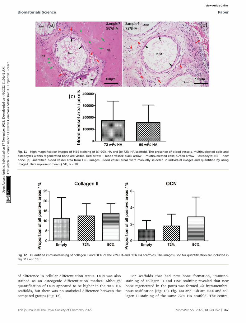
of difference in cellular differentiation status. OCN was alsostained as an osteogenic differentiation marker. Althoughquantification of OCN appeared to be higher in the 90% HAscaffolds, but there was no statistical difference between thecompared groups (Fig. 12).
For scaffolds that had new bone formation, immuno-staining of collagen II and H&E staining revealed that newbone regenerated in the pores was formed via intramembra-nous ossification (Fig. 13). Fig. 13a and 13b are H&E and col-lagen II staining of the same 72% HA scaffold. The central
Fig. 11 High magnification images of H&E staining of (a) 90% HA and (b) 72% HA scaffold. The presence of blood vessels, multinucleated cells andosteocytes within regenerated bone are visible. Red arrow – blood vessel; black arrow – multinucleated cells; Green arrow – osteocyte; NB – newbone. (c) Quantified blood vessel area from H&E images. Blood vessel areas were manually selected in individual images and quantified by usingImageJ. Date represent mean ± SD, n = 18.
Fig. 12 Quantified immunostaining of collagen II and OCN of the 72% HA and 90% HA scaffolds. The images used for quantification are included inFig. S12 and 13.†
Biomaterials Science Paper
This journal is © The Royal Society of Chemistry 2022 Biomater. Sci., 2022, 10, 138–152 | 147
Ope
n A
cces
s A
rtic
le. P
ublis
hed
on 1
7 N
ovem
ber
2021
. Dow
nloa
ded
on 4
/6/2
022
11:5
6:42
AM
. T
his
artic
le is
lice
nsed
und
er a
Cre
ativ
e C
omm
ons
Attr
ibut
ion
3.0
Unp
orte
d L
icen
ce.
View Article Online

region of the eosin stained new bone showed absence of col-lagen II (Fig. 13d and e). The presence of collagen II was mostintensive in areas that immediately surrounded the new bone(Fig. 13d–f ). The morphology of the new bone tissue rep-resents the process of bone formation via intramembranousossification in which mesenchymal cells condense and differ-entiate to osteoblasts that secret osteoid (Fig. 13d inset).27
4 Discussion
This study aimed to test: (1) the effectiveness of PEG onendowing ductility to PCL/HA composites with high HA con-centrations; (2) how the level of HA exposure on strut surface
affects bone regeneration; and (3) the route of bone regener-ation within the pores (pores between struts) of the 3D printedscaffolds in vivo. PEG was chosen because of its biocompatibil-ity and demonstrated plasticizing effect on polymers.39,40 Inthis study, PCL/PEG/HA composites with high HA contentswere endowed with ductility by adding PEG alone, whichmeans there is no need to wash the scaffolds after printing toremove hazardous additives. In addition, our previous datashowed that residual DCM in 3D printed scaffolds can evapor-ate to safe levels in air.41
PEG with lower molecular weight (400 Da) was shown to bea better plasticizer as the ductility of struts (increased breakingstrain) was achieved with a lower concentration. One studyreported the effect of the molecular weight of PEG on the
Fig. 13 H&E staining and immunostaining of collagen II (brown). (a) H&E staining and (b) Immunostaining of collagen II of the same 72% HAscaffold showing tissue formed within the pores. (c–e) are high-magnification images of the areas within the dashed boxes. Inset in (d) is a sche-matic of intramembranous ossification. (f ) Immunostaining of collagen II of a 90% HA scaffold. Blue arrow−cells morphologically resemble osteo-blasts; Green arrow – osteocyte; Yellow arrow – fibrous tissue; Red arrow – blood vessel; NB – new bone; HB – host bone.
Paper Biomaterials Science
148 | Biomater. Sci., 2022, 10, 138–152 This journal is © The Royal Society of Chemistry 2022
Ope
n A
cces
s A
rtic
le. P
ublis
hed
on 1
7 N
ovem
ber
2021
. Dow
nloa
ded
on 4
/6/2
022
11:5
6:42
AM
. T
his
artic
le is
lice
nsed
und
er a
Cre
ativ
e C
omm
ons
Attr
ibut
ion
3.0
Unp
orte
d L
icen
ce.
View Article Online

toughness of PCL/PEG/Starch blends, which showed anoptimal molecular weight of 3400 Da (when compared against400, 8000 and 100 000 Da) for maximum toughness and break-ing strain.42 However, this three-component blend is differentfrom the ones in our study, and the toughness depended onthe interaction between the three components and the inter-action between PEG(400) and PCL was shielded by starch.
Instead of a gradual increase of ductility with increasingPEG content as reported before,40 our results showed a dra-matic increase in ductility after reaching a threshold ofPEG : PCL ratio which is molecular weight dependent (7 : 10for PEG(400), 10 : 10 for PEG(3350) and PEG(20k)). For strutswith PEG(3350) and PEG(20k) which are solid at room temp-erature, ductility was obtained only after the struts wereimmersed in water. The increase in ductility after immersionmay be attributed to the removal of brittle PEG-rich domainswhich might be formed as a result of the phase separationbetween PEG and PCL.38 It was found that the ductility waslargely maintained or improved even after most PEG leachedout after immersion (Fig. 2, Fig. S5†). Interestingly when a rela-tively small amount of PEG was added (PEG : PCL < 5 : 10), theincrease in failure strain was marginal. This may be due tothat the free volume created by the plasticizer (PEG) was stillpresent after the leaching out of PEG.43 Indeed, ductility dis-appeared after annealing the struts which removed the freevolume created by the addition of PEG (Fig. S14†).
In general, the elastic modulus and strength of the strutsand scaffolds decreased with increasing HA content (Fig. 4–6).This is likely due to the decreasing amount of PCL matrixwhich binds the particles together and consequently thereduced ability in transferring load from the polymer matrix tothe HA particles.44 It was clear from the SEM images thathigher concentration of HA particles in the struts resulted inmore apparent exposure of them on the strut surface, particu-larly when the concentration was higher than 70 wt% (Fig. 7).The trade-off between mechanical properties and the amountof exposed HA particles on the strut surface led us to study theeffect of HA concentration on the formation of bone in vivo toidentify if high-concentration HA is beneficial for bone for-mation. The in vivo data demonstrated that more HA exposureon strut surface (90% HA scaffolds) enhanced matrix for-mation within the pores, but not mineral volume compared tothe 72% HA scaffolds. Previous studies have reported ben-eficial effect of higher ceramic concentration on osteogenesis.However, the reported ceramic concentrations were lower thanthe ones studied here.45 The long-term effect of high HA con-centration on bone regeneration requires further investigation.It is worth noting that the strut topography was differentbetween the two types of scaffolds. There is ample evidencethat topography affects the differentiation of mesenchymalstem cells in vitro.46 However, effect of topography on boneregeneration in vivo is less clear47 though improved osseointe-gration associated with implant surface roughness has beenreported before.48 Although the compressive mechanical pro-perties of the scaffolds are inferior to cortical bones, they arewithin the lower end of the mechanical property range of can-
cellous bone.49,50 It is envisaged that the 3D printed ductilescaffolds could be used in non-load bearing applications forbone regeneration. For them to be used in load-bearing appli-cations, innovative ways of mechanically reinforcing thesehigh-inorganic-concentration struts will need to be explored inthe future.
Histological analyses (H&E staining,Immunohistochemistry of collagen II) were carried out tostudy the tissues formed within the pores in more detail andto exam the route of bone formation within 3D printedscaffolds, which is under-investigated. Moreover, a recentstudy reported endochondral ossification induced by alignedpores within collagen sponges which have some level of resem-blance to the regular pore arrangement in 3D printedscaffolds.51 Therefore, it was intriguing to investigate howbone is formed within the 3D printed scaffolds. According tothe gross morphologies, the tissues formed in the 72% HAscaffolds appeared to be more translucent and less dense com-pared to those within the 90% HA scaffolds. The fibrous tissuefound in the scaffolds resembles what has been observed innon-union bone fractures in humans.52 Some visually opaquewhite tissues that were not mineralized according to microCTimages resembled cartilage. Therefore, immunostaining of col-lagen II was carried out to study if those tissues were cartilagi-nous. Neither large areas that showed intensively stained col-lagen II nor cells morphologically resemble chondrocytes werefound. Instead, as demonstrated by H&E staining and immu-nohistochemistry of collagen II, bone within the pores wasregenerated via intramembranous ossification. During intra-membranous ossification a condensation of mesenchymalcells develops, within which osteoblasts differentiate anddeposit mainly collagen type I with some type II and III,27,53
which explains the presence of some collagen II surroundingthe new bone. It was noticed that collagen II was not evenlydistributed in the fibrous tissues with some areas having rela-tively higher levels (Fig. 13, Fig. S11†), which indicated thatthe mesenchymal cell population within the fibrous tissuemay consists of sub-populations that were functionallydifferent. Partial dissolution of hydroxyapatite followed by theformation of carbonated hydroxyapatite has been reported totrigger a mineralization of the ECM leading to bone for-mation,54 which has been considered to contribute to thebonding between hydroxyapatite and host bone. However,bone formation within the pores appeared to start in thecentral region rather than initiating from the strut surface(Fig. 13). Some pores with bone formation have shown proxi-mity between the new bone and the strut surface whilst othershave shown a relatively thicker fibrous layer between the newbone and the strut surface (Fig. 13). New bone within thesepores might continue growing until it meets the strut surface.
Comparing scaffolds with varied levels of bone formation,the amount of blood vessels did not appear to be significantlydifferent among them (Fig. 11). This suggests that the level ofvascularization, while important for progenitor cell recruit-ment and transportation of oxygen and nutrients, is not aresponsible factor for the varying levels of bone regeneration
Biomaterials Science Paper
This journal is © The Royal Society of Chemistry 2022 Biomater. Sci., 2022, 10, 138–152 | 149
Ope
n A
cces
s A
rtic
le. P
ublis
hed
on 1
7 N
ovem
ber
2021
. Dow
nloa
ded
on 4
/6/2
022
11:5
6:42
AM
. T
his
artic
le is
lice
nsed
und
er a
Cre
ativ
e C
omm
ons
Attr
ibut
ion
3.0
Unp
orte
d L
icen
ce.
View Article Online

within the different scaffolds. This is similar to what has beenreported in literature in which no significant difference wasevident in the vessel count between atrophic/hypertrophicnon-unions and normal unions.55 Multinucleated cells werecommonly observed surrounding the struts. It is likely thatthese cells are multinucleated giant cells given their closeassociation with the struts, which is a hallmark of foreignbody reaction (FBR). It was not surprising to find the presenceof these cells as FBR is common in biomaterial implants andPCL and HA degrade slowly.56 On the other hand, osteoclastsare multinucleated cells derived from the fusion of mono-nuclear precursors belonging to the monocyte/macrophagelineage.57 Bone remodeling relies on the actions of both osteo-clasts and osteoblasts. The presence of these multinucleatedcells may accelerate the degradation of HA in vivo.58 Moreover,immune response is an intimate part of bone fracturehealing.59 Inflammatory response elicited by bone injury isbeneficial to healing when it is acute and regulated. However,if this process is dysregulated and chronic, inflammation canbe detrimental to healing.60 Mesenchymal stem/progenitorcells have been found in non-union tissues despite little boneregeneration being present in the fracture sites.61 Senescenceof stem/progenitor cells presents one of the main mechanismsof the loss of the regenerative potential leading to healingimpairment. Mesenchymal stromal cells isolated from atrophicnon-union tissues have shown senescence and a reducedcapacity to differentiate into mature and functional osteo-blasts.62 The varied level of bone formation within thescaffolds may hence be linked to the level of inflammationsensed by the stromal cells in the tissue within the pores.Where new bone was formed within the scaffold pores, a layerof fibrous tissue between struts and new bone was oftenobserved, which may be an indication of the inhibitory effectof prolonged inflammation on bone formation. However, thefunctionality of these stromal cells, particularly their osteo-genic potential and their interactions with immune cells, needmore detailed analysis in the future.
5 Conclusion
3D printed scaffolds that are osteoconductive and havesufficient mechanical properties for bone tissue engineeringare urgently needed. The route of bone formation within thesescaffolds also requires detailed analysis. PEG has been demon-strated to be an effective plasticizer to make high-HA-concen-tration (up to 90 wt% HA) scaffolds ductile. The failure strainof individual struts increased significantly from 6.2% to260.9% by adding PEG400. These 3D printed PCL/PEG/HAscaffolds did not require further post-printing washing toremove hazardous components before implantation. More HAexposure caused by high HA concentration was demonstratedto enhance matrix formation though at a cost of lowermodulus and strength of the scaffolds. However, the mechani-cal properties were still within the range of cancellous boneand sufficient for non-load bearing applications. Moreover, we
have demonstrated that new bone within the pores of 3Dprinted scaffolds was formed via intramembranous ossifica-tion and started from the central region of pores. The amountof blood vessels formed within the pores did not seem to besignificantly different between scaffolds with varied bone for-mation. The data has also suggested a role of immuneresponse associated with the presence of synthetic biomater-ials on bone regeneration, which warrants furtherinvestigation.
Conflicts of interest
There are no conflicts to declare.
Acknowledgements
The authors thank the Development and Promotion of Scienceand Talent Project (DPST) for sponsoring Aruna Prasopthum’sstudentship and Nanoscale and Microscale Research Centre(NMRC) at University of Nottingham for electron microscopefacilities. The authors also thank the Chinese ScholarshipCouncil for supporting Dr Chuanliang Cao’s academic visit toDr Jing Yang’ group.
References
1 M. A. Woodruff, et al., Bone tissue engineering: frombench to bedside, Mater. Today, 2012, 15(10), 430–435.
2 H. S. Ma, et al., 3D-printed bioceramic scaffolds: Frombone tissue engineering to tumor therapy, Acta Biomater.,2018, 79, 37–59.
3 S. Bose, et al., Bone tissue engineering using 3D printing,Mater. Today, 2013, 16(12), 496–504.
4 D. Tang, et al., Biofabrication of bone tissue: approaches,challenges and translation for bone regeneration,Biomaterials, 2016, 83, 363–382.
5 H. F. Shao, et al., Bone regeneration in 3D printing bio-active ceramic scaffolds with improved tissue/materialinterface pore architecture in thin-wall bone defect,Biofabrication, 2017, 9(2), 025003.
6 J. Malda, et al., The effect of PEGT/PBT scaffold architec-ture on the composition of tissue engineered cartilage,Biomaterials, 2005, 26(1), 63–72.
7 S. Ghouse, et al., The design and in vivo testing of a locallystiffness-matched porous scaffold, Appl. Mater. Today, 2019,15, 377–388.
8 J. T. Zhang, et al., Calcium phosphate cements for bonesubstitution: Chemistry, handling and mechanical pro-perties, Acta Biomater., 2014, 10(3), 1035–1049.
9 Y. Luo, et al., Three-Dimensional Printing of Hollow-Struts-Packed Bioceramic Scaffolds for Bone Regeneration, ACSAppl. Mater. Interfaces, 2015, 7(43), 24377–24383.
10 A. Nommeots-Nomm, et al., Direct ink writing of highlybioactive glasses, J. Eur. Ceram. Soc., 2018, 38(3), 837–844.
Paper Biomaterials Science
150 | Biomater. Sci., 2022, 10, 138–152 This journal is © The Royal Society of Chemistry 2022
Ope
n A
cces
s A
rtic
le. P
ublis
hed
on 1
7 N
ovem
ber
2021
. Dow
nloa
ded
on 4
/6/2
022
11:5
6:42
AM
. T
his
artic
le is
lice
nsed
und
er a
Cre
ativ
e C
omm
ons
Attr
ibut
ion
3.0
Unp
orte
d L
icen
ce.
View Article Online

11 A. A. Sawyer, et al., The stimulation of healing within a ratcalvarial defect by mPCL-TCP/collagen scaffolds loadedwith rhBMP-2, Biomaterials, 2009, 30(13), 2479–2488.
12 S. L. McNamara, et al., Silk as a biocohesive sacrificialbinder in the fabrication of hydroxyapatite load bearingscaffolds, Biomaterials, 2014, 35(25), 6941–6953.
13 S. I. Roohani-Esfahani, et al., Design and Fabrication of 3Dprinted Scaffolds with a Mechanical Strength Comparableto Cortical Bone to Repair Large Bone Defects, Sci. Rep.,2016, 6, 19468.
14 S. Yang, et al., The design of scaffolds for use in tissueengineering. Part I. Traditional factors, Tissue Eng., 2001,7(6), 679–689.
15 I. Tcacencu, et al., Osseointegration of porous apatite-wollasto-nite and poly(lactic acid) composite structures created using3D printing techniques, Mater. Sci. Eng., C, 2018, 90, 1–7.
16 P. S. P. Poh, et al., In vitro and in vivo bone formationpotential of surface calcium phosphate-coated polycapro-lactone and polycaprolactone/bioactive glass compositescaffolds, Acta Biomater., 2016, 30, 319–333.
17 K. K. Moncal, et al., 3D printing of poly(epsilon-caprolac-tone)/poly(D,L-lactide-co-glycolide)/hydroxyapatite compo-site constructs for bone tissue engineering, J. Mater. Res.,2018, 33(14), 1972–1986.
18 F. H. Lin, et al., The merit of sintered PDLLA/TCP compo-sites in management of bone fracture internal fixation,Artif. Organs, 1999, 23(2), 186–194.
19 A. Bruyas, et al., Systematic characterization of 3D-printedPCL/β-TCP scaffolds for biomedical devices and bonetissue engineering: influence of composition and porosity,J. Mater. Res., 2018, 33(14), 1948–1959.
20 B. Chuenjitkuntaworn, et al., Polycaprolactone/Hydroxyapatite composite scaffolds: Preparation, character-ization, and in vitro and in vivo biological responses ofhuman primary bone cells, J. Biomed. Mater. Res., Part A,2010, 94A(1), 241–251.
21 O. Guillaume, et al., Surface-enrichment with hydroxy-apatite nanoparticles in stereolithography-fabricated com-posite polymer scaffolds promotes bone repair, ActaBiomater., 2017, 54, 386–398.
22 M. Bohner, et al., β-tricalcium phosphate for bone substi-tution: Synthesis and properties, Acta Biomater., 2020, 113,23–41.
23 J. R. Jones, Review of bioactive glass: From Hench tohybrids, Acta Biomater., 2013, 9(1), 4457–4486.
24 A. E. Jakus, et al., Hyperelastic “bone”: A highly versatile,growth factor-free, osteoregenerative, scalable, and surgicallyfriendly biomaterial, Sci. Transl. Med., 2016, 8(358), 358ra127.
25 Limiting the Use of Certain Phthalates as Excipients in CDER-Regulated Products. 2012; Available from: https://www.fda.gov/regulatory-information/search-fda-guidance-documents/limiting-use-certain-phthalates-excipients-cder-regulated-products#_Toc462221103.
26 S. Stewart, et al., Translational Regenerative Medicine, ed. A.Atala and J. G. Allickson, 2015, Academic Press, Boston. pp.313–333.
27 T. A. Franz-Odendaal, et al., Buried alive: how osteoblastsbecome osteocytes, Dev. Dyn., 2006, 235(1), 176–190.
28 E. J. Mackie, et al., Endochondral ossification: how carti-lage is converted into bone in the developing skeleton,Int. J. Biochem. Cell. Biol., 2008, 40(1), 46–62.
29 N. Harada, et al., Bone regeneration in a massive rat femurdefect through endochondral ossification achieved withchondrogenically differentiated MSCs in a degradablescaffold, Biomaterials, 2014, 35(27), 7800–7810.
30 E. M. Thompson, et al., An Endochondral Ossification-Based Approach to Bone Repair: Chondrogenically PrimedMesenchymal Stem Cell-Laden Scaffolds Support GreaterRepair of Critical-Sized Cranial Defects ThanOsteogenically Stimulated Constructs In Vivo, Tissue Eng.,Part A, 2016, 22(5–6), 556–567.
31 E. J. Sheehy, et al., Engineering cartilage or endochondralbone: a comparison of different naturally derived hydro-gels, Acta Biomater., 2015, 13, 245–253.
32 G. Liu, et al., Cytotoxicity study of polyethylene glycolderivatives, RSC Adv., 2017, 7(30), 18252–18259.
33 F. M. Veronese, et al., PEGylation, successful approach todrug delivery, Drug Discovery Today, 2005, 10(21), 1451–1458.
34 T. Okamoto, et al., Clonal heterogeneity in differentiationpotential of immortalized human mesenchymal stem cells,Biochem. Biophys. Res. Commun., 2002, 295(2), 354–361.
35 C. Zong, et al., Reconstruction of rat calvarial defects withhuman mesenchymal stem cells and osteoblast-like cells inpoly-lactic-co-glycolic acid scaffolds, Eur. Cells Mater., 2010,20, 109–120.
36 J. A. McGovern, et al., Animal models for bone tissue engin-eering and modelling disease, Dis. Model Mech., 2018,11(4), dmm033084.
37 F. Varghese, et al., IHC Profiler: an open source plugin forthe quantitative evaluation and automated scoring ofimmunohistochemistry images of human tissue samples,PLoS One, 2014, 9(5), e96801.
38 W.-T. Chuang, et al., Kinetics of Phase Separation in Poly(ε-caprolactone)/Poly(ethylene glycol) Blends, J. Polym. Res.,2005, 12(3), 197–204.
39 D. C. Li, et al., Preparation of plasticized poly (lactic acid)and its influence on the properties of composite materials,PLoS One, 2018, 13(3), 0193520.
40 W. Pivsa-Art, et al., The effect of poly(ethylene glycol) asplasticizer in blends of poly(lactic acid) and poly(butylenesuccinate), J. Appl. Polym. Sci., 2016, 133(8), 43044.
41 A. Prasopthum, et al., Three-Dimensional Printed Scaffoldswith Controlled Micro-/Nanoporous Surface TopographyDirect Chondrogenic and Osteogenic Differentiation ofMesenchymal Stem Cells, ACS Appl. Mater. Interfaces, 2019,11(21), 18896–18906.
42 C. H. Kim, et al., Effect of PEG molecular weight on thetensile toughness of starch/PCL/PEG blends, J. Appl. Polym.Sci., 2000, 77(9), 2049–2056.
43 E. Langer, et al., Plasticizers Derived from Post-ConsumerPET, ed. E. Langer, et al., William Andrew Publishing. 2020,p. 1–11.
Biomaterials Science Paper
This journal is © The Royal Society of Chemistry 2022 Biomater. Sci., 2022, 10, 138–152 | 151
Ope
n A
cces
s A
rtic
le. P
ublis
hed
on 1
7 N
ovem
ber
2021
. Dow
nloa
ded
on 4
/6/2
022
11:5
6:42
AM
. T
his
artic
le is
lice
nsed
und
er a
Cre
ativ
e C
omm
ons
Attr
ibut
ion
3.0
Unp
orte
d L
icen
ce.
View Article Online

44 S.-Y. Fu, et al., Effects of particle size, particle/matrix inter-face adhesion and particle loading on mechanical pro-perties of particulate–polymer composites, Compos., Part B,2008, 39(6), 933–961.
45 B. Y. Huang, et al., Polymer-Ceramic Composite Scaffolds:The Effect of Hydroxyapatite and beta-tri-CalciumPhosphate, Materials, 2018, 11(1), 129.
46 M. J. Dalby, et al., Harnessing nanotopography and integ-rin-matrix interactions to influence stem cell fate, Nat.Mater., 2014, 13(6), 558–569.
47 A. Wennerberg, et al., Effects of titanium surface topogra-phy on bone integration: a systematic review, Clin. OralImplants Res., 2009, 20(Suppl 4), 172–184.
48 R. A. Gittens, et al., Implant osseointegration and the roleof microroughness and nanostructures: Lessons for spineimplants, Acta Biomater., 2014, 10(8), 3363–3371.
49 S. A. Goldstein, The mechanical-properties of trabecularbone - dependence on anatomic location and function,J. Biomechanics, 1987, 20(11–12), 1055–1061.
50 L. Gibson, et al., Cellular solids: structure and properties,2nd edn, Cambridge University Press, Cambridge, 1997.
51 A. Petersen, et al., A biomaterial with a channel-like porearchitecture induces endochondral healing of bonedefects, Nat. Commun., 2018, 9(1), 4430.
52 J. W. Milgram, Nonunion and pseudarthrosis of fracturehealing. A histopathologic study of 95 human specimens,Clin. Orthop. Relat. Res., 1991, 268, 203–213.
53 D. H. Carter, et al., Immunolocalization of collagen types Iand III, tenascin, and fibronectin in intramembranousbone, J. Histochem. Cytochem., 1991, 39(5), 599–606.
54 R. Z. LeGeros, Properties of osteoconductive biomaterials:Calcium phosphates, Clin. Orthop. Rel. Res., 2002, 395, 81–98.
55 A. A. C. Reed, et al., Human atrophic fracture non-unionsare not avascular, J. Orthop. Res., 2002, 20(3), 593–599.
56 J. M. Anderson, et al., Foreign body reaction to biomater-ials, Semin. Immunol., 2008, 20(2), 86–100.
57 H. K. Väänänen, et al., Osteoclast lineage and function,Arch. Biochem. Biophys., 2008, 473(2), 132–138.
58 S. Wenisch, et al., In vivo mechanisms ofhydroxyapatite ceramic degradation by osteoclasts: finestructural microscopy, J. Biomed. Mater. Res. A, 2003, 67(3),713–718.
59 F. Loi, et al., Inflammation, fracture and bone repair, Bone,2016, 86, 119–130.
60 G. S. Baht, et al., The Role of the Immune Cells in FractureHealing, Curr. Osteoporos. Rep., 2018, 16(2), 138–145.
61 T. Iwakura, et al., Human hypertrophic nonunion tissuecontains mesenchymal progenitor cells with multilineagecapacity in vitro, J. Orthop. Res., 2009, 27(2), 208–215.
62 S. Bajada, et al., Decreased osteogenesis, increased cellsenescence and elevated Dickkopf-1 secretion in humanfracture non union stromal cells, Bone, 2009, 45(4), 726–735.
Paper Biomaterials Science
152 | Biomater. Sci., 2022, 10, 138–152 This journal is © The Royal Society of Chemistry 2022
Ope
n A
cces
s A
rtic
le. P
ublis
hed
on 1
7 N
ovem
ber
2021
. Dow
nloa
ded
on 4
/6/2
022
11:5
6:42
AM
. T
his
artic
le is
lice
nsed
und
er a
Cre
ativ
e C
omm
ons
Attr
ibut
ion
3.0
Unp
orte
d L
icen
ce.
View Article Online